Embed Size (px)
Citation preview

HSE Health & Safety
Executive
Review of the risks associated with pushing and pulling heavy loads
Prepared by Health and Safety Laboratory for the Health and Safety Executive 2004
RESEARCH REPORT 228

HSE Health & Safety
Executive
Review of the risks associated with pushing and pulling heavy loads
J.J. Ferreira, M.G. Boocock and M.I. GrayHealth and Safety Laboratory
Broad Lane Sheffield
S3 7HQ
The aim of this project was to identify the risks associated with the pushing and pulling of heavy loads, in order to provide practical guidance for future updates to HSE’s guidance on the Manual Handling Operations Regulations 1992 (L23; HSE, 1998).
The outcomes of this research were:
• A pushing and pulling assessment checklist to be included in HSE’s revised guidance on the ManualHandling Operations Regulations 1992 (L23; HSE, 1998); and a
• Criteria guidance for the selection of trolleys and wheeled equipment following a literature review andindustry consultation.
Furthermore, the L23 pushing and pulling risk filter guidelines for starting and stopping a load were reduced to 20 kg for men and 15 kg for women. These guidelines assume that the distance of the push or pull is no more than about 20 metres. The revised guidance will also advise that where critical risk factors such as uneven floors, confined spaces, kerbs and trapping hazards are present, a detailed pushing and pulling risk assessment should be undertaken.
This report and the work it describes were funded by the Health and Safety Executive (HSE). Its contents, including any opinions and/or conclusions expressed, are those of the authors alone and do not necessarily reflect HSE policy.
HSE BOOKS

© Crown copyright 2004
First published 2004
ISBN 0 7176 2845 0
All rights reserved. No part of this publication may bereproduced, stored in a retrieval system, or transmitted inany form or by any means (electronic, mechanical,photocopying, recording or otherwise) without the priorwritten permission of the copyright owner.
Applications for reproduction should be made in writing to: Licensing Division, Her Majesty's Stationery Office, St Clements House, 2-16 Colegate, Norwich NR3 1BQ or by e-mail to [email protected]
ii

CONTENTS
1 Introduction ........................................................................................................................... 1
2 Aims & Objectives ................................................................................................................ 32.1 Aims .............................................................................................................................. 32.2 Objectives...................................................................................................................... 32.3 Outcomes....................................................................................................................... 3
3 Literature Review.................................................................................................................. 53.1 Definitions of Manual Pushing and Pulling .................................................................. 53.2 Types of Force Exertions .............................................................................................. 53.3 Health Effects................................................................................................................ 73.4 Guidance in Legislation ................................................................................................ 93.5 Guidance from Other Sources ..................................................................................... 143.6 Predictive Models of Pushing and Pulling Capabilities .............................................. 263.7 Conclusions of Literature Review............................................................................... 27
4 Development of the Pushing and Pulling Assessment Checklist ........................................ 294.1 Selection of Risk Factors............................................................................................. 294.2 Site Visits .................................................................................................................... 35
5 Usability Testing of the Pushing and Pulling Assessment Checklist and Criteria Guidancefor the Selection of Trolleys / Wheeled Equipment ............................................................ 43
5.1 Usability of the Pushing and Pulling Assessment Checklist ....................................... 435.2 Usability of the Criteria Guidance for the Selection of Trolleys / Wheeled Equipment
..................................................................................................................................... 45
6 Conclusions and Recommendations.................................................................................... 47
7 Appendices .......................................................................................................................... 497.1 Appendix A – Pushing and Pulling Assessment Checklist ......................................... 497.2 Appendix B – Criteria Guidance on the Selection of Trolleys / Wheeled Equipment 577.3 Appendix C – Reproduction of Tables of Recommended Force Limits for Pushing and
Pulling ......................................................................................................................... 75 7.4 Appendix D – Summary of Specific Trolley Design Guidelines ................................ 837.5 Appendix E – Models Used to Predict Pushing and Pulling Capabilities ................... 87
8 References ........................................................................................................................... 93
iii

iv

EXECUTIVE SUMMARY
OBJECTIVES
The overall aim of this project was to identify the risks associated with the pushing and pulling of heavy loads, in order to provide practical guidance for future updates to HSE’s guidance on the Manual Handling Operations Regulations 1992 (L23; HSE, 1998).
OUTCOMES
(1) A pushing and pulling assessment checklist was designed for inclusion into HSE guidance on the Manual Handling Operations Regulations 1992 (L23; HSE, 1998). The checklist considers factors of the pushing/pulling task, the load (including equipment such as trolleys), the working environment, individual capability, and work organisation. The inclusion of these factors was justified with evidence in the scientific literature, and a review of HSE’s RIDDOR database, as well as practical experience and feedback obtained through industry consultation.
(2) Criteria guidance for the selection of trolleys and wheeled equipment was developed using a literature review and industry consultation. The guidance informs users of the implications to handling operations with respect to design features such as: the type of trolley; trolley dimensions; loading factors; handle characteristics; wheel and castor characteristics; conditions of the work environment; and trolley maintenance. The guidance document is intended to help users make more informed purchases based upon good design principles and knowledge of the various options available.
MAIN FINDINGS
(1) Evaluation revealed that 91% of respondents felt the pushing and pulling assessment checklist benefited their original assessment. Respondents rated the pushing and pulling assessment checklist extremely favourably with respect to its usefulness as a tool to identify, plan and prioritise remedial actions. Some difficulty was reported though when determining levels of risk, as many users did not know how to measure pushing and pulling force.
(2) Approximately 75% of users rated the criteria guidance for the selection of trolleys and wheeled equipment favourably. Respondents reported that it guided users to recognise factors that were previously unconsidered. In combination with the assessment checklist, this fostered an ergonomics approach to pushing and pulling risk assessment.
(3) Differences in methodology, sample characteristics and acceptable force criteria have led to conflicting data on pushing and pulling capabilities. Thus, it is difficult to compare the L23 pushing and pulling guidelines to a general consensus on pushing and pulling capabilities. However, the L23 guidelines exceed the maximal isometric forces suggested by European Standards (BS EN 1005-3:2002) to accommodate the general European working population. The L23 guidelines often exceed well-established psychophysical data of maximum acceptable force limits for 90% of the working population, particularly in the case of initial forces, more frequent exertions, greater distances and high or low hand heights.
v

(4) The literature review revealed a lack of information on pushing and pulling up ramps with various slopes. Current HSE guidance is based upon static mathematical models that do not consider implications of the dynamic nature of the task, slip potential, human behaviour and perception, and changes in muscle activity, posture, and performance capability.
CONCLUSIONS AND RECOMMENDATIONS
(1) The outcomes from this study will be a valuable addition to HSE’s guidance on the Manual Handling Operations Regulations 1992 (L23; HSE, 1998). They should assist in achieving a greater prevention of work-related musculoskeletal disorders as well as the targets set out in the Revitalising Health and Safety strategy document (HSC, 2000).
(2) As a result of consultation between HSL and HSE, the L23 pushing and pulling risk filter guidelines for starting and stopping a load were reduced to 20 kg for men and 15 kg for women. These guidelines assume that the distance of the push or pull is no more than about 20 metres. The revised guidance will also advise that where critical risk factors such as uneven floors, confined spaces, kerbs and trapping hazards are present, a detailed pushing and pulling risk assessment should be undertaken. These changes to the guidance will encourage the use a detailed pushing and pulling risk assessment in many more instances where it would be beneficial, yet is not currently prescribed by HSE guidelines.
(3) It should be recognised that the competency required to assess a pushing or pulling operation may be greater than that required to assess a lifting or carrying operation. Users may require further information on how and why pushing and pulling forces must be measured and how such measurements shall be used.
vi

1 INTRODUCTION
Prevention and control of work-related musculoskeletal disorders is a priority programmes in the Health and Safety Commission’s (HSC) strategic plan selected to meet targets set out in the Revitalising Health and Safety strategy document (HSC, 2000). This strategy sets national targets to reduce the number of working days lost per 100 000 workers from work-related injury and ill-health by 30% by 2010 and to reduce the incidence rate of work-related ill-health by 20% by 2010. Manual handling accidents account for more than a quarter of all such incidences reported each year to enforcing authorities, the majority of which result in over-three day injuries (HSE, 1998).
Within the Manual Handling Operations Regulations (MHOR) 1992, Regulation 4(1)(b)(ii) requires the employer to take appropriate steps to reduce the risk of injury from manual handling operations to the lowest level reasonably practicable. HSE guidance in support of this regulation (L23; HSE, 1998) emphasises the importance of 'using the body more efficiently'. One way of achieving this is said to involve the replacement of lifting activities with controlled pushing or pulling tasks. However, as the guidance makes clear, uncontrolled sliding or rolling of heavy loads may introduce fresh risks of injury. For example, such uncontrolled actions could be caused by poor coupling between the foot and floor, leading to a risk of slipping.
Whilst such additional risks are considered important in pushing and pulling tasks, technical and practical information on the extent to which these additional risk factors influence human physical capability was limited. This is despite estimations that nearly half of all manual material handling consists of pushing and pulling (Baril-Gingras and Lortie, 1995). HSE strives to develop and improve its guidance publications in support of its regulatory areas. Thus there was further need to develop practical advice for employers on:
(1) How to meet their duties with respect to pushing and pulling heavy loads
(2) Optimising the design and selection of equipment such as trolleys to suit operator capabilities
1

2

2 AIMS & OBJECTIVES
2.1 AIMS
The overall aim of this project was to identify the risks associated with the pushing and pulling of heavy loads, in order to provide practical guidance for future updates to HSE’s guidance (L23; HSE, 1998) on the Manual Handling Operations Regulations 1992. More specifically, the study sought to:
(1) Determine the extent to which pushing and pulling capabilities are influenced by characteristics of the task, load, work environment and individual
(2) Investigate how design characteristics of handling aids affect pushing and pulling capabilities
2.2 OBJECTIVES
To achieve these aims, the study adopted the following objectives:
(1) To prepare an updated literature review on pushing and pulling of heavy loads, which builds on that prepared by McPhillips (1997)
(2) To review empirical accident data to identify the proportion of manual handling reports due to pushing and pulling and common factors leading to injury
(3) To undertake a series of visits to industrial premises in order to identify potential hazards, practical problems and solutions
(4) Develop a practical risk approach for assessing pushing and pulling tasks in a work setting
(5) To design and conduct a laboratory study intended to control and manipulate key risk factors such as loads and inclines
(6) Review the findings with respect to current HSE (L23), CEN (BS EN 1005-3) and ISO (CD 11228-2) standards on pushing and pulling
2.3 OUTCOMES
The combined information was used to develop:
· A pushing and pulling assessment checklist to update HSE’s guidance on the MHOR 1992 (Appendix A)
· Criteria guidance for the selection of trolleys and wheeled equipment (Appendix B)
The findings of the laboratory study shall be documented in a supplementary technical report and peer-reviewed academic paper.
3

4

3 LITERATURE REVIEW
The purpose of this section was to review current guidance and contemporary literature on human force exertions during the actions of pushing and pulling, as well as on the other musculoskeletal risk factors associated with these types of manual force exertions. The literature has been organised accordingly:
· Definitions of pushing and pulling
· Health effects and epidemiological evidence
· Guidance and legislation
· Mathematical modelling
3.1 DEFINITIONS OF MANUAL PUSHING AND PULLING
Few definitions exist which describe the application of human effort involved in pushing and pulling. This may well stem from the considerable variations in bodily actions which these types of force exertion entail. Hoozemans et al. (1998), in a review of musculoskeletal risk factors associated with pushing and pulling, elected to use definitions provided by Martin and Chaffin (1972), and Baril-Gingras and Lortie (1995):
“Pushing and pulling could be defined as the exertion of (hand) force, of which the direction of the major component of the resultant force is horizontal, by someone on another object or person. In pushing the (hand) force is directed away from the body and in pulling the force is directed toward the body.’”
They went on to specify that:
“The exertion of force is not always directed horizontal to be called a push or a pull force, for instance, in pulling a cord to start a lawn mower engine (Garg et al., 1988)”
3.2 TYPES OF FORCE EXERTIONS
3.2.1 Force Component
Lee et al. (1991) elected to distinguished between pushing and pulling into activities whereby the object is not moved; and activities that result in a displacement of the object. Others, however, have generally expressed pushing and pulling according to:
(1) The maximum dynamic force that can be exerted to set an object in motion (i.e. the force required to accelerate the object (Snook 1978)) (initial force);
(2) The maximum dynamic force that can keep an object in motion (i.e. the force required to keep the object at more or less constant velocity (Snook 1978)) (sustained force);
(3) The maximum isometric force that can be exerted while trying to push/pull an object (Mital et al., 1997) (maximum force).
5

As a result, guidance on force limits has often been expressed in these terms.
If guidance is to provide ‘protective limits’ for the majority of hazardous aspects of pushing and pulling tasks, then it might also be prudent to speak in terms of other components of pushing and pulling forces which present a known risk of injury to the handler. For example, the required force to stop an object when in motion can differ significantly from either the initial or sustained force and may present an entirely different type of risk to the handler. While stopping or retarding forces do not appear to receive much attention in the literature, it is conceivable that, in some situations, retarding peak forces will exceed initial forces due to the often sudden or unexpected nature of the force application. Therefore, an additional proposed pushing and pulling classification is:
(4) The maximum dynamic force that can be exerted to bring an object to rest (restraining force)
Similarly, it might also be wise to discern between pushing and pulling forces used to manoeuvre or change the direction of travel of an object while in motion, as these forces may differ significantly from sustained forces and can have marked consequence on the biomechanical load and type of injury sustained. As pointed out by Rodgers et al. (1986), manoeuvring operations often take place in restricted space where the object being handled has to be turned, or placed into a particular location with a certain degree of precision. In these instances, the forces which a person can exert are often considerably less than in unrestricted situations, as the operator is unable to position his or her body weight behind the centre of gravity of the load. Thus, it is considered appropriate to include a further definition:
(5) The maximum dynamic force that can be exerted to change the direction or motion of an object (manoeuvring force)
In most situations, pushing and pulling tasks will encompass a combination of each of these force components, the number and type of exertions being dependent on the task. For example, in moving a trolley loaded with components, an initial force will be required to set the trolley in motion and a sustained force will be required to keep the trolley moving. During the operation, it may be necessary to manoeuvre around objects or position the trolley within the workstation, and inevitably the trolley will need to be brought to rest.
It is also important to bear in mind that during the application of pushing and pulling forces, several muscular actions may be involved. For example, whilst concentric muscle actions may be the primary mechanism for generating the force, isometric force exertions may also be present to stabilise certain body parts, such as the arms, so that the applied force can be transmitted directly to the object being moved. Furthermore, manual pushing and pulling forces can be generated in a variety of different ways (e.g. a person may apply the force using their back or shoulder) and the type of application may vary considerably, from pushing a button on a machine to pulling a loaded pallet truck.
3.2.2 Direction of Force Application
When setting design limits, some authors have elected to define pushing and pulling according to the direction of the force application. Typically, these are referenced with respect to the three principal planes of motion:
6

(1) Horizontal pushing and pulling, perpendicular to the shoulders (horizontal forces away from and towards the body)
(2) Horizontal pushing and pulling, parallel to the shoulders (transverse or lateral forces applied horizontally)
(3) Vertical pushing and pulling
3.2.3 Units of Measurement
The correct unit of measurement for expressing force is Newtons (N), although many authors have elected to express force according to a unit of mass, such as kg (or kgf - kg of force), which is more easily understood. A 1 kg pushing or pulling force is equivalent to the force required to support 1 kg of weight against the acceleration due to gravity, i.e. 1 kg = 9.807 N.
3.3 HEALTH EFFECTS
3.3.1 Types of Injury
According to Chaffin et al. (1999), pushing and pulling may give rise to two types of hazards and the risk of injury:
(1) Overexertion of the musculoskeletal system (e.g. low back injury)
(2) Increased risk of accidents (e.g. due to slipping or tripping), which can cause injury to the musculoskeletal system
In a review of accidents associated with manual truck and trolley handling, Rodgers et al. (1986) identified three major accident types:
(1) Fingers and hands caught in, on, or between the trolley and a wall or piece of equipment
(2) Feet, heels and the lower leg being bumped by or caught under the trolley
(3) Arm, shoulder and back strains associated with slips, trips and pushing and pulling of trucks. With powered trucks, the risks of strain injuries were considerably reduced, although hand and foot injuries will still be common.
3.3.2 Epidemiological Studies
Summarising many epidemiological studies (Snook et al. 1978; NIOSH 1981; Clemmer et al. 1991; Garg and Moore 1992;) Hoozemans et al. (1998) reported 9 – 20% of low back injuries or claims to be associated with pushing and pulling. Most reported studies, however, are now at least a decade old and with greater introduction of mechanical aids, there is a continual need to update the epidemiological evidence. Establishing any causal relationship requires further longitudinal study. Conclusive evidence relating pushing and pulling to other musculoskeletal complaints is still lacking (Hoozemans et al. 1998).
7

The contribution of slipping, tripping and falling to low back injury is variable in the literature, ranging from 7% (Snook et al., 1978) to 47% (Manning, 1983). However, an epidemiological link between pushing and pulling and slipping, tripping and falling is not well documented. In one study though, Manning et al. (1983) reported that 13% of slipping accidents that resulted in low back pain were associated with pushing and pulling.
3.3.3 Analysis of Pushing and Pulling Accidents Recorded on HSE’s RIDDOR Accident Database
To establish the extent and aetiology of accidents associated with manual handling operations involving the pushing and pulling of loads, a detailed survey was carried out of HSE’s RIDDOR accident database. Information extracted from the database comprised of all HSE investigated manual handling accidents reportable under government regulations (RIDDOR 1985 and 1995 -Reporting of Injuries, Diseases and Dangerous Occurrences Regulations) over a 13-year period (1986-1999).
A full report of the analysis has already been documented (Boocock, 2003), the main findings of which are presented below:
(1) Pushing or pulling was involved in 11% of manual handling related RIDDOR accidents investigated by HSE
(2) It was estimated that 77 major and 609 minor manual handling accidents associated with pushing and pulling were reported each year
(3) The most frequently reported site of injury was the back (44%), while the upper limbs (shoulder, arm, wrist and hand) accounted for 28.6% of injuries
(4) Where the activity at the time of the accident could be determined, pulling was involved in 12% more accidents than pushing
(5) The action of pushing or pulling (e.g. ‘the force required to move the trolley resulted in the back injury’) was considered to cause 69% of accidents. Indirect causation was considered to occur for 29% of reported accidents, and typically involved being struck by an object as a result of the pushing or pulling action. Figure 1 classifies the causes of pushing and pulling activities into 5 categories. The similar frequency distribution among categories supports the notion that an ergonomics approach to pushing and pulling assessment is crucial to assess the wide range of risk factors in the workplace.
8

i /
47% (177)
11% (41)
17% (66)
/
12% (44)
11% (43) ied
2% (7)
Phy cal effortposture
Collision / trapping injury
Environment
Object equipment failure
Unstable load Unclassif
Figure 1. Classification of the causes of pushing and pulling accidents.
(6) The majority of accidents (61%) involved pushing or pulling objects that were not supported on wheels, such as furniture, bales of wool, etc. Wheeled objects and trolleys were involved in 35% of pushing and pulling accidents, although it was often difficult to ascertain the exact purpose and type of the trolley.
(7) Where the primary cause of accidents was considered to stem from environmental factors, 70% were due to the object or load catching against or becoming trapped on some part of the workplace.
(8) There were some limitations in reviewing the RIDDOR statistics. Minor workplace accidents were under-represented, and there was often insufficient detail to determine the precise cause of the accident. These factors might result in an underreporting of slips, trips and falls during pushing and pulling activities.
3.4 GUIDANCE IN LEGISLATION
3.4.1 The Manual Handling Operations Regulations 1992
UK regulations and guidance on manual handling at work are contained within L23 (HSE, 1998). These regulations implement European Directive 90/269/EEC on the manual handling of loads, which came into force on 1st January 1993.
3.4.1.1 Making an assessment: Regulation 4(1)(b)(i)
Regulation 4(1)(b)(i) of the MHOR 1992 requires employers to make a suitable and sufficient assessment of manual handling tasks having due regard for factors and questions in Schedule 1 of the Regulations (i.e. the task, the loads, the working environment and individual capability). In response to the question ‘Does the task involve excessive pushing or pulling of the load?’ guidance (L23) states that the risk of injury is increased if pushing and pulling is carried out with the hands much below knuckle height or above shoulder height. The risk of injury is said to increase in circumstances where the grip between the foot and floor is poor as a result of the condition of the floor, footwear or both. Thus, a more general factor, but equally important to pushing and pulling, is the work environment, with the assessment addressing the questions: ‘Are there uneven, slippery or unstable floors?’ and ‘Are there variations in level of floors or
9

work surfaces?’. Guidance proposes that uneven, slippery or unstable floors hinder smooth movement and can create additional unpredictability stresses, while the presence of steps, steep slopes, etc increases the risk of injury by adding complexity of movement.
3.4.1.2 Reducing the Risk: Regulation 4(1)(b)(ii)
In reducing the risk of injury, L23 emphasises the importance of 'using the body more efficiently'. One way of achieving this is said to involve the replacement of lifting activities with controlled pushing or pulling tasks. However, as the guidance makes clear, uncontrolled sliding or rolling of heavy loads may introduce fresh risks of injury. The guidance identifies that for both pushing and pulling, a secure footing should be ensured and the hands applied to the load at a height between waist and shoulder height, wherever possible. One option suggested, if safety conditions allow, is said to involve the handler positioning themselves with their back against the load and exerting a pushing force with their strong leg muscles.
3.4.1.3 Risk Assessment Filter
As a guide to carrying out a risk assessment, L23 provides a set of numerical guideline figures based on published scientific literature and practical experience of assessing risks from manual handling. As the guidance is keen to point out, these figures are 'pragmatic, tried and tested; they are not based on any precise scientific formulae'. For the pushing and pulling of loads, guideline figures refer only to forces applied by the hands between knuckle and waist height. When starting or stopping the load, a force of about 25 kg for men and about 16 kg for women are proposed as guideline figures. This decreases to about 10 kg for men and about 7 kg for women when keeping the load in motion. L23 states that the intention of the guideline figures is to set out an approximate boundary within which the load is unlikely to create a risk of injury sufficient to warrant a detailed risk assessment. The guidelines are said to provide a reasonable level of protection for 95% of the working men and women; however, it notes that there is no threshold value below which manual handling operations may be regarded as ‘safe’. No limit is proposed for the distance over which the load should be pushed or pulled, with mention only that adequate opportunities should be provided for the handler to rest and recover.
3.4.2 ISO, CEN and British Standards
Whereas L23 adopts a risk filter approach for assessing pre-existing tasks, the typical ‘Standards approach’ is to specify maximum recommended limits for design.
3.4.2.1 Pushing and Pulling Capability Standards
BS EN 1005-3:2002, Safety of machinery – Human physical performance – Part 3: Recommended force limits for machinery operation
BS EN 1005-3:2002 specifies recommended force limits for actions during the construction, transport, commissioning, use, decommissioning, disposal and dismantling of machinery. It is applicable to machinery for professional use by healthy adult workers with normal capability, as well as to machinery for domestic use that may be operated by the whole population, including youths and older people. The approach involves 3 steps:
10

(1) The maximal isometric force generating capacity is determined for the relevant actions within the intended user population.
Force limits for professional workers correspond to the 15th percentile values for the adult working population, while limits for domestic use correspond to the 1st percentile values for the same population. Table 1 displays the maximal isometric forces for whole body work in a standard posture by the general European working population in its current mix of age and gender. However, alternative methods of force calculation are provided should the intended user population differ from the general European working population or should the target population be unknown.
Table 1: Maximal isometric forces by the general European working population for whole body work in a standing posture (CEN, 2002).
Activity Professional Use Domestic Use Pushing 200 N (20.4 kg) 119 N (12.1 kg) Pulling 145 N (14.8 kg) 96 N (9.8 kg)
(2) The maximal force generating capacity is reduced according to the circumstances under which the force is to be generated (velocity, frequency and duration of action).
The extent of force reduction is specified with a set of multipliers. If the action implies an evident motion, the velocity multiplier is reduced from 1.0 to 0.8. The duration multiplier is 1.0 for durations less than 1 hour, 0.8 for durations of 1 – 2 hours and 0.5 for durations of 2 – 8 hours. The frequency multiplier, described in Table 2, depends both on the action time (duration of each action) and the frequency at which the action occurs.
Table 2: Frequency multipliers for reduction in force generating capacity (CEN, 2002).
Action Time (minutes)
≤ 0.05 > 0.05
≤ 0.2 / min 1.0 0.6
Frequency of Actions > 0.2 – 2 / min > 2 – 20 / min
0.8 0.5 0.4 0.2
> 20 / min 0.3 N/A
(3) The reduced force capability, representing the very limit of force exertion possible, is evaluated with risk multipliers to determine the risk zone associated with action forces during machinery use.
By referring to the risk zone, the manufacturer may evaluate the intended design and obtain quantitative guidance in formulating instructions for machinery use (CEN, 2002). Table 3 describes the 3 risk zones.
11

Table 3: Risk zone descriptions and corresponding risk multipliers (CEN, 2002).
Risk Zone Description Risk Multiplier
Recommended The risk of disease or injury is negligible and no intervention is needed. ≤ 0.5
The risk of disease or injury cannot be neglected and the risk must be further analysed with consideration for working posture, acceleration and movement precision, vibration, man-machine interface, personal protective
Not recommended equipment and the external environment. The analysis > 0.5 – 0.7 may consider a risk multiplier of 0.7 to be acceptable, or it may conclude that machinery use is associated with risk and therefore, redesign or other measures will be required.
To be avoided The risk of disease or injury is obvious and cannot be accepted. Intervention to lower the risk is necessary. > 0.7
As a type B standard (group safety standard), BS EN 1005-3:2002 deals with human force limitations across a range of machinery. However, the provisions of this standard can be supplemented or modified by type C standards, which give detailed safety requirements for a specific piece of machinery.
ISO 11228-2:2003, Manual handling and force limits – Part 2: Pushing and pulling
As a working draft, ISO/WD 11228-2:2003 is yet to be referred to as an International Standard. As the document is subject to change without notice, its details shall not be reported. However, a number of features deserve mention, as reviewed on 07/07/2003. In particular, ISO/WD 11228-2:2003 builds upon BS EN 1005-3:2002 by providing two methods of pushing and pulling risk assessment.
In Method 1, a pushing and pulling general assessment checklist is completed. The results of the checklist are considered in conjunction with appropriate psychophysical data (Snook and Ciriello, 1991; Appendix C) to determine an overall risk of injury. For example, if the initial or sustained forces required are not capable by 90% of the population, the risk is rated RED and measures are required to reduce the risk. However, if actual forces are capable by more than 90% of the population, but there are still a predominant number of risk factors identified by the checklist, the risk is rated RED as well. Alternative measures reducing the risk in factors such as the working environment, load characteristics and work organisation are required or Method 2 is implemented.
Method 2, as with BS EN 1005-2:2002, determines force limits according to basic muscular strength limits adjusted according to the intended population and task characteristics (distance and frequency of the push/pull task). Additionally, ISO/WD 11228-2:2003 also attempts to determine force limits based upon compressive strength characteristics of the lumbar spine. The minimum force from either the muscular strength limit or the skeletal strength limit is then selected and risk multipliers are applied to determine the risk zones.
ISO/WD 11228-2:2003 also differs from other pushing and pulling documents by suggesting that the overall organisation of the work performed by an operator may modify the risk of injury. It identifies the following principles to reduce the risk of injury due to work organisations hazards:
12

(1) The composition, frequency and duration of the task should allow adequate physiological recovery time for the worker
(2) The workers should have some degree of autonomy in how they can organise their work
It is suggested that job enrichment, job enlargement and job rotation may have a key role to play in providing recovery, variety and maintaining levels of production output, as long as the tasks involve the use of different muscle groups. Additional tasks performed by the operator may also need to be evaluated. In addition, to reduce the pushing or pulling distance, storage areas should be positioned close to production areas.
(3) Operators should be trained in how to safely perform each task and how to recognise hazardous workplaces, tasks and equipment conditions
(4) Operators should be aware of the necessary procedures and communication channels through which to report and correct such hazards
(5) Equipment and facilities must be properly maintained for safe usage and defective or damaged equipment must be removed from use immediately
(6) The equipment purchase process should be based upon clear task requirements and thus should select equipment suitable for the specific workplace and task conditions
Finally, an approach for measuring pushing and pulling forces is suggested.
3.4.2.2 Work Environment Standards
Hazards of the working environment are identified in both pushing and pulling force limitation standards. BS EN 1005-3:2003 refers to extreme temperatures, humidity and lighting conditions. ISO/WD 11228-2:2203 makes additional reference to the maintenance of surfaces over which an object is pushed or pulled as well as slopes, ramps and steps, which increase the physical effort of the task. However, when assessing pushing and pulling risks, it is often found that aspects of the working environment were previously specified without adopting an ergonomics approach. Although some building and equipment specifications are compatible with standards for human physical performance, others, typically type C standards, are not. A sample of standards that impact the work environment is provided below:
BS EN ISO 14122-1:2001, Safety of machinery – Permanent means of access to machinery: Choice of a fixed means of access between two levels
BS EN ISO 14122-1:2001 is primarily aimed at the prevention of persons falling and of excessive physical effort. Whenever possible, the preferred means of access to machinery is directly from ground level or from a floor. If not possible, when selecting either a lift or ramp as a means of access between two levels, it recommends that a lift may be best in cases of: frequent access of several persons; long vertical distances and heavy loads to transport. It recommends a ramp when there is a short vertical distance and where it is necessary to transport wheeled vehicles (forklift trucks, manually moved carts, etc.).
Different angles of ramp are recommended depending on use:
13

(1) Maximum angle 3° – for hand carts or other manually transported wheeled vehicles
(2) Maximum angle 7° – for motor vehicles (e.g. forklift truck)
(3) Maximum angle 20° – for walking, although preferably not more than 10°
The ramp surface is recommended to have a very good resistance against slipping, particularly in the case of ramps 10° – 20°.
PD 6523:1989, Information on access to and movement within and around buildings and on certain facilities for disabled people.
In the context of access for disabled people, this published document reports that studies all show that a ramp slope greater than 1:12 (4.8°) is not appropriate unless it is very short. However, it notes conflicts in the data, particularly for the preferred gradient, which varies between 1:14 (4.1°) and 1:20 (2.9°).
BS 6190-2:1989, Tail lifts, mobile lifts and ramps associated with vehicles – Part 2: Code of practice for passenger lifts and ramps
Some of the hazards to persons during normal use of a ramp are said to include:
(1) Falling off the edge of the ramp
(2) Rolling down the ramp at an uncontrolled rate
(3) Tipping over when going down a steep ramp
No mention is made to the hazard of physical overexertion. Ramps for use with and without an attendant walking on the ramp are recommended to have a gradient no steeper than 1:12 (4.8°). This contrasts BS EN 1789:2000, Medical vehicles and their equipment – Road Ambulances, which recommends a maximum loading angle of 16°.
Discrepancy among International, European and British standards, particularly in the context of pushing and pulling between two levels within a building or into a vehicle, may reflect a lack of evidence-based research. In particular, little reference is made which relates aspects of the work environment, particularly steep ramps, to changes in human physical performance.
3.5 GUIDANCE FROM OTHER SOURCES
3.5.1 General Guidance on Pushing and Pulling
3.5.1.1 Horizontal pushing and pulling, perpendicular to the shoulders
According to Chaffin et al. (1999), shoe-floor traction, muscle strength, and low-back compression (and shear) force tolerance provide the biomechanical basis for some of the pushing and pulling recommendations, although there is no general consensus as to which one is more important. Furthermore, the dominant factors may depend to large extent upon the particular pushing or pulling situation.
Rodgers et al. (1986) list the following variables as being important factors governing the ability to exert horizontal push-pull forces:
14

(1) Body weight
(2) Height of force application
(3) Distance of force application from the body, or the amount of trunk flexion or extension
(4) Frictional coefficient of the floor
(5) Frictional coefficient of the shoe
(6) Duration of force application or the distance moved
(7) Availability of a structure against which the feet or back can push or prevent slippage
Konz (1999) proposes a number of general guidelines for horizontal pushing and pulling when the motion is perpendicular to the shoulders. These include:
(1) Force capability goes down as the force is exerted more often
(2) Two hands are better than one
(3) In general, females are weaker than males, especially in pulling
(4) Push at waist height rather than shoulder or knee level (two vertical handles on a cart, rather than one horizontal handle, allows all sizes of people to use optimum posture)
(5) Pull at knee level rather than waist or shoulder level. If a two-wheeled cart must be pulled over curbs or steps (as in retail delivery of beverages), larger diameter wheels (larger lever arm) are better.
3.5.1.2 Horizontal pushing and pulling, parallel to the shoulders
When horizontal pushing takes place parallel to the shoulders, Konz (1999) states that force capability is 50% of the pushing or pulling capability perpendicular to the shoulders. For horizontal transfer tasks, it is recommended that frictional contacts (e.g. pallets on rails, boxes on polished metal surfaces) be replaced by rolling contacts (e.g. roller track, wheels).
3.5.1.3 Limiting factors when pushing and pulling
When using strength measures to assess the potential for overexertion during handling tasks it is important to identify the weakest muscle groups used in the task (Rodgers et al., 1986), as these tend to fatigue quicker and are stressed to a higher percentage of their maximum capability. For a majority of handling tasks, the ‘weakest link’ or limiting muscle groups are considered to be those associated with grip and shoulder movements (Rodgers et al., 1986).
Likewise, Konz (1999) considers arm and shoulder capability (not the lower back) to be the limiting factor for pushing and pulling exertions when:
(1) Activity is repetitive (local muscle fatigue)
15

(2) Posture is poor
(3) Pushing with the arms fully extended (arm strength is greatest at ½ reach distance, drops at ¾ reach distance and is lowest at reach distance)
(4) Pushing or pulling with one arm
(5) Pushing or pulling above the shoulder or below the hip
(6) Kneeling (reduces capability by about 20% compared to standing)
(7) Seated (reduces capability by about 40% compared to standing)
Furthermore, a reduced ability to exert pushing and pulling forces stems from a lack of vertical surfaces against which to brace the body and a slippery foot-floor interface.
3.5.1.4 Control measures - NIOSH recommendations
The National Institute of Occupational Safety and Health (NIOSH, 1997), USA, as part of an ergonomics ‘toolbox’ for workplace evaluations of musculoskeletal disorders, have proposed a number of design principles for pushing and pulling tasks. A hierarchy of 4 design principles are considered important for reducing the risks associated with pushing and pulling:
(1) Eliminate the need to push or pull
(2) Reduce the force required to push or pull
(3) Reduce the distance of the push or pull
(4) Optimise the technique of the push or pull
Possible solutions for addressing these 4 factors are detailed in Table 4.
16

Table 4. Design principles and control measures for reducing the risks associated with pushing and pulling (adapted from NIOSH, 1997)
Eliminate the need to push or pull using mechanical aids, where applicable
Design Principles for Pushing / Pulling Tasks
· Powered conveyors · Powered trucks · Lift tables · Slides or chutes
Possible Control Measures for Reducing the Risks
Reduce the force required to push or pull
· Reduce size and/or weight of load · Use four-wheeled trucks or dollies · Use non-powered conveyors · Ensure wheels and castors on hand-trucks or dollies have:
1) Periodic lubrication of bearings 2) Adequate maintenance 3) Proper sizing (provide larger diameter wheels & castors)
· Maintain the floors to eliminate holes and bumps · Use surface treatment of floors to reduce friction
Reduce the distance of the push or pull
· Move receiving, storage, production, or shipping areas closer to work production areas
· Improve the production process to eliminate unnecessary materials handling steps.
Optimise the technique of the push or pull
· Provide variable-height handles so that both short and tall employees can maintain an elbow bend of 80 to 100 degrees
· Replace a pull with a push wherever possible · Use ramps with a slope of less than 1:10 (9°)
3.5.2 Recommended Design Limits for Pushing and Pulling
Recommended guidelines for acceptable pushing and pulling force limits have been proposed by a number authors based on a variety of different methodological approaches. Principally, they are based around experimental studies of psychophysical maximum acceptable forces, strength measures (dynamic and static) and measurements of Intra Abdominal Pressure (IAP). The intention here is to present data from sources that are primarily intended as guidelines for use by practitioners.
3.5.2.1 Psychophysical Design Limits
Snook (1978) produced a series of tables for horizontal pushing and pulling based on the psychophysical methodology of perceived Maximum Acceptable Forces (MAF). These tables were later updated, following additional experimental studies, in a summary paper by Snook and Ciriello (1991). The method employed by Snook and co-workers involved the use of a treadmill powered by subjects as they pushed (2 handed) against a stationary bar. A load cell on the stationary bar measured the horizontal force exerted. Subjects controlled the resistance of the treadmill belt by varying the amount of electric current flowing into a magnetic brake geared to the rear of the treadmill. The authors considered this method of measuring push-pull forces to be realistic of working task situations, in so far as being dynamic and carried out over a given horizontal distance. An issue not raised in the work of Snook and Ciriello (1991) is the degree of traction provided by the foot-to-floor surface of the treadmill, although in a paper by Kroemer (1974) he regarded this as high (coefficient of friction approximately 0.9).
17

The design limit tables, reproduced in Tables 14 and 15 of Appendix C, provide MAF of initial push and pull forces for 90% of the male and female industrial population, for a range of frequencies (one push/pull every 6s, 12-15s, 22-25s, 35s, 1 min, 2 min, 5min, 30min, 8hr), distances of travel (2.1m, 7.6m, 15.2m, 30.5m, 45.7m and 61m) and handle heights (male 64cm, 95cm, 144cm; female - 57cm, 89cm, 135cm). MAF that are less than the L23 pushing and pulling guidelines filter are shaded RED. This is particularly the case for more frequent tasks, greater distances, and high and low hand heights. This illustrates that the L23 pushing and pulling guidelines may not provide a reasonable level of protection to 90% of the working population for many conditions. Ultimately, this may reduce the number of pushing and pulling operations that are assessed in detail.
Mital et al. (1997), in their guide to manual materials handling, adjusted Snook and Ciriello (1991) data such that physiological design criteria were not violated; the violation criteria being 1000 ml/min and 700 ml/min of oxygen consumption for males and females, respectively, when performed continuously for 8 hours (NIOSH, 1981; as reported by Snook and Ciriello, 1991). It should be noted that they did not consider biomechanical design criterion to be a limiting factor in pushing and pulling. Comparisons between Mital et al. (1997) and Snook and Ciriello (1991) force guidelines show that physiological criteria were only violated for sustained forces, and typically for frequencies less than 2 pushes or pulls per minute. Mital et al.’s (1997) tables of sustained forces are reproduced in Tables 16 and 17 of Appendix C.
3.5.2.2 IAP Design Limits
The Materials Handling Research Unit of the University of Surrey (MHRU) produced a guide on acceptable force limits for pushing and pulling based on measurements of IAP from some 700 British male subjects (Davis and Stubbs, 1980). IAP measurements involve measuring changes of pressure within the abdominal cavity using a pressure pill that the participant swallows. Changes in pressure are said to provide an indirect measure of forces on the lower back. The force limits proposed by MHRU were arrived at on the basis that IAP measurements should not exceed 90 mmHg in workers whose height and weight coincide with 5th percentile limits of the British population. If the resulting force limits are not exceeded, then they claim that ‘any male worker should be able to apply them without undue risk of back injury’.
Data on recommended force limits are presented in the form of force ‘contour’ maps for males of different age ranges ([ 40, 41-50 and 51-60) and a range of activities, including one handed horizontal pushing (forwards) when standing with different hand/arm positions (lateral to the sagittal plane and 45 degrees above and below transverse plane). Also included are limits for two-handed pushing and pulling when standing and kneeling (on one knee) with the arms horizontal and fully extended. They emphasise that the recommended limits assume that the worker can perform the particular activity in free space, and that it is not performed more than once per minute. For tasks frequencies greater than this, they recommend a 30% reduction to the recommended force limit.
Mital et al. (1997) also provide recommended force limits based on IAP design criterion for one-handed (stronger hand) pushing and pulling when standing (presumably using MHRU data). The recommended force limits are summarised in Table 5. They point out that these values are for an arms position that is neither fully extended nor completely flexed; a shouldergrip distance equal to half the arm length being more realistic. Nothing is stipulated regarding their definition of what constitutes frequent or infrequent tasks.
18

Table 5. Recommended maximum force that can be exerted with one hand (stronger hand) whilst in the standing position (Mital et al., 1997)
Push force Pull force (kg) Infrequent Frequent Infrequent Frequent
Males 157 N (16 kg) 108 N (11 kg) 147 N (15 kg) 98 N (10 kg) Females 108 N (11 kg) 74 N (7.5 kg) 98 N (10 kg) 69 N (7 kg)
3.5.2.3 Strength Measure Design Limits
Mital and Kumar (1998a, 1998b) in a review article of human muscle strength intended to provide guidelines for practitioners, provides a number of strength databases that they regard as suitable for use in design. They refer to these as ‘the prominent sources of information taken from the literature’.
Pushing and pulling strengths are presented for:
(1) One-handed isokinetic (constant body segment velocity) pull strengths at various speeds of exertion (0.3 to 0.75 m/s) and arm positions in the vertical plane (-30 to 240 degrees)
(2) Two-handed pulling and pushing strengths in the isometric (the body segment involved remains stationary) and isokinetic modes at low, medium and high heights, and at angles (0, 30 and 60 degrees) lateral to the sagittal plane.
These are reproduced in Tables 18 – 20 of Appendix C. It is worth noting the comments of Mital and Kumar (1998) regarding static versus dynamic strength which state:
‘Since there is no effective limb-object-muscle movement in the case of static strengths, these strengths cannot account for the effect of inertial forces. This leads to underestimating musculoskeletal joint loading during the performance of a dynamic task. For this reason alone, the isometric strength exertion capability on individuals should not be used to assess their capability to perform dynamic tasks. Furthermore, since most industrial processes require a force application through a range of motion in a continuous activity, the design of tasks based on static strength in a fixed posture has little relevance.’
Despite these potential misgivings, Mital et al. (1997), elected to reproduce Kroemer’s (1969) static strength measures for a series of unusual pushing tasks involving braced and unbraced body positions. These entailed subjects pushing against a wall mounted force plate in postures where the force was applied via the palms of the hands, preferred shoulder or the person’s back. Bracing of the body was achieved using the hands, back or feet pressed up against a floor mounted footrest or a solid wall. Recommended isometric push forces, based on maximal volitional isometric strength capabilities for 90% of the male population, are presented in Tables 21 and 22 of Appendix C.
Mital et al. (1997) also reproduce the findings of Kroemer’s (1974) later work where some of the previous postures (Kroemer, 1969) were repeated, but with differing degrees of floor traction (coefficient of friction was approximately 0.3, 0.6 or 1). Again, a table of recommended isometric push forces is presented (Table 23, Appendix C). To summarise, Kroemer (1974) also presents ‘minimum’ pushing and pulling forces for different force applications and working postures and conditions (Table 6). These are forces that 95% of
19

healthy males should be able to exert intermittently and for short periods of time under common working conditions.
Table 6: Push & pull forces that 95% of healthy male adults should be able to exert intermittently under common working conditions (Kroemer, 1974),
reproduced by Mital et al. (1997)
Force Method of Application Condition (µ: coefficient of friction) 108 N (11 kg) push or pull
Both hands, or one shoulder, or back Low traction (0.2 ≤ µ ≤ 0.3)
196 N (20 kg) push or pull
Both hands, or one shoulder, or back Medium traction (µ ~ 0.6)
245 N (25 kg) push One hand Braced against a vertical wall 50 – 175 cm
from and parallel to the push panel. 294 N (30 kg) push or pull
Both hands, or one shoulder, or back High traction (µ ≥ 0.9)
Braced against a vertical wall 50 – 175 cm 500 N (51 kg) Both hands, or one from and parallel to the panel; or push or pull shoulder, or back Anchoring the feet on a perfectly non-slip
ground (i.e. a footrest)
736 N (75 kg) push The back
Braced against a vertical wall 60 – 110 cm from and parallel to the push panel; or
Anchoring the feet on a perfectly non-slip ground (i.e. a footrest)
3.5.2.4 Combined methodology design limits
Rodgers et al. (1986) provide recommended pushing and pulling guidelines, which are said to be based on a combination of three different methodological approaches. These are presented according to overall posture or task requirement and the principal direction of force exertion. Also included as part of these design limits are hand force limits, as these are seen as important limiting factors in pushing and pulling capabilities. The guidelines are based on ‘strength data from industrial workers or military personnel performing tasks that bear some resemblance to handling jobs’. The values given represent upper limits for design so that ‘the large majority of the potential work force can do the task without excessive fatigue’ (Rodgers et al., 1986). The authors go on to emphasise that because people can usually alter posture or methods of applying force in the large variety of handling tasks seen in industry, these guideline figures are more appropriate for the design of new jobs rather than being applied to existing ones.
Horizontal pushing and pulling, perpendicular to the shoulders
Table 7 provides the upper force limits for horizontal pushing-pulling when the direction of movement is perpendicular to the shoulders (Rodgers et al., 1986). These forces represent the upper limits of force exertion and, as such, they should be reduced if the time of force application exceeds 3 to 5 s and if the force is applied:
(1) Above shoulder or below waist height when standing or kneeling
(2) Above shoulder or below chest height when seated
20

Table 7: Recommended upper force limits for horizontal pushing and pulling tasks (adapted from Rodgers et al., 1986)
)
)
·
·
·
·
obj· j
)
·
·
)
·
·
Posture / Task Requirement Upper Force Limit Examples of Activities
Standing
a) Whole body involved
b) Primarily arm and shoulder muscles, arms fully extended
226 N (23 kg
108 N (11 kg
Truck and trolley handling. Moving equipment on wheels or castors. Sliding rolls on shafts.
Leaning over an obstacle to move an ect
Pushing an ob ect at or above shoulder height
Kneeling 186 N (19 kg
Removing or replacing a component from equipment, as in maintenance work. Handling in confined work areas, such as tunnels or large conduits.
Seated 127 N (13 kg
Operating a vertical lever, such as a floor shift on heavy equipment. Moving trays or a product on and off conveyors.
A limiting factor in overhead work stems from the arms being in a biomechanical disadvantageous position from which to exert a force. For example, in moving items along an overhead conveyor, the upper force limit reduces to 54 N (5.5 kg) (Kroemer, 1974, cited by Rodgers et al., 1986). For force exertions below the lower point, a critical factor is the space available to take up a posture where the large muscles of the legs and truck can be used. Considerably higher force can be exerted if the feet are supported against an immovable structure and the leg muscles can be employed (e.g. standing push: 742 N (75.6 kg) (Kroemer, 1970); and seated pull with extended arms and knees extended at 150 degrees: 630 N (64.2 kg) (Caldwell, 1964)).
Finally, as a guide to approximate limits required to accommodate 90% of workers performing occasional pushing and pulling activities, Chaffin et al. (1999) reviewed the work of several authors to produce a summary table of horizontally applied force limits (Table 8). As Chaffin et al. (1999) make clear, these recommendations only apply when the person:
(1) Can apply the force at about waist level (91 – 114 cm) and adopt a free posture
(2) Exerts the indicated peak forces occasionally for a short period of time (less than 6 s)
(3) Has a coefficient of friction of at least 0.5 at the feet
21

Table 8: Approximate limits (N) required to accommodate 90% of workers performing occasional pushing and pulling activities in good postures and
surfaces of varied traction (Chaffin et al, 1999)
Davis & Stubbs (1978) · Abdominal pressure limit of
12kN/m2
Source & Criteria Applied
20 – 60
Age of Population
# of subjects
235
Pushing m f
392
Pulling m f
Lee (1982) · Required l = 0.5 · L5/S1 compression force < 3400N
NA Model value 200 200
· Static strengths capable of being exceeded by 95% of male subjects
Kroemer & Robinson (1971)
· l = 0.6
18 – 25 28 200
Snook & Ciriello (1991) · Psychological peak forces capable
of being exceeded by 90% of males and females
Ayoub & McDaniel (1974) · Static strength of 50% of subjects
on high-traction surface
30 (average)
19 – 23
119
46
340
360
220
230
320
400
230
290
As a determinant of push-pull capabilities, Chaffin et al. (1999) emphasises the importance of foot-to-floor traction. They suggest that, collectively, research shows that healthy young males have push-pull static strength capabilities of only approximately 200 N (20 kg) if the static coefficient of friction (COF) is about 0.3. When COF is greater than 0.6, the mean push or pull strength capability is said to increase to approximately 300 N (31 kg) for the same group. Further increases can be achieved by bracing the foot against a fixed object. When pushing or pulling heavy trolleys or carts, the required COF between shoe soles and floor may be greater than 0.8, and muscle strength may not be the limiting factor governing hand forces, but rather the high traction requirements.
Horizontal pushing and pulling, parallel to the shoulders
In situations where the handler is prevented from obtaining a position behind the object to be moved, due to workplace restriction (e.g. piping, ventilation ducts, etc), the handler may first need to move the object across the body using only the shoulder, arm and or upper body. In these situations, the use of the weaker shoulder muscles reduces force capabilities, with recommended upper force limits falling to approximately 68 N (7 kg) at full arm extension (Rodgers et al., 1986). Maximum horizontal pushing and pulling forces in front of the body should be reduced by up to 50 - 70% when applied in a transverse direction at the same elbow angle, as might be expected when operating lever controls (Hunsicker, 1957, cited by Rodgers et al., 1986).
Vertical pushing and pulling
Recommended upper force limits for tasks involving vertical pushing or pulling while standing are presented in Table 9 (Rodgers et al., 1986)
22

Table 9: Recommended upper force limits for vertical pushing and pulling in standing tasks (adapted from Rodgers et al., 1986)
) )
)
·
·
( ) ·
·
) )
( i )
) ) )
·
·
) ) ·
·
( i ) ) · j
j
Posture / Task Requirements
Upper Force Limit Examples of Activities
Pull down (above head height
540 N (55 kg
200 N (20 kg
Activating a control; hook grip, such as a safety shower handle or manual control
Operating a chain hoist; power grip, <5 cm diameter grip surface.
Pull down shoulder level) 315 N (32 kg
Activating a control; hook grip Threading up operations, as in paper manufacturing and stringing cable
Pull up: (25 cm above the floor
(elbow heightshoulder he ght
315 N (32 kg148 N (15 kg75 N (7.6 kg
Lifting an object with one hand Raising a lid / access port cover, palm up
Push down (elbow height 287 N (29 kg Wrapping, packing
Sealing cases
Push up shoulder he ght 202 N (21 kg
Raising a corner or end of an ob ect, like a pipe or beam. Lifting an ob ect to a high shelf
In each of the activities identified in Table 9, grip strength is not considered to be a limiting factor. Situations that are considered to give rise to the largest force exertions are those when the person pulls down from above the head or pulls up from 25 cm above the floor, as body weight can be used in the former, and leg and truck muscles in the latter.
During seated operations, maximum forces are less than those in Table 9; for downward pulls they are about 85% of standing forces (Rodgers et al., 1986). Factors considered important to the amount of force that can be developed is elbow height with respect to work height, as well as hand and forearm orientation (palms up or down; elbows out or in). In operations where frequent vertical force exertions exceed 45 N (4.6 kg), it is suggested that the workstation should either be of a standing or sit-stand design (Rodgers et al., 1986).
Forces developed by the hand
As in the case of tasks limited to upper body movements, recommended guidelines for pushing and pulling forces should be adjusted according to hand, finger and wrist involvement, often dictated by the presence or absence of handles. Rodgers et al. (1986) provide the following recommendations for hand forces:
(1) Pinch grip handling forces should not exceed 45 N (4.6 kg) and should be below 30 N (3.1 kg) in repetitive work
(2) Power grip forces greater than 225 N (23 kg) should not be a regular part of handling jobs
(3) Forces should be kept to below 40 N (4.1 kg) where finger strength is required as part of the task, as in the case of extricating a part, or pulling on an object. Where
23

the wrist can play a part in the force exertion, a force of 144 N (14.7 kg) is acceptable.
3.5.3 Object Characteristics - Design Considerations for the Use of Trolleys
Characteristics of the object being moved can have a significant bearing on the ease of the handling operation. It is, therefore, important to consider design aspects of the object as a means of reducing the risk. As is common to many industrial pushing and pulling tasks, the object being moved will often entail a trolley, or some piece of equipment supported on wheels. Consequently, a number of recommendations for the design and use of trolleys have been proposed.
Rodgers et al. (1986) provide recommendations for the design and selection of manual and powered operated trucks and trolleys. In the selection of a truck or trolley, a number of factors are considered important:
(1) Expected load
(2) Frequency of use
(3) The duration of continuous use (closely related to the distance of travel)
(4) Characteristics of the work area (e.g. aisle width, floor type and presence of other powered vehicles
(5) Floor surface material
(6) Load bearing characteristics
Table 10 provides recommended guidelines for the selection of hand and powered operated trucks and trolleys based on some of these factors.
Table 7: Recommended limits for the selection of hand and powered trucks and carts (Rodgers et al., 1986)
) / ) /
114 16 200 1 227 16 200 1 227 33 200 1.3 682 33 200 1.3
2,273 82 400 1.3 2,273 33 400 1.3
2,273 328 400 2 Me, P, UL 682 82 400 1.3
2,273 164 400 2
Type of Truck or Cart Max. Load (kg)
Max. Transport
Distance (m
Max. Frequency of use 8 hrs
Min. Aisle Width (m
Type of Transfer tofrom truck*
2-wheeled hand cart Ma, P 3-wheeled hand cart Ma, P 4-wheeled hand cart Ma, P Hand pallet truck Me, UL Electric pallet truck Me, UL Electric handjack lift truck
Me, UL
Power low lift truck Electric handstacking truck
Me, UL
Power fork truck Me, UL * Ma = Manual; Me = Mechanical, P = Parts, UL = Unit load (e.g. pallets)
Rodgers et al. (1986) sought to summarise the above recommendations as follows:
24

(1) Two, three, and four-wheeled hand trolleys generally should not be loaded with more than 227 kg of materials. Hand pallet trucks can handle heavier loads. The load rating of a powered truck and of the floor in the area of interest must be considered when determining the weight limits for powered vehicles.
(2) Truck and trolley tasks occurring less than 200 times a day are suitable for manual operations. At higher frequencies powered trucks are recommended
(3) If materials are frequently transported more than 33 m, use of a powered truck should be considered
(4) Powered lift trucks need aisles at least 2 m wide for manoeuvring. Electric trucks generally need at least 1.3 m of aisle width.
In recognising the hazards and risks associated with the pushing and pulling of trolleys, the Australian National Occupational Health and Safety Commission (NOHSC) published a short guidance document entitled ‘Moving Trolleys: Reducing Manual Handling Injuries When Moving Trolleys’ (NOHSC, 1999). This was intended to provide information on the causes of trolley strain injuries and workplace solutions for reducing the risk of injury; a summary of which is provided in Table 11.
Table 11: Strain injuries associated with the movement of trolleys and possible solutions to reduce the risks of injury (adapted from NOHSC, 1999)
Reasons for Strain Injuries
w Trolleys are difficult to manoeuvre
w Trolley wheels are poorly maintained
w Trolley and their loads are too heavy when other risk factors, such as the number of times a trolley is moved or the workplace layout, are taken into account
w Surfaces over which trolleys are pushed are uneven or mismatched
w Trolleys are moved over large distances or up steep slopes
w Trolleys are difficult to grip due to absence of, or poor location of handles
w The person pushing the trolley is unable to see over the load
Examples of Workplace Solutions
w Replacement of trolleys with automatic conveyors
w Mechanisation of the method to move the trolley, e.g. use of a trolley towing device
w Ensure trolley wheel size and type are suitable for the job
w Reduce the weight of the trolley and the load being carried
w Push rather than pull, as this is considered safer
w Provide trolley brakes
w Provide an appropriate handle design
w Locate trolley handles at a height which suits the worker
w Restrict the maximum stacking heights of trolleys to improve visibility, weight and posture for users
w Ensure regular pre-planned maintenance of trolleys
w Provide low gradient ramps
w Provide automatically opening doors
25

3.6
In addition to these general guidelines, more detailed recommendations have been produced regarding specific trolley design characteristics, such as, castor diameter, tyre width and profile, tyre composition, the type of wheel bearing, etc, and prepared by Rodgers et al. (1986) and Lawson et al. (1994). These recommendations are summarised in Table 24 of Appendix D.
Finally, using biomechanical modelling techniques and data from the literature, Chaffin et al. (1999) produced a simple set of qualitative guidelines for pushing a trolley:
(1) Push / pull force at about waist level
(2) Vertical and horizontal handles present on the trolley
(3) Large wheels (easy pivot); hard rubber or plastic tyres
(4) Less than 4% grade surface
(5) Clean, dry slightly rough floor
(6) Soft sole shoes with good grip
PREDICTIVE MODELS OF PUSHING AND PULLING CAPABILITIES
In comparison to the mathematical models used to predict lifting capacity, very few models have been developed to predict human pushing and pulling strength. Those that have are, like lifting tasks, based upon biomechanical, physiological, or psychophysical criteria, or a combination of these approaches.
Models limited to a single design criteria (e.g. Mital, 1983; Garg, 1978) have principally been developed according to stepwise linear regression modelling techniques in order to predict individual capacities. As such, these regression models are data-set dependent (i.e. dependent on the sample population and sample size) and apply only within the range of independent variables included in the model. The combined modelling approach described by Shoaf et al. (1997) differs in that it incorporates a multiplicative approach of independent variables (a series of multipliers), each of which are used to adjust population based pushing and pulling capacity. The models are summarised in Table 12 and described in greater detail in Appendix E.
26

3.7
Table 9: Summary of predictive models for pushing and pulling capability
Source
Shoaf et al. (1997)
Mital A. (1983)
Garg et al. (1978)
Model type
Combined (physiological, psychophysical, biomechanical)
Psychophysical (Snook’s data,
1978)
Physiological
·
Task
2 handed push/pull (standing) at bench (81.28 cm) and chin height (1.524 cm high)
Primary database
· Six male subjects aged 18 to 22 yrs
Gender / population
· Acceptable for specified % of population
· Acceptable to 90 % of male and female populations
Dependent variables
· Pushing capacity (kg)
· Pulling capacity (kg)
· Pushing capacity (kg)
· Pulling capacity (kg)
· Net metabolic rate (Kcal / push)
Independent variables
· Vertical height of hands
· Distance travelled
· Frequency · Age group · Body weight
· Horizontal distance (m)
· Vertical height of hands (cm)
· Frequency
· Horizontal movement of work piece
· Average push/pull force applied by hands (kg)
· Body weight (kg)
· Gender
CONCLUSIONS OF LITERATURE REVIEW
Conclusions from the literature review are as follows:
(1) There was ample evidence available in the literature to produce both an assessment checklist for pushing and pulling as well as general criteria guidance for the selection of trolleys and wheeled equipment
(2) The analysis of pushing and pulling accidents from HSE’s RIDDOR database has shown pushing and pulling accidents to be extremely varied in cause and nature. Injuries commonly involve slips and falls, and trappings of the fingers and hands and are not confined to overexertion of the musculoskeletal system. This supports a broad ergonomics approach to pushing and pulling risk assessment.
(3) The L23 guideline figures for pushing and pulling often exceed psychophysical data of maximum acceptable force limits for 90% of the working population. Differences between the L23 guideline figures and psychophysical data are more evident for initial forces, more frequent exertions, greater distances and high or low hand heights.
(4) Differences in methodology, sample characteristics and acceptable force criteria have led to conflicting data on pushing and pulling capabilities. Thus, it is difficult to compare the L23 guidelines to a general consensus on pushing and pulling capability. However, it appears as though the L23 guidelines approximately reflect 90% capability, but under ideal conditions, for example: occasional two handed
27

whole body pushing or pulling; for short durations; with good floor surface traction; and hands at an optimal height. This may not be the most appropriate level at which to present a baseline filter value to ‘protect’ 90% of the working population. The benefit of an assessment checklist for pushing and pulling should be to identify and control workplace factors and hazards that may reduce the capability of workers or add to the overall risk of injury. If the L23 guidelines were below the capability of 90% of the working population, the pushing and pulling assessment would be used more often to identify and address the broad range of potential risk factors.
(5) Recent models predicting pushing and pulling capability have emerged in the literature (such as Shoaf et al., 1997) and are now being incorporated into European and International Standards.
(6) There are gaps in the literature, particularly with respect to:
(i) The influence of slopes on the capabilities of men and women to generate pushing and pulling forces
(ii) Dynamic pushing and pulling capabilities of people when performing more specific working tasks
(iii)Databases relating compressive and shear forces on the lumbar spine to actual workplace postures and activities involving pushing and pulling.
28

4 DEVELOPMENT OF THE PUSHING AND PULLING ASSESSMENT CHECKLIST
4.1 SELECTION OF RISK FACTORS
From the review of contemporary literature and other guidance, a pushing and pulling assessment checklist of risk factors and questions to consider was developed. The purpose of this section is to briefly explain the reasoning behind the selection of risk factors for the assessment checklist. Further detail and justification can be found embedded throughout the literature review and the appendices of this report.
Particular attention was paid to mimicking the existing manual handling assessment checklist format provided in L23 (1998) and including those factors and questions from Schedule 1 that were also relevant to pushing and pulling operations. However, the review of HSE’s RIDDOR accident database showed a wide range of injury causes when pushing and pulling, and a fairly even distribution of occurrence among the categories. This, combined with the complexity of some pushing and pulling operations, suggested that many additional factors were required on the pushing and pulling assessment checklist.
4.1.1 The Task
Does the task involve high initial forces to get the load moving?
Higher force requirements increase fatigue and contribute to overexertion accidents such as muscle strains of the shoulders, arms and back (Rodgers et al. 1986; Hoozemans et al., 1998). High forces also limit the number of people who are capable of performing the task (Rodgers et al., 1986; Snook and Ciriello, 1991).
Does the task involve high forces to keep the load in motion?
Higher force requirements increase fatigue and contribute to overexertion accidents such as muscle strains of the shoulders, arms and back (Rodgers et al. 1986; Hoozemans et al., 1998). High forces also limit the number of people who are capable of performing the task (Rodgers et al., 1986; Snook and Ciriello, 1991).
Does the task involve sudden movements to start, stop or manoeuvre the load?
Sudden movements involve high accelerations to start, stop and manoeuvre the load (Rodgers et al., 1986). These accelerations imply large tissue forces and an increased risk of injury (CEN, 2002). If the handler is not prepared for a sudden movement, unpredictable stresses can be imposed on the body, creating a risk of injury and loss of control of the load (HSE, 1998). The risk is compounded if the handler’s posture is unstable (HSE, 1998).
Does the task involve twisting/manoeuvring of the load in position or around obstacles?
Manoeuvring operations often take place in restricted space where the object being handled has to be turned, or placed into a particular location with a certain degree of precision. In these instances, the forces which a person can exert are often considerably less than in unrestricted situations, as the operator is unable to position his or her body weight behind the centre of gravity of the load (Rodgers et al., 1986).
29

Does the task involve one handed operations?
The amount of force that can be generated with one hand is thought to be only 50 – 60% of that which can be generated with two hands (Chaffin et al., 1999). People may not have the capability to lean as far forward or backward as when pushing or pulling with two hands and so shoulder and arm muscle strength becomes the limiting factor (Chaffin et al., 1999; Mital et al., 1997). One handed operations may also induce poor posture such as trunk twisting.
Does the task involve the hands below the waist or above the shoulder height?
Pushing and pulling capability is generally reduced when the hands are much below waist height or above shoulder height (Snook and Ciriello, 1991). As a result, the risk of injury is increased if pushing and pulling is carried out with the hands much below waist height or above shoulder height (Lee et al., 1991; HSE, 1998).
Does the task involve movement at high speed?
It is more difficult to control loads moving at speeds faster than a walking pace (Rodgers et al., 1986) and the risk of injury is increased (Lee et al., 1991). The movement of loads at high speeds may involve high accelerations to start, maintain, and stop the motion as well as change the direction of the moving load (Rodgers et al., 1986). These high accelerations imply large tissue forces and an increased risk of injury (CEN, 2002).
Does the task involve movement over long distances?
Further distances require longer periods of force application. If physical stresses are prolonged then fatigue will occur (HSE, 1998). This will reduce the amount of force that can be sustained, along with the number of people who are capable of performing the task (Rodgers et al., 1998; Snook and Ciriello, 1991).
Does the task involve repetitive pushing or pulling?
Repetitive pushing and pulling increases the frequency of initial forces and should be avoided. Increasing the frequency of pushing or pulling induces muscular fatigue and reduces the amount of force that can be generated, along with the number of people who are capable of performing the task (Snook and Ciriello, 1991; CEN 2002).
4.1.2 The Load or Object to be Moved
Does the load or object lack good handholds?
If the load is difficult to grasp, its handling will demand extra grip strength, which is tiring and may involve an increased risk of releasing the load (HSE, 1998). If there are no suitable handles protruding from the object, fingers are more likely to become trapped (Roebuck and Norton, 2002). The handler’s ankles are also more likely to be hit by a trolley without protruding handles (Lawson et al., 1994).
Is the load or object unstable or unpredictable?
Load instability can increase the risk of injury and equipment damage (Lawson et al., 1994). If the load is unstable, for example because it lacks rigidity or has contents that are liable to shift, the instability may impose sudden additional stresses for which the handler is not prepared
30

(HSE, 1998). If the centre of gravity of the load is high, there is an increased risk of it overturning, for example, when the wheels of a high-loaded trolley hit an obstacle on the floor (Roebuck and Norton, 2002).
Is the load or object a restriction to visibility?
A high load or fully laden trolley can reduce the handler’s visibility and increase the risk of the object hitting another person or obstacle. A load that restricts visibility may also cause the handler to lean sideways or twist to see past the load, placing additional stress on the handler’s back (Lawson et al., 1994).
If on wheels, are the wheels unsuitable for the type of load?
Factors such as the number, diameter, size and composition of the wheels a l l influence the ease with which trolleys are pushed or pulled (Lawson et al., 1994; Roebuck and Norton, 2002). If the diameter of the wheels is too small for the type of load, forces required by the operator to move the trolley will be greater (Al-Eisawi et al., 1999). In general, larger wheels are required to support heavier loads; however, the impact of these factors on steering ability must also be considered.
If on wheels, are the wheels difficult to steer?
To steer effectively, the number, arrangement, diameter and composition of the wheels must all be suited to the surface characteristics and the nature of the steering task (Lawson et al., 1994). Wheels that are difficult to steer will increase the force required by the operator to manoeuvre the trolley.
If on wheels, are the wheels easily damaged or defective?
Wheels that are easily damaged will not function effectively for as long (Lawson et al. 1994). Unless maintained, they will become unsuitable for the type of load, difficult to steer and increase the risk of injury (Roebuck and Norton, 2002).
If on wheels, are the wheels without brakes or difficult to stop?
Brakes can reduce the amount of restraining force required by the operator to decelerate or stop the trolley and control the trolley down a slope (Rodgers et al., 1986). Brakes should be applied to trolleys when they are loaded and unloaded (Lawson et al, 1994; Roebuck and Norton, 2002; Rodgers et al., 1986) as a sudden movement can impose unpredictable stresses on the body and increase the risk of injury (HSE, 1998).
If on wheels, are the wheels with brakes, but ineffective?
The method of applying the brakes must suit the tasks for which the trolley is used or the brakes may be ineffective. For example, brakes on swivel castors that do not lock forward and directional (swivel) motion will be ineffective during loading and unloading of the trolley (Lawson et al., 1994). Poorly maintained castors and brakes will become progressively more difficult to use and eventually ineffective (Lawson et al., 1994).
31

4.1.3 The Working Environment
Are there constraints on body posture / positioning?
If the working environment hinders the adoption of a good posture the risk of injury from manual handling will be increased (HSE, 1998). For example, restricted headroom will induce a stooping posture while other obstructions may increase the need for twisting or leaning (HSE, 1998). If the handler is prevented from obtaining a position behind the object to be moved, due to workplace restrictions, the handler may first need to move the object across the body using only the weaker shoulder and arm muscles with reduced force capability (Rodgers et al., 1986).
Are there confined spaces / narrow doorways?
11% of all push-pull accidents reported to RIDDOR were deemed to be caused by a collision or trapping (Boocock, 2003). Confined spaces increase the risk of collisions with people or objects and the additional manoeuvring required results in more frequent twisting and force exertion by the handler (Lawson et al., 1994). Pushing and pulling a trolley while holding a door open results in twisted postures and one handed pushing and pulling (Lawson et al., 1994). Trolleys must be able to fit conveniently through doorways to provide safety to handlers’ limbs and to reduce damage to door jambs (Lawson et al., 1994).
Are there rutted / damaged / slippery floors?
In addition to increasing the likelihood of slips, trips and falls, uneven or slippery floors hinder smooth movement and create additional unpredictability (HSE, 1998). Ridges, gaps or holes can increase the force required to move trolleys by large amounts and result in strain injuries (Lawson et al., 1994; NOHSC, 1999; Roebuck and Norton, 2002). A slippery floor will reduce pushing and pulling capability (Chaffin et al., 1999; Konz, 1999).
Are there ramps / slopes / uneven surfaces?
Ramps increase pushing and pulling forces and increase the risk of ‘runaway’ trolleys (Lawson et al., 1994; NOHSC, 1999, Roebuck and Norton, 2002). Moving trolleys across slopes can increase the risk of trolleys overturning sideways (Roebuck and Norton, 2002). Steering is also difficult if trolleys have no fixed castors (Lawson et al., 1994).
Are there trapping or tripping hazards?
A high number of finger trapping accidents associated with pushing and pulling objects are reported (Roebuck and Norton, 2002; Rodgers et al., 1986). In cases where the primary cause of pushing and pulling accidents stemmed from environmental factors, the RIDDOR database showed that 70% were due to the object catching against or becoming trapped by some part of the workplace (Boocock, 2003).
Are there poor lighting conditions?
Poor lighting conditions can create a serious risk of injury to the handler and others. Dimness or glare may hinder visibility and increase the risk of a collision between the object being pushed or pulled and other obstacles or people. Contrast between areas of bright light and deep shadow can aggravate tripping hazards and hinder the accurate judgement of height and distance (HSE, 1998).
32

Are there hot / cold / humid conditions?
High temperatures or humidity can cause rapid fatigue, and perspiration of the hands may reduce grip (HSE, 1998). Work at low temperatures may impair dexterity (HSE, 1998) and icy, slippery floor surfaces may develop.
Are there strong air movements?
Sudden air movements, whether from a ventilation system or wind, can make large loads difficult to manage safely (HSE, 1998) and cause the load to become unstable.
4.1.4 Individual Capability
Does the job require unusual capabilities?
The ability to carry out manual handling operations in safety varies between individuals (HSE, 1998). In general, the pushing and pulling capability of women, as a group, is less than that of men (HSE, 1998; Snook and Ciriello, 1991) although there is considerable overlap. An individual’s capability varies with age. The risk of injury from manual handling may be somewhat higher for employees in their teens or in their 50s or 60s, who are more likely to be working closer to their maximum capability (HSE, 1998). Employers must make reasonable adjustments to the workplace or employment arrangements so that a disabled person is not at a disadvantage or an increased risk of injury (HSE, 1998).
Does the job hazard those with a health problem?
An individual’s state of health may significantly increase the risk of injury from manual handling if allowances are not made for the health problem (HSE, 1998).
Does the job hazard those who are pregnant?
Manual handling has significant implications for the health of the pregnant worker (and foetus), particularly if combined with long periods of standing and/or walking. Hormonal changes during pregnancy can affect the ligaments and joint laxity, thereby increasing the risk of injury during manual handling tasks (HSE, 1998). As pregnancy progresses, it becomes more difficult to achieve and maintain good postures and this reduces capability (HSE, 1998).
Does the job call for special information / training?
The risk of injury from a manual handling task will be increased where a worker does not have the information or training necessary for its safe performance. For example, ignorance of any unusual characteristics of the loads, mechanical aids (trolleys) or systems of work safety may lead to injury (HSE, 1998). In particular, safety training may be needed for the proper use of trolleys with respect to travel routes, congested areas, lifts, ramps, doors, floor surfaces, and conditions of loading and unloading (Lawson et al., 1994).
33

4.1.5 Other Factors - Equipment
Is movement or posture hindered by clothing or personal protective equipment?
Gloves and other protective clothing may hinder movement, impair dexterity and reduce grip (HSE 1998).
Is there an absence of the correct/suitable PPE being worn?
Suitable PPE should consider, among many things, the risks of the workplace and the parts of the body. PPE is more likely to be worn if the demands of the job are considered, such as the physical effort required to do the job, the methods of work, the duration of PPE usage, visibility requirements and communication requirements (HSE, 1992). Differences in the physical dimensions of workers may require more than one type or size of PPE (HSE, 1992). There may be an absence of suitable PPE if an effective system of maintenance and replacement is not established (HSE, 1992).
Are trolleys / carts / floor surfaces poorly maintained / cleaned / repaired?
Poorly maintained trolleys get progressively more difficult to use (Lawson et al., 1994). Broken trolleys become dangerous (Lawson et al., 1994). Floor surfaces that are not maintained will become heavily etched, cracked and covered with materials, making handling difficult and increasing the risk of a slip, trip or fall (Rodgers et al., 1986).
Is there a lack of a regular maintenance procedure for the equipment?
Trolleys, other equipment and maintenance records should be marked with the date of the last and next service. A timely and systematic maintenance procedure will reduce the likelihood of broken and inefficient trolleys.
4.1.6 Other factors – work organisation
Is there a general awareness of operating / maintenance procedures?
All involved parties should be aware of safe operating and maintenance procedures so as to reduce the risk of injury as well as damage to equipment. In particular, employees should be aware of the proper use of trolleys with respect to travel routes, congested areas, lifts, ramps, doors, floor surfaces, and conditions of loading and unloading (Lawson et al., 1994). Employees should possess an awareness of maintenance to be able to identify and remove problem trolleys from use until they have been serviced (Lawson et al., 1994).
Do workers feel that there is poor communication between management and employees (e.g. not involved in risk assessments or when purchasing equipment)?
The views of employees can be particularly valuable in identifying manual handling problems and practical solutions to them. Management should consult employees to ensure they will be provided with the correct equipment, which they can then use safely and efficiently (Lawson et al., 1994).
34

Are there sudden changes in workload, or seasonal changes in volume without mechanisms for dealing with the change?
To cope with sudden rises in workload, employees may need access to additional colleague assistance, or alternative equipment and work practices to cope with the change in exposure. For example, the risk of injury may increase if there is not enough equipment to store and move the loads, the increased volume restricts the workspace or more repetitive pushing and pulling is required.
Do workers feel they have been given insufficient training and information in order to carry out the task successfully?
The risk of injury from a manual handling task will be increased where a worker does not have the information or training necessary for its safe performance. For example, ignorance of any unusual characteristics of the loads, mechanical aids (trolleys) or systems of work safety may lead to injury (HSE, 1998). In particular, safety training may be needed for the proper use of trolleys with respect to travel routes, congested areas, lifts, ramps, doors, floor surfaces, and conditions of loading and unloading (Lawson et al., 1994).
4.2 SITE VISITS
A series of site visits were undertaken to a range of premises within the industrial, retail and health care sectors in order to identify any practical problems with the pushing and pulling assessment checklist.
4.2.1 Methodology
The following practical approach was adopted when developing the assessment checklist for pushing and pulling:
(1) A structured task analysis was completed for a variety of pushing and pulling tasks. Under the guidance of a checklist, the task analysis addressed factors of:
(i) The task (frequency, distance, pushing or pulling)
(ii) The load (dimensions, weight, handle characteristics, forces required)
(iii) The trolley or wheeled equipment (wheel arrangement and characteristics, load capacity, unloaded weight, loading heights)
(iv) Safety, maintenance and work organisation
(2) User trials involving completion of the pushing and pulling assessment checklist for actual pushing and pulling tasks. 8 companies within the food industry participated.
35

4.2.2 Main Findings of the Task Analyses and Pushing and Pulling Assessment Checklists
4.2.2.1 The Task
86% of tasks involved a combination of pushing and pulling, although in such circumstances, the tasks mainly involved pushing. The pushing and pulling forces required had previously only been measured in 30% of assessments. Initial forces were reported to range from 7.5 kg – 50 kg (average 32 kg). Sustained forces were reported to range from 4 kg – 25 kg (average 18 kg). Frequent reasons cited for not measuring the forces were that: it was not thought to be required; it was difficult to measure the possible variation that occurred; and the necessary equipment was not available.
The frequency and distance of the pushing and pulling tasks varied extensively. The reported frequency of pushing and pulling ranged from 1 push or pull every 1.7 minutes to 1 push or pull every 4 hours. Likewise, the reported distance of the push or pull task ranged from 2 – 500 metres, although typical distances were 20 – 50 metres. This emphasises the full spectrum of tasks that the pushing and pulling assessment checklist must encompass. It also highlights the difficulty in establishing a single pushing and pulling filter guideline, as handler capabilities over 2 metres will be extremely different compared to those over 500 metres.
Figure 4 shows the frequency of reported risk levels for each task-related factor of the pushing and pulling assessment checklist. The spread of reported risk levels suggest that all task related factors of the checklist seemed relevant to the assessment. A number of factors were frequently deemed high-risk, the most frequent of which were the initial and sustained forces; sudden movements to start, stop and manoeuvre the load; and twisting/manoeuvring of the load into position.
0% 20% 40% 60% 80% 100%
Repetitive pushing/pulling
Movement over long distances
Movement at high speed
Hands below waist or above shoulder height
One handed operation
Twisting/manoeuvring the load
Sudden movements
High sustained forces
High initial forces
Low Risk Medium Risk High Risk
Figure 4: Risk levels reported for each task related factor of the pushing and pulling assessment checklist
36

4.2.2.2 The Load
From the task analyses, the loads represented a variety of trolleys, wheeled bins and racks of various dimensions that were difficult to summarise. Likewise the weight of the loads varied from 25 kg to 800 kg, although loads of 200 – 300 kg were typical. Handles were present on 52% of the loads, and in 83% of these cases the handles were orientated horizontally.
Figure 5 shows the frequency of reported risk levels for each load-related factor of the pushing and pulling assessment checklist. The weight of the load was reported to be high-risk for approximately 70% of the assessments. For the checklist evaluation, users may have purposely selected heavy pushing and pulling loads, believing them to be higher risk. However, aspects of the work environment and wheeled equipment may have an even greater impact on pushing and pulling forces than the weight of the load. All other risk factors of the load seemed relevant with medium or high levels of risk reported on approximately 40% of assessments.
0% 20% 40% 60% 80% 100%
Heavy
Lack good handholds
Unstable/unpredictable
Vision restricted
Low Risk Medium Risk High Risk
Figure 5: Risk levels reported for each load related factor of the pushing and pulling assessment checklist
For the pushing and pulling task analyses performed, all of the loads possessed wheels. 52% of the trolleys possessed a combination of fixed and swivel castors. The most common wheel diameters were 10 – 15 cm, reported for 74% of the task analyses. However, only one trolley (4%) possessed brakes.
Figure 6 shows the frequency of reported risk levels for each factor of the wheeled equipment included in the pushing and pulling assessment checklist. The results suggest some inconsistency in the findings of the assessments. When assessing the suitability of the wheeled equipment for the load and work environment, levels of low risk were reported for approximately 80% of the assessments. However, more frequent medium and high-risk findings for other factors indicate that the wheels were often difficult to steer, without brakes and easily damaged – perhaps not as suitable as originally assessed.
37

0% 20% 40% 60% 80% 100%
Unsuitable for the type of load
Unsuitable for the floor surface
Difficult to steer
Easily damaged or defective
Without brakes or difficult to stop
With brakes, but ineffective
Low Risk Medium Risk High Risk
Figure 6: Risk levels reported for each wheel related factor of the pushing and pulling assessment checklist
4.2.2.3 Work Environment
Figure 7 shows the frequency of reported risk levels for work environment factors of the pushing and pulling assessment checklist. The frequent reporting of medium and high levels of risk confirmed the relevance of work environment factors to pushing and pulling tasks.
0% 20% 40% 60% 80% 100%
/
Postural constraints
Confined spaces
Damaged/slippery floors
Ramps/uneven surfaces
Trapping or tripping hazards
Poor lighting conditions
Hot cold/humid conditions
Strong air movements
Low Risk Medium Risk High Risk
Figure 7: Risk levels reported for each work environment factor of the pushing and pulling assessment checklist
4.2.2.4 Individual Capability
Figure 8 shows the frequency of reported risk levels for factors of individual capability included in the pushing and pulling assessment checklist. Medium and high levels of risk were frequently reported in the consideration of individual factors that impact pushing and pulling capability.
38

0% 20% 40% 60% 80% 100%
Unusual capabilities required
Hazard to those with a health problem
Hazard to those who are pregnant
Special information/training required
Low Risk Medium Risk High Risk
Figure 8: Risk levels reported for each factor for individual capability included in the pushing and pulling assessment checklist
4.2.2.5 Work Organisation
59% of the pushing and pulling tasks were supported with a maintenance programme. However, the programmes often did not involve regular checks, but rather relied on problems being reported. The most common maintenance problems reported were worn, damaged or stiff wheels and the exposure of sharp edges on equipment.
Figure 9 shows how users reported the extent to which work organisation factors were already considered in the work place.
0% 20% 40% 60% 80% 100%
/
procedures
No
Movement posture unhindered by PPE
Carts/floors well maintained
Awareness of maintenance and operating
Communication between equipment users and others
Yes
Figure 9: The extent to which users reported that work organisation risk factors were considered in the workplace
Slight inconsistency was shown with approximately 50% of assessments finding that carts and floors were not well maintained, yet less than 10% indicating that there was a lack of awareness of maintenance and operating procedures. It is possible that responses to work organisation risk factors may reflect the performance of the actual user of the checklist, for example, a health and safety manager, who may have responsibility for disseminating maintenance and operational procedures amongst the workforce. This emphasises the necessity to involve the workforce when completing the pushing and pulling assessment checklist.
39

4.2.2.6 Overall Pushing and Pulling Assessment Checklist Findings
Following completion of the pushing and pulling assessment checklist, only 38% of users actually determined an overall level of risk for the task. The majority (60%) of these rated the pushing or pulling task to be associated with a medium level of risk (Figure 10).
0% 20% 40% 60% 80% 100%
Low Risk Medium Risk High Risk
Figure 10: Frequency of reported overall risk levels for each pushing and pulling task assessed
Due to the variety of pushing and pulling tasks analysed, it was difficult to generalise many of the specific remedial measures. However, using a fairly flexible system of classification, the most frequent remedial actions suggested from the pushing and pulling assessment checklist were summarised (Table 13).
Table 13: Approximate frequencies of remedial actions suggested from use of the pushing and pulling assessment checklist
Remedial Action Suggested Frequency of Suggestion Revising / improving manual handling training to include pushing and pulling training 71 %
Developing / improving a safe system of work for pushing and pulling, including a procedure for staff to report problems 60 %
Inspecting / cleaning / repairing floor surface conditions 46 % Developing a regular maintenance procedure 43 % Ensuring a sufficient amount of suitable PPE is provided 43 % Improving the stability of the load (i.e. strapping the load down or not stacking as high) 32 %
Introducing or increasing the use of automation / mechanical aids 29 % Reviewing the location and access to storage areas 25 % Improving the design / purchase of equipment 18 % Reviewing the weight of the load 7 %
Despite the emphasis on pushing and pulling forces in the assessment checklist and the lack of force measurement revealed in the task analyses, the future measurement of pushing and pulling force was only mentioned once as a future action in the assessment checklists.
The most frequently suggested remedial actions were not necessarily those of greatest priority. Remedial actions that were commonly rated first or second were:
(1) Introducing or increasing the use of automation and mechanical aids
(2) Reviewing the location and access to storage areas
40

(3) Improving the stability of the load
(4) Performing regular maintenance checks
4.2.3 Conclusions of the Site Visits
The conclusions from the site visits were as follows:
(1) The pushing and pulling checklist must accommodate an extensive variety of pushing and pulling tasks in the workplace, for example, with distances varying between 2 – 500 metres.
(2) The pushing and pulling assessment checklist guided users to recognise factors previously unconsidered. Whereas it appeared as though assessors had previously placed great importance on the weight of the load, the assessment checklist also emphasises other factors, for example, of the work environment and wheeled equipment. The broad range of remedial actions identified through use of the checklist suggests that the checklist does foster an ergonomics approach to pushing and pulling assessment. In addition, higher-order solutions, such as an introduction or increase in the use of automation, were commonly identified as high priority actions.
(3) Slight inconsistencies among the findings of the work organisation factors reinforce the necessity of worker involvement when completing the pushing and pulling assessment checklist. Whereas the risk factors of the task and work environment may be apparent through direct observation, users of the assessment checklist may not recognise the risks related to work organisation unless they consult those who know the job intimately. Worker involvement may need to be prescribed directly through the wording of the work organisation questions.
(4) Despite the checklist’s emphasis on the pushing and pulling forces required to start, stop and sustain motion, a measurement of pushing and pulling forces was seldom performed, nor was it mentioned in the assessment checklists as a future action to be taken. Users may require further information on how and why they should measure pushing and pulling forces.
(5) Few users determined an overall level of risk for the pushing and pulling assessment. This may be due to the placement of this question on the front page of the assessment form. After filling in the assessment checklist and remedial actions, described on pages 2 – 5 of the form, it is perhaps unexpected that further completion is required on page 1.
41

42

5 USABILITY TESTING OF THE PUSHING AND PULLING ASSESSMENT CHECKLIST AND CRITERIA GUIDANCE FOR THE SELECTION OF TROLLEYS / WHEELED EQUIPMENT
21 employees from 8 companies of the Northern Foods Federation completed an evaluation questionnaire for the pushing and pulling assessment checklist and the criteria guidance for the selection of trolleys / wheeled equipment. Evaluations are based upon the findings of 29 pushing and pulling assessments, which were carried out by these employees.
The evaluation questionnaire addressed:
(1) Ease of use
(2) Usefulness of the pushing and pulling assessment checklist and the benefit received in addition to the original manual handling operations assessment checklist
(3) Usefulness of the guidance document for the selection of trolleys and wheeled equipment
(4) Suggestions for improving the quality, content and layout of the pushing and pulling assessment checklist and the guidance document for the selection of trolleys and wheeled equipment
5.1 USABILITY OF THE PUSHING AND PULLING ASSESSMENT CHECKLIST
5.1.1 Additional Benefit of the Pushing and Pulling Assessment Checklist
For the pushing and pulling checklist evaluation, only 52% of respondents reported that they had previously carried out a manual handling assessment for the particular pushing or pulling task. This reinforces the urgent need a pushing and pulling assessment checklist to complement the existing manual handling assessment checklist. Where a manual handling assessment was previously completed, 91% of respondents reported that the pushing and pulling assessment checklist had benefited their original assessment.
5.1.2 Usefulness of the Pushing and Pulling Assessment Checklist
Figure 11 displays the ratings on the usefulness of the pushing and pulling assessment checklist to identify, plan and prioritise suitable remedial actions. It should be noted that users also possessed a copy of the criteria guidance for the selection of trolleys / wheeled equipment when completing their pushing and pulling assessments. In general, the usefulness of the pushing and pulling checklist was rated quite favourably for identifying, planning and prioritising suitable remedial actions. To quote one user: “I was able to see that the risks that appeared in the high column were the ones to action first”. This is encouraging as it demonstrates that users were able to focus their findings from their pushing and pulling assessments.
43

0% 20% 40% 60% 80% 100%
i l
Usefulness of the Push / Pull Assessment Checklist When:
Planning and prioritising remedial action
Identifying suitable remedial actions
Very L ttle Use Litt e Use No Opinion Some Use Very Useful
Figure 11: Ratings of usefulness when identifying, planning and prioritising suitable remedial actions with the pushing and pulling assessment checklist
Figure 12 shows the perceived ease in which users completed the checklist.
0% 20% 40% 60% 80% 100%
Very Difficult Difficult
Ease of the Assessment Checklist in Terms of:
Determining the level of risk
Identifying potential risk factors
Applying the assessment form to each push/pull task
No Opinion Easy Very Easy
Figure 12: Perceived ease of completing the pushing and pulling assessment checklist
The ease of applying the assessment checklist to pushing and pulling tasks and identifying the potential risk factors was rated favourably by about 70% of respondents. However, the ease of determining the level of risk was only rated favourably by 40% of respondents. Qualitative feedback suggested that some of the poorer ratings reflect the complexities of assessing pushing and pulling operations:
(1) Some users did not know how to measure force. This is recognised to be a challenge when performing pushing and pulling assessments with insufficient knowledge and measuring equipment. The competency required to assess a pushing or pulling operation may be greater than that required to assess a lifting or carrying operation.
(2) Some users predicted that the subjective opinions of the assessor might influence the outcomes of the assessment. This is complicated further by pushing and pulling tasks as the level of risk depends critically on matching the equipment (e.g. trolley characteristics) to the particular work environment. There are fewer comprehensive rules to follow when assessing pushing and
44

5.2
pulling operations, compared to lifting operations. Thus, respondents reported that more training would be required for assessors to help them determine the level of risk.
Nonetheless, as Figure 11 shows, these problems did not seem to impact heavily upon the outcomes of the pushing and pulling risk assessments – a prioritised plan of remedial actions.
Suggestions to improve the content, quality and layout of the pushing and pulling assessment checklist were sought. Most users considered the current assessment checklist to be good. A few suggestions for improvement were mentioned and included:
· Providing further guidance to determine the low, medium and high levels of risk for each risk factor;
· Providing guidance on how to calculate forces; and
· Increasing the space available in which to write.
It should be recognised that many pushing and pulling injuries occur when the object is not supported by wheels (Boocock, 2003). However, the usability of the pushing and pulling assessment checklist for this purpose was not evaluated in this usability study.
USABILITY OF THE CRITERIA GUIDANCE FOR THE SELECTION OF TROLLEYS / WHEELED EQUIPMENT
All pushing and pulling assessments undertaken for the evaluation involved the use of trolleys, which was possibly encouraged by the provision of the criteria guidance for the selection of trolleys / wheeled equipment. Almost 80% of users viewed this document favourably with respect to assisting the pushing and pulling assessment checklists (Figure 13). Users mentioned that it “helped identify some issues that [they] were not aware of” such as correct handle heights, alternative types of trolleys and the provision of brakes. ‘Poor’ responses seemed to reflect the lack of guidance on how to measure force, as well as disappointment that wheeled equipment had been purchased prior to receiving the guidance.
1
0% 20% 40% 60% 80% 100%
Very Little Use Little Use No Opinion Strong Use Very Useful
Figure 13: Ratings of the usefulness of the trolley guidance to assist with the pushing and pulling assessment checklist
Suggestions to improve the content, quality and layout of the criteria guidance for the selection of trolleys / wheeled equipment were sought and included:
· Reviewing the necessity of all content offered
· Providing a worked example of how to determine the initial and sustained forces for trolley motion
45

· Providing diagrams
· Maintaining consistency among units of measurement
46

6 CONCLUSIONS AND RECOMMENDATIONS
(1) Following a literature review and industry consultation, a pushing and pulling assessment checklist was designed for inclusion into HSE guidance on the Manual Handling Operations Regulations 1992 (L23; HSE, 1998). The checklist considers factors of the pushing/pulling task, the load, (including equipment such as trolleys), the working environment, individual capability, and work organisation. The inclusion of these factors was justified with evidence in the scientific literature, and a review of HSE’s RIDDOR database, as well as practical experience and feedback obtained through site visits.
(2) Feedback on the usability of the pushing and pulling assessment checklist was obtained from 21 users. Assessment of pushing and pulling operations were rarely performed prior to this evaluation. However, in cases where an assessment was carried out previously, 91% of respondents felt this pushing and pulling assessment checklist benefited their original assessment. Respondents rated the pushing and pulling assessment checklist extremely favourably with respect to its usefulness as a tool to identify, plan and prioritise remedial actions. Some changes to the assessment checklist were made though as a result of the quantitative and qualitative feedback received.
(3) The ease of using the checklist to determine a precise level of risk for each risk factor was not rated as favourably. Qualitative feedback suggested that this was because many users did not know how to measure pushing or pulling force. Results from the task analyses showed that only 30% of previous assessments had involved pushing and pulling force measurement. Further information may be required on how and why pushing and pulling forces must be measured or how to become sufficiently competent in assessing pushing and pulling tasks.
(4) Some users predicted that, as with any risk assessment, the subjective opinions of the assessor might influence the outcomes of the assessment. This is complicated further with pushing and pulling tasks, as the level of risk depends critically on matching the equipment (e.g. trolley characteristics) to the particular task and work environment. It should be recognised that the competency required to assess a pushing or pulling operation may be greater than that required to assess a lifting or carrying operation.
(5) Despite some barriers encountered when measuring pushing and pulling forces, the pushing and pulling assessment checklist guided users to recognise factors previously unconsidered. The broad range of remedial actions identified through use of the checklist suggests that the checklist does foster adoption of an ergonomics approach to pushing and pulling risk assessment. In addition, higher-order solutions, such as an introduction or increase in the use of automation, were commonly identified as high priority remedial actions.
(6) A literature review was also used to formulate some criteria guidance for the selection of trolleys and wheeled equipment. The guidance document informs users of the implications to handling operations with respect to design features such as: the type of trolley; trolley dimensions; loading factors; handle characteristics; wheel and castor characteristics; conditions of the work environment; and trolley maintenance. The guidance document is intended to help users make more informed purchases based upon good design principles and knowledge of the various options available.
47

Approximately 75% of users rated this criteria guidance for the selection of trolleys and wheeled equipment favourably.
(7) The L23 guideline figures for pushing and pulling often exceed psychophysical data of maximum acceptable force limits for 90% of the working population (Appendix C). Differences between the L23 guideline figures and psychophysical data are more evident for initial forces, more frequent push/pull exertions, greater push/pull distances and high or low hand heights.
(8) Differences in methodology, sample characteristics and acceptable force criteria have led to conflicting data on pushing and pulling capabilities. Thus, it is difficult to compare the L23 pushing and pulling guidelines to a general consensus on pushing and pulling capabilities. The L23 guidelines exceed the maximal isometric forces suggested by BS EN 1005-2:2002 to accommodate the general European working population. Reviewing other literature, it appears as though the L23 guidelines approximately reflect 90% capability, but under ideal conditions, for example: occasional two-handed whole body pushing or pulling; for short durations; with good floor surface traction; and hands at an optimal height.
(9) As a result of consultation between HSL and HSE, the L23 pushing and pulling risk filter guidelines for starting and stopping a load were reduced to 20 kg for men and 15 kg for women. These guidelines assume that the distance of the push or pull is no more than about 20 metres. The reduction in the risk filter values provide a greater level of protection to the UK workforce and encourage the use of a detailed pushing and pulling risk assessment in many more instances where it would be beneficial.
(10) Analysis of HSE’s RIDDOR database revealed that 11% of manual handling injuries between 1986 – 1999 were related to pushing and pulling. In addition, the analysis revealed a wide range of pushing and pulling risk factors, involving not only physical overexertion, but also limb trapping, slipping and falling, equipment breakages, and conditions of the work environment. The wide range of risk factors supports the notion that an ergonomics approach to risk assessment is crucial for assessing pushing and pulling risks. The L23 guidance, currently under revision, will advise that where critical risk factors such as uneven floors, confined spaces, kerbs and trapping hazards are present, a detailed pushing and pulling risk assessment should be undertaken.
(11) The literature review revealed a lack of information on pushing and pulling up ramps with various slopes. Current HSE guidance on the influence of slopes on pushing and pulling forces is provided in the criteria guidance for the selection of trolleys and wheeled equipment, and previous research reports (Roebuck and Norton, 2002). However, this guidance is based upon static mathematical models that do not consider implications of the dynamic nature of the task, slip potential, human behaviour and perception, and changes in muscle activity, posture, and performance capability. Such data on pushing and pulling up ramps have been collected in an extensive laboratory study, the results and analysis of which must be reported in a subsequent document.
48

7.1
7 APPENDICES
APPENDIX A – PUSHING AND PULLING ASSESSMENT CHECKLIST
49

50

Pushing and Pulling of Loads: Assessment Checklist
Section A - Preliminary: *Circle as appropriate
Task name: Is an assessment needed? (i.e. is there a potential risk for injury, and are the factors beyond the limits of the guidelines?)
Task description: Yes/No*
Load weight:
Frequency of operation:
Push/pull distances:
If ‘Yes’ continue. If ‘No’ the assessment need go no further.
Operations covered by this assessment Diagrams (other information including existing control (detailed description): measures):
Locations:
Personnel involved:
Date of assessment:
Section B - See over for detailed analysis
Section C - Overall assessment of the risk of injury? Low / Medium / High*
51

Section D - Remedial action to be taken:
Remedial steps that should be taken, in order of priority: Person responsible Date remedial steps completed
1 1 1
2 2 2
3 3 3
4 4 4
5 5 5
6 6 6
7 7 7
8 8 8
Date by which action should be taken:
Date for reassessment:
Assessor’s name: Signature:
TAKE ACTION.... AND CHECK THAT IT HAS THE DESIRED EFFECT
52

Sect
ion
B: P
ushi
ng a
nd p
ullin
g - M
ore
deta
iled
asse
ssm
ent,
whe
re n
eces
sary
Que
stio
ns to
con
side
r:
If y
es, t
ick
appr
opria
te le
vel o
f ris
k
Prob
lem
s occ
urrin
g fr
om th
e ta
sk
(Mak
e ro
ugh
note
s in
this
col
umn
in
prep
arat
ion
for t
he p
ossi
ble
rem
edia
l act
ion
to
be ta
ken)
Poss
ible
rem
edia
l act
ion
(Pos
sibl
e ch
ange
s to
be m
ade
to sy
stem
/task
, lo
ad, w
orkp
lace
/spa
ce, e
nviro
nmen
t.
Com
mun
icat
ion
that
is n
eede
d)
Low
M
ed
Hig
h
The
task
s -do
they
invo
lve
w h
igh
initi
al fo
rces
to g
et th
e lo
ad m
ovin
g?
w h
igh
forc
es to
kee
p th
e lo
ad in
mot
ion?
w
sud
den
mov
emen
ts to
star
t, st
op o
r m
anoe
uvre
the
load
? w
tw
istin
g/m
anoe
uvrin
g of
the
load
into
po
sitio
n or
aro
und
obst
acle
s?
w o
ne h
ande
d op
erat
ions
? w
the
han
ds b
elow
the
wai
st o
r abo
ve
shou
lder
hei
ght?
w
mov
emen
t at h
igh
spee
d?
w m
ovem
ent o
ver l
ong
dist
ance
s?
w r
epet
itive
pus
hing
/pul
ling?
The
load
or
obje
ct to
be
mov
ed –
w
doe
s it l
ack
good
han
dhol
ds?
w i
s the
load
uns
tabl
e/un
pred
icta
ble?
w
is v
isio
n ov
er/a
roun
d th
e lo
ad re
stric
ted?
If o
n w
heel
s/ca
stor
s – a
re th
ey
w u
nsui
tabl
e fo
r the
type
of l
oad?
w
uns
uita
ble
for t
he fl
oor s
urfa
ce/w
ork
envi
ronm
ent?
w
diff
icul
t to
stee
r?
w e
asily
dam
aged
or d
efec
tive?
w
with
out b
rake
s or d
iffic
ult t
o st
op?
w w
ith b
rake
s, bu
t the
bra
kes a
re p
oor/
inef
fect
ive?
53

Sect
ion
B: P
ushi
ng a
nd p
ullin
g - M
ore
deta
iled
asse
ssm
ent,
whe
re n
eces
sary
Que
stio
ns to
con
side
r:
If y
es, t
ick
appr
opria
te le
vel o
f ris
k
Prob
lem
s occ
urrin
g fr
om th
e ta
sk
(Mak
e ro
ugh
note
s in
this
col
umn
in
prep
arat
ion
for t
he p
ossi
ble
rem
edia
l act
ion
to
be ta
ken)
Poss
ible
rem
edia
l act
ion
(Pos
sibl
e ch
ange
s to
be m
ade
to sy
stem
/task
, lo
ad, w
orkp
lace
/spa
ce, e
nviro
nmen
t.
Com
mun
icat
ion
that
is n
eede
d)
Low
M
ed
Hig
h
The
wor
king
env
iron
men
t - a
re th
ere
w c
onst
rain
ts o
n bo
dy p
ostu
re/p
ositi
onin
g?
w c
onfin
ed sp
aces
/nar
row
doo
rway
s?
w r
utte
d/da
mag
ed/s
lippe
ry fl
oors
? w
ram
ps/s
lope
s/un
even
surf
aces
? w
tra
ppin
g or
trip
ping
haz
ards
? w
poo
r lig
htin
g co
nditi
ons?
w
hot
/col
d/hu
mid
con
ditio
ns?
w s
trong
air
mov
emen
ts?
Indi
vidu
al c
apab
ility
- do
es th
e jo
b w
req
uire
unu
sual
cap
abili
ties?
w
haz
ard
thos
e w
ith a
hea
lth p
robl
em?
w h
azar
d th
ose
who
are
pre
gnan
t?
w c
all f
or sp
ecia
l inf
orm
atio
n/tra
inin
g?
54

Sect
ion
B: P
ushi
ng a
nd p
ullin
g - M
ore
deta
iled
asse
ssm
ent,
whe
re n
eces
sary
Que
stio
ns to
con
side
r: Y
es /
No
Prob
lem
s occ
urrin
g fr
om th
e ta
sk (M
ake
roug
h no
tes i
n th
is c
olum
n in
pre
para
tion
for
the
poss
ible
rem
edia
l act
ion
to b
e ta
ken)
Poss
ible
rem
edia
l act
ion
(Pos
sibl
e ch
ange
s to
be m
ade
to sy
stem
/task
, loa
d, w
orkp
lace
/spa
ce,
envi
ronm
ent.
Com
mun
icat
ion
that
is n
eede
d)
Oth
er fa
ctor
s to
cons
ider
:
Equ
ipm
ent
w i
s mov
emen
t or p
ostu
re h
inde
red
by
clot
hing
or p
erso
nal p
rote
ctiv
e eq
uipm
ent?
w
is t
here
an
abse
nce
of th
e co
rrec
t/sui
tabl
e PP
E be
ing
wor
n?
w a
re tr
olle
ys/c
arts
/floo
r sur
face
s poo
rly
mai
ntai
ned/
clea
ned/
repa
ired?
w
is t
here
a la
ck o
f gen
eral
aw
aren
ess a
bout
op
erat
ing/
mai
nten
ance
pro
cedu
res?
Wor
k or
gani
satio
n w
do
wor
kers
feel
that
ther
e ha
s bee
n a
lack
of
con
side
ratio
n gi
ven
to th
e pl
anni
ng a
nd
sche
dulin
g of
task
s/re
st b
reak
s?
w d
o w
orke
rs fe
el th
at th
ere
is p
oor
com
mun
icat
ion
betw
een
man
agem
ent a
nd
empl
oyee
s (e.
g. n
ot in
volv
ed in
risk
as
sess
men
t or w
hen
purc
hasi
ng
equi
pmen
t)?
w a
re th
ere
sudd
en c
hang
es in
wor
kloa
d, o
r se
ason
al c
hang
es in
vol
ume
with
out
mec
hani
sms f
or d
ealin
g w
ith th
e ch
ange
? w
do
wor
kers
feel
they
hav
e be
en g
iven
in
suff
icie
nt tr
aini
ng a
nd in
form
atio
n in
or
der t
o ca
rry
out t
he ta
sk su
cces
sful
ly?
Yes
/ N
o
Yes
/ N
o
Yes
/ N
o
Yes
/ N
o
Yes
/ N
o
Yes
/ N
o
Yes
/ N
o
Yes
/ N
o
Now
ple
ase
com
plet
e se
ctio
n C
55

56

7.2 APPENDIX B – CRITERIA GUIDANCE ON THE SELECTION OF TROLLEYS / WHEELED EQUIPMENT
(Adapted from Chaffin et al., 1999; Lawson, 1994; NIOSH, 1997; and Rodgers et al., 1986)
57

58

CRITERIA GUIDANCE FOR THE SELECTION OF
TROLLEYS / WHEELED EQUIPMENT
59

GOOD PRACTICE MEASURES
� Avoid / reduce the need for pushing / pulling by using mechanical aids ü Conveyors (powered or non-powered)
ü Powered trucks
ü Lift tables
ü Slides or chutes
� Reduce the force required to push / pull ü Reduce the weight of the trolley and/or load
üProvide suitable handles positioned between waist and shoulder height
üProvide trolleys with suitable wheels / castors (e.g. proper sizing, composition) and ensure that they are regularly lubricated and adequately maintained according to manufacturer’s specifications
üProvide even, but slightly rough, and unbroken floor surfaces which are clean and dry
ü Provide soft sole shoes with good grip
� Reduce the distance of the push / pull ü Reposition receiving and storage areas closer to production areas
üImprove production process to eliminate unnecessary materials handling
� Optimise handling techniques when pushing / pulling ü Provide variable handle heights which are at a suitable distance
apart
ü Ensure low gradient ramps / slopes
ü Restrict maximum stacking heights to improve visibility, weight and body posture
ü Provide automatic opening doors
60

Task
for w
hich
the
trolle
y is
use
d
Prin
cipa
l des
ign
feat
ures
Im
pact
on
hand
ling
oper
atio
n
Two-
whe
eled
tr
olle
ys
Two
whe
eled
trol
leys
are
ver
satil
e an
d su
itabl
e fo
r tal
l ite
ms
that
mus
t be
pick
ed u
p an
d se
t do
wn
at fl
oor l
evel
. Th
ey c
an b
e us
ed o
n un
even
gro
und
and
over
ker
bs a
nd fo
r del
iver
y w
ork
whe
re th
e tro
lley
is li
fted
to a
nd fr
om a
veh
icle
. As
the
load
mus
t be
supp
orte
d, th
ey a
re n
ot
suita
ble
for l
ong
dist
ance
s on
sm
ooth
floo
rs; a
pla
tform
trol
ley
mig
ht b
e m
ore
appr
opria
te.
Low
-pla
tform
tr
olle
ys
Low
-pla
tform
trol
leys
are
sta
ble
and
suita
ble
for l
ugga
ge a
nd la
rge
item
s. T
he lo
w p
latfo
rm
mea
ns th
at a
larg
e vo
lum
e of
sto
ck c
an b
e ca
rried
with
out t
he o
vera
ll he
ight
bec
omin
g ex
cess
ive.
Car
e ne
eds
to b
e ta
ken,
how
ever
, to
avoi
d aw
kwar
d be
ndin
g / s
toop
ing
whe
n ha
ndlin
g ite
ms
to a
nd fr
om th
e tro
lley.
Hig
h-pl
atfo
rmtr
olle
ys
The
top
shel
f of a
hig
h pl
atfo
rm tr
olle
y ke
eps
item
s at
a m
ore
conv
enie
nt h
eigh
t for
man
ual
hand
ling.
Low
er le
vels
pro
vide
ext
ra c
apac
ity b
ut s
houl
d no
t be
used
for h
eavy
or a
wkw
ard
item
s.
Trol
ley
type
s
Box
-sid
ed
trol
leys
A
box-
side
d tro
lley
or tu
b on
whe
els
is o
ften
used
for l
inen
and
loos
e ite
ms
that
are
not
eas
ily
stac
ked
on a
she
lf. O
ne d
isad
vant
age
is th
e ne
ed to
ben
d ov
er th
e si
des
of th
e tro
lley
to
rem
ove
item
s. D
rop-
dow
n si
des
or s
prin
g as
sist
ed fa
lse
botto
ms
shou
ld b
e us
ed to
aid
acc
ess.
61

Acce
ss to
sh
elve
s O
bstru
ctio
ns o
r bar
ride
ep s
helv
es a
nd s
mal
ldr
op-d
own
or fo
ld b
ack
side
per
mits
eas
ier
Hei
ght o
fsh
elve
s
Task
for w
hich
the
trolle
y is
use
d
Prin
cipa
l des
ign
feat
ures
Im
pact
on
hand
ling
oper
atio
n
Spee
d of
m
ovem
ent
A tro
lley
shou
ld b
e m
oved
at w
ait
can
be s
topp
ed a
lmos
t im
med
iate
ly.
A w
aap
prox
imat
ely
60 m
in o
ne m
inut
e) is
reas
onab
redu
ced.
Han
dlin
gfa
ctor
s
The
wei
ght o
f pro
duct
s pl
aced
on
shel
ves
will
dete
rmin
e th
e op
timum
hei
ght.
She
lves
and
load
pl
atfo
rms
shou
ld b
e ar
rang
ed to
min
imis
e m
anua
l han
dlin
g ris
k w
hile
tran
sfer
ring
item
s to
and
fro
m th
e tro
lley.
Ide
ally
, the
han
dlin
g of
item
s sh
ould
be
carri
ed o
ut w
ithou
t sto
opin
g or
tw
istin
g, a
nd w
ith th
e ha
nds
betw
een
mid
-thig
h an
d w
aist
hei
ght
. The
pref
erre
d he
ight
for t
rolle
y sh
elve
s sh
ould
be
betw
een
510
mm
and
114
0 m
m a
bove
floo
r. H
andl
ing
heig
hts
less
than
360
mm
and
gre
ater
than
130
0 m
m s
houl
d be
avo
ided
.
A tro
lley
with
a p
latfo
rm a
ppro
xim
atel
y 80
0 m
m h
igh
is s
uita
ble
for h
andl
ing
heav
y ob
ject
s. A
lo
w p
latfo
rm, a
ppro
xim
atel
y 25
0 m
m h
igh,
is b
ette
r for
han
dlin
g ite
ms
whi
ch h
ave
hand
les
on
the
top,
suc
h as
a s
uitc
ase.
Sm
ooth
she
lves
with
out a
lip
allo
w o
bjec
ts to
be
slid
to a
nd fr
om
the
trolle
y ea
sily
, mak
ing
larg
e ob
ject
s ea
sier
to h
andl
e.
lkin
g pa
ce to
ens
ure
that
it is
und
er c
ontro
l at a
ll tim
es a
nd th
at
lkin
g pa
ce o
f 3.2
to 4
km
/hr (
cove
ring
a di
stan
ce o
f le
; for
hea
vier
load
s th
e sp
eed
shou
ld b
e
ers
that
resu
lt in
aw
kwar
d po
stur
es w
hen
hand
ling
item
s on
she
lves
(e.g
. c
lear
ance
s be
twee
n sh
elve
s) s
houl
d be
avo
ided
. In
som
e ca
ses,
a
load
ing
and
unlo
adin
g.
62

Task
for w
hich
the
trolle
y is
use
d
Prin
cipa
l des
ign
feat
ures
Im
pact
on
hand
ling
oper
atio
n
Ove
rall
dim
ensi
ons
Trol
ley
dim
ensi
ons
will
be d
eter
min
ed p
rimar
ily b
y pr
actic
al c
onsi
dera
tions
, but
the
over
all
dim
ensi
ons
shou
ld b
e lim
ited
to a
siz
e th
at, w
hen
full,
can
be
push
ed w
ithou
t exc
eedi
ng th
e re
com
men
ded
push
ing
forc
es.
Trol
leys
long
er th
an 1
.3 m
or w
ider
than
1 m
can
not e
asily
be
turn
ed in
man
y pr
oduc
t-are
a ai
sles
.
Ove
rall
heig
ht
The
oper
ator
sho
uld
be a
ble
to s
ee o
ver t
he to
p of
a tr
olle
y w
ithou
t res
trict
ions
to th
eir v
isib
ility.
R
estri
cted
forw
ard
visi
on o
ften
resu
lts in
the
oper
ator
ado
ptin
g tw
iste
d po
stur
es to
see
aro
und
the
side
s of
the
trolle
y. A
max
imum
lade
n he
ight
of 1
300
mm
is re
com
men
ded.
If t
he tr
olle
y m
ust b
e ta
ller t
han
this
, the
sid
es s
houl
d be
ope
n or
hav
e m
esh
area
s so
that
the
hand
ler c
an
see
thro
ugh
it. A
n al
tern
ativ
e m
ight
be
desi
gnin
g th
e tro
lley
for p
ullin
g.
Ove
rall
wid
th
The
over
all w
idth
of t
he tr
olle
y sh
ould
be
at le
ast 8
0 m
m s
mal
ler t
han
the
narro
wes
t doo
rway
th
e tro
lley
will
pass
thro
ugh.
To
ensu
re s
tabi
lity,
how
ever
, the
dis
tanc
e be
twee
n th
e ax
les
of
cast
ors
whe
n bo
th s
wiv
el c
asto
rs a
re p
oint
ing
inw
ards
sho
uld
be a
t lea
st 2
/3rd
s of t
he tr
olle
y w
idth
and
1/6
th o
f the
trol
ley
heig
ht o
r, if
the
trolle
ys a
re u
sed
on s
lope
s up
to 6
deg
rees
, 1/5
th o
f th
e tro
lley
heig
ht.
Trol
ley
dim
ensi
ons
Ove
rall
leng
th
For e
ase
of s
teer
ing,
the
leng
th o
f a tr
olle
y sh
ould
gen
eral
ly b
e be
twee
n 1.
5 an
d 2.
0 tim
es it
s w
idth
.
63

Task
for w
hich
the
trolle
y is
use
d
Prin
cipa
l des
ign
feat
ures
Im
pact
on
hand
ling
oper
atio
n Lo
ad
Forc
e Th
e re
com
men
ded
push
/pul
l for
ce w
hen
star
ting
and
stop
ping
a lo
ad (i
.e. i
nitia
l for
ce) i
s ab
out
supp
orte
d or
20
kg
(200
N) f
or m
en a
nd a
bout
15
kg (1
50 N
) for
wom
en.
For k
eepi
ng th
e lo
ad in
mot
ion
(i.e.
ca
rrie
d by
the
sust
aine
d fo
rce)
, the
reco
mm
ende
d fo
rces
fall
to a
bout
10
kg (1
00 N
) for
men
and
abo
ut 7
kg
trol
ley
(70
N) f
or w
omen
. Th
e re
com
men
ded
uppe
r lim
it of
hor
izon
tal f
orce
requ
ired
for a
n em
erge
ncy
stop
with
in 1
m is
36
kg (3
60 N
). W
hen
thes
e lim
its a
re e
xcee
ded,
pow
ered
equ
ipm
ent s
houl
d be
con
side
red.
Load
Tr
olle
ys th
at a
re lo
aded
to m
ore
than
500
kg
and
are
oper
ated
in h
eavi
ly p
opul
ated
wor
k ar
eas,
or
up
and
dow
n ra
mps
sho
uld
be p
rovi
ded
with
aud
io a
nd /
or v
isua
l war
ning
sig
nals
. Th
ey
shou
ld a
lso
have
a b
raki
ng s
yste
m to
hel
p pr
even
t col
lisio
ns.
Star
ting
A he
avy
trolle
y th
at h
as m
ould
ed ru
bber
whe
els
has
a st
artin
g re
sist
ance
of a
ppro
xim
atel
y 19
6 re
sist
ance
N
per
100
0 kg
tota
l wei
ght.
The
long
er a
trol
ley
is s
tatio
nary
bet
wee
n op
erat
ions
and
the
heav
ier t
he lo
ad, t
he m
ore
pote
ntia
l the
re is
for t
he w
heel
s to
‘fla
tten’
. Th
is in
crea
ses
star
ting
resi
stan
ce.
64

Han
dle
plac
emen
t Th
e w
im
anoe
uvra
bilit
y in
tigh
t spa
ces.
Han
d
biom
echa
nica
l adv
anta
ge.
Han
dle
heig
ht
The
optim
um h
eigh
t for
a h
andl
e fo
r pus
hing
and
pul
ling
is b
etw
een
910
mm
and
112
0 m
m
belo
w e
lbow
hei
ght.
A m
iddl
e he
ight
of 9
50 m
m is
a g
ood
com
prom
ise
for m
ost p
eopl
e. T
he
high
er th
e ce
ntre
of g
ravi
ty o
f the
load
ed tr
olle
y, th
e hi
gher
the
hand
le s
houl
d be
. H
andl
es
low
er th
an 9
10 m
m a
re n
ot re
com
men
ded
beca
use
they
cau
se ta
ller p
erso
ns to
sto
op.
Task
for w
hich
the
trolle
y is
use
d
Prin
cipa
l des
ign
feat
ures
Han
dle
desi
gn
Han
dle
grip
san
d lo
catio
n
verti
cal s
uppo
rt), o
r atta
ched
to it
. H
andl
es s
houl
d be
grip
ped
so th
at th
e ha
nds
are
in fr
om th
e si
des
of th
e tro
lley
to p
reve
nt tr
appi
ng o
r col
lisio
n in
jurie
s. T
hey
shou
ld a
lso
prot
rude
at l
east
20
0 m
m fr
om th
e ba
ck e
dge
of th
e tro
lley
to p
rovi
de ro
om fo
r a n
orm
al w
alki
ng s
tride
with
out
the
shin
s co
ntac
ting
the
botto
m e
dge
of th
e tro
lley.
If a
trol
ley
is p
ulle
d ra
ther
than
pus
hed
(e.g
. a
palle
t tru
ck),
the
hand
le s
houl
d be
an
adju
stab
le T
-bar
. In
add
ition
, han
dles
sho
uld
exte
nd
far e
noug
h ou
t to
prev
ent t
he o
pera
tor f
rom
bei
ng s
truck
on
the
heel
s w
hen
wal
king
in fr
ont o
f th
e tro
lley.
clea
ranc
e fo
r the
gs
part
of th
e tro
ley
stru
ctur
e (e
.g.
Impa
ct o
n ha
ndlin
g op
erat
ion
Han
dle
type
will
be d
eter
min
ed b
y tro
lley
dim
ensi
ons
and
hand
ling
requ
irem
ents
. Han
dles
may
be
orie
ntat
ed v
ertic
ally
or h
oriz
onta
lly a
nd fo
r one
- or t
wo-
hand
ed o
pera
tions
. Ad
equa
te
love
d ha
nd is
nee
ded
whe
re th
e ha
ndle
il
dth
and
leng
th o
f the
trol
ley
and
the
dist
ance
bet
wee
n th
e ha
ndle
s w
ill de
term
ine
its
les
shou
ld b
e pl
aced
so
that
they
stra
ddle
the
load
’s
cent
re o
f gra
vity
, but
at a
hei
ght t
hat p
erm
its c
omfo
rtabl
e po
stur
e as
wel
l as
good
abov
e th
e gr
ound
, dep
endi
ng u
pon
oper
ator
s st
atur
e. I
n ge
nera
l, th
e ha
ndle
sho
uld
be a
littl
e
65

Task
for w
hich
the
trolle
y is
use
d
Prin
cipa
l des
ign
feat
ures
Im
pact
on
hand
ling
oper
atio
n
Vert
ical
bar
s Ve
rtica
l han
dles
, ins
tead
of a
hor
izon
tal b
ar, a
llow
use
rs to
find
thei
r ow
n m
ost c
onve
nien
t he
ight
. The
y sh
ould
be
abou
t 450
mm
apa
rt to
ens
ure
good
con
trol o
f the
trol
ley.
The
y ar
e m
ost s
atis
fact
ory
for n
arro
w tr
olle
ys, u
sual
ly le
ss th
an 5
10 m
m w
ide.
Ver
tical
cor
ner p
osts
of a
tro
lley’
s fra
me
shou
ld n
ot b
e us
ed a
s ha
ndle
s be
caus
e th
ey e
xpos
e th
e w
orke
r’s h
ands
to
trapp
ing
/ col
lisio
n in
jurie
s.
Hor
izon
tal
bars
H
oriz
onta
l bar
han
dles
ass
ist t
he h
andl
er in
man
oeuv
ring
a tro
lley
in c
onfin
ed s
pace
s. T
hey
perm
it th
e ha
ndle
r to
vary
han
d lo
catio
n to
fit t
he ta
sk a
nd a
ccom
mod
ate
a pe
rson
’s s
ize
and
stre
ngth
.
Han
dle
grip
san
d lo
catio
n
Swiv
el c
asto
rs
Trol
leys
with
sw
ivel
cas
tors
sho
uld
have
han
dles
at b
oth
ends
to m
axim
ise
man
oeuv
rabi
lity
in
conf
ined
spa
ces.
66

Com
posi
tion
Task
for w
hich
the
trolle
y is
use
d
Prin
cipa
l des
ign
feat
ures
Im
pact
on
hand
ling
oper
atio
n
Dia
met
er
Larg
er w
heel
s ha
ve lo
wer
rollin
g re
sist
ance
than
sm
all
ridge
s an
d irr
egul
ariti
es in
floo
r sur
face
s. A
min
imum
dia
met
er o
f 200
mm
all t
rolle
ys th
at h
ave
a la
den
wei
ght o
ver 2
00 k
g or
that
are
use
d ou
tdoo
rs.
For o
ther
trol
min
imum
dia
met
er o
f 125
mm
is re
com
men
ded.
How
ever
, sm
alle
r whe
els
may
be
acce
ptab
for l
ight
trol
leys
that
are
mov
ed o
nly
shor
t dis
tanc
es o
n sm
ooth
floo
rs.
Whe
els
and
cast
ors
Har
d m
ater
ials
(e.g
. cas
t iro
n an
d ny
lon)
hav
e th
e lo
wes
t rol
ling
resi
stan
ce o
n ha
rd s
moo
th
surfa
ces,
suc
h as
con
cret
e, a
nd a
re s
uita
ble
in s
ome
indu
stria
l app
licat
ions
. H
owev
er, h
ard
whe
els
are
mor
e di
fficu
lt to
sta
rt w
hen
face
d w
ith a
n ob
stru
ctio
n (e
.g. d
ebris
on
the
floor
) or g
ap
in th
e flo
or.
They
als
o ha
ve a
tend
ency
to g
ener
ate
a lo
t of n
oise
. So
fter m
ater
ials
tend
to
even
out
the
peak
forc
es a
nd m
ay fe
el e
asie
r to
push
, eve
n if
the
rollin
g re
sist
ance
is h
ighe
r on
a sm
ooth
sur
face
. Sh
ock
abso
rbin
g m
ater
ials
, suc
h as
rubb
er o
r pol
yure
than
e, m
ay b
e re
quire
d fo
r rou
gher
floo
rs a
nd o
utdo
or s
urfa
ces.
Non
-mar
king
rubb
er o
r pol
yure
than
e m
ay b
e re
quire
d to
pro
tect
som
e flo
ors.
Pneu
mat
ic ty
res
roll
easi
ly o
ver b
umps
and
unp
aved
sur
face
s an
d m
ay b
e pr
efer
red
for s
ome
outd
oor a
pplic
atio
ns.
How
ever
, the
y ha
ve a
hig
her r
ollin
g re
sist
ance
on
smoo
th s
urfa
ces
and
need
regu
lar c
heck
ing
to m
aint
ain
corre
ct in
flatio
n pr
essu
re.
Som
e so
fter t
yre
mat
eria
ls m
ay
have
hig
h fri
ctio
n on
som
e flo
or s
urfa
ces
and
mak
e it
hard
for t
he w
heel
s to
sw
ivel
into
al
ignm
ent w
hen
the
trolle
y is
sta
rted.
er w
heel
s an
d ar
e le
ss a
ffect
ed b
y ga
ps,
is re
com
men
ded
for
leys
, a
le
67

Whe
el
bear
ings
Task
for w
hich
the
trolle
y is
use
d
Prin
cipa
l des
ign
feat
ures
Im
pact
on
hand
ling
oper
atio
n
Wid
th a
nd ty
re
prof
ile
Nar
row
er w
heel
s an
d ro
unde
d ty
re p
rof
whe
el (e
.g. s
lots
in d
rain
age
grat
es o
r gap
s be
twee
n a
lfo
rce
requ
ired
to m
ove
the
trolle
y an
d m
akes
cor
neri
soft
tyre
with
a s
olid
cen
tral r
im m
ay b
e m
ore
suita
ble
whe
n m
ovsu
rface
s, s
uch
as c
arpe
ts a
nd c
oncr
ete
floor
s. T
he w
idth
of t
he w
hee
exte
nt b
y th
e lo
ad ra
ting
requ
ired.
Whe
els
and
cast
ors
Seal
ed p
reci
sion
bal
l bea
rings
pro
vide
the
low
est r
ollin
g re
sist
ance
and
sho
uld
be u
sed
for
man
ually
mov
ed tr
olle
ys th
at a
re u
sed
frequ
ently
or o
ver r
easo
nabl
e di
stan
ces.
Pre
lubr
icat
ion
and
effe
ctiv
e se
alin
g en
sure
that
the
low
rollin
g re
sist
ance
is m
aint
aine
d w
ithou
t the
nee
d fo
r fu
rther
lubr
icat
ion.
Rol
ler b
earin
gs a
re m
ore
com
mon
ly a
vaila
ble
for i
ndus
trial
cas
tors
but
re
quire
per
iodi
c lu
bric
atio
n to
mai
ntai
n lo
w ro
lling
resi
stan
ce.
Plai
n m
etal
bea
rings
are
ac
cept
able
on
trolle
ys m
oved
infre
quen
tly a
nd o
ver s
hort
dist
ance
s, b
ut th
e ro
lling
resi
stan
ce is
hi
gher
than
bal
l or r
olle
r bea
rings
and
incr
ease
s m
arke
dly
if no
t reg
ular
ly lu
bric
ated
. Pl
astic
(u
sual
ly n
ylon
or a
ceta
l) pl
ain
bear
ings
are
acc
epta
ble
for l
ight
load
s an
d do
not
requ
ire
lubr
icat
ion.
Thre
ad g
uard
s sh
ould
be
used
to re
duce
the
likel
ihoo
d of
bea
rings
bec
omin
g cl
ogge
d w
hen
used
in e
nviro
nmen
ts w
here
the
floor
is o
ften
cont
amin
ated
with
was
te m
ater
ials
. Th
ey a
lso
assi
st in
kee
ping
dus
t and
deb
ris o
ut o
f uns
eale
d be
arin
gs.
For t
his
reas
on, t
hey
requ
ire le
ss
frequ
ent m
aint
enan
ce.
iles
roll
and
swiv
el m
ore
easi
ly o
n ha
rd s
urfa
ces.
Wid
er
tread
s m
ay b
e ne
cess
ary
on s
oft c
arpe
ts o
r whe
re th
ere
are
gaps
that
cou
ld c
atch
a n
arro
w
ift a
nd fl
oor),
but
this
incr
ease
s th
e ng
mor
e di
fficu
lt. A
com
bina
tion
of a
wid
e in
g be
twee
n di
ffere
nt fl
oor
l will
be d
icta
ted
to s
ome
68

ll
l is
iil
ing
ll
ill
l.
Task
for w
hich
the
trolle
y is
use
d
Prin
cipa
l des
ign
feat
ures
Im
pact
on
hand
ling
oper
atio
n
Bra
kes
Brak
es o
n at
east
two
whe
els
are
impo
rtant
if th
e tro
ley
has
to b
eoa
ded
/ unl
oade
d on
sl
opin
g su
rface
s or
whe
re it
mpo
rtant
to s
top
mov
emen
t wh
e tra
nsfe
rrar
ge it
ems.
C
asto
rs a
re a
vaia
ble
wh
ch p
reve
nt s
wiv
ellin
g of
the
cast
or a
s w
e a
s ro
tatio
n of
the
whe
e
69

Mai
nten
ance
G
ood
bear
ings
and
regu
lar m
aish
ould
be
mon
itore
d, a
s w
ell a
s co
rrosi
on a
nd o
ther
cha
nges
that
mig
ht b
ind
the
whe
els
and
incr
ease
the
forc
e re
quire
d to
mov
e th
e tro
lley.
arra
ngem
ents
Task
for w
hich
the
trolle
y is
use
d
Prin
cipa
l des
ign
feat
ures
Im
pact
on
hand
ling
oper
atio
n
Whe
el
Four
sw
ivel
ling
whe
els
offe
r gre
ater
man
oeuv
rabi
lity
and
is th
e m
ost s
uita
ble
arra
ngem
ent f
or
troll
il f
lW
heel
s an
d ca
stor
s no
t wel
l sui
ted
to lo
ng d
ista
nces
bec
ause
they
requ
ire m
ore
effo
rt to
ste
er th
em.
On
slop
ed
surfa
ces
the
trolle
y m
ay te
nd to
drif
t sid
eway
s an
d re
quire
twis
ting
effo
rt to
mai
ntai
n st
raig
ht
trave
l.
Two
swiv
el, t
wo
fixed
whe
els
are
best
sui
ted
to lo
ng d
ista
nce
push
ing
and
use
on s
lope
d or
un
even
sur
face
s. T
he s
wiv
el w
heel
s sh
ould
be
at th
e ha
ndle
end
of t
he tr
olle
y (re
ar) t
o re
duce
fo
rces
requ
ired
to m
anoe
uvre
it.
Four
sw
ivel
, tw
o fix
ed c
entre
whe
els
is b
est f
or lo
ng tr
olle
ys.
The
trolle
y pi
vots
abo
ut it
s ce
ntre
w
heel
s m
akin
g it
easy
to s
teer
aro
und
corn
ers
in p
assa
gew
ays.
But
it is
not
eas
ily
man
oeuv
red
into
a c
orne
r or p
arke
d ag
ains
t a w
all.
Som
e tro
lleys
may
pos
sess
a s
ingl
e sw
ivel
w
heel
at e
ither
end
, whi
ch is
acc
epta
ble
for r
elat
ivel
y na
rrow
trol
leys
that
are
uni
form
ly lo
aded
.
eys
mov
ed o
ver s
hort
dist
ance
s in
con
gest
ed o
r con
fned
spa
ces
on le
veoo
rs.
They
are
nten
ance
redu
ces
the
push
/ pu
ll fo
rce
requ
ired.
Tre
ad w
ear
70

Slop
es
Task
for w
hich
the
trolle
y is
use
d
Prin
cipa
l des
ign
feat
ures
Im
pact
on
hand
ling
oper
atio
n
Wor
king
en
viro
nmen
t R
amps
and
R
amps
or s
lope
s w
ith m
ore
than
a 2
% g
radi
ent a
re d
iff
cont
rol t
hem
. In
add
ition
, ram
ps o
ften
lead
to d
oors
or o
peni
ngs
whi
ch th
e ha
ndle
r mus
t ne
gotia
te w
hile
at t
he s
ame
time
cont
rollin
g th
e tro
lley.
Whe
n ha
ndlin
g tro
lleys
on
a ra
mp,
the
oper
ator
sho
uld
alw
ays
be u
pgra
de o
f the
trol
ley,
pul
ling
it up
the
ram
p or
rest
rain
ing
it fro
m a
bove
as
they
go
dow
n th
e ra
mp.
Trol
leys
in e
xces
s of
227
kg
that
are
use
d re
gula
rly o
ver r
amps
or s
lope
s sh
ould
be
pow
ered
.
Trol
leys
use
d re
gula
rly o
n ra
mps
or s
lope
s sh
ould
be
fitte
d w
ith a
bra
king
sys
tem
. Fo
ot o
r ha
nd b
rake
s ca
n be
use
d to
lock
the
trolle
y in
pos
ition
or t
o re
stra
in it
s m
otio
n. T
hese
sho
uld
not r
equi
re h
igh
forc
es to
ope
rate
or h
ave
to b
e he
ld c
ontin
uous
ly fo
r mor
e th
an 3
0 se
cond
s.
Foot
bra
kes
may
be
usef
ul fo
r res
train
ing
heav
ier l
oads
. H
owev
er, t
hey
shou
ld n
ot p
rotru
de
muc
h be
yond
the
body
of t
he tr
olle
y so
as
not t
o st
rike
the
hand
ler w
hen
bein
g m
oved
.
Sust
aine
d fo
rce
limits
sho
uld
not b
e ex
ceed
ed w
hen
mov
ing
load
ed tr
olle
ys u
p/do
wn
slop
es.
An in
crea
se in
slo
pe a
ngle
of 1
deg
ree
resu
lts in
an
appr
oxim
ate
1.75
incr
ease
in th
e pu
sh
forc
e (k
g) p
er 1
00 k
g of
lade
n tro
lley
wei
ght.
beca
use
ther
e is
a te
nden
cy fo
r the
trol
leys
to ro
ll do
wnh
ill ad
ding
to th
e fo
rce
need
ed to
ic
ult f
or m
anua
lly h
andl
ing
trolle
ys
71

Wor
king
en
viro
nmen
t
Task
for w
hich
the
trolle
y is
use
d
Prin
cipa
l des
ign
feat
ures
Surf
ace
char
acte
ristic
s w
heel
s an
d flo
or c
an in
crea
se th
reef
old
whe
n tu
rnin
g an
d m
anoe
uvrin
g (e
.g. b
etw
een
a co
ncre
te a
nd s
tone
pav
emen
t), th
ereb
y re
quiri
ng m
ore
phys
ical
effo
rt fro
m th
e op
erat
or.
Larg
e-w
heel
trol
leys
can
ove
rcom
e so
me
of th
ese
hand
ling
prob
lem
s on
une
ven
surfa
ces,
but
th
ey m
ay n
ot b
e pr
actic
al in
are
as w
here
ais
le s
pace
is li
mite
d. P
ower
ed tr
ucks
are
gen
eral
ly
pref
erab
le if
the
floor
or o
ther
sur
face
irre
gula
ritie
s ca
nnot
be
rem
edie
d.
Peak
forc
es d
ue to
irre
gula
r flo
or s
urfa
ces
or s
hort
ram
ps s
houl
d no
t exc
eed
initi
al fo
rce
limits
. Fo
r diff
eren
t flo
or s
urfa
ces,
sus
tain
ed fo
rces
sho
uld
not e
xcee
d th
e re
com
men
ded
limit
for t
he
mos
t res
ista
nt fl
oor s
urfa
ce (t
he fo
rce
requ
ired
to p
ush
a tro
lley
on c
arpe
t is
typi
cally
30%
to
50%
hig
her t
han
on a
sm
ooth
har
d su
rface
).
ey h
andl
ng d
iffey
Impa
ct o
n ha
ndlin
g op
erat
ion
Floo
rs th
at a
re h
eavi
ly ru
tted,
cra
cked
, with
dep
ress
ions
or d
rain
s, o
r hav
e ca
ked
mat
eria
ls o
n an
d in
them
, mak
e tro
lli
icul
t. Th
e co
effic
ient
of f
rictio
n be
twee
n th
e tro
ll
72

Increased push force (per 100 kg of trolley weight) according to different slope angles
Slope gradient (Degrees)
Push force (kg) increase per 100 kg of
laden trolley weight
1 2
2 3.5
3 5
4 7
5 9
6 10.5
7 12
8 14
9 16
10 17.5
73

74

7.3 APPENDIX C – REPRODUCTION OF TABLES OF RECOMMENDED FORCE LIMITS FOR PUSHING AND PULLING
Table 14: Maximal acceptable forces of initial push (kg) for 90% the working male and female population, as recommended by Snook and Ciriello (1991)
)
m f m f m f m f m f m f m f m f m f m f
144cm 135cm 20 14 22 15 25 17 25 18 26 20 26 21 31 22 95cm 89cm 21 14 24 15 26 17 26 18 28 20 28 21 34 22 64cm 57cm 19 11 22 12 24 14 24 14 25 16 26 17 31 18
144cm 135cm 14 15 16 16 21 16 21 16 22 18 22 19 26 20 95cm 89cm 16 14 18 15 23 16 23 17 25 19 25 19 30 21 64cm 57cm 13 11 14 12 20 14 20 14 21 16 21 16 26 17
144cm 135cm 16 12 18 14 19 14 19 14 20 15 21 16 25 17 95cm 89cm 18 11 21 13 22 14 22 14 23 16 24 16 28 17 64cm 57cm 15 9 17 11 19 12 19 12 20 13 20 14 24 15
144cm 135cm 15 12 16 13 19 14 19 15 24 17 17 12 19 14 22 15 22 16 27 18 14 11 16 12 19 12 19 13 23 15
144cm 135cm 13 12 14 13 16 14 16 15 20 17 14 12 16 14 19 15 19 16 23 18 12 11 14 12 16 12 16 13 20 15
144cm 135cm 12 12 14 13 14 14 18 15 14 12 16 13 16 14 20 16 12 10 14 11 14 12 17 13
Frequency of Push (One push every…) Hand Height (cm 6 sec 12 – 15
sec 22 – 25
sec 35 sec 1 min 2 min 5 min 30 min 8 hour
2.1 metre push
7.6 metre push
15.2 metre push
30.5 metre push
95cm 89cm 64cm 57cm
45.7 metre push
95cm 89cm 64cm 57cm
60.1 metre push
95cm 89cm 64cm 57cm
75

Table 15: Maximal acceptable forces of initial pull (kg) for 90% the working male and female population, as recommended by Snook and Ciriello (1991)
)
m f m f m f m f m f m f m f m f m f m f
144cm 135cm 14 13 16 16 18 17 18 18 19 20 19 21 23 22 95cm 89cm 19 14 22 16 25 18 25 19 27 21 27 22 32 23 64cm 57cm 22 15 25 17 28 19 28 20 30 22 30 23 36 24
144cm 135cm 11 13 13 14 16 16 16 16 17 18 18 19 21 20 95cm 89cm 15 14 18 15 23 16 23 17 24 19 24 20 29 21 64cm 57cm 18 15 20 16 26 17 26 18 27 20 28 21 33 22
144cm 135cm 13 10 15 12 15 13 15 14 16 15 17 16 20 17 95cm 89cm 18 10 20 12 21 14 21 14 23 16 23 17 28 18 64cm 57cm 20 11 23 13 24 15 24 15 26 17 26 18 31 19
144cm 135cm 12 12 13 13 15 14 15 15 19 17 16 13 18 14 21 15 21 16 26 18 18 13 21 14 24 15 24 17 30 19
144cm 135cm 10 12 11 13 13 14 13 15 16 17 14 13 16 14 18 15 18 16 23 18 16 13 18 14 21 15 21 17 26 19
144cm 135cm 10 12 11 13 11 14 14 15 13 12 16 13 16 14 19 16 15 13 18 14 18 15 22 17
Frequency of Pull (One pull every…) Hand Height (cm 6 sec 12 – 15
sec 22 – 25
sec 35 sec 1 min 2 min 5 min 30 min 8 hour
2.1 metre push
7.6 metre push
15.2 metre push
30.5 metre push
95cm 89cm 64cm 57cm
45.7 metre push
95cm 89cm 64cm 57cm
60.1 metre push
95cm 89cm 64cm 57cm
76

Table 16: Maximal acceptable forces of sustained push (kg) for 90% the working male and female population, as recommended by Snook and Ciriello (1991) and
revised by Mital et al. (1997)
)
m f m f m f m f m f m f m f m f m f m f
144cm 135cm 10 6 13 8 15 10 16 10 18 11 18 12 22 14 95cm 89cm 10 6 13 7 16 9 17 9 19 10 19 11 23 13 64cm 57cm 10 5 13 6 16 8 16 8 18 9 19 9 23 12
144cm 135cm 6 5 9 7 13 7 13 7 15 8 16 9 18 11 95cm 89cm 6 5 10 7 13 8 13 8 15 9 15 9 18 11 64cm 57cm 6 5 10 7 12 7 13 7 14 8 15 9 18 11
144cm 135cm 6 4 11 4 12 6 13 7 14 7 16 9 95cm 89cm 6 4 11 4 12 7 13 7 13 8 16 10 64cm 57cm 6 4 11 4 11 6 12 7 13 7 15 9
144cm 135cm 6 4 12 6 13 6 16 8 6 4 12 6 13 7 16 9 6 4 11 6 13 6 15 8
144cm 135cm 5 4 10 5 11 6 13 8 5 4 9 6 11 6 13 8 5 4 9 5 11 6 13 7
144cm 135cm 7 3 8 4 9 4 11 6 7 3 8 4 9 5 11 6 7 3 8 4 9 4 10 6
Frequency of Push (One push every…) Hand Height (cm 6 sec 12 – 15
sec 22 – 25
sec 35 sec 1 min 2 min 5 min 30 min 8 hour
2.1 metre push
7.6 metre push
15.2 metre push
30.5 metre push
95cm 89cm 64cm 57cm
45.7 metre push
95cm 89cm 64cm 57cm
60.1 metre push
95cm 89cm 64cm 57cm
77

Table 17: Maximal acceptable forces of sustained pull (kg) for 90% the working male and female population, as recommended by Snook and Ciriello (1991) and
revised by Mital et al. (1997)
)
m f m f m f m f m f m f m f m f m f m f
144cm 135cm 8 5 10 8 12 10 13 10 15 11 15 12 18 15 95cm 89cm 10 5 13 8 16 10 17 10 19 11 20 12 24 14 64cm 57cm 11 4 14 8 17 9 18 9 20 10 21 11 25 13
144cm 135cm 6 6 8 8 10 9 11 9 12 10 12 11 15 13 95cm 89cm 6 6 10 8 13 9 14 9 16 10 16 10 19 13 64cm 57cm 7 5 11 7 14 8 15 8 17 9 17 10 20 12
144cm 135cm 6 4 9 6 9 8 10 8 11 9 13 11 95cm 89cm 7 4 12 6 12 7 14 8 14 9 17 11 64cm 57cm 7 4 12 6 13 7 15 7 15 8 18 10
144cm 135cm 7 5 8 7 9 7 11 8 13 10 7 5 10 7 12 7 14 7 17 10 7 5 11 6 13 6 15 7 18 9
144cm 135cm 5 5 7 6 8 7 9 7 10 9 6 4 9 6 10 6 12 7 14 9 6 4 9 6 11 6 12 6 15 8
144cm 135cm 6 4 6 5 7 5 9 7 7 4 9 5 10 5 12 7 8 3 9 5 10 5 12 6
Frequency of Pull (One pull every…) Hand Height (cm 6 sec 12 – 15
sec 22 – 25
sec 35 sec 1 min 2 min 5 min 30 min 8 hour
2.1 metre push
7.6 metre push
15.2 metre push
30.5 metre push
95cm 89cm 64cm 57cm
45.7 metre push
95cm 89cm 64cm 57cm
60.1 metre push
95cm 89cm 64cm 57cm
78

Table 18: One handed isokinetic pull strengths (N) in the vertical plane, with the preferred arm, reproduced by Mital and Kumar (1998)
Mean SD Mean SD /s)
0.30 322 250 61 65 0.35 303 236 60 73 0.48 274 219 51 68 0.58 242 197 49 63 0.75 225 192 48 63
; 173 159 24 6 400 265 59 47
) 269 200 43 23 ) 220 186 36 21
) 160 165 33 20 ) 380 186 30 13 ) 370 252 26 10
) 460 273 194 107 230 152 50 74 190 195 22 10
Males Females Variable
Speed of exertion (m
Angle of arm (deg) -30° (arm up and hyper-extended pull down) 0° (arm up; pull down) 30° (pull down 60° (pull down 90° (horizontal pull120° (pull up150° (pull up180° (arm vertical; pull up210° (arm hyper-extended; pull up) 240° (arm hyper-extended; pull up)
Table 19: Two handed pushing and pulling strength (N) of males in isometric and isokinetic modes at low, medium and high hand heights, reproduced by Mital
and Kumar (1998)
Height
Low Medium High
Low Medium High
Low Medium High
Low Medium High
Sagittal Mean SD
363 92 395 123 320 44
338 96 339 85 327 115
423 135 537 133 469 73
337 92 434 96 390 88
Peak Forces (N) 30° lateral Mean SD
335 74 358 93 274 68
300 92 306 76 301 104
364 71 432 64 428 131
326 73 377 95 316 65
Average Forces (N) 60° lateral Sagittal 30° lateral 60° lateral Mean SD Mean SD Mean SD Mean SD
Isometric Pushing 281 59 258 73 233 55 199 47 295 60 266 85 249 65 202 46 229 62 216 74 191 48 156 39
Isokinetic Pushing 253 66 72 43 54 11 47 10 281 60 60 11 56 9 52 8 263 54 58 15 54 13 49 7
Isometric Pulling 311 67 292 102 253 47 217 48 338 65 387 94 300 50 237 50 324 139 320 47 277 88 224 107
Isokinetic Pulling 266 31 106 18 93 14 76 10 289 40 137 25 119 32 86 11 235 46 127 30 98 16 75 13
79

Table 20: Two handed pushing and pulling strength (N) of females in isometric and isokinetic modes at low, medium and high hand heights, reproduced by
Mital and Kumar (1998)
Low Medium High
Height
275 72 288 72 224 42
Sagittal Mean SD
260 74 271 47 196 38
Peak Forces (N) 30° lateral Mean SD
239 71 227 37 186 52
60° lateral Mean SD
Isometric Pushing
Isokinetic Pushing
204 60 207 52 167 34
Sagittal Mean SD
192 60 189 41 140 30
Average Forces (N) 30° lateral 60° lateral Mean SD Mean SD
169 47 158 27 134 30
Low Medium High
171 40 270 56 220 28
197 40 246 47 200 32
160 41 197 40 191 27
44 20 90 74 49 8
42 7 51 10 45 8
36 7 44 7 44 7
Low Medium High
306 80 385 119 368 72
303 82 328 84 306 92
247 67 281 50 281 107
Isometric Pulling
Isokinetic Pulling
219 63 275 109 267 59
220 61 230 72 221 75
176 56 204 44 197 78
Low Medium High
209 53 292 53 253 47
202 46 202 46 218 35
185 46 230 42 177 30
64 13 91 16 85 16
56 9 78 13 74 12
52 9 67 13 62 13
Table 21: Isometric push force (kg) for 90% of the male working population when braced between two walls and adopting various working postures,
recommended by Kroemer (1969) and reproduced by Mital et al. (1997).
Between Walls (% of thumb-tip reach)
Horizontal Distance Pushing with the back; squatting
Pushing - one hand (shoulder height)
Postural Condition Pushing - two hands
(shoulder height) 50 60 70 80 90 100 110 120 130
98 95 103 123 122 113
18 21 24 34 28 21
41 47 65 79 60 33
80
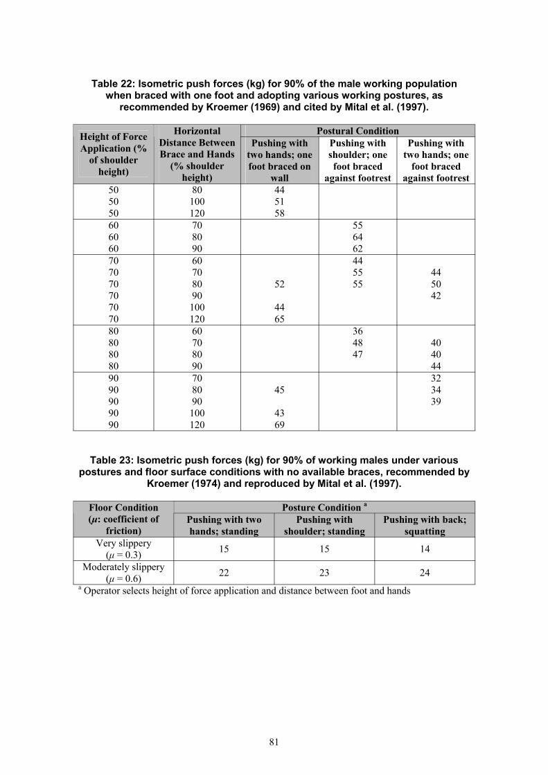
Table 22: Isometric push forces (kg) for 90% of the male working population when braced with one foot and adopting various working postures, as
recommended by Kroemer (1969) and cited by Mital et al. (1997).
Height of Force Application (%
of shoulder height)
Distance Between Brace and Hands
(% shoulder height)
Horizontal Pushing with
two hands; one foot braced on
wall
Pushing with shoulder; one foot braced
against footrest
Postural Condition Pushing with
two hands; one foot braced
against footrest 50 50 50
80 100 120
44 51 58
60 60 60
70 80 90
55 64 62
70 70 70 70 70 70
60 70 80 90 100 120
52
44 65
44 55 55
44 50 42
80 80 80 80
60 70 80 90
36 48 47
40 40 44
90 90 90 90 90
70 80 90 100 120
45
43 69
32 34 39
Table 23: Isometric push forces (kg) for 90% of working males under various postures and floor surface conditions with no available braces, recommended by
Kroemer (1974) and reproduced by Mital et al. (1997).
(µ: coefficient of friction)
Floor Condition Pushing with two hands; standing
Pushing with shoulder; standing
Posture Condition a
Pushing with back; squatting
Very slippery (µ = 0.3) 15 15 14
Moderately slippery (µ = 0.6) 22 23 24
a Operator selects height of force application and distance between foot and hands
81

82

7.4 APPENDIX D – SUMMARY OF SPECIFIC TROLLEY DESIGN GUIDELINES
Table 24: Summary of Trolley Design Guidelines (Lawson et al., 1994)
Height · Maximum trolley height of 140 cm
Trolley Dimensions Recommendations
· Arrange trolley stacking so no goods, can be stored above 1.4 metres
· If the trolley is too high, allow visibility through the frame, mesh or bars at eye level
· High trolleys should be moved with one user at each end for safety
Length · Trolley length should be 1.5 – 2 times its
width · Longer trolleys should be steered with two
operators Width · Width trolleys are preferred but width should
be at least: - 8 cm less than narrowest doorway for hand pushing/pulling trolley
- 50 cm less than narrowest doorway for towing single trolley
- 70 cm less than narrowest doorway for multiple trolleys
Shelf Height & Design · Maximum shelf height of 140 cm · Optimal shelf height of 80 – 110 cm (knuckle
to elbow height) for heavy and frequently used items
· Only store light and infrequently used items on shelves lower than 60 cm and higher than 110 cm
· Consider self adjusting units with bin trolleys or platform trolleys to raise loads to optimal working height
· If heavy loads must be placed on the bottom shelf, recess the shelves at knee height to allow the operator to face to load when lifting
· Shelf depth should not exceed 80 cm at 80 – 120 cm heights; 45 cm at heights < 80 cm; and 30 cm at 120 – 140 cm heights
· Avoid small clearances between shelves · Consider guard rails during use · Shelves should be smooth and either
horizontal or sloped slightly inwards
joint strain · Taller operators will have to bend slightly to use shelves with heights of 60 – 80 cm
· Shelves under 60 cm cause too much operator bending
· Wide shelves may lead to awkward reaching postures when loading and unloading items
· Loads should be placed on the shelf edge and slid into place.
· Sloped or guarded shelves resist the load sliding off during use
· High trolleys obstruct visibility. 1.4 metres based on the 5th percentile female shoulder
Reasons
height (Pheasant, 1986). Operators may constrain posture to peer around trolley edges
· High narrow trolleys lack sideways stability and can topple on sloped floors or if moving quickly around corners
· High trolleys create higher stacking heights and have a greater volume (total load)
· Long trolleys may be difficult to steer or fit into small spaces (e.g. lifts). This may increase manoeuvring forces.
· Long trolleys may be difficult to tow
· Tight space between doorways and trolleys may lead to pinched fingers and trapped upper limbs
· If trolley access is restricted, more lifting and carrying will occur
· Wider trolleys are more stable, as long as castors are spaced far apart
· Lifting above elbow and shoulder height places operator under greater muscle and
83

· Ensure it is easy to detach and refit the sides
Recommendations External Features Sides / Gates · Consider mesh, bars or plates on sides · Consider detachable gates rather than fixed
sides · If carrying liquids, trolley floors should
contain any spills until they can be mopped out later
or gates and there are no sharp edges Handle Design · Fit at least one handle to a trolley · Fit handles in from the sides of trolleys · Trolleys with 4 swivel castors will require
handles at both ends · Handles should allow grip between 91 cm –
100 cm · Handles may be positioned horizontally or
vertically. Vertical handles should be spaced about 45 cm apart from each other
· Handle diameters should be between 2.5 and 4 cm
· Allow clearance of 12 cm to clear palm breadth and 5 cm to clear the knuckles. Allow additional clearance when wearing gloves
· Allow 20 cm clearance out from the back edge of trolleys used at low speeds, and 40 cm for trolleys used at higher speeds
· Handles should be cylindrical, smooth and
confined spaces · Vertical handles allow users to find their
optimal height; horizontal handles allow selection of optimal hand separation
· Small handle diameters cramp the grip while larger diameters are uncomfortable
· Sufficient hand clearance is required to grip the handle quickly and easily
· Handle clearance from the trolley required so ankles do not hit shelves when taking a good stride
· Cylindrical handles best for safe power grips · Un-insulated handles may become hot or
cold with environmental changes
Reasons
· Mesh or bars allow improved visibility through the trolley and lighter construction
· Plates may protect against dust, spill, etc. · Detachable gates allow access to goods for
improved manual handling
· Using trolleys without handles, or handles at the edges, risks crushing fingers
· Handles at both ends improve mobility in
· Trolley weight should be about 25% of the
have no sharp edges. Consider a replaceable insulating material on the handles
Buffers · Fit appropriate buffers, made from impact
absorbing material (e.g. rubbers, polyurethane)
Towing Fixtures · Tow bars, hitches, brackets and other
couplings must be designed, constructed and fitted appropriately. Couplings must be robust and secure.
· For towing, heavy duty castors or wheels must be used (20 cm minimum diameter)
· Trial all towing trolleys in their environment Material & Structure
load for which it is designed · Consider hygiene / cleaning requirements · Consider hot, cold, wet or chemically
exposed environments
· Frame material and structure affects trolley
· Buffers reduce damage to trolleys, walls, doors and other equipment and thus reduce the amount of splinters, metal slivers and roughness that can damage people
· Towing causes high impact loads and trolleys and castors must be especially strong
· Trolleys that break loose at speed are an immediate and serious danger
· Castors for manual pushing/pulling are usually unsuitable for towing
weight, rigidity, durability, visibility through the frame, noise, vibration, potential for cuts and scratches, and selection of castors
84

· Trolleys with 2 fixed (front) and 2 swivel
Recommendations Wheels and Castors Wheel & Castor Alignment · Castors should be positioned at all corners of
the trolley · Trolleys with 4 swivel castors are best for
congested / confined areas. Consider a directional lock on one of the castors
(rear) castors are best for longer distances, and short distances. They are difficult to
Reasons
· Trolley corners without castor support may be unstable with heavy loads or when on slopes
· Trolleys with 4 swivel castors are highly manoeuvrable and suitable for level floors
steer on uneven of sloped floors
· Minimum castor diameter of 20 cm for all
sloped paths and outdoor use · Trolleys with 4 swivel castors at corners and
2 fixed castors at centre are best for heavy loads, long trolleys and long travel distances
Wheel and Castor Diameter · Larger diameter wheels reduce the forces for
· Trolleys with fixed castors require more space for turning and cannot be pushed sideways into small spaces, but are easier to steer over long distances
trolleys
trolleys with loads over 200 kg or used outdoors
· Minimum diameter of 12.5 cm for all other
· Smaller diameters (7.5 – 10 cm) may be acceptable for light loads and short distances on smooth floors, without obstructions.
Tyre Material · Non-marking rubber or polyurethane tyres
are recommended · Hard plastic materials (e.g. nylons) should
only be used if all pushing and pulling is restricted to carpet and there are no obstructions
· Pneumatic tyres are only recommended for the roughest surfaces (e.g. roads and gravel)
Bearings · Use high quality bearings · Establish and maintain a regular greasing and
maintenance programme · Use total brakes whenever the trolley is to be
immobilised · Use wheel lock to lock rolling movement
only Thread guards · Fit thread guards
·
Springs · Use spring castors for transportation of heavy
fragile goods or in outdoor environments ·
· Larger wheels are more resilient to damage
all trolley manoeuvring. They roll over ridges and irregular floor surfaces with greater ease and less vibration
· Softer tyres absorb shocks well but require more force to move. If tyres are too soft though (i.e. flat), forces increase drastically
· Nylons swivel easily on carpets but pick up gravel and leave indents on some flooring
· Harder tyres are generally noisier and cannot be used across a variety of surfaces
· Pneumatics have problems maintaining pressure in smaller sized wheels
· High quality bearings reduce forces to move trolleys and help maximise the load within the force guidelines
· With total braking, the wheel and head swivel is locked, giving maximum stability
· Wheel lock only is not suitable if any work is to be performed on the trolley as it moves forward or backwards Thread guards prevent lint or thread from wrapping around the wheel axles and slowing rotation. They also protect the bearings from dirt and moisture
Spring castors reduce rattle and bounce over bumps
85

86

7.5 APPENDIX E – MODELS USED TO PREDICT PUSHING AND PULLING CAPABILITIES
Table 25: Psychophysical model of push / pull capabilities (Mital, 1983)
Pushing capacity
Dependent Variable
(kg)
Pulling capacity
(kg)
Type of task
Male
Gender
Female
Male
Female 0.331x LN(F)
PC = 17.29 - 0.166 x HD - 11.45 x F + 0.0013 x (HD^2) + 5.60 x (F^2) + 0.001 x (1/F) + 0.047 x HD x F
Model
PC = 10.31 - 0.133 x HD - 16.15x F - 0.154 x LN(F) + 6.17 x EXP(F) + 0.056 x HD x F PLC = 18.48 - 0.685 x F - 0.0003 x (VD^2) + 0.003 x VD x F - 0.5 x LN(F) PLC = 15.03 - 0.394 x F - 0.0003 x (VD^2) -
0.968
R2
0.96
0.978
0.945
Key PC: Pushing capacity (kg)PLC: Pulling capacity (kg)HD: Horizontal distance of push (m) VD: Vertical distance of pull (height of force application - cm) F: Frequency of push/pull (times/min)
Table 26: Physiological model of push / pull capabilities (Garg et al., 1978)
Dependent Variable Type of task Model
Pushing/pulling at bench NMR = 0.00112 x HM x BW + 0.0115 x F + height (0.8 m) 0.00505 x F x G Net metabolic rate
(Kcal/push) Pushing/pulling at 1.5 m NMR = HM x (0.086 + 0.036 x F) height
Key NMR:Net metabolic rate for the activity performed BW: Body weight (kg)HM: Horizontal movement of work piece (m) F: Average pushing/pulling force applied by hands (kg)G: Gender (male=1, female=0)Both models are valid for a duration of less than one hour.
87

Table 27: Combined model of push / pull capabilities (Shoaf et al., 1997)
Model PC = FB
PLC = FB
Dependent Variable Type of task Pushing capacity (kg) Generic x V x T x F x AG x BW x TD Pulling capacity (kg) Generic x V x T x F x AG x BW x TD
Key PC: Pushing capacity (kg) PLC: Pulling capacity (kg) FB: Maximum force acceptable to a specified percentage of worker population (kg) and is
also a function of type of force (initial or sustained) V: Multiplier for vertical distance from floor to hands (cm) T: Multiplier for travelled distance F: Multiplier for frequency of push/pull AG: Age group multiplier BW: Body weight multiplier TD: Task duration multiplier
Table 28: Base forces for pushing and pulling (Shoaf et al., 1997)
Initial Push Sustained Push Initial Pull Sustained Pull Population Force (kg) Force (kg) Force (kg) Force (kg)
% Male Female Male Female Male Female Male Female 66.5 39.6 44.2 31.5 62.5 38 44.5 30.75 62.2 37.3 41.5 29.4 59.4 36.1 41.7 28.810 59.5 35.9 39.7 28 57.1 34.8 39.9 27.515 57.8 34.5 38.2 26.9 55.8 33.9 38.4 26.520 55.7 33.9 37 25.9 54 32.7 37.1 25.625 53.9 33 35.9 25 52.3 32 36 24.830 52.2 32.2 34.9 24.2 51.6 31.3 34.9 2435 50.8 31.4 33.9 23.5 50.3 30.5 33.9 23.340 49.3 30.6 32.9 22.7 49.2 29.8 33 22.745 48 30 32 22 48 29.1 32 2250
46.5 29.4 31.1 21.3 46.9 28.4 31 21.355 45.8 28.6 30.1 20.5 46 26.9 30 20.760 43.9 27.9 29.1 19.8 44.8 26 29.1 2065 42.2 27 28.1 19 43.5 26.1 28 19.270 40.4 26.3 27 18.1 42.2 25.5 26.9 18.475 38.8 25.7 25.8 17.1 40.7 24.3 25.6 17.580 36.3 24.2 24.3 16 38.9 23.7 24.1 16.585 34 23 22.5 14.6 36.8 22 22.3 15.290
95 29.9 20.8 19.8 12.5 33.9 20.1 19.5 13.3
88

Table 29: Body weight multiplier (Shoaf et al., 1997)
Weight (kg) Male Female 40 0.7 1 45 0.7 1 50 0.7 1 55 0.7 1 60 0.7 1 65 0.8 1.2 70 1 1.4 75 1.2 1.68 80 1.3 1.85 85 1.41 1.98 90 1.45 2.05 95 1.45 2.05
100 1.45 2.05
Table 30: Task duration multiplier (Shoaf et al., 1997)
Duration (hr) Multiplier 10 11
0.772 0.673 0.64
0.585 0.546 0.57
0.458
89

Table 31: Vertical height multiplier for pushing and pulling (Shoaf et al., 1997)
Height (cm)
Initial Push Male Female
Sustained Push Male Female
Initial Pull Male Female
Sustained Pull Male Female
60 - - - - 1 1 1 1 65 - - - 0.983 0.993 0.993 0.995 70 - - - 0.966 0.987 0.984 0.99 75 - - - 0.947 0.981 0.974 0.985 80 - - - 0.928 0.975 0.962 0.979 85 - - - 0.908 0.969 0.949 0.973 90 0.988 0.971 0.989 0.983 0.887 0.964 0.935 0.967 95 0.996 0.984 0.995 0.992 0.865 0.958 0.919 0.96
100 1 0.993 0.999 0.998 0.842 0.953 0.901 0.953 105 0.999 0.998 1 1 0.818 0.949 0.882 0.945 110 0.993 1 0.999 0.999 0.794 0.944 0.862 0.937 115 0.982 0.998 0.996 0.994 0.768 0.94 0.84 0.929 120 0.966 0.992 0.99 0.985 0.742 0.936 0.817 0.92 125 0.945 0.982 0.983 0.973 0.715 0.932 0.792 0.911 130 0.92 0.969 0.972 0.958 0.687 0.929 0.765 0.902 135 0.889 0.952 0.96 0.939 0.658 0.926 0.738 0.892 140 0.854 0.931 0.945 0.917 0.628 0.922 0.708 0.882
Table 32: Travel distance multiplier for pushing and pulling (Shoaf et al., 1997)
Distance (m)
Initial Push Male Female
Sustained Push Male Female
Initial Pull Male Female
Sustained Pull Male Female
1 - - - - 1 1 1 1 5 - - - 0.93 0.95 0.831 0.972
10 - - - - 0.878 0.856 0.743 0.877 15 - - - 0.845 0.752 0.697 0.75 20 0.732 0.741 0.597 0.637 0.785 0.739 0.631 0.696 25 0.6667 0.719 0.552 0.583 0.717 0.726 0.562 0.655 30 0.614 0.71 0.511 0.537 0.657 0.713 0.514 0.625 35 0.577 0.708 0.474 0.52 0.614 0.7 0.49 0.604 40 0.548 0.713 0.44 0.534 0.577 0.687 0.466 0.587 45 0.523 0.711 0.409 0.536 0.547 0.674 0.442 0.565 50 0.499 0.695 0.383 0.504 0.524 0.657 0.418 0.532 55 0.476 0.671 0.36 0.455 0.505 0.631 0.394 0.492 60 0.455 0.638 0.341 0.338 0.491 0.6 0.37 0.446 65 0.438 0.597 0.326 0.305 0.485 0.568 0.347 0.393
90

Table 33: Frequency multiplier for pushing and pulling (Shoaf et al., 1997)
Frequency (times/min)
Initial Push Male Female
Sustained Push Male Female
Initial Pull Male Female
Sustained Pull Male Female
0.002 1 1 1 1 1 1 1 1 0.016 0.901 0.956 0.894 0.877 0.898 0.958 0.909 0.864 0.03 0.854 0.933 0.844 0.818 0.851 0.938 0.865 0.8 0.1 0.843 0.919 0.83 0.795 0.842 0.924 0.852 0.783 0.2 0.833 0.9 0.813 0.773 0.83 0.906 0.838 0.76 0.5 0.813 0.8 0.719 0.727 0.787 0.813 0.73 0.68 1 0.792 0.767 0.688 0.682 0.766 0.781 0.703 0.64 4 0.542 0.667 0.438 0.545 0.7 0.783 0.598 0.62 6 0.557 0.6 0.203 0.455 0.663 0.696 0.539 0.568
91

92

8 REFERENCES
Al-Eisawi, K.W., Ker, C.J., Congleton, J.J., Amendola, A.A., Jenkins, O.C., and Gaines, W.(1999) Factors affecting minimum push and pull forces of manual carts. Applied Ergonomics, 30, 235– 245.
Baril-Gingras and Lortie (1995) The handling of objects other than boxes: univariate analysis of handling techniques in a largetransport company. Ergonomics, 38, 905 – 925.
Boocock, M.G. (2003) Detailed analysis of push-pull accidents recorded on HSE’s RIDDOR accident database. HSL Internal Report ERG/03/08.
BS EN 1005-3 (2002) Safety of machinery – Human physical performance – Part 3: Recommended force limits for machinery operation. BSI 02-2002, ISBN 0 580 39178 7.
BS EN ISO 14122-1 (2001) Safety of machinery – Permanent means of access to machinery – Part 1: Choice of a fixed means of access between two levels. BSI 08-2001, ISBN 0 580 37016 X.
BS EN 1789 (1999) Medical vehicles and their equipment – Road ambulance. BSI 01-2000, ISBN 0 580 35243 9.
BS 6109-2 (1989) Tail lifts, mobile lifts and ramps associated with vehicles – Part 2: Code of practice for passenger lifts and ramps. BSI 02-1999, ISBN 0 580 17116 7.
BS PD 6523 (1989) Information on access to and movement within and around buildings and on certain facilities for disabled people. BSI Published Document.
Caldwell, L.S. (1964) Body position and the strength and endurance of manual pull. Human Factors, 6, 479 – 484.
Chaffin, D.B., Andersson, G.B.J., and Martin, B.J. (1999) Occupational Biomechanics. 3rd Edition. John Wiley & Sons, Inc., New York.
Clemmer, D.I., Mohr, D.L., and Mercer, D.J. (1991) Low back injuries in heavy industry I: Worker and workplace factors. Spine, 16, 824 – 830.
Davis, P.R. and Stubbs, D.A. (1980) Force Limits in Manual Work. IPC Science and Technology Press, Guildford, UK. ISBN0861030346
Garg, A. and Moore, J.S. (1992) Epidemiology of low back pain in industry. Occupational Medicine: State of the Art Reviews, 7,593 – 608.
93

Garg, A., Chaffin, D.B., and Herrin, G.D. (1978) Prediction of metabolic rates for manual material handling jobs. American Industrial HygieneJournal, 39, 661 – 674.
Hoozemans, M.J.M., van der Beek, A.J., Frings-Dresen, M.H.W., van Dijk, F.J.H. and van derWoude, L.H.V. (1998) Pushing and pulling in relation to musculoskeletal disorders: a review of risk factors. Ergonomics, 41, 757 – 781.
Health and Safety Commission (HSC) (2000) Securing Health Together: A long term occupational health strategy for England, Scotland and Wales. HSE Books, Sudbury, Suffolk, MISC 225.
Health and Safety Executive (HSE) (1998) Manual Handling. Manual Handling Operations Regulations 1992: Guidance on Regulations. HSE Books, Sudbury, Suffolk. L23, Second edition. ISBN 0 7176 2415 3.
Health and Safety Executive (HSE) (1992) Personal protective equipment at work. Personal Protective Equipment at Work Regulations1992: Guidance on Regulations. HSE Books, Suffolk, Sudbury. L25. ISBN 0 7176 0415 2.
ISO/WD 11228-2 (2002) Ergonomics – Manual handling and force limits – Part 2: Pushing and pulling. ISO WorkingDraft, 2002.
Konz, S. (1999) Posture. In: Kumar, S. (ed), Biomechanics in Ergonomics. Taylor & Francis, London, ISBN 07484 0704 9.
Kroemer, E.K.H. (1974) Horizontal push and pull forces exertable when standing in working positions on varioussurfaces. Applied Ergonomics, 5, 94 – 102.
Kroemer, E.K.H. (1970) Human strength: terminology, measurement and interpretation of data. Human Factors, 12(3),297 – 313.
Kroemer, E.K.H. (1969) Push forces exerted in 65 common working positions. Report No. AMRL-TR-68-143,Aerospace Medical Research Laboratory, Wright-Patterson Air Force Base, Ohio, USA.
Lawson, J., Potiki, J and Watson, H. (1994) Ergonomics guidelines for manually-handled trolleys in the health industry, Central SydneyHealth Service, Work Safe Australia.
Lee, K.S., Chaffin, D.B. and Parks, C. (1992) A study of slip potential during cart pushing and pulling. IEE Transactions, 24, 139 – 146.
Lee, K.S., Chaffin, D.B., Herrin. G.D. and Waikar, A.M. (1991) Effect of handle height on lower-back loading in cart pushing and pulling. Applied Ergonomics, 22, 117 – 123.
94

Manning, D.P. (1983) Deaths and incidents caused by slipping, tripping and falling. Ergonomics, 26, 3 – 9.
Martin, J.B. and Chaffin, D.B. (1972) Biomechanical computerised simulation of human strength in sagittal plane activities, AIIETransactions, 4, 19 – 28.
Mital, A. and Kumar, S. (1998a) Human muscle strength definitions, measurement and usage: Part I – Guidelines for thepractitioner. International Journal of Industrial Ergonomics, 22, 101 – 121.
Mital, A. and Kumar, S. (1998b) Human muscle strength definitions, measurement and usage: Part II – The scientific basis(knowledge base) for the guide. International Journal of Industrial Ergonomics, 22, 123 – 144.
Mital, A., Nicholson, A.S. and Ayoub, M.M. (1997) A guide to manual materials handling. 2nd Edition. Taylor & Francis, London.
Mital, A. (1983) Generalised model tructure for evaluating/designing manual handling materials handling jobs.International Journal of Production Research, 21, 401 – 412.
McPhillips, L. (1997) Manual handling operations involving pushing and pulling. Health and Safety Executive,Health Directorate.
National Institute of Occupational Safety and Health (NIOSH) (1997) Musculoskeletal Disorders and Workplace Factors: A Critical Review of Epidemiologic Evidence for Work-Related Musculoskeletal Disorders of the Neck, Upper Extremity, and Low Back. DHHS Publication No. 97-141, NIOSH Publication Dissemination, Cincinnati, Ohio, USA.
National Occupational Health and Safety Commission (NOHSC) (1999)Moving Trolleys: Reducing Manual Handling Injuries When Moving Trolleys, Work SafeAustralia.
Roebuck, B. and Norton, G. (2002) Safety of roll containers. HSE Research Report 009/2002. HSE Books. ISBN 0 7176 2535 4.
Shoaf, C., Genaidy, A., Karwowski, W., Waters. T. and Christensen, D. (1997) Comprehensive manual handling tasks: revised tables of maximum acceptable weights andforces. Ergonomics, 34, 1197 – 1213.
Snook, S.H. and Ciriello, V.M. (1991) The design of manual handling tasks: revised tables of maximum acceptable weights and forces.Ergonomics, 34, 1197 – 1214.
Snook, S.H. (1978) The design of manual handling tasks. Ergonomics, 21, 963 – 985.
95

Printed and published by the Health and Safety ExecutiveC30 1/98
Printed and published by the Health and Safety Executive C1.10 05/04

ISBN 0-7176-2845-0
RR 228
78071 7 62845 2£25.00 9

Revie
w o
f the risk
s asso
ciate
d w
ith p
ush
ing a
nd
pullin
g h
eavy lo
ad
s H
SE
BO
OK
S