Embed Size (px)
Citation preview

Research On Energy Saving and PerformanceEnhancement of High-End Hydraulic Press WithControllable AccumulatorLin Hua
Wuhan University of Technology - Mafangshan Campus: Wuhan University of TechnologyZhicheng Xu ( [email protected] )
Wuhan University of Technology https://orcid.org/0000-0002-6321-591XYanxiong Liu
Wuhan University of technologyXinhao Zhao
Wuhan University of technology
Original Article
Keywords: High-end hydraulic press, Energy saving, Hydraulic system, High working performance
Posted Date: January 29th, 2021
DOI: https://doi.org/10.21203/rs.3.rs-155423/v1
License: This work is licensed under a Creative Commons Attribution 4.0 International License. Read Full License

1
Research on energy saving and performance 1
enhancement of high-end hydraulic press with 2
controllable accumulator 3
Lin Hua1, 2#, Zhicheng Xu1 2, 4#, Yanxiong Liu1, 2, Xinhao Zhao1, 3 4
Abstract: Hydraulic fineblanking press is a kind of high-end hydraulic metal forming devices and 5
widely applied in automotive and appliance industry. However, it suffers from the defeat of high energy 6
consumption low energy efficiency. To solve the problem, this study proposed a power-matching 7
strategy by using a novel controllable accumulator which can control the precharge pressure, output 8
flow with high precision. Firstly, the energy characteristics and working performance requirements of 9
the large-sized fineblanking press in a working cycle were investigated. Then, the energy consumption 10
mathematic model coupling with the controllable accumulator was built for designing the key 11
parameters of the accumulators. Based on the load characteristic and the energy model, a controlling 12
strategy of the controllable accumulator was proposed to reduce the imbalance degree of the supplied 13
and demanded power and improve working performance by designing working route of the 14
controllable accumulator. Finally, a detailed hydraulic schematic was designed and applied on the 1000 15
ton hydraulic fineblanking press, which was validated with simulation model. The results show that 16
compared to the traditional system, the energy efficiency of the novel system is improved by 20.35% 17
with lowering the input energy by 169.4 kJ. Besides, the vibration magnitude of the slide block is 18
decreased a lot and the working production efficiency is improved by 10% compared to the traditional 19
system. 20
# The authors Lin Hua and Zhicheng Xu contributed equally to this work. Corresponding author. [email protected] (Zhicheng Xu), [email protected] (Yanxiong Liu )

2
Keywords: High-end hydraulic press; Energy saving; Hydraulic system; High working performance 21
Nomenclature Abbreviations FC Fast-closing stage pn Motor nominal power (W) AD Anomaly detection stage l Pipe length (mm) FB Fineblanking stage ps Overflow pressure UP Pressure unloading stage pu SAM output power (W) FO Fast-opening stage Tout Pump output torque (Nm) PID Proportion integration differentiation Tfic Pump internal friction torque (Nm) Symbols vt Oil velocity in pipe (m/s) Aj Contact area between the piston and
the cylinder block (mm2) x0 Spool displacement (mm)
c Flow coefficient of cartridges valves (Null)
pu SAM output power (W)
Cic Internal leakage coefficient of the cylinder (W/bar2)
L1 FC stroke
Cs Pump leakage flow rate (Null) L2 AD stroke dc Valves spool diameter (mm) L3 Whole stroke Bc Friction coefficient (N/m2) x1 Target signal k1 , k2 Constant value parameters of motor
(Null) Greek
qd Overflow flow (m3/s) ηv Pump volumetric efficiency (Null) l Pipe length (mm) ηm Pump mechanical efficiency (Null) np Pump rotational speed (r/min) μ Dynamic viscosity of the oil (Ns/m2) Pa Valves input pressure (Pa) ρ Oil density (kg/m3) Pb Valves output pressure (Pa) α Valves spool cone angle(°) pe Motor power loss (W) λ Resistance coefficient along the pipe
(Null) pf Pipe local loss (W) Δq Pump leakage flow (m3/s) pj Power loss along in parallel pipe (W)
22
1. Introduction 23
With the increasing of the energy shortage and the worsening of the natural environment, the 24
energy conservation and the emission reduction concept has been attracted more and more attention all 25
around the world, which is also an effective way to relieve these problems. On the other hands, with the 26
fast development of the industrial manufacturing, the CO2 emission was increased rapidly, which has 27

3
caused the sea level rise and the extreme climate in recent years. To deal with these serious problems, 28
many international organizations and countries have worked together and assigned some policy of 29
emissions reduction, such as Paris assignment. It is reported that about 31% of total electricity were 30
consumed by the industrial activity in 2012 in the U.S [3], of which the manufacturing industry 31
accounted for 90% . Hence, the manufacturing industry is a huge CO2 emissions source caused by the 32
usage of machine tool and press . For these equipment, the most common used method of power 33
transmission is the hydraulic system, especially for these machine with large power, because of high 34
power ratio, long-life, high reliability, convenient stepless speed regulating, auto-control and flexible 35
transmission direction. Actually, most of high power machines take hydraulic transmission as the main 36
driven system with no alternative in present technology. However, the low energy efficiency of 37
hydraulic driven system is also a serious problem, especially in the state of global energy shortage and 38
increased greenhouse effect, which is getting more and more prominent. 39
In the metal forming filed, the hydraulic fineblanking press is the top class because of highest 40
manufacturing precision and production efficiency. The working capacity of the hydraulic fineblanking 41
press can achieve 1000 ton with 30~80 pieces per minute, which requires the demanding working 42
performance of the hydraulic system and bigger installed power compared to the ordinary press [6]. 43
However, the hydraulic fineblanking press suffers from the same drawbacks with the ordinary press - 44
low energy efficiency only 10% and causes great energy wasted. From the aspect of functions, the 45
forming equipment can be divided into several parts: controller, main hydraulic transmission system, 46
mold and cooling system. Most of energy about 90% of the total input energy is consumed by the 47
hydraulic transmission system. Hence, there is great potential in improving the energy utilization 48
efficiency of hydraulic system [7]. 49

4
A high-accuracy energy consumption model is the basis of analyzing energy distribution, which 50
is helpful to better explore the root of low energy efficiency of hydraulic system. From the point of the 51
components level, the energy consumption calculation model of the motor-pump units was built by 52
considering the input and output power, which was able to calculate the static and dynamic properties 53
of the hydraulic system . Furthermore, a more detailed energy consumption model was provided for 54
calculating the power loss of each hydraulic element involving the motor, pump, pipe, valve and so on, 55
which showed a high accuracy . From the aspect of the energy forms, the energy conversion forms of 56
the whole hydraulic system was divided into six parts which comprised electric-mechanical energy, 57
mechanical-hydraulic energy, hydraulic-hydraulic energy, hydraulic-mechanical energy, 58
mechanical-deformation energy, thermal-thermal energy with corresponding impact factors [10]. 59
However, this model is not easy to use impractically because of too many unknown parameters to be 60
tested in advance. Summarily, the authors Xu and Zhao both indicated that the great energy loss and 61
low energy efficiency mainly resulted from the imbalance of the supplied and the provided energy. 62
To date, many researches have been carried out for improving the energy efficiency, 63
concentrating on three aspects: system structure optimization, high efficiency components and energy 64
management strategies. Intrinsically, all these methods are trying to reduce the energy gap between the 65
supplied and the provided energy. 66
Initially, the structure of hydraulic system is very simple with simple function. With the 67
increasing requirements of the machine, more and more novel functions were developed and added in 68
the hydraulic system such as pressure reduction and flow controlling functions, most of which aimed at 69
improving the working performance rather than energy efficiency in early years. To improve the energy 70
efficiency, a novel closed-loop hydrostatic transmission (HST) system with two hydraulic accumulators 71

5
was proposed to recover the kinetic energy without any reversion of the fluid flow based on the 72
adaptive fuzzy sliding mode control strategies . This new system saved 10% to 20% more energy than 73
that of the traditional HST system . An energy-saving fast forging system schematic of two-stage 74
pressure source was presented to match the load of different actuators, tested on the 0.6 MN hydraulic 75
forging press platform . In addition, the variable-frequency pump with accumulator, aiming at 76
controlling the output pressure of the pump, was integrated to achieve zero overflow loss through 77
applying fuzzy self-turning closed-loop control strategy, which gained the total energy consumption 78
reduction by 65.3% . The single drive system was separated into several drive subsystems shared by 79
several presses to shorten the waiting time by optimizing the processing schedule [15]. Results showed 80
that the energy efficiency of a single hydraulic press in the group is increased by approximately 20% 81
and the average energy consumption can be reduced by 43% compared with the traditional device. 82
Furthermore, a novel energy-efficient system that created a sharing circuit is proposed to connect two 83
actuators by pipes and valves, which could synchronize the falling procedure of one cylinder with the 84
returning procedure of the other. Compared to the undergoes services, this new structure can reduced 85
the energy consumption by 20.61% . A new hydraulic regulation method on district heating system 86
with distributed variable-speed pumps was presented to achieve on-site hydraulic balance for the 87
district heating systems and the energy saving ratio of the district system was 36.1–90.3% less than that 88
of the conventional central circulating pump configuration . To improve the energy efficiency, a 89
combined valve-pump combined with multiple accumulators was presented to match the load profile of 90
fineblanking process . The authors Joshua D and Andrea used the variable displacement with the 91
pressure regulation valves to achieve loading sensing function on excavator, which can match the load 92
well and reduce the overflow loss in idle stage. To reduce the product cost of power unit, a 93

6
speed-controlled induction motor in combination with a constant-displacement pump was applied in a 94
load-sensing control strategy and gained a good energy-saving effect [21]. A displacement variable pump 95
driven by a speed variable electric motor as power source was proposed integrated with a matching 96
method based on the segmented speed and continuous displacement control of the pump, and the 97
energy saving ratio under partial load condition can be up to 33% . There are also other different 98
functions valves integrated on the variable pump to achieve negative-flow control circuit, positive-flow 99
control circuit, and constant power control circuit and so on. These variable pumps with certain 100
functions can save energy to some certain. 101
Another effective way to reduce energy consumption and improve energy efficiency is to 102
recovery the waste energy . This way can make up the gap between the supplied and the demanded 103
energy although the supplied energy cannot match the load profile well. In most case, the energy 104
storage device absorbs the extra energy such as the potential energy of heavy motion part, overflow 105
energy of machining idle time from the power unit, the mechanical energy of rotation part while 106
slowing down . Considering the types of the energy storage device in hydraulic system, the most 107
common used is the hydraulic accumulator because it can be easily integrated into the hydraulic system. 108
The most important thing is no secondary conversion of different energy types for ensuring few energy 109
loss in the energy storage and releasing process while using hydraulic accumulator, which is superior to 110
the chemical battery in which the hydraulic energy should be converted into the kinetic energy of the 111
generator rotor firstly and then converted into electricity by the electro-magnetic induction principle 112
with low conversion efficiency. 113
Equipped with the hydraulic accumulator, many energy regeneration circuit and systems are 114
developed. In construction machine , an energy alternate recovery and utilization system based multiple 115

7
hydraulic cylinders and hydraulic accumulator was proposed to recovery the potential energy of the 116
bucket, the stick and the boom, which gained comprehensive energy-saving rate is 41.6% compared 117
with the original system . a gravitational potential energy recovery circuit with an energy conversion 118
cylinder and a hydraulic accumulator was proposed [28]and these recovery energy can be reused directly 119
without increasing the cost and install power of the machine largely. A valve–motor–generator and a 120
hydraulic accumulator was used for a hybrid hydraulic excavator to recovery the potential energy and 121
got the total energy efficiency of 58% [29]. A two-level idle speed control system comprised three stages 122
of idle speed control with a hydraulic accumulator were invented . By optimizing the key parameters, 123
the energy saving efficiency was approximately 36.06%. In addition, the hydraulic accumulator is also 124
applied on the automobile for recovering the braking energy. A new braking pressure coordinated 125
control system was proposed to regenerate the braking energy with three hydraulic accumulators and 126
the braking energy recovery rate reached 47-66% [31]. A hybrid power system, involving the hydraulic 127
power unit was proposed and the accumulator was applied to regulate the power relationship between 128
this two power supply units, to save fuel consumption by up to 11%. A regenerative hydraulic shock 129
absorber system was proposed [33], which converts the oscillatory motion of a vehicle suspension into 130
unidirectional rotary motion of a generator and improved the energy efficiency by 40%. In addition, the 131
hydraulic accumulator is also widely applied on the wave energy recovery field , which functions as 132
storing energy and pressure stability to improve the energy conversion efficiency. 133
Although the hydraulic accumulator is widely used in various fields like construction machinery, 134
wave energy capturing and automobile, there still exits some drawbacks such as the limited capacity 135
and uncontrollability resulted from the coupling of the output pressure and flow. To increase the energy 136
storage capacity, the utilization efficiency of accumulator with and without elastomeric foam was 137

8
investigated and the result showed the accumulator had a constant efficiency of about 95% with fully 138
filled with foam . A double-bladder accumulator with filled metallic filler was invented to maintain the 139
isothermy of the gas, which can improve the energy capacity and the dynamic performance . However, 140
the manufacturing process of this kind of accumulator is complex with high cost. A novel hydraulic 141
accumulator that used a piston with an area that varies with stroke to maintain a constant hydraulic 142
system pressure was presented . The results showed that about 16% improvement of energy density 143
was obtained over a conventional accumulator a and the maximum energy density of this novel 144
accumulator was improved to 2.7:1 from 1.8:1. The mechanical flywheel and the hydraulic 145
accumulator was combined to increase the energy storage density, which was applied in the lift system. 146
The analysis results indicated that this novel accumulator maybe solve the problem of the coupling 147
between the pressure and the flow . Although abovementioned methods are potential to improve the 148
energy capacity of the accumulator, few researches are focused on the working performance and the 149
controllability of hydraulic accumulator. 150
Although many advanced energy-saving systems have been developed and much works have 151
been carried out on the hydraulic accumulator for improving the energy capacity, there still lacks of a 152
comprehensive research about the application of hydraulic accumulator on this advanced hydraulic 153
system to achieve high work performance and excellent energy saving effect at the same time. To 154
further improve the overall performance of the fineblanking press, this study proposed a double stage 155
pressure hydraulic system with a novel controllable accumulator with the ability for solving the 156
coupling problem between the output pressure and flow. This novel system can make full use of the 157
hydraulic controllable accumulator with four working modes to eliminate the imbalance of the 158
demanded and the supplied energy with improving the working performance of the fineblanking 159

9
processing. This study also provided an alternative high-end hydraulic system with high energy 160
efficiency for the metal forming filed. To validate the feasibility of this novel system, a simulation 161
reearch of 1000 ton hydraulic fineblanking press was built to analyze the working performance and 162
energy distribution characteristic. 163
This paper is organized as follows: Section 2 presents the working principle of hydraulic system 164
as well as the novel accumulator; Section 3 establishes energy consumption models of the whole 165
system; Section 4 calculates the key parameters of the accumulator; Section 5 designs the detailed 166
hydraulic schematic of the 1000 ton hydraulic fineblanking press and builds the simulation model of 167
the whole ; Section 6 analyses the working performance and the energy dissipation of this novel system; 168
section 7 gets the conclusions. 169
170
2. System configuration 171
It is acknowledged that the hydraulic system should serve as the requirement of the metal forming 172
process. This study takes the hydraulic fineblanking press as the case study. Hence, the working 173
principle of fineblanking processing is firstly introduced, which generates the demanding requirements 174
for the hydraulic system. 175
2.1 Fineblanking processing 176
Finblanking processing is similar with the stamping processing. The difference between them is 177
that the finblanking processing is near net-shape sheet-metal forming process with higher dimensional 178
accuracy and better surface-cutting quality. In addition, the production efficiency of fineblanking 179
processing can achieve 30-80 pieces per minute, which is almost 7 times higher than that of the 180
stamping processing. From the aspect of working process, the whole fineblanking processing can be 181

10
divided into five stages as shown in Fig.1: Fast-closing stage (FC), anomaly detection stage (AD), 182
fineblanking stage (FB), pressure unloading stage (UP), and fast-opening stage (FO). 183
184
Fig. 1. The schedule of work processing and the movement of slider. 185
During the FC stage, the lower slider is driven by the hydraulic cylinder to move up. The die is 186
installed on the lower slider and the punch is installed on the upper slide block. Hence, the function of 187
this stage is closing the mould rapidly to prepare for the fineblanking the sheet metal. Because of the 188
long stroke of this stage, to reduce the time interval, the movement speed of the slider should reach 189
80~120 mm/s for high production efficiency, which requires the hydraulic system to be able to provide 190
large oil flow. 191
Due to the expensive price of the mould and to prevent the damage of the mould, there is a 192
stage named anomaly detection (AD) to assure that there is no metal chip on the die before the contact 193
of the die and the punch. Seen from the slider displacement of AD stage in Fig.1, the movement speed 194
of the slider should be decreased smoothly from a high speed to a low speed. In addition, this stage is 195
also a transition phase between the FA stage and the FB stage because the huge difference of the 196
movement speed between the FA stage and the FB stage. In all, the function of this stage is to keep the 197
processing safety and be a transition phase for smoothly fineblanking the sheet metal. Hence, the 198

11
hydraulic system of the stage should possess the excellent speed regulation ability. 199
The fineblanking stage (FB) is the most important stage which finally achieves the workpiece. To 200
ensure the high quality of the workpiece, the cutting speed should meets the minimum the clean cutting 201
surface about 15~20 mm/s. Hence, the movement speed of the slider should be further decreased while 202
entering into this stage. During this stage, the die and punch with small gap cut the sheet metal and 203
huge force load acts on the main cylinder. In the FB stage, the hydraulic system should provide enough 204
cutting force to overcome the resistance force of cutting the materials steadily. In general, the cutting 205
force can reach hundreds tons and changed with the slider displacement because of the materials 206
characteristic. According to the previous research, the cutting force increases sharply at the beginning 207
of the contact between the die and the punch. Later, it increases nearly linear with the slider 208
displacement in a very short time because of the elastic deformation stage of the material. Then, it 209
keeps at a high level and decreases slowly once the fineblanking stroke is over half. At the end of the 210
FB stage, the cutting force decreases sharply until zero. During this stage, the hydraulic system suffers 211
from huge external disturbance which is a big challenge. In addition, it also needs to provide huge 212
energy for overcoming the deforming energy of the material. In all, the hydraulic system should 213
possess good robustness and disturbance rejection ability to keep steady cutting speed and large power 214
supply. 215
After the FB stage, the high pressure oil is stored in the hydraulic working cylinder. If the high 216
pressure oil is drained into the tank directly, the huge hydraulic vibration will be generated due to the 217
huge pressure difference between the input and the output of the valve. In addition, the hydraulic valve 218
of the hydraulic cylinder is not easy to open because of the high pressure in the cylinder. To avoid this, 219
there should be a transition to release the high pressure steadily that is the pressure unloading stage 220

12
(UP). Hence, The UP stage is designed to release the high pressure of the hydraulic cylinder after the 221
FB stage, which requires the hydraulic system to possess the independent unloading pressure circuit. 222
The fast opening stage (FO) is used to open the mould. Similar with the FC stage, the movement 223
speed of the slider should be high to reduce the tine interval, which is important to improve the 224
production efficiency. Hence, this stage requires the hydraulic system to be equipped with large flow 225
supply and excellent dynamic response. 226
In all, from the perspective of fineblanking processing, the requirements of the hydraulic system 227
can be concluded as follows: the hydraulic system should be designed with the functions of fast 228
response, huge oil flow supply, high robustness, independent unloading pressure function at the same 229
time. 230
2.2 System configuration 231
To meet the demanding requirements of hydraulic accumulator and achieve the energy saving, this 232
study proposed a double-stages pressure hydraulic system with a novel controllable accumulator shown 233
as Fig. 2. 234
235
Fig. 2. Simplified diagram of main hydraulic system. 236
As shown in Fig. 2, the whole hydraulic system comprises four parts:1) Movements part-the 237

13
slider. 2) Low-pressured power supply for the fast-closing and opening of the mould. 3) Main 238
controller for ensuring low vibration. 4) High-pressured power supply with controllable accumulator 239
and pressure unloading circuit for low-speed fineblanking steadily. Because the load of the FC, AD, FO 240
stages is only the gravity of the slide, smaller than the blanking force, the low-pressured power supply 241
circuit is suitable for the fast cylinder system. Due to the smaller diameter of the fast cylinder, the 242
low-pressured power supply circuit with small oil flow supply is able to achieve fast-opening and 243
closing mould during the FC, AD, FO stages, which is significant to achieve the balance of the supply 244
and demanded energy. In addition, this low-pressured power supply circuit adopts fixed displacement 245
pump and the servo valve to achieve fast dynamic response. Considering huge overflow dissipation, an 246
ordinary hydraulic accumulator is installed to adjust the energy relationship of this three stages. 247
Because of the fineblanking force can reach hundreds tons, the diameter of the main cylinder 248
should be big enough to overcome the fine blanking force. However, considering the installation space 249
of the fineblanking press and materials saving, the pressure level of this circle should be high to reduce 250
the diameter of the main cylinder. Because the fineblanking force is not constant, the traditional 251
valve-controlled system with fast dynamic response cannot change the supply pressure, which has 252
caused great energy waste. To solve this problem of great energy waste and maintain fast dynamic 253
response, this study proposed a novel controllable accumulator applied on the high-pressured circuit to 254
improve the working performance and improve the energy efficiency by involving four working 255
modes. 256
In addition, the high-low pressured hydraulic system should be worked under the control of the 257
double-loops controller as shown Fig. 3. 258

14
259
Fig. 3. Schematic of the low-high pressured system controller. 260
Seen from Fig. 3, the whole controller is divided into two parts: fast cylinder circuit controller 261
and main cylinder circuit controller. The former is designed for the low-pressured system and woks in 262
the FC, AD, FO stages. The feedback signal is the slider displacement, which is compared with 263
designed slider displacement. After that, the displacement error and velocity error are input to the PID 264
controller for controlling the servo valve. The high robustness of this control algorithm can ensure the 265
high working performance of the fast approaching cylinder system. The latter is designed for the 266
high-pressured system and works during the FB and UP stage. Different with the former controller, 267
there is another feedback that is the bottom pressure of the main cylinder. Through the comprehensive 268
signal selector, the working mode of the controllable accumulator is determined to match the 269
demanding requirements of the FB stage. 270
2.3 Controllable accumulator introduction 271
As seen from Fig. 4 and Fig. 5, this novel controllable accumulator mainly comprises four parts: 272
1) Main accumulator. 2) Gas chamber regulator. 3) Valve block. 4) Electrical controller. 273

15
274
Fig. 4. Virtual assembly structure of controllable accumulator. 275
276
1- Two-position hydraulic valve (YV1), 2 - Three-position proportional valve (YV2), 3- High-speed 277
on-off hydraulic valve (YV3), 4- Gas chamber regulator, 5- Main piston hydraulic accumulator, 6- 278
Displacement sensors, 7- High-speed on-off pneumatic valve (YV4) 279
Fig. 5. Hydraulic schematic of the controllable accumulator . 280
In the controllable accumulator, the gas regulator is used to adjust the gas pressure of the main 281
accumulator. Through combining the controlling of these four valves, this novel accumulator can 282
achieve four working modes: 1) Output pressure controlling mode; 2) Precharge pressure controlling 283
mode; 3) Output flow controlling mode; 4) Output power controlling mode. 284
1) Output pressure controlling mode: the target of this mode is to control the output pressure to 285
match the load pressure, which is similar with load sensing system for saving energy. 286

16
2) Precharge pressure controlling mode: this mode often works in the charging process of the 287
controllable accumulator. By adjusting the piston position of the gas volume regulator, the prescharge 288
pressure of the main accumulator can be changed, which directly influences the capacity of energy 289
storage and the main function. 290
3) Output flow controlling mode: this mode works in the discharging process, which can achieve 291
the designed oil flow output by through controlling three-position proportional valve. This is 292
significant to achieve the precisely controlling of the velocity of the actuator. 293
4) Output power controlling mode: In this mode, the controllable accumulator can achieve the 294
designed power output to match the demand power of the load. 295
The usage core of the controllable accumulator is to reasonably select the working mode 296
according to the requirement of the load characteristics and the working performance. Hence, a detailed 297
select strategy considering the actual working condition is made to achieve high working performance 298
and high energy efficiency as shown Fig. 6. 299

17
300
Fig. 6. Principle of selector in the main controller 301
Seen from Fig. 6, during the FC, AD, FO stages, the designed displacement and velocity of the 302
slider are achieved by controlling the servo valve of the fast cylinder system. Through the feedback 303
signal, the close loop controller can ensure the high accuracy of the designed target with tolerant error. 304
In the FB stage, the designed displacement and the velocity of the slider should be ensured to meet the 305
primary requirements of fineblanking the materials by changing into the output flow mode of the 306
controllable accumulator. Once it meets, the controllable accumulator will start the output pressure 307
mode to match the load pressure for saving energy. 308
2.4 Energy characteristic of proposed system 309
As shown in Fig. 2, the main parts of the proposed system are the low-pressured circuit and the 310
high-pressured circuit. During this two circuits, they have the independent power supply units and 311
18
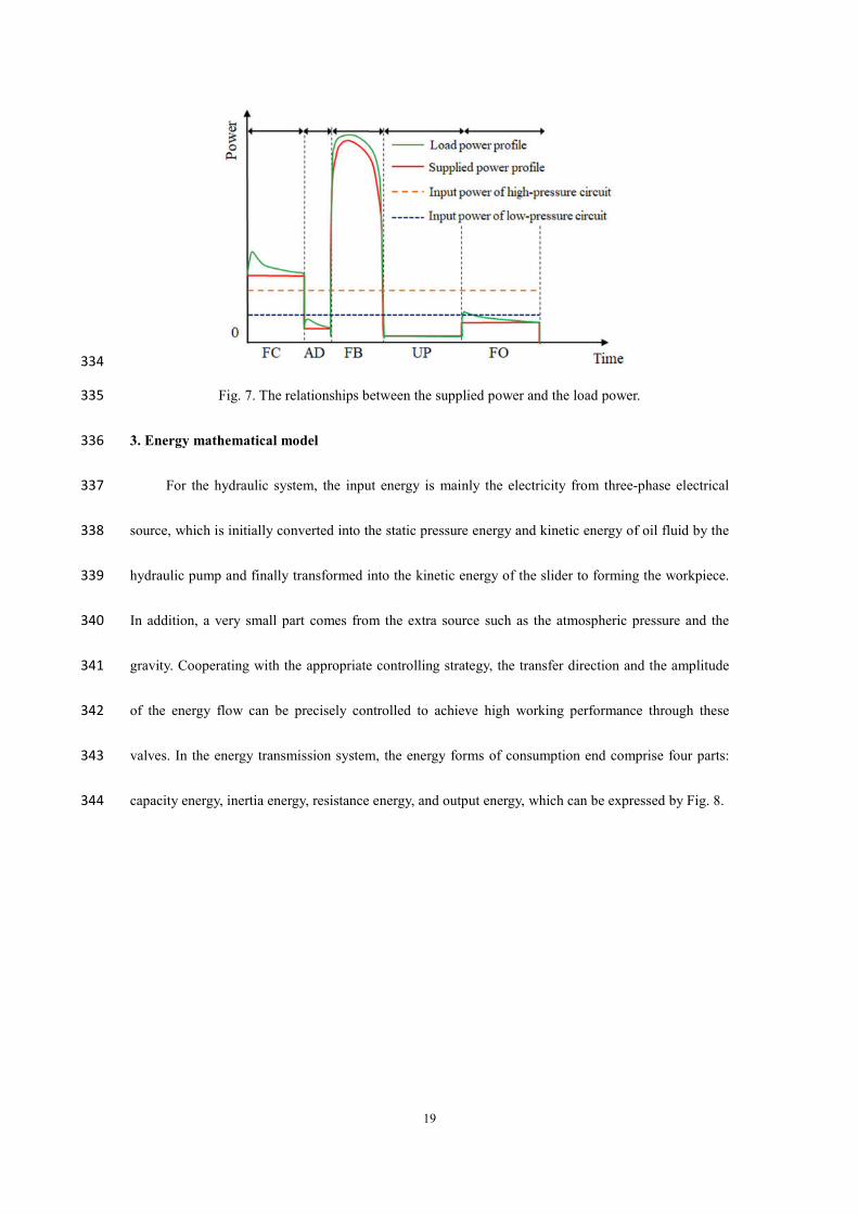
energy regulators. For the low- press circuit, the power supply unit is the ordinary motor with fixed 312
displacement pump, which belongs to constant output flow system. During the FC, AD, UP, FO Stages, 313
the system load mainly comes from the gravity of the slider. In addition, the movement speed of each 314
stage is constant. Hence, the load power of each stage is also constant. Generally, there are two 315
different methods to match this type of load power demand. The first one is to keep the appropriate 316
constant supply pressure for meeting the load pressure of different stages for reducing overflow of 317
energy consumption. However, this kind of method loses the advantages of the fast response speed, 318
which is unaccepted for the hydraulic fine blanking press. The second method is to adapt the 319
accumulator to regulate the power relationships between these stages, which is also able to increase the 320
system response speed. The input power of the low pressures circuit is lower than the load power of the 321
FA stages and higher than the load power of the AD, UP, FO stages. The function of the ordinary 322
accumulator is to absorb the extra energy of the AD, UP, FO stages and release the storage energy 323
during the FC stages, which is helpful to reduce the installed power of the motor in the low pressure 324
circuit. However because of the output pressure decreasing with the output oil of the ordinary 325
accumulator, at the beginning of draining stage, a peak supply power comes up and the output power of 326
the ordinary accumulator will decrease with the oil flow output constantly, Seen from the supplied 327
power profile in Fig. 7. As for the FB stage, the load power is super-high and changeable, which will 328
lead to great energy waste if adopting the ordinary accumulator. The controllable accumulator has four 329
working modes, which can adjust its output pressure to track the load power profile automatically. 330
Similar with the ordinary accumulator in the low pressure circuit, this controllable accumulator only 331
works in the FB stages and absorbs the extra energy during other stages. In all, the supplied power 332
should higher than the load power for ensuring the normal working of the fineblanking processing. 333
19
334
Fig. 7. The relationships between the supplied power and the load power. 335
3. Energy mathematical model 336
For the hydraulic system, the input energy is mainly the electricity from three-phase electrical 337
source, which is initially converted into the static pressure energy and kinetic energy of oil fluid by the 338
hydraulic pump and finally transformed into the kinetic energy of the slider to forming the workpiece. 339
In addition, a very small part comes from the extra source such as the atmospheric pressure and the 340
gravity. Cooperating with the appropriate controlling strategy, the transfer direction and the amplitude 341
of the energy flow can be precisely controlled to achieve high working performance through these 342
valves. In the energy transmission system, the energy forms of consumption end comprise four parts: 343
capacity energy, inertia energy, resistance energy, and output energy, which can be expressed by Fig. 8. 344

20
345
Fig. 8. Energy flow chart of hydraulic system. 346
In hydraulic system, there are amounts of oil chambers such as hydraulic accumulators, the 347
cylinder oil chambers, pipes chamber and the valve chambers, which can store the high-pressured oil. 348
In actual, the interaction relationship between these chambers and the main system is mutual. All these 349
storage energy will be released and returned to the main system. However, some capacity energy are 350
utilized for forming workpiece such as the hydraulic accumulator and some are wasted in the form of 351
thermal energy such as the high-pressured energy of the cylinder chamber. For the general oil chamber, 352
the capacitive power of the fluid volume can be computed as follows: 353
capacity chamber inflowP p q (1) 354
Pcapacity is the capacitive power of fluid volume. pchamber is the chamber pressure. qinflow is the 355
inflow oil into the chamber. 356
Similar to the electric capacitor, these chambers can function as energy storage and vibration 357
reduction, which is important to the working performance of the hydraulic system as well to the system 358
energy consumption characteristic. 359
21
Inertial energy is due to the motion of the body. For the hydraulic system, the most important 360
part is the oil fluid. The oil fluid contains two typed energy, which are the static pressure and kinetic 361
energy, respectively. For the machine, the proportion of these two type energy determines the working 362
mode of the power transmission system. For the hydraulic pressure system, the capacitive energy 363
accounts for the major. Relatively, the energy of hydrostatic system is transmitted by the inertial energy 364
of oil fluid. For the hydraulic system, the oil flows in the pips or the holes. Hence, the inertial of the 365
moving oil fluid can be calculated by Eq. (2): 366
2(1 )v
iner oil oil vmean comp
dQLP QS p r dt
(2) 367
L is the length of the pipe or hose. S is the cross section arear of the pipe or hose. Rcomp is the 368
radial wall compliance of the pipe or hose. pmean is the mean pressure of the pipe or hose. ρoil is density 369
at the mean pressure. Qv is the volumetric flow rate at the mean pressure. 370
In addition, for mechanical system, the piston moves with huge inertial energy, which can be 371
expressed by Eq. (3). 372
iner mechP m a v (3) 373
m is the body mass. a is the body acceleration. v is the body velocity. 374
In hydraulic system, the hydraulic components, such as the motor, the pump, the hydraulic 375
cylinder, the pipe, the hydraulic valve and the accumulator, are the basic elements of the hydraulic 376
system as well as the basic units of energy transmission and transformation. When high pressure oil 377
passes these hydraulic components, energy dissipation will be generated because of resistance effect. 378
Additionally, it should be pointed out that the 379
In Author Xu et al., (2019) , the motor loss pe, pump volume-mechanical loss ppump-loss, pipe local –380
rout loss ppipe-loss, valve throttling loss pvalve-loss, cylinder leakage loss pcylin-loss, and overflow loss poverf-loss 381

22
are expressed as follows. 382
21= ( )u
e nn
k pp p kp
(4) 383
1000(1 ) [1 (1 )( )]ps out
u v m up out f
ump lic
ossC q Tpp pn T T
(5) 384
2 2
2 2t t
pipe loss j f t tv vdp p p Q Q
l (6) 385
02( )1( sin 2 )sin ( )
2a b
valve loss c a bP Pp c d x P P
(7) 386
21 2( )cylin loss ic c j
dyp C p p B Adt (8) 387
overf loss s dp p q (9) 388
Hence, the total power loss Ploss-hydra of hydraulic system can be expressed by Eq. (10) 389
loss hydra e pump loss pipe loss valve loss cylin loss overf lossP p p p p p p (10) 390
For the body motion such as the piston and the slider, because of the friction and damping, some 391
energy will be dissipated and can be calculated by Eq. (11): 392
2loss mech friction dampP F v C v (11) 393
Hence, the total resistive power is : 394
resistive loss hydra loss mechP P P (12) 395
Based on the energy conservation law of an energy system, we can get Eq. (13): 396
electric sources capacity inertia resistive outputP P P P P P (13) 397
For the HFBP, the sources energy refers to the atmosphere pressure and the gravity. The 398
previous covers to all the components and the united force is zero at the same time. So it can be 399
ignored. The direction of the latter is down, which affects the relationship between the supplied 400
and the demanded power although the total input energy from the gravity source at one cycle is 401
zero considering the regular motion of piston and the slider of the machine. Hence, the Eq. (13) 402
can be simplified as Eq. (14): 403
23
electric gravity capacity inertia resistive outputP P P P P P (14) 404
405
4. Parameters design of two accumulator 406
In the proposed system, the most important part is to design the parameters of two 407
accumulators especially the controllable accumulator. Based on the requirements of the working 408
performance and the minimum energy consumption principle, the main parameters of this two 409
accumulators are calculated. 410
4.1 key parameters design of the ordinary accumulator 411
Actually, the ordinary accumulator cannot generate the extra oil. In the low-pressured 412
circuit, the total output oil volume from the low-pressured pump should fill the total volume of the 413
fast cylinder. Hence, the average output flow rate qm1 of the low-pressed pump in one cycle can be 414
calculated by Eq. (15): 415
1 1 2 2 5 51 5
1
= fast rod fast rodless fast rodless fast rodless fast rodm
ii
V V v A t v A t v A tq
T t
(15) 416
qm1 is the average output flow rate qm1 of the low-pressed pump (L/min). Vfast-rod and 417
Vfast-rodless are the rod chamber volume and the rodless chamber volume of the fast cylinder (L). 418
Afast-rod and Afast-rodless are the rod chamber volume and the rodless area of the fast cylinder (mm2). T 419
is the total time of each working cycle (s).vi (mm/s) and Δti (s) are the movement speed and time 420
interval of the slider during the FC, AD, FB, UP, FO stages, i[1,5]. 421
During the FC, AD and FO stages, the oil flow form the low-pressed pump is insufficient 422
to drive the high speed movement of the slider. Hence, the accumulator should provide the extra 423
oil flow to the fast cylinder and the effective working volume ΔV1 of this accumulator can be 424

24
calculated: 425
1 1 1 2 2 5 5 1 1 2 5( ) ( )fast rodless fast rodless fast rod mV v A t v A t v A t q t t t (16) 426
During the FB, UP and WT stages, all the input energy of the pump should enter the 427
accumulator ideally, which belongs to the capacity energy. Hence we can get following equation: 428
3 4 3 4
10 0
3 cos( ) - =0t t t t
capacityUI dt P dt
(17) 429
U (V) and I (A) are the input voltage and current of the electric motor, respectively. α1 is the 430
power factor of the motor; 431
On combining this with Eqs. (18)–(20): 432
03 4 6
0
1max1min1 min1
0 min10
[( ) 1]1
nt t tn
capacitypp VP dt
n p
(18) 433
0 0 001 01 min1 min1 max1 max1 1
n n np V p V p V c (19) 434
0 0
101 1 1
01 01
min1 max1
( ) ( )n n
VVp p
p p
(20) 435
p0, pmin, and pmax are the pre-charge pressure, minimum working pressure, and maximum working 436
pressure (bar) of the ordinary accumulator, respectively; n0 is the air polytropic exponent value; and V0 437
is the total volume of the ordinary accumulator (L). 438
In this study, the parameters p0, pmax, pmin, V0, and ΔV of the ordinary accumulator were 439
obtained as 90 bar, 170 bar, 190 bar, 16 L, and 0.5446 L, respectively in the 1000 ton fineblanking 440
press. 441
4.2 key parameters design of the controllable accumulator 442
The controllable accumulator only works in the FB stage and will provide huge oil flow to the 443
main cylinder during this stage. So the effective working volume of the controllable accumulator can 444

25
be calculated: 445
22 3 3 3main mV v A t q t (21) 446
For reducing the overflow dissipation, the controllable accumulator should be able to absorb the 447
output oil from other stages. Hence, the 2V should meet the condition: 448
22 ( 1, 2, 4,5)i mV t q i (22) 449
During these stages, the storage energy of this controllable accumulator is calculated by Eq. 450
(24): 451
1 2 4 5 6+
2 2 20
= 3 cos( )t t t t t
aE U I dt
(23) 452
U2 (V) and I2 (A) are the input voltage and current of the electric motor, respectively. α2 is 453
the .power factor of the motor. Ea is the storage energy capacity of the controllable accumulator. 454
For the controllable accumulator, the effective working volume consisting of two parts the main 455
accumulator and the gas regulator, and the total storage energy can be calculated by Eq.(24) and 456
Eq.(25), respectively. 457
0
1
2 022 02 2 1 02
02 max 2
(1 ) 1n
mm
V PV V V V VV P
, (24) 458
002 2
0
1
2 102 02
02 max 2
0 02
(1 )1
1
m
m nV V n
a x xV
VV PV PE P dV
n P
’
(25) 459
During the FB stage, the supplied energy from the motor and the controllable accumulator and the 460
demanded energy of the load should obey the energy conservation law based on the Eq.(14): 461
+electric a gravity inertia resistive loadE E E E E E (26) 462
In the Eq. (27), the important part is to determine the demanded energy of the load. Though the 463
analysis the forming process of the material, the fineblanking force is related to the fineblanking stroke 464

26
and can be expressed by Eq. (27). 465
max
2max
max2
45 108 6
( ) 19 ( ) 134 6
F x x XX
F xF x X
F X x XX
(27) 466
X is the thickness of the sheet metal. Fmax is the maximum fineblanking force. x is the stroke. 467
Hence, Eload can be expressed by Eq.(29): 468
3
1
2
1
3= ( ( )) ( )i
i
ii
t
load
t
E F x t v t dt
(28) 469
In this study, the parameters p0, pmax, pmin, V0, and ΔV of the controllable accumulator were 470
obtained as 100 bar, 230 bar, 190 bar, 16 L, and 12.100 L, respectively in the 1000 ton fineblanking 471
press. The gas regulator volume is 50.02 L. The maximum storage energy of the controllable 472
accumulator 760.72 kJ. 473
474
5. Case study 475
According to the schedumatic of the proposed system, a detailed hydrailic pricinple diagram 476
of 1000 ton hydraulic fineblanking press was designed as Fig .9. The whole diagram comprises 477
the fast cylinder circuit and the mian cylinder circuit. To avoid the unbalanced torque, there is four 478
fast cylinders installed on the symmetrical corner of the squrare slider. This circuit takes the servo 479
valve to achieve speed adjustment of the fast cylinder piston. The main cylinder is a single acting 480
cylinder with equipping fast charging function and pressre releasing function. The main cylinder is 481
installed on the center position of the slider shown as Fig. 10. 482

27
483
Y1,Y5- Hydraulic Pressure relief cartridge valve; Y2, Y6- Hydraulic Direction control cartridge 484
valve; Y3-Hydraulic Servo flow control valve; Y4-Hydraulic Direction control valve; Y7, Y10 - 485
Hydraulic ON/OFF valve; Y9- Servo flow control valve; Y10-Hydraulic ON/OFF valve; Y11- 486
Pneumatic ON/OFF valve; Y12- hydraulic pressure unloading valve. 487
Fig. 9. Detailed schedumatic of 1000 ton hydraulic fineblanking press. 488
489
Fig. 10. Assembely virtual structure of 1000 ton hydraulci dfneblanking press. 490
According to the pricinple diagram of 1000 ton hydraulic fineblanking press and the dynamic 491
model simulation model with energy comsumption analyzing function was built. Combined with 492
Matlab software, some complicated controlling strategyes such as the multiple stage PID for the 493

28
fast cylinder circuit and the Fuzzy PID controller for the controllable accumualtor can be achieved 494
with high precision. 495
496
Fig. 11. Simulation model of 1000 ton hydraulic fineblanking press 497
Seen from Fig. 11, the whole model comprises the main controller, fast-approaching cylinder 498
circuit module, main cylinder circuit module and the load module. In the load modlue, the 499
experiment fineblaking load was downnloaded and acted on the main cylinder circuit in the 500
simulation process. The Fuzzy PID controller for the controllable accumualtor was built on the 501
Matlab-Simulink as shown Fig. 12. 502

29
503
Fig. 12. Fuzzy PID controller shcematic for the controllable accumualtor . 504
For the 1000 ton hydraulic press, the main paprameters of the simulatiuon model was shown 505
as Table. 1. 506
Table 1. Main parameters in the simulation model. 507
Circuit Parameters Units Value
System parameters
FC stage stroke mm 60 AD stage stroke mm 10 FB stage stroke mm 10 FO stage stroke mm 80 One cycle duration s 2.9 Slide block weight and die kg 17500 Gravity value m/s2 9.81
Fast cylinder circuit
Motor speed r/min 1440 Motor power kw 40 Pump displacement cc/r 100 Accumulator volume L 16 Pipe diameter mm 32 Total pipe length mm 6800 Cylinder diameter mm 65
Circuit pressure MPa 16
Main cylinder circuit
Motor speed r/min 1440 Motor power kw 150 Pump displacement cc/r 250 Main accumulator volume L 100 Gas regulator volume L 50 Circuit pressure MPa 25 Main cylinder diameter mm 950

30
6. Results and discussion 508
The work load of the fineblanking press is 875 ton, which almost reach the maximum 509
working capacity of this machine. This section analyzes the new system form the aspect of 510
working performance and energy consumption. 511
6.1 Working performance analysis 512
The working performance and energy distribution of new system with controllable 513
accumulator was analyzed and some important indices concerning about the system performance 514
was compared with that of the traditional system, seen from Fig. 13 to 17. Actually, for the 515
fineblanking press process, the most important is to ensure the slider to move steadily and follow 516
the target signal accurately. Fig. 13 shows the slider displacement of new system and traditional 517
system. 518
0.0 0.5 1.0 1.5 2.0 2.5 3.00
10
20
30
40
50
60
70
80
Slid
er d
ispla
cem
ent/(
mm
)
Time/(s)
Traditional system New system Target signal
519
Fig. 13. Slider displacement of new system and traditional system. 520
Seen from Fig. 13, the time interval of each working cycle is 2.9 s in the new system, which 521
is 0.3s shorter than that of the traditional system. Hence, the production efficiency of the new 522
system is about 10% higher than that of the traditional system. During the FC stage, the slider 523
driven by the fast cylinder gradually gathered speed from 0 mm/s to 70mm/s. However, because of 524

31
the hysteresis characteristics of hydraulic system, the slider began to move up after 0.1s. Hence, 525
the displacement error between the new system and the target signal has the maximum value about 526
2.5 mm at the beginning of the FC stage and reduced with the time going seen from Fig. 14. When 527
it came into the AD stage, the decent rate of the displacement error increased and the displacement 528
error became comes into near 0 mm at the end of the AD stage seen from the red-line in Fig.14. 529
During the AD stage, the movement velocity of the slider is about 52.5 mm/s, which was well 530
consistent with the target velocity. Compared to the traditional system, the displacement error and 531
the velocity error of the slider of new system were much smaller than that of the traditional system. 532
In addition, the velocity fluctuation range of the slider of the new system was smaller, which is 533
helpful to reduce the pressure fluctuation while the slider came into the FB stage from the AD 534
stage. 535
At the beginning of the FB stages, the movement speed of the slider fluctuated a lot due to 536
the extra load from cutting the workpiece seen from Fig. 15. Because the movement velocity error 537
of the slider reached 30 mm/s which is bigger than the threshold value (20mm/s), the controllable 538
accumulator worked in the output flow mode for ensuring the slider velocity to keep up with 539
target velocity well. During this short time interval, the supplied pressure also fluctuated a lot with 540
the fluctuation of the velocity. The fluctuation duration of the movement speed was last for 0.3 s 541
and then kept at the value of 20 mm/s steadily during the whole FB stage. Correspondingly, the 542
working mode of the controllable accumulator was changed from the output flow mode to the 543
output pressure mode for tracking the load pressure. Seen from the Fig. 17, the supplied pressure 544
of the traditional system is about 230 bar, much higher than the load pressure, which would cause 545
great energy waste. However, in the new system, the supplied pressure can be adjusted to reduce 546

32
the pressure loss when the controllable accumulator worked in the output pressure mode. Hence, 547
the controllable accumulator can help the hydraulic system to achieve high energy efficiency by 548
controlling the output pressure. During the FB stage, the displacement error of the slider is below 549
0.5 mm, which is very important for ensuring high quality processing for cutting the material. 550
With the help of the controllable accumulator, the displacement and velocity of the actuator could 551
follow the target signal well. This verified that the controllable accumulator could work well on 552
the hydraulic fineblanking press and can greatly improve working performance. 553
The FO stage is designed to release the high pressure main cylinder bottom for the purpose 554
of opening the charge valve installed on the main cylinder. This process would last for 0.5 s 555
until the bottom pressure of the main cylinder reached to 0 bar, which made preparations fast 556
returning of the slider. As shown Fig. 13 and Fig. 15, the slider kept at the top point statically. 557
After this stage, the slider would return the initial point from the top point with high speed about 110 558
mm/s. Similar with the FC stage, there still have the hysteresis problem that the actual movement of 559
the slider was behind the target signal as shown in the Fig. 13 and 15. During the FO stage, the 560
displacement error changed from 4.8mm to 2.5 mm, which was much smaller than that of the 561
traditional system as shown Fig. 14. In addition, the velocity error was kept within a very small range 562
about 0.4mm except for the beginning and the end process of this stage as shown Fig. 16. 563

33
0.0 0.5 1.0 1.5 2.0 2.5 3.0
-20
-15
-10
-5
0
5
Slid
er d
ispla
cem
ent e
rror /
(mm
)
Time/(s)
Traditional system New system
564
Fig. 14. Slider displacement error of new system and traditional system. 565
0.0 0.5 1.0 1.5 2.0 2.5 3.0-120
-100-80-60-40-20
0204060
80100
Slise
r vel
ocity
/(mm
/s)
Time/(s)
Traditional system New system Target velocity
566
Fig. 15. Slider velocity of new system, traditional system and target signal. 567
568

34
0.0 0.5 1.0 1.5 2.0 2.5 3.0
-100
-50
0
50
100
Vel
ocity
erro
r/(m
m/s)
Time/(s)
1
2
3
4
Cont
rolla
ble
accu
mul
ator
wor
king
mod
e1-Output pressure mode2-Precharge pressure mode3-Output flow mode4-Output power mode
569
Fig. 16. Relationship between the velocity error and the working mode of controllable 570
accumulator. 571
0.0 0.5 1.0 1.5 2.0 2.5 3.00
50
100
150
200
250
Pres
sure
/(bar
)
Time/(s)
Traditional system supplied pressure New system supplied pressure Load pressure
572
Fig. 17. Load pressure and the supplied pressure of traditional system and the new system. 573
In all, compared to the additional system, the working performance of the new system was 574
improved a lot during each stage, especially in the FB stage. During this stage, the fluctuation 575
range of the displacement error and the velocity error were limited within 0.46 mm and 0.5 mm/s 576
respectively with the help of the controllable accumulator. Additionally, the production efficiency 577
of the new system was also increased by nearly 10% compared to the traditional system. 578
6.2 Energy dissipation analysis 579

35
According to theoretical analysis, the energy type of the whole system can be divided into 580
three types-resistive energy, capacitive energy and inertial energy. There are two hydraulic circuits 581
working in the hydraulic fineblanking press, which are the fast cylinder circuit and the main 582
cylinder circuit, respectively. The former can be taken as the valve-controlled system and three 583
types of energy were distributed as shown in Fig.18. 584
FC AD FB UP FO
-9
-6
-3
0
3
6
9
12
15
Ener
gy c
hang
e/(k
J)
Stages
Resistative Capacitive Intertial
585
Fig. 18. Energy change of resistive, capacitive and inertial energy of fast cylinder circuit. 586
Seen from Fig.18, the resistive energy reached 15.1 kJ during the FC stage, which finally was 587
converted into the thermal energy leading to the increasing temperature of the hydraulic oil. 588
Actually, most resistive energy was generated from the valve loss, motor loss and pump loss. 589
During this stage, the ordinary accumulator of the fast cylinder circuit released 7.6 kJ to 590
supplement the shortage of the pump resource. Hence, the captive energy was negative compared 591
to the initial status. Because the slider moved up, the gravitational potential energy of the system 592
was increased with the displacement. In addition, the kinetic energy of the slider was also 593
increased with the increasing of the velocity. This two parts lead to the inertial energy to be 594
increased to 7.2 kJ. The next stage, because of the short time duration of the AD stage, these three 595
types of energy was reduced to half of the FC stage. However, the velocity of the slider with huge 596

36
mass is decreased from 70 mm/s to 52.5 mm/s, which resulted in a more severe recession of the 597
inertial energy. When it came into the FB stage, most of energy about 9.1 kJ was consumed in the 598
form of the motor and pump loss after the ordinary accumulator was charged. Due to the reduction 599
of the slider velocity, the inertial energy change of the fast cylinder circuit was negative. Similarly, 600
the energy characteristic of UP stage in the fast cylinder circuit behaved the same trend with that 601
of the FB stage. During the last stage, the fast cylinder circuit drove the slider to move down with 602
a high speed, which resulted in the rapid declines of the inertial energy. Because of the valve loss, 603
the motor loss and pump loss, about 12.3 kJ resistive energy was generated. In all, the resistive 604
energy accounted for a big part of the total energy of each stage. Hence, it still has a great 605
potential to save some energy on the premise of ensuring meeting the normal working 606
requirements in the valve-controlled system. 607
FC AD FB UP FO
-75
-60
-45
-30
-15
0
15
30
45
Ener
gy c
hang
e/(k
J)
Stages
Resistative Compacitive Intertial
608
Fig. 19. Energy change of resistive, capacitive and inertial energy of main cylinder circuit. 609
The main cylinder circuit only worked in the FB stage. Hence, most energy was converted 610
and transformed during this stage. Seen from Fig.19, During the FC, AD, UP, FO stages, the 611
controllable accumulator was charged with little energy consumption as shown in Fig. 19. The 612
storage energy of the controllable accumulator was released for overcoming the load of 613

37
fineblanking the workpiece during the FB stage. It can be seen that the controllable accumulate 614
could change the release time and the size of the supplied energy according to the processing 615
requirements. This function of the controllable accumulator caused that the useful energy of the 616
FB stage is higher than the supplied energy from the power resource as shown in Fig. 20. However, 617
during the FB stage, the resistive energy reached 49.32 kJ due to the motor loss, pump loss and the 618
valve loss. Fig. 20 shows the comparison results of this two circuits about the input energy and 619
useful energy of each stage. The total input energy of the main cylinder circuit was about 164.1 kJ, 620
which was almost three times higher than that about 55.26 kJ of the fast cylinder circuit. The total 621
useful energy reached 100.8 kJ, most of which was located in the FB stage. Compared the 622
traditional system, the useful energy of them were almost the same. However, the huge difference 623
of the input between the new system and the traditional system lead to the huge difference of the 624
total energy efficiency as shown in Fig.21. The total input energy of the new system was about 625
219.3 kJ, which saved about 169.4 kJ energy compared the traditional system. Correspondingly, 626
the total energy efficiency of the new system was improved by 20.35% from 25.6% to 45.97%. 627
FC AD FB UP FO Total 0
20
40
60
80
100
120
140
160
Ener
gy/(k
J)
Stages
Fast cylinder circuit input enegry Main cylinder circuit input enegry Useful energy
628
Fig. 20. Energy input and useful energy of each stage in new system. 629

38
Traditional system New system0
50
100
150
200
250
300
350
400
45.97%
Ener
gy/(k
J)
Item
Total input enegry Useful enegry
25.62%
630
Fig. 21. Total input energy and useful energy efficiency of new system and traditional system. 631
632
7. Conclusion 633
To improve the work performance and the energy efficiency of the high-end hydraulic press, 634
a general hydraulic system with double-stage pressure circuit concept was studied form the aspect 635
of the processing requirements and the energy demand considering make full use of the 636
controllable accumulator. This new system was applied on the 1000 ton hydraulic fineblanking 637
press with the working load of 875 ton. Some significant conclusion about this new system can be 638
drawn as follows. 639
1) Compared to the traditional system, this new system shows better working performance. The 640
fluctuation range of the displacement error and the velocity error were limited within 0.46 mm and 641
0.5 mm/s respectively with the help of the controllable accumulator during the fineblanking stage. 642
This new system solved the huge pressure fluctuation problem while the driving force of the slider 643
was change with super high load by changing the working mode of the controllable accumulator. 644
In addition, the production efficiency of the new system is improved by 10% compared to the 645
traditional system. 646

39
2. Most energy is input by the main cylinder circuit and consumed in the fineblanking processing. 647
The total energy of the new system is decreased by 169.4 kJ electric energy compared to the 648
traditional system and the total energy efficiency of the new system was improved by 20.35% 649
from 25.6% to 45.97%. 650
In this study, the controllable accumulator is embedded into the hydraulic fineblanking press 651
and improves the working performance and energy efficiency of the machine greatly. Future work 652
will focus on the online energy monitoring of the hydraulic system with adopting some artificial 653
intelligence technology, which is significant to achieve the online energy optimization of the 654
forming machine. 655
656
Acknowledgements 657
The authors would like to thanks the Huangshi Huali Metal forming Machine Tool Co., Ltd for 658
providing the technology parameters. 659
Authors’ Contributions 660
LH was in charge of the whole trial; ZX wrote the manuscript and carried out the simulation; YL 661
assisted with the simulations; XZ was in charge of technical expression and language. 662
All authors read and approved the final manuscript. 663
Authors’ Information 664
Lin Hua, born in 1962, received his Ph.D. degree in Mechanical Engineering from Xi’an Jiaotong 665
University, China, in 2000. Dr. Hua is currently a Professor at the School of Automotive Engineering at 666
Wuhan University of Technology, China. Dr. Hua’s research interests include advanced forming and 667
equipment technology. 668

40
Zhicheng Xu, born in 1993, is currently a Ph.D candidate at School of Automotive Engineering at 669
Wuhan University of Technology, China. His research interests are green and smart manufacturing. 670
Yanxiong Liu, born in 1985, received Ph.D. degree from Wuhan University of Technology in 2012. 671
From 2010 to 2012, he did the research as a Research Scholar in Purdue University, and currently is an 672
Associated Professor in the School of Automotive Engineering. His research interests lie in the fields of 673
green and smart manufacturing. 674
Xinhao Zhao, born in 1989, is currently a Ph.D candidate at School of Material science and 675
engineering at Wuhan University of Technology, China. His research interests are green and smart 676
manufacturing. 677
678
Funding 679
The authors would like to thank the Fundamental Research Funds for the Central Universities 680
(WUT:501 2019Ⅲ117CG and 2020-YB-019), 111 Project (B17034), Innovative Research Team 681
Development Program of 502 Ministry of Education of China (No. IRT_17R83) and China Scholarship 682
Council, China (CSC, File, No.201906950038) for the financial supports given to this research. 683
Competing Interests 684
The authors declare no competing financial interests. 685
Author Details 686
1. Hubei Key Laboratory of Advanced Technology of Automotive Components, Wuhan University of 687
Technology, Wuhan, 430070, China. 688
2. Hubei Collaborative Innovation Center for Automotive Components Technology, Wuhan University 689
of Technology, Wuhan, 430070, China. 690

41
3. School of Materials Science and Engineering, Wuhan University of Technology, Wuhan, 430070, 691
China 692
4. Department of Mechanical Engineering, University of Wisconsin-Madison, Madison, WI 53706, 693
USA 694
695
Reference 696
[1] Gao M, Li L, Wang Q, et al. Energy Efficiency and Dynamic Analysis of a Novel Hydraulic 697
System with Double Actuator[J]. International Journal of Precision Engineering and 698
Manufacturing-Green Technology. 2020, 7(3): 643-655. 699
[2] Bhandari B, Lee K, Lee G, et al. Optimization of hybrid renewable energy power systems: A 700
review[J]. International Journal of Precision Engineering and Manufacturing-Green Technology. 2015, 701
2(1): 99-112. 702
[3] Mianehrow H, Abbasian A. Energy monitoring of plastic injection molding process running with 703
hydraulic injection molding machines[J]. Journal of Cleaner Production. 2017, 148: 804-810. 704
[4] Zhou L, Li J, Li F, et al. Energy consumption model and energy efficiency of machine tools: a 705
comprehensive literature review[J]. Journal of Cleaner Production. 2016, 112: 3721-3734. 706
[5] Yan X, Chen B, Zhang D, et al. An energy-saving method to reduce the installed power of 707
hydraulic press machines[J]. Journal of Cleaner Production. 2019, 233: 538-545. 708
[6] Hua L, Liu Y, Zhuang W, et al. Fineblanking technology and equipment[M]. Wuhan university of 709
technology press, 2015: 332-333. 710
[7] Xu Z, Liu Y, Hua L, et al. Energy analysis and optimization of main hydraulic system in 711
10,000 kN fine blanking press with simulation and experimental methods[J]. Energy Conversion and 712

42
Management. 2019, 181: 143-158. 713
[8] Lohse H, Weber J. Simulation-Based Investigation of the Energy Efficiency of Hydraulic Deep 714
Drawing Presses[J]. HIDRAVLICNA STISKALNICA(German). 2013, 2(19): 117-124. 715
[9] Xu Z, Liu Y, Hua L, et al. Energy analysis and optimization of main hydraulic system in 716
10,000 kN fine blanking press with simulation and experimental methods[J]. Energy Conversion and 717
Management. 2019, 181: 143-158. 718
[10] Zhao K, Liu Z, Yu S, et al. Analytical energy dissipation in large and medium-sized hydraulic 719
press[J]. Journal of Cleaner Production. 2015, 103: 908-915. 720
[11] Ho T H, Ahn K K. Design and control of a closed-loop hydraulic energy-regenerative system[J]. 721
Automation in Construction. 2012, 22: 444-458. 722
[12] H T, K A. Comparison and assessment of a hydraulic energy saving system for hydrostatic drives. 723
Proceedings of the Institution of Mechanical Engineers[J]. Part I: Journal of Systems and Control 724
Engineering. 2011, 1(225): 2134. 725
[13] Yao J, Li B, Kong X. Energy Saving and Control of Hydraulic Press Fast Forging System Based 726
on the Two-stage Pressure Source[J]. Journal of mechanical engnieering. 2016, 52(10): 199-206. 727
[14] Jing Y, Bin L, Yu S, et al. Study on Hydraulic Press Fast Forging Energy-saving and Control 728
System Based on Variable Frequency Adjustment[J]. China Mechanical Engineering. 2015(6): 729
749-755. 730
[15] Huang H, Zou X, Li L, et al. Energy-Saving Design Method for Hydraulic Press Drive System 731
with Multi Motor-Pumps[J]. International Journal of Precision Engineering and Manufacturing-Green 732
Technology. 2019, 6(2): 223-234. 733
[16] Li L, Huang H, Zhao F, et al. Analysis of a novel energy-efficient system with double-actuator for 734

43
hydraulic press[J]. Mechatronics. 2017, 47: 77-87. 735
[17] Wang H, Wang H, Zhu T. A new hydraulic regulation method on district heating system with 736
distributed variable-speed pumps[J]. Energy Conversion and Management. 2017, 147(147): 174-189. 737
[18] Xu Z, Liu Y, Hua L, et al. Energy improvement of fineblanking press by valve-pump combined 738
controlled hydraulic system with multiple accumulators[J]. Journal of Cleaner Production. 2020, 257: 739
120505. 740
[19] Zimmerman J D, Pelosi M, Williamson C A, et al. Energy consumption of an LS excavator 741
hydraulic system[J]. Proceedings of IMECE2007;2007 ASME International Mechanical Engineering 742
Congress and Exposition. 2007. 743
[20] Andrea B, Federico C, Mirko P, et al. Energy saving solutions for a hydraulic excavator[J]. Energy 744
Procedia. 2017, 126. 745
[21] Lovrec D, Kastrevc M, Ulaga S. Electro-hydraulic load sensing with a speed-controlled hydraulic 746
supply system on forming-machines[J]. The International Journal of Advanced Manufacturing 747
Technology. 2009, 41(11-12): 1066-1075. 748
[22] Ge L, Quan L, Zhang X, et al. Efficiency improvement and evaluation of electric hydraulic 749
excavator with speed and displacement variable pump[J]. Energy Conversion and Management. 2017, 750
150: 62-71. 751
[23] Yu Y, Ahn K K. Energy Regeneration and Reuse of Excavator Swing System with Hydraulic 752
Accumulator[J]. International Journal of Precision Engineering and Manufacturing-Green Technology. 753
2020, 7(4): 859-873. 754
[24] Dang T D, Do T C, Ahn K K. Experimental Assessment of the Power Conversion of a Wave 755
Energy Converter Using Hydraulic Power Take-Off Mechanism[J]. International Journal of Precision 756

44
Engineering and Manufacturing-Green Technology. 2020. 757
[25] Dang T D, Phan C B, Ahn K K. Design and Investigation of a Novel Point Absorber on 758
Performance Optimization Mechanism for Wave Energy Converter in Heave Mode[J]. International 759
Journal of Precision Engineering and Manufacturing-Green Technology. 2019, 6(3): 477-488. 760
[26] Yu Y, Ahn K K. Improvement of Energy Regeneration for Hydraulic Excavator Swing System[J]. 761
International Journal of Precision Engineering and Manufacturing-Green Technology. 2020, 7(1): 762
53-67. 763
[27] Jun G, Daqing Z, Yong G, et al. Potential energy recovery method based on alternate recovery and 764
utilization of multiple hydraulic cylinders[J]. Automation in Construction. 2020, 112: 103105. 765
[28] Ge L, Dong Z, Quan L, et al. Potential energy regeneration method and its engineering 766
applications in large-scale excavators[J]. Energy Conversion and Management. 2019, 195(195): 767
1309-1318. 768
[29] Chen Q, Lin T, Ren H, et al. Novel potential energy regeneration systems for hybrid hydraulic 769
excavators[J]. Mathematics and Computers in Simulation. 2019, 163: 130-145. 770
[30] Lin T, Wang L, Huang W, et al. Performance analysis of an automatic idle speed control system 771
with a hydraulic accumulator for pure electric construction machinery[J]. Automation in Construction. 772
2017, 84: 184-194. 773
[31] Yang Y, Li G, Zhang Q. A Pressure-Coordinated Control for Vehicle Electro-Hydraulic Braking 774
Systems[J]. Energies. 2018, 11(9): 2336. 775
[32] Mensing F, Li P Y. Sizing and Optimal Operation of a Power Split Hydraulic Hybrid Drive 776
Train[J]. Proceedings of the International Fluid Power Exhibition, Las, NV, USA. 2226. 2011. 777
[33] Wang R, Gu F, Cattley R, et al. Modelling, Testing and Analysis of a Regenerative Hydraulic 778

45
Shock Absorber System[J]. Energies. 2016, 9(5): 386. 779
[34] Chen Q, Yue X, Geng D, et al. Integrated characteristic curves of the constant-pressure hydraulic 780
power take-off in wave energy conversion[J]. International Journal of Electrical Power & Energy 781
Systems. 2020, 117: 105730. 782
[35] Pourmovahed A, Otis D R. An Experimental Thermal Time- Constant Correlation for Hydraulic 783
Accumulators[J]. Transactions of the ASME. 1990, 112(116): 113-120. 784
[36] Zhao W, Ye Q. Analysis of Dynamic Performance for New Double-bladder Accumulator[J]. 785
Chinese Hydraulic and Pneumatic. 2018(1): 96-103. 786
[37] Van D V, James D. Constant pressure hydraulic energy storage through a variable area piston 787
hydraulic accumulator[J]. Applied Energy. 2013(105): 262-270. 788
[38] Latas W, Stojek J. A new type of hydrokinetic accumulator and its simulation in hydraulic lift with 789
energy recovery system[J]. Energy. 2018, 153: 836-848. 790
[39] Liu Y, Xu Z, Hua L, et al. Analysis of energy characteristic and working performance of novel 791
controllable hydraulic accumulator with simulation and experimental methods[J]. Energy Conversion 792
and Management. 2020, 221: 113196. 793
794

Figures
Figure 1
The schedule of work processing and the movement of slider.

Figure 2
Simpli�ed diagram of main hydraulic system.

Figure 3
Schematic of the low-high pressured system controller.

Figure 4
Virtual assembly structure of controllable accumulator.
Figure 5

Hydraulic schematic of the controllable accumulator.
Figure 6
Principle of selector in the main controller

Figure 7
The relationships between the supplied power and the load power.

Figure 8
Energy �ow chart of hydraulic system.
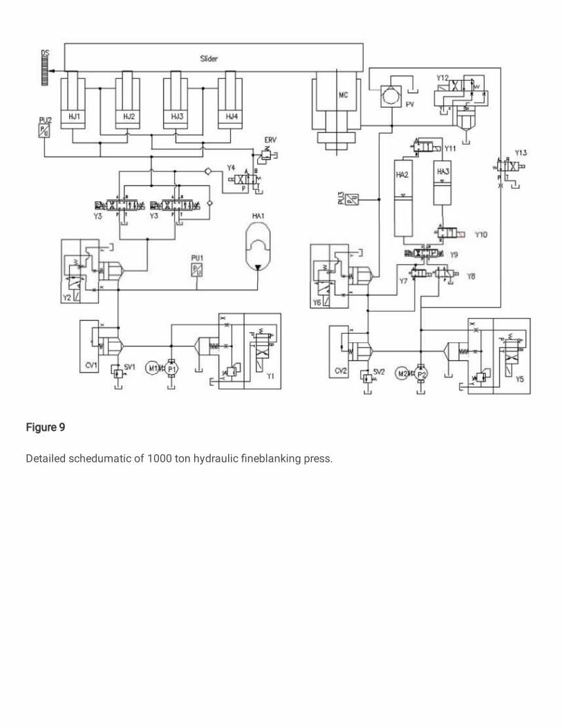
Figure 9
Detailed schedumatic of 1000 ton hydraulic �neblanking press.

Figure 10
Assembely virtual structure of 1000 ton hydraulci dfneblanking press.

Figure 11
Simulation model of 1000 ton hydraulic �neblanking press

Figure 12
Fuzzy PID controller shcematic for the controllable accumualtor.
Figure 13
Slider displacement of new system and traditional system.
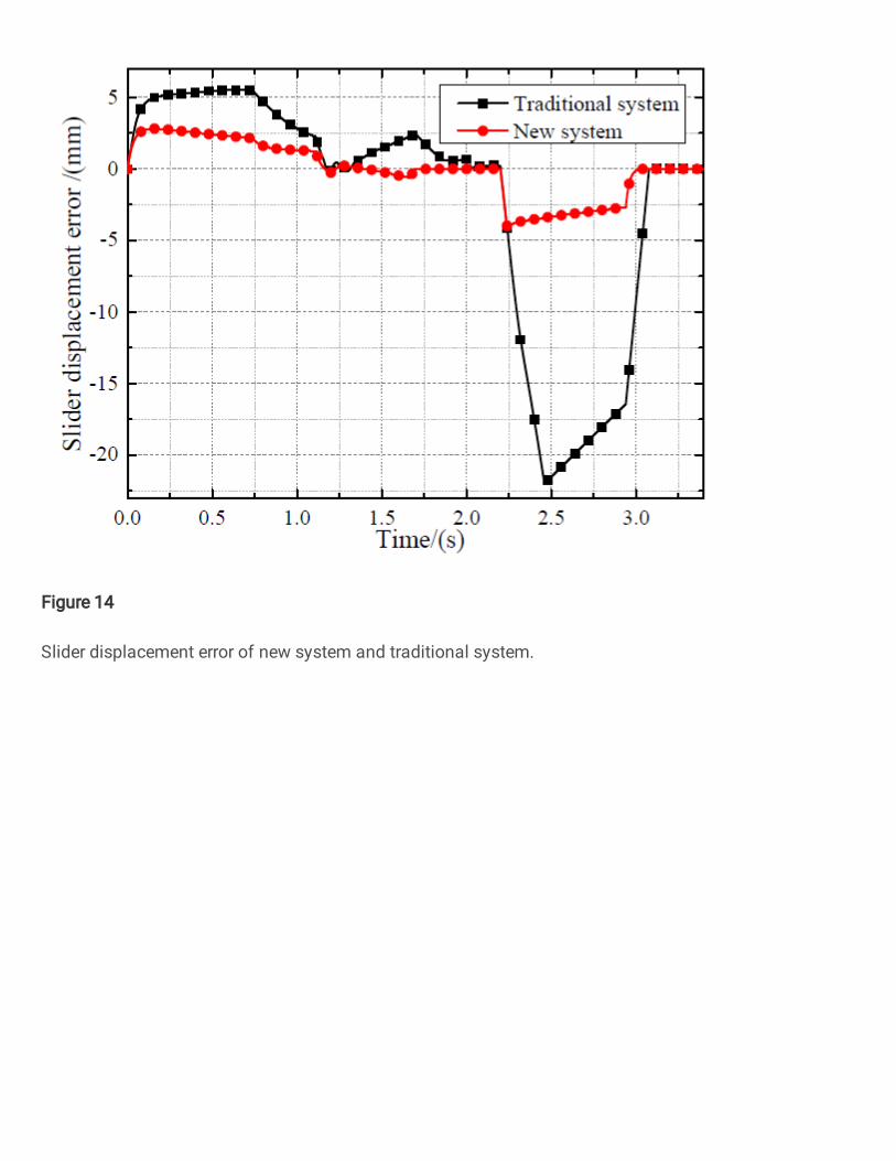
Figure 14
Slider displacement error of new system and traditional system.

Figure 15
Slider velocity of new system, traditional system and target signal.

Figure 16
Relationship between the velocity error and the working mode of controllable accumulator.

Figure 17
Load pressure and the supplied pressure of traditional system and the new system.

Figure 18
Energy change of resistive, capacitive and inertial energy of fast cylinder circuit.

Figure 19
Energy change of resistive, capacitive and inertial energy of main cylinder circuit.

Figure 20
Energy input and useful energy of each stage in new system.

Figure 21
Total input energy and useful energy e�ciency of new system and traditional system.