Embed Size (px)
Citation preview

WARY NACA- HSFilSru.
~195~ copyf~O “ RM L50C14
mu.~~wMAY z 91957 ? Q
RESEARCH MEMORANDUMFLIGHT MEASUREMENTS WITH THE DOUGLAS D-558-II
(BuAero No. 37974) RESEARCH AIRPLANE
STATIC LATERAL AND DIRECTIONAL STABILITY CHARACTERISTICS
AS MEASURED IN SIDESLII?S AT MACH NUMBERS UP TO 0.87
By S. A. Sjoberg
Langley Aeronautical LaboratoryLangley Air Force Base, Va.
CLASIFIEE D3UJ1JENT
+.?hls document cmtalns clas. itred mformmon
affecting me Natmr!al Dsfemeof the ZmtedStates Within the mming of the Es;,criage Act,uSC ‘0:31 and 32. Its trans!mss, m or the
mrevelat,m cf ,ts contents in my manner to anum”thcrized Per.,. is prch, b,t ed bj law,Infcrm. men s- classif~ed rmy be mn. ?.rted
,m’ ! I e r s mr, s m the m.,litary and naw.i&%, ‘ ser.,... ,f th, u“md states, amrcrr,atc
/ ‘$,,, ~c!vtlmr aff, v?rs and mnlcyeee :f Lb.>F.4Ua1
Y
-,.-v, mm .,,! wk.? haw: a les,lmat. lnt~restlb,,.,.. , Wd ,, r.)n,tod stat., ,It, z”,., ,f klmw”
l? Y1lLYm$ d>s:ret,m .b: cf .,eoss!t Y ,r.st klmf r“ 4 !-,’ r.% f.
NATIONAL ADVISORY COMMITTEEFOR AERONAUTICS
v WASHINGTON
May 19, 1950b ..... m—.—....

NACA RM L50C14
LiBRARYIUACA- HSFRscommmm
NATIONAL ADVISORY COMMITTEE FOR AERONAUTICS
RESEARCH MEMORANDUM
FLIGHT ~S WITH ‘THEDOUGLAS G55&II
(BuAero No. 37974) RESEARCH AIRPIANE
STATIC LATERAL
AS MEMWRED
AND DIRECTIONAL STABILITY CHARACTERISTICS
IN SmESLIPS AT MACH mms UPTO0.87
By S. A. Sjoberg
suMMARY
Flight measurements were made in sideslips of the static lateraland directional stalility characteristics of the Douglas D-558-II(BuAero No. 37974) research airplane. The directional stability of theairplane was positive in both the clean and landing conditions at alltest speeds. About 2° of rudder deflection were required to produce 1°of sideslip in both the clean and landing conditions. There was nodecrease in the effectiveness of the rudder in producing sideslip up tothe highest Mach nuniberreached (0.87). There was a considerable in-crease in dihedral effect with increase in normal-force coefficient;d8a/d~ increased from 1.0 at a normal-force coefficient of 0.10 to 3.1
at a normal-force coefficient of 0.90. At a constant value of normal–force coefficient the dihedral effect was the same in the landingcondition as in the clean condition.
INTRODUCTION
The National Advisory Committee for Aeronautics is conducting aflight research program utilizing the Douglas G55%II (BuAero No. 37974)research airplane. The Ik55&II airplanes were designed for flightresearch in the transonic speed range and were procured for the NACA ly
the Bureau of Aeronautics, Department of the Navy. The flight researchprogram currently being conducted with the BuAero No. 37974 airplaneconsists of determining the stability and control characteristics andthe aerodynamic loads acting on the wing and horizontal tail of theairplane from the stalling speed up to a maximum Mach number of

2 co-mm NACA RM L50C14
-.
about 0.90. This paper presents results obtained on the static lateralmd directional stability characteristics as measured in sideslips.Sideslip data are presented for the airplane in both the landingcondition and clean condition for a Mach number range from 0.27 to 0.87.References 1 and 2 present results which have been obtained during thepresent flight program on other aerodynamic characteristics of theD-558-II airplane.
AIRPIANE
.
The Douglas IW358-11 airplanes have sweptback wing and tailsurfaces and were designed for combination turbojet and rocket power.The airplane being used in the present investigation (BuAero No. 37974)does not yet have the rocket engine installed. This airplane is poweredsolely by a J-34+E-40 turbojet engine which exhausts out of the bottomof the fuselage between the wing and the tail. Photographs of theairplane are shown as figures 1 and 2 and ain figure 3. Pertinent airplane dimensio~slisted in table 1.
Both slats and fences are incorporated
three-view drawing is shownmd characteristics are
on the wing of the airplane.The wing slats can he locked in the closed position or they can beunlocked. When the slats are unlocked the slat position is a functionof the angle of attack of the airplane. Also, the slats on the leftand right wings are interconnected and therefore, at any time, have thesame position. A section of’the slat and the forward portion of thewing showing the motion of the slat with respect to the wing is shownin figure 4.
The airplane is equipped with an adjustable stabilizer but no meansare provided for trinmihg out aileron or rudder control forces. Noaerodynamic~alance or control–force booster system is used on any ofthe controls. Hydraulic dampers are installed on all control surfacesto aid in preventing any control+urface flutter. Dive brakes arelocated on the rear portion of the fuselage.
The variations of aileron and elevator position with control+rheelposition are shown in figures 5 and 6, respectively, and the variationof rudder position with right-rudder-pedal position is shown in figure 7.The friction in the aileron, elevator, and rudder control systems asmeasured on the ground under no load are presented in figures 8, 9,and 10. These friction measurements were obtained ly measuring thecontrol position and the control force as the control was deflectedslowly. The rates of control-surface deflection during the frictionmeasurements were sufficiently low so that the control forces resultingfrom the hydraulic dampers in the control system were negligible.
commm

I
N$CA FM L50C14 3
INSTRUMENTATION
Standard NACA recording instruments were installed in the airplaneto measure the following quantities:
AirspeedAltitudeElevato~ and aileron+heel forcesRudder pedal forceNormal, longitudinal, and transverse accelerationsRolling~ pitching, and yawing velocitiesSideslip angleStabilizer, elevator, rudder, left- and right+ileron, and
slat positions
Strain gages were installed in the airplane to measure wing andtail loads. The strair+yige deflections were recorded on an oscillograph.All instruments were synchronized by means of a common timer.
A free-+wiveling airspeed head was used to measure both static andtotal pressure. This airspeed head was mounted on a boom 7 feet forwardof the nose of the airplane. A vsne which was used to measure sideslip
angle was mounted below the same boom @ feet forward of the nose of2
the airplane. (See fig. 1.)
The left– and right+aileron positions were measured on bell cranksabout 1 foot forward of the ailerons and the slat position was measuredon the slat control cable in the fuselage. The stabilizer, rudder, andelevator positions were measured on the control surfaces. The elevatorposition presented in this paper is the average of two measured positions.One measuring point was 6 inches outboard of the vertical stabilizer andthe other 11 inches inboard of the tip of the horizontal tail measuredperpendicular to the airplane center line. In no case was the differencebetween the two measurements greater than 0.3°. Thus, for the airplaneflight conditions covered in this paper, the twist of the elevator withrespect to the horizontal stabilizer was sm.11. The elevator positionspresented were measured with respect to the stabilizer and the stabilizerposition was measured with respect to the fuselage center line. The slatposition as used in this paper is defined in figure 4 by the distance ds.
All control positions were measured perpendicular to the control hingeline.

AIRSPEED CALIBRATION
4 coItFIDmIAIl NACA RM L50C14
The calibration of the airspeed installation was accomplished inthe Mach number range from 0.30 to 0.70 by making tower passes. Thedetails of the tower=pass method of obtaining airspeed calibrationsare given in reference 3. In order to extend the calibration up to aMach nuniberof 0.90 the following procedure was used: The blockingerror due to the fuselage was assumed to be constant. For the coribi–nation of fuselage shape and airspeed-boom length used this assumptionis justified on the basis of results reported in reference 4. Theblocking error due to the airspeed head itself was established up to aMach nuniberof 0.85 from wind~unnel tests. By combining the constantblocking error of the fuselage with the blocking error due to theairspeed head, the airspeed calibration was extended up to a Machnumber of 0.85. For Mach numbers between 0.85 and 0.90 the calibrationwas extrapolated. The Mach numbers given in this paper are believedaccurate to +0.01.
TESTS, RESULTS, AND DISCUSSION
The static lateral and directional stability characteristics weremeasured in sideslips at various speeds with the airplane in both theclean and the landing configurations. With the airplane in the cleancondition (flaps up, gear up, slats locked, duct flaps closed), side-slips were made at five different Mach numbers in the range from 0.34to 0.87. In the landing condition (flaps down, gear down, slatsunlocked, duct flaps open), sideslips were made at indicated airspeedsof 158 and 182 tiles per hour. All of the data presented, except thatat a Mach number of 0.34 with the airplane in the clean condition, wereobtained as the sideslip angle was slowly increased. The data at aMach number of 0.34 were obtained at substantially constant sideslipangles. For the runs in which the sideslip angle was increasing, therate of change of the sideslip angle was between O.1° per second and0.4° per eecond. The data were obtained in the altitude range from13,000 to 21,000 feet.
Figure 11 shows the variations of rudder, total aileron, andelevator control positions and control forces and angle of bank withsideslip angle for the airplane in the clean condition. Sim,ilardatafor the airplane in the landing condition are shown in figure 12. Alsoincluded in figure 12 is the slat position.
The directional stability of the airplane was positive in both theclean and landi~ conditions at all test speeds. About 2° of rudderdeflection were required to produce 10 of sideslip in both the clean
colIETDmw

NACA RM L50C14 commm 5
and landing conditions, thus indicating nostability occurred in going from the clean
change in the directionalto the landing condition.
In figure 13 the slopes of the curves of rudder position against side-slip angle d5r/d~ from figure 11 are plotted as a function of Mach
number. The values of d~/d~ were measured for a sideslip+ngle
range of M?”. Up to the highest Mach nuniberreached (0.87), there hasbeen no decrease in the effectiveness of the rudder in producing side-slip since dbr/d~ is substantially constant up to this Mach nuniber.
The rudde-free directional stalility, as measured by the variation ofrudder pedal force with the sideslip angle, was positive for allconditions investigated.
The curves of aileron position against sideslip singlein figures 11and 12 show a considerable increase in dihedral effect with increase innormal-force coefficient. This increase is also shown in figure 14,where the variations of aileron angle with sideslip angle d5a/dp, as
obtained from figures 11 and 12, are plotted against normal-force coef-ficient. Data are included for both the clean and landing conditions.The values of d5a/dp were measured for a sideslip+ngle range of &o.
The dihedral effect d5a/d~ increases from 1.0 at a normal-force coef–
ficient of 0.10 to 3.1 at a normal-force coefficient of 0.90. Figure 14also shows that at a given normal-force coefficient the dihedral effectis the ssme in the landing condition as in the clesm condition.Figures 11 and 12 show that the pitching moment due to sideslip, asmeasured by the variation of elevator deflection required for trim withsideslip angle, is small for all conditions investigated.
Inspection of the control–force curves of figures 11 and 12 showsthat the curves are sonmtimes discontinuous near zero sideslip. Thediscontinuities are probably caused by the friction in the controlsystem. When the control forces due to the aerodynamic hinge momentsare large, this friction effect is masked. The slat-position measure–ments presented in figure 12 show that the slat position during the leftand right sideslips was not the same. The reason for the difference inslat positions is not known.
CONCLUDING REMARKS
Flight measurements were made in sideslips of the static lateraland directional stability characteristics of the Douglas D-558-II(BuAero No. 37974) research airplane. The directional stability of theairplane was positive in both the clean and landing conditions at alltest speeds. About 2° of rudder deflection were required to produce 1°of sideslip in both the cleem and landing conditions. There was no
6 coin’IllENTIA,L NACARML50C14
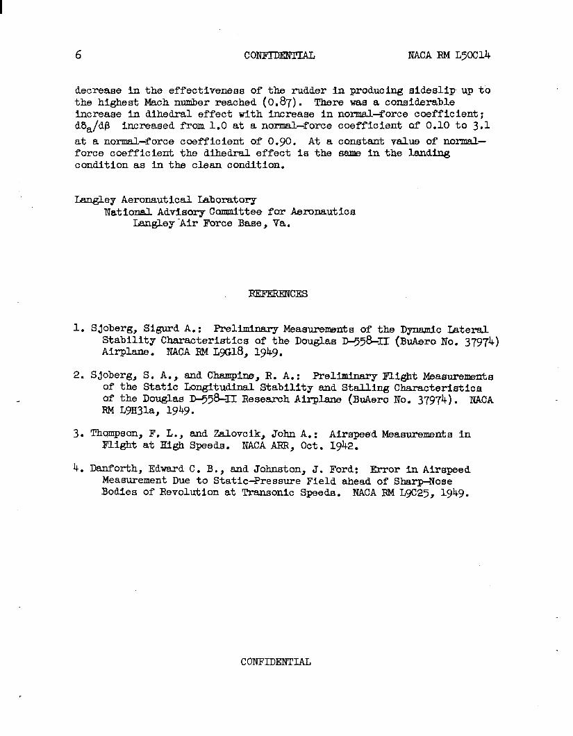
decrease in the effectiveness of the rudder in producing aideslip up tothe highest Mach number reached (0.87). There was a considerableiqcrease in dihedral effect with increase in norms.l=forcecoefficient;d5a/dP increased from 1.0 at a normal-force coefficient of 0.10 to 3.1
at a normal-force coefficient of 0.90. At a constant value of normal-force coefficient the dihedral effect is the sama in the landingcondition as in the cleam condition.
Lsz@ley Aeronautical Laborato~National Advisory hnmittee for Aeronautics
Langley Air Force Base, Va.
IxEmRENcEs
1. Sjoberg, Sigurd A.: Preliminary Measurements of the Dynamic LateralStability Characteristics of the Douglas ~~&I (BuAero No. 37974)Airplane . NACARML5G18, 1949.
2. Sjoberg, S. A.= and Champi~, R. A.: Preliminary Flight Measurementsof the Static Longitudinal Stability and Stalling Characteristicsof the Douglas ~58+CI Research Airplane (BuAero No. 37974). NACARM L9H31a, 1949.
3. Thcvnpson,F. L., and Zalovcik, John A.: Airspeed lleasmemefis inFlight at High Speeds. NACAARR, Oct. 1942.
4. Danforth, Edward C. B., and Johnston, J. Ford: Error -AirspeedMeasurement Due to Static+ressure Field ahead of Sharp-NoseBodies of Revolution at Transonic Speeds. NACARM L9CZ?’j,1949.
CONFIDENTIAL

NACA RM L50C14 CONFIDENTIAL
TABLE 1
DIMENSIONS AND CHARACTERISTICS OF THE
DOUGLAS ~558-11 AIRPLANE
Wing:Root airfoil section (normal to 0.30 chord)Tip airfoil section (normal to 0.30 chord)
Totalarea, sqft . . . . . . . . . . . . .Span,ft . . . . . . . . . . . . . . . . .
. Mean aerodynamic chord, in. . . . . . . . .Root chord (parallel to plane of symmetry),
●
✎
✎
✎
✎
.
.
●
✎
●
in.
Tip chord (parallel to plane of symmetry), in.Taper ratio. . . . . . . . . . . . . . .Aspect ratio . . . . . . . . . . . . . .Sweep at 0.30 chord, deg . . . . . . . .Incidence at fuselage center line~ deg .Dihedral, deg. . . . . . . . . . . . . .Geometric twist, deg . . . . . . . . . .Total aileron area (aft of hinge), sq ftAileron travel (each), deg . . . . . . .Total flaparea, sqft . . . . . . . . .Flap travel, deg . . . . . . . . . . . .
Horizontal tail:
●
✎
✎
✎
✎
●
✎
✎
●
✎
Root airfoil section (normal to 0.30 chord)Tip airfoil section (normal to 0.30 chord)Area (including fuselage), sq ft . . . . .Span, in.. . . . . . . . . . . . . . . . .Mean aerodynamic chord, in. . . . . . . . .Root chord (parallel to plane of symmetry)Tip chord (parallel to plane of symmetry)Taper ratio . . . . . . . . .Aspect ratio . . . . . . . .Sweep at 0.30 chord line, degDihedral, deg . .Elevator area, sqElevator travel
Up, deg . .Down, deg .
. .
● ☛
k“
● ..*
9
.
●
.
. .
. .
. .
. .
.
.
.
.
..
●
●
✎
✎
✎
●
✎
✎
✎
✎
✎
●
.
●
●
✎
✎
✎
✎
.
●
✎
✎
✎
✎
✎
.●
✎
✎
✎
✎
✎
.
.
●
✎
✎
✎
✎
●
✎
✎
●
✎
✎
✎
✎
.
.
.
●
✎
✎
✎
✎
●
●
✎
✎
✎
✎
●
✎
●
✎
✎
✎
●
✎
✎
✎
.
.
.
●
●
●
●
✎
✎
✎
●
✎
✎
●
✎
✎
✎
✎
✎
✎
✎
●
✎
✎
●
✎
✎
✎
●
✎
✎
✎
●
✎
✎
✎
●
●
✎
✎
✎
✎
✎
✎
✎
✎
●
✎
●
✎
✎
●
●
●
✎
.
●
✎
✎
✎
✎
✎
✎
●
✎
✎
●
✎
✎
✎
●
✎
✎
✎
✎
✎
✎
✎
✎
✎
✎
●
✎
✎
●
✎
.
.
●
✎
✎
✎
✎
✎
✎
✎
✎
✎
✎
●
✎
✎
✎
✎
✎
✎
✎
✎
✎
✎
✎
✎
✎
✎
●
✎
✎
●
✎
●
✎
✎
●
✎
✎
✎
✎
✎
✎
✎
●
✎
●
✎
✎
✎
✎
●
✎
✎
✎
✎
✎
●
✎
✎
✎
✎
7
. NACA 63~10
.NACA 631Q12
.
●
●
●
✎
✎
●
✎
✎
●
✎
✎
●
●
●
●
✎
✎
✎
✎
●
✎
✎
✎
✎
✎
✎
✎
●
.
●
✎
✎
✘
✎
✎
✎
✎
✎
●
✎
✎
✎
●
. 175.025.0
: 87.301108.508
: 61.N30. 0.565. 3● 570. 35.0.. –;::●
. 9.:
. ti5
. 12.58
. 50
NACA 63a10NACA 63~10.
●
●
✎
●
✎
✎
✎
●
●
✎
✎
.
●
✎
●
✎
✎
✎
✎
●
✎
.
.
39.9143.641.7553.626.80.503.5940.0
9.:
2515

8 CONFIDENTIAL
TABLE 1 - Concluded
DIMENSIONS AND CHARACTERISTICS OF THE
DOUGLAS D-558-II AIRPLANE - Concluded
Vertical tail:Airfoil section (parallel to fuselage center line).Area, sqft. . . . . . . . . . . . . . . . . . . .Height from fuselage center line, in. . . . . . . .Root chord (parallel to fuselage center line), in.Tip chord (parallel to fu:Sweep angle at 0.30 chord,Rudder area (aft of hingeRudder travel, deg . . .
Fuse,lage:Length, ft.......Maximum diameter, in. . .Fineness ratio . . . . .
elage center line),deg . .
line), sq. .
. .
. .
. .Speed–retarder area, sq ft .
Power plant . . . . . . . . . .
Airplane weight (full fuel), lbAirplane weight (no fuel), 11 .
.
.
●
●
✎
✎
✎
✎
.
.
.
.
●
✎
✎
●
●
●
●
●
✎
✎
✎
●
& “. .
. .
. ..0
. .
.0
. .
. .
.
.
.
.
.
●
✎
✎
●
✎
Airplane weight (full fue~ and 2 jatos), lb
.
.●
✎
●
✎
●
✎
●
✎
✎
.
●
✎
●
✎
✎
✎
●
●
✎
✎
in...
.
.
●
✎
●
✎
✎
✎
✎
Center-of+ravity locations:Full fuel (gear down), percent mean aerodynamic
9
.
●
●
●
.
●
.
.
.
.
.
●
✎
✎
✎
●
.
.
.
.
.●
●
✎
✎
✎
✎
✎
✎
.
.
.
.
.
.●
●
●
●
✎
✎
●
NACA RM L50C14
.
.
.
.
●
●
●
✎
✎
✎
●
●
✎
.
.
.
●
✎
✎
✎
✎
●
✎
✎
NACA 63~10. 36.6. 98.0. 146.o● 44.0● 49.0. 6.15
. 42.0● 60.0. 8.40● 5.25
.*..
.*O.
. . . .
chord .Full fuel (gear up), percent mean aerodynamic chord . .No fuel (gear down), percent mean aerodynamic chord . .No fuel (gear up), percent mean aerodynamic chord . . .Full fuel and 2 Jatos (gear down), percentmeanaerodynamic chord . . . . . . . . . . . . . . .
. .
. .
● ☛
● ✎
✎ ✎
✎ ✎
✎ ✎
● ✎
●
✎
●
●
✎
✎
●
●
2 Jatos for take-off10,6459,085
11,060
25.325.826.827.5
29.2
CONFIDENTIAL

NACA RM L50C14 CONFIDENTIAL 9
CONFl_DINTIAL

NACA RM L50C14 CONFIDENTIAL 11
CONFIDENTIAL

LIBRAHY NACA - HSFKS
NACA RM L50C14 coNl?IDmIAL
I
125Z4° I
?50“ ?
I
*
—.
-3”DIHEDRA[ IN
A34”
Figure 3.- Three-view drawing of the Douglas D-558-II (BuAero No. 37974)research airplane.

14 ‘ CONFIDENTIAL NACA ‘RM L50C14
T
~~iy Opuf
Slu?’ c/os& d - .-/--’-In+ posltlon~ +, :6.5 7_-— -—---
~
sA7tfu//y--
K
open///
// ///
// // / ,/’
/ / ,/// .<
/ ,’/
./ \_ P07%O;,SW,/
(\ /(,/‘=.=J/
~CU/Q + “‘
Figure 4.- Section of wing slat of Douglas D-558-II (BuAero No. 37974)research airplane perpendicular to leading edge of wing.
/II
CONFIDENTIAL

NACA RM L50C14 CONFIDENTIAL 15
.
II
-. -.. . .- , 1 I 1 I IH3ffTi_50 0 Jo
I I I
/002!!ZZ71/30 260
Counterc /ochwIse c/ock wiseControl- whee/ position , deg from neutru~
Figure ‘j.- Variation of left- and right-aileron positions with control-wheel position. No load on system.
CONFIDENTIAL

16 CONFIDENTIAL NACA RM L50C14
forward ReurwordContro/- wheel powtjon, vz from neutrul
Figure 6.- Variation of elevator position with control-wheel position.No load on system.
CONFIDENTIAL

NACA RM L50C14 CONFIDENTIAL
30
20 ‘
/
/0’
0’
/0
20 {
v304
2 0 2 4Rearword forwurd
/Q/ght-)’-uddQr- /oedo/ postion,n from ne utrd
17
Figure 7.- Variation of rudder position with right-rudder-pedal position.No load on system.
coNFIDmIAL

18 CONFIDENTIAL NACA RM L50C14
T
10
0
10
20 /0 o /0 20
Down up
Righf- aileron posifion, deg
Figure 8.- Aileron control force required to deflect ailerons on
.,(’
the ground under no load.
CONFIDENTIAL

NACA RM L50C14 CONFIDENTIAL 19
,.+
,
.
i
CA
CONFIDENTIAL

20 CONFIDENTIAL NACA RM L50C14
40
20 10 0 /0
Left Righ+Rudder posi?ion, deg
Figure 10.- Rudder control force required to deflect rudder onunder no load.
20
the ground
CONFIDENTIAL

NACA RM L50C14 CONFIDENTIAL 21
:$ 1--1--1Ill b-kf=l-lQ&l o
L
b
-8
left RlghtS/dQ.S//p anghi , deg
(a) Vc = 177 miles per hour; M = 0.34; CN = 0.73;stabilizer setti% 1.7° leading edge uP;engine power, 11,000 rpm.
Figure 11.- Sideslip characteristics of the Douglas D-558-II(Btiero No. 37974) resesmh airplane. Flaps up; gear up;slats locked; duct flaps closed.
CONFIDENTIAL

22 CONFIDENTIAL NACA RM L50C14
L- 1>~> I I I I I . Lu___
1
84048/2Left Rlgh?
S/de.siD angie,deg
(b) Vc = 213 miles per
1.7° leading
hour; M = 0.40; CN = O.~; stabilizer setting,
edge up; engine power, 11,000 rpm.
.
Figure 11.- Continued.
CONFIDENTIAL

NACA RM L50C14 CONFIDENTIAL 23
.
20
/0
o— — — —
/0
20
-R
40— —
o— —
L
46 ,P
❑ Ruo’dQr0 ~ofu/ Q//gyono /=/Q Vff tc2/-
/0 CL
0
\
0 — —
@,~ ,.-/’ w“ n
84048Leff /?/ght
Sldesllp angle. ~ deg
(c) Vc = 330 miles per hour; M = 0.60; CN = O.20; stabilizer setting,
1.8° leading edge up; engine power, 11,400 rpm.
Figure 11.- Continued.
CONFIDENTIAL “

CONFIDENTIAL NACA RM L50C14
2q
200
.3001
(d) Vc = khO miles per
1.7° leading
a ~u~de/-0 To~a/ a//eron
OE/evafo~ M
Left R/ghtS/des/ip angle, deg
hour; M = 0.78; CN = 0.12; stabilizer setting,
edge up; engine power, 12,300 rpm.
Figure 11.- Continued.
CONFIDENTIAL
.

NACA RM L50C14 2’j
❑ Ruddero Total aiiervnQE/e vutor
Left /Q/9f7+ -Sideshp angie , deg
(e) V= = 494 miles per hour; M = O.87; CN = O.10; stabilizer setting,
1.8° leading edge up; engine power, 12,500 rpm.
Figure 11.- Concluded.
.CONFIDENTIAL

26 CONFIDENTIAL NACA RM L50C14
[ eft RightS/d(zs/lp Ot7q/Q , dQg
(a) Vc = 158 miles per hour; M = 0.27; CN =
stabilizer setting, 1.9° leading edge
o. 91;up;
engine power, 11,400 rpm.
Figure 12.- Sideslip characteristics of(BuAero No. 37974) research airplane.slats unlocked; duct flaps open.
CONTIDENTIW
the Douglas D-558-IIFlaps down; gear down;

NACA RM L50C14 CONFIDENTIAL 27
❑ Ruddero Totol o//Qron
u 10 1 1 I(W
Jfi I1 1 1 wI
SIdasllp
(b) Vc = 182 miles per hour; M = O.34;
1.9° leading edge up; engine
o 8R;h t
Ongk , dizq
CN ~ 0.71; stabilizer setting,
power, 11)400 rpm.
Figure 12.- Concluded.
CONFIDENTIAL

28 CONFIDENTIAL NACA RM L50C14
4.0
2.0 c1
0.0 .2 .4 .6 .8 /.0
McIch number “
Figure 13. - Variation of d&-/dP with Mach number M as measuredin sideslips with the Douglas D-5~-11 (BuAero No. 37974) researchairplane. Flaps up; gear up; slats locked; duct flaps closed.
CONFIDENTIAL
.

NACA RM L50C14
,.
(.
CONFIDENTIAL 29
0 .2 .4 .6 .8 /.0Normal-force coefficient, CN
Figure 14.- Variation of d~~dfl with normal-force coefficient CN
as measured in SideSlips with the Douglas D-5~-11 (BuAero No. 37974)research airplane. ‘
,
CONFIDENTIAL
NACA-Langley -5-19-50-225