Embed Size (px)
Citation preview

NASA/CR—2001-210939 ARL-CR-462 OS. ARMY
RESEARCH LABORATORY
Modeling, Modal Properties, and Mesh Stiffness Variation Instabilities of Planetary Gears
Robert G. Parker and Jian Lin Ohio State University, Columbus, Ohio
DISTRIBUTION STATEMENT A Approved for Public Release
Distribution Unlimited
20010720 068
May 2001
The NASA STI Program Office ... in Profile
Since its founding, NASA has been dedicated to the advancement of aeronautics and space science. The NASA Scientific and Technical Information (STI) Program Office plays a key part in helping NASA maintain this important role.
The NASA STI Program Office is operated by Langley Research Center, the Lead Center for NASA's scientific and technical information. The NASA STI Program Office provides access to the NASA STI Database, the largest collection of aeronautical and space science STI in the world. The Program Office is also NASA's institutional mechanism for disseminating the results of its research and development activities. These results are published by NASA in the NASA STI Report Series, which includes the following report types:
• TECHNICAL PUBLICATION. Reports of completed research or a major significant phase of research that present the results of NASA programs and include extensive data or theoretical analysis. Includes compilations of significant scientific and technical data and information deemed to be of continuing reference value. NASA's counterpart of peer- reviewed formal professional papers but has less stringent limitations on manuscript length and extent of graphic presentations.
• TECHNICAL MEMORANDUM. Scientific and technical findings that are preliminary or of specialized interest, e.g., quick release reports, working papers, and bibliographies that contain minimal annotation. Does not contain extensive analysis.
• CONTRACTOR REPORT. Scientific and technical findings by NASA-sponsored contractors and grantees.
• CONFERENCE PUBLICATION. Collected papers from scientific and technical conferences, symposia, seminars, or other meetings sponsored or cosponsored by NASA.
• SPECIAL PUBLICATION. Scientific, technical, or historical information from NASA programs, projects, and missions, often concerned with subjects having substantial public interest.
• TECHNICAL TRANSLATION. English- language translations of foreign scientific and technical material pertinent to NASA's mission.
Specialized services that complement the STI Program Office's diverse offerings include creating custom thesauri, building customized data bases, organizing and publishing research results . . . even providing videos.
For more information about the NASA STI Program Office, see the following:
• Access the NASA STI Program Home Page at http://zviviv.sti.nasa.gov
• E-mail your question via the Internet to [email protected]
• Fax your question to the NASA Access Help Desk at 301-621-0134
• Telephone the NASA Access Help Desk at 301-621-0390
• Write to: NASA Access Help Desk NASA Center for AeroSpace Information 7121 Standard Drive Hanover, MD 21076

NASA/CR—2001-210939 ARL-CR-462
U.S. ARMY
RESEARCH LABORATORY
Modeling, Modal Properties, and Mesh Stiffness Variation Instabilities of Planetary Gears
Robert G. Parker and Jian Lin Ohio State University, Columbus, Ohio
Prepared under Grant NAG3-1979
National Aeronautics and Space Administration
Glenn Research Center
May 2001
Acknowledgments
The authors would like to thank Timothy L. Krantz of the Army Research Laboratory at NASA Glenn Research Center for his support and advice on the project.
Available from
NASA Center for Aerospace Information 7121 Standard Drive Hanover, MD 21076
National Technical Information Service 5285 Port Royal Road Springfield, VA 22100
Available electronically at http: / /gltrs.grc.nasa.gov/GLTRS

TABLE OF CONTENTS
1. Introduction 1
1.1 Motivation 1
1.2 Critical Topics 5
1.3 Scope of Investigation 12
2. Planetary Gear Modeling 15
2.1 Modeling Considerations 15
2.2 System Equations 17
3. Natural Frequency and Vibration Mode Properties 19
3.1 Equally Spaced Planets 19
3.2 Arbitrarily Spaced Planets 24
3.3 Modal Strain and Kinetic Energy 25
3.4 Discussion 27
4. Eigensensitivity to Design Parameters 33
4.1 Calculation of Eigensensitivity 34
4.2 Eigensensitivity to Mesh and Support Stiffnesses 37
4.2.1 Tuned System 37
4.2.2 Mistimed System 42
4.3 Eigensensitivity to Gear Mass and Inertia 45
4.4 Eigensensitivity to Operating Speed 47
4.5 Natural Frequency Veering 49
4.5.1 Veering/Crossing Criterion 50
4.5.2 Veering Rules in Planetary Gears 52
4.6 Discussion and Summary 55
5. Parametric Instability from Mesh Stiffness Variation 59
5.1 Two-Stage Gear Systems 60
5.1.1 System Model 60
NASA/CR—2001-210939 üi

5.1.2 Conditions of Parametric Instability 64
5.1.3 An Example 76
5.1.4 Discussion 77
5.2 Planetary Gears 79
5.2.1 System Model 82
5.2.2 General Expression for Instability Boundaries 85
5.2.3 Planetary Gear Parametric Instability 88
5.2.4 Tooth Separation Nonlinearity 97
6. Summary and Future Work 101
6.1 Summary and Benefits 101
6.2 Future Work 104
Appendix
A. System Matrices 109
B. Example System Ill
Bibliography 113
NASA/CR—2001-210939 iv

CHAPTER 1
INTRODUCTION
1.1 Motivation
Planetary gears are widely used in the transmissions of helicopters, automobiles,
aircraft engines, heavy machinery and marine vehicles. Figure 1.1 illustrates a single-
stage planetary gearset consisting of a sun gear, a ring gear, several planets, and a carrier.
Any of the carrier, ring, and sun can be selected as the input or output component, and the
power is transmitted through multiple paths of the planet meshes. Planetary gears have
substantial advantages over parallel shaft drives, including compactness, large torque-to-
weight ratio, diminished loads on shafts bearings, and reduced noise and vibration due to
the relatively smaller and stiffer components.
Despite planetary gears' advantages, noise and vibration remain major concerns in
their applications. In most helicopters, planetary gears are used in the last stage of gear
reduction. This planetary gear is mounted directly to the helicopter cabin, so its vibration
is the main source of structure-borne cabin noise, which can exceed 100 dB (Krantz,
1993). Measurement of the cabin noise shows that gear mesh frequency and its harmonics
are the dominant acoustic frequencies (Figure 1.2). Extensive cabin noise results in
NASA/CR—2001-210939

RING GEAR
PLANET CARRIER
PLANET QEAR
Figure 1.1 Planetary gear diagram (Lynwander, 1983)
Apache Helicopter Cockpit Noise
o
-10
-20 Relative SPLdB -30
re 20 jtPa -40
-50|-
-60
-70
Takeoff at maximum continuous oow«r
W^ I j (C + P4) p.
nr vwV SB / '
p - c - SB -
Planetary gear Combining gear Spiral Bevel
2 3 4
Frequency, kH2
Figure 1.2 Helicopter cabin noise spectra (Heath and Bossier, 1993)
NASA/CR—2001-210939
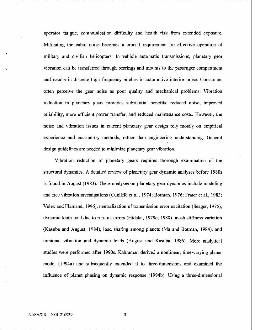
operator fatigue, communication difficulty and health risk from extended exposure.
Mitigating the cabin noise becomes a crucial requirement for effective operation of
military and civilian helicopters. In vehicle automatic transmissions, planetary gear
vibration can be transferred through bearings and mounts to the passenger compartment
and results in discrete high frequency pitches in automotive interior noise. Consumers
often perceive the gear noise as poor quality and mechanical problems. Vibration
reduction in planetary gears provides substantial benefits: reduced noise, improved
reliability, more efficient power transfer, and reduced maintenance costs. However, the
noise and vibration issues in current planetary gear design rely mostly on empirical
experience and cut-and-try methods, rather than engineering understanding. General
design guidelines are needed to minimize planetary gear vibration.
Vibration reduction of planetary gears requires thorough examination of the
structural dynamics. A detailed review of planetary gear dynamic analyses before 1980s
is found in August (1983). These analyses on planetary gear dynamics include modeling
and free vibration investigations (Cunliffe et al, 1974; Botman, 1976; Frater et al., 1983;
Velex and Flamand, 1996), neutralization of transmission error excitation (Seager, 1975),
dynamic tooth load due to run-out errors (Hidaka, 1979e; 1980), mesh stiffness variation
(Kasuba and August, 1984), load sharing among planets (Ma and Botman, 1984), and
torsional vibration and dynamic loads (August and Kasuba, 1986). More analytical
studies were performed after 1990s. Kahraman derived a nonlinear, time-varying planar
model (1994a) and subsequently extended it to three-dimensions and examined the
influence of planet phasing on dynamic response (1994b). Using a three-dimensional
NASA/CR—2001-210939

model for helical gears, Kahraman and Blankenship (1994) investigated the load sharing
and mesh phasing among planets. Kahraman (1994c) also reduced his model to a purely
torsional one to predict natural frequencies and vibration modes. More recently, Agashe
(1998) and Parker et al. (2000a) used a finite element tool to investigate the dynamic
response and planet phasing issues in planetary gears. This special computational tool
naturally includes the time-varying mesh stiffness and transmission error without ad hoc
specification of these factors. Parker (2000) also rigorously proved the effectiveness of
using planet phasing schemes to suppress planetary gear vibration.
The experimental studies on practical planetary gear vibrations are scarce due to the
difficult access to the internal gears. Chiang and Badgley (1973) investigated the noise
spectra generated from ring gear vibrations in the planetary reduction gearbox of two
helicopters (Boeing-Vertol CH-47 and Bell UH-1D). Toda and Botman (1979)
experimentally showed that planetary gear vibration resulting from spacing errors can be
minimized by proper indexing of the planets. Botman (1980) presented some typical
measurement results on the planetary gear of a PT6 aircraft engine. His experiments
showed some peculiar behavior of planetary gear vibration regarding load sharing,
response due to gear errors, and dynamic instability. Hidaka and his colleagues
experimentally studied the dynamic behavior of a Stoeckicht planetary gear and
published a series of reports (Hidaka et al, 1976a,b; 1977; 1979a~d). Their reports
studied some important issues such as load distribution, effect of different meshing-phase
among sun/ring-planet meshes, etc. Velex et al. (1994) matched the natural frequency
measurement of a Stoeckicht epicyclic train with their finite element calculations. Rakhit
NAS A/CR—2001-210939

(1997) measured the subsynchronous vibrations at the turbine bearings in a gas
turbogenerator and proposed a design of the epicyclic gearbox to reduce the vibration.
Kahraman (1999) developed a generalized model to predict load sharing of planets under
quasi-static conditions and validated the model with experiments.
According to a comprehensive literature research, less analytical investigations
have been done on planetary gear dynamics than those for parallel shaft gears. This is
largely due to the modeling complexity of planetary gears. Important complications
include multiple mesh contacts, detailed kinematics, mesh stiffness variation,
transmission error excitation, contact loss nonlinearity, elastic ring gear vibration and
geometric imperfections. Most previous research uses numerical or experimental methods
to examine specific planetary gear systems. Some critical issues remain unsolved and
require systematic analytical study.
1.2 Critical Topics
The fundamental task of analytical planetary gear research is to build a dynamic
model. For different analysis purposes, there are several modeling choices such as a
simple dynamic factor model, compliance tooth model, torsional model, and geared rotor
dynamic model (Ozguven and Houser, 1988). According to the source-path-receiver
relationship between the planetary gear, bearing/mounting, and the cabin, different
boundaries can be selected for building the model. This study focuses on the
understanding of planetary gear dynamic behavior, so a single stage gearset with discrete
NASA/CR—2001-210939
elements is the basic model for investigation. In previous lumped-parameter models
(Cunliffe et al., 1974; Botman 1976; Kahraman, 1994a, b, c), the gyroscopic effects
caused by carrier rotation have not been considered. Because planetary gears have planets
mounted on the rotating carrier, the Coriolis and centripetal accelerations caused by the
carrier rotation introduce gyroscopic terms into the system model. For high-speed
applications such as aircraft engines (30,000 rpm), gyroscopic effects may heavily impact
the system stability and behavior. This project will develop a planetary gear model
including the gyroscopic effects, contact loss nonlinearity, mesh stiffness variation, and
static transmission error excitation. Despite the use of the term planetary gear, this model
is applicable for epicyclic gears with any configuration (fixed/floating sun, ring, and
carrier, and non-equally spaced planets). The model is the fundamental tool for the
analytical research.
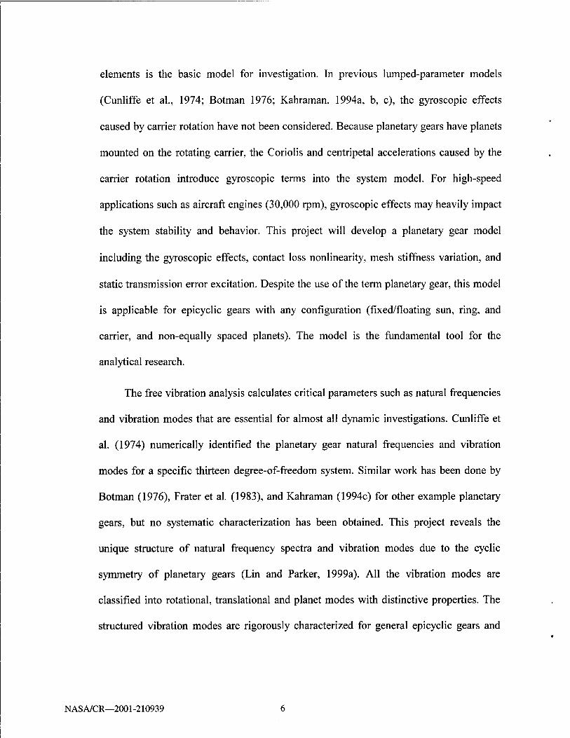
The free vibration analysis calculates critical parameters such as natural frequencies
and vibration modes that are essential for almost all dynamic investigations. Cunliffe et
al. (1974) numerically identified the planetary gear natural frequencies and vibration
modes for a specific thirteen degree-of-freedom system. Similar work has been done by
Botman (1976), Frater et al. (1983), and Kahraman (1994c) for other example planetary
gears, but no systematic characterization has been obtained. This project reveals the
unique structure of natural frequency spectra and vibration modes due to the cyclic
symmetry of planetary gears (Lin and Parker, 1999a). All the vibration modes are
classified into rotational, translational and planet modes with distinctive properties. The
structured vibration modes are rigorously characterized for general epicyclic gears and
NASA/CR—2001-210939

validated by the computational results from a finite element model. These well-defined
properties are not valid when planets are arbitrarily spaced, but still apply to practically
important case of diametrically opposed planets (Lin and Parker, 2000a). The free
vibration properties are very useful for further analyses of planetary gear dynamics,
including eigensensitivity to design parameters, natural frequency veering, planet mesh
phasing, and parametric instabilities from mesh stiffness variations.
Another key issue is how design parameters affect the natural frequencies and
vibration modes. During the design process, model parameters are often altered to
evaluate alternative design choices, reduce weight, and tune the system frequencies to
avoid resonance. The influence of design parameters on planetary gear natural
frequencies was touched on in a few papers, but general conclusions were not presented.
In the plots of natural frequencies versus design parameters, veering phenomena (Leissa,
1974; Perkins and Mote, 1986) often occur and obstruct the tracing of eigenvalue loci
under parameter changes. In the veering neighborhood, where two eigenvalue loci
approach each other and then abruptly veer away, the veering vibration modes are
strongly coupled and change dramatically (Figure 1.3). It is necessary to systematically
study natural frequency and vibration mode sensitivities and their veering characters to
identify the parameters critical to planetary gear vibration. In addition, practical planetary
gears may be mistuned by mesh stiffness variation, manufacturing imperfections and
assembling errors. For some symmetric structures, such as turbine blades, space
antennae, and multi-span beams, small disorders may dramatically change the vibration
NASA/CR—2001-210939

x10
5 - A / r
4.5 - -
^5 X s a 4
s c 3.5 /B -
3 / A -
(a) 10 ks (N/nm)
B
Mode r
Mode s
(b)
Figure 1.3 (a) Two eigenvalue loci veer, (b) The associated vibration modes change dramatically through points A, B, and C. The two modes are strongly coupled at point B.
NAS A/CR—2001 -210939

Figure 1.4 Stability chart of Mathieu equation x + (S - 2e cos 2t)x = 0 (Meirovitch, 1970). The hatched areas are instability regions.
modes and result in mode localization (Pierre, 1988; Cornwell and Bendiksen, 1992;
Happawana et al., 1998). Vibration modes with dominant motion localized in one planet
lead to load sharing unbalance, which can severely undermine the power transfer
efficiency and damage the gear teeth and bearings. This work presents a thorough
eigensensitivity analysis of the natural frequencies and vibration modes to key model
parameters for both tuned (cyclically symmetric) and mistuned planetary gears. The
parameters considered include mesh/support stiffnesses, component masses, moments of
inertia, and operating speed. Taking advantage of the structured vibration mode
NASA/CR—2001-210939

properties, natural frequency sensitivities are expressed in simple, closed-form formulae
which relate the sensitivities to modal strain and kinetic energy (Lin and Parker, 1999b).
Well-defined veering rules are derived from these formulae and vibration mode
properties to predict veering and its strength. The influence of design parameters is
examined through a benchmark example. The knowledge of natural frequency spectra,
vibration mode properties, eigensensitivity formulae, and special veering rules are
combined to provide considerable insight into planetary gear free vibration.
It is well known that mesh stiffness variation is a major excitation source of gear
vibration. For spur gears, the time-varying stiffness is caused by the alternating number
of teeth in contact. It is a periodic function at mesh frequency, which is the number of
tooth mesh cycles per second. The mesh stiffness variation serves as a parametric
excitation and results in instability under certain conditions. Parametric instabilities are
particularly dangerous because they can occur at excitation frequencies well below the
system natural frequencies. The mesh stiffness variation can be further complicated by
the interaction of transmission error excitation (Smith, 1983) and contact loss
nonlinearity (Blankenship and Kahraman, 1995; Kahraman and Blankenship, 1996,
1997). Literature reviews of parametrically excited systems can be found in the work of
Ibrahim and Barr (1978). For a single pair of gears excited by harmonically varying
stiffness, Bollinger and Harker (1967) used the one degree-of-freedom Mathieu equation
to determine the instability regions. The instability conditions are often illustrated in the
plots of the exciting frequency versus the amplitude of varying stiffness, as shown in
Figure 1.4. Benton and Seireg (1978, 1980a) obtained the response to mesh stiffness
NASA/CR—2001-210939 10

variation and external excitations at integer multiples of the rotation speed. They
experimentally verify the resonance region obtained from simulation and demonstrated
the damage of parametric instability on gear teeth. Amabili and Rivola (1997) studied the
steady state response and stability of the single degree of freedom system with time-
varying stiffness and damping. Other researchers (Benton and Seireg, 1981; Kahraman
and Blankenship, 1996; Nataraj and Whitman, 1997; Nataraj and Arakere, 1999) also
investigated gear parametric instabilities using single degree-of-freedom models. For
multi-mesh gear systems, it is surprising to find little investigation on parametric
instability in the published literature. Although Benton and Seireg (1980b, 1981) studied
a gear system with two meshes, they uncoupled the model into two single degree-of-
freedom equations with some simplifications. Their conclusions on the mesh stiffness
phasing effect contradict another investigation (Tordion and Gauvin, 1977) using an
infinite determinant analysis (Bolotin, 1964). This conflict will be clarified using
perturbation analysis (Hsu, 1963, 1965; Nayfeh and Mook, 1979) and numerical
integration methods. In addition, this work extends parametric analysis in two-stage gear
systems to planetary gears where parametric excitations are more complicated as
different contact ratios and phasing conditions exist between the sun-planet and ring-
planet meshes. August and Kasuba (1986) and Velex and Flamand (1996) numerically
computed dynamic responses to mesh stiffness variations for planetary gears with three
sequential phased planets. Their results showed the dramatic impacts of mesh stiffness
variation on dynamic response, tooth loading, and load sharing among planets. The
operating conditions leading to planetary gear parametric instability have not been
NASA/CR—2001-210939 11
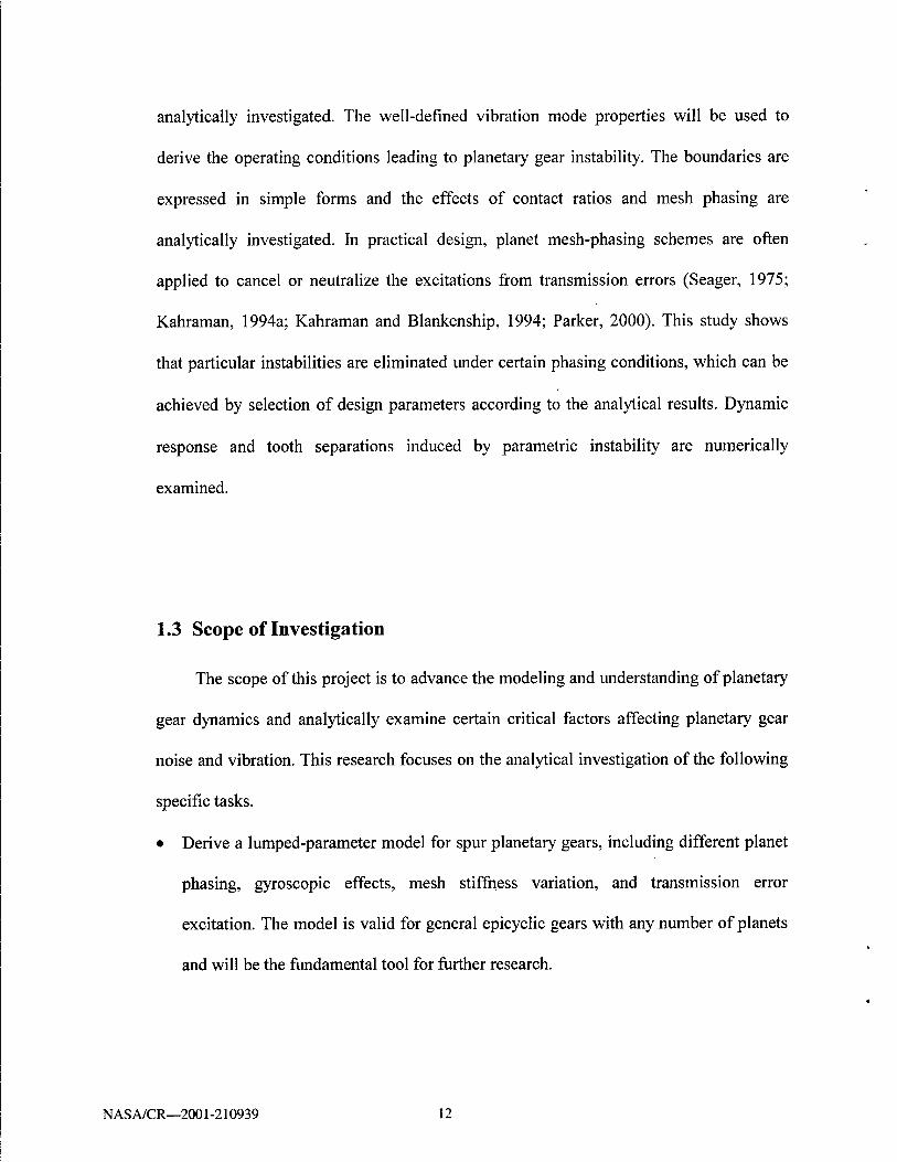
analytically investigated. The well-defined vibration mode properties will be used to
derive the operating conditions leading to planetary gear instability. The boundaries are
expressed in simple forms and the effects of contact ratios and mesh phasing are
analytically investigated. In practical design, planet mesh-phasing schemes are often
applied to cancel or neutralize the excitations from transmission errors (Seager, 1975;
Kahraman, 1994a; Kahraman and Blankenship, 1994; Parker, 2000). This study shows
that particular instabilities are eliminated under certain phasing conditions, which can be
achieved by selection of design parameters according to the analytical results. Dynamic
response and tooth separations induced by parametric instability are numerically
examined.
1.3 Scope of Investigation
The scope of this project is to advance the modeling and understanding of planetary
gear dynamics and analytically examine certain critical factors affecting planetary gear
noise and vibration. This research focuses on the analytical investigation of the following
specific tasks.
• Derive a lumped-parameter model for spur planetary gears, including different planet
phasing, gyroscopic effects, mesh stiffness variation, and transmission error
excitation. The model is valid for general epicyclic gears with any number of planets
and will be the fundamental tool for further research.
NASA/CR—2001-210939 12

Analytically characterize the unique structure of the natural frequency spectra and
vibration modes of general planetary gears. The cases with equally and arbitrarily
spaced planets (including diametrically opposed planets) are considered.
Use the vibration mode properties to obtain simple, closed-form formulae for the
eigensensitivities to important design parameters. According to these formulae and
characterized natural frequency veering rules, the effects of design parameter changes
on planetary gear free vibration are investigated.
Investigate the parametric instabilities caused by multiple time-varying mesh
stiffnesses. Two-stage gear systems are examined first to clarify pervious conflicts and
derive simple expressions of instability boundaries. Then, the analytical method is
extended to planetary gear systems. The well-defined modal properties are used to
identify the effects of contact ratios and mesh phasing on planetary gear parametric
instability.
NASA/CR—2001-210939 13
CHAPTER 2
PLANETARY GEAR MODELING
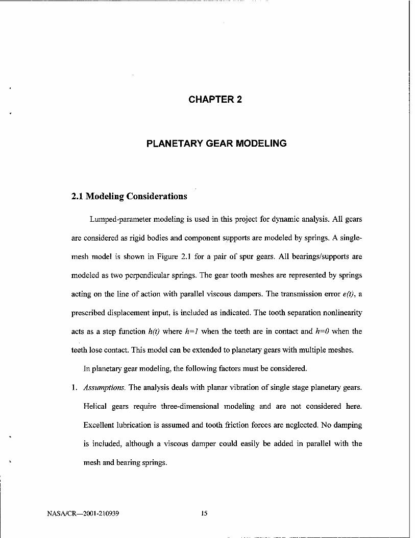
2.1 Modeling Considerations
Lumped-parameter modeling is used in this project for dynamic analysis. All gears
are considered as rigid bodies and component supports are modeled by springs. A single-
mesh model is shown in Figure 2.1 for a pair of spur gears. All bearings/supports are
modeled as two perpendicular springs. The gear tooth meshes are represented by springs
acting on the line of action with parallel viscous dampers. The transmission error e(t), a
prescribed displacement input, is included as indicated. The tooth separation nonlinearity
acts as a step function h(t) where h=l when the teeth are in contact and h=0 when the
teeth lose contact. This model can be extended to planetary gears with multiple meshes.
In planetary gear modeling, the following factors must be considered.
1. Assumptions. The analysis deals with planar vibration of single stage planetary gears.
Helical gears require three-dimensional modeling and are not considered here.
Excellent lubrication is assumed and tooth friction forces are neglected. No damping
is included, although a viscous damper could easily be added in parallel with the
mesh and bearing springs.
NASA/CR—2001-210939 15

c
Mt)
<?e(t)
ö I Mt
Figure 2.1 A single mesh model
2. Versatile configurations. There are many configurations for general epicyclic gears.
By fixing one or more of the coaxial components (carrier, ring, and sun), various
configurations such as planetary, star, and differential gears can be obtained. In
typical designs, one of the coaxial members is free to translate to enhance the load
sharing among planets. The number of planets and their positions also vary in
practical applications. The proposed model should accommodate these configurations
and be flexible for general applications.
3. System coordinates. Several choices of coordinates may be used in the modeling. The
frame can be fixed or rotating; the planet coordinates can be parallel to each other or
use local radial and tangential directions. The coordinate selection does not change
the physical properties of the system, but may greatly affect the analysis difficulty.
NAS A/CR—2001 -210939 16

2.2 System Equations
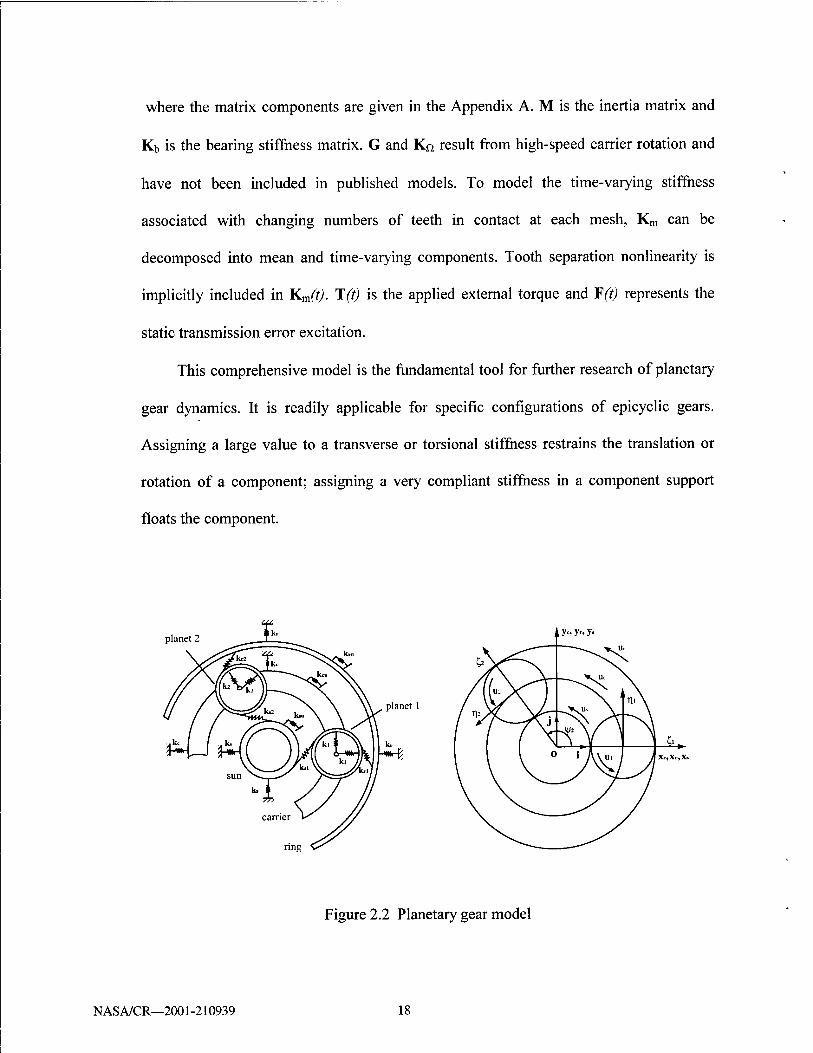
The planetary gear model used in our analysis is shown in Figure 2.2. Each
component has three degrees of freedom: two translations and one rotation. The model is
similar to that used by Kahraman (1994a) with two distinctions: (1) the planet deflections
are described by radial and tangential coordinates, and (2) gyroscopic effects induced by
carrier rotation are modeled. The radial and tangential coordinates more naturally
describe the vibration modes. Gyroscopic effects in high-speed applications such as
aircraft engines may dramatically alter the dynamic behavior from that at lower speeds.
The coordinates illustrated in Figure 2.2 are used. The carrier, ring and sun translations
Xh, yh h=c,r,s and planet translations £n,rjn,n = l,---JVare measured with respect to a
rotating frame of r reference i, j, k fixed to the carrier with origin o. The xn, h=c,r,s are
directed towards the equilibrium position of planet 1, and £,,77n are the radial and
tangential deflections of the «-th planet. The basis i, j, k rotates with the constant carrier
angular speed Qc- The rotational coordinates are uh =rh6h,h = c,r,s,l,---N, where #, is
the component rotation; r/, is the base circle radius for the sun, ring and planet, and the
radius of the circle passing through the planet centers for the carrier. Circumferential
planet locations are specified by the fixed angles y/„, where {//„ is measured relative to the
rotating basis vector i so that y/j = 0. The details of the model derivative are given in Lin
and Parker (1999a). The equations of motion are
,2, Mq + QcGq + [K6+KM-ß^Ko]q = T(0 + F(0 (2.1)
<1= (*c>Jc>Mc'*r^r>Mr'*s'ys'Ms'£l>^l>Ml >'''■>£#'%'"#) carrier ring sun planet 1 planet N
NASA/CR—2001-210939 17
where the matrix components are given in the Appendix A. M is the inertia matrix and
Kb is the bearing stiffness matrix. G and KQ result from high-speed carrier rotation and
have not been included in published models. To model the time-varying stiffness
associated with changing numbers of teeth in contact at each mesh, Km can be
decomposed into mean and time-varying components. Tooth separation nonlinearity is
implicitly included in Km(t). T(t) is the applied external torque and ¥(t) represents the
static transmission error excitation.
This comprehensive model is the fundamental tool for further research of planetary
gear dynamics. It is readily applicable for specific configurations of epicyclic gears.
Assigning a large value to a transverse or torsional stiffness restrains the translation or
rotation of a component; assigning a very compliant stiffness in a component support
floats the component.
planet 2 , i y<» y» y-
planet 1
Figure 2.2 Planetary gear model
NAS A/CR—2001-210939 18

CHAPTER 3
NATURAL FREQUENCY AND VIBRATION MODE PROPERTIES
This chapter analytically investigates the natural frequency spectra and vibration
modes of general planetary gears. The cyclic symmetry of planetary gears leads to
highly-structured free vibration characteristics that are identified herein. Unique
properties of the eigensolutions for the linear time-invariant case are presented for an
example system. The identified properties are then mathematically shown to be
characteristics of general planetary gears.
3.1 Equally Spaced Planets
The free vibration of the linear, time-invariant representation is
Mq + ßcGq + (K-£>c2Kn)q = <) (3.1)
where K=Kb+Km. The carrier speed is assumed to be small and the gyroscopic terms G
and KQ are neglected. The associated eigenvalue problem of (3.1) is
cofMfr = Kfa (3.2)
where co, are natural frequencies and 0. = [pc,pr,ps,pl,---pN]T are vibration modes with
PA =[xh,yh,uhf,h = c,r,s for the carrier, ring and sun, and p„ =[£n,7]n,unf for the
planets. At this stage, the planets are assumed identical and equally spaced; all planet
NASA/CR—2001-210939 19

bearing stiffnesses are equal kp„=kp, all sun-planet mesh stiffnesses are equal (ks„-ksp);
and all ring-planet mesh stiffnesses are equal k^k^. With these specifications, planetary
gears are cyclically symmetric structures that can be divided into N identical sectors. The
cyclic symmetry of planetary gears leads to distinctive natural frequency and vibration
mode properties that will be demonstrated analytically.
We first illustrate the eigensolution properties through a numerical example with
the parameters in Appendix B case I. Typical vibration modes for N=4 are shown in
Figure 3.1, where the movements of the carrier and ring are not shown in order to clarify
the figures. Some interesting conclusions are obtained from Figure 3.1:
1. Six natural frequencies always have multiplicity m=l for different N. Except for the
zero natural frequency, their values increase as additional planets are introduced.
Their associated vibration modes have pure rotation of the carrier, ring and sun
(Figure 3.1a), so these modes are named rotational modes.
2. Six natural frequencies always have multiplicity m=2 for various N. Some natural
frequencies increase monotonically while others decrease monotonically as N
increases. The carrier, ring and sun have pure translation in the corresponding
vibration modes (Figure 3.1b), so these modes are defined as translational modes.
3. Three natural frequencies have multiplicity m=N-3 and exist only if N>3. Their
associated vibration modes are termed planet modes because the carrier, ring and sun
do not move; only planet motion occurs in these modes (Figure 3.1c, d, e). For each
of these three natural frequencies, the corresponding vibration modes span an N-3
dimensional eigenspace.
NASA/CR—2001-210939 20

This example shows there are at most fifteen different natural frequencies for N>3;
additional planets only change the multiplicity of the planet mode natural frequencies.
When N<3, all natural frequencies are distinct and the vibration modes do not have
special structure because of the loss of cyclic symmetry. In nearly all planetary gear
designs, three or more planets are used to take advantage of the load sharing among
planets and subsequent discussion is restricted to this case. The eigensolution properties
identified in the example are analytically shown to be true for general planetary gears
(Lin and Parker, 1999a) and summarized below.
Planet Mode. A planet mode has the form
4=[0,0,0,wlPl,".MvPl]r (3.3)
where w„ are scalars (wj=l) satisfying
IX sin ^„=0 I>„cos^H=0 Ew»=° (3-4)
Planet modes have the following characteristics:
(i) The associated natural frequency has multiplicity N-3,
(ii) The translation and rotation of the carrier, ring and sun are zero,
(iii) The planet deflections are scalar multiples of the first (or any other arbitrary)
planet's deflection components.
Rotational Mode. A rotational mode has the form
<Pi = [Pc>Pr>P*>Pl> >Plf (3-5)
Rotational modes have the following characteristics:
(i) The associated natural frequency is distinct,
NASA/CR—2001-210939 21

(ii) The translation of the carrier, ring and sun are zero, i.e., ph - [0,0,«;,]r, where j=c,r,s,
(iii) All planets have identical deflections, i.e., p, =p2 =--=p^ = [^TI,/71,M1]7
' .
Translational Mode. A pair of translational modes has the form
0,
Pc
p,
p. (cos^pj + sin ^jPi)
(cosy^+sin^p!)
<P,=
Pc
p,
(-sin^P! 4-cos^p,)
(-sin^p.+cos^p,)
(3.6)
Translational modes have the following characteristics:
(i) The associated natural frequency has multiplicity two.
(ii) The rotation of the carrier, ring and sun are zero. Furthermore, the carrier, ring, and
sun translations in the degenerate modes $ and ^ are related by p,, =[x,,,7;,,0]rand
Ph=i-yh^h,0]T,h=c,r,s,
(iii) The planet deflections for a pair of vibration modes are related by
P„
P«
cos^„I sin^„I
-sin^„I cos^„I Pi
Pi (3.7)
where pn and p„ =[£„,T]IJ,un]T are the deflections of the w-th planet in $ and <f>{. I is
a 3x3 identity matrix and y/n = 2n{n -1) / N,
NASA/CR—2001-210939 22

(a) rotational mode (b) translational mode
(c) radial planet mode (d) tangential planet mode
(e) rotational planet mode
Figure 3.1 Typical vibration modes. Dashed lines are the equilibrium positions and solid lines are the deflected positions. Dots represent the component centers.
NASA/CR—2001-210939 23

3.2 Arbitrarily Spaced Planets
In general, much of the above well-defined structure of the natural frequency
spectra and vibration modes is lost when the planets are arbitrarily spaced. A notable
exception is the planet modes. Additionally, for the practically important case of
diametrically opposed planets, the free vibration retains its unique properties.
Planet Mode: As for planetary gears with equally spaced planets, systems with
arbitrary planet spacing always have three sets of planet modes of the form (3.3) with
multiplicity N-3. Only the coefficients w„ obtained from (3.4) are affected by y/„.
Rotational Mode: In general, the rotational and translational modes couple together
for arbitrary planet spacing and no special modal structure can be identified. For certain
planet spacing, however, they still have distinguishing properties. A case of particular
interest is that of diametrically opposed planets, which is common in industrial
applications. Consider a system with each ofN/2 pairs of planets located along arbitrarily
oriented diameters. A pair of opposing planets have the position relation %+N/2=W"+m m
this case,
£wHsin^„=0 Xw„cos^,=0 Zw»=° (3-8)
Accordingly, systems satisfying (3.8) have six rotational modes with property (3.5). For
arbitrarily distributed planets not satisfying (3.8), rotational modes do not exist.
Translational Mode: While the translational modes couple with the rotational
modes for truly arbitrary planet spacing, they retain their structure for systems satisfying
(3.8). The notable difference with equally spaced planet systems is that the natural
frequencies are no longer degenerate because the cyclic symmetry is disturbed. To start
NASA/CR—2001-210939 24
with, the planet deflection relations in a translational mode are derived from (3.7) for any
three planets i,j, k,
sin(Vi - Wj)Pk + sin(f/ - ¥k)P< + sin(^ - yft)p; = 0 (3.9)
Thus, the n-th planet deflection can be expressed as a linear combination of pi and p2.
The component modal deflections for a translational mode become
Ph=ixh,yh,uh], h = c,r,s, p„=[sin(^2-^JPl+sin^„p2]/sin^2 (3.10)
Therefore, planetary gears with planet positions satisfying (3.8) (for example,
diametrically opposed planets) have twelve distinct vibration modes that have the special
structure (3.10) of a translational mode.
3.3 Modal Strain and Kinetic Energy
The vibration modes can be further characterized by modal strain and kinetic
energy. The total modal strain energy U and kinetic energy T are related to the natural
frequencies and vibration modes by
U = ±tfK0, = Uc+Ucu+Ur+Uni+Us+Usu+f4(Un+Um +UJ (3.11) z »=i
T = ±a>?tfm=Te+T„+Tr + T„+T, + Tm+%(Tn+Tm) (3.12) L H=l
where (i) Uh, Uhu, h= c,r,s are the strain energies in the translational and rotational
support springs, respectively, of the carrier, ring and sun; (ii) U„, Um, Us„, n=l, ..., N are
the strain energies in the n-th planet bearing, ring-planet mesh and sun-planet mesh; and
NASA/CR—2001-210939 25
(iii) Th, Thu, h=c, r, s and T„, T„u are the modal translational and rotational kinetic
energies, respectively, of the carrier, ring, sun, and planets. The detail of these individual
energies are
Vh = - K (xf, + y\), Ulm = - khll u2
h, h = c, r, s
Til I Th=-f(of(xl+yl), Th=-£atul h = c,r,s (3.13)
m I T„=-fco2{£ + if,), Tmi=-^0)2ul
1 lrp
where the mesh and bearing deflections S are defined below.
sun-planet mesh: Sm =y,ca&yrm-xs&nyfm-£„w\as-Ti„Ga&a, + u,+u„+em (3.14)
ring-planet mesh: Sn, = yr cos y/m - xr sin ym - C„ sin a,. + ij„ cos ar + ur - u„ +e„, (3.15)
planet bearing radial: 8m = yc sin i//n + xc cosy/n - £"„ (3.16)
planet bearing tangential: Sm = yc cosy/n - xc sin y/„ - V„ + uc (3.17)
For the example planetary gear (Appendix B, case II), the modal strain and kinetic energy
distributions are shown in Figure 3.2, and the dominant motion and strain energy are
listed in Table 3.1. According to (3.13), the dominant kinetic energy occurs in the
component with dominant motion. Modal strain energy indicates those vibration modes
most susceptible to parameter variation and identifies the most heavily loaded component
for response. In the next chapter, the modal energy distribution will be used in the
derivation of simple formulae to calculate eigensensitivity to key design parameters.
NASA/CR—2001-210939 26
3.4 Discussions
Planet modes of multiplicity N-3 are remarkably insensitive to planet location and
retain their special properties for arbitrary planet spacing. Coupling between rotational
and translational modes occurs for arbitrary planet spacing, and distinct properties can
not be identified. For systems satisfying (3.8), however, rotational and translational
modes have structured properties. This includes the common case of equally spaced and
diametrically opposed planet pairs. The foregoing development applies to general
epicyclic gear configurations. Configurations having fixed or floating components are
obtained by letting the associated bearing stiffness approach zero or infinity to obtain the
eigensolution properties. For example, for the cases of a fixed ring, fixed sun or fixed
carrier, a 3(N+2) degree of freedom system is obtained. The vibration modes in such
systems consist of five rotational, five pairs of translational and three groups of planet
modes.
The free vibration properties have been validated through a finite element
computation. A finite element model (Figure 3.3) for this system was built by Agashe
(1998) and Parker, et al. (2000) and analyzed with CALYX (Vijayakar, 1991).
Computational modal analyses were performed by applying impulse inputs and obtaining
the frequency response functions. The identified natural frequencies match the analytical
results (Table 3.2) within 3.3 percent difference.
NASA/CR—2001-210939 27

mode 2,3
■■-■11 2 4 6 8 10 12 14
mode 6,7
Jrfll 2 4 6 8 10 12 14
mode 11 1 2 4 6 8 10 12 14
2 4 6 8 10 12 14 2 4 6 8 10 12 14 2 4 6 8 10 12 14
(a) Normalized modal strain energy at the sun/planet meshes (1-4), ring/planet meshes (5-8), planet bearings (9-12), carrier and sun bearings (13, 14).
2 4 6 8 10 12
mode 15
L-JfflJ :LL
2 4 6 8 10 12
mode 9,10
lliLL 2 4 6 8 10 12
mode 14
2 4 6 8 10 12 JLUL
2 4 6 8 10 12
mode 16,17 mode 18
2 4 6 8 10 12 2 4 6 8 10 12 2 4 6 8 10 12
(b) Normalized modal kinetic energy at the carrier, sun, planet translations (1,2,3-6), and carrier, sun, planet rotations (7,8,9-12).
Figure 3.2 Modal energy distributions of the system in Appendix B, case II.
NAS A/CR—2001-210939 28

No. /(Hz) Type Dominant motion Dominant strain energy
1 0 R Rigid body mode
2,3 825 T All components Carrier, sun bearings
4 1661 R All components Planet bearings
5 1808 P Planet radial translation Planet bearings
6,7 1834 T Sun, planet translation Sun, planet bearings
8 1985 R Sun rotation, planet translation Planet bearings
9,10 2326 T Sun, planet translation Sun, planet bearings
11 5964 P Planet tangential translation All meshes
12,13 6429 T Planets Ring-planet meshes
14 6451 R Planets Ring-planet meshes
15 6982 P Planet rotation All meshes
16,17 10430 T Sun translation Sun-planet meshes
18 13068 R Sun rotation Sun-planet meshes
Table 3.1 Dominant motion and modal strain energy in the vibration modes of the system in Appendix B. R: rotational mode, T: translational mode, P: planet mode.
Mode Type Trans Rot Plan Trans Rot Trans
FEM (Hz) 778 1144 1729 1676 1723 2110
Analytical (Hz) 769 1156 1609 1710 1781 2175
Difference (%) 1.2 -1.0 2.3 -2.0 -3.3 -3.0
Table 3.2 Comparison of analytical and FEM natural frequency analyses.
NAS A/CR—2001 -210939 29

Figure 3.3 Finite element model of the planetary gear
The well-defined eigensolution properties are useful for subsequent research
because almost all analytical investigation of planetary gear vibration phenomena
ultimately require the natural frequencies and vibration modes. This includes, for
example, critical dynamic behaviors such as forced response to static transmission error,
use of planet phasing to eliminate excitation of particular modes, parametric instability
from time-varying mesh stiffness, contact loss nonlinearities, natural frequency and
vibration mode sensitivity to key design parameters and gyroscopic effects. The specific
properties characterized in this paper theoretically explain the selective participation of
NASA/CR—2001-210939 30

the different classes of vibration modes in planetary gear dynamic response (Parker et al.,
2000a; Parker, 2000). Additionally, the structured vibration mode properties lead to
simple, exact formulae to calculate natural frequency and vibration mode sensitivity to
parameter changes (Lin and Parker, 1999b). Using these properties, well-defined veering
rules of natural frequency loci are analytically derived (Lin and Parker, 2000b). These
special veering rules help to trace the evolution of the loci for changes in the design
parameters and identify the veering zones where vibration modes undergo dramatic
changes. Apart from analytical applications, the identified natural frequency structure
provides important information for tuning the system frequencies to avoid resonance.
There are at most 15 different natural frequencies in general planetary gears with N
planets, so there are only 15 potential resonant frequencies.
NASA/CR—2001-210939 31
CHAPTER 4
EIGENSENSITIVITY TO DESIGN PARAMETERS
During the design process, system parameters are varied to evaluate alternative
design choices, avoid resonances, optimize load distribution, and reduce weight. It is
important to characterize the effects of parameter variations on the natural frequencies
and vibration modes for effective vibration tuning. In planetary gear dynamic models
(Figure 2.2), the key design parameters include the mesh stiffnesses, support/bearing
stiffnesses, component masses, and moments of inertia. The influence of some design
parameters on planetary gear natural frequencies was touched on in a few papers. Botman
(1976) and Cunliffe et al. (1974) both presented plots of natural frequencies versus planet
bearing stiffness. Kahraman (1994c) showed the effects of mesh/bearing stiffnesses on
the natural frequencies in his torsional model of planetary gears. Saada and Velex (1995)
discussed the influence of ring support stiffness on free vibration. These analyses were
based on parametric studies of example planetary gears and assume the planetary gears to
be cyclically symmetric (tuned) systems. Eigensensitivity analysis for mistimed systems
is necessary to identify the critical modes that are susceptible to irregularity. Frater et al.
(1983) studied the vibration modes with one unbalanced mesh stiffness, but general
NASA/CR—2001-210939 33

conclusions were not obtained. This project analytically investigates the natural
frequency and vibration mode sensitivity to most system parameters such as
mesh/bearing stiffnesses, component masses and moments of inertia. Simple, closed-form
expressions are obtained to calculate eigensensitivities for both tuned and mistuned
system. In addition, eigenvalue veering phenomena are investigated to identify dramatic
changes of natural frequencies and strong coupling of vibration modes. Design guidelines
are summarized from eigensensitivity and veering analyses to predict influences of
system parameters on planetary gear free vibration.
4.1 Calculation of Eigensensitivity
The eigensensitivity analysis calculates natural frequency and vibration mode
derivatives with respect to stiffnesses, masses, moments of inertia and the carrier rotation
speed Qc. Eigensensitivity to stiffness and inertia design parameters are examined in the
absence of gyroscopic effects Qc. Gyroscopic effects are important in high-speed
applications such as aircraft engines, and eigensensitivity with respect to Qc is studied
separately in section 4.4. The eigenvalue problem for the study is in form (3.2), i.e.,
(K-W,=0 (4.1)
where Ä,=o^2. The eigensensitivity for problems in the form (4.1) has been thoroughly
investigated (Courant and Hubert, 1953; Adelman and Haftka, 1986; Friswell, 1996) and
the necessary results are introduced below. The unique modal properties of planetary
NASA/CR—2001-210939 34

gears are then invoked to reduce these general results to simple expressions specific to
planetary gears.
Let ( )' and ( )" denote the first and second derivatives with respect to a model
parameter (i.e. mesh/bearing stiffness, component mass or moment of inertia). For
simplicity, the eigenvalue derivatives X{ and V' are calculated; the relations cOj'^Aj'/ßcoi)
and coi/>'=(2AiAi"-Aj£)/(4coi3) yield the natural frequency sensitivities. For a distinct
eigenvalue, the eigensensitivities are (Fox and Kapoor, 1968; Rogers, 1970)
4'=#(K'-4M')$ (4.2)
<P/= --(^M '0M + X ^— ^% (4.3)
A;'= 2tf (K ' - A,M ')*, + </>■ (K " - X,M " - 2 Afil ')f (4.4)
For the case of degenerate eigenvalues, consider a system having a group of
eigenvalues A]=...=Äm with multiplicity m. The first-order eigenvalue derivatives /I/are
the eigenvalues of
Da, =4a„ D = rT(K'-A,M,)r (4.5)
where T=[yi,...,ym] is an arbitrary set of independent eigenvectors associated with this
degenerate eigenvalue and is normalized such that T MT = Imxm. For the case when all
A,-'obtained from (4.5) are distinct, the a; are uniquely obtained with the normalization
aiTai =1. This procedure determines the set of independent eigenvectors <^—Tüi that admit
continuous change of the eigenvectors as the degenerate eigenvalues split into distinct
ones when a parameter is varied.
The eigenvector derivatives for distinct V are expressed as (Friswell, 1996)
NASA/CR—2001-210939 35

# = v,. +Oc,, I = 1,---,W (4.6)
where
v, = t tf(1f-K,)%, (4.7)
2^(K'-A,M/)V,+^(K'-A,M'-2^;M
/M
S = — ^7 > 7 * * (4.8) A,.-A,
c. =-I<DrM/0> (4.9)
The second derivatives are
4"=20,r(K'-;i,.M>,. +^(K'-/1,M'-2A;M>,, i=\,-,m (4.10)
For the case when all A>■'obtained from (4.5) are degenerate, the a, are not unique
and hence $, i-1,..., m are arbitrary in the eigenspace. The eigenvector derivatives can
not be determined when these degenerate modes do not separate. However, /I/'can be
obtained from the eigenvalues of (Friswell, 1996)
E = 2<Dr(K'-A,M')V + 07'(K'-A,M'-2A;M,)^> (4.11)
where V=[vi,...,vm] is determined by (4.7). A,-"are not affected by the selection of O.
The foregoing development is used subsequently to derive general, closed-form
eigensensitivity relations for A,' 0'and A,"for planetary gears. These expressions yield
eigensolution approximations according to
Ä = Ä + 2^^-\p = P0(P-Pol </> = ^> + L^-\p = Po(p-Po) (4-12) P dp p dp
where p represents any system parameter with nominal value />o and multiple parameter
perturbations are permitted. Eigensolutions A, <p are for a nominal set of model
NASA/CR—2001-210939 36

parameters referred to as the unperturbed system, and the derivatives are evaluated for
this unperturbed system. Eigensolutions A, (f> are for the perturbed system with varied
parameters. The unperturbed system is taken to be tuned in this study. Note that this does
not meaningfully restrict the results because parameter variations leading to both tuned
and mistimed perturbed systems are examined.
4.2 Eigensensitivity to Mesh and Support Stiffnesses
The stiffnesses under consideration (Figure 2.2) include mesh stiffnesses km, ks„,
transverse support stiffnesses kc, kr, ks, k„, and rotational support stiffnesses kcu, kru, ksu.
The natural frequency sensitivity to a certain stiffness is found to be uniquely associated
with the modal strain energy occurring in that spring. To demonstrate the procedure, let
the sun-planet mesh stiffness ksn be the varied parameter.
4.2.1 Tuned System
Considered the case where all sun-planet mesh stiffnesses ks„=ksp are altered
equally so the perturbed system remains tuned. For rotational modes, the
eigensensitivities are obtained from (4.2)-(4.4)
f-ico1 (4.i3) OKsp «=1
-SJT=E Z-fIrÄ (4-14)
NASA/CR—2001-210939 37

^^iT^T-d^Ä)2 (4-15) dk;p k=x A, - Ak „=1
where 8\n is the spring deformation of the sun-planet n mesh in mode fa given (3.14).
The rotational mode property (3.5) dictates that all sun-planet mesh deformations are
equal, i.e., 8'm = 8'sX, so (4.13) becomes
dÄ> =N(S'sl)2 (4.16) K
In (4.14), $'is expressed as a modal expansion of eigenvectors, and the contribution of
each eigenvector is readily obtained from the coefficients of fa. When two eigenvalues At
and /Uare nearly equal, the influence of fa on $'is dominant because the denominator in
its coefficient is small. In such cases, the second derivative ^''is also large, and the
natural frequency changes rapidly with ksp.
The translational mode eigenvalues A12 do not separate because the perturbed
system remains tuned. Thus, the matrix D in (4.5) has degenerate eigenvalues A,/, Ao'.
Accordingly, the unperturbed eigenvectors fa 2 can not be uniquely determined from the
procedure associated with (4.5), and ^=[fa,fa] are an arbitrary pair of translational modes
of the unperturbed system. From (4.5), X\, \-i are the eigenvalues of
D = OrK'0 = ]T n=\
(4.17)
NASA/CR—2001-210939 38

Use of the translational mode property (3.6) yields ^ _X<>1„)2 =X ,ißl,)2»
X - 4L 4» =^- Thus, the eigenvalues of D {i.e., A/, A2) are degenerate and have the
form (4.13) for i=l,2. From (4.11) and the translational mode properties, A]", A2 " are
^sp k=3 »=1 Aj \
Planet modes are also degenerate and the procedure is similar to that for
translational modes. For planet modes O=[0/, ...,$2], the elements of the matrix D are
Dtj =^ 4» 4^ f°r ij=l,—,m. Applying planet mode property (3.3) to calculate 4«
results in Du=...= Dmm and Df= 0, i^j. It follows that all V of a group of planet modes
are equal and can also be expressed as (4.13) for ij=l,...,m. In the same way, all A/'
ij=1, ...,m are equal and of the form (4.18).
Equation (4.13), which is valid for all three types of vibration modes, can be related
to the modal strain energy U in ()),. With the definition of strain energy Us„ in (3.13),
(4.13) becomes
dA 2 Ä d(Ol 1 ^ = T-IX, !T- = -^rLum (4.19)
Equation (4.19) allows one to obtain the natural frequency sensitivity to sun-planet mesh
stiffness by inspection of the modal strain energy distribution.
As an example, consider a planetary gear used in the transmission of a U.S. Army
OH-58 helicopter. The nominal model parameters are listed in Appendix B, case II. The
natural frequencies from (4.1) are shown in Figure 4.1a for a range ksp. The strain
NASA/CR—2001-210939 39

energies of each spring are calculated according to (3.11) and their distribution in mode
16 (a translational mode) is shown in Figure 4.1b,c for two cases: ksp=70 Nl\im and
ksp-500 N/[im. The associated vibration mode (pit is also shown for these two cases.
Little strain energy is stored in the sun-planet meshes Us„ for case I, while substantial
strain energy results in case II. Consequently, coic is more sensitive to ksp in case II than
in case I. This conclusion is consistent with the larger slope of the ü)j6 locus for case II in
Figure 4.1a. In fact, natural frequency sensitivities to all stiffnesses can be obtained
quantitatively directly from the strain energy distribution using (4.19) and analogous
relations (4.20) and (4.21) below.
fr4+yl=iu" it-H"- h-c'r-s (4-20)
#-=i<o,+<*)j-fit'.. Ih£c«.>2-f£i/- (4-2i)
These relations apply for all three types of vibration modes. Expressions for $'and A/'
for all of the stiffness parameters are collected in Lin and Parker (1999b). Recalling the
special properties of vibration modes, (4.19)-(4.21) imply that
1. Rotational modes are independent of the transverse support stiffnesses of the carrier,
ring, and sun because these components have no deformation of, and hence no modal
strain energy in, their transverse support springs. Thus, use of a "floating" sun, ring,
or carrier i.e., low stiffness support) has no impact on rotational modes.
2. Translational modes are similarly independent of the rotational support stiffnesses of
the carrier, ring, and sun.
3. Planet modes are insensitive to all carrier, ring, and sun support stiffnesses.
NASA/CR—2001-210939 40

4 x10 (a)
/ I
i
/
6 I -
5
I I I I II
18^^ ^^16,17 15/^ -
4 ST
T
I I
14^
f3 "^L2J3 n^-^" -
2 I -
l
1 I ' I
~
I i . , i . . ,
10' ksp (N/n m) 10°
(b) case I (c) case II
E>3 a> c
c 'ra
n r 1 ■*—' I I
Un Uc Us
Figure 4.1 (a) natural frequency versus the sun-planet mesh stiffness ksp. (b), (c) Mode 16 strain energy distribution in case I and case II. All U are defined in (3.11).
NASA/CR—2001-210939 41

4.2.2 Mistuned System
In practical planetary gears, mistuning may be caused by differing mesh stiffnesses
between planets due to differing numbers of teeth in contact, manufacturing variations,
and assembly errors. To study the effects of mistuning on eigensolutions, we examine the
sensitivity to parameter variations that differ between the planets. Consider an example
with only the first sun-planet mesh stiffness ksj varying from the nominal (unperturbed)
value ksp. The derivatives of the mass and stiffness matrices with respect to ksi are
M'=M"=K"=0, K' = OUJksl.
The eigensensitivities of the rotational modes are obtained from (4.2)-(4.4)
■§- = &? =-TUA (4.22)
£=%?$* (4-23)
^ty^OM)2 (4-24) k*i
Equation (4.22) relates Xi/ to the modal strain energy in the first sun-planet mesh.
Equations (4.22)-(4.24) are similar to (4.13)-(4.15) without the summation over n
because the varying parameter is located only at the first sun-planet mesh.
For translational modes, the eigensensitivities are (Lin and Parker, 1999b)
f-^f, f-ri&=0 (4.25)
^,i k^\-\ oksl
*,2. an1 stir
NASA/CR—2001-210939 42

The behavior of fa and fa is shown in Figure 4.2 for the example of Appendix B, case EL
A pair of translational mode natural frequencies separate as a disorder £=ks]/ksp-l is
introduced. The modal strain energy distributions in the four sun-planet meshes are
shown for £ = 0, -0.1. fa is sensitive to ksi because of the high strain energy in the first
sun-planet mesh, fa has no strain energy in the first sun-planet mesh and is independent
of ksj. The linear (^ + £kspA£ ) and quadratic (^ + £k A£ + £2kspA£') approximations of
the loci are shown in Figure 4.2 and agree well with the exact loci. These two loci
intersect exactly at e - 0 when there is only one disorder in the perturbed system. If one
more disorder £2=kS2/ksp-l = 0.1 is added at the second mesh (Figure 4.3), the two loci
suddenly change direction and veer away. For an initially tuned (cyclically symmetric)
system, two independent varying parameters {e.g., ksi and ksi) are necessary to break the
symmetry of both fa and fa and cause frequency loci veering (Happawana et al, 1998).
The regular perturbation does not give a good approximation in the veering zone where
two loci are close to each other. Singular or improved perturbation methods are needed
(Pierre and Murthy, 1992; Wu, 1993; Chen et al., 1995; Lin and Lim, 1997). If the
number of planets N= 4 or 5, the planet modes have multiplicity m=l,2 and their
eigensensitivities are obtained from (4.22)-(4.24) or (4.25)-(4.27). When N>5,
eigensolutions of matrix D in (4.5) are difficult to achieve in closed-form, but can be
obtained numerically.
NASA/CR—2001-210939 43

Figure 4.2 Influence of the disorder e on the natural frequencies. Linear (...) and quadratic (—) approximations agree well with the exact loci (—).
TO 6.6
Usn
nil /^
/ -*
im : ■ i
0.2 0.15 0.1 0.05 0 0.05 0.1 0.15 0.2 0.25 0.3
e = ksi/ksp -1
Figure 4.3 Influence of two disorders on the natural frequencies. Another disorder £2=kS2/ksp-l-0.1 at the second mesh is added to the system shown in Figure 4.2.
N AS A/CR—2001-210939 44

4.3 Eigensensitivity to Gear Mass and Inertia
The parameters of interest consist of masses (mc, mr, ms, mp) and moments of inertia
{Ic,Ir, Is, Ip) for the carrier, ring, sun, and planets. When the perturbed system remains
tuned, the eigenvalue derivatives for the three types of modes are
^- = -Mx2h+yl) = -^-Th, ^- = -A1u
2h=-yTl1u, h = c,r,s (4.28)
dmh mh dmhu Ih
<?4 N 9 N 31 2 N 0 N
= -4E(£ + tf) = --^5X ^ = -^YA=-fIjnu (4.29) «=1 mp n=\ 01 p 'p n=l *p n=\
where 7/,, ThU, h=c, r, s and T„, T„u are the modal kinetic energies defined in (3.12).
Expressions for (j>( and A/' for all of the mass and inertia parameters are collected in Lin
and Parker (1999b). Figure 4.4a shows an example plot of the natural frequencies versus
the sun moment of inertia Is. Most natural frequencies are insensitive to changes in Is. The
kinetic energy distribution and vibration modes of mode 18 (a rotational mode) are
shown in Figure 4.4b,c for cases I and II. The sun has more rotational kinetic energy Tsu
in case I than in case II, so CDis locus has larger slope in case I. Equations (4.28) and
(4.29) allow quantitative calculation of natural frequency sensitivity to all masses and
moments of inertia directly from the modal kinetic energy distributions. Considering the
properties of vibration modes, some conclusions are immediate from (4.28) and (4.29):
1. Rotational modes are independent of the masses of the carrier, ring, and sun because
such modes have no translations of these components.
2. Translational modes are similarly independent of the moments of inertia of the
carrier, ring, and sun.
3. Planet modes are independent of both masses and inertias of the carrier, ring, and sun.
NASA/CR—2001-210939 45

10 X 104 (a)
I \ I I > i i 1
9 -
8 \. (018
-
7 -
6
■a _ 2 5
n
" ~
4
3 -
2 -
1
i ■ ■Fit , ,
a) 4 0) u | 2
0
0.2 0.4 0.6 0.8 1 1.2
i/rf(kg) 1.4
(b) case I
1.6 1.8
(c) case I
Tn Tnu
Tc Ts TCU TSL Tcu TSL
Figure 4.4 (a) Natural frequency versus the sun moment of inertia Is. (b), (c) Mode 18 kinetic energy distribution in case I and II. The Tare defined in (3.12).
NASA/CR—2001-210939 46

4.4 Eigensensitivity to Operating Speed
In high-speed applications (e.g. aircraft engines), gyroscopic effects may
significantly alter the system stability and dynamic behavior. Eigenvalue derivatives
evaluated for £2C=0 are calculated to assess the influence of operating speed on the
natural frequency spectrum. The gyroscopic eigenvalue problem of (3.1) is obtained from
the separable solution q = (j>ieJm''
K2M + MßcG + (K-fic2Kfll=0 . (4.30)
For practical operating speeds !2C=0 (i.e., subcritical), the eigenvalues remain purely
imaginary. Suppose a zero speed natural frequency (Oj has multiplicity m and the
arbitrarily chosen independent eigenvectors are r=[yi,...,ym] with normalization
rrMr = imxm. While eigenvectors for QjtQ are complex, the y are real. Differentiation of
(4.30) with respect to Qc and evaluation at £2C=0 yield
(K - ai}M)ft = (2o)to)^L - jco^Ta, = f (4.31)
where 0, = Ta,. Applying solvability and normalization conditions results in an mxtn
Hermitian eigenvalue problem
Da; = afa, D = yrrGr / 2 (4.32)
The natural frequency sensitivities m' are obtained from the eigenvalues of (4.32) for the
three classes of vibration modes. Rotational mode natural frequencies are distinct and
(4.32) becomes a scalar equation. Hence co'= 0 because yfGyt = 0 for real yi and skew-
symmetric G. For translational modes yi and y^, D and its eigenvalues are
NASA/CR—2001-210939 47

1.6 x10 1
10 .
1.4 - 9
8
-
1.2 6,7 -
5
üT
1 1 4 - S
0.8 -
0.6 3 -
2 i i i i i
100 200 300 il (rad/s)
400 500 600
Figure 4.5 Natural frequency versus the carrier rotation speed
D = rlG72
rlGy2 o co[2=±yT
xGy2l2 (4.33)
For a group of planet modes yi,...,ym, the properties (3.3) guarantee Dtj = y1iGyj = 0 for
i?$. Dj,=0, i=l,..., m because of the skew-symmetry of G. Thus, D=0 and all planet
mode natural frequency sensitivities vanish, i.e., co'= 0.
Equation (4.33) can be used to approximate the frequency loci C0t = 0)i +QC0)'.
The result (o[= 0 for rotational and planet modes at Qc = 0 indicates the natural
frequencies of these modes are scarcely affected by operating speed. Figure 4.5 shows the
NASA/CR—2001-210939 48

first 10 frequency loci versus Qc for the gear system in Appendix B case II. The
rotational mode {0)4, (Os) and planet mode {(O5) loci are nearly flat lines and not sensitive
to operating speed. Translational mode frequencies {0)2,3, (Qsj, (09,10) split as Qc is
increased from zero. In this example, 0)2 and CO3 at £2C=600 rad/s deviate about 10 percent
from the zero speed value. Typical helicopter carrier speeds are less than 100 rad/s. For
applications with high speed {e.g. turbofan and turboprop engine systems), heavy
component masses, and compliant stiffnesses, the gyroscopic effects can be more
significant. If a natural frequency locus has large slope and decreases to zero in the range
of operating speed, the stability and system behavior are dramatically impacted.
4.5 Natural Frequency Veering
In the plots of natural frequencies versus design parameters, eigenvalue veering
occurs, where two eigenvalue loci approach each other as a parameter is varied but then
abruptly veer away like two similar charges repelling (point B in Figure 4.6a). The
phenomenon has been studied extensively (Leissa, 1974; Perkins and Mote, 1986; Pierre,
1988; Chen and Ginsberg, 1992). The vibration modes of the veering eigenvalues are
strongly coupled and undergo dramatic changes in the veering neighborhood. In the case
of especially sharp veering, it is sometimes difficult to distinguish between intersection
and veering just by observing eigenvalue plots. When multiple curves veer or intersect
close together (Figure 4.6a), strong modal coupling, and the associated operating
condition response changes that occur, are not identifiable from frequency loci plots. The
NASA/CR—2001-210939 49
objective of this work is to analytically characterize the rules of eigenvalue veering in
planetary gear vibration. Simple rules emerge to predict if two eigenvalues veer or cross.
The veering sharpness is also calculated.
4.5.1 Veering/Crossing Criterion
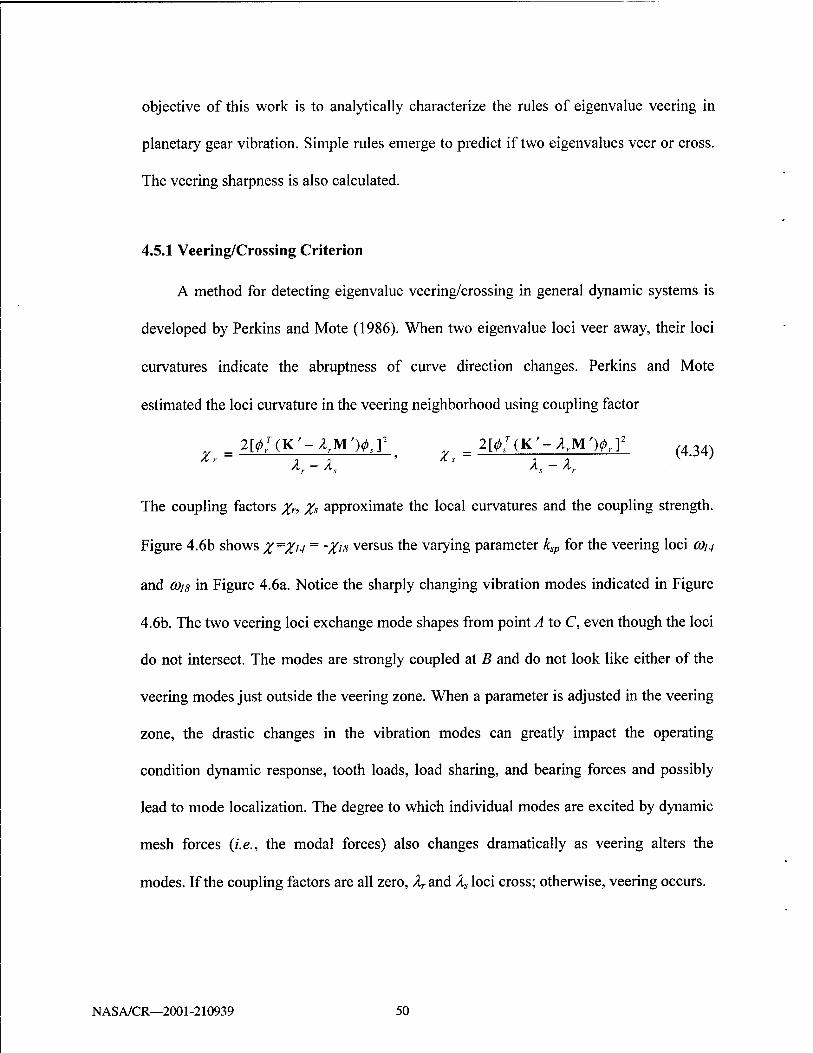
A method for detecting eigenvalue veering/crossing in general dynamic systems is
developed by Perkins and Mote (1986). When two eigenvalue loci veer away, their loci
curvatures indicate the abruptness of curve direction changes. Perkins and Mote
estimated the loci curvature in the veering neighborhood using coupling factor
_ 2[^(K'-/lrM>J2 __ 2[^(K'-ArM')<p,.]2 (434) Xr K-K ' Xs K-K
The coupling factors Xr, X* approximate the local curvatures and the coupling strength.
Figure 4.6b shows X~Xu = 'Xis versus the varying parameter ksp for the veering loci (Ou
and 0)i8 in Figure 4.6a. Notice the sharply changing vibration modes indicated in Figure
4.6b. The two veering loci exchange mode shapes from point A to C, even though the loci
do not intersect. The modes are strongly coupled at B and do not look like either of the
veering modes just outside the veering zone. When a parameter is adjusted in the veering
zone, the drastic changes in the vibration modes can greatly impact the operating
condition dynamic response, tooth loads, load sharing, and bearing forces and possibly
lead to mode localization. The degree to which individual modes are excited by dynamic
mesh forces {i.e., the modal forces) also changes dramatically as veering alters the
modes. If the coupling factors are all zero, /^and A5loci cross; otherwise, veering occurs.
NASA/CR—2001-210939 50

x10
cc 4
(a)
- 18R /
/ 16,17T>/
/
-
E3/
15P/
14IJ^ -""12^31 11P/-- nominal
- 9.10T
-
8R 0.7T 18R
2,3T
5P 1
10 ksp(N/nm) 10
Figure 4.6 (a) Natural frequencies versus the sun-planet mesh stiffness. Natural frequencies are numbered under the nominal conditions (dashed line) in Table C.l. Three pairs of veering are loci 14 and 18, (12,13) and (16,17), and 11 and 15. (b) Coupling factor x of 0)14 and cois. These two loci exchange mode shapes from point A to C.
NASA/CR—2001-210939 51
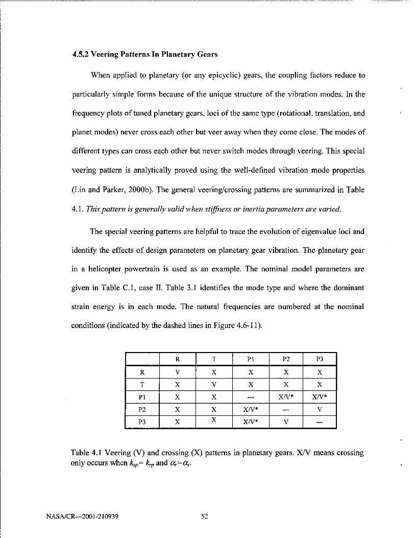
4.5.2 Veering Patterns In Planetary Gears
When applied to planetary (or any epicyclic) gears, the coupling factors reduce to
particularly simple forms because of the unique structure of the vibration modes. In the
frequency plots of tuned planetary gears, loci of the same type (rotational, translation, and
planet modes) never cross each other but veer away when they come close. The modes of
different types can cross each other but never switch modes through veering. This special
veering pattern is analytically proved using the well-defined vibration mode properties
(Lin and Parker, 2000b). The general veering/crossing patterns are summarized in Table
4.1. This pattern is generally valid when stiffness or inertia parameters are varied.
The special veering patterns are helpful to trace the evolution of eigenvalue loci and
identify the effects of design parameters on planetary gear vibration. The planetary gear
in a helicopter powertrain is used as an example. The nominal model parameters are
given in Table C.l, case II. Table 3.1 identifies the mode type and where the dominant
strain energy is in each mode. The natural frequencies are numbered at the nominal
conditions (indicated by the dashed lines in Figure 4.6-11).
R T PI P2 P3
R V X X X X
T X V X X X
PI X X — x/v* X/V*
P2 X X x/v* — V
P3 X X x/v* V —
Table 4.1 Veering (V) and crossing (X) patterns in planetary gears. X/V means crossing only occurs when ksp= k^ and 0^-0,.
NAS A/CR—2001-210939 52

x10
10* kp(NVm)
Figure 4.7 Natural frequencies versus the planet bearing stiffness kp. The planet mode 11 (pure tangential type PI) crosses the planet mode 15 (no tangential motion type P2). The nominal conditions (dashed line) are listed in Table C.l, case II.
Mesh stiffnesses ksp, krp (Figure 4.6and 4.8) have little influence on the low natural
frequencies coj-eojo. This is because these modes are governed by bearing stiffnesses
(Table 3.1) that are much smaller than the mesh stiffnesses. Modes 15-18 have large
strain energy in the sun-planet meshes and are affected by ksp (Figure 4.6); modes 11-14
have substantial strain energy in the ring-planet meshes and are affected by krp (Figure
4.8). When ksp is reduced from the nominal value, the changing C0i5~C0i8 approach the
a>n~G)i4 loci. Because loci of the same type can not intersect, veering occurs between
rotational modes 18 and 14, translational mode pairs (16,17) and (12,13), and planet
NASA/CR—2001-210939 53
modes 15 and 11. Below the veering zones (ksp<100 N/jum), modes 11-14 are very
similar to modes 15-18 above the veering zones (ksp>800 N/jum). In the same way, one
can predict the trend of frequency loci as k,v is increased (Figure 4.8). Using the derived
veering patterns and modal properties, the actual modes affected by varying parameters
can be detected easily although the plots are complicated by veering phenomena.
Support stiffnesses h, h,„ h=c,r,s of the carrier, ring, and sun can vary over a wide
range depending on the configuration (fixing or floating these components). Rotational
and planet modes are independent of the transverse support stiffness h because they have
no translation of the carrier, ring, and sun; only translational modes are affected by
changes in h (Figure 4.9a,b). Considering the veering effects, h significantly affects only
one pair of translational modes with dominant strain energy in the transverse supports.
When the rotational support stiffnesses h„ are altered, similar results are obtained (Figure
4.9c,d), except it is the rotational modes that are susceptible to hu variations.
Altering planet parameters affects most natural frequencies as all modes involve
planet deflections, in general. Applying the derived veering results, five pairs of veering
are identified for changing planet bearing stiffness in Figure 4.7: rotational modes 8 and
18, 4 and 14, translational modes (9,10) and (16,17), (6,7) and (12,13), and planet modes
5 and 15. For large stiffness kp>5000 N/jum, eight natural frequencies increase rapidly to
outside the range of interest. Planet mass mp and moment of inertia Ip also have
significant influence on the natural frequencies (Figure 4.10).
NASA/CR—2001-210939 54

4.6 Discussion and Summary
Eigenvalue loci veering also occurs when degenerate modes of symmetric system
are separated by small disorders. In planetary gears, the cyclic symmetry can be broken
by differing mesh stiffnesses at each planet mesh, manufacturing variations, and
assembly errors. For cyclically symmetric or periodic systems with small disorders and
weak structural coupling, mode localization often accompanies eigenvalue loci veering
(Pierre, 1988). Planetary gears have relatively strong coupling between the planets
through the carrier and teeth meshes, so strong mode localization is unlikely even in the
presence of loci veering. After examination of many cases with various configurations
and parameters, the authors have not found a realistic example of mode localization in
planetary gears.
The special veering patterns of planetary gear eigenvalue loci are easily
summarized. Two approaching eigenvalue loci of the same type (rotational mode,
translational mode, and planet mode) veer away while two loci of different mode types
cross each other. The mode shapes are exchanged across the veering zone. In the veering
zone, the modes are strongly coupled and markedly different than outside the zone. One
can expect significant differences in response from these changed modes. These rules
result from planetary gears' unique modal properties and apply to all design parameters.
The effects of key design parameters are summarized below:
NASA/CR—2001-210939 55

1. Mesh stiffness. ksp and kn, each control three different natural frequencies associated
with one rotational mode, one pair of translational modes, and one group of planet
modes. Dominant strain energy occurs in the tooth meshes of these vibration modes.
2. Carrier, ring, and sun parameters, ky, and fa,,, h=c,r,s each affect only one natural
frequency. The transverse stiffness ky, controls one pairs of translational modes and the
torsional stiffness km, controls one rotational mode. Floating or fixing the carrier, ring, or
sun has limited influence on planetary gear modal properties. The carrier, ring, and sun
masses and moments of inertia affect the same frequencies as their corresponding support
stiffness, though the frequencies vary in the opposite direction.
x10
.</> 5
18R \
16.17T i J
15P ____J^^Cl3T
^—" i normina!
" !
.
10 k (N/nm)
10
Figure 4.8 Natural frequencies versus the ring-planet mesh stiffness k,p. Loci 12-14 will veer with loci 16-18 when krp is further increased. The nominal conditions (dashed line) are listed in Table C.l, case n.
NASA/CR—2001-210939 56

3. Planet parameters. Planet bearing stiffness and planet inertia are the most influential
parameters and affect most natural frequencies. A stiff planet bearing can be beneficial
for resonance tuning because it substantially reduces the number of natural frequencies
in the lower frequency range that is commonly of most interest.
10
55" 6
3 4
x10
(a)
■ ' ■■!■■■■ \
-"16,17T ' I
12.13T1
9,10T>- I
6,7T l 9 0j I
' . I
10
'S" 6 ■5 CO
~S 4
x10
10' k (N/|im)
10'
^18R____.
■
14R
. 8R,
-48 '■ 1Q __
10' 10° ksu (N/nm)
10'
10
«T 6
3 4
x10
(b)
16.17T
12.13T
^
9.10F ^^^ 6,7T '
2 3T ______—— ,
10
3» 6
5 ¥ 4
(d) „
10'
x10
10'
10'
10° kc (N/|xm)
10*
18R
"MR
~^^^ 4R
10° kcu (N/nm)
10'
Figure 4.9 (a), (b) kh,h=s,c only affect translational modes, (c), (d) khu, h=s,c only affect rotational modes. The nominal conditions (dashed line) are listed in Table C.l.
NASA/CR—2001-210939 57

x10
10
8
T 4
2 (a)
0
x10
10
8
(b)
0.2
0.5
0.4 0.6 mp (kg)
lp (kg-m^)
0.8
1.5
x10
2 •3
Figure 4.10 Natural frequencies versus (a) the planet mass mp, (b) the planet moment of inertia Ip. The nominal conditions (dashed line) are listed in Table C.l.
NAS A/CR—2001-210939 58

CHAPTER 5
PARAMETRIC INSTABILITY FROM MESH STIFFNESS VARIATION
In previous chapters, the mesh stiffnesses are considered constant. Current work
investigates the impacts of mesh stiffness variation on planetary gear dynamics. The
variation of mesh stiffness gives rise to a parametric excitation. The linear, time-varying
system studied herein is governed by a set of coupled Hill's equation
Mq + [K0+Kv(O]q = F(O (5.1)
where Ko is the mean stiffness matrix and Kv(t) is the variational part of the stiffness
matrix. F(t) is the external excitation. Kv(t) is periodic with frequency Q (mesh
frequency). Mesh stiffness depends on element compliance, tooth error, profile
modification, transmitted torque, and the position of contact (Kasuba and Evans, 1981).
When Kv(t) is simple harmonic in t, (5.1) becomes a set of coupled Mathieu equations.
The parametric excitation from Kv(t) causes instability and severe vibration when
harmonics of the excitation frequencies are close to particular combinations of the natural
frequencies. Three types of instability are of most interest: (1) primary instability Q~2cOp,
(2) secondary instability Q~(Op, and (3) combination instability Q-cOp+cotj. The objective
of this study is to systematically determine the operating conditions leading to parametric
NASA/CR—2001-210939 59
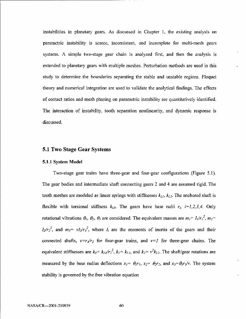
instabilities in planetary gears. As discussed in Chapter 1, the existing analysis on
parametric instability is scarce, inconsistent, and incomplete for multi-mesh gears
systems. A simple two-stage gear chain is analyzed first, and then the analysis is
extended to planetary gears with multiple meshes. Perturbation methods are used in this
study to determine the boundaries separating the stable and unstable regions. Floquet
theory and numerical integration are used to validate the analytical findings. The effects
of contact ratios and mesh phasing on parametric instability are quantitatively identified.
The interaction of instability, tooth separation nonlinearity, and dynamic response is
discussed.
5.1 Two Stage Gear Systems
5.1.1 System Model
Two-stage gear trains have three-gear and four-gear configurations (Figure 5.1).
The gear bodies and intermediate shaft connecting gears 2 and 4 are assumed rigid. The
tooth meshes are modeled as linear springs with stiffnesses ku, ka. The anchored shaft is
flexible with torsional stiffness kio. The gears have base radii r„ i=l,2,3,4. Only
rotational vibrations Oj, 62, O3 are considered. The equivalent masses are nii~ Ij/rj , m?=
h/i"2 , and ms= vl^/rf, where /, are the moments of inertia of the gears and their
connected shafts, v=r/r? for four-gear trains, and v=l for three-gear chains. The
equivalent stiffnesses are ko= ht/rf, kj= ku, and &?= Vkn. The shaft/gear rotations are
measured by the base radius deflections xj= Ojrj, x?= 62V2, and x^Qy^/v. The system
stability is governed by the free vibration equation
NASA/CR—2001-210939 60
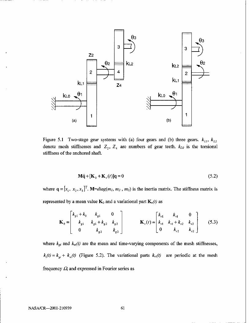
03
Z2
\.
kn
kLO ^01
(a)
62 kL2
Z4
^ ^
kL2
kn
kLO ^01
(b)
63
62
Figure 5.1 Two-stage gear systems with (a) four gears and (b) three gears. kL1, kL2
denote mesh stiffnesses and Z2, Z4 are numbers of gear teeth, kio is the torsional stiffness of the anchored shaft.
Mq + [K0+Kv(O]q = 0 (5.2)
where q = [x15 x2,x3]T. M=diag(mi, ni2 , nt3) is the inertia matrix. The stiffness matrix is
represented by a mean value KQ and a variational part K.v(t) as
(5.3)
where kgi and k^t) are the mean and time-varying components of the mesh stiffnesses,
k/t) = kgi+ kjt) (Figure 5.2). The variational parts kvi(t) are periodic at the mesh
frequency Q\ and expressed in Fourier series as
*gl ~*~ *0 *,1 0 Ki Kr 0
K0 = *«i kgl + kg2 *«2 Kv(/) = K\ Ki+ Ki kv2
0 kg2 kg2 _ 0 K2 Ki _
NASA/CR—2001-210939 61

kYi(0 = 2ka,Yj(all)smsQit + bl')cossQ,t), i = l,2 (5.4) 1=1
where 2kai is the peak-to-peak amplitude of kvi (Figure 5.2). The mesh frequencies Qj and
Ü2 are related by Qi=RQ2, where R=Z2/Z4 and Z?, Z4 are the numbers of teeth on gears 2
and 4 (Figure 5.1a). Note R=l, Qi=Q2 for three-gear systems (Figure 5.1b). Mesh
stiffness variation is obtained through measurement, calculation, or simple specification
(e.g., sinusoidal or rectangular wave). For spur gears, rectangular waves are often used to
approximate the mesh stiffness alternating between n and n+1 pairs of teeth in contact
(Kahraman and Blankenship, 1999a). In this study, the kvi are specified as rectangular
waves with variational amplitudes kai, periods 7, =Qj/2n, contact ratios c„ and phasing
anglesp{Tj (Figure 5.2b). Thus,
aP = -—sm[ln(ct -2/?,)]sin(/^,), 2>,(/) =-—cos[/;r(c,. -2^,)]sin(/^,) (5.5) In In
in (5.4) for 1 = 1,2, ■■■. Without loss of generality, one can specify pj=0, p2=h (h is
called mesh phasing). In practice, the first three or four Fourier terms reasonably
approximate the mesh stiffness variation.
For the time-invariant case, the eigenvalue problem associated with (5.1) is
Ko0, = cofMfa. The vibration modes $ are normalized as <5TM<I>=I with 0=[^;, <fc, (fa].
Applying the modal transformation q = Ou and using (5.4), equation (5.2) becomes
r=\ 1=1
+ 2f2(F„(,') sin/Q2f + G% cos/Q2f)K = 0, n = 1,2,3
where ei = kai /£ ., i=l, 2 and the matrices D, E, F, G are
(5.6)
NASA/CR—2001-210939 62

A ki(t)
kmax /
double tooth contact
kgi .
\ single tooth contact
A kvi(t) -►( piTi
kai
(Ci-1)Ti
-kai Ti: =Qi/(2rc)
Figure 5.2 Modeling of mesh stiffnesses kj(t) = kgi +kvi{t). c, are contact ratios, kg are
average mesh stiffnesses, and pfTj are phasing angles.
D(/)=£gl<X>r
F(/) = kg2®T
0
0
0 0 0
<D
a'2 a'2
i i
0
0
0 0 0
o
0 0 0
:U)=kgl®T 0 b[ b[
0 b[ b[
"0 0 0 (,) = kg2& 0 b[ b\
0 b\ b[
o
o
(5.7)
Equation (5.6) is a set of coupled Hill's equations subjected to multi-frequency
parametric excitations from two gear meshes.
NASA/CR—2001-210939 63

5.1.2 Conditions of Parametric Instability
Parametric instability depends on the frequency, amplitude, and shape of the
parametric excitations. In gear systems, these factors are directly associated with the
operating speed and gear design parameters such as contact ratio, facewidth, diametral
pitch, pressure angle, material properties, and so on. The corresponding model
parameters are the stiffness variation amplitudes kai, ka2, mesh frequencies Q\, £??,
contact ratios c\, ci, and mesh phasing h.
The variation amplitudes kaj are assumed small compared to the average mesh
stiffnesses kgi, so £,= kai/kgi «1 in (5.6). At this point, £7=£?=£is specified; the case of
£]^£2 is discussed later. Using the method of multiple scales, three different mesh
conditions are examined.
1. Three-gear Systems: Equal Mesh Stiffness Variations
In three-gear systems (Figure 5.1b), the two meshes have the same mesh
frequencies Q.x = Q,2 = Q.. We consider the case where the gear facewidths and material
properties, which primarily determine mesh stiffness for a given number of teeth in
contact, are such that the amplitudes of mesh stiffness variation are the same at the two
meshes (£x = e2 = e). The contact ratios and mesh phasing are allowed to differ between
the two meshes, however. In practice, the contact ratios are changed using center
distance, diametral pitch, pressure angle, tooth addendum, and other parameters. The
mesh phasing depends on the layout of the gears and the numbers of teeth.
NASA/CR—2001-210939 64
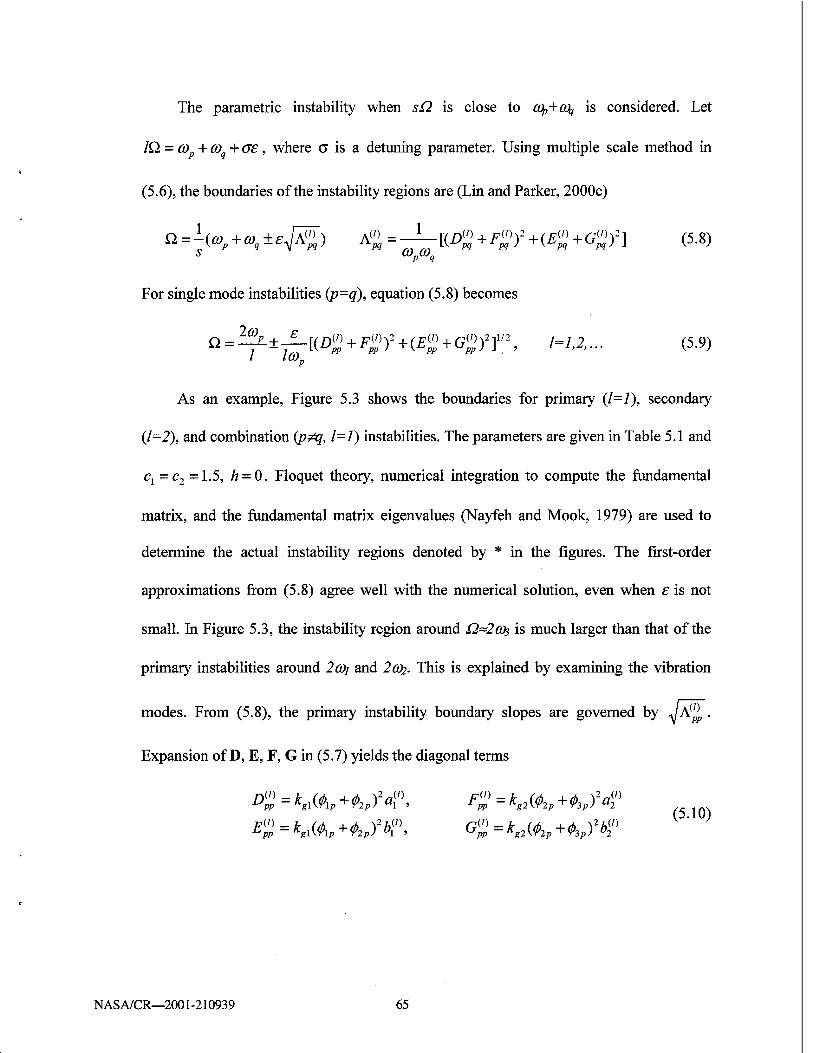
The parametric instability when sQ is close to Cfy+CQj is considered. Let
IQ. = cop + (Oq + oe, where a is a detuning parameter. Using multiple scale method in
(5.6), the boundaries of the instability regions are (Lin and Parker, 2000c)
Q = kcop + a>q±£^) Jt»=-±-[(I%+F%fHE%+G%)2] (5.8) <op%
For single mode instabilities (p=q), equation (5.8) becomes
n = ^±^[(B%+F%)2HE%+(%)2r2> l=1>2>- (5-9)
As an example, Figure 5.3 shows the boundaries for primary (1=1), secondary
(1=2), and combination (p^q, 1=1) instabilities. The parameters are given in Table 5.1 and
Cj =c2 =1.5, h = 0. Floquet theory, numerical integration to compute the fundamental
matrix, and the fundamental matrix eigenvalues (Nayfeh and Mook, 1979) are used to
determine the actual instability regions denoted by * in the figures. The first-order
approximations from (5.8) agree well with the numerical solution, even when £ is not
small. In Figure 5.3, the instability region around Q~2(Os is much larger than that of the
primary instabilities around 2o)j and 2a>2. This is explained by examining the vibration
modes. From (5.8), the primary instability boundary slopes are governed by -JA^, .
Expansion of D, E, F, G in (5.7) yields the diagonal terms
(5.10)
NASA/CR—2001-210939 65

where fap, fap, fap are the gear rotations in mode (pp. Let Sip=fap+fap =Xj+xi be the
relative deflection of the first mesh in mode (pp. Similarly, S2P-fap+fap =X2+xs represents
the modal deflection in the second mesh. For the primary instability boundary around
2cOp, insertion of (5.10) into (5.8) yields
The mesh deflections Si, & in each mode can be observed from the mode shapes (Figure
5.4). The two meshes in fa are both in phase and have smaller Si, SJ than those of fay
where the two meshes are both out of phase. Thus, A']] > A'/J and the instability
boundaries around 2 CO3 have larger slope than those around 2a>i. Mode fa has one mesh in
phase and the other out of phase, so the size of its primary instability regions is between
that of fa and fa (A33 > A^ > A*-/!). In addition, the mesh deflections in a vibration mode
are related to the modal strain energy Ul = k1S2 /2, U2 = k28\ 12. Examination of (5.11)
shows that vibration modes with more strain energy in the meshes have larger instability
regions and are more susceptible to parametric excitations. The above results apply for
mesh stiffness variations of arbitrary shape.
For mesh stiffnesses having rectangular waveforms, one can clearly identify the
effects of contact ratios and mesh phasing on the instability regions. Use of (5.5) in (5.11)
yields
A(^ = [k2Jl sin2 (c,*) + k2g2S2\ sin2 (c2*) +
2_,2 (5-12)
K(0„ 2kglkg2S?pS2psm(c17T)sm(c2x)cos(cl -c2 +2h)7t]{——)2
p
NASA/CR—2001-210939 66

Inertia mi=l, m2=0.3, ni3=4.0
Average mesh stiffness ltgl = Kg2=l
Shaft stiffness k0=0.5
Contact ratio 1< a, c2 < 2
Mesh phasing pj=0, 0<p2=h<l
Variational amplitude 0< kai, ha <0.5
Table 5.1 Parameters of an example system in Figure 5.2.
JO ■D
-"~H
-S= d H X I X J stable
T" *■ .
unstable
-J
(0,+0),
-w1+(0.
»o ....
2»2 1 £ $
co1+W?
$ t
% $ —%
2a»,
roi
^F # $ —*
i 1 1 i
* *
0.05 0.1 0.15 0.2 e=k/k
a 9
0.25 0.3
Figure 5.3 Instabilities regions when Q,1 = Q2=Q,£l=s2=£; — analytical solution;
*** numerical solution. The parameters are from Table 5.1 and cx = c2 = 1.5, h = 0.
NASA/CR—2001-210939 67

The minimum value A(*' = 0 is obtained when sinCj/r = sinc2;r = 0 and the unstable region
vanishes. This is achieved for integer contact ratios cy, c2 where the number of tooth pairs in
contact remains constant and mesh stiffnesses are time-invariant. For given, non-integer c12
between 1 and 2, A^p is minimized by setting cos(Cj - c2 + 2h)7t = -1 or c, - c2 + 2h = ±1,3 .
By properly choosing the contact ratios and mesh phasing, the parametric instability regions can
be dramatically reduced. Figure 5.5 compares the instability regions for three cases. The most
severe condition for primary instabilities (dash-dot lines) is cx — c2 =1.5 and h = 0, which
maximizes JsP in (5.12). This condition is markedly improved by changing the phasing h = 0.5
so that Cj - c2 + 2h = 1 (dashed lines). When the contact ratios are close to integers (solid lines,
c?! =1.1, c2 = 1.9, h = 0.4), the primary instability region becomes even smaller.
Similar conditions are obtained for secondary and combination instabilities (Lin
and Parker, 2000c). Unfortunately, the primary, secondary, and combination instability
regions cannot be minimized at the same time. The conditions reducing the primary
instability regions (dashed lines, Figure 5.5) result in large combination instability
regions, and vice versa (dash-dot lines). Depending on specific applications, a trade-off
may be made to reduce multiple instability regions, though none are true minima (solid
lines). Adjusting contact ratios and mesh phasing is clearly an effective means to
minimize instability regions and avoid resonances under operating conditions.
2. Four-gear Systems: Equal Mesh Stiffness Variations
Two-stage countershaft systems (Figure 5.1a) have two different mesh frequencies Qi=RQ2,
which means more instability regions than three-gear systems. We consider the case where the
NASA/CR—2001-210939 68

gear facewidth and material are such that the mesh stiffness amplitudes are identical at the two
meshes (S]=£2=£), although the contact ratios and phasing are not restricted. Depending on the
ratio R=Z2/Z4, the parametric instability regions associated with 12; and Q2 may overlap each
other. For R = m/j (m, j are integers), the l=j instabilities (single mode and combination) of Q\
and the l=m instabilities of Q2 occur simultaneously. Because their instability regions are
typically the largest, the interactions involving either m or/-/ are of most interest.
(|>i (coi=0.237)
Figure 5.4 Vibration modes for the time-invariant system with parameters in Table 5.1.
NASA/CR—2001-210939 69
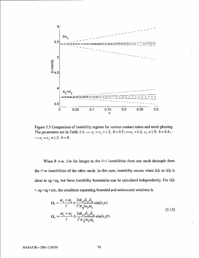
t>
5.5
2<°3 _,...,.,.- — -"""""
5
—'—■-._
-52 to
G 4.5
4 «W _ --
3.5 ' i i i i -i
0.05 0.1 0.15 e
0.2 0.25 0.3
Figure 5.5 Comparison of instability regions for various contact ratios and mesh phasing. The parameters are in Table 5.1.— ^=^=1.5, h = 0.5;—Cj =1-1, c2=1.9, ^ = 0.4;-
—-Cj =c2 =1.5, h = 0.
When R ^ m, 1/m for integer m, the 1=1 instabilities from one mesh decouple from
the l=m instabilities of the other mesh. In this case, instability occurs when IQi or IQ? is
close to (Op+COq, but these instability boundaries can be calculated independently. For lüj
= cq,+Cfy+£<Ji, the condition separating bounded and unbounded solutions is
Q1=^4^±^Asin(/^) / l2n^copcoq
a2--£ co„ + co„ 2ek~ö,„ö-
(5.13)
/ - + ■ gl 2p 2q
l2n^ «V», sin(lc27r)
N AS A/CR—2001-210939 70

The stability regions associated with each mesh frequency depend on the individual
contact ratios but are independent of mesh phasing as the two mesh excitations are
uncoupled. For primary and combination instabilities (1=1), maximum regions occur
when c1=c2= 1.5 and minimum regions require c1=c2={l,2}. For secondary
instabilities (1=2), the maximum and minimum conditions are cx = c2 = {1.25, 1.75} and
cx =c2 ={1, 1.5, 2}, respectively. Figure 5.6a shows the instability regions for R=3/5.
The primary instability associated with Q2=2o)3+e(72 occurs at Qj =RQ2=R(2(Os+£G2) in
Figure 5.6a.
When R = m or 1/m for integer m, the parametric excitations from the two meshes
interact. Consider the case with R=l/m, where the l=m instabilities caused by Qi overlap
with the primary instabilities caused by Q2- Considering instability of the p-X\\ mode
where &I=2cq/m+£(Ji and Ü2=m£2i=2cOp+meai, the boundaries have
^ = [(/>£> + O2 + (E™ +G2)2]1/2 Kmcop) (5.14)
For example, when Ü2=2Ü] (R=l/2), the boundaries for Qi secondary instabilities
(overlapping with /^primary instabilities) are
Qx =^±^[(^+02+(4?+02]1/2 (5-15)
Figure 5.6b shows instability regions in the (Qj, e) plane for R=l/2. Note the instability
at Q,i~G)$ couples with the instability at U2~2o)3, and the combined instability region is
much larger than the case without interaction (Figure 5.6a). Using (5.5) and (5.10) in
(5.15), the slopes of these boundaries are
NASA/CR—2001-210939 71

<*\ = lkiiSiP sin2(2c^) + k2g2S2p sin2(c2;r)
(5.16) + 2kg:kg2S
2pS2p sin(2cj^) sin(c2^) cos(2Cj -c2 + 2h)7t]U21 cop
Minimization of 0} requires Cj ={1,1.5,2} and c2 ={1, 2} for l<c12<2. The
instability region can also be reduced by adjusting the phasing h according to
cos(2cj -c2+ 2h)K = ±1 with sign the same as sin(2Cj^"). The primary instability regions
under Q\ (1=1) do not coincide with any other instability regions. Other overlap situations
are possible, such as the i2? secondary instability (1=2) overlaps with the Qi fourth
instability (1=4), but the interaction between these higher instabilities is typically weak
and the instablity regions are much smaller. Combination instabilities can be analyzed
similarly.
3. Three and Four-gear Systems: Unequal Mesh Stiffness Variations
This general case allows all parameters of the two mesh stiffnesses to differ. In
contrast with prior cases, the gears may have differing facewidths and material properties
such that the amplitudes of stiffness variation at each mesh vary independently (e^ei).
The contact ratios and mesh phasing are unrestricted. The design of one mesh must
account for dynamic interactions with the mesh stiffness variation of the other.
When R # m, 1/m for integer m, there is no interaction between the parametric excitations
from the two meshes. The Q\ instabilities are only affected by £7 and the Q2 instabilities
are only affected by f?.
When R = m or 1/m for integer m, a mode may be simultaneously driven to
instability by both mesh excitations. In this case, the first mesh instability regions can be
significantly affected by the presence of £? and vice versa. Closed-form boundaries of the
NASA/CR—2001-210939 72

form (for primary instability) Qi = 2ojp+£iGi+£2<J2 for independently varying £j, £2 are
cumbersome. Alternatively, simple yet accurate approximations for the instability
boundaries are obtained by presuming a linear variation of the boundaries in the (12;, £2)
plane for given £2. To construct this linear approximation, one point is calculated under
the condition £1=0,£2—C and a second point is obtained at £1=£2=C. The primary
stability boundary limits for £x = 0,£2 = C are
ß, = 2cop ± —[(/£>)' +(Gg)T2 (5-17)
From (5.9), the stability boundary limits for £x = C,£2 = C are
O, = 2cop ±—[{DV+F%? HE'S + G«)2]1'2 (5.18)
An example is for the primary instability when R=l, C=0.3. Connecting the two
points obtained from (5.17) and (5.18) yields the instability boundaries, which agree well
with the numerical solution (Figure 5.7a). Assembling the (£2j, £]) planes for various £2=C
generates three-dimensional plots of Qi versus £1, £2 (Figure 5.7b). The parametric
excitation in the second mesh dramatically changes the shapes of the instability regions.
Notice that the second parametric excitation widens the primary instability region for
small £j compared to mono-frequency excitation (Figure 5.3). In contrast, the
combination instability at Q1&CO2 +0)3 disappears near £j=0.23 in Figure 5.7a. In other
words, an otherwise unstable system is stabilized by the presence of a second parametric
excitation. The solid line in Figure 5.7b indicates points where the CO2+CO3 combination
instability vanishes.
NASA/CR—2001-210939 73

5.5
~4.5 ■o
(a)
3.5
2.5
2Ro>„
=XZ^_i
"1
0.05 0.1 0.15 0.2 0.25 0.3 £
5.5
~4.5
3.5
2.5
(b)
1
=HH_L_1_ 0.05 0.1 0.15 0.2 0.25 0.3
e
Figure 5.6 Instabilities regions when Q, = RQ2, £x=£2=£. (a) R=3/5, (b) R=l/2. The
parameters are in Table 5.1 and Cj = c2 = 1.5, h = 0.*** denotes numerical solutions.
N AS A/CR—2001-210939 74

0 0
(b)
Figure 5.7 Instabilities regions when Qi=Q2- (a) Qi vs. £\ and £2=C=0.3. (b) Qj vs. £j, £2 and the solid line indicates vanishing of the combination instability. The parameters are in Table 5.1 and c, = c, = 1.5, h = 0.
NASA/CR—2001-210939 75

5.1.3 An Example
The two-stage gear system (Figure 5.1a) studied by Tordion and Gauvin (1977) and
Benton and Seireg (1980b) is used as an example. These two papers come to markedly
different conclusions as discussed below. The system parameters are given in Table 5.1
and Cj =1.47, c2 =1.57. In keeping with the published work, the double-tooth contact
mesh stiffness kmax=l is kept constant, and the average mesh stiffnesses kgi decrease as kai
is increased (Figure 5.2b).
Tordion and Gauvin assumed that kvj and kv? have the same amplitude and
frequency but different contact ratios and phasing. They applied an infinite determinant
method (Bolotin, 1964) to plot the boundaries of primary and secondary instabilities
(dashed lines in Figure 5.8). Their results deviate significantly from the numerical
solution as a result of analytical errors. In addition, the Fourier expansion they derived for
rectangular waveforms (equations (11) and (12) in Tordion and Gauvin, 1977) is
incorrect. Nevertheless, they conclude that "The phase displacement between the
meshing stiffnesses has a great influence on the width of the instability regions."
Benton and Seireg (1980b) considered the same system. They decoupled the
equations using the modal transformation and neglected the off-diagonal terms of the
transformed time-varying stiffness matrix (that is, <bTKv(0<&). These treatments reduce
(5.6) to three uncoupled Mathieu equations. The average value of two contact ratios was
used to make the stiffness variations kvi and kvi identical. With these approximations,
they conclude that the instability regions are independent of the mesh phasing, that is,
"the normal mode technique ... without considering the phase variations ... provide(s) a
NASA/CR—2001-210939 76
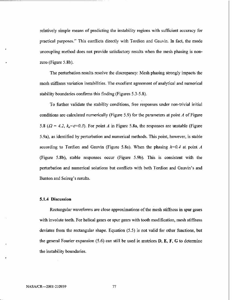
relatively simple means of predicting the instability regions with sufficient accuracy for
practical purposes." This conflicts directly with Tordion and Gauvin. In fact, the mode
uncoupling method does not provide satisfactory results when the mesh phasing is non-
zero (Figure 5.8b).
The perturbation results resolve the discrepancy: Mesh phasing strongly impacts the
mesh stiffness variation instabilities. The excellent agreement of analytical and numerical
stability boundaries confirms this finding (Figures 5.3-5.8).
To further validate the stability conditions, free responses under non-trivial initial
conditions are calculated numerically (Figure 5.9) for the parameters at point A of Figure
5.8 (£2 = 4.2, ka-£=0.3). For point A in Figure 5.8a, the responses are unstable (Figure
5.9a), as identified by perturbation and numerical methods. This point, however, is stable
according to Tordion and Gauvin (Figure 5.8a). When the phasing h=0.4 at point A
(Figure 5.8b), stable responses occur (Figure 5.9b). This is consistent with the
perturbation and numerical solutions but conflicts with both Tordion and Gauvin's and
Benton and Seireg's results.
5.1.4 Discussion
Rectangular waveforms are close approximations of the mesh stiffness in spur gears
with involute teeth. For helical gears or spur gears with tooth modification, mesh stiffness
deviates from the rectangular shape. Equation (5.5) is not valid for other functions, but
the general Fourier expansion (5.6) can still be used in matrices D, E, F, G to determine
the instability boundaries.
NASA/CR—2001-210939 77

If damping is considered, the system stability improves and the instability regions
shift to the right in the (Q, £) plane. Furthermore, damping and non-linearity (e.g., tooth
separation) must be considered to determine the limit cycle amplitude of the dynamic
response when operating conditions cause instability.
The instability analysis can be reduced to single mesh gears with one natural
frequency (0„. From (5.9), primary and secondary instabilities vanish as the contact ratio
Ci-{1,2} and Cj={l, 1.5, 2}, respectively. Maximum primary and secondary instability
occurs at a=1.5 and ci={1.25, 1.75}, respectively. Kahraman and Blankenship (1999)
experimentally studied a pair of spur gears under mesh stiffness excitation for various
contact ratios. They showed that the amplitude A] in the first mesh frequency harmonic of
the response is minimized when the contact ratio C]={1.0, 2.0}. This is because
parametric excitations are eliminated for integer contact ratios. When the mesh frequency
Q~(On, their measured A] reaches maximum for cj-1.4. A possible explanation for the
high A] at this contact ratio is due to the combined effects of primary and secondary
instabilities. First, for both primary instability excited by the first harmonic of k(t) and
secondary instability excited by the second harmonic of k(t), the dominant response
frequency is C0n. We now examine the contact ratios where both instabilities are active.
Although the maximum primary instability region occurs at a=1.5, the secondary
instability region is eliminated there. For ci=1.25, the secondary instability region is
maximal but the primary instability region is small. For a~1.4 (average of 1.25 and 1.5)
or 1.6 (average of 1.75 and 1.5), however, both primary and secondary instabilities have
significant instability regions. Generally, the larger an instability region, the higher
NASA/CR—2001-210939 78
response amplitude occurs due to this instability (to see this heuristically, note that both
the slope of the stability boundaries in (17) and excitation of first order response in (10)
are proportional to the same quantities D, E, F, and G). Accordingly, for ci~1.4 and 1.6,
both instabilities induce large response and jointly contribute to large Aj. When the mesh
frequency £2-2C0n (not shown in Kahraman and Blankenship, 1999), the instability is
caused only by primary instability excited by the first harmonic of k(t). Because the
primary instability region is maximal at ci=1.5, the response amplitude Aj around Q~2co„
also becomes maximal. Therefore, from the viewpoint of dynamic instability and
amplitude, contact ratios in the range 1.4-1.6 are harmful to single-mesh gears at high
speeds.
5.2 Planetary Gear Parametric Instability
Planetary gears have multiple time-varying mesh stiffnesses and their parametric
instability has not been analytically investigated. In planetary gears, parametric
excitations are complicated as different contact ratios and phasing conditions exist
between the sun-planet and the ring-planet meshes. The objective of this study is to
analyze parametric instability excited by different time-varying mesh stiffnesses in
planetary gears. The perturbation method used for two-stage gears is extended to
planetary gears that have degenerate vibration modes due to their cyclic symmetry. The
well-defined modal properties of planetary gears are used to derive simple expressions
for instability boundaries separating the stable and unstable regions. From these
expressions, the effects of contact ratios and mesh phasing are analytically determined to
NASA/CR—2001-210939 79

(a)
(b)
Figure 5.8 Comparison of instability regions. The parameters are from Table 5.1, Cj=1.47, c2=1.57, and phasing (a) h=0, (b) h=0.4. — Perturbation method; ***
Numerical method; — Tordion and Gauvin (1977); Benton and Seireg (1980b).
NASA/CR—2001-210939 80

10 20 30 40 50 60 70
(a)
10 20 30 40 50 60 70 80
(b) 40 60
t (sec)
Figure 5.9 Free responses for Q = 4.2, ka=£=0.3 (point A in Figure 5.8) and the parameters of (a) Figure 5.8a and (b) Figure 5.8b. The initial conditions are
NASA/CR—2001-210939 81
provide insight into planetary gear design. In practice, planet mesh-phasing schemes are
often applied to cancel or neutralize resonant response at speeds where the mesh
frequency is near a natural frequency (Seager, 1975; Kahraman, 1994b; Kahraman and
Blankenship, 1994; Parker, 2000). In this same spirit, this study shows that particular
parametric instabilities can be eliminated under certain phasing conditions that can be
achieved by proper selection of design parameters. Tooth separation nonlinearity induced
by parametric instability is numerically simulated.
5.2.1 System Model and Mode Properties
The planetary gear dynamic model used is based on the one developed in Chapter 2
(Figure 2.2). Translational degrees of freedom in that model are eliminated, and only
rotational motions of the gear bodies are considered. The sun-planet and ring-planet tooth
meshes are modeled as linear springs with time-varying stiffnesses ks„(t), kn,(t), n=l,...N.
The system equations of motion are
Mq + K(0q = F (5.19)
M = diag[lc/rc2+Y4mp, Ir/rr
2, IJr2, Ip/r2, -, Iplr2
p]
K(0 =
symmetric
>x -2>„ *rl *sl • •• k -k
I*„ 0 -*,. -k
I*„ *„ ^sN
*rl + *sl 0 ••• 0
0
krN + *sN
(5.20)
NASA/CR—2001-210939 82
q = [uc,ur,us,u1,---,uNJ, F = [Tc/rc, Trlrr, TJrs, 0,---,0f
where the summation index n ranges from 1 to N. In the stiffness matrix K(t), each mesh
stiffness is represented by kjt) = ksp + kln(t), kjt) = krp+ k2n(t), n=l, ...N, where ksp,
kyp are mean values and ki„, k2„ are time-varying components of the n-th sun-planet and
ring-planet meshes. For spur gears, rectangular waves are often used to approximate
mesh stiffnesses alternating between d and d+1 pairs of teeth in contact. Figure 5.10
shows the mesh stiffness variations ki„, fo« with peak-to-peak amplitudes 2kvS, 2k>r,
contact ratios cs, cr, and phasing angles ys„T, (Ysr+YndT- The sun-planet and ring-planet
meshes have the identical mesh frequency Q=27t/T. The sun-planet mesh stiffnesses
between planets differ only by a time transition (or phase angle), and likewise for the
ring-planet meshes. Mesh phasing in planetary gears is determined by planet position
angles ys„ and the numbers of teeth zs, zr, zp for the sun, ring, and planets (Kahraman and
Blankenship, 1994). ysn=\j/rzs/(2K) denotes the mesh phasing between the first and n-th
sun-planet meshes (ysi=0); yn,= \//^r/(27t) is the mesh phasing between the first and n-th
ring-planet meshes (yr]=0); ysr=zp/2 is the mesh phasing between the sun-planet and ring-
planet meshes for each planet. Note ysr=0 for even zp and ysr=l/2 for odd zp. Expansion of
kj„, k2„ in Fourier series yields
*L,(0 = 2*„J>- smlQt + b^ coslQt),
1=1 (5-21> MO = 2*,,f>» sin/^ + ^} cos«*)
7=1
NASA/CR—2001-210939 83
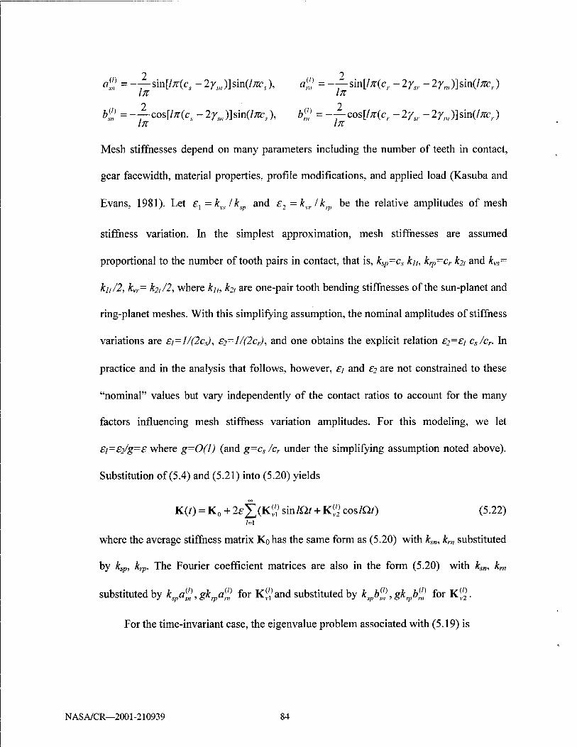
2 2 «1? = -—sm[ln(cs-2ys>,)]sm(lncs), a% =-—sm[!x(cr-2y„-2yni)]sm(lm:l.)
In In 2 2
b% = -—cos[ln(cs - 2ysil)] sin(/^), b% = -—cos[ln(cr - 2ysr - 2ynl)] sin(/;ze,) In In
Mesh stiffnesses depend on many parameters including the number of teeth in contact,
gear facewidth, material properties, profile modifications, and applied load (Kasuba and
Evans, 1981). Let £l = kvslksp and e2 =kvr/kip be the relative amplitudes of mesh
stiffness variation. In the simplest approximation, mesh stiffnesses are assumed
proportional to the number of tooth pairs in contact, that is, ksp-cs k]h krp~cr ki, and kvs=
k],/2, kvr= kji/2, where kn, ki, are one-pair tooth bending stiffnesses of the sun-planet and
ring-planet meshes. With this simplifying assumption, the nominal amplitudes of stiffness
variations are £]=J/(2cs), £2-l/(2cr), and one obtains the explicit relation £?=£/ cs/cr. In
practice and in the analysis that follows, however, £; and £? are not constrained to these
"nominal" values but vary independently of the contact ratios to account for the many
factors influencing mesh stiffness variation amplitudes. For this modeling, we let
£i=£2/g=£ where g=0(l) (and g=cs/cr under the simplifying assumption noted above).
Substitution of (5.4) and (5.21) into (5.20) yields
K(0 = K0 + 2e^(K|,'1) sinlQt + Kl£ coslQt) (5.22)
where the average stiffness matrix Kohas the same form as (5.20) with ks„, k„, substituted
by ksp, krp. The Fourier coefficient matrices are also in the form (5.20) with ks„, k„,
substituted by K/^gk^ for K«and substituted by K/^gk^ for Kg.
For the time-invariant case, the eigenvalue problem associated with (5.19) is
NASA/CR—2001-210939 84

K0(/>,=O)fM^ (5.23)
The natural frequencies and vibration modes have unique properties (3.7), (3.14), (3.20).
We specialize these properties for the case of a rotational vibration model with fixed ring
and L=N+2 degrees of freedom. In this case, all vibration modes can be classified into
one of three categories: (1) a rigid body mode (a>i=0), (2) two modes with distinct natural
frequencies (ߣ, cut), and (3) a group of degenerate modes with multiplicity N-l
(ö%=... =a>N+i)- In the distinct modes, all planets have identical motion
u„=U], n=l,2,...,N (5.24)
In the degenerate modes, the carrier, ring, and sun have no motion, and the planet
rotations satisfy
u„=[u1sm(yf2-yfn) + u2sm\yn]/sm.yf2, n=l,2,...,N (5.25)
These well-defined properties are valid not only for equally spaced planets with position
angles y/„ =2?r(n-l)/N, but also for diametrically opposed planets with I//„+N/2 =y/n+7t.
5.2.2General Expression for Instability Boundaries
We determine the operating conditions (that is, mesh frequency £2 and stiffness variation
amplitude e) that lead to instability when IQ-Cüp+CQq for integer /. The rigid body mode
(ß»;=0) is not excited under operating conditions, and does not affect the instabilities of
other modes. Only the two distinct modes and the group of degenerate modes are
considered in what follows. The parametric instability when IQ is close to Cfy+Cty is
considered. Let lQ. = cop + coq+£<7, where <7 is a detuning parameter to be determined.
From (5.8), when (Op and o\ are both distinct, the instability boundaries are
NASA/CR—2001-210939 85

A kjt) y T ' sn'
Ks"
■K
(cs-1)T
U
A cwur
w; double tooth contact
(Cr-f)T ■■ fc.
-K
single tooth contact
Figure 5.10 Modeling of mesh stiffness variations in the sun-planet and ring-planet meshes. cs, cr are contact ratios, and ysn, y„,, ysr are mesh phasing.
single mode instability: Q. - I lcop^
co„ +co„
pp
combination instability: Q = — ±—y A^ l{o)pO)q)
(5.26)
(5.27)
WbereA«=(D2)2+(JB2)2- pq .
When (Op or (Oq are degenerate, the complexity of instability solutions depends on
the multiplicity of the degenerate natural frequencies. We first study the case with
multiplicity two, say ($=0%. The single-mode instability boundaries for ty,=(fy are (Lin
and Parker, 2000d)
NAS A/CR—2001 -210939 86
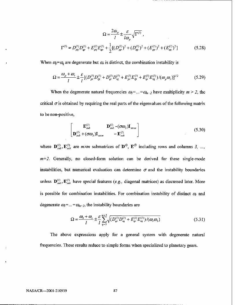
/ IcoJ
T(,) = D%D% + £%£% +1[(Z)S)2 HD^f HE")2 +(E%f] (5.28)
When (Op=o\ are degenerate but a*,- is distinct, the combination instability is
Q = ^^±f[(2><W + Z^ (5.29)
When the degenerate natural frequencies 0)3=...=0^+2 have multiplicity m > 2, the
critical a is obtained by requiring the real parts of the eigenvalues of the following matrix
to be non-positive,
Ej£ Di;i-(cTO3)Imxm
Di:,)i+(cTö>3)I„,xm -E«
»(') !?(') or« 111V111 eiiUmofri/>oo nf Tl'" Ti1'"
(5.30)
where D„;6,E^;Ä are wx>« submatrices of D , E'y including rows and columns 3, ...,
m+2. Generally, no closed-form solution can be derived for these single-mode
instabilities, but numerical evaluation can determine a and the instability boundaries
unless D^,, E^, have special features (e.g., diagonal matrices) as discussed later. More
is possible for combination instabilities. For combination instability of distinct (Or and
degenerate (03=... =0^+2, the instability boundaries are
, m+2 Q = ^^±£S^(W+^(o)/(^3) (5i31)
The above expressions apply for a general system with degenerate natural
frequencies. These results reduce to simple forms when specialized to planetary gears.
NASA/CR—2001-210939 87

5.2.3. Planetary Gear Parametric Instability
Planetary gears' well-defined modal properties are now used to simplify the above
instability conditions to compact expressions suitable for use in applications. Mesh
stiffness are approximated by rectangular waveforms (5.21). Expansion of D^, E^ gives
£>(/)=<zW,V =k YaU)S(p)S{q) + k gYa(l)Sip)S{<l) pq Yp^^vlYq ,;u / . sn sn ^sn ivo / ,nt m vm
N N V '
E{,)=<pTKU)?<p =k Yb(,)S(p)ö{q)+k gYb(nS{p)S(
pq rp v2T(jr sn / ,sn sn sn vroo / ,ni **m n w=l w=l
where S{sp) =us-uc+ un is the deformation of the w-th sun-planet mesh in mode $, and
SlP) = -uc -un is the deformation of the n-th ring-planet mesh. For different spacing and
phasing of planets, matrices D^, E^ have special features that simplify the instability
conditions.
1. Equally spaced planets
For equally spaced planets (y/„ =2n(n-l)/N), the vibration modes have structured
properties (5.24) and (5.25). In this case, (zs+zr)/N = integer and the planet meshes have
phasing ysn=(n-l)zs/Nand yn,=(n-l)zr/N, n=l,...,N. The two possible phasing conditions
are examined below.
(1) In-phase Planet Meshes
Consider the case when all the sun-planet meshes are in-phase {ys„-0, n=l,...,N)
and all the ring-planet meshes are in-phase (y„,=0, n=l, ...,7V). This design is typical when
optimizing load sharing and results when zs and zr are each integer multiples of N.
However, there is a constant phasing ysr=0 (even zp) or 1/2 (odd zp) between the sun-
NAS A/CR—2001 -210939

planet and ring-planet meshes for each planet. The Fourier coefficients a^,a^ ,b^,b^
in (5.21) are independent of the planet index n.
For a distinct natural frequency (Op, vibration mode property (5.24) leads to
$lf = S^ , S{mp) = S™ for any planet n. Using (5.21) and (5.32) on (5.26), the primary
instability boundaries have
,2N A(S = (—f[(S{
slp))\ksp sin^)2 + (S^ik^gsm^f +
K (5.33) 2 KpKsi^d^f sin(^)sin(^r)cos^(Cj - cr + 2ysr)]
Obviously, A(2,= 0 when cs, cr are integers and all instabilities vanish. If cs, cr ^integer, a
second choice to reduce the instability regions is to set the third term in (5.33) to be
negative by adjusting cs, cr, and ysr. From (5.27), the combination instability boundaries
for two distinct modes have
,27V A» = (—)2[(kspS^f sinac,)2 +(M*W sinncr? +
71 (5.34)
2 tJ^WW sin(^)sin(^r)cos^(ci - cr + 2ysr)]
Inertias (kg) Ic/rc2=6, Is/rs
2=2.5, Ip/rp2=2
Planet mass (kg) mp=4
Mesh stiffness (N/m) "■sp~ Krp~lU
Natural frequencies (kHz)
(Oi=0, 0)2=1.212, 0)3=0)4=1.592, 0)5=2.196
Table 5.2 Parameters and natural frequencies of an example planetary gear with fixed ring and three planets.
NASA/CR—2001-210939 89
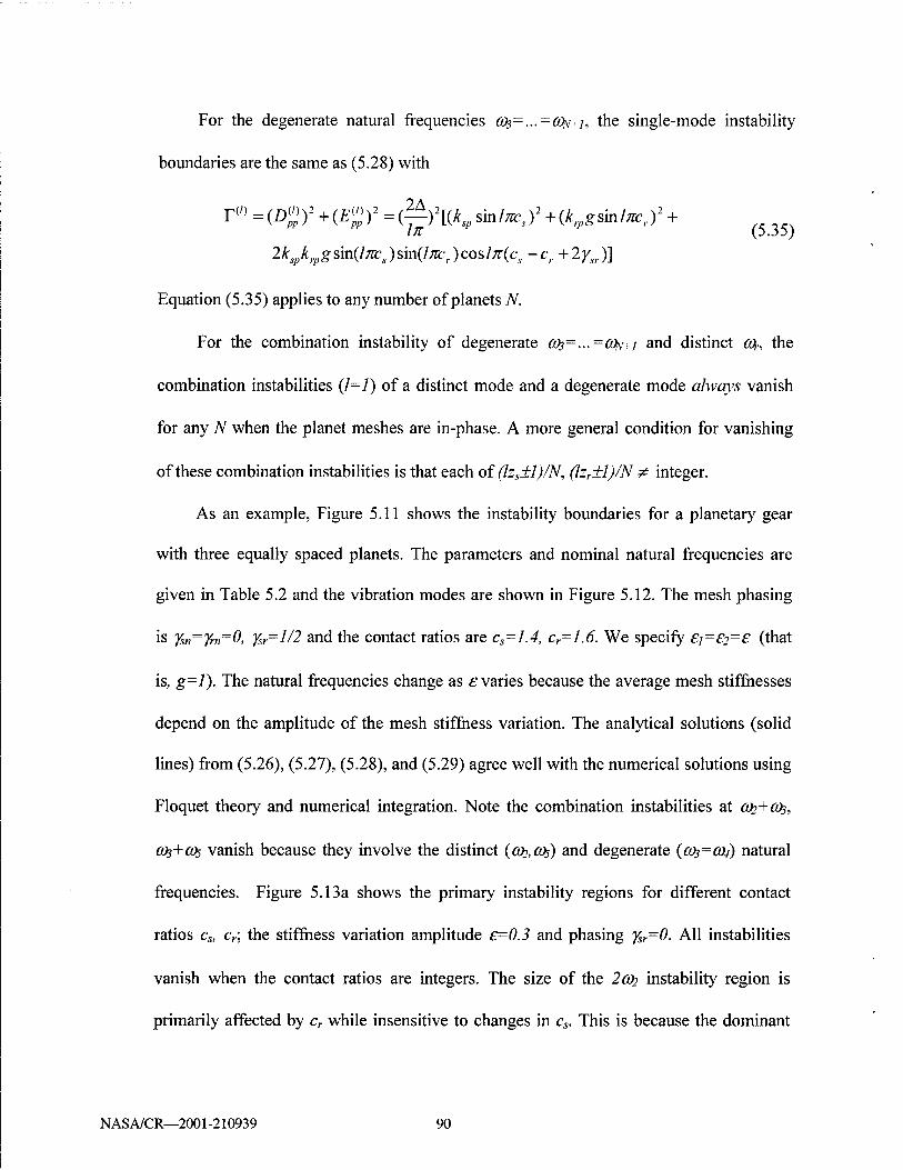
For the degenerate natural frequencies C03=...=0JNI, the single-mode instability
boundaries are the same as (5.28) with
r(/) =(Z>£)2 +(02 =(7^)2[(^ sin/^)2 +(^gsin/^,.)2 +
2*v*ipgsin(/mrJsin(/ÄCl .)cos/;r(c, -c,. + 2^,.)]
Equation (5.35) applies to any number of planets N.
For the combination instability of degenerate OJS=...=OJ^-~I and distinct cot-, the
combination instabilities (1=1) of a distinct mode and a degenerate mode always vanish
for any N when the planet meshes are in-phase. A more general condition for vanishing
of these combination instabilities is that each of (lzs±l)/N, (lzr±l)/N # integer.
As an example, Figure 5.11 shows the instability boundaries for a planetary gear
with three equally spaced planets. The parameters and nominal natural frequencies are
given in Table 5.2 and the vibration modes are shown in Figure 5.12. The mesh phasing
is Ysn-Yrn-0, Ysr=l/2 and the contact ratios are cs=1.4, c,=1.6. We specify £j=£2=£ (that
is, g=l). The natural frequencies change as £ varies because the average mesh stiffnesses
depend on the amplitude of the mesh stiffness variation. The analytical solutions (solid
lines) from (5.26), (5.27), (5.28), and (5.29) agree well with the numerical solutions using
Floquet theory and numerical integration. Note the combination instabilities at ah+Cfy,
CO3+CO5 vanish because they involve the distinct (0)7,0)5) and degenerate ((03=0)4) natural
frequencies. Figure 5.13a shows the primary instability regions for different contact
ratios cs, cr; the stiffness variation amplitude £=0.3 and phasing %r=0. All instabilities
vanish when the contact ratios are integers. The size of the 2o>> instability region is
primarily affected by cr while insensitive to changes in cs. This is because the dominant
NASA/CR—2001-210939 90

deformation of mode <fo occurs in the ring-planet meshes (Figure 5.12). The 2(0$
instability region is mostly affected by cs because most deformation occurs in the sun-
planet meshes for this mode. The primary instability of the degenerate modes at 2cüs=2ca/
is influenced by both cs and cr. The primary instability regions are maximized for
cs-cr=1.5, which is expected from (5.33) and (5.35). The relative phasing ysr between the
sun-planet and ring-planet meshes can have a major impact. When the phasing ysr=l/2
and other parameters are the same as in Figure 5.13a, the 2cos=2co^ instability vanishes
for any cs=cr (Figure 5.13b). This is because T(1) =0 in (5.35) for kSp=krp, g=l and cs=cr.
The above analyses show that contact ratios and mesh phasing significantly affect
the operating condition instability regions. In practice, particular instabilities can be
minimized by proper selection of contact ratios and mesh phasing, which are adjusted by
center distance, diametral pitch, pressure angle, tooth addendum, numbers of teeth, and
other parameters.
(2) Sequentially Phased Planet Meshes
Here we consider equally spaced planet systems where the sun-planet and ring-
planet meshes are sequentially phased with ys„=(n-l)zs /N and ym=(n-l)zr /N. This case
corresponds to zs /N, zr /JV# integer but (zs+zr)/N=integer. A constant phasing ysr exists
between the sun-planet and ring-planet meshes for each planet. For the sequential
phasing, the Fourier coefficients in (5.21) satisfy
il,«;? - TL-2 - II,*» = II,«'=o <5-3«) when lzs/N, lzr/N are non-integer.
NASA/CR—2001-210939 91
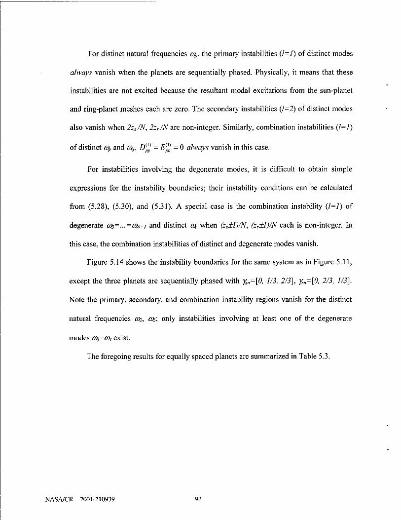
For distinct natural frequencies cq» the primary instabilities (/=/) of distinct modes
always vanish when the planets are sequentially phased. Physically, it means that these
instabilities are not excited because the resultant modal excitations from the sun-planet
and ring-planet meshes each are zero. The secondary instabilities (1=2) of distinct modes
also vanish when 2zs/N, 2zr/N are non-integer. Similarly, combination instabilities (1=1)
of distinct (Op and o\, D^ = E^ = 0 always vanish in this case.
For instabilities involving the degenerate modes, it is difficult to obtain simple
expressions for the instability boundaries; their instability conditions can be calculated
from (5.28), (5.30), and (5.31). A special case is the combination instability (1=1) of
degenerate CöS=...=CüN+I and distinct (Or when (zs±l)/N, (zr+l)/N each is non-integer. In
this case, the combination instabilities of distinct and degenerate modes vanish.
Figure 5.14 shows the instability boundaries for the same system as in Figure 5.11,
except the three planets are sequentially phased with ys„=[0, 1/3, 2/3], Ym=\0, 2/3, 1/3].
Note the primary, secondary, and combination instability regions vanish for the distinct
natural frequencies ah, CO5; only instabilities involving at least one of the degenerate
modes 0)3=0)4 exist.
The foregoing results for equally spaced planets are summarized in Table 5.3.
NASA/CR—2001-210939 92

4.5
3.5
N
i. 3 a
2.5
1.5-
stable unstable
0 0.05 0.1 0.15 0.2 0.25 0.3 e
Figure 5.11 Instability regions for the system in Table 5.2 and in-phase meshes ysn=yrn=0, ysr-l/2. cs=1.4, cr=1.6, £=£i=£2 (g-1). —analytical solution; *** numerical solution.
co,=1592Hz
Figure 5.12 Mode shapes of the system in Table 5.2. The carrier motion is not shown.
NASA/CR—2001-210939 93

5.5-,
4.5-
N I
a
(a)
3.5-
2.5-
(b)
Figure 5.13 Instability regions of the system in Table 5.2 for different contact ratios. £=£i=£2=0.3 (g=l). The planets are equally spaced with in-phase meshes {ysn=yrn=0). (a) ysr=0, (b) Ysr=l/2.
NASA/CR—2001-210939 94

4.5 2coc 5
4 - W3+C°5
co2+co5 3.5
" C0„+(0„ 2 3 .,
-2Ö>2
N 3
2.5 «S
2
»3
1.5 %
W
■\
0 0.05 0.1 0.15 0.2 0.25 0.3 e
Figure 5.14 Instability regions for the three-planet system in Table 5.2 and sequentially phased planet meshes with ys„=[0, 1/3, 2/3], Ym=[0, 2/3, 1/3]. cs=1.4, cr=1.6, e=ei=E2 (g=l), ysr=l/2. — analytical solution; *** numerical solution.
Planet Mesh Phasing
Single-Mode Instabilities Combination Instabilities
Distinct Mode Degenerate Mode
Distinct + Distinct Mode
Degenerate + Distinct Mode
In-phase
z z — ,—L-= integer N N
from (5.26) from (5.28),
(5.30) from (5.27) always vanish
Sequentially phased
z z —,—* integer N N
primary always vanish; secondary from (5.26) and vanish if 2zs /N, 2zr/N* integer
from (5.28), (5.30)
always vanish from (5.31) and vanish if (zs±l)/N, (zr±l)/N* integer
Table 5.3 Instability boundary solutions when the planets are equally spaced (satisfying (zs+zr)/N= integer).
NASA/CR—2001-210939 95

2. Unequally spaced planets
When the planets are arbitrarily spaced, the structured modal properties do not exist
and the general expressions for instability boundaries cannot be further simplified. For
the practically important case of diametrically opposed planets, however, the vibration
modes retain the well-defined properties (5.24) and (5.25). The following discussion
focuses on this case for N/2 pairs of diametrically opposed planets. For the sun-planet
meshes, each pair of diametrically opposed planets are in-phase (yS(„+N/2) =Ysn) for even zs
and are counter-phased (yS(„+N/2) ^,,+1/2) for odd zs. Analogous rule applies for the ring-
planet mesh phasing. Note that adjacent planets have arbitrary mesh phasing Ys„=y/,£r
/(2n), yrn=\i/rßr/(27t), n=l,...,N/2.
When the sun-planet and ring-planet meshes are both counter-phased (odd zs, zr),
equation (5.36) holds for odd / because a(JJ =-a<s{)„+N/2) and similar relations for
«,(,?> %\ b%. Recalling modal property (5.24), D%=E%=0 in (5.32) for distinct C0p,
(Oq and odd /. From (5.26) and (5.27), primary and combination (1=1) instabilities of
distinct modes always vanish in the counter-phased case. Physically, these instabilities
are eliminated because the modal excitations from each pair of diametrically opposed
planets always cancel each other. The instability regions involving degenerate modes are
obtained from numerical evaluation of the eigenvalues of (5.30).
When pairs of opposing sun-planet or ring-planet meshes are in-phase (even zs or
even zr), no simple expressions for instabilities regions are available; numerical solutions
are obtained from (5.26), (5.27), (5.30), and (5.31).
NASA/CR—2001-210939 96

5.2.4 Dynamic Response and Contact Loss
When planetary gears are operated inside an instability region, damping and
nonlinearities from friction, tooth separation, etc bound the unstable linear model motion.
Figure 5.15a shows the RMS steady-state planet response amplitude versus mesh
frequency for the same system as in Figure 5.11 and the stiffness variation £=0.3.
Rayleigh damping C=(0.07)*M+(0.07)*K is added to system (5.2) and the force vector
is ¥-[-2000 1000 0 0 0] N. The solutions are obtained from numerical integration using
mesh stiffnesses in rectangular waveforms (Figure 5.15b). The degenerate modes 003=0)4
only have planet motion, so they are not excited for the torques applied to the carrier and
sun. The combination instability CO2+CO5 is sufficiently damped so that it is not apparent
in Figure 5.15a and 16a. The resonance excited by the primary instability 20)5 is
extremely large because tooth separation is not considered; the mesh stiffnesses are pre-
specified functions of time (Figure 5.15b). In practice, tooth separation (clearance
nonlinearity) occurs for large dynamic responses and its effects are dramatic. Figure
5.16a shows the response for the same system as in Figure 5.15a, but tooth separations is
modeled. The mesh stiffness ks„ or km is set to zero if the corresponding tooth
deformation 6S„<0 or 5n,<0 at any step of the integration. The response amplitude of the
2cos primary instability is significantly reduced from that in Figure 5.15a. Moreover, a
softening jump phenomenon occurs. Sun-planet tooth separation (ksp=0) is apparent in
Figure 5.16b for £2-20O5. The interactions of mesh stiffness variation and clearance
nonlinearity was studied by Kahraman and Blankenship (1996, 1997) for single-mesh
gears. Their effects on multi-mesh planetary gears need additional investigation.
NASA/CR—2001-210939 97

(a)
1.4
1.2
I. 1 Q. to
0.8
x10°
0.6
(b) 60 70 80 t(ms) 90 100
Figure 5.15 (a) Steady state RMS of dynamic planet rotation versus mesh frequency .# when tooth separation is not considered. The parameters are as in Figure 5.11 with e=0.3. (b) The sun-planet mesh stiffness is pre-specified as shown.
NASA/CR—2001-210939 98
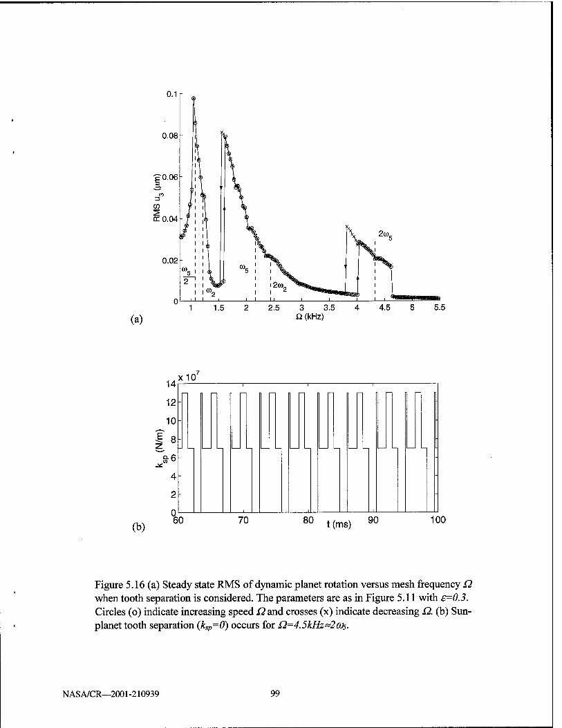
1 1.5
(a) 2.5 3 3.5
Q. (kHz)
(b)
14x 10' 14
12-
10-
8-
4-
2-
n _L
"
60 70 80 t(ms) 90 100
Figure 5.16 (a) Steady state RMS of dynamic planet rotation versus mesh frequency £2 when tooth separation is considered. The parameters are as in Figure 5.11 with e=0.3. Circles (o) indicate increasing speed Q and crosses (x) indicate decreasing Q. (b) Sun- planet tooth separation (ksp=0) occurs for Q=4.5kHz~2c05.
NASA/CR—2001-210939 99
CHAPTER 6
SUMMARY AND FUTURE WORK
6.1 Summary and Benefits
This work analytically investigates several key issues in planetary gear dynamics.
The main results and their benefits are summarized for each specific topic.
1. Dynamic Model of Planetary Gears
A lumped-parameter model is developed for spur planetary gears. Critical factors to
gear vibration are considered, including arbitrary planet spacing and phasing, gyroscopic
effects that are important in high-speed applications, mesh stiffness variation, and
transmission error excitation. The model is applicable to general epicyclic gears with
various configurations. It is suitable for the dynamic analysis of critical issues in
planetary gear vibration and useful for design guidance (response, natural frequencies,
etc.). This model is a key building block that can be expanded to couple with the housing
and include multiple stages.
2. Modal Properties
NASA/CR—2001-210939 101

This study characterizes the natural frequency spectrum and vibration mode
properties in planetary gears. Planetary gears possess rich modal structure that is crucial
for eigensensitivity, dynamic response, and stability analysis. Rigorous characterization
of these special properties is a fundamental advance for planetary gear vibration research.
These properties are capsulized as follows:
• When N planets are equally spaced, the vibration modes can be classified into six
rotational modes with distinct natural frequencies, six pairs of translational modes
with degenerate natural frequencies of multiplicity two, and three groups of planet
modes with degenerate natural frequencies of multiplicity N-3. Each type of vibration
mode has unique properties due to the cyclic symmetry of the system.
• When N/2 pairs of planets are diametrically opposed, the rotational and planet modes
have the same structure as for equally spaced planets; translational modes lose their
degeneracy but retain their distinct properties.
• When the planets are arbitrarily spaced, the rotational and translational modes
generally lose their well-defined structure; the remarkable properties of planet modes
are not affected by planet spacing.
3. Design Parameter Variations
The effects of design parameter variations on planetary gear free vibration are
analytically investigated. The sensitivities of natural frequencies and vibration modes to
key parameters are expressed in simple, closed-form formulae that allow one to quickly
identify the parameters that most impact the modal properties. Well-defined veering rules
are derived to examine the dramatic changes of vibration modes that are possible even for
NASA/CR—2001-210939 102

small parameter variations. These results rely on the structured vibration mode properties
characterized before. For design use, the results allow qualitative and quantitative
assessment of the effects of design parameters on planetary gear free vibration:
• Each of the sun-planet and ring-planet mesh stiffnesses affect one rotational mode,
one translational mode, and one planet mode.
• The transverse support stiffnesses and component masses of the carrier, ring, and sun
only affect translational modes.
• The torsional support stiffnesses and moments of inertia of the carrier, ring, and sun
only affect rotational modes.
• The planet bearing stiffness and inertia are critical parameters that affect most modes.
• The operating speed does not affect rotational and planet modes; translational mode
natural frequencies at zero speed split into distinct ones as speed increases.
4. Mesh Stiffness Variation Excitation
The parametric instabilities excited by mesh stiffness variations are investigated for
two-stage and planetary gear trains. The operating conditions leading to parametric
instabilities are analytically determined and numerically verified. The following findings
are obtained from this study.
• The contact ratios and mesh phasing strongly impact the instabilities induced by mesh
stiffness variation. Simple, exact formulae derived from perturbation analyses provide
design guidance to suppress particular instabilities by adjusting the contact ratios and
mesh phasing.
NASA/CR—2001-210939 103

• For two-stage gears in a countershaft configuration, the mesh excitations interact
when one mesh frequency is an integer multiple of the other and dramatically change
the instability conditions compared to two decoupled excitations.
• For planetary gears, the structured modal properties lead to vanishing of certain
instabilities, including the combination instability of distinct and degenerate natural
frequencies when planet meshes are in-phase, and the single-mode and combination
instabilities of distinct natural frequencies when planet meshes are sequentially
phased. Along with contact ratios, selection of planet phasing is an effective means to
avoid parametric instability and its associated large response.
6.2 Future Work
To thoroughly understand planetary gear dynamics and develop reliable design
tools for noise and vibration reduction, this research needs to be advanced in several
challenging areas discussed below.
1. Nonlinear Effects
Tooth separation nonlinearity strongly affects the dynamic behaviors of single-mesh
gears, including jump phenomena and multiple steady state solutions (Blankenship and
Kahraman 1995; Kahraman, 1992; Kahraman and Blankenship, 1996, 1997; Kahraman
and Singh, 1991; Parker et al., 2000b; Rook and Singh, 1995; Theodossiades and
Natsiavas, 2000). Typical methodologies such as direct integration, harmonic balance,
perturbation, and shooting method were used in the above analyses. This nonlinearity has
not been fully investigated in planetary gears. The contact loss nonlinearity, coupled with
NASA/CR—2001-210939 104

mesh stiffness variation, transmission error excitation, and mesh phasing, is expected to
impact dynamic responses, load sharing among planets, bearing loads, tooth fatigue, and
gear noise. Analytical study of nonlinear effects will provide improved design guidance
for planetary gears based on dynamic response.
2. Transmission Error Modeling
For single-mesh gears, static transmission error (STE) is naturally defined and
widely used as a metric for vibration and noise (Gregory et al., 1963-64; Smith, 1987;
Ozguven and Houser, 1988b). The specification of transmission errors in planetary gears
is complicated due to the carrier rotation and multiple meshes coupled together. Donley
and Steyer (1992) simply used a "net transmission error" that is the average of all
individual transmission errors of the sun-planet and ring-planet meshes. Although this
simplification reduces the computational and modeling effort, it is a significant
simplification difficult to interpret of the dynamic mesh forces. Other studies (Kahraman,
1994b, 1999; Kahraman and Blankenship, 1994) used Fourier series to represent STE in
each mesh, but did not address the physical modeling related to profile error, pitch error,
run-out error, and misalignment. It remains a question how to synthesize transmission
errors from these parameters in planetary gears. More investigations are needed to define,
calculate, and measure a useful analog of STE in planetary gears.
3. Dynamic Response
Dynamic response from analytical models is useful to predict the noise and
vibration early in the design stage. To reliably determine dynamic response, it requires
precise representation of dynamic excitation from tooth meshes. The time-varying mesh
NASA/CR—2001-210939 105

stiffness and transmission error for single-mesh gears can be calculated from the contact
analysis program LDP (Houser, 1990) or other tools. A major challenge is to match
dynamic response obtained from analytical models using these approximations as input
with benchmark computational and experimental results. No such comparison exists for
planetary gears, and this restricts the application of analytical models in practical design.
In addition, the effects of major design factors (e.g., contact ratio, mesh phasing, mesh
stiffness variation, support/bearing stiffness, tooth modification) on dynamic response
need be characterized for design guidance. This investigation will start with two-stage
spur gears and then extend to more complicated planetary gears.
4. Ring Gear Flexibility
The ring body is considered rigid in this dissertation. In practice, internal gears with
thin rims may distort elastically. Experimental measurements (Ma and Botman, 1984)
and finite element computations (Kahraman and Vijayakar, 2000) have shown dramatic
changes in load sharing among planets from the ring flexibility. Because the ring is
usually connected to the housing, its flexibility directly influences the transmission of
structure-borne noise. The elastic distortion of the ring can also affect the mesh
stiffnesses and lead to contact loss. Qualitative and quantitative analyses of the effects of
ring flexibility is necessary to improve understanding of physical behaviors. The
fundamental task is to extend the current discrete model by including the continuous
deformation of the ring body. The analytical and computational methods discussed in
this work can likely be used on this extended model.
5. Experimental Verification
NASA/CR—2001-210939 106

5. Experimental Verification
The inherent complexity of gear dynamics requires experimental validation of
analytical and numerical results. For single-mesh gear models, there are extensive
experiments verifying analytical findings as well as presenting questions for research and
design. The analytical models of planetary gears, however, have not been properly
validated because of the lack of benchmark experimentation. The calculated vibrations
from the finite element tool Calyx agree well with measured results at NASA Glenn
Research Center (Krantz, 1992) and General Motors (Blankenship and Kahraman, 1996;
Kahraman and Blankenship, 1997, 1999a, b; Parker et al., 2000b). More experimental
studies are needed to develop reliable dynamic models suitable for practical design and
investigate critical issues in planetary gear vibration.
NASA/CR—2001-210939 107
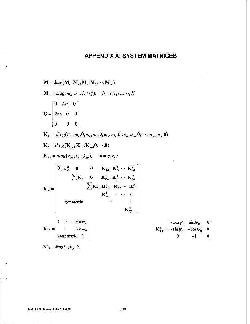
APPENDIX A: SYSTEM MATRICES
M = diag(Mc,Mr,Ms,M1,~;MN)
Mh = diag(mh ,mhJhl r;,2), h = c, r, s,\, — ,N
G =
Kci=diag(mc,mc,0,mr,mr,0,ms,ms,0,mp,mp,0,---,mp,mp,0)
Kb=diag(Kcb,Krb,Ksb,0,-,0)
Khb= diagik^, khy ,khll), h = c, r, s
0 - 2mh 0"
2m * o 0
0 0 0
"I K2, o 0 Kc2 Kc2 ' "• ^c2
ZK"i o Kr2 Kr2 ■ " *-r2
K„, - IX", K*2 K*2 •" *-*2
KPP 0 •• 0
symmetric
1 0 - sin y/n
Kei = 1 cos ysn
symmetric 1
K» _ c2 ~
■cosy/n sin^„ 0
■sm.y/n -cos^„ 0
0-10
K.n^=diag{kpnkpnp)
NASA/CR—2001-210939 109
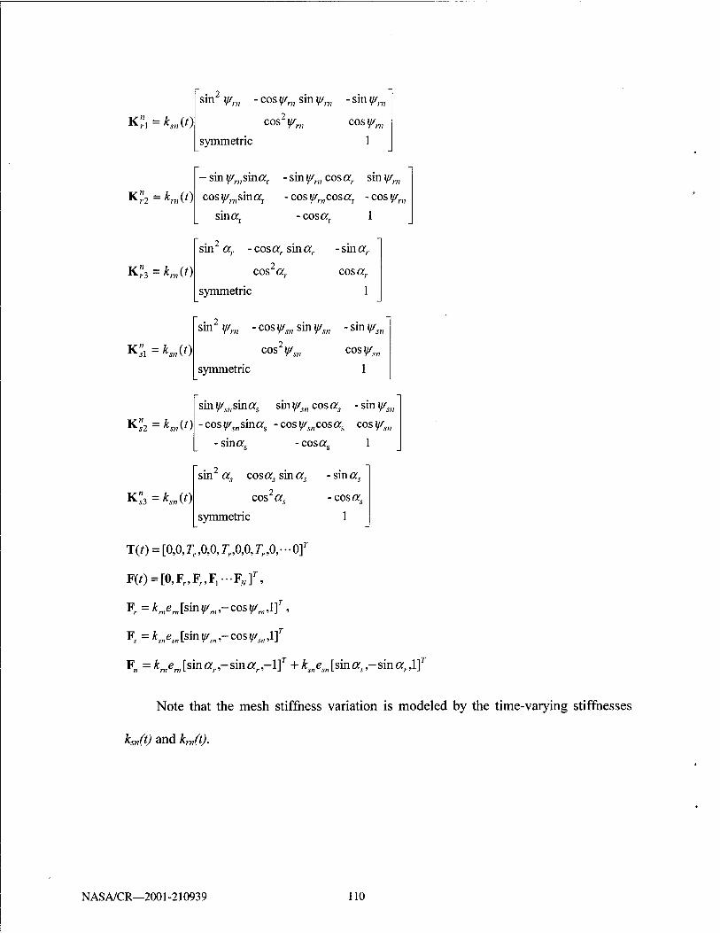
K?! =*,„(/)
rn sin2 y/m - cos y/m sin ^„, - sin y,
cosV™ cos^„, symmetric 1
Ki=KM) - sm fmsinar - sm y/rn cos or,, sm y/n,
cos ^,.„sinorr - cos y/ri1cosar - cos ^ra
sin a; -cosorr 1
K,"3 =*„,(>)
sin or,, -cos or,, sin or,. -smor,.
cos2 or,. cos or,.
symmetric
K?! =*,„(')
sin2 yfn - cosy/sn sin ^„ - sin y/s
cosV« cos^,,
*^J2 — *«?(0
K?3 = *,„(')
symmetric 1
sin^„sinors sin^cosor, -sin^,„
-cos^„sinors -cos^„cosors cos^„
■sinorc ■cosor 1
sm or, cos or, sin or, -sinor,
cos2 or, - cos a,
symmetric 1
T(t) = [o,ojc,o,o,Tr,o,ojr,o,--o]T
F(0 = [0,Fr,F„F1-FJV]r
>
Fr=*mem[sin^BI,-cosi/m,l]r,
F=^esn[sin^„,-cos^„,lf
F„ = Ken, tsin a, - sin «, -l]r + ^e™ tsin «, ~ sin «,>!f
Note that the mesh stiffness variation is modeled by the time-varying stiffnesses
ks„(t) and km(t).
N AS A/CR—2001 -210939 110

APPENDIX B: EXAMPLE SYSTEM
The planetary gear used in the U.S. Army's Helicopter OH-58 is the benchmark
example in the work. Two cases of the system are used in the study.
Case I: The ring gear is free and the system has 3(N+3) degree of freedom, where N is
the number of planets. The model parameters are given in Table C.l.
Case II: The ring gear is fixed (kr= kru- 0) and other parameters are the same as Table
C.l. The system has four planets and 18 degrees of freedom.
Sun Ring Carrier Planet
Mass (kg) 0.4 2.35 5.43 0.66
I/r'Ckg) 0.39 3.00 6.29 0.61
Base diameter (mm) 77.42 275.03 177.8 100.35
Teeth number 27 99 35
Mesh stiffness (N/m) Ksp Kfjt Km jXl v
Bearing stiffness (N/m) l\n K$ l\y Kg 1 \J
Torsional stiffness (N/m) Knl —IV fCsli— Kcu — V
Pressure angle (°) <% = <Xr = a = 24.6
Table B.l Model parameters of the planetary gear in the U.S. Army's helicopter OH-58
NASA/CR—2001-210939 111

BIBLIOGRAPHY
1. Adelman, H.M. and Haftka, R.T., 1986, Sensitivity Analysis of Discrete Structural Systems, AIAA Journal, 24(5): 823-832.
2. Agashe, V., 1998, Computational Analysis of the Dynamic Response of a Planetary Gear System, Master Thesis, Ohio State University.
3. Amabili, M. and Rivola, A., 1997, Dynamic Analysis of Spur Gear Pairs: Steady-State Response and Stability of the SDOF Model with Time-Varying Meshing Damping, Mechanical Systems and Signal Processing, 11(3): 375-390.
4. Arakere, N.K. and Nataraj, C, 1999, Numerical Simulation of Nonlinear Spur Gear Dynamics, ASME Design Engineering Technical Conferences, DETC99/VJJB-8110, September, Las Vegas, NV.
5. August, R., 1983, Dynamics of Planetary Gear Trains, Ph. D. Thesis, Cleveland State University.
6. August, R. and Kasuba, R, 1986, Torsional Vibrations and Dynamic Loads in a Basic Planetary Gear System, Journal of Vibration, Acoustics, Stress, and Reliability in Design, 108(3): 348-353.
7. Benton, M. and Seireg, A., 1978, Simulation of Resonances and Instability Conditions in Pinion-Gear Systems, ASME Journal of Mechanical Design, 100: 26-30.
8. Benton, M. and Seireg, A., 1980a, Application of the Ritz Averaging Method to Determining the Response of Systems with Time Varying Stiffness to Harmonic Excitation, ASME Journal of Mechanical Design, 102(2): 384-390.
9. Benton, M. and Seireg, A., 1980b, Normal Mode Uncoupling of Systems with Time Varying Stiffness, ASME Journal of Mechanical Design, 102(2): 379-383.
10. Benton, M. and Seireg, A., 1981, Factors Influencing Instability and Resonances in Geared Systems, ASME Journal of Mechanical Design, 103(2): 372-378.
11. Bernard, M.L. and Bronowicki, A.J., 1994, Modal Expansion Method for Eigensensitivity with Repeated Roots, AIAA Journal, 32(7): 1500-1506.
12. Blankenship, G.W. and Kahraman, A., 1995, Steady State Forced Response of a Mechanical Oscillator with Combined Parametric Excitation and Clearance Type Non-Linearity, Journal of Sound and Vibration, 185(5): 743-765.
13. Blankenship, G.W. and Kahraman, A., 1996, Gear Dynamics Experiments, Part I: Characterization of Forced Response, Proceedings of the 1996 Power Transmission and Gearing Conference, 373-380.
NASA/CR—2001-210939 113

14. Blankenship, G.W. and Singh, R., 1995, Analytical Solution for Modulation Side-Band Associated with a Class of Mechanical Oscillators, Journal of Sound and Vibration, 179(1): 13-36.
15. Bollinger, J.G. and Harker, R.J., 1967, Instability Potential of High Speed Gearing, Journal of the Industrial Mathematics, 17: 39-55.
16. Bolotin, V.V., 1964, The Dynamic Stability of Elastic Systems, Holden-Day, San Francisco.
17. Botman, M., 1976, Epicyclic Gear Vibrations, Journal of Engineering for Industry, 96: 811- 815.
18. Botman, M., 1980, Vibration Measurements on Planetary Gears of Aircraft Turbine Engines, AIAA Journal, 17:351-357.
19. Butcher, E.A. and Sinha, S.C., 1996, Hybrid Formulation for the Analysis of Time-Periodic Linear Systems Via Chebyshev Polynomials, Journal of Sound and Vibration, 195(3): 518- 527.
20. Chen, P. and Ginsberg, J.H., 1992, On the Relationship between Veering of Eigenvalue Loci and Parameter Sensitivity of Eigenfunctions, Journal of Vibration and Acoustics, 114: 141- 148.
21. Chiang, T. and Badgley, R.H., 1973, Reduction of Vibration and Noise Generated by Planetary Ring Gears in Helicopter Aircraft Transmission, Journal of Engineering for Industry, 93: 1149-1158.
22. Cornwell, P.J. and Bendiksen, O.O., 1992, Numerical Study of Vibration Localization in Disordered Cyclic Structures, AIAA Journal, 30(2): 473-481.
23. Courant, R. and Hubert, D., 1989, Methods of Mathematical Physics, John Wiley & Sons, New York.
24. Cunliffe, F., Smith, J.D. and Welbourn, D.B., 1974, Dynamic Tooth Loads in Epicyclic Gears, Journal of Engineering for Industry, 94: 578-584.
25. Dailey, R.L., 1989, Eigenvector Derivatives with Repeated Eigenvalues, AIAA Journal, 27(4): 486-491.
26. Donley, M.G. and Steyer, G.C., 1992, Dynamic Analysis of a Planetary Gear System, Proc. of the 1992 International Power Transmission and Gearing Conference, 117-127.
27. Fox, R.L. and Kapoor, M.P., 1968, Rates of Change of Eigenvalues and Eigenvectors, AIAA Journal, 6: 2426-2429.
28. Frater, J.L., August, R. and Oswald, F.B., 1983, Vibration in Planetary Gear Systems with Unequal Planet Stiffnesses, NASA Technical Memorandum 83428.
29. Friswell, M.I., 1996, The Derivatives of Repeated Eigenvalues and Their Associated Eigenvectors, Journal of Vibration and Acoustics, 118: 390-397.
30. Gregory, R.W. et al., 1963-64, Dynamic Behavior of Spur Gears, Proceedings of Institute of Mechanical Engineers, 178(8): 207-226.
31. Happawana, G.S., Bajaj, A.K. and Nwokah, O.D.I., 1991, Singular Perturbation Perspective on Mode Localization, Journal of Sound and Vibration, 147(2): 361-365.
NASA/CR—2001-210939 114
32. Happawana, G.S., Bajaj, A.K. and Nwokah, O.D.I., 1993, Singular Perturbation Analysis of Eigenvalue Veering and Modal Sensitivity in Perturbed Linear Periodic Systems, Journal of Sound and Vibration, 160(2): 225-242.
33. Happawana, G.S., Nwokah, O.D.I., Bajaj, A.K. and Azene, M., 1998, Free and Forced Response of Mistuned Linear Cyclic Systems: A Singular Perturbation Approach, Journal of Sound and Vibration, 211: 761-789.
34. Heath, G. and Bossler, R., 1993, Advanced Rotorcraft Transmission (Art) Program-Final Report, NASA CR-191057, ARL-CR 14.
35. Hidaka, T., Terauchi, Y. and Nagamura, K., 1976a, Dynamic Behavior of Planetary Gears - 1st Report: Load Distribution, Bull. JSME, 19(132): 690-698.
36. Hidaka, T., Terauchi, Y. and Ishioka, K., 1976b, Dynamic Behavior of Planetary Gear -2nd Report, Displacement of Sun Gear and Ring Gear, Bulletin of the JSME, 19(138): 1563- 1570.
37. Hidaka, T., et al., 1977, Dynamic Behavior of Planetary Gear-3rd Report, Displacement of Ring Gear in Direction of Line of Action, Bulletin of the JSME, 20: 1663-1672.
38. Hidaka, T., Terauchi, Y. and Ishioka, K., 1979a, Dynamic Behavior of Planetary Gear-4th Report, Influence of the Transmitted Tooth Load on the Dynamic Increment Load, Bulletin of the JSME, 22(168): 877-884.
39. Hidaka, T., Terauchi, Y. and Nagamura, K., 1979b, Dynamic Behavior of Planetary Gear - 5th Report, Dynamic Increment of Torque, Bulletin of the JSME, 22(169): 1017-1025.
40. Hidaka, T., Terauchi, Y. and Nagamura, K., 1979c, Dynamic Behavior of Planetary Gear - 6th Report, Influence of Meshing-Phase, Bulletin of the JSME, 22(169): 1026-1033.
41. Hidaka, T., Terauchi, Y. and Nagamura, K., 1979d, Dynamic Behavior of Planetary Gear - 7th Report, Influence of the Thickness of the Ring Gear, Bulletin of the JSME, 22(170): 1142-1149.
42. Hidaka, T., Terauchi, Y. and Dohi, K., 1979e, On the Relation between the Run-out Errors and the Motion of the Center of Sun Gear in a Stoeckicht Planetary Gear, Bulletin of the JSME, 22(167): 748-754.
43. Hidaka, T., Terauchi, Y. and Fujii, M., 1980, Analysis of Dynamic Tooth Load on Planetary Gear, Bulletin of the JSME, 23(176): 315-323.
44. Hidaka, T., Sugimoto, N. and Ishida, T., 1986, Effects of Errors of Elements on Load Distribution in Planetary Gears with Various Load Equalizing Mechanisms, 52(480): 2200- 2206.
45. Hidaka, T., Ishida, T., Wang, K.-j. and Emoto, M., 1993, Vibration of Solar-Type Planetary Gears, Transactions of the Japan Society of Mechanical Engineers, Part C, 59(567): 3548- 3554.
46. Houser, D. R., 1990, Gear Noise Sources and Their Prediction Using Mathematical Models, Gear Design Manufacturing and Inspection Manual, Chapter 16, SAE.
47. Hsu, C.S., 1963, On the Parametric Excitation of a Dynamic System Having Multiple Degrees of Freedom, Journal of Applied Mechanics, 30: 367-372.
NASA/CR—2001-210939 115

48. Hsu, C.S., 1965, Further Results on Parametric Excitation of a Dynamic System, Journal of Applied Mechanics, 32: 373-377.
49. Hsu, C.S. and Cheng, W.H., 1974, Steady-State Response of a Dynamical System under Combined Parametric and Forcing Excitations, Journal of Applied Mechanics, 41: 371-378.
50. Ibrahim, R.A. and Barr, A.D.S., 1978, Parametric Vibration Part-I: Mechanics of Linear Problems, Shock and Vibration Digest, 10: 15-29.
51. Kahraman, A., 1992, On the Response of a Preloaded Mechanical Oscillator With a Clearance: Period-Doubling and Chaos, Nonlinear Dynamics, 3: 183-198.
52. Kahraman, A., 1994a, Load Sharing Characteristics of Planetary Transmissions, Mechanism and Machine Theory, 29: 1151-1165.
53. Kahraman, A., 1994b, Planetary Gear Train Dynamics, ASME Journal of Mechanical Design, 116(3): 713-720.
54. Kahraman, A., 1994c, Natural Modes of Planetary Gear Trains, Journal of Sound and Vibration, 173(1): 125-130.
55. Kahraman, A., 1994d, Dynamic Analysis of a Multi-Mesh Helical Gear Train, ASME Journal of Mechanical Design, 116(3): 706-712.
56. Kahraman, A., 1999, Static Load Sharing Characteristics of Transmission Planetary Gear Sets: Model and Experiment, Transmission and Driveline Systems Symposium, SAE paper 1999-01-1050.
57. Kahraman, A. and Blankenship, G.W., 1994, Planet Mesh Phasing in Epicyclic Gear Sets, Proc. of International Gearing Conference, Newcastle, UK, 99-104.
58. Kahraman, A. and Blankenship, G.W., 1996, Interactions between Commensurate Parametric and Forcing Excitations in a System with Clearance, Journal of Sound and Vibration, 194(3): 317-336.
59. Kahraman, A. and Blankenship, G.W., 1997, Experiments on Nonlinear Dynamic Behavior of an Oscillator with Clearance and Periodically Time-Varying Parameters, Journal of Applied Mechanics, 64: 217-226.
60. Kahraman, A. and Blankenship, G.W., 1999a, Effect of Involute Contact Ratio on Spur Gear Dynamics, ASME Journal of Mechanical Design, 121(1): 112-118.
61. Kahraman, A. and Blankenship, G.W., 1999b, Effect of Involute Tip Relief on Dynamic Response of Spur Gear Pairs, ASME Journal of Mechanical Design, 121(2): 313-315.
62. Kahraman, A. and Singh, R., 1991, Nonlinear Dynamics of a Geared Rotor-Bearing System with Multiple Clearances, Journal of Sound and Vibration, 144(3): 469-506.
63. Kahraman, A. and Vijayakar, S.M., 2000, Effect of Internal Flexibility on the Quasi-Static Behavior of a Planetary Gear Set, ASME Design Engineering Technical Conferences, Paper No. DETC2000/PTG-14364, September, Baltimore, MD.
64. Kasuba, R. and August, R., 1984, Gear Mesh Stiffness and Load Sharing in Planetary Gearing, ASME 4th Power Transmission Conference, ASME Paper 84-DET-229, Cambridge, MA.
NASA/CR—2001-210939 116

65. Kasuba, R. and Evans, J.W., 1981, An Extended Model for Determining Dynamic Loads in Spur Gearing, ASME Journal of Mechanical Design, 103: 398-409.
66. Krantz, T.L., 1992, Gear Tooth Stress Measurements of Two Helicopter Planetary Stages, NASA Technical Memorandum 105651.
67. Krantz, T. L., 1993, Mechanical Systems Technology Branch Research Summary, 1985- 1992, NASA Technical Memorandum 106329.
68. Kryloff, N. and Bogoliuboff, N., 1947, Introduction to Non-Linear Mechanics, Princeton university press, Princeton.
69. Leissa, A.W., 1974, On a Curve Veering Aberration, Journal of Applied Mathematics and Physics, 25: 99-112.
70. Lim, T.C. and Li, J., 1999, Dynamic Analysis of Multi-Mesh Counter-Shaft Transmission, Journal of Sound and Vibration, 219: 905-919.
71. Lin, H.H., Townsend, D.P. and Oswald, F.B., 1993, Prediction of Gear Dynamics Using Fast Fourier-Transform of Static Transmission Error, Mechanics Of Structures And Machines, 21(2): 237-260.
72. Lin, J. and Parker, R.G., 1999a, Analytical Characterization of the Unique Properties of Planetary Gear Free Vibration, Journal of Vibration and Acoustics, 121: 316-321.
73. Lin, J. and Parker, R.G., 1999b, Sensitivity of Planetary Gear Natural Frequencies and Vibration Modes to Model Parameters, Journal of Sound and Vibration, 228(1): 109-128.
74. Lin, J. and Parker, R.G., 2000a, Structured Vibration Characteristics of Planetary Gears with Unequally Spaced Planets, Journal of Sound and Vibration, 233(5): 921-928.
75. Lin, J. and Parker, R.G., 2000b, Natural Frequency Veering in Planetary Gears under Design Parameter Variations, Mechanics of Structures and Machines, submitted.
76. Lin, J. and Parker, R.G., 2000c, Mesh Stiffness Variation Instabilities in Two-Stage Gear Systems, Journal of Vibration and Acoustics, submitted.
77. Lin, J. and Parker, R.G., 2000d, Parametric Instabilities in Planetary Gears under Mesh Stiffness Variations, Journal of Vibration and Acoustics, in preparation.
78. Lindh, K. G. and Likins, P. W., 1970, Infinite Determinant Methods for Stability Analysis of Periodic-Coefficient Differential Equations, ALAA Journal, 8: 680-686.
79. Liu, H.-J. and Zhao, L.-C, 1997, Mode Localization Due to Asymmetric Structural Changes, Computers and Structures, 65(1): 91-96.
80. Lynwander, P., 1983, Gear Drive Systems: Design and Application, Dekker, New York.
81. Ma, P. and Botman, M., 1984, Load Sharing in a Planetary Gear Stage in the Presence of Gear Errors and Misalignment, Journal of Mechanisms, Transmissions and Automation in Design, 104: 1-7.
82. McLachlan, N.W., 1947, Theory and Application of Mathieu Functions, Clarendon Press, Oxford.
83. Meirovitch, L., 1967, Analytical Methods in Vibration, Macmillan, New York.
NASA/CR—2001-210939 117

84. Mills-Curran, W.C., 1988, Calculation of Eigenvector Derivatives for Structures with Repeated Eigenvalues, AIAA Journal, 26(7): 867-871.
85. Müller, H.W., 1982, Epicyclic Drive Trains: Analysis, Synthesis, and Applications, Wayne State University Press, Detroit.
86. Nataraj, C. and Arakere, N.K., 1999, Dynamic Response and Stability of a Spur Gear Pair, ASME Design Engineering Technical Conferences, DETC99/VTB-8110, Las Vegas, NV.
87. Nataraj, C. and Whitman, A.M., 1997, Parameter Excitation Effects in Gear Dynamics, ASME Design Engineering Technical Conferences, DETC97/VTB-4018, Sacramento, CA.
88. Nayfeh, A.H., 1973, Perturbation Methods, John Wiley & Sons, New York.
89. Nayfeh, A.H. and Mook, D.T., 1979, Nonlinear Oscillations, Wiley-Interscience.
90. Noah, S.T. and Hopkins, G.R., 1982, Generalized Hill's Method for the Stability Analysis of Parametrically Excited Dynamic Systems, ASME Journal of Applied Mechanics, 49(1): 217-223.
91. Ozguven, H.N. and Houser, D.R., 1988a, Dynamic Analysis of High-Speed Gears by Using Loaded Static Transmission Error, Journal of Sound and Vibration, 125(1): 71-83.
92. Ozguven, H.N. and Houser, D.R., 1988b, Mathematical-Models Used in Gear Dynamics - a Review, Journal of Sound and Vibration, 121(3): 383-411.
93. Parker, R.G., 2000, A Physical Explanation for the Effectiveness of Planet Phasing to Suppress Planetary Gear Vibration, Journal of Sound and Vibration, 236(4): 561-573.
94. Parker, R.G., Agashe, V. and Vijayakar, S.M., 2000a, Dynamic Response of a Planetary Gear System Using a Finite Element/Contact Mechanics Model, ASME Journal of Mechanical Design, 122(3): 305-311.
95. Parker, R.G., Vijayakar, S.M. and Imajo, T., 2000b, Nonlinear Dynamic Response of a Spur Gear Pair: Modeling and Experimental Comparisons, Journal of Sound and Vibration, 236(4):561-573.
96. Perkins, N.C. and Mote, CD., Jr., 1986, Comments on Curve Veering in Eigenvalue Problems, Journal of Sound Vibration, 106: 451-463.
97. Pierre, C, 1988, Mode Localization and Eigenvalue Loci Veering Phenomena in Disordered Structures, Journal of Sound Vibration, 126(3): 485-502.
98. Pierre, C. and Murthy, D.V., 1992, Aeroelastic Modal Characteristics of Mistuned Blade Assemblies: Mode Localization and Loss of Eigenstructure, AIAA Journal, 30: 2483-2496.
99. Pintz, A. and Kasuba, R., 1985, Dynamic Load Factors in Internal Spur Gear Drives, Journal of Mechanisms, Transmissions, and Automation in Design, 107: 424-429.
100. Raclot, J. P. and Velex, P., 1999, Simulation of the Dynamic Behavior of Single and Multi- stage Geared Systems with Shape Deviations and Mounting Errors by Using a Spectral Method, Journal of Sound and Vibration, 220: 861-903.
101. Rakhit, A.K., 1997, Improved Epicyclic Gearbox for Reduced and Controllable Subsynchronous Vibrations in Gas Turbogenerator Applications, Journal of Engineering for Gas Turbines and Power, 119(3): 640-646.
NASA/CR—2001-210939 118
102. Ramamurti, V. and Seshu, P., 1990, On the Principle of Cyclic Symmetry in Machine Dynamics, Communications in Applied Numerical Methods, 6(4): 259-268.
103. Rook, T.E. and Singh, R., 1995, Dynamic Analysis of a Reverse-Idler Gear Pair with Concurrent Clearances, Journal of Sound Vibration, 182(2): 303-322.
104. Saada, A. and Velex, P., 1995, An Extended Model for the Analysis of the Dynamics of Planetary Trains, ASME Journal of Mechanical Design, 117: 241-247.
105. Seager, D.L., 1975, Conditions for the Neutralization of Excitation by the Teeth in Epicyclic Gearing, Journal of Mechanical Engineering Science, 17: 293-298.
106. Sinha, S.C., Pandiyan, R. and Bibb, J.S., 1996, Liapunov-Floquet Transformation: Computation and Applications to Periodic Systems, Journal of Vibration and Acoustics, 118:209-219.
107. Sinha, S.C. and Wu, D.-H., 1991, Efficient Computational Scheme for the Analysis of Periodic Systems, Journal of Sound and Vibration, 151(1): 91-117.
108. Smith, J.D., 1983, Gears and Their Vibration: A Basic Approach to Understanding Gear Noise, Macmillan Press, New York.
109. Smith, R.E., 1987, The Relationship of Measured Gear Noise to Measured Gear Transmission Errors, AGMA 87FTM6, Cincinnati.
110. Struble, R.A., 1962, Nonlinear Differential Equations, McGraw-Hill, New York.
111. Theodossiades, S. and Natsiavas, S., 2000, Non-Linear Dynamics of Gear-Pair Systems with Periodic Stiffness and Backlash, Journal of Sound and Vibration, 229(2): 287-310.
112. Toda, A. and Botman, M., 1979. Planet Indexing in Planetary Gears for Minimum Vibration, ASME Design Engineering Technical Conference, St. Louis.
113. Tordion, G.V. and Gauvin, R., 1977, Dynamic Stability of a Two-Stage Gear Train under the Influence of Variable Meshing Stiffnesses, Journal of Engineering for Industry, 99: 785- 791.
114. Velex, P. and Flamand, L., 1996, Dynamic Response of Planetary Trains to Mesh Parametric Excitations, ASME Journal of Mechanical Design, 118: 7-14.
115. Vijayakar, S.M., 1991, A Combined Surface Integral and Finite Element Solution for a Three-Dimensional Contact Problem, International Journal for Numerical Methods in Engineering, 31: 524-546.
116. Vinayak, H., Singh, R. and Padmanabhan, C, 1995, Linear Dynamic Analysis of Multi- Mesh Transmissions Containing External, Rigid Gears, Journal of Sound and Vibration, 185(1): 1-32.
117. Wei, S.-T. and Pierre, C, 1988a, Localization Phenomena in Mistuned Assemblies with Cyclic Symmetry, Part I: Free Vibrations, Journal of Vibration, Acoustics, Stress and Reliability in Design, 110(4): 429-438.
118. Wei, S.-T. and Pierre, C, 1988b, Localization Phenomena in Mistuned Assemblies with Cyclic Symmetry, Part II: Forced Vibrations, Journal of Vibration, Acoustics, Stress and Reliability in Design, 110(4): 439-449.
NASA/CR—2001-210939 119

REPORT DOCUMENTATION PAGE Form Approved
OMB No. 0704-0188
Public reporting burden for this collection of information is estimated to average 1 hour per response, including the time for reviewing instructions, searching existing data sources, gathering and maintaining the data needed, and completing and reviewing the collection of information. Send comments regarding this burden estimate or any other aspect of this collection of information, including suggestions for reducing this burden, to Washington Headquarters Services, Directorate for Information Operations and Reports, 1215 Jefferson Davis Highway, Suite 1204, Arlington, VA 22202-4302, and to the Office of Management and Budget, Paperwork Reduction Project (0704-0188), Washington, DC 20503.
1. AGENCY USE ONLY (Leave blank) REPORT DATE
May 2001 3. REPORT TYPE AND DATES COVERED
Final Contractor Report 4. TITLE AND SUBTITLE
Modeling, Modal Properties, and Mesh Stiffness Variation Instabilities of Planetary Gears
6. AUTHOR(S)
Robert G. Parker and Jian Lin
5. FUNDING NUMBERS
WU-712-20-13-00 NAG3-1979 1L161102AH45
7. PERFORMING ORGANIZATION NAME(S) AND ADDRESS(ES)
Ohio State University Department of Mechanical Engineering 206 West 18th Avenue Columbus, Ohio 43210-1107
8. PERFORMING ORGANIZATION REPORT NUMBER
E-12792
SPONSORING/MONITORING AGENCY NAME(S) AND ADDRESS(ES)
National Aeronautics and Space Administration Washington, DC 20546-0001 and U.S. Army Research Laboratory Adelphi, Maryland 20783-1145
10. SPONSORING/MONITORING AGENCY REPORT NUMBER
NASA CR—2001-210939 ARL-CR-462
11. SUPPLEMENTARY NOTES
Project Manager, Timothy L. Krantz, Structures and Acoustics Division, NASA Glenn Research Center, organization code 5950, 216-433-3580.
12a. DISTRIBUTION/AVAILABILITY STATEMENT
Unclassified - Unlimited Subject Categories: 37 and 07 Distribution: Nonstandard
Available electronically at http://gltrs.grc.nasa.gov/GLTRS
This publication is available from the NASA Center for AeroSpace Information. 301-621-0390.
12b. DISTRIBUTION CODE
13. ABSTRACT (Maximum 200 words) Planetary gear noise and vibration are primary concerns in their applications in helicopters, automobiles, aircraft engines, heavy machinery and marine vehicles. Dynamic analysis is essential to the noise and vibration reduction. This work analytically investigates some critical issues and advances the understanding of planetary gear dynamics. A lumped-parameter model is built for the dynamic analysis of general planetary gears. The unique properties of the natural frequency spectra and vibration modes are rigorously characterized. These special structures apply for general planetary gears with cyclic symmetry and, in practically important case, systems with diametrically opposed planets. The special vibration properties are useful for subsequent research. Taking advantage of the derived modal properties, the natural frequency and vibration mode sensitivities to design parameters are investigated. The key parameters include mesh stiffnesses, support/bearing stiffnesses, component masses, moments of inertia, and operating speed. The eigen- sensitivities are expressed in simple, closed-form formulae associated with modal strain and kinetic energies. As disorders (e.g., mesh stiffness variation, manufacturing and assembling errors) disturb the cyclic symmetry of planetary gears, their effects on the free vibration properties are quantitatively examined. Well-defined veering rules are derived to identify dramatic changes of natural frequencies and vibration modes under parameter variations. The knowledge of free vibration properties, eigensensitivities. and veering rules provide important information to effectively tune the natural frequencies and optimize structural design to minimize noise and vibration. Parametric instabilities excited by mesh stiffness variations are analytically studied for multi- mesh gear systems. The discrepancies of previous studies on parametric instability of two-stage gear chains are clarified using perturbation and numerical methods. The operating conditions causing parametric instabilities are expressed in closed-form suitable for design guidance. Using the well-defined modal properties of planetary gears, the effects of mesh parameters on parametric instability are analytically identified. Simple formulae are obtained to suppress particular instabilities by adjusting contact ratios and mesh phasing.
14. SUBJECT TERMS
Gear; Transmissions; Dynamic stability; Eigenvalues
15. NUMBER OF PAGES 123
16. PRICE CODE
17. SECURITY CLASSIFICATION OF REPORT
Unclassified
18. SECURITY CLASSIFICATION OF THIS PAGE
Unclassified
19. SECURITY CLASSIFICATION OF ABSTRACT
Unclassified
20. LIMITATION OF ABSTRACT
NSN 7540-01-280-5500 Standard Form 298 (Rev. 2-89) Prescribed by ANSI Std. Z39-18 298-102