Embed Size (px)
Citation preview
Hindawi Publishing CorporationISRN Applied MathematicsVolume 2013 Article ID 981692 8 pageshttpdxdoiorg1011552013981692
Research ArticleNonlinear Second-Order Model and Equilibrium PointCharacteristic Analysis of DC Traction Power Supply System
Y H Li1 X J Tian1 and X Q Li2
1 School of Automation Science and Electrical Engineering Beihang University Beijing 100191 China2 College of Information Engineering Beijing Institute of Petrochemical Technology Beijing 102617 China
Correspondence should be addressed to X Q Li lixiaqingbipteducn
Received 21 April 2013 Accepted 9 June 2013
Academic Editors E Kita and H-T Yau
Copyright copy 2013 Y H Li et al This is an open access article distributed under the Creative Commons Attribution License whichpermits unrestricted use distribution and reproduction in any medium provided the original work is properly cited
According to the different features of the DC traction network transient current in the Metro the electromagnetic transientprocess of traction power supply system that should be divided into the two forms of short-circuit fault and the low-frequencyoscillation was proposed While traction network short-circuit fault happens the system model is a weakly nonlinear first-orderdifferential equation which feeder current is increasing exponentially and eventually stabilized While the load current becomeslow-frequency oscillation current the system model is a nonlinear second-order differential equation After linear processingin unique equilibrium point neighborhood the state space equation of linear system is built and the structural reason of low-frequency oscillation is revealed by eigenvalue analysis methodThe simulation result shows that the simulation current waveformsare consistent with the recorded current waveforms and the division of transient process is reasonable
1 Introduction
Metro becomes the favor of big cities in the world because ofits transport features of rapid larger capacity three dimen-sions and environment protection effect of green pollution-free [1] Because Metro vehicle adopts electric tractiontheir safe operation state depends on stability of the DCtraction power supply system (TPSS) and its fault protectionmeasures Traditionally the main factor which influencesMetro operation safety is the traction network short-circuitfault of high incidence and heavy harmfulness Howeverwith the continuous increase of transport capacity and theextensive application of regenerative braking technology thelow-frequency oscillation current of high incidence appearsin traction network which has the characteristic of fasterstart up and short duration and is not characterized as faultHowever as the similarity of divergent oscillation currentand remote short-circuit fault current in the amplitude andslope feature the protection device often regards oscillationcurrent as fault current and causes the protection systemmalfunction Both determination of traction network faulttype and reveal of oscillation generation mechanism rely onthe analysis of electromagnetic transient process of TPSS
thus it is very significance to establish accurately systemmodel and study its stability for Metro operation safety
While the traction network short-circuit fault happensthe electromagnetic transient model of TPSS is presently thezero-state response of first-order RL series circuit [2] whosecorrespondingmain protection algorithm is the combinationalgorithm of 119889119894119889119905 minus Δ119894 (current rate-current increment)[3 4] thereby the feeder current increases by index lawand reaches eventually a stable status during the tractionnetwork short-circuit fault Against the fact that there existoscillation phenomenon in the transient current of tractionnetwork the transient model considering AC side of powersupply effect to short-circuit current waveform is presentedin [5] and the simulation waveform with ldquoovershootrdquo phe-nomenon and the important conclusion of positive correla-tion between overshoot degree and fault distance are gotThetransient physical model of TPSS that is a second-order RLhybrid circuit is presented in [6] the short-circuit currentis provided from many nearby substations and the sameconclusion is concluded However it can be learned fromactual recorded current waveform of Beijing Metro that theoscillation phenomenon does not appear in feeder currentduring short-circuit fault of traction network while the
2 ISRN Applied Mathematics
0 20 40 60 80 100 120 140 160 180 200
00
20
40
60
80
100
120
Curr
ent (
kA)
minus20
Time (ms)
(a) Short-circuit fault current
Time (ms)0 50 100 150 200 250 300 350 400
00
10
20
30
40
50
minus10
Curr
ent (
kA)
(b) Low-frequency oscillation current
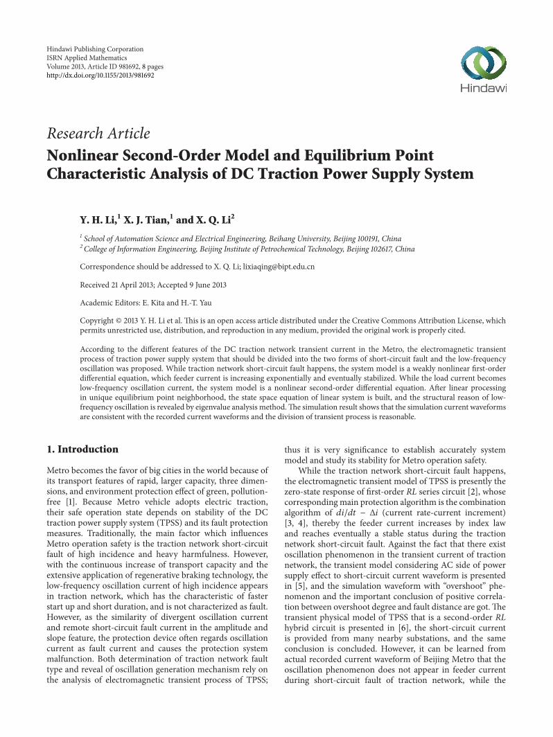
Figure 1 Transient current waveform of traction network
obvious low-frequency oscillation process appears in normaloperation stages so the electromagnetic transient process ofTPSS should be divide into the two forms of short circuit faultand the low-frequency oscillation
It can be learned from the waveform analysis of short-circuit and oscillation current that the electrical drive struc-ture of vehicle and operation status have great influence tooscillation process so the transient model of TPSS shouldtake vehicle factor into consideration Firstly the transientmodel of TPSS is established during the traction networkshort-circuit and the fault type is determined by the feedercurrent analysis of transition process and change featureSecondly the nonlinear second-order dynamic systemmodelconsidering vehicle factor and the corresponding linearsystemmodel in balance-point neighborhood are establishedand the structural reasons of low-frequency oscillation isconcluded by analysis of the state space matrix of linearsystem
2 Transient Current and Waveform Feature ofTraction Network
The function of DC TPSS is to change three-phase AC volt-age into DC 750V (or DC 1500V) voltage by step-downand rectifier and then provide power to vehicle by theoverhead contact line (or the contact rail)TheTPSS ismainlycomposed of DC traction substation feeder DC tractionnetwork (contact line and travel rail) and return line andits structure features are bilateral power supply and shortertransmission line
At present the two types of transient current waveformof traction network short-circuit fault and system low-frequency oscillation are recorded in line 1 of Beijing Metroas shown in Figure 1 In Figure 1(a) the protection started at100ms and the fault is cut off before it reaches steady statewhile in Figure 1(b) the protection started at 300ms andpower supply is cut off before it reaches peak
It can be seen from Figure 1(a) that the short-circuit faultcurrent waveform has the following features (1) the currentpulsation amplitude is very small before short-circuit fault
while the current rises exponentially and reaches peak (orsaturation value) in shorter time after fault (2) the current hasa certain initial value which indicates that traction network isfirstly in transmission condition and then happens to short-circuit fault and its change rule does follow the zero-stateresponse of first-order RL serials circuit These two featureshave been confirmed by the recorded short-circuit fault casesof traction network of Beijing Metro in the last two years
Figure 1(b) shows that the oscillation current has thefollowing features (1) the startup of oscillation is quick theduration is generally less than 1 s and the oscillation periodis about 100ms (2) the start-up point at the negative currentindicates that vehicle is in a regenerative braking state (3) theamplitude of oscillation current is small even smaller thanthe traction load current
It can be concluded by the previous analysis that thesetwo types of transient current have essential difference inwaveform morphology and generation mechanism There-fore the modeling and analysis of TPSS will be carried out inaccordance with two forms of traction network short-circuitfault and system low-frequency oscillation
3 Modeling and Analysis of TPSS during theTraction Network Fault
31 Physical Model of Traction Substation Generally it issuitable that the equivalent modeling of traction substationadopts the theorem of LC Thevenin in study and analysis ofTPSS electromagnetic transient process The main electricalequipment of traction substation is 24-pluse rectifier unit(combination of traction transformer and rectifier) and thework feature of rectifier unit is that its external characteristic(function relation between DC output voltage and loadcurrent) is a weakly nonlinear relationshipWhat is more theAC side equivalent inductancemakes little effect on operationof TPSS because of large leakage reactance of rectifier trans-former Therefore the equivalent physical model of tractionsubstation is the series circuit of ideal voltage source 119864 andinternal resistance r as shown in Figure 2
ISRN Applied Mathematics 3
r
E
Id
Vd+
minus
Figure 2 Equivalent physical model of traction substation
Obviously the absolute value of characteristic curve slopeis the internal resistance r and the intercept of y axis is thevoltage value of ideal voltage source E thereby the outputequation of substation is
119881119889 = 119864 minus 119868119889119903 (1)
32 SystemModeling and Qualitative Analysis The transmis-sion lines of TPSS are uniform structure their total lengthis generally less than 3 km and voltage is low thereby theequivalent resistance model of short-circuit line can be usedin modeling of transmission line Thus the electromagnetictransient physical model of TPSS during traction networkshort-circuit fault can be got according to the model ofsubstation and transmission line as shown in Figure 3
It can be learned from the circuit structure that theelectromagnetic transient physical model of TPSS is a weaklynonlinear first-order RL series circuit and the two series cir-cuits are independent In Figure 3 119889 is the distance betweensubstation A and substation B 119889119909 is the distance betweenshort-circuit point and substation A 119906119891 is the arc voltage(only relevant to the arc length) voltage value of ideal voltagesource is 1198640 and 1198941 and 1198942 are respectively feeder currentsprovided by substations A and B In addition if we assumedthat the resistance 1205880 and inductance 1205850 of unit length forcontact line and the resistance 1205881 and inductance 1205851 of unitlength for travel rail are constant value while the currentchanges then the contact line impedance (11988511 11988512) andtravel rail impedance (11988521 11988522) are proportional to distanceof power supply
According to the mesh current method and round direc-tion shown in Figure 3 the first-order differential equationsof feeder current based on small signal analysis method are
(1199031 + 120588119889119909) Δ1198941 + 120585119909119889Δ1198941
119889119905= Δ1198640 minus Δ119906119891
[1199032 + 120588 (119889 minus 119889119909)] Δ1198942 + 120585 (119889 minus 119889119909)119889Δ1198942
119889119905= Δ1198640 minus Δ119906119891
(2)
where 120588 = 1205880 + 1205881 and 120585 = 1205850 + 1205851
i1 i2Z11Z21
d
dx
r1
E0
Substation BSubstation A Z12 Z22
id
uf
III
r2
E0
minus
+
minus
+
minus
+
Figure 3 Transient physicalmodel of TPSS during traction networkfault
The time-domain solution of (2) is
Δ1198941 =Δ1198640 minus Δ119906119891
1199031 + 120588119889119909
(1 minus 119890minus((1199031+120588119889119909)120585119889119909)times119905)
≜ 1198941199011 minus 1198941198981
Δ1198942 =Δ1198640 minus Δ119906119891
1199032 + 120588 (119889 minus 119889119909)
times (1 minus 119890minus((1199032+120588(119889minus119889
119909))120585(119889minus119889
119909))times119905)
≜ 1198941199012 minus 1198941198982
(3)
It is shown in formula (3) that the small signal of feedercurrentsΔ1198941 andΔ1198942 contains two components of steady-stateand transient if the traction network short-circuit fault occursin 119905 = 0 That is the feeder current Δ1198941 contains steady-state component 1198941199011 and transient components 1198941198981 and thefeeder current Δ1198942 contains steady-state component 1198941199012 andtransient component 1198941198982 As time goes on the transientcomponent 1198941198981 and 1198941198982 will attenuate in accordance withthe law of exponential function while the feeder currentincreases exponentially and eventually stabilizes to a steady-state current
Through the real-time simulation of transient model ofTPSS carried in the digital simulation platformof RT-Lab thetime-domain transition process of feeder current is obtainedand the simulation result is shown in Figure 4
It can be seen from the simulation results that the simu-lation waveform is consistent with the recorded fault currentwaveform in change process fault steady-state current valueand first-orderRL circuit response characteristics are decidedby the value of substation internal resistance and tractionnetwork resistance at fault moment and feeder current valueis positive correlation to fault distance the change rule offeeder current follows the zero-state response of first-orderRL series circuit
4 Modeling and Analysis of TPSS during Low-Frequency Oscillation
Currently theAC speed regulation trainwithVVVF functionand EMU (electrical multiple units) is widely used in Beijing
4 ISRN Applied Mathematics
00
20
40
60
80
100
120
140
Curr
ent (
kA)
minus100 minus80 minus60 minus40 minus20 0 20 40 60 80 100Time (ms)
i1i2
Figure 4 Simulation waveform of feeder currents during tractionnetwork short circuit
Metro each train has usually six marshalling (4 EMUs + 2trailers) and eachEMU is equippedwith two sets ofAC speedregulation device with a filter capacitor of 12mF and a filterinductance of 6mH In addition all inverters and ACmotorsof vehicle can be equivalent to the series circuit of nonlinearnegative resistance and DC voltage source
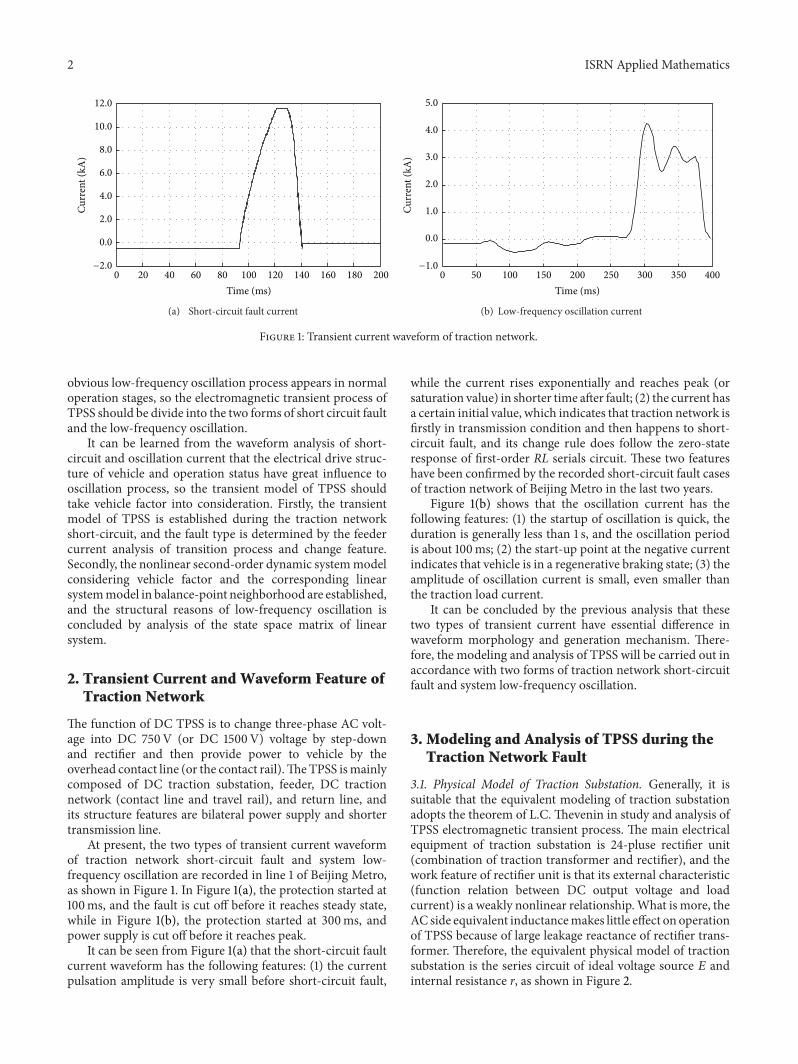
41 Physical Model of Low-Frequency Oscillation The aimof regenerative braking of Metro is to achieve the effect ofenergy saving by converting the part of vehicle kinetic energyinto electric power and feedback it to DC traction networkTherefore the operating status of regenerative braking isthat the traction motors are in running condition and thevoltage of traction network is higher than the voltage ofrectifier unit Considering that the low-frequency oscillationof TPSS occurs in regenerative braking condition obviouslythe vehicle is an important part of TPSS at this time Thusthe electromagnetic transient physical model of TPSS duringthe low-frequency oscillation is established by the modelof electric drive substation and transmission as shown inFigure 5(a)
It can be seen from Figure 5(a) that the transient networkphysical model of TPSS during low-frequency oscillation isa nonlinear second-order RLC hybrid series circuit networkand the DC voltage source of vehicle which contains a certainlow-frequency component can be regarded as the systemdisturbance source In the vehicle model part 119862119901 is the filtercapacitor 119871119901 is the filter inductance and 119903119898 is the equivalentnonlinear resistor of electric drive (traction converters andmotors)
To simplify the calculation and analysis the equiva-lent transformation of the transient model is carried andthe transformation results are shown in Figure 5(b) Thusaccording to the contrast analysis of circuit structure thequantitative relation of main circuit parameters is
119894 = 1198941 + 1198942
119903 =11990311199032
1199031 + 1199032
1198771 =120588119889119909 (119889 minus 119889119909)
119889
1198711 =120585119889119909 (119889 minus 119889119909)
119889+ 119871119901
120588 = 1205880 + 1205881
120585 = 1205850 + 1205851
(4)
42 Determination of the Equilibrium Point It can be con-cluded from Figure 5(b) that the system physical model is anonlinear second-order RLC hybrid circuit after equivalenttransformationTherefore the mathematical model of feedercurrent is a second-order nonlinear differential equationwhich can be described by two first-order differential equa-tions as
1198640 = (1198771 + 119903) 119894 + 1198711119889119894
119889119905+ 119906119888
119906119888 = 119903119898119894 + 119903119898119862119901
119889119906119888
119889119905+ 119864119898
(5)
Because it is difficult to discuss the phase diagram on theentire phase plane for formula (5) the qualitative informationis usually obtained by the discussion of local properties in theequilibrium point neighborhood and the solution propertiesin the equilibrium point neighborhood can be studied bylinearization method
While vehicle is in the regenerative braking status theoperation condition of its electric drive system is verycomplex If we assumed that the output power is constant andignore the energy loss of electrical equipment the voltage-current characteristic of nonlinear resistance 119903119898 is a functionrelationship of inverse proportion Therefore the externalcharacteristics of converter can be described as
119906119898119894119898 = minus119875 = minus119896
119903119898 = minus1199062
119888
119875
(6)
where 119906119898 and 119894119898 are respectively the output voltage andthe output current of converter 119896 is a positive real constantand 119875 is the output power of inverter
In formula (5) the equilibrium points meet conditions of119889119906119888119889119905 = 0 and 119889119894119889119905 = 0 so the second-order nonlineardifferential equations of the feeder current can be simplifiedas
(1198771 + 119903 + 119903119898) 119894 = 1198640 minus 119864119898 (7)
Formula (7) is a monotonic function and the voltage-current characteristic of nonlinear resistance 119903119898 is still amonotonic function after linear transformation therebythese two monotonic functions have only one intersectionpoint which indicates that the circuit working point is theonly equilibrium point Therefore after the inductances arereplaced with short circuit and the capacitors are replaced
ISRN Applied Mathematics 5
i1 i2Z11 Z21
d
dx
r1
E0
Substation BSubstation A
Z12 Z22
III
r2
E0
minus
+
minus
+
i
Lp
rm
Em
Cp
minus
+
(a) Transient model
R1
r
E0
Em
Cp uc
ibia
L1
rm
minus
+
minus
+
i
minus
+
(b) Equivalent transient model
Figure 5 Transient physical model of TPSS during low-frequency oscillation
with open circuit in Figure 5 the equilibrium working point119872(119909119890 119910119890) can be obtained using KVL that is
119872(119909119890 119910119890) = (1198640 minus 119864119898
1198771 + 119903 minus 119903119898
(1198771 + 119903) 119864119898 minus 1199031198981198640
1198771 + 119903 minus 119903119898
) (8)
43 Equilibrium Point Properties of the General Second-Order Dynamic Circuit Generally the equation of nonlinearsecond-order dynamic circuit can be described by formula(9) as follows
119889119909
119889119905= 119883 (119909 119910)
119889119910
119889119905= 119884 (119909 119910)
(9)
So formula (9) in the equilibrium point neighborhoodcan always be transformed into
[[[
[
119889119909
119889119905119889119910
119889119905
]]]
]
= [119886 119887
119888 119889] [119909
119910] + [
119891 (119909 119910)
119892 (119909 119910)] (10)
In formula (10) 119891(119909 119910) and 119892(119909 119910) are the functionsthat is composed of the quadratic term and the more orderitem and
119886 =120597119883
120597119909
10038161003816100381610038161003816100381610038161003816119909=119910=0 119887 =
120597119883
120597119910
10038161003816100381610038161003816100381610038161003816119909=119910=0
119888 =120597119884
120597119909
10038161003816100381610038161003816100381610038161003816119909=119910=0 119889 =
120597119884
120597119910
10038161003816100381610038161003816100381610038161003816119909=119910=0
(11)
Without considering the higher-order terms then
[[[
[
1198891205771
1198891199051198891205772
119889119905
]]]
]
= [119886 119887
119888 119889] [12057711205772] = A [1205771
1205772] (12)
Obviously the formula (12) is the linear equation of for-mula (9) in the neighborhood of equilibrium point and 1205771 =0 1205772 = 0 are the equilibrium points of formula (12) Ifthe matrix A does not exist eigenvalues with zero-real partthe equilibrium point of non linear equation is called thehyperbolic equilibrium point The trajectory shape in thehyperbolic equilibrium point has the same characteristicswith the trajectory shape of linear equations (12) in theequilibrium point Therefore when the equilibrium pointof the linear system is respectively a saddle point nodeand focus the equilibrium point of corresponding nonlinearsystem is also respectively saddle point node and focusand the trajectory of nonlinear system and linear system aretangent at the equilibrium point
44 Properties of Equilibrium Point during System Low-Frequ-ency Oscillation According to the previous linearizationmethod of second-order dynamic circuit and designating thetraction current 119894 and the filter capacitor voltage 119906119888 as statevariables the state space equation of the formula (5) in theneighborhood of equilibrium point 119872(119909119890 119910119890) is
[[[
[
119889119894
119889119905119889119906119888
119889119909
]]]
]
=[[[
[
minus1198771 + 119903
1198711
minus1
11987111
119862119901
minus1
119903119898119862119901
]]]
]
[119894
119906119888]
+[[[
[
1
1198711
0
01
119903119898119862119901
]]]
]
[1198640119864119898]
(13)
The compact form of (13) is
[
sdot
119894sdot
119906119888
] = A [ 119894119906119888] + B [1198640
119864119898] (14)
In formula (14) A is the state matrix and B is the inputmatrix
6 ISRN Applied Mathematics
Table 1 Relationship between eigenvalue and type of equilibriumpoint
Eigenvalues Type of equilibrium point1199012minus 4119902 gt 0 and 119901 gt 0 Stable node
1199012minus 4119902 gt 0 and 119901 lt 0 Unstable node
1199012minus 4119902 gt 0 and 119902 lt 0 Saddle
1199012minus 4119902 lt 0 and 119901 lt 0 Unstable focus
1199012minus 4119902 lt 0 and 119901 gt 0 Stable focus
119901 = 0 Uncertain
If we assume (1198940 1199061198880) to be the initial value of formula(14) of 119905 = 0 its solution can be expressed as
[119894
119906119888] = [
11989401199061198880] 119890119860119905≜ u119890119860119905 (15)
The linear system has only one equilibrium point119872(119909119890119910119890) and the property of the equilibrium point is decided bythe eigenvalue of matrix A
The characteristic equation is
det (120582I minus A) = 1205822 + (119903 + 11987711198711
+1
119903119898119862119901
)120582
+(119903 + 1198771) + 119903119898
1199031198981198711119862119901
= 0
(16)
The new variables 119901 and 119902 are defined as
119901 =119903 + 1198771
1198711
+1
119903119898119862119901
119902 =(119903 + 1198771) + 119903119898
1199031198981198711119862119901
(17)
Thus the eigenvalues of formula (16) are
1205821 1205822 =
minus119901 plusmn radic1199012 minus 4119902
2
(18)
When the parameters ofmatrixA change the eigenvalues1205821 1205822 will have lots of combination forms and the results areshown in Table 1 after being discussed
45 Analysis and Simulation of Divergent Low-FrequencyOscillation Considering the malfunction of relay protectcaused by divergent low-frequency oscillation it is necessaryto carry detailed analysis of divergent low-frequency oscilla-tion
When the divergent low-frequency oscillation occursthe system equilibrium point is an unstable focus and theeigenvalues 1205821 1205822 are a pair of conjugate roots of positivereal part that is 1205821 1205822 = 120590 plusmn 119895120596 so the conditions ofdivergent oscillation are
minus119903119898 gt1198711
119862119901 (1198771 + 119903)
[119903119898119862119901(1198771 + 119903) + 1198711]2
lt 41199031198981198711119862119901 [(119903 + 1198771) + 119903119898]
(19)
Many electrical parameters are involved in formula (19)and most of them are related to distance of power supplyso the results are difficult to obtain by direct calculationNow enumeration method is used to verify the structuralconditions of divergent oscillation
The output power range of Metro vehicles converter is0sim24MW the output voltage is 825V and then the changerange of resistance 119903119898 is
10038161003816100381610038161199031198981003816100381610038161003816 =1199062
119888
119875ge
8252
24 times 106= 02836 (Ω) (20)
In Figure 5 the filter inductor 119871119901 is 15mH and thefilter capacitor 119862119901 is 48mF (the four sets of electricaldrive units are parallel) The loop electrical parameters ofunit length 1205880 1205850 1205881 and 1205851 are respectively 0019 Ωkm1139mHkm 0016 Ωkm and 0328mHkm if the actualaverage of resistance and inductance is adopted Suppose thatthe power supply distance between two substations (119889) is2 km the internal resistance of substation 119903 is 004 Ω andfault distance 119889119909 is 05 km in representative instance andsubstitute these electrical parameters into formula (4) then
1198771 = 001313Ω
1198711 = 20501mH(21)
Then the parameters1198771 1198711 119903 119871119901 and 119862119901 are substi-tuted into formula (19) and the result is
10038161003816100381610038161199031198981003816100381610038161003816 gt 08039Ω (22)
Therefore while |119903119898| gt 08039Ω the system configura-tion is unstable
Frequency119891 and the damping ratio 120589 (this case is negativeand which show diverging effect) are the two importantindexes in describing oscillatory waveform morphology sothe relationship between indexes and electrical parameterscan be expressed as
119891 = 2120587120596
120589 =minus120590
radic1205902 + 1205962
120590 =1
2(119903 + 1198771
1198711
+1
119903119898119862119901
)
1205962=(119903 + 1198771) minus 119903119898
1199031198981198711119862119901
(23)
Generally there exists condition of |119903119898| ≫ (119903 + 1198771) informula (23) so
119891 asymp2120587
radic1198711119862119901
(24)
Now in order to clarify the feature of system divergentoscillation the frequency 119891 and the damping ratio 120590 arecalculated by an actual example Assuming that the actual
ISRN Applied Mathematics 7
0 50 100 150 200 250 300
001020304050607080
minus10
Curr
ent (
kA)
Time (ms)
i1i2
Figure 6 Simulation waveform of low-frequency oscillation
output power of the converter is 80 of the maximum powerand the output voltage is 825V then
10038161003816100381610038161199031198981003816100381610038161003816 =1199062
119888
119875=
8252
24 times 106 times 80= 3545 (Ω) (25)
Substitute 119903119898 = minus3545 (Ω) and other electrical parame-ters (1198771 1198711 119871119901 119903 and 119862119901) into formula (23) and the resultis
119891 = 1223Hz
120585 = minus2314(26)
From the calculation results we can conclude the follow-ing (1) the change of system oscillation frequency is smalland its calculation value is basically consistent with the actualoscillation frequency (2) the damping ratio is relatively largein the neighborhood of equilibrium point which indicatesthat the start up of system divergent oscillation is fast
In addition as can be learned from qualitative analysisof formula (16) and (19) the equivalent nonlinear negativeresistance is the fundamental reason of system structureinstability Considering that in system model the electricalparameters that can be easily adjusted are filter capac-itor 119862119901 and filter inductor 119871119901 and the system structurestability can be improved by reducing 119862119901 and increasing 119871119901However it is required to reduce the cut off frequencyof low-pass filter by increasing 119862119901119871119901 in order to preventvehicle disturbance into the TPSS so the adjustable marginof structure parameters is very smaller
Through the real-time simulation of low-frequency oscil-lation transient model of TPSS carried in the digital simula-tion platform of RT-Lab the time-domain transition processof feeder current is obtained as shown in Figure 6
It can be seen from the simulation results that the simula-tionwaveform is consistent with the recorded divergent oscil-lation current waveform in change process the oscillationfrequency is mainly determined by filter capacitor 119862119901 andfilter induction 119871119901 and the positive damping ratio is mainlyaffected by the equivalent resistance 119903119898 of electric drive
5 Conclusion
Currently there exist two types of transient current in theDC traction network namely short-circuit fault currentwith increasing exponentially and low-frequency oscillatingcurrent with faster startup and short duration Because theshort circuit fault of traction network canmake great harm tosystem the action of short-circuit is characterized as a seri-ous fault The divergent low-frequency oscillation does notbelong to short-circuit fault but it will cause malfunction ofrelay protection because of the imperfect of electromagnetictransientmodel of TPSSTherefore the two types of transientcurrent have essential difference in waveform feature andgeneration mechanism
When the short-circuit fault of DC traction networkoccurs the electromagnetic transient physical model of TPSSis a weakly nonlinear first-order RL series circuit and themathematical model of feeder current is a weakly nonlinearfirst-order differential equations based on the small-signalanalysismethods It can be learned from analysis of the feedercurrent time-domain solution that the feeder current is com-posed of steady-state component and transient componentsand the steady-state component is independent of time whilethe transient component will decrease exponentially withtimeTherefore the feeder current will increase exponentiallyand eventually stabilize to a steady-state current whichindicates that the change of feeder current is a monotonicallyincreasing process In addition it can be learned from sim-ulation experiment that the feeder current value is positivlycorrelated with fault distance so the short-circuit fault typecan be judged by the value of feeder current
It can be learned from waveform feature of transientcurrent that the system low-frequency oscillation appears invehicle regenerative braking state and the structure of thesystem itself is a first-orderRL series circuit hence the vehiclemust be incorporated in the TPSS in transient modelingTheequivalent model of vehicle electric drive is a series circuitof DC voltage source and non-linear negative resistance sothe electromagnetic transient physical model of TPSS withvehicles is a nonlinear second-order RLC hybrid circuit andthe mathematical model of feeder current is a nonlinearsecond-order differential equations
The transient model of TPSS with vehicle is a complexnonlinear second-order dynamic system so it is a relativelysimple method in discussing the stability of system structurethat the linear process of model is carried in the neigh-borhood of equilibrium point The operating point is theequilibrium point of the system thus the transient modelcan be transformed into a linear system in the neighborhoodof operating point As can be learned by analysis of thestate space matrix analysis of linear system the equivalentresistance of electric drive is the main electrical parametersthat affect system instability and positive damping processwhile the system oscillation frequency depends mainly onfilter capacitor and filter inductor In addition the frequencyis the essential attribute of system structure and its changeis small so the relay protection algorithm of DC tractionnetwork based on the frequency characteristic can effectivelydistinguish oscillation current and fault current
8 ISRN Applied Mathematics
Acknowledgment
This paper was supported by Scientific Research and Devel-opment Planning Projects ldquoStudy of Automation SystemsSolutions and Technical Specifications in Traction PowerSupplyrdquo in Ministry of Railways China under Grant2007J022
References
[1] X Li and L Zuo ldquoEnergy spectrum and eigenvector of DCtraction power supply short-circuit currentrdquo Transactions ofChina Electrotechnical Society vol 25 no 11 pp 164ndash168 2010
[2] J C Brown J Allan and BMellitt ldquoCalculation of remote shortcircuit fault currents for DC railwaysrdquo IEE Proceedings B vol139 no 4 pp 289ndash294 1992
[3] B Lang ldquoResearch on feeder protection for DC traction powersupply systemrdquo Journal of Beijing Jiaotong University vol 33 no5 pp 65ndash68 2009
[4] G F Wang Y K Sun and K H Chen ldquoDDL protection insubway DC traction power supply systemrdquo Proceedings of theCSU-EPSA vol 19 no 1 pp 59ndash62 2007
[5] K Kongwei Q Qinlijun Y Yangqixun and D Dingfuhua ldquoDCside short circuit transient simulation of DC traction powersupply systemrdquo in Proceedings of the International Conferenceon Power System Technology (POWERCON rsquo04) pp 182ndash186November 2004
[6] C L Pires S I Nabeta and J R Cardoso ldquoSecond-ordermodelfor remote and close-up short-circuit faults currents on DCtraction supplyrdquo IET Power Electronics vol 1 no 3 pp 348ndash3552008
Submit your manuscripts athttpwwwhindawicom
Hindawi Publishing Corporationhttpwwwhindawicom Volume 2014
MathematicsJournal of
Hindawi Publishing Corporationhttpwwwhindawicom Volume 2014
Mathematical Problems in Engineering
Hindawi Publishing Corporationhttpwwwhindawicom
Differential EquationsInternational Journal of
Volume 2014
Applied MathematicsJournal of
Hindawi Publishing Corporationhttpwwwhindawicom Volume 2014
Probability and StatisticsHindawi Publishing Corporationhttpwwwhindawicom Volume 2014
Journal of
Hindawi Publishing Corporationhttpwwwhindawicom Volume 2014
Mathematical PhysicsAdvances in
Complex AnalysisJournal of
Hindawi Publishing Corporationhttpwwwhindawicom Volume 2014
OptimizationJournal of
Hindawi Publishing Corporationhttpwwwhindawicom Volume 2014
CombinatoricsHindawi Publishing Corporationhttpwwwhindawicom Volume 2014
International Journal of
Hindawi Publishing Corporationhttpwwwhindawicom Volume 2014
Operations ResearchAdvances in
Journal of
Hindawi Publishing Corporationhttpwwwhindawicom Volume 2014
Function Spaces
Abstract and Applied AnalysisHindawi Publishing Corporationhttpwwwhindawicom Volume 2014
International Journal of Mathematics and Mathematical Sciences
Hindawi Publishing Corporationhttpwwwhindawicom Volume 2014
The Scientific World JournalHindawi Publishing Corporation httpwwwhindawicom Volume 2014
Hindawi Publishing Corporationhttpwwwhindawicom Volume 2014
Algebra
Discrete Dynamics in Nature and Society
Hindawi Publishing Corporationhttpwwwhindawicom Volume 2014
Hindawi Publishing Corporationhttpwwwhindawicom Volume 2014
Decision SciencesAdvances in
Discrete MathematicsJournal of
Hindawi Publishing Corporationhttpwwwhindawicom
Volume 2014 Hindawi Publishing Corporationhttpwwwhindawicom Volume 2014
Stochastic AnalysisInternational Journal of
2 ISRN Applied Mathematics
0 20 40 60 80 100 120 140 160 180 200
00
20
40
60
80
100
120
Curr
ent (
kA)
minus20
Time (ms)
(a) Short-circuit fault current
Time (ms)0 50 100 150 200 250 300 350 400
00
10
20
30
40
50
minus10
Curr
ent (
kA)
(b) Low-frequency oscillation current
Figure 1 Transient current waveform of traction network
obvious low-frequency oscillation process appears in normaloperation stages so the electromagnetic transient process ofTPSS should be divide into the two forms of short circuit faultand the low-frequency oscillation
It can be learned from the waveform analysis of short-circuit and oscillation current that the electrical drive struc-ture of vehicle and operation status have great influence tooscillation process so the transient model of TPSS shouldtake vehicle factor into consideration Firstly the transientmodel of TPSS is established during the traction networkshort-circuit and the fault type is determined by the feedercurrent analysis of transition process and change featureSecondly the nonlinear second-order dynamic systemmodelconsidering vehicle factor and the corresponding linearsystemmodel in balance-point neighborhood are establishedand the structural reasons of low-frequency oscillation isconcluded by analysis of the state space matrix of linearsystem
2 Transient Current and Waveform Feature ofTraction Network
The function of DC TPSS is to change three-phase AC volt-age into DC 750V (or DC 1500V) voltage by step-downand rectifier and then provide power to vehicle by theoverhead contact line (or the contact rail)TheTPSS ismainlycomposed of DC traction substation feeder DC tractionnetwork (contact line and travel rail) and return line andits structure features are bilateral power supply and shortertransmission line
At present the two types of transient current waveformof traction network short-circuit fault and system low-frequency oscillation are recorded in line 1 of Beijing Metroas shown in Figure 1 In Figure 1(a) the protection started at100ms and the fault is cut off before it reaches steady statewhile in Figure 1(b) the protection started at 300ms andpower supply is cut off before it reaches peak
It can be seen from Figure 1(a) that the short-circuit faultcurrent waveform has the following features (1) the currentpulsation amplitude is very small before short-circuit fault
while the current rises exponentially and reaches peak (orsaturation value) in shorter time after fault (2) the current hasa certain initial value which indicates that traction network isfirstly in transmission condition and then happens to short-circuit fault and its change rule does follow the zero-stateresponse of first-order RL serials circuit These two featureshave been confirmed by the recorded short-circuit fault casesof traction network of Beijing Metro in the last two years
Figure 1(b) shows that the oscillation current has thefollowing features (1) the startup of oscillation is quick theduration is generally less than 1 s and the oscillation periodis about 100ms (2) the start-up point at the negative currentindicates that vehicle is in a regenerative braking state (3) theamplitude of oscillation current is small even smaller thanthe traction load current
It can be concluded by the previous analysis that thesetwo types of transient current have essential difference inwaveform morphology and generation mechanism There-fore the modeling and analysis of TPSS will be carried out inaccordance with two forms of traction network short-circuitfault and system low-frequency oscillation
3 Modeling and Analysis of TPSS during theTraction Network Fault
31 Physical Model of Traction Substation Generally it issuitable that the equivalent modeling of traction substationadopts the theorem of LC Thevenin in study and analysis ofTPSS electromagnetic transient process The main electricalequipment of traction substation is 24-pluse rectifier unit(combination of traction transformer and rectifier) and thework feature of rectifier unit is that its external characteristic(function relation between DC output voltage and loadcurrent) is a weakly nonlinear relationshipWhat is more theAC side equivalent inductancemakes little effect on operationof TPSS because of large leakage reactance of rectifier trans-former Therefore the equivalent physical model of tractionsubstation is the series circuit of ideal voltage source 119864 andinternal resistance r as shown in Figure 2
ISRN Applied Mathematics 3
r
E
Id
Vd+
minus
Figure 2 Equivalent physical model of traction substation
Obviously the absolute value of characteristic curve slopeis the internal resistance r and the intercept of y axis is thevoltage value of ideal voltage source E thereby the outputequation of substation is
119881119889 = 119864 minus 119868119889119903 (1)
32 SystemModeling and Qualitative Analysis The transmis-sion lines of TPSS are uniform structure their total lengthis generally less than 3 km and voltage is low thereby theequivalent resistance model of short-circuit line can be usedin modeling of transmission line Thus the electromagnetictransient physical model of TPSS during traction networkshort-circuit fault can be got according to the model ofsubstation and transmission line as shown in Figure 3
It can be learned from the circuit structure that theelectromagnetic transient physical model of TPSS is a weaklynonlinear first-order RL series circuit and the two series cir-cuits are independent In Figure 3 119889 is the distance betweensubstation A and substation B 119889119909 is the distance betweenshort-circuit point and substation A 119906119891 is the arc voltage(only relevant to the arc length) voltage value of ideal voltagesource is 1198640 and 1198941 and 1198942 are respectively feeder currentsprovided by substations A and B In addition if we assumedthat the resistance 1205880 and inductance 1205850 of unit length forcontact line and the resistance 1205881 and inductance 1205851 of unitlength for travel rail are constant value while the currentchanges then the contact line impedance (11988511 11988512) andtravel rail impedance (11988521 11988522) are proportional to distanceof power supply
According to the mesh current method and round direc-tion shown in Figure 3 the first-order differential equationsof feeder current based on small signal analysis method are
(1199031 + 120588119889119909) Δ1198941 + 120585119909119889Δ1198941
119889119905= Δ1198640 minus Δ119906119891
[1199032 + 120588 (119889 minus 119889119909)] Δ1198942 + 120585 (119889 minus 119889119909)119889Δ1198942
119889119905= Δ1198640 minus Δ119906119891
(2)
where 120588 = 1205880 + 1205881 and 120585 = 1205850 + 1205851
i1 i2Z11Z21
d
dx
r1
E0
Substation BSubstation A Z12 Z22
id
uf
III
r2
E0
minus
+
minus
+
minus
+
Figure 3 Transient physicalmodel of TPSS during traction networkfault
The time-domain solution of (2) is
Δ1198941 =Δ1198640 minus Δ119906119891
1199031 + 120588119889119909
(1 minus 119890minus((1199031+120588119889119909)120585119889119909)times119905)
≜ 1198941199011 minus 1198941198981
Δ1198942 =Δ1198640 minus Δ119906119891
1199032 + 120588 (119889 minus 119889119909)
times (1 minus 119890minus((1199032+120588(119889minus119889
119909))120585(119889minus119889
119909))times119905)
≜ 1198941199012 minus 1198941198982
(3)
It is shown in formula (3) that the small signal of feedercurrentsΔ1198941 andΔ1198942 contains two components of steady-stateand transient if the traction network short-circuit fault occursin 119905 = 0 That is the feeder current Δ1198941 contains steady-state component 1198941199011 and transient components 1198941198981 and thefeeder current Δ1198942 contains steady-state component 1198941199012 andtransient component 1198941198982 As time goes on the transientcomponent 1198941198981 and 1198941198982 will attenuate in accordance withthe law of exponential function while the feeder currentincreases exponentially and eventually stabilizes to a steady-state current
Through the real-time simulation of transient model ofTPSS carried in the digital simulation platformof RT-Lab thetime-domain transition process of feeder current is obtainedand the simulation result is shown in Figure 4
It can be seen from the simulation results that the simu-lation waveform is consistent with the recorded fault currentwaveform in change process fault steady-state current valueand first-orderRL circuit response characteristics are decidedby the value of substation internal resistance and tractionnetwork resistance at fault moment and feeder current valueis positive correlation to fault distance the change rule offeeder current follows the zero-state response of first-orderRL series circuit
4 Modeling and Analysis of TPSS during Low-Frequency Oscillation
Currently theAC speed regulation trainwithVVVF functionand EMU (electrical multiple units) is widely used in Beijing
4 ISRN Applied Mathematics
00
20
40
60
80
100
120
140
Curr
ent (
kA)
minus100 minus80 minus60 minus40 minus20 0 20 40 60 80 100Time (ms)
i1i2
Figure 4 Simulation waveform of feeder currents during tractionnetwork short circuit
Metro each train has usually six marshalling (4 EMUs + 2trailers) and eachEMU is equippedwith two sets ofAC speedregulation device with a filter capacitor of 12mF and a filterinductance of 6mH In addition all inverters and ACmotorsof vehicle can be equivalent to the series circuit of nonlinearnegative resistance and DC voltage source
41 Physical Model of Low-Frequency Oscillation The aimof regenerative braking of Metro is to achieve the effect ofenergy saving by converting the part of vehicle kinetic energyinto electric power and feedback it to DC traction networkTherefore the operating status of regenerative braking isthat the traction motors are in running condition and thevoltage of traction network is higher than the voltage ofrectifier unit Considering that the low-frequency oscillationof TPSS occurs in regenerative braking condition obviouslythe vehicle is an important part of TPSS at this time Thusthe electromagnetic transient physical model of TPSS duringthe low-frequency oscillation is established by the modelof electric drive substation and transmission as shown inFigure 5(a)
It can be seen from Figure 5(a) that the transient networkphysical model of TPSS during low-frequency oscillation isa nonlinear second-order RLC hybrid series circuit networkand the DC voltage source of vehicle which contains a certainlow-frequency component can be regarded as the systemdisturbance source In the vehicle model part 119862119901 is the filtercapacitor 119871119901 is the filter inductance and 119903119898 is the equivalentnonlinear resistor of electric drive (traction converters andmotors)
To simplify the calculation and analysis the equiva-lent transformation of the transient model is carried andthe transformation results are shown in Figure 5(b) Thusaccording to the contrast analysis of circuit structure thequantitative relation of main circuit parameters is
119894 = 1198941 + 1198942
119903 =11990311199032
1199031 + 1199032
1198771 =120588119889119909 (119889 minus 119889119909)
119889
1198711 =120585119889119909 (119889 minus 119889119909)
119889+ 119871119901
120588 = 1205880 + 1205881
120585 = 1205850 + 1205851
(4)
42 Determination of the Equilibrium Point It can be con-cluded from Figure 5(b) that the system physical model is anonlinear second-order RLC hybrid circuit after equivalenttransformationTherefore the mathematical model of feedercurrent is a second-order nonlinear differential equationwhich can be described by two first-order differential equa-tions as
1198640 = (1198771 + 119903) 119894 + 1198711119889119894
119889119905+ 119906119888
119906119888 = 119903119898119894 + 119903119898119862119901
119889119906119888
119889119905+ 119864119898
(5)
Because it is difficult to discuss the phase diagram on theentire phase plane for formula (5) the qualitative informationis usually obtained by the discussion of local properties in theequilibrium point neighborhood and the solution propertiesin the equilibrium point neighborhood can be studied bylinearization method
While vehicle is in the regenerative braking status theoperation condition of its electric drive system is verycomplex If we assumed that the output power is constant andignore the energy loss of electrical equipment the voltage-current characteristic of nonlinear resistance 119903119898 is a functionrelationship of inverse proportion Therefore the externalcharacteristics of converter can be described as
119906119898119894119898 = minus119875 = minus119896
119903119898 = minus1199062
119888
119875
(6)
where 119906119898 and 119894119898 are respectively the output voltage andthe output current of converter 119896 is a positive real constantand 119875 is the output power of inverter
In formula (5) the equilibrium points meet conditions of119889119906119888119889119905 = 0 and 119889119894119889119905 = 0 so the second-order nonlineardifferential equations of the feeder current can be simplifiedas
(1198771 + 119903 + 119903119898) 119894 = 1198640 minus 119864119898 (7)
Formula (7) is a monotonic function and the voltage-current characteristic of nonlinear resistance 119903119898 is still amonotonic function after linear transformation therebythese two monotonic functions have only one intersectionpoint which indicates that the circuit working point is theonly equilibrium point Therefore after the inductances arereplaced with short circuit and the capacitors are replaced
ISRN Applied Mathematics 5
i1 i2Z11 Z21
d
dx
r1
E0
Substation BSubstation A
Z12 Z22
III
r2
E0
minus
+
minus
+
i
Lp
rm
Em
Cp
minus
+
(a) Transient model
R1
r
E0
Em
Cp uc
ibia
L1
rm
minus
+
minus
+
i
minus
+
(b) Equivalent transient model
Figure 5 Transient physical model of TPSS during low-frequency oscillation
with open circuit in Figure 5 the equilibrium working point119872(119909119890 119910119890) can be obtained using KVL that is
119872(119909119890 119910119890) = (1198640 minus 119864119898
1198771 + 119903 minus 119903119898
(1198771 + 119903) 119864119898 minus 1199031198981198640
1198771 + 119903 minus 119903119898
) (8)
43 Equilibrium Point Properties of the General Second-Order Dynamic Circuit Generally the equation of nonlinearsecond-order dynamic circuit can be described by formula(9) as follows
119889119909
119889119905= 119883 (119909 119910)
119889119910
119889119905= 119884 (119909 119910)
(9)
So formula (9) in the equilibrium point neighborhoodcan always be transformed into
[[[
[
119889119909
119889119905119889119910
119889119905
]]]
]
= [119886 119887
119888 119889] [119909
119910] + [
119891 (119909 119910)
119892 (119909 119910)] (10)
In formula (10) 119891(119909 119910) and 119892(119909 119910) are the functionsthat is composed of the quadratic term and the more orderitem and
119886 =120597119883
120597119909
10038161003816100381610038161003816100381610038161003816119909=119910=0 119887 =
120597119883
120597119910
10038161003816100381610038161003816100381610038161003816119909=119910=0
119888 =120597119884
120597119909
10038161003816100381610038161003816100381610038161003816119909=119910=0 119889 =
120597119884
120597119910
10038161003816100381610038161003816100381610038161003816119909=119910=0
(11)
Without considering the higher-order terms then
[[[
[
1198891205771
1198891199051198891205772
119889119905
]]]
]
= [119886 119887
119888 119889] [12057711205772] = A [1205771
1205772] (12)
Obviously the formula (12) is the linear equation of for-mula (9) in the neighborhood of equilibrium point and 1205771 =0 1205772 = 0 are the equilibrium points of formula (12) Ifthe matrix A does not exist eigenvalues with zero-real partthe equilibrium point of non linear equation is called thehyperbolic equilibrium point The trajectory shape in thehyperbolic equilibrium point has the same characteristicswith the trajectory shape of linear equations (12) in theequilibrium point Therefore when the equilibrium pointof the linear system is respectively a saddle point nodeand focus the equilibrium point of corresponding nonlinearsystem is also respectively saddle point node and focusand the trajectory of nonlinear system and linear system aretangent at the equilibrium point
44 Properties of Equilibrium Point during System Low-Frequ-ency Oscillation According to the previous linearizationmethod of second-order dynamic circuit and designating thetraction current 119894 and the filter capacitor voltage 119906119888 as statevariables the state space equation of the formula (5) in theneighborhood of equilibrium point 119872(119909119890 119910119890) is
[[[
[
119889119894
119889119905119889119906119888
119889119909
]]]
]
=[[[
[
minus1198771 + 119903
1198711
minus1
11987111
119862119901
minus1
119903119898119862119901
]]]
]
[119894
119906119888]
+[[[
[
1
1198711
0
01
119903119898119862119901
]]]
]
[1198640119864119898]
(13)
The compact form of (13) is
[
sdot
119894sdot
119906119888
] = A [ 119894119906119888] + B [1198640
119864119898] (14)
In formula (14) A is the state matrix and B is the inputmatrix
6 ISRN Applied Mathematics
Table 1 Relationship between eigenvalue and type of equilibriumpoint
Eigenvalues Type of equilibrium point1199012minus 4119902 gt 0 and 119901 gt 0 Stable node
1199012minus 4119902 gt 0 and 119901 lt 0 Unstable node
1199012minus 4119902 gt 0 and 119902 lt 0 Saddle
1199012minus 4119902 lt 0 and 119901 lt 0 Unstable focus
1199012minus 4119902 lt 0 and 119901 gt 0 Stable focus
119901 = 0 Uncertain
If we assume (1198940 1199061198880) to be the initial value of formula(14) of 119905 = 0 its solution can be expressed as
[119894
119906119888] = [
11989401199061198880] 119890119860119905≜ u119890119860119905 (15)
The linear system has only one equilibrium point119872(119909119890119910119890) and the property of the equilibrium point is decided bythe eigenvalue of matrix A
The characteristic equation is
det (120582I minus A) = 1205822 + (119903 + 11987711198711
+1
119903119898119862119901
)120582
+(119903 + 1198771) + 119903119898
1199031198981198711119862119901
= 0
(16)
The new variables 119901 and 119902 are defined as
119901 =119903 + 1198771
1198711
+1
119903119898119862119901
119902 =(119903 + 1198771) + 119903119898
1199031198981198711119862119901
(17)
Thus the eigenvalues of formula (16) are
1205821 1205822 =
minus119901 plusmn radic1199012 minus 4119902
2
(18)
When the parameters ofmatrixA change the eigenvalues1205821 1205822 will have lots of combination forms and the results areshown in Table 1 after being discussed
45 Analysis and Simulation of Divergent Low-FrequencyOscillation Considering the malfunction of relay protectcaused by divergent low-frequency oscillation it is necessaryto carry detailed analysis of divergent low-frequency oscilla-tion
When the divergent low-frequency oscillation occursthe system equilibrium point is an unstable focus and theeigenvalues 1205821 1205822 are a pair of conjugate roots of positivereal part that is 1205821 1205822 = 120590 plusmn 119895120596 so the conditions ofdivergent oscillation are
minus119903119898 gt1198711
119862119901 (1198771 + 119903)
[119903119898119862119901(1198771 + 119903) + 1198711]2
lt 41199031198981198711119862119901 [(119903 + 1198771) + 119903119898]
(19)
Many electrical parameters are involved in formula (19)and most of them are related to distance of power supplyso the results are difficult to obtain by direct calculationNow enumeration method is used to verify the structuralconditions of divergent oscillation
The output power range of Metro vehicles converter is0sim24MW the output voltage is 825V and then the changerange of resistance 119903119898 is
10038161003816100381610038161199031198981003816100381610038161003816 =1199062
119888
119875ge
8252
24 times 106= 02836 (Ω) (20)
In Figure 5 the filter inductor 119871119901 is 15mH and thefilter capacitor 119862119901 is 48mF (the four sets of electricaldrive units are parallel) The loop electrical parameters ofunit length 1205880 1205850 1205881 and 1205851 are respectively 0019 Ωkm1139mHkm 0016 Ωkm and 0328mHkm if the actualaverage of resistance and inductance is adopted Suppose thatthe power supply distance between two substations (119889) is2 km the internal resistance of substation 119903 is 004 Ω andfault distance 119889119909 is 05 km in representative instance andsubstitute these electrical parameters into formula (4) then
1198771 = 001313Ω
1198711 = 20501mH(21)
Then the parameters1198771 1198711 119903 119871119901 and 119862119901 are substi-tuted into formula (19) and the result is
10038161003816100381610038161199031198981003816100381610038161003816 gt 08039Ω (22)
Therefore while |119903119898| gt 08039Ω the system configura-tion is unstable
Frequency119891 and the damping ratio 120589 (this case is negativeand which show diverging effect) are the two importantindexes in describing oscillatory waveform morphology sothe relationship between indexes and electrical parameterscan be expressed as
119891 = 2120587120596
120589 =minus120590
radic1205902 + 1205962
120590 =1
2(119903 + 1198771
1198711
+1
119903119898119862119901
)
1205962=(119903 + 1198771) minus 119903119898
1199031198981198711119862119901
(23)
Generally there exists condition of |119903119898| ≫ (119903 + 1198771) informula (23) so
119891 asymp2120587
radic1198711119862119901
(24)
Now in order to clarify the feature of system divergentoscillation the frequency 119891 and the damping ratio 120590 arecalculated by an actual example Assuming that the actual
ISRN Applied Mathematics 7
0 50 100 150 200 250 300
001020304050607080
minus10
Curr
ent (
kA)
Time (ms)
i1i2
Figure 6 Simulation waveform of low-frequency oscillation
output power of the converter is 80 of the maximum powerand the output voltage is 825V then
10038161003816100381610038161199031198981003816100381610038161003816 =1199062
119888
119875=
8252
24 times 106 times 80= 3545 (Ω) (25)
Substitute 119903119898 = minus3545 (Ω) and other electrical parame-ters (1198771 1198711 119871119901 119903 and 119862119901) into formula (23) and the resultis
119891 = 1223Hz
120585 = minus2314(26)
From the calculation results we can conclude the follow-ing (1) the change of system oscillation frequency is smalland its calculation value is basically consistent with the actualoscillation frequency (2) the damping ratio is relatively largein the neighborhood of equilibrium point which indicatesthat the start up of system divergent oscillation is fast
In addition as can be learned from qualitative analysisof formula (16) and (19) the equivalent nonlinear negativeresistance is the fundamental reason of system structureinstability Considering that in system model the electricalparameters that can be easily adjusted are filter capac-itor 119862119901 and filter inductor 119871119901 and the system structurestability can be improved by reducing 119862119901 and increasing 119871119901However it is required to reduce the cut off frequencyof low-pass filter by increasing 119862119901119871119901 in order to preventvehicle disturbance into the TPSS so the adjustable marginof structure parameters is very smaller
Through the real-time simulation of low-frequency oscil-lation transient model of TPSS carried in the digital simula-tion platform of RT-Lab the time-domain transition processof feeder current is obtained as shown in Figure 6
It can be seen from the simulation results that the simula-tionwaveform is consistent with the recorded divergent oscil-lation current waveform in change process the oscillationfrequency is mainly determined by filter capacitor 119862119901 andfilter induction 119871119901 and the positive damping ratio is mainlyaffected by the equivalent resistance 119903119898 of electric drive
5 Conclusion
Currently there exist two types of transient current in theDC traction network namely short-circuit fault currentwith increasing exponentially and low-frequency oscillatingcurrent with faster startup and short duration Because theshort circuit fault of traction network canmake great harm tosystem the action of short-circuit is characterized as a seri-ous fault The divergent low-frequency oscillation does notbelong to short-circuit fault but it will cause malfunction ofrelay protection because of the imperfect of electromagnetictransientmodel of TPSSTherefore the two types of transientcurrent have essential difference in waveform feature andgeneration mechanism
When the short-circuit fault of DC traction networkoccurs the electromagnetic transient physical model of TPSSis a weakly nonlinear first-order RL series circuit and themathematical model of feeder current is a weakly nonlinearfirst-order differential equations based on the small-signalanalysismethods It can be learned from analysis of the feedercurrent time-domain solution that the feeder current is com-posed of steady-state component and transient componentsand the steady-state component is independent of time whilethe transient component will decrease exponentially withtimeTherefore the feeder current will increase exponentiallyand eventually stabilize to a steady-state current whichindicates that the change of feeder current is a monotonicallyincreasing process In addition it can be learned from sim-ulation experiment that the feeder current value is positivlycorrelated with fault distance so the short-circuit fault typecan be judged by the value of feeder current
It can be learned from waveform feature of transientcurrent that the system low-frequency oscillation appears invehicle regenerative braking state and the structure of thesystem itself is a first-orderRL series circuit hence the vehiclemust be incorporated in the TPSS in transient modelingTheequivalent model of vehicle electric drive is a series circuitof DC voltage source and non-linear negative resistance sothe electromagnetic transient physical model of TPSS withvehicles is a nonlinear second-order RLC hybrid circuit andthe mathematical model of feeder current is a nonlinearsecond-order differential equations
The transient model of TPSS with vehicle is a complexnonlinear second-order dynamic system so it is a relativelysimple method in discussing the stability of system structurethat the linear process of model is carried in the neigh-borhood of equilibrium point The operating point is theequilibrium point of the system thus the transient modelcan be transformed into a linear system in the neighborhoodof operating point As can be learned by analysis of thestate space matrix analysis of linear system the equivalentresistance of electric drive is the main electrical parametersthat affect system instability and positive damping processwhile the system oscillation frequency depends mainly onfilter capacitor and filter inductor In addition the frequencyis the essential attribute of system structure and its changeis small so the relay protection algorithm of DC tractionnetwork based on the frequency characteristic can effectivelydistinguish oscillation current and fault current
8 ISRN Applied Mathematics
Acknowledgment
This paper was supported by Scientific Research and Devel-opment Planning Projects ldquoStudy of Automation SystemsSolutions and Technical Specifications in Traction PowerSupplyrdquo in Ministry of Railways China under Grant2007J022
References
[1] X Li and L Zuo ldquoEnergy spectrum and eigenvector of DCtraction power supply short-circuit currentrdquo Transactions ofChina Electrotechnical Society vol 25 no 11 pp 164ndash168 2010
[2] J C Brown J Allan and BMellitt ldquoCalculation of remote shortcircuit fault currents for DC railwaysrdquo IEE Proceedings B vol139 no 4 pp 289ndash294 1992
[3] B Lang ldquoResearch on feeder protection for DC traction powersupply systemrdquo Journal of Beijing Jiaotong University vol 33 no5 pp 65ndash68 2009
[4] G F Wang Y K Sun and K H Chen ldquoDDL protection insubway DC traction power supply systemrdquo Proceedings of theCSU-EPSA vol 19 no 1 pp 59ndash62 2007
[5] K Kongwei Q Qinlijun Y Yangqixun and D Dingfuhua ldquoDCside short circuit transient simulation of DC traction powersupply systemrdquo in Proceedings of the International Conferenceon Power System Technology (POWERCON rsquo04) pp 182ndash186November 2004
[6] C L Pires S I Nabeta and J R Cardoso ldquoSecond-ordermodelfor remote and close-up short-circuit faults currents on DCtraction supplyrdquo IET Power Electronics vol 1 no 3 pp 348ndash3552008
Submit your manuscripts athttpwwwhindawicom
Hindawi Publishing Corporationhttpwwwhindawicom Volume 2014
MathematicsJournal of
Hindawi Publishing Corporationhttpwwwhindawicom Volume 2014
Mathematical Problems in Engineering
Hindawi Publishing Corporationhttpwwwhindawicom
Differential EquationsInternational Journal of
Volume 2014
Applied MathematicsJournal of
Hindawi Publishing Corporationhttpwwwhindawicom Volume 2014
Probability and StatisticsHindawi Publishing Corporationhttpwwwhindawicom Volume 2014
Journal of
Hindawi Publishing Corporationhttpwwwhindawicom Volume 2014
Mathematical PhysicsAdvances in
Complex AnalysisJournal of
Hindawi Publishing Corporationhttpwwwhindawicom Volume 2014
OptimizationJournal of
Hindawi Publishing Corporationhttpwwwhindawicom Volume 2014
CombinatoricsHindawi Publishing Corporationhttpwwwhindawicom Volume 2014
International Journal of
Hindawi Publishing Corporationhttpwwwhindawicom Volume 2014
Operations ResearchAdvances in
Journal of
Hindawi Publishing Corporationhttpwwwhindawicom Volume 2014
Function Spaces
Abstract and Applied AnalysisHindawi Publishing Corporationhttpwwwhindawicom Volume 2014
International Journal of Mathematics and Mathematical Sciences
Hindawi Publishing Corporationhttpwwwhindawicom Volume 2014
The Scientific World JournalHindawi Publishing Corporation httpwwwhindawicom Volume 2014
Hindawi Publishing Corporationhttpwwwhindawicom Volume 2014
Algebra
Discrete Dynamics in Nature and Society
Hindawi Publishing Corporationhttpwwwhindawicom Volume 2014
Hindawi Publishing Corporationhttpwwwhindawicom Volume 2014
Decision SciencesAdvances in
Discrete MathematicsJournal of
Hindawi Publishing Corporationhttpwwwhindawicom
Volume 2014 Hindawi Publishing Corporationhttpwwwhindawicom Volume 2014
Stochastic AnalysisInternational Journal of
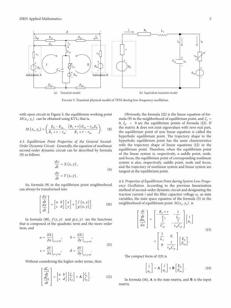
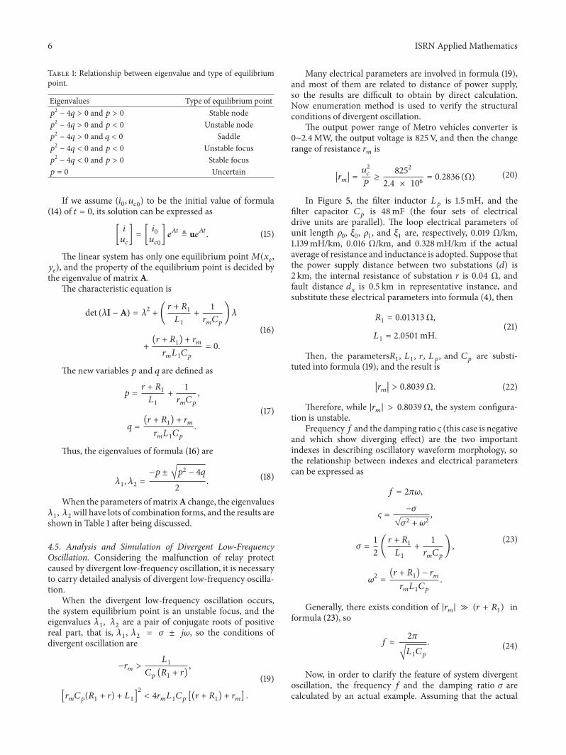


![Homogeneous Solutions of Some Second Order Nonlinear ... · second order nonlinear partial differential equations by applying the base equation method. The author [9] has discussed](https://img.dokumen.tips/doc/110x75/5ecaf52d5fef0574637f1eac/homogeneous-solutions-of-some-second-order-nonlinear-second-order-nonlinear.jpg)