Embed Size (px)
Citation preview

Research ArticleIntegrated Power Flow and Short Circuit CalculationMethod for Distribution Network with Inverter BasedDistributed Generation
Shan Yang1 and Xiangqian Tong12
1School of Automation and Information Engineering Xirsquoan University of Technology Xirsquoan Shaanxi 710048 China2Xirsquoan Hailian Petrochemical Technologies Co Ltd Xirsquoan Shaanxi 710065 China
Correspondence should be addressed to Xiangqian Tong lstongmailxauteducn
Received 27 January 2016 Revised 27 May 2016 Accepted 30 May 2016
Academic Editor Yan-WuWang
Copyright copy 2016 S Yang and X TongThis is an open access article distributed under the Creative Commons Attribution Licensewhich permits unrestricted use distribution and reproduction in any medium provided the original work is properly cited
Power flow calculation and short circuit calculation are the basis of theoretical research for distribution network with inverterbased distributed generation The similarity of equivalent model for inverter based distributed generation during normal andfault conditions of distribution network and the differences between power flow and short circuit calculation are analyzed in thispaperThen an integrated power flow and short circuit calculation method for distribution network with inverter based distributedgeneration is proposedThe proposed method let the inverter based distributed generation be equivalent to 119868120579 bus which makes itsuitable to calculate the power flow of distribution network with a current limited inverter based distributed generation And thelow voltage ride through capability of inverter based distributed generation can be considered as well in this paper Finally sometests of power flow and short circuit current calculation are performed on a 33-bus distribution network The calculated resultsfrom the proposed method in this paper are contrasted with those by the traditional method and the simulation method whoseresults have verified the effectiveness of the integrated method suggested in this paper
1 Introduction
The reserved finiteness and destruction of environment byfossil energy havemade the application of distributed genera-tion (DG) widespread gradually [1] The grid-connected DGin distribution network can reduce the loss of fossil energyand network lines and improve the utilization of energyand the reliability of customers However DG also bringssome unfavorable effects at the same time For examplein normal operation condition of distribution network theelectrical states of distribution network will be changed dueto the random power output from DG And the changedinstalled position and installed capacity of DG may bringsome unfavorable effects on voltage and loss In fault oper-ation condition of distribution network the magnitude anddirection of short circuit current flowing through the linecould be changed too and themisoperation and failure actionof traditional 3-sectional current protection could happen[2 3] Power flow and short circuit calculation are the basisof analyzing the normal and fault conditions of distribution
network respectively Therefore it is important to studythe power flow and short circuit calculation for research ofdistribution network with DG
The DGs in distribution network are mainly divided intogenerator based DG and inverter based DG of which theinverter based DG is applied in distribution network widelysuch as photovoltaic (PV) permanent magnet synchronousgenerator (PMSG) and energy storage system (ESS) There-fore it is significant to study the power flow and short circuitcalculation methods for distribution network with inverterbased DGs As the research focus in this paper the DGmentioned below without additional instruction referred tois expressed as inverter based DG
Both in power flow and in short circuit calculation theresearch at present mainly consists of building equivalentmodel of inverter basedDG and putting forward correspond-ing calculation method Being unlike generator based DGthe output characteristic of inverter based DG is mainlydominated by its control unit In power flow calculationthe equivalent models of DGs under different control are
Hindawi Publishing CorporationMathematical Problems in EngineeringVolume 2016 Article ID 9404951 10 pageshttpdxdoiorg10115520169404951
2 Mathematical Problems in Engineering
different In constant power control the DG should beequivalent to 119875119876 bus while in constant voltage control theDG should be equivalent to PV bus if the reactive poweroutput from DG is within limit If the reactive power outputfrom DG is beyond the limit the DG should be equivalentto 119875119876 bus [4 5] Therefore the equivalent model of inverterbased DG is mainly modeled as 119875119876 bus or PV bus Andfor calculation method backforward sweep method andNewton method are generally used the same as traditionalpower flow calculation [6ndash8]
In short circuit calculation the present fault equivalentmodels of inverter based DG have had the following threeforms (1) At the assumption of constant active and reactivepower output from DG during a fault DG should be equiva-lent to constant powermodel [9] (2)According to the currentlimiting characteristic of inverter DG should enter currentlimiting status during a fault As a result DG can be equiva-lent to constant current source approximately [10 11] (3)Thefault equivalent model of inverter based DG is decided byjudging the current limiting status of DG The DG enteringthe current limiting status is equivalent to constant currentmodel Conversely the DG is equivalent to constant powermodel [12 13] As far as short circuit calculation methodis concerned the superposition theorem which calculatesthe normal component and fault component of distributionnetwork respectively and superposes them [14] is usuallyadopted
From the researches introduced above it can be seenthat in power flow calculation the equivalent model ofinverter based DG is processed ideally The current limitingstatus of inverter based DG has not been considered Forexample DGmay enter into the current limiting status whenthe voltage stability of distribution network is analyzed withpower flow calculation for the loads increasing too muchIn this case the control objectives of inverter cannot bemaintained Hence if the inverter based DG is still modeledas 119875119876 or PV bus the impact of DG on power flow cannotbe correctly included Similarly in short circuit calculationDG may enter into the current limiting status as well forthe decreased voltage at point of common coupling (PCC)during a fault At this moment the inverter based DG shouldbe equivalent to current source which has been mentionedin some researches already But the current source modelsproposed in those researches are ideally for the simplifiedanalysis of current output regulation In addition a lot ofinverter based DGs have been configured with Low VoltageRide Through (LVRT) control at present [15] Therefore thefault equivalent model of inverter based DG under LVRTcontrol should be studied
In this paper the equivalent model of inverter basedDG in normal and fault operation conditions of distributionnetwork and the difference between power flow and shortcircuit calculation are analyzed at first Then an integratedpower flow and short circuit calculation method of distribu-tion network with inverter based DG is proposed accordingto the similarities between equivalent models of inverterbased DG in normal and fault operation conditions Finallythe proposed method is verified in an example It is conve-nient to use the integrated calculation method to calculate
PI
PI
dq
abc
PWM
PI
PI
+
minus
+
+
+
+
+
minus
minus
minus minus
minus
UdcP id Us minus 120596Liq
idref
minus120596Lidiq
iqref
Q
Qref = 0
UdcrefPref
Figure 1 Control block of inverter
power flow or short circuit current in practical engineer-ing
2 Equivalent Model of Inverter Based DG
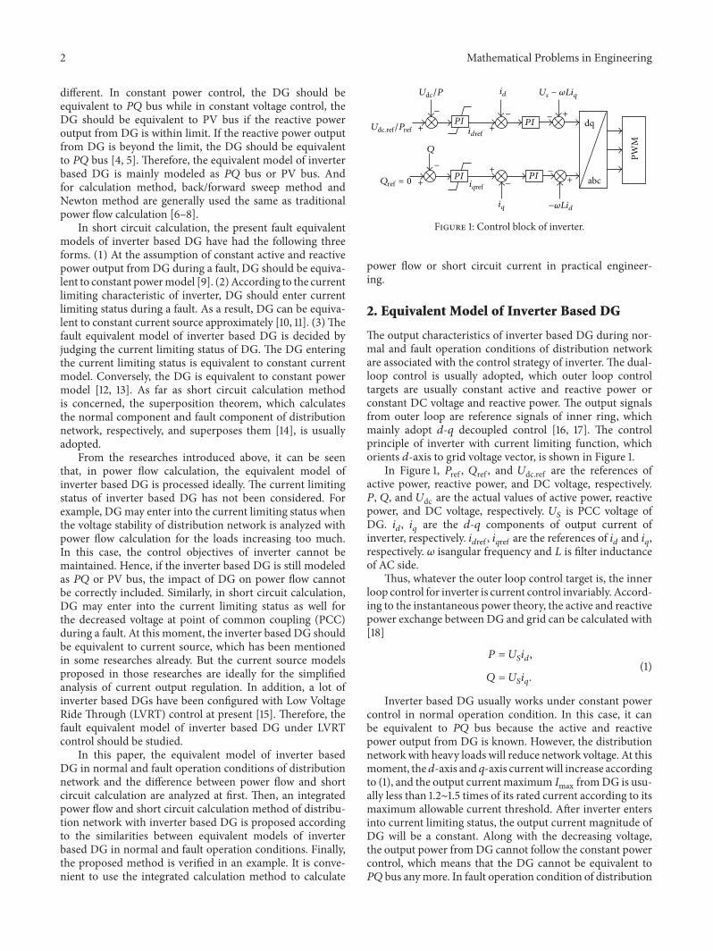
The output characteristics of inverter based DG during nor-mal and fault operation conditions of distribution networkare associated with the control strategy of inverter The dual-loop control is usually adopted which outer loop controltargets are usually constant active and reactive power orconstant DC voltage and reactive power The output signalsfrom outer loop are reference signals of inner ring whichmainly adopt 119889-119902 decoupled control [16 17] The controlprinciple of inverter with current limiting function whichorients 119889-axis to grid voltage vector is shown in Figure 1
In Figure 1 119875ref 119876ref and 119880dcref are the references ofactive power reactive power and DC voltage respectively119875 119876 and 119880dc are the actual values of active power reactivepower and DC voltage respectively 119880
119878
is PCC voltage ofDG 119894
119889
119894119902
are the 119889-119902 components of output current ofinverter respectively 119894
119889ref 119894119902ref are the references of 119894119889 and 119894119902
respectively 120596 isangular frequency and 119871 is filter inductanceof AC side
Thus whatever the outer loop control target is the innerloop control for inverter is current control invariably Accord-ing to the instantaneous power theory the active and reactivepower exchange between DG and grid can be calculated with[18]
119875 = 119880119878
119894119889
119876 = 119880119878
119894119902
(1)
Inverter based DG usually works under constant powercontrol in normal operation condition In this case it canbe equivalent to 119875119876 bus because the active and reactivepower output from DG is known However the distributionnetwork with heavy loads will reduce network voltage At thismoment the119889-axis and 119902-axis currentwill increase accordingto (1) and the output currentmaximum 119868max fromDG is usu-ally less than 12sim15 times of its rated current according to itsmaximum allowable current threshold After inverter entersinto current limiting status the output current magnitude ofDG will be a constant Along with the decreasing voltagethe output power fromDG cannot follow the constant powercontrol which means that the DG cannot be equivalent to119875119876 bus anymore In fault operation condition of distribution
Mathematical Problems in Engineering 3
network the DGmay enter into the current limiting status inthe same way easier due to the decreased PCC voltage causedby fault
After inverter enters into current limiting status themagnitude of output current from DG is 119868max In unit powerfactor control mode the phase difference 120579 between outputcurrent and PCC voltage of DG is 0∘ while in nonunit powerfactor control mode the power factor is given normallywhich means the phase difference 120579 is known AccordinglyDG can be equivalent to 119868120579 bus at current limiting status119868 is 119868max and 120579 is the phase difference between the outputcurrent and PCC voltage of DG Hence the equivalent modelof inverter based DG should be changed from 119875119876 bus to 119868120579
bus when inverter enters the current limiting status in bothpower flow and short circuit calculation
3 The Difference between Short CircuitCalculation and Power Flow Calculation
Through the analysis of equivalent models for inverter basedDG during normal and fault conditions of distributionnetwork it can be seen that the similarity between them isthat DG should be modeled as 119875119876 and 119868120579 buses respectivelybefore and after inverter entering current limiting statusHence an integrated power flow and short circuit calculationmethod is proposed in this paper which takes the idea ofpower flow calculation into short circuit calculation Thismethod can calculate both power flow and short circuitcurrent of distribution network Since the power flow calcu-lation method of this paper is only applicable to symmetricsystem the integrated calculation method based on it isonly applicable to symmetrical fault calculation In additionshort circuit calculation itself is different from power flowcalculation whereby the following two problems have to besolved in short circuit calculation
31 The Modification of Bus Admittance Matrix for Distribu-tion Network In three-phase short circuit calculation thenode admittance matrix should be modified by followingthree reasons
(1) Loads Model The loads of distribution network areomitted in three-phase symmetrical short circuit calculationusually If the impacts of loads on short circuit current haveto be taken into consideration the loads model should bechanged from constant power model to constant impedancemodel This is because the calculation would not convergedue to the unbalanced power flows in downstream distribu-tion network of fault point Then the bus admittance matrixof distribution network should be modified after the loadsmodel is changed The short circuit calculation in this paperhas ignored the loads of distribution network
(2) Grounding Resistance Since fault point only exists in faultcondition of distribution network the circuit structures ofdistribution network during normal and fault conditions aredifferent In fault condition the fault happens in somewhereof distribution network whichmeans that a grounded branchis connecting to the fault point as shown in Figure 2 119911
119891
in
DG
DG
i
i
i + 1
i + 1
i minus 1
i minus 1
Riminus1i Ximinus1i Rii+1 Xii+1
zf
Figure 2 Equivalent circuit of distribution network in fault condi-tion
Figure 2 is grounding resistance (119911119891
= 0 under ideal metallicshort circuit)
From Figure 2 it can be seen that there is a new addedgrounding admittance at fault point 119894 So that in short circuitcalculation the self-admittance of fault point 119894 needs to bemodified according to the following equation
119884119894119894119891
= 119884119894119894119899
+1
119911119891
(2)
where 119884119894119894119891
and 119884119894119894119899
are the self-admittance of bus 119894 ofpostfault and prefault distribution network respectively
(3) DG in Downstream of the Fault Point In distributionnetwork the fault may occur in any position of line Ifthere are multiple DGs in same distribution network theDGs can be divided into two categories which are DGs inupstream of fault point and DGs in downstream of faultpoint In past short circuit calculationmethod of distributionnetwork withDG the short circuit current contribution fromDG in downstream of fault point has not been taken intoaccount generally [19] This is because the power capacityof DG in distribution network is small Hence the DGin downstream of fault point would be disconnected fromdistribution network under low voltage protection Althoughthe DG still connects to distribution network the shortcircuit current from DG is small enough thereby only theshort circuit current contribution from DG in upstream offault point is usually considered
However short circuit current from the DGs in down-stream of fault point is larger if moreDGs are installed in thatarea In addition DG is requested to keep grid-connectionfor a period of time during a faultTherefore the short circuitcurrent contribution from DGs in downstream of fault pointshould not be ignored
For example theDG in Figure 2 is located in downstreamof fault point and an isolated circuit is formed betweenfault point and DG At this moment the output currentfrom DG fails to follow its control target since the outputcharacteristics of DG are only associated with line impedancecharacteristics To simplify the calculation the DG in down-stream of fault point should be regarded as current sourceand modeled as 119868120579 bus with 119868 = 119868max 120579 = 0
∘ Then the
4 Mathematical Problems in Engineering
parameters of the lines between DG and fault point shouldbe updated from complex impedance to impedance modulusvalue 119911 (119911 = radic1199032 + 1199092) And the bus admittance matrix ofdistribution network needs to be modified
32 LVRT Fault Equivalent Model of DG Both in normaland in fault operation conditions of distribution networkthe equivalent model of inverter based DG mentioned aboveis analyzed based on the assumption of DG under constantpower However in order to make full use of reactive powercapacity of inverter when a fault takes place the DG hasusually had the ability of LVRT [20] The fault equivalentmodel of DG with LVRT control is more complex becausethe reactive power outputs from DG and 120579 are variable
It is important to note that the output characteristics ofDG in downstream of fault point are only associated withline impedance characteristics so that the LVRT model canonly be applied to the DG in upstream of fault point In orderto take the short circuit current contribution from DG withLVRT control into consideration it is necessary to analyze theLVRT equivalent model of inverter based DG
Although the LVRT standards of different types ofinverter based DG are different the control idea of themis the same When a fault occurs in distribution networkwhether the DG adopts the LVRT control or not is decided byPCC voltage detected by control system In LVRT control thereactive current reference value of control system is adjustedaccording to the PCC voltageThen the reactive power outputfrom DG can be adjusted too In this paper the LVRT faultequivalent model of DG is described as follows
(1)119880119863119866
ge 09 119901119906 In this situation DG still maintains originalconstant power control and the LVRT control cannot beswitched on The fault equivalent model is
119875DG = 119875DG0
119876DG = 119876DG0(3)
where 119880DG is the PCC voltage of DG 119875DG and 119876DG are theactive power and reactive power output of DG respectivelyand 119875DG0 and119876DG0 are the prefault active and reactive poweroutput of DG
(2) 04 119901119906 lt 119880119863119866
lt 09 119901119906 In this situation the PCC voltageof DG drops below 09 pu and DG starts to output reactivepower current according to expression as follows
119868119902
= 119870 (1 minus 119880DG) 119868119873 (4)
where 119868119873
is the per unit rated current of inverter basedDG119870is the voltage adjustment coefficient of reactive power currentoutput from DG For example 119870 = 2 means the voltagedropped 1 based on 1 pu the reactive power current outputfrom DG increased 2 of rated current With an increasein reactive current output from DG the DG may enter thecurrent limiting status due to themaximumallowable currentthreshold The judgment of current limiting status is the key
toDG converting to 119868120579 bus from119875119876 busThe current limitingstatus can be determined by the following equation
radic(119875DG0119880DG
)
2
+ (119870 (1 minus 119880DG) 119868119873)2
gt 119868max (5)
If (5) is not satisfied the DG is not current limited DGcan still be equivalent to 119875119876 bus The fault equivalent modelis
119875DG = 119875DG0
119876DG = 119868119902
119880DG(6)
If (5) is satisfied the DG is current limited DG should beconverted into 119868120579 bus The fault equivalent model is
119868DG = 119868max
120579DG = arcsin119868119902
119868max
(7)
(3) 119880119863119866
le 04 119901119906 In this situation the PCC voltage ofDG drops below 04 pu In order to support voltage fordistribution network adequately DG should output reactivepower current only At this moment the phase difference 120579between the output current and PCC voltage of DG is 90∘The equivalent model of the DG can be modeled as 119868120579 busdirectly The fault equivalent model is
119868DG = 119868max
120579DG = 90∘
(8)
From the LVRT equivalent model of DG it can be seenthat it is related to the PCC voltage of DG in current limitingstatus and noncurrent limiting status Besides whether theLVRT control is switched on or not the fault equivalentmodels of DG are similar Both the fault equivalent modelscan be modeled as 119875119876 and 119868120579 buses respectively before andafter inverter entering current limiting status Therefore theidea of power flow calculation can be used to short circuitcalculation under LVRT control similarly
4 Integrated Calculation Method
According to the analysis of equivalent model for inverterbased DG during normal and fault operation conditions ofdistribution network it can be seen that DG should havebeen converted into 119868120579 bus in some operation scenariosThe integrated calculation method proposed in this paperuses the idea of power flow calculation to calculate shortcircuit current However the power flow calculation methodin the past cannot calculate the power flow of distributionnetwork with 119868120579 bus directly Hence in this section theconversion condition of bus type is analyzed and the powerflow calculation method of distribution network with 119868120579 busis studied
Mathematical Problems in Engineering 5
41 Switching Condition of Bus Type At the beginning ofcalculation the present status of DG is unknown Thereforeit should be assumed that whenDG keeps the constant powercontrol at present the output current from DG is calculatedaccording to results of past traditional power flow calculationmethod by (9) as follows
119868DG119894 =
1003816100381610038161003816100381610038161003816100381610038161003816
(DG119894
DG119894)
lowast1003816100381610038161003816100381610038161003816100381610038161003816
(9)
where DG119894 is the set value of output complex power fromDGat bus 119894 under 119875119876 control DG119894 is the PCC voltage of DG If119868DG119894 gt 119868max119894 the DG at bus 119894 enters into the current limitingstatus and should be switched to 119868120579 120579 depends on the outputpower factor of DG
42 Power Flow Calculation Method of Distribution Networkwith 119868120579 Bus For 119868120579 bus in distribution network only itsinjected current 119868 and the phase difference 120579 between 119868 andPCC voltage are known It is important to note that DG canbe modeled as 119876119868 bus with 119876
119866119894
= 0 while 120579 = 0∘ and can be
modeled as 119875119868 bus with 119875119866119894
= 0while 120579 = plusmn90∘ But these two
bus types can only be applied to the special cases that 120579 = 0∘
or 120579 = plusmn90∘ In most cases the current limited DG can be
modeled as 119868120579 bus and the bus power equation of 119868120579 bus canbe expressed as
119880119894
119868119894
cos 120579119894
minus 119875119871119894
= 119880119894
sum
119895isin119894
119880119895
(119866119894119895
cos 120575119894119895
+ 119861119894119895
sin 120575119894119895
)
119880119894
119868119894
sin 120579119894
minus 119876119871119894
= 119880119894
sum
119895isin119894
119880119895
(119866119894119895
sin 120575119894119895
minus 119861119894119895
cos 120575119894119895
)
(10)
where 119894 isin 119868120579 bus119880 is the voltage amplitude 120575119894119895
(120575119894
minus120575119895
) is thephase difference between bus 119894 and bus 119895 and 119866
119894119895
and 119861119894119895
arethe real and imaginary component of bus admittance matrix
Let 119899 be the number of buses and 119898 be the number of119875119876 buses hence the number of 119868120579 buses is 119899 minus 119898 minus 1 Thesimultaneous equations of power balance equations for 119875119876and 119868120579 buses are obtained as follows
Δ1198751
(119909) = 119875119866119894
minus 119875119871119894
minus 119880119894
sum
119895isin119894
119880119895
(119866119894119895
cos 120575119894119895
+ 119861119894119895
sin 120575119894119895
)
Δ1198752
(119909) = 119880119894
119868119894
cos 120579119894
minus 119875119871119894
minus 119880119894
sum
119895isin119894
119880119895
(119866119894119895
cos 120575119894119895
+ 119861119894119895
sin 120575119894119895
)
Δ1198761
(119909) = 119876119866119894
minus 119876119871119894
minus 119880119894
sum
119895isin119894
119880119895
(119866119894119895
sin 120575119894119895
minus 119861119894119895
cos 120575119894119895
)
Δ1198762
(119909) = 119880119894
119868119894
sin 120579119894
minus 119876119871119894
minus 119880119894
sum
119895isin119894
119880119895
(119866119894119895
sin 120575119894119895
minus 119861119894119895
cos 120575119894119895
)
(11)
where in Δ1198751
(119909) and Δ1198761
(119909) 119894 isin 1 2 119898 while in Δ1198752
(119909)
and Δ1198762
(119909) 119894 isin 119898 + 1119898 + 2 119899 minus 1 In other wordssubscript 1 represents 119875119876 bus and subscript 2 represents 119868120579bus From (11) it can be seen that there are 2(119899minus1) equationsand the number of unknowns is also 2(119899minus1) including voltageamplitude and phase of each bus except slack bus Thereforethe equations number is equal to the number of unknownsand the power flow calculation of distribution network with119868120579 bus can be solved Equation (11) is a nonlinear equationwhich should be solved so that the commonNewtonmethodis adopted in this paper
The key problem to solving power flow by Newtonmethod is the formation and computation of correctionequations According to solving process of Newton methodthe correction equations are formed as follows
[[[[[
[
Δ1198751
Δ1198752
Δ1198761
Δ1198762
]]]]]
]
= minus
[[[[[
[
11986711
11986712
11987311
11987312
11986721
11986722
11987321
11987322
11987211
11987212
11987111
11987112
11987221
11987222
11987121
11987122
]]]]]
]
[[[[[[[[[[
[
Δ1205751
Δ1205752
Δ1198801
1198801
Δ1198802
1198802
]]]]]]]]]]
]
119869 = [
119867 119873
119872 119871]
(12)
The emphasis for solving the correction equations is theformation of Jacobian matrix 119869 Due to the emerging 119868120579 busin power flow calculation the Jacobian matrix of past powerflow calculation method cannot be used directly From (12)it can be found that the Jacobian matrix is composed of foursubmatrixes which are 119867119872119873 119871 According to the theoryof Newton method the expressions of diagonal elements in119873 and 119871 are different from traditional power flow calculationmethod due to the introduction of 119868120579 bus The specificexpressions are shown as follows
Diagonal elements of119873 are
119873119894119894
=120597Δ119875119894
120597119880119894
119880119894
= minus119880119894
sum
119895isin119894
119895 =119894
119880119895
(119866119894119895
cos 120575119894119895
+ 119861119894119895
sin 120575119894119895
) minus 21198802
119894
119866119894119894
119894 isin 1 2 119898
119873119894119894
=120597Δ119875119894
120597119880119894
119880119894
= 119880119894
119868119894
cos 120579119894
minus 119880119894
sum
119895isin119894
119895 =119894
119880119895
(119866119894119895
cos 120575119894119895
+ 119861119894119895
sin 120575119894119895
)
minus 21198802
119894
119866119894119894
119894 isin 119898 + 1119898 + 2 119899 minus 1
(13)
6 Mathematical Problems in Engineering
Diagonal elements of 119871 are
119871119894119894
=120597Δ119876119894
120597119880119894
119880119894
= minus119880119894
sum
119895isin119894
119895 =119894
119880119895
(119866119894119895
sin 120575119894119895
minus 119861119894119895
cos 120575119894119895
) + 21198802
119894
119861119894119894
119894 isin 1 2 119898
119871119894119894
=120597Δ119876119894
120597119880119894
119880119894
= 119880119894
119868119894
sin 120579119894
minus 119880119894
sum
119895isin119894
119895 =119894
119880119895
(119866119894119895
sin 120575119894119895
minus 119861119894119895
cos 120575119894119895
)
+ 21198802
119894
119861119894119894
119894 isin 119898 + 1119898 + 2 119899 minus 1
(14)
The initial values of voltage amplitude and phase of eachbus should be given respectively after Jacobian matrix 119869 isformed which are 120575
(0)
1
= 120575(0)
2
= 0∘ and 119880
(0)
1
= 119880(0)
2
= 1According to the initial values the error vectors Δ119875(0)
1
Δ119875(0)2
Δ119876(0)
1
and Δ119876(0)
2
can be obtained Then the next voltageamplitude and phase can be calculated according to (15) and(16) as follows
[[[[[[[[[[[[
[
Δ120575(119896)
1
Δ120575(119896)
2
Δ119880(119896)
1
119880(119896)
1
Δ119880(119896)
2
119880(119896)
2
]]]]]]]]]]]]
]
= minus (119869(119896)
)minus1
lowast
[[[[[[
[
Δ119875(119896)
1
Δ119875(119896)
2
Δ119876(119896)
1
Δ119876(119896)
2
]]]]]]
]
(15)
120575(119896+1)
1
= 120575(119896)
1
+ Δ120575(119896)
1
120575(119896+1)
2
= 120575(119896)
2
+ Δ120575(119896)
2
119880(119896+1)
1
= 119880(119896)
1
+ Δ119880(119896)
1
119880(119896+1)
2
= 119880(119896)
2
+ Δ119880(119896)
2
(16)
Then substituting (16) into (15) to continue the iterativecalculation until max |Δ119875(119896)
1
Δ119875(119896)
2
| lt 120576 and max |Δ119876(119896)1
Δ119876(119896)
2
| lt 120576 the voltage amplitude and phase of each bus canbe obtained Moreover the output power of current limitedinverter based DG can be solved by
119875119866119894
= 119880119894
sum
119895isin119894
119880119895
(119866119894119895
cos 120575119894119895
+ 119861119894119895
sin 120575119894119895
) + 119875119871119894
119876119866119894
= 119880119894
sum
119895isin119894
119880119895
(119866119894119895
sin 120575119894119895
minus 119861119894119895
cos 120575119894119895
) + 119876119871119894
119894 isin 119898 + 1119898 + 2 119899 minus 1
(17)
Table 1 PCC voltage and output current of DG
DG no DG1 DG2 DG3 DG4Voltagepu 08612 08448 08573 08198Currentpu 58058 59189 58320 60987
43 Flowchart of Integrated Power Flow and Short CircuitCalculation Method In this paper there are two pointswhich must be noted in the proposed integrated power flowand short circuit calculation method First there are somedifferences between short circuit and power flow calculationso that the bus admittance matrix of distribution networkand the corresponding fault equivalent model of DG shouldbe modified for short circuit calculation Second if there aremultiple DGs in same distribution network the equivalentmodels of the rest of DGs may be affected by the changedvoltage due to the equivalent model of one DG changed from119875119876 bus to 119868120579 bus For this reason the iterative process shouldbe terminated until the equivalent model of each DG doesnot change any more The specific flow chart of integratedpower flow and short circuit calculation method is shown inFigure 3
5 Examples and Analysis
In this paper the numerical calculation is performed on a33-bus distribution network whose rated voltage is 10 kV Itis assumed that the same inverter based DGs are connectedto buses 11 17 28 and 33 respectively as shown in Figure 4whose capacity is 05MWThe per unit rated current of DG is5 pu on the basis of the fact that base power and base voltageare 100 kVA and 10 kV It is assumed that the DGs workunderrated condition with unit power factor mode and theiroutput current maximum 119868max is 12 times of rated currentthat is 6 pu Bus 1 is slack bus whose voltage amplitude is 1 puand voltage phase angle is 0∘Thenpower flow calculation andshort circuit calculation in this test system should be carriedout by using the integrated calculation method proposed inthis paper to verify its effectiveness
51 Power Flow Calculation In order to obtain currentlimiting DG the loads in distribution network should beincreased to 18 times of original value to obtain lower voltagein power flow calculation According to calculation processthe calculation starts with DG equivalent to 119875119876 bus and thecurrent limiting status of DG is estimated The RMS of PCCvoltage and output current of each DG are obtained as shownin Table 1 In this paper all calculation results are expressedin per unit (pu) value
From the calculation results in Table 1 it can be seenthat only DG4 enters current limiting status AccordinglyDG4 cannot maintain constant power output and shouldbe equivalent to 119868120579 bus Then according to the calculationprocess the RMS of PCC voltage and output current of eachDG are obtained by the power flow calculation method with119868120579 bus until the equivalent models of each DG are no longerchangedThe calculation results are shown in Table 2 and thevoltage profile of distribution network is shown in Figure 5
Mathematical Problems in Engineering 7
Yes
Yes
No
No
Yes
No
Power flowcalculation
No
Read data of distribution network
Model DG as PQ bus
Short circuit calculation with LVRT
Modify faultequivalent model of DGin upstream of faultpoint according toLVRT model
No equivalent modelof DG is changed
Output calculation results
Start
Calculate bus voltage and output current fromDG by traditional power flow method
Modify fault equivalent model of DG indownstream of the fault point
Modify fault equivalent modelof current limited DG
Some DG is current limited
Yes
Input fault point
Calculate bus voltage and output current fromDG by power flow method with I120579 bus
Ignore load and modify Y
Build bus admittance matrix Y
Figure 3 Flowchart of integrated calculation method
1 2
3
19
23
4
20
24
5
21
25
6
22
26
7
27
8
28
9
29
10
30
11
31
12
32
13
33
14 15 1617
18DG1 DG2
DG3 DG4
Figure 4 Structure chart of a 33-bus distribution system
In order to verify if the power flow of distributionnetwork with 119868120579 bus can be correctly calculated by theintegrated calculation method proposed in this paper amethod based on calculation results comparison between
Table 2 PCC voltage and output current of DG
DG no DG1 DG2 DG3 DG4Voltagepu 08609 08445 08569 08191Currentpu 58076 59207 58349 60000
integrated calculation method and traditional calculationmethod is adopted Because the 119875119876 values of DG undercurrent limiting status are unknown an inversion methodis used Concretely the 119875119876 values of DG under currentlimiting status and the power flow of distribution networkare calculated by the power flow method with 119868120579 bus firstlyThen the traditional calculation method is used to calculate
8 Mathematical Problems in Engineering
080
085
090
095
100
Volta
ge (p
u)
3 5 7 9 11 13 15 17 19 21 23 25 27 29 31 331Bus number
Figure 5 Voltage profile of distribution network
1 2
3
19
23
4
20
24
5
21
25
6
22
26
7
27
8
28
9
29
10
30
11
31
12
32
13
33
14 15 1617
18DG1 DG2
DG3 DG4
f1 f2f3
Figure 6 Structure chart of a 33-bus distribution system with faultpoints
the power flowwith the calculated119875119876 valuesThe correctnessof proposed integrated method can be verified if the powerflows calculated by two methods are the same In this casethe power flow of distribution network and active poweroutput from current limited DG4 are calculated by integratedmethod at first And the calculated active power output fromDG4 is 49146 pu Then the power flow is again calculatedby traditional power flow calculation method with DG4modeled as 119875119876 bus whose active power is 119875 = 49146 puLastly the maximum absolute value error of voltage of eachbus calculated by two methods is 74884119890 minus 6 So that theproposed integrated method in this paper is correct
52 Short Circuit Calculation for DG without LVRT Con-trol Similarly the short circuit current is calculated bythe integrated calculation method proposed in this paperin the same 33-bus distribution network The three-phasegrounding faults with grounding resistance are 0 which areset on buses 9 18 and 31 respectively as shown in Figure 6The fault positions set in this paper can be divided into thefollowing four cases All DGs in distribution network are inupstream of fault point (f2) some DGs are in downstreamof fault point (f1 and f3) the fault occurs in trunk line (f1and f2) and the fault occurs in branch line (f3) Accordingto the calculating process the DG in upstream of fault pointis equivalent to 119875119876 bus and the DG in downstream of faultpoint is equivalent to 119868120579 bus at first calculation The outputcurrent from DGs is obtained as shown in Table 3
From the calculation results it can be seen that the DGin distribution network is easy to enter current limitingstatus during faults If the DG in upstream of the fault point
Table 3 Short circuit current output from each DG
Output short circuit currentpu Fault pointf1 f2 f3
DG1 6 83929 68759DG2 6 509485 65835DG3 92628 57244 117298DG4 88464 56192 6
Table 4 Short circuit current comparison results between calcula-tion and simulation
Short circuit currentpu Fault pointf1 f2 f3
Calculation 21245 7774 14397Simulation 21079 7754 14398Error100 079 025 0007
Table 5 Part of bus voltage of distribution network
Bus voltagepu Fault pointf1 f2 f3
3 08751 09626 091926 05072 08499 067989 0 06781 0702011 00181 05788 0716614 00371 03524 0730517 00603 00724 0746118 00603 0 0746128 05253 08673 0417331 05387 08801 033 05426 08838 00068
enters the current limiting status its fault equivalent modelshould be converted into 119868120579 bus In this case the outputcurrent from current limited DG is 119868max and 120579 = 0
∘ forthe DG without LVRT control Then the calculation processis continued until the equivalent models of each DG areno longer changed The short circuit currents of f1 f2 andf3 are calculated Moreover the simulation of this exampleis built in MATLABSimulink The calculation results byintegrated calculation method are compared with those bythe simulation method in MATLABSimulink with theirresults shown in Table 4
From the data in Table 4 it can be seen that the resultsbased on the integrated calculation method proposed in thispaper are similar to the simulation results and the errorsbetween them are reasonable whereby the effectiveness andcorrectness of the proposed method are verified Besides thecalculation results of the part of bus voltage of distributionnetwork are shown in Table 5
53 Short Circuit Calculation for DG with LVRT Control Inthis case the DG in upstream of fault point is equivalentto 119875119876 bus and the DG in downstream of fault point isequivalent to 119868120579 bus similarly at first The calculated current
Mathematical Problems in Engineering 9
Table 6 Short circuit current comparison results between calcula-tion and simulation
Short circuit currentpu Fault pointf1 f2 f3
Calculation 211 7742 14480Simulation 21128 7754 14569Error100 013 015 061
Table 7 Part of bus voltage of distribution network
Bus voltagepu Fault pointf1 f2 f3
3 08757 09630 091996 05102 08519 068399 0 06822 0717211 00182 05830 0732014 00371 03539 0747917 00603 00721 0768918 00603 0 0768928 05330 08698 0419931 05507 08829 033 05573 08868 00068
outputs from DGs are the same as those in Table 3 Thenthe current limiting status of DG in upstream of fault pointis judged according to the calculation results Accordingto the LVRT equivalent model the output current and thephase difference between output current and PCC voltageof DGs in current limiting status are calculated and alsothe output active and reactive power of DGs in noncurrentlimiting status are calculated Then the calculation processis continued until the equivalent models of each DG are nolonger changed In this paper the short circuit currents ofthree kinds of fault are calculated according to the integratedcalculationmethodMoreover the simulation of this exampleis built by MATLABSimulink The calculation results byintegrated calculation method are compared with those bythe simulation method in MATLABSimulink with theirresults shown in Table 6
From the data in Table 6 it can be seen that the resultsbased on the integrated calculation method are similar tothe simulation results and the errors between them arereasonable In addition the calculation results of the part ofbus voltage of distribution network are shown in Table 7
From the short circuit calculation results in Tables 5and 7 it can be seen that the bus voltages by short circuitcalculation of DG with LVRT control are bigger than thosewithout LVRT control It is indicated that the LVRT controlhas had an increasing effect upon bus voltage which reflectsits advantage in the case of distribution network fault
6 Conclusion
According to the theoretical analysis and simulation ver-ification for the integrated power flow and short circuit
calculation method of distribution network with inverterbased DG the following conclusions can be obtained
(1) The equivalent models for inverter based DG duringnormal and fault conditions of distribution networkare similar to each other Both equivalent models canbe modeled as 119875119876 and 119868120579 buses respectively beforeand after inverter entering current limiting statusTherefore the power flow and short circuit currentcan be calculated in the same way by an integratedpower flow and short circuit calculation method
(2) If distribution network has 119868120579 bus the expressionsof elements related to 119868120579 bus in Jacobian matrixbeing a part of correction equation for power flowcalculation are different from those by traditionalpower flow calculation The expressions should bereformed according to the power balance equationsof 119868120579 bus Then power flow calculation by solving thecorrection equations can be completed
(3) LVRT control is a conventional control of DG when afault takes place in a distribution network Hence theLVRT equivalent model which is more complicatedthan equivalent model in normal operation condi-tion should be analyzed
(4) The distinction and similarity of power flow calcula-tion and short circuit calculation should be attendedfor using the idea of power flow calculation to cal-culate short circuit current And the adaptive com-plements for short circuit calculation are added inthe process of integrated calculation method Theintegrated power flow and short circuit calculationmethod proposed in this paper can be directly appliedto practical engineering applications
Competing Interests
The authors declare that there is no conflict of interestsregarding the publication of this paper
Acknowledgments
This work has been supported by the National NaturalScience Foundation of China (51507139) the Key DisciplineSpecial Foundation of Shaanxi Province China (5X1301) andtheMajor Scientific and Technological Innovation Projects ofShaanxi Province China (2015ZKC02-01)
References
[1] A Khamis H Shareef E Bizkevelci and T Khatib ldquoA reviewof islanding detection techniques for renewable distributedgeneration systemsrdquoRenewable and Sustainable Energy Reviewsvol 28 pp 483ndash493 2013
[2] P Paliwal N P Patidar and R K Nema ldquoPlanning of grid inte-grated distributed generators a review of technology objectivesand techniquesrdquo Renewable and Sustainable Energy Reviewsvol 40 pp 557ndash570 2014
[3] M A Haj-Ahmed and M S Illindala ldquoThe influence of in-verter-based DGs and their controllers on distribution network
10 Mathematical Problems in Engineering
protectionrdquo in Proceedings of the IEEE Industry ApplicationsSociety Annual Meeting (IAS rsquo13) pp 1ndash9 October 2013
[4] Y Zhu and K Tomsovic ldquoAdaptive power flow method for dis-tribution systemswith dispersed generationrdquo IEEETransactionson Power Delivery vol 17 no 3 pp 822ndash827 2002
[5] S Li ldquoPower flowmodeling to doubly-fed induction generators(DFIGs) under power regulationrdquo IEEE Transactions on PowerSystems vol 28 no 3 pp 3292ndash3301 2013
[6] Y Ju W Wu and B Zhang ldquoConvergence problem in for-wardbackward sweep power flow method caused by non-positive-sequence impedance of distributed generators and itssolutionrdquo International Journal of Electrical Power amp EnergySystems vol 65 pp 463ndash466 2015
[7] P A N Garcia J L R Pereira S Carneiro and V M DaCosta ldquoThree-phase power flow calculations using the currentinjection methodrdquo IEEE Transactions on Power Systems vol 15no 2 pp 508ndash514 2000
[8] H Shateri M Ghorbani N Eskandari and A H Mohammad-Khani ldquoLoad flow method for unbalanced distribution net-works with Dispersed Generation unitsrdquo in Proceedings of the47th International Universities Power Engineering Conference(UPEC rsquo12) pp 1ndash7 September 2012
[9] C Wang and X Sun ldquoAn improved short circuit calculationmethod for distribution network with distributed generationsrdquoAutomation of Electric Power Systems vol 36 no 23 pp 54ndash582012
[10] T N Boutsika and S A Papathanassiou ldquoShort-circuit calcu-lations in networks with distributed generationrdquo Electric PowerSystems Research vol 78 no 7 pp 1181ndash1191 2008
[11] Y Shan T Xiangqian L Jian et al ldquoShort-circuit current cal-culation of distribution network with distributed generationrdquoPower System Technology vol 39 no 7 pp 1977ndash1982 2015
[12] N RajaeiMH AhmedMM Salama andR K Varma ldquoAnal-ysis of fault current contribution from inverter based dis-tributed generationrdquo in Proceedings of the IEEE PES GeneralMeeting ConferenceampExposition pp 1ndash5NationalHarborMdUSA July 2014
[13] C A Plet M Graovac T C Green and R Iravani ldquoFaultresponse of grid-connected inverter dominated networksrdquo inProceedings of the Power and Energy Society General Meetingpp 1ndash8 Minneapolis Minn USA July 2010
[14] N K Gouvalas I F Gonos and I A Stathopulos ldquoImpact studyof short-circuit calculation methods on the design of a windfarmrsquos grounding systemrdquo Renewable Energy vol 66 pp 25ndash322014
[15] A Uphues K Notzold R Wegener and S Soter ldquoSOGI basedgrid fault detection for feeding asymmetrical reactive currentsto fulfill LVRT requirementsrdquo in Proceedings of the IEEEAFRICON pp 1ndash5 Pointe-Aux-Piments Mauritius September2013
[16] W ChenShan L Yan and P Ke ldquoOverview of typical controlmethods for grid-connected inverters of distributed genera-tionrdquo Proceedings of the CSU-EPSA vol 24 no 2 pp 12ndash202012
[17] R Teodorescu F Blaabjerg M Liserre and P C Loh ldquoPro-portional-resonant controllers and filters for grid-connectedvoltage-source convertersrdquo IEE Proceedings Electric PowerApplications vol 153 no 5 pp 750ndash762 2006
[18] A Ovalle G Ramos S Bacha A Hably and A RumeauldquoDecentralized control of voltage source converters in micro-grids based on the application of instantaneous power theoryrdquo
IEEE Transactions on Industrial Electronics vol 62 no 2 pp1152ndash1162 2015
[19] I Tristiu C Bulac S Costinas L Toma A Mandis and TZabava ldquoA new and efficient algorithm for short-circuit cal-culation in distribution networks with distributed generationrdquoin Proceedings of the 9th International Symposium on AdvancedTopics in Electrical Engineering (ATEE rsquo15) pp 816ndash821 IEEEBucharest Romania May 2015
[20] C-T Lee C-W Hsu and P-T Cheng ldquoA low-voltage ride-through technique for grid-connected converters of distributedenergy resourcesrdquo IEEE Transactions on Industry Applicationsvol 47 no 4 pp 1821ndash1832 2011
Submit your manuscripts athttpwwwhindawicom
Hindawi Publishing Corporationhttpwwwhindawicom Volume 2014
MathematicsJournal of
Hindawi Publishing Corporationhttpwwwhindawicom Volume 2014
Mathematical Problems in Engineering
Hindawi Publishing Corporationhttpwwwhindawicom
Differential EquationsInternational Journal of
Volume 2014
Applied MathematicsJournal of
Hindawi Publishing Corporationhttpwwwhindawicom Volume 2014
Probability and StatisticsHindawi Publishing Corporationhttpwwwhindawicom Volume 2014
Journal of
Hindawi Publishing Corporationhttpwwwhindawicom Volume 2014
Mathematical PhysicsAdvances in
Complex AnalysisJournal of
Hindawi Publishing Corporationhttpwwwhindawicom Volume 2014
OptimizationJournal of
Hindawi Publishing Corporationhttpwwwhindawicom Volume 2014
CombinatoricsHindawi Publishing Corporationhttpwwwhindawicom Volume 2014
International Journal of
Hindawi Publishing Corporationhttpwwwhindawicom Volume 2014
Operations ResearchAdvances in
Journal of
Hindawi Publishing Corporationhttpwwwhindawicom Volume 2014
Function Spaces
Abstract and Applied AnalysisHindawi Publishing Corporationhttpwwwhindawicom Volume 2014
International Journal of Mathematics and Mathematical Sciences
Hindawi Publishing Corporationhttpwwwhindawicom Volume 2014
The Scientific World JournalHindawi Publishing Corporation httpwwwhindawicom Volume 2014
Hindawi Publishing Corporationhttpwwwhindawicom Volume 2014
Algebra
Discrete Dynamics in Nature and Society
Hindawi Publishing Corporationhttpwwwhindawicom Volume 2014
Hindawi Publishing Corporationhttpwwwhindawicom Volume 2014
Decision SciencesAdvances in
Discrete MathematicsJournal of
Hindawi Publishing Corporationhttpwwwhindawicom
Volume 2014 Hindawi Publishing Corporationhttpwwwhindawicom Volume 2014
Stochastic AnalysisInternational Journal of
2 Mathematical Problems in Engineering
different In constant power control the DG should beequivalent to 119875119876 bus while in constant voltage control theDG should be equivalent to PV bus if the reactive poweroutput from DG is within limit If the reactive power outputfrom DG is beyond the limit the DG should be equivalentto 119875119876 bus [4 5] Therefore the equivalent model of inverterbased DG is mainly modeled as 119875119876 bus or PV bus Andfor calculation method backforward sweep method andNewton method are generally used the same as traditionalpower flow calculation [6ndash8]
In short circuit calculation the present fault equivalentmodels of inverter based DG have had the following threeforms (1) At the assumption of constant active and reactivepower output from DG during a fault DG should be equiva-lent to constant powermodel [9] (2)According to the currentlimiting characteristic of inverter DG should enter currentlimiting status during a fault As a result DG can be equiva-lent to constant current source approximately [10 11] (3)Thefault equivalent model of inverter based DG is decided byjudging the current limiting status of DG The DG enteringthe current limiting status is equivalent to constant currentmodel Conversely the DG is equivalent to constant powermodel [12 13] As far as short circuit calculation methodis concerned the superposition theorem which calculatesthe normal component and fault component of distributionnetwork respectively and superposes them [14] is usuallyadopted
From the researches introduced above it can be seenthat in power flow calculation the equivalent model ofinverter based DG is processed ideally The current limitingstatus of inverter based DG has not been considered Forexample DGmay enter into the current limiting status whenthe voltage stability of distribution network is analyzed withpower flow calculation for the loads increasing too muchIn this case the control objectives of inverter cannot bemaintained Hence if the inverter based DG is still modeledas 119875119876 or PV bus the impact of DG on power flow cannotbe correctly included Similarly in short circuit calculationDG may enter into the current limiting status as well forthe decreased voltage at point of common coupling (PCC)during a fault At this moment the inverter based DG shouldbe equivalent to current source which has been mentionedin some researches already But the current source modelsproposed in those researches are ideally for the simplifiedanalysis of current output regulation In addition a lot ofinverter based DGs have been configured with Low VoltageRide Through (LVRT) control at present [15] Therefore thefault equivalent model of inverter based DG under LVRTcontrol should be studied
In this paper the equivalent model of inverter basedDG in normal and fault operation conditions of distributionnetwork and the difference between power flow and shortcircuit calculation are analyzed at first Then an integratedpower flow and short circuit calculation method of distribu-tion network with inverter based DG is proposed accordingto the similarities between equivalent models of inverterbased DG in normal and fault operation conditions Finallythe proposed method is verified in an example It is conve-nient to use the integrated calculation method to calculate
PI
PI
dq
abc
PWM
PI
PI
+
minus
+
+
+
+
+
minus
minus
minus minus
minus
UdcP id Us minus 120596Liq
idref
minus120596Lidiq
iqref
Q
Qref = 0
UdcrefPref
Figure 1 Control block of inverter
power flow or short circuit current in practical engineer-ing
2 Equivalent Model of Inverter Based DG
The output characteristics of inverter based DG during nor-mal and fault operation conditions of distribution networkare associated with the control strategy of inverter The dual-loop control is usually adopted which outer loop controltargets are usually constant active and reactive power orconstant DC voltage and reactive power The output signalsfrom outer loop are reference signals of inner ring whichmainly adopt 119889-119902 decoupled control [16 17] The controlprinciple of inverter with current limiting function whichorients 119889-axis to grid voltage vector is shown in Figure 1
In Figure 1 119875ref 119876ref and 119880dcref are the references ofactive power reactive power and DC voltage respectively119875 119876 and 119880dc are the actual values of active power reactivepower and DC voltage respectively 119880
119878
is PCC voltage ofDG 119894
119889
119894119902
are the 119889-119902 components of output current ofinverter respectively 119894
119889ref 119894119902ref are the references of 119894119889 and 119894119902
respectively 120596 isangular frequency and 119871 is filter inductanceof AC side
Thus whatever the outer loop control target is the innerloop control for inverter is current control invariably Accord-ing to the instantaneous power theory the active and reactivepower exchange between DG and grid can be calculated with[18]
119875 = 119880119878
119894119889
119876 = 119880119878
119894119902
(1)
Inverter based DG usually works under constant powercontrol in normal operation condition In this case it canbe equivalent to 119875119876 bus because the active and reactivepower output from DG is known However the distributionnetwork with heavy loads will reduce network voltage At thismoment the119889-axis and 119902-axis currentwill increase accordingto (1) and the output currentmaximum 119868max fromDG is usu-ally less than 12sim15 times of its rated current according to itsmaximum allowable current threshold After inverter entersinto current limiting status the output current magnitude ofDG will be a constant Along with the decreasing voltagethe output power fromDG cannot follow the constant powercontrol which means that the DG cannot be equivalent to119875119876 bus anymore In fault operation condition of distribution
Mathematical Problems in Engineering 3
network the DGmay enter into the current limiting status inthe same way easier due to the decreased PCC voltage causedby fault
After inverter enters into current limiting status themagnitude of output current from DG is 119868max In unit powerfactor control mode the phase difference 120579 between outputcurrent and PCC voltage of DG is 0∘ while in nonunit powerfactor control mode the power factor is given normallywhich means the phase difference 120579 is known AccordinglyDG can be equivalent to 119868120579 bus at current limiting status119868 is 119868max and 120579 is the phase difference between the outputcurrent and PCC voltage of DG Hence the equivalent modelof inverter based DG should be changed from 119875119876 bus to 119868120579
bus when inverter enters the current limiting status in bothpower flow and short circuit calculation
3 The Difference between Short CircuitCalculation and Power Flow Calculation
Through the analysis of equivalent models for inverter basedDG during normal and fault conditions of distributionnetwork it can be seen that the similarity between them isthat DG should be modeled as 119875119876 and 119868120579 buses respectivelybefore and after inverter entering current limiting statusHence an integrated power flow and short circuit calculationmethod is proposed in this paper which takes the idea ofpower flow calculation into short circuit calculation Thismethod can calculate both power flow and short circuitcurrent of distribution network Since the power flow calcu-lation method of this paper is only applicable to symmetricsystem the integrated calculation method based on it isonly applicable to symmetrical fault calculation In additionshort circuit calculation itself is different from power flowcalculation whereby the following two problems have to besolved in short circuit calculation
31 The Modification of Bus Admittance Matrix for Distribu-tion Network In three-phase short circuit calculation thenode admittance matrix should be modified by followingthree reasons
(1) Loads Model The loads of distribution network areomitted in three-phase symmetrical short circuit calculationusually If the impacts of loads on short circuit current haveto be taken into consideration the loads model should bechanged from constant power model to constant impedancemodel This is because the calculation would not convergedue to the unbalanced power flows in downstream distribu-tion network of fault point Then the bus admittance matrixof distribution network should be modified after the loadsmodel is changed The short circuit calculation in this paperhas ignored the loads of distribution network
(2) Grounding Resistance Since fault point only exists in faultcondition of distribution network the circuit structures ofdistribution network during normal and fault conditions aredifferent In fault condition the fault happens in somewhereof distribution network whichmeans that a grounded branchis connecting to the fault point as shown in Figure 2 119911
119891
in
DG
DG
i
i
i + 1
i + 1
i minus 1
i minus 1
Riminus1i Ximinus1i Rii+1 Xii+1
zf
Figure 2 Equivalent circuit of distribution network in fault condi-tion
Figure 2 is grounding resistance (119911119891
= 0 under ideal metallicshort circuit)
From Figure 2 it can be seen that there is a new addedgrounding admittance at fault point 119894 So that in short circuitcalculation the self-admittance of fault point 119894 needs to bemodified according to the following equation
119884119894119894119891
= 119884119894119894119899
+1
119911119891
(2)
where 119884119894119894119891
and 119884119894119894119899
are the self-admittance of bus 119894 ofpostfault and prefault distribution network respectively
(3) DG in Downstream of the Fault Point In distributionnetwork the fault may occur in any position of line Ifthere are multiple DGs in same distribution network theDGs can be divided into two categories which are DGs inupstream of fault point and DGs in downstream of faultpoint In past short circuit calculationmethod of distributionnetwork withDG the short circuit current contribution fromDG in downstream of fault point has not been taken intoaccount generally [19] This is because the power capacityof DG in distribution network is small Hence the DGin downstream of fault point would be disconnected fromdistribution network under low voltage protection Althoughthe DG still connects to distribution network the shortcircuit current from DG is small enough thereby only theshort circuit current contribution from DG in upstream offault point is usually considered
However short circuit current from the DGs in down-stream of fault point is larger if moreDGs are installed in thatarea In addition DG is requested to keep grid-connectionfor a period of time during a faultTherefore the short circuitcurrent contribution from DGs in downstream of fault pointshould not be ignored
For example theDG in Figure 2 is located in downstreamof fault point and an isolated circuit is formed betweenfault point and DG At this moment the output currentfrom DG fails to follow its control target since the outputcharacteristics of DG are only associated with line impedancecharacteristics To simplify the calculation the DG in down-stream of fault point should be regarded as current sourceand modeled as 119868120579 bus with 119868 = 119868max 120579 = 0
∘ Then the
4 Mathematical Problems in Engineering
parameters of the lines between DG and fault point shouldbe updated from complex impedance to impedance modulusvalue 119911 (119911 = radic1199032 + 1199092) And the bus admittance matrix ofdistribution network needs to be modified
32 LVRT Fault Equivalent Model of DG Both in normaland in fault operation conditions of distribution networkthe equivalent model of inverter based DG mentioned aboveis analyzed based on the assumption of DG under constantpower However in order to make full use of reactive powercapacity of inverter when a fault takes place the DG hasusually had the ability of LVRT [20] The fault equivalentmodel of DG with LVRT control is more complex becausethe reactive power outputs from DG and 120579 are variable
It is important to note that the output characteristics ofDG in downstream of fault point are only associated withline impedance characteristics so that the LVRT model canonly be applied to the DG in upstream of fault point In orderto take the short circuit current contribution from DG withLVRT control into consideration it is necessary to analyze theLVRT equivalent model of inverter based DG
Although the LVRT standards of different types ofinverter based DG are different the control idea of themis the same When a fault occurs in distribution networkwhether the DG adopts the LVRT control or not is decided byPCC voltage detected by control system In LVRT control thereactive current reference value of control system is adjustedaccording to the PCC voltageThen the reactive power outputfrom DG can be adjusted too In this paper the LVRT faultequivalent model of DG is described as follows
(1)119880119863119866
ge 09 119901119906 In this situation DG still maintains originalconstant power control and the LVRT control cannot beswitched on The fault equivalent model is
119875DG = 119875DG0
119876DG = 119876DG0(3)
where 119880DG is the PCC voltage of DG 119875DG and 119876DG are theactive power and reactive power output of DG respectivelyand 119875DG0 and119876DG0 are the prefault active and reactive poweroutput of DG
(2) 04 119901119906 lt 119880119863119866
lt 09 119901119906 In this situation the PCC voltageof DG drops below 09 pu and DG starts to output reactivepower current according to expression as follows
119868119902
= 119870 (1 minus 119880DG) 119868119873 (4)
where 119868119873
is the per unit rated current of inverter basedDG119870is the voltage adjustment coefficient of reactive power currentoutput from DG For example 119870 = 2 means the voltagedropped 1 based on 1 pu the reactive power current outputfrom DG increased 2 of rated current With an increasein reactive current output from DG the DG may enter thecurrent limiting status due to themaximumallowable currentthreshold The judgment of current limiting status is the key
toDG converting to 119868120579 bus from119875119876 busThe current limitingstatus can be determined by the following equation
radic(119875DG0119880DG
)
2
+ (119870 (1 minus 119880DG) 119868119873)2
gt 119868max (5)
If (5) is not satisfied the DG is not current limited DGcan still be equivalent to 119875119876 bus The fault equivalent modelis
119875DG = 119875DG0
119876DG = 119868119902
119880DG(6)
If (5) is satisfied the DG is current limited DG should beconverted into 119868120579 bus The fault equivalent model is
119868DG = 119868max
120579DG = arcsin119868119902
119868max
(7)
(3) 119880119863119866
le 04 119901119906 In this situation the PCC voltage ofDG drops below 04 pu In order to support voltage fordistribution network adequately DG should output reactivepower current only At this moment the phase difference 120579between the output current and PCC voltage of DG is 90∘The equivalent model of the DG can be modeled as 119868120579 busdirectly The fault equivalent model is
119868DG = 119868max
120579DG = 90∘
(8)
From the LVRT equivalent model of DG it can be seenthat it is related to the PCC voltage of DG in current limitingstatus and noncurrent limiting status Besides whether theLVRT control is switched on or not the fault equivalentmodels of DG are similar Both the fault equivalent modelscan be modeled as 119875119876 and 119868120579 buses respectively before andafter inverter entering current limiting status Therefore theidea of power flow calculation can be used to short circuitcalculation under LVRT control similarly
4 Integrated Calculation Method
According to the analysis of equivalent model for inverterbased DG during normal and fault operation conditions ofdistribution network it can be seen that DG should havebeen converted into 119868120579 bus in some operation scenariosThe integrated calculation method proposed in this paperuses the idea of power flow calculation to calculate shortcircuit current However the power flow calculation methodin the past cannot calculate the power flow of distributionnetwork with 119868120579 bus directly Hence in this section theconversion condition of bus type is analyzed and the powerflow calculation method of distribution network with 119868120579 busis studied
Mathematical Problems in Engineering 5
41 Switching Condition of Bus Type At the beginning ofcalculation the present status of DG is unknown Thereforeit should be assumed that whenDG keeps the constant powercontrol at present the output current from DG is calculatedaccording to results of past traditional power flow calculationmethod by (9) as follows
119868DG119894 =
1003816100381610038161003816100381610038161003816100381610038161003816
(DG119894
DG119894)
lowast1003816100381610038161003816100381610038161003816100381610038161003816
(9)
where DG119894 is the set value of output complex power fromDGat bus 119894 under 119875119876 control DG119894 is the PCC voltage of DG If119868DG119894 gt 119868max119894 the DG at bus 119894 enters into the current limitingstatus and should be switched to 119868120579 120579 depends on the outputpower factor of DG
42 Power Flow Calculation Method of Distribution Networkwith 119868120579 Bus For 119868120579 bus in distribution network only itsinjected current 119868 and the phase difference 120579 between 119868 andPCC voltage are known It is important to note that DG canbe modeled as 119876119868 bus with 119876
119866119894
= 0 while 120579 = 0∘ and can be
modeled as 119875119868 bus with 119875119866119894
= 0while 120579 = plusmn90∘ But these two
bus types can only be applied to the special cases that 120579 = 0∘
or 120579 = plusmn90∘ In most cases the current limited DG can be
modeled as 119868120579 bus and the bus power equation of 119868120579 bus canbe expressed as
119880119894
119868119894
cos 120579119894
minus 119875119871119894
= 119880119894
sum
119895isin119894
119880119895
(119866119894119895
cos 120575119894119895
+ 119861119894119895
sin 120575119894119895
)
119880119894
119868119894
sin 120579119894
minus 119876119871119894
= 119880119894
sum
119895isin119894
119880119895
(119866119894119895
sin 120575119894119895
minus 119861119894119895
cos 120575119894119895
)
(10)
where 119894 isin 119868120579 bus119880 is the voltage amplitude 120575119894119895
(120575119894
minus120575119895
) is thephase difference between bus 119894 and bus 119895 and 119866
119894119895
and 119861119894119895
arethe real and imaginary component of bus admittance matrix
Let 119899 be the number of buses and 119898 be the number of119875119876 buses hence the number of 119868120579 buses is 119899 minus 119898 minus 1 Thesimultaneous equations of power balance equations for 119875119876and 119868120579 buses are obtained as follows
Δ1198751
(119909) = 119875119866119894
minus 119875119871119894
minus 119880119894
sum
119895isin119894
119880119895
(119866119894119895
cos 120575119894119895
+ 119861119894119895
sin 120575119894119895
)
Δ1198752
(119909) = 119880119894
119868119894
cos 120579119894
minus 119875119871119894
minus 119880119894
sum
119895isin119894
119880119895
(119866119894119895
cos 120575119894119895
+ 119861119894119895
sin 120575119894119895
)
Δ1198761
(119909) = 119876119866119894
minus 119876119871119894
minus 119880119894
sum
119895isin119894
119880119895
(119866119894119895
sin 120575119894119895
minus 119861119894119895
cos 120575119894119895
)
Δ1198762
(119909) = 119880119894
119868119894
sin 120579119894
minus 119876119871119894
minus 119880119894
sum
119895isin119894
119880119895
(119866119894119895
sin 120575119894119895
minus 119861119894119895
cos 120575119894119895
)
(11)
where in Δ1198751
(119909) and Δ1198761
(119909) 119894 isin 1 2 119898 while in Δ1198752
(119909)
and Δ1198762
(119909) 119894 isin 119898 + 1119898 + 2 119899 minus 1 In other wordssubscript 1 represents 119875119876 bus and subscript 2 represents 119868120579bus From (11) it can be seen that there are 2(119899minus1) equationsand the number of unknowns is also 2(119899minus1) including voltageamplitude and phase of each bus except slack bus Thereforethe equations number is equal to the number of unknownsand the power flow calculation of distribution network with119868120579 bus can be solved Equation (11) is a nonlinear equationwhich should be solved so that the commonNewtonmethodis adopted in this paper
The key problem to solving power flow by Newtonmethod is the formation and computation of correctionequations According to solving process of Newton methodthe correction equations are formed as follows
[[[[[
[
Δ1198751
Δ1198752
Δ1198761
Δ1198762
]]]]]
]
= minus
[[[[[
[
11986711
11986712
11987311
11987312
11986721
11986722
11987321
11987322
11987211
11987212
11987111
11987112
11987221
11987222
11987121
11987122
]]]]]
]
[[[[[[[[[[
[
Δ1205751
Δ1205752
Δ1198801
1198801
Δ1198802
1198802
]]]]]]]]]]
]
119869 = [
119867 119873
119872 119871]
(12)
The emphasis for solving the correction equations is theformation of Jacobian matrix 119869 Due to the emerging 119868120579 busin power flow calculation the Jacobian matrix of past powerflow calculation method cannot be used directly From (12)it can be found that the Jacobian matrix is composed of foursubmatrixes which are 119867119872119873 119871 According to the theoryof Newton method the expressions of diagonal elements in119873 and 119871 are different from traditional power flow calculationmethod due to the introduction of 119868120579 bus The specificexpressions are shown as follows
Diagonal elements of119873 are
119873119894119894
=120597Δ119875119894
120597119880119894
119880119894
= minus119880119894
sum
119895isin119894
119895 =119894
119880119895
(119866119894119895
cos 120575119894119895
+ 119861119894119895
sin 120575119894119895
) minus 21198802
119894
119866119894119894
119894 isin 1 2 119898
119873119894119894
=120597Δ119875119894
120597119880119894
119880119894
= 119880119894
119868119894
cos 120579119894
minus 119880119894
sum
119895isin119894
119895 =119894
119880119895
(119866119894119895
cos 120575119894119895
+ 119861119894119895
sin 120575119894119895
)
minus 21198802
119894
119866119894119894
119894 isin 119898 + 1119898 + 2 119899 minus 1
(13)
6 Mathematical Problems in Engineering
Diagonal elements of 119871 are
119871119894119894
=120597Δ119876119894
120597119880119894
119880119894
= minus119880119894
sum
119895isin119894
119895 =119894
119880119895
(119866119894119895
sin 120575119894119895
minus 119861119894119895
cos 120575119894119895
) + 21198802
119894
119861119894119894
119894 isin 1 2 119898
119871119894119894
=120597Δ119876119894
120597119880119894
119880119894
= 119880119894
119868119894
sin 120579119894
minus 119880119894
sum
119895isin119894
119895 =119894
119880119895
(119866119894119895
sin 120575119894119895
minus 119861119894119895
cos 120575119894119895
)
+ 21198802
119894
119861119894119894
119894 isin 119898 + 1119898 + 2 119899 minus 1
(14)
The initial values of voltage amplitude and phase of eachbus should be given respectively after Jacobian matrix 119869 isformed which are 120575
(0)
1
= 120575(0)
2
= 0∘ and 119880
(0)
1
= 119880(0)
2
= 1According to the initial values the error vectors Δ119875(0)
1
Δ119875(0)2
Δ119876(0)
1
and Δ119876(0)
2
can be obtained Then the next voltageamplitude and phase can be calculated according to (15) and(16) as follows
[[[[[[[[[[[[
[
Δ120575(119896)
1
Δ120575(119896)
2
Δ119880(119896)
1
119880(119896)
1
Δ119880(119896)
2
119880(119896)
2
]]]]]]]]]]]]
]
= minus (119869(119896)
)minus1
lowast
[[[[[[
[
Δ119875(119896)
1
Δ119875(119896)
2
Δ119876(119896)
1
Δ119876(119896)
2
]]]]]]
]
(15)
120575(119896+1)
1
= 120575(119896)
1
+ Δ120575(119896)
1
120575(119896+1)
2
= 120575(119896)
2
+ Δ120575(119896)
2
119880(119896+1)
1
= 119880(119896)
1
+ Δ119880(119896)
1
119880(119896+1)
2
= 119880(119896)
2
+ Δ119880(119896)
2
(16)
Then substituting (16) into (15) to continue the iterativecalculation until max |Δ119875(119896)
1
Δ119875(119896)
2
| lt 120576 and max |Δ119876(119896)1
Δ119876(119896)
2
| lt 120576 the voltage amplitude and phase of each bus canbe obtained Moreover the output power of current limitedinverter based DG can be solved by
119875119866119894
= 119880119894
sum
119895isin119894
119880119895
(119866119894119895
cos 120575119894119895
+ 119861119894119895
sin 120575119894119895
) + 119875119871119894
119876119866119894
= 119880119894
sum
119895isin119894
119880119895
(119866119894119895
sin 120575119894119895
minus 119861119894119895
cos 120575119894119895
) + 119876119871119894
119894 isin 119898 + 1119898 + 2 119899 minus 1
(17)
Table 1 PCC voltage and output current of DG
DG no DG1 DG2 DG3 DG4Voltagepu 08612 08448 08573 08198Currentpu 58058 59189 58320 60987
43 Flowchart of Integrated Power Flow and Short CircuitCalculation Method In this paper there are two pointswhich must be noted in the proposed integrated power flowand short circuit calculation method First there are somedifferences between short circuit and power flow calculationso that the bus admittance matrix of distribution networkand the corresponding fault equivalent model of DG shouldbe modified for short circuit calculation Second if there aremultiple DGs in same distribution network the equivalentmodels of the rest of DGs may be affected by the changedvoltage due to the equivalent model of one DG changed from119875119876 bus to 119868120579 bus For this reason the iterative process shouldbe terminated until the equivalent model of each DG doesnot change any more The specific flow chart of integratedpower flow and short circuit calculation method is shown inFigure 3
5 Examples and Analysis
In this paper the numerical calculation is performed on a33-bus distribution network whose rated voltage is 10 kV Itis assumed that the same inverter based DGs are connectedto buses 11 17 28 and 33 respectively as shown in Figure 4whose capacity is 05MWThe per unit rated current of DG is5 pu on the basis of the fact that base power and base voltageare 100 kVA and 10 kV It is assumed that the DGs workunderrated condition with unit power factor mode and theiroutput current maximum 119868max is 12 times of rated currentthat is 6 pu Bus 1 is slack bus whose voltage amplitude is 1 puand voltage phase angle is 0∘Thenpower flow calculation andshort circuit calculation in this test system should be carriedout by using the integrated calculation method proposed inthis paper to verify its effectiveness
51 Power Flow Calculation In order to obtain currentlimiting DG the loads in distribution network should beincreased to 18 times of original value to obtain lower voltagein power flow calculation According to calculation processthe calculation starts with DG equivalent to 119875119876 bus and thecurrent limiting status of DG is estimated The RMS of PCCvoltage and output current of each DG are obtained as shownin Table 1 In this paper all calculation results are expressedin per unit (pu) value
From the calculation results in Table 1 it can be seenthat only DG4 enters current limiting status AccordinglyDG4 cannot maintain constant power output and shouldbe equivalent to 119868120579 bus Then according to the calculationprocess the RMS of PCC voltage and output current of eachDG are obtained by the power flow calculation method with119868120579 bus until the equivalent models of each DG are no longerchangedThe calculation results are shown in Table 2 and thevoltage profile of distribution network is shown in Figure 5
Mathematical Problems in Engineering 7
Yes
Yes
No
No
Yes
No
Power flowcalculation
No
Read data of distribution network
Model DG as PQ bus
Short circuit calculation with LVRT
Modify faultequivalent model of DGin upstream of faultpoint according toLVRT model
No equivalent modelof DG is changed
Output calculation results
Start
Calculate bus voltage and output current fromDG by traditional power flow method
Modify fault equivalent model of DG indownstream of the fault point
Modify fault equivalent modelof current limited DG
Some DG is current limited
Yes
Input fault point
Calculate bus voltage and output current fromDG by power flow method with I120579 bus
Ignore load and modify Y
Build bus admittance matrix Y
Figure 3 Flowchart of integrated calculation method
1 2
3
19
23
4
20
24
5
21
25
6
22
26
7
27
8
28
9
29
10
30
11
31
12
32
13
33
14 15 1617
18DG1 DG2
DG3 DG4
Figure 4 Structure chart of a 33-bus distribution system
In order to verify if the power flow of distributionnetwork with 119868120579 bus can be correctly calculated by theintegrated calculation method proposed in this paper amethod based on calculation results comparison between
Table 2 PCC voltage and output current of DG
DG no DG1 DG2 DG3 DG4Voltagepu 08609 08445 08569 08191Currentpu 58076 59207 58349 60000
integrated calculation method and traditional calculationmethod is adopted Because the 119875119876 values of DG undercurrent limiting status are unknown an inversion methodis used Concretely the 119875119876 values of DG under currentlimiting status and the power flow of distribution networkare calculated by the power flow method with 119868120579 bus firstlyThen the traditional calculation method is used to calculate
8 Mathematical Problems in Engineering
080
085
090
095
100
Volta
ge (p
u)
3 5 7 9 11 13 15 17 19 21 23 25 27 29 31 331Bus number
Figure 5 Voltage profile of distribution network
1 2
3
19
23
4
20
24
5
21
25
6
22
26
7
27
8
28
9
29
10
30
11
31
12
32
13
33
14 15 1617
18DG1 DG2
DG3 DG4
f1 f2f3
Figure 6 Structure chart of a 33-bus distribution system with faultpoints
the power flowwith the calculated119875119876 valuesThe correctnessof proposed integrated method can be verified if the powerflows calculated by two methods are the same In this casethe power flow of distribution network and active poweroutput from current limited DG4 are calculated by integratedmethod at first And the calculated active power output fromDG4 is 49146 pu Then the power flow is again calculatedby traditional power flow calculation method with DG4modeled as 119875119876 bus whose active power is 119875 = 49146 puLastly the maximum absolute value error of voltage of eachbus calculated by two methods is 74884119890 minus 6 So that theproposed integrated method in this paper is correct
52 Short Circuit Calculation for DG without LVRT Con-trol Similarly the short circuit current is calculated bythe integrated calculation method proposed in this paperin the same 33-bus distribution network The three-phasegrounding faults with grounding resistance are 0 which areset on buses 9 18 and 31 respectively as shown in Figure 6The fault positions set in this paper can be divided into thefollowing four cases All DGs in distribution network are inupstream of fault point (f2) some DGs are in downstreamof fault point (f1 and f3) the fault occurs in trunk line (f1and f2) and the fault occurs in branch line (f3) Accordingto the calculating process the DG in upstream of fault pointis equivalent to 119875119876 bus and the DG in downstream of faultpoint is equivalent to 119868120579 bus at first calculation The outputcurrent from DGs is obtained as shown in Table 3
From the calculation results it can be seen that the DGin distribution network is easy to enter current limitingstatus during faults If the DG in upstream of the fault point
Table 3 Short circuit current output from each DG
Output short circuit currentpu Fault pointf1 f2 f3
DG1 6 83929 68759DG2 6 509485 65835DG3 92628 57244 117298DG4 88464 56192 6
Table 4 Short circuit current comparison results between calcula-tion and simulation
Short circuit currentpu Fault pointf1 f2 f3
Calculation 21245 7774 14397Simulation 21079 7754 14398Error100 079 025 0007
Table 5 Part of bus voltage of distribution network
Bus voltagepu Fault pointf1 f2 f3
3 08751 09626 091926 05072 08499 067989 0 06781 0702011 00181 05788 0716614 00371 03524 0730517 00603 00724 0746118 00603 0 0746128 05253 08673 0417331 05387 08801 033 05426 08838 00068
enters the current limiting status its fault equivalent modelshould be converted into 119868120579 bus In this case the outputcurrent from current limited DG is 119868max and 120579 = 0
∘ forthe DG without LVRT control Then the calculation processis continued until the equivalent models of each DG areno longer changed The short circuit currents of f1 f2 andf3 are calculated Moreover the simulation of this exampleis built in MATLABSimulink The calculation results byintegrated calculation method are compared with those bythe simulation method in MATLABSimulink with theirresults shown in Table 4
From the data in Table 4 it can be seen that the resultsbased on the integrated calculation method proposed in thispaper are similar to the simulation results and the errorsbetween them are reasonable whereby the effectiveness andcorrectness of the proposed method are verified Besides thecalculation results of the part of bus voltage of distributionnetwork are shown in Table 5
53 Short Circuit Calculation for DG with LVRT Control Inthis case the DG in upstream of fault point is equivalentto 119875119876 bus and the DG in downstream of fault point isequivalent to 119868120579 bus similarly at first The calculated current
Mathematical Problems in Engineering 9
Table 6 Short circuit current comparison results between calcula-tion and simulation
Short circuit currentpu Fault pointf1 f2 f3
Calculation 211 7742 14480Simulation 21128 7754 14569Error100 013 015 061
Table 7 Part of bus voltage of distribution network
Bus voltagepu Fault pointf1 f2 f3
3 08757 09630 091996 05102 08519 068399 0 06822 0717211 00182 05830 0732014 00371 03539 0747917 00603 00721 0768918 00603 0 0768928 05330 08698 0419931 05507 08829 033 05573 08868 00068
outputs from DGs are the same as those in Table 3 Thenthe current limiting status of DG in upstream of fault pointis judged according to the calculation results Accordingto the LVRT equivalent model the output current and thephase difference between output current and PCC voltageof DGs in current limiting status are calculated and alsothe output active and reactive power of DGs in noncurrentlimiting status are calculated Then the calculation processis continued until the equivalent models of each DG are nolonger changed In this paper the short circuit currents ofthree kinds of fault are calculated according to the integratedcalculationmethodMoreover the simulation of this exampleis built by MATLABSimulink The calculation results byintegrated calculation method are compared with those bythe simulation method in MATLABSimulink with theirresults shown in Table 6
From the data in Table 6 it can be seen that the resultsbased on the integrated calculation method are similar tothe simulation results and the errors between them arereasonable In addition the calculation results of the part ofbus voltage of distribution network are shown in Table 7
From the short circuit calculation results in Tables 5and 7 it can be seen that the bus voltages by short circuitcalculation of DG with LVRT control are bigger than thosewithout LVRT control It is indicated that the LVRT controlhas had an increasing effect upon bus voltage which reflectsits advantage in the case of distribution network fault
6 Conclusion
According to the theoretical analysis and simulation ver-ification for the integrated power flow and short circuit
calculation method of distribution network with inverterbased DG the following conclusions can be obtained
(1) The equivalent models for inverter based DG duringnormal and fault conditions of distribution networkare similar to each other Both equivalent models canbe modeled as 119875119876 and 119868120579 buses respectively beforeand after inverter entering current limiting statusTherefore the power flow and short circuit currentcan be calculated in the same way by an integratedpower flow and short circuit calculation method
(2) If distribution network has 119868120579 bus the expressionsof elements related to 119868120579 bus in Jacobian matrixbeing a part of correction equation for power flowcalculation are different from those by traditionalpower flow calculation The expressions should bereformed according to the power balance equationsof 119868120579 bus Then power flow calculation by solving thecorrection equations can be completed
(3) LVRT control is a conventional control of DG when afault takes place in a distribution network Hence theLVRT equivalent model which is more complicatedthan equivalent model in normal operation condi-tion should be analyzed
(4) The distinction and similarity of power flow calcula-tion and short circuit calculation should be attendedfor using the idea of power flow calculation to cal-culate short circuit current And the adaptive com-plements for short circuit calculation are added inthe process of integrated calculation method Theintegrated power flow and short circuit calculationmethod proposed in this paper can be directly appliedto practical engineering applications
Competing Interests
The authors declare that there is no conflict of interestsregarding the publication of this paper
Acknowledgments
This work has been supported by the National NaturalScience Foundation of China (51507139) the Key DisciplineSpecial Foundation of Shaanxi Province China (5X1301) andtheMajor Scientific and Technological Innovation Projects ofShaanxi Province China (2015ZKC02-01)
References
[1] A Khamis H Shareef E Bizkevelci and T Khatib ldquoA reviewof islanding detection techniques for renewable distributedgeneration systemsrdquoRenewable and Sustainable Energy Reviewsvol 28 pp 483ndash493 2013
[2] P Paliwal N P Patidar and R K Nema ldquoPlanning of grid inte-grated distributed generators a review of technology objectivesand techniquesrdquo Renewable and Sustainable Energy Reviewsvol 40 pp 557ndash570 2014
[3] M A Haj-Ahmed and M S Illindala ldquoThe influence of in-verter-based DGs and their controllers on distribution network
10 Mathematical Problems in Engineering
protectionrdquo in Proceedings of the IEEE Industry ApplicationsSociety Annual Meeting (IAS rsquo13) pp 1ndash9 October 2013
[4] Y Zhu and K Tomsovic ldquoAdaptive power flow method for dis-tribution systemswith dispersed generationrdquo IEEETransactionson Power Delivery vol 17 no 3 pp 822ndash827 2002
[5] S Li ldquoPower flowmodeling to doubly-fed induction generators(DFIGs) under power regulationrdquo IEEE Transactions on PowerSystems vol 28 no 3 pp 3292ndash3301 2013
[6] Y Ju W Wu and B Zhang ldquoConvergence problem in for-wardbackward sweep power flow method caused by non-positive-sequence impedance of distributed generators and itssolutionrdquo International Journal of Electrical Power amp EnergySystems vol 65 pp 463ndash466 2015
[7] P A N Garcia J L R Pereira S Carneiro and V M DaCosta ldquoThree-phase power flow calculations using the currentinjection methodrdquo IEEE Transactions on Power Systems vol 15no 2 pp 508ndash514 2000
[8] H Shateri M Ghorbani N Eskandari and A H Mohammad-Khani ldquoLoad flow method for unbalanced distribution net-works with Dispersed Generation unitsrdquo in Proceedings of the47th International Universities Power Engineering Conference(UPEC rsquo12) pp 1ndash7 September 2012
[9] C Wang and X Sun ldquoAn improved short circuit calculationmethod for distribution network with distributed generationsrdquoAutomation of Electric Power Systems vol 36 no 23 pp 54ndash582012
[10] T N Boutsika and S A Papathanassiou ldquoShort-circuit calcu-lations in networks with distributed generationrdquo Electric PowerSystems Research vol 78 no 7 pp 1181ndash1191 2008
[11] Y Shan T Xiangqian L Jian et al ldquoShort-circuit current cal-culation of distribution network with distributed generationrdquoPower System Technology vol 39 no 7 pp 1977ndash1982 2015
[12] N RajaeiMH AhmedMM Salama andR K Varma ldquoAnal-ysis of fault current contribution from inverter based dis-tributed generationrdquo in Proceedings of the IEEE PES GeneralMeeting ConferenceampExposition pp 1ndash5NationalHarborMdUSA July 2014
[13] C A Plet M Graovac T C Green and R Iravani ldquoFaultresponse of grid-connected inverter dominated networksrdquo inProceedings of the Power and Energy Society General Meetingpp 1ndash8 Minneapolis Minn USA July 2010
[14] N K Gouvalas I F Gonos and I A Stathopulos ldquoImpact studyof short-circuit calculation methods on the design of a windfarmrsquos grounding systemrdquo Renewable Energy vol 66 pp 25ndash322014
[15] A Uphues K Notzold R Wegener and S Soter ldquoSOGI basedgrid fault detection for feeding asymmetrical reactive currentsto fulfill LVRT requirementsrdquo in Proceedings of the IEEEAFRICON pp 1ndash5 Pointe-Aux-Piments Mauritius September2013
[16] W ChenShan L Yan and P Ke ldquoOverview of typical controlmethods for grid-connected inverters of distributed genera-tionrdquo Proceedings of the CSU-EPSA vol 24 no 2 pp 12ndash202012
[17] R Teodorescu F Blaabjerg M Liserre and P C Loh ldquoPro-portional-resonant controllers and filters for grid-connectedvoltage-source convertersrdquo IEE Proceedings Electric PowerApplications vol 153 no 5 pp 750ndash762 2006
[18] A Ovalle G Ramos S Bacha A Hably and A RumeauldquoDecentralized control of voltage source converters in micro-grids based on the application of instantaneous power theoryrdquo
IEEE Transactions on Industrial Electronics vol 62 no 2 pp1152ndash1162 2015
[19] I Tristiu C Bulac S Costinas L Toma A Mandis and TZabava ldquoA new and efficient algorithm for short-circuit cal-culation in distribution networks with distributed generationrdquoin Proceedings of the 9th International Symposium on AdvancedTopics in Electrical Engineering (ATEE rsquo15) pp 816ndash821 IEEEBucharest Romania May 2015
[20] C-T Lee C-W Hsu and P-T Cheng ldquoA low-voltage ride-through technique for grid-connected converters of distributedenergy resourcesrdquo IEEE Transactions on Industry Applicationsvol 47 no 4 pp 1821ndash1832 2011
Submit your manuscripts athttpwwwhindawicom
Hindawi Publishing Corporationhttpwwwhindawicom Volume 2014
MathematicsJournal of
Hindawi Publishing Corporationhttpwwwhindawicom Volume 2014
Mathematical Problems in Engineering
Hindawi Publishing Corporationhttpwwwhindawicom
Differential EquationsInternational Journal of
Volume 2014
Applied MathematicsJournal of
Hindawi Publishing Corporationhttpwwwhindawicom Volume 2014
Probability and StatisticsHindawi Publishing Corporationhttpwwwhindawicom Volume 2014
Journal of
Hindawi Publishing Corporationhttpwwwhindawicom Volume 2014
Mathematical PhysicsAdvances in
Complex AnalysisJournal of
Hindawi Publishing Corporationhttpwwwhindawicom Volume 2014
OptimizationJournal of
Hindawi Publishing Corporationhttpwwwhindawicom Volume 2014
CombinatoricsHindawi Publishing Corporationhttpwwwhindawicom Volume 2014
International Journal of
Hindawi Publishing Corporationhttpwwwhindawicom Volume 2014
Operations ResearchAdvances in
Journal of
Hindawi Publishing Corporationhttpwwwhindawicom Volume 2014
Function Spaces
Abstract and Applied AnalysisHindawi Publishing Corporationhttpwwwhindawicom Volume 2014
International Journal of Mathematics and Mathematical Sciences
Hindawi Publishing Corporationhttpwwwhindawicom Volume 2014
The Scientific World JournalHindawi Publishing Corporation httpwwwhindawicom Volume 2014
Hindawi Publishing Corporationhttpwwwhindawicom Volume 2014
Algebra
Discrete Dynamics in Nature and Society
Hindawi Publishing Corporationhttpwwwhindawicom Volume 2014
Hindawi Publishing Corporationhttpwwwhindawicom Volume 2014
Decision SciencesAdvances in
Discrete MathematicsJournal of
Hindawi Publishing Corporationhttpwwwhindawicom
Volume 2014 Hindawi Publishing Corporationhttpwwwhindawicom Volume 2014
Stochastic AnalysisInternational Journal of
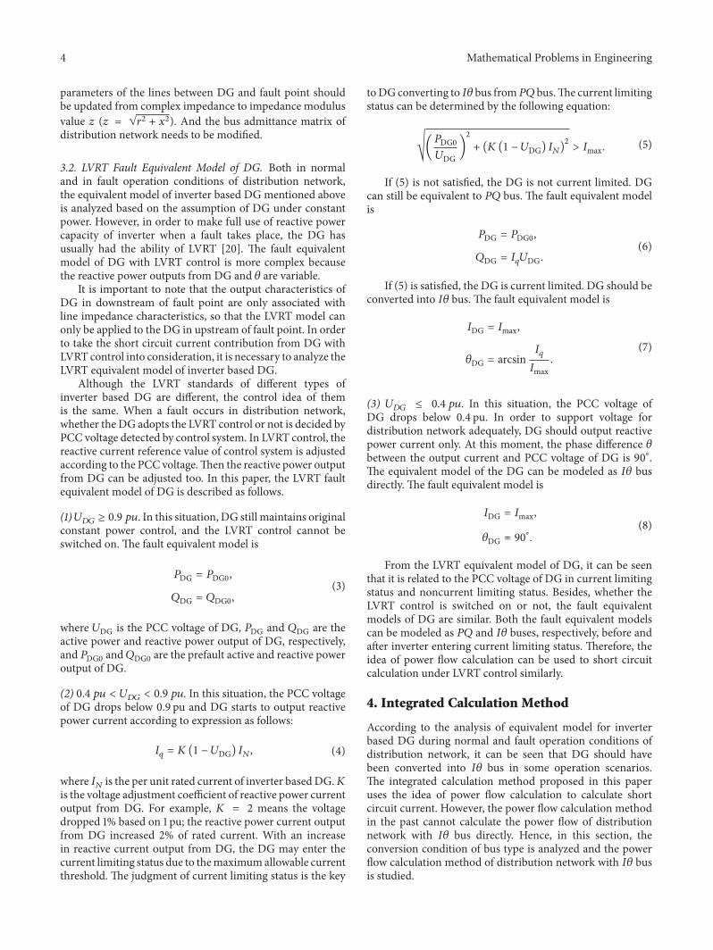
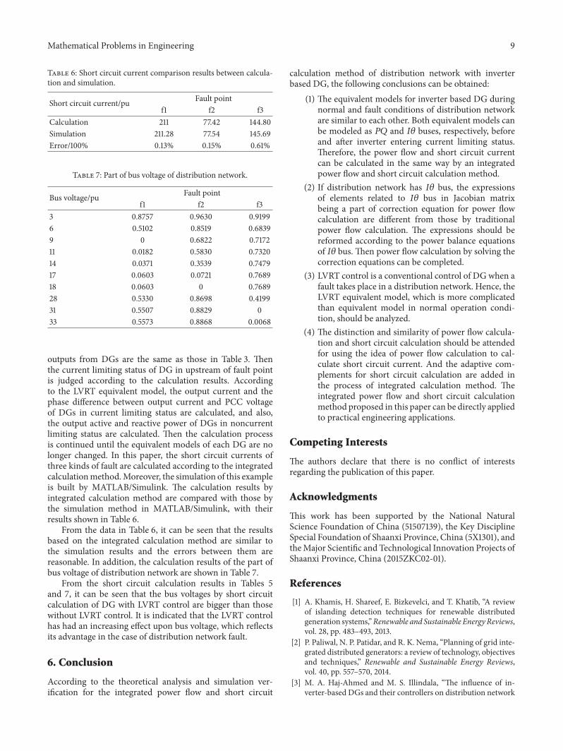


