Embed Size (px)
Citation preview
1087
Sigma J Eng & Nat Sci 37 (4), 2019, 1087-1096
Research Article
DESIGN AND DEVELOPMENT OF A HIGH GAIN DISCONE ANTENNA FOR
4G LTE APPLICATIONS
Aysu BELEN*1, Sezgin ÖRDEK
1,2, Hakan P. PARTAL
1,3
1Yildiz Technical University, Electronics and Communication Engineering, İSTANBUL;
ORCID: 0000-0002-0949-3687 2CTech Bilişim Teknolojileri San. ve Tic. AŞ. T ISTANBUL, ORCID: 0000-0001-9251-7741 3RadarComm, Ltd, YTU Technopark ISTANBUL; ORCID: 0000-0001-8324-8375
Received: 12.04.2019 Revised: 27.08.2019 Accepted: 25.09.2019
ABSTRACT
This study offers the design and realization procedure of a broadband monopole antenna for use in communication applications between 670 MHz-2750 MHz. the proposed monopole antenna comprises a low-
cost discone antenna which has a relatively high gain value over a wide operation band. Firstly, the
performance of the antenna is studied by changing the value of design parameters. Effect of each design parameter on return loss (S11) and gain characteristic of the antenna design is observed and the optimal design
parameters are taken. Both simulation and measurement results of the proposed antenna design show a
matched bandwidth and a return loss of less than -10 dB in the desired operation band of 670 MHz and 2750 MHz. as it can be seen from both simulation and experimental results, the proposed discone antenna design is
a suitable solution for broad-band wireless communication applications.
Keywords: Planar monopole antenna, low profile, airborne, EM simulation, VSWR, discone antenna.
1. INTRODUCTION
Newer communication applications, for optimum use, require single wideband antennas that
can cover a range of frequencies. Recently many techniques had been presented for the design of
high performance antenna for communication systems such as usage of Substrate Integrated
Waveguide structures in antenna designs [1-5], application of Frequency Selective Surfaces for
performance enhancement of antenna designs [6-9], usage of defected Ground Structures [10].
One of the latest antennas to fulfil this need is the planar monopole antenna [11]. This kind of
antenna is adaptable and possesses remarkable features that make it suitable for use in
communication applications. The main features that these applications require from the antenna
that can be employed for wideband applications include radiation pattern stability and impedance
bandwidth with low VSWR. Linear phase response and optimum radiation efficiency are two
other important factors. Application of planar monopole antennas result in a linear phase response
(constant group delay) on a wide band since they have a constant phase center on a wide band of
frequencies [12]. Their designs can be modified for optimum use to cover unusually wide
* Corresponding Author: e-mail: [email protected], tel: (212) 383 58 81
Sigma Journal of Engineering and Natural Sciences
Sigma Mühendislik ve Fen Bilimleri Dergisi

1088
impedance band width with maximum radiation efficiency and a steady omnidirectional radiation
pattern.
These antennas boast of other appealing characteristics such as their conveniently small size
and weight. They are relatively inexpensive to produce and have a simple planar acceptable
structure in accordance with prevailing standards.
Ultra-wide-band (UWB) technology has a great demand in communications in both, civil as
well as military, applications. This is due to the inherent advantages this wide-band technology
possesses such as high-speed data transmission, low interference, relatively low cost, and low
power density [12]. The commonly used wide-band antennas are discone, log-periodic, double-
ridge waveguide horn, and biconical antennas [13-16]. Discone antenna is more popular than the
other antennas mentioned here. This is because of its superior wide-band performance and
omnidirectional radiation that is suitable for UWB systems. Discone antenna has been in use since
1945 when its optimal performance in wide frequency bands was noticed. Its simple design and
structure combined with a low production cost and superior performance encouraged its use in
various communication systems such as wide-band scan antennas, EMC applications, and UWB
systems.
A suggestion for a double discone antenna with tapering wires that can function at a
frequency of 180 MHz to 18 GHz and a VSWR under the value of 2.5 has been made [17]. It
resulted in an omnidirectional radiation pattern that was mostly satisfactory except when it
reached around 12 GHz. Another double discone antenna was developed for a UWB frequency
scan and resulted in a 30:1 broad bandwidth with a VSWR under the value of 2.5 [18].
The forerunner of the discone antenna is the biconical antenna. One of the cones in the
biconical antenna is substituted by a disc, hence the name. The wide-band characteristics of
discone antennas remain the same as those of biconical antennas. These antennas were widely
applied in the fields of radio and television broadcasting as well as avionic systems due to their
unique radiation features. More modifications were made to these antennas in order to make them
more suitable for UWB applications.
One of these modified antennas can be seen in [19] where it operates with an almost
omnidirectional feature in a wide range from 180 MHz to 18 GHz. Another compact modified
version is presented in [20] where it functions optimally in a frequency band between 400 MHz
and 16 GHz. These antennas are created minimally so the bare structure is far cheaper and lighter
than the normally used design.
The disc and the cone are regarded as two monopoles. This results in a considerably lower
characteristic impedance of the antenna when compared to a normal dipole one. In combination
with an appropriate design and frequency, the input impedance of the two monopoles gives
different results.
Herein, design of a high performance broadband monopole antenna consist of a low-cost
discone antenna had been studied. The proposed antenna designed had been aimed to operate at
670-2750 MHz for wireless communication applications. The parametric analysis of the antennas
design parameters over the performance criteria such as S11 and gain had been studied to obtain
the optimal design parameters. Then, for justification of the simulation results the antenna design
had been prototyped and measured. In the next section the design, simulation and prototyping of
the discone antenna are presented. After that, the measurement results of the discone are
investigated, finally paper ends with conclusion section.
2. DESIGN PROCEDURE of DISCONE ANTENNA
This study makes some important modifications by introducing a short circuit loading method
and alters the surface profile into a broken line. Traditionally, the discone antenna direction figure
bandwidth is extremely narrow and the diameter of the disc should be raised in order to get a
good directional diagram characteristic. But the drawback of this method is that the low frequency
A. Belen, S. Ördek, H.P. Partal / Sigma J Eng & Nat Sci 37 (4), 1087-1096, 2019
1089
standing wave is reduced. In order to acquire index requirements, the size of the antenna must be
increased. However, this puts constraints on the applications it can be used for. Hence it
necessitates the changes mentioned earlier so the incongruity between the antenna technology
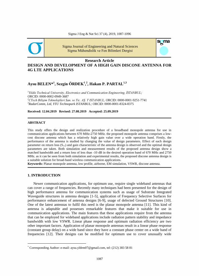
index and the dimensional needs can be resolved optimally. The dimensions of the proposed
discone antenna (Figs. 1-2) are given in table I, alongside of the simulated gain and VSWR results
in Figs 3-4 and table II.
2R
D
S
HФh
DC
DC1
Figure 1. Dimensional views of design and its 3D model views of design HFSS
Figure 2. Three-Dimensional Simulation Model
Table 1. Design Parameters of the Proposed Antenna
D 95 S 2
R 1.4 DC 120
H 130 DC1 6.30
Фh 300
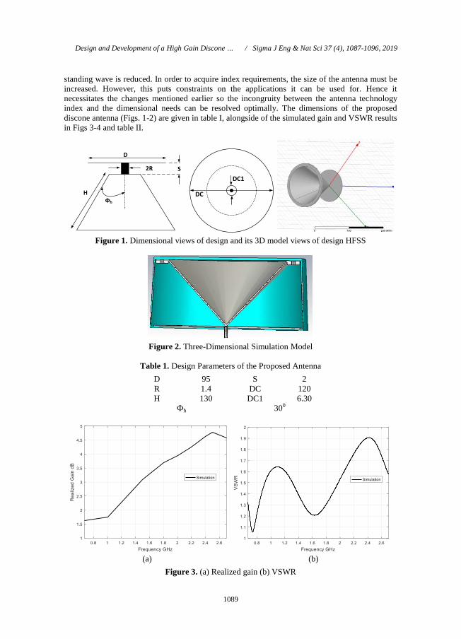
(a) (b)
Figure 3. (a) Realized gain (b) VSWR
Design and Development of a High Gain Discone … / Sigma J Eng & Nat Sci 37 (4), 1087-1096, 2019

1090
(a) (b)
(c) (d)
(e) (f)
Figure 4. Realized Gain 3D at (a)670MHz (b)900MHz (c)1500MHz (d)1800MHz (e)2400MHz
(f)2750MHz
A. Belen, S. Ördek, H.P. Partal / Sigma J Eng & Nat Sci 37 (4), 1087-1096, 2019
1091
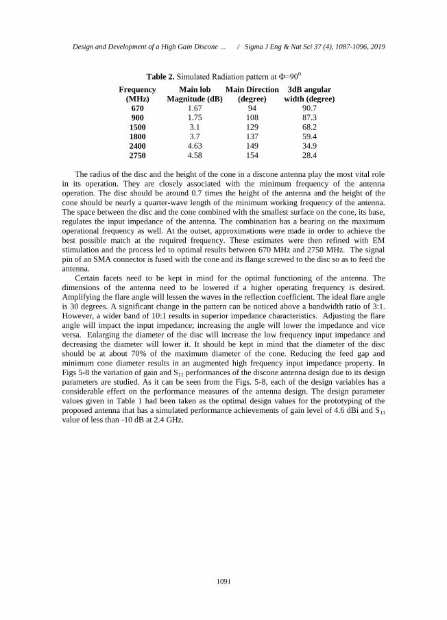
Table 2. Simulated Radiation pattern at Ф=900
Frequency
(MHz)
Main lob
Magnitude (dB)
Main Direction
(degree)
3dB angular
width (degree)
670 1.67 94 90.7
900 1.75 108 87.3
1500 3.1 129 68.2
1800 3.7 137 59.4
2400 4.63 149 34.9
2750 4.58 154 28.4
The radius of the disc and the height of the cone in a discone antenna play the most vital role
in its operation. They are closely associated with the minimum frequency of the antenna
operation. The disc should be around 0.7 times the height of the antenna and the height of the
cone should be nearly a quarter-wave length of the minimum working frequency of the antenna.
The space between the disc and the cone combined with the smallest surface on the cone, its base,
regulates the input impedance of the antenna. The combination has a bearing on the maximum
operational frequency as well. At the outset, approximations were made in order to achieve the
best possible match at the required frequency. These estimates were then refined with EM
stimulation and the process led to optimal results between 670 MHz and 2750 MHz. The signal
pin of an SMA connector is fused with the cone and its flange screwed to the disc so as to feed the
antenna.
Certain facets need to be kept in mind for the optimal functioning of the antenna. The
dimensions of the antenna need to be lowered if a higher operating frequency is desired.
Amplifying the flare angle will lessen the waves in the reflection coefficient. The ideal flare angle
is 30 degrees. A significant change in the pattern can be noticed above a bandwidth ratio of 3:1.
However, a wider band of 10:1 results in superior impedance characteristics. Adjusting the flare
angle will impact the input impedance; increasing the angle will lower the impedance and vice
versa. Enlarging the diameter of the disc will increase the low frequency input impedance and
decreasing the diameter will lower it. It should be kept in mind that the diameter of the disc
should be at about 70% of the maximum diameter of the cone. Reducing the feed gap and
minimum cone diameter results in an augmented high frequency input impedance property. In
Figs 5-8 the variation of gain and S11 performances of the discone antenna design due to its design
parameters are studied. As it can be seen from the Figs. 5-8, each of the design variables has a
considerable effect on the performance measures of the antenna design. The design parameter
values given in Table 1 had been taken as the optimal design values for the prototyping of the
proposed antenna that has a simulated performance achievements of gain level of 4.6 dBi and S11
value of less than -10 dB at 2.4 GHz.
Design and Development of a High Gain Discone … / Sigma J Eng & Nat Sci 37 (4), 1087-1096, 2019

1092
(a) (b)
Figure 5. (a) Reflection Coefficient (b) Realized Gain simulated result (parameter sweep, discone
gap between 1mm to 3mm, step width: 1mm)
(a) (b)
Figure 6. Reflection (a) Reflection Coefficient (b)Realized Gain simulated result (parameter
sweep, discone diameter maximum between 100mm to 140mm, step width:10mm)
(a) (b)
Figure 7. (a) Reflection Coefficient (b) Realized Gain simulated result (parameter sweep, disc
diameter maximum between 75mm to 115mm, step width: 10mm)
A. Belen, S. Ördek, H.P. Partal / Sigma J Eng & Nat Sci 37 (4), 1087-1096, 2019
1093
(a) (b)
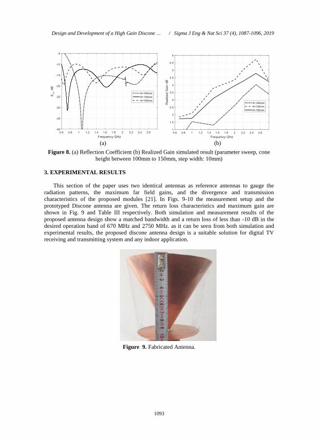
Figure 8. (a) Reflection Coefficient (b) Realized Gain simulated result (parameter sweep, cone
height between 100mm to 150mm, step width: 10mm)
3. EXPERIMENTAL RESULTS
This section of the paper uses two identical antennas as reference antennas to gauge the
radiation patterns, the maximum far field gains, and the divergence and transmission
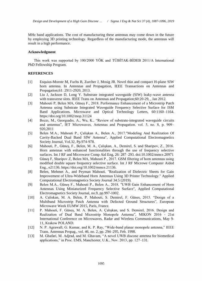
characteristics of the proposed modules [21]. In Figs. 9-10 the measurement setup and the
prototyped Discone antenna are given. The return loss characteristics and maximum gain are
shown in Fig. 9 and Table III respectively. Both simulation and measurement results of the
proposed antenna design show a matched bandwidth and a return loss of less than -10 dB in the
desired operation band of 670 MHz and 2750 MHz. as it can be seen from both simulation and
experimental results, the proposed discone antenna design is a suitable solution for digital TV
receiving and transmitting system and any indoor application.
Figure 9. Fabricated Antenna.
Design and Development of a High Gain Discone … / Sigma J Eng & Nat Sci 37 (4), 1087-1096, 2019

1094
(a) (b)
Figure 10. (a) Measurement setup for maximum far field gain [9] (b) Measurement and
Simulation Comparison for Return loss
Table 3. Comparison between Discone Simulation and Measurement
Gain
(dBi)
Frequency
(MHz) Simulated Measured
670 1.6 ---*
900 1.7 1.1
1500 3.2 3.8
1800 3.7 3.1
2400 4.6 3.9
2750 4.2 4.4
*can not be measured due to the limitation of reference antenna
Table 4. Comparison Literature
Size (mm) Operation
Frequency GHz
S11 dB VSWR Max Gain dBi
[22] 368x368x377 0.12-18 --- <2.5 8
[23] 26x26x20 3.1-4.1 <-10 <2 2
[24] 144x144x165 0.38-3 <-10 --- 1.8
[25] 40x40x18.5 2.15-7 <-10 --- 5.3
[26] 55.2x55.2x22 1.7-2.7 <-10 --- 3.6
This Study 120x120x110 0.67-2.75 <-12 --- 4.4
4. CONCLUSION
Herein, a simple and low-cost design and realization of a discone antenna with a high gain
and low-cost for use in 670 MHZ-2750 MHz microwave applications had been proposed. For this
purpose, the operating principles of the antenna were studied by plotting the variation of S11 and
Gain characteristics of the antenna design due to the change in design parameters. After the
parametric analysis of the antenna design the optimal design values are taken to make an
experimental model of the proposed antenna. Then both simulation and experimental results
showed a high gain and good return loss characteristic. Form the measurement results it can be
concluded that the proposed antenna is a suitable model for indoor application use in 670-2750
A. Belen, S. Ördek, H.P. Partal / Sigma J Eng & Nat Sci 37 (4), 1087-1096, 2019
1095
MHz band applications. The cost of manufacturing these antennas may come down in the future
by employing 3D printing technology. Regardless of the manufacturing mode, the antennas will
result in a high performance.
Acknowledgment
This work was supported by 100/2000 YÖK and TÜBİTAK-BİDEB 2011/A International
PhD Fellowship Program.
REFERENCES
[1] Esquius-Morote M, Fuchs B, Zurcher J, Mosig JR. Novel thin and compact H-plane SIW
horn antenna. In Antennas and Propagation, IEEE Transactions on Antennas and
Propagation;61: 2911-2920, 2013.
[2] Liu J, Jackson D, Long Y. Substrate integrated waveguide (SIW) leaky-wave antenna
with transverse slots. IEEE Trans on Antennas and Propagation;60:20-29, , Jan 2012.
[3] Mahouti P, Belen MA, Güneş F., 2018. Performance Enhancement of a Microstrip Patch
Antenna using Substrate Integrated Waveguide Frequency Selective Surface for ISM
Band Applications. Microwave and Optical Technology Letters, 60:1160–1164.
https://doi.org/10.1002/mop.31124
[4] Bozzı, M., Georgıadıs, A., Wu, K., “Review of substrate-integrated waveguide circuits
and antennas”, IET Microwaves, Antennas and Propagation. vol. 5, no. 8, p. 909–
920,2011
[5] Belen M.A., Mahouti P., Çalişkan A., Belen A., 2017."Modeling And Realization Of
Cavity-Backed Dual Band SIW Antenna", Applied Computational Electromagnetics
Society Journal, Vol.32, Pp.974-978.
[6] Mahouti, P., Güneş, F., Belen, M. A., Çalışkan, A., Demirel, S. and Sharipov, Z., 2016.
Horn antennas with enhanced functionalities through the use of frequency selective
surfaces. Int J RF and Microwave Comp Aid Eng, 26: 287–293. doi:10.1002/mmce.20971
[7] Güneş F, Sharipov Z, Belen MA, Mahouti P., 2017. GSM filtering of horn antennas using
modified double square frequency selective surface. Int J RF Microwe Computer Aided
Eng., e21136. https://doi.org/10.1002/mmce.21136.
[8] Belen, Mehmet A., and Peyman Mahouti. "Realization of Dielectric Sheets for Gain
Improvement of Ultra-Wideband Horn Antennas Using 3D Printer Technology." Applied
Computational Electromagnetics Society Journal 34.5 (2019).
[9] Belen M.A., Güneş F., Mahouti P., Belen A., 2018. "UWB Gain Enhancement of Horn
Antennas Using Miniaturized Frequency Selective Surface", Applied Computational
Electromagnetics Society Journal, no.9, pp.997-1002.
[10] A. Caliskan, M. A. Belen, P. Mahouti, S. Demirel, F. Günes, 2015. “Design of a
Multiband Microstrip Patch Antenna with Defected Ground Structures”, European
Microwave Week EUMW 2015, Paris, France.
[11] P. Mahouti, F. Güneş, M. A. Belen, A. Çalışkan, and S. Demirel, 2016. Design and
Realization of Dual Band Microstrip Monopole Antenna”, MIKON 2016 - 21st
International Conference on Microwaves, Radar and Wireless Communications, May 9-
11, Krakow POLAND.
[12] N. P. Agrawall, G. Kumar, and K. P. Ray, “Wide-band planar monopole antenna,” IEEE
Trans. Antennas Propag., vol. 46, no. 2, pp. 294–295, Feb. 1998.
[13] M. Ghafari, M. Adjrad, and M. Ghavam, “A novel UWB discone antenna for biomedical
applications,” in Proc. EMS, Manchester, U.K., Nov. 2013, pp. 127–131.
Design and Development of a High Gain Discone … / Sigma J Eng & Nat Sci 37 (4), 1087-1096, 2019
1096
[14] K. Nagasawa and I. Matsuzuka, “Radiation field consideration of biconical horn antenna
with different flare angles,” IEEE Trans. Antennas Propag., vol. 36, no. 9, pp. 1306–1310,
Sep. 1988.
[15] Y. Jian, “On conditions for constant radiation characteristics for logperiodic array
antennas,” IEEE Trans. Antennas Propag, vol. 58, no. 5, pp. 1521–1526, May 2010.
[16] B. Jacobs, J. W. Odendaal, and J. Joubert, “An improved design for a 1–18 GHz double-
ridged guide horn antenna,” IEEE Trans. Antennas Propag., vol. 60, no. 9, pp. 4110–
4118, Sep. 2012.
[17] K. H. Kim, J. U. Kim, and S. O. Park, “An ultrawide-band double discone antennawith
the tapered cylindrical wires,” IEEE Trans. Antennas Propag., vol. 53, no. 10, pp. 3403–
3406, Oct. 2005.
[18] J. U. Kim and S. O. Park, “Novel ultra-wideband discone antenna,” Microw. Opt.
Technol. Lett., vol. 42, pp. 113–115, Jul. 2004.
[19] K.-H. Kim, J.-U. Kim, and S.-O. Park, “An ultrawide-band double discone antenna with
the tapered cylindrical wires,” Antennas and Propagation, IEEE Transactions on, vol. 53,
no. 10, pp. 3403–3406, Oct 2005.
[20] Y. Zhao and W. Wang, “Design of a novel broadband skeletal discone antenna with a
compact configuration,” Antennas and Wireless Propagation Letters, IEEE, vol. PP, no.
99, pp. 1–1, 2014.
[21] A-info, LB8180, 0.8-18 GHz Broadband Horn Antenna, Available
at: http://www.ainfoinc.com/en/p_ant_h_brd.asp, Accessed on November 9, 2015.
[22] Irfan Shahid,1 Fawad Hussain,1 Jehanzeb Burki,2 and M. Shoaib Arif, “An
Ultrawideband Inverted Double Discone Antenna With 150:1 Impedance Bandwidth”,
Microwave And Optical Technology Letters / Vol. 58, No. 1, January 2016 DOI
10.1002/mop
[23] Mehran Ghafari, Mounir Adjrad, Mohammad Ghavami, “A Novel UWB Discone
Antenna for Biomedical Applications ”, 2013 European Modelling Symposium
[24] Ricardo Gonc¸alves1, Pedro Pinho1;2 and Nuno B. Carvalho, “Design and
implementation of a 3D printed discone antenna for TV broadcasting system”, 2015 IEEE
International Symposium on Antennas and Propagation & USNC/URSI National Radio
Science Meeting, DOI: 10.1109/APS.2015.7304543
[25] D. Tran, M. Wang and A. Yarovoy, “Ultra Wideband Slot-loaded, Dielectric-filled
Discone Antenna for WLAN Applications”, 2016 10th European Conference on
Antennas and Propagation (EuCAP), DOI: 10.1109/EuCAP.2016.7481352
[26] Yiqiang Yu, Hongmei Zhang, Zhizhang Chen, “A Broadband Dual-Polarized
Omnidirectional MIMO Antenna for 4G LTE Applications”, Progress In
Electromagnetics Research Letters, Vol. 57, 91–96, 2015.
A. Belen, S. Ördek, H.P. Partal / Sigma J Eng & Nat Sci 37 (4), 1087-1096, 2019