Embed Size (px)
Citation preview

Hindawi Publishing CorporationInternational Journal of Antennas and PropagationVolume 2013 Article ID 747629 12 pageshttpdxdoiorg1011552013747629
Research ArticleA Small Ku-Band Polarization Tracking Active Phased Array forMobile Satellite Communications
Wei Shi12 Zuping Qian1 Jun Zhou34 Xinbo Qu2 Yang Xiang2 and Liu Hong2
1 Institute of Communication Engineering PLA University of Science and Technology Nanjing 210016 China2 Antenna Research Laboratory Nanjing Telecommunication Technology Institute Nanjing 210007 China3 State Key Laboratory of Millimeter Waves Southeast University Nanjing 210096 China4Department of Micro-systems Nanjing Electronic Device Institute Nanjing 210096 China
Correspondence should be addressed to Wei Shi sw antsinacom
Received 19 April 2013 Revised 21 September 2013 Accepted 22 September 2013
Academic Editor Z N Chen
Copyright copy 2013 Wei Shi et al This is an open access article distributed under the Creative Commons Attribution License whichpermits unrestricted use distribution and reproduction in any medium provided the original work is properly cited
A compact polarization tracking active phased array for Ku-band mobile satellite signal reception is presented In contrastwith conventional mechanically tracking antennas the approach presented here meets the requirements of beam tracking andpolarization tracking simultaneously without any servo components The two-layer stacked square patch fed by two probes is usedas antenna element The impedance bandwidth of 16 for the element covers the operating frequency range from 1225GHz to1275GHz In the presence of mutual coupling the dimensional parameters for each element of the small 7times 7 array are optimizedduring beam scanning and polarization trackingThe compact polarization trackingmodules based on the low-temperature cofiredceramic (LTCC) system-in-package (SiP) technology are proposed A small active phased array prototype with the size of 120mm(length)times 120mm (width)times 55mm (height) is developed The measured polarization tracking patterns of the prototype are givenThe polarization tracking beam can be steered in the elevation up to 50∘The gain of no less than 160 dBi and the aperture efficiencyof more than 50 are obtained The measured and simulated polarization tracking patterns agreed well
1 Introduction
Geostationary satellite communication is widely used inmilitary and civilian fields for wide area coverage In orderto improve communication capacity Ku-band satellite com-munication system utilizes orthogonal linear polarizationtransmission in both uplink (140GHzsim145 GHz) and down-link (1225GHzsim1275GHz) for frequency reuse The mobileantenna terminals may not point to the satellite when thereis the rapid change in azimuth pitch and roll of vehiclesairplanes and ships One challenge for mobile antennaterminals in Ku-band is to avoid polarization mismatchTherefore the mobile antenna terminals in Ku-band shouldmeet the requirements of beam tracking and polarizationtracking simultaneously
Reflector or lens antenna is used most widely for itshigh efficiency and low cost [1ndash3] The beam pointing andpolarization are steered mechanically But the requirementfor low profile and high tracking speed is not easily met
The mechanically tracking array antenna of stair structurehas lower profile [4 5] but the low radiating efficiency andrelatively higher sidelobe limit its use in some applicationsThe hybrid tracking planar antenna combines mechanicaltracking in azimuth and electronic tracking in elevation [6 7]However it is difficult to integrate the mechanical servocomponents with the top surface of the vehicles airplanesand ships
This paper presents a new polarization tracking activephased array based on LTCC-SiP polarization tracking mod-ule The beam and the orientation of the linear polarizationcan be electronically steered simultaneously [8] The radiat-ing element is based on a stacked square microstrip patchorthogonally fed by two probes Each probe excites hori-zontally or vertically polarized wave Therefore the arbitrarylinear polarization can be obtained through the combinationof two orthogonal polarizations We have designed a newcompact polarization tracking module with the LTCC-SiPtechnology which can be used to reduce the height of
2 International Journal of Antennas and Propagation
Wup
Wup
Top substrate h2 1205762
Foam h3 1205763
Bottom substrate h1 1205761
Wlow
Wlow
Lprobe
Lprobe
w
w
Port Hl
l
Port V
Figure 1 Configuration of the antenna element fed by two orthogonal probes
the arrayThe phase and polarization of the radiating elementcan be electronically controlled by the phase settings of themodule
A model for the small 7 times 7 array was established usingCSTMicrowave StudioWe analyzed the impedance variationof central element during beam scanning and polarizationtracking in the presence of mutual coupling Based onthe simulated results a small polarization tracking activephased array prototype for reception in the frequency rangefrom 1225GHz to 1275GHz was developed The height ofthe array is only 55mm In the microwave chamber themeasured radiation patterns for vertical horizontal anddiagonal polarization were obtained via phase settings ofthe proposed polarization tracking modules The beam canbe electronically steered up to 50∘ in the elevation Thedeveloped prototype has the minimum gain of 160 dBi andthe aperture efficiency of 50 The measured polarizationtracking patterns and the simulated ones agree well whichdemonstrates the usefulness of the design method based onmutual coupling
2 Array Design Based on Mutual Coupling
The arbitrary linearly polarized wave can be decomposedinto vertically and horizontally polarized component withthe same phase and different amplitude Thus the radiatingelement with orthogonal dual ports radiates vertically andhorizontally polarized wave simultaneously The weightedcoefficients for the dual ports of the radiating element can
be controlled via the phase settings of polarization trackingmodule and the linear polarization of arbitrary orientationcan be obtained Thus the antenna array has the capabilityof polarization tracking without mechanical rotation of thewhole array
The cross-dipoles can be used as the radiating elementfor polarization tracking phased array [9] but the height ofthe element is 048 120582
0 The dual aperture coupled microstrip
antenna can also be used to radiate orthogonally polar-ized waves [3 7] However the coaxial connecters of themicrowave modules result in the difficulty of connectionsbetween the aperture-coupled antenna elements and themodules For low profile easy fabrication and low cost two-layer stacked square microstrip antenna with dual probesis used as radiating element as shown in Figure 1 Broadbandwidth can be obtained with electromagnetic couplingmechanism between top and bottom patches Arlon Diclad880 with 120576
119903= 22 and ℎ = 0508mm is used for top and
bottom substrates Rohacell HF51 with 120576119903= 105 and ℎ =
15mm is used for the foam With the symmetrical structureof the square patch portH and port V approximately have thesame radiation pattern and resonance frequency Thereforethe little effect of the patterns on the polarization combinationcan be neglected and the amplitude and phase weightedcoefficients of dual ports determine the final polarization ofthe radiating element
The square grid arrangement for the radiating elementsis used for the simplicity of the feed network We designed asmall 7 times 7 array shown in Figure 2 which may be equivalent
International Journal of Antennas and Propagation 3
R1 R2-2 R3-3 R4-4 R5-5
R2-1 R3-2 R4-3 R5-4 R4-4
R3-1 R4-2 R5-3 R4-3 R3-3
R4-1 R5-2 R4-2 R3-2 R2-2
R5-1 R4-1 R3-1 R2-1 R1
(a) Layout
y
xo
120593
(b) Coordinate system
Figure 2 Topology of the small array (the outermost elements with gray color indicate passive elements terminated with 50Ω matchedloads)
0
minus5
minus10
minus15
minus20
minus25
S11S12
|S11|
(dB)
0
minus5
minus10
minus15
minus20
minus30
minus25
minus35
|S12|
(dB)
100 110 120 130 140 150Frequency (dB)
Figure 3 The simulated 11987811
and 11987812
of isolated antenna element
to a large array for the center element R5-3 Thus the effectof mutual coupling on the impedance of radiating element aswell as active element pattern can be analyzedThe radiatingelements are spaced a distance of 05 120582
0 wherein 120582
0is the
wavelength in free space at 125 GHzThe outermost elementswith gray color are terminated with loads of 50Ω to formpassive elements which are used to solve the problem ofdeterioration of edge element pattern of the inner 5times5 activearray
We used software CST Microwave Studio to design theisolated radiating element Array A in Table 1 was formed by7 rows of 7 elements designed without considering mutualcoupling The structural symmetry of isolated element con-tributes to the same simulated reflection coefficients of dualports shown in Figure 3 The simulated 10 dB impedancebandwidth (|119878
11| lt minus10 dB) was found to be 16 (18 GHzsim
138 GHz) which is sufficient for Ku-band satellite receiversystem Furthermore the coupling coefficient between port
Table 1 The structural parameters for the radiating element (unitmm)
Element parameters 119882up 119882low 119908 119897 119871probe
Array A (initial design ) 75 78 14 105 04Array B (final design ) 66 79 085 105 04
H and port V is belowminus18 dBHowever the difficult challengewith the polarization tracking phased array is the mutualcoupling which will result in the variation of the portimpedance of each element during polarization tracking andbeam scanningThus the design parameters in Table 1 for theradiating element in array A may be not optimum due tothe presence of mutual coupling thereby degrading the arrayperformance
A small array model was established in CST MicrowaveStudio for mutual coupling analysis If the amplitude
4 International Journal of Antennas and Propagation
Port V
Port H
0 5 10 15 20 25 30 35 40 45 50Scan angle (deg)
minus5
minus10
minus15
minus20
minus25
minus30
Activ
e refl
ectio
n co
effici
ent (
dB)
1225 GHz125 GHz1275GHz
(a) Array A
Port V
Port H
0 5 10 15 20 25 30 35 40 45 50Scan angle (deg)
minus10
minus16
minus20
minus28
minus34
minus32
minus30
minus26
minus24
minus22
minus18
minus14
minus12
Activ
e refl
ectio
n co
effici
ent (
dB)
1225 GHz125 GHz1275GHz
(b) Array B
Figure 4 The active reflection coefficient of central element R5-3 (azimuth angle 120593 = 0∘ vertical polarization)
Port V
Port H
0 5 10 15 20 25 30 35 40 45 50Scan angle (deg)
minus5
minus10
minus15
minus20
minus25
minus30
Activ
e refl
ectio
n co
effici
ent (
dB)
1225 GHz125 GHz1275GHz
(a) Array A
Port V
Port H
0 5 10 15 20 25 30 35 40 45 50Scan angle (deg)
minus5
minus10
minus15
minus20
minus25
minus30
Activ
e refl
ectio
n co
effici
ent (
dB)
1225 GHz125 GHz1275GHz
(b) Array B
Figure 5 The active reflection coefficient of central element R5-3 (azimuth angle 120593 = 0∘ horizontal polarization)
weighted coefficients for the orthogonal ports (port Hand port V) are (1 0) (0 1) and (1 1) respectivelythe small array will radiate vertically horizontally anddiagonally polarized wave In each polarization the beamcan be steered from 0∘ to 50∘ in elevation with phase vari-ation between antenna elements The key dimensionalparameters 119882up 119882low and 119908 can be adjusted via simulationtomitigate themutual coupling effect on the variation of portimpedance during polarization tracking and beam scanningThe new parameters of radiating elements proposed for arrayB are given in Table 1 The variations of active reflection
coefficient of central element R5-3 in both array A and arrayB are given in Figures 4 5 and 6 Compared with array A theactive reflection coefficient of central element R5-3 in arrayB has been reduced generally when the polarization trackingbeam is steered in the119909119911-plane (120593 = 0∘) within the scan rangeofplusmn25∘ As the scan angle increases the performance of activereflection coefficient of array B degrades gradually whichis obvious especially for the diagonal polarization Whenthe beam is steered to 50∘ in elevation the active reflectioncoefficient of about minus7 dB in the frequency range can beachieved for port HThe gain versus scan angle of both array
International Journal of Antennas and Propagation 5
minus5
minus6
minus7
minus8
minus9
minus10
minus11
minus12
minus13
minus14
minus15
minus16
minus17
minus18
Activ
e refl
ectio
n co
effici
ent (
dB)
0 5 10 15 20 25 30 35 40 45 50Scan angle (deg)
1225 GHz125 GHz1275GHz
Port V
Port H
(a) Array A
minus6
minus8
minus10
minus12
minus14
minus16
minus18
Activ
e refl
ectio
n co
effici
ent (
dB)
0 5 10 15 20 25 30 35 40 45 50Scan angle (deg)
1225 GHz125 GHz1275GHz
Port V
Port H
(b) Array B
Figure 6 The active reflection coefficient of central element R5-3 (azimuth angle 120593 = 0∘ diagonal polarization)
A and array B was computed for comparison The simulatedresults for three typical polarizations are shown in Figure 7The gain improvement for array B can be observed
As shown in Figure 8 a small 7 times 7 element array wasfabricated based on the dimensional parameters of array BThe active element patterns of central element R5-3 weremeasured when all of the other ports except for port V wereterminated with passive loads of 50Ω With reference toFigure 2 the 119909119911-plane (120593 = 0∘) is the H-plane for port V andthe 119910119911-plane (120593 = 90∘) is the E-planeThe active element pat-terns of central element R5-3 in H- and E-planes are given inFigure 9 In the area of the main lobe the agreement betweenthe simulated and measured results can be observed Boththe simulated and measured results indicate the half-powerbeamwidth of approximately 120∘ and 112∘ in the H-planeand the E-plane respectively No blind spot is observed Dueto the approximate symmetry in structure the active elementpattern of port H has the similarity with that of port V
3 Polarization Tracking Module
The polarization tracking modules are key components forthe polarization tracking active phased array The dualinput ports shown in Figure 10(b) are connected to theorthogonal dual ports of antenna element The dual inputsfrom port V and port H can be combined into singleoutput in phase via differential phase setting Δ120593 Thus thepolarization mismatch with incoming wave from satellitecan be avoided Figure 10(a) shows the coordinate sys-tem based on the unit vectors of orthogonal polarizationswherein 997888V and
997888
ℎ denote the vertical and horizontal polar-izations respectively The orientation of polarization for theincoming wave is denoted by 997888119901 and the included angleformed by 997888119901 and 997888V is denoted by 997888120572 If we neglect the
effects of radiation patterns of dual ports the inputs of theLange coupler are obtained as follows
PortC
1199063= 119886radic119866amp cos120572 (1a)
PortD
1199064= 119886radic119866amp sin120572 (1b)
wherein 119866amp is the gain of the LNA Assuming that the twochannels are consistent the signal at the output of the receivermodule can be yielded as
119906119888=
119886
2radic119871119879
radic119866amp exp [119895 (180∘
minus 120572 + 1205930)]
+
119886
2radic119871119879
radic119866amp exp [119895 (90∘
+ 1205930+ Δ120593 + 120572)]
(2)
Herein 119871119879is the average insertion loss in each channel
If the phase factor in (2) satisfies the condition as follows
Δ120593 = 90∘
minus 2120572 (3)
the combined signal has no polarization mismatch loss Inthis case the maximum combined signal is given as
119906119888=
119886
radic119871119879
radic119866amp exp [119895 (180∘
minus 120572 + 1205930)] (4)
Based on LTCC technology a vertical transition fromcoplanar waveguide to stripline is presented to reduce thesize of the module [10] Figure 11 shows the vertical transitionconfiguration and fabricated prototype The simulated and
6 International Journal of Antennas and Propagation
190
185
180
175
170
165
Gai
n (d
Bi)
minus10 0 10 20 30 40 50 60Scan angle (deg)
Array B (final design)Array A (initial design)
(a) Horizontal polarization
190
185
180
175
170
Gai
n (d
Bi)
minus10 0 10 20 30 40 50 60Scan angle (deg)
Array B (final design)Array A (initial design)
(b) Vertical polarization
190
185
180
175
170
Gai
n (d
Bi)
minus10 0 10 20 30 40 50 60Scan angle (deg)
Array B (final design)Array A (initial design)
(c) Diagonal polarization
Figure 7 The comparison of gain during polarization tracking and beam scanning (azimuth angle 120593 = 0∘)
Figure 8 Front view of the fabricated array
International Journal of Antennas and Propagation 7
50
minus5
minus10
minus15
minus20
minus25
minus30
minus35
minus40
minus45
minus50
minus55
minus60
Relat
ive a
mpl
itude
(dB)
MeasuredSimulated
minus180 minus120 minus60 0 60 120 180Angle (deg)
(a) 120593 = 0∘ (H-plane)
50
minus5
minus10
minus15
minus20
minus25
minus30
minus35
minus40
minus45
minus50
Relat
ive a
mpl
itude
(dB)
MeasuredSimulated
minus180 minus120 minus60 0 60 120 180Angle (deg)
(b) 120593 = 90∘ (E-plane)
Figure 9 The active element pattern of central element R5-3 fed from port V
120572
p
h
(a) Polarization decomposition
Receiving element
Port VPort H
LNA 2LNA 1
Lange coupler
1205930 1205930 + Δ120593
Power combiner
1 2
3 4
(b) Schematic block diagram
Figure 10 The polarization tracking module for receiving application
Ground
Coplanar waveguide
Metalized via LTCC
OutputInput
Motherboard
Stripline
(a) Schematic diagram (b) Prototype
Figure 11 Transition from planar waveguide to stripline based on LTCC technology
8 International Journal of Antennas and Propagation
0
minus15
minus30
minus45
minus60
|S11|
(dB)
0 2 4 6 8 10 12 14 16 18Frequency (GHz)
00
minus25
minus50
minus75
minus100
Inse
rtio
n lo
ss (d
B)
MeasuredSimulated
Figure 12 Reflection coefficient and insertion loss of the LTCC-based vertical transition
(a) Top view (b) Bottom view
Figure 13 The fabricated compact polarization tracking module
measured reflection coefficient and insertion loss are plottedin Figure 12 It is observed that good agreement can beobtained between the simulated and measured results from2GHz to 18GHzThemeasured reflection coefficient is belowminus16 dB and the insertion loss is less than 15 dB We usedthe compact structure of the vertical transition to developa polarization tracking module integrated with multipleMMICs which is shown in Figure 13 With reference toFigure 10(b) the gain of two channels of the module wasmeasured with 120593
0= 0∘ when Δ120593 was increased from 0∘ to
minus360∘ with a step of minus5625∘ With reference to Figure 14the measured gain of both channels varies in the range fromabout 10 dB to 35 dBwith different trend which is determinedby the differential phase Δ120593 between two channels Thusthe different amplitude weighted coefficients for both port Vand port H can be achieved which results in the arbitrarylinear polarization of the antenna element With referenceto Figure 14 the diagonal polarization (120572 = 45∘ and 120572 =minus45∘) can be obtained due to the approximately same gain
of both channels with Δ120593 = 0∘ and minus180∘ The approximatevertical polarization can be obtained with Δ120593 = minus90∘ whenthe measured gains of port H and port V are about 105 dBand 337 dB The approximate horizontal polarization can beobtained with Δ120593 = minus270∘ when the measured gains of portH and port V are about 342 dB and 105 dB
4 Experiment Result
A small 7 times 7 polarization tracking active phased arraywas fabricated to cover the frequency range from 1225GHzto 1275GHz The inner 5 times 5 radiating elements are con-nected to the polarization tracking modules discussed aboveThe miniature 50Ω SMP female terminations are used asmatched loads directly connecting to the outermost 24passive radiating elements The schematic block diagram ofthe fabricated array is shown in Figure 15 The compact-ness of the polarization tracking module based on LTCC-SiP technology contributes to the low-profile phased arraywith the size of 120mm (length)times 120mm (width) times 55mm(height) The polarization tracking patterns were measuredin 119909119911-planeThe antenna prototype to be measured was fixedon the rotary platform in the microwave chamber and thepolarization can be controlled electronically without rotatingthe array aperture The patterns for horizontal vertical anddiagonal polarization can be measured respectively withΔ120593 = minus270
∘
minus90∘ and 0∘ The narrow bandwidth of
4 determines the stable radiation patterns over the entireoperating frequency range from 1225GHz to 1275GHzThus the polarization tracking patternsmeasured at 125GHzwith beam scanned to 0∘ 20∘ 40∘ and 50∘ are given inFigures 16 17 18 and 19 The reasonable agreement between
International Journal of Antennas and Propagation 9
40
35
30
25
20
15
10
5
Differential phase (deg)
Gai
n (d
B)
Port HPort V
0 minus45 minus90 minus135 minus180 minus225 minus270 minus315 minus360
Figure 14 The measured transmission gain versus the differential phase Δ120593 for port H and port V
Polarizationtrackingmodule
Polarizationtrackingmodule
Polarizationtrackingmodule
Polarizationtrackingmodule
Polarizationtrackingmodule
Power combiner network
Beam and polarizationcontroller
Antenna array
middot middot middot
middot middot middot
middot middot middot
Figure 15 The schematic block diagram of the fabricated polarization tracking active phased array
minus90
minus80
minus70
minus60
minus50minus40
minus30minus20minus10
0 10 2030
4050
6070
8090
0minus5
minus10
minus15
minus20
minus25
minus30
minus35Relat
ive a
mpl
itude
(dB) 20 20
(a) Horizontal polarization
minus90
minus80
minus70
minus60
minus50minus40
minus30minus20minus10
0 10 2030
4050
6070
8090
0minus5
minus10
minus15
minus20
minus25
minus30
minus35Relat
ive a
mpl
itude
(dB) 20 20
(b) Vertical polarization
minus90
minus80
minus70
minus60
minus50minus40
minus30minus20minus10
0 10 2030
4050
6070
8090
MeasuredSimulated
0minus5
minus10
minus15
minus20
minus25
minus30
minus35Relat
ive a
mpl
itude
(dB) 20 20
(c) Diagonal polarization
Figure 16 The polarization tracking patterns measured at 125 GHz with beam scanned to 0∘
10 International Journal of Antennas and Propagation
minus90
minus80
minus70
minus60
minus50minus40
minus30minus20minus10
0 10 2030
4050
6070
8090
0minus5
minus10
minus15
minus20
minus25
minus30
minus35Relat
ive a
mpl
itude
(dB)
(a) Horizontal polarization
minus90
minus80
minus70
minus60
minus50minus40
minus30minus20minus10
0 10 2030
4050
6070
8090
0minus5
minus10
minus15
minus20
minus25
minus30
minus35Relat
ive a
mpl
itude
(dB) 3
(b) Vertical polarization
minus90
minus80
minus70
minus60
minus50minus40
minus30minus20minus10
0 10 2030
4050
6070
8090
MeasuredSimulated
0minus5
minus10
minus15
minus20
minus25
minus30
minus35Relat
ive a
mpl
itude
(dB)
(c) Diagonal polarization
Figure 17 The polarization tracking patterns measured at 125 GHz with beam scanned to 20∘
minus90
minus80
minus70
minus60
minus50minus40
minus30minus20minus10
0 10 2030
4050
6070
8090
0minus5
minus10
minus15
minus20
minus25
minus30
minus35Relat
ive a
mpl
itude
(dB)
0
0
minus60
minus50minus40
minus3020
3040
5060
7
8
(a) Horizontal polarization
minus90
minus80
minus70
minus60
minus50minus40
minus30minus20minus10
0 10 2030
4050
6070
8090
0minus5
minus10
minus15
minus20
minus25
minus30
minus35Relat
ive a
mpl
itude
(dB)
4
(b) Vertical polarization
minus90
minus80
minus70
minus60
minus50minus40
minus30minus20minus10
0 10 2030
4050
6070
8090
MeasuredSimulated
0minus5
minus10
minus15
minus20
minus25
minus30
minus35Relat
ive a
mpl
itude
(dB)
40
(c) Diagonal polarization
Figure 18 The polarization tracking patterns measured at 125 GHz with beam scanned to 40∘
the simulated and measured results can be observed Thesummary of the antenna prototype performance measured at125 GHz is provided in Table 2 wherein H V and D denotehorizontal vertical and diagonal polarization It is found thatthe mutual coupling results in the sidelobe level are greaterthan minus10 dB when the beam is steered to the angle greaterthan 40∘ Furthermore the beamwidth and beam pointingerror increase Table 2 gives the measured peak gain of the
polarization tracking array prototype during beam scanningand polarization tracking Compared with the simulatedresults small errors exist Since there are actually 5 times 5 activeradiating elements in the small 7 times 7 array the maximumdirectivity of the array is approximately 189 dBi Thus theaperture efficiency greater than 50 for the polarizationtracking array prototype can be evaluated according to themeasured peak gain
International Journal of Antennas and Propagation 11
minus90
minus80
minus70
minus60
minus50minus40
minus30minus20minus10
0 10 2030
4050
6070
8090
0minus5
minus10
minus15
minus20
minus25
minus30
minus35Relat
ive a
mpl
itude
(dB)
50
(a) Horizontal polarization
minus90
minus80
minus70
minus60
minus50minus40
minus30minus20minus10
0 10 2030
4050
6070
8090
0minus5
minus10
minus15
minus20
minus25
minus30
minus35Relat
ive a
mpl
itude
(dB)
5
(b) Vertical polarization
minus90
minus80
minus70
minus60
minus50minus40
minus30minus20minus10
0 10 2030
4050
6070
8090
MeasuredSimulated
0minus5
minus10
minus15
minus20
minus25
minus30
minus35Relat
ive a
mpl
itude
(dB)
50
(c) Diagonal polarization
Figure 19 The polarization tracking patterns measured at 125 GHz with beam scanned to 50∘
Table 2 The measured data at 125 GHz for the developed small phased array prototype
Desired scan angle (deg) 0∘ 20∘ 40∘ 50∘
H V D H V D H V D H V DPeak gain (dBi)
Simulated 187 187 187 184 185 185 177 179 179 169 175 173Measured 183 185 182 179 177 180 172 174 175 161 163 162
Aperture efficiency () 87 91 85 79 76 81 68 71 72 52 55 53SLL (dB) minus133 minus118 minus113 minus123 minus133 minus106 minus113 minus84 minus60 minus79 minus88 minus74Half-power beam width (deg) 222∘ 213∘ 216∘ 219∘ 237 222∘ 243∘ 252∘ 243∘ 264∘ 249∘ 255∘
Beam pointing error (deg) 0 minus12∘ 3∘ minus14∘ 22∘ minus14∘ minus34∘ minus34∘ minus16∘ minus41∘ minus59∘ 13∘
5 Conclusion
We propose a compact polarization tracking active phasedarray for Ku-band satellite communicationThe phased arraywith the height of 55mm is suited to be used in the applicationstrictly limiting the profile of the antenna Based on thesimulated single radiating element a small 7 times 7 array modelwas established with the simulation tool CST MicrowaveStudio The outermost 24 elements are connected to 50Ωpassive loads which contributes to the 5 times 5 active array Thewhole array was simulated and the effects of mutual couplingon the impedance of the ports can be analyzed Based onthe dimensional parameters of the isolated antenna elementthe parameters were adjusted via numerous simulations Thefinal design with mutual coupling considered had loweractive reflection coefficient of minus15 dB with beam pointed tothe boresight of the array When the array operates in thestates of horizontal vertical and diagonal polarization thesimulated active reflection coefficients versus the scan anglefor central element are plotted Furthermore we propose a
compact LTCC-based polarization trackingmodule based ona vertical transition from planar waveguide to stripline Inthe frequency range from 1225GHz to 1275GHz a smallpolarization tracking active phased array prototypewas fabri-cated and its polarization can be configured electronically viathe proposed modules The measured polarization trackingpatterns for horizontal vertical and diagonal polarization aregiven It can be found from the measurement that the beamcan be steered up to 50∘ in the elevation and the peak gain ismore than 160 dBiThe aperture efficiency of more than 50can be obtained The experiment validates the availability ofthe array design with mutual coupling considered
References
[1] S Yamamoto S Nuimura T Mizuno and Y Inasawa ldquoA Kuband small reflector antenna using backfire primary radiator forsatellite communication system on board vesselrdquo in Proceedingsof the International Symposium on Antennas and Propagation(ISAP rsquo12) pp 1273ndash1276 Nagoya Japan October 2012
12 International Journal of Antennas and Propagation
[2] J Thornton A White and G Long ldquoMulti-beam scanninglens antenna for satellite communications to trainsrdquoMicrowaveJournal vol 52 no 8 pp 56ndash70 2009
[3] A RWeily andNNikolic ldquoDual-polarized planar feed for low-profile hemispherical Luneburg lens antennasrdquo IEEE Transac-tions on Antennas and Propagation vol 60 no 1 pp 402ndash4072012
[4] S H Son and U H Park ldquoSidelobe reduction of low-profilearray antenna using a genetic algorithmrdquo ETRI Journal vol 29no 1 pp 95ndash98 2007
[5] PMousaviM Fakharzadeh S H Jamali et al ldquoA low-cost ultralow profile phased array system for mobile satellite receptionusing zero-knowledge beamforming algorithmrdquo IEEE Transac-tions on Antennas and Propagation vol 56 no 12 pp 3667ndash3679 2008
[6] S Vaccaro F Tiezzi M F Rua and C D G De Oro ldquoKu-BandLow-Profile Rx-only and Tx-Rx antennas for mobile satellitecommunicationsrdquo in Proceedings of the 4th IEEE InternationalSymposium on Phased Array Systems and Technology (Array rsquo10)pp 536ndash542 Waltham Mass USA October 2010
[7] R V Gatti L Marcaccioli E Sbarra and R SorrentinoldquoFlat array antennas for Ku-band mobile satellite terminalsrdquoInternational Journal of Antennas and Propagation vol 2009Article ID 836074 5 pages 2009
[8] C O Adler A D Monk D N Rasmussen and M J TaylorldquoTwo-way airborne broadband communications using phasedarray antennasrdquo in Proceedings of the IEEE Aerospace Confer-ence vol 2 pp 925ndash922 March 2003
[9] S Hasegawa T Yasuzumi O Hashimoto and Y KazamaldquoPolarization tracking phased array antenna with cross dipoleantenna-measured resultsrdquo in Proceedings of the IEEE Inter-national Symposium on Antennas and Propagation TorontoCanada July 2010
[10] J Zhou W Shi W B Dou and Y Shen ldquoHigh integratedmicrowave architecture using LTCC-SIP technology in activephased array antenna applicationsrdquo Frequenz vol 66 pp 177ndash182 2012
International Journal of
AerospaceEngineeringHindawi Publishing Corporationhttpwwwhindawicom Volume 2014
RoboticsJournal of
Hindawi Publishing Corporationhttpwwwhindawicom Volume 2014
Hindawi Publishing Corporationhttpwwwhindawicom Volume 2014
Active and Passive Electronic Components
Control Scienceand Engineering
Journal of
Hindawi Publishing Corporationhttpwwwhindawicom Volume 2014
International Journal of
RotatingMachinery
Hindawi Publishing Corporationhttpwwwhindawicom Volume 2014
Hindawi Publishing Corporation httpwwwhindawicom
Journal ofEngineeringVolume 2014
Submit your manuscripts athttpwwwhindawicom
VLSI Design
Hindawi Publishing Corporationhttpwwwhindawicom Volume 2014
Hindawi Publishing Corporationhttpwwwhindawicom Volume 2014
Shock and Vibration
Hindawi Publishing Corporationhttpwwwhindawicom Volume 2014
Civil EngineeringAdvances in
Acoustics and VibrationAdvances in
Hindawi Publishing Corporationhttpwwwhindawicom Volume 2014
Hindawi Publishing Corporationhttpwwwhindawicom Volume 2014
Electrical and Computer Engineering
Journal of
Advances inOptoElectronics
Hindawi Publishing Corporation httpwwwhindawicom
Volume 2014
The Scientific World JournalHindawi Publishing Corporation httpwwwhindawicom Volume 2014
SensorsJournal of
Hindawi Publishing Corporationhttpwwwhindawicom Volume 2014
Modelling amp Simulation in EngineeringHindawi Publishing Corporation httpwwwhindawicom Volume 2014
Hindawi Publishing Corporationhttpwwwhindawicom Volume 2014
Chemical EngineeringInternational Journal of Antennas and
Propagation
International Journal of
Hindawi Publishing Corporationhttpwwwhindawicom Volume 2014
Hindawi Publishing Corporationhttpwwwhindawicom Volume 2014
Navigation and Observation
International Journal of
Hindawi Publishing Corporationhttpwwwhindawicom Volume 2014
DistributedSensor Networks
International Journal of
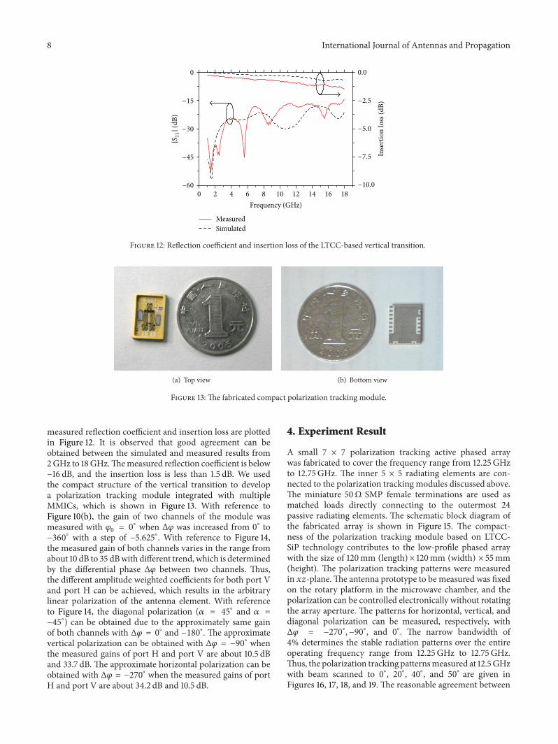

International Journal of
AerospaceEngineeringHindawi Publishing Corporationhttpwwwhindawicom Volume 2014
RoboticsJournal of
Hindawi Publishing Corporationhttpwwwhindawicom Volume 2014
Hindawi Publishing Corporationhttpwwwhindawicom Volume 2014
Active and Passive Electronic Components
Control Scienceand Engineering
Journal of
Hindawi Publishing Corporationhttpwwwhindawicom Volume 2014
International Journal of
RotatingMachinery
Hindawi Publishing Corporationhttpwwwhindawicom Volume 2014
Hindawi Publishing Corporation httpwwwhindawicom
Journal ofEngineeringVolume 2014
Submit your manuscripts athttpwwwhindawicom
VLSI Design
Hindawi Publishing Corporationhttpwwwhindawicom Volume 2014
Hindawi Publishing Corporationhttpwwwhindawicom Volume 2014
Shock and Vibration
Hindawi Publishing Corporationhttpwwwhindawicom Volume 2014
Civil EngineeringAdvances in
Acoustics and VibrationAdvances in
Hindawi Publishing Corporationhttpwwwhindawicom Volume 2014
Hindawi Publishing Corporationhttpwwwhindawicom Volume 2014
Electrical and Computer Engineering
Journal of
Advances inOptoElectronics
Hindawi Publishing Corporation httpwwwhindawicom
Volume 2014
The Scientific World JournalHindawi Publishing Corporation httpwwwhindawicom Volume 2014
SensorsJournal of
Hindawi Publishing Corporationhttpwwwhindawicom Volume 2014
Modelling amp Simulation in EngineeringHindawi Publishing Corporation httpwwwhindawicom Volume 2014
Hindawi Publishing Corporationhttpwwwhindawicom Volume 2014
Chemical EngineeringInternational Journal of Antennas and
Propagation
International Journal of
Hindawi Publishing Corporationhttpwwwhindawicom Volume 2014
Hindawi Publishing Corporationhttpwwwhindawicom Volume 2014
Navigation and Observation
International Journal of
Hindawi Publishing Corporationhttpwwwhindawicom Volume 2014
DistributedSensor Networks
International Journal of