Embed Size (px)
Citation preview
1
Layered ArchitecturesLayered Architecturesand Applicationsand Applications
CSE 3213, Fall 2010Instructor: N. Vlajic
Required reading: Garcia 2.1, 2.2, 2.3

2

3Why Layering?!
Alice wants to senda mail to Bob anda parcel to John.
City ACity A City CCity C
Alice drops off bothat the same Post Office.
Post Office looksat the addresses( city names!!! )and arranges for
proper transportation.
City BCity B
Post Office performs final delivery based
on the street and personal names.
Montreal London Paris

4Why Layering?! (cont.)
Telnet FTP NFS
PacketradioPacketradio
Coaxial cable
Fiberoptic
Application
TransmissionMedia
HTTPHTTP
Telnet FTP NFS
PacketradioPacketradio
Coaxial cable
Fiberoptic
Application
TransmissionMedia
HTTPHTTP
Intermediate layer
No LayeringNo Layering • each new application has to be re-implemented for every network technology!
LayeringLayering • intermediate layer(s) provide a unique abstraction forvarious network technologies
5
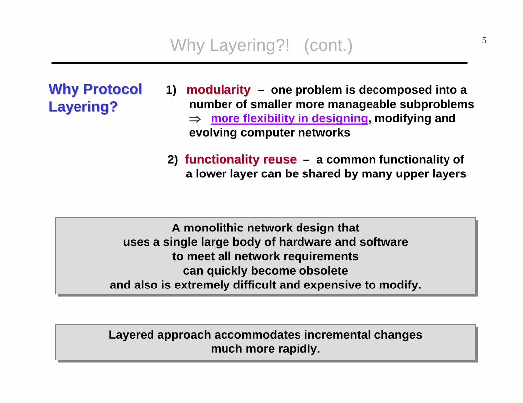
Why Protocol Why Protocol Layering? Layering?
1) modularitymodularity – one problem is decomposed into a number of smaller more manageable subproblems⇒ more flexibility in designing, modifying and evolving computer networks
2) functionality reusefunctionality reuse – a common functionality ofa lower layer can be shared by many upper layers
A monolithic network design thatuses a single large body of hardware and software
to meet all network requirementscan quickly become obsolete
and also is extremely difficult and expensive to modify.
A monolithic network design thatuses a single large body of hardware and software
to meet all network requirementscan quickly become obsolete
and also is extremely difficult and expensive to modify.
Layered approach accommodates incremental changes much more rapidly.
Layered approach accommodates incremental changes much more rapidly.
Why Layering?! (cont.)
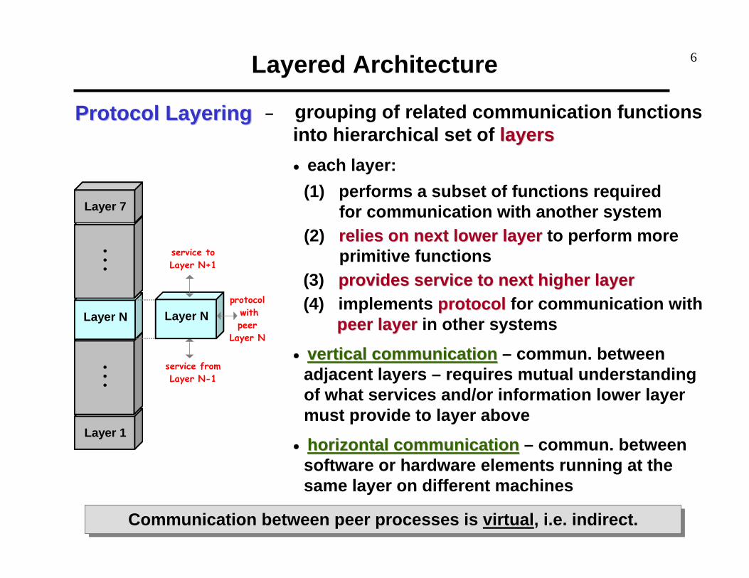
6Layered Architecture
service to Layer N+1
protocol with peer
Layer N
Layer 1
. . .
Layer N
. . .
Layer 7
service from Layer N-1
Layer N
Protocol Layering Protocol Layering – grouping of related communication functionsinto hierarchical set of layerslayers• each layer:
(1) performs a subset of functions requiredfor communication with another system
(2) relies on next lower layerrelies on next lower layer to perform moreprimitive functions
(3) provides service to next higher layerprovides service to next higher layer(4) implements protocolprotocol for communication with
peer layerpeer layer in other systems
• vertical communicationvertical communication – commun. betweenadjacent layers – requires mutual understandingof what services and/or information lower layermust provide to layer above
• horizontal communicationhorizontal communication – commun. betweensoftware or hardware elements running at thesame layer on different machines
Communication between peer processes is virtual, i.e. indirect.Communication between peer processes is virtual, i.e. indirect.

7Layered Architecture (cont.)
ProtocolProtocol – set of rules that govern data comm. between peer entities• layer-n peer processes communicate by exchanging
Protocol Data Units (PDUs)
ServiceService – can be accessed through Service Access Points (SAP’s)• layer n+1 PDU = layer n SDU (SDU = Service Data Unit)
• layer n process adds control information (header) to itsSDU to produce layer n PDU – encapsulation!
• layer n does not interpret or make use of information contained in its SDU
Layer n+1
Layer n
n+1entity
n-SAP
n+1entity
n-SAP
n entity n entity
n SDU H
H n SDU
n PDU
n+1 PDU
n+1 PDU

8
Layer n+1
Layer n
n+1entity
n-SAP
n+1entity
n-SAP
n entity n entity
n+1 PDU
H
Example [ layering – vertical vs. horizontal flow of information ]
Layered Architecture (cont.)
n SDUn PDU

9Layered Architecture (cont.)
http://www.tcpipguide.com/free/t_DataEncapsulationProtocolDataUnitsPDUsandServiceDa.htm

10OSI Model
Layered OSILayered OSIArchitectureArchitecture
• composed of 7 ordered layers
• there is fairly natural correspondence between TCP/IP & OSI layers ⇒ TCP/IP architecture canbe explained in terms of corresponding OSI layers
network support layers –deal with physical aspects ofmoving data from one deviceto another – across one link
and across the whole network
application support layers –allows communication with end-user
and interoperability amongunrelated software systems
transport layer -links upper and lower group -
ensures that what lower layershave transmitted is in a form
that upper layers can use

11OSI Model (cont.)
PeerPeer--toto--Peer Peer CommunicationCommunicationover 7 OSI Layersover 7 OSI Layers
• message moves down through layers on sendingdevice, over intermediate nodes, to receiving station,and then back up through layers
• at intermediate nodes (routers), data is pulled onlyup to network layer, so that next hop could be determined

12OSI Model (cont.)
• each layer in sending device adds its own informationto message it receives from layer above it and passeswhole package to layer just below it – reverse processoccurs at receiving device
• when data reaches physical layer, it is changed intoelectromagnetic signal and sent along a physical link
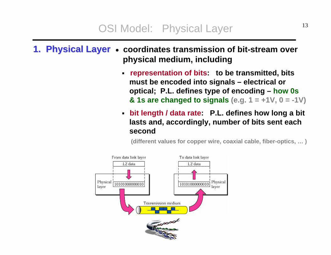
13OSI Model: Physical Layer
1. Physical Layer1. Physical Layer • coordinates transmission of bit-stream overphysical medium, including
representation of bits: to be transmitted, bits must be encoded into signals – electrical or optical; P.L. defines type of encoding – how 0s& 1s are changed to signals (e.g. 1 = +1V, 0 = -1V)
bit length / data rate: P.L. defines how long a bit lasts and, accordingly, number of bits sent each second(different values for copper wire, coaxial cable, fiber-optics, … )

14OSI Model: Data-Link Layer
2. Data2. Data--Link LayerLink Layer
The data link layer transforms the physical layer, a raw stream of bits,to a reliable link between two devices on the same network.
It makes the physical layer appear error-free to the upper layer.
The data link layer transforms the physical layer, a raw stream of bits,to a reliable link between two devices on the same network.
It makes the physical layer appear error-free to the upper layer.
sender receiver

15OSI Model: Data-Link Layer
• framingframing: The D.L.L divides the stream of bits received from the network layer into manageable data units called frames.
• physical addressingphysical addressing: The D.L.L adds a headerheader to the frame to specify the NIC address of appropriate receiver on the other side (of wire).
• error controlerror control: The D.L.L adds reliability to the physical layer by adding atrailertrailer with information necessary to detect/recover damaged or lost frames.
• access controlaccess control: When 2 or more devices are connected to same link, theD.L.L determines which device has control over the link at any given time.
• flow controlflow control: If rate at which data are absorbed by receiver is less thansender’s transmission rate, the D.L.L imposes a flow control over sender.

16OSI Model: Network Layer
3. Network Layer3. Network Layer
While the data link layer oversees the delivery of packets between two devices on the same network,
the network layer is responsible for the source-to-destination deliveryof packet across multiple networks / links.
While the data link layer oversees the delivery of packets between two devices on the same network,
the network layer is responsible for the source-to-destination deliveryof packet across multiple networks / links.
sender receiver
Routing over multiple networks:1) in min time, AND2) with min overhead.

17OSI Model: Network Layer
• logical addressinglogical addressing: The physical addressing implemented by the data linklayer handles the addressing / delivery problem locally – over a single wire.If a packet passes the network boundary another addressing system is needed to help distinguish between the source and destination network.
• routingrouting: The N.L. provides the mechanism for routing/switching packets to their final destination, along the optimal path – across a large internetwork.
• fragmentation & reassemblyfragmentation & reassembly: The N.L. sends messages down to the D.L.L. for transmission. Some D.L.L. technologies have limits on the length of messages that can be sent. If the packet that the N.L. wants to send is too large, the N.L. must split the packet, send each piece to the D.L.L, andthen have pieces reassembled once they arrive at the N.L. on destination machine.
Net 1
Net 5
Net 3Net 3
Net 2
HNet 3Net 3
G
H
H
H
GG
GG
G
Net 1Net 1
Net 2Net 2 Net 4Net 4Net 5Net 5
Ethernet LAN
ATMSwitch
ATMSwitch
ATMSwitch
ATMSwitch
ATMNetwork ATM
Switch
ATMSwitch
ATMSwitch
ATMSwitch
ATMSwitch
ATMSwitch
ATMSwitch
ATMSwitch
ATMNetwork

18OSI Model: Transport Layer
4. Transport Layer4. Transport Layer
The transport layer is responsible for process-to-process delivery of an entire message.
While network layer gets each packet to the correct computer, transport layer gets the entire message to the correct process on that computer.
The transport layer is responsible for process-to-process delivery of an entire message.
While network layer gets each packet to the correct computer, transport layer gets the entire message to the correct process on that computer.
19OSI Model: Transport Layer
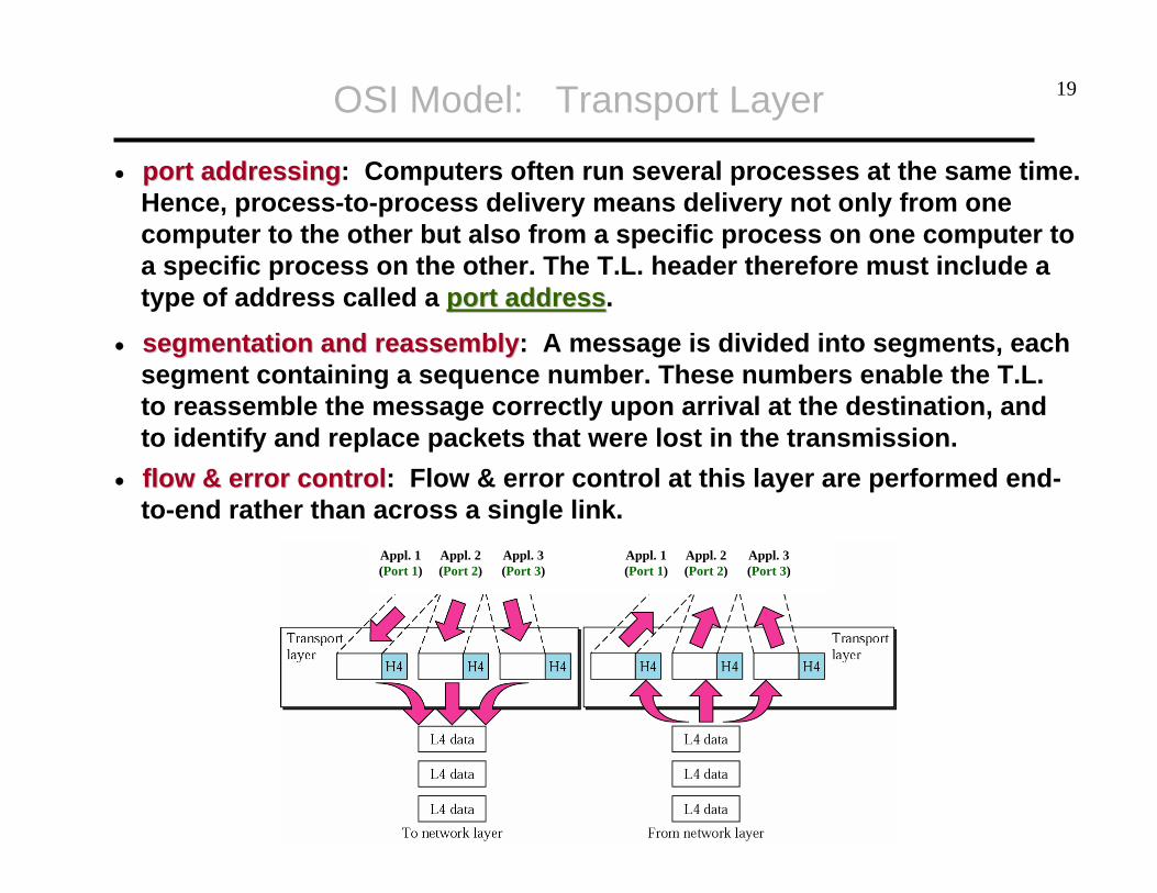
• port addressingport addressing: Computers often run several processes at the same time.Hence, process-to-process delivery means delivery not only from onecomputer to the other but also from a specific process on one computer toa specific process on the other. The T.L. header therefore must include atype of address called a port addressport address.
• segmentation and reassemblysegmentation and reassembly: A message is divided into segments, eachsegment containing a sequence number. These numbers enable the T.L.to reassemble the message correctly upon arrival at the destination, andto identify and replace packets that were lost in the transmission.
• flow & error controlflow & error control: Flow & error control at this layer are performed end-to-end rather than across a single link.
Appl. 1(Port 1)
Appl. 2(Port 2)
Appl. 3(Port 3)
Appl. 1(Port 1)
Appl. 2(Port 2)
Appl. 3(Port 3)

20
Application LayerApplication Layer (i.e. OSI Session + Presentation + Application Layer)(i.e. OSI Session + Presentation + Application Layer)
• synchronizationsynchronization: If a system is sending a large file, insert checkpoints every 100 pages to ensure that each 100-page unit is received andacknowledged independently. Thus, if a crash happens during the transmission of page 523, only pages that need to be resend are 501 to 523.
• encryptionencryption: To carry sensitive info., a system must be able to ensure privacy. Encryption transforms the original information to another form, while decryption reverses the received message back to its original form.
• compressioncompression: Data compression reduces the number of bits contained in a file – it is particularly important in the transmission of multimedia.
OSI Model: Application Layer
We want to send multimedia/video data, but network capacity limited.
We want to send private data over third-party network.
We want to send a big file to a system that occasionally crashes.
The application layer provides the actual service to the user.The application layer provides the actual service to the user.
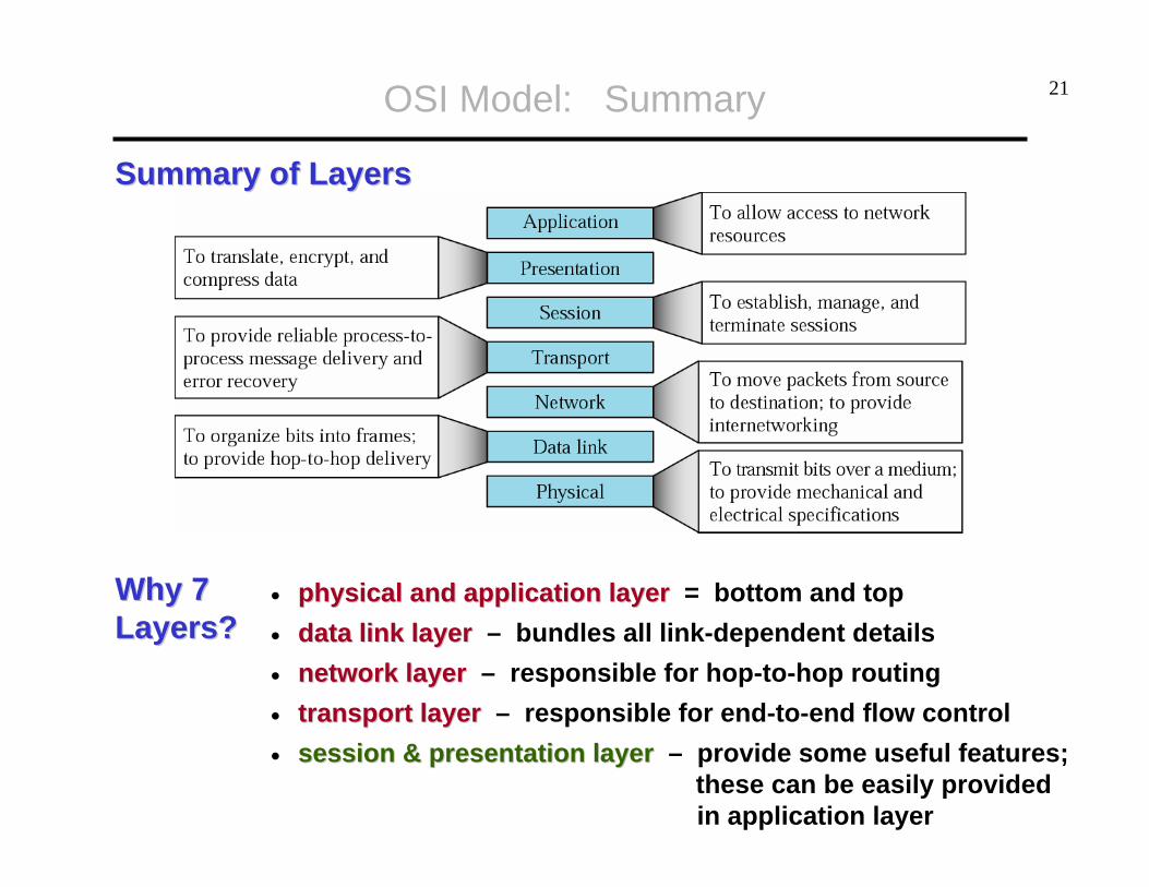
21OSI Model: Summary
Why 7 Why 7 Layers?Layers?
• physical and application layerphysical and application layer = bottom and top• data link layerdata link layer – bundles all link-dependent details• networknetwork layerlayer – responsible for hop-to-hop routing• transporttransport layerlayer – responsible for end-to-end flow control• session & presentationsession & presentation layerlayer – provide some useful features;
these can be easily providedin application layer
Summary of LayersSummary of Layers
22
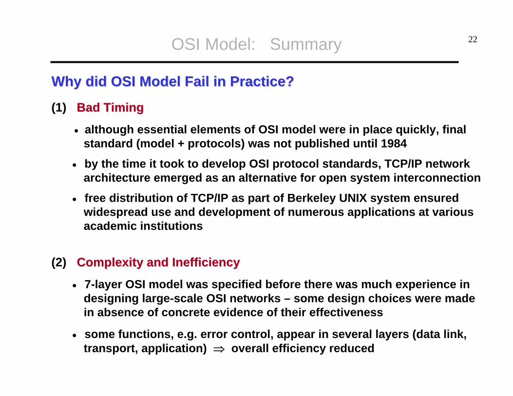
Why did OSI Model Fail in Practice?Why did OSI Model Fail in Practice?
(1) Bad TimingBad Timing
• although essential elements of OSI model were in place quickly, finalstandard (model + protocols) was not published until 1984
• by the time it took to develop OSI protocol standards, TCP/IP networkarchitecture emerged as an alternative for open system interconnection
• free distribution of TCP/IP as part of Berkeley UNIX system ensuredwidespread use and development of numerous applications at variousacademic institutions
(2) Complexity and InefficiencyComplexity and Inefficiency
• 7-layer OSI model was specified before there was much experience indesigning large-scale OSI networks – some design choices were madein absence of concrete evidence of their effectiveness
• some functions, e.g. error control, appear in several layers (data link,transport, application) ⇒ overall efficiency reduced
OSI Model: Summary

23
Internet Model and Internet Model and HourglassHourglass Protocol StackProtocol Stack
IP
Net 1 Net 2 Net 3
TCP UDP
HTTP NFSFTP TFTP
The operation of one single protocol at the network layer (IP protocol)over various networks provides independence from the
underlying network technologies. IP over anything, anything over IP!
The operation of one single protocol at the network layer (IP protocol)over various networks provides independence from the
underlying network technologies. IP over anything, anything over IP!
IP protocolacts as “glue”:everything over
IP – IP over everything!
Internet Model
Unreliableprocess-
to-processdelivery.
Reliable andin-order
process-to-processdelivery.

24Internet Model (cont.)
Addresses in TCP/IP ModelAddresses in TCP/IP Model
globally unique NIC addressused to located corresponding node on a LANeach NIC on a subnetwork mayhave different manufactures ⇒we cannot aggregate physical addresses in routing tables ⇒large networks cannot use theselarge networks cannot use theseaddresses to identify hosts !addresses to identify hosts !
globally unique logical addressused to located corresponding node in the entire Internethierarchical addresses that can be easily aggregated in routingtables ⇒ fast routing !fast routing !
locally unique logical addressused to differentiate betweenapplications sharing the sameIP address
00:07:E9:06:FD:2B
130.63.92.157
0 – 65,535

25
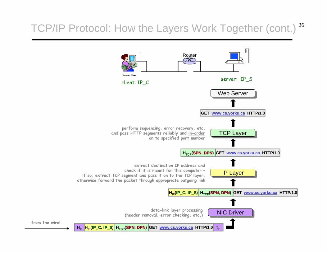
Example [ web-page retrieval – assumption: TCP connection established! ]
Web Client (Browser)Web Client (Browser)
request www.cs.yorku.ca
GET www.cs.yorku.ca HTTP/1.0
compose HTTP request
TCP LayerTCP Layer
HTCP(SPNSPN, DPNDPN)
compose a TCP segment carryingHTTP request and TCP header withsource- & destination- port-number
IP LayerIP Layer
HIP(IP_CIP_C, IP_SIP_S)
compose an IP packet carryingTCP segment and IP header withsource & destination IP address
NIC DriverNIC Driver
Router
on to the wire!
HE
GET www.cs.yorku.ca HTTP/1.0
HTCP(SPNSPN, DPNDPN) GET www.cs.yorku.ca HTTP/1.0
HIP(IP_CIP_C, IP_SIP_S) HTCP(SPNSPN, DPNDPN) GET www.cs.yorku.ca HTTP/1.0 TE
client: IP_C server: IP_S
compose an Ethernet packet carryingIP segment and Ethernet header with
source & next-hop-router NIC address
TCP/IP Protocol: How the Layers Work Together
Domain Name System
www.cs.yorku.ca
130.63.92.24
26
Router
from the wire!HE HIP(IP_CIP_C, IP_SIP_S) HTCP(SPNSPN, DPNDPN) GET www.cs.yorku.ca HTTP/1.0 TE
NIC DriverNIC Driver
HIP(IP_CIP_C, IP_SIP_S) HTCP(SPNSPN, DPNDPN) GET www.cs.yorku.ca HTTP/1.0
data-link layer processing(header removal, error checking, etc.)
IP LayerIP Layerextract destination IP address and
check if it is meant for this computer –if so, extract TCP segment and pass it on to the TCP layer,
otherwise forward the packet through appropriate outgoing link
HTCP(SPNSPN, DPNDPN) GET www.cs.yorku.ca HTTP/1.0
TCP LayerTCP Layerperform sequencing, error recovery, etc.
and pass HTTP segments reliably and in-orderon to specified port number
Web ServerWeb Server
client: IP_C server: IP_S
TCP/IP Protocol: How the Layers Work Together (cont.)
GET www.cs.yorku.ca HTTP/1.0

27TCP/IP Protocol: How the Layers Work Together (cont.)
(Source: Kurose & Ross)
applicationtransportnetwork
linkphysical
applicationtransportnetwork
linkphysical
applicationtransportnetwork
linkphysical
applicationtransportnetwork
linkphysical
applicationtransportnetwork
linkphysical
applicationtransportnetwork
linkphysical
applicationtransportnetwork
linkphysical
applicationtransportnetwork
linkphysical
networklink
physical
networklink
physical
datadata
datadata
Bonus Question [ layering – encapsulation ]
Assume two computers, situated on two distant LANs - with different data-link technologies, communicate with each other over the Internet.
Does each of these computers have to be aware of the data-link technology / protocolrun in the LAN of the other computer?
LAN1
LAN2

28
(Source: Kurose & Ross)
applicationtransportnetwork
linkphysical
applicationtransportnetwork
linkphysical
applicationtransportnetwork
linkphysical
applicationtransportnetwork
linkphysical
networklink
physical
data
data
DL1 IP data
DL2 IP data
IP data
TCP/IP Protocol: How the Layers Work Together (cont.)

29
How to determine ownIP & MAC address(es)?
www.cse.yorku.ca
How to determinethe number and
identity of intermediate routers? How to determine
IP address of another
remote machine?

30IP Utilities
IPCONFIGIPCONFIG – Microsoft Windows OS tool; UNIX/Linux equivalents: ifconfig, ip addr• in simplest form returns IP address, subnet mask, default
gateway• ipconfigipconfig /all/all – returns above and DNS hostname, physical
address, DNS and DHCP Server addresses, etc.
31IP Utilities (cont.)
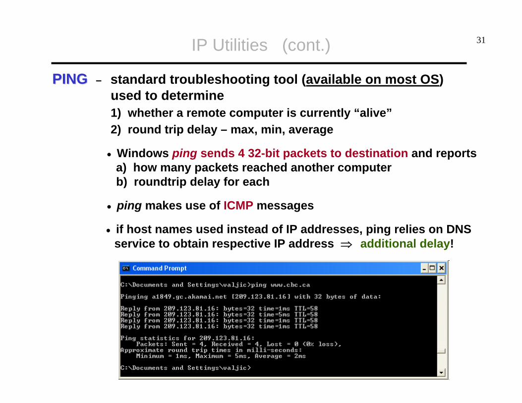
PING PING – standard troubleshooting tool (available on most OS) used to determine1) whether a remote computer is currently “alive”2) round trip delay – max, min, average
• Windows ping sends 4 32-bit packets to destination and reportsa) how many packets reached another computerb) roundtrip delay for each
• ping makes use of ICMP messages
• if host names used instead of IP addresses, ping relies on DNSservice to obtain respective IP address ⇒ additional delay!

32IP Utilities (cont.)
TracerouteTraceroute OriginOrigin – UNIX utility, but nearly all platforms have something similar• Windows utility is called tracerttracert – you can run
tracert from MS-Dos Window, by entering tracertfollowed by domain name, e.g.
tracert www.cs.yourku.ca
• tracert & traceroute have different implementation !
TracerouteTraceroute UseUse – traceroute is generally used:(1) as network debugging tool by pinpointing network
connectivity problems(2) for identifying IP addresses
Example [ traceroute ]
If you are visiting a Web site and pages are appearing slowly, you can usetraceroute to figure out where the longest delay(s) are occurring.

33IP Utilities (cont.)
Example [ traceroute www.bbc.co.uk ]

34
VisualRouteVisualRoute for Internet Performancefor Internet Performance: : http://visualroute.visualware.com/
IP Utilities (cont.)
http://www.visualware.com/resources/tutorials/tracert.html

35

36CCNA Questions
Q.1 Which layer provides logical addressing that routers will use for path determination?
A.1 Network Layer
Q.2 Which layer is responsible for converting data packets into electrical signal?
A.2 Physical Layer
Q.3 Which layer combines bits into bytes and bytes into frames, usesMAC addressing, and provides error detection?
A.3 Data-link Layer
Q.4 Which layer is used for reliable communication between endnodes over a WAN and controlling the flow of information?
A.4 Transport Layer

37CCNA Questions (cont.)
Q.5 Which fields are contained within an IEEE Ethernet frame header?(a) Source and destination MAC address.(b) Source and destination network (IP) address.(c) Source and destination MAC address and source and
destination network (IP) address.
Q.6 When data is encapsulated, which is the correct order?(a) Data, frame, packet, segment, bit.(b) Segment, data, packet, frame, bit.(c) Data, segment, packet, frame, bit.(d) Data, segment, frame, packet, bit.