Embed Size (px)
Citation preview

Capital Region Water | Administrative Offices
212 Locust Street, Suite 302 Harrisburg, PA 17101 | 717-525-7677
www.capitalregionwater.com
Request for Proposals
Professional Engineering Services for
Headworks Screening at the
Harrisburg Advanced Wastewater Treatment Facility
June 10, 2015

Request for Proposals for Professional Engineering Services Headworks Screening at the AWTF
June 10, 2015
Page 1 of 5
Invitation Capital Region Water (CRW) is requesting proposals from experienced engineering consultants for
design, bid, and construction phase services for the addition of headworks screening facilities at the
Harrisburg Advanced Wastewater Treatment Facility (AWTF).
Background CRW owns and operates the AWTF, which serves the City of Harrisburg and portions of surrounding
municipalities in Dauphin County, Pennsylvania. Operation of the AWTF commenced in 1959 and
has since underwent several upgrades. The treatment process generally includes grit removal,
primary clarification, secondary treatment consisting a high-purity oxygen activated sludge process,
and secondary clarification followed by disinfection. Construction of the AWTF Improvements
Project, a biological nutrient removal process upgrade, began in March 2014 and is expected to
reach substantial completion by the end of the year.
There is currently no screening at the AWTF headworks. The grit removal system, upgraded in 2011,
is severely affected by the lack of headworks screening and experiences blockages resulting in costly
labor and equipment down time. This also leads to buildup of debris in tanks and process
equipment throughout the AWTF.
Flows received at the AWTF are pumped from three sources, the combined Front Street Pump
Station (FSPS) and Spring Creek Pump Station (SCPS) force main and the Trewick Pump Station
(owned and operated by the Borough of Steelton). The FSPS has two multi-rake bar screen units
with 1-1/8” openings. The SCPS has one multi-rake bar screen unit with ¾” openings. The FSPS and
SCPS will both be upgraded with new ¾” opening screens over the next several years. Trewick Pump
Station flows from the Borough of Steelton are not screened.
Project Description The project will include design and construction of a building with screens and screenings handling
equipment at the AWTF. CRW recently completed a Screening Study (Attachment A) which included
recommendations for the FSPS, SCPS, and the AWTF. The project will follow recommendations
made in the Screening Study for the AWTF headworks, which includes three channels, each rated
for 40 MGD with two ¼” opening multi-rake bar screening units and one (bypass) manually-cleaned
bar rack. This provides a design capacity of 80 MGD and a total capacity of 120 MGD. The
preliminary screening facility layout is included as Appendix A to the Screening Study. AWTF flows
for years 2010 through 2014 are included as Attachment B. While annual average flows to the AWTF
headworks range from 21-24 MGD, peak instantaneous flows to the AWTF headworks can exceed

Request for Proposals for Professional Engineering Services Headworks Screening at the AWTF
June 10, 2015
Page 2 of 5
80 MGD. The new screening facility will be located in the area of the abandoned elutriation tanks.
Drawings illustrating this location and site piping are included as Attachment C.
Pre-Proposal Meeting A non-mandatory pre-proposal meeting will be held at 10:00 AM on June 24, 2015 at the Advanced
Wastewater Treatment Facility, 1662 South Cameron Street Harrisburg, PA 17104. For this meeting,
the AWTF will be accessed via the West Franklin Street entrance; do not use the Elliot Street
entrance. The meeting will be held outdoors and is an active construction site. Site access will be
limited to the area pertinent to the project.
Attendees must RSVP to Jeff Bowra, P.E. at [email protected] to receive specific
directions and meeting information.
Scope of Work Provide a detailed scope with all tasks necessary to complete the work. At a minimum, include the
following:
Project kickoff meeting and progress meetings throughout design.
Preliminary Design including survey, permitting, drawings, specifications, and construction cost
estimate.
Final Design including permitting, construction cost estimate, and bid documents including
drawings and specifications.
Bidding services including public bidding via the PENNBID website, responding to bidder
questions, issuing addenda as necessary, bid review, and recommendation of award.
Construction Administration
Resident Project Representative (RPR). Provide an hourly rate for RPR services.
Prepare, submit, and obtain approval for all permits required for the work. CRW will be responsible
for any permit fees.
Proposal Requirements Proposals should be limited to ten pages, excluding cover letter, resumes, and costs. One double-
sided sheet counts as two pages. Limit resumes to two pages each.
Proposal Summary – Provide highlights and distinguishing points of the Proposal.
Qualifications – Provide a brief firm profile and describe relevant qualifications.

Request for Proposals for Professional Engineering Services Headworks Screening at the AWTF
June 10, 2015
Page 3 of 5
Work Plan & Schedule – Provide a well-articulated description of your approach. Describe major
services and tasks to be performed including a project schedule through the bidding phase.
Identify intermediate stages when drawings and specifications will be submitted to CRW for
review.
A preliminary project schedule for the AWTF headworks screening project was included in the
Screening Study. Since that time, CRW has developed a revised schedule the consultant is
expected to meet:
Award to Consultant July 22, 2015
Notice to Proceed / Design Initiation August 1, 2015
Design Complete / Advertise for Bid February 1, 2016
Project Staffing – Provide a project-specific organizational chart and include resumes for each
team member. Include any external partners or sub-consultants and identify their scope of
work.
Project References – Provide information for three similar projects; each with reference names
and phone numbers.
Exceptions – Discuss any exceptions or requested changes that the consultant has to the
conditions of the RFP.
Cost – Provide a time and materials not-to exceed fee for all work. Provide an hourly rate for
RPR services and an estimate of RPR hours.
Note: Provide cost proposals in a separate sealed envelope, clearly labeled.
CRW is engaged in the construction of improvements to the AWTF and wishes to expedite the
completion of the AWTF headworks screening work to minimize the period that the new treatment
process is unprotected by screening facilities. Submissions that propose tangible means of
compressing the design to bid schedule will receive additional credit in CRW’s evaluation. In order
for such consideration, proposals must detail means and methods to be employed and identify the
compressed schedule explicitly. In order to discourage uninformed or capricious attempts to show
an unachievable compressed schedule, the selected consultant (should they propose a compressed
schedule) will agree to a 15% reduction of design fee if their proposed schedule is not met.
Questions
All questions regarding this Request for Proposals should be emailed to Dave Stewart, P.E., BCEE at
[email protected]. Questions should be submitted by 4:00 PM on July 6, 2015.
Telephone inquiries will not be accepted.

Request for Proposals for Professional Engineering Services Headworks Screening at the AWTF
June 10, 2015
Page 4 of 5
Submission of Proposals
Proposals must be received by 4:00 PM on July 10, 2015. Submit two (2) hard copies and one (1)
electronic copy of the Technical Proposal. Submit one (1) hard copy of the Cost Proposal in a
separate envelope, clearly labeled. Do not submit an electronic copy of the Cost Proposal.
Submit proposals to:
Mr. Dave Stewart, P.E., BCEE
Director of Engineering
Capital Region Water
212 Locust Street, Suite 302
Harrisburg, PA 17101
The electronic copy of the Technical Proposal should be submitted via email to
[email protected] or on a disc accompanying the hard copies.
Schedule Pre-Proposal Meeting - 10:00 AM June 24, 2015
Questions Due - 4:00 PM July 6, 2015
Proposals Due - 4:00 PM July 10, 2015
Award to Consultant July 22, 2015
Notice to Proceed / Design Initiation August 1, 2015
Design Complete / Advertise for Bid February 1, 2016
Selection Criteria
Evaluation and selection of Proposals will be based on responsiveness and content of all Proposal
requirements. CRW reserves the right to negotiate the final contract, scope of services, and cost
with the selected consultant. It is anticipated that award will be given at July 22, 2015 CRW Board
Meeting.
Consultants that propose a viable compressed schedule will receive additional credit in the scoring
of their proposals. Consistent with the proposed penalty, a maximum 15% credit will be applied to
proposals offering meaningfully compressed schedules that are well expressed and documented.

S:\AWTF Screening\AWTF Headworks Screening Project\RFP\2015-06-10 RFP - AWTF Headworks Screening.docx
Request for Proposals for Professional Engineering Services Headworks Screening at the AWTF
June 10, 2015
Page 5 of 5
Attachments
Attachment A
CRW Screening Study (Hazen & Sawyer), April 21, 2015.
Attachment B
Advanced Wastewater Treatment Facility Flows, 2010-2014.
Attachment C
Sheets 1, 4, 23, 31, 39, 47. Advanced Wastewater Treatment Facility Improvements Project (AECOM),
May 31, 2013.

Attachment A
CRW Screening Study (Hazen & Sawyer)
April 21, 2015

CAPITAL
REGION
WATER
HS Contract: 90168-001
Screening Study
April 21, 2015

i
|
Hazen and Sawyer
| C
Evaluation of Wastewater Pumping Stations
Table of Contents
Chapter 0 Executive Summary ......................................................................................... i
0.1 Advanced Wastewater Treatment Facility (AWTF) ................................................................................ i
0.2 Trucked-in Waste ................................................................................................................................... i
0.3 Front Street Pump Station ...................................................................................................................... i
0.4 Spring Creek Pump Station ................................................................................................................... ii
0.5 Summary of Costs and Implementation ................................................................................................ ii
Chapter 1 Introduction .................................................................................................. 1-1
1.1 Purpose and Scope ............................................................................................................................ 1-1
1.2 Study Approach .................................................................................................................................. 1-1
1.2.1 Development of Project Costs and Schedule ......................................................................... 1-1
1.2.2 Definition of Screen Types ...................................................................................................... 1-3
1.2.2.1 Bar Screens ............................................................................................................... 1-3
1.2.2.2 Perforated Plate Step Screens .................................................................................. 1-3
1.2.2.3 Rotary Drum Screens ................................................................................................ 1-4
1.2.2.4 Center Flow Band Screen ......................................................................................... 1-5
1.2.2.5 Filter Belt Screen ....................................................................................................... 1-6
Chapter 2 Existing Facilities Evaluation ....................................................................... 2-1
2.1 Advanced Wastewater Treatment Facility .......................................................................................... 2-1
2.1.1 Existing Treatment Units ......................................................................................................... 2-1
2.1.2 Trucked-in Waste .................................................................................................................... 2-1
2.1.3 Other Considerations .............................................................................................................. 2-2
2.2 Front Street Pump Station .................................................................................................................. 2-2
2.2.1 Existing Screening Capability ................................................................................................. 2-3
2.2.3 Other Considerations .............................................................................................................. 2-3
2.3 Spring Creek Pump Station ................................................................................................................ 2-3
2.3.1 Existing Screening Capability ................................................................................................. 2-4
2.3.2 Other Considerations .............................................................................................................. 2-4
Chapter 3 Recommendations for Improvements .......................................................... 3-1
3.1 General Design Considerations ......................................................................................................... 3-1

CAPITAL REGION WATER Screening Study April 21, 2015
ii
Hazen and Sawyer
|
Report - Screening Study
3.2 Advanced Wastewater Treatment Facility .......................................................................................... 3-2
3.2.1 Recommended Screens.......................................................................................................... 3-2
3.2.2 Screening Facility Conceptual Design .................................................................................... 3-4
3.2.3 Trucked-in Waste Receiving Station Conceptual Design ....................................................... 3-5
3.2.4 Alternate Configurations.......................................................................................................... 3-8
3.2.5 Opinion of Probable Cost ........................................................................................................ 3-8
3.3 Front Street Pump Station .................................................................................................................. 3-8
3.3.1 Recommended Screens.......................................................................................................... 3-8
3.3.2 Screening Facility Conceptual Design .................................................................................... 3-9
3.3.3 Alternate Configurations........................................................................................................ 3-10
3.3.4 Opinion of Probable Cost ...................................................................................................... 3-10
3.4 Spring Creek Pump Station .............................................................................................................. 3-10
3.4.1 Recommended Screens........................................................................................................ 3-10
3.4.2 Screening Facility Conceptual Design .................................................................................. 3-11
3.4.3 Alternate Configurations........................................................................................................ 3-11
3.4.4 Opinion of Probable Cost ...................................................................................................... 3-12
Chapter 4 Summary of Recommendations .................................................................. 4-1
4.1 Estimated Costs for Screening Improvements ................................................................................... 4-1
4.2 Implementation of Improvements ....................................................................................................... 4-1

CAPITAL REGION WATER Screening Study April 21, 2015
iii
Report - Screening Study
|
List of Tables Table 1-1. Initial Design Flows for Screening Facilities ............................................................................ 1-1
Table 1-2. 2013 Capital Improvements Plan Values ................................................................................. 1-2
Table 1-3. Summary of Estimating of Total Project Costs ........................................................................ 1-2
Table 1-4. Screening Facility Implementation Schedules ......................................................................... 1-2
Table 3-1. Comparison of Screen Types for AWTF ................................................................................... 3-3
Table 3-2. AWTF Screening Facility Estimated Project Cost .................................................................... 3-8
Table 3-3. Front Street PS Screening Estimated Project Cost ................................................................ 3-10
Table 3-4. Spring Creek PS Screening Estimated Project Cost .............................................................. 3-12
Table 4-1. Estimated Project Costs for Screening Facilities ...................................................................... 4-1
List of Figures Figure 1-1. Example Bar Screen Installation (Courtesy Headworks, Inc) ................................................. 1-3
Figure 1-2. Perforated Plate “Step” Screen ............................................................................................... 1-4
Figure 1-3. Internal Feed Rotary Drum Screens (Courtesy Enviro-Care) ................................................. 1-5
Figure 1-4. Center Flow Band Screens (Courtesy Ovivo Water) ............................................................... 1-5
Figure 1-5. Plastic Media Filter Belt Screens (Courtesy Parkson) ............................................................. 1-6
Figure 2-1. Existing TIW Receiving Station at the AWTF .......................................................................... 2-2
Figure 3-1. Proposed TIW Facility Layout .................................................................................................. 3-6
Figure 3-2. Potential Locations for TIW Facility ......................................................................................... 3-7

CAPITAL REGION WATER Screening Study April 21, 2015
iv
Hazen and Sawyer
|
Report - Screening Study
List of Appendices Appendix A ................................................................................................................... Conceptual Drawings
Appendix B ........................................................................ Conditions Assessment Technical Memorandum
Appendix C .................................................................. Summary of Screen Survey Technical Memorandum
Appendix D .................................................................Screenings Characterization Technical Memorandum
Appendix E ................................................................ Screen Sizing Requirements Technical Memorandum
Appendix F .............................................................. Summary of Screen Selection Technical Memorandum
Appendix G.................................................................................. Trucked-in Waste Technical Memorandum
Appendix H ...................................................................................... Opinions of Probable Construction Cost
Appendix I ......................................................................... Manufacturers’ Information and Budgetary Costs
Appendix J................................................................................................ Screening Facility Site Tour Notes

i
|
Hazen and Sawyer
| C
Evaluation of Wastewater Pumping Stations
Chapter 0 Executive Summary Hazen and Sawyer, P.C. was authorized on September 9, 2014 to prepare this Screening Study. Over the course of the ensuing meetings, tours and engineering evaluation, the following design, schedule and cost considerations are recommended:
0.1 Advanced Wastewater Treatment Facility (AWTF)
The recommended screens for the new AWTF screening facility are multi-rake bar screens with 1/4-inch openings. Two units are proposed, with a third bypass channel containing a manually-cleaned bar rack. Each channel will have with the ability to pass 40 million gallons per day (MGD), providing a total of 120 MGD of capacity and 80 MGD (peak design flow) with one unit out of service. The new facility will be constructed in the general area of the abandoned elutriation tanks. The existing hydraulics of the plant dictate that the upstream water surface will be at an approximate elevation of 323.3’ and the operating floor will be approximately 328.0’. The facility will include individual screening compactors, a common dumpster, and associated building superstructure, as shown on the figures presented in Appendix A.
The total project cost for the AWTF is estimated to be $10.25 million, based on a February 2017 midpoint of construction. The project cost includes 30% contingency, 15% engineering, and 10% legal, administrative and planning costs. For the purpose of estimating project costs, the anticipated schedule would have CRW initiate design in July 2015, begin construction in August 2016, and be substantially complete in August 2017.
0.2 Trucked-in Waste
Because the hydraulic level in the new screening facility will be several feet above grade, trucked-in waste (TIW) cannot be discharged directly upstream of the AWTF screens, and is therefore recommended to be a standalone facility. The design basis for the TIW screening facility is a 1/4-inch cylindrical fine screen. There are two potential locations for the facility: near the Chlorine Building or Thickener No. 2 (see Figure 3-2). Construction of the TIW facility is recommended to be deferred due to an estimated construction cost of $1 million and uncertainty of the relative benefits for protection of plant processes.
0.3 Front Street Pump Station
At the Front Street PS, the recommended screens are multi-rake bar screens with 3/4-inch openings, of similar configuration to the existing units. Two units are recommended to be installed in the existing channels, with a hydraulic capacity of 45 MGD per screen, in case one screen is out of service. Appurtenances associated with the screens include a common screw conveyor, a common compactor, a common dumpster, and new roof hatches for removal of existing screens and installation of new. The existing pump station building is recommended to be modified slightly to allow for greater access to equipment, to comply with current building codes, and to facilitate construction of the installation as shown on the figures presented in Appendix A.
The total project cost for the Front Street PS screens is estimated to be $3.1 million, based on an October 2016 (table 1-4) midpoint of construction. The project cost includes 30% contingency, 15% engineering, and 10% legal, administrative and planning costs. For the purpose of estimating project costs, the

CAPITAL REGION WATER Screening Study April 21, 2015
ii
Hazen and Sawyer
|
Report - Screening Study
anticipated schedule would have CRW initiate design in in May 2015, begin construction in January 2016, and be substantially complete in October 2016.
0.4 Spring Creek Pump Station
At the Spring Creek PS, the recommended screens are multi-rake bar screens with 3/4-inch openings. A second screen channel will be installed to facilitate two screens, each with a hydraulic capacity of 30 MGD, in case one screen is out of service. The existing pump station facilities are to be modified to accommodate construction of the second channel, as shown on the figures presented in Appendix A. Appurtenances associated with the screens include dedicated compactors, a common dumpster, and a new emergency generator with associated electrical modifications.
The total project cost for the Spring Creek PS screens estimated to be $7.5 million, based on an August 2018 midpoint of construction. The project cost includes 30% contingency, 15% engineering, and 10% legal, administrative and planning costs. For the purpose of estimating project costs, the anticipated schedule would have CRW initiate design in in May 2017, begin construction in February 2018, and be substantially complete in February 2019.
0.5 Summary of Costs and Implementation
Table 4-1 (repeated) below presents an estimate of the costs to implement the recommendations above for all three facilities (does not include TIW).
Table 4-1 (repeated). Estimated Project Costs for Screening Facilities Estimated Project Costs
Facility Construction Engineering and Design
Legal, Admin, and Planning
TOTAL PROJECT
AWTF $7,350,000 $1,102,500 $735,000 $9,187,500
Front Street PS $2,400,000 $360,000 $240,000 $3,000,000
Spring Creek PS $6,000,000 $900,000 $600,000 $7,500,000
TOTAL $19,687,500
From a process perspective, because there is already existing screening at the Front Street and Spring Creek Pump Stations, installation of adequate screening at the AWTF first, before the pump stations, should be a high priority for CRW. The majority of the impacts (e.g. maintenance and treatment performance) due to inadequate screening occurs at the AWTF.
From a practical perspective, CRW may be considering significant upgrades at the Front Street and Spring Creek pump stations in the near future, since much of those facilities have reached the end of their useful life. The upgrades are likely to include new pumps, piping, and valves, as well as electrical panels and controls. Architectural improvements are recommended as well; the condition assessment of the pump stations summarized in Chapter 2 could serve as a starting point for consideration of improvements at the pump stations. Coordination among the recommended screening improvements and the impending pump station upgrades is necessary. Ultimately, implementation of improvements at any facility has a reduced cost and operational impact if it can be completed with one mobilization.

1-1
|
Hazen and Sawyer
| C
Introduction
Chapter 1 Introduction 1.1 Purpose and Scope
Capital Region Water authorized Hazen and Sawyer, P.C. to perform a Screening Study on September 9, 2014, based upon our technical and cost proposal dated June 25, 2014. As stated in the original Request for Proposal, “CRW owns and operates sewer collection, conveyance and treatment facilities servicing the City of Harrisburg and portions of neighboring municipalities.”
The overall purpose of this study is to establish the Basis of Design for large solids removal at the Advanced Wastewater Treatment Facility (AWTF), the Trucked in Waste (TIW) receiving station, the Front Street Pump Station (FSPS), and the Spring Creek Pump Station (SCPS). Each location has different flows, functionality and demands, and ultimately will have different recommendations for successful installation. Table 1-1 provides the summary of flows as presented in the proposal.
Table 1-1. Initial Design Flows for Screening Facilities AWTF FSPS SCPS
Design Avg/Peak (MGD) 37.7/45 21.6/43.2 10.0/28.9
2013 ADF (MGD) 21.6 14.9 4.8
2013 Peak (MGD) >80* 33.6 20.9
*Combined peak flows to the AWTF headworks can exceed 80 MGD
The Study will establish design criteria, evaluate options for accomplishing the desired screening/removal, and ultimately make recommendations for the implementation of screens and associated equipment at all four locations. In developing the basis of design for these facilities, project costs and project schedule are established.
1.2 Study Approach
1.2.1 Development of Project Costs and Schedule
In order to develop a credible project cost and schedule, this Study considers the existing conditions of facilities, the design goals of the intended facilities, and a variety of issues including the maintenance and operation of existing facilities during construction. Capital Region Water has established four projects in its long term capital improvements plan (CIP) along with a general goal to have the new facilities commissioned in 2017. From the CRW CIP, we note the following items:

CAPITAL REGION WATER Screening Study April 21, 2015
1-2
Hazen and Sawyer
|
Report - Screening Study
Table 1-2. 2013 Capital Improvements Plan Values Project CIP Allowance (2013)
AWTF Screen Building & Systems $ 4,100,000
TIW Receiving Station* $ 2,300,000
Front Street Pump Station $ 6,500,000
Spring Creek Pump Station $ 4,100,000
* Scope to be determined during the detailed design of the screening facility. Construction would occur as part of the AWTF Headworks screening project
At the concept level, Hazen and Sawyer typically develops a cost estimate based upon the anticipated work in current dollars. To that value, 30% contingency is added which results in the opinion of probable construction cost (OPCC). This value is then inflated to the mid-point of the anticipated construction schedule and an accuracy rate of -15% to +20% is applied – resulting in an AACE Class 4 estimate. To develop the project budget, an allowance of 25% for Engineering, Legal, Administrative and Planning (ELAP) is added to the OPCC for total project cost. See Table 1-3 for a summary.
Table 1-3. Summary of Estimating of Total Project Costs Term Basis
Construction Cost Estimate Construction costs plus 30% design contingency (in today’s dollars)
Opinion of Probable Construction Cost (OPCC)
Probable construction cost, escalated to the mid-point of construction
Accuracy Range – Low OPCC x 85%
Accuracy Range – High OPCC x 120%
ELAP 25% x OPCC
Total Project Cost OPCC + ELAP
To escalate the construction cost estimate to the mid-point of the actual construction project, we have generally established the project schedules presented in Table 1-4.
Table 1-4. Screening Facility Implementation Schedules Facility AWTF TIW FSPS SCPS
Study Complete April 2015 April 2015 April 2015 April 2015
Initiate Design July 2015 July 2015 May 2015 May 2017
Design Complete June 2016 June 2016 January 2016 Dec 2017
Start Construction August 2016 August 2016* April 2016 February 2018
Construction Substantially Complete
August 2017 August 2017* April 2017 February 2019
Mid-Point for Estimate February 2017 February 2017 October 2016 August 2018
*The TIW receiving station is independent of other facilities and can be deferred

CAPITAL REGION WATER Screening Study April 21, 2015
1-3
Report - Screening Study
|
1.2.2 Definition of Screen Types
The types of screens considered for the CRW facilities are presented below for reference. This summary is not intended to describe all types of screens in detail, but generally categorizes the different products on the market according to their configuration, purpose, and performance.
1.2.2.1 Bar Screens
Bar screens consist of individual bars vertically arranged with a specific spacing between the bars. Cleaning rakes are used with teeth that engage the bars and remove the solids that have been trapped. Bar screens can be provided with single or multiple cleaning rakes. Multi-rake bar screens (see Figure 1-1) are more commonly installed in recent years, and are typically available in opening sizes of 1/4” to 2”.
Figure 1-1. Example Bar Screen Installation (Courtesy Headworks, Inc)
Multi-rake bar screens are known for their sturdy construction and ability to handle large differential heads. They are often made entirely out of stainless steel. However, they also have lower capture rates than other screens due to limitations on tightness of the bar spacing. Prominent manufacturers of multi-rake bar screens in the eastern US include:
Headworks (Mahr Bar)
Duperon (Flex Rake)
Vulcan (VMR)
Huber (RakeMax)
1.2.2.2 Perforated Plate Step Screens
Perforated plate screens use a thin metal plate that is mounted to chains (or other type of sprocket drive) on each side of the screen frame. The plates are installed with “steps” (see Figure 1-2) to collect material and transport it up to a collector by moving the entire

CAPITAL REGION WATER Screening Study April 21, 2015
1-4
Hazen and Sawyer
|
Report - Screening Study
plate. Perforated plate screens are available with smaller openings (1/8” or 3 mm) than bar screens and have a higher capture rate due to limitation of passage in the vertical direction. Screenings are typically removed with a brush and/or spray water, and some “carryover” of screenings on the plate has been known to occur due to material staying on the screen.
These screens rely partially on a mat of screenings to remove fibrous material, which results in an increased headloss and greater potential for blinding. The stainless steel panels are susceptible to hairpinning because the plate is so thin and hairs become woven into the plate holes.
Figure 1-2. Perforated Plate “Step” Screen
Prominent manufacturers of perforated plate step screens in the eastern US include:
Parkson
Headworks
Hydro-Dyne
Andritz
1.2.2.3 Rotary Drum Screens
There are two versions of the rotary drum screen: internal feed and external feed. The internal feed drum screen has wastewater fed into a distribution pan inside the rotating drum, which has a bar, perforated plate, or mesh screen. Screenings are conveyed to the discharge point using internal auger flights. The screened wastewater discharges through the back of the screen (see Figure 1-3).

CAPITAL REGION WATER Screening Study April 21, 2015
1-5
Report - Screening Study
|
Figure 1-3. Internal Feed Rotary Drum Screens (Courtesy Enviro-Care)
Internal feed rotary drum screens are very commonly used at smaller wastewater plants and septage receiving stations; however, they are also used at larger plants. The advantage of these screens is lower headloss than those with a steeper incline and same opening size. Conversely, they require a larger footprint to install. They are available with fine openings, i.e. 0.5 mm (0.02”) to 6 mm (1/4”). Prominent manufacturers include Huber (RotaMat) and Enviro-Care.
External feed systems flow through the drum screen walls and discharge through the center of the screens. External scrapers are used to remove screening material for disposal. External feed rotary drum screens are typically used for very fine screening at plants that do not have primary clarifiers.
1.2.2.4 Center Flow Band Screen
Center flow band screens have a traveling screening belt that is oriented parallel to its channel. These screens rely on flow entering through the front of the screen and discharging through the screen panels on both sides. Screenings are carried vertically at a 180° angle by teeth or “shelves” to the discharge at the top; lost screenings fall into the center of the screen and are contained.
Figure 1-4. Center Flow Band Screens (Courtesy Ovivo Water)
Center flow band screens are commonly used for fine screening applications (1 mm to 1”) such as raw water intakes for drinking water plants, but they are also used in wastewater applications. They impart a relatively high headloss and have a greater potential for blinding compared to other types of screens. However, they do have relatively low maintenance requirements since the drive and sprockets are accessible

CAPITAL REGION WATER Screening Study April 21, 2015
1-6
Hazen and Sawyer
|
Report - Screening Study
from the operating deck and there are no lower bearings. Prominent manufacturers include Headworks, Hydro-Dyne (Triden), and Ovivo (Brackett Green).
1.2.2.5 Filter Belt Screen
These screens use a two-stage screening method allowing the screen to filter out solids much smaller than the screen opening. This is achieved through coarse filtration on the leading edge of the belt, with fine screening on the recessed face of the belt. As the tip of one row of elements passes between the shanks of the elements on the lower row, the elements are cleaned of screening material. A rotating brush or spray water are also used to remove solids that might remain on the belt.
Figure 1-5. Plastic Media Filter Belt Screens (Courtesy Parkson)
Similar to step screens, filter belt screens rely partially on a mat of screenings to collect fibrous material. Accordingly, there is also a greater carryover of screenings and a higher capture rate of fine material. These screens often have the greatest headloss for a particular application, and cannot withstand a great head differential due to the potential for the plastic teeth to break. Filter belt screens are available with openings sized between 1 mm and 4”. The most prominent manufacturer of this type of screen is Parkson (AquaGuard), but Hydro-Dyne (Triden) and Andritz also offer similar equipment.

2-1
|
Hazen and Sawyer
|
Report - Screening Study
Chapter 2 Existing Facilities Evaluation This chapter includes a summary of key findings from the condition assessment at each facility. See Appendix A for additional details.
2.1 Advanced Wastewater Treatment Facility
The Advanced Wastewater Treatment Facility (AWTF) is rated for 37.7 million gallons per day (MGD) and currently receives average flows of 20-25 MGD. With a combined sewer system, the peak flows approach four times the average flow and occasionally exceed 80 MGD. Accordingly, the design flow for this study was provided by CRW as 80 MGD.
2.1.1 Existing Treatment Units
The AWTF currently has no screening facilities. Preliminary treatment includes vortex grit removal, which is followed by primary clarifiers, high purity oxygen secondary treatment, secondary clarifiers, and chlorine disinfection. The plant is currently undergoing a major upgrade to implement biological nutrient removal (BNR), which is scheduled for completion in April 2016.
For years, the grit removal facilities and primary clarifiers have been experiencing clogging and other maintenance issues due to rags, flattened cans and bottles, wrappers, and other non-dispersible materials that could be screened upstream with the proper equipment. Although the screens at the pump stations provide some limited protection from these materials, finer screening at the AWTF is needed.
2.1.2 Trucked-in Waste
Due to hydraulic reasons, the AWTF currently receives trucked-in waste (TIW) on the downstream side of the grit removal facilities, so there is no protection from grit and debris for the downstream treatment units. The existing facilities include dual ports for septage haulers to connect and discharge the contents of their trucks by gravity (see Figure 2-1). The TIW then flows to the primary clarifiers without pretreatment.

CAPITAL REGION WATER Screening Study April 21, 2015
2-2
Hazen and Sawyer
|
Report - Screening Study
Figure 2-1. Existing TIW Receiving Station at the AWTF
The water surface elevation at the existing grit removal facilities is several feet above grade, which does not allow gravity discharge by the trucks from street level. A new screening facility for the AWTF would be upstream of grit removal, so the water surface elevation would be even higher above grade. Therefore, the only way to incorporate TIW into the new screening facility would be to install a TIW receiving station with pumping capability and potentially separate screening. Alternatives for this separate TIW receiving station are discussed in Chapter 3.
2.1.3 Other Considerations
The area of the AWTF site designated for a new screening facility (see Figure A-1) has minimal existing buried utilities that are still in service. Some demolition of abandoned utilities and structures is expected. The incoming force mains from the Spring Creek Pump Station and Steelton discharge through a common 54” force main into a diversion box before flowing by gravity into the grit removal facilities. A new screening facility would intercept the flow in the primary 54” force main and likely discharge to the same diversion box upstream of grit removal. Accordingly, the additional headloss imparted by the new screening facility (approximately 3.2 feet at peak flows) will impact the performance of the upstream pumps that feed into the 54” force main.
2.2 Front Street Pump Station
The Front Street Pump Station was originally constructed in 1959 and currently conveys an average daily flow of 14.9 MGD to the AWTF. The peak discharge flow from the station is 45 MGD. This section contains a brief description of the existing Front Street Pump Station; a Conditions Assessment Report is provided in Appendix B and provides a more in-depth overview and assessment of the Front Street Pump Station.

CAPITAL REGION WATER Screening Study April 21, 2015
2-3
Report - Screening Study
|
2.2.1 Existing Screening Capability
The station currently contains two FMC multi-rake bar screens that are located in dedicated five foot wide screening channels just prior to the pump station wet well. The screens are provided with 1-1/8-inch openings in between the bars. The screens date back to the original construction of the station in 1959. A common belt conveyor and a single ram screenings compactor were installed in a 1982 upgrade. The ram compactor discharges compacted screenings into a 2 cubic yard dumpster located in the garage, which is adjacent to the screen chamber. The screens, conveyor and ram compactor have all reached the end of their useful lives and are in need of replacement.
The screen chamber has two access locations: a set of double doors and stairway from the operating floor above and a single exterior door with direct access on the south side, next to the Susquehanna River. The interior door locations do not provide the NFPA-recommended separation between the Class I, Division I screen chamber and the operating floor, which houses the electrical equipment for the station.
2.2.3 Other Considerations
Mechanically, the Front Street Pump Station is much the same as it was after the 1959 construction. The station has four centrifugal sewage pumps that discharge through a 48-inch cast iron force main that conveys the wastewater to the AWTF for treatment. The existing isolation valves are actuated using a centralized hydraulic control system that is prone to leaks and maintenance issues.
Architecturally, the station has issues with exterior bricks that are being pushed outward on front of the station and with interior glazed block that has cracked. Fall protection is provided for railings and stairways. However, they are not OSHA required 42-inch high railings with toe plates, since the station predates the current building code that governs building occupancy and egress requirements. Additional egress modifications to the lower floors will be required if the station is significantly upgraded.
The station has outdated electrical equipment that has also reached the end of its useful life. The instrumentation and controls appear to be a mixture of original equipment that have been minimally upgraded as needed for repairs in recent years.
The HVAC system is outdated and does not meet NFPA 820 or the International Mechanical Code 403. The entire HVAC system should be considered for replacement with any significant upgrade to the station.
2.3 Spring Creek Pump Station
The Spring Creek Pump Station was originally constructed in 1959, and it currently conveys average daily flows of 4.8 MGD to the AWTF with a peak discharge flow of up to 30 MGD. This section contains a brief description of the existing pump station; a Conditions Assessment Report is provided in Appendix B and provides a more in-depth overview and assessment of the station.

CAPITAL REGION WATER Screening Study April 21, 2015
2-4
Hazen and Sawyer
|
Report - Screening Study
2.3.1 Existing Screening Capability
The station is provided with a single FMC multi-rake bar screen that is located on the east side of the pump station. The bar screen has 3/4-inch openings and was installed during the 1982 station upgrade. The screenings are discharged directly into a 2 cubic yard dumpster; the screen and dumpster are located in a fiberglass enclosure.
The existing bar screen is a vertical installation, and the bars extend up out of the channel approximately two feet. As the rakes that engage the bars travel upward, large screened material such as bottles and cans often fall off the rake, sometimes going past the screen and into the wet well.
On the west side of the station are the original barminutors that were previously used to protect the pumps from material coming into the station. The barminutors are located in parallel channels but are no longer functional.
2.3.2 Other Considerations
The station has three vertical centrifugal sewage pumps that discharge through a 24-inch line into the 48-inch cast iron Front Street PS force main, which runs adjacent to the Spring Creek PS. The pumps and check valves were replaced in the 1982 upgrade, but all of the other piping and isolation valves are original to the station. All are considered to be beyond their useful lives.
Architecturally, the station has a few broken windows and paint that is peeling off the walls and ceilings. These issues should be addressed in any significant upgrade project.
Similar to the Front Street PS, the Spring Creek PS still operates with some of the original electrical equipment, which is outdated and is nearing the end of its useful life. The existing electrical service is undersized for the station to operate under full load capacities. The instrumentation and controls appear to be a mixture of original equipment that have been minimally upgraded as needed for repairs in recent years.
The HVAC system is outdated and does not meet NFPA 820 or the International Mechanical Code 403. The entire HVAC system should be considered for replacement with any type of upgrade to the station.

3-1
|
Hazen and Sawyer
|
Report - Screening Study
Chapter 3 Recommendations for Improvements To establish some background information for use in recommending screens for the CRW facilities, a multi-layered data collection effort was conducted, as summarized below:
Survey of similar utilities in Pennsylvania and other states regarding their screening facilities
Site visits with CRW staff to select facilities in the Capital Region with varying types of screens
Development of a subjective matrix to select the recommended screen types
With the recommendations for improvements below, we have presented a brief description of key conclusions from these efforts; more in-depth discussions can be found in the appendices as noted.
3.1 General Design Considerations
During the study CRW and Hazen and Sawyer visited several screen installations to gather information and recommendations by other plant operators. Several of these recommendations were directly applicable to the CRW design, and were strongly considered in the conceptual design of the facilities. These considerations are listed below:
Enclosure of the equipment to prevent weather-related issues. In particular, at the City of York wastewater treatment plant (WWTP), the Huber bar screens were inoperable during our site visit due to freezing. Similarly, at the Springettsbury Township WWTP, the Hydro-Dyne center flow screens were inaccessible for maintenance and inspection due to ice buildup on the removable inspection panels.
Consideration of maintenance access and history with certain equipment. At the Springettsbury Township WWTP, the Hydro-Dyne center flow screen with 3 mm openings had frequent interruption in service due to maintenance and repair issues. This maintenance issue was made worse by the fineness of the screening and the lack of a bypass channel around the screens. Conversely, the Duperon screens at the City of Lebanon Authority WWTP had very little maintenance and repair in their eight years of service.
Proper selection of equipment for handling grease, particularly to prevent blinding of perforated surfaces in the compactor units. This blinding was a concern noted with the Duperon compactors at the City of Lebanon Authority WWTP, but was alleviated with a custom-built flushing system devised by the Authority operators.
Proper selection of screens at the pump stations (without a fixed bottom travel point) to prevent bricks and other debris from jamming and inhibiting rake travel. This jamming from sewer bricks was a maintenance issue at the City of Lancaster outlying pump stations with Headworks Mahr Bar screens that had lower bearings.
Avoidance of plastic screens that experience teeth breaking and bending of side plates. Resilience of the Parkson plastic filter belt screen at the Borough of New Holland WWTP was a concern.

CAPITAL REGION WATER Screening Study April 21, 2015
3-2
Hazen and Sawyer
|
Report - Screening Study
Method of screenings removal from step screens (e.g. perforated plate) and filter belt screens. At the Fort Indiantown Gap WWTP, the spray water that cleans the perforated plate step screen was a significant water demand, and did a relatively good job of cleaning. However, some carryover of material to the downstream side of the screen was observed. The operator at this plant recommended the use of plant water for screening to avoid paying for potable water. The rotating brush that is also used to clean the screen was out of service due to a malfunctioning motor support bracket and bearing.
3.2 Advanced Wastewater Treatment Facility
3.2.1 Recommended Screens
Many facilities with BNR treatment requirements have implemented fine screening (1/4” openings or smaller) and minimized or eliminated the use of primary clarification. By minimizing primary treatment, more carbon (typically measured in the form of biochemical oxygen demand, or BOD) is available for denitrification downstream of the aeration process. Also, finer screening provides better protection for downstream equipment and, in turn, reduced maintenance. However, because the AWTF uses high purity oxygen for secondary treatment, the likelihood of BOD being available downstream of the aeration process is low, and the primary clarifiers are expected to remain in service. In fact, the ongoing facility improvements project is incorporating chemically enhanced primary treatment (CEPT), which will further improve primary clarifier performance.
Because the AWTF has downstream grit removal and primary clarification, the primary criteria in determining screen opening size are protection of downstream equipment and maintenance mitigation. As summarized in Appendix E, the downstream equipment recommendations indicate a maximum opening size of 3/8”. Since the AWTF receives flow from a combined sewer system, there is potential for a large amount of mixed debris entering the plant during wet weather. Overly fine screening during these wet weather events could result in excess wear on the equipment due to constant cleaning of the screens. A review of several similar size facilities (flows greater than 20 MGD) with combined sewer systems revealed an average screen opening size of 1/2”, as presented in Appendix C.
Screens with openings smaller than 1/4” typically require a greater flow of wash water for cleaning, and impart a greater headloss per screen than those with larger openings. The quantity of screened material associated with screens finer than 1/4” could also be much greater than those with larger openings, because some of the material retained would include grit and organics that would otherwise be removed in the grit removal facilities and primary clarifiers. Because the availability of grit removal and primary clarification downstream reduces the benefits of finer screening, the minimum potential screen opening size was determined to be 1/4”. For comparison of different types of screens, budgetary cost proposals were obtained from several manufacturers based on an opening size of 3/8”, and they are included in Appendix I. A summary of the information is included in Table 3-1.

3-3
|
Hazen and Sawyer
|
Report - Screening Study
Table 3-1. Comparison of Screen Types for AWTF Manufacturer Headworks Parkson Parkson Hydro-Dyne Duperon Huber Huber
Model MS1
(Bar Screen) Aquaguard (Filter Belt)
Aquaguard PF (Perf. Plate)
Hydro-Flo (Center Flow)
FlexRake M (Bar Screen)
RakeMax (Bar Screen)
EscaMax (Perf. Plate)
Spacing (in) 3/8 1/41 1/41 3/8 3/8 3/8 3/8 Flow per Screen (MGD) 40 40 40 40 40 40 40 Quantity 3 3 3 3 3 3 3 Total Flow (MGD)2 120 120 120 120 120 120 120 Channel Width (ft) 5 5 5 73 5 5 5 Channel Depth (ft) 11 11 11 11 11 11 11 Angle (deg) 85 75 75 90 75 75 60 Headloss (in) 6 41 20 7 6 13 22 Assumed Blinding 50% 30% 30% 50% 50% 50% 50%
Budgetary Cost Quote $607,414 $930,000 $930,000 $625,000 $463,000 $575,000 $685,000
Other Considerations Washer/Compactor $171,086 $225,000 $225,000 $150,000 $240,000 $185,000 $185,000 Wash Water Demand per screen (gpm) 10 25 40 48 5 16 36
Total Budgetary Cost $778,500 $1,155,000 $1,155,000 $775,000 $703,000 $760,000 $870,000
NOTES: 1. Parkson does not offer a filter belt screen with 3/8” openings (only 1/4” or 5/8”). They provided a perforated plate budgetary proposal with the same size
openings for consistency in their submittal. 2. 80 MGD total firm screening capacity (with one of the largest units out of service) 3. Channel width at center flow screen is 7 ft to accommodate perpendicular flow pattern

3-4
|
Hazen and Sawyer
|
Report - Screening Study
Table 3-1 shows a clear difference in operating conditions between the various types of screens, particularly regarding headloss and wash water demand. The lower capital cost and O&M for bar screens are notable benefits, although the improved removal associated with filter belt and perforated plate screens would provide enhanced protection for downstream equipment and processes. Note that the center flow screen would also result in a greater cost than the bar screens due to the greater channel width impacting the overall size of the facility.
The filter belt and perforated plate screens have a vertical limitation on size to improve screening of long, thin items that could potentially go through a bar screen. CRW staff has noted that this vertical limitation is critical, because they have noticed a large amount of long, thin items (e.g. flattened cans and bottles) flowing through to the treatment processes. However, as a conventional bar screen builds up a “mat” of debris, a vertical limitation is provided by the other debris collecting on the screen. In addition, the orientation of a long, thin item such as a flattened aluminum can would have to be almost perfectly vertical at the point of interception to penetrate through a bar screen with 1/4” or 3/8” openings. The frequency of this situation, in our estimation, is not worth the additional capital and O&M costs associated with filter belt, perforated plate, or center flow screen configurations. Accordingly, we recommend multi-rake bar screens with 1/4” openings for the AWTF.
With multi-rake bar screens, one of the primary equipment design questions is whether or not to have a lower bearing below the water surface. Including the lower bearing (or wear plates at a fixed point at the bottom of the rake travel) adds rigidity to the rake travel and, with some equipment, requires draining the channel for regular maintenance. Screens with no fixed point at the bottom of the rake travel use the weight of the rakes and brackets, as well as the angle of installation, to keep the rakes in alignment. The advantage of this is that a large item at the screen (e.g. a 2 x 4, rocks, tires) will not inhibit travel of the rakes; the rakes will simply move over it until the item is in proper position for removal or is removed manually. Conversely, a lower bearing on a screen can be a potential source for jamming from bricks and debris, as observed at the City of Lancaster, which has brick sewers. CRW also has many brick sewers in their collection system, as well as storm flow from combined sewers, which can convey large debris. For these reasons, multi-rake bar screens without a fixed point at the bottom of the rake travel (e.g. Duperon FlexRake) are recommended for the CRW facilities, particularly at the Front Street and Spring Creek pump stations.
3.2.2 Screening Facility Conceptual Design
Figures A-1 through A-4 in Appendix A present a conceptual layout for the proposed screening facility at the AWTF. The screens are arranged in three channels, with the third channel containing a manually-cleaned bar rack. Each channel has a hydraulic capacity of 40 MGD, for a total facility capacity of 80 MGD with one unit out of service. The hydraulic profile through the facility was calculated assuming a water surface elevation of 320.0 at the downstream diversion box (peak flow conditions upstream of the grit chambers).
The screen channels were sized to allow a minimum velocity of 1.5 ft/sec during average flows with one channel in service to keep material in suspension, and no more than 3 ft/sec with two channels in service during peak flows to minimize turbulence and allow an even distribution of screenings. As the project progresses into detailed design, the channel width could be reduced to improve

CAPITAL REGION WATER Screening Study April 21, 2015
3-5
Report - Screening Study
|
hydraulics, but for this study we wanted to ensure that sufficient space was included in the building footprint.
During normal dry weather conditions, one screen would be sufficient to handle all of the flow, and the other two channels would be isolated by closing the automated gates. Similarly, during high flow conditions, the gates at the standby channel(s) would automatically open if the water level differential at the online screen reached a certain level. We would also propose a control strategy where the primary screen receiving flow alternates on a regular basis to facilitate balanced wear on equipment.
Because there is sufficient room in this new facility, dedicated washer/compactors are included for each screen, and the compacted screenings are transported directly to a 40 CY dumpster. Sufficient room has been provided in the dumpster bay to shift the dumpster for even distribution of screenings within. A winch mounted on the floor on the south side of the facility would be included in the design to adjust the position of the rolling dumpster. A davit crane will also be provided to transport equipment and materials between the upper and lower levels.
Architectural and HVAC aspects of the facility would be designed to treat the screen area as a Class I, Division I space. The electrical/control room would be isolated from the classified space by an air lock and would have a separate entrance from the outside. Windows would be provided in the wall between the electrical/control room and the screen area to facilitate operator communication.
3.2.3 Trucked-in Waste Receiving Station Conceptual Design
As presented in Chapter 2 and Appendix G, TIW would require separate screening and pumping if CRW chose to discontinue their current practice of discharging TIW downstream of the grit chambers. There are two locations on the AWTF site that were considered for a new TIW facility. The approximate footprint for the TIW facility was based on the layout in Figure 3-1, and the two potential locations are presented in Figure 3-2.

CAPITAL REGION WATER Screening Study April 21, 2015
3-6
Hazen and Sawyer
|
Report - Screening Study
Figure 3-1. Proposed TIW Facility Layout
The overall size of the TIW facility is about 55 ft x 45 ft, including the dual truck bays. The septage screen to be considered would likely be a cylindrical screen/washer/compactor unit with same size openings as the other screens in the AWTF facility. The pumps to handle the screened TIW would likely be self-priming pumps with the ability to discharge upstream of the grit chambers or another location in the plant (e.g. denitrification tanks). One advantage of this type of facility is that the TIW could also be routed directly to the anaerobic digesters if appropriate (e.g. high strength waste).
Truck Bay No. 1
Truck Bay No. 2
Pump Room
Wet Well No. 2 (Below)
Wet Well No. 1 (Below) Office
Septage Screen

CAPITAL REGION WATER Screening Study April 21, 2015
3-7
Report - Screening Study
|
Figure 3-2. Potential Locations for TIW Facility
While there appears to be sufficient area on site to construction a new TIW facility, we anticipate the construction cost to be approximately $1 million. CRW staff has indicated that the benefits of this facility may not warrant the additional cost, so this concept has been deferred.
TIW Location No. 1
TIW Location No. 2
Proposed AWTF Screening Facility

CAPITAL REGION WATER Screening Study April 21, 2015
3-8
Hazen and Sawyer
|
Report - Screening Study
3.2.4 Alternate Configurations
An alternate configuration considered during the study included locating the TIW facility and screening facility in the same area, where the screening facility is proposed currently. This alternative was eliminated during a progress meeting due to constructability concerns and accommodation of truck accessibility in the area. The project team determined that there simply was not enough space in the proposed area to include both facilities.
Other design elements for the AWTF screening facility may be considered during detailed design but are not included in the concept drawings. These considerations include:
Reduction of area for the screenings dumpster, since size of dumpster could be decreased if emptying frequency is increased.
Odor control (likely wet scrubber type for H2S removal) pulling foul air directly from the influent and effluent channels, which would be covered with solid plates instead of grating. These locations of foul air withdrawal could reduce the size of an odor control system, if odor control is determined to be necessary.
3.2.5 Opinion of Probable Cost
A detailed Opinion of Probable Construction Cost (OPCC) for the proposed AWTF screening facility is included in Appendix H. The OPCC should be considered a Class 4 (concept study) estimate in accordance with the American Association of Cost Engineers (AACE) guidelines. Table 3-2 presents a summary of the total project cost.
Table 3-2. AWTF Screening Facility Estimated Project Cost Description Cost
Construction Cost (see Appendix H) $7,350,000
Engineering (Design and Construction) Cost at 15% $1,102,500
Legal, Administrative, and Planning at 10% $735,000
TOTAL $9,187,500 NOTE: TIW Facility (approx. $1 million construction cost) not included
3.3 Front Street Pump Station
3.3.1 Recommended Screens
The existing Front Street PS has 1-1/8” opening bar screens, which were the basis of design for the channel sizes and other structural features impacting hydraulics within and upstream of the wet well. The existing configuration limits the possibilities of changing the screen type. Center flow screens were not a possibility due to the structural modifications needed to accommodate the change in flow path. Filter belt and perforated plate screens with greater wash water requirements were eliminated because the only water supply at the pump station is potable water. The existing

CAPITAL REGION WATER Screening Study April 21, 2015
3-9
Report - Screening Study
|
configuration with limited access for maintenance makes multi-rake bar screens preferred, especially because the collection system includes combined sewers.
During the course of the study, the project team entertained the idea of increasing the screen opening size to 1-1/2” to reduce the quantity of screenings by up to 40%. CRW noted that reducing screenings at the pump stations by that amount is not a priority (as discussed in Appendix D). Because CRW staff visit the pump stations on a regular basis, emptying the screenings dumpster frequently is not a significant effort.
Conversely, decreasing the opening size of the screens to 3/4” was also evaluated to match the opening size of the screens at Spring Creek PS. Hazen and Sawyer has determined that this decrease in opening size would result in a marginal increase in headloss (about 2” at peak flows) and a nominal increase in equipment cost. In addition, the equipment footprint would be essentially the same. The screenings quantity (and thereby the emptying frequency) would be expected to double.
For consistency in influent quality to the AWTF, we recommend installing 3/4” multi-rake bar screens with no fixed point at the bottom of the rake travel at the Front Street PS. The increased screenings could be accommodated with a larger dumpster if preferred to avoid a greater frequency of emptying.
3.3.2 Screening Facility Conceptual Design
Figures A-5 through A-7 in Appendix A present a conceptual design of the screens to be installed in the Front Street PS wet well. Two screens are proposed, each sized for a peak flow of 45 MGD so that peak flows can be screened with one unit out of service. Loose screenings from both screens will be conveyed to a single washer/compactor unit via screw conveyors. Screw conveyors instead of belt conveyors were selected for this facility since the screenings will be loose, and the enclosed screw conveyor will retain excess water. The screenings discharge and handling equipment will be moved up one floor from where it is currently located, and will discharge to a washer/compactor in the garage area. In the event of a conveyor malfunction, manual screenings collection bins would be used at the screen discharge.
During a Progress Meeting, CRW noted that the flows at Front Street PS occasionally exceed the design peak flow of 45 MGD and approach 60 MGD. Since there is only one standby screen, we checked with the screen manufacturer and our own hydraulic calculations for flows up to 60 MGD, and there was little hydraulic impact at the screens with this increase. The headloss through the screen would likely increase by a few inches, which is not significant enough to have adverse impacts upstream.
Accessibility for maintenance to the proposed screens and screw conveyors is limited, so some architectural modifications are proposed. Roof hatches are proposed to allow removal and installation of screens. The existing boiler room will be converted to a separate entry way to the room, providing an “air lock” between the Class I, Division I space and the unclassified space. The existing door on the northeast wall would be blocked off since an air lock cannot be easily provided, and there is a second doorway on that wall that leads directly outside the building. The headroom

CAPITAL REGION WATER Screening Study April 21, 2015
3-10
Hazen and Sawyer
|
Report - Screening Study
below the long conveyor as an operator goes down the stairs to the wet well is approximately 7-8 ft. However, since the long conveyor blocks access between the two sides of the screening chamber, additional access from the garage area is provided.
3.3.3 Alternate Configurations
Preliminary layouts at this pump station included: 1) an alternative location for the long screw conveyor, and 2) relocation of the northeast wall for increased space on that side of the screen room. We believe the location of the long screw conveyor as currently shown is optimal for access in the screen room. However, relocation of the northeast wall could be considered during detailed design. The drawback of this wall relocation is that the walkway around an existing opening in the floor of the adjacent room would be blocked. However, there are other means of access in that room, so the walkway blockage would not completely obstruct the space.
A channel grinder was also considered early in the study, in lieu of a second screen. Many facilities include grinding at outlying pump stations and allow screening at the treatment plant to retain the ground material. Hazen and Sawyer has considered grinding at outlying pump stations for other municipalities to reduce collection of screenings (and associated odors) in the community. However, grinders often have increased maintenance demands compared to screens, especially in combined sewer collection systems where large objects can cause clogging or damage to the equipment. In addition, CRW’s prior experience with grinders was that the increased maintenance to keep them operational was less desirable than maintaining bar screens.
3.3.4 Opinion of Probable Cost
A detailed Opinion of Probable Construction Cost (OPCC) for the Front Street PS is included in Appendix H. The OPCC should be considered a Class 4 (concept study) estimate in accordance with the American Association of Cost Engineers (AACE) guidelines. Table 3-3 presents a summary of the total project cost.
Table 3-3. Front Street PS Screening Estimated Project Cost Description Cost
Construction Cost (see Appendix H) $2,400,000
Engineering (Design and Construction) Cost at 15% $360,000
Legal, Administrative, and Planning at 10% $240,000
TOTAL $3,000,000
3.4 Spring Creek Pump Station
3.4.1 Recommended Screens
Similar to the Front Street PS, the configuration and flow characteristics (including combined sewer discharge) at the Spring Creek PS limits the viable options in screen type. The existing bar screen at Spring Creek PS has 3/4” openings, and its primary purpose is to protect the pumps. Since there

CAPITAL REGION WATER Screening Study April 21, 2015
3-11
Report - Screening Study
|
is no expected change in purpose for this screen, and finer objects will be removed downstream at the AWTF, the opening size is proposed to remain at 3/4”. The proposed type of screen, similar to the Front Street PS, is multi-rake bar screen with no fixed point at the bottom of the rake travel to limit maintenance and hydraulic impacts.
3.4.2 Screening Facility Conceptual Design
Figures A-8 through A-11 in Appendix A present a conceptual design of the screens to be installed at the Spring Creek PS. The existing bar screen will be replaced with a new 3/4” multi-rake bar screen, and a second influent channel will be added with a second identical bar screen. Both screens will be sized to handle a peak flow of 30 MGD and will have a dedicated washer/compactor in case one screen is out of service. The washer/compactors will discharge compacted screenings directly to a single dumpster for storage until hauling off site.
To accommodate the new influent channel and screen, the generator and transformer pad will be relocated. Because the station is in need of an overall upgrade, it may be practical to replace the transformer and generator for future design conditions as part of the screen project. The site layout shown in Figure A-8 was arranged to accommodate a new 1000 kVA generator within the existing property limits. If additional property can be acquired, it may be possible to keep the transformer pad and generator adjacent to each other. In addition, during detailed design it will be determined if the footprint of the generator enclosure can be reduced.
The existing screen is expected to remain in service during construction of the additions to the influent chamber and screening chamber. The existing generator building will be demolished as an initial step. Depending on the final size and location of the proposed emergency generator, temporary emergency power may be required. After demolition of the existing generator building, the influent chamber will be extended north to accommodate receiving the relocated 30-inch interceptor as shown on Figure A-8.
Depending on the final centerline location of the new screen channel, bypass pumping may be required to facilitate installation of the new sluice gate and construction of the opening from the influent chamber to the new screen channel. This construction can be accomplished by installing a temporary bulkhead in the influent chamber to isolate flow from the proposed addition. Once complete, the screening chamber addition can be completed and the new screen commissioned. After commissioning of the new screen, flow can be diverted to the new screen channel for installation of the new screen in the existing channel.
3.4.3 Alternate Configurations
The existing barminutors on the west end of the wet well led to the concept of installing a new channel grinder in this same location, instead of a second screen on the east side as proposed. As discussed for the Front Street PS, bar screens are strongly preferred over channel grinders by CRW staff, so this option was eliminated. The possibility of installing a bar screen on the west end of the wet well was also considered. However, structural limitations on installation and maintenance make this location impractical for a bar screen. Site restrictions on the west end also complicates accommodating materials handling from this side of the station. The ability to divert flow to the

CAPITAL REGION WATER Screening Study April 21, 2015
3-12
Hazen and Sawyer
|
Report - Screening Study
west end of the wet well is questionable and further supports elimination of this configuration from consideration.
3.4.4 Opinion of Probable Cost
A detailed Opinion of Probable Construction Cost (OPCC) for the Spring Creek PS is included in Appendix H. The OPCC should be considered a Class 4 (concept study) estimate in accordance with the American Association of Cost Engineers (AACE) guidelines. Table 3-4 presents a summary of the total project cost.
Table 3-4. Spring Creek PS Screening Estimated Project Cost Description Cost
Construction Cost (see Appendix H) $6,000,000
Engineering (Design and Construction) Cost at 15% $900,000
Legal, Administrative, and Planning at 10% $600,000
TOTAL $7,500,000

4-1
|
Hazen and Sawyer
|
Report - Screening Study
Chapter 4 Summary of Recommendations
4.1 Estimated Costs for Screening Improvements
Table 4-1 below presents an estimate of the costs to implement the recommendations above for all three facilities.
Table 4-1. Estimated Project Costs for Screening Facilities Estimated Project Costs
Facility Construction Engineering and Design
Legal, Admin, and Planning
TOTAL PROJECT
AWTF $7,350,000 $1,102,500 $735,000 $9,187,500
Front Street PS $2,400,000 $360,000 $240,000 $3,000,000
Spring Creek PS $6,000,000 $900,000 $600,000 $7,500,000
TOTAL $19,687,500
4.2 Implementation of Improvements
Although there are several screen manufacturers that offer multi-rake bar screens with no lower bearings (as recommended for all of the facilities), Duperon is the only known manufacturer that has eliminated the fixed bottom pivot point along the rake travel path altogether. The Duperon design offers inherent advantages for the CRW applications, but since CRW will be using PENNVEST funding, specifying a sole source manufacturer for the screening equipment may not be allowed. As presented in Table 3-1, Duperon is among the most cost effective screening equipment on the market. However, to ensure some competition we recommend bidding the project using a base bid/alternative bid arrangement for the screening equipment. This bidding arrangement would allow CRW to evaluate the recommended screens with a full understanding of the cost implications and confidence that they’re getting a fair bid price.
From a process perspective, because there is already existing screening at the Front Street and Spring Creek Pump Stations, installation of adequate screening first, before the pump stations, at the AWTF should be a high priority for CRW. The majority of the impacts (e.g. maintenance and treatment performance) due to inadequate screening occurs at the AWTF.
From a practical perspective, CRW may be considering significant upgrades at the Front Street and Spring Creek pump stations in the near future, since much of those facilities have reached the end of their useful life. The upgrades are likely to include new pumps, piping, and valves, as well as electrical panels and controls. Architectural improvements are recommended as well; the condition assessment of the pump stations summarized in Chapter 2 could serve as a starting point for consideration of improvements at the pump stations.
Coordination among the recommended screening improvements and the impending pump station upgrades is necessary. Installation of the proposed screening improvements during these upgrade projects would

CAPITAL REGION WATER Screening Study April 21, 2015
4-2
Hazen and Sawyer
|
Report - Screening Study
take advantage of operational and constructability concerns with installing the screens, and may offer a related cost advantage. For example, if the pumps at the Front Street PS were replaced, the shutdown to accommodate that replacement could also be used for installation of the proposed screens. Similarly, any architectural or structural modifications needed for pump replacement at the Spring Creek PS could be performed in conjunction with the recommended structural improvements for the additional screen installation. Ultimately, implementation of improvements at any facility has a reduced cost and operational impact if it can be completed with one mobilization.

Hazen and Sawyer, P.C.
330 Innovation Blvd
Suite 104
State College, PA 16803
(814) 272-3332
(814) 272-3013 Fax
Appendix A


Hazen and Sawyer, P.C.
330 Innovation Blvd
Suite 104
State College, PA 16803
(814) 272-3332
(814) 272-3013 Fax
Appendix B

Contract: 90168-001
Capital Region WaterScreen StudyCondition Assessment
November 14, 2014Finalized February 19, 2015

ES-1Hazen and Sawyer Capital Region Water Screen Study – Condition Assessment|
Table of Contents1. Introduction............................................................................................................... 1
1.1 Introduction......................................................................................................................................1
2. Front Street Pump Station ........................................................................................ 3
2.1 Front Street Pump Station Overview ................................................................................................3
2.2 Sewage Pumps................................................................................................................................3
2.3 Screens and Screenings Handling....................................................................................................4
2.4 Architectural.....................................................................................................................................5
2.5 Structural .........................................................................................................................................7
2.6 Electrical, Instrumentation and Control .............................................................................................7
2.7 HVAC ..............................................................................................................................................9
3. Spring Creek Pump Station .................................................................................... 11
3.1 Introduction.................................................................................................................................... 11
3.2 Sewage Pumps.............................................................................................................................. 11
3.3 Screens and Screenings Handling.................................................................................................. 11
3.4 Architectural................................................................................................................................... 13
3.5 Structural ....................................................................................................................................... 14
3.6 Electrical ........................................................................................................................................ 15
3.7 HVAC ............................................................................................................................................ 15
4. Advanced Wastewater Treatment Facility Headworks ........................................... 174.1 Overview........................................................................................................................................ 17
4.2 Headworks Location....................................................................................................................... 18
5. Trucked in Waste.................................................................................................... 195.1 Overview........................................................................................................................................ 19
5.2 Condition ....................................................................................................................................... 19
6. Summary of Recommendations ............................................................................. 20Front Street Recommendations ............................................................................................................. 20
Spring Creek Recommendations ........................................................................................................... 20

Capital Region Water Screen Study – Condition AssessmentHazen and Sawyer |
List of FiguresFigure 1-1. CRW Wastewater Conveyance System .................................................................................2
Figure 2-1 Front St PS Sewage Pumps....................................................................................................3
Figure 2-2 Hydraulic Control Station and 3,000 lb. Nitrogen Accumulators ...............................................4
Figure 2-3 Screening Enclosure...............................................................................................................4
Figure 2-4 Front Street Screening Conveyance........................................................................................5
Figure 2-5 Front Street Station Exterior....................................................................................................6
Figure 2-6 1959 Electrical Gear ..............................................................................................................8
Figure 2-7 Ventilation Duct Work in Drywell ........................................................................................... 10
Figure 3-1 Spring Creek Sewage Pumps .............................................................................................. 11
Figure 3-2 Spring Creek PS Bar Screen Enclosure ................................................................................ 12
Figure 3-3 Spring Creek Fiberglass Screen Building .............................................................................. 12
Figure 3-4 Original Influent Channel Grinder. ........................................................................................ 13
Figure 3-5 Spring Creek Pump Station, Screen Building and Generator Building................................... 13
Figure 3-6 Spring Creek Interior Walls ................................................................................................... 14
Figure 4-2 AWTF Partial Site Plan ......................................................................................................... 18
Figure 5-1 Existing Trucked in Waste.................................................................................................... 19
Figure 5-2 Truck In Waste Truck Connection ......................................................................................... 19

Page | 1Hazen and Sawyer | Capital Region Water Screen Study – Condition Assessment
1. Introduction1.1 Introduction
Hazen and Sawyer is currently performing a Screening Study for the Capital Region Water (CRW)wastewater system. As part of the Screening Study, a Condition Assessment of the Front Street PumpStation, Spring Creek Pump Station and the Advanced Wastewater Treatment Facility (AWTF) wasconducted to determine and document the condition of the existing facilities and how those conditionsmay influence the study.
The CRW wastewater system (see Figure 1-1 collects, conveys and treats wastewater from the City ofHarrisburg and the neighboring communities of Steelton Borough, Paxtang Borough, Penbrook Borough,Susquehanna Township, and portions of Lower Paxton Township and Swatara Township. Thewastewater system contains combined sewers and consists of over 134 miles of sewer line which conveythe wastewater to the 37.7 MGD AWTF for treatment.
There are five sewer pump stations located in the wastewater collection system. The two largest pumpstations are the Front Street and Spring Creek Pump Stations. Approximately 90% of the wastewater tothe AWTF pass through these two stations; the remaining flows are pumped from the Borough ofSteelton. Currently the flow from the Borough of Steelton is unscreened.
Both the Front Street and Spring Creek Pump Stations were constructed in 1959. Although the stationshave gone through some upgrades in the past, they are still operating in large part with originalequipment, which is near the end of its useful life.

Page | 2Hazen and Sawyer | Capital Region Water Screen Study – Condition Assessment
Figure 1-1. CRW Wastewater Conveyance System
Front StreetPump Station
Spring CreekPump Station
Advanced WastewaterTreatment Facility

Capital Region WaterCapital Region Water Screen Study Condition Assessment
Page | 3Hazen and Sawyer | Capital Region Water Screen Study – Condition Assessment
2. Front Street Pump Station2.1 Front Street Pump Station Overview
The Front Street Pump Station (PS) is located at the intersection of South Front Street and Race Street.Wastewater enters the station via two interceptors, the 42-inch Front Street Interceptor and the 48-inchPaxton Street Interceptor. The station is equipped with four sewage pumps that discharge through acommon header to a 48-inch cast iron force main, which discharges the wastewater directly to the gritsystem at the AWTF for treatment. Upstream of the grit system, the force main increases to 54-inch andcombines with a 24-inch force main from the Borough of Steelton. The Front Street PS also has apermitted combined sewer overflow (CSO) chamber that relieves the system during high flow events.
2.2 Sewage Pumps
The station has four 200 hp vertical shaft centrifugal pumps, each with a capacity of 10,000 gpm (14.4mgd) at 56 feet of head. The pumps and piping components are original 1959 equipment. During thecondition assessment, Pump No. 2 was out of service due to bearing failures and is being repaired offsite. Based on the age of the pumps and issues with operational reliability, the sewage pumps andancillary piping components should be considered for replacement during the next pump station upgrade.
The sewage pump discharge piping is provided with manually operated gate valves and hydraulicallyoperated cone vales. The normal mode of operation is to leave the manually operated discharge gatevalves open and to use the hydraulically operated cone valves to control the pump flow during startup andshutdown. The cone valves are also used to isolate individual pumps from the discharge header when apump is not in service.
Figure 2-1 Front St PS Sewage Pumps

Page | 4Hazen and Sawyer | Capital Region Water Screen Study – Condition Assessment
The valve actuators for the station are controlled from a central hydraulic station (Figure 2-2) in the drywell next to the pumps. The system is original to the station and uses fourteen 3,000 pound nitrogencharged accumulators. The hydraulic station appears to show signs of previous leakage at the pipeconnections, which are common to the centralized hydraulic system. The staff has also indicated that thelower part of the drywell had a flood event a few years earlier and water had gotten into the system, whichhas contaminated the hydraulic oil.
Figure 2-2 Hydraulic Control Station and 3,000 lb. Nitrogen Accumulators
2.3 Screens and Screenings Handling
Two bar screens (Figure 2-3) with 1-1/8” openings are located between the station influent chamber andthe wet well. The screens are original 1959 equipment, but the conveyor and compactor were installed ina 1986 upgrade to the pump station. The screenings are scraped off of the screen rakes, dischargeddown a chute to the belt conveyor and into the screenings compactor, which then discharges to a roll-away container in the garage bay.
Figure 2-3 Screening Enclosure

Capital Region WaterCapital Region Water Screen Study Condition Assessment
Page | 5Hazen and Sawyer | Capital Region Water Screen Study – Condition Assessment
The conveyance of the screenings is open (Figure 2-4), and screening material often drops from theconveyors to the floor, creating an unsafe condition. The enclosures for the screens show significantcorrosion and several of the cleaning rakes have broken teeth. These screens have come to the end oftheir useful lives and their replacement is warranted.
Figure 2-4 Front Street Screening Conveyance
The conveyance system for the screenings material also shows signs of aging and is not an effectivemeans of transporting the screenings material to the compactor. The staff has identified issues with thescreenings ram compactor as well, including freezing during the winter, and accumulation of greasepreventing compaction and transport of screenings in the summer. Accordingly, the screeningsconveyance and compaction systems should be replaced so that these operational issues are addressed.
2.4 Architectural
The exterior of the station is concrete and brick with aluminum framed windows and doors, cast stonesurrounds, and a low slope roof system. The exterior is in good condition with only minor masonry issueswhich would warrant general cleaning and repointing. The exterior door and window openings should bere-caulked to ensure weather tightness. New energy-efficient window systems should be considered aspart of an overall station upgrade. The front entry includes cast stone panels that accentuate the mainentrance. The exterior surfaces should be cleaned after repairs are made. The cast stone surrounds,coping and front entry will require special attention during the cleaning process. The roof should bereplaced with the planned screening upgrade to ensure protection of new equipment and finishesproposed, incorporating an appropriate hatch system which facilitates placement of equipment.
Since the buildings are existing, the pre-existing Building Code or Chapter 34 of the current Building Codewill govern modifications to the interior. The governing code will depend on the extent of the

Page | 6Hazen and Sawyer | Capital Region Water Screen Study – Condition Assessment
modifications. Generally, as the building occupancy and egress arrangements are not being modified, theexisting building code will allow the existing arrangements to remain without modification. However, theegress from the lower floors would not meet current building code requirements. If modifications to theegress paths is impacted by the design, modifications to the egress elements may be required. The mainlevel is served by two glass doors on the north east corner, a concrete stairway on the south side of thebuilding, and a concrete stairway on the west side.
The interior walls on the top floor of the building consist of glazed tile block, whereas the lower level wallsare poured concrete. The door from the existing screening room opens directly into the operating room.Since the screening room is a classified space and the operating area is not, an airlock should be addedand the existing door sealed allowing separation of the two environments, maintaining the operating areaas unclassified. The glazed tile block is cracked in locations. Repair and replacement of the glazed tileblock can be difficult, and Elgin Butler is the only glazed tile block manufacturer in the United States.Replacement of any damaged glazed tile block can be closely matched; however it is unlikely to be anexact match and may involve long lead times.
Figure 2-5 Front Street Station Exterior
Masonry on the station is generally in good condition. However there are certain areas in need of repair,which may include replacement and some repointing of the exterior masonry joints. The exterior front(east side) of the building near the roof has damaged brick. The brick has mortar that is being pushed outfrom between the bricks, which could be an indication of water damage and expansion and contractionissues. Repair will include modifications to the coping and potentially cutting in expansion joints.Localized damage to the exterior of the garage bay rollup door is in need of repair. The stair handrails onthe south side of the station with require repair. The doors are in good condition; however the exteriordoors should receive new weather-stripping and door hardware replaced where corroded and not

Capital Region WaterCapital Region Water Screen Study Condition Assessment
Page | 7Hazen and Sawyer | Capital Region Water Screen Study – Condition Assessment
functioning. The interior masonry appears to be adequate for 1959 construction, except the northwestcorner where the glazed tile has separated. Painted surfaces require surface preparation includingremoving of non-adhering paint system and repainting.
The station has railings for fall protection; however they do not meet current OSHA requirements for a 42”high railing and toeplates. The stairs likewise have railings that do not meet the current OSHArequirements. In order to meet OSHA regulations, the railings will need to be replaced with 42” railingswith toe plates or extended and toe plates added.
Most of the noted issues with the pump station are typical of an older building. The repairs noted wouldtypically be done as part of an upgrade project, with the exception of the water damage to the brick on theeast side, which does require further investigation during design.
2.5 Structural
The station substructure consists of 27-inch cast-in-place, reinforced exterior concrete walls on a 30-inchcast-in-place, reinforced concrete base slab. The substructure is approximately 28 feet below grade atelevation 283.50. The pump station superstructure is a 19-foot tall braced steel frame supported off themain floor at elevation 318.00. W8 and W10 steel columns support primary roof girders spanning east-west and secondary roof beams spanning north-south. Precast concrete decking panels serve as themain roof surface and are supported by the steel beams.
There does not appear to be any major structural deficiencies from settlement or damage caused by localflooding of the adjacent Susquehanna River. There are vertical and horizontal cracks that were observedat various locations on the exposed exterior concrete walls. These cracks likely coincide withconstruction joint locations or are the result of concrete shrinkage. Moderate concrete spall and crackingwere also observed at the south loading dock and exterior stairs. Anchor bolts for the canopy supportcolumn were exposed due to the concrete spalling at this location, and should be repaired.
The screen chamber is very limited on space, with limited access through a set of interior and exteriordoors. Additional investigation should be done in conjunction with the design phase that would provideremovable roof skylights or similar penetrations above the screens to allow for easy removal andinstallation of upgraded equipment. However, structural impacts to the roof membrane and framingsystem will have to be coordinated during design.
An additional consideration is the potential presence of both lead paint and asbestos within the pumpstation. It is recommended that testing be performed at the onset of the design phase of the project,allowing for hazardous materials removal prior to the construction of pump station improvements.
2.6 Electrical, Instrumentation and Control
The original Westinghouse unit substation receives two redundant incoming utility primary feeders.Primary circuit breakers apply one of the two primary feeders to a step-down, air-cooled transformer todistribute 480VAC within the pump station (Figure 2-6). Primary overcurrent protection relies on outdatedelectromechanical protective relays. Pumps No. 1 and 2 are controlled by Robicon variable frequency

Page | 8Hazen and Sawyer | Capital Region Water Screen Study – Condition Assessment
drives (VFDs) and Pumps No. 3 and 4 are constant speed pumps controlled via Westinghousesynchronous motor starters.
Similar to the incoming unit substation, the synchronous starters are original and depend on obsoletetechnology. The Robicon VFDs were installed in the 1982 upgrade. The Robicon products are stillavailable through Siemens, however, the ID Series drives have been discontinued.
Figure 2-6 1959 Electrical Gear
The distribution and control of power for ancillary loads is through a Federal Pacific Electric Companymotor control center (MCC). Federal Pacific still exists; however, they no longer manufacture MCCs.Replacement parts for electrical equipment at the pump station are relegated primarily to randomavailability and are typically reconditioned and salvaged equipment, or retrofits from other manufacturers’equipment where feasible. None of the equipment mentioned above should be considered viable forlong-term electrical power distribution and control for the pump station and should be replaced during thenext upgrade.
The instrumentation and controls appear to be a mixture of original equipment supplemented withupgraded controls. Generally, ordinary electromechanical control devices such as pilot devices, controlrelays, timers, etc. are not impacted by obsolescence to the extent of power distribution and controlequipment. A combination of repairs or replacements to failed components with new components on anas needed basis is feasible but not efficient. Microprocessor-based equipment such as programmablelogic controllers (PLCs), associated inputs and outputs (I/O), telemetry equipment, and similar equipmenthave a shorter life expectancy due to discontinuation by manufacturers or obsolescence of thetechnology. Large-scale modifications of existing controls to new process equipment can be difficultregardless of its age or serviceability, and should be addressed within the design and upgrade project.
A new control system should be considered if substantial modifications to process equipment orassociated electrical motor controllers are installed. This allows existing, proven controls to remain intactand operational during the transition from existing to new process equipment.

Capital Region WaterCapital Region Water Screen Study Condition Assessment
Page | 9Hazen and Sawyer | Capital Region Water Screen Study – Condition Assessment
2.7 HVAC
The station is provided with ventilation duct work for the lower levels, and wall mounted, hot water unitheaters are provided for the operating floor. An electrical hot water heater located in a utility roomprovides hot water for the wall mounted unit heaters.
The station is provided with roof top ventilation units for providing air supply and exhausting the interiorair. There is no air conditioning provided at the Front Street Pump Station.
The latest upgrade to the station ventilation system was in 1986. This puts the existing equipment at a lifeof 28 years, or older for equipment not replaced in the 1986 updates. American Society of Heating,Refrigerating and Air-Conditioning Engineers (ASHRAE) estimates the service life for a heating ventilationunit to be about 18 years, a fan to be about 25 years, unit heaters to be about 13 years, and ductworkwith devices about 30 years. This puts all the installed equipment past the estimated service life by 3years or more, with the service life of the duct work and accessories coming to the end. These service lifeestimations are based on normal usage and regular maintenance. Life spans for HVAC equipment inharsh environments subject to hydrogen sulfide gas and moisture associated with wastewater facilitiesmay experience life expectancies less than half the normal recommendations. Replacement units shouldbe installed and constructed of materials resistant to this type of corrosiveness. Series 300 Stainlesssteel and multi-part epoxy or epoxy phenolic bases coatings are essential to prolong unit life in thewastewater environment.
It is recommended that all the equipment be removed and replaced with new equipment. To meet thecurrent Standard for Fire Protection in Wastewater and Collection Facilities, NFPA 820 and InternationalMechanical Code the following air flow rates apply:
Space Designation Area Classification NEC Classification Ventilation GuidelinesDry Well NFPA 820 Table
9.1.1.4 Row 2bUnclassified Minimum 6 air changes
per hour continuous –Positive pressure
Wet Well / BarScreening
NFPA 820 Table9.1.1.4 Row 1
Class I Division II Minimum 12 air changesper hour continuous-Negative pressure
Operating Floor / boilerroom
NFPA 820 Table9.1.1.4 Row 3b
Unclassified Minimum 6 air changesper hour continuous
Garage InternationalMechanical Code, 403
Unclassified 0.75 CFM per square foot
Restroom InternationalMechanical Code, 403
Unclassified 70 CFM per water closetor urinal
The building should be heated to a minimum 50°F to protect the equipment and any workers from thepotential of freezing. The optimum method for accomplishing this is to heat the incoming outside air priorto being introduced into each space (via air custom air handling unit with heating section).

Page | 10Hazen and Sawyer | Capital Region Water Screen Study – Condition Assessment
Figure 2-7 Ventilation Duct Work in Drywell

Capital Region WaterCapital Region Water Screen Study Condition Assessment
Page | 11Hazen and Sawyer | Capital Region Water Screen Study – Condition Assessment
3. Spring Creek Pump Station3.1 Introduction
The Spring Creek PS, located just south west of the intersection of South Cameron Street and MagnoliaStreet, serves the southern portions of the wastewater collection system. Wastewater enters the stationthrough a 24-inch cast iron interceptor on the east side of the station and a 27-inch reinforced concretepipe (RCP) interceptor on the south side. The station is equipped with three sewage pumps thatdischarge through a 24-inch cast iron line, which ultimately connects to the 48-inch force main from theFront Street PS. The Spring Creek PS also has a permitted combined sewer overflow (CSO) chamberthat relieves the system during high flow events.
3.2 Sewage Pumps
The Spring Creek PS contains three (3) 250 hp extended vertical shaft centrifugal pumps (Figure 3-1).The pumps and check valves were replaced in a 1982 upgrade; however, most of the piping and othervalves are original 1959 equipment. Discussions with the CRW staff did not identify specific operationalissues with the wastewater pumps at the station. However, based on the age of the pumps and ancillarypiping system, the pumping system should be evaluated for upgrade as part of any upgrade project.
Figure 3-1 Spring Creek Sewage Pumps
The extended vertical shaft motors are located on the intermediate level directly above the sewagepumps. The station is provided with access hatches that can be used to lift the motors and pumps to theoperating level (grade) of the station.
3.3 Screens and Screenings Handling
The station includes a single vertical FMC multi rake bar screen with 3/4” openings that was installed in1982 and is housed in a fiberglass structure (Figures 3-2 and 3-3). The screenings removed from thewastewater are discharged into a roll away container. The loose (non-compacted) screenings are apotential source of odors for the station.

Page | 12Hazen and Sawyer | Capital Region Water Screen Study – Condition Assessment
Figure 3-2 Spring Creek PS Bar Screen Enclosure
The bars of the screen extend out of the wastewater approximately 2 ft, where the screenings aretransferred from the bars and onto the cleaning rakes. As the cleaning rakes move past the bars, thescreenings can fall off of the rakes and back into the wastewater, potentially on the downstream side ofthe bar screen. Any screen upgrade should include consideration of carryover issues and screenefficiency.
Figure 3-3 Spring Creek Fiberglass Screen Building
Prior to the installation of the vertical bar screen in 1982, the influent entered the pump station on thewest side of the building. The original design did not include screens, but instead had two parallelchannels with barminutors to protect the pumps. The original barminutors are still in place (Figure 3-4),but have questionable operability. This alternate flow entrance could potentially be used to help facilitatethe next upgrade of the station.

Capital Region WaterCapital Region Water Screen Study Condition Assessment
Page | 13Hazen and Sawyer | Capital Region Water Screen Study – Condition Assessment
Figure 3-4 Original Influent Channel Grinder.
3.4 Architectural
The Spring Creek PS consists of three buildings; the pump station and generator buildings are both brickstructures, and the screen is located in a fiberglass enclosure.
Figure 3-5 Spring Creek Pump Station, Screen Building and Generator Building
The exterior of the station is brick with glass windows around the perimeter of the operating floor and alow slope roofing system. The building envelope is in good condition. The roof should be replaced withthe planned upgrade to ensure protection of new equipment and finishes proposed.
Since the buildings are existing, the pre-existing Building Code or Chapter 34 of the current Building Codewill govern modifications to the interior. The governing code will depend on the extent of themodifications. Generally, since the building occupancy and egress arrangements are not being modified,the existing building code will allow the existing arrangements to remain without modification. Egress is byglass door on the south side of the building, a concrete stairway on the east. The interior below gradewalls and floors are all cast in place concrete with a painted finish.

Page | 14Hazen and Sawyer | Capital Region Water Screen Study – Condition Assessment
As is common with a lot of concrete structures with painted finishes, the station has an issue with peelingpaint. This peeling is likely caused by water infiltration through the walls and possible incapability ofcoating systems. Due to the age of the station, the paint may be lead-based and should be evaluated bya certified hazardous material inspector before removal.
Figure 3-6 Spring Creek Interior Walls
Some of the windows at the station were found to have small holes in them, which are safety hazards aswell as a means for pests to enter the station, creating additional safety hazards for the CRW staff. Thedoor, window and louver openings should be re-caulked during future renovations. Replacing the existingwindows with new energy-efficient windows should also be considered.
3.5 Structural
Although as-built structural and architectural drawings for the Spring Creek Pump Station were notavailable, construction methods for the substructure and superstructure are believed to be similar to theFront Street Pump Station based on field observations. The station substructure was constructed with24-inch cast-in-place, reinforced exterior concrete walls and an approximate 24-inch base slab bearing 30feet below grade. The superstructure has a steel-framed roof system supported by load-bearing masonrywalls. Precast concrete panels rest on the steel roof beams to form the main roof surface.
There doesn’t appear to be any structural deficiencies at this time from settling or damage caused bylocal flooding of the Susquehanna River. Some minor concrete spot repair near the handrail at the front ofthe station should be considered as normal maintenance. Moderate rust is present on steel handrails andstair faming members at various locations which should also be addressed as a maintenance item.

Capital Region WaterCapital Region Water Screen Study Condition Assessment
Page | 15Hazen and Sawyer | Capital Region Water Screen Study – Condition Assessment
3.6 Electrical
The station is equipped with the original Federal Pacific motor control center and switchgear, all of whichis located interior to the station on the operating floor. The station is provided with a single 800 ampelectrical service feed from the utility and is provide with an emergency generator. The station operateson 3 phase 480 Volt AC power. The CRW staff has reported that the station does not have sufficientelectrical service to operate all three sewage pumps at their full rated capacity, limiting them to operatingtwo units at 100% capacity with the third pump at 40% capacity.
The original Sewage Pump controllers were previously replace with Robocon VFD’s to control thedischarge of the station to allow the sewage pumps to operate on a continuous basis and prevent themfrom cycling on and off.
Federal Pacific MCC equipment has been obsolete for many years. Federal Pacific still exists, however,they ceased manufacturing MCCs many years ago. At some point, it appears that an 800-amp Square DCompany circuit breaker was substituted for the original MCC main circuit breaker. A standby generator,transfer switch, and reworked service entrance was added in the early 1980s. Though newer than theoriginal MCC mentioned above, the standby power equipment is still 30+ years old and at or near the endof its expected service life. Robicon VFDs have been installed at some point after the originalconstruction but they too suffer from obsolescence. Similar to Front Street Pump Station, Spring Creek isdependent upon salvaged and rebuilt components, or retrofit of other manufacturers’ components, inorder to repair the major equipment. Given the inability to provide sufficient power to all three pumps, anew service for this pump station should be considered as part of any upgrade.Controls and instrumentation appear to be a mixture of original equipment supplemented with upgradedcontrols. The same generalities mentioned for Front Street Pump Station above hold true for SpringCreek as well. Common electromechanical control devices are relatively easy to service or replace,microprocessor-based equipment is much more subject to obsolescence. In either case though, largescale modifications are problematic regardless of their age or serviceability and any pump stationupgrade should considered replacement.
3.7 HVAC
The station is provided with ventilation duct work for the lower levels and wall mounted elect unit heaters.Exterior power ventilation units provide exterior air supply and exhaust the interior air for the station.There is no air conditioning provided at the Spring Creek Pump Station.
The latest building modifications were designed in 1986. This puts the existing equipment at a life of 28years or older for equipment that was not replaced in the 1986 updates. American Society of Heating,Refrigerating and Air-Conditioning Engineers (ASHRAE) estimates the service life for a heating ventilationunit to be about 18 years, a fan to be about 25 years, unit heaters to be about 13 years and ductwork withdevices about 30 years. This puts all the installed equipment past the estimated service life by 3 years ormore, with the service life of the duct work and accessories coming to the end. These service lifeestimations are based on normal usage and regular maintenance. Life spans for HVAC equipment inharsh environments subject to hydrogen sulfide gas and moisture associated with wastewater facilitiesmay experience life expectancies less than half the normal recommendations. Replacement units should

Page | 16Hazen and Sawyer | Capital Region Water Screen Study – Condition Assessment
be constructed of materials most resistant to this type of corrosiveness. Series 300 Stainless steel andmulti-part epoxy or epoxy phenolic bases coatings are essential to prolong unit life in the wastewaterenvironment.
It is recommended that all the equipment be removed and replaced with new equipment. To meet thecurrent Standard for Fire Protection in Wastewater and Collection Facilities, NFPA 820 and InternationalMechanical Code the following air flows apply:
Space Designation Area Classification NEC Classification Ventilation GuidelinesDry Well / Control Area/ Motor Room
NFPA 820 Table9.1.1.4 Row 2b
Unclassified Minimum 6 air changesper hour continuous-Positive Pressure
Wet Well / BarScreening / BarminutorRoom
NFPA 820 Table9.1.1.4 Row 1
Class I Division II Minimum 12 air changesper hour continuous-Negative Pressure
Operating Floor / boilerroom
NFPA 820 Table9.1.1.4 Row 3b
Unclassified Minimum 6 air changesper hour continuous
Restroom InternationalMechanical Code, 403
Unclassified 70 CFM per water closetor urinal
The building should be heated to a minimum 50°F to protect the equipment and any workers from thepotential of freezing. The optimum method for accomplishing this is to heat the incoming outside air priorto being introduced into each space (via air custom air handling unit with heating section).

Capital Region WaterCapital Region Water Screen Study Condition Assessment
Page | 17Hazen and Sawyer | Capital Region Water Screen Study – Condition Assessment
4. Advanced Wastewater Treatment FacilityHeadworks
4.1 Overview
The AWTF is the only treatment facility associated with the CRW Wastewater System. The AWTF hasnever had any screening capability. The facility has a pure oxygen activated sludge treatment processthat has gone through numerous upgrades and is currently being upgraded for Biological NutrientRemoval (BNR). The BNR upgrade is scheduled for completion in March 2016.
Figure 4-1 AWTF Process Flow Diagram
The AWTF Process Flow Diagram is illustrated in Error! Reference source not found.. The flow firstpasses through the grit system (not illustrated in Error! Reference source not found.) and then throughto the primary clarifiers. CRW Staff has observed unscreened solids passing through into grit system,resulting in clogging of the grit removal pumping systems. The staff also identified that unscreenedmaterial typically does settle out in the primary clarifiers, preventing the passing of the material todownstream processes. However; this results in increased loadings of inorganic solids to the digesters,where they have experienced issues with reknitting of the material and balling up in the digesters.

Page | 18Hazen and Sawyer | Capital Region Water Screen Study – Condition Assessment
4.2 Headworks Location
CRW Staff has indicated the preferred location for the AWTF headworks screens would be in grassy arealocated between the Steelton metering chamber and the grit removal system. The space available for theheadworks screening facility is approximately 100 ft long and 50 ft wide footprint. This location waspreviously used for the elutriation tanks, which were removed during a previous upgrade (Figure 4-2).However, according to CRW staff, the foundations for the tanks were not removed. According todrawings provided by CRW, the reinforced concrete tank foundation is 40 ft long and 27 ft wide andapproximately 8 ft below grade. The area also has buried electrical conduit and yard piping associatedwith the grit removal system that will likely need relocation to support siting the new screening facility.
Figure 4-1 AWTF Partial Site Plan

Capital Region WaterCapital Region Water Screen Study Condition Assessment
Page | 19Hazen and Sawyer | Capital Region Water Screen Study – Condition Assessment
5. Trucked in Waste
5.1 Overview
The AWTF receives trucked in waste (TIW) from septage haulers on a daily basis. The plant has twotrucked in waste receiving connections at the grit removal system effluent channel (Figures 5-1 and 5-2);TIW is introduced to the primary clarifiers without screening or grit removal, which is less than desirable.
Figure 5-1 Existing Trucked in Waste
5.2 Condition
The TIW facilities consist of valved hose connections to the effluent channel for the grit removal system.CRW believes that these two TIW locations are sufficient to handle the TIW customers.
Figure 5-2 Truck In Waste Truck Connection

Page | 20Hazen and Sawyer | Capital Region Water Screen Study – Condition Assessment
6. Summary of RecommendationsFront Street Recommendations
Process Replace Screens. Replace conveyance and compactor equipment with systems to address spillage, freezing and
grease issues. Based on the age of the pumps and issues with operation reliability, the sewage pumps and
ancillary piping components should be considered for replacement during the pump stationupgrade.
The centralized hydraulic valve control system is prone to leaking and the hydraulic oil has beencontaminated during a flooding event. The system should be replaced with electrically operatedactuators that will be easier to maintain and more reliable to operate.
Architectural Repair interior masonry of the northwest corner where the glazed tile has separated from itself. Repair exterior masonry on the east side The roof should be replaced with the planned upgrade to ensure protection of new equipment and
finishes proposed. Repaint interior surfaces Replace existing railings with 42” railings with toe plates.
Structural Potential for removable roof hatches or skylights above the screens that would allow for easy
removal and installation of the screening equipment.
Electrical Install new electrical equipment and control panels as part of upgrades where opportunities arise
HVAC Replacement of the HVAC system should be considered as part of the pump station upgrade.
Spring Creek Recommendations
Process Replace Screen and install a suitable, conveyance and compaction system for disposal. Based on the age on the pumps and piping and ancillary piping components, additional
evaluations should be considered for replacement during the pump station upgrade.
Architecture The building envelope is in good condition. The roof should be replaced with the planned upgrade
to ensure protection of new equipment and finishes proposed. Verify if existing paint is lead-containing Repaint the station interior
Structures Concrete spot repair and railing replacement in some locations

Capital Region WaterCapital Region Water Screen Study Condition Assessment
Page | 21Hazen and Sawyer | Capital Region Water Screen Study – Condition Assessment
Electrical Install new electrical equipment and control panels as part of upgrades where opportunities arise
HVAC Replacement of the HVAC system should be considered as part of the pump station upgrade.

Hazen and Sawyer, P.C.
330 Innovation Blvd
Suite 104
State College, PA 16803
(814) 272-3332
(814) 272-3013 Fax
Appendix C

Date: November 14, 2014 (final revision 3/19/15)
To: File
From: Scott L. Armbrust (revised by Brian Book)
Re: Capital Region Water Screening Study
Technical Memo #1 – Screen Survey
Page 1 of 4
330 Innovation BoulevardSuite 104State College, PA 16803
814 272-3332hazenandsawyer.com
Final Revision 3/19/15
1. Background
To support the Screening Study for Capital Region Water (CRW), H&S has conducted a review of comparablesystems within PA. Our focus was on 8 facilities in Central PA, some of which are combined sewer systems.Additional plants were surveyed in order to augment the survey. The 11 systems surveyed are as follows:
1. Lackawanna River Basin Sewer Authority (LRBSA), PA (Archbald and Throop WWTPs)2. Scranton Sewer Authority, PA3. Joint Municipal Authority of Wyomissing Valley, PA4. Greater Hazleton Joint Sewer Authority, PA5. City of York Sewer Authority, PA6. Springettsbury Wastewater Treatment Plant, PA7. Williamsport Sanitary Authority, PA8. Lancaster Area Sewer Authority, PA9. Rocky Hill Water Pollution Control Facility, CT10. East Hartford Water Pollution Control Facility, CT11. 26th Ward Wastewater Treatment Plant, NY
Several key parameters related to each plant’s screening facilities were documented. The summary of thesurvey results are summarized in Section 2.
2. Survey Results
LRBSA - Archbald: The Archbald WWTP serves acombined sewer system. The WWTP is an eight train SBRprocess. The plant is designed for 6 mgd average flow and9 mgd peak flow. The plant has two Parkson Aqua GuardFilter Screens. Each screen has a capacity of 3 mgd with6 mm openings. LRBSA collects approximately 3 ft3 ofscreenings each day. Downstream grit removal facilitiesconsist of a Hydro International Grit King grit removalsystem.
LRBSA - Throop: The Throop WWTP also serves acombined sewer system. The biological process at theThroop WWTP is a 4-Stage Bardenpho. The designaverage flow is 10 mgd and the peak flow is 20 mgd. Theplant has 3 Hydro-Dyne Triden Filter Screens. Each screen has a capacity of 5 mgd with 6 mm opening size.The screens remove approximately 10 ft3 of screenings each day. Downstream of these screens is a EutekHeadcell grit removal system.
Figure 1 - LRBSA Throop WWTP

Page 2 of 4Final Revision 3/19/15
Scranton Sewer Authority: The Scranton Sewer Authority (SSA) sewer system is a combined system. TheSSA recently completed a BNR upgrade at the WWTP. . The plant’s average design flow is 20 mgd with apeak flow of 60 mgd. The plant currently has 2 Parkson Aqua GuardScreens with ½ inch openings and acapacity of 30 mgd per screen. The SSA did not have data readily available on the quantity of screeningsproduced on a daily basis. . There are 7 pump stations in the collection system. None of these stations areequipped with screening equipment.
Joint Municipal Authority of Wyomissing Valley(JMAWA): The JMAWA collection system is a sanitarysewer only collection system. The WWTP’s biologicalprocess consists of a combined trickling filter andactivated sludge treatment system. The plant is permittedfor an average flow of 4 mgd with a peak flow of 10 mgd.The plant is equipped with a JWC Channel MonsterScreen with 6 mm openings. The screen has a capacityof 12 mgd. The plant removes approximately 1 yd3 ofscreenings every 3-4 days. A Smith and Loveless PistaGrit Removal System is downstream of the screeningfacilities and followed by primary settling. The collectionsystem has 6 pump stations that do not have screening
Greater Hazleton Joint Sewer Authority (GHJSA): The GHJSA Plant serves a combined sewer system. TheWWTP utilizes a combined fixed film - activated sludge treatment process to achieve BNR in conjunction withtertiary treatment for nitrification/denitrification. The plant is designed for 8.9 mgd average flow and 22-23 mgdpeak flow. GHJSA currently has three installed Duperon Flexrake screens. There is a single coarse screenwith 3/4” openings prior to the grit removal system. After grit removal, there are two finer screens with ¼”openings. Screenings volume is estimated to be ½ yd3 per day. The collection system includes 7 pumpingstations, two of which have screening and grinding equipment. Members of the project team (Siegfried andBook) were able to review this installation and were impressed by the Duperon system, specifically the lack ofmaterial which passed through the ¼” screen.
York City Sewer Authority & Public Works Department: The City of York has a sanitary sewer system. TheWWTP’s biological process is a staged Bardenpho process. The average design flow is 26 mgd with a peak of75 mgd. There are two Huber bar screens, with a capacity of 42 mgd. These screens are reported to havemaintained treatment at flows up to 75 mgd. The screen opening size is ¼”. The collected screenings arerecorded on a wet mass basis at about 22-25,000 wet lbs. per month. The screens are followed by a Smith andLoveless Pista Grit Removal System. The collection system is nearly 100% gravity fed, with one minor pumpstation that handles 1% of total flow.Figure 3 - City of York Sewer Authority
Figure 2 - JMAWA WWTP

Page 3 of 4Final Revision 3/19/15
Springettsbury Township Wastewater Treatment Facility: The Springettsbury Township Plant serves asanitary sewer system. The WWTP uses an IFAS biological treatment process. The permitted design flow is15 mgd with a peak flow of 30 mgd. There are two Hydro-Dyne 3 mm Center Flow Link Screen with a capacityof 17.5 mgd. The plant collects about 10 yd3 of uncompacted screenings every 2 weeks. Trucked in waste isincluded in this screening quantity. Downstream of these screens is a Grit King Advanced Vortex Grit SeparatorSystem. The collection system includes 5 pump stations; one of which has a grinder and manual bar screen.
Williamsport Sanitary Authority (WSA): The Williamsport Sanitary Authority (Central Plant) serves acombined sewer system. The design average flow is 8 mgd. The peak flow is 21 mgd. The plant currently hasfive screens- two of which are coarse bar screens and three of which are fine rotating drum screens. Noinformation was available on the screen size, manufacturer or volume of screenings per day.
Lancaster Area Sewer Authority (LASA): The LASA collection system is a sanitary sewer system. TheWWTP is a modified Ludzack-Ettinger activated sludge process to achieve biological nitrogen removal. Thereis also chemical phosphorus removal. The average design flow is 15 mgd. The peak flow is 30 mgd. The planthas two Lakeside Cylindrical Fine Screens with a capacity of 20 mgd each and opening size of 3/8”. LASAdoes not measure the volume of collected screenings by the fine screens because the material is comingledwith the discharge from their vortex grit chambers. The total volume of material disposed is about 21 ft3 perday, which includes grit and some trucked in waste screenings. Downstream of these screens are two JohnMeunier Mectan Cyclone Grit Chambers. The collection system contains 38 pump stations, 9 of which havechannel grinders. None of the pump stations currently have screening equipment.
Outside PA:
Rocky Hill Treatment Plant: The Rocky Hill Treatment Plant, located in Connecticut, is comprised of a sanitarysewer collection system. The average design flow is 7.5 mgd with a peak flow of 20 mgd. The plant currentlyhas no screens, but is, currently undergoing an upgrade to install a Climber Screen with a capacity of 27 mgdand openings of ½ inch. The screening materials will be washed, compacted, ground and hauled.
East Hartford Water Pollution Control Facility: The East Hartford Water Pollution Control Facility, locatedin Connecticut, serves a combined sewer system. The design average flow is 11.6 mgd with a peak flow of24 mgd. The plant currently has no screens. Hazen and Sawyer recently completed design of new headworkdsfacilities to include two Climber Screens with a capacity of 12.5 mgd and 3/8” opening. The screening materialswill be washed, compacted, ground and hauled.
26th Ward Wastewater Treatment Plant: The 26th Ward Wastewater Treatment Plant, located in New York,serves a combined sewer system. The plant’s average design flow for dry weather is 85 mgd; the designflow for wet weather is 170 mgd. . The 26th Ward WWTP currently has 6 IDI Climber Screens, each with acapacity of 42.5 mgd and a screen opening size of 1 inch. The screening material is unwashed and notcompacted.

Page 4 of 4Final Revision 3/19/15
Below is a table summarizing the information from this survey:
3. Summary of surveys
With the exception of NYC, 26th Ward WWTP, there seems to be consistent values of ¼ to ½ inch openings forthe headworks screens at all facilities surveyed. The type of screen installed varies with Filter Screens and BarScreens being the dominant type. As a follow-up to this initial survey, CRW and H&S staff toured severalfacilities. Additional information from those tours is documented in Appendix J.
FacilityPermittedCapacity
(mgd)
Combinedor
Sanitary
TreatmentProcess
TreatmentCapacity
(mgd)Screen Type & Size
UncompactedVolume of
Screening per MGal(ft3)
LRBSA-Archbald 6 Combined SBR 5 per screenAquaguard Ultraclean
3mm Filter Screens1.2
LRBSA-Throop 10 Combined4- Stage
Bardenpho5 per screen
Hydro-Dyne Triden6mm Filter Screens
2.2
SSA 20 CombinedActivated
Sludge30 per screen Parkson ½ inch n/a
JMAWA 4 SanitaryTrickling Filter
+ ActivatedSludge
12JWC Channel Monster
6mm2.7 to 3.6
GHJSA 8.9 Combined
ActivatedSludge +Tertiary
Nitr/Denitr
25 per screenDuperon Flex ¼”
Bar Screens 1.5911 per screen x2
York 26 SanitaryBardenpho
Variant42-75 Total
Huber Inclined Plate3/8”
Perforated PlateScreens
2k-2.27k wet lbs(only measurement
available)
Springettsbury 15 Sanitary IFAS 17.5 per screenHydrodyne 3mm
Bar Screen2.14 - 2.41
WSA 9.8 CombinedActivated
Sludge
21 per BarScreen
Coarse Bar Screensand Fine Rotating
Drumn/a12 per Fine
Screen
LASA 15 Sanitary
ModifiedLudzack-Ettinger
ActivatedSludge
20 per screenCylindrical Fine Screen
3/8”Drum Screens
2.3 includes grit andtrucked in waste
Rocky Hill 7.5 SanitaryActivated
Sludge27 per screen
Climber ½”Bar Screens
n/a
East Hartford 11.6 CombinedActivated
Sludge12.5 per screen
Climber 3/8”Bar Screens
n/a
26th Ward85 dry
CombinedActivated
Sludge42.5 per screen
IDI Climber 1”Bar Screens
n/a170 wet

Hazen and Sawyer, P.C.
330 Innovation Blvd
Suite 104
State College, PA 16803
(814) 272-3332
(814) 272-3013 Fax
Appendix D

Date: November 14, 2014 (final revision 3/19/15)
To: File
From: Scott L. Armbrust as revised by Brian Book
Re: Capital Region Water Technical Memorandum No. 2 - Wastewater Screenings Characterization
Page 1 of 3
330 Innovation Boulevard Suite 104 State College, PA 16803 814 272-3332 hazenandsawyer.com
Final Revision 3/19/15
1. Background
Hazen and Sawyer is conducting a Screen Study for the Capital Region Water (CRW), which includes the replacement of influent wastewater screens at both the Front Street and Spring Creek Pump Stations, as well as installing new screens at the Advanced Wastewater Treatment Facility (AWTF) and Trucked in Waste (TIW). There are two dominate design issues for the Pump Station screens:
a. Protection of the Pumps b. Material Handling of the Screened Waste
Given that all pumps installed in the pump stations can pass a 3-inch solid, the quantity of screened material is important to the screen selection. Therefore, this memo attempts to project quantities in order to select a screen opening. It should be understood that actual quantities vary dependent upon the communities served and the intensity of any storm that flushes the combined sewer lines. As such, we believe that reference documents can only be used to estimate relative differences in quantities – for instance, if a 1” screen projects to remove 0.1 Cubic Yard in an hour and a 2” screen removes 0.025 cyd/hr; the actual quantities may vary, but we can expected a 75% reduction in quantity. 2. Screening Quantity
Using the WEF Manual of Practice 8 (4th Edition) and flow data, projections of screenings can be developed. These estimates were then compared to the actual screenings from the Front Street and Spring Creek Pump Stations and a correction factor developed. From this effort, we can compare different screen openings and make selections of screen openings based upon comparisons of the material handling requirements of the screens.
3. Data Analysis and Comparison to Actual Results Both Pump Stations discharge material into a 2 cyd dumpster for disposal. The Pump Stations have their respective screening dumpsters emptied twice per week. The Front Street Station compacts its screenings prior to disposal, and the dumpster is typically about half full after at the time of disposal. The Spring Creek Pump Station discharges loose screenings which are not compacted. The dumpster is approximately two thirds full at the time of disposal.
Currently, the Front Street Pump Station produces about 54 ft3 per week; this translates to roughly 8 ft3/day on average. Assuming the compacted screenings are reduced to 50% of their original volume, the uncompacted volume of the screenings is approximately 16 ft3/day. Currently, the Front Street Pump Station is provided with bar screens with 1 1/8” (1.125”) openings. According to the table presented above, a screen with 1.125” openings will capture approximately 35.8 ft3/day of loose screenings materials. The projected quantity is approximately 2.2 times the actual quantity.

Page 2 of 3
Final Revision 3/19/15
The Spring Creek Pump Station produces 72 ft3 per week; this translates to roughly 10 ft3 per day on average of uncompacted material. Currently, the Spring Creek Pump Station East Interceptor has a bar screen with 3/4” (0.75”) openings. According to the table presented above, a screen at the Spring Creek Pump Station with 0.75” openings will capture approximately 23 ft3/day of loose screening material. The projected quantity is approximately 2.3 times the actual quantity.
Below is a calculation of the theoretical capture to actual capture:
𝐹𝑟𝑜𝑛𝑡 𝑆𝑡𝑟𝑒𝑒𝑡: 35.8 𝑐𝑢. 𝑓𝑡.
16 𝑐𝑢. 𝑓𝑡.= 2.24
𝑆𝑝𝑟𝑖𝑛𝑔 𝐶𝑟𝑒𝑒𝑘:23.0 𝑐𝑢. 𝑓𝑡.
10 𝑐𝑢. 𝑓𝑡.= 2.30
𝐶𝑜𝑟𝑟𝑒𝑐𝑡𝑖𝑜𝑛 𝐹𝑎𝑐𝑡𝑜𝑟 = 2.27
4. Projections of Screened Materials Using the MOP 8 data and the calculated correction factor we can then produce a table as follows:
MOP 8 and CRW Projected Screenings
Front Street Pump Station Spring Creek Pump Station
Average Flow (mgd)
14.9 4.8
Screen Opening (inches)
MOP 8 (cft/d)
Corrected (cft/d)
MOP 8 (cft/d)
Corrected (cft/d)
1.500 22.40 9.87 7.20 3.17
1.250 32.80 14.45 10.60 4.67
1.125 35.80 15.77 11.50 5.07
1.000 47.70 21.01 15.40 6.78
0.750 71.50 31.50 23.00 10.13
0.500 111.80 49.25 36.00 15.86
0.375 146.20 64.41 47.00 20.70
Using this data, we can project the impacts of changes in screen size to the quantity of material captured at each pump station.
If we were to standardize on an Opening Size of 1½ inch at both pump stations, there would be a reduction in screenings of 68% at Spring Creek Pump Station and 37% at Front Street Pump Station.
If we were to standardize on an Opening Size of 1.125 inch at both pump stations, there would be a reduction in screenings of 50% at Spring Creek Pump Station and Front Street Pump Station would be unchanged.
If we were to standardize on an Opening Size of ¾ inch at both pump stations, there would be no change to the screenings at Spring Creek Pump Station and an increase of 99% at the Front Street Pump Station.

Page 3 of 3
Final Revision 3/19/15
5. Conclusions
For commonality of spare parts and consistency of the devices in use, we recommend:
That screen openings to be consistent at both pump stations The use of ¾ inch openings at both pump stations

Hazen and Sawyer, P.C.
330 Innovation Blvd
Suite 104
State College, PA 16803
(814) 272-3332
(814) 272-3013 Fax
Appendix E

Date: November 14, 2014 (revised 3/19/15)
To: File
From: Scott L. Armbrust as revised by Brian Book
Re: Capital Region Water, Screening StudyTechnical Memorandum No. 3 – Screen Opening Process Requirements at AWTF
Page 1 of 2
330 Innovation BoulevardSuite 104State College, PA 16803
814 272-3332hazenandsawyer.com
November 14, 2014 (revised 3/19/15)
1. Background
Hazen and Sawyer is currently conducting a Screen Study for the Capital Region Water (CRW) which includesthe replacement of influent wastewater screens at both the Front Street and Spring Creek Pump Stations, aswell as installing new screens at the headworks of the Advanced Wastewater Treatment Facility (AWTF) forscreening plant influent and on Trucked in Waste (TIW) from septage receiving.
It order to determine the screening requirements of the AWTF, the plant processes were evaluated for sizerestrictions that would impede plant operations or treatment performance.
2. Review of Process Design Constraints
Grit Removal SystemWe reviewed the limitations of the Grit Removal System with Smith and Loveless, the manufacturer. Thepumps associated with withdraw of grit are most susceptible to problems caused by larger solids. As a result,S&L recommends a size restriction for this process of 3/8”.
Primary ClarifiersThe primary clarifiers are designed to remove both floatable and settleable material. Any material that isheavier than water ends up in the sludge at the bottom of the tank. Similarly, most floatables are taken off asscum. Therefore the predominant materials that could pass through the system and cause issues withdownstream equipment would be suspended items with a specific gravity (SG) of 1.0. On rare occasions it isreported that this does happen, but it is has not been significant.
Primary Sludge PumpsThese pumps are designed to handle solids and would not have size limitations more restrictive than theGrit System.
Primary Scum PumpsThese pumps are designed to handle solids and would not have size limitations more restrictive than theGrit System.
Pure Oxygen Activated Sludge SystemThe pure oxygen activated sludge system is contained in covered reactors. Pure Oxygen is released into theplenum and then transferred into the liquid by surface turbine mixers. A common problem with activated sludgetanks is the development of a large mass of material around any stationary device within the water. This iscommonly referred to as “ragging”. Because of the method of oxygen dispersal and the lack of fixed structureswith the tanks, this is not a significant problem in the Pure Oxygen system. We are unaware of any specificsize restrictions as a result although long string materials should be removed as possible.

Page 2 of 2November 14, 2014 (revised 3/19/15)
Final ClarifiersSimilar to the primary clarifiers, the finals are designed to separate solids into the bottom (RAS and WAS) andto skim floatables (Scum). The only solids that are therefore handle within the liquid phase would be those thathave a specific gravity of ~1.0. Given the relatively low frequency of such solids getting into the effluent of theFinal Clarifiers, no specific size restrictions apply.
Return and Waste Sludge PumpsThese pumps are designed to handle solids and would not have size limitations more restrictive than theGrit System.
DisinfectionThe chlorination process is a pass through tank where chlorination solution is added to disinfect the cleanwastewater. The overall process does not have significant submerged, mechanical devices; and other than thepotential for the collection of stringy materials (“ragging”), there is not a size restriction on particulate.
Solids Handling and DewateringIn general, the Thickening, Digestion and Dewatering processes are all designed to handle some general solids.As such, there are no additional size restrictions to be imposed beyond those already sighted. Most sensitiveequipment tend to be equipped with grinders or other devices to address solids and stringy material.
Future Consideration – Denitrification FiltersThis process is anticipated to be implemented at a later date and consists of a sand or other media that willallow bacterial growth to denitrify the water. Generally, these units are far enough downstream to be protectedfrom large solids by the upstream units.
Below is a table that summarizes the plant processes and screening requirements:
Process Size Restriction
Grit Removal System 3/8"
Primary Clarifiers no size, stringy materials to be excluded
Primary Sludge Pumps 3/4”
Pure Oxygen System no size, stringy materials to be excluded
Final Clarifiers no size, stringy materials to be excluded
Sludge Pumps 3/4”
Chlorination no size, stringy materials to be excluded
Digesters & Dewatering 3/4”
Future Denite Filters no size, stringy materials to be excluded
3. Discussion
According to the table above of the AWTF processes and screening requirements for protecting the equipmentor treatment capabilities, has been determined to be 3/8 inch. In addition, there is the concern regarding theneed to exclude stringy material. Initial focus has been on perforated plates and rotating screens that have avertical size limitation. This will need to be reviewed further during our site visits.
4. Conclusion
Hazen and Sawyer recommends the new screens for the CRW AWTF have 3/8 inch openings and be of acontinuous bar type. After the review of other installations, it was generally agreed that this sized opening wasrestrictive enough to prevent most stringy materials.

Hazen and Sawyer, P.C.
330 Innovation Blvd
Suite 104
State College, PA 16803
(814) 272-3332
(814) 272-3013 Fax
Appendix F

Date: November 14, 2014 revised 3/20/15
To: Memo to File
From: Scott L. Armbrust
Re: Capital Region Water Screen StudyTechnical Memorandum No. 4 - Subjective Screening Matrix
Page 1 of 4
330 Innovation BoulevardSuite 104State College, PA 16803
814 272-3332hazenandsawyer.com
November 14, 2014 revised
1 IntroductionHazen and Sawyer has been retained by Capital Region Water (CRW) to perform a Screening Study for theAdvanced Wastewater Treatment Facility (AWTF), the Front Street Pump Station and the Spring Creek PumpStation. Since there is a large variety of screen types available, an initial subjective analysis was completedto narrow the screen types to be further evaluated.
2 BackgroundThe CRW wastewater system is a combined sewer system that services the City of Harrisburg andneighboring communities. The AWTF is a pure oxygen activated sludge treatment system that is currentlybeing upgraded for Biological Nutrient Reduction (BNR). The AWTF does not have influent screening whichhas been problematic with its grit removal system and has also presented operational issues within the plant.Additionally, the AWTF receives trucked in waste (TIW). The haulers discharge the TIW into the treatmentprocess just downstream of the grit removal system. The screening of the TIW is also being evaluated aspart of this study.
The Front Street and Spring Creek Pump Stations currently have bar screens. The Front Street station isequipped with two multi-rake bar screens that operate in parallel. The spacing between the bars on thescreens is 1-1/8 inch. The Spring Creek Pump Station contains only one multi-rake bar screen which is usedto screen all station flows and has an opening of ¾ inch.
The goal of the Screening Study is to identify the appropriate type and size of screening equipment for theAWTF, TIW and pump stations.
2a Subjective Screen MatrixA Subjective Screen Matrix was developed to evaluate common types of wastewater screens used in theindustry. The intent is to narrow the field of available screening technologies before performing a conceptualdesign. The rationale behind the matrix is to develop weighted technical characteristics that prioritize CRW’sprimary goals and capture the importance of the technical characteristics.
2b Screens being consideredThe types of screens being considered for the CRW are as follows:
Bar ScreenBar screens consist of individual bars vertically arranged with a specific spacing between the bars. Cleaningrakes are used with teeth that engage the bars and remove the solids that have been trapped. Bar screenscan be provided with single or multiple cleaning rakes.
Perforated Plate ScreenPerforated plate screens use a thin metal plate that is mounted to chains (or other type of sprocket drive) oneach side of the screen frame. These thin metal plates are installed on an incline to trap material on the plate,which then carries it up out of the flow.

Page 2 of 4November 14, 2014 revised
Step ScreenStep or stair screens use two sets of parallel vertical bars for screening. Most designs have one fixed andone moving set of steps that rotates in and out of the screen creating a step motion pattern to lift thescreening material upward for disposal. The moving bars are typically connected by either a chain or levers.
Rotary Drum ScreenThere are two versions of the rotary drum screen: internal feed and external feed. The internal feed drumscreen has wastewater fed into a distribution pan inside the rotating drum and screenings are conveyed to thefront of the screen using an internal auger flights. The screened wastewater discharges through the back ofthe screen. External feed systems flow through the drum screen walls and discharge through the center ofthe screens. External scrapers are used to remove screening material for disposal.
Center Flow Band ScreenCenter flow band screens are similar to rotary drum screens because both depend on an auger to removescreenings, band screens can use perforated plates or filter screens and are typically wider to accumulate therotation of the plates. Flow enters the center of the screen and discharges through the sides. Lifting lipsprovided on each panel lift the screenings up for discharge on the screening discharge trough.
Filter Belt ScreenThese screens use a two-stage screening method allowing the screen to filter out solids much smaller thanthe screen opening. This is achieved through coarse filtration on the leading edge of the belt, with finescreening on the recessed face of the belt. As the tip of one row of elements passes between the shanks ofthe elements on the lower row, the elements are cleaned of screening material. Rotating brush are also usedto remove solids that might remain on the belt.
2c Technical CharacteristicsThe technical characteristics used to evaluate the various types of screens CRW are listed below.
DurabilityDurability relates to the ability of the equipment to withstand wear and damage in the harsh environment thatthe screens must operating in.
The bar screens rated high in durability due to their inherent robust design and the ability to withstandimpacts from material entering the screen field.
The perforated plate, rotary drum and step screens are constructed with finer media that is moresusceptible to damage by objects flowing into it.
ReliabilityThe reliability of the equipment is the ability to function in a harsh environment on a continuous basis withoutfailure.
Bar and center flow screens rated higher than the other screens based on their simplistic design withlimited moving parts that are exposed to the wastewater.
AestheticsThe aesthetics of the screens relate to the house keeping of the screening area.
Center flow screens rated high in this category because the screening material stays internal to thescreen itself until it is removed.
Bar screens and step screens rated poorly due to the mechanisms and how the screens are cleaned.

Page 3 of 4November 14, 2014 revised
HydraulicsScreens are located in the influent channels to remove the screening material from the influent wastewater.Hydraulic restrictions are based on the geometry and spacing on the screens. Screens are sized based on(flow through) hydraulic capacity.
The center flow band screen was rated high in this category because of how the flow enters thescreens at one end and exits through both sides of the screen, essentially doubling the surface areafor a similar sized screens that is perpendicular to the flow stream.
The perforated plate screens were rated poorly in this category since the plate with the perforationshas more material located in the flow path (obstructing the flow) than other screens.
Retrofit CapabilitiesEach screening location has physical constraints that present limitations to the installation of certain screenconfigurations. This category relates to how well a screen can fit with the site specific constraints.
The bar screen, perforated plate, filter belt and step screens were all rated high in this categorybecause of how the can be easily retrofitted or installed in new installations given their ability tooperate perpendicular to the flow stream.
Center flow band and rotary drum screens rated poorly due additional space requirements needed torework the flow channel.
Opening SizeThe opening size of the screen relates to the size of the screening material that will be removed from theinfluent wastewater.
Perforate plate screens were rated high in this category since a ½” perforated plate will remove allmaterial larger than ½”.
Bar screens were rated poorly in this category since a ½” screen has a ½” spacing between thevertical bars. An object that is slightly less than ½” wide but much longer can potentially pass throughthe screen providing it is in the correct orientation as it approaches the screen.
Capital CostThe capital cost of the screen is the cost of the equipment itself.
Bar screens, perforated plate and filter belt screens were rated high in this category based on pastexperience.
Center flow band screens rated poorly, again based on past project experiences in part due tochannel construction costs.
MaintenanceAll screens require maintenance. This category relates to the level of maintenance required to ensure reliablesystem operation of the screens.
Bar screens rated high in this category based on their simplistic design and minimize number ofmoving part.
Step screens rated poorly in this category due to their more complex design and additional number ofmoving parts associated with the stepping feature in removing the screenings material.
2d Rating SystemEach technical characteristic was evaluated and assigned a score (1 through 5, 1 being very poor and 5 beingexceptional). To comparatively evaluate the screens, the weighted value of the technical characteristic weremultiplied by the assigned score. By tallying the results, we are able to determine which screens are worthyof future evaluation.
Attached to this technical memorandum is the Subjective Matrixes for each location.

Page 4 of 4November 14, 2014 revised
3 DiscussionThe Subjective Matrix clearly shows the bar screens are the most suitable type of screen for the pumpstations.
Bar screens, center flow band screens and perforated plate screens are each worthy of additional evaluationto determine which screen is the most appropriate for the AWTF headworks and TIW.
4 ConclusionsBased upon the matrix, site visits, and cost opinions; Bar Screens without a submerged bearing and withopenings of ¾ inch are recommended for use at both Pump Stations.
Based upon the matrix, site visits, and cost opinions; Bar Screens without a submerged bearing and withopenings of 3/8 inch are recommended for use at the AWTF.
Based upon the matrix, site visits, and cost opinions; a center feed rotating screen with 3/8 inch openings isrecommended for the TIW; but the installation of the TIW facility is deferred and will not be studied further.

SUBJECTIVE MATRIX
SCREEN SELECTION
FRONT STREET PS
Alternative
Technical Characteristic
Durability
Weight 5 5 3 3 3 3 3
Reliability
Weight 5 4 3 3 3 3 3
Aesthetics
Weight 3 2 3 3 2 3 2
Hydraulic Constraints
Weight 4 4 4 2 1 3 1
Physical Fit
Weight 5 4 2 4 4 2 4
Effective Opening
Weight 1 2 2 3 5 4 5
Capital Cost
Weight 2 4 2 3 3 3 3
Maintenance
Weight 3 4 2 3 3 3 3
Total 109 77 85 80 80 80
Durability Durability on Harsh Environment Final Rating based upon site visits. Bar Screens are the clear winner for this application.
Reliability Mechanical reliability
Aesthetics Housekeeping of area and screens
Hydraulics Hydraulic constraints that restrict flow
Physical Fit Ability to fit within physical constraints
Opening Size of screening that will pass through
Capital Cost Capital Cost of Equipment
Maintenance Maintenance requirements for operation
Bar Perforated StepRotaryCenter Flow Filter Belt
Plate DrumBand with Plastic Teeth

SUBJECTIVE MATRIX
SCREEN SELECTION
SPRING CREEK PS
Alternative
Technical Characteristic
Durability
Weight 5 5 3 3 3 3 3
Reliability
Weight 5 4 3 3 3 3 2
Aesthetics
Weight 3 2 3 3 2 3 2
Hydraulic Constraints
Weight 4 4 4 2 1 3 2
Physical Fit
Weight 5 4 2 4 4 2 4
Effective Opening
Weight 1 2 2 3 5 4 3
Capital Cost
Weight 2 4 2 3 3 3 4
Maintenance
Weight 3 4 2 3 3 3 2
Total 109 77 85 80 80 76
Durability Durability on Harsh Environment Final Rating based upon site visits. Bar Screens are the clear winner for this application.
Reliability Mechanical reliability
Aesthetics Housekeeping of area and screens
Hydraulics Hydraulic constraints that restrict flow
Physical Fit Ability to fit within physical constraints
Opening Size of screening that will pass through
Capital Cost Capital Cost of Equipment
Maintenance Maintenance requirements for operation
Bar Perforated StepRotaryCenter Flow Filter Belt
Plate DrumBand with Plastic Teeth

SUBJECTIVE MATRIX
SCREEN SELECTION
AWTF HEADWORKS
Alternative
Technical Characteristic
Durability
Weight 2 5 4 3 4 3 3
Reliability
Weight 5 5 3 3 4 3 2
Aesthetics
Weight 3 3 3 2 3 3 2
Hydraulic Constraints
Weight 1 4 5 1 3 3 2
Physical Fit
Weight 1 5 2 4 4 2 4
Effective Opening
Weight 4 4 3 5 4 4 3
Capital Cost
Weight 2 4 2 3 4 3 4
Maintenance
Weight 5 4 3 3 3 3 2
Total 97 70 73 83 72 58
Durability Durability on Harsh Environment Final Rating based upon site visits. Bar Screens are the clear winner for this application.
Reliability Mechanical reliability
Aesthetics Housekeeping of area and screens
Hydraulics Hydraulic constraints that restrict flow
Physical Fit Ability to fit within physical constraints
Opening Size of screening that will pass through
Capital Cost Capital Cost of Equipment
Maintenance Maintenance requirements for operation
Bar
Screen
Step
Screen
Filter Belt
Screen
Rotary
Drum Screen
Perforated
Plate Screen
Center Flow
Band Screen

SUBJECTIVE MATRIX
SCREEN SELECTION
TRUCKED IN WASTE
Alternative
Technical Characteristic
Durability
Weight 3 5 4 4 3 4 3
Reliability
Weight 4 3 4 3 3 4 2
Aesthetics
Weight 3 2 3 3 2 4 2
Hydraulic Constraints
Weight 1 4 4 2 1 4 2
Physical Fit
Weight 2 3 2 4 3 5 4
Effective Opening
Weight 5 2 3 3 4 4 3
Capital Cost
Weight 2 4 2 4 4 3 4
Maintenance
Weight 4 3 3 3 3 3 2
Total 73 76 78 74 92 64
Durability Durability on Harsh Environment Based upon the site visits, a rotary drum in an automatic septage receiving configuration is the winner.
Reliability Mechanical reliability
Aesthetics Housekeeping of area and screens
Hydraulics Hydraulic constraints that restrict flow
Physical Fit Ability to fit within physical constraints
Opening Size of screening that will pass through
Capital Cost Capital Cost of Equipment
Maintenance Maintenance requirements for operation
Bar Perforated StepRotaryCenter Flow Filter Belt
Plate DrumBand with Plastic Teeth

Hazen and Sawyer, P.C.
330 Innovation Blvd
Suite 104
State College, PA 16803
(814) 272-3332
(814) 272-3013 Fax
Appendix G

Date: December 26, 2014 as revised 3/20/15
To: File
From: Brian Book
Re: Tech Memo – Trucked in Waste; Analysis of Potential “Hydraulic” Fit
Page 1 of 2
330 Innovation BoulevardSuite 104State College, PA 16803
814 272-3332hazenandsawyer.com
The purpose of this memo is to establish design issues relating to the application of screening to the Truckedin Waste (TIW). Specifically, it is to document concerns regarding the ability/inability to process TIW withoutthe need for a separate pump & therefore a separate screen. To date, we have been assuming that TIWcould be screened through the AWTF facility. This memo documents what can be accomplished.
1 BackgroundA review of TIW Truck capabilities indicates that requiring TIW to be discharged under pressure but this doeslimit who CRW can contract with for TIW. See record of phone conversation (Attachment A).
A review of drawings for the AWTF provides the following information: Approximate Grade: 314.14 (low spot elevation at turn-a-round, Sheet 39, AECOM 2013
Construction Drawings) Hydraulic Grade, Grit Chamber: 318.75 (in basin side of effluent weir at 20.0 MGD, Sheet P5, HRG
2009 Grit Chamber Rehab)
Other water surfaces are estimated as follows: Tank Truck: ~317.00 Grit Chamber Effluent: 317.00 or less (effectively this is the water surface at the Primary Settling
Tanks plus friction loss through piping). Distribution Box, Upstream of Grit Chamber: 319.50 (allows for a free discharge of 3-inches and 6-
inches of head over the splitter weirs) Screen Effluent Channel: 320.00 (allows for 6-inches of friction loss as the flow transitions out of the
Screenings Building) Screen Influent Channel: 322.50 (we are currently developing lay outs of the Headworks structure.
Additional analysis of hydraulics is needed.)
Currently, it is believed that gravity discharge from TIW is practiced (Tank Truck to Grit Effluent Chamber).
2 Design ConsiderationsA. Continue practice of TIW discharge downstream of Screen & Grit. – Places no demand on TIW Trucks to
have pumping capability. This has the net effect of no changes to TIW program.
B. Develop TIW receiving station with HWL of TIW Screen at or below ~317.00. – This maintains existingdemand on TIW Tucks. If this is done, the Screen building would need to have an at grade operatingfloor for the TIW screen, a recessed wet well, and lift pumps. This can all be done, and a draft of such astation is provided. The cost of adding this dump station to the overall Screenings Building is thought tobe approximately $1M. The net effect of doing this, is to assure no change in operational revenue fromthe TIW program, while increasing the treatment level on the TIW. A representative dump station isprovided as Attachment B. A cost/benefit analysis should be performed on this approach.

Page 2 of 2December 26, 2014 as revised 3/20/15
C. Require that TIW be introduced into the Screen Influent Channel – The final hydraulic elevation will needto be developed but it is estimated that this will require the trucks to provide ~7’ TDH. Based on speakingwith one Trucking Company, this will have some effect on the quantity and quality of TIW received andmay also limit who can discharge at Harrisburg.
3 DiscussionThe Design Considerations were reviewed with CRW. The lack of Grit and Screenings on TIW has notcreated any significant operational issues, nor is anticipated to with the future upgrade of the AWTF.Likewise, more needs to be known about the potential effects on the TIW program if pumping is required &what, if any, impact pumping would cause to the TIW liquid.
4 ConclusionTIW will not be evaluated further within the scope of the study.

Date: December 22, 2014, revised 3/20/15
To: File
From: Brian Book
Re: Attachment A - Record of Phone CallVerification of TIW Truck Discharge Capabilities
Page 1 of 1
330 Innovation BoulevardSuite 104State College, PA 16803
814 272-3332hazenandsawyer.com
December 22, 2014, revised 3/20/15
Kline Septic (717-898-8158)
Spoke to Nikki who referred me to Jay, Stephane, Barb (tried to help) and ultimately to Shawn.Shawn was knowledgeable. He indicated that almost all of Kline’s septic are fitted with “tri-lobe”pumps/blowers that can produce approximately 12 psi. I asked if they could discharge to a point requiring 11’of head & if so at what rate. He indicated that they could easily discharge and would likely be able to achieve250 gpm.
He went on to explain that other trucking companies and even some of Kline’s old fleet would have trouble.These older trucks are fitted with “vane pumps” and could only handle 5’ of head at 250 gpm.
We also discussed that many of the WWTPs that take trucked in waste do not allow pressure dischargebecause this tends to convey more “grit” out of the bottom of the truck tanks. He went on to say that forKline’s they take these heavies and also thicker sludges out at their own receiving facility.
He commented that he would be surprised if CRW would require pumping, but hopes that they do to limit hiscompetition. I cautioned him on this. Explaining that we were just in preliminary fact finding mode & thatCRW has yet to even commission the design.


Hazen and Sawyer, P.C.
330 Innovation Blvd
Suite 104
State College, PA 16803
(814) 272-3332
(814) 272-3013 Fax
Appendix H

Company: Hazen and Sawyer Date: 24-Mar-15Project: Estimator: MDS
Submittal: Screening Study Checker: MR/BCWork Task: AWTF Cost Index:
Division Summary Total PercentageDivision 1 - General Requirements $286,100 6.8%Division 2 - Site Construction $146,245 3.5%Division 3 - Concrete $368,000 8.8%Division 4 - Masonry $262,656 6.3%Division 5 - Metals $40,625 1.0%Division 6 - Wood & Plastics $20,880 0.5%Division 7 - Thermal & Moisture Protection $68,016 1.6%Division 8 - Doors & Windows $22,200 0.5%Division 9 - Finishes $42,000 1.0%Division 10 - Specialties $0 0.0%Division 11 - Equipment $1,980,000 47.2%Division 12 - Furnishings $0 0.0%Division 13 - Special Construction $0 0.0%Division 14 - Conveying Systems $12,000 0.3%Division 15 - Mechanical $348,600 8.3%Division 16 - Electrical $450,000 10.7%Division 17 - Instrumentation and Control $150,000 3.6%
$4,197,322 100.0%$209,866$125,920$419,732
$4,952,840$495,284
$1,485,852
$6,933,976
- 15% + 30%
$7,356,255 6,253,000$ 9,563,000$
(February 2017)
$422,279Project Costs 6.1%
Capital Region WaterCSI Section Cost Estimate Report
Capital Region Water
Division 1 - 17 SubTotalMobilization @ 5.0%
(1) Escalation based on a compound present to future basis of 1.061 (2 years @ 5 percent)
Overhead @ 10%Total
ESCALATION TO MIDPOINT OF CONSTRUCTION (1)
Design Contingency @ 30.0%
Bonds and Insurance @ 3.0%
Probable Construction Cost(February 2015) Accuracy Range (Class 4)
Profit @ 10%
CRW AWTF OPCC Conceptual 1 of 1

Company: Hazen and Sawyer Date: 10-Feb-15Project: Estimator: SLA
Submittal: Screening Study Checker: BCWork Task: Front Street Pump Station Cost Index:
Division Summary Total PercentageDivision 1 - General Requirements $120,000 8.6%Division 2 - Site Construction $41,850 3.0%Division 3 - Concrete $1,200 0.1%Division 4 - Masonry $2,592 0.2%Division 5 - Metals $1,625 0.1%Division 6 - Wood & Plastics $5,460 0.4%Division 7 - Thermal & Moisture Protection $7,500 0.5%Division 8 - Doors & Windows $20,400 1.5%Division 9 - Finishes $4,500 0.3%Division 10 - Specialties $0 0.0%Division 11 - Equipment $684,000 49.3%Division 12 - Furnishings $0 0.0%Division 13 - Special Construction $0 0.0%Division 14 - Conveying Systems $132,000 9.5%Division 15 - Mechanical $150,120 10.8%Division 16 - Electrical $129,672 9.3%Division 17 - Instrumentation and Control $86,448 6.2%
$1,387,367 100.0%$69,368$41,621
$138,737$1,637,093
$163,709$491,128
$2,291,930
- 15% + 20%
$2,395,837 2,036,461$ 2,875,004$(August 2016)
$103,907
ESCALATION TO MIDPOINT OF CONSTRUCTION (1)
Design Contingency @ 30.0%
Bonds and Insurance @ 3.0%
Probable Construction Cost(February 2015) Accuracy Range (Class 4)
Project Costs 4.5%
Capital Region WaterCSI Section Cost Estimate Report
Capital Region Water
Division 1 - 17 SubTotalMobilization @ 5.0%
(1) Escalation based on a compound present to future basis of 1.0453 (1.5 years @ 3 percent)
Overhead @ 10%Total
Profit @ 10%
CRW FSPS OPCC Conceptual 1 of 4

Company: Hazen and Sawyer Date: 10-Feb-15Capital Region Water Estimator: SLA
Screening Study Screening Study Checker: BCAWTF Front Street Pump Station Cost Index:
Unit Quantity Material Cost Labor/ EquipmentCost
InstallationFactor Total
Division 1 - General Requirements01300 Submittals LS 1 $0 $5,000 $5,00001400 Quality Control LS 1 $0 $5,000 $5,00001530 Protection of Existing Facilities LS 1 $0 $10,000 $10,000
Project Manager/Superintendent/Foreman LS 1 $0 $100,000 $100,000
Division 1 Special Conditions Total $120,000
Division 2 - Site Construction02050 Demolition
Sceening and Conveyand Equipment LS 1 $0 $25,000 $25,000Handrails LF 15 $0 $10 $150Block Wall (Air Lock) SF 50 $0 $10 $500Block Wall (Chlorine Room) SF 320 $0 $10 $3,200Roof (Skylight) SF 240 $0 $50 $12,000Existing Boiler LS 1 $0 $1,000 $1,000
Division 2 Total $41,850
Division 3 - Concrete03732 Concrete Repairs LF 100 $10 $2 1.2 $1,200
Division 3 Total $1,200
Division 4 - Masonry04220 Concrete Unit Masonry (incl. mortar and accessories)
Block Wall to Screen Chamber SF 50 $40 $8 1.2 $2,400Block Wall to Garage SF 4 $40 $8 1.2 $192
Division 4 Total $2,592
Division 5 - Metals05520 Handrails and Railings
Aluminum Handrails with kick plate LF 25 $50 $15 1.3 $1,625
Capital Region WaterCSI Section Cost Estimate Report
Capital Region Water
Specification Section
CRW FSPS OPCC Conceptual 2 of 4

Division 5 Total $1,625
Division 6 - Wood & Plastics06610 Fiberglass Reinforced Stairs and Gratining
Fiberglass Reinforced Stair EA 10 $300 $150 1.5 $4,500Fiberglass Reinforced Grating SF 16 $40 $20 1.5 $960
Division 6 Total $5,460
Division 7 - Thermal & Moisture Protection07620 Flashing and Trim
Flashing and Trim LS 1 $5,000 $2,500 1.5 $7,500
Division 7 Total $7,500
Division 8 - Doors & Windows (NOT USED)08115 Hollow Metal Doors and Frames
Hollow Metal Doors (Single) w/ hardware & glass EA 1 $1,500 $300 1.2 $1,800Hollow Metal Doors (Double) w/ hardware & glass EA 1 $3,000 $600 1.2 $3,600
08950 Translucent Skylight Assemblies LS 1 $10,000 $5,000 1.5 $15,000
Division 8 Total $20,400.00
Division 9 - Finishes09900 Painting LS 1 $3,000 $1,500 1.5 $4,500
Division 9 Total $4,500
Division 10 - Specialties (NOT USED)
Division 11 - Equipment11000 Equipment General Provisions (Included in Individual Sections)11420 Mechanical Screens, Conveyors and Compactors
Multi-rake Bar Screens EA 2 $250,000 $50,000 1.2 $600,000Screenings Compactors EA 1 $70,000 $14,000 1.2 $84,000
Division 11 Total $684,000
Division 12 - Furnishings (NOT USED)
Division 13 - Special Construction (NOT USED)
Division 14 - Conveying Systems14405 Screenings Conveyors LS 1 $100,000 $20,000 1.2 $120,00014600 Cranes and Hoists
CRW FSPS OPCC Conceptual 3 of 4

Davit Crane EA 1 $10,000 $2,000 1.2 $12,000
Division 14 Total $132,000
Division 15 - Mechanical15000 Basic Mechanical Requirements (Included in Individual Sections)15010 Copper Pipe (Hot Water Heater) LF 200 $10 $5 1.5 $3,00015030 Piping and Equipment Identification Systems LS 1 $100 $20 1.2 $12015095 Valves, General (Included in Individual Sections)15100 Valve Operators and Electric Valve Actuators (Included in Individual Sections)15390 Schedules (Included elsewhere in Div 15)15400 Plumbing (Hot Water Heater LS 1 $5,000 $3,000 1.2 $8,00015800 HVAC (Air Lock) LS 1 $13,000 $6,000 1.2 $19,000
HVAC (Screening Chamber and Wet Well Area) LS 1 $100,000 $20,000 1.2 $120,000Duct Work - FRP LF 150 $50 $25 0 $11,250
Division 15 Total $150,120
Division 16 - Electrical
Division 16 Total (30% fo Div 11 & 15) $129,672
Division 17 - Instrumentation and Control
Division 17 Total (20% fo Div 11 & 15) $86,448
Division 1 - 17 SubTotal $1,387,367
CRW FSPS OPCC Conceptual 4 of 4
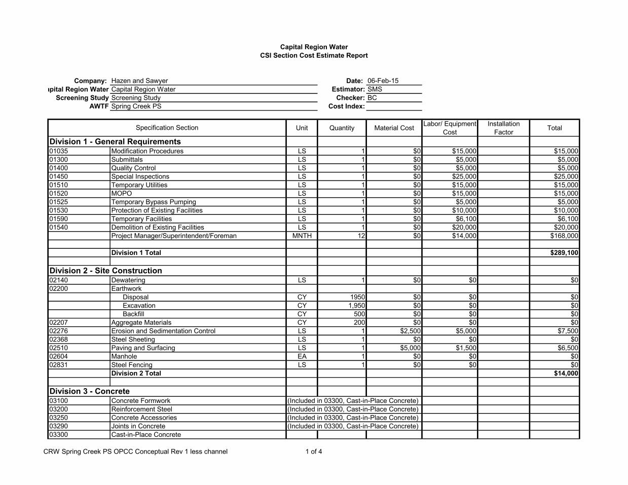
Company: Hazen and Sawyer Date: 06-Feb-15Capital Region Water Estimator: SMS
Screening Study Screening Study Checker: BCAWTF Spring Creek PS Cost Index:
Unit Quantity Material Cost Labor/ Equipment Cost
Installation Factor Total
Division 1 - General Requirements01035 Modification Procedures LS 1 $0 $15,000 $15,00001300 Submittals LS 1 $0 $5,000 $5,00001400 Quality Control LS 1 $0 $5,000 $5,00001450 Special Inspections LS 1 $0 $25,000 $25,00001510 Temporary Utilities LS 1 $0 $15,000 $15,00001520 MOPO LS 1 $0 $15,000 $15,00001525 Temporary Bypass Pumping LS 1 $0 $5,000 $5,00001530 Protection of Existing Facilities LS 1 $0 $10,000 $10,00001590 Temporary Facilities LS 1 $0 $6,100 $6,10001540 Demolition of Existing Facilities LS 1 $0 $20,000 $20,000
Project Manager/Superintendent/Foreman MNTH 12 $0 $14,000 $168,000
Division 1 Total $289,100
Division 2 - Site Construction02140 Dewatering LS 1 $0 $0 $002200 Earthwork
Disposal CY 1950 $0 $0 $0Excavation CY 1,950 $0 $0 $0Backfill CY 500 $0 $0 $0
02207 Aggregate Materials CY 200 $0 $0 $002276 Erosion and Sedimentation Control LS 1 $2,500 $5,000 $7,50002368 Steel Sheeting LS 1 $0 $0 $002510 Paving and Surfacing LS 1 $5,000 $1,500 $6,50002604 Manhole EA 1 $0 $0 $002831 Steel Fencing LS 1 $0 $0 $0
Division 2 Total $14,000
Division 3 - Concrete03100 Concrete Formwork (Included in 03300, Cast-in-Place Concrete)03200 Reinforcement Steel (Included in 03300, Cast-in-Place Concrete)03250 Concrete Accessories (Included in 03300, Cast-in-Place Concrete)03290 Joints in Concrete (Included in 03300, Cast-in-Place Concrete)03300 Cast-in-Place Concrete
Capital Region WaterCSI Section Cost Estimate Report
Capital Region Water
Specification Section
CRW Spring Creek PS OPCC Conceptual Rev 1 less channel 1 of 4

Slabs CY 0 $230 $69 1.3 $0Outside Walls CY 0 $500 $150 1.3 $0Elevated Slabs CY 0 $700 $350 1.5 $0Channel LF 0 $450 $150 1.3 $0Equipment Pads LS 0 $8,000 $0
Existing Channel Modifications/Wall Opening LS 1 $15,000 $15,000Existing Influent Chamber core opening LS 0 $5,000 $0
03350 Concrete Finishes (Included in 03300, Cast-in-Place Concrete)03370 Concrete Curing (Included in 03300, Cast-in-Place Concrete)
Division 3 Total $15,000
Division 4 - Masonry04220 Concrete Unit Masonry (incl. mortar and accessories) SF 375 $40 $8 1.2 $18,000
Division 4 Total $18,000
Division 5 - Metals05531 Gratings, Access Hatches, and Access Doors
30 in x 30 in Access Hatches EA 0 $1,500 $450 1.3 $0Fabricated Grating SF 0 $15 $5 1.3 $0
Division 5 Total $0
Division 6 - Wood & Plastics06100 Rough Carpentry (Included in 03300, Cast-in-Place Concrete)
Division 6 Total $0
Division 7 - Thermal & Moisture Protection07120 Waterproofing
Waterproofing foundations and retaining walls (Included in 03300, Cast-in-Place Concrete)07411 Built-up Bituminous Roofing SF 450 $8 $4 1.5 $5,40007620 Flashing and Trim
Flashing and Trim LS 1 $2,500 $1,250 1.5 $3,75007900 Joint Sealants
Calking, Sealant and Misc. Items LS 1 $1,000 $500 1.5 $1,500
Division 7 Total $10,650
Division 8 - Doors & Windows08115 Hollow Metal Doors and Frames
Hollow Metal Doors (Single) w/ hardware & glass EA 2 $1,500 $300 1.2 $3,600Hollow Metal Doors (Double) w/ hardware & glass EA 0 $3,000 $600 1.2 $0
08330 Roll-up Doors EA 1 $5,000 $1,000 1.2 $6,000
CRW Spring Creek PS OPCC Conceptual Rev 1 less channel 2 of 4

Division 8 Total $9,600.00
Division 9 - Finishes09801 MIC Coating System LS 1 $2,500 $1,250 1.5 $3,75009900 Painting LS 1 $1,500 $750 1.5 $2,250
Division 9 Total $6,000
Division 10 - Specialties (NOT USED)
Division 11 - Equipment11000 Equipment General Provisions (Included in Individual Sections)11420 Mechanical Screens and Screenings Compactors
Multi-rake Bar Screens EA 1 $280,000 $84,000 1.3 $364,000Screenings Compactors EA 1 $65,000 $19,500 1.3 $84,500
Manual Bar Screen EA 1 $15,000 $4,500 1.3 $19,500Division 11 Total $468,000
Division 12 - Furnishings (NOT USED)
Division 13 - Special Construction (NOT USED)
Division 14 - Conveying Systems (NOT USED)14405 Compacted Screenings Belt Conveyors EA 1 $60,000 $12,000 1.2 $72,00014600 Cranes and Hoists
Bridge Crane EA 1 $15,000 $3,000 1.2 $18,000Trolley Hoist EA 1 $5,000 $1,000 1.2 $6,000
Division 14 Total $96,000
Division 15 - Mechanical15000 Basic Mechanical Requirements (Included in Individual Sections)15006 Ductile Iron Pipe LF 0 $350 $70 1.2 $015030 Piping and Equipment Identification Systems LS 1 $1,500 $300 1.2 $1,80015200 Gate Operators (Included in 15204, Slide Gates)15204 Gates
60" X 48" w/Electric Open/Close Actuator EA 0 $21,000 $4,200 1.2 $0Stop Gates EA 0 $1,000 $200 1.2 $0
15390 Schedules (Included elsewhere in Div 15)Division 15 Total $1,800
Division 15 - HVAC (10%) $92,815
Division 16 - Electrical
Division 16 Total $1,266,000
CRW Spring Creek PS OPCC Conceptual Rev 1 less channel 3 of 4

Division 17 - Instrumentation and Control
Division 17 Total (5%) $46,408
Division 1 - 17 SubTotal $2,333,373
CRW Spring Creek PS OPCC Conceptual Rev 1 less channel 4 of 4

Hazen and Sawyer, P.C.
330 Innovation Blvd
Suite 104
State College, PA 16803
(814) 272-3332
(814) 272-3013 Fax
Appendix I

Duperon Corporation | 1200 Leon Scott Court | Saginaw, MI 48601 | P 989.754.8800 | F 989.754.2175 | TF 800.383.8479 | www.duperon.com
DATE: November 11, 2014 Mechanically Cleaned Bar Screen
Budgetary Proposal Number P6308 AWTF Headworks, PA
To: Scott Ambrust Hazen and Sawyer, P.E.
Sales Rep: Chad Fenstemaker President & General Sales Manager Kappe Associates, Inc 412-373-9303 412-373-9343 4268 Northern Pike Monroeville, PA 15146-2733 USA [email protected]
From: Mike Olvera Estimator Duperon Corporation Phone: (800) 383-8479 [email protected]
Lorene Bruns Regional Sales Manager Duperon Corporation Cell Phone: (989) 239-6856 [email protected]
Picture may not reflect this specific project

Budgetary Proposal
Number P6308 AWTF Headworks, PA
Duperon Corporation | 1200 Leon Scott Court | Saginaw, MI 48601 | P 989.754.8800 | F 989.754.2175 | TF 800.383.8479 | www.duperon.com
Scope of Supply: Based on site DWG and email received assumptions made for missing information.
2 each Mechanical Bar Screen - Link Driven, Front Cleaning, Front Return FlexRake® M Model Screens
o FPFS , Full Penetration, Fine Screen SSTL304 side fabrications, dead plate and cross members SSTL304 enclosure covering operating deck to discharge including SSTL access panels SSTL304 FlexLinks SSTL304 Flexors STD Drive Head:
o Drive Sprockets and end castings shall be SSTL o Drive Shaft shall be SSTL
Design criteria UHMW/SSTL scraper 1.00 ft of head differential structural design 0.25 inch x 0.75 inch x 0.13 inch SSTL316 tear shaped bar screen 4 ft discharge height into debris bin provided by others 00.00 degree from vertical .25 inch clear opening assumed none provided (see attached flow chart) 16.00 ft nominal length of FlexLink and scraper system 8.00 ft from channel invert to top of operating deck 8.00 ft channel height 5.00 ft channel width (each screen) 6,500 lbs estimated weight each
Hydraulic performance model 80.00 MGD per screen Peak Flow (see attached flow chart) 80.00 MGD per screen Peak Flow 37.7 MGD Average Daily Design Flow 21.6 MGD Average Daily Flow
Clarifications/Exceptions/By Others
The bar screen will be shipped fully assembled, if modular construction is needed because of site constraints, please see our Modular Construction notes below
Bar screens will need a minimum of 1.00 ft of water level to prevent galling of the moving SSTL parts. Modifications that may be needed in the channel, for example, a downstream weir are not included in this proposal
Field assembly of SSTL screen enclosure required Spreader bar may be required for unloading Crane may be required for unloading Anchor Bolts, per bar screen
Bolts for anchor toes and plates o (8) 1/2 inch dia x 4-1/2 inch Embed HAS Rods w/ Hilti RE-500 SD Adhesive
Bolts for Return Guide / Closeout o (14) 3/8 inch dia x 3-3/8 inch Embed HAS Rods w/ Hilti RE-500 SD Adhesive

Budgetary Proposal
Number P6308 AWTF Headworks, PA
Duperon Corporation | 1200 Leon Scott Court | Saginaw, MI 48601 | P 989.754.8800 | F 989.754.2175 | TF 800.383.8479 | www.duperon.com
1 each Hydraulic System: (Assumed Package Based on flooding at the site)
1-10 Gallon Submerged Style Reservoir with Sight Gauge and Filler Breather 1-3HP, 1800 RPM Balbor Explosion Proof Electric Motor 1-2 GPM Gear pump producing 2000 PSI 1-Ltt Neodyne Explosion Proof Adjustable Temperature Switch 1-Ltt Neodyne Explosion Proof Adjustable Pressure Switch 1-Gems Explosion Proof Level Switch 1-Vickers D03 Size Explosion Proof Directional Control Valve 24 Volt 1-Vickers Pressure Reducing Module 2-Pressure Gauges, 1 for system pressure, 1 for Reduced pressure 1-Vickers Return line Filter with Visual and Electrical Dirt Indication 1-System Relief Valve
Clarifications/Exceptions/By Others Plumbing to the hydraulic unit to be provided by others
Controls Clarifications/Exceptions/By Others The price below includes our standard controls set as indicated above. See our Controls Selection Guide to customize controls. All conduit and field wiring between the equipment Mounting hardware
FlexRake Spare Parts
(1) Drive Clevis Pin (10) Snap Rings (4) Link Clevis Pins (4) Hex Head Cap Screw (4) Scraper Nut (1) Never Seez (1) Snap Ring Tool (1) 14 oz. Tube Shur Stick
On Site Technical Assistance, Services After Start-up
(1) Trip(s) (1) Technician (2) 8 hour man-days If additional Technical Service days are required, please add per the rates included in the
Clarifications section of this scope of supply. Operation and Maintenance Manuals
(6) Hard Copies
Warranty One Year Standard material and workmanship Five year on rotating parts (screen only)
Freight to Jobsite
Price: $306,000

Budgetary Proposal
Number P6308 AWTF Headworks, PA
Duperon Corporation | 1200 Leon Scott Court | Saginaw, MI 48601 | P 989.754.8800 | F 989.754.2175 | TF 800.383.8479 | www.duperon.com
Optional Equipment: Quoted with Standard Electric Motor
(1) Duperon® Washer Compactor - Dual Auger System including basic controls Model WC2.C3.5
o 5HP Motor and gearbox o 3.15 ft from operating deck to top of washer compactor hipper rim o 5.56 ft long hopper length o 1.45 ft wide hopper width o SSTL304
Discharge chute design Standard chute
Water supply and drain criteria Non-Clog Flood Washing Utilizes filtered effluent or municipal water Consumes 3 to 5 gallons per minute at 40 to 60 PSI 3.00 inch NPT male drain connection 0.50 inch NPT water supply connection
Clarifications/Exceptions/By Others Some minor field assembly required Water supply and discharge piping Mounting hardware
Washer Compactor Spare Parts (1) Upper/Lower Support: Auger (1) Side Support: Auger (12) FHCS: 0.25-20x1 (12) 0.25 Flat Washer SAE (12) 0.25 Nylock Nut (1) AntiSeize Lubricant (1) Never Seez: 1oz Tube
Price: $ 80,000
Bar Screen Deadplate Heat Pad: 24 inch x 24 inch heat pad Thermostat Power by others
Price: $ 3,000
Washer Compactor - Heat Trace and Blanket Kit:
Required in applications where freezing temperatures are possible. Teflon heat blanket (weather proof) construction. Thermostat is NEMA 4X and has a remote probe for detecting temperature inside heat blanket.
Junction box includes materials necessary for explosion proof termination of heat trace. Power requirement is 120VAC / 600 watts. Power by others.
Components are suitable for CLASS I, DIVISION I areas.
Price: $ 5,000

Budgetary Proposal
Number P6308 AWTF Headworks, PA
Duperon Corporation | 1200 Leon Scott Court | Saginaw, MI 48601 | P 989.754.8800 | F 989.754.2175 | TF 800.383.8479 | www.duperon.com
Modular Construction Notes:
The bar screen will be shipped from the factory fully assembled with the exception of the operating deck enclosure(s) and intermediate deck side shields, if there are any specified.
If this installation requires modular construction, please be guided by the following: The installation contractor will need to disassemble the bar screen at the site and in locations
directed by Duperon and approved for during the submittal process. The contractor will then reassemble the bar screen in the facility. The contactor is required to provide all material, equipment and labor for this process.
The overall bar screen unit will be fabricated so that it can be split into disassembled segments at the project site. Precise segments depend on site constraints and bar screen dimensions. Each segment will have the exploded sidefab detail as illustrated in our installation guide. The weights of the sections will be proportioned from the overall weight listed in the proposal.
The drive head assembly may need to be removed if site constraints, for example navigating around a corner, require it.
The FlexLink and scraper system will need to be removed in segments of approximately six links, or about 6 ft each. The FlexLinks have a snap ring holding the FlexLink pin. These FlexLinks will need to be marked so that the contractor knows what FlexLink connects to what FlexLink during the reassembly process.
The enclosures and or side shields for the operating deck and intermediated deck, if required will be shipped unassembled. These will comprise anywhere from 10 to 20 pieces per bar screen. These pieces of SSTL sheet metal will need to be bolted together once the bar screen is installed.
Duperon contact: If any have further questions on our modular construction process, please contact our application engineer, Jan LaFave at 800.383.8479
Disclaimer: Duperon cautions the contractor, whom we assume is familiar with bar screens that an allowance for the disassembly should be accounted for in their bid. Without knowing the skill set, rigging provisions, and manpower the selected contractor will apply, it is difficult for us to provide specific details on this subject. The above language is only made as an approximation and is not guaranteed.
Clarifications:
Prices are valid for 30 days Submittals: 4-6 weeks after approved purchase order Equipment Delivery: 8-12 weeks after approval (depending on work load) Scope of supply and pricing above does not include additional structure for seismic, additional
head differential or high wind conditions See Duperon Contractor Installation Guides for guidance in estimating these costs. Duperon requires 2 week’s advanced notice in writing to schedule field service technician on
site. Field Services will be provided as outlined in this proposal. Duperon field service rate is $750
per day plus travel and per diem expenses. If field service personnel arrive on site as scheduled and the project is not ready for intended services to be performed, Duperon will invoice for additional days, if required. If the time required is greater than the time listed in this proposal, Duperon will invoice at the above rates.
The specifications listed are the only specifications which shall apply to this proposal either directly or by reference. Any additional specifications, with equipment or requirements specified therein, that are not specifically included as part of this offer are excluded from this proposal.

Budgetary Proposal
Number P6308 AWTF Headworks, PA
Duperon Corporation | 1200 Leon Scott Court | Saginaw, MI 48601 | P 989.754.8800 | F 989.754.2175 | TF 800.383.8479 | www.duperon.com
Not Included:
Anything not specifically stated in this Proposal. Bonding, tariffs, permits, taxes, liquidated damages. Construction and /or installation work of any kind at the jobsite. On-site conditions affecting the work described or which affects the installation. Conduit, stands, control mounting wiring, junction boxes, or other accessories. Any site work or installation tasks (ie, unloading, placement, dewatering, diving, clearing the
forebay, wiring, provision of concrete structure, etc.), equipment (such as cranes, hammer drills, etc.), or anchor bolts.
Pre-installation tasks such as touch-up painting, checking bolts for tightness, removal of shipping containment devices, etc.
Engineering: Does not include drawings other than those for the FlexRake. Additional structure for seismic or high wind conditions. Offloading or handling of delivered equipment. Union labor for all field support services. Controls not specifically listed above. Videotaping of the training sessions Release of proprietary information. Insulation or weather proofing. Site/field painting or touch up. Vibration and noise testing. Anchor Bolts by others. Discharge system. Stilling wells.
Proposal Terms:
This offer is subject to the enclosed Duperon Corporation Terms and Conditions page unless
alternate terms and conditions are specifically negotiated in writing and are signed/accepted by Duperon Corporation at the time of purchase.
May be subject to material price escalation. This proposal is based upon the information available at this time and may be impacted by
future specifications, scope, and other requirements. Duperon Corporation retains the right to revise, withdraw, or negotiate this offer at any time
prior to signing a material contract.
Right to Refuse:
This proposal is based upon the information available at this time and may be impacted by future specifications, scope, and other requirements. This information may be relied upon and used for project estimating purposes only. Note In the event of cancellation of a purchase order or contract, Duperon Corporation will be compensated for all costs that it or its subcontractors have incurred for performance of work in good faith. Due to the current volatility of the steel market, prices may be impacted at time of order. Please be advised that Duperon Corporation retains the right to revise, withdraw, or negotiate this offer at any time prior to signing a material contract.

Date: November 11, 2014 Project: AWTF Headworks, PA
Number: P6308
(*) Assumed 1200 Leon Scott Court | Saginaw, MI 48601 | P 989.754.8800 | F 989.754.2175 | TF 800.383.8479 | www.duperon.com
©Copyright 2014, Duperon Corporation. All Rights Reserved.
HYDRAULIC CALCULATIONS
Notes: 80 MGD max water 7 ft 1 ft freebaord. Slot Velocity HIGH

Date: November 11, 2014 Project: AWTF Headworks, PA
Number: P6308
(*) Assumed 1200 Leon Scott Court | Saginaw, MI 48601 | P 989.754.8800 | F 989.754.2175 | TF 800.383.8479 | www.duperon.com
©Copyright 2014, Duperon Corporation. All Rights Reserved.
HYDRAULIC CALCULATIONS
Notes: 37.7 MGD Slot Velocity HIGH

Date: November 11, 2014 Project: AWTF Headworks, PA
Number: P6308
(*) Assumed 1200 Leon Scott Court | Saginaw, MI 48601 | P 989.754.8800 | F 989.754.2175 | TF 800.383.8479 | www.duperon.com
©Copyright 2014, Duperon Corporation. All Rights Reserved.
HYDRAULIC CALCULATIONS
Notes: 21.6 MGD

Controlled Flexibility and Positive Engagement with the Lifelong Security of Adaptive Technology
FlexRake® FPFS-MMechanically Cleaned Bar Screens
• No Lower Sprockets, Bearings or Tracks to Foul or Jam
• Millennial Platform, Adaptive for Life
• Controlled Flexibility and Positive Engagement
• Five-Year Warranty for Wastewater Applications
• Ideal for Vertical and Near-Vertical Applications
Simple front cleaning, front return Duperon® FlexRake® technology. Utilizes stainless steel tear-shaped bars with 1/4 inch, 3/8 inch or 1/2 inch openings.
LIFE LONG ADAPTABILITYFINE SCREENING

1200 Leon Scott Court | Saginaw, MI 48601 | P 989.754.8800 | F 989.754.2175 | TF 800.383.8479 | www.duperon.comPatent Pending. Duperon® and FlexRake® are registered trademarks of Duperon Corporation. FlexLink™, Jam-Evasion™, Thru-Bar™ are trademarks of Duperon Corporation. Your Path to the FutureSM is a service mark of Duperon Corporation. © Copyright 2013, Duperon Corporation.
2229/12/13/1M
The Duperon® FlexRake® FPFS-M
Fixed Stainless Steel Drive Head
Modular Design for Life-Long Adaptability
Smaller Footprint
Jam Evasion™ Technology
Lifts or Pivots Around Debris
Thru-Bar™ Technology
Cleans 3 Sides of Bar
No Maintenance
Bearing
Enclosure Module
Screen Module
Screen Module
Enclosure Module
Raking Module
Raking Module
Reduced Profile
Rear Enclosure(not shown)
Double Wiping Debris Blade
Chute
Bar Screen Module
TYPICAL APPLICATIONSIdeal for vertical and near-vertical applications in wastewater, retrofit situations with channel constraints, or where future screening options may be required.
UNIT WIDTH2 feet to 12 feet
UNIT LENGTH10 feet to 100 feet
ANGLE OF INSTALLATIONVertical to 45 degrees
STANDARD MATERIALS OF CONSTRUCTION
Standard: 304 Stainless SteelAvailable in: 316 Stainless Steel
BAR OPENING1/4 inch, 3/8 inch and 1/2 inch
STANDARD SCRAPER SPACINGEvery 2nd link, 21 inches
SCRAPER CONFIGURATIONThru-Bar™, all SSTL construction
TYPICAL MOTOR1/2 HP, 1 PH/3 PH explosion-proof, inverter duty motor
STANDARD OPERATING SPEED0.5 RPM Can be increased to 2.2 RPM in high flow conditions. 1 discharge/minute on low; 4 discharges/minute on high. Scrapers move 28 inches/minute.
SHIPPING DATA Ships fully assembled. Can be provided in modular form to support installation.
STANDARD CONTROLS OPTIONSPackages range from simple start/stop to sophisticated automation. Motor overload protection provided. Contact Duperon® for further details and assistance in selecting the perfect package for your site.
OPERATION OPTIONSContinuous/Manual.Automatic with timer, float, SCADA, differential/high level sensing options with I/O as needed.
Lower Profile Over Deck
Smaller Footprint
Cleans within one inch of
Channel Floor

Duperon Corporation | 1200 Leon Scott Court | Saginaw, MI 48601 | P 989.754.8800 | F 989.754.2175 | TF 800.383.8479 | www.duperon.com
DATE: November 11, 2014 Mechanically Cleaned Bar Screen
Budgetary Proposal Number P6261 Front Street Pump Station, PA
To: Scott Ambrust Hazen and Sawyer, P.E.
Sales Rep: Chad Fenstemaker President & General Sales Manager Kappe Associates, Inc 412-373-9303 412-373-9343 4268 Northern Pike Monroeville, PA 15146-2733 USA [email protected]
From: Mike Olvera Estimator Duperon Corporation Phone: (800) 383-8479 [email protected]
Lorene Bruns Regional Sales Manager Duperon Corporation Cell Phone: (989) 239-6856 [email protected]
Picture may not reflect this specific project

Budgetary Proposal
Number P6261 Front Street Pump Station, PA
Duperon Corporation | 1200 Leon Scott Court | Saginaw, MI 48601 | P 989.754.8800 | F 989.754.2175 | TF 800.383.8479 | www.duperon.com
Scope of Supply: Based on site DWG and email received assumptions made for missing information.
2 each Mechanical Bar Screen - Link Driven, Front Cleaning, Front Return FlexRake® M Model Screens
o FP , Full Penetration Screen SSTL304 side fabrications, dead plate and cross members SSTL304 enclosure covering operating deck to discharge including SSTL access panels SSTL304 FlexLinks SSTL304 Flexors STD Drive Head:
o Drive Sprockets and end castings shall be SSTL o Drive Shaft shall be SSTL
Design criteria UHMW scraper 1.00 ft of head differential structural design 0.25 inch x 1.00 inch true bar 4 ft discharge height into debris bin provided by others 15.00 degree from vertical 1.50 inch clear opening assumed none provided (see attached flow chart) 30.00 ft nominal length of FlexLink and scraper system 20.50 ft from channel invert to top of operating deck 20.50 ft channel height 5.00 ft channel width (each screen) 7,500 lbs estimated weight each
Hydraulic performance model 80.00 MGD per screen Peak Flow (see attached flow chart) 80.00 MGD per screen Peak Flow 37.7 MGD Average Daily Design Flow 21.6 MGD Average Daily Flow
Clarifications/Exceptions/By Others
The bar screen will be shipped fully assembled, if modular construction is needed because of site constraints, please see our Modular Construction notes below
Bar screens will need a minimum of 1.00 ft of water level to prevent galling of the moving SSTL parts. Modifications that may be needed in the channel, for example, a downstream weir are not included in this proposal
Field assembly of SSTL screen enclosure required Spreader bar may be required for unloading Crane may be required for unloading Anchor Bolts, per bar screen
Bolts for anchor toes and plates o (8) 1/2 inch dia x 4-1/2 inch Embed HAS Rods w/ Hilti RE-500 SD Adhesive
Bolts for Return Guide / Closeout o (14) 3/8 inch dia x 3-3/8 inch Embed HAS Rods w/ Hilti RE-500 SD Adhesive

Budgetary Proposal
Number P6261 Front Street Pump Station, PA
Duperon Corporation | 1200 Leon Scott Court | Saginaw, MI 48601 | P 989.754.8800 | F 989.754.2175 | TF 800.383.8479 | www.duperon.com
1 each Controls Package, Main Panel (assumed control package)
(1) Wall mount NEMA 4X SSTL Enclosure o (2) mechanical bar screen
(2) AC Tech VFD drive for speed control, 1/2 HP Terminal blocks, ETM’s, breakers, timers and relays where required Pilot lights, push buttons and selector switches on front door Relay logic controls with floats
Local to equipment mounted devices (2) Three hole NEMA 7/9 PB enclosure for E-Stop, Forward and Reverse
Instrumentation NA
Controls Clarifications/Exceptions/By Others The price below includes our standard controls set as indicated above. See our Controls Selection Guide to customize controls. All conduit and field wiring between the equipment Mounting hardware
FlexRake Spare Parts
(1) Drive Clevis Pin (10) Snap Rings (4) Link Clevis Pins (4) Hex Head Cap Screw (4) Scraper Nut (1) Never Seez (1) Snap Ring Tool (1) 14 oz. Tube Shur Stick
On Site Technical Assistance, Services After Start-up
(1) Trip(s) (1) Technician (2) 8 hour man-days If additional Technical Service days are required, please add per the rates included in the
Clarifications section of this scope of supply. Operation and Maintenance Manuals
(6) Hard Copies
Warranty One Year Standard material and workmanship Five year on rotating parts (screen only)
Freight to Jobsite
Price: $344,000

Budgetary Proposal
Number P6261 Front Street Pump Station, PA
Duperon Corporation | 1200 Leon Scott Court | Saginaw, MI 48601 | P 989.754.8800 | F 989.754.2175 | TF 800.383.8479 | www.duperon.com
Optional Equipment: Quoted with Standard Electric Motor
(1) Duperon® Washer Compactor - Dual Auger System including basic controls Model WC2.C3.5
o 5HP Motor and gearbox o 3.15 ft from operating deck to top of washer compactor hipper rim o 5.56 ft long hopper length o 1.45 ft wide hopper width o SSTL304
Discharge chute design Standard chute
Water supply and drain criteria Non-Clog Flood Washing Utilizes filtered effluent or municipal water Consumes 3 to 5 gallons per minute at 40 to 60 PSI 3.00 inch NPT male drain connection 0.50 inch NPT water supply connection
Clarifications/Exceptions/By Others Some minor field assembly required Water supply and discharge piping Mounting hardware
Washer Compactor Spare Parts (1) Upper/Lower Support: Auger (1) Side Support: Auger (12) FHCS: 0.25-20x1 (12) 0.25 Flat Washer SAE (12) 0.25 Nylock Nut (1) AntiSeize Lubricant (1) Never Seez: 1oz Tube
Price: $ 80,000
Bar Screen Deadplate Heat Pad: 24 inch x 24 inch heat pad Thermostat Power by others
Price: $ 3,000
Washer Compactor - Heat Trace and Blanket Kit:
Required in applications where freezing temperatures are possible. Teflon heat blanket (weather proof) construction. Thermostat is NEMA 4X and has a remote probe for detecting temperature inside heat blanket.
Junction box includes materials necessary for explosion proof termination of heat trace. Power requirement is 120VAC / 600 watts. Power by others.
Components are suitable for CLASS I, DIVISION I areas.
Price: $ 5,000

Budgetary Proposal
Number P6261 Front Street Pump Station, PA
Duperon Corporation | 1200 Leon Scott Court | Saginaw, MI 48601 | P 989.754.8800 | F 989.754.2175 | TF 800.383.8479 | www.duperon.com
Modular Construction Notes:
The bar screen will be shipped from the factory fully assembled with the exception of the operating deck enclosure(s) and intermediate deck side shields, if there are any specified.
If this installation requires modular construction, please be guided by the following: The installation contractor will need to disassemble the bar screen at the site and in locations
directed by Duperon and approved for during the submittal process. The contractor will then reassemble the bar screen in the facility. The contactor is required to provide all material, equipment and labor for this process.
The overall bar screen unit will be fabricated so that it can be split into disassembled segments at the project site. Precise segments depend on site constraints and bar screen dimensions. Each segment will have the exploded sidefab detail as illustrated in our installation guide. The weights of the sections will be proportioned from the overall weight listed in the proposal.
The drive head assembly may need to be removed if site constraints, for example navigating around a corner, require it.
The FlexLink and scraper system will need to be removed in segments of approximately six links, or about 6 ft each. The FlexLinks have a snap ring holding the FlexLink pin. These FlexLinks will need to be marked so that the contractor knows what FlexLink connects to what FlexLink during the reassembly process.
The enclosures and or side shields for the operating deck and intermediated deck, if required will be shipped unassembled. These will comprise anywhere from 10 to 20 pieces per bar screen. These pieces of SSTL sheet metal will need to be bolted together once the bar screen is installed.
Duperon contact: If any have further questions on our modular construction process, please contact our application engineer, Jan LaFave at 800.383.8479
Disclaimer: Duperon cautions the contractor, whom we assume is familiar with bar screens that an allowance for the disassembly should be accounted for in their bid. Without knowing the skill set, rigging provisions, and manpower the selected contractor will apply, it is difficult for us to provide specific details on this subject. The above language is only made as an approximation and is not guaranteed.
Clarifications:
Prices are valid for 30 days Submittals: 4-6 weeks after approved purchase order Equipment Delivery: 8-12 weeks after approval (depending on work load) Scope of supply and pricing above does not include additional structure for seismic, additional
head differential or high wind conditions See Duperon Contractor Installation Guides for guidance in estimating these costs. Duperon requires 2 week’s advanced notice in writing to schedule field service technician on
site. Field Services will be provided as outlined in this proposal. Duperon field service rate is $750
per day plus travel and per diem expenses. If field service personnel arrive on site as scheduled and the project is not ready for intended services to be performed, Duperon will invoice for additional days, if required. If the time required is greater than the time listed in this proposal, Duperon will invoice at the above rates.
The specifications listed are the only specifications which shall apply to this proposal either directly or by reference. Any additional specifications, with equipment or requirements specified therein, that are not specifically included as part of this offer are excluded from this proposal.

Budgetary Proposal
Number P6261 Front Street Pump Station, PA
Duperon Corporation | 1200 Leon Scott Court | Saginaw, MI 48601 | P 989.754.8800 | F 989.754.2175 | TF 800.383.8479 | www.duperon.com
Not Included:
Anything not specifically stated in this Proposal. Bonding, tariffs, permits, taxes, liquidated damages. Construction and /or installation work of any kind at the jobsite. On-site conditions affecting the work described or which affects the installation. Conduit, stands, control mounting wiring, junction boxes, or other accessories. Any site work or installation tasks (ie, unloading, placement, dewatering, diving, clearing the
forebay, wiring, provision of concrete structure, etc.), equipment (such as cranes, hammer drills, etc.), or anchor bolts.
Pre-installation tasks such as touch-up painting, checking bolts for tightness, removal of shipping containment devices, etc.
Engineering: Does not include drawings other than those for the FlexRake. Additional structure for seismic or high wind conditions. Offloading or handling of delivered equipment. Union labor for all field support services. Controls not specifically listed above. Videotaping of the training sessions Release of proprietary information. Insulation or weather proofing. Site/field painting or touch up. Vibration and noise testing. Anchor Bolts by others. Discharge system. Stilling wells.
Proposal Terms:
This offer is subject to the enclosed Duperon Corporation Terms and Conditions page unless
alternate terms and conditions are specifically negotiated in writing and are signed/accepted by Duperon Corporation at the time of purchase.
May be subject to material price escalation. This proposal is based upon the information available at this time and may be impacted by
future specifications, scope, and other requirements. Duperon Corporation retains the right to revise, withdraw, or negotiate this offer at any time
prior to signing a material contract.
Right to Refuse:
This proposal is based upon the information available at this time and may be impacted by future specifications, scope, and other requirements. This information may be relied upon and used for project estimating purposes only. Note In the event of cancellation of a purchase order or contract, Duperon Corporation will be compensated for all costs that it or its subcontractors have incurred for performance of work in good faith. Due to the current volatility of the steel market, prices may be impacted at time of order. Please be advised that Duperon Corporation retains the right to revise, withdraw, or negotiate this offer at any time prior to signing a material contract.

Date: November 11, 2014 Project: Front Street Pump Station PA
Number: P6261
(*) Assumed 1200 Leon Scott Court | Saginaw, MI 48601 | P 989.754.8800 | F 989.754.2175 | TF 800.383.8479 | www.duperon.com
©Copyright 2014, Duperon Corporation. All Rights Reserved.
HYDRAULIC CALCULATIONS
Notes:

LOWEST COST OF OWNERSHIPCOARSE SCREENING
Controlled Flexibility and Thru-Bar™ Cleaning, with the Lifelong Security of Adaptive Technology
• NoLowerSprockets,BearingsorTrackstoFoulorJam
• MillennialPlatform,AdaptiveforLife
• ControlledFlexibilityandPositiveEngagement
• Five-YearWarrantyforWastewaterApplications
• IdealforVerticalandNear-VerticalApplications
FlexRake® FP-MMechanicallyCleanedBarScreensSimplefrontcleaning,frontreturnDuperon®FlexRake®technology.Stainlesssteel,rectangulartruebarconstructionwithopeningsof5/8inchto4inches.

1200LeonScottCourt|Saginaw,MI48601|P989.754.8800|F989.754.2175|TF800.383.8479|www.duperon.comPatentPending.Duperon®andFlexRake®areregisteredtrademarksofDuperonCorporation.FlexLink™,Jam-Evasion™,Thru-Bar™aretrademarksofDuperonCorporation.YourPathtotheFutureSMisaservicemarkofDuperonCorporation.©Copyright2013,DuperonCorporation.
2230/12/13/1M
TYPICAL APPLICATIONSIdealforverticalornear-verticalapplicationsinwastewater,retrofitsituationswithchannelconstraints,orwherefuturescreeningoptionsmayberequired.
UNIT WIDTH2feetto12feet
UNIT LENGTH10feetto100feet
ANGLE OF INSTALLATIONVerticalto45degrees
STANDARD MATERIALS OF CONSTRUCTION
Standard:304StainlessSteelAlternative:316StainlessSteel
BAR OPENING0.63inchesto4inches
STANDARD SCRAPER SPACINGEvery2ndlink
SCRAPER CONFIGURATIONUHMW-PEThru-Bar™scrapers
TYPICAL MOTOR1/2HP,inverterduty,explosionproof
STANDARD OPERATING SPEED0.5RPMCanbeincreasedto2.2RPMinhighflowconditions1discharge/minuteScrapersmove28inches/minute
SHIPPING DATAShipsfullyassembled.Canbeprovidedinmodularformtosupportinstallation.
STANDARD CONTROLS OPTIONSPackagesrangefromsimplestart/stoptosophisticatedautomation,includingmotoroverloadprotection.ContactDuperon®forfurtherdetailsandassistanceinselectingtheperfectpackageforyoursite.
OPERATION OPTIONSContinuous/Manual.Automaticwithtimer,float,SCADA,differential/highlevelsensingoptionswithI/Oasneeded.
The Duperon® FlexRake® FP-M
FixedStainlessSteelDriveHead
ModularDesignforLifelongAdaptability
SmallerFootprint
JamEvasion™Technology
LiftsorPivotsAroundDebris
Cleanswithinoneinchof
ChannelFloor
Thru-Bar™Technology
Cleans3SidesofBar
NoMaintenance
Bearing
EnclosureModule
ScreenModule
ScreenModule
EnclosureModule
RakingModule
RakingModule
ReducedProfile
RearEnclosure(notshown)
DoubleWipingDebrisBlade
Chute
BarScreenModule
LowerProfileOverDeck
SmallerFootprint

Date: March 13, 2015 Project: Front Street Pump Station PA
Number: P6261
(*) Assumed 1200 Leon Scott Court | Saginaw, MI 48601 | P 989.754.8800 | F 989.754.2175 | TF 800.383.8479 | www.duperon.com
©Copyright 2014, Duperon Corporation. All Rights Reserved.
HYDRAULIC CALCULATIONS
Notes: 45 MGD

Date: March 13, 2015 Project: Front Street Pump Station PA
Number: P6261
(*) Assumed 1200 Leon Scott Court | Saginaw, MI 48601 | P 989.754.8800 | F 989.754.2175 | TF 800.383.8479 | www.duperon.com
©Copyright 2014, Duperon Corporation. All Rights Reserved.
HYDRAULIC CALCULATIONS
Notes: 60 MGD

Duperon Corporation | 1200 Leon Scott Court | Saginaw, MI 48601 | P 989.754.8800 | F 989.754.2175 | TF 800.383.8479 | www.duperon.com
DATE: November 11, 2014 Mechanically Cleaned Bar Screen
Budgetary Proposal Number P7550 Spring Creek Pump Station - East Interceptor
To: Scott Ambrust Hazen and Sawyer, P.E.
Sales Rep: Chad Fenstemaker President & General Sales Manager Kappe Associates, Inc 412-373-9303 412-373-9343 4268 Northern Pike Monroeville, PA 15146-2733 USA [email protected]
From: Mike Olvera Estimator Duperon Corporation Phone: (800) 383-8479 [email protected]
Lorene Bruns Regional Sales Manager Duperon Corporation Cell Phone: (989) 239-6856 [email protected]
Picture may not reflect this specific project

Budgetary Proposal
Number P7550 Spring Creek Pump Station - East Interceptor
Duperon Corporation | 1200 Leon Scott Court | Saginaw, MI 48601 | P 989.754.8800 | F 989.754.2175 | TF 800.383.8479 | www.duperon.com
Scope of Supply: Based on site DWG and email received assumptions made for missing information.
1 each Mechanical Bar Screen - Link Driven, Front Cleaning, Front Return FlexRake® M Model Screens
o FP , Full Penetration Screen SSTL304 side fabrications, dead plate and cross members SSTL304 enclosure covering operating deck to discharge including SSTL access panels SSTL304 FlexLinks SSTL304 Flexors STD Drive Head:
o Drive Sprockets and end castings shall be SSTL o Drive Shaft shall be SSTL
Design criteria UHMW scraper 1.00 ft of head differential structural design 0.25 inch x 0.75 inch x 0.13 inch SSTL316 tear shaped bar screen 4 ft discharge height into debris bin provided by others 00.00 degree from vertical .75 inch clear opening (see attached flow chart) 25.00 ft nominal length of FlexLink and scraper system 16.13 ft from channel invert to top of operating deck 16.13 ft channel height 3.00 ft channel width (each screen) 7,500 lbs estimated weight each
Hydraulic performance model 30.00 MGD design flow and 10 MGD Average Daily Design Flow flow (see attached flow chart)
Clarifications/Exceptions/By Others
The bar screen will be shipped fully assembled, if modular construction is needed because of site constraints, please see our Modular Construction notes below
Bar screens will need a minimum of 1.00 ft of water level to prevent galling of the moving SSTL parts. Modifications that may be needed in the channel, for example, a downstream weir are not included in this proposal
Field assembly of SSTL screen enclosure required Spreader bar may be required for unloading Crane may be required for unloading Anchor Bolts, per bar screen
Bolts for anchor toes and plates o (8) 1/2 inch dia x 4-1/2 inch Embed HAS Rods w/ Hilti RE-500 SD Adhesive
Bolts for Return Guide / Closeout o (14) 3/8 inch dia x 3-3/8 inch Embed HAS Rods w/ Hilti RE-500 SD Adhesive

Budgetary Proposal
Number P7550 Spring Creek Pump Station - East Interceptor
Duperon Corporation | 1200 Leon Scott Court | Saginaw, MI 48601 | P 989.754.8800 | F 989.754.2175 | TF 800.383.8479 | www.duperon.com
1 each Controls Package, Main Panel (assumed control package)
(1) Wall mount NEMA 4X SSTL Enclosure o (1) mechanical bar screen
(1) AC Tech VFD drive for speed control, 1/2 HP Terminal blocks, ETM’s, breakers, timers and relays where required Pilot lights, push buttons and selector switches on front door Relay logic controls with floats
Local to equipment mounted devices (1) Three hole NEMA 7/9 PB enclosure for E-Stop, Forward and Reverse
Instrumentation NA
Controls Clarifications/Exceptions/By Others The price below includes our standard controls set as indicated above. See our Controls Selection Guide to customize controls. All conduit and field wiring between the equipment Mounting hardware
FlexRake Spare Parts
(1) Drive Clevis Pin (10) Snap Rings (4) Link Clevis Pins (4) Hex Head Cap Screw (4) Scraper Nut (1) Never Seez (1) Snap Ring Tool (1) 14 oz. Tube Shur Stick
On Site Technical Assistance, Services After Start-up
(1) Trip(s) (1) Technician (2) 8 hour man-days If additional Technical Service days are required, please add per the rates included in the
Clarifications section of this scope of supply. Operation and Maintenance Manuals
(6) Hard Copies
Warranty One Year Standard material and workmanship Five year on rotating parts (screen only)
Freight to Jobsite
Price: $190,000

Budgetary Proposal
Number P7550 Spring Creek Pump Station - East Interceptor
Duperon Corporation | 1200 Leon Scott Court | Saginaw, MI 48601 | P 989.754.8800 | F 989.754.2175 | TF 800.383.8479 | www.duperon.com
Optional Equipment:
(1) Duperon® Washer Compactor - Dual Auger System including basic controls Model WC2.A2.5
o 3/4HP Motor and gearbox o 3.15 ft from operating deck to top of washer compactor hipper rim o 3.56 ft long hopper length o 1.45 ft wide hopper width o SSTL304
Discharge chute design Standard chute
Water supply and drain criteria Non-Clog Flood Washing Utilizes filtered effluent or municipal water Consumes 3 to 5 gallons per minute at 40 to 60 PSI 3.00 inch NPT male drain connection 0.50 inch NPT water supply connection
Clarifications/Exceptions/By Others Some minor field assembly required Water supply and discharge piping Mounting hardware
Washer Compactor Spare Parts (1) Upper/Lower Support: Auger (1) Side Support: Auger (12) FHCS: 0.25-20x1 (12) 0.25 Flat Washer SAE (12) 0.25 Nylock Nut (1) AntiSeize Lubricant (1) Never Seez: 1oz Tube
Price: $ 55,000
Bar Screen Deadplate Heat Pad: 24 inch x 24 inch heat pad Thermostat Power by others
Price: $ 3,000
Washer Compactor - Heat Trace and Blanket Kit:
Required in applications where freezing temperatures are possible. Teflon heat blanket (weather proof) construction. Thermostat is NEMA 4X and has a remote probe for detecting temperature inside heat blanket.
Junction box includes materials necessary for explosion proof termination of heat trace. Power requirement is 120VAC / 600 watts. Power by others.
Components are suitable for CLASS I, DIVISION I areas.
Price: $ 5,000

Budgetary Proposal
Number P7550 Spring Creek Pump Station - East Interceptor
Duperon Corporation | 1200 Leon Scott Court | Saginaw, MI 48601 | P 989.754.8800 | F 989.754.2175 | TF 800.383.8479 | www.duperon.com
Modular Construction Notes:
The bar screen will be shipped from the factory fully assembled with the exception of the operating deck enclosure(s) and intermediate deck side shields, if there are any specified.
If this installation requires modular construction, please be guided by the following: The installation contractor will need to disassemble the bar screen at the site and in locations
directed by Duperon and approved for during the submittal process. The contractor will then reassemble the bar screen in the facility. The contactor is required to provide all material, equipment and labor for this process.
The overall bar screen unit will be fabricated so that it can be split into disassembled segments at the project site. Precise segments depend on site constraints and bar screen dimensions. Each segment will have the exploded sidefab detail as illustrated in our installation guide. The weights of the sections will be proportioned from the overall weight listed in the proposal.
The drive head assembly may need to be removed if site constraints, for example navigating around a corner, require it.
The FlexLink and scraper system will need to be removed in segments of approximately six links, or about 6 ft each. The FlexLinks have a snap ring holding the FlexLink pin. These FlexLinks will need to be marked so that the contractor knows what FlexLink connects to what FlexLink during the reassembly process.
The enclosures and or side shields for the operating deck and intermediated deck, if required will be shipped unassembled. These will comprise anywhere from 10 to 20 pieces per bar screen. These pieces of SSTL sheet metal will need to be bolted together once the bar screen is installed.
Duperon contact: If any have further questions on our modular construction process, please contact our application engineer, Jan LaFave at 800.383.8479
Disclaimer: Duperon cautions the contractor, whom we assume is familiar with bar screens that an allowance for the disassembly should be accounted for in their bid. Without knowing the skill set, rigging provisions, and manpower the selected contractor will apply, it is difficult for us to provide specific details on this subject. The above language is only made as an approximation and is not guaranteed.
Clarifications:
Prices are valid for 30 days Submittals: 4-6 weeks after approved purchase order Equipment Delivery: 8-12 weeks after approval (depending on work load) Scope of supply and pricing above does not include additional structure for seismic, additional
head differential or high wind conditions See Duperon Contractor Installation Guides for guidance in estimating these costs. Duperon requires 2 week’s advanced notice in writing to schedule field service technician on
site. Field Services will be provided as outlined in this proposal. Duperon field service rate is $750
per day plus travel and per diem expenses. If field service personnel arrive on site as scheduled and the project is not ready for intended services to be performed, Duperon will invoice for additional days, if required. If the time required is greater than the time listed in this proposal, Duperon will invoice at the above rates.
The specifications listed are the only specifications which shall apply to this proposal either directly or by reference. Any additional specifications, with equipment or requirements specified therein, that are not specifically included as part of this offer are excluded from this proposal.

Budgetary Proposal
Number P7550 Spring Creek Pump Station - East Interceptor
Duperon Corporation | 1200 Leon Scott Court | Saginaw, MI 48601 | P 989.754.8800 | F 989.754.2175 | TF 800.383.8479 | www.duperon.com
Not Included:
Anything not specifically stated in this Proposal. Bonding, tariffs, permits, taxes, liquidated damages. Construction and /or installation work of any kind at the jobsite. On-site conditions affecting the work described or which affects the installation. Conduit, stands, control mounting wiring, junction boxes, or other accessories. Any site work or installation tasks (ie, unloading, placement, dewatering, diving, clearing the
forebay, wiring, provision of concrete structure, etc.), equipment (such as cranes, hammer drills, etc.), or anchor bolts.
Pre-installation tasks such as touch-up painting, checking bolts for tightness, removal of shipping containment devices, etc.
Engineering: Does not include drawings other than those for the FlexRake. Additional structure for seismic or high wind conditions. Offloading or handling of delivered equipment. Union labor for all field support services. Controls not specifically listed above. Videotaping of the training sessions Release of proprietary information. Insulation or weather proofing. Site/field painting or touch up. Vibration and noise testing. Anchor Bolts by others. Discharge system. Stilling wells.
Proposal Terms:
This offer is subject to the enclosed Duperon Corporation Terms and Conditions page unless
alternate terms and conditions are specifically negotiated in writing and are signed/accepted by Duperon Corporation at the time of purchase.
May be subject to material price escalation. This proposal is based upon the information available at this time and may be impacted by
future specifications, scope, and other requirements. Duperon Corporation retains the right to revise, withdraw, or negotiate this offer at any time
prior to signing a material contract.
Right to Refuse:
This proposal is based upon the information available at this time and may be impacted by future specifications, scope, and other requirements. This information may be relied upon and used for project estimating purposes only. Note In the event of cancellation of a purchase order or contract, Duperon Corporation will be compensated for all costs that it or its subcontractors have incurred for performance of work in good faith. Due to the current volatility of the steel market, prices may be impacted at time of order. Please be advised that Duperon Corporation retains the right to revise, withdraw, or negotiate this offer at any time prior to signing a material contract.

Date: November 11, 2014 Project: Spring Creek Pump Station - East Interceptor
Number: P7550
(*) Assumed 1200 Leon Scott Court | Saginaw, MI 48601 | P 989.754.8800 | F 989.754.2175 | TF 800.383.8479 | www.duperon.com
©Copyright 2014, Duperon Corporation. All Rights Reserved.
HYDRAULIC CALCULATIONS
Notes:

LOWEST COST OF OWNERSHIPCOARSE SCREENING
Controlled Flexibility and Thru-Bar™ Cleaning, with the Lifelong Security of Adaptive Technology
• NoLowerSprockets,BearingsorTrackstoFoulorJam
• MillennialPlatform,AdaptiveforLife
• ControlledFlexibilityandPositiveEngagement
• Five-YearWarrantyforWastewaterApplications
• IdealforVerticalandNear-VerticalApplications
FlexRake® FP-MMechanicallyCleanedBarScreensSimplefrontcleaning,frontreturnDuperon®FlexRake®technology.Stainlesssteel,rectangulartruebarconstructionwithopeningsof5/8inchto4inches.

1200LeonScottCourt|Saginaw,MI48601|P989.754.8800|F989.754.2175|TF800.383.8479|www.duperon.comPatentPending.Duperon®andFlexRake®areregisteredtrademarksofDuperonCorporation.FlexLink™,Jam-Evasion™,Thru-Bar™aretrademarksofDuperonCorporation.YourPathtotheFutureSMisaservicemarkofDuperonCorporation.©Copyright2013,DuperonCorporation.
2230/12/13/1M
TYPICAL APPLICATIONSIdealforverticalornear-verticalapplicationsinwastewater,retrofitsituationswithchannelconstraints,orwherefuturescreeningoptionsmayberequired.
UNIT WIDTH2feetto12feet
UNIT LENGTH10feetto100feet
ANGLE OF INSTALLATIONVerticalto45degrees
STANDARD MATERIALS OF CONSTRUCTION
Standard:304StainlessSteelAlternative:316StainlessSteel
BAR OPENING0.63inchesto4inches
STANDARD SCRAPER SPACINGEvery2ndlink
SCRAPER CONFIGURATIONUHMW-PEThru-Bar™scrapers
TYPICAL MOTOR1/2HP,inverterduty,explosionproof
STANDARD OPERATING SPEED0.5RPMCanbeincreasedto2.2RPMinhighflowconditions1discharge/minuteScrapersmove28inches/minute
SHIPPING DATAShipsfullyassembled.Canbeprovidedinmodularformtosupportinstallation.
STANDARD CONTROLS OPTIONSPackagesrangefromsimplestart/stoptosophisticatedautomation,includingmotoroverloadprotection.ContactDuperon®forfurtherdetailsandassistanceinselectingtheperfectpackageforyoursite.
OPERATION OPTIONSContinuous/Manual.Automaticwithtimer,float,SCADA,differential/highlevelsensingoptionswithI/Oasneeded.
The Duperon® FlexRake® FP-M
FixedStainlessSteelDriveHead
ModularDesignforLifelongAdaptability
SmallerFootprint
JamEvasion™Technology
LiftsorPivotsAroundDebris
Cleanswithinoneinchof
ChannelFloor
Thru-Bar™Technology
Cleans3SidesofBar
NoMaintenance
Bearing
EnclosureModule
ScreenModule
ScreenModule
EnclosureModule
RakingModule
RakingModule
ReducedProfile
RearEnclosure(notshown)
DoubleWipingDebrisBlade
Chute
BarScreenModule
LowerProfileOverDeck
SmallerFootprint

Hazen and Sawyer, P.C.
330 Innovation Blvd
Suite 104
State College, PA 16803
(814) 272-3332
(814) 272-3013 Fax
Appendix J

Capital Region WaterScreening Study
90168-001
SITE VISIT NOTESSCREENING FACILITY TOUR NO. 1
February 13, 2015
1. City of Lancaster WWTP – 8:30 AMa. 1220 New Danville Pike, Lancaster, PAb. Two Headworks, Inc. 3/8” Bar Screens (at North plant, newer, approx. 20 MGD)c. One Parkson 15 mm Filter Belt Screen (at South plant, original, approx. 7 MGD)d. Contact: Bryan Harner, Cell: 717-989-3638e. Notes and Observations:
i. Similar characteristics to CRW, in terms of age of facilities and flowsii. Bricks become caught in lower bearing on Headworks Mahr Bar screens in the
outlying pump stations – replacing some with Duperon FlexRakes, which have nolower bearing
iii. No complaints about the Headworks Mahr Bar Screens at the WWTP.iv. Screenings compactors dedicated to each screen at North Plantv. No screening compaction at South Plantvi. Bypass channel with manually-cleaned bar screen for peak flows at both North and
South plantsvii. Compacted screenings and grit collected in common dumpster (vortex grit chamber
in same facility) for both North and South plantsviii. Wet scrubber odor control system pulls foul air from influent and effluent channels
at North Plantix. Empty screenings dumpsters once or twice per week (~4 CY dumpsters at both
plants)x. No issues with the Headworks screening compactors
2. Borough of New Holland WWTP – 9:45 AMa. 555 South Custer Ave, New Holland, PAb. One Parkson 3/8” Filter Belt Screen (installed ca. 1988)c. Contact: Tina Myers, Office: 717-354-2345d. Notes and Observations:
i. Small screen for small community – 900,000 GPD average flow, including 10,000GPD of trucked-in waste
ii. Installed compactors in recent years, which drastically improved water content ofscreened material
iii. Many broken plastic teeth and bend stainless steel side plates, but manufacturerhas stated that it is not adversely affecting performance
iv. Bypass channel with manually-cleaned bar screen for peak flows

Capital Region WaterScreening Study
90168-001
3. City of Lebanon Authority WWTP – 11:00 AMa. 2311 Ridgeview Road, Lebanon, PAb. Two Duperon 1/4” Bar Screensc. Contact: Gary Hammer, Cell: 717-269-4135d. Alternate Contact: Frank DiScuillo, Jr., Office: 717-272-2841e. Notes and Observations:
i. Recent $50 million upgrade to BNR, sludge dryer, anaerobic digesters, 8 MGD designflows with ability to handle 15 MGD peak flow (sanitary system, primarily domestic)
ii. Spoke highly of Duperon screens – very little maintenance, installed in 2007iii. Issues with screenings compactors clogging with high grease loadsiv. Screening bags for odor control on discharge from compactorsv. Bypass channel with manually-cleaned bar screen for peak flowsvi. Run screens in HAND mode most of the time, but switch to AUTO during wet
weather so standby screen will turn on if differential level increases substantiallyvii. Switch duty/standby screens every month or so

Capital Region WaterScreening Study
90168-001
SITE VISIT NOTESSCREENING FACILITY TOUR NO. 2
February 18, 2015
1. City of York WWTP – 8:30 AMa. 1701 Black Bridge Road, York, PAb. Two Huber 1/4” Bar Screensc. Contact: Hidalgo Diaz, Plant: 717-845-2794d. Alternate Contact: Jim Gross, PW Dir., [email protected], Office: 717-849-2302e. Notes and Observations:
i. Due to extreme cold temperatures, these screens, which were outdoors, wereinoperable. The compactors were heat-traced but not operating because the screenrakes were jamming.
ii. WWTP staff was using the two bypass channels with >1” manually-cleaned barscreens.
iii. Maintenance access to Screen #1 was blocked by the compactor from Screen #2, sostaff indicated that they almost never use Screen #1.
iv. Rake chains had a significant amount of rust despite being installed in 2011.v. Aluminum conduits were installed all over the surface of the operating deck, which
was a tripping hazard.
2. Springettsbury Township WWTP – 9:30 AMa. 1210 Lower Glades Rd, York, PAb. One Hydro-Dyne 3 mm Center Flow Link Screenc. Contact: Jim Leibensburger, Cell: 717-577-0854d. Notes and Observations:
i. Extreme cold temperatures and ice buildup on outer panels prevented access toscreens for inspection and maintenance.
ii. Fine screening is necessary for this separate sanitary sewer WWTP with MBBRbiological treatment.
iii. Screens had integral washer/compactors included.iv. A lot of maintenance and repair issues with these fine screens, mostly due to bent
and damaged links. Soon after installation, replacement parts took a long time toarrive, but that has been better more recently.
v. No bypass channel around screens, although operators expressed a need for one.vi. Equipment has been in service since 2010; there were no obvious signs of excessive
wear relative to short service time, but a lot of reported maintenance.

Capital Region WaterScreening Study
90168-001
3. Fort Indiantown Gap WWTP – 11:00 AMa. Coulter Rd at Biddle Rd, Annville, PAb. One Andritz 1/4” Perforated Plate Screenc. Contact: Rick Martin, [email protected], Plant: 717-861-2673d. Notes and Observations:
i. Separate sanitary SBR plant (Aqua Aerobics)ii. Screen installed indoors; no major issues with operation. Integral
washer/compactor. Installed in 2012.iii. Cleaned with spray water and brush, although brush was out of service during visit
due to broken motor mounting bracket and bearing.iv. Some carryover of screenings was observed on the rear of the screen, but was
relatively cleanv. Operator emphasized the use of plant water for wash water to avoid high water bills

Attachment B
Advanced Wastewater Treatment Facility Flows, 2010-2014

MONTH Avg Peak Day Avg Peak Day Avg Peak Day Avg Peak Day Avg Peak Day
January 26.9 56.1 16.5 21.2 27.7 43.9 24.0 47.3 26.9 48.2
February 23.5 31.0 23.7 35.5 22.5 41.1 25.3 42.6 27.2 43.9
March 30.1 51.1 38.0 69.7 21.7 34.1 22.6 31.8 26.4 69.0
April 21.7 29.8 41.3 72.7 18.9 34.1 20.0 27.2 33.1 60.7
May 24.8 56.8 37.5 64.4 24.6 41.2 19.8 28.9 30.8 58.7
June 19.8 30.4 24.7 33.6 21.9 42.3 21.9 40.1 25.0 41.3
July 19.8 36.2 20.5 34.9 20.7 30 20.6 33.6 21.2 35.7
August 19.0 39.7 29.4 54.5 23.2 33.6 19.2 25.8 21.3 50.6
September 18.4 60.7 46.8 76.1 20.9 46.6 17.3 26.4 16.4 22.7
October 22.0 44.2 35.0 54.9 21.9 55.3 25.6 59 17.2 32.2
November 19.5 35.8 30.0 58.7 21.3 34.3 19.5 39 17.8 31.5
December 21.9 46.2 29.6 52.9 23.3 41.1 23.5 38.6 22.2 35.2
ANNUAL AVERAGE
DAILY FLOW 22.3 31.1 22.4 21.6 23.8
PEAK DAY 60.7 76.1 55.3 59.0 69.0
NOTE: Peak daily flows are provided. However, instantaneous peak flows to the AWTF headworks can exceed 80 MGD.
HYDRAULIC LOADING DATA
MONTHLY FLOWS FOR 2010-2014 (MGD)
HARRISBURG ADVANCED WASTEWATER TREATMENT FACILITY
2010 2014201320122011

Attachment C
Sheets 1, 4, 23, 31, 39, 47
Advanced Wastewater Treatment Facility Improvements Project Drawings
(AECOM), May 31, 2013