Embed Size (px)
Citation preview

Page | 1
TENDER NOTICE
Request for Proposal for “Civil & Interior /Modular/ IT Networking & MEP (Mechanical Electrical and Plumbing) Works for Electronic Media Monitoring Centre set up at 11th Floor of Soochna Bhawan, New Delhi”.
Broadcast Engineering Consultants India Ltd. (BECIL) invites sealed tenders on two bid basis for setting up of infrastructure facilities for Electronic Media Monitoring Centre (EMMC) setup at 11th Floor of Soochna Bhawan, New Delhi. The following is RFP tentative schedule and critical dates:- i) Issue of RFP notification : 08th July 2016 ii) Pre-bid Meeting : 15th July 2016 at 14:00 hours ii) Submission of proposals : 29th July 2016 till 12:00 Hrs iv) Opening of technical bids : 29th July 2016 at 14:30hrs v) Opening of financial bids : Shall be informed later. BECIL reserves the right to amend the RFP tentative schedule and critical dates. Tender document can be downloaded from the site www.becil.com or can be obtained from the Corporate Office at C-56-A/17, Sector -62, Noida 201307, Uttar Pradesh on payment of Rs. 20,000/- in form of Demand draft in favour of “Broadcast Engineering Consultants India Limited and payable at New Delhi”.

Page | 2
REQUEST FOR PROPOSAL (RFP)
Civil & Interior /Modular/ IT Networking & MEP (Mechanical Electrical and Plumbing)
WORKS FOR
ELECTRONIC MEDIA MONITORING CENTRE (EMMC) SETUP
at 11th FlOOR OF SOOCHNA BHAWAN, NEW DELHI.
RFP No. BECIL/EMMC/CIVIL II/2016-17 Dated: 08th July 2016
Broadcast Engineering Consultants India Limited
(A Government of India Enterprise) (A Mini Ratna Company)
Head Office: 14-B Ring Road, IP Estate, New Delhi- 110002
Tel: 011 23378823 Fax: 011 23379885
Corporate Office: BECIL BHAWAN, C-56-A/17, Sector-62, Noida-201 301
Tel: 0120 4177850 Fax: 0120 4177879
E-mail: [email protected] Web: www.becil.com

Page | 3
TABLE OF CONTENTS
SECTION I. GENERAL INFORMATION & INSTRUCTIONS TO BIDDERS
A. RFP Schedule and Critical Dates
B. Intent of the Request for Proposal
C. Procedure Terms and General Conditions
D. Eligibility Criteria
E. Commercial Terms & Conditions
1. Earnest Money Deposit
2. Prices
3. Payment Terms
4. Consignee
5. Packing
6. Invoice
7. Delivery Schedule & Commissioning Period
8. Performance Bank Guarantee
9. Technical Manual
10. Guarantee / Warranty
11. Late Delivery Clause
12. Penalty Clause
13. Taxes
14. Compliance Statement
F. Proposal Response Format
G. Method of Evaluation and Award
H. Works Execution
I. BECIL Obligation

Page | 4
SECTION-II. BILL OF MATERIAL
1. CIVIL & INTERIOR WORK
2. ELECTRICAL WORK
3. HVAC
A. PAC
4. MODULAR
5. PLUMBING
6. IT NETWORKING
7. SECUIRTY SYSTEM
SECTION-III. SPECIFICATIONS
1. CIVIL & INTERIOR WORK
2. ELECTRICAL WORK
3. HVAC
A. PAC
4. PLUMBING
5. SECUIRTY SYSTEM
SECTION IV ENCLOSURES
A. ELIGIBILITY PROFORMA-I
B. ELIGIBILITY PROFORMA – II
C. FORMS
D. DRAWINGS (LAYOUT)
E. CHECKLIST

Page | 5
SECTION I
GENERAL INFORMATION & INSTRUCTIONS TO BIDDERS
CONTENTS
A. RFP SCHEDULE AND CRITICAL DATES
B. INTENT OF THE REQUEST FOR PROPOSAL
C. PROCEDURE FOR SUBMISSION OF BIDS AND TERMS AND CONDITION
D. ELIGIBILITY CRITERIA
E. COMMERCIAL TERMS AND CONDITIONS
F. PROPOSAL RESPONSE FORMAT
G. METHOD OF EVALUATION AND AWARD
H. WORKS EXECUTION
I. BECIL OBLIGATION

Page | 6
A. RFP SCHEDULE AND CRITICAL DATES
The RFP tentative schedule and critical dates are shown below:
1. Broadcast Engineering Consultants India Ltd. reserves the right to amend the RFP, tentative
schedule and critical dates.
2. Original tender document can be purchased from the BECIL official address (mentioned below) till
28th July 2016 before 17:00 Hrs, Paying tender fee of Rs. 20,000/- (Rupees Twenty Thousand only)
in the form of Non refundable Demand draft.
Or
3. Tender Document can also be downloaded from tender section BECIL official website
http://becil.com/.. till 28th July 2016 before 17:00 Hrs but the bidder has to enclose original copy of
ACTIVITY SCHEDULED DATE & TIME
1. RFP Issue to Prospective Bidders 08th July 2016
2. Pre Bid Meeting 14:00 hours on 15th July 2016
3. Venue for Pre Bid Meeting BECIL Bhawan, C-56-A/17, Sector -62, Noida – 201 307.
4. Date and Time for Submission of bids Upto 12:00 hours on 29th july 2016
5. Venue for Submission of bids BECIL Bhawan, C-56-A/17, Sector -62, Noida – 201 307.
6. Date and Time for Opening of Technical Bids 14:30 hours on 29th July 2016
7. Venue for Opening of Technical Bids BECIL Bhawan,C-56-A/17, Sector -62, Noida – 201 307
8. Evaluation of Technical bids To be intimated
9. Date and Time for Opening of Financial Bids To be intimated
10. Venue for Opening of Financial Bids To be intimated
11. Evaluation of Financial bids To be intimated
12. Award of Work Order To be intimated

Page | 7
Demand Draft of Rs 20,000/- (Rupees Twenty Thousand only) alongwith their Technical bid at the
time of submission of Bid.
4. Demand Draft should be in favour of “Broadcast Engineering Consultants India Limited” payable at
New Delhi.
5. No tender document will be issued after the last date as mentioned above.
6. Office Address is as below:
BECIL BHAWAN,
C-56- A/17, Sector -62,
Noida 201 307
Tel. No. 0120 – 4177850
B. INTENT OF THE REQUEST FOR PROPOSAL
Broadcast Engineering Consultants India Limited has been engaged as a turnkey partner for
Augmentation of Logging and Media Monitoring facilities of Electronic Media Monitoring Centre (EMMC),
Delhi. The set up for 10th Floor has already been made operational and infrastructure facilities are
required for 11th Floor of Soochna Bhawan, CGO Complex, New Delhi.
The space given for proposed setup need civil modifications for the strengthening of the structure and
conversion of the space for monitoring centre set up so that required technical facilities can be created in
a well designed area.
The intent of this RFP is to make the designated space at 11th Floor of Soochna Bhawan, CGO Complex,
New Delhi suitable for setting up of EMMC Facilities. The Site modification work includes Civil &
Interior/Plumbing/Electrical/Modular/HVAC/PAC/IT Networking & Security System works to suit the
needs of EMMC setup. Interested bidders may visit the site.
Page | 8
C. PROCEDURE TERMS AND CONDITIONS
1. The proposal is to be submitted in TWO BID SYSTEM with Separate Technical and Financial bid under
separated sealed covers.
2. TWO BID SYSTEM
All bidders are required to submit their offer in two covers as under:-
2.1 TechnicalBid should contain the following:-
(i) Tender documents duly completed and signed without any financial quote.
(ii) The technical details of the models offered alongwith the supporting original technical literature,
Leaflets, Brochure etc. in duplicate.
2.2 Financial bid should contain the following:-
(i) Details of rate, taxes, duties, discount, if any, quoted by the bidder. These details should be
submitted on their letter head.
(ii) FOR terms, delivery period quoted.
Both the Technical and Financial bids should be sealed in separate envelop indicating “Technical Bid” &
“Financial Bid” and be kept in a third cover and sealed again.
2.3 This cover should also be superscribed with “BID FOR Civil & Interior /Modular/ IT Networking & MEP
(Mechanical Electrical and Plumbing) Works for Electronic Media Monitoring Centre set up at 11th Floor
of Soochna Bhawan, New Delhi FOR SETTING UP OF ELECTRONIC MEDIA MONITORING CENTRE (EMMC)
SETUP at 11th FLOOR OF SOOCHNA BHAWAN, NEW DELHI” against tender enquiry no.
BECIL/EMMC/CIVIL II /2016-17 Dated: 08th July 2016, so as to reach us on or before 1200 Hrs on 29th July
2016
2.4 The composite bid i.e. rate indicated in the Technical bid openly in tender is liable to be ignored. Only the
first cover i.e. Technical bid shall be opened on the date of tender opening.
The words “TECHNICAL BID” should be written clearly and prominently on the First cover alongwith tender
no. and date of opening. Similarly, the words “FINANCE BID” should be written clearly and prominently on
the second cover alongwith Tender No. and date of opening.

Page | 9
3. Bid Responses must be addressed to and submitted at the following address:
The Chairman & Managing Director
Broadcast Engineering Consultants India Ltd,
C-56 A/17, Sector -62, Noida 201 307
Tel: 0120-4177850
Fax: 0120-4177879
4. The Bids, both technical and the financial, should reach the office of BECIL, on the above address, not later
than 12:00 hours on 29th July 2016. Bids received beyond the specified date and time will be rejected. It is
the responsibility of the Bidder to confirm that the bids have been received on time & to the proper place
within the specified dates. Facsimile and electronic replies are not acceptable.
5. All bids are to remain valid for six months from the date of opening of Technical bid.
6. The bidder who will not pay/submit the EMD and Tender fee in the scheduled date & time, their bid will be
rejected, except NSIC certificate holding company/firm.
7. The bidders should have to quote for all the items/works in the same format (Section II) as given in Bill of
Material of the RFP.
8. Any company/firm is not allowed to participate in this RFP/Tender who has any direct or indirect
relationship with the employee of BECIL/EMMC/CONSULTANT ARCITECT in any form, during designing or
planning or execution of this project.
9. In case any of the information/declaration furnished by bidder is found to be wrong or any material
information is not disclosed by bidder while submitting bids. BECIL reserve the right to reject/cancel
corresponding bid of bidder and forfeit the Earnest Money Deposit (EMD).
10. In case work order has been awarded to any agency and later it is found by BECIL, that agency has
furnished wrong information/declaration or not disclosed any material information to BECIL while
submitting bid. BECIL reserve the right to cancel the work order awarded to agency and forfeit EMD and
Bank Guarantee of the agency and work will be done on the cost & risk of the agency.

Page | 10
11. In case there is any material change in the financial state of company/ business of company, it should be
disclosed while submitting bid.
12. BECIL reserves the right to solicit additional information from Bidders to evaluate which bid best meets the
need of the Project. Additional information may include, but is not limited to, past performance records,
lists of available items of work will be done simultaneously with the project, on-site visit and evaluations
by BECIL personnel, or any other pertinent information. It will be vendor’s responsibility to check for
updated information on BECIL’s web site www.becil.com.
13. Additional questions should be submitted in writing to the RFP Coordinators addressed to
Mr. Ramit Lala (Assistant General Manager)
Broadcast Engineering Consultants India Ltd, C-56 A/17, Sector -62, Noida 201 307
Tel: 0120-4177850 Fax: 0120-4177879
e-mail: [email protected]
Mr. Ankur Saxena (Manager)
Broadcast Engineering Consultants India Ltd, C-56 A/17, Sector -62, Noida 201 307
Tel: 0120-4177850 Fax: 0120-4177879
e-mail: [email protected]
14. BECIL will make its decision based on the ability of the Bidder(s) to meet our specific needs, technical
expertise of the Bidder(s), delivery capabilities, customer references, past satisfactory performance
experience, is must besides cost.
15. BECIL reserves the right to waive off any deviations, accept the whole or part thereof or reject any or all
bids and to select the Bidder(s) which, in the sole opinion of the Project incharge, best meets the project’s
interest. BECIL also reserves the right to negotiate with potential bidders so that its best interest to fulfill
the need of project is served.
16. BECIL reserves the right to reject any and all proposals, to negotiate all terms of any agreement resulting
from this request for proposal, and to request additional information from vendors.

Page | 11
17. All information contained in this RFP, or provided in subsequent discussions or disclosures, is proprietary
and confidential. No information may be shared with any other organization, including potential sub-
contractors, without prior written consent of the RFP Coordinator.
18. BECIL reserves the right to either increase or decrease the quantity of any or all the items included in bill of
material which are estimated requirements and therefore open to variation.
19. BECIL reserves the right to alter/modify the scope of work mentioned in this RFP documents at any state of
the bidding process and contract.
20. The commercial bid shall clearly intimate the price to be charged without any qualification whatsoever and
should include all packing and forwarding, transportation, transit insurance, taxes, duties, fees, levies and
other charges as may be applicable in relation to the activities proposed to be carried out. All such charges
should be included in the rates quoted in the prescribed format.
21. The bidders may advise a list of their own recommended items and quote for these items separately which
in their opinion have been left out and shall be necessary for the successful implementation of the
overlays. A list of such items should be provided in the technical bid and rates of the same shall be
provided only in the commercial bid.
22. The bidders shall furnish activity-wise schedule in their bids. Time is the essence of the contract and no
time extension shall be granted under any circumstances. The successful bidder shall be required to abide
by the fix time lines.
23. The successful bidder shall keep BECIL informed of the progress on each activity on weekly basis. In case of
any delay in any particular activity, the recovery plan shall be evolved and given to BECIL for ensuring
completion of all the activities within the over all time schedule specified by BECIL. BECIL reserves the right
to terminate the contract at any stage of the work by giving 7 days notice if it is noticed that the delay
occurred in any of the activities covered under the contract cannot be made good and will affect the
overall work schedule. BECIL shall revoke the Performance Bank Guarantee of the bidder. The decision of
CMD, BECIL shall be final and binding.

Page | 12
24. BECIL reserves the right to monitor work execution progress and review it on day to day basis. The works
contractor will be fully transparent, responsive and demonstrate at all time that he is in position to
complete the work as per the specified time schedule.
25. The contractor shall be entirely responsible for the security of his personnel, material, plant and
equipment and the protection and security of the personnel, material, plant and equipment of any of his
sub-contractors. No extra cost shall be allowed to the contractor in the event to any damage occurring to
the contractors or any of his sub-contractors personnel, materials, plant and equipment whether stored
on site or offsite.
26. The bidders must have requisite qualified personnel for carrying out works of similar magnitude as
included in the tender.
27. The Contractor shall be responsible for any damage to the equipment /site occurred due to negligence of
contractor or subcontractor.
28. The contractor shall ensure that it has at all time a competent and qualified representative available at site
during the working period for the duration of the contract. Any direction given to contractor’s
representative shall be deemed to have been given to the contractor. Details on the nominated
contractor’s representative shall be included in the technical bid. In case the contractor proposes to
change the nominated representative or any other key personnel, the proposed change shall be
submitted to BECIL for approval.
29. In case Company goes into liquidation or change in business/management, it will be intimated to BECIL &
company will fulfill its commitment in case order is awarded to them.
30. Indemnification:
Contractor agrees to indemnify BECIL from any and all claims, demands, losses, cause of action, damage,
lawsuits, judgments, including attorneys’ fees and costs, arising out of or relating to the work of Contractor
including the works as got done by Contractor through Sub-Contractor(s),if so appointed by the
Contractor. BECIL shall have no role in engaging of sub-contractors by the Contractors and Contractor
alone shall be responsible to such Sub-Contractors.
Page | 13
31. Arbitration:
Any dispute or difference or claim arising out of or in relation to this contract, including the construction,
validity, performance or breach thereof, shall be settled or decided by arbitration to be conducted by
CMD, BECIL or by any other person to be nominated by CMD, BECIL. Arbitration shall be conducted as per
Arbitration & Conciliation Act, 1996.The seat of the arbitration shall be at New Delhi.
32. Jurisdiction
This Agreement shall be construed, interpreted and applied in accordance with, and shall be governed by,
the laws applicable in India. The courts at Delhi shall have the exclusive jurisdiction to entertain any matter
arising out of or in relation to this Agreement.

Page | 14
D. ELIGIBILITY CRITERIA
1. Bidder has to pay Tender fee(Non refundable) of Rs. 20,000/- (Rupees Twenty thousand only) in the form
of Demand Draft in favour of Broadcast Engineering Consultants India Ltd. payable at New Delhi.
2. Bidder has to pay an EMD fee of Rs. 20,00,000/- (Rupees Twenty Lakhs only) should be paid only in form
of Demand Draft (No other mode of payment will be accepted) in favour of “Broadcast Engineering
Consultants India Ltd. Payable at New Delhi”.
3. The bidder should be registered under Indian Company Act 1956. A copy of registration certificate should
be submitted.
4. The bidder should be ISO 9001:2008 certified. (Documentary proof to be submitted)
5. The bidders should have successfully carried out atleast one or more similar projects i.e. Civil, interior, IT
Networking and MEP (Mechanical Electrical and Plumbing) of minimum value of Rs. 4.5 Cr on Single Work
Order basis in the last three financial year i.e. 2013-14, 2014-15 and 2015-16 of area of 25,000 sq feet or
more in India. (Documentary proof such as copy of work order / completion certificate to be submitted)
6. Bidder should have successfully carried out similar projects i.e. Civil, interior, IT Networking and MEP
(Mechanical Electrical and Plumbing) in the last five financial year i.e. 2011-12 to 2015-16 in India.
(Documentary proof such as copy of work order / completion certificate to be submitted)
7. The bidder is required to submit following documents:*
a) Company Registration
b) Copy of PAN No.
c) Copy of TAN No.
d) Copy of Service Tax No.
e) Copy of TIN/VAT No.
f) Copy of EPF registration Certificate
g) Copy of ESIC registration certificate
*In case any document mentioned above is not submitted, the bid shall stand rejected.

Page | 15
8. The bidder should not have been barred or black-listed by any of the central govt.
departments/organizations, central/state PSUs. An undertaking with self-declaration certificate on a non
judicial stamp paper of Rs 100/- certified by Notary should be submitted along with the technical bid (as
given under SECTION-IV, “C”- Form-I).
9. Bidder should submit self-declaration certificate for Total Responsibility Undertaking regarding project. (as
given under SECTION-IV, “C”- Form-II).
10. Bidder should submit undertaking with self-declaration certificate on a non judicial stamp paper of Rs 100/-
certified by Notary regarding no direct or indirect relationship of bidder with the employee of
BECIL/EMMC/CONSULTANT ARCITECT in any form, during designing or planning or execution of this project.
11. Bidder should have turnover of INR 500 Lacs average for the past 3 financial years (2012-13, 2013-14, and
2014-15). Copy of audited financial statements (annual accounts) should be submitted for the mentioned
3 years.
12. The Bidder should be a financially sound company and should have earned NET profit in each of the last
three financial years i.e. in FY 2012-13, 2013-14, and 2014-15. {Copy of audited financial statements
(annual accounts) should be submitted for the mentioned 3 years.}
13. The compliance statement including Bill of Material duly signed and stamped by OEM on their letter head
should be submitted by bidder.
14. A separate point by point compliance statement duly signed and stamped by bidder in respect to all points
laid down in BOM and specifications for all the equipment/item(s)/works must be submitted.
15. Bidder have to submit signed copy of the tender document including all related amendment/corrigendum
in support of having been read, understood and complied with the requirements and terms and conditions
of the tender/RFP.
16. The details as per the pre-qualification Performa I & II attached at ‘Section IV – A and B’ respectively shall be
furnished and included as part of the technical bid.
Page | 16
E. COMMERCIAL TERMS AND CONDITIONS
Each bidder is required to accept the following terms and conditions:-
1. Earnest Money Deposit : Each bidder is required to submit Earnest Money Deposit (EMD) of
Value Rs 20,00,000/- (Rupees Twenty lakh only). EMD should be in the
form of Demand draft from scheduled bank in favor of “Broadcast
Engineering Consultants India Limited payable at New Delhi” and it will
not be accepted in any other form. Bid without EMD will not be
accepted. No interest is payable on EMD amount.
2. Prices : The Prices should be quoted in Indian Rupees only and prices should be
FOR site/ BECIL’s Stores at 14-B, Ring Road,I.P. Estate,New Delhi -
110002.
The prices should be quoted exclusive of taxes and all applicable taxes
should strictly be mentioned as per format given in Table 1 at Point E of
Section I of this RFP.
In case, taxes are not mentioned in Financial bid, prices shall be
considered inclusive of taxes.
3. Payment Terms for INR : 70% Payment of total order value shall be made as per running bills
certified by Architect appointed by BECIL after delivery of material at
site (EMMC, New Delhi).
20% payment of total order value shall be made after satisfactory
completion of work.
10% payment of total order value shall be made against submission of
the PBG valid till beyond 3 months from the date of completion of
warranty/guarantee (as mentioned in clause 8 & 10 of Commercial
Terms and Conditions) in favor of Broadcast Engineering Consultants
India Limited payable at NEW DELHI after completion of work.
4. Consignee : The material/equipment should be consigned to EMMC C/o Project
Manager, BECIL.
5. Packing : The material/equipment should be securely packed to withstand transit
hazards during different modes of transportation.

Page | 17
6. Invoice : All Invoices should be raised in the name of Electronic Media
Monitoring Centre, New Delhi through Broadcast Engineering
Consultants India Limited.
7. Delivery schedule and
Commissioning
: All material unless otherwise stated in RFP shall be delivered and
works executed within a period of 20 weeks from the date of release
of Work Order.
8. Performance Bank Guarantee
: The successful bidder shall have to furnish a Performance bank
guarantee (PBG) in favor of Broadcast Engineering Consultants India Ltd,
14-B, Ring Road IP Estate, New Delhi – 110002 for an amount equal to
5% of order value, and valid till the period of warranty/guarantee,
within 15 days of release of Work order.
9. Technical/Operational
Manual
: Two print copies of Technical Manual / Operation Manual and one CD
version of the same have to be supplied with the equipment. One set of
test certificate of each equipment has to be enclosed with shipment and
one copy sent to BECIL.
10. Guarantee/ Warranty
All equipment and works shall have guarantee/warranty for the
duration of minimum one year and defects, if any, as reported shall be
attended to without any charges, whatsoever.
11. Late Delivery : In case of late delivery of item, the supplier shall be liable to pay penalty
@ 0.5 % of the item cost delivered late per week of delay or a part
thereof, upto a maximum amount of 5% of the delayed item value, after
which the order is liable to be cancelled.
12. Penalty Clause : In case the material/equipment supplied is not as per technical
specification mentioned in tender, the supplier will have to pay a
penalty @5% of total value of product/item.
This, however, does not absolve the tenderer from the supply of
required material/equipment as per Work Order.
13. Taxes : Taxes at source and Work Contract Taxes (WCT) will be deducted from
the invoice as applicable.

Page | 18
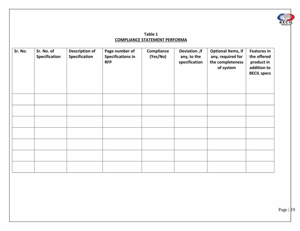
14. Compliance Statement A point by point full compliance statement in respect to all parameters
related to the concerned equipment/items from the respective principle
manufacturers should be submitted in the prescribed format given at
Table 1.
Page | 19
Table 1 COMPLIANCE STATEMENT PERFORMA
Sr. No. Sr. No. of Specification
Description of Specification
Page number of Specifications in RFP
Compliance (Yes/No)
Deviation ,if any, to the
specification
Optional Items, if any, required for the completeness
of system
Features in the offered product in addition to BECIL specs

Page | 20
F. PROPOSAL RESPONSE FORMAT
All the bidders are requested to use the same or similar format as given below while submitting the
commercial bids. The proposal must be submitted strictly in the following fashion as in Table 2.
1. The proposal shall be submitted in the same envelope at the same time, in two distinct parts: a
Technical Proposal and a commercial Proposal.
2. Proposals are to be prepared on standard 8-1/2” x 11” A4 size paper. Foldouts containing charts,
spreadsheets, and oversize exhibits are permissible. The pages should be placed in a binder with tabs
separating the sections of the proposal. Manuals and other reference documentation may be bound
separately. All responses, as well as any reference materials presented must be written in English.
3. Proposals must respond to the RFP requirements by restating the number and text of the
requirement in sequence and writing the response immediately after the requirement statement.
4. Figures and tables must be numbered and referenced in the text by that number. They should be
placed as close to possible to the referencing text. Pages must be numbered consecutively within each
section of the proposal showing proposal section and page number.
5. Proposals shall be based only on the items contained in this RFP and its standard required accessories.
The RFP includes official response to pre-proposal conference questions, addenda, and any other
material published by the BECIL pursuant the RFP. The bidder is to disregard any previous draft
materials and any oral representations it may have received. All responses to the requirements in
Sections (list appropriate section) of this RFP must clearly state whether the proposal will satisfy the
referenced requirements, and the manner in which the requirement will be satisfied.
6. Pricing information shall appear only in the commercial bid and the technical bid shall contain details of
material offered and a compliance statement with reference to the bid document highlighting any
deviations.EMD as well as demand draft towards cost of tender document in case downloaded from
BECIL website shall be part of the technical bid.
TABLE-2
Page | 21
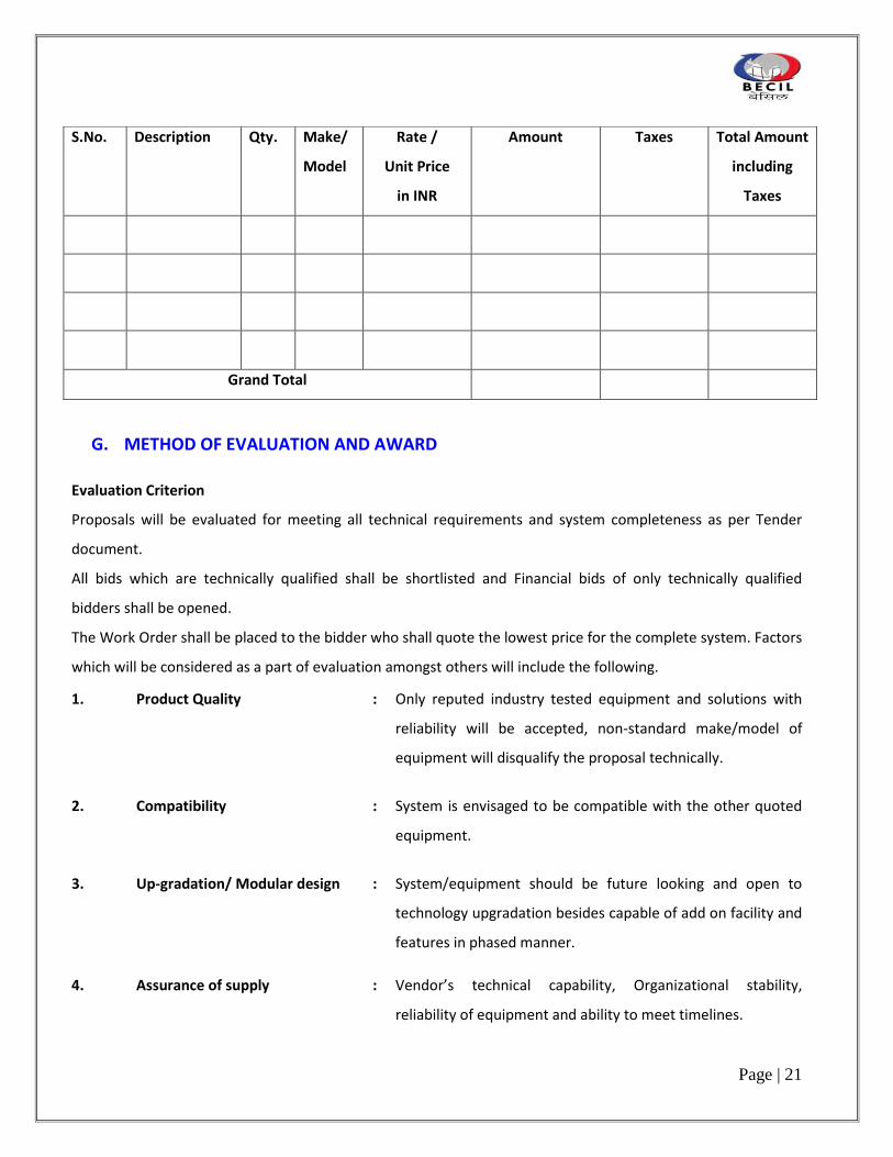
G. METHOD OF EVALUATION AND AWARD
Evaluation Criterion
Proposals will be evaluated for meeting all technical requirements and system completeness as per Tender
document.
All bids which are technically qualified shall be shortlisted and Financial bids of only technically qualified
bidders shall be opened.
The Work Order shall be placed to the bidder who shall quote the lowest price for the complete system. Factors
which will be considered as a part of evaluation amongst others will include the following.
1. Product Quality : Only reputed industry tested equipment and solutions with
reliability will be accepted, non-standard make/model of
equipment will disqualify the proposal technically.
2. Compatibility : System is envisaged to be compatible with the other quoted
equipment.
3. Up-gradation/ Modular design : System/equipment should be future looking and open to
technology upgradation besides capable of add on facility and
features in phased manner.
4. Assurance of supply : Vendor’s technical capability, Organizational stability,
reliability of equipment and ability to meet timelines.
S.No. Description Qty. Make/
Model
Rate /
Unit Price
in INR
Amount Taxes Total Amount
including
Taxes
Grand Total

Page | 22
5. Spares : The bidder has to certify that the spares shall be available for
a minimum period of 5 years after completion of Project.
6. Quality : Equipment stability, guaranteed uptime parameters, life of
equipment.
7. Service : After sales service, availability of spare parts/technical
support, warrantee offered.
8. Cost : Cost of the system as proposed and the apparent future
financial implications, AMC and Total cost of Ownership.
9. Integration
Experience
: Expertise and experience of the bidder in system / sub system
of integration of work of similar nature.
10. Delivery Schedule : Delivery timeline will be critical parameter for evaluation and
final decision.
11. Regulatory : Should meet the Regulatory compliance, Safety requirements,
Environmental objectives.
H. WORKS EXECUTION 1. All the works shall be executed in a professional manner, and in line with established ‘Good Practice’.
2. All internal woodwork shall be treated with anti termite. Timber used for framework shall be kiln
seasoned and should be free from shrinkage, warpage.
3. Provision to be made for additional supports and reinforcement that may be required for stability and
evenness.
4. Contractor to make provisions of all necessary scaffoldings to facilitate high level installations.
Contractor to form openings on partition for services and to seal gaps using silicon sealant.
5. Where the use of spring loaded auto closing hinges is specified, the same shall be installed strictly as
per manufacturer’s guidelines and relevant tools required for the same.

Page | 23
6. All drawings to be referred while quoting.
7. All woodwork and fabric shall be supplied with fire retardant treatment.
I. BECIL OBLIGATIONS
BECIL reserves the right to accept any bid, reject any or all bids and to annul the bidding process at any
time prior to the award of the contract without there by incurring any liability to the affected
bidder/bidders or any obligations to inform to the affected bidder/bidders of the grounds for BECIL’s
action.

Page | 24
SECTION II
BILL OF MATERIAL
1) CIVIL & INTERIOR WORK
2) ELECTRICAL WORK
3) HVAC
3A) PAC
4) MODULAR
5) PLUMBING
6) IT NETWORKING
7) SECUIRTY SYSTEM

Page | 25
1. CIVIL & INTERIOR WORK

Page | 26
S.NO DESCRIPTION UNIT QTY
MAKE /
MODEL
Rate Amount Taxes Total Amount including
Taxes
A.00 CIVIL WORKS
A.01
Site Clearance and Cartage: General housekeeping of site including regular removal of malba, debris and waste material and keeping the site clean and workmanlike. The contractor shall have freedom to reutilize (in other projects)/dispose off the materials, fittings and fixtures removed from the site Contractor to verify areas of demolition at site. The rate to include the labour, cartage etc.
LS 1
A.02
Demolition of Existing Brick Walls, 115 mm: Demolition and removal of existing brick walls, 115 mm thick and cartage of the same to the nearest dumping grounds. The contractor shall have freedom to reutilize (in other projects)/dispose off the materials, fittings and fixtures removed from the site.
SqM 390
A.03 Demolition of Existing Brick Walls, 230 mm: As per item A.2 above but the walls to be 230 mm thick.
SqM 10.56
A.04
Dismantling of Existing Floors: Dismantling and removal of existing floor and entire base of cement mortar in any thickness and cartage of the same to the nearest dumping grounds. The contractor shall have freedom to reutilize (in other projects)/dispose off the materials, fittings and fixtures removed from the site.
SqM 140
A.05
Dismantling of Existing Door Frames: Dismantling and removal of existing door frames and cartage of the same to the nearest dumping grounds. The contractor shall have freedom to reutilize (in other projects)/dispose off the materials, fittings and fixtures removed from the site.
Nos 45
Page | 27
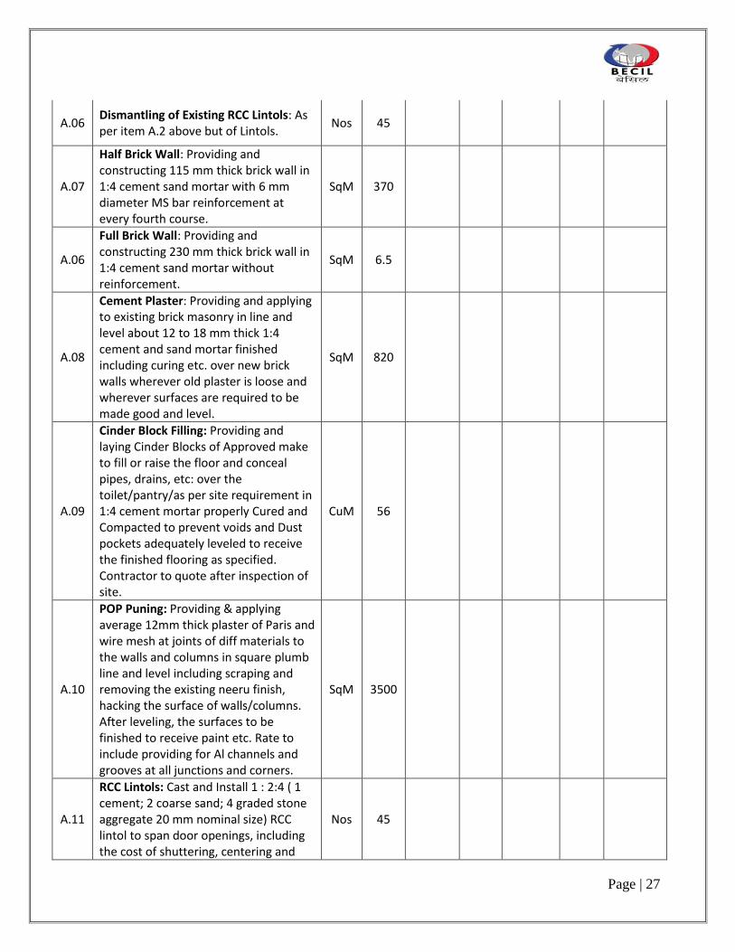
A.06 Dismantling of Existing RCC Lintols: As per item A.2 above but of Lintols.
Nos 45
A.07
Half Brick Wall: Providing and constructing 115 mm thick brick wall in 1:4 cement sand mortar with 6 mm diameter MS bar reinforcement at every fourth course.
SqM 370
A.06
Full Brick Wall: Providing and constructing 230 mm thick brick wall in 1:4 cement sand mortar without reinforcement.
SqM 6.5
A.08
Cement Plaster: Providing and applying to existing brick masonry in line and level about 12 to 18 mm thick 1:4 cement and sand mortar finished including curing etc. over new brick walls wherever old plaster is loose and wherever surfaces are required to be made good and level.
SqM 820
A.09
Cinder Block Filling: Providing and laying Cinder Blocks of Approved make to fill or raise the floor and conceal pipes, drains, etc: over the toilet/pantry/as per site requirement in 1:4 cement mortar properly Cured and Compacted to prevent voids and Dust pockets adequately leveled to receive the finished flooring as specified. Contractor to quote after inspection of site.
CuM 56
A.10
POP Puning: Providing & applying average 12mm thick plaster of Paris and wire mesh at joints of diff materials to the walls and columns in square plumb line and level including scraping and removing the existing neeru finish, hacking the surface of walls/columns. After leveling, the surfaces to be finished to receive paint etc. Rate to include providing for Al channels and grooves at all junctions and corners.
SqM 3500
A.11
RCC Lintols: Cast and Install 1 : 2:4 ( 1 cement; 2 coarse sand; 4 graded stone aggregate 20 mm nominal size) RCC lintol to span door openings, including the cost of shuttering, centering and
Nos 45

Page | 28
steel reinforcement (8/10 mm dia)
A.12
Granite Counters in Pantry/Toilet/Kitchen: Constructing RCC platform of 75 mm thick. with adequate reinforcement including shuttering, curing etc. in 1:2:4 concrete, in toilet/pantry/kitchen with 115 mm thick brick upstands as required and directed, at 800-850 mm height and depth 600/550 mm width. Finish with 20 mm thick polished Granite, with machine cut & polished edges including splash-back and fascia all within 200 mm height all laid/fixed with rich cement mortar mix. Base rate of Granite is Rs 125/Sq.Ft.
RM 9.35
A.13
Water Proofing: Provide water proofing for RCC slab and brick walls under finished floor level and other area as directed by the Architect with Tape Crete 735 or equivalent water proof surface coating system. Including cleaning of surface to remove all dust, foreign matter, loose materials etc. prior to application of waterproof coating. Depressions, if any in the slab to be filled and leveled with Tape Crete –735 or equivalent fillers at proprietary defined ratio. Entire application to be executed as per proprietary procedures recommended for the coating application.
SqM 50
A.14
Cement Sand Leveling Screed: To provide and lay approx 40-mm thick top layer of 1:2:4 concrete cement finish to provide a finished horizontal surface, ready to receive floor finishes, tiles, carpets etc.
SqM 190
A.00 Summary Civil Works
B.00 DOORS

Page | 29
B.01
FRAMELESS GLASS DOOR TYPE - 1: Providing and fixing twin leaf 12mm toughened glass door. Rates to be inclusive of all necessary hardware fittings including SS handle, lock, stopper and stay. Overall door size to be 1800x2100 mm. Hardware set to be as follows: GEZE Pull handle pair, 38 mm dia of length 2000 mm. • GEZE FS 923 Floor Spring spring stainless steel cover. GEZE P 010 Top Patch, GEZE Bottom Patch P 020 Bottom patch • GEZE L 010 Patch Lock • Top Pivot TLG 502 • Door Stopper GEZE YDS 010 • GEZE S.S.304 Pull Handle of size 38mm x 1000 mm
Nos 4
B.02
FRAMELESS GLASS DOOR TYPE - 2: Providing and fixing twin leaf 12mm toughened glass door. Rates to be inclusive of all necessary hardware fittings including SS handle, lock, stopper and stay. Overall door size to be 2000x2100 mm. Hardware set to be as follows: GEZE Pull handle pair, 38 mm dia of length 2000 mm. • GEZE FS 923 Floor Spring spring stainless steel cover. GEZE P 010 Top Patch, GEZE Bottom Patch P 020 Bottom patch • GEZE L 010 Patch Lock • Top Pivot TLG 502 • Door Stopper GEZE YDS 010 • GEZE S.S.304 Pull Handle of size 38mm x 1200mm For GEZE enquiry Contact Kapil – 9899000075
Nos 1

Page | 30
B.03
FRAMELESS GLASS DOOR TYPE - 3: Providing and fixing twin leaf 12mm toughened glass door. Rates to be inclusive of all necessary hardware fittings including SS handle, lock, stopper and stay. Overall door size to be 1000x2100 mm. Hardware set to be as follows: GEZE Pull handle pair, 38 mm dia of length 2000 mm. • GEZE FS 923 Floor Spring spring stainless steel cover. GEZE P 010 Top Patch, GEZE Bottom Patch P 020 Bottom patch • GEZE L 010 Patch Lock • Top Pivot TLG 502 • Door Stopper GEZE YDS 010 • GEZE S.S.304 Pull Handle of size 38mm x 1200 mm
Nos 25
B.04
FLUSH DOORS LAMINATED 1000 MM: P&F Semi solid core laminated door formed out of 25X 100 mm wide Marandi/CPTW frame 6 mm thick ply skins, and faced both sides with 1 mm thick laminate to form overall thickness of 40/50 mm. 50X 100/125 section Maple wood chowkhat. All wood work to be finished in and polished to Architect’s approval. All handles to be in brushed SS finish of Dorset or equivalent make and Architect’s approved model. Complete with all hardware including locks, Ingersol Rand door closer, door stoppers etc as required. Overall door size to be 2100/240 mm x 750/1000 mm. Hardware set to be as follows: • GEZE DCR 7003H Size 3Concealed Door Closer HO • GEZE 100 mm x 75 mm x 3 mm ball bearing hinges, CE Certified, Fire Tested in satin stainless steel finish grade 304. 4 Nos. • 28P3.60 Mortise Lock SS lever handle with 500/1000 series Cylinder.
Nos 7

Page | 31
B.05
FLUSH DOORS LAMINATED, 900MM: P&F Solid core laminated door as per item number B.3 above but of 900 mm width.
Nos 2
B.06
FLUSH DOORS LAMINATED 1500 MM: P&F Solid core laminated door as per item number B.3 above but size to be 2400 mm x 1500 mm. The door will be twin leaf
Nos 1
B.07
FIRE RATED DOOR WITH PANIC BAR: P&F Fully insulated Steel Composite light Flush Fire Doors with 2 hour fire rating in conformance with IS 3614 Part 2 and BS 476 Part 22. Door frames to be double rebate profile of 143 mm width and 57 mm height manufactured from 16 gauge galvanized steel, profile to have bending radius of 1.4 mm supplied in Knock down form for butt joint assembly at site. Door Shutter in 46 mm thick manufactured from two 18 gauge galvanized steel sheets lock seam jointed at stile edges to form a double skin fully flush shell. Infill of Properitory insulation material to be provided for structural rigidity & additional reinforcements & sound Insulation for all hardware fixtures as required. Complete with all harware including locks, door closer, door stopper etc as reqd.B102 Overall door size to be 2100 x 1200 mm. Hardware set to be as follows: • GEZE Heavy Duty Door Closer NSK – 680 • SS Hinges,1250 mmx75 mmx3 mm hinges, 4 Nos. • Dorset SS lever handle with mortise lock. Panic Bar with single point rim panic latch.
Nos 4
B.08
FLUSH DOORS, LAMINATED, WITH VISION PANEL 1000mm: P&F same as itme No.B.06.Overall door size to be 2400/2550 x 1000 mm. Refer to Door Schedule drawing
Nos 23

Page | 32
B.09 FLUSH DOORS 750 MM: P&F Flush door specification same as exisiting toilet doors.
Nos 14
B.10
LAMINATED SHUTTERS FOR SHAFT: Overall specifications to be same as item no D.05except the door will be faced with 1 mm thick laminate, as per architects design and the required harware set shall be as per Item no D.5
Nos 10
B.00 Summary Doors
C.00 JOINERY
C.01
FULL HEIGHT FRAMELESS GLAZED TOUGHENED PARTITION: Fabricating and fixing of 12mm thk. toughened Glass partition with concealed fixing arrangement in floor and ceilings as/architect’s instructions. The rate shall include sealing all joints with with non staining clear silicon sealant/UV treated, machine cut, machine polished edges, tapers to design.
SqM 80
C.02
FULL HEIGHT GYPSUM BOARD PARTITION: Providing and fixing 75 mm thick gyp-board partition faced both sides with 12 mm thick, tapered edge gypsum board (Conforming to IS-2095-1982), screw fixed with dry wall screw of 25 mm at 300 mm centers to either sides of 48 mm GI studs (.55 mm thick), having one flange of 34 mm and other flange of 36 mm, placed at 610 mm center to center (both ways) in 50 mm floor and ceiling channels of 32 mm section. Skirting, door junction and material transition sections to be in hardwood frame 50 x to provide 10x10 grooves at all ends. If any hardwood sections are provided, these are to be coated all over with 2 or more coats of viper anti-termite/fire retard paint. Inside voids to be filled with 50 mm thick panels of glass wool/ rock wool. All gypsum board edges to be protected with aluminum angles. Partition to include laminated skirting on both sides as required.
SqM 381

Page | 33
C.03
COLOR BACK GLASS PANELLING: Form paneling on brick wall and columns with 8 mm thick ply faced front side with 10 mm thick non toughened glass. Back of the glass to be painted with duco paint of Architect’s approved shade. Ply face to be painted with color to match the glass. Glass to be fixed with dow corning/ 3M high bond tape of adequate bond strength, to laminated strips affixed to the backing ply. Overall specifications, supporting and edge treatment of glass. Saint Gobain Planlaque only to be used.
SqM 25
C.04
LAMINATED PANELING: Form paneling on a backing of 50x50mm hardwood sections framework at 600 x 600 mm c/c or on solid partitions and faced front side with 8 mm thick ply and finished with 1 mm thick laminate as per architect’s approval. Provide for 10 mm x 10 mm grooves as required finished in laminate as specified by Architect.
SqM 155
C.05
FLUTES ACOUSTIC PANELLING: Providing and Fixing Channeled Decosonic Flutes perforated panels of width 128mm, thickness of 16mm and length 2440 mm made of a high density particle board substrate with a laminated facing as per the wooden / white finish and a woven fleece layer on the reverse side. The boards shall have a special perforation pattern where the visible surface has a “Helmholtz” fluted perforation of 4mm width and 28mm of visible panel each. The panels shall provide a minimum sag resistance of RH90 and a fire rating class of 1 as per Part 7 of BS 476. The edges of the panels shall be “tongue-and-grooved” to receive special clips for installation. The back of the perforated panel shall have sound absorbing non-woven acoustical fleece. The panels shall be mounted on special aluminium
SqM 120

Page | 34
splines using clips approved by the Architect/ Engineer-in-Charge. INSTALLATION: Install wooden battens (provided by others) of section 50mmx50mm or as approved by the Architect on the solid wall horizontally using screws and plugs at spacing of 600mm centre-to-centre. Screw the aluminium extruded keel for DecosonicFlutes (GTPT001) over the lowest and second wooden batten at an on-center distance of 600mm. Install the first set of wooden panels by inserting the clips for border Decosonic Flutes (GTPT002) and insert the groove of the panel into the projecting flange of the aluminium clip. Continue installing rows of panels by inserting the tongue into the groove of the earlier inserted panel and progressively installing clips for inside Decosonic Flutes (GTPT003) into the next keel till the actual height is achieved. Use clips for border Decosonic Flutes (GTPT002) to finish off the installation. Finish off the edges using wooden moulding of matching colour (provided by others). Approved Make-Decosonic™ or equivalent.
C.07
MIRROR PANELING: As per item number C.5 below but faced with 6mm Mirror fixed on 10mm thk ply to be flush in level with adjoining surfaces. Cost to include bevelling, cutting etc of mirror.
SqM 10
C.08
MDF PANELING WITH DUCO PAINT: As per item number C.1 but faced with 12mm thk MDF instead of gypsum board and ready to receive duco paint finish as per architect’s approval.
SqM 8
Page | 35
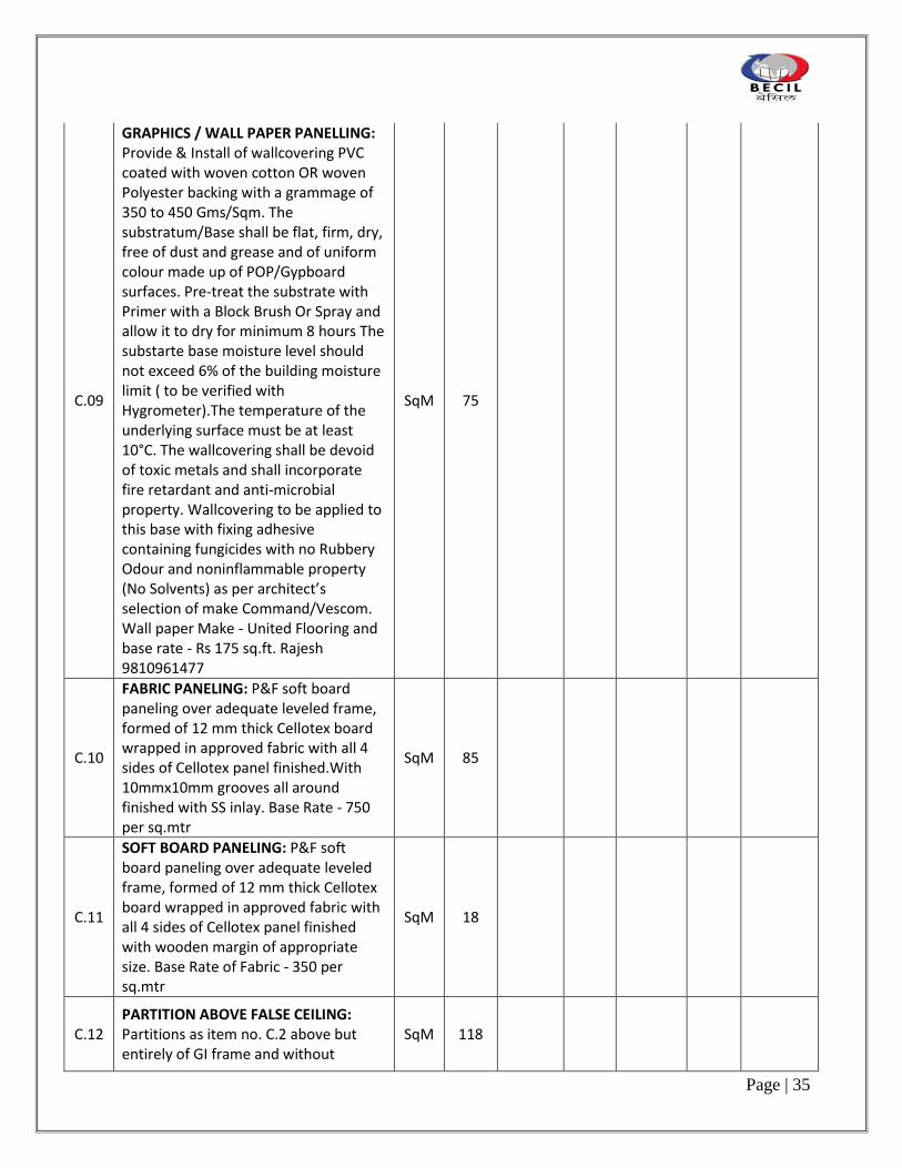
C.09
GRAPHICS / WALL PAPER PANELLING: Provide & Install of wallcovering PVC coated with woven cotton OR woven Polyester backing with a grammage of 350 to 450 Gms/Sqm. The substratum/Base shall be flat, firm, dry, free of dust and grease and of uniform colour made up of POP/Gypboard surfaces. Pre-treat the substrate with Primer with a Block Brush Or Spray and allow it to dry for minimum 8 hours The substarte base moisture level should not exceed 6% of the building moisture limit ( to be verified with Hygrometer).The temperature of the underlying surface must be at least 10°C. The wallcovering shall be devoid of toxic metals and shall incorporate fire retardant and anti-microbial property. Wallcovering to be applied to this base with fixing adhesive containing fungicides with no Rubbery Odour and noninflammable property (No Solvents) as per architect’s selection of make Command/Vescom. Wall paper Make - United Flooring and base rate - Rs 175 sq.ft. Rajesh 9810961477
SqM 75
C.10
FABRIC PANELING: P&F soft board paneling over adequate leveled frame, formed of 12 mm thick Cellotex board wrapped in approved fabric with all 4 sides of Cellotex panel finished.With 10mmx10mm grooves all around finished with SS inlay. Base Rate - 750 per sq.mtr
SqM 85
C.11
SOFT BOARD PANELING: P&F soft board paneling over adequate leveled frame, formed of 12 mm thick Cellotex board wrapped in approved fabric with all 4 sides of Cellotex panel finished with wooden margin of appropriate size. Base Rate of Fabric - 350 per sq.mtr
SqM 18
C.12 PARTITION ABOVE FALSE CEILING: Partitions as item no. C.2 above but entirely of GI frame and without
SqM 118

Page | 36
skirting, to be installed over false ceilings.
C.13
ALUMINIUM SKIRTING: Fabricating and fixing 50 mm High Aluminium skirting with al. strip cover over partition & pop surface :‐ providing and fixing 1.0 to 1.5mm thick 50mm high extruded anodized aluminum skirting as per manufacture spec with Aluminium Capping. Contractor to ensure ply backing w/o additional cost for fixing of the skirting. Corners to be buffed to Chamfer Details and to be installed neatly without Corner capping. As per Architect Approval (Alloy Make)
RM 1800
C.14
PELMET: Fabricate and install pelmet made of 19 mm thick board, 600 mm to 900 high and with approx 400 angled width and in line with external glazing as per details of Architect. Rate to include finishing exposed surfaces of the Pelmet with enamel paint of approved shade. Pelmet to be ready to receive blinds.
RM 230
C.15
RECESSED PELMET FOR SCREENS: As per item no. C.13 below but of width 250 mm and height 250 mm, cut into gypsum false ceilings and ready to receive projection screen.
RM 2
C.16
LAMINATED SHELVES: Fabricate and install 250/300 mm deep, 1000/1500 mm long Laminated shelves. Shelf to be mounted on to existing partitions, walls etc as directed with concealed fixing detail. Shelves to be fabricated with 2 Nos. 19 mm thick board, with 19 mm filler pieces, faced all sides with 1 mm thick laminated.
Nos 10

Page | 37
C.17
WORK TOP COUNTER LAMINATED: Fabricating & fixing up to 750 mm deep and 720 ht worktop counter formed out of 25 mm thick mdf board faced with .8mm thick post formed laminate of approved shade. Front edge of counter to be post‐ formed beveled waterfall edge or as per other designs provided by the architect. Adequate support to be provided at regular intervals. Cutouts for fliptops/grommets to be provided as per architect’s instructions.
SqM 22
C.18
PLY BLANKING ABOVE FALSE CEILING: Fabricate and install 6 mm ply divider above false ceiling to sit against the external glazing. Ply face to be enamel painted in black color.
SqM 210
C.19
WINDOW CILL: Fabricate and install 250-350 mm wide, window cill along external windows. Cill to be constructed out of 12 mm Commercial board, and faced with 1 MM thick Laminate to Architect’s approval.
RM 230
C.00 Summary Joinery
D.00 BUILT IN STORAGE
D.01
FULL HEIGHT STORAGE, LAMINATED: Fabricating and fixing full height storage cupboards as per details. Top, bottom and shelves to be made out of 19 mm thick pre-laminated laminated commercial board with Ane grey wood lipping. Back to be provided of 8 mm thick commercial ply. Shutters to be made out of 19 mm thick board faced with 1.00 mm thick laminate. All internal surfaces to be faced with 0.8 mm thick laminate of approved shade. External surfaces finished on exposed sides with 1 mm thick laminate. Complete with all necessary fittings like hinges, ball catchers, tower bolts, locks, handles, adjustable shelves etc. as per directions of Architect. Cupboard depth of 400-450 mm. Adjustable shelves to be supported on half cut; 10 mm dia s.s
SqM 96

Page | 38
glass pins. (Laminate shade from Safedecor)
D.02
LOW HEIGHT STORAGE LAMINATED: Form low height storage of 750 mm ht. as per details and specifications of item no D.1 above but with only Shutter to be formed out of 19 mm thick commercial board and faced with 1mm thick laminate. Outer frame to be formed for hanging shutters only. No internal box inclusive all hinges, locks and other hardware as per architects approval in SS
SqM 39
D.03
OVERHEAD STORAGE LAMINATED: Form as per item D.1 above but of height 750/900 mm and hung onto wall. All exposed surfaces faced with 1 mm thick laminate (plain/metallic). Storage to include shutters and also open shelves. (Laminate shade from Safedecor)
SqM 35
D.04
Under Counter Storage: Fabricate and install storage module under RCC counters in toilet and pantry or under worktop counters. Shutters of storage unit to be formed out of 19 mm thick BWP ply and faced with 1 mm thick laminate (plain). Shutters to incorporate 20mm SS groove at all locations. Shutters to be hung on concealed hard wood frame out of 50 x 50 section as per details. Provide one shelf, made of 19 mm thick BWP ply, polished to architect’s approval. Complete with all necessary fittings like hinges, ball catchers, tower bolts, locks, handles, adjustable shelves etc. as per directions of Architect. Inside surfaces to be finished with 1 mm thick laminate. Cupboard depth of 600- 750 mm.
SqM 12

Page | 39
D.05
PERSONAL LOCKER UNITS (PLU) Providing and Fixing Personal Locker Units of High Pressure Laminate of (Laminate shade from Safedecor) make of following External Dimensions As approved by Architect. Width – 15” Height – 15”Depth – 18” The Lockers to be installed as stacks in combinations as per the site requirements at different locations.
SqM 53
D.06
SLOTTED ANGLE RACKS: Provide and Install open Slotted Angle Racks of MS upto a height of 2100mm and depth of 600mm.
SqM 29
D.00 Summary Built In Storage
E.00 MISCELLANEOUS ITEMS
E.01
FIRE SIGNAGE, LARGE: Providing and Installing Double sided Glow signs- fire exit and directional signage – of GEO/GLOLITE make at locations indicated by Architect including all exit points and directional signage. Size of Glow signage to be 300 mm x 100 mm.
Nos 6
E.02
FIRE SIGNAGE, SMALL: Providing and installing fire extinguisher signage as per item number e.1 above but of size, 100 x 100 mm
Nos 18
E.03
LOGO SIGNAGE: Fabricate and install Company corporate logo as per company supplied artwork. Logo to be in 15/18mm thk 3 D Acrlic/ MDF Letter cuts . Signage of owner’s Logo, Typeface etc. as required. Size 1050x450mm approx. Final size post approval
PS 1
E.04
INTERNAL SIGNAGE WASHROOMS: Provide and install internal signage for toilets and pantry. Signage to be in brushed stainless steel finish grade 316. Overall size of 150 mm x 150 x 2 mm approx.
Nos 10

Page | 40
E.05
INTERNAL SIGNAGE – AUDITORIUM / MEETING ROOMS: Provide and install internal signage for meeting Rooms. Signage to be printed on 250 x 250 mm sparkle 3M film and adhered to glass partition of meeting room.
Nos 3
E.06
FROSTING FILM: Provide and apply 3M make frosting film, sparkle finish, on glazed partitions doors etc. in patterns as provided by the Architects. Base Rate - 850 sq.mtr
SqM 30
E.07
GLASS SHELVES: Provide and install 10 mm thick glass shelves of size 400 x 550 mm. Shelves to be installed on SS glass pins and edges of glass to be machine ground and polished.
Nos 5
E.08
MARKER TRAYS: Fabricate and Install laminate marker tray of size 500 mm x 100 mm x 50 mm, fabricated out of 25 mm thick boards faced with 1 mm thick laminate. Conceal mounted on existing partitions, walls etc.
Nos 2
E.09
SS STRIP INSERTS: Provide and fix 4 mm x 6 mm Stainless Steel strips, glue affixed to underlying surfaces of veneer/laminate/ fabric paneling. (Make Alloy)
RM 45
E.10 MAGAZINE RACK : Fabricate and Install magazine rack as per detail drawing
Nos 1
E.11
SS STRIP CARPET PROTECTOR: P&F L angle Stainless Steel strip at all junction points between hard floor and carpet. (Make Alloy)
RM 50
E.12
SS PLANT CONTAINERS: Provide and Install Stainless Steel plant containers, of size 400 mm high and 400 mm dia as per approved samples.
Nos 16
E.13
EXPANSION JOINT: Providing & installing Rigid joint strip of aluminium alloy clear anodized. Model No: W70. For wall, floor and ceiling expansion joints. (
Rmt. 105

Page | 41
E.14
LOOKING MIRRORS: P&F Looking Mirrors as per Item E.26and without frames, and asbestos vapor barrier etc. including concealed fixing detail, pelmet for concealed light fixtures and Wooden Panelling for Mounting the Mirror and Other Support Structures. Cost Shall Also Include the d‐mirroring and Frosting of Mirrors as per the Approved Design. Pelmet for light fixtures to be painted white from the inside.
SqM 24
E.15
ALUMINIUM JALI: Providing and Fixing of aluminium jaali/mesh for building windows (fixed and openable) to block access from the window. Opening to not exceed more than 75mm.
SqM 300
E.00 Summary Miscellaneous Items
F.00 FLOOR & WALL FINISHES
F.01
VITRIFIED TILE FLOORING 1: Providing and laying vitrified tile flooring of size 600 mm x 600 mm, in locations as directed, laid to required slope in 1: 4 cement coarse sand mortar up to 50 mm thick. With tile grout joints of approved width finished, in colored tile grout, Roff chemicals/ bal or equivalent m+B70ake. Base Rate -125 per sq.ft.
SqM 180
F.02
CARPET TYPE -1 : Provide and lay nylon carpet tiles (size 2x2) of make United Flooring. Shade to be finalized by Architect. Base Rate - 175 per sq.ft. Rajesh 9810961477
SqM 190
F.03
CARPET TYPE -2 : Provide and lay nylon carpet tiles (size 2x2) of make United Flooring. Shade to be finalized by Architect. Base Rate - 150 per sq.ftRajesh 9810961477
SqM 160
F.04
CARPET TYPE -3 : Provide and lay nylon carpet tiles (size 2x2) of make United Flooring. Shade to be finalized by Architect. Base Rate - 130 per sq.ftRajesh 9810961477
SqM 1250

Page | 42
F.05
KOTA STONE FLOORING: Provide and lay 19 mm thick, machine cut and polished Kota Stone flooring upon a bed of average 20 mm thick cement mortar, 1:4. All jointed to be sealed with roff chemical or equivalent grout of matching shade and floor to be covered with POP and polythene until handover of the site. Inclusive of grinding and polishing of floor.
SqM 90
F.06
ITALIAN MARBLE FLOORING/DESIGNER TILE: Provide and lay 19 mm thick, machine cut and polished Italian marble‐ flooring upon a bed of average 20 mm thick cement mortar, 1:4. All jointed to be sealed with roff chemical or equivalent grout of matching shade and floor to be covered with POP and polythene until handover of the site. Laticrete Impregnator 511 to be applied on top of stone after polishing and before waxing the stone. Vendor to ensure Protection of marbleflooring till the final hand over workplace. The surface of stone should be treated with Latamiracle 511 Porous Plus . Base price Rs 350/sqft.
SqM 60
F.07 RUBBER MAT FLOOR: P&I rubber mat in battery and Ups room as required.
SqM 55
F.08
ACCESS FLOOR: Providing and fixing access floor panels adjustable (300+/- 20mm) height under floor construction of light weight grade (15 KN/m2) UDL panels of 600x600x31mm thickness faced with 3 mm thick anti stat laminate on top, with BTW stained black edge lipping of tapered profile and aluminum sheet at the bottom. Hewetson make or equivalent. Adjustable jacks to be manufactured from pressed formed corrosion resistant galvanized steel, placed on the pedestal (of axial load 22.5 KN), zinc plated consisting of anti-vibration head cap with cruciform up-stand and four panel locating studs, etc. complete. The rate to include cutting tiles for access to
SqM 250

Page | 43
services and also includes supply of 2 nos. of vacuum tile lifter. (
F.09
DESIGNER VINYL FLOORING: : P&I Vinyl flooring, commercial grade, of O/A thickness 3.3 mm and wearlayer thickness of 0.62mm and weight 2795 g/sqm. Floor to be fixed with proprietary recommended adhesive. Rate to include self leveling screed (of Bal chemicals) layer of 1 to 2mm thkness to achieve zero level. Max deflection for a 2M spirit level : 7mm, for a 0.20M spirit level : 2mm. Range to be considered United Flooring. Base Rate - INR 110
SqM 450
F.10
LAMINATED FLOORING: P&I Harwood parquet flooring, commercial grade, composed of water repellant HDF panels with direct pressure laminate and protective laminate based abrasion resistant film. Thickness of panels to be 11mm including underlay. Rate to include underlay, floor transition strips and all accessories as required. Base rate of the flooring: Rs 150/sq ft. Make United Flooring
SqM 36
F.11
KOTA STONE SKIRTING: Provide and lay 19mm thk Kota Stone Skirting, 100 mm high, on walls / columns in lengths specified by Architects.Skirting to be flush with finished surface of walls / columns. Include breaking and removing existing plaster / skirting and applying up to 12 mm thick 1:3 (1 cement: 3 coarse sand) cement mortar backing.
RM 56
F.12
VITRIFIED TILE SKIRTING: Provide and Fix Vitrified Tile Skirting, 100 mm high, on walls / columns in lengths specified by Architects, of overall specifications as per item no F.1 above. Skirting to be flush with finished surface of walls / columns. Include breaking and removing existing plaster / skirting and applying up to 12 mm thick 1:3 (1 cement: 3 coarse sand) cement mortar
RM 53

Page | 44
backing. MAKE - KASA DÉCOR
F.13
ITALIAN SKIRTING: Provide and lay 19 mm thick, 100 MM high machine cut and polished Italian marble skirting, of overall specification as per item no.H.4 above Skirting to be flush with the finished wall surface, including breaking and removing of existing plaster and applying rich plaster backing. MAKE - KASA DECOR
RM 36
F.14
CERAMIC WALL TILES TYPE : Providing and fixing plain white 600x300 ceramic tiles, laid in 1:3 cement coarse sand mortar, up to 12 mm thick for dado upto ceiling height in pattern indicated by Architect in toilets / pantry and other locations with mortar as item F.15 and thickness necessary to bring the surface plumb and minimize cut tiles/ joints. Tile joints to be finished with approved make tile grout in thickness as directed. Base Rate - 75 per sq.ft. Make Kasa Décor
SqM 176
F.15
ENAMEL PAINT: Providing and applying enamel paint to Wooden surface, gypsum walls, POP puning, Gypsum ceiling and existing plastered ceiling, including paint putty, base coat as pre manufacturers recommendations and finishing with 2/3 coats of plastic / acrylic emulsion paint of approved color and make. Surface coating to be achieved as per manufacturer’s recommendations for coverage of paint.
SqM 605
F.16
EMULSION PAINT: Providing and applying plastic/acrylic light textured emulsion paint with putty finish incl. to gypsum walls, POP puning, Gypsum ceiling and existing plastered ceiling, including paint putty, base coat as pre manufacturers recommendations and finishing with 2/3 coats of plastic / acrylic emulsion paint of approved color and make. Surface coating to be
SqM 6500

Page | 45
achieved as per manufacturer’s recommendations for coverage of paint.
F.17
DUCO PAINT: Providing and applying Duco paint finish with two pack, epoxy resin based paint. To be applied as per manufacturer’s recommended method of application with PU coat/finish on top.
SqM 15
F.18
SPECTRUM PAINT: Providing and applying Spectrum /textured paint wall finished. To be applied as per manufacturer’s recommended method of application.
SqM 25
F.00 Summary Floor & Wall Finishes
G.00 FALSE CEILING
G.01
GYPSUM BOARD CEILING: P&F 12 mm thick Gypsum board to G.I. framing perfect in level including making grooves at the junction of ceiling and walls/columns/partitions etc., making rectilinear stepped profiles, cut out for light fittings, A/C grills, speakers, services etc etc. and including providing and fixing necessary G.I./wooden frame supports for the above fixtures and additional suspenders to hang the same independently. G.I. frame to consist of proprietary supplied frames and as per manufacturers recommendations, suspended from RCC slab with dash fasteners / or anchored to exposed reinforcement of structural slab by means of GI proprietary angles. Gypsum board fixed with proprietary supplied fixing devices and including top coat and finished to receive paint. All complete including 100/150 wide return air slits & A/C boxing wherever indicated. MAKE - BORAL
SqM 1550

Page | 46
G.02
DESIGNER CEILING: Of overall specification as per item noG.1 above but in stepped / designed profile as per details in specified areas formed of pre-cast slabs/ cast in situ POP stepped profiles including coves at various levels, including cut outs for light fixtures, speakers, services etc as indicated in reflected ceiling plans, all to approval of Architects.
SqM 190
G.03 TILE GRID CEILING Providing and Fixing mineral fiber ceiling consisting of tiles and grids as follows:
SqM 610
1. BORAL 0.7 NRC Clima Plus, 600 x 600 mm nominal size range or equivalent with tegular edge.
2. Ceiling grid to be of hot dip galvanized steel system, power coated white finish, including main runners, cross tees and wall angles. Profile to be used is, 15 mm T Grid.
3. Main runners to be spaced at 1200mm centers, fixed to soffit by approved hangers at 1200 mm distance. First and last hangers should not be at a distance of more than 450 mm from the adjacent wall. 600 x 600 mm module to be formed by fixing 600 mm cross tee between center of 1200 mm cross tees. Wall angels to be secured to wall at 450mm centers.
Page | 47
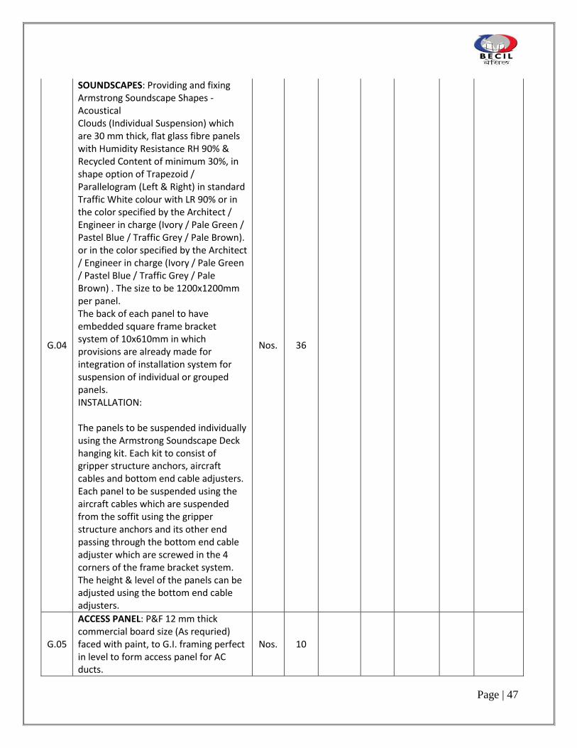
G.04
SOUNDSCAPES: Providing and fixing Armstrong Soundscape Shapes ‐ Acoustical Clouds (Individual Suspension) which are 30 mm thick, flat glass fibre panels with Humidity Resistance RH 90% & Recycled Content of minimum 30%, in shape option of Trapezoid / Parallelogram (Left & Right) in standard Traffic White colour with LR 90% or in the color specified by the Architect / Engineer in charge (Ivory / Pale Green / Pastel Blue / Traffic Grey / Pale Brown). or in the color specified by the Architect / Engineer in charge (Ivory / Pale Green / Pastel Blue / Traffic Grey / Pale Brown) . The size to be 1200x1200mm per panel. The back of each panel to have embedded square frame bracket system of 10x610mm in which provisions are already made for integration of installation system for suspension of individual or grouped panels. INSTALLATION: The panels to be suspended individually using the Armstrong Soundscape Deck hanging kit. Each kit to consist of gripper structure anchors, aircraft cables and bottom end cable adjusters. Each panel to be suspended using the aircraft cables which are suspended from the soffit using the gripper structure anchors and its other end passing through the bottom end cable adjuster which are screwed in the 4 corners of the frame bracket system. The height & level of the panels can be adjusted using the bottom end cable adjusters.
Nos. 36
G.05
ACCESS PANEL: P&F 12 mm thick commercial board size (As requried) faced with paint, to G.I. framing perfect in level to form access panel for AC ducts.
Nos. 10

Page | 48
G.00 Summary Ceilings
H.00 LOOSE FURNITURE
H.01
RECEPTION DESK: Supply and installing reception desk as per architects design. Reception desk to consist of front and side units along with storage units. Front unit to have additional horizontal surface at ht. 1200 mm above the floor level. Top & sides finished with 100 mm thick edge polished Duco to Architect’s approval. Table to have wire management detail, if required. O/A dimensions as per drawing All drawers to have White Duco fronts on all sides formed of 19 mm thick board and 12 mm thick lipped sides, and back and 6 mm thick comm. ply bottom. Duco to be finished with PU top coat. Drawers to be hung on Aries nylon glide and be centrally lockable. Provide SS Continous recessed handles from Hettich for drawer handles
Nos 1
H.02 PODIUM FOR AUDITORIUM: Providing & Placing in position podium as per approved design.
Nos 1
H.03 ANTIQUE CREDENZA: Supply & Installing Credenza as per dwg.
Nos 2
H.04 SEATING BENCH: Supply and installing reception desk as per architects design.
Nos 1
H.00 Summary Loose Furniture
I.00 BLINDS
I.01 Roller Blinds Make WinFab SqM 385
I.00 Summary Blinds
K.00 COST SUMMARY: CIVIL & INTERIOR WORKS
A.00 Summary Civil Works
B.00 Summary Doors
C.00 Summary Joinery
D.00 Summary Built In Storage
E.00 Summary Miscellaneous Items

Page | 49
F.00 Summary Floor & Wall Finishes
G.00 Summary Ceilings
H.00 Summary Loose Furniture
I.00 Summary Blinds
K.00 Total Cost of Civil & interior Works

Page | 50
2. ELECTRICAL WORK

Page | 51
Sl.No.
Description Unit Qty Make/Model
Rate Amount Taxes Total Amount Including Taxes
A. POINT WIRING
All Bulbs/any other consumables should be branded.It should have atleast one year replacement guarantee.
Point wiring rates are inclusive of 2 x 2.5 + 1 x 1.5 sq mm FRLS PVC insulated stranded copper conductor wires for circuit.
All sockets to be checked with a Check Plug socket tester for live-neutral reverse, no earth,neutral fault, live earth reverse, neutral earth reverse.
4 The Circuit No. and DB no. label shall be provided on all UPS ,RAW sockets and switchboards with label printer.
Wherever the occupancy sensor is provided in the cabin/ meeting rooms the circuit wires from Distribution Board to occupancy sensor and sensor to switch are inclusive in the point wiring rate.
1 Wiring for the following light points with 1.5 Sq.mm FRLS PVC insulated stranded copper conductor wires in concealed M.S conduits in F.ceiling/walls/ceiling as directed including providing 6 amps flush type switches, 5 sided G.I Boxes for housing switches and earthing complete as required.Rates are inclusive of 2 x 2.5 + 1 x 1.5 sq mm FRLS PVC insulated stranded copper conductor wires for circuit
a. First point controlled by one no. Nos. 265

Page | 52
6 amp switch.
2 Same as item No. 1a above but LOOP POINT i.e. wiring of point looped from first point with 3 x 1.5 sq. mm FRLS PVC insulated copper conductor wire in concealed/exposed M.S conduit and earthing
Nos. 400
3 Wiring for the following light points controlled by MCB in DB (Cost of MCB has been taken elsewhere in the tender) with 2 x 2.5 + 1.5 sq. mm FRLS PVC insulated copper conductor wires in concealed /exposed M.S conduits as called for and earthing. (For Emergency Light)
a. First point controlled by existing MCB in D.B.
Nos. 13
4 Same as item No.3 above but LOOP POINT i.e. wiring of point looped from first point with 2 x 2.5 +1x1.5 sq. mm FRLS. insulated copper conductor wire in concealed/exposed M.S conduit and earthing (For Emergency Light)
Nos. 78
5 Wiring for 6 amps light plug outlets with 1.5 sq.mm FRLS PVC insulated stranded copper conductor wires in M.S Conduits in ceiling/walls/floor as directed including providing and fixing of 6 amps flush type 5 pin socket and 6 amps switch with cover plate, 5 sided G.I boxes for housing switches, sockets and earthing complete as required. (for general areas)
Nos. 30

Page | 53
6 Wiring for inline fan points with 2 x 2.5 sq.mm FRLS PVC insulated stranded copper conductor wires in concealed M.S conduits in F.ceiling/ walls/ Ceiling as directed including providing and fixing of 16 amps flush type switches 16 amps 3 pin socket near inline fan, 5 sided G.I. boxes for housing switches and 16 amps 3 pin socket outlet and earthing and complete as required.(including body earth for GI boxes)
Nos. 4
7 Wiring for projector points with 2 x 4 + 1 x 2.5 sq mm FRLS PVC insulated stranded copper con-ductor wires in concealed M.S conduits in F.ceiling/ walls/ Ceiling as directed including providing and fixing of 16 amps flush type switch near the white board and 16 amps 5 pin socket near the projector in ceiling , 5 sided G.I. boxes for housing switches and 16 amps 3 pin socket outlet and earthing and complete as required.(including body earth for GI boxes) ( 1 point per circuits)
Nos. 2
8 Wiring for VRV points with 3 x 2.5 sq.mm FRLS PVC insulated stranded copper conductor wires in concealed M.S conduits in F.ceiling/ walls/ Ceiling as directed including providing and fixing of 16 amps flush type switches 16 amps 3 pin socket near VRV points, 5 sided G.I. boxes for housing switches and 16 amps 3 pin socket outlet and earthing and complete as required.(including body earth for GI boxes) ( 2 to 3 points per circuits)
Nos. 0

Page | 54
9 Wiring for VAV/dampers points with 3 x 2.5 sq.mm FRLS PVC insulated stranded copper con-ductor wires in concealed M.S conduits in F.ceiling/ walls/ Ceiling as directed including providing 6 amps flush type switches 6 amps 3 pin socket near VRV points, 5 sided G.I. boxes for housing switches and 6 amps 3 pin socket outlet and earthing and complete as required.(including body earth for GI boxes) (5 to 6 points per circuits)
Nos. 0
10 Wiring for 16 amps power outlet points with 4 sq.mm FRLS PVC insulated stranded copper conductor wires in concealed/recessed M.S conduit as directed including providing 16 amps flush type switch and 6 pin socket with cover plate 5 sided G.I. outlet boxes for switches and socket and earthing the third pin with 2.5 sq mm FRLS PVC stranded copper wire complete as required (Only one outlet shall be connected on each circuit) (including body earth for GI boxes)
Nos. 10
11 Wiring for 16 amps power outlet points with 4 sq.mm FRLS PVC insulated stranded copper conductor wires for the first power outlet and 4 sq.mm FRLS PVC insulated stranded copper conductor wires for the second outlet, in concealed M.S conduits in F.ceiling/ walls/Ceiling/floor ducts as directed including providing 16 amps flush type switch and 6 pin socket with cover plate, 5 sided G.I. outlet
Set of Two
15

Page | 55
boxes for housing switches and socket, and earthing the third pin with 2.5 sq.mm FRLS PVC insulated copper conductor wires complete as required (Two power outlets shall be connected on each circuit)(including body earth for GI boxes)
12 Wiring for A/C outlet points with 4.0 sq mm FRLS PVC insulated stranded copper conductor wires in M.S. conduitl/wall/floor ducts as directed including providing 25 A socket with 25 amps SP MCB ( Tiny Trip) 5 sided GI Outlet Box for housing and socket and MCB and earthing with 2.5 sq. mm FRLS PVC insulated stranded Copper Conductor wires complete as required.
Nos. 0
13 Wiring for UPS/Raw plug outlets points with three core, 2.5 sqmm FRLS PVC Insulated and PVC sheathed flexible cable with bright annealed electrolytic copper conductor , 1100 volt grade confirming to IS : 694-1990 with latest amendments, in existing Channels/ conduit in ceiling/walls/floor including all cable termination accessories) (including body earth for GI boxes).
RM 6800
14 Wiring for UPS/Raw plug outlets points with three core, 4.0 sqmm FRLS PVC Insulated and PVC sheathed flexible cable with bright annealed electrolytic copper conductor , 1100 volt grade confirming to IS : 694-1990 with latest amendments, in existing Channels/ conduit in ceiling/walls/floor including all cable termination accessories)
RM 4500

Page | 56
Earthing of GI Box to be included.
15 Wiring for UPS plug outlets points with three core, 6.0 sqmm FRLS PVC Insulated and PVC sheathed flexible cable with bright annealed electrolytic copper conductor , 1100 volt grade confirming to IS : 694-1990 with latest amendments, in existing Channels/ conduit in ceiling/walls/floor including all cable termination accessories)
RM 200
The word UPS shall be engraved on all UPS sockets
The word RAW shall be engraved on all RAW sockets
The Circuit No. and DB no. label shall be provided on all UPS, RAW sockets and switchboards with label printer.
16 Providing and fixing of 1 Nos.6/13 amp flush type 3 pin international socket and 1 No. 16 amps switch cover plate, 5 sided G.I. Boxes for housing switches and sockets and earthing complete as required (for UPS/Raw). GI Box to have earth pin for body earthing
Nos. 320
17 Providing and fixing of 3 Nos.6/13 amp flush type 3 pin international socket and 1 No. 16 amps switch cover plate, 5 sided G.I. Boxes for housing switches and sockets and earthing complete as required (for UPS). GI Box to have earth pin for body earthing
Nos. 270

Page | 57
18 Providing and fixing of 2 Nos.6/13 amp flush type international socket with 1 No.6 amps switch cover plate, 5 sided G.I. Boxes for housing switches and sockets and earthing complete as required (for UPS). GI Box to have earth pin for body earthing
Nos. 70
19 Providing and fixing of 1 No.6 amp flush type 3 pin socket with cover plate, 5 sided G.I. Boxes for housing sockets and earthing complete as required. GI Boxes to have earth pin for body earthing . The cost includes 6 amps 3 pin plug top For Light fixture
Nos. 0
20 Providing and fixing of 1 No.16 amps flush type 6 pin socket and 1 No. 16 amps switch with indicator, cover plate, 5 sided G.I. Boxes for housing switches and sockets and earthing complete as required (for UPS) GI Boxes to have earth pin for body earthing
Nos. 15
21 Providing and fixing of 16 amp flush type 6 pin socket and 16 amp switch, cover plate, 5 sided G.I. Boxes for housing switches and sockets and earthing complete as required GI Boxes to have earth pin for body earthing
Nos. 10
POPUP BOXES
22 Providing and fixing in position A & H MEYER Make pop-up boxes Net Box with 2 nos. 6/13 amps socket with 1 No 16 Amp switch & 2 Data / Voice outlet
Nos. 8
23 Providing and fixing in position A & H MEYER Make pop-up boxes Net Box with 4 nos. 6/13 amps socket with 2 No 16 Amp switch & 2 Data / Voice outlet
Nos. 0

Page | 58
24 Providing and fixing Underfloor Access Outlets (250 x 250 x 60 - mm 75 compartments 1Trap including providing and fixing of 3 Nos 6 Amps international UPS sockets and 1 nos 16 Amps switch and 3 Nos. RJ-45 data/ voice outlet complete as required.
Nos. 0
25 Providing and fixing Underfloor Access Outlets (250 x 250 x 60 - mm 75 compartments 1Trap including providing 2 Nos 6 Amps international UPS/Raw sockets and 1 nos 16 Amps switch and 2 Nos. RJ-45 data/ voice outlet complete as required.
Nos. 0
26 Supply and fixing of the following sizes of thermoplastic moulded plug and socket IEC 309 type in PVC Box of suitable size flush / surface and making connections complete as required. The box shall be IP 44.
a. 3 pin 16/20 A 1 phase industrial socket with plug top IP 44( for Server channel rack)
Nos. 80
b. 3 pin 32/20 A 1 phase industrial socket with plug topIP 44 ( for server FM racks)
Nos. 48
c. 5 pin 32 A 3 phase industrial socket with plug top IP 67
Nos. 4
d. 3 pin 63 A 3 phase industrial socket with plug top IP 67
Nos. 0
E 3 pin 16/20 A 1 phase industrial socket with plug top IP 67
Nos. 4

Page | 59
27 Providing and fixing in position the following M.S. conduits including all accessories concealed in F. ceiling/wall/floor as required including 1.6mm thick M.S. junction or pull boxes with 3mm thick perspex sheet cover plate complete with 1.6 mm dia G.I. pull wires in the length of conduit.
a. 20 mm dia conduit ( 1.6 mm wall thickness)
RM 125
b. 25 mm dia conduit ( 1.6 mm wall thickness)
RM 600
c. 32 mm dia conduit (2 mm wall thickness)
RM 200
28 The Electrical Contractor shall provide sufficient temporary lighting for working in the Building total area approx 28000 sq. ft. divided in 1 floor and maintain the same till completion of the project. It shall include replacement of all fused/faulty lamps.It shall include providing 15 A plug sockets (industrial type with ON/OFF switch/MCB) on 4 sides walls one plug at every 5-8 meter distance. The Contractors will tap off supply from these plugs for his use. Halogen/tubelights to maintain a lighting level of 150 lux on the floor,.Each 15 A socket and each Light circuit shall be protected by suitable MCBs.Use three core PVC Insulated PVC sheathed copper conductor cables for wiring.The contractor shall salvage the complete wiring and take it back at the end of the project.
L.S. 1
TOTAL CARRIED OVER TO SUMMARY
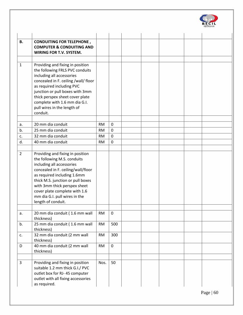
Page | 60
B. CONDUITING FOR TELEPHONE , COMPUTER & CONDUITING AND WIRING FOR T.V. SYSTEM.
1 Providing and fixing in position the following FRLS PVC conduits including all accessories concealed in F. ceiling /wall/ floor as required including PVC junction or pull boxes with 3mm thick perspex sheet cover plate complete with 1.6 mm dia G.I. pull wires in the length of conduit.
a. 20 mm dia conduit RM 0
b. 25 mm dia conduit RM 0
c. 32 mm dia conduit RM 0
d. 40 mm dia conduit RM 0
2 Providing and fixing in position the following M.S. conduits including all accessories concealed in F. ceiling/wall/floor as required including 1.6mm thick M.S. junction or pull boxes with 3mm thick perspex sheet cover plate complete with 1.6 mm dia G.I. pull wires in the length of conduit.
a. 20 mm dia conduit ( 1.6 mm wall thickness)
RM 0
b. 25 mm dia conduit ( 1.6 mm wall thickness)
RM 500
c. 32 mm dia conduit (2 mm wall thickness)
RM 300
D 40 mm dia conduit (2 mm wall thickness)
RM 0
3 Providing and fixing in position suitable 1.2 mm thick G.I./ PVC outlet box for RJ- 45 computer outlet with all fixing accessories as required.
Nos. 50

Page | 61
4 Supply and fixing of 1.2 mm thick G.I Box along with RG 11 TV Co axial socket with Cover Plate
Nos. 27
5 Supply drawing connecting testing and commissioning of TV Coaxial cable RG 6 in existing conduit
RM 1100
TOTAL CARRIED OVER TO SUMMARY
C. EARTHING SYSTEM
1 Providing and fixing in position the following copper strips and wires including providing all fixing accessories and effecting proper connections (MAKE - UNIEARTH)
a. G.I. tape 25 mm x 6 mm RM 250
b. Copper tape 25mm x 3 mm RM 60
c. GI wire 8 SWG RM 2000
d. Copper wire 8 SWG RM 75
e. Bimetallic conductor Nos. 6
2 Supply and laying, effecting proper connections, testing & commissioning of the following sizes of 1.1 KV armoured XLPE/ unarmoured Cross linked polyethylene insulated, PVC sheathed (XLPE), conforming to IS: 7098 (Part-1)- 1988 ( 90 deg C) aluminium /copper conductor cables conforming to IS : 1554 and IS 694 for Flexible copper cable Part I - 1976 with latest amendments laid over MS supports in existing RCC ducts/ laid in ground /laid on Cable Trays including clamping the cables to supports in an approved manner as required

Page | 62
complete with all accessories.All cables shall have thermo setting insulation XLPE and low emission of smoke and corrosive gas when affected by fire.
a. 1c x 70 sq.mm FR PVC insulated flexible copper conductor cables (For UPS Earthing )
RM 400
b. 1c x 35 sq.mm FR PVC insulated flexible copper conductor cables (For UPS Earthing & Server )
RM 800
c. 1c x 25 sq.mm FR PVC insulated flexible copper conductor cables
RM 200
d. 1c x 16 sq.mm FR PVC insulated flexible copper conductor cables.
RM 225
E 1 x 10 Sq. mm FR PVC insulated flexible copper conductor cables (Green Colour for Server Rack Earthing)
RM 250
F 2 Nos 1 x 10 Sq. mm FR PVC insulated flexible copper conductor cables (Green Colour for UPS DB Sub-main Earthing)
RM 150
G 1 x 6 Sq. mm FR PVC insulated flexible copper conductor cables (Green Colour)
RM 300
3 Supplying and making terminal joints for the following size of compression lugs and PG Threaded Nylon Flexible cable glands complete with all fixing accessories as required
a. 1c x 70 sq.mm FR PVC insulated flexible copper conductor cables (For UPS Earthing )
Jt 6

Page | 63
b. 1c x 35 sq.mm FR PVC insulated flexible copper conductor cables
Jt 10
c. 1c x 25 sq.mm FR PVC insulated flexible copper conductor cables
Jt 8
d. 1c x 16 sq.mm FR PVC insulated flexible copper conductor cables.
Jt 10
E 1 x 10 Sq. mm FR PVC insulated flexible copper conductor cables (Green Colour for Server Rack Earthing)
Jt 4
4 Providing earthing station at location as called for including providing 600 mm x 600 mm x 3 mm thick tinned copper electrode 2 Nos 25 x 3 mm copper strip (for body earthing GI strip can be considerd) up to ground level 20mm dia medium class GI pipe (India Tube Company make or approved equal) CI funnel with 20 gauge GI wire mesh, masonry chamber with concrete base, CI manhole cover (cover to be heavy duty) with frame (300mm x 300mm) and bitumastic paint and packing the fixture of charcoal and common salt around plate electrode complete as per I.S. ( Minimum depth shall be 4.2 M ) (Body earthing for Panels)
Nos. 0

Page | 64
5 Supply, Installation, testing and commissioning of Maintenance Free Earthing of make Electrolytic Earthing comprising of type 'K' copper 2.4 mm wall thickness, hollow tube 10 feet long, 2.125 inches outer diameter completely filled with non hazardous metallic salts (Terrafill) to achieve an earth resistance of less than 1 ohms. Provide masonry chamber with concrete base, CI manhole cover (cover to be heavy duty) with frame (300mm x 300mm) and make earth pit sign/ identifcation no in each earth station for UPS & Server
Nos. 6
6 Supply, installation, testing and commissioning of sheet metal enclosed 400 x 300 x 200 ( D) mm insulated earth distribution board with 1 nos. 50 x 6 mm copper tinned earth bars suitable for 10/12 nos connections complete with all fixing accessories as required.It shall have a clear glass viewing panel in the front of the panel.
Nos. 0
7 Supply, installation, testing and commissioning of sheet metal enclosed 300 x 200 x 150 ( D) mm insulated earth distribution board with 1 nos. 50 x 6 mm copper tinned earth bars on SMC insulator suitable for 6/8 nos connections complete with all fixing accessories as required.
Nos. 5
8 Supplying and laying of the following sizes of Heavy duty PVC Pipes below paved area including chase cutting and back filling.
a. 100 mm outer dia RM 50
b. 80 mm outer dia RM 0

Page | 65
TOTAL CARRIED OVER TO SUMMARY
D CABLES ,MAINS & SUBMAINS
1 Supply and laying, effecting proper connections, testing & commissioning of the following sizes of 1.1 KV armoured XLPE / unarmoured Cross linked polyethylene insulated, PVC sheathed (XLPE), conforming to IS: 7098 (Part-1)- 1988 ( 90 deg C) aluminium /copper conductor cables conforming to IS : 1554 and IS 694 for Flexible copper cable Part I - 1976 with latest amendments laid over MS supports in existing RCC ducts/ laid in ground /laid on Cable Trays including clamping the cables to supports in an approved manner as required complete with all accessories.All cables shall have thermo setting insulation XLPE and low emission of smoke and corrosive gas when affected by fire
Note : All cables to be glanded and crimped with suitable sized lugs. All Cable trays to be double earthed. All raceways and cable glands to be earthed with brass round earth clips and wires.
A 3.5 c x 240 sq.mm armoured XLPE insulated aluminium conductor cable
RM 100
B 3.5 c x 185 sq.mm armoured XLPE insulated aluminium conductor cable
RM 100

Page | 66
C 3.5 c x 150 sq.mm armoured XLPE insulated aluminium conductor cable
RM 0
D 3.5 c x 95 sq.mm armoured XLPE insulated aluminium conductor cable
RM 0
E 3.5 c x 70 sq.mm armoured XLPE insulated aluminium conductor cable
RM 150
F 4 c x 50 sq.mm armoured XLPE insulated aluminium conductor cable
RM 80
G 4 c x 35 sq.mm armoured XLPE insulated copper conductor cable
RM 0
H 4 c x 25 sq.mm armoured XLPE insulated aluminium conductor cable
RM 0
I 4 c x 10 sq.mm armoured XLPE insulated copper cable
RM 0
J 4 c x 16 sq.mm armoured XLPE insulated copper cable for Light and power & UPS DB's
RM 1250
K 4 c x 16 sq.mm armoured XLPE insulated aluminium cable
RM 300
L 4 c x 10 sq.mm armoured XLPE insulated aluminium cable
RM 250
M 4 c x 6 sq.mm armoured XLPE insulated aluminium cable
RM 900
N 3 c x 4 sq.mm armoured XLPE insulated copper conductor cable
RM 3000
O 2 c x 16 sq.mm armoured XLPE insulated copper conductor cables
RM 200

Page | 67
P 2 c x 10sq.mm armoured XLPE insulated copper conductor cables
RM 100
Q 1c x 10 sq.mm FR PVC insulated flexible copper conductor cables
RM 25
R 1c x 25 sq.mm FR PVC insulated flexible copper conductor cables
RM 1500
S 1c x 35 sq.mm FR PVC insulated flexible copper conductor cables
RM 350
T 1c x 50 sq.mm FR PVC insulated flexible copper conductor cables
RM 350
2 Supplying and making terminal joints for the following size of 1.1 KV PVC insulated copper conductor armoured cables including providing heavy duty copper terminal crimping lugs, solder, insulation tape, approved sealing epoxy compound, double compression brass cable glands, effecting gland connections and effecting terminal connections to the equipment complete as required. Use compression lugs and PG Threaded Nylon Flexible cable glands for single core flexible cables
A 3.5 c x 240 sq.mm armoured XLPE insulated aluminium conductor cable
Jt 4
B 3.5 c x 185 sq.mm armoured XLPE insulated aluminium conductor cable
Jt 4
C 3.5 c x 150 sq.mm armoured XLPE insulated aluminium conductor cable
Jt 0

Page | 68
D 3.5 c x 95 sq.mm armoured XLPE insulated aluminium conductor cable
Jt 0
E 3.5 c x 70 sq.mm armoured XLPE insulated aluminium conductor cable
Jt 8
F 4 c x 50 sq.mm armoured XLPE insulated aluminium conductor cable
Jt 4
G 4 c x 35 sq.mm armoured XLPE insulated copper conductor cable
Jt 0
h 4 c x 25 sq.mm armoured XLPE insulated aluminium conductor cable
Jt 0
I 4 c x 10 sq.mm armoured XLPE insulated copper cable
Jt 0
J 4 c x 16 sq.mm armoured XLPE insulated copper cable for Light and power & UPS DB's
Jt 38
K 4 c x 16 sq.mm armoured XLPE insulated aluminium cable
Jt 10
L 4 c x 10 sq.mm armoured XLPE insulated aluminium cable
Jt 8
M 4 c x 6 sq.mm armoured XLPE insulated aluminium cable
Jt 26
N 3 c x 4 sq.mm armoured XLPE insulated copper conductor cable
Jt 100
O 2 c x 16 sq.mm armoured XLPE insulated copper conductor cables
Jt 4
P 2 c x 10sq.mm armoured XLPE insulated copper conductor cables
Jt 4

Page | 69
Q 1c x 16 sq.mm FR PVC insulated flexible copper conductor cables
Jt 4
R 1c x 25 sq.mm FR PVC insulated flexible copper conductor cables
Jt 32
S 1c x 35 sq.mm FR PVC insulated flexible copper conductor cables
Jt 32
T 1c x 50 sq.mm FR PVC insulated flexible copper conductor cables
Jt 32
TOTAL CARRIED OVER TO SUMMARY
E RACEWAYS AND CABLE TRAYS
1 Fabricating supplying to site of installation, installation on ceiling/ surface 1.6 mm thick M.S. powder coated raceways of height 50 mm and 2.0 mm thick openable cover, totally enclosed, the joints between two lengths of channels or between channel and junction box shall be joined together with 3 mm thick M.S. Powder coated coupler plates to make it dust and water proof. The cost shall including all supporting and fixing accessories including dash fasteners.
A 250 mm (wide) x 50 mm (height) RM 250
B 150 mm (wide) x 50 mm (height) RM 275
C 100 mm (wide) x 50 mm (height) RM 100
D 150 mm (wide) x 150 mm (height)
RM 0

Page | 70
2 Fabricating supplying to site of installation, in floor including chase cutting of floor,leveling, refilling and making good the same from 1.6 mm thick and 2 mm thick cover M.S. powder coated, totally enclosed, height 40 mm . The two lengths of raceways shall be fitted with Collars , 50 mm wide, 3 mm thick , press fit type. The raceways shall be clamped to the floor slab with M.S. clamps , 3mm thick and shall be screwed to the floor slab. The joint between raceway and junction box will be made with GI flexible strip( 3 nos), 3 mm thick, 4 inches long ,15 mm wide which will be nut bolted to the Junction box complete as required etc.
A 250 mm (wide) x 40 mm (height) RM 250
B 150 mm (wide) x40 mm (height) RM 180
C 100 mm (wide) x 40 mm (height) RM 125
3 Fabricating supplying to site of installation, Junction boxes for Floor and Ceiling raceways made from 2 mm thick , with 2.5 mm thick M.S. powder coated cover including providing neoprene gaskets between the cover and the junction box, cadmium plated flat/round head screws, height as per site condition,totally enclosed. Proper cutouts shall be made in the side walls for raceway entry wherever required. The junction box shall be all side walls should be welded expect top cover and all side walls shall have suitable size of rectangular knock out holes for taking raceways / conduits as required and not a complete cut out. The top cover should be sealed with M Seal to make it

Page | 71
dust and water proof complete as required etc.
(variation in height may be considered for quoting as floor thickness may vary)
a. 350 mm x 350 x 60 mm (height) Nos. 0
B 300 mm x 300 x 60 mm (height) Nos. 130
C 200 mm x 200 x 60 mm (height) Nos. 90
d. 150 mm x 150 x 60 mm (height) Nos. 80
e. 100 mm x 100 x 60 mm (height) Nos. 0
4 Design manufacture , supply and fixing in position the cable trays of the following sizes for supporting 1.1 KV grade armoured/unarmoured aluminium /copper conductor cables. Fabricate the cable trays from perforated 1.6/2mm thick M.S. CRCA sheet duly galvanised with expansion coupler plates duly galvanised, with bolts, washer and nuts. Knock out holes for cable connections as per approved design. The tray should comply with the specification of NEC (National Electric Codes) and NEMA (National Electric Manufacturers Association). The steel should be as per IS:226 and galvanising as per IS :2629/BS 729/ASTM 123. The rate shall also include for supporting steel , fish plates , fixing accessories , nuts bolts, supporting down rods , dash fastener, cutting the RCC etc. complete as required. (the horizontal and vertical bends, T's should be factory fabricated and the rate should include for the same)
a. 150 mm wide x 40 mm x 1.6 mm thk
RM 125
b. 300 mm wide x 40 mm x 2.0 mm thk
RM 75

Page | 72
c. 450 mm wide x 40 mm x 2.0 mm thk
RM 80
d. 600 mm wide x 40 mm x 2.0 mm thk
RM 25
5 Fabricating ,supplying to site of installation, installation of following size of 450 mm wide and 105 mm height mesh type EZ -Electroplated Zinc ( Legrand -Cablofil make) cable tray including threaded G.I. down rods, dash fasteners,cablofil fixing accesories etc. complete as required.Cablofil make
RM 50
TOTAL CARRIED OVER TO SUMMARY
F DISTRIBUTION BOARDS
1 Supply,inginstalling,connecting testing and commissioning of the following double door 1/4 rows vertical type 1.6 mm thick and 1. 4 thick door sheet steel enclosed fully recessed type, TPN Miniature Circuit Breakers Distribution Boards dust proof, vermin proof, with hinged and lockable doors complete with DP MCB's and inter-connection with copper wire , insulated copper bus bar , cable glands/conduit entry bushes, bonding to earth and painting. Also provide separate neutral busbar for each phase. Provide separate Earth Links for each phase. Use brass thimbles for connections of all wires. 1 row for single phase and 4 rows for 3 phase. Provide separate 4 way 63 A main neutral link also. The phase busbar links shall be factory pre insulated.
1 Light & Power Distribution

Page | 73
Board
A 8 Way TPN DB, each phase consisting of 6 Nos. 10/20 AMP SP MCB’s and controlled by one number 100 mA sensitivity 40 AMPS DP RCCB backed up with 1 no 40 Amps 4 pole MCB. (Café DB)
Nos..
1
B 10 Way TPN DB, each phase consisting of 8 Nos. 10/20 AMP SP MCB’s and controlled by one number 100 mA sensitivity 63 AMPS DP RCCB backed up with 1 no 63 Amps 4 pole MCB.(Light DB)
Nos..
4
C 12 Way TPN DB, each phase consisting of 10 Nos. 10/20 AMP SP MCB’s and controlled by one number 100 mA sensitivity 63 AMPS DP RCCB backed up with 1 no 63 Amps 4 pole MCB.(Power DB)
Nos..
4
d. 10 Way SPN DB, consisting of 8 Nos. 10/20 AMP SP MCB’s and controlled by one number 100 mA sensitivity 40 AMPS DP RCCB backed up with 40 Amps DP MCB.For emergency Light
Nos..
2
2 UPS Distribution Boards (All MCB's in UPS DB's should be D Curve)
a. 8 Way TPN DB, each phase consisting of 6 Nos. 10/20 AMP SP MCB’s and controlled by one number 100 mA sensitivity40 AMPS DP RCCB for each phase and 1 no. 40 amps 4 pole MCB incomer
Nos..
0

Page | 74
b. 10 Way TPN DB, each phase consisting of 8 Nos. 10/20 AMP SP MCB’s and controlled by one number 100 mA sensitivity 63 AMPS DP RCCB for each phase and 1 no. 63 amps 4 pole MCB incomer
Nos..
0
c. 14 Way TPN DB, each phase consisting of 12 Nos. 10/20 AMP SP MCB’s and controlled by one number 100 mA sensitivity 63 AMPS DP RCCB for each phase and 1 no. 63 amps 4 pole MCB incomer (UPS DB)
Nos..
4
d. 16 Way SPN DB, consisting of 6 Nos. 20/32 AMP DP MCB’s and controlled by one number 30 mA sensitivity 63 AMPS DP RCCB backed up with 63 Amps DP MCB. The bus bar shall be Twin bus bar (For Hub DB Room)
Nos..
2
3 Supply, installation, testing and commissioning of sheet metal enclosed 125 Amps 4 pole manual change over switch with 125 A TPN MCCB (25 KA) for & 60 KVA UPS This shall include cable entry boxes both for incoming and outgoing cable)
Nos. 2
4 Supply, installation, testing and commissioning of sheet metal enclosed 100 A TPN MCCB ( 25 KA) for 40 KVA UPS This shall include cable entry boxes both for incoming and outgoing cable)
Nos. 2
5 Supply, installation, testing and commissioning of sheet metal enclosed 63 A TPN MCCB ( 25 KA) for PAC This shall include cable entry boxes both for incoming and outgoing cable)
Nos. 7

Page | 75
6 Supply, installation, testing and commissioning of sheet metal enclosed 63 A DP MCB ( 10 KA). This shall include cable entry boxes both for incoming and outgoing cable)
Nos. 2
7 Supply, installation, testing and commissioning of weather proof enclosures fitted with 63A TPN MCB for Ductable AC
Nos. 5
8 Supply, installation, testing and commissioning of weather proof polycarbonate enclosures fitted with 40/32 A TPN MCB for A.C.
Nos. 17
9 Supply, installation, testing and commissioning of weather proof polycarbonate enclosures fitted with 32 A DP MCB ( For Hi-wall Split)
Nos. 48
10 Supply, installation, testing and commissioning of sheet metal enclosure 40 A DP MCB This shall include cable entry boxes both for incoming and outgoing cable) for Inverter.
Nos. 0
11 Supply, installation, testing & commissioning of 5 KVA, Single Phase in put and single phase out put Pure Sine Wave inverter with 1.5 Hour Sealed Lead Acid Maintenance Free batteries back up complete with battery cabinet and as per specification
Nos. 1
TOTAL CARRIED OVER TO SUMMARY
G SUB DISTRIBUTION PANELS
1 Sub Distribution Panels

Page | 76
Design, manufacture, supplying & installing at site in positioning, connecting, testing and commissioning of the following cubical type, dead front, 2mm thick sheet steel enclosed, free standing indoor type extendible Sub Distribution Panel with vermin proof hinged lockable doors for each compartment provide bus bar interconnections for incoming and outgoing including feeders earthing and painting and as per specifications.
Note Provide insulated dedicated earth link in all UPS Panels
All MCCB's 250 Amps and above shall be Microprocessor based
All Light & Power panel ,UPS and A.C. Panel incomer MCCB shall have Over current, Earth fault and short circuit protection.
All MCB's in UPS Panels shall be D Curve
In all Electrical panels protective acrylic sheet to be provided in cable alley and feeders.
The meters shall be able to monitor all major power quality parameters Voltage , current , frequency , KVAH,KWH,Power factor and harmonics.
a The UPS Panel Worksation-( UPS Room) shall consists of :
MAIN INCOMER
2 Nos. 100 A TP+ 2N MCCB (25 kA) ( O/C, S/C ) and neutral isolation link 100% of rated current. Terminals suitable to receive cable connection on one side and Busbar connection on
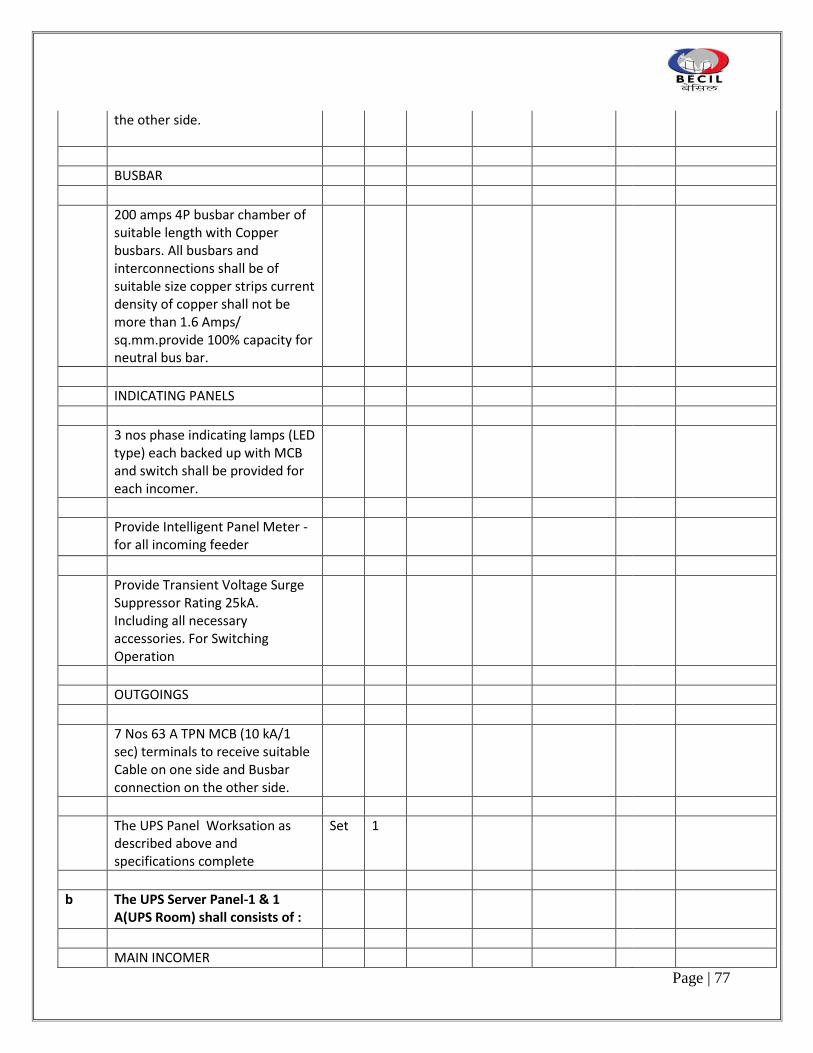
Page | 77
the other side.
BUSBAR
200 amps 4P busbar chamber of suitable length with Copper busbars. All busbars and interconnections shall be of suitable size copper strips current density of copper shall not be more than 1.6 Amps/ sq.mm.provide 100% capacity for neutral bus bar.
INDICATING PANELS
3 nos phase indicating lamps (LED type) each backed up with MCB and switch shall be provided for each incomer.
Provide Intelligent Panel Meter - for all incoming feeder
Provide Transient Voltage Surge Suppressor Rating 25kA. Including all necessary accessories. For Switching Operation
OUTGOINGS
7 Nos 63 A TPN MCB (10 kA/1 sec) terminals to receive suitable Cable on one side and Busbar connection on the other side.
The UPS Panel Worksation as described above and specifications complete
Set 1
b The UPS Server Panel-1 & 1 A(UPS Room) shall consists of :
MAIN INCOMER

Page | 78
1 No. 125 A TP+ 2N MCCB (25 kA) ( O/C, S/C ) and neutral isolation link 100% of rated current. Terminals suitable to receive cable connection on one side and Busbar connection on the other side.
BUSBAR
200 amps 4P busbar chamber of suitable length with Copper busbars. All busbars and interconnections shall be of suitable size copper strips current density of copper shall not be more than 1.6 Amps/ sq.mm.provide 100% capacity for neutral bus bar.
INDICATING PANELS
3 nos phase indicating lamps (LED type) each backed up with MCB and switch shall be provided for each incomer.
Provide Intelligent Panel Meter - for all incoming feeder
Provide Transient Voltage Surge Suppressor Rating 25kA. Including all necessary accessories. For Switching Operation
OUTGOINGS
3 Nos 100 A TPN MCCB (25 kA/1 sec) terminals to receive suitable Cable on one side and Busbar connection on the other side.
2 Nos 63 A DP MCB ( 10 kA/1 sec) terminals to receive suitable Cable on one side and Busbar connection on the other side.

Page | 79
The UPS Server Panel-1 & 1 A(UPS Room) as described above and specifications complete
Set 2
c The PDU 1, 1A ,2 and 2 A shall consists of :
MAIN INCOMER
1 Nos. 100A TPN MCCB (25 KA/1 sec) . Terminals suitable to receive cable connection on one side and Busbar connection on the other side.
BUSBAR
150 amps 4P busbar chamber of suitable length with Copper busbars. All busbars and interconnections shall be of suitable size copper strips current density of copper shall not be more than 1.6 Amps/ sq.mm. provide 100% capacity for neutral bus bar.
INDICATING PANEL
3 nos phase indicating lamps (LED type) each backed up with MCB and switch shall be provided for each incomer.
Provide Intelligent Panel Meter - Schneider EM 6400 with RS 485 port for all incoming feeder
OUTGOINGS
30 Nos 20/32 A DP MCB (10 kA/1 sec) terminals to receive suitable Copper Flexible Cable on one side and Busbar connection on the other side.

Page | 80
The PDU 1, 1 A, 2 & 2A as described above and specifications complete
Set 4
d The SDB Light & Power-1 & 2(Typical) shall consists of :
MAIN INCOMER
1 nos. 250 A TPN MCCB ( 25 kA) (O/c, S/c ) terminal suitable for XLPE Aluminium cable connection on one side and Busbar connection on the other side.
BUSBAR
300 amps 4P busbar chamber for main and sub panel of suitable length with Aluminium busbars. All busbars and interconnections shall be of suitable size aluminium strips current density of aluminium shall not be more than 0.8 Amps/ sq.mm provide 100% capacity for neutral bus bar.
INDICATING PANEL
3 Nos. phase indicating lamps for all incomer & sub incomer feeders, each backed up with MCB and switch shall be provided for incomer. and sub incomer
Provide Intelligent Panel Meter - dual source with RS 485 port for all incoming feeder
Provide on/Off indicating lamp on each incomer
OUTGOINGS

Page | 81
3 Nos. 125 A TPN MCCB terminals to receive suitable Cable connection on one side and Busbar connection on the other side.
2 Nos. 100 A TPN MCCB terminals to receive suitable Cable connection on one side and Busbar connection on the other side.
7 Nos. 63 A TPN MCB (10 kA) terminals to receive suitable Cable connection on one side and Busbar connection on the other side.
2 Nos. 63/40 A DP MCB (10 kA) terminals to receive suitable Cable connection on one side and Busbar connection on the other side.
SDB (L& P) -1 &2 as described above and specifications complete.
Set 2
e The AC Panel-1 & 2 shall consists of :
MAIN INCOMER
Main incomer 1 No. 250 A TPN MCCB ( 25 kA/ 1 sec) terminal suitable for cable connection on one side and Busbar connection on the other side.
BUSBAR
300 amps TPN busbar chamber of suitable length with Copper busbars. All busbars and interconnections shall be of suitable size copper strips current density of copper shall not be more than 1.6 Amps/ sq.mm

Page | 82
provide 50 % capacity for neutral bus bar.
INDICATING PANEL
3 nos phase indicating lamps each backed up with MCB and switch shall be provided for incomer.
Provide earth fault in the incomer
Provide Intelligent Panel Meter - Schneider EM 6436 Meter with RS 485 port for all incomming feeder
OUTGOINGS
5 Nos. 63 A TPN MCCB (25kA/1 sec) terminals to receive suitable Cable on one side and Busbar connection on the other side.
3 Nos. 63 A TPN MCB (10kA/1 sec) terminals to receive suitable Cable on one side and Busbar connection on the other side.
5 Nos. 40 A TPN MCB (10kA/1 sec) terminals to receive suitable Cable on one side and Busbar connection on the other side.
6 Nos. 32 A TPN MCB (10kA/1 sec) terminals to receive suitable Cable on one side and Busbar connection on the other side.
28 Nos. 32/25A DP MCB (10kA/1 sec) terminals to receive suitable Cable on one side and Busbar connection on the other side.

Page | 83
AC Panel-1 & 2 (Typical) as described above and specifications complete.
Set 2
2 The contractor to submit reports of torque tightness tests for all the nut bolt cable joints in all the panels with red marking after the torque tightening has been done as per manufactures recommendation.
L.S 1
3 Thermal scanning of all the cable and wiring joints in all the panels and MCB Distribution Baords after commissioning .
LS 1
4 Providing & fixing in position 1000 mm wide , Electrical Insulating Mats as per IS 15652:2006, 2mm thick, suitable upto 3.3 KV , fire retardant,no effect of acids, alkalies and transformer oils, moisture proof, high tensile strength and texture finish / cloth impression (Anti slip , marking on top) .
RM 8
5 Supply & fixing in position approved shock treatment chart written in English, Hindi and Local language. These charts shall be framed in wooden frame & covered with clear glass.
Nos. 1
6 Supply & fixing in position the best quality danger notice boards of approved shape & size as reqd. by the local Electrical Inspecting Authority written in English, Hindi & local language.
Nos. 1
TOTAL CARRIED OVER TO SUMMARY

Page | 84
H SUPPLY & FIXING OF LIGHTING FIXTURES
1 Supplying ,fixing in position testing and commissioning of the following Lighting fixtures including lamps at site. Use all Elante Trulite/Osram lumilux plus Eco lamps in Fluorescent lamp fittings. Use Osram CFL lamp - Dulux L Lumilux in all CFL lamp fixtures (Samples of all light fixtures to be submitted to the client for approval prior to procurement of fixtures)
Note--
All Light Fixture shall be with H.F. electronic ballast (THD less than 10% and P.F. 0.995 )
Color code – 84 for workstation area and all enclosed spaces
All the light fixture shall be factory prewired with extension cable from the terminal within the fitting, 6 feet long
a 45 Watts Recessed LED luminaire 600 X 600 as per ELANTE cat. No. RC450B LED-25-6500 PSE OD WH or equivalent complete as required
Nos 220
b 15 W LED recessed downlight as per Elante Cat. No. BBS 170 IXDLED- 4000 PSU WH or equivalent complete as required
Nos 222
c 15 W LED recessed downlight as per Elante Cat. No. BBS 175 IXDLED- 4000 PSU WH or equivalent complete as required
Nos 115
d 1 X 6.5 Watt ,Recessed LED spot/directional light fixtures as per Elante Cat No. QBS027, or Equivalent make
Nos 53

Page | 85
18 W LED surface mounted downlighter as per Lighting Technologies Cat. No. L018 CTS 240V or equivalent complate as required
Nos 22
e Round Hanging decorative light fixture as per approved by Architects Basic cost of light fixture Rs 7000
Nos 3
f Suspended 1 x 28 LED watts 4' -0" channel light fixture Wipro LM 31
Nos 0
g 28 W 4 '-0" LED Recessed channel light fixture as per Elante Cat No. LM30 or equivalent complete as required
Nos 48
h Pendant Decorative light fixture as approved by Architects Basic cost of light fixture Rs 5000.
Nos 9
i LED Strip light with 6W/meter connected length complete with Driver (Cat. No. LED Flexi Strip LSL6W)
RM 165
j 3 Watts LED Ni Cd Battery backup up to 2 hrs emergency Exit light with Flamproof Tennoware Make or equivalent make . The sample shall be submitted before ordering.
Nos 15
2 Supply & installation of Passive infra-red presence detector for lighting control to set the parameters of all meeting rooms and cabin (ON/OFF selection of lights)( Lights switch OFF in steps of 1 minute)
Nos 0

Page | 86
3 Supply, installation, testing commissioning of recessed ceiling mounted photo cell switching units to provide ON/OFF switching of lighting in response to ambient light levels.
Nos 0
a Switches lighting OFF when sufficient daylight is present.
b Used as on ON/OFF daylight dependant switch or in series with a wall switch
c Lighting level adjustable up to 1500 lux approx.
TOTAL CARRIED OVER TO SUMMARY

Page | 87
SUPPLY
S.no Item Description Unit Qty Make/Model Rate Amount Taxes Total Amount Including
Taxes
1 Design, manufacture and supply of 40 KVA/36 KW UPS(Input - three phase and Output -three phase) unit as per specifications - ( Parallel operation )
Nos 2
2 Design, manufacture and supplying of set of sealed maintenance free Batteries for 40 KVA/36 KW UPS for 15 Minutes backup as per specifications.
Set 2
3 Design, manufacture and supply of 60 KVA/54 KW UPS(Input - three phase and Output -three phase) unit as per specifications - ( Stand alone operation )
Nos 2
4 Design, manufacture and supplying of set of sealed maintenance free Batteries for 60 KVA/54 KW UPS for 15 Minutes backup as per specifications.
Set 2
5 Supply and Installation of Enclosed Battery Cabinet made from MS sheet steel duly powdered coated, for 40 KVA, matching the UPS in colour and finish ,complete with enclosed battery breaker, front access only and front door with ventilation louvres,U/V shunt trip ,proper ventilation, all copper cable interconnections and complying to the following conditions :
Operating Environment -0 - 35 °C, Operating Relative Humidity-20 - 80%, Operating Elevation- 0- to 99.9 meters, Storage Temperature-10 - 40 °C, Storage Elevation- 0-9000 meters, Regulatory Approvals CE, ISO 14001, ISO 9001.
Set 2

Page | 88
The battery cabinets shall be fabricated from the following Panel fabricators - Neptune / SPC Electrotech / Tricolite
6 Supply and Installation of Enclosed Battery Cabinet made from MS sheet steel duly powdered coated, for 60 KVA, matching the UPS in colour and finish ,complete with enclosed battery breaker, front access only and front door with ventilation louvres,U/V shunt trip ,proper ventilation, all copper cable interconnections and complying to the following conditions :
Operating Environment -0 - 35 °C, Operating Relative Humidity-20 - 80%, Operating Elevation- 0- to 99.9 meters, Storage Temperature-10 - 40 °C, Storage Elevation- 0-9000 meters, Regulatory Approvals CE, ISO 14001, ISO 9001.
Set 2
The battery cabinets shall be fabricated from the following Panel fabricators - Neptune / SPC Electrotech / Tricolite
Total
Grand Total ( Supply & Installation)

Page | 89
INSTALLATION
Sno Item Description Unit Qty Make/Model
Rate Amount Taxes Total Amount
Including Taxes
Make:-Scheinder/Emerson
1 Receiving from Owner's stores, assembling, installing in position, connecting testing and commissioning of the following UPS and Batteries complete as required.
a 40 KVA/36 KW UPS units Nos. 2
b 60 KVA/54 KW UPS units Nos. 2
c Set of maintenance free Batteries for 40 KVA/36 KW UPS units for 15 minutes backup, complete with battery cabinets for Battery bank.
Set 2
d Set of maintenance free Batteries for 60 KVA/54 KW UPS unit for 15 minutes backup, complete with battery cabinets for Battery bank.
Set 2
2 Testing of the 40 KVA UPS on site (installed on the 11th floor): It shall include providing the necessary Load Bank (100% load)with proper fans and electrical protection ,all cabling (about 200 metres) and earthing as required.The testing will also be done for battery back up time on full load.All the parameters(V,I,Wh, vah, pf, THDi, THDv, efficiency etc.) readings shall be noted on a Power Analyser simultaneously both on input and output. Please note the Load bank shall be installed at ground level
LS 1

Page | 90
3 Testing of the 60 KVA UPS on site (installed on the 11th floor): It shall include providing the necessary Load Bank (100% load)with proper fans and electrical protection ,all cabling (about 200 metres) and earthing as required.The testing will also be done for battery back up time on full load.All the parameters(V,I,Wh, vah, pf, THDi, THDv, efficiency etc.) readings shall be noted on a Power Analyser simultaneously both on input and output. Please note the Load bank shall be installed at ground level
LS 1
4 Fabrication , supply and installation of suitable size of MS angle stand support / base frame work for UPS and batteries.
KG 750
Grand Total
5 AMC Charges for 2 x 40 KVA + 2 X 60 KVA UPS
a 3rd Year ( Only for batteries) Lump Sum
b 4th Year ( for both UPS and Batteries )
Lump Sum
c 5th Year ( for both UPS and Batteries )
Lump Sum

Page | 91
3. HVAC

Page | 92
S.NO
ITEM DESCRIPTION UNIT QTY Make/Model
Rate Amount Taxes Total Amount Including Taxes
1.0 EQUIPMENT
1.1 SPLIT UNITS
Supply , Installation , Testing and Commissioning of split units, each comprising of an outdoor and a single indoor unit as shown on the drawings and as per the specifications.Enclosures shall be factory fabricated and painted to a smooth finish . Oudoor unit shall consist of hermatically sealed/ semi-hermatic scroll/rotary compressors, air cooled condenser with fan. Indoor unit shall consist of fan section with dynamically balanced centrifugal fan/s driven by FHP/TEFC squirrel cage induction motor, multirows deep DX- copper cooling coil with aluminium fins, thermostatic expansion valve, synthetic fibre filters, insulated drain pan, safety controls, safety controls, thermostat all complete in a unit. The quoted price shall be inclusive of full charge of refrigerant gas, vibration isolation arrangement.
A. Three phase ductable split units with

Page | 93
Scroll compressor : MAKE- Mitsubishi/Daiken/Scheinder
a.
8.5TR nominal capacity, split unit with single ductable type indoor unit and factory fitted electrical arrangement & corded remote.
No
5
b.
5.5TR nominal capacity, split unit with single ductable type indoor unit and factory fitted electrical arrangement & corded remote.
No
4
c.
4.0TR nominal capacity, split unit with single ductable type indoor unit and factory fitted electrical arrangement & corded remote.
No
3
B.
Single phase non ductable split units with rotary compressor (Three Star Rating) :
Cassette Type Units (MAKE-Mitsubishi/Daiken/Scheinder)
a.
3.0TR nominal capacity, split unit with single cassette type indoor unit with cordless control.
No
10
b.
2TR nominal capacity, split unit with single Cassette type indoor unit and cordless control.
No
6
c.
1.5TR nominal capacity, split unit with single Cassette type indoor unit and cordless control.
No
-

Page | 94
Hi-wall Type Units ( MAKE-Mitsubishi/Daiken/Scheinder EXCEPT 2.5TR)
a. 2.5TR nominal capacity, split unit with single
Hi-wall type indoor unit and corded
control . No 5
b. 2TR nominal capacity, split unit with single
Hi-wall type indoor unit and corded control .
No 3
c. 2TR nominal capacity, split unit with single
Hi-wall type indoor unit and cordless control .
No 4
d. 1.5TR nominal capacity, split unit with single
Hi-wall type indoor unit and corded control .
No 9
e. 1.5TR nominal capacity, split unit with single
Hi-wall type indoor unit and cordless control .
No 12
f. 1.0TR nominal capacity, split unit with single
Hi-wall type indoor unit and corded control
No 2
g. 1.0TR nominal capacity, split unit with single
Hi-wall type indoor unit and corless control
No 10
1.2 REFRIGERANT PIPING

Page | 95
Supply, Installation,Testing & Commissioning of copper refrigerant piping complete with copper fittings & charge of regrigerant gas for the above split units. Piping associated with split units to be insulated with closed cell elastomeric insulation in tubing form as required. Piping shall be laid over duly painted slotted angle trays fixed with GI clamps.Quoted Price shall be inclusive of UV protection paint for all exposed pipes of approved make .Price shall be inclusive of copper power cabling from indoor to outdoor unit as required.
a.
Pair of hard drawn copper refrigerant piping for the above split units with scroll compressor.
RM
205
b. Pair of Soft refrigerant piping for non ductable
split units with rotary compressor.
RM 670
1.3 STABILISERS
Supply, Installation,Testing & Commissioning of automatic voltage stabilisers suitable for operation on 140-280 V incoming supply supply with time delay relay for single phase split units.

Page | 96
a. 4 KVA Capacity No -
b. 5 KVA Capacity No -
1.4 Supply, Installation, Testing and
Commissioning of PLC for Auto Sequencing
of Split units/packaged units with microprocessor
based controller along with enclosure/accessories
having facility for configuratuion of the same
as per requirement for sequenced Start/Stop
for following split units :
a. Five number split units including 1 standby.
Set 1
b. Three number split units including 1 standby.
Set 4
b. Two number split units including 1 standby.
Set 1
1.5 DRAIN PUMP
Supply, Installation,Testing & Commissioning of drain pump for Hi-wall split units complete with all accessories as required. Drain Pump shall be suitable for operation on 220+6 % volts 50 Hz,1phase AC power supply.
1.6 EXHAUST FANS
1.6.1
INLINE FANS

Page | 97
Supply, Installation, Testing & Commissioning of circular /rectangular inline fans for exhaust air complete with sheet metal casing, direct driven centrifugal fan, motor with proper protection and inspection door. Fan shall be suitable for operation on 220+6 % volts,50 Hz, 1phase AC power supply. Flanges to be provided on both sides to facilitate duct connections. Fan shall be installed as shown in the drawings and will be of following characteristics : All single phase inline fans shall be provided with factory fitted speed regulators. All Fans Should be complete with Plug Top & necessary power cable.
Fan Capacity S.P Area to
No. (Cfm) (mmWG) to be exhausted
IF-1 1200 10-12 Larger Ladies & Gents Toilets (Rectangular) -South Side
No
1
IF-2 325 10-12 Smaller Ladies & Gents Toilets -South Side
No
1
IF-3 175 10-12 Pantry-South
Side No 1
IF-4 450 10-12 Toilet & Wash adjoining Director Cabin
No
1
IF-5 200 10-12 Stationary Store-South Side
No 1
IF-6 350 10-12 Male Locker Room
No 1

Page | 98
IF-7 325 10-12 Female Locker Room
No 1
IF-8 300 10-12 Technical Store No 1
IF-9 1450 10-12 LT Panel Room (Rectangular)
No
1
IF-10 500 10-12 Gents Toilet-North Side
No 1
IF-11 600 10-12 Ladies Toilet-North Side
No 1
IF-12 675 10-12 Kitchen/Pantry No 1
IF-13 550 10-12 Kitchen/Pantry No 1
1.6.2
PROPELLER FANS
Supplying , Installaing , Testing and Commissioning of propeller fans for exhaust air as shown on drawings. Each fan shall be complete with permanent split capacitor,mounting plate and accessories like wire guard, bird screen and gravity louvers for weather protection as required. Fan selection, arrangement and electrical characteristics shall be as follows :
a. 375 mm dia 900 RPM fan, single phase.
No -
b. 300 mm dia 900 RPM fan, single phase.
No -
c. 225 mm dia 1400 RPM fan, single phase.
No -
1.7 MS FRAME FOR ODUs
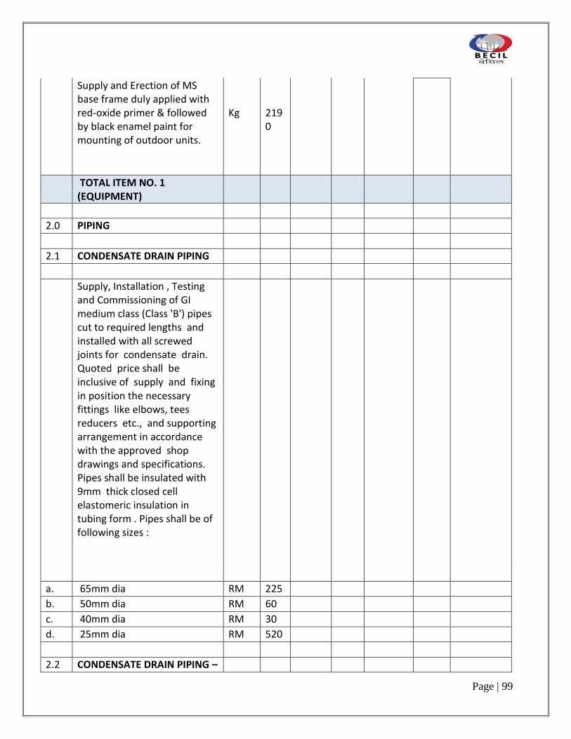
Page | 99
Supply and Erection of MS base frame duly applied with red-oxide primer & followed by black enamel paint for mounting of outdoor units.
Kg
2190
TOTAL ITEM NO. 1 (EQUIPMENT)
2.0 PIPING
2.1 CONDENSATE DRAIN PIPING
Supply, Installation , Testing and Commissioning of GI medium class (Class 'B') pipes cut to required lengths and installed with all screwed joints for condensate drain. Quoted price shall be inclusive of supply and fixing in position the necessary fittings like elbows, tees reducers etc., and supporting arrangement in accordance with the approved shop drawings and specifications. Pipes shall be insulated with 9mm thick closed cell elastomeric insulation in tubing form . Pipes shall be of following sizes :
a. 65mm dia RM 225
b. 50mm dia RM 60
c. 40mm dia RM 30
d. 25mm dia RM 520
2.2 CONDENSATE DRAIN PIPING –

Page | 100
cPVC
Supply, Installation , Testing and Commissioning of cPVC pipes cut to required lengths and installed for condensate drain. Quoted price shall be inclusive of supply and fixing in position the necessary fittings like elbows, tees reducers etc., and supporting arrangement in accordance with the approved shop drawings and specifications. Pipes shall be insulated with 9mm thick closed cell elastomeric insulation in tubing form. Pipes shall be of following sizes :
a. 65mm dia RM 2
b. 50mm dia RM 2
c. 40mm dia RM 2
d. 25mm dia RM 2
TOTAL ITEM NO. 2 (PIPING)
3.0 DUCTWORK/AIR TERMINALS
3.1 FACTORY FABRICATED DUCTING
Supply, Installation and Testing of factory fabricated GSS ducting complete with vanes,splitter dampers, fire retardant gaskets, hanging arrangement including fully threaded GI rods and GI "C" channels/ rolled steel wires or

Page | 101
Gripple Wire Rope Hangers & Supports complete with end fixing, GI "C" channels etc. as approved by clients/consultants in accordance with the approved shop drawings and specifications. Quoted price shall be inclusive of necessary scaffolding charges towards installation of supply/exhaust air ducts outside or within building wherever required.
Spacing between duct supports should not exceed 2m in both cases i.e GI rods with GI "C" channels & Gripple Wire Rope Hanger support . In case of Gripple Wire Rope Hanger support for duct sizes above 1800mm, MS angles duly painted with black enamel paint should be used along with neoprene pad in between the duct & MS angle.
While selecting the duct supports vendor shall ensure
vibration free installation.
a. 1mm to 899mm -- 26G GSS with TDC Joints
SqM 630
b. 900mm to 1200mm -- 24G GSS with TDC Joints
SqM 10
c. 1201mm to 1800mm - 22G GSS with TDC Joints
SqM 35
d. 1801mm to 2100mm - 20G GSS with TDC Joints
SqM 5
e. 2101mm to 2700mm - 18G GSS with TDC Joints
SqM -
3.2 SITE FABRICATED DUCTING

Page | 102
Supply, Fabrication, Installation and Testing of sheet metal ducts complete with vanes, splitter dampers, hanging arrangement including check nuts in accordance with the approved shop drawings and specifications:
a. 0.63mm (24 gauge) GSS SqM 20
b. 0.8 mm (22 gauge) GSS SqM 10
c. 1.0mm (20 gauge) GSS SqM 5
d. 1.25mm (18 gauge) GSS SqM -
3.3 FLEXIBLE CANVASS CONNECTIONS
Supply, Installation , Testing of 125mm deep antivibration flexible joints at the outlet of air handling units/inline fans. Flexible connections shall be constructed using imported fire retardant fabric with extruded aluminium frame/flange on both sides of approved make.
RM
40
3.4 LINEAR GRILLES

Page | 103
Supply, Installation , Testing and Balancing of one way blow linear supply cum return air grilles complete with removable/fixed core as per approved shop drawings and specifications.The grilles shall be of approved colour & shade. Powder coated aluminium grilles of extruded sections with integral flanges on both sides & ends as required complete with corner pieces.
i. 100/150/250 mm High grilles SqM 13
3.5 AIR TRANSFER GRILLES
Supply, Installation and Testing of extruded aluminium powder coated air transfer grilles to be provided at the door of toilets/pantry.
SqM
4
3.6 SUPPLY AIR DIFFUSERS

Page | 104
3.6.1
Supply, Installation, Testing and Balancing of square supply air & toilet exhaust air diffusers with removable key operated volume control dampers as per the approved shop drawings and specifications.The diffusers shall be anti-smudge ring type/flat type as approved by the interior designer. Powder coated extruded aluminium diffusers of approved colour & shade.
SqM
0.2
3.6.2
Supply, Installation, Testing and Balancing of square supply air diffusers with factory fitted removable key operated volume control dampers & 150mm high GSS plenum as per the approved shop drawings and specifications.The diffusers shall be anti-smudge ring /flat type. 600x600 Powder coated extruded aluminium diffusers of approved colour & shade suitable for fixing in grid ceiling.
No
46
3.7 RETURN AIR DIFFUSERS

Page | 105
3.7.1
Supply, Installation,Testing and Balancing of square return air diffusers same as supply air diffusers but without volume control dampers as per the approved shop drawings and specifications. The diffusers shall be anti -smudgering type. Powder coated extruded aluminium diffusers of approved colour & shade.
SqM
0.2
3.8.2
Supply, Installation,Testing and Balancing of square return air diffusers same as supply air diffusers but without volume control dampers as per the approved shop drawings and specifications. The diffusers shall be anti -smudgering /flat type. 600x600 Powder coated extruded aluminium diffusers of approved colour & shade suitable for fixing in gridceiling.
No
45
3.9
Supply, Installation, Testing and Balancing of lilear slot diffusers with Hit & Miss type extruded aluminium volume control dampers at supply air outlets as per the approved shop drawings and specifications.

Page | 106
a.
3 slot/2slot, powder coated extruded aluminium diffusers of approved colour & shade for supply air with Hit & Miss type dampers
SqM
-
b.
3 slot/2slot, powder coated extruded aluminium diffusers of approved colour & shade for return air without Hit & Miss type dampers
SqM
-
3.10
Supply, Installation,Testing and Balancing of flexible ducting comprising of inner as well as outer skin constructed out of aluminium & fibre glass insulation 25mm thick of minimum 24 kg/cu.m density insulation sandwitched in between. Duct should confir to fire rating standards BS-476 part 5, 6 & 7. Flexible Ducts of following sizes as per approved shop drawings, specifications :
a. 300 mm dia RM -
b. 250 mm dia RM 10
c. 200 mm dia RM 20
d. 150 mm dia RM 20
e. 100 mm dia RM -

Page | 107
3.11
Supply, Installation and Testing of single piece GI round spigot made out of spinning process with 50mm height and having grooves on both sides and circular flanges. Spigots shall be installed on main ducts to facilitate connection of flexible ducts.
a. 300 mm dia No -
b. 250 mm dia No 4
c. 200 mm dia No 10
d. 150 mm dia No 10
e. 100 mm dia No -
3.12
Supply, Installation and Testing of Butterfly damper of aluminium sheet construction with two flap with sleeve as per thespecifications and shop drawings.
a. 100 mm dia No -
b. 150 mm dia No 5
c. 200 mm dia No 5
d. 250 mm dia No 2
E. 300 mm dia No -
3.13
Supply, Installation and Testing of GI box type volume control dampers as per the specifications and shop drawings.
SqM
7
3.14
Supply, Installation and Testing of GI multi blade type louver dampers as per the specifications and shop drawings.
SqM
8.5

Page | 108
3.15
Supply, Installation and Testing of fresh air grilles of powder coated / anodised extruded aluminium with GI wire mesh, inlet louvers,Box type VCD & bird screen, as per the approved shop drawings and specifications.
SqM
0.5
3.16
Supply, Installation and Testing of extruded aluminium powder coated louver with GI wire mesh to be installed outside for discharge of exhaust air from exhaust fans as per the specifications and shop drawings. Sample of louvers to be got approved from consultants and Clients prior to procurement.
SqM
1.5
3.17
Supply, Installation and Testing of Bird Screens with GI wire mesh to be installed at the suction of fresh air/discharge of Exhaust air as per the specifications and shop drawings. Sample of bird screen to be got approved from consultants and Clients prior to procurement.
SqM
0.3
3.18
Supply, Installation and Testing of non return dampers.NRDs to be installed in the ducts as per the specifications and shop drawings.Sample of NRDs to be got approved from consultants and Clients prior to procurement.
SqM
1.5

Page | 109
TOTAL ITEM NO.3 (Ducting & Air Terminals)
4.0 INSULATION
4.1 ACOUSTIC LINING OF DUCTS
4.1.1
Using Open Cell Nitirile Rubber
Supply and Application of internal acoustic lining of supply air ducting using open cell nitrile rubber insulation with density within 140-180 Kg/m3 as per the approved shop drawings and specifications. Insulation material shall be bonded with the ducts using metal screw and washers to facilitate grip to the GI sheet.
a. 10mm thick lining SqM 20
4.1.2
Using Fibre Glass

Page | 110
Supply and Application of internal acoustic lining of supply/return air ducting using resin bonded fibre glass insulation of density not less than 32Kg/CuM as per the approved shop drawings and specifications. Quoted price shall be inclusive of GSS channel, metal screws, washers, fibre glass tissue, perforated sheet etc. as required for complete installation.
a. 25mm thick lining SqM 30
4.2 THERMAL INSULATION OF DUCTS
(Using Factory Laminated aluminium foil faced, Class 'O' Closed Cell Elastomeric insulation)
Supply and Application of external thermal insulation of supply /return air ducting using aluminium foil faced closed cell elastomeric insulation with class 'O' fire retardant properties as per the specifications and drawings. Foil shall provide protection from mechanical impact,ultra voilet radiations and Scratches etc. caldding shall not have any fibre erosion. Both insulation & foil should have built in antimicrobial protection.

Page | 111
a. 9mm thick insulation-S/Air duct in R/Air duct
SqM 600
b. 13mm thick insulation SqM 5
c. 16mm thick insulation SqM -
4.3
THERMAL INSULATION FOR GLAZING ABOVE FALSE CEILING (Using Closed Cell Elastomeric insulation)
Supply and Application of thermal insulation for glazing above false ceiling using closed cell elastomeric insulation having same specifications as above.
a. 16mm thick insulation SqM 2
4.4 Supply and Application of 16mm thick closed cell nitrile rubber elastomeric insulation for exposed roof towards underdeck insulation. Quoted price shall be inclusive of Pidilite SR-505/998 adhesive as required and as per the specifications.
SqM 1580
TOTAL ITEM NO. 4 (INSULATION)

Page | 112
3A. PAC

Page | 113
S. No. DESCRIPTION UNIT QTY
Make/Model
Rate Amount Taxes Total Amount Including Taxes
Make:-Scheinder/Emerson/Stulz
1. DOUBLE SKIN PRECISION PACKAGED UNITS
(With R-410A Refrigerant)
Supply, Installation, Testing and Commissioning of air cooled double skin precision type packaged air conditioning units, self contained floor discharge type complete with scroll compressor/s, fan section with statically & dynamically balanced centrifugal backward curved plug type fan driven by Electronically Commutated (EC) motor having true soft start characteristics (inrush current lower than operating current), multirows deep hydrophilic coated cooling coil with copper tubes and aluminium fins, remote aircooled condenser/s with copper tubes and aluminium fins and electronic expansion valve (EEV). Enclosure shall be in double skin construction (all sides to be double skin type) fabricated out of heavy gauge steel sheet & GI sheet of thickness not less than 1.2mm with minimum 25mm thick Fibre glass/mineral wool insulation sandwitched in between. Enclosure shall be supported on a fabricated steel structure. The unit shall be equipped with high efficiency synthetic fibre filters, SS drain pan duly insulated with 9mm thick Class "O" closed cell insulation, micro- processor based programmable logic controller, humidifier, multistage heaters,thermostat, water detection kit for water spillage under the flase

Page | 114
floor all complete in a unit as per the specifications. The enclosure shall be factory painted to a smooth finish. The precision unit shall also be complete with microprocessorbased electrical panel comprising of indication lights, Star-Delta/DOL starter, over load protection,necessary relay to be hooked up with fire & smoke detection system to facilitate auto trip of PAC andnecessary copper control wiring. The packaged units shall be complete with auto sequencing arrangement as required, power lossalarm, clogged filter alarm and shipped out of factory with full refrigerant charge. Each unit shall be provided with BMS integration card & master card to communicate all relevant data with BMS. (Applicable in the event BMS is there). The PAC units shall be suitable for operation on415+10% volts, 50 Hz three phase AC powersupply. Fan outlet velocity shall not exceed 300 MPM.Quoted price shall be inclusive of MS base frame duly painted with the black enamel paint for mounting of remote air cooled condensers and tubular MS base frame with adjustable legs duly painted for mounting of indoor unit..
PAC units shall be capable of maintaining desired Relative humidity in the Server Room even in the absence of full equipment load or with varying Equipment load. Heaters of PAC units shall automatically gets ON to maintain the set Relative humidity level in the Server Room. PAC Units shall be suitable to handle pressure drop associated with supply and return outlets as shown in the design drawing.Vendor shall study the said drawing & confirm

Page | 115
achievement of uniform inside conditions and air flow eliminating hot pockets. Vendors shall lsocalculate and confirm ESP based on the said drawings, however ESP of the units shall minimum be 80 Pa.
a. 5.5TR/3200Cfm actual capacity floor dischage type precision package units. One PAC unit shall remain as . standby. Actual capacity should be basedon 44C ambient temperature to achieve 20C inside temperature.Units shall be suitable to maintain 50% RH year round particularly during monsoon with the operation of heaters as may be required irespective of the eqipment load inside the Server Room.
No 4
b. 6.0TR/3600Cfm actual capacity floor dischage type precision package units. One PAC unit shall remain as . standby. Actual capacity should be based on 44C ambient temperature to achieve 20C inside temperature.Units shall be suitable to maintain 50% RH year round particularly during monsoon with the operation of heaters as may be required irespective of the eqipment load inside the Server Room.
No 4
Units shall be complete with factory fabricated double skin Return air plenums and motorized Damper. Plenum should have access for filters. Height of the plenum shall be as per approved drawing to touch the false ceiling for return airpick up. (Vendor to furnish rate separately)
No 4
Note : Vendor to furnish rate for BMS
integration card and master card separately.
No 4

Page | 116
2 REFRIGERANT PIPING Supply, Installation, testing &
Commissioning of hard drawn copper refregerant piping complete with fittings between indoor units and remote condensers. Refrigerant piping withinthe server room and above ceiling and in comfort AC areas shall be insulated with 13mm thick closed cell elastomeric insulation with class 'O' fire retardant properties in tubing form. Quoted price shall be inclusive of power cabling as required between indoor and outdoor units. Piping shall be supported properly in a neat & clean manner using GI clamps & slotted laddertype trays. a. Pair of hard drawn copper refrigerant piping not less than 16 gauge thick for Precision Packaged units having sinlge refrigerant circuits. b. Prepainted MS cover for refrigerant piping laid on 300 mm wide cable trays.
RM 160
RM 80
3 EXTENDED PIPING KIT (Required if separation between
indoor &outdoor unit exceeds 30RM) Supply, Installation, Testing and Commissioning of extended piping kitcomplete with check valves,solenoid valves,"U" trap,additional oil & refrigerant charge,cabling etc. as required.
Sets --
4 Supply, Installation, Testing and
Commissioning of following GI (Class 'B') drain piping for indoor units complete with

Page | 117
necessary elbows, tees, reducers etc. The pipe shall be insulated with 9mm thick closed cell elastomeric tubing insulation and secured with nitrile adhesive tape of matching colour & to be applied with necessary glass cloth and UV protection paint to achive smooth surface.. Pipes shall be of following sizes :
a. 50mm dia pipe RM 5
b. 40mm dia pipe RM 20
c. 25mm dia pipe RM 30
5 GI PIPING - For Humidifier Piping
Supply, Installation ,Testing and Commissioning of GI pipes (Class 'C') cut to required lengths and installed with all screwed joints for Humidifier soft water supply. Quoted price shall be inclusive of supply and fixing in position the necessary fittings like elbows, tees, reducers, sockets etc. and supporting arrangement in accordance with the approved shop drawings and specifications. All pipe supports shall be of Galvanised Steel. All sleeves in Fire wall/slab shall be sealed using fireproof sealant. Pipes shall be of following sizes :
Humidifier connections shall be done by low side vendor in close coordination with equipment manufacturer.
a. 50mm dia RM 5
b. 40mm dia RM 5
c. 25mm dia RM 10
d. 20mm dia RM 5
6 Supply, Installation , Testing and
Balancing of single louvered powder

Page | 118
coated extruded aluminium supply air grilles in accordance with the approved shop drawings and specifications. Grilles shall be provided with removable key- operated volume control dampers. Grilles shall be strong enough suitable for floor installation.
a. Powder coated extruded aluminiumgrilles of approved colour & shade. SqM 16
7 Supply, Installation ,Testing and Balancing of one way blow linear supply cum return air grilles complete with removable/fixed core as per approved shop drawings and specifications. The grilles shall be of approved colour & shade.
Powder coated aluminium grilles of extruded sections with integral flanges on both sides & ends as required complete with corner pieces.All grilles to be installed in ceiling to be properly supported from real slab using chains or gripple wires.
i. 100/150/250 mm High or 600x600 Square Grilles
SqM 14
(Sample of grilles shall be got approved from consultants/Owners prior to procurement).
8 THERMAL INSULATION
8.1 (Using Factory Laminated IC cladding
Class 'O' Closed Cell Elastomeric insulation)
Supply and Application of thermal insulation of ceiling & floor of Server

Page | 119
Room & walls below false floor and above ceiling using factory laminated IC cladding closed cell nitrile rubber elastomeric insulation with class 'O' fire retardant Properties as per the specifications and drawings. Black coloured IC cladding shall provide protection from mechanical impact, ultra voilet radiations and Scratches etc.caldding shall not have any fibre erosion. Both insulation & cladding should have built in antimicrobial protection. Quoted price shall be inclusive of Pidilite SR-998/505 adhesive as required and as per the specifications Using 16mm thick Using 19mm thick Supply and Application of 16mm thick thermal insulation of walls of Server Room using closed cell nitrile rubber elastomeric insulation with class 'O' fire retardant properties as per the specifications and drawings. Quoted price shall be inclusive of Pidilite SR-998/505 adhesive as required and as per the specifications (Vendor to repair all torn out insulation after installation of all services).
a. b.
SqM 285
SqM 5
8.2
SqM 235
9 Supply and Application of acoustic/ thermal lining of walls/ceiling of PAC rooms using resin bonded fibre glass insulation of density not less than 32Kg/CuM as per the approved shop

Page | 120
drawings and specifications. Quoted price shall be inclusive of GSS channel, metal screws, washers, fibre glass tissue, perforated sheet etc. as required for complete installation. 50mm thick
a. SqM --
10 Supply, Installation,Testing and Commissioning of motorised smoke cum fire dampers suitable for at least 90 minutes fire rating as per the specifications and approved shop drawings. Quoted price shall be inclusive of copper control wiring as required.
a. Bare Fire Dampers SqM --
b. Spring return action type actuator complete with
control panel and temperature sensor.
No --
11 COLD AISLE CONTAINMENT
Supply,Fabrication, Installation and Testing of cold aisle containment for Server Room. Cold Aisle Containment System should ensure effective and efficient supply of cold air from cold aisles and improve the cooling system efficiency. CAC should avoid any mixing of cold air with hot air. CAC shall be modular type. Structure & frame work should have sufficient strength, well finished. Containment material should not emit any hazardous emissions in the DC area. All components of the CAC shall have minimum 120 minutes fire rating.

Page | 121
a.
Cold aisle containment using 4mm thick Fire rated transparent Halogen free Plexiglass fixed in CRCA frame complete with support base assembly, dummy panels, bends, angular extusions & blanking panels 3U, 2U, 1U etc. Top panels shall have openings for smoke sensor/FM system wherever required. Top panel shall allow quick access to area above containment for maintenance activity. Contaiment shall be complete in all manners including controls and as per specifications.
SqM --
b.
CRCA Powder Coated steel sheet Sliding Doors (thickness not less than 1.2mm) on both sides with window arrangement complete with accessories and fittings
1200(w) x 2000(H) Doors as mentioned above
No --
600(w) x 2000(H) Doors as mentioned above
No --
12 FLOOR PRESSURISATION SYSTEM
Supply and Installtion of Automatic Floor Pressurisation System to ensure Constant pressure below raised Floor complete with Sensors etc. Pressurisation system shall be connected to PAC unit to vary the supply air quantity as per the requirement.
No --
TOTAL Rs.

Page | 122
4. MODULAR WORK

Page | 123
S.No. Particular Make/Model Qty. Rate Amount Taxes
Total Amount including
Taxes
In Nos.
Tables
1 Director Table L2100 x D900 x H750mm With Side Unit L2100 x D450 x H725mm Table top 25mm pre-lam particle board as per IS 14587 with 2mm pvc edge band. Bottom / verticle support 18mm pre-lam particle board with 0.8 pvc edge band. Side unit table top 25mm pre-lam particle board with 2mm pvc edge band. side unit with 2drawer & open shelf.Drawer front 18mm pre-lam particle board, In side 12mm pre-lam particle board with pvc edge band. Hardware Ebco or equivalent (MAKE- GODREJ/Featherlite/HNI)
1
2 Deputy Director Table L2100 x D900 x H750mm With Side Unit L900 x D400 x H750mm Table top 25mm pre-lam as per IS 14587 particle board with 2mm pvc edge band. Bottom / verticle support 18mm pre-lam particle board with 0.8 pvc edge band. Side unit table top 25mm pre-lam particle board with 2mm pvc edge band. side unit with 1drawer &1shutter & 1 open shelf.Drawer front 18mm pre-lam particle board, In side 12mm pre-lam particle board with pvc edge band. Hardware Ebco or equivalent (MAKE- GODREJ/ Featherlite/HNI)
3
3 Cubicle Table L1500 x D600 x H750mm With Side Unit L900 x D400 x H725mm Table top 25mm pre-lam particle board as pe IS 14587 with 2mm pvc edge band. Bottom / verticle support 18mm pre-lam particle board with 0.8 pvc edge band. Side unit table top 25mm pre-lam particle board with 2mm pvc edge band. side unit with 1drawer &1shutter & 1 open shelf.Drawer front 18mm pre-lam particle board, In side 12mm pre-lam particle board with pvc edge band. Hardware Ebco or equivalent (MAKE- GODREJ/ Featherlite/HNI)
7
4 Staff Members/CA Table L1200 x D600 x H750mm Table top 25mm pre-lam particle board as per IS 14587 with 2mm pvc edge band. Bottom / verticle support 18mm pre-lam particle board with 0.8 pvc edge band. Drawer & shutter front 18mm pre-lam particle board, In side 12mm pre-lam particle board with pvc edge band. Hardware Ebco or equivalent (MAKE- GODREJ/ Featherlite/HNI)
14

Page | 124
5 Guard Table L1650 x D600 x H750mm Table top 25mm pre-lam particle board with 2mm pvc edge band. Bottom / verticle support 18mm pre-lam particle board with 0.8 pvc edge band. Drawer & shutter front 18mm pre-lam particle board, In side 12mm pre-lam particle board with pvc edge band. Hardware Ebco or equivalent (MAKE- GODREJ/ Featherlite/HNI)
1
Providing and fixing 18 Seater Conference Table in prelam finish. Table top to be in 25mm thick prelam particle board supported with prelam modesty and gable end. (MAKE- GODREJ/ Featherlite/HNI)
1
6 60mm Aluminum Low Ht Partitions L1500 x H1200mm Partitions: 60mm aluminum anodised single trim modular partitions with provision for complete concealed wire management systems (cut outs only) The lover section of the partition up to the work top height 750mm covered with laminate on both sides. The partitions upper section above work top height 450mm will be provided magnetic pinup / writing board. Hardware Ebco or equivalent (MAKE- GODREJ/ Featherlite/HNI)
7
7 60mm Aluminum Partitions L1350 x H1200mm Partition: 60mm aluminum anodised single trim modular partitions with provision for complete concealed wire management systems (cut outs only) The lover section of the partition up to the work top height 750mm covered with laminate on both sides. The partitions upper section above work top height 450mm will be provided magnetic pinup / writing board. Hardware Ebco or equivalent (MAKE- GODREJ/ Featherlite/HNI)
1
8 60mm Aluminum Partitions L1090 x H1200mm Partition: 60mm aluminum anodised single trim modular partitions with provision for complete concealed wire management systems (cut outs only) The lover section of the partition up to the work top height 750mm covered with laminate on both sides. The partitions upper section above work top height 450mm will be provided magnetic pinup / writing board. Hardware Ebco or equivalent (MAKE- GODREJ/ Featherlite/HNI)
1

Page | 125
9 60mm Aluminum Partitions L1150 x H1200mm Partition: 60mm aluminum anodised single trim modular partitions with provision for complete concealed wire management systems (cut outs only) The lower section of the partition up to the work top height 750mm covered with laminate on both sides. The partitions upper section above work top height 450mm will be provided magnetic pinup / writing board. Hardware Ebco or equivalent (MAKE- GODREJ/ Featherlite/HNI)
2
10 60mm Aluminum Partitions L1100 x H1200mm Partition: 60mm aluminum anodised single trim modular partitions with provision for complete concealed wire management systems (cut outs only) The lower section of the partition up to the work top height 750mm covered with laminate on both sides. The partitions upper section above work top height 450mm will be provided magnetic pinup / writing board. Hardware Ebco or equivalent (MAKE- GODREJ/ Featherlite/HNI)
2
11 Pole Connector 1
Workstations
12 60mm Aluminum Workstations (Both Side Sharing) Size:- L4200 x D1260,960 x H1200mm (w/o side panel) Table top: 25mm pre-lam particle board as per IS 14587 with 2mm pvc edge band Gable end: 18mm pre-lam particle board with 0.8mm pvc edge band Partitions: 60mm aluminum anodised single trim modular partitions with provision for complete concealed wire management systems (cut outs only) The lower section of the partition up to the work top height 750mm covered with laminate on both sides. The partitions upper section above work top height 450mm will be provided magnetic pinup / writing board. Hardware Ebco or equivalent (MAKE- GODREJ/ Featherlite/HNI)
168
13 3Drawer Pedestal (Mobile with castor) Size:- L400xD450xH675mm Drawer front in 18mm pre-lam particle board asper IS 14587, In side 12mm pre-lam particle board with pvc edge band. Hardware Ebco or equivalent (MAKE- GODREJ/ Featherlite/HNI)
168
14 Key Board Tray in 18mm pre-lam particle board as per IS 14587 with pvc edge band. Hardware Ebco or equivalent (MAKE- GODREJ/ Featherlite/HNI)
168

Page | 126
15 Back Storage L1200 x D400 x H750mm Storages - Side,back & front In 18mm pre-lam particle board as per IS 14587 with 0.8mm pvc edge band. Hardware Ebco or equivalent ((MAKE- GODREJ/ Featherlite/HNI)
13
16 Back Storage L900 x D400 x H750mm Storages - Side,back & front In 18mm pre-lam particle board as per IS 14587 with 0.8mm pvc edge band.Hardware Ebco or equivalent (MAKE- GODREJ/ Featherlite/HNI)
1
17 Back Storage L800 x D400 x H750mm Storages - Side,back & front In 18mm pre-lam particle board as per IS 14587 with 0.8mm pvc edge band. Hardware Ebco or equivalent (MAKE- GODREJ/ Featherlite/HNI)
6
18 Storage L1140 x D400 x H1200mm Storages - Side, back & front In 18mm pre-lam particle board as per IS 14587 with 0.8mm pvc edge band.Hardware Ebco or equivalent (MAKE- GODREJ/ Featherlite/HNI)
2
19 Back Storage L1100 x D400 x H2400mm Storages - Side,back & front In 18mm pre-lam particle board as per IS 14587 with 0.8mm pvc edge band.Hardware Ebco or equivalent (MAKE- GODREJ/ Featherlite/HNI)
9
20 Storage L1200 x D400 x H1200mm Storages - Side,back & front In 18mm pre-lam particle board as per IS 14587 with 0.8mm pvc edge band.Hardware Ebco or equivalent (MAKE- GODREJ/ Featherlite/HNI)
15
21 Storage L750 x D400 x H1200mm Storages - Side,back & front In 18mm pre-lam particle board as per IS 14587 with 0.8mm pvc edge band.Hardware Ebco or equivalent (MAKE- GODREJ/ Featherlite/HNI)
5
22 Storage L900 x D400 x H2400mm Storages - Side,back & front In 18mm pre-lam particle board as per IS 14587 with 0.8mm pvc edge band.Hardware Ebco or equivalent (MAKE- GODREJ/ Featherlite/HNI)
7
23 Storage L900 x D600 x H2400mm Storages - Side,back & front In 18mm pre-lam particle board with 0.8mm pvc edge band.Hardware Ebco or equivalent (MAKE- GODREJ/ Featherlite/HNI)
4
Chairs & Sofas
24 Director Chair High Back Mettalic PP Arms,Metalic Base with Castor, Tilting Mechanism,Hydraulic Systems,Leathrite Upholstry (MAKE- GODREJ/ Featherlite/HNI)
1

Page | 127
25 Director Visitor Chairs Medium Back Metalic PP Arms,Mettalic Base with Castor, Tilting Mechanism,Hydraulic Systems,Leathrite Upholstry. (MAKE- GODREJ/ Featherlite/HNI)
3
26 Director Cabin Sofa (2 Seater) Wooden Frame with leathrite upholstry.(MAKE- GODREJ/ Featherlite/HNI)
2
27 Director Cabin Sofa (1 Seater) Wooden Frame with leathrite upholstry.(MAKE- GODREJ/ Featherlite/HNI)
1
28 Centre Table In SS With Glass Top 1200x600xH450mm (MAKE- GODREJ/ Featherlite/HNI)
5
29 Side Table In SS With Glass Top 450x450xH450mm (MAKE- GODREJ/ Featherlite/HNI)
9
30 Deputy Director Chairs High Back PP Arms,nylon base with castor,hydraulic systems,PP seat & back cover,PU foam,push back Mechanism, Seat leathrite & back net upholstry (MAKE- GODREJ/ Featherlite/HNI)
3
31 Deputy Director Visitor Chairs Medium Back PP Arms,nylon base with castor,hydraulic systems,PP seat & back cover,PU foam,push back Mechanism, Seat leathrite & back net upholstry (MAKE- GODREJ/ Featherlite/HNI)
9
32 Duputy Director Cabin & Vistor lounge Sofa (2 Seater) Wooden Frame with leathrite upholstry. (MAKE- GODREJ/ Featherlite/HNI)
4
32 Vistor lounge Sofa (3 Seater) Wooden Frame with leathrite upholstry. (MAKE- GODREJ/ Featherlite/HNI)
1
33 Sofa (4 Seater) PU Moulded Seat & Back with Leathrite Upholstry, SS Legs (MAKE- GODREJ/ Featherlite/HNI)
2
33 Sofa (2 Seater) PU Moulded Seat & Back with Leathrite Upholstry, SS Legs (MAKE- GODREJ/ Featherlite/HNI)
2
35 Cubicle Chair Medium Back PP Arms,nylon base with castor,hydraulic systems,PP seat & back cover,PU foam,push back Mechanism, Seat leathrite & back net upholstry (MAKE- GODREJ/ Featherlite/HNI)
6
36 Cubicle Visitor / CA / Workstations / Conference Chairs PP Arms,nylon base with castor,hydraulic systems,PP seat & back cover,PU foam,push back Mechanism, Seat leathrite & back net upholstry (MAKE- GODREJ/ Featherlite/HNI)
211
37 Sofa (2 Seater) PU Moulded Seat & Back with Leathrite Upholstry, SS Legs (MAKE- GODREJ/ Featherlite/HNI)
1

Page | 128
37 Sofa (2 Seater) PU Moulded Seat & Back with Leathrite Upholstry, SS Legs (MAKE- GODREJ/ Featherlite/HNI)
1
38 LOUNGE CHAIR: Provide and Install lounge chairs. (MAKE- GODREJ/ Featherlite/HNI)
10
39 Auditorium Chair, Push Back, PU Foam, PU Arm With Cup, Holder, Fire Retardant Fabric Tapestry (MAKE- GODREJ/ Featherlite/HNI)
75
40 Auditorium Sofa (4 Seater) (MAKE- GODREJ/ Featherlite/HNI)
2
41 Auditorium Sofa (3 Seater) (MAKE- GODREJ/ Featherlite/HNI)
2
42 Paitent bed: Metal Frame with leathrite upholstry. (MAKE- GODREJ/ Featherlite/HNI)
1

Page | 129
5. PLUMBING

Page | 130
S.NO
DESCRIPTION QTY
UNIT
Make/Model
Rate Amount Taxes Total Amount With Taxes
1.0 SANITARY FIXTURES, FAUCETS & TOILET REQUISITES
1.1 Providing and fixing vitreous wall hung china water closet (European type W.C.pan) complete with proprietry seat and cover (soft close), pan connector, suitable mounting brackets/chair including cutting and making good the walls and floors wherever required, of the following make and type:(or equal approved)
a) Make : Roca
Model. : Nexa Walhung
Cat. No. : RS346640460 (WC Pan)
Cat. No. : RA80N612461 (Seat Cover)
Colour : White 10
No.
1.2 Providing and fixing white vitreous china water closet squatting pan (Indian type W.C. pan) with 100 mm 'P' or 'S' trap, C.I. brackets, flush pipe with fittings and clamps including cutting and making good the walls and floors wherever required but excluding pair of foot rests:
a) Orissa pattern W.C.pan of size 580 x 440 mm
'Make : HINDWARE
'Model : Orissa Pan
'Size : 530x 410 mm
Cat. No. : 20004
Colour : White 5 No.

Page | 131
1.2 Providing, fixing and commissioning wall Concealed WC Flushing Cistern with Flushing Actuator Plate ( of approved finish), cutting and making good the walls including making connection with WC Pan, all Manufacturer`s specifications, of the following make and type:(or equal approved)
a) Make : Roca
Cat. No. : Slendra`s concealed cistern and push plate 15
No.
b) Make : GEBERIT
Cat. No. : 109.771.00.1 Rate Only No.
1.3 Providing and fixing vitreous china wash basin with special C.I brackets, including C.P. brass waste of standard pattern, 32 mm C.P brass bottle trap, complete including cutting and making good the walls and floors, wherever required of the following make and type: (or equal approved)
a) Make : Roca
Model : URBI 1 Above Counter
Colour : White 16
No.
1.4 Providing and fixing vitreous china flat back Urinal Basin including, C.P. brass waste of standard pattern, 32 mm C.P brass bottle trap/ built-in trap cast iron hangers for support, complete including cutting and making good the walls and floors, wherever required of the following make and type: (or equal approved)
a) Make : Roca
Model : Chic Urinal with back inlet
Cat. No. : RS35945J000
Colour : White 10
No.

Page | 132
1.5 Providing and fixing of Kitchen sink of following material, with R.S. or C.I. brackets painted white, C.P. brass chain with rubber plug, 40 mm dia C.P. brass waste of standard pattern, complete including cutting and making good the walls wherever required, of the following make and type: (or equal approved)
a) Make : Jayna
Type : With Double Bowl and Single Drain Board
Model : DBSD 01
Overall Size : 1385 x465 x178MM Deep
Finish : Matt
Material : Fabricated with 1 mm thick SS 304 grade stainless steel sheet
Rate Only
No.
b) Make : Jayna
Type : Single Bowl only
Model : SBFB 01
Overall Size : 480 x408 x178MM Deep
Finish : Matt
Material : Fabricated with 1 mm thick SS 304 grade stainless steel sheet 1
No.
1.6 Providing, installing and commissioning INFRA-RED controlled electrically operated (220V, AC mains) and Battery Operated automatic urinal flushing system, including cutting and making good the walls complete with all necessary fittings to make it operational as required,of the following make and type:(or equal approved)
c) Make : Roca

Page | 133
Cat. No. : RT5X9215E00 ( Electrically Operated)
Finish : Chrome 10 No.
b) Make : Roca
Cat. No. : RT5X9315E00 ( Battery Operated)
Finish : Chrome Rate Only No.
a) Make : Utec
Cat. No. : UT-116BC
Finish : Chrome Rate Only No.
1.7 Providing and fixing of 15 mm dia brass single lever mixer set for wash basin all complete, of following make. (or equal approved)
Make : Jaquar
Model. : Florentine
Cat. No. : FLR-5005BGE
Colour/Finish : Chrome 16
No.
1.8 Providing, fixing, testing and commissioning infra-red sensor controlled electrically operated (220V, AC mains) operated mixer with suitable extension peice for wash basin comprising light sensing device and solenoid valve of approved make including hot and cold water mixer unit, interconnecting control cabling between sensor & solenoid valve including cutting and making good the walls and floors as required, all complete
a) 'Make : Jaquar
Cat. No. : Aquasense Sensor Faucet
Finish : Chrome Rate Only
No.
a) 'Make : Utec
Cat. No. : UT 29 C ( Electrically Operated)

Page | 134
Finish : Chrome Rate Only
No.
1.9 Providing and fixing of 15 mm dia. C.P. brass wall deck mounted Kitchen sink mixer/tap with swivel spout and wall flange of following make.(or equal approved)
b) Make : Jaquar
Cat. No. : 5319B
Colour/Finish : Chrome 1
No.
c) Make : Kohler
Cat. No. : K-37315IN-4-CP
Colour/Finish : Chrome Rate Only
No.
1.10 Providing and fixing of the 15 mm dia brass bib cock with wall flange of following make. (or equal approved)
a) Make : JAQUAR
Model : Continental (Short body)
Cat. No. : CON 047 KN
Colour/Finish : Chrome 4
No.
1.11 Providing and fixing of 15 mm dia brass angle valve (inlet fitting ball valve type) having strainer screen complete with wall flange of following make and model:(or equal approved)
Make : Schell, Germany
Model no. : 052040699 82
No.
1.12 Providing and fixing of
stainless steel braided flexible hoses with inliner EPDM Which can bear the
maximum pressure of 10 bar and maximum temperature of 90 degree Celsius with bending
radius of 25R with length 500 mm with Union nut
connection of 1/2"

Page | 135
Make : Schell, Germany
Model no. : 090420699 67
No.
1.13 Providing, fixing and commissioning hand drier with infra red controlled automatic on/off arrangement ( No Touch) including cutting and making good the walls complete with all necessary fittings to make it operational as required,of the following make and type:(or equal approved)
Make : Medichlinics, Spain (Marketed by Utec)
Cat. No.: M09ACS 8 No.
1.14 Providing and fixing stainless steel paper towel dispenser, hand dryer & waste receptor including cutting and making good the walls complete of following make and type: (or equal approved)
a) 'Make : Euronics
Cat. No.: KINOX-KMR 2N Rate Only
No.
b) 'Make : Euronics
Cat. No.: KINOX (KPD) without Hand Drier
Rate Only
No.
c) 'Make : Bobrick
Cat. No.: B -38033 Rate Only
No.
d) 'Make : Bobrick
Cat. No.: Without Handrier Rate Only
No.
1.15 Providing and fixing stainless steel finish toilet paper holder including cutting and making good the walls complete of following make and type: (or equal approved)
c) Make : Euronics
Cat. No. : EPH (04F)
Finish : Chrome Finish 10
No.

Page | 136
1.16 Providing and fixing stainless steel finish towel dispensor including cutting and making good the walls complete of following make and type: (or equal approved)
a) Make : Euronics
Cat. No. : EP01
Finish : Chrome Finish 8
No.
1.17 Providing and fixing liquid soap dispenser including cutting and making good the walls complete of following make and type: (or equal approved)
a) 'Make : Euronics
Cat. No. : ES 08A 14
No.
1.18 Providing and fixing wall mounted auto aerosol dispenser with digital display fixed with brackets and rowl plug complete in all respects
Make : Euronics
Cat. No. : EA03 8
No.
1.19 Providing and fixing stainless steel coat hooks including cutting and making good the walls complete of following make and type: (or equal approved)
Make : Eronics
Cat. No. : EC02 16 No.
1.20 Providing and fixing hand held ablution fitting (health faucet) with one metre long flexible tube and wall hook, all complete of following make.(or equal approved)
Make : Jaquar
Cat. No. : ALD-573
Finish : Chrome 16
No.

Page | 137
1.21 Providing and fixing stainless steel grab rails for handicapped toilet including cutting and making good the walls complete of following make and type: (or equal approved)
Make : JAQUAR
Cat. No. : AHS-1507
Finish : Chrome Rate Only
No.
1.22 Providing and fixing electric water storage heater (geyser) of following capacities including making inlet / outlet connections, of approved makes.
Make: Racold
a) Capacity : 25 litre 4
No.
1.23 Providing, fixing, testing and commissioning complete HANICAPPED TOILET package having 1 EWC, 1 Cistern with fittings, 1 Seat cover, 1 Wash basin , 2 Grab bars, 1 Hinged rail and 1 Faucet with spatula lever, pan connector etc. all complete, including cutting and making good the walls and floors wherever required, of the following make and type:(or equal approved)
a) Make : CERA
Model. : Crane
Colour : White Rate Only
No.
TOTAL for "Sanitary Fixtures, Faucets, & Toilet Requisites " carried over to SUMMARY
2.0 SOIL, WASTE AND VENT PIPES AND FITTINGS

Page | 138
2.1 Providing, jointing and fixing UPVC Soil, Waste and Vent System
The work shall be done as per technical specifications and in general shall include:
Material: UPVC pipes and fittings (moulded as well as fabricated) conforming to IS : 13592 - Type B
Fittings shall include all standard moulded as well as fabricated fittings like bends, tees, Y-tees, crosses, boss connections, access pieces, saddle pieces, cleanouts, adaptors for connections to other materials, plugs, reducers, cowls, offsets and other specials
Jointing: Pushfit rubber ring jointing technique in general. Solvent cement joints may be provided for fittings and specials which are not manufactured with pushfit rubber joints
Installation, Testing and Commissioning: The installation shall be complete in all respects including cutting chases / holes in walls, slabs, excavation, refilling and disposal of surplus earth where required and making good, etc
M.S Supports: All vertical and suspended horizontal pipework shall be fixed on MS brackets and hangers with U-clamps made from 10 mm dia galvanised steel rod complete with nuts and washers. Cost for MS structural work for supports shall be included in the rates
Conctere Encasing ( In case of Sunken Floor/ burried pipes): The pipes and fittings shall be encased with 75 mm thick cement concrete ( 1:2:4) all around

Page | 139
2.1 contd.
Making Good the Structure Crossongs: For all horozontal and vertical crossings of building structure ( slabs, walls, beams, coloumn etc), the space between pipe and the structure shall be made good and water tight with concrete. The annular space between the pipe and the sleeves shall be sealed (upto a minimum depth 25 mm) with fire resistant acrylic based sealent of approved make and quality.
a) 110 mm OD 55
M
2.2 Providing & fixing UPVC soil, waste, vent pipework comprising UPVC pipe conforming to IS :4985-1983 and of required class as specified below and fittings (moulded as well as fabricated) like elbows, bends, reducers, threaded tail pieces, caps and and other specials. jointing with cement solvent, chasing, cutting and making good the walls, complete in all respects including testing of complete installation.
a) 40 mm dia 6 kg/cm2 ( Class
III ) 30
M
b) 50 mm dia 6 kg/cm2 ( Class
III ) 5
M
c) 63 mm dia 6 kg/cm2 ( Class
III ) 10
M
2.3 Providing and fixing of UPVC Floor Traps formed out of bore 'P' trap with 50 mm water seal, setting in 1:2:4 mix cement concrete block or clamping to the wall or suspending with the ceiling including cutting and making good the walls and floors wherever required.
a) 110mm OD inlet and 110mm OD outlet 7
No.

Page | 140
2.4 Providing and fixing PVC floor trap EXTENTION PIECE formed out of 110 mm pipe with multiple side inlets formed with saddle pieces, suitable for 40, 50 and 63 mm dia side connections as per standard detail. 7
No.
2.5 Providing and fixing floor drain points formed out of 63x 50 mm dia UPVC elbow with suitable extension piece, fitted with 75 mm dia nickel bronze grating and frame, embedded in floor, all complete. 3
No.
2.6
Providing and fixing screwed down type nickel bronze alloy cast floor cleanout with opening arrangements for soil / waste pipe and other necessary fittings inlcuding jointing, all complete as per standard detail.
a) for 100 mm dia pipe 6
No.
2.7 Providing and fixing cleanout with opening arrangements by providing 300 mm long G.I. nipple welded to 6 mm thick flange sealed with 6 mm thick blank flange including nuts and bolts, rubber insertions etc. all complete as per standard detail.
a) for 100 mm dia pipe Rate Only No.
2.8 Providing and fixing 110 mm dia round chrome plated bronze grating with frame, rotate lock type embedded in floor, all complete. 20
No.
2.9 Providing, installing, testing and commissioning of Grease Separator having grease storage capacity of 9 litre and total iquid holding capacity of 34.3 litre , all as per standard design and including making

Page | 141
connections with scullery sink
Make : NUGREEN
Model: NGT 20
Material : Fabricated with 2 mm thick SS 304 grade stainless steel sheet 1
No.
TOTAL FOR "Soil, Waste & Vent Pipework" carried over to SUMMARY
3.0 WATER SUPPLY PIPE WORK
3.1 Providing and fixing in position CPVC pipes conforming to IS: 15778:2007 (Grade SDR-11) with all fittings, brass threaded adaptors and specials, solvent cement/threaded jointing, effecting proper connections, cutting chases in walls and floors and making good (including making connection with existing pipework), Note: Pipe work in shafts, ceiling voids and terrace shall be supported/ fixed on MS structural supports with U-clamps complete with nuts and washers.Cost for MS structural work for supports shall be included in the rates all complete. ( Pipework inside the toilets and pantry etc) Note : 1) Solvent Cement shall be of make and grade as specified by the manufacturer of CPVC piping system. 2) The entire CPVC piping system shall be installed, tested and commissioned following the recommendation of the

Page | 142
manufacturer.
a) 1/2" N.D.(SDR 11 Rated ) 140
M
b) 3/4" N.D.(SDR 11 Rated ) 30
M
c) 1" N.D. (SDR 11 Rated ) 20
M
d) 1 1/4" N.D. (SDR 11 Rated ) 15
M
e) 1 12" N.D. (SDR 11 Rated ) Rate Only
M
3.2 Providing and fixing of nickel plated brass/ nonferrous alloy fullyway ball valve ( minimum working pressure of 20 bar ) with operating handle of approved make.( Note: Existing isolating valve shall be used for making connection with new pipework)
a) 15 mm dia 2
No.
b) 20 mm dia 3
No.
c) 25 mm dia 2
No.
d) 32 mm dia 2
No.
e) 40 mm dia 1
No.
3.3 Providing and fixing insulation to hot water piping with closed cell chemically cross-linked polyethylene ( XLPE) preformed pipe sleeves of specified wall thickness using propriety adhesive and self adhesive tapes, all as per the manufacturer's specifications. (For exposed water pipes in plumbing shaft and on terrace)
a) 15 mm dia - 9 mm thickness 35
M
b) 20 mm dia - 9 mm thickness 5
M
b) 25 mm dia - 13 mm thickness 5
M
3.4 Making connection with existing water supply pipes with all fittings, specials & clamps effecting proper connections, cutting chases in walls and floors and making good, including painting with two coats of anti-corrosive bitumanistic paint on buried and concealed pipework and with two coats enamel paint of

Page | 143
approved quality and shade over a coat of zinc chromate primer on exposed pipework. (Internal Work). Any pipe piece, fittings etc. required to make the connection shall be measured in Item No. 3.1
a) 15 mm dia 2
No.
b) 20 mm dia 3
No.
c) 25 mm dia 2
No.
d) 32 mm dia 2
No.
e) 40 mm dia 1
No.
TOTAL of "Water Supply" carried over to SUMMARY
4.0 AUTOMATIC SPRINKLER SYSTEM
4.1 Providing, laying, jointing, testing and commissioning pipework for Sprinkler System including including making connection with existing pipework, fixing of pipework on walls, beams, slabs, columns etc. with M. S. supports (duly painted), adjustable hangers, complete in all respects.
Material: M.S pipe Class 'C' conforming to IS:1239 for pipes upto 150 mm dia and IS:3589-1991 for pipes above 150 mm dia.
Fittings: M.S Forged Fittings Upto 50 mm dia pipes suitable for threaded / weldable socketed joints ; Heavy Class MS fittings for pipes above 50 mm dia suitable for butt welding and flanged joints.
Painting: Pipework shall be painting with two coats of enamel paint of fire red shade over a coat of primer.

Page | 144
a) 150 mm dia pipe
Rate Only
M
b) 100 mm dia pipe Rate Only
M
c) 80 mm dia pipe 10
M
d) 65 mm dia pipe 20
M
e) 50 mm dia pipe 110
M
d) 40 mm dia pipe 100
M
e) 32 mm dia pipe 50
M
f) 25 mm dia pipe 720
M
4.2 Providing and fixing of brass body quartzoide bulb type automatic sprinkler heads set to operate at specified temperature of following types. Sprinkler heads shall be complete with deflector.( UL Listed and FM Approved)
a) Type : Standard Response Type Pendent Sprinklers Size:15mmdia Finish:Chrome Operating Temp. : 68 deg.C.
300
No.
a) Type : Standard Response Type Upright Sprinklers Size:15mmdia Finish:Chrome Operating Temp. : 68 deg.C.
Rate Only
No.
4.3 Providing and fixing of concealed pendent sprinkler with white painted cover plate. Sprinkler head set to operate at specified temperature. Sprinkler heads shall be complete with deflector. ( UL Listed and FM Approved)
a) Type : Standrad Response Type Pendent Concealed Sprinklers Size:15 mm dia Operating Temp. : 68 deg.C. Operating Temp. of plate. : 57 deg.C. 20
No.

Page | 145
4.4 Providing and fixing of following length braided stainless steel (grade AISI 304) flexible tubing suitable for fire sprinkler installation having 1" NPT mail thread inlet and 1/2" NPT female thread outlet. The unit shall be complete with bracket assembly for securly fixing on false ceiling. The product shall be UL Listed and FM Approved.
a) 1000 MM long 25
No.
b) 1200 MM long 250
No.
c) 1500 MM long 25
No.
4.5 Providing and fixing following type of surface rosette for sprinklers, of approved make. ( UL Listed and FM Approved). The rosette shall be power coated of high quality finish as per the Architect`s approval
a) Captive rosette
i) for 15 mm dia 300
No.
4.6 Providing and fixing Cast Iron butterfly valve as per IS: 13095 of Class PN 16, having epoxy coated disc, carbon steel shaft, EPDM rubber body liner and of approved make. including a set of MS flanges, required nos. of nut & bolts all complete.
a) 65 mm dia with lever Rate Only
No.
b) 80 mm dia with lever Rate Only
No.
c) 100 mm dia with lever Rate Only
No.
d) 150 mm dia with lever Rate Only
No.
4.7 Providing and fixing electric flow switch, capable of sensing a minimum of flow of one sprinkler, including making electrical cable termination.
a) For 100 mm dia sprinkler Rate Only No.

Page | 146
line
b For 150 mm dia sprinkler line Rate Only No.
4.8 Providing and fixing of nickel plated brass/ nonferrous alloy fullyway ball valve ( minimum working pressure of 20 bar ) with operating handle of approved make. (Drain Valve)
a) 25 mm dia. 2
No.
b) 40 mm dia. Rate Only
No.
4.9 Shifting of following sizes existing sprinkler pipework as per site requirement including disconnecting, rejointing of pipes, fittings etc at required level ( as per site Engineer). The cost shall be includes for addtional fittings, consumables, MS supports, repainting of pipes and fittings etc, complete in all respect icluding testing and commissioning.
a) 80 mm dia pipe 10
M
b) 65 mm dia pipe 10
M
c) 50 mm dia pipe 10
M
d) 40 mm dia pipe 10
M
e) 32 mm dia pipe 10
M
f) 25 mm dia pipe 50
M
4.10 Dismentalling of following sizes existing sprinkler pipework as per site requirement including disconnecting, pluging,of pipes, upright/pendent sprinklers, fittings etc ( as per site Engineer). complete in all respect including testing and commissioning of exting pipework.
a) 150 mm dia pipe Rate Only
M
b) 100 mm dia pipe Rate Only
M
c) 80 mm dia pipe Rate Only
M
b) 65 mm dia pipe Rate Only
M

Page | 147
c) 50 mm dia pipe 10
M
d) 40 mm dia pipe 10
M
e) 32 mm dia pipe 10
M
f) 25 mm dia pipe 30
M
4.11 Removing exiting sprinkler and pluging including required specials, fitting to plugged the point as per site incharge, all complete 50
No.
TOTAL of "Automatic Sprinkler System" carried over to SUMMARY
5.0 PORTABLE FIRE EXTINGUSHERS
5.1 Providing and fixing Clean Agent( FE 36) based like portable fire extinguishers fixed to wall with brackets complete (Note: The cost for stand of fire extinguisher shall be included in this rate)
a) Capacity 2 Kg. ( For General Working Areas) 40
No.
a) Capacity 4 Kg. ( For Critical Areas like Hub Room, Server Room etc.) 8
No.
5.2 Providing and fixing ceiling mounted Clean Agent(FE 36) based like portable fire extinguishers with auto discharge mechanism, all complete ( for Critical Areas like Server, UPS ,Hub Room)
a) Capacity 5 Kg. 119
No.

Page | 148
5.3 Providing and fixing fully charged ABC powder type (Mono-Ammonium Phosphate - MAP 90) portable fire extinguishers conforming to IS:15683, fixed to wall with brackets complete with initial charge. (Note: The cost for stand of fire extinguisher shall be included in this rate)
a) Capacity 2 Kg. Rate Only
No.
b) Capacity 6 Kg. Rate Only
No.
5.4 Providing and fixing CO2 type cylindrical shape fire extinguisher with fixing hangers, hose, brackets, screws to required size etc.complete as per IS:15683:2006 - wall mounted type.
a) Capacity 4.5 Kg. Rate Only
No.
TOTAL FOR "Portable Fire Extinguishers" carried over to SUMMARY

Page | 149
6. IT NETWORKING

Page | 150
Sl.No. Description Unit Qty
Make/Model Rate Amount Taxes Total Amount Including
Taxes
K NET WORKING SYSTEM
Consider 2 Data & 1 Voice outlet for each workplace
Make: Schinder/Tyco/Belden
1
Cat 6 Information Outlets - Yellow -Active DATA (User side) Nos 300.0
2
Cat 6 Information Outlets - Orange - Redundant DATA (User Side) Nos 285.0
3 Cat 6 24 Port Jackpanel - loaded- A DATA Nos 13.0
4 Cat 6 24 Port Jackpanel - loaded- R DATA Nos 13.0
5 Faceplate-Dual Nos 15.0
6 Faceplate-Quad Nos 270.0
7 Supply & Laying Cable Boxes - CAT 6- Blue Boxes 120.0
8
9
Patchcords- CAT 6- 7 fts-Yellow- ( RJ45-RJ45 ) for Field & Resource side (Active Data) Nos 285.0
10
Patchcords- CAT 6- 4 fts-Orange- ( RJ45-RJ45 ) for Resource side (Active Data) Nos -
11 Blank Inserts Nos 300.0
II. VOICE HORIZONTAL COMPONENTS
1 Cat 6 Information Outlets - Blue - Voice (User Side) Nos 285.0

Page | 151
2 Supply & Laying Cable Boxes - CAT 6 - Blue Boxes 60.0
3 Cat 6 24 Port Jackpanel - loaded- A VOICE Nos 13.0
4 Cat 6 24 Port Jackpanel - loaded- VOICE Riser Nos 13.0
4 Patchcords- CAT 6A- 4 fts-Blue - ( RJ45-RJ45 ) for Source side Nos 285.0
III VOICE BACKBONE COMPONENTS
1 50 Pair riser cable indoor type Mtrs. 100.0
2 50 Pair Krone Modules Nos 6.0
3 500 Pair MDF Boxes with accessories Nos 1.0
4 Hookup wire.(1 Roll of 100 metres) Roll 5.0
5 24 Port Fibre Rackmountable LIU Nos 4.0
LIU Shelf
Panel for 12 SC Duplex
SC Duplex Adapters
6 6 core Multimode Optic Fibre Cable ( indoor) (OM3 Fiber) RM 200.0
7 Fibre patchcord Nos 8.0
IV DATA RACKS ACCESSORIES For Networking Only
1
42U Networking Rack (800 x1000 mm ) with accessories for data ( Cisco Make) Networking rack . Nos 3.0
2 Horizantal wire manager-2U Nos -
3 Power Distribution Channel ( 6 Points - 5A Socket) - Vertical Nos -
4 Hardware packets Pkts 6.0

Page | 152
5
Installation, terminating, crimping, commissioning, testing ,penta scaning, documentation and certification of voice/data outlet with all fixing accessories Points 870.0
Total

Page | 153
7. SECURITY SYSTEM

Page | 154
Fire Alarm System
Sl.No. Description Unit Qty Make/Model Rate Amount Taxes Total Amount
including Taxes
A FIRE DETECTION SYSTEM (ANALOGUE ADDRESSABLE)
Note
Colour coding for conduits to be done for different systems. The whole length of conduits to be painted.
1
Supply, installation, connecting, testing and commissioning of addressable photoelectric type Smoke Detectors with mounting base, blinking LED etc. complete as required.
Nos 100
2
Supply, installation, connecting, testing and commissioning of addressable rate of rise cum fixed temperature Heat Detectors with mounting base, blinking LED etc. complete as required.
Nos 3
3
Supply, installation, connecting, testing and commissioning of Addressable Hooters cum strobe min. 95 db
Nos 10

Page | 155
output , the cost includes of control module if required
4
Supply, installation, connecting, testing and commissioning of Addressable Manual Call Box in ABS plastic as required complete. Pull Down Type
Nos 10
5
Supply, installation, connecting, testing and commissioning of addressable fault Isolator
Nos 8
6
Supply, installation, connecting, testing and commissioning of addressable control module for A.C. & Access Control System
Nos 4
7
Supply, installation, connecting, testing and commissioning of addressable monitor module for Builder Flow switch
Nos 1
8
Supply, installation, connecting, testing and commissioning of addressable monitor module for integration of builder panel to main fire panel
Nos 1
9
Supply, installation, connecting, testing and commissioning of addressable control module for integration
Nos 1

Page | 156
of builder panel to main fire panel
10
Supply,installation ,testing and commissioning of Microprocessor based 2loop panel ,Networkable analog addressable type fire alarm control panel with 640 character LCD display.The panel shall equiped with sufficient no. of loops,each loop shall have capacity of 250 analog devices in each loop four access levels,capable of taking flash scan devices,Flash EPROM sufficient no. of programmable relay controls for controlling AHU's,pressurization fans,ventilation fans at fire pump room,monitoring of fire hydrant and fire sprinkler,240v AC power supply,automatic battery charger,24v sealed lead acid battery sufficient for 24hrs normal working and 2hrs during emergency as required according to specification.The panel shall be UL864 9th edition listed with response time less than 10sec.The Panel shall be able to Integrate with BMS & Security System on Common TCP/IP Ethernet
Set 0

Page | 157
Communication Bus using BACnet Transfer protocol.The panel shall have the web enabled facility which can able to send or receive e-mails with memory of 1000 events recording.Note:The vendor shall provide panel UL 9th edition listing certificate.
it shall also include the following :
The FACP shall contain all equipment required for all audio control, telephone system control, signaling and supervisory functions. This includes speaker zone indication, telephone circuit indication and control, digital voice units, microphone and main telephone handset.
Function: The EVAC system equipment shall perform following functions:
Operate as a supervised dual channel emergency voice communication system.
Operate as a two-way emergency telephone system control center.
Audibly and visually annunciate the active or trouble condition of every speaker circuit and telephone circuit.
Audibly and visually annunciate any trouble condition of tone generators and digital

Page | 158
voice units required for normal operation of the system.
Provide automatic, digitally-recorded voice messages and tones which may be field-programmed through the microphone.
Necessary Integration Facility with BMS for following functions:-
Alarm, Trouble condition,Supervisory alerts to BMS
Share Graphics of Security, Fire and HVAC
Web Interface
11
Supply, Installation , Testing and commissioning of additional loop card in the existing Edward Make fire panel . The loop card suitable for 1nos of loop / 100 nos detectors . The cost includes reprogramming of existing panel
LS 1
12
Supply, installation, connecting, testing and commissioning of addressable floor Repeater Panel.
Nos 1
13
Providing and fixing in position 1.2mm thick M.S. hexagonal outlet boxes for housing smoke detectors/heat detectors in the grid/ POP Ceiling including providing suitable GI bracket supports on the
Nos 95

Page | 159
grid and one set of supporting arrangements from ceiling as required complete.
12
Supply & laying of following grade with copper conductor armoured FIRE SURVIVAL cable with (EPR) Ethylene Propylene rubber insulation as per IEC-60502:2004 Part-1 (Armoured), Retain circuit integrity as per BS-6387 CWZ, BSEN 50200, BS-8434. (armoured), (Resistance to fire at 950º C for 3 hours), as per specifications in cable trays, clamped including anchor fastners to wall with suitable clamps, saddles fixing bolts, 2 Metal cable glands for each detector back box, complete in all respect as required as per specifications.
a. 2 core x 1.5 sq. mm RM 1200
13
Providing and fixing in position 1.2mm thick M.S. outlet boxes for housing smoke detectors/heat detectors including providing 3 mm thick hylam sheet cover as required
a. 75mm x 75mm x 75mm Nos.. 0

Page | 160
14
Supply, installation, connecting, testing and commissioning of Response indicator
Nos 0
Note:-
This Fire Alarm System is inter-connected with the old one avablible in Soochna Bhawan (CCW) system.
TOTAL CARRIED OVER TO SUMMARY
Public Address System
Sl.No. Description Unit Qty Rate Amount
Taxes Total Amount Including
Taxes
B PUBLIC ADDRESS SYSTEM
1.0
Providing and fixing in position the following FRLS PVC conduits including all accessories concealed/exposed in F. ceiling / wall complete as required including 1.6/2.0 mm thick PVC junction or pull boxes with 3mm thick perspex sheet cover plate complete with 1.6 mm dia G.I. pull wires in the length of conduit.
a. 20 mm dia conduit (1.6 mm wall thickness)
RM 550
b. 25 mm dia conduit (1.6 mm wall thickness)
RM 50

Page | 161
2.0 Providing and fixing in position the following PVC flexible conduits including all accessories
a. 1.6mmwall thickness 20mm dia RM 150
3.0
Supply,installation, testing and commissioning of following Philips (BOSCH) make Music Accessories / Equipments.
a.
Supply, installation, testing and commissioning of complete loud speaker ceiling mounted type , Complete as required (Simliar to Bosch LBD 0606) with metal grill.
Nos. 80
b. System pre-amplifier with suitable size of PA controller and call station keypad suitable for 6 Zone
Nos. 1
c. Power Amplifier, 480 Watts with output transformer etc. complete.
Nos. 1
d. Power Amplifier, 120 Watts with output transformer etc. complete.
Nos. 0
e.
Supply, installation, testing & commissioning of CD/MP3/DVD player with AM/FM tuner (Similar to Bosch PLN-DVDT)
Nos. 1
f. Philips Microphone unit Cat no LBD 8292
Nos. 1
g.
Supply, installation, testing & commissioning of suitable size of equipment rack made out of CRCA sheet to house all the control equipment. Complete as required.
Nos. 0
h. Main Termination Box Nos. 1

Page | 162
4.0
Wiring with 2 core 24/.2 mm PVC insulated twisted copper conductor wires in existing conduit/ trunking as required.
RM 900
5.0 Supply, installation, testing and commissioning of Cat 6 Cable.
RM 0
TOTAL CARRIED OVER TO SUMMARY
Access Control System
Sl.No. Description Unit QTY
Make/Model Rate Amount Taxes Total Amount Including
Taxes
C ACCESS CONTROL SYSTEM
A SCHEDULE OF QUANTITIES
Note-----
i
The existing software to be modified and to be intergrated with 11th floor additional reader
LS 1
A11
Intelligent System Controller - shall Support 8 different card formats, Anti-Passback, 255 access levels, 255 holidays, Elevator control, 255 Time Zones, 13000 cardholders and 25000 transactions, 12VAC or 12DVC, (5 year lithium battery of 3 months full run) 1 MB standard memory , Reader

Page | 163
Capacity shall be with a speed of minimum 1000 transactions per minute, TCP/IP connectivity shall be possible.
a
Main Access controller with door control units suitable for 24 doors and 22 readers as per specifications
Nos 0
A12 2 Reader door controller (including power supplyof each, 2A and 5A)
Nos 13
A13 HID make Prox Pro II Proximity Card Reader with Keypad HID
Nos 0
A14
HID Make V Station Prox Model (Bioscrypt), this includes V Stations Base model Features and adds an internal HID OEM Proximity Reader)
Nos 2
A14 HID make Prox Pro II Proximity Card Reader as per specifications
Nos 24
A15
Standard Thickness Proximity Cards Prox II Make HID (Blank Faced) with option of printing directly on card complete as per specification. The cost shall include printing on both sides based on input given by the Client.
Nos 300
A16 Single Electromagnetic Locks - 600 lbs as per specifications
Nos 20
A17 Double Electromagnetic Locks - 2 x 600 lbs as per specifications
Nos 3
A18 Magnetic Door Contacts Nos 26
A19 Emergency Break Glass Nos 23

Page | 164
interlocking with lock
A19
Exit push button-Stainless steel button made of aluminium alloy 75 x 75 x 5mm size.
Nos 16
A20
Panic Bar with Local Audio Alarm(80 dB) powered by 230 volts. It shall include all wiring and conduiting.
Nos 0
A21 Piezo Buzzer audio alarm in case exit door remains open, complete with all accessories.
Nos 23
B1
Providing and fixing in position the following FRLS PVC conduits including all accessories concealed/exposed in F. ceiling / wall complete as required including 1.6/2.0 mm thick PVC junction or pull boxes with 3mm thick perspex sheet cover plate complete with 1.6 mm dia G.I. pull wires in the length of conduit.
a 25 mm dia conduit (1.6 mm wall thickness)
RM 1500
b 32 mm dia conduit (2.0 mm wall thickness)
RM 900
B2
Supplying and laying of FRLS multi core shielded flexible PVC insulated copper conductor wires in existing FRLS PVC conduit complete with cable terminations
a 8 core - 18 AWG Controller to Card Reader
Rmt 2200
b 4 core - 18 AWG Controller to E.M. Lock, contact, sensor, exit push button, Buzzer etc.
Rmt 1600
TOTAL CARRIED OVER TO SUMMARY

Page | 165
CCTV
Sl.No. Description Unit QTY.
Make/Model Rate Amount Taxes Total Amount including
Taxes
D CCTV SYSTEM
Supply, installation, testing & commissioning of
1 Colour Camera with fixed lens 3.6 mm, 2 inch HAD 530 HTV resolution 0.5 lux, 3.4" Dome Type.
Nos. 23
2 Colour Camera with fixed lens 3.6 mm, 2 inch HAD 530 HTV resolution 0.5 lux, 3.4" Box type
Nos. 15
3 16 Channel Digital Video Surveillance System, record rate 400 FPS – record and viewing shall be 25 FPS per Camera, with built in Multiplexer, Video motion detection, smart search with TCP – IP connectivity, recording on real time , high quality (24 hours, 30 days), HDD suitable for 24 hours and 30 days recording, Windows 2007
Nos. 3

Page | 166
Professional OS, MPEG 4 plus and other options, Resolution – 640 x 480 pixels, suitable for connecting the CCTV’s.
4 SMPS Based Power Supplies
Nos. 38
5 21" TFT Colour Monitor
Nos. 5
5 Providing and fixing in position the following FRLS PVC conduits including all accessories concealed/exposed in F. ceiling / wall complete as required including 1.6/2.0 mm thick PVC junction or pull boxes with 3mm thick perspex sheet cover plate complete with 1.6 mm dia G.I. pull wires in the length of conduit.
a. 25 mm dia conduit (1.6 mm wall thickness)
RM 1600
b. 32 mm dia conduit (2.0 mm wall thickness)
RM 400
6 Supply and drawing of the RG 6 co-axial cable for signal.
RM 2400

Page | 167
7 Supply and drawing of the 3 x 1.5 sq. mm PVC insulated copper conductor cable for camera power including cable glands.
RM 0
8 Fabricating supplying to site of installation, installation on ceiling/ surface 1.6 mm thick M.S. powder coated raceways of height 50 mm and 2.0 mm thick openable cover, totally enclosed, the joints between two lengths of channels or between channel and junction box shall be joined together with 3 mm thick M.S. Powder coated coupler plates to make it dust and water proof. The cost shall including all supporting and fixing accessories including dash fasteners.
a 250 mm (wide) x 50 mm (height)
RM 150
b 150 mm (wide) x 50 mm (height)
RM 60
c 100 mm (wide) x 50 mm (height)
RM 60
d 150 mm (wide) x 150 mm (height)
RM 0

Page | 168
9
Fabricating supplying to site of installation, Junction boxes for Floor and Ceiling raceways made from 2 mm thick , with 2.5 mm thick M.S. powder coated cover including providing neoprene gaskets between the cover and the junction box, cadmium plated flat/round head screws, height as per site condition,totally enclosed. Proper cutouts shall be made in the side walls for raceway entry wherever required. The junction box shall be all side walls should be welded expect top cover and all side walls shall have suitable size of rectangular knock out holes for taking raceways / conduits as required and not a complete cut out. The top cover should be sealed with M Seal to make it dust and water proof complete as required etc.
(variation in height may be considered for quoting as floor thickness may vary)
a. 350 mm x 350 x 60 mm (height)
Nos. 0
b 300 mm x 300 x 60 mm (height)
Nos. 20
c 200 mm x 200 x 60 mm (height)
Nos. 10

Page | 169
d. 150 mm x 150 x 60 mm (height)
Nos. 10
e. 100 mm x 100 x 60 mm (height)
Nos. 0
TOTAL CARRIED OVER TO SUMMARY
Rodent Repellant System
Sl.No. Description Unit Qty.
Make/Model Rate Amount Taxes Total Amount including
Taxes
F ULTRASONIC PEST REPELLENT SYSTEM (RODENT CONTROL)
For UPS Room, Server Room - Channel & FM-CRS
1.0 Supply,Installation,Testing & Commissioning of :
1.1
Supply, Installation, Testing and Commissioning of URRS(Ultrasonic Rat/Rodent Repellent System) Master Panel consisting of 20 channel transducer output. The panel shall have display and keypad for setup, separate menu for "test transducer". The panel shall be wall mountable. Make Maser VHFOV2
Nos. 2

Page | 170
1.2
Supply, Installation, Testing and Commissioning of URRS(Ultrasonic Rat/Rodent Repellent System) Master Panel consisting of 10 channel transducer output. The panel shall have display and keypad for setup, separate menu for "test transducer". The panel shall be wall mountable. Make Maser VHFOV2
Nos. 1
1.3
Supply, Installation, Testing and Commissioning of Transducers as per Maser Make Miste . with bracket support
Nos. 42
1.4 Supply and laying of 2 core flexible 14/40 SWG ,specially coated CT cable.
RM 325
1.5 Supply and surface laying of 20 mm dia FRLS PVC Conduit
RM 250
TOTAL CARRIED OVER TO SUMMARY

Page | 171
NOVEC for channel
SL. NO
DESCRIPTION UNIT QTY
Model/Make
Rate Amount Taxes Total Amount Including
Taxes
H
GAS SUPPRESSION SYSTEM SAPPHIRE / NOVEC Server Room for channel
I
Server Room for channel ( Area 91Sqmt.ceiling height 2.95M)
1 Agent Tank Shipping assembly, 120 KG
Nos 2
2 Sapphire Agent Kgs 164
3 Electrical Actuator shipping assembly
Nos 2
4 Local Manual Actuator Nos 2
6 Male Elbow, 7/16-20 x 1/4 in NPT
Nos 2
7 Actuation Hose, Nos 2
8 8Low pressure switch Nos 2
9 Pressure switch DPST Nos 2
10 Flexible Discharge Hose 2"
Nos 2
11 Liquid Level Indicator, 120 KG
Kgs 2
12 Nozzle, Brass, Drilled (1.0 in.) - 360 Degree
Nos. 3
13 Nozzle, Brass, Drilled (0.5 in.) - 360 Degree
Nos. 6
14 Manifold Check Valve 2" Nos 1
15 Tank Mounting Bracket Assembly
Nos 2
16 Warning Plate inside room
Nos 1
17 Warning Plate outside room
Nos 1
18 Manual abort and Nos 1

Page | 172
Release switch
19 Piping, Installation and commissioning of the Total system.
Ls 1
SubTotal
II ALARM SYSTEM
1 Microprocessor based 1 Loop analogue addressable type fire alarm control panel with 80 character LCD display four access levels 500 event history logging.
Nos 1
2 Supply, installation, testing and commissioning of Analogue Addressable smoke detectors including all accessories complete .
3.1 Laser Type Photoelectric Smoke detector with mounting base LED,address switch, complete as required.
Nos 9
3.2 Photoelectric cum heat multicriteria type Smoke detector with LED & Address Switch .
Nos 9
4 Supply, installation, testing and commissioning of 1.5mm X 2 core armoured cables
Mtr 100
5 Addressable Pull type Manual Call Station
Nos 1
6 Addressable Hooter with Flasher
Nos 1
7 Addressable Monitor Nos 1

Page | 173
Module
SUB TOTAL
TOTAL CARRIED OVER TO SUMMARY
NOVEC for FM & CRS
SL. NO
DESCRIPTION UNIT QTY.
Make/ Model
Rate Amount Taxes Total Amount Including
Taxes
I
GAS SUPPRESSION SYSTEM SAPPHIRE / NOVEC Server Room for FM & CRS
I Server Room for FM & CRS ( Area 88 SqM ceiling height 2.95 M)
1 Agent Tank Shipping assembly, 120 KG
Nos 2
2 Sapphire Agent Kgs 159
3 Electrical Actuator shipping assembly
Nos 2
4 Local Manual Actuator Nos 2
6 Male Elbow, 7/16-20 x 1/4 in NPT
Nos 2
7 Actuation Hose, Nos 2
8 8Low pressure switch Nos 2
9 Pressure switch DPST Nos 2

Page | 174
10 Flexible Discharge Hose 2"
Nos 2
11 Liquid Level Indicator, 120 KG
Kgs 2
12 Nozzle, Brass, Drilled (1.0 in.) - 360 Degree
Nos. 3
13 Nozzle, Brass, Drilled (0.5 in.) - 360 Degree
Nos. 6
14 Manifold Check Valve 2" Nos 1
15 Tank Mounting Bracket Assembly
Nos 2
16 Warning Plate inside room
Nos 1
17 Warning Plate outside room
Nos 1
18 Manual abort and Release switch
Nos 1
19 Piping, Installation and commissioning of the Total system.
Ls 1
SubTotal
II ALARM SYSTEM
1 Microprocessor based 1 Loop analogue addressable type fire alarm control panel with 80 character LCD display four access levels 500 event history logging.
Nos 1
2 Supply, installation, testing and commissioning of Analogue Addressable smoke detectors including all accessories complete .
3.1 Laser Type Photoelectric Smoke detector with mounting base LED,address switch, complete as required.
Nos 9
3.2 Photoelectric cum heat multicriteria type
Nos 9

Page | 175
Smoke detector with LED & Address Switch .
4 Supply, installation, testing and commissioning of 1.5mm X 2 core armoured cables
Mtr 100
5 Addressable Pull type Manual Call Station
Nos 1
6 Addressable Hooter with Flasher
Nos 1
7 Addressable Monitor Module
Nos 1
SUB TOTAL
TOTAL CARRIED OVER TO SUMMARY
NOVEC for Hub Room
SL. NO
DESCRIPTION UNIT QTY Make/Model
Rate Amount Taxes Total Amount IncludingTaxes
J GAS SUPPRESSION SYSTEM SAPPHIRE / NOVEC Hub Room
I Hub Room ( Area 14 Sqmt. ceiling height 2.4 M)
1 Agent Tank Shipping assembly, 40 KG
Nos 1
2 Sapphire Agent Kgs 25
3 Electrical Actuator shipping assembly
Nos 1
4 Local Manual Actuator Nos 1
6 Male Elbow, 7/16-20 x 1/4 in NPT Nos 1
7 Actuation Hose, Nos 1
8 8Low pressure switch Nos 1
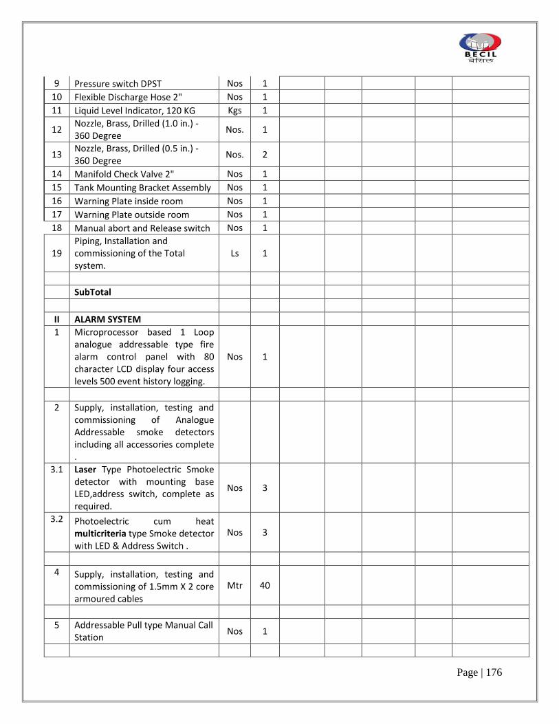
Page | 176
9 Pressure switch DPST Nos 1
10 Flexible Discharge Hose 2" Nos 1
11 Liquid Level Indicator, 120 KG Kgs 1
12 Nozzle, Brass, Drilled (1.0 in.) - 360 Degree
Nos. 1
13 Nozzle, Brass, Drilled (0.5 in.) - 360 Degree
Nos. 2
14 Manifold Check Valve 2" Nos 1
15 Tank Mounting Bracket Assembly Nos 1
16 Warning Plate inside room Nos 1
17 Warning Plate outside room Nos 1
18 Manual abort and Release switch Nos 1
19 Piping, Installation and commissioning of the Total system.
Ls 1
SubTotal
II ALARM SYSTEM
1 Microprocessor based 1 Loop analogue addressable type fire alarm control panel with 80 character LCD display four access levels 500 event history logging.
Nos 1
2 Supply, installation, testing and commissioning of Analogue Addressable smoke detectors including all accessories complete .
3.1 Laser Type Photoelectric Smoke detector with mounting base LED,address switch, complete as required.
Nos 3
3.2 Photoelectric cum heat multicriteria type Smoke detector with LED & Address Switch .
Nos 3
4 Supply, installation, testing and commissioning of 1.5mm X 2 core armoured cables
Mtr 40
5 Addressable Pull type Manual Call Station
Nos 1

Page | 177
6 Addressable Hooter with Flasher Nos 1
7 Addressable Monitor Module Nos 1
SUB TOTAL
TOTAL CARRIED OVER TO SUMMARY

Page | 178
SECTION III
SPECIFICATIONS
1. CIVIL & INTERIOR WORK
2. ELECTRICAL WORK
3. HVAC
3A. PAC
4. PLUMBING
5. IT Networking
6. Modular
7. Security Systems

Page | 216
1. CIVIL & INTERIOR WORK

Page | 217
TECHNICAL SPECIFICATION
TECHNICAL SPECIFICATION
1. PARTITIONS AND ASSOCIATED WORKS
1.1. Steel Framed Internal Partitions
1.1.A. Studs: Steel studs, non-load bearing “C” type studs roll-formed from 0.6mm Hot-dipped galvanized steel. Punch-outs, 25mm diameter, at 600mm Centers are provided for installation of services. Flanges shall be knurled to prevent screw slippage.
1.1.B. Top and Bottom Tracks: Wall stud track, roll-formed from 0.6mm hot-dipped galvanized steel. Flanges shall be angles 80 to provide friction fit to hold studs in place until Plasterboard is fixed. Track shall be in long lengths, in widths to suit the range of wall studs. Securely fix tracks to manufacturer’s recommendations, at a maximum of 600 centers.
1.1.C. Deflection Head Channel: Ceiling channel for deflection head assembly, roll-formed from 0.6mm hot-dipped galvanized steel with 25mm X 19mm cut-outs spaced 6mm apart.
1.1.D. Deflection Head Angle: Ceiling angle for alternative deflection head assembly. Formed from 0.6mm hot-dipped galvanized steel.
1.1.E. Deflection Head Top Track: Wall stud top track, roll-formed from 6mm hot-dipped galvanized steel. Legs are extended to 50mm to anticipated slab deflection.
1.1.F. Expansion Joint Components: Double sided PVC Closed Cell Foam Sealant, 5.5mm diameter, to be removed before plaster sets.
1.1.G. Storage: All materials used in the construction of Plasterboard Steel Drywall partition systems must be carefully stored and protected on the construction site. Plasterboard shall be stacked flat and protected from moisture.
1.1.H. Trimming of partition walls shall be as detailed and where openings are shown on plan and wall elevations. Trim for openings and form box studs at mullions and door jambs as shown.
1.1.I. At glazed screens fix 20 x 20 x 3mm natural anodized aluminum angle cover with mitered corners. Glass to be as specified in “Glazier”.
1.1.J. Internal Walls insulation shall be installed in the walls where scheduled : Insulation shall be Fiberglass batts : 2.85kg/m², 38kg/m³ for 75mm thickness; 2.5kg/m² for 50mm thickness; 50kg/m³ acoustic grade; or approved equivalent.
1.1.K. Abutments to Masonry Walls: Abutments to masonry walls shall be made using full height stopping beads and full height silicone joint seals.
1.1.L. Installation

Page | 218
i. Provide runner channels at raised floor as required. Align accurately. Secure at 400mm o.c. maximum.
ii. Where partitions extend to ceilings only, fasten with approved fasteners. iii. Place studs vertically at 400mm o.c. or as shown on Drawings and not more than
50mm from abutting walls, and at each side of openings and corners. Position studs in tracks at top and bottom. Cross brace steel studs as required to provide rigid installation to manufacturer’s instruction. Cross brace partitions over 2,736mm high, bracing channels at third points. Securely brace low partitions to provide rigid installation.
iv. Co-ordinate simultaneous erection of studs with installation of service lines. When erecting studs ensure we openings are aligned.
v. Provide double (boxed) studs extending full height at termination of walls, at change of line and generally at all openings and other shown on Drawings that are wider than the stud centers specified. Studs together 5mm apart use column clips or other approved means of fastening.
vi. Provide anchor plates over face of studs (spanning minimum 2 studs and screwed in place) directly behind all fixing devices (screws, bolts) for attachment of fitments.
vii. Install steel studs or furring channel between studs for attaching electrical and other boxes. Make provision in GI frame for AC grills etc.
viii. Maintain clearance under beams and structural slabs to avoid transmission of structural loads to studs. Use deep channel ceiling track as required accommodating deflection.
ix. In locations indicated, provide ceiling bulkhead consisting of metal studs, securely fastened in place. Space studs at 400mm o.c. and brace as required for stability. Use 92mm studs unless otherwise noted.
x. Brace ceiling height partitions with diagonal studs located in ceiling space as indicated on Drawings. Locate braces at 1200mm on centres and securely anchor to structure.
xi. Provide metal stud bulkheads over partitions designated to have lead sound baffles in ceiling space. Space and install metal studs as specified for partitions. Co-ordinate with other Trades for routing of services.
1.2. Wood Framed Internal Partitions
1.2.A. Framework: Hardwood frames, 50 x50 mm, spaced at 600 mm c/c. Use 100 mms
wood screw number 10 screwed into and hard wood gitti with inst into structural floor and slab with 12mm bit holes. All partition members shall be fixed with 35 mm number 8 screw and nails shall not be used.
1.2.B. Wood used for frameworks shall be free of knots and defects that interfere with structural aspects of the construction and shall be of uniform cross section.
1.2.C. All partition frames must be secured to structural slabs and in no event shall be affixed to false ceilings or false ceiling members.

Page | 219
1.2.D. Storage: All materials used in the construction of Plasterboard Steel Drywall partition systems must be carefully stored and protected on the construction site. Plasterboard shall be stacked flat and protected from moisture.
1.2.E. Trimming of partition walls shall be as detailed and where openings are shown on plan and wall elevations. Trim for openings and form box studs at mullions and door jambs as shown.
1.2.F. Internal Walls insulation shall be installed in the walls where scheduled : Insulation shall be Fiberglass batts : 2.85kg/m², 38kg/m³ for 75mm thickness; 2.5kg/m² for 50mm thickness; 50kg/m³ acoustic grade; or approved equivalent.
1.2.G. Abutments to Masonry Walls: Abutments to masonry walls shall be made using full height stopping beads and full height silicone joint seals.
1.2.H. All wood facing should be used only after fire proof paint and anti-termite treatment .
1.2.I. Installation i. Provide runner sections at floor as required. Align accurately. Secure at 600mm
c/maximum. ii. Place studs vertically at 600mm o.c. or as shown on Drawings and not more than
50mm from abutting walls, and at each side of openings and corners. Cross brace partitions over 2,736mm high, bracing channels at third points. Securely brace low partitions to provide rigid installation.
iii. Co-ordinate simultaneous erection of frames with installation of service lines. When erecting studs ensure the openings are aligned.
iv. Provide double frames extending full height at termination of walls, at change of line and generally at all openings and other shown on Drawings that are wider than the stud centers specified. Studs together 5mm apart use column clips or other approved means of fastening.
v. Maintain clearance under beams and structural slabs to avoid transmission of structural loads to studs. Use deep channel ceiling track as required accommodating deflection.
vi. Provide additional members at specified locations and hts for installation of graphics etc.
1.3. Gypsum Wallboard 1.3.A. Gypsum Wallboard: Thickness as noted on Drawings. Sheets to be of sizes required to
provide a minimum number of joints between sheets. Waterproof gypsum wallboard contractor to submit specification for designer approval.
1.3.B. Lead Sheet Sound Barrier: 0.8mm thick continuous cast, soft pig lead sheet weighting 9.765kg per m²and conforming to CSA HP2-1957(R1972).
1.3.C. Corner Bead: Galvanized sheet steel, minimum 0.59mm overall thickness, zinc coating Z275, minimum width of flanges 28.6mm for 12.7mm thick wallboard and 31.8mm for 15.9mm thick wallboard.
1.3.D. Casting Bead: Galvanized sheet steel, minimum 0.59mm overall thickness, zinc coating Z275, U-shaped designed for finishing with joint compound.

Page | 220
1.3.E. Resilient Sponge Tape: Self-sticking adhesive on one side, closed cell neoprene sponge tape, “Permastik” 122X by Jacobs and Thompson Ltd or foamed vinyl “Amofoam” by Arno Adhesive Tape Inc.
1.3.F. Wallboard Screws: Self-drilling, self-tapping gypsum wallboard screws, 25.4mm long #6 for single layer application, 41.3mm long #7 for double layer application if required. Corrosion waterproof gypsum board.
1.3.G. Joint Cement, Tape, Topping Compound and Accessories : As recommended by gypsum wallboard manufacturer.
1.3.H. Acoustic Sealant: As manufactured by CGC, Tremco or Presstite Division of Interchemical Corporation for acoustic partitions.
1.3.I. Acoustic Insulation: Sound attenuation Rockwool bracket, unfaced . 1.3.J. Before application of drywall commences, ensure that services have been installed,
tested and approved by relevant Jurisdictional Authorities and Designer; that conduits pipes, cables and outlets are plugged, capped or covered; and that fastenings and supports installed by others are in place.
1.3.K. Install work within 3.0mm of dimensioned location unless approved otherwise by Designer, and flat to tolerance of 3mm maximum in 5,750mm.
1.3.L. Back all joints with a framing member. 1.3.M. Install wallboard in maximum lengths and widths to minimize joints. Stagger end
joints where they are unavoidable. Locate joints in ceilings where least prominently discerned.
1.3.N. Form neat joints at mill ends and at field-cut edges of wallboard panels. Cut paper on face with a knife. Smooth by sanding and rubbing edges together.
1.3.O. Fasten wallboard to metal support members by sheet metal drywall screws at 150mm o.c., no closer than 12.5mm to and no further than 17mm from centre of joints. Do no force adjacent boards into place. Allow moderate contact. Provide extension clips where required. Drive screws to form a slight depression, but not so paper cover is broken.
1.3.P. Joint Treatment i. Fill joints, screw holes, and depressions on wallboard surfaces exposed to view to
provide smooth, seamless surfaces, and square, neat corners. Use jointing compounds and reinforcing tapes in conformance with manufacturer’s specifications. Ensure that wall board is tight against framing members, fasteners are properly depressed, and adhesives have sufficiently cured.
ii. Fill joints by three coat tape and joint filler method. iii. At external corners, install corner beads secured to framing at 150mm o.c. on
alternate flangers. Fill to nose of corner bead with joint filler and topping cement, as specified for beveled joints.
iv. Provide casing beads at all edges of wallboard exposed to view, where wallboard butts against other materials with no trim to conceal junction, at control joints, at perimeter of ceiling surfaces, at top of partitions where they stop against continuous ceiling surfaces, and where otherwise shown on Drawings, secure casing beads to framing at 150mm o.c.

Page | 221
v. At screw heads, fill holes and depressions with a two-coat application of joint filler.
1.4. Sound Retardant Partitions
i. Carry sound retardant partitions through ceiling space and terminate immediately below the structural deck unless otherwise indicated or in locations where lead sound baffles indicated.
ii. Provide approved impermeable sound insulation material to fill space between top of partition and structure to provide for deflection.
iii. Provide sound seal in all locations where structural members, pipes, ducts, etc. penetrate acoustic partition.
iv. Install sound retardant blanket, closely fit to stud framing and the like and extend full height of partition.
v. Seal full perimeter of cut-outs around electrical boxes, ducts etc. Seal openings in outlet boxes and the like.
vi. Do not locate outlet boxes back to back. 1.5. Fire Retardant Gypsum Board
1.5.A. 1 Hour fire rating required non-combustible for BS476 (or equivalent IS); Part 4 standards.
1.5.B. All fixing installation as per manufacturers details to provide rating. 1.5.C. Product : Suparlux
1.6. Preparation for Finish: Gypsum board to be properly prepared to accept surface finish.
Approved gypsum board primer to be painted on walls. 2. CARPENTRY AND JOINERY
2.1. Scope of Work 2.1.A. Work under this section includes providing all necessary materials, labour, plant,
transportation and services for the completion of work shown on the drawings and including the following : Rough and finished carpentry, joinery, doors and frames.
2.2. Basic workmanship
2.2.A. The rates for carpentry and joinery work are to include for all cutting and waste, notching, holes, housing ends, miters, ends and shaped ends, angles, junctions, heading joints, short lengths, etc. for all nails, spikes, pins or brads, for coating the backs of frames, backing fillets, etc, with two coats of approved wood preservative, and for all necessary templates or moulds for circular work states “plugged to walls, etc.” the prices are to includes for plugging and fixing with nails, spikes, etc. to brickwork, block work or concrete work, and any hacking off and clearing away existing plaster as necessary. The rates shall also include for the provision of all samples and shop drawings.
2.2.B. Joinery is to be prepared immediately after the placing of the Contract, framed up, bonded and wedged up. Any portions that wrap or develop shakes or other defects are

Page | 222
to be replaced before wedging up. The whole of the work is to be framed and finished in a proper and workmanlike manner, in accordance with the detailed drawings, wrote where required and fitted with all necessary metal ties, straps, bolts, screws, glue, etc. Running bonded joints are to be cross-tongued with teak tongues and where over 12mm thick, double cross-tongued.
2.2.C. Should joints in Joiner’s work open, or other defects arise within the period stated for maintenance in the Contract, and the cause thereof be deemed by the Designer to be due to unseasoned timber or faulty or bad workmanship, such defective joinery shall be taken down, refitted, redecorated and/or replaced if necessary and any work disturbed shall be made good at the Contractor’s expense.
2.2.D. Exposed Joinery shall have a high degree of finish and shall be of the best quality throughout.
2.2.E. Joinery shall comply with the detail drawings. Prepare joinery for stained or tinted finishes. Conceal all fastenings where possible. Punch rail heads below surface and fill with putty colored to match finish. Adhesive and jointing compounds shall be non-staining and kept off visible surfaces. Surface screws where necessary shall, if visible, be Philips Head, countersunk flush.
2.2.F. The Contractor shall provide all fixings, fastenings, anchors, plugs and the like of approved type to transmit the loads and stresses imposed and ensure the rigidity of the assembly.
2.2.G. Carcass work, shelving and framework to built-in and freestanding units shall be generally constructed of plywood or MDF board as described and specified, properly housed, grooved, tongued, glued, blocked and screwed together as per manufacturers guidelines, and entirely to the satisfaction of the Designer.
2.2.H. All exposed surfaces of joinery to be properly finished. All laminated surfaces to be finished on both sides of MDF or Plywood regardless of drawing.
2.3. Protection of Finished Work
2.3.A. The Contractor shall be responsible for providing and maintaining any boxing or
other temporary coverings required for the protection of dressed or finished work that might be damaged during the progress of the work if left unprotected. He is to clean out all shavings, cut ends and other waste from all parts of the Works before coverings or infillings are constructed.
2.4. Timber
2.4.A. Timber generally shall be the best of its kind and of the species indicated on drawings and on the Materials and Finishes Specifications Chart. It is to be thoroughly seasoned and kiln dried, with moisture content not less than 12% and not more than 20%. It is to be free from worm holes, large loose or dead knots or other defects, sawn die square and without warping, splitting or other defects. Where exposed it is to be matched for colour and graining.
2.4.B. Timber is to be cut to the required sizes and lengths as soon as practicable after the works are begun and stored under cover, so that the air will circulate freely around it.

Page | 223
2.4.C. Unless otherwise stated all timber is to be finished all round and all sizes shown on drawings or specified are finishes sizes.
2.5. Medium Density Fiberboard
2.5.A. Fabrication, Lamination and Finish of MDF to conform to National Particleboard
Association technical guide “MDF from Start to Finish”.
2.5.B. MDF (Medium Density Fiberboard) to have the following properties (minimum) for 9, 12, 16, 18mm thickness.
Light board Standard
Density 600kg/m³ 725kg/m³
Internal bond 700KPa 850KPa
Modulus of rupture 36.0MPa 36.0MPa
Modulus of elasticity 2600MPa 3000MPa
Thickness Tolerance
1 hour thickness swell: 0.15mm 0.15mm
- 18mm 1.5% 1.5%
- 12mm 2.6% 2.6%
1 hour water absorption :
- 18mm 2.5% 1.5%
- 12mm 3.5% 2.4%
Moisture Content 7.5% 8.0%
2.5.C. Screw Holding
Screw type: Parallel thread. Screws such as the Twin fast or particle board screws. Wood screws not to be used.
Maximum screw gauge is: 12mm board thickness – 6 16mm board thickness – 7 18mm board thickness – 8
Pilot Hole recommended avoiding splitting during edge screw fixing, drilled approximately 2.3mm beyond the expected depth of insertions of the screws. Screw position should be decided in relation to board thickness and screw size and not less than 25mm from corners. Screw must not be over tightened as further turning reduces the holding strength.
2.5.D. Nails and Stapling

Page | 224
Add adhesive to joint prior to assembly. Nails to be either annular, groove or helical of 13 or 14 gauge.
2.5.E. Sanding and Finishing Use 120 grit paper followed by 240 or 320 grit paper.
2.5.F. Painting Prior to priming for paint finishes all nail holes to be stopped with solvent based wood dough and lightly sanded. Solvent or turps based systems recommended.
2.5.G. Formaldehyde Emissions
MDF board manufactured to comply with industry’s voluntary emission standard of 0.3ppm at a loading of 0.08 ft² of product surface per cube foot of room space.
Sealing finish required to all exposed areas including edges, backs and underside of drawers, etc. Acceptable wet coatings area : oil wood primer and enamel top coat, latex-ammonia coatings plus two coats of latex water base wall paint.
2.5.H. Storage/Fabrication MDF have to be fabricated and stored according to manufacturer’s instructions. MDF must be stored and fabricated in controlled environment.
2.6. Plywood
2.6.A. Plywood shall be best quality close grained plywood suitable for veneering, painting
or bonding plastic laminate. It is to be a resin bonded weatherproof brand, exposed edges will be finished with an edge strip of solid wood, tongued and grooved and glued, or as detailed.
2.7. Joints
2.7.A. Joints shall be as indicated on detail drawings. The contact surfaces of dowels, tenens, wedges, etc. shall be glued with a best quality cold setting, synthetic resin adhesive of moisture resistant, gap filing type or with best quality cold-setting case in glue. Where glued joinery is likely to come into contact with moisture the glue shall be waterproof. Animal glues are not to be used.
2.7.B. Nails, spikes, bolts, etc. shall be of the best quality mild steel or wrought iron except in those places where brass headed nails are indicated on drawings. All screws are to be brass unless otherwise stated. Refer to item 5.02.04 (ii) and (iii) for MDF board.
2.8. Templates 2.8.A. Templates, boxes and moulds shall be accurately set out and rigidly constructed so as
to remain accurate during the time they are in use. 2.9. Grounds
2.9.A. Grounds are to be clean sawn, free from large knots, splayed as required, plugged and fixed to walls, etc. at 450mm centers.
2.10. Plugs

Page | 225
2.10.A. Where joiners work is to be plugged to walls, etc. Raw plugs, Phili plugs or plugs or similar and approved pattern shall be used. The use of wooden plugs will not be permitted.
2.11. Preservative 2.11.A. All unexpected surfaces of timber, e.g. false ceilings, backing fillets, backs of door
frames, cupboard framing, grounds, etc. are to be treated with two coats of an approved timber preservative or vacuum pressure impregnated with an approved water soluble timber preservative before fixing or bedding.
2.12. Door and Fixed Glazing Frames 2.12.A. Frames to doors fixed glazing etc. shall be of approved hardwood timber or MDF
board as specified and will be constructed in full accordance with the detail drawings, to the required sizes and with all necessary mouldings and other labours, morticed and tenoned and put together in the method indicated using the materials and finishes specified.
2.13. Doors 2.13.A. Refer to door schedule and drawings for size type, thickness and hardware
(ironmongery). 2.13.B. Unless otherwise shown on the contract drawings the door shall be constructed as
follows : i. Hollow Core Doors: Hollow core doors are to be of 19mm plywood covered with
paint grade, timber veneer or 1.6mm plastic laminate as required. The doors are to be lipped on all edges with a 9mm timber twice splay rebated ending mitered at angles. Lippings to meeting stiles of doors are to be 25mm thick rebated or rounded as required.
ii. Solid Core Doors: Solid core doors are to be framed up with 50mm hardwood mitered edge and filled in with a core of 45mm MDF board to receive finish of paint, veneer or laminate or as per drawings.
2.13.C. Fabrication i. Fabricate doors in accordance with MDF manufacturer’s guidelines. ii. Hardwood edge to be one piece and same species as face veneer or birch timber
veneer for paint or plastic laminate finish. iii. Stiles and rails to be of sufficient width to accommodate surface mounted or
concealed hardware (min 100 mm stiles). iv. Undercut on rebate bottom rails as required. v. Reinforce for locks and other hardware.
2.13.D. Finishing i. Doors to be pre-finished and delivered to site ready to be hung. ii. All exposed edges to be sealed prior to delivery to site.
2.13.E. Fitting and Hanging i. Hang full height doors on four pair butts, unless otherwise noted, to close fully in
all cases. ii. Provide 1.5mm clearance at head and jambs, 7 mm clearance over carpet and
6mm over thresholds.

Page | 226
iii. Hang doors according to manufacturer’s instructions where prefabricated frames (i.e. Jeb System) are used.
2.13.F. Installation of Finish Hardware i. Make hardware cuts in timber finishes neat and true, fit and adjust hardware
according to manufacturer printed instructions. ii. After installation, place wrappings on knobs pull etc. (as protection until
completion of contract). iii. Carefully safeguard keys to ensure that unauthorized personnel do not have
access to them. On completion of work deliver keys to employer with suitable tag attached to each key indicating the door operated thereby.
2.14. Skirting’s 2.14.A. Provide and fix MDF or timber skirting’s or as specified, where shown in the Schedule
of Finishing, on hardwood grounds securely plugged to walls, scribed to floors and properly mitered at angles. All skirting to be medium density fibreboard where specified.
2.14.B. All skirting’s are to be accurately scribed to fit the contour of any irregular surface against which they should form a close butt connection.
2.15. Fire Protection Treatment 2.15.A. Timber materials above finished ceilings should be avoided. However, if necessary,
timber ceilings and support materials above ceilings shall have fire retardant treatment. 2.16. Fixing of Timber to Concrete
2.16.A. Fixing of timber to concrete or brick work shall be by : i. Hardened steel pins direct into concrete or brickwork for fixing small sections such
as skirtings and architraves. The head shall be punched home and filled. ii. Preformed plugs such as “Rawplug” or similar approved in formed holes. iii. Plastic compounds such as “Rawplug Fixate” or similar approved in formed holes. iv. Expanding bolts such as “Rawplug Fixrite” or similar approved in formed holes. v. Cartridge operated hand tools such as but shall not be used within 50mm of any
edge. 2.16.B. Care must be taken to locate any buried pipes, cables, or other services when fixing
timber to concrete or brickwork. If any hole hits reinforcement it must be repositioned. 2.16.C. Fixing of timber to metal shall be by :
i. Self tapping screws in thin sheet. ii. Bolts in preformed holes (tapped as required). iii. Cartridge operated hand tools.
2.17. All fixings shall be as instructed by the Designer 2.17.A. Boards and linings, other than tongued and grooved, and less than 180mm wide on
face, shall be secured with 2 mails at each fixing position or joist. The nails shall be not less than 12mm not more than 20mm from edges. Boards and linings other than tongued and grooved, and more than 175mm wide on face, shall be secured with 3 nails at each fixing position or joist. The outer nails shall be not less than 12mm not more than 20mm from the edge.
2.17.B. Tongued and grooved boards and linings less than 100mm wide on face shall be secured with one nail at each fixing position or joist. Tongued and grooved boards and

Page | 227
linings more than 100mm wide on face shall be secured with 2 nails at each fixing position or joist.
2.17.C. All nails shall have a length of not less than : i. Plain boards and linings, 2.1/2 x thickens. ii. Tongued and grooved boards and linings, 2 x thickness. iii. All boards and linings shall be secured with hammer driven nails unless specified
to be fixed with screws. When screws are specified they shall be not less than No. 8 and nor shorter than 2 thickness.
iv. All finished work shall be smooth, free from abrasion, tool marks, raised grain grade markings or similar defects on exposed surfaces.
v. Foam padding, pressed moulded fiberglass and mineral wool shall be to the Designer’s approval.
vi. Protect finished and prefinished surfaces from work of other trades. 2.18. Plastic Laminate
2.18.A. Plastic decorative laminated sheeting will be of the brand, catalogue number, colour etc. shall be as approved by the Architects. Samples of all finishes must be submitted to the Architects for approval prior to usage. Unless otherwise shown or specified the laminate sheeting shall be 1.5mm thick on all flat surface, 1 mm thick on vertical surfaces and 0.8mm thick sheets shall be used on post formed surfaces as required. Laminates shall be veneered to mounting surface with an approved waterproof and heatproof area based cement, used in strict accordance with the manufacturer’s instructions. Rubber based adhesive shall not be used. Sheeting must not be applied to timber with a moisture content of more than 15% or at temperature of less 15ºC (60F). The sheeting is to be applied only to close grained plywood or medium density fiberboard to ensure a smooth ripple free surface; it is not to be applied to open grained plywood such as fire plywood. Underside surface of counter tops and shelves which are faced with plastic laminate shall have corresponding 0.8mm backing sheet applied. Cabinet doors faced with plastic laminate shall have corresponding 0.8mm backing sheet applied. Cabinet doors faced with laminate shall receive the same laminate on all exposed surfaces (on the back side and edges). Top sheet shall be placed on and over finished edge unless otherwise noted. Edges not faced with laminate, as at field joins, shall be machined and sealed. Butt joining of laminates shall be minimized by using longest available lengths where required, and all butt joints shall be perfectly flush and sealed.
2.18.B. No surface sanding of laminated plastics is permissible. 2.18.C. Unless otherwise specified, all laminated plastics shall have the standard matte
finish. 2.18.D. Samples showing the surface texture and pattern are to be submitted to the Designer
for approval before fixing. 3. METALWORK 3.1 Hardware Generally

Page | 228
3.1.I The hardware throughout shall be of approved manufacture and supply, well made and equal in every respect to the samples to be deposited with the Designer. All the ironmongery shall be provided by the Contractor and shall be of approved manufacture and obtained from nominated suppliers or other approved sources.
3.1.II All ironmongery shall met with requirements of the following relevant standards unless otherwise stated : BS1227, BS5872, BS4951, BS3725, BS4112, BS1331 and BS2088 (or equivalent IS codes)
3.1.III The rates for hardware are to include for supplying necessary screws to match and for the provision of keeps, striking plates, etc. as necessary. The rates for fixing hardware are to include for all fittings, cutting, sinking, forming, mortising, first fixing, removing for decoration, finally re-fixing after execution of the decoration, easing, oiling, adjusting, making good and leaving in perfect working order to he satisfaction of the Designer. Screws for fixing ironmongery items shall generally be in accordance with BS1494 Part 2 (or equivalent IS codes).
3.2 Hardware Finishes 3.2.I Exposed hardware shall have the finish specified on the Hardware Schedule and it shall
normally be assumed that all hardware on each item, if not specified otherwise shall have identical or similar non-staining, non-tarnishing finish.
3.2.II Screws are to match the finish of the article to be fixed and to be round or flat headed or countersunk as require.
3.2.III Chromium plating, where specified, is to be on a base material of copper or brass and is to accord with International and British Standards for chromium plating for normal outdoor conditions.
3.2.IV Unless otherwise specified aluminium shall have an anodized finish and comply with samples approved by the Designer.
3.2.V All solid brass, brass sheeting or brass plating specified in polished finish shall be further finished with two pack clear polyurethane coating for non-staining, non-tarnish protection from discoloration unless otherwise specified.
3.3 Strength 3.3.I All steel, brass, bronze, aluminium and stainless steel articles shall be submitted to a
reasonable test for strength if so required by the Designer at the Contractor’s expenses. 3.4 Protection 3.4.I Brass and bronze surfaces are to be protected with a thick grease or other suitable
protective material, i.e. clear lacquer coating. This protective coating is to be renewed as necessary and cleaned off at completion of work.
3.5 Completion 3.5.I Upon practical completion the Contractor shall ensure that the following requirements
are carried out : 3.5.I.1 Remove all protective covering, clean all items of ironmongery and ensure that they are
in proper working condition. 3.5.I.2 Each set of keys shall be provided with an approved circular chromium plated brass plate
25mm dia. X 1.5mm thick stabled with the identification of Floor/Unit/ Door to which it belongs for handing over to Employer.

Page | 229
3.5.I.3 Properly arrange wrenches, spare parts and lock spurner wrenches, spare parts and any other tools furnished by the manufacturers with the ironmongery for handing over to the Employer.
3.5.I.4 Properly arrange in a file guarantees and certificates etc. of the manufacturers furnished with the ironmongery, if any, for handing over to the Employer.
3.6 Bolts 3.6.I Provide all bolts, nuts, washers and other metal fittings required in the work where
applicable. 3.7 Stainless Steel 3.7.I Stainless steel to conform to BS1449 Part 4 (or equivalent IS codes). All stainless steel
shall be of polished mirror finish hairline finish or baked enamel as identified in finishes schedule.
3.7.II Gauge of material to be confirmed by Contractor. 3.8 Mild Steel 3.8.I Mild steel to conform to BS1449 Part 1 (or equivalent IS codes). 3.9 Wrought Iron 3.9.I Wrought iron is to be selected tough metal with an even silky fibrous grain, formed clean
and free from slaws and cracks, etc. 3.10 Aluminium 3.10.I All aluminium shall either receive a polished bronze or gold colour anodic coating to the
Designer’s approval and to BS1470 and BS1474 (or equivalent IS codes). 3.11 Decorative Metalwork 3.11.I Brass/bronze, polished chrome, stainless steel, for trim, panels, frames, railings, fittings,
etc, shall be solid first quality metal in sizes and thickness shown in detailing. All exposed joints will be welded and ground smooth and attachments shall be concealed. Finish shall be bright high mirror polished or hairline apAne greyance and coated with an approved suitable clear sealer.
3.11.II Metal angles, retainer clips, support angles, etc. shall be in mild steel. They shall be primed and painted with two coats of semi-gloss enamel with colour to match surface on which metal is fastened.
3.11.III Brass trim for all areas shown shall be standard 0.050 GA or similar, prefinished brass plated steel.
3.11.IV Fabricate and assemble brasswork with true sharp profiles and minimum of joints. Necessary joints shall be hairline, tight butted. Use concealed fasteners throughout for securing brasswork to subtracts.
3.12 Cast Iron 3.12.I Cast iron to be approved gray metal, sound, free from flaws, blow holes, etc. and have a
clean smooth surface. 3.13 Protection of Metals 3.13.I All galvanized metal shall be galvanized by hot dip process in accordance with BS729 Part
1 (or equivalent IS codes)chromatic passivated (to allow for immediate painting without the use of a mordant solution).
3.13.II All non-galvanized ferrous metal shall be coated with one shop coat or priming before delivery to site.

Page | 230
3.13.III All aluminium work in contact with dissimilar metals or with materials containing alkalines, e.g. concrete, cement and like mortar shall be painted with two coats bituminous paint on the contact surfaces.
3.13.IV All decorative metalwork shall be protected with a suitable factory applied covering which shall not be removed without the approval of the Designer.
3.14 Workmanship 3.14.I The work shall be carried out in accordance with the requirements of the Local Building
By-Laws and to be satisfaction of the Local Building Authorities empowered to control the quality of the work in the district where the work is situated and the Contractor must acquaint himself of such requirements which may effect his price. The Contractor shall comply with all reasonable instructions and directions given from time to time by the Designer and/or his Representative for the purpose of ensuring that the work shall be carried out in accordance with this Specification and completed at the proper time.
3.14.II All work shall be in accordance with the best practice and workmanship and materials shall be to the approval of the Designer. Any defective work which does not comply with the Specification or Drawings shall be removed and replaced by the Contractor at his own expense.
3.15 Products 3.15.I Hinges and magnetic catch for new cabinets, heavy duty (50 Kg) roller tracks for drawers
to be supplied and install by Contractor. Full extension drawer runners to be Hafele soft roller 60 KTS or equal.
3.16 Scope of Work 3.16.I Work under this section includes providing all necessary materials, labour, plant,
transportation and services for the completion of work shown on the drawings and include the following :
3.16.I.1 Sundry metal sections in fixing partitions to underside structural slab. 3.16.I.2 Sundry metal sections in framing and architectural detailing. 3.16.I.3 Hardware for all doors and furniture. All timber doors to be provided with four number
hinges. Full height doors to have four pair hinges. 4 PLASTER 4.1 Cement: Cement shall be ordinary Portland cement complying with BS12 (or equivalent IS
codes). 4.2 Sand: Sand for plastering, etc. shall comply with the requirements of BS 1198 and 1199 (or
equivalent IS codes) and shall be clean, sharp naturally occurring sand or shall consist of crushed rock or gravel. It should be clean, hard, free from adherent coatings and vegetable matter. It shall not contain soft. Porous or flaky grains or crushed dust, alkali, loam, clay or any deleterious organic matter.
4.3 Water: Water to be clean, free from acids, alkalis and other harmful matter. 4.4 Plastering 4.4.I All plastering, unless otherwise described, shall be applied in two coats to walls to a total
thickness of 12mm finished with a steel trowel. Plastering to ceilings and soffits shall be similar. All arises shall be slightly rounded.

Page | 231
4.4.II All plastering with cement and sand (1:6) mix shall be with plasticiser and shall comply with BS/IS.
4.4.III Provide drips where shown on the drawings. All brickwork shall be thoroughly cleaned, the joints raked out and well wetted before and kept dam during rendering. Concrete surfaces to be hacked for key before rendering.
4.4.IV The Contractor shall protect all plastering work in accordance with usual trade practices and he shall replace any damage work at his own expense.
4.4.V The Contractor shall obtain the Designer’s approval of the plastering works prior to removing his workmen and equipment off the site.
4.4.VI All wall and ceiling plaster shall be properly made good around all pipes, brackets, gratings and similar intrusions.
4.4.VII Plaster shall be continued into grooves and rebates in door and window frames and finished against metal windows with slightly cover internal angles.
4.4.VIII Wire mesh should be provided over all joints, over pipes, different materials. 5 GLAZING 5.1 Scope of Works: Work under this section includes providing all necessary materials, labour,
plant, transportation and services for the completion of work shown on the drawings and in general includes the following : Glazed partitions, windows and doors.
5.2 Glass 5.2.I All glass to be of best quality of approved manufacture, and be free from bubbles, smoke
wanes, air holes and other defects. It is to accord with the indications given on the Material Selection Schedule.
5.2.II Plate or float glass shall be clear, of selected glazing quality. Glass generally to conform to BS952 (OR EQUIVALENT IS CODES))and glazing to be CP152.
5.2.III Tempered glass shall have structural integrity and shall not contain any harmful scratches, pinholes, and unevenness, sharp angled or field edge.
5.2.IV Putty for glazing in wood sashes shall be approved tropical putty. For glazing to metal, approved patent mastic shall be used.
5.2.V The glass shall be well bedded and carefully back puttied, sprigged in and fixed with beads. The glass shall be neatly cut to fit the rebates with 3mm clearance all round and the rebates shall be primed before glazing.
5.2.VI “Plexi-glass” shall be to the Designer’s approval. 5.2.VII Where mirror within cabinet or interior works is required, it shall be as far as possible,
cut off at site. 5.2.VIII Mirrors shall be fixed with approved glue and wood beading to plywood backing and
excess glue to be carefully cleaned off prior to completion or with 3m high bond tape of adequate area to hold the mirror in place.
5.2.IX Upon completion, all glass and mirror shall be cleaned both sides and any broken, cracked or defective panes shall be replaced at Contractor’s own expense. 5.2.X Etched glass to conform to industry standard and pattern, size and detail to material
selection schedule and drawings. 5.2.XI Cost of making holes as per details to be included.

Page | 232
5.3 Mirror Glass 5.3.I Mirror glass shall be 6mm float glass of silvering quality backed with a reflective surface
layer of chrome silver or other metal, a protective layer of copper, a coat of protective mirror backing paint and a coat of moisture sealer.
5.4 Delivery: Glazing to be delivered to site in cut sizes, in packages bearing the manufacturer’s name and/or trade mark. The type, quality, thickness or weight of the glazing is to be clearly marked on the package.
5.5 Cutting of Glass and Mirror: In cutting glass, proper allowance shall be made for expansion. Each square of glazing to be as large as possible. Glazing is to comply with requirements of BS Code of Practice 152 (equivalent IS codes). All glass edges to be properly machine ground and polished.
5.6 On Completion: On completion, clean all glazing, replace all cracked, scratched or broken sections and leave in good condition to the satisfaction of the Designer.
5.7 Gaskets: Gaskets for glazing shall be preformed rubber gaskets to BS4255 Part 1 (or equivalent IS codes) on approved neoprene gaskets, to be used strictly in accordance with the manufacturer’s printed instructions.
6 VINYL TILE, SHEET VINYL 6.1 Scope of Works 6.1.I.1 Refer to the Drawings for details of required vinyl floor tiling works. 6.1.I.2 The Contractor shall check on site and allow for any making good work to existing
floor for vinyl tiling in tendering. 6.2 General 6.2.I The vinyl flooring to be installed is to be in accordance with the details on Tender
Drawing set. 6.2.II The sub floor is to be completely clean and dry before laying. Tiles are to be set out from
the centre of all rooms and passage to that any cutting required takes place at the extremities. The tiles are to be glued to the sub floor with an approved glue. All marks of the glue are to be removed form the surface of the tiles and the tiles are to be waxed before handover.
6.2.III Sheet vinyl to be installed as per manufacturers guidelines. Seams to be properly sealed. 7 STONE, CERAMIC TILE 7.1 General 7.1.I Stone/ tile shall be in the colors, types, sizes, finishes, and thickness and the
Manufacturers as shown by the drawings and specified herein, or as approved 7.1.II Unless otherwise shown on drawings or specifications stone shall have a polished finish,
on all exposed surfaces; concealed surfaces may be sawn. 7.1.III Visual : All examinations, selections and approvals shall be for the purpose of achieving a
final apAne greyance of Stone with greatest possible uniformity and will be based upon the following criteria.
7.1.III.1 All Stone shall be of sound stock and uniform texture and shall be free from holes, seams, shakes, colour variations, clay pockets, spills, stains, starts and other defects

Page | 233
which would impair the strength, durability and appearance of the work, as determined by the Architect.
7.1.III.2 Inherent variations characteristic of the Stone and the quarry from which the Stone is to be obtained shall be brought to the attention of the Architect at the time the samples are submitted for approval and shall be subject to approval of the Architect. Stone provided at time of installation shall be of same quarry, colour, veining and other characteristics as approved by Architect.
7.1.III.3 All Stone shall be selected for background colour, veining, marking and matching shall run in even shades and shall be set accordingly.
7.2 Accessory Materials for Stonework 7.2.I Mortar materials shall be as recommended by the Manufacturer for each Stone type,
size and application. Mortar colour shall be as selected by Designer. 7.2.II For colour pointing mortar, furnish matching Stone ground down to meet grading
requirements for sand. 7.3 Stone Support: Where required, Stone support systems, anchors and accessories shall be
manufactured by a company specializing in the design and fabrication of Stone approved by the Designer. Provide all fastening devices, support angles, relieving angles, anchors, coping anchors, dowels, cramps, bolts, nut, shims, expansion shields, flashing etc., necessary to properly secure Stone to the structure as required.
7.4 Fabrication 7.4.I Stone shall be accurately cut to sizes, shapes, profiles and dimensions. There shall be no
deviation from jointing. 7.4.II Exposed surfaces and edges of Stone units shall be free from cracks, broken corners,
chipped arises, scratches or other defects affecting appearance. 7.4.III Patching or filling not permitted. 7.4.IV Cut Stone units full and true on faces, reveals, beds, joint and top, to the full dimensions
required by drawings. All edges shall be straight and true with sharp and true arises. All Stone shall fit together accurately.
7.4.V Make faces of Stone Units in same plane flush at joints. All finished surfaces shall be true in line and face.
7.4.VI Sawn surfaces and edges shall be cleaned of all rust stains and iron particles. 7.4.VII No patching or use of Stone with chipped edges or faces shall be permitted. 7.4.VIII Provide holes and sinkages required for anchors, dowels, other devices required to
support and/or suspend Stone, and to accommodate other items which connect to or penetrate the Stone.
7.4.IX Include all cutting, drilling and fitting of Stonework required to accommodate the work of other trades. In cutting and fitting carefully cut and grind edges to a neat tight fit. Do cutting in such a manner so as not to in pair strength or apAne greyance of Stone. Use physical templates for all cutting and drilling; obtain required templates from proper trades.
7.5 Inspection: Contractor to advise requirements relating to his placement of any inserts which are to be used for anchoring and supporting stonework.
7.6 Erection Tolerances :

Page | 234
7.6.I The work shall be designed to accommodate all permitted tolerances and anticipated dead and live load movement, creep, sway and torsion of the structure without any harmful effects.
7.6.II Patching or hiding defects in Stone will not be permitted. 7.6.III Clean Stone before setting as recommended by Stone Manufacturer. Follow all
Manufacturer directions during installation. 7.6.IV Connections : Anti-galvanized Action : Isolate dissimilar metal surfaces to prevent
galvanic action. Separate metal surfaces in such a manner that metal does not move on metal. Materials used for this purpose shall be low friction components, sealants or gaskets.
7.7 Setting Stone/ tile 7.7.I Mortar and grout shall be as recommended by Stone Manufacturer for size, weight,
location and use of Stone Color as selected by Designer. 7.7.II Mix mortar for setting Stone on anchor plates and for spotting back of Stone. Mix
approved non-shrinking cement for filing of anchor holes in accordance with Manufacturer’s directions.
7.7.III Mix mortar in small batches to make a stiff plastic mass; mix until thoroughly homogenous; re-tempering with water is prohibited.
7.7.IV Set Stone in accordance with drawings and final shop drawings for Stonework. Provide anchors, supports, fasteners and other attachments shown or necessary to secure stonework in place. Shim and adjust accessories as required for proper setting of Stone. Completely fill holes, slots and other sinkages for anchors, dowels, fasteners and supports with non-shrink grout during setting of Stones.
7.7.V Maintain even joints between units, 1mm maximum unless noted otherwise on drawings.
7.7.VI Grout joints full and flush with face of Stone. Where metal inset strips are indicated, butt Stone flush and tight against strips with no gaps exceeding 0.8mm.
7.7.VII Cleaning: After final cleaning of Stone, re-point any open joints with grout. 7.7.VIII Protection: Cover the installed stone with 2 layers of polythene and POP 3 mm thick for
protection until handover. 7.8 Repair and Cleaning (After Erection) 7.8.I Remove and replace Stone units which are broken, chipped, stained or otherwise
damaged. Where directed, remove and replace units which do not match adjoining stonework. Patching or hiding defects in stonework will not be permitted. Provide new matching units, install as specified and reseal joints to eliminate evidence of replacement. Reseal defective and unsatisfactory joints to provide a neat, uniform appearance.
7.8.II Clean vertical stonework after completion of work, using clean water and stiff-bristle brushes. Do not use wire brushes, acid type cleaning agents or other cleaning compounds with caustic or harsh fillers.

Page | 235
8 PAINT 8.1 Scope of Works: Work under this section includes providing all necessary materials, labour,
plant, transportation and services for the completion of work shown on the drawings and in general including the following : Doors, frames and partitions, Carpentry and joinery.
8.2 General 8.2.I No paint shall be used on the work until the Designer has inspected the materials and
given instruction for the work to proceed. 8.2.II Paints shall be supplied on site in the markers’ sealed containers and must be thoroughly
mixed or stirred before use and mixed and used strictly, in accordance with the manufacturer’s instructions.
8.2.III Paints shall be of anti-fungus quality and of approved manufacture. 8.2.IV Knotting shall be of approved manufacture and consist of shellac dissolved in
mentholated spirits. 8.2.V Linseed oil for use on joinery shall be best clear boiled linseed oil well rubbed in. 8.2.VI The works three coats of paint shall means: a) Gypsum Board 1 coat latex primer 2 coats acrylic emulsion (Eggshell finish) b) Woodwork 1 coat wood primer (Opaque finish) 2 coats alkyd trim enamel (Semi gloss finish) c) Woodwork Stain to match sample (Natural finish) 2 coats d) Faces to which wallcovering 1 coat primer to be applied
e) MDF- spray applied system 1 coat primer, Dulux Interior Primer
Undercoat 66 line or equal 1 coat interior primer
1 coat ‘top coat’ Dulux Super or equal Stain Finish or sealerStain Dulux Timbaglow stain to match sample
1 coat Dulux Timaglow plyurethane satin 2 cost Dulux Timaglow polyurethane stain or
gloss 8.2.VII The respective types of finishes to surfaces to be painted shall be that as stated in the
Interior Finish Schedule or above. 8.3 Primers and Paints 8.3.I All emulsion paint, primers, and paints except where otherwise described, shall be Jotun
Paints or other approved equal and cement paint shall be “Super Snowcem” or other equal and approved.
8.3.II The primer for paint on ferrous metal work shall be red oxide or lead primer, and the primer for paint of non-ferrous metal work shall be zinc chromatic primer.

Page | 236
8.3.III Wood sealer shall be of an approved manufacture and applied strictly in accordance with the manufacture’s instruction.
8.3.IV The emulsion paint shall be of the Polyvinyl Acertate (PVA) type. 8.3.V Bituminous paint shall be of an approved brand applied in accordance with the
manufacturer’s instruction. 8.3.VI Wax polish for wood surface shall be obtained from an approved manufacturer. 8.3.VII Silicon based water repellents shall conform to BS3826 Class’A’ (or equivalent IS codes). 8.3.VIII Epoxy paint shall be Jotun Epoxy Chemical Resistant Finish F430-Line or other approved
and to be applied all in accordance with the manufacturer’s instructions. 8.3.IX Alkali-resisting primer shall be a solvent based primer obtained from the maker of the
undercoat and finishing coat. 8.4 Special Wall Coating 8.4.I This work to be carried out by nominated sub-contractor as indicated. 8.4.II Job mock up: 8.4.II.1 Minimum 1 sample area application of specified coating systems on each type of surface. 8.4.II.2 Upon approval by Designer, mock-ups to serve as standard for the work. 8.4.II.3 Mock-ups to be left in place as part of completed project. 8.4.II.4 Applicator (certified by manufacturer): Applicator shall certify in writing that technician
utilized for work in this section have been trained by the manufacturer. Applicator shall include in his certification that specialized equipment as required by the manufacturer will be used for work in this section.
8.4.II.5 Product to conform to specifications and product requirements as indicated in manufacturer’s specifications.
8.5 Job conditions: 8.5.I Apply coating only under the following prevailing conditions : 8.5.I.1 Air and surface temperatures not below 50ºF 8.5.I.2 Prevent wide variation of temperature which might result in condensation on freshly
coated surfaces. 8.5.I.3 Protect surfaces not to be coated 8.5.I.4 Areas broom clean & free of excessive dust. 8.5.I.5 Adequate illumination. 8.5.II Examine surfaces to be coated and report any conditions that would adversely affect the
apAne greyance or performance of the coating systems and which cannot be put into an acceptable condition by specified surface preparation.
8.5.III Prior to all surface preparation and application until the surface is acceptable or authorization to proceed is given by the Designer.
8.5.IV Before applying special coating, thoroughly clean all surfaces. 8.5.V Schedule all cleaning so that dust and other contaminants from the cleaning process do
not fall on wet, newly coated surfaces. 8.5.VI All surfaces shall be clean, dry and adequately protected from dampness. Surfaces shall
be smooth, even and true to place, and free of any foreign material which will adversely affect adhesion or apAne greyance of applied coating.

Page | 237
8.5.VII Mildew shall be removed and neutralized. 8.5.VIII Before coating is applied, surfaces shall be tested with moisture-testing device. No
coating shall be applied when moisture content exceeds 12% except as many be required by the manufacturer of the coating materials used. Test sufficient area in each space and as often as necessary to determine the proper moisture content for application.
8.5.IX Patching and repair of defects and damage to drywall, concrete, masonary and other materials refer to related section.
8.5.X Provide recommended priming for all surfaces to receive special coating. 8.5.XI Contractor shall sand and reprime for all abrasions and damage spots in the surface of
the prime coat before proceeding with subsequent finish coat. 8.5.XII The number of finish coats required is shown on the schedule hereinafter. The coats
scheduled are field applied coats, and shall be in addition to prime coats or any special preparation.
8.5.XIII Should any coat of coating be deemed unsatisfactory, it shall be sanded and additional coats applied as necessary until satisfactory finish is achieved.
8.6 Colours 8.6.I All tints, shades and colors of paints shall be selected by the Designer and the priming,
undercoat and finishing coats shall be obtained from the same manufacturer. 8.6.II The tints of undercoats are to approximate those of the finishing color. 8.6.III In order to indicate the number of coats applied a different shall be made in the tint of
each succeeding coat. 8.7 Workmanship: 8.7.I All surfaces to be painted shall be thoroughly dusted and cleaned on, cracks cut out,
holes stopped, steelwork cleaned of rust etc., in accordance with approved general practice.
8.7.II Each coat of paint shall be dry and well rubbed down before the next is applied. 8.8 Plastered Surfaces 8.8.I All dust, dirt plaster splashes or efflorescence shall be brushed off or removed by wiping
first with a dry coarse cloth and then with a damp cloth. 8.8.II If efflorescence is present, the surface shall then be left for 48 hours to see if further
efflorescence occurs. 8.8.III The internal plastered or concrete surfaces shall be treated initially with a coat of anti-
alkali primer and subsequently with two coats emulsion paint. 8.8.IV The external plastered and concrete surfaces shall be treated with one coat of stabilizing
solution and two coats “Sandtex Matt” sand-based paint. 8.9 Fibrous Plasterboard Surfaces (Drywall Surfaces) 8.9.I Fibrous plasterboard surfaces requiring painting shall be thoroughly cleaned to remove
dirt and dust. 8.9.II The board shall first be primed before applying filler. A normal plasterboard filler shall be
applied and rubber down to give the desired surface. 8.9.III Apply three coats of emulsion paint to board surfaces. 8.10 Wood or MDF Board Surfaces 8.10.I Woodwork which is to be painted shall be thoroughly cleaned to remove dirt, grease,
etc.

Page | 238
8.10.II All cracks, crevices and holes shall be scraped out, primed and made good with hard stopping, faced up and rubbed to an even surface.
8.10.III The hard stopping shall be of an approved make or made up of paste, white lead and gold size stiffened with whiting.
8.10.IV All knots in woodwork shall be treated to prevent bleeding. Large and loose knots shall be cut out and replaced with sound wood or cut back and the surface made good with filter. Smaller knots shall be treated with two thin coats of knotting.
8.10.V Woodwork surfaces shall be primed with one coat of wood primer well-brushed in. 8.10.VI Unexposed timber framing and backs of wood frames built in contact with masonry shall
be painted with two coats wood preservative. 8.10.VII All internal surfaces of cabinets, shelves, cases, stations, etc. where visible when doors
are opened, shall be sealed or finished with laminate. 8.10.VIII “Oil stain clean lacquer”, “stain and polish”, “lacquer” shall mean two coats of stain and
two coats of clear catalytic lacquer for a fine furniture finish and that “paint” shall mean one coat of primer and three coats of emulsion paint.
8.10.IX Painting to wood veneer shall consist of light oil stain to match coloration of design sample and shall be sealed with multiple coats of clear flat sealer and sanded between coats in the workshop. Final finish shall have 20-40% reflective sheen and shall match design sample.
8.10.X JOTUN paints, brand systems are recommended for spray application on MDF board. 8.11 Ferrous Surface 8.11.I Surfaces shall be thoroughly cleaned down to remove all dirt, grease etc. and all rust and
seals shall be entirely removed by chipping, scraping or wire-brushing and a perfectly clean surface obtained.
8.11.II Immediately after preparation, the surface shall be primed with one coat of metallic primer well brushed on, before the subsequent application of two coats of gloss enamel paint.
8.11.III No paint shall be applied to a damp surface and no external painting shall be carried out during wet weather.
8.11.IV On no account shall the Contractor allow his employees to empty washings or painting materials into sanitary fittings or drainage systems and the Contractor must provide a suitable receptacle outside the building to receive such and the receptacle with contents must be removed from the site at completion by the Contractor.
8.12 Non-Ferrous and Galvanized Surfaces 8.12.I Non-ferrous and galvanized exposed surfaces which are to be painted shall be
thoroughly cleaned down or degreased by washing with white spirit. 8.12.II Surfaces shall then be roughened by lightly rubbing down with steel wool, wire-brush or
abrasive paper and cleaned down. 8.12.III When required, mordant solution shall be used for the preparatory treatment. 8.12.IV Immediately after preparation, the surfaces shall be primed with the coat of zinc
chromatic primer, well brushed on, before the subsequent application of one undercoat and one finishing coat as directed.
8.13 Clear Varnish: Clear varnish to conform with BS 256 (or is equivalent)

Page | 239
8.14 Clear Polishing: Woodwork requiring to be polished shall be stopped with hard stopping and rubbed down and polished with an approved polished applied in two separate coats.
8.15 Samples: Samples showing colours of all paints to be used shall be prepared by the Contractor as and when directed by the Designer for his approval and at the Contractor’s own expense. Three samples of each paint finish to be submitted for approval by Designer.
9 WALLCOVERING 9.1 Scope of Work: Work under this Section includes providing all necessary materials, labour,
plant, transportation and services for the completion of work shown on the drawings including the following : Partitions and Doors.
9.2 General 9.2.I The Contractor will make good all holes and indentation, touch up including hair cracks
rub and sand down to a smooth and level surface for the existing walls before the application of the wall covering.
9.2.II The Contractor will apply an approved alkali resisting primer to seal all walls to receive wall covering.
9.2.III The Contractor will first install on single layer of approved lining paper (to be hung horizontally) using an approved adhesive.
9.2.IV The Contractor will install all wall coverings with the manufacturers specified pre-mixed adhesive which is to be applied thoroughly and evenly to the back of the wall covering.
9.2.V All joints are to be perfectly met with both ends wiped clean of surplus adhesive. A clean roller or brush is to be used to drive out all air bubbles.
9.2.VI Where applicable pattern matching must be perfect. 9.3 Clean Up: When the Contractor has completed the installation all areas are to be cleared of
excess materials. All left over rolls or half rolls are to be turned over to the Employer. 9.4 Supervise: All work on site shall be done under the direction of a capable supervision who
has had a minimum of 12 years experience in this type of work. 10 SUSPENDED FALSE CEILING WORKS 10.1 Scope of Work 10.1.I Work under this section includes providing all necessary materials, labour, plant,
transportation, and services for the completion of work shown on drawings. 10.2 General Requirements on Construction and Installation 10.2.I The Contractor shall provide complete suspension system and related accessories for
each and every panel of the suspended ceilings independently. Where in areas the suspension system cannot be suspended directly from the soffits of concrete slabs due to the pressure of service pipings or ducting, the Contractor shall provide all necessary straps, hangers and brackets to form independent support for the suspension system.
10.2.II All suspension system, unless otherwise stated, shall be fabricated from corrosion resistant material. If they are of such materials that react with aluminium they shall be separated from the aluminium by materials that do not react with it adversely.
10.2.III Fixing of suspension straps or hangers to concrete or brickwork with cartridge fired fasteners shall be carried out by means of an automatic Cartridge operated hand tool,

Page | 240
used in accordance with the manufacturer’s instruction. Alternatively, the fixing may be carried out by mortising and inserting fibrous inserts of other approved fixing materials and using suitable nails or screws.
10.2.IV Natural anodized finished to exposed aluminium members shall be in accordance with BS1615:1972 (or IS equivalent). The anodic coating shall have a minimum average thickness of 0.0004 (10 micron).
10.2.V All openings in the ceiling to accommodate installation of light fittings, sprinkler heads, air-conditioning grilles, return air slots, speakers, smoke detectors, etc. shall be provided by the Contractor. The Contractor shall allow in his tender for all necessary cuttings, framing, suspension system and addition edge trims and hangers in connection with the provision of such openings.
10.2.VI The ceilings shall be installed to patterns shown on the reflected ceiling plans and the Contractor shall allow herein all the necessary cuttings, wastages, etc. to obtain the pattern as shown on the reflected ceiling plans.
10.2.VII Ceiling boards should be installed after all wet work are completed and dried and after all mechanical and electrical work in the plenum space are installed.
10.2.VIII The edges of all the ceiling shall be properly cut to fit neatly against the curved walls, beams or any other structural members and the Contractor shall provide for all the necessary edge trimmings angles bent to fit the profile.
10.2.IX All ceiling components shall be aligned true with level surfaces and straight lines. Deflection of any component must not exceed 1/360 of the span between supports.
10.2.X On completion of installation, no dirt, spots or marks shall appear on the exposed surfaces.
10.2.XI All damaged or improperly installed units shall be removed and replaced at Contractor’s own expenses.
10.3 Nominated Contractor’s Design Recommendation and Other Information 10.3.I For the complete assessment of the Contractor’s design solutions, the Contractor must
submit together with his tender the following: 10.3.II Design Recommendation and Calculations. 10.3.III Preliminary Shop Drawings showing salient details, in particular, suspension details of all
types of suspended ceilings. 10.3.IV Brochures and descriptive literatures of the materials and goods offered. 10.3.V Sample of ceiling panels, aluminium suspension tees, etc. and certificates from the
Director of Fire Services. 10.4 Suspended Ceilings 10.4.I Gypsum Ceilings 10.4.I.1 Gypsum or drywall shall be India Gypsum or other approved equivalent. 10.4.I.2 All gypsum board ceilings shall be installed in accordance with the manufacturer’s
written instructions. 10.4.I.3 Gypsum Board to be 2400mm approx. length of 1200mm width and 12mm thickness, to
have 2 opposing edges rebated. 10.5 Timber Ceilings 10.5.I Lattice ceilings shall be fixed to pattern as shown in the drawings.

Page | 241
10.5.II Lattice ceilings shall consist of 38mmx9mm slats and fixed to sawn timber framing which shall be of approved sizes and installed at approved centres.
10.5.III Tongue and groove ceilings shall be fixed to pattern as shown on the drawings. 10.5.IV Tongue and groove ceiling shall consist 76mmx20mm boards and fixed to sawn timber
framing which shall be of approved sizes and installed at approved centres. 11 WINDOW TREATMENT 11.1 Louvre Blinds 11.1.I Vertically and horizontal blinds shall be by Winfab or similar manufacturer approved by
the Interior Designer. Louvres shall be in plastic, aluminium alloy, wood or other materials as shown on the drawings. Blinds shall be manufactured to an approved sample. Louvres are to be straight, true and tree from kinks, twists, scratches nicks or other blemishes.
11.1.II Metal accessories shall be in rust proof alloy to approved finish and colour. Cord and pulls shall be in nylon, terylene or similar artificial fibre. Rods are to be in nylon, timber as approved.
11.1.III Existing Blinds: Where the installation is to match existing blinds they are to be taken down, checked repaired and thoroughly cleaned prior to re-installed.
11.2 Protection: The Contractor shall be responsible for protecting all drapes and tracks in those areas of work forming part of this contract. The Contractor shall make good or replace at his own expense any damaged work caused through lack of adequate protection or case in installation.
11.3 Completion: On completion of the installation of drapes and track the Contractor shall leave all work clean and perfect.
12 PLUMBING AND SANITARY WORKS 12.1 Pipes 12.1.I Salt Glazed Stoneware Pipes : Stoneware pipes shall be class A with IS marking, salt
glazed, sound, free from cracks, deformities and imperfections in glazing. They shall be cylindrical, straight and to standard dimensions. They shall be made of hard burnt stoneware of dark gray colour, and thoroughly glazed and shall give a sharp clear note when struck with a light hammer. The pipes shall conform to the requirements of Indian Standard No. 651-1971.
Internal Dia Thickness of barrel & socket
100 mm 12 mm
150 mm 16 mm
250 mm 20 mm
12.1.II Cement Concrete Pipes: The pipes shall be with or without reinforcement as required and shall be of specified class. These shall conform to IS: 458-1971. The reinforced concrete pipes shall be manufactured by centrifugal (or spun) process while un-reinforced cement concrete pipes by spun or pressure process. All pipes shall be true to

Page | 242
shape, straight perfectly sound and free from cracks and flaws. The external surface of the pipes shall be free from defects resulting from imperfect grading of the aggregate mixing or moulding.
12.1.III Concrete used for the manufacture of un-reinforced and reinforced spigot and socketed pipes and collars shall not be leaner than 1:2:4 (1 cement: 2 coarse sand: 4 graded stone aggregate). The maximum size of aggregate should not exceed one third of the thickness of the pipe or 20 mm whichever is smaller. The reinforcement in the reinforced concrete pipes shall extend throughout the length of the pipe. The circumferential reinforcement shall be adequate to withstand the specified hydrostatic pressure and further bending stresses due to the weight of water when running full across a span equal to the length of pipe plus three times its own weight.
12.1.IV Centrifugally Cast (Spun) Pipes: The spun iron pipe shall conform to IS: 1536-1989. The spun iron pipes shall be of cast iron casted centrifugally and vary in diameter from 80mm to 750mm. These shall be either of class LA, class A or class B as specified.
12.1.V Specials: The specials shall conform to IS: 1538-1976. 12.1.VI Pipe - Cast Iron (Vertically Cast): The pipes shall conform to IS: 1537-1976. The pipes shall
be either with spigot and socket ends or flanges ends. The pipes shall be of cast iron casted vertically and vary in diameter from 80mm to 1500mm. These shall be of either class A or class B as specified.
12.1.VII Specials: The specials shall conform to IS: 1538-1976. 12.1.VIII Spigot and socketed Soil, Waste and Ventilating pipes: Sand Cast Iron and Centrifugally
Cast ( Spun) Iron Pipes and Fittings. 12.1.IX Sand cast iron spigot and socket soil, waste and ventilating pipes, fittings and accessories
shall conform to IS: 1729-1979. Centrifugally cast (spun) iron spigot and socket soil, waste and ventilating pipes, fittings and accessories shall confirm to IS: 3989 - 1984. All pipes and fittings shall ring clearly when struck with light hammer.
12.1.X All pipes and fittings shall be coated internally and externally with the same materials at the factory, the fitting being preheated prior to total immersion in a bath containing a uniformly heated composition having a tar or other suitable base. The coating material shall have good adherence and shall not scale off. In all instances where the coating materials has a tar or similar base it shall be smooth and tenacious and hard enough not to flow when exposed to a temperature of 770 C but not so brittle at a temperature of 00 C as to chip off when scribed lightly with a pen knife.
12.1.XI The access door fittings shall be designed so as to avoid dead space in which filth may accumulate. Doors shall be provided with 3mm rubber insertion packing and when closed and bolted, these shall be water tight.
12.1.XII All pipes shall have uniform wall thickness for the entire length. These shall conform to IS: 1729-79/ IS: 3989-70.
12.1.XIII The standard weights and thickness of pipes shall be as shown in the following table. A tolerance upto minus 10 percent may however be allowed against these standard weights.
S.No Nominal Dia of Bore (mm)
Thickness (mm)
Overall Weight of Pipes excluding ears (kg)

Page | 243
1.5 M Long 1.8 M Long 2 M Long
1 50 5 9.56 11.41 12.65
2 75 5 13.83 16.52 18.37
3 100 5 18.14 21.67 24.15
4 150 5 26.70 31.92 35.66
12.1.XIV Fittings : Fittings shall b e easy clean type. The thickness of fittings and their sockets and spigot dimensions shall conform to thickness and dimensions specified for the corresponding sizes of straight pipes as per IS codes.
12.1.XV Jointing : Soil, waste, vent or anti-siphonage and rain water pipes shall be jointed with refined pig lead conforming to IS:782. Sufficient skein of jute rope shall be caulked to leave a minimum space for pig lead as given in para 2.8.4 to be poured in. After the pouring the lead shall be caulked into the joint with caulking tool and hammer. All surplus lead shall be cut and joint left flush with the rim of the socket neatly.
12.1.XVI Galvanized Iron Pipes and Fittings: The pipes shall be galvanized mild steel medium / heavy as shown in drawings or as specified, conforming to IS: 1239-1973 Part I & II. All pipes shall be electric resistance welded screwed with taper, threads and sockets shall be cleanly finished, well galvanized in and out and free from cracks, surface flaws, laminations and other defects. All screws threads shall be clean and well cut. The ends shall be cut cleanly and square with axis of the tube.
12.1.XVII The fittings shall comply with all the requirements that of pipes. The fittings shall be designated by the respective nominal bores of the pipes for which they are intended. The standard weight and thickness of pipes shall be as shown in the following table.
Nominal Bore (mm)
Series/ Class Wall Thickness (mm)
Nominal weight of black tube (kg/m)
Nominal weight of galvanized tube (kg/m)
15 Medium = M 2.65 1.22 1.274
Heavy = H 3.25 1.45 1.505
20 M 2.65 1.58 1.642
H 3.25 1.90 1.953
25 M 3.25 2.44 2.525
H 4.05 ------ 3.053
32 M 3.25 3.14 3.247
H 4.05 3.84 3.937
40 M 3.25 3.61 3.731
H 4.05 4.43 4.545
50 M 3.65 5.10 5.236
H 4.50 6.17 6.329
65 M 3.65 6.51 6.711
H 4.65 7.90 8.065
80 M 4.05 8.47 8.696
H 4.85 10.10 10.309
100 M 4.50 12.10 12.658
H 5.40 14.40 15.085

Page | 244
Nominal Bore (mm)
Series/ Class Wall Thickness (mm)
Nominal weight of black tube (kg/m)
Nominal weight of galvanized tube (kg/m)
150 M 4.85 19.20 20.000
H 5.40 21.20 22.222
12.2 Sanitary Fixtures 12.2.I All glazed vitreous china sanitary ware fixtures shall be of first quality and of the best
Indian make of approved manufacture conforming to IS: 2556. These shall be non porous and fully vitreous with all the visible portions perfectly glazed and should be absolutely free from hair cracks, pinholes and local imperfections. These shall have perfect symmetrical, uniform and smooth curves.
12.2.II All plumbing sanitary fixtures and fittings shall be stored in covered stores and handled carefully to prevent damage. The sanitary fittings shall be installed at the correct assigned positions as shown on the drawings and as directed by the Engineer-in-charge. Fixtures shall be installed by skilled workmen with appropriate tools according to the latest practices in the trade. Manufacturer's instructions shall be followed for the installation of the fixtures.
12.2.III Fixtures in all toilets shall be of standard weight mounted rigid, plumb and true to alignment. The outlet of water closet pans and similar appliances shall be examined to ensure that outlet ends are abutting properly on the receiving pipes before making the joint. It shall be ensured that the receiving pipes are clear of obstruction. When fixtures are being mounted, attention shall be paid to the possibility of movement and settlement by other causes. A check shall be made to ensure that necessary anchoring devices have been provided for supporting water inlet for lavatory, basins, sinks, flushing cisterns and other appliances. Where the built-in types of brackets are used they shall be securely fixed to the slabs and walls by approved means. It shall be ensured that while fixing the fixtures and fitting no tool marks or scratches are developed.
12.2.IV Protection of Fixtures : Care shall be taken at all times, particularly after fixing to protect fixtures from damage. All opening shall be temporarily plugged during progress of work to prevent obstruction. Fixtures shall be finally cleaned to the satisfaction of the Engineer-in-charge.
12.2.V Flushing Cisterns, Foot Valve and Flushing Pipes : The flushing cistern shall be automatic or manually operated, high level or low level, as specified, for water closets and urinals.
12.2.VI Cisterns shall be cast iron, vitreous china or pressed steel and plastic, as specified, complying with the requirements of IS: 774-1984, IS: 2326-1987 and IS: 7231-1984 respectively.
12.2.VII The body thickness of a cast iron cistern shall not, at any place, less than 5mm and that of vitreous china 10mm. The body of a pressed steel cistern shall be of seamless or welded construction of thickness not less than 1.6mm before coating, and shall be porcelain enameled. The cistern shall be free from manufacturing faults and other defects affecting their utility. All working parts shall be designed to operate smoothly and efficiently. A cistern shall be considered mosquito proof only if there is no clearance

Page | 245
anywhere which would permit a 1.6mm wire to pass through in the permanent position of the cistern i.e. in the flushing positions or filling position.
12.2.VIII The breadth of a low level cistern from front to back, shall be such that the cover or seat, or both of water closet pan shall come to rest in a stable position when raised.
12.2.IX The cistern shall be supported on two cast iron brackets of size as approved and embedded in cement concrete 1:2:4 block 100x75x150mm. The cast iron brackets shall conform to IS: 775-1970. These shall be properly protected by impervious paint. Alternatively the cisterns shall have two holes in the back set above the overflow level for screwing into the wall, supplemented by two cast iron wall support painted with one coat of primer and two coats of enamel of approved shade.
12.2.X The cistern shall have a removable cover which shall fit closely on it and be secured against displacement. The outlet fitting each cistern shall be securely connected to the cistern. In the case of high level cisterns, the outlet shall be 32mm nominal bore and in the case of low level cisterns, the outlet shall be of 40mm nominal bore.
12.2.XI Ball cock shall be of screwed type 15mm diameter and shall conform to IS: 1703-1968. 12.2.XII In the case of high level manually operated cistern the lever arm of the cistern shall have
a suitable hole near the end through which split ring of 'S' hook type shall pass. A chain shall be attached to the ring or hook. The chain shall be of G.I. and strong enough to sustain a suddenly applied pull of 10 Kg or a dead load of 50 Kg without any apparent or permanent deformation to the shape of the link. The chain shall terminate with a suitable handle for pull. The finish shall be smooth and free from burrs. In case of low level flushing cisterns, the handle shall be of chromium plated brass.
12.2.XIII The cast iron cisterns shall be painted with two coats of black bitumastic paint on the inside and two or more coats of paint of approved quality and shade on the outside.
12.2.XIV In the case of manually operated cisterns the syphonic action of the flushing cistern shall be capable of being rapidly brought into action by the operating lever, but shall not self siphon or leak. The discharge rate of the cistern shall be about 5 litters in 3 seconds, when connected to an appropriated flush pipe, and there shall be no appreciable change in the force of flush during the period of discharge.
12.2.XV G.I. flush pipe: The flush pipe shall be of (a) medium quality galvanized iron having a normal internal diameter of 32mm. The flushing pipe shall be of suitable length with bends etc. as required for fixing it with front or the back inlet W.C. pan, (b) Polyethylene pipes, low density conforming to IS: 3076-1985 or high density conforming to IS: 4984-1987, (c) unplasticized pipes conforming to IS: 4985-1988.
12.2.XVI Overflow Pipe : 12.2.XVI.1 G.I. overflow pipe shall be of 20mm nominal bore and shall have a non corrodible
mosquito proof brass cover, having 1.25mm dia perforation. 12.2.XVI.2 The plastic overflow pipes shall be manufactured from high density polyethylene
conforming to IS: 4984-1972 or unplasticized PVC conforming to IS: 4985-1988. 12.2.XVII C.P. Brass Flush pipe and bend for low level Cistern: The flush pipe / bend should be
heavy quality C.P. brass 40mm dia. The plating shall conform to IS: 4827-1983. Electroplated of chromium on brass.
12.2.XVIII Seats and Covers of Water Closet: These shall conform to IS: 2548-1967. These shall be made of moulded synthetic materials, which shall be tough and hard with high resistance

Page | 246
to solvents and shall be free from blisters and other surface defects and shall have C.P. brass hinges and rubber buffers. These shall be free from twist and the underside shall be flat and underside edge shall be arrised. Each seat shall have at least four rubber buffers of suitable size.
12.3 Stainless Steel Sink and Draining Board: These shall be of approved make of pressed stainless steel 1.2mm thick sheets and shall have 40mm dia outlet with grating. These shall be connected to 40mm dia C.P. brass 'P' bottle traps or directly with G.I. pipe. Stainless steel sinks shall conform to IS: 13983-1994. These shall be supported on C.I. cantilever brackets or placed on wooden or marble counter. The joint between the masonry or wood work shall be filled with mastic filler to make it absolutely water right. The draining board shall be sloped towards the sink in order to drain out all the water in the sink.
12.4 Bath Tubs : These shall be of cast iron or pressed enameled or polymarble / acrylic, one piece construction including integral overflow and drain out conforming to IS: 3489 with detachable, adjustable, foot of approved manufacture. The interior and the turned over edges of the tub shall be evenly coasted with vitreous enamel thoroughly fused to base. The enameling shall conform to IS: 772-1973 or as revised. The enameling surface shall be glossy, smooth and free from cracks, chips and other flaws which affect the appearance of the serviceability of the tubs. The exteriors of the bath tub except edges shall be painted with two coats of enamel or any other approved paint of specified shade over a priming coat of red lead.
12.5 Water Supply Fixtures : 12.5.I All supply fittings (including mixing fittings and accessories) shall be of brass/copper;
heavy chromium plated, or approved make and design specified. The fittings shall be cast fittings, screw type, machined and threaded properly for fixing to the supply pipes.
12.5.II The plating shall conform to IS: 4827-1983. Electroplated coating of nickel and chromium on brass / copper and copper alloys.
12.5.III The fittings shall be supplied complete with chromium plated matching flanges and extension pieces of required lengths. C.P. brass metallic washers where required shall also be of chromium plated brass. All bib cocks and stop cocks shall conform to IS: 781-1984. Bib taps and stop cocks for water services, sand cast brass screw down (revised) pillar cocks shall conform to IS: 1795-1982 pillar taps; mixing fittings to IS: 1701-1960 Tub spout, shower arm rose, spout and other fittings shall match the supply fittings and appearance. All fixing accessories and screws shall be similar to fittings with all exposed parts chromium plated. All washers shall conform to IS: 4346-1967 washers for water taps for cold water services.
12.6 Waste fittings : All waste fittings ( waste, chain, pop-up, overflow) shall be of brass / copper, heavy chromium plated of the make and design specified and match the supply fittings. They shall conform to IS: 2963-1979 waste fittings for wash basins and sinks.
12.7 Bottle traps : Bottle traps (for wash basins, sinks, baths etc.) shall be deep seal (minimum 6 seal) cast brass bottle traps, heavy chromium plated. All bottle traps shall be provided with suitable cleaning eye, extension piece flare nut - all chromium plated. Bottle traps shall be of approved make and design. Traps for wash basins shall be 32mm (1-1/4 inch) for sinks 40mm (1-1/2) inch.

Page | 247
12.8 Wall Caps: Wall caps shall be provided on all walls, floors, columns etc. wherever supply and disposal pipes pass through them. These wall caps shall be chromium plated brass snugly fittings and shall be large enough to cover the puncture properly and shall conform to IS: 4291.
12.9 Brass Bib Cock, Stop Cock and Pillar taps: 12.9.I The brass bib cock and stop cock shall be polished bright and shall conform to IS: 781-
1984. The minimum finished weights of bib tap (cock) and stop tap (cock) shall be as given in the IS specifications as reproduced below.
12.9.II When the bib or stop cocks are required to be chromium plated the chromium plating shall be of grade B type conforming to IS: 4827-1983. The chromium shall never be deposited on brass unless a heavy coating of nickel in interposed. In case these are required to be nickel plated, the plating shall be of first quality with a good thick deposit of silver whiteness capable of taking high polish which will not easily tarnish or scale.
12.9.III Pillar taps: Pillar taps shall be chromium plated brass and shall conform to IS: 1795. The nominal sizes of the pillar taps shall be 15mm or 20mm as specified. The chromium plating shall be of grade B type conforming to IS: 4827-1983.
12.9.IV Finished weights of 15mm to 20mm dia pillar taps shall be as shown in the table below. 12.10 Valves 12.10.I All valves (gate, globe, check, safety) shall be either all brass or gunmetal valves suitable
for the particulars service. All valves shall be of the particulars duty and design called for. 12.10.II Valves shall be tested to 21 kg/m2 pressure at manufacturer's work. Valves shall either
be of the screw type or flange type with suitable flanges and non-corrosive bolts and gasket; tail pieces as required shall be supplied along with valve. Gate, globe and check valves shall conform to IS: 778-1984 and non-return valves to swing check type reflex (non-return) valves IS: 5312 (Part-I) 1969.
12.10.III Sluice Valve: Sluice valves, where called shall be flanged sluice valves of cast iron body. The spindle, wall seat and edge nuts shall be of gunmetal. They shall have rising spindle and shall be of the particular duty and design as per specification.
12.10.IV The valves shall be supplied with suitable flanges, non-corrosive bolts and asbestos fibre gaskets. Sluice valves shall conform to IS: 780-1984 and IS:2906-1984.
Size Minimum finished weight
Bib tap in Kg Stop cock in Kg
15 mm 0.40 0.40
20 mm 0.75 0.75
Particular Weights (gm)
15 mm 20 mm
Body 255 505
Washer plate loose valve 15 28
Back nut 40 50
Tap 650 1175

Page | 248
12.10.V Ball Valves with Floats: Ball valves with floats to be fixed in storage tanks shall consist of cast brass lever arms having copper balls (28 SWG) screwed to the arm integrally. The copper ball shall have bronze welded seams. The closing / opening mechanism incorporating the position and cylinder shall be of a non corrosive metal and include washers. The size and construction of ball valve and float shall be suitable for desired working pressure operating the supply system. But valves shall be supplied with brass hexagonal beechnuts to secure then to the tanks and a socket to connect to supply pipes.
12.10.VI All ball valves with floats shall conform to IS: 1703-1989. 12.11 Ferrule: The ferrules for connections with C.I. main shall generally conform to IS: 2692-1989.
IT shall be of the non-ferrous material with a C.I. bell mouth cover and shall be of nominal bore as specified. The ferrule shall be fitted with a screw and plug or valve capable of completely shutting off the water supply to the communication pipe if and when required.
For fixing ferrule the empty main is drilled and tapped at 45o in the vertical and the ferrule screwed in. The ferrule must be so fitted that no portion of the projection of the shank shall be left projected within the main into which it is fitted.
12.12 Water Meters: 12.12.I Water meters of approved make and designs shall be supplied and installed at locations
as shown. The water meters shall meet with the approval of the local supply authorities. Valves and chambers to house the meters shall also be provided along with meters.
12.12.II All meters shall conform to IS: 779-1968 or IS: 2373-1968 and of approved manufacture. Where called for water meters shall be located in masonry chambers or appropriate size as indicated.
12.13 Pipes Hangers, Brackets etc.: Sturdy hangers, brackets and caddles of approved design shall
be installed to support all pipe lengths which are not embedded over their entire runs. The hangers and brackets shall be of adjustable heights and painted with red oxide primer, and two coats of enamel paint of approved make and shade. Clamps, coils and saddles shall be provided to hold pipes with suitable gaskets of approved quality. The brackets and hangers shall be designed to carry the weights of pipes safely. Wherever required pipes may run along ceiling level in suitable gradient and supported on structural clamps. Spacing for clamps for such pipes shall be as follows:
12.14 Pipes Sleeve: Adequate number of sleeves (pipe inserts) of Cast Iron or Mild Steel shall be provided where pipes cross through concrete, masonry and similar work. The pipe inserts shall be provided with removable timber plugs to keep foreign matter out till installation of the services pipe cross the sleeve. The diameter of sleeve should be one size higher than the proposed dia or as instructed by the Engineer-in-charge.uPVC pipes and fittings.
Vertical Horizontal
G.I. Pipes 300 cms 240 cms
H.C.I. Pipes 180 cms 120 cms

Page | 249
12.15 uPVC pipes for drainage system shall be rigid uPVC pipes of class 6/10 kg/cm2 as specified, conforming to IS: 4985-1988.
12.15.I Fittings for pipes shall be injection moulded with approved type of sockets and 'O' rings joint.
12.15.II Jointing shall be done as per the manufacturers recommendation. The pipes and fittings must have matching dimensions for a perfect joint. Loose or excessively tight joints in the system shall not be accepted. Fittings must have sufficient gap (approx. 10mm) for permissible thermal expansion of pipes.
12.15.III Use proper uPVC pipe adapters for connections between cast iron pipes, traps and uPVC pipes.
12.16 Fittings: Fittings shall conform to same Indian Standards as for pipes. Contractor shall use pipes and fittings of matching specifications.
12.16.I Fittings shall be of required curvature with or without access door. 12.16.II Access door shall be made up with 3 mm thick insertion rubber washer and white lead.
The bolts shall be lubricated with grease or white lead for easy removal later. the fixing shall be air and water tight.
12.17 Fixing: 12.17.I All vertical pipes shall be fixed by M.S. clamps truly vertical. Branch pipes shall be
connected to the stack at the same angle as that fittings. No collars shall be used on vertical stacks. Each stack shall be terminated at top with a cowl ( terminal guard ).
12.17.II Horizontal pipes running along ceiling shall be fixed on structural adjustable clamps of special design shown on the drawings or as directed. Horizontal pipes shall be laid true to slop and clamps adjusted to proper levels so that the pipe fully rests on them.
12.17.III Contractor shall provide all sleeves, openings, hangers, inserts during construction. He shall provide all necessary information to the Engineer-in-charge for making such provisions in the structure as necessary. All damages shall be made good to restore the surfaces.
12.18 Traps 12.18.I Floor traps: Floor traps shall be of cast iron, deep seal with an effective seal of 50 mm.
The trap and waste pipes shall be set in cement concrete blocks firmly supported on the structural floor. The blocks shall be in 1:2:4 mix (1 cement: 2 coarse sand: 4 stone aggregate 20mm nominal size) and extended to 40 mm below finished floor level. Contractor shall provide all necessary shuttering and centering for the blocks. Size of the block shall be 30x30 cms and of required depth.
12.18.II All H.C.I. soil / waste pipes in sunken pipes in sunken portion shall be encased in cement concrete 1:2:4 (1 cement: 2 coarse sand: 4 stone aggregate 20 mm nominal size) 75mm thick alround.
12.18.III Urinal trap: Urinal traps shall be cast iron P or S trap with or without vent and set in cement concrete block as specified in 1.23.1 without extra charge.
12.18.IV Floor trap inlet : Bath room traps and connections shall ensure free and silent flow of discharging water. Where specified, contractor shall provide a special type G.I. / M.S. inlet hopper without or with one, two or three inlet sockets to receive the waste pipe.

Page | 250
Joint between waste and hopper inlet socket shall be lead caulked. Hopper shall connect to a C.I. P or S trap with at least 50mm water seal. Floor trap inlet hoppers and traps shall be set in cement concrete blocks as specified in para 1.23.1 without any extra cost.
12.19 C.P. stainless steel gratings 12.19.I Floor trap and urinal trap shall be provided with 110-150 mm square or round C.P. /
Stainless steel grating, with rim of approved design and shape. Minimum thickness shall be 4 mm.
12.20 Laying and jointing of G.I. pipes and Fittings: Where pipes have to cut or re-threaded, ends
shall be filled out so that no obstruction to bore is offered. The end of the pipes shall then be threaded conforming to requirements of IS: 554-1955 with pipes dies and tapes carefully in such a manner as will not result in sacking of joints when two pieces are screwed together. The pipes shall be cleaned and cleared of all foreign matters before being laid. All pipes and fittings shall be properly jointed to make the joints completely water right and all pipes kept free from dust and during fixing burr shall be removed after screwing. Pipes passing through wall or floor shall be provided with M.S. tube sleeves one size higher than the outside dia of pipe when directed by the Engineer-in-charge.
12.21 Insulation Material: Insulation material shall be resin bonded Fibre glass, mineral wool or approved equivalent. The thermal conductivity of the insulation material shall not exceed
0.043 K Cal/sqm/deg c/mm. at 32oC (90o F) means temperatures and density shall not be less than 24 Kg/m3 (1.5 lb/cubic foot). Thickness of the insulation shall be as specified for the type of services. Bonding of insulation material shall be with a cold setting compound. Samples of insulation material shall be submitted for approval and shall be got tested for thermal conductivity values. Adhesive used for setting for insulation shall be non-flammable, vapour proof adhesive such as koldfas or approved equivalent. Pipe Size (mm) Insulation Thickness (mm) 15 to 20 20 25 to 40 25 50 to 100 50 Above 100 75
12.22 Valves: Valves shall be provided at accessible locations on every branch from main lines as shown in the drawings. In case of valves with screwed female inlet/outlet, each valve shall be provided with a union, on either side and installed in piping system. On external lines valves shall be installed in a brick masonry chamber with a frame and cover as shown in the drawings.
12.23 Testing 12.23.I Sewerage and Drainage Pipes ( S.W. and R.C.C. Pipes) 12.23.I.1 All lengths of sewer and drain lines shall be fully tested for water tightness by means of
water pressure maintained for not less than 30 minutes. Testing shall be carried out from manhole to manhole. All pipes shall be subjected to a test pressure of at least 1.5 meter head of water. The test pressure shall, however, not exceed 6 meter head at any point.

Page | 251
The pipe shall be plug preferably with standard designed plugs with rubber plugs on both ends. The upper end shall, however, be connected to a pipe for filling water and getting the required head.
12.23.I.2 Sewer line shall be tested for straightness by : 12.23.I.3 Inserting smooth ball 12mm less than the internal diameter of the pipe. In the absence of
obstructions such as yarn or mortar projecting at the joints the ball should roll down to invert of the pipe and emerge at the lower end.
12.23.I.4 Means of a mirror at one end and a lamp at the other end. If the pipe line is straight the full circle of light will be seen otherwise obstruction of deviation will be apparent.
12.23.I.5 The contractor will give a smoke test to the drains and sewer lines at his own expense and charges.
12.23.I.6 A test register shall be maintained which shall be maintained which shall be signed and dated by contractor, Engineer-in-charge and representative of Architect / Consultant.
12.23.II Cast Iron pipes and uPVC pipes 12.23.II.1 All cast iron/uPVC pipes for soil, waste, vent, rainwater, drainage and sewerage shall be
tested to a hydraulic test of 45 meter head. A test register shall be maintained which shall be signed and dated by contractor, Engineer-in-charge and representative of Architect / Consultant.
12.23.III Pressure Testing: - The pipeline should be tested for soundness in portions as laying
progresses. The field test pressure to be imposed should not be less than the greatest of the following:
12.23.IV One and half times the maximum sustained operating pressure. 12.23.V One and half times of the maximum pipeline static pressure. 12.23.VI Not less than 2/3 of the test pressure maintained for at least 4 hrs. Where field test
pressure is less the period of test should be at least 24 hrs. the test pressure being gradually raised @ 1.0 Kg/sqcm/min.
12.24 Water Supply Pipes: All pipes, fittings and valves, after fixing at site, shall be tested by hydrostatic pressure of 7 Kg/sqcm. Pressure shall be maintained for a period of at least thirty minutes without any drop. A test register shall be maintained all entries shall be signed and dated by Contractor(s) and Engineer-in-charge. In addition to the sectional testing carried out during the construction, Contractor shall test the entire installation after connections to overhead tanks or pumping system or mains. He shall rectify all leakages and shall replace all defective materials in the system. Any damage done due to carelessness, open or burst pipes or failure of fittings, to the building, furniture and fixtures shall be made good by the contractor during the defect liability period without any cost. After commissioning of the water supply system, contractor shall test each valve by closing and opening it a number of times to observe if it is working efficiently. Valves which do not operate effectively shall be replaced by new ones at no extra cost and the same shall be tested as above.
13 PIPING SYSTEM - INSTALLATION AND INSPECTION 13.1 Soil, Waste and Vent Pipes:

Page | 252
13.1.I Unless specified otherwise all soil and waste pipes in shafts, ducts and in concealed locations e.g. false ceiling shall be of sand cast iron pipes, and located in basement floor/service floor shall be of cast iron spun class 'LA'.
13.1.II The soil pipes shall be of minimum diameter of 100 mm and waste pipes 75 mm. Pipes shall be fixed by means of M.S. clamps in two sections, bolted together, built into the walls, wedged and neatly jointed as directed and approved by engineer-in-charge, keeping 50mm distance from the walls.
13.1.III Where indicated, the soil and waste pipes shall be continued upwards without any change in its diameter, without any bend or angle to the height shown in the drawings.
13.1.IV Unless specified otherwise soil and waste pipes from urinals/wash basins/sinks upto the floor trap shall be of G.I. medium class pipes. All the traps of water closets and urinals traps shall be provided with antisiphon/relief vent pipes as shown in the drawings and as directed by Engineer-in-charge. All terminal manholes shall be provided with vent pipes. This may be disposed with, if the upper floor soil stacks connected to such manholes are vented. all soil, waste and vent pipes shall be given two coats of approved paint.
13.1.V All connections between soil, waste, and ventilating pipes shall be made by using pipe fittings with inspection doors for cleaning. The doors shall be provided with 3 mm thick rubber insertion packing, when closed and bolted, shall be air and water tight.
13.1.VI Where soil, waste and ventilating pipes are accommodated in shafts/ducts, adequate access to cleaning eye shall be provided.
13.1.VII Hydraulic performance :- After installation of all appliance, discharge test shall be made, singly or/ and collectively. Obstruction in any of the pipe lines shall be traced and the whole system examined as per hydraulic performance, including the retention of adequate water seal in each trap. Any defects revealed by the test shall be made good and the test repeated until a satisfactory result is obtained.
13.2 Hot Water Supply Pipe Insulation: Hot water insulation shall be Vidoflex elastomeric
Insulation. 13.3 Concealed cold water pipes and fittings after hydraulic test will have two coat of bitumen
paint, two layers of heavy gauge polyethylene sheet or tape holded with 16 SWG G.I. wire and a final coat of bitumastic paint. The chase will be closed in cement mortar 1:2 (1 cement: 2 coarse sand). Pipes shall be clamped to the wall inside the chase.
13.4 Exposed cold water supply after hydraulic test will paint with two or more coats of enamel paint of approved shade over a coat of primer.
14 MISCALLANEOUS PLUMBING WORKS 14.1 The contractor shall provide all inlets, outlets, washouts, vents, ball cocks, overflow control
valves and all such other pipe connections including level indicator to water storage tanks as called for.
14.2 Suitable float controls of an approved make, securely fixed to the tank and set in a position so that water inlet into the tank is cut off when filled upto the full water line. The water level in the tank shall be adjusted to 25mm below the line of the overflow pipe. Full way gate valve of approved make shall be provided as near the tank as practicable on every outlet pipe from the storage tank except the overflow pipes.

Page | 253
14.3 The overflow pipe shall be so placed as to allow the discharge of water being readily seen.
The overflow pipe shall be of size as indicated. A stop valve shall also be provided on the inlet water connection to the tank. The outlet pipes shall be fixed above the bottom of the tank as indicated. A wash out pipe shall be provided at the bottom of the tank towards which the floor of the tank is slopping to enable the tank to be emptied for cleaning.
14.4 Connections to Mechanical Equipment Supplied by other Agencies. 14.5 All inlets, outlets, valves, piping and other identical work connected with installation of all
mechanical equipments supplied by other agencies shall be carried out by the contractor in accordance with the drawings, requirements for proper performance, equipment, manufacturer's instructions and the direction of the Engineer-in charge.
14.6 The equipment to be supplied by the other agency of kitchen, laundry, air-conditioning, hospital, boiler, water treatment, sewerage treatment and all the similar equipments. The connections to the various equipment shall be either made with union or with flange. The work of effecting connections shall be executed in consultation with and according to the requirements of equipment suppliers and under the directions of the engineer-in-charge. The various aspects of connection work shall be executed in a manner similar to the work of respective trades mentioned elsewhere in these specifications.
14.7 Clean out Plug : Clean outs shall be provided at the ends of all horizontal runs, wherever same change directions, at the base of all soil and vent stacks and conductor sink and where shown on plans.
14.8 Where clean out plugs are in cast iron and wrought iron drainage piping, they shall be made by caulking G.I. socket with brass plugs for wrench into hubs of fittings.
14.9 Where piping is under the floor, clean outs shall be brought upto finished floor level and terminated in nickel bronze deck plugs. Clean outs terminating in finished walls shall be finished with stainless steel plated caps.
14.10 Disinfection of Piping System and Storage Tanks 14.11 Before commissioning the water supply system, the contractor shall arrange to disinfect the
entire system, described in the succeeding paragraph. 14.12 Thoroughly mixed sufficient chemical shall be used to give the water a dose of 50 parts of
chlorine to one million parts of the water. If ordinary bleaching powder to 1000 litters of water, the powder shall be mixed with water to creamy consistency before being added to the water in the storage tank. If a proprietary brand of chemical is used the proportion shall be as specified by the markets. When the storage tank is full, the supply shall be stopped and all the taps on the distributing pipes opened successively, working progressively away from storage tank.
14.13 Each tap shall be closed when the water discharge beings to small of chlorine. The storage tank shall then be filled up with water from supply pipe and added with more disinfecting chemical in the recommended proportions. The storage tank and pipe shall then remain charged at least for three hours. Finally the tank and pipes shall be thoroughly flushed out before any water is used for domestic purposes.
14.14 Water Heaters water heater shall be automatic pressure type water heater (with pressure release valve) with heavy gauge copper container duly tinned, thermostats, indicator lamp and glass wool insulator. the water heaters shall be fitted with pressure release valve, non-

Page | 254
return valve and inlet and outlet stop valves as required. Water heaters to conform to IS: 2082.

Page | 255
APPENDIX-2
List of Approved Manufacturers for Sanitary Fittings and Fixtures
S.No. Material Conforming to Brand Names
1 Vitreous China Sanitaryware
IS :2556 Part 11974 Kohler
2 Plastic W.C. Seats IS: 2548 - 1967 Kohler
3 Stainless steel Sinks Jayna or Nirali,
4 C.P.Brass Fittings & Jaquar
Fixtures
5 C.P. Brass Accessories Jaquar
6 C.P. Wastes, Spreaders, Urinal Flush Pipe Jaquar
7 C.I Pipes and Fittings IS:1729-1964 RIF , NECO, SRIF
8 G.I. Pipes Medium (B), Heavy ( C )
IS:1239Part-1 1973
Jindal Hissar, Tata
9 G.I. Fittings "R" Brand , Zoloto, Unik,
10 Flush Valves Jaquar
11 C.P. Angle Valves Jaquar
12 Ball Valves ITAP, Italy, TBS Engineers Pvt. Ltd., Zoloto,` RB Italy
13 Gunmetal Gate valves, Non- a) Leader
return Valves, Float Valves b) Zoloto
14 Gunmetal Valves IS: 778-1971 Leader, Zoloto
15 Brass Stop Cocks, Bib Cocks IS: 781-1977 Zoloto, L & K, Leader
18 Auto sensor Urinal flushing system UTec
19 Thermal insulation Makhphalt
20 Soap Dispensers Kimberly Clarke
21 Geysers Racold, A.O.Smith
22 Hand Dryers Kopal, Gemini

Page | 256
APPENDIX-2
List of Approved Manufacturers
1 BOARD/ PLY
GREENPLY
2 MDF
NUWOOD/ KIT/ FANTONI / DUROFINE/
3 GY.BOARD
BORAL GYPSUM
4 LAMINATES
SAFEDECOR
5 CABINETS LOCKS
GEZE
6 DOOR CLOSER
GEZE
7 HARDWARE
GEZE
8 DOOR CLOSER
GEZE
9 PAINTS
SUPER BIOFINE/J&N/ ICI / ASIAN /DULUX
10 FIRE RETARDANT PAINT
VIPER
11 SPRING LOADED HINGES
GEZE
12 HOMOGENEOUS TILE FLOORING
KASA DECOR
13 POLISHED HOMOGENEOUS TILE FLOORING
KASA DECOR
14 VITRIFIED TILE
KASA DECOR

Page | 257
15 CERAMIC WALL TILES
KASA DECOR
16 CHECKERED TILE FLOORING
KASA DECOR
17 LAMINATED PARQUET FLOORING
UNITED FLOORING
18 SOAP DISPENSER
KIMBERLEY CLARK
19 SS SINK
CARYSIL, NEELKAMAL
20 MIRROR/ GLASS
MODI FLOAT/ SAINT GOBIAN /AIS
21 CURTAIN WALL SYSTEMS AND BALUSTRADES
GEZE
22 GLASS BLOCKS
PELKINGTON/ KIG
23 VENEER
TRUWOOD/ DURIAN/ DURO/ SUN
24 SOFT BOARD
SITATEX/ JOLLY/CELLOTEX
25 FIRE RATED DOORS
KINDLE
26 WHITE BOARD
EL CON/ WHITE MARK
27 FOOT MAT
NOMAD/ 3M
28 SHATTER PROOF FILM/ETCHING FILM
3M
29 FILING DOCKETS
GODREJ

Page | 258
30 GRAB BAR
HINDWARE
31 TILE GRID CEILING
BORAL/LAFARGE AS PER SPECS
32 SILICON SEALANT
DOW CORNING/ GE
33 ANCOR FASTENERS
FISCHER/HILTI
34 ADHESIVE FOR WOOD
VAM ORGANIC/PIDLITE
35 METALLIC LAMINATE
SAFEDECOR
36 VINYL FLOORING
UNITED FLOORING
37 RUBBER FLOORING
FLORA
38 FALSE FLOORING
ELEMENTS
39 TIMBER
HARD WOOD- ASSAM TEAK OR EQUIVALENT IMPORTED
SUBSTITUTE
40 COMPACTORS
GODREJ
41 KITCHEN EQUIPMENT
RANS, CHEFLINE, ASTER. MOD, CONTINENETAL
42 SOUNDSCAP PANEL
ARMSTRONG
43 FLUTES ACOUSTIC PANEL
DECOSONIC

Page | 259
2. ELECTRICAL WORK

Page | 260
SPECIAL CONDITIONS OF CONTRACT – ELECTRICAL WORK SPECIAL CONDITIONS OF CONTRACT – ELECTRICAL WORK
The Contractor shall be keep all the material in safe custody at site for incorporating the materials for this project and hand over the completed installation in good condition.
The Contractor has to arrange CAR (Contractor All Risk Policy) insurance policy for the complete work till it is handing over to Owner’s. This is in addition to the protection clauses and insurance clauses provided in the GCC.
1. SCOPE OF WORK :
The scope of work to be carried out under this contract comprises of the supply, installation, testing and commissioning of Electrical work complete as listed out in Schedule of Quantities. The general character and scope of work to be carried out under this contract is presented in drawings and specifications. The contractor shall carry out and complete the said work under this contract in every respect in conformity with the contract documents and with direction of and to the satisfaction of the Owner and Consultant/ Architect. The contractor shall furnish labour, materials, equipment, transportation and incidentals necessary for the completion of work as described in the Tender Documents.
2. FEES AND PERMITS:
The Contractor shall obtain all permits/licenses and pay for any and all fees required for the supply, installation, inspection and the commissioning of the work.
3. DRAWINGS:
The Drawings prepared by the consultants are indicative only of the general arrangement of the installation work. The Contractor shall follow these drawings and specifications in preparing his shop drawings and subsequent installation. He shall check the drawings of other trades to verify space for his installation. Shop drawings shall be provided of the Main and Sub-Main Switchboards, Distribution Boards, Cable Trays, Reactive Power Compensation Panel, and any other switchboards and panels, wherever applicable and approval shall be obtained from the Consultant / Owner before commencing fabrication or procurement.
Any equipment or switchboard manufactured without the written consent of the Consultant / Owner prior to the approval drawings shall be liable for rejection.
Drawings show general run of cables, approximate locations of outlets and equipment, utility symbols and schematic diagrams of no dimensional significance. Refer to the Architectural drawings for locations and also obtain approval from the Consultant /

Page | 261
Developer wherever dimensions are not shown, or locations cannot be determined from the drawings. Do not scale drawings to obtain locations
4. MEASUREMENTS OF WORK:
Payment for Conduiting, cables, earth strips and wires etc. will be made on linear measurements and will be measured up to and including the bends.
5. TESTING:
On completion of the installation the testing will be done in conformity with the stipulated performance specifications. Any shortcoming detected in the system/ materials/ workmanship shall be rectified by the contractor to the entire satisfaction of the consultant without any extra cost to the owner. The installation shall be tested again after removal of the defects and shall be commissioned only after approval by the competent inspecting authority and the Consultant/Owner.
The Contractor shall notify the Consultant at least 7 working days before testing of each system. The Consultant reserves the right to be present when such tests are being made.
If the Electrical Inspectorate requires manufacturer's test reports for any equipment used in the project,
the Contractor shall obtain such approvals at no extra cost to the client. Such approved reports shall be handed over to the Consultant / client.
Calibration certificates shall be obtained from the Meter and Relay Testing Department of the Electricity Board for all relays and meters used in the project at no extra cost to the client
6. COMPLETION CERTIFICATE:
On completion of the installation a certificate in an approved form shall be furnished by the contractor. The contractor shall be responsible for getting the entire installation duly approved by the Electrical Inspector or other concerned authorities, as per government regulations, and shall bear all expenses in connection with the same.
7. SCOPE OF WORK
The scope of work to be carried out under this contract briefly comprises of : a) INTERNAL WORK : Supply, Installation, connecting, testing and commissioning of the
following :
i) Conduiting and wiring for all light points, Ceiling fans, Exhaust fans, Light & power socket outlets, three
phase outlets and equipment wiring.
ii) Complete earthing system

Page | 262
iii) Conduiting for Telephone system. iv) Conduiting for Computer system. v) All Cables, Mains & Sub-Mains vi) All Final Distribution Boards. vii) Supply & Installation of Light Fixtures viii) Supply & Installation of all electrical panels b) Receiving at owners stores, storing, handling, fixing in position, connecting testing & commissioning
of following owner supplied materials as listed in appendix – II
c) The contractor shall carry out and complete the work under this contract in every respect in confirming with the current rules and regulations of the local Electricity Authority, stipula-tions of the Indian Standard Institution, and with the directions of and to the satisfaction of the owner. The contractor shall furnish all labour, material, appliances, equipment, transportation and incidentals necessary for providing, installing, testing and commissioning of the whole electrical installation as specified herein and shown as drawings. This also includes any materials, appliances, equipment and incidental work not specifically mentioned herein or noted on the drawings/documents as being furnished or installed but which are customary to make the installation in working order. The work shall include all incidentals and jobs connected with Electrical installation such as earthing work and cutting chases/holes and making good the same and grouting and equipment.
On completion of the work and before issuing of virtual completion certificate the contractor shall submit to owner “As installed drawings” showing all the details of work done by him.
The contractor shall have a valid Electrical contracting license before starting the work and till the
completion of work.
All Civil works in connection with the Electrical Installation including supply, laying and fixing of
necessary inserts, hooks, brackets and sleeves etc
8. OWNER SUPPLY MATERIALS
The Owner shall be procuring some equipment and materials for incorporating in this project as listed in the Appendix – II. The contractor shall take the delivery of these materials/equipment from owners store and install them at site and commissioning the same in good condition.
The contractor shall keep the inventory of the materials received and used at site. The surplus or unused materials/equipment shall be returned to Owner’s store in good condition. If the contractor fails to give the accounting of materials/equipment, panel recovery at the rate mentioned in Appendix – II will be done from the contractors bill after allowing wastage allowance.

Page | 263
TECHNICAL SPECIFICATION
1 SPECIFICATIONS FOR INTERNAL WIRING 1.1. SYSTEM OF WIRING: The system of wiring shall consist of single/multi core FRLS PVC insulated copper conductor
wires in non-metallic PVC conduits/ metallic M.S. conduits as called for in the BOQ. All conduits shall be on the surface,(supported from the Ceiling), in the False Ceiling and con-cealed in other areas where RCC slab is provided unless otherwise called for in the drawings. All down conduits shall be concealed unless otherwise called for.
1.2. GENERAL Prior to laying of conduits, the Contractor shall get approved the conduit layout indicating
the route of conduit, number and size of conduits, location of junction/ inspection/pull boxes, size and location of switch boxes, point outlet boxes and other details. These conduit layouts shall be got approved by the Consultant and then only conduit works should be started. Any modification or suggestions shall be approved by the Consultant in written manner before the laying of conduits.
1.3. MATERIALS: M.S. conduits shall conform to Indian Standards IS: 1653 - 1964 -Specification for Rigid Steel
conduits for Electrical wiring with the latest amendments.
M.S. CONDUITS: M.S. conduits shall be solid drawn or lap welded conduits. Stove enameled inside and
outside with minimum wall thickness of 1.6 mm for conduits upto 25 mm diameter and 2.0 mm wall thickness for conduits 32 mm diameter and above.
PVC conduits to be used for concealed work for all systems except Fire Alarm & Computer
system where M.S. conduits shall be used. PVC conduits shall conform to Indian Standards IS : 9537(Part-3)-1983 -Specification for conduits for Electrical Installation (Part-I) General Requirements.
PVC CONDUITS:
PVC conduits shall be rigid, un-plasticized, heavy gauge having 1.6 mm wall thickness upto 25 mm diameter and 2.0 mm wall thickness for all sizes above 25 mm diameter. Minimum size of conduit shall be 20 mm dia. Minimum size of conduit for Power point wiring shall be 25 mm dia. The conduits shall be delivered to the site of construction in original bundles and

Page | 264
each length of conduit shall bear the label of the manufacturer. The numbers of insulated copper wires that may be drawn into the conduits of various sizes are given below and the fill shall not exceed 40% the maximum permissible number of 650/1100 volts grade single/multi core PVC insulated copper conductor wires of different sizes that may be drawn into rigid metallic or non-metallic conduits.
SIZE OF WIRE SIZE OF CONDUITS (MM)
————————————————————————————————- Nominal cross- 20 25 32 40 50 nominal dia in mm Sectional area of wires in sq. mm ( Maximum number of wires ) ————————————————————————————————-
1.5 5 6 18 - - 2.5 3 4 10 - - 4.0 2 3 5 10 - 6.0 - 4 6 8 - 10.0 - - 3 4 - 16.0 - - - 3 5 25.0 - - - 2 3
————————————————————————————————- 1.4 PVC CONDUIT ACCESSORIES & CONNECTIONS: The accessories used for PVC conduits shall conform to Indian Standards IS : 3419-1988-
(Specification for fittings for non-metallic conduits).PVC conduits shall be joined by means of screwed or plain couplers. Where there are long runs of straight conduits, inspection boxes shall be provided at intervals as approved by the consultant. The threads of the pipe and sockets shall be free from grease and oil. It shall be thoroughly cleaned before making the screwed/plain joints. Proper jointing materials as recommended by manufacturers shall be used for jointing of PVC pipes. Use PVC couplers and connectors for PVC pipe connections and terminations in boxes. All the joints shall be fully water tight. Junction boxes and running joints shall be provided at suitable places to allow for subsequent extensions if any, without undue dismantling of conduit system. As far as possible diagonal run of conduits shall be avoided. Junction between conduit and adapter boxes, back outlet boxes, switch boxes and the like must be provided with entry spouts and smooth PVC bushes. Joints between conduit and iron clad Distribution Boards or control gear shall be effected by means of conduit couplers into each of which will be coupled smooth PVC bush from the inside of box or case. Conduit system shall be erect and straight as far as possible. All jointing methods shall be subject to the approval of the consultant.
BENDS IN CONDUITS: Where necessary bends or diversions may be achieved by means of bends and or circular
inspection boxes with adequate and suitable inlet and outlet screwed joints. In case of

Page | 265
recessed system each junction box shall be provided with a cover properly secured and flush with the finished wall surface, so that the conductors inside the conduits are easily accessible. No bend shall have a radius of less than 2.5 times the outside diameter of the conduit. Conduits shall be cold bend by means of a Bending spring available with the manufacturers, heating is not permitted at site .Use of PVC conduit in places where ambient temperature is 60 degrees or above is prohibited. PVC Solvent shall be used for joints between conduits, conduits & Junction box etc. PVC checknuts and bushes shall be used for joining conduit with outlet boxes. PVC Closures shall be provided on unused mouths of Junction boxes.
Separate conduits shall be provided for the following system. i) Lights, Ceiling fans, Exhaust fans & 5A Light sockets. ii) Power sockets & A/C outlets iii) Telephone System iv) Television, Computer & Music system v) Emergency System. Separate switchboards/outlets shall be provided for the following system. i) Lights, Ceiling fans, Exhaust fans & 5A Light sockets. ii) Power sockets & A/C outlets iii) Telephone System iv) Television, Computer & Music system v) Emergency System. 1.5 FIXING CONDUITS: Conduits and junction boxes shall be kept in position and proper holdfasts shall be provided.
Conduits shall be so arranged as to facilitate easy drawing of wires through them. Adequate junction boxes of approved shape and size shall be provided. All conduits shall be installed so as to avoid steam and hot water pipes. After the conduits, junction boxes, outlet boxes & switch boxes are installed in position their outlets shall be properly plugged so that water, mortar, insects or any other foreign matter does not enter into the conduit system. Exposed conduits shall be fixed by means of spacer bar/ saddles at intervals of not more than 600 mm in normal run and 500 mm from both sides of fitting or accessories. The saddles shall be of 3 mm x 19 mm mild steel flat, properly treated with primer and painted, securely fixed to support by means of nuts and bolts/rawl bolts and MS screws as required.
Conduits shall be laid in a neat and organized manner as directed and approved by the
Consultant. Conduit runs shall be planned so as not to conflict with any other service pipe lines/ducts.

Page | 266
Where exposed conduits are suspended from the structure they shall be clamped firmly and rigidly to hangers of design to be approved by the Architect. Where hangers are to be anchored to reinforced concrete appropriate inserts and necessary devices for their fixing shall be provided at the time of fixing. Making holes or openings in the concrete will generally not be allowed. In case it is unavoidable prior permission of the Consultant shall be obtained. Conduits shall be fixed in the chase by means of staples not more than 600 mm apart and the chase filled with cement mortar 1: 4. Cutting of horizontal chases in walls is prohibited.
1.6. PROTECTION To minimize condensation or sweating inside the conduit pipes all outlets of conduit system
shall be adequately ventilated as directed and approved by the Consultant. All screwed and socketed connections shall be adequately made fully water tight by the use of proper jointing materials i.e. Tropolin for PVC conduits & white lead for metal conduits.
1.7. SWITCH-OUTLET BOXES AND JUNCTION BOXES All boxes shall conform to Indian Standards IS: 5133(Part-1)-1969 (Specification for boxes for
enclosure of Electrical accessories) with the latest amendments. All outlet boxes for switches, sockets & other receptacles shall be fabricated from 1.6mm thick mild steel sheets duly painted with rust proof paint (zinc passivated) as called for, having smooth external & internal surfaces to true finish. Junction boxes and outlet boxes in contact with earth or installed in areas exposed to the weather shall be of 2mm thick mild steel and painted. Where called for, outlet boxes for receiving switches, telephone outlets T.V. outlets, power plugs etc. shall be fabricated to proved shape and size to suit the cover plates of approved make for different utilities. The cover plates shall be of best quality Hylam sheets or ISI grade Urea Formaldehyde Thermosetting insulating material which shall be both mechanically strong and fire retardant, as approved by the Consultant. Proper supports shall be provided in the outlet boxes to fix the cover plates of switches as required. Separate screwed earth terminal shall be provided inside the box for earthing purpose. All boxes shall have adequate number of knockout holes of required diameter for conduit entry. Where called for outlet boxes for receiving switches and fan regulators in one box, shall be fabricated to approved shape and size to accommodate fan regulators and switches to be fixed on grid plates. These boxes shall be covered with Hylam sheets or ISI grade Urea Formaldehyde Thermosetting insulating material which shall be both mechanically strong and fire retardant. All junction boxes, pull boxes and outlet boxes shall be provided with sheet cover Urea Formaldehyde Thermosetting insulating material. The box cover shall be secured to the box with adequate number of round head brass screws of approved make. Outlets exposed to the weather shall be fully weather tight, complete with rubber gasketed covers, glass where used shall be fully heat resistant for the duty. The outlet boxes shall be painted with two coats of bitumastic paint before they are fixed in position. All Outlet boxes fixed in concrete/recessed in wall shall be of a minimum depth of 55mm.

Page | 267
1.8. INSPECTION BOXES Rust proof (Zinc passivated) inspection boxes of 1.6mm thick mild steel sheet and of requ-
ired size, having smoothed external and internal finish shall be provided to permit periodical inspection and to facilitate removal and replacement of wires when required. Inspection boxes shall be mounted flush with ceiling/walls finished surface and shall be provided with screwed covers of Urea Formaldehyde Thermosetting insulating material sheet cover secured to the box with brass screws. Adequate holes shall be provided for ventilation in the inspection box covers.
1.9. TELEPHONE SYSTEM Conduits, junction boxes, draw boxes, outlet boxes and covers to boxes for telephone
system shall be as described under relevant clauses elsewhere in these specifications. Conduits for telephone system shall be at least 150 mm away from the electrical conduits. The conduits for telephone wiring shall be of specified size and shall be terminated at outlets as indicated on the drawings. Telephone system conduits shall have 2 mm diameter galvanized steel pull wires installed. Necessary Junction boxes to be provided for easy drawing of the Telephone wires from each unit to the Telephone Tag Box and from the Tag Box to the open ground.
1.10. T.V. & COMPUTER SYSTEM Conduits junction boxes, draw boxes, outlet boxes and covers to boxes for T.V. & Computer
system shall be as described under relevant clauses elsewhere in these specifications. Conduits for T.V. & Computer system shall be at least 150mm away from the electrical conduits. The conduits for T.V. & Computer wiring shall be of specified size and shall be terminated at outlets as indicated on the drawings. T.V. & Computer system conduits shall have 2mm diameter galvanized steel pull wires installed. Necessary Junction boxes to be provided for easy drawing of the Television & Computer wires from each unit to the Junction Box and from the Junction Box to the open ground.
On the completion of the work the Contractor shall submit to the Owner layout Drawings indicating the complete Electrical Installation as installed. These Drawings shall in particular give the following information.
i. Run and size of conduit, location of inspection/outlet boxes etc. ii. Number and size of wires in each conduit. iii. Location of switches, outlets, all types of DBs, Telephone, Television ,Computer, Call
Bell & Public Address points, Light sockets, Power sockets, Fire Alarm points, etc. . iv. Layout and particulars of mains and sub-mains and cable route etc. v. Schematic diagrams for the complete Electrical System. vi. Layout of Complete Earthing System with size of earthing conductors. vii. Layout and particulars of the Telephone, Public Address, Television, Computer.

Page | 268
1.11. CONDUCTORS PVC insulated multistrand copper conductor wires of 1100 Volts grade shall be used for
three phase distribution and PVC insulated multistrand copper conductor wires of 1100 V grade shall also be used for Single phase distribution and shall conform to IS : 694 -1964 with the latest amendments and shall be ISI marked.
1.12. BUNCHING OF WIRES Wires carrying current shall be so bunched in the conduit that the outgoing and return wires
are drawn into the same conduit. Wires originating from two different phases shall not be run in the same conduit.
1.13. DRAWING OF CONDUCTORS The drawing and jointing of copper conductor wires shall be executed with due regard to the
following precautions, while drawing insulated wires into the conduits. Care shall be taken to avoid scratches and kinks which cause breakage of conductors. There shall be no sharp bends.
Insulation shall be shaved off for a length of 15mm at the end of wire like sharpening of a pencil and it shall not be removed by cutting it square or ringing.
PVC insulated copper conductor wire ends before connection shall be properly soldered (at least 15mm length) with special Cu solder for copper conductor or shall be properly crimped with copper lugs/sockets as the case may be. Strands of wires shall not be out for connecting to the terminals. All strands of wires shall be soldered at the end before connection. The connecting brass-screws shall have flat ends. All looped joints shall be soldered and connected through terminal block/connectors. The pressure applied to tighten terminal screws shall be just adequate, neither too much nor too less. Conductors having nominal cross sectional area exceeding 6 Sq mm shall always be provided with cable sockets. At all bolted terminals, brass flat washer of large area and approved steel spring washers shall be used. Brass nuts and bolts shall be used for all connections.
Only certified wiremen and cable jointers shall be employed to do jointing work. All wire
shall bear the manufacturer’s label and the voltage grade at one meter intervals for the full length of coil, and shall be brought to site in new and original packages.
The sub-circuit wiring for points shall be carried out in looping system and no joint shall be
allowed in the length of the conductors. No wire shall be drawn into any conduit, until all work of any nature, that may cause injury to wire is completed. Care shall be taken in pulling the wires so that no damage occurs to the insulation of the wire. Before the wires are drawn into the conduits the conduits shall be thoroughly cleared of moisture, dust, and dirt or any other obstruction by drawing dry cloth through the conduits. The minimum size of PVC insul-ated stranded copper conductor wire for all sub circuit wiring for lights, exhaust fans, ceiling fan and 5A Light sockets points shall be 1.5 Sq mm. In case of power circuit not more than

Page | 269
two 15 Amp power outlets shall be grouped in one circuit, wiring for the first power outlet shall be carried out with PVC insulated 6.0 sq mm copper conductor wires. Wiring for the second power outlet shall be carried with PVC insulated 4.0 sq mm copper conductor wires. All power outlets shall be connected with 4.0 sq mm PVC insulated copper conductor wires to the earth terminal of outlet. Separate circuit shall run with PVC insulated 4.0 sq mm copper conductor wires for water heaters, kitchen equipment, window Air conditioners and similar outlets at locations as shown on drawings.
The minimum size of wire from final distribution board to first tapping point in the circuit
shall be 2.5 Sq mm. PVC insulated stranded copper conductor wires. Circuit shall not have more than a total of 8 points of fans, 5A Light sockets and Light points and its load shall not exceed 800 watts. Not more than two power circuits shall be drawn through the same conduit. Separate earth wire shall run for each circuit. In case two circuits of the same phase are running in the same conduit then a common earth wire is permissible. The size of earth wire for all the light points, ceiling fans, exhaust fans , light sockets, outlet boxes etc. shall be 1.5 sq mm PVC insulated copper conductor wires.
1.14. JOINTS All joints shall be made at main switches, distribution boards, socket outlets, lighting outlets
and switch boxes only. No joints shall be made inside conduits and junction boxes. Conductors shall be continuous from outlet to outlet. Joints where unavoidable, due to any specified reasons, prior permission in writing shall be obtained from the Consultant before making such connections.
1.15. MAINS AND SUB-MAINS Mains and sub-mains wires where called for shall be of the rated capacity and approved
make. Every main and sub-main shall be drawn into an independent adequate size conduit. Adequate size draw boxes shall be provided at convenient locations to facilitate easy drawing of the mains and sub-mains. An independent earth wire of proper rating shall be provided. The earth wires shall run along the entire length of the mains and sub-mains. The earth wires shall be fixed to conduits by means of suitable copper clips at not more than 1000mm distance. Where mains and sub-main cables are connected to switch gears, sufficient extra length of sub-main and main cable shall be provided to facilitate easy connections and maintenance.
1.16. LOAD BALANCING Balancing of circuits in three phase installation shall be planned before the commencement
of wiring, shall be got approved by the Consultant and shall be strictly adhered to. 1.17. COLOUR CODE OF CONDUCTORS

Page | 270
Colour code shall be maintained for the entire wiring installation; red, yellow, blue for three phases and “off” circuit black for neutral and green for earth (or bare earth wire)
Telephone Multicore cables shall be of approved make and shall conform to following
specifications. i) Type of conductor ….. Electrolytic Annealed Tinned Cu conductor. (ATC) ii) Diameter of Conductor ... 0.61 mm dia uniform (minimum size) iii) Weight of conductor.... 2.52 Kg/Km minimum. iv) Resistance of conductor at 20 degree... 60 Ohms/Km, v) Radial Thickness of PVC insulation...0.3mm + 0.05mm uniform vi) Radious Thickness of PVC sheathing ... 1.2mm uniform + 0.2mm vii) Overall diameter of insulated conductor.. 1.2mm uniform viii) High voltage Test. Able to withstand upto 500 volts D.C. up to 12 hours immersion in
water. 1.18. MOUNTING HEIGHT DETAILS 1.18.1 The bottom of the light/fan switch board shall be at 1.0 meter above the finished floor level
unless otherwise specified. 1.18.2 All plugs and socket outlets shall be of 5/6 pin type and the appropriate pin of socket shall be
connected to the earthing system. 1.18.3 In case of light and fan circuit only 5 pin 5A socket outlets shall be used. 6 pin 15A socket
outlets shall be provided only on power circuits. The switch controlling the socket outlet shall be adjacent to it. 6 pin 15 A socket outlets shall be located at the levels as indicated below unless otherwise specified.
a In Kitchen at 300 mm above kitchen platform or FFL as per the location shown on the
drawings. b In the bathroom at 1800 mm above FFL but Mirror lights shall be above Mirror of wash
basin. c In all other rooms at 150 mm above FFL unless otherwise specified. 1.18.4 All Bracket light fittings, unless otherwise specified shall be at a height of 2.1 meters above
the floor level unless otherwise specified for some locations. 1.18.5 Unless otherwise specified, the ceiling fans shall be hung at 2.75 meters above the finished
floor level. 1.18.6 Lamp holders in bath rooms are to be shrouded with insulating materials and fitted with
protective shield.

Page | 271
1.18.7 All live conductors are to be insulated and safe guarded to avoid danger. 1.19 M.S.CONDUIT ACCESSORIES & CONNECTIONS: The accessories used for M.S. conduits shall conform to Indian Standards IS : 3837-1966-
(Specification for fittings for Rigid steel conduits with the latest amendments. M.S. conduits shall be joined by means of screwed or plain couplers. Where there are long runs of straight conduits, inspection boxes shall be provided at intervals as approved by the Consultant. The threads of the pipe and sockets shall be free from grease and oil. It shall be thoroughly cleaned before making the screwed/plain joints.
Proper jointing and cleaning materials as recommended by manufacturers shall be used for
jointing and cleaning of M.S. pipes. Use M.S. couplers and connectors for M.S.pipe connections and terminations in boxes. All the joints shall be fully water tight. Junction boxes and running joints shall be provided at suitable places to allow for subsequent extensions if any, without undue dismantling of conduit system. As far as possible diagonal run of conduits shall be avoided. Junction between conduit and adapter boxes, back outlet boxes, switch boxes and the like must be provided with entry spouts and smooth M.S. bushes and M.S. Checknuts. Joints between conduit and iron clad Distribution Boards or control gear shall be effected by means of conduit couplers into each of which will be coupled smooth M.S. bush from the inside of box or case. Conduit system shall be erect and straight as far as possible. All jointing methods shall be subject to the approval of the Consultant.
M.S. CONDUIT CONNECTIONS: Conduit connections for MS conduits shall be screwed metal to metal and be painted with
one coat of self etching zinc chromate primer and two coats of enamel paint. The threads and sockets shall be free from grease and oil. Connections between screwed conduit and sheet metal boxes shall be by means of a brass hexagon smooth bore bush, fixed inside the box. Checknuts to be provided on inside and outside of box and connected through a coupler to the conduit or as directed by the Consultant. The joints in the conduits shall be free of burrs to avoid damage to insulation of conductors while pulling them through the conduits. Connections between PVC and MS conduits shall be through a junction box. Direct connection between PVC and MS conduits is not allowed.
2 CABLES 2.1. GENERAL MV Cables shall be supplied, laid tested and commissioned in accordance with drawing
specifications, relevant Indian Standards specification, and Indian Electricity Act and manufacturers instructions. The cable shall be delivered at site in original drums with manufacturers name clearly written on the drums.
2.2. MATERIAL

Page | 272
MV CABLES : MV Cables shall be PVC insulated aluminium conductor armoured and
unarmoured cables conforming to IS: 1554 (part I&II)-1976 & IS : 694-1977 (PVC Insulated cables for working voltages upto and including 1100 volts (second revision) with latest amendments. MV cables shall be suitable for under ground use and laid in trenches, ducts, cable trays, under roads and paved areas. MV Cables shall be termite resistant and shall be of approved make.
2.3. JOINTS IN CABLES The contractor shall take care to see that all the cables are apportioned to various locations
in such a manner as to ensure no straight joints in the cable run. If the straight joint in cable is unavoidable due to any specified reasons, prior permission in writing shall be obtained from the Consultant before the use of such straight joints in cable.
2.4. JOINTING BOXES FOR CABLES Cable jointing boxes shall be of appropriate size, suitable for PVC insulated cables of
particular voltage ratings, and shall be manufactured by approved manufacturers. 2.5. JOINTING OF CABLES All cable joints shall be made in suitable approved cable joint boxes. Jointing of cables in the
joint boxes and the filling in of compound shall be done in accordance with the best practice in trade, in accordance with manufacturer’s instructions and in an approved manner. All straight Joints shall be done in epoxy mould boxes with TROPOLIC/ M-Seal resin or approved equal. All terminal ends of conductors shall be heavily soldered upto at least 50mm length.
All cables shall be jointed colour to colour and tested for insulation resistance and continuity
before jointing commences. The seals of cables must not be removed until preparations for jointing are completed. Joints shall be finished on the same day as commenced and sufficient protection from the weather shall be arranged.
2.6. FILLING OF EPOXY COMPOUND Equal quantities of resin and hardner shall be taken and mixed thoroughly by hand until the
mixture is free from white patches and has uniform colour. No water, oil or any other liquid shall be added to the mixture to make it soft as this will affect the properties of the compound. The mixture shall be used within 30-40 minutes of mixing. The surface on which epoxy compound is to be used shall be free from dust, rust, oil, grease and shall be dry. No disturbance or movement of joint shall be made till the epoxy compound has completely

Page | 273
hardened. A smooth surface can be made by rubbing a damp cloth smoothly on the compound before it sets. The joints shall be painted after it has completely hardened.
2.7. CABLES TERMINATION Cable termination shall be done in terminal cable box using cable glands and the cable ends
sealed with sealing compound. 2.8. BONDING OF CABLES Where a cable enters any piece of apparatus, it shall be connected to the casing by means of
an approved type of armoured clamps and gland. The clamps must grip the armouring firmly to the gland or casing, so that in the event of ground movement no undue stress is passed on to the cable conductors. The glands shall be either to the lead sheath by means of ‘Plumbing Joint’ as on a cone of approved materials, capable of being compressed into lead sheath. The gland or cone shall be capable of effecting a good electrical bond between both the armouring and lead of the cable and the casing.
2.9. LAYING OF CABLES Cables shall be laid by skilled and experienced workmen using adequate rollers to minimize
stretching of the cable. The cable drums shall be placed on jacks before unwinding the cable. Great care shall be exercised in laying cable to avoid forming kinks. The drums shall be unrolled and cables run over wooden rollers in trenches at intervals not exceeding 2 meters. Cables shall be laid at depth of 750mm depth below ground level in the case of MV Cables. A cushion of sand, not less than 75mm shall be provided both above and below the cable, joint boxes and other accessories. HV and MV cables shall not be laid in the same trench and/or along side of water main. The cable shall be laid in excavated trench 80mm layer of sand shall be spread over the cable. The cable then shall be lifted and placed over the sand bed. The second layer of 80mm sand then be spread over the cable. The relative position of the cables laid in the same trench shall be preserved and the cables shall not cross each other as far as possible. At all changes in direction in horizontal and vertical planes, the cable shall be bent smooth with a radius of bend not less than 12 times the diameter of cable. Minimum 3 M long loop shall be provided at both sides of every straight joint and 5 Meters at each end of the cable. Distinguishing marks shall be made on the cable ends for identification. Insulation tapes of appropriate voltage and in red, yellow and blue colours shall be wrapped just below the sockets for phase identification. Aluminium Labels etched with the size of cable shall be provided around the two ends of each cable.
2.10. PROTECTION OF CABLES The cable shall be protected by placing burnt bricks over the cables 600mm wide on the top
layer of sand for the full length of underground cable. Where more than one cable is running

Page | 274
in the same trench, the bricks shall cover all the cables and shall project a minimum of 80mm on either side of the cable.
Cable under road crossings and any surfaces subjected to heavy traffic shall be protected by running them through Hume pipes of suitable size and Heavy grade quality.
Cables under paved areas (which form part of the building) shall be protected by running
them through Stoneware/Hume pipes of 150 mm dia(minimum size) one meter below road level.
2.11. CABLES INSIDE BUILDINGS
Cables inside buildings shall be laid either in masonry trenches or carried on through trays or brackets. Where cables run in ducts inside the buildings the cables shall be adequately clamped to angle iron brackets, secured to the wall, as directed and approved by the Consultant. Where cables are suspended from ceilings they shall be carried over troughs or trays as directed and approved by the Architect. The supports shall be placed not more than 1.0 meter apart. All cables passing through walls below paved area, and concrete shall run through stone ware pipes or Hume pipes of adequate diameter recessed or exposed as directed. Cables running along walls shall be supported and clamped to saddles, or hanger rigidly anchored at close intervals. Clear space between parallel cables shall be equal to the diameter of the cable but not less than 50mm. Where called for cable trenches shall be filled with fine sand. The contractor shall ensure that hangers, brackets and other supporting arrangements for cables are placed in proper position at the time of building the walls, concreting slabs, etc. cutting holes or opening in concrete may be carried out only with prior permission of the Architect.
All excavations and back fill including timbering, shoring and pumping required for the
installation of the cables shall be carried out as per the drawings and requirements laid down elsewhere. Trenches shall be dug true to line and grades. Back fill for trenches shall be filled in layers not exceeding 150mm. Each layer shall be properly rammed and consolidated before laying the next layer. The Contractor shall restore all surfaces roadways, side walks, curbs, walls or other works cut by excavation of their original condition, to the satisfaction of Consultant.
2.12. MARKERS AND WARNING PLATES Approved CI cables markers shall be provided along the route of the cables at every 30
meter distance and at both ends of road crossing, indicating HV cables and MV cables as applicable. Special CI markers shall be provided at all buried cable joints indicating “Electrical Cable Joints. GI plates engraving the size of cable and the place it serves shall be tied to the cable at regular intervals of 2 meters for easily identification of the cables.
2.13. TESTING OF CABLES

Page | 275
Prior to burying of the cables, following tests shall be carried out: a. Insulation test between phases and phase to earth for each length of cable before and
after jointing. On completion of cable laying work and jointing the following tests shall be conducted in the
presence of the Consultants. a. Insulation Resistance test (Sectional and Overall) b. Continuity Resistance Test. c. Sheath continuity Test. d. Earth Test. e. Physical Dimensions Test. All tests shall be carried out in accordance with relevant Indian Standard Codes of practice
and Indian Electricity Rules. The contractor shall provide necessary instruments, equipment and labour for conducting the above test and shall bear all expenses in connection with such tests. All tests shall be carried out in the presence of the Architect / Consultant.
3.0 EARTHING 3.1 EARTHING
All the non-current metal parts of electrical installation shall be earthed properly. All metal
conduits, trunking, cable sheaths, switchgear, outlet boxes, distribution boards, light fittings, fans
and all other parts made of metal or conductive material shall be bonded together and connected
by means of specified earthing system.
All earthing will be in conformity with the relevant provision of Rules 33 and 61 of the Indian Electricity Rules 1956 and Indian Standard Specifications IS: 3043-1987 with latest amendments.
3.2. EARTHING CONDUCTORS All earthing conductors shall be of high conductivity electrolytic copper of 99 % purity and
shall be protected against mechanical injury or corrosion. 3.3. SIZING OF EARTHING CONDUCTORS

Page | 276
The cross sectional area of copper earthing conductor shall be same as the active conductor for sizes of active copper conductor upto 4.0 sqmm and shall be half the size for 16 sq mm active copper conductor and above. All fixtures, fans, outlet boxes and junction boxes shall be earthed with 1.5 sqmm PVC Insulated copper conductor wires. All power sockets and single phase A/C units shall be earthed with 4.0 PVC Insulated copper conductor wires. All Three phase Final Distribution Boards shall be earthed with 2 nos 4 mm dia bare copper conductor wires. The sizes of the earth continuity conductors should not be less than half of the largest current carrying conductors.
The Sub-Distribution Board shall be earthed to 2 nos 600mm x 600mm x 3mm copper plate
earthing stations through 25m x 3 mm copper strips. 3.4. CONNECTION OF EARTHING CONDUCTORS Main earthing conductors shall be taken from the earth connections at the main
switchboards to an earth electrode with which the connection is to be made. Submain earthing conductors shall run from the main switchboard to the sub-distribution boards. Final distribution boards earthing conductors shall run from sub-distribution boards.
3.5. PROHIBITED CONNECTIONS Neutral conductor, sprinkler pipes, or pipes conveying gas, water, or inflammable liquid,
structural steel work, metallic enclosures or cables and conductors, metallic conduits and lightning protection system conductors shall not be used as a means of earthing an installation or even as a link in an earthing system. The electrical resistance of metallic enclosures for cables and conductors measured between earth connections at the main switchboard and any other point on the completed installation shall be low enough to permit the passage of current necessary to operate fuse or circuit breakers and shall not exceed 1 ohm.
3.6. PROTECTION FROM CORROSION Connections between copper and galvanized equipment shall be made on vertical face and
protected with paint and grease. Galvanized fixing clamps shall not be used for fixing earth conductors. Only copper fixing clamps shall be used for fixing earth conductors. When there is evidence that the soil is aggressive to copper, buried earthing conductors shall be protected by suitable serving and sheathing.
3.7. EARTHING STATION Plate Electrode Earthing: Earthing electrode shall consist of a tinned copper plate not less
than 300mm x 300mm x 3mm thick as called for in the Schedule. The plate electrode shall be buried as far as practicable below permanent moisture level but in any case not less than 4.2

Page | 277
meters below ground level. Wherever possible earth electrodes shall be located as near the water tap, water drain or a down take pipe as possible. Earth electrodes shall not be installed in proximity to a metal fence. It shall be kept clear of the buildings foundations and in no case shall it be nearer than 2 meters from the outer face of the wall. The earth plate shall be set vertically and surrounded with 150mm thick layer of charcoal, dust and salt mixture. 20mm GI pipe shall run from the top edge of the plate to the ground level. The top of the pipe shall be provided with a funnel and a mesh for watering the earth through a pipe. The funnel over the GI Pipe shall be housed in a masonry chamber, approximately 300mm x 300mm x 300mm deep. The masonry chamber shall be provided with a cast iron cover resting over a GI frame embedded in masonry. Refer Sketch for additional details.
Pipe Electrode Earthing: Earthing electrode shall consist of a GI Pipe (class ‘A’) Indian Tube
Company make or approved equal not less than 40mm dia and 4.5 meters long. GI Pipe electrode shall be cut tapered at the bottom and provided with holes of 12mm dia drilled at 75mm interval upto 2.5 meters length from bottom. The electrode shall be buried vertically in the ground as far as practicable below permanent moisture level with its top not less than 1.25 M below ground level. The electrode shall be in one piece and no joints shall be allowed in the electrode. Wherever possible earth electrodes shall be located as near water tap, water drain or a down take pipe. Earth electrodes shall not be located in proximity to a metal fence. It shall be kept clear of the building foundations and in no case shall be nearer than 2 meters from the outer face of the wall. Refer Sketch for additional details.
The pipe earth electrode shall be kept vertically and surrounded with 150mm thick layer of
charcoal dust and salt mixture upto a height of 2.5 meters from the bottom. At the top of the electrode a funnel with a mesh shall be provided for watering the earth. The main earth conductors shall be connected to the electrode just below the funnel, with proper terminal lugs and check nuts. The funnel over the GI pipe and earth connection housed in a masonry chamber, approximately 350mm deep. The masonry chamber shall be provided with a cast iron cover resting over a CI frame embedded in masonry.
Chemical Earthing:
Following are the technical parameters which the Earth Pit should comply. The Earth Pit should be made from maintenance free and long lasting chemicals. The
Earthing should be corrosion free. It should not react with the soil to cause any kind of degradation to the soil or to the earth pit. MAKE - UNIEARTH
S. No. Technical Parameters Desired Parameter 1. Type of Earthing Maintenance Free Chemical 2. Material Description Copper Bonded Electrode 3. Copper Bonding 100 – 120 micron 4. Copper purity 99.99 %

Page | 278
5. IS Standard IS 3043 6. Earth Pit Size 300 mm X 300 mm 7. Earth Fault Capacity 15 KA 8. Weight of Electrode Minimum 16 KG 9. Size of material length 3 MTR. 10. Resistivity value Less than 1 ohm 11. Copper strip 32 mm X 4 m 12. Chemical Composition As per manufacturer standard 13. Melting Temperature 2500 degree centigrade 14. PH Value 7.89 15. Solubility in Water 3.54 16. Moisture capacity at 105
degree celcius 10 %
17. Corrosion Resistant Yes 18. Weight of chemical Minimum 25 KG 19. Test certificate ROHS 20. Swell test certificate Required 21. pH Value Test certificate Yes
3.8. EARTH CONNECTION All metal clad switches and other equipment carrying single phase current, shall be
connected to earth by a single connection. All metal clad switches carrying medium voltage and high voltage shall be connected with earth by two separate and distinct connections. The earthing conductors inside the building wherever exposed shall be properly protected from mechanical injury by running the same in GI Pipe of adequate size.
Earthing conductors outside the building shall be laid 600mm below the finished ground
level. The over lapping in copper strips at joints where required, shall be minimum 75mm. The joints shall be riveted and brazed with copper rivets and greased in approved manner. Sweated lugs of adequate capacity and size shall be used for all termination of wires above 1 Sqmm size and bare copper wire above 2.0mm dia. Lugs shall be bolted to the equipment body after the metal body is cleaned of paint and other oily substance and properly tinned. The earth wires entering the Final Distribution Boards shall be terminated with copper sockets crimped to its ends and tightened to the terminal with the help of flat end brass screws.
3.9. EARTH RESISTANCE The earth resistivity of the soil where the earthing stations are located shall be submitted to
the Consultant before the earthing work starts and get the approval of the Consultant/Owner. If the earth resistance is too high and multiple electrode earthing does/not give adequate low resistance to earth, than the soil resistivity immediately

Page | 279
surrounding the earth electrodes shall be reduced by adding sodium chloride, calcium chloride, sodium carbonate, copper sulphate, salt and soft coke or charcoal in suitable proportions as directed by the consultants.
3.10. RESISTANCE TO EARTH The resistance of each earth system shall not exceed 1.0 ohm in the case of Medium Voltage
system and 0.5 ohm in the case of High Voltage system. TESTING 4.1. GENERAL On completion of the work the entire installation shall be subject to following tests: a) Wiring Continuity Test b) Insulation Resistance Test c) Earth Continuity Test d) Earth Resistively Test Besides the above any other test specified by the local Authority shall also be carried out. All tested and calibrated instruments for testing, labour, materials and incidentals necessary
to conduct the above tests shall be provided by the Contractor at his own cost. 4.2. TESTING OF WIRING All wiring systems shall be tested for continuity of circuits, short circuits and earthing after
wiring is complete and before energizing. The Test Certificates for the complete wiring shall be submitted in the Format and the Total Electrical Installation shall be got approved by the Electrical Inspector.
4.3. INSULATION RESISTANCE TEST The insulation resistance shall be measured by applying between earth and the whole
system of conductors, or any section thereof with all fuses in place and all switches closed (except in concentric wiring) all lamps in position of both poles of the installation, otherwise electrically connected together, a direct current pressure of not less than twice the working pressure (provided that it does not exceed 660 volts for medium voltage circuits) be applied. Where the supply is derived from A.C. three phase systems, the neutral pole of which is connected to earth, either direct or through added resistance, pressure shall be deemed to be that which is maintained between the phase conductor and the neutral. The insulation resistance measured as above shall not be less than 50 divided by the number of points on the circuit provided that the whole installation shall not be required to have an insulation

Page | 280
resistance greater than one mega ohm. The insulation resistance shall not be measured between all conductors connected to one phase conductor of the supply and all the conductors connected to the middle wire or to the neutral or to the other phase conductors of the supply. Such a test shall be carried out after removing all metallic connections between the two poles of the installation and in these circumstances the insulation resistance between conductors of installation shall not be less than that specified above.
The insulation resistance between the case of frame work of housing and power appliances, and all live parts of each appliance shall not be less than that specified in the relevant Indian Standard Specifications or where there is no such specification shall not be less than half a mega ohm.
4.4. TESTING OF POLARITY OF NON-LINKED SINGLE POLE SWITCHES In a two wire installation a test shall be made to verify that all non-linked single pole
switches have been fitted in the same conductor through out, and such conductor shall be labeled or marked for connection to an outer or phase conductor or to the non-earthed conductor of the supply. In the three or four wire installation a test shall be made to verify that every non-linked single Pole switch is fitted in a conductor to one of the outer or phase conductor of the supply. The entire electrical installation shall be subject to the final acceptance of the Consultant as well as the local authorities.
4.5. EARTH RESISTIVITY TEST Earth resistivity test shall be carried out in accordance with Indian Standard code of practice
for earthing IS: 3043:1987. All tests shall be carried out in the presence of the Consultant/Owner.
4.6 TEST CERTIFICATES The Electrical Installation shall be tested as per relevant Indian Standards and Test Certificate
to this effect shall be submitted to the Owner. The Contractor has to get the Total Electrical Installation approved by the Electrical Inspector and the permission to energize the same shall be submitted to the Owner.

Page | 281
5 SAFETY REQUIREMENTS 5.1 SCOPE This section covers the requirements of items to be provided in the sub-station for
compliance with statutory regulations, safety and operational needs. 5.2 REQUIREMENTS Safety provisions shall be generally in conformity with the relevant Indian Standards and I.E.
Rules and Regulations. In particular the following items shall be provided. (a) Insulation Mats Insulation Mats conforming to IS: 5424-1969 shall be provided in front of main switch boards
and other control equipment as specified. (b) First Aid Charts and First Aid Box Charts (one in English, one in Hindi, one in Regional language), displaying methods of giving
artificial respiration to a recipient of electrical shock shall be prominently provided at all the appropriate places . Standard First Aid Boxes containing materials as prescribed by St. John Ambulance brigade or Indian Red Cross should be provided in each sub-station.
(c) Danger Plate Danger plates shall be provided on HV and MV equipments. MV danger notice plate shall be
200mm x 150mm made of mild steel atleast 2mm thick vitreous enameled white on both sides and with inscriptions in signal red colour on front side as required.
(d) Fire Extinguishers Portable CO2 conforming to IS : 2878-1976 dry chemical conforming to IS 2171-1976
extinguishers shall be installed in the sub-station at suitable places as specified. (e) Fire Buckets Fire buckets conforming to IS: 2546-1974 shall be installed with the suitable stand for
storage of water and sand. (f) Tool Box A standard tool box containing necessary tools required for operation and maintenance shall
be provided in sub-station. (g) Caution Board Necessary number of caution boards as “Man on Line” “Don’t switch on’ etc. shall be
available in the sub-station.

Page | 282
(h) Key Board A key board of required size shall be provided at a proper place containing castel key, and all
other keys of sub-station and allied areas.
(j) Clauses for activation of lines, protection of third parties from shock Reference to the Indian/OSHA standards
6.0 M V PANELS, SUB-DISTRIBUTION BOARDS & FINAL DISTRIBUTION BOARDS All the M V Panels , Sub-Distribution Boards(SDB) & Final Distribution Boards(FDB) shall be
suitable for operation on 3 phase, 4 wire, 415 Volts, 50 cycles, neutral grounded at transformer and short circuit level not less than 31 MVA at 415 volts.
The MV Panel, SDBs & FDBs shall comply with the latest edition of relevant Indian Standards and Indian Electricity Rules and Regulations. All Panels and Distribution Boards shall be fabricated by the contractor by using specified components as per the specifications given below:
6.1. CONSTRUCTION FEATURES The Distribution Boards and Panels shall be metal enclosed sheet steel cubical, indoor, dead
front, and floor mounting type. The distribution boards shall be totally enclosed, completely dust and vermin proof. Gaskets between all adjacent units and beneath all covers shall be provided to render the joints dust proof. Panels and Distribution boards shall be preferably arranged in multitier formation. All doors and covers shall be fully gasketed with foam rubber and/or rubber strips and shall be lockable. All MS sheet steel used in the construction of distribution boards and Panels shall be 2mm thick and shall be folded and braced as necessary to provide a rigid support for all components. Joints of any kind in sheet metal shall be seam welded, all welding slag grounded off and welding pits wiped smooth with plumber metal.
All covers shall be properly fitted and square with the frame, and holes in the panel correctly
positioned. Fixing screws shall enter into holes tapped into an adequate thickness of metal or provided with hank nuts. Self threading screws shall not be used in the construction of MV Panel & distribution boards. A base channel of 75mm x 40mm x 5mm thick shall be provided at the bottom. A minimum of 200 mm between the floor of MV Panel & Distribution board and lower most unit shall be provided. The MV Panel & Distribution Boards shall be of adequate size with a provision of 20% spare space to accommodate possible future additional switchgear in addition to spare feeders.
Knockout holes of appropriate size and number shall be provided in the Distribution Board
and Panels in conformity with the location of incoming and outgoing cables.

Page | 283
Panels and distribution boards shall be provided with removable sheet steel plates at top and bottom to drill holes for cable entry at site. MV Panel shall be of Extendible type.
The Panels and SDBs shall be suitable for IP 42 protection. 6.2. CIRCUIT COMPARTMENTS Each circuit breaker, MCCB and switch fuse units shall be housed in separate compartments
and shall be enclosed on all sides. Sheet steel hinged lockable door shall be duly interlocked with the ACB/MCCB/switch fuse unit in ‘on’ and ‘off’ position. Safety interlocks shall be provided for air circuit breakers to prevent the breaker from being drawn out when the breaker is in ‘on’ position. The door shall not form an integral part of the draw out position of the ACB. All instruments and indicating lamps shall not be mounted on the ACB compartment door. Sheet steel barriers shall be provided between the tiers in a vertical section. The Knobs for holding the cubicle door in closed position shall be spring operating rotating type and not screwed type.
6.3. INSTRUMENT ACCOMMODATION Separate and adequate compartments shall be provided for accommodating instruments,
indicating lamps, control contractors and control fuses etc. These shall be accessible for testing and maintenance without any danger of accidental contact with live parts of the circuit breaker, bus bar and connections.
6.4. BUS BARS & BUS BAR CONNECTION The bus bar and interconnections shall be of electrolytic Copper of 99.9 % purity of
rectangular cross sections suitable for full load current for phase bus bars and full rated current for neutral bus bar and shall be extendible on either side. Minimum 200 Amps capacity bus bars shall be provided in the distribution boards. The bus bars and interconnections shall be insulated with PVC heat shrinking sleeves and colour coded. The bus bars shall be supported on unbreakable, non hygroscopic insulated SMC supports at regular intervals to withstand the forces arising from short circuit in the system. All bus bars shall be provided in a separate chamber and properly ventilated. The current density of copper shall be 1.6 Amps per sq.mm cross sectional area of Bus bar.
All bus bar connections in Panel and Sub-distribution boards shall be done by drilling holes in bus bars and connecting by cadmium plated M.S. bolts and nuts . 20% Additional cross section of bus bars shall be provided in all distribution boards to cover up the holes drilled in the bus bars. Spring and flat washers shall be used for tightening the bolts.
Automatically operated safety shutters to screen the live cluster when the breaker is withdrawn from cubicle are to be provided.
All connections between bus bars and switches and between switches and cable alley terminals shall be through solid copper strips of proper size to carry full rated current and

Page | 284
insulated with PVC heat shrinking sleeves . All the M V Panels and SDBs shall be completely factory wired, ready for connection. All the terminals shall have adequate current rating and size to suit individual feeder requirements. Each feeder shall be clearly numbered from left to right to correspond with wiring diagram. All the switches and feeders shall be distinctly marked with a small description of the service installed. Minimum width of busbar Alley shall be 300 mm and that of cable alley shall be 450 mm.
6.5. TERMINALS
The outgoing terminals and neutral link shall be brought out to a cable alley suitably located
and accessible from the panel front. The current transformer for instruments metering shall be mounted on the terminal blocks. Cable compartments shall be provided for incoming and outgoing cables.
6.6. WIREWAYS A horizontal wire way with screwed covers shall be provided at the top to take inter-
connecting control wiring between different vertical sections. 6.7. CABLE COMPARTMENTS Cable compartment of adequate size shall be provided in the Sub Distribution Boards for
easy termination of all incoming and outgoing cables entering from bottom or top. Adequate proper supports shall be provided in cable compartments to support cables. All incoming and outgoing switch terminals shall be brought out to terminal blocks in the cable compartment.
6.8. METERS All meters shall be housed in a separate compartment and accessible from front only.
Lockable doors shall be provided for the metering compartment. The details of other meters and indicating lamps are as described in each switch board and neutral selector switch of appropriate range and scale. Wiring for meters shall be colour coded and labeled with approved plastic ferrules for easy identification. All meters shall be digital.
6.9. CURRENT TRANSFORMERS Where ammeters are called for CT’s shall be provided for current measuring more than 60
Amps. Each phase shall be provided with separate current transformer of accuracy class I and suitable V.A. Burden for operation of associated metering. Current transformers shall be in accordance with IS: 2705-1964 as amended upto date and Cast Resin Type.
6.10. INDICATING PANEL AND METERING EQUIPMENT
Page | 285
All meters and indicating instruments shall be accordance with relevant Indian Standards. The meters shall be flush mounted and Drawout type. Indicating lamps shall be neon type and of low burden. Indicating lamps shall be backed up with fuses of 5 Amps and toggle switch.
6.11. MOULDED CASE CIRCUIT BREAKERS (MCCB) MOULDED CASE CIRCUIT BREAKERS (MCCB) : MCCB’s shall be in accordance with IS:
2516-1985 & IEC 157-1 with the latest amendments. It shall be enclosed type made of Heat resistant high strength, flame retarding, thermosetting material rated for 500 V, 50 Hz. It shall have three position indicators 'ON', 'OFF' & 'TRIP' at top, bottom & middle position. It shall be provided with shunt trip and additional 2 Nos. NO & NC contacts. The minimum breaking capacity of MCCB’s shall be 20 KA upto 100 AMPS rating and 35 KA for MCCB’s above 100 AMPS rating upto 200 A and 50KA for MCCBs above 200 A. All MCCB.s shall have door operating handle (Rotary Operating Handle). The short circuit with standing capacity shall be ICS Rating and not ICU Rating.
6.12. EARTHING Copper earth bars of 25mm x 3mm shall be provided for MV Panel and SDBs for the full
length and connected to the frame work of the Panel and SDBs. Provision shall be made for connection from this earth bar to the main earthing bar on both
side of the Panel and SDBs. 6.13. PAINTING All sheet steel work shall under go a process of degreasing pickling in acid, cold rinsing,
phosphating, passivating and then sprayed with a high corrosion resistant primer. The primer shall be baked in an oven. The finishing treatment shall be by application. Two coats of synthetic enamel paint of approved colour and powder quoted. The seven Tank process shall be adopted.
6.14. LABELS
Engraved anodized aluminium labels shall be provided on all incoming and outgoing feeder switches. Circuit diagram showing the control wiring shall be pasted on inside of the panel door and covered with transparent laminated plastic sheet. The Label shall indicate the name of the feeder, the specific area it is feeding, ampere rating and the cable size it is receiving. The Labels shall be provided on the backside of the Panel in case of back access.
All the SDBs and Panels shall be subject to tests specified in relevant Indian Standards and test certificate shall be furnished.
6.15. SHOP DRAWING

Page | 286
Before fabricating the Panels and the SDBs/FDBs the contractor has to submit shop drawing with the wiring diagram for all the Panels and SDBs/FDBs to the Consultant and get approval from the Consultant.
6.16. INSPECTION At all reasonable times during production and prior to shipment of equipment the contractor
shall provide and secure for Consultant/ Owners representative every reasonable access and facility at their plant for inspection.
6.17. TEST CERTIFICATES Testing of Panels and SDBs shall be carried out at factory and at site as specified in Indian
Standards. The test certificates for the tests carried out at factory shall be submitted in duplicate. The polarity test, insulation resistance test will also be included.
6.18 MINIATURE CIRCUIT BREAKER & FINAL DISTRIBUTION BOARDS
Miniature circuit breaker shall be quick make and break type and confirm with Indian Standards IS :
8828 – 1978 ( Specifications for Miniature Air Break Circuit breakers for voltage not exceeding 1000V
) The housing of MCB’s shall be heat resistant and having a high impact strength. The fault current of
MCB’s shall not be less than 9000 Amps at 230 volts. The MCB’s shall be flush mounted and shall be
provided with trip free manual operating mechanism “ON” and “OFF” indications.
The MCB contacts shall be silver nickel and silver graphite alloy coated with silver. Proper arc chutes shall be provided to quench the arc immediately. MCB’s shall be provided with magnetic fluid plunger release for over current and short circuit protection. The over load or short circuit devices shall have a common trip bar in the case of DP and TPN Miniature circuit breakers. The MCB shall be tested and certified as per Indian Standards prior to installation. All final distribution boards shall be provided with MCB’s. TPN final distribution boards shall consists of 3 rows of single pole MCB’s for each circuit, and each phase shall be connected to the incoming supply through double pole MCB isolator. Separate neutral bus bars shall be provided for each phase in the case of TPN Distribution Boards. In case Earth Leakage Circuit Breaker( ELCB ) has to be provided in Final Distribution Boards then on the incoming side instead of DP MCB Isolator a DP ELCB shall be provided of Current rating same as that of DP MCB Isolator and current sensitivity maximum of 100mA. The ELCB shall conform to IS : 12640 - 1988 ( Residual Current-Operated Circuit Breakers- Specifications) Solid links between MCB Isolator and backed by HRC fuse/Rewirable fuse and Neutral bus bar shall be provided. The Neutral shall be looped from one phase to another through DP Isolators. MCB’s shall be provided on the phase or live conductor of each circuit and a neutral bar for

Page | 287
the earthed neutral. The individual MCB in each row shall be detachable without disturbing the row of MCB’s. Phase separation barriers of 3mm thick bakelite sheet shall be provided between the bank of MCB’s fitting 3mm thick bakelite sheet cover shall be provided for each phase. There shall be ample space behind the bank of MCB’s to accommodate all the wiring. All the internal wiring of final distribution Boards shall be concealed behind 3mm thick bakelite sheet. All the distribution boards shall be completely factory wired, ready for connection. All the terminals shall have adequate current rating and size to suit individual feeder requirements. Each circuit shall be clearly numbered from left to right to correspond with wiring diagram. All the switches and circuits shall be distinctly marked with a small description of the service installed. A four way 60 A Brass/Copper neutral link shall be provided with terminals suitable to receive 16 sq mm stranded copper wires with end sockets. The final Distribution Boards shall be fabricated as per consultants design.
7. 5 KVA INVERTER Supply, installation, testing & commissioning of 5 KVA, 1 Phase input & 1 Phase output Pure
Sine Wave inverter with 1.5 hour battery back up complete with battery Cabinet. As per specification
Input Nominal Voltage - 48 Vdc Voltage range - 40 to 80 Vdc Measuring Accuracy - 1 V Nominal Current - 83 A (U = 48 V) Maximim Current - 100 A (U = 40 V) Ripple Current ≤ 5% I nom Psophometric noise - ± 2 m V (1 device) Output Nominal voltage - 230 V Voltage range - ± 3% Nominal Current - 17.3 A Frequency - 50 Hz ± 0.1 Hz Crest Factor - 2.8 Power Limitation - 5 KVA for 5 Sec., 5 KVA at 50ºC Power Factor - full inductive load Power Factor = 0.8 & 0.9 KAP Efficiency ≥ 89% Safety and environment Safety norm - IEC 950 Protection class - IP 20 Insulation class

Page | 288
- in/out - 4000 Vdc - out/earth - 4000 Vdc - in/earth - 2000 Vdc Immunity - IEC 801 EMC - main side - EN 55 022 - load side - EN 55 022 temperature - operation - +0ºC….. + 45ºC - storage - +40ºC….. + 80ºC Audible noise < 40 dB Cooling - natural air cooled
LIST OF APPROVED MANUFACTURERS FOR DIFFERENT MATERIALS TO BE USED IN THIS PROJECT
(All materials shall be ISI mark) ———————————————————————————————------------------------------ Sl.No. Details of Materials Manufacturers Name —————————————————————-------------------------------————————— 1. M.S. Conduits and accessories BEC Conduit accessories Sharma/Steel Craft/ Rama/Disco 2. FRLS P.V.C. conduits and accessories BEC(Grey) / Polypack 3. FRLS P.V.C. insulated copper conduc tor wires 1100 volts grade Finolex/ Skytone /Havells /Bonton 4. MCCB,s and Accessories Schneider(Imported)/ABB/ Indo Asian 5. Miniature circuit breakers/ DB Legrand (MDS) / ABB/L&T /Hager/ Indo Asian 6 Auto Transfer Switch Emerson 7. Switches, plugs, telephone M.K.India/Greatwhite
/Philips/NorthWest/Legrand/Schneider outlets ( Modular Type) 8. Gang Box Make same as make of switch & sockets 9. G.I. Pipe Tata/Jindal 10. Telephone wires Finolex/ Skytone /Havells / Bonton/ Rallison 11. PVC insulated Aluminium/copper conduc- tor armoured cables of 1100 V/ Finolex/ Skytone /Havells /Polycab/ Rallison 11000 volt grade 12. PVC insulated flexible copper conduc- tor cables of 1100 V/ 11000 volt grade Finolex/ Skytone /Havells / Bonton/ Rallison 13. FRLS PVC insulated Twisted / shielded/ Fire survival Copper L.V. Cable Bonton/Excel/ Parashield

Page | 289
14 Cable Glands Chromium plated Brass heavy duty glands, double compression, weatherproof with rubber washers and gaskets of Comet make
15 Cable Lugs Dowells crimping type 16 Light fixtures Elante 17 GLS Lamps/CFL Lamps/ Tube Lights Osram / Philips 18 Special light fixtures As per BOQ 19 Indicating Lamps Schneider / ABB 20 Terminal Blocks Elmex 21 Energy meter Enercon /Schneider / HPL Socomec 22 Industrial socket outlet MDS-Legrand / Bals/Clipsal/Hensel/ ABB socket and top 23 Earth Leakage Circuit Legrand (MDS)/ABB/ L&T/ Hager Breaker 24 Maintenance Free Earthing ERICO/Ideal Power /Duval Messien 25 Telephone Tag Block Krone 26 Cable Tray Sovitron/ Indiatech/ Aditya Industries/AAA 27 Raceway – with sheet steel Sovitron/ Indiatech/ Aditya Industries/AAA 28 Floor Access Box M.K./ Applicam/Legrand/ Technoware/
Practico 29 SDB’s and Panels Indiatech/ Neptune/ SPC 30 Inverter Microtek/APC 31. Any Other as per approved by architect/ client
POINT WIRING The rates for all point wiring items shall include :
1. Conduits, Conduit specials, bushes and other fittings concealed or exposed as called for. 2. Embedding conduit and allied fittings including the outlet boxes in walls, floors etc., during
construction and/or in chases including cutting chases and making good with cement mortar as necessary in the case of concealed conduit work.
3. Providing and fixing approved fixing devices, saddles and grouting the same as required for
exposed conduits. 4. Fabrication and Supply of G.I .boxes for switches, ceiling fan hooks, Exhaust fans outlet and
lighting fixtures with 1.6 mm thick sheet steel. 5. Providing and fixing junction boxes with 3mm Hylam or 3mm/5mm thick Perspex sheet
cover duly painted from inside to match the colour of the walls. All Junction boxes shall be MS only.
6. All fixing accessories such as clips, brass screws/brass washers rawl plugs etc.

Page | 290
7. All work & material necessary (including circuit wiring from DB to first tapping point of each circuit with 2.5 sq. mm wires) in complete wiring of a switch circuit of any length from the distribution board to the following via the switch:
a) Ceiling rose b) Connector c) Back plate d) Socket outlet e) Lamps Holder f) Any other terminal outlet boxes g) Ceiling fan and Exhaust fan
8. Switch, socket outlet as called for.
9. Cable/wire as required upto lamp holder.
10. All metal boxes and boards concealed or surface mounted including those required for housing fan regulators.
11. All accessories necessary to complete wiring as specified. 12. FRLS PVC Insulated stranded Copper conductor earth wire for fixtures, switch outlet boxes
and third pin of 5/15 Amps. socket to common earth. 13. Painting all exposed M.S. conduits, outlet boxes and junction boxes. 14. M.S. conduit for concealed and exposed wiring. 15. 2 mm dia G.I. pull wires in conduit work, wherever necessary. 16. The switch plate shall be made of I.S.I. grade Urea Formaldehyde Moulding powder. The
base of the switches shall be made from high heat resistant phenol formaldehyde powder. The cost of switches shall include the cost of cover plates, cadmium fixing screws etc.
The switches/sockets shall be rocker operated. 17. Separate Earth wire shall run along with each circuit both for power and light circuits. 18. Cutting of floor and making good for carrying conduits also. 19. Numbering of Circuits with ferrules for all circuits at both ends. 20. Providing 15 Amps capacity Bakelite terminal Blocks for terminating the phase, neutral and
earth wire at each fixture location. 21. PVC insulated copper conductor wire ends before connection shall be properly soldered (at
least 15 mm length) with special Cu solder for copper conductor or shall be properly crimped with copper lugs/sockets as the case may be. Strands of wires shall not be out for connecting to the terminals. All stands of wires shall be soldered at the end before connection. The connecting brass-screws shall have flat ends. All looped joints shall be soldered and connected through terminal block/connectors.
22. Provide embossing on the sockets engraving “UPS” and “RAW”

Page | 291
CONDUITING & WIRING FOR TELEPHONE & COMPUTER SYSTEM The rates for conduit work shall include : 1. All necessary specials and fittings. 2. M. S. inspection, junction and outlet boxes as required. 3. 3/5 mm thick Perspex sheet covers for inspection & junction boxes. 4. All fixing accessories such as clips, nails, brass screws/brass washers, etc. 5. 2 mm dia G.I. pull wires in conduit work, wherever necessary. 6. Providing and fixing approved saddle, hooks and grouting the same as required in the case of
all exposed conduit work. 7. Embedding conduit and allied fittings including the outlet boxes in walls, floors etc., during
construction and/or in chases including cutting chases and making good with cement mortar as necessary in the case of concealed conduit work.
8. Painting all inspection, junction and outlet boxes. 9. PVC conduit for concealed conduit wiring . 10. Painting of Hylam/perspex sheet cover from inside to suit the colour of the surrounding wall
with two coats of paint. 11. Supply and fabrication of G.I. outlet boxes . 12. The outlet cover plate for Telephone outlets shall be made of I.S.I. grade Urea Formaldehyde
Moulding powder. The cost of outlets shall include the cost of cover plates, cadmium fixing screws etc. also.
13. Numbering of wires on both ends of the wires for easy identification with PVC ferrules.

Page | 292
EARTHING
The rates for earthing items include : MAKE UNIEARTH
1. All fixing accessories such as brass saddles, brass screws, raw plugs etc. 2. Jointing by riveting in case of copper earth strips ( 2 per joint) and by welding in case of GI
strips. 3. Cutting chase, making holes and making good the same wherever required. 4. All masonry work including earth work for earthing stations, earthing tapes and wires. 5. Effecting adequate and proper interconnections. 6. Use of copper thimbles for all wire terminations in the Distribution Boards , switches and
sockets.

Page | 293
CABLES, MAINS AND SUB-MAINS The rates for all items of work shall include: 1. Embedding conduits and allied fittings in walls, floors, etc., during construction and/or in
chases including cutting chases and making good as necessary in the case of concealed conduit work.
2. Providing and fixing approved saddles, hangers, trays etc., and grouting the same as required
for exposed conduits where called for. Providing dash fasteners for the threaded MS down rods(primer coated) used for hanging the cable \trays.
3. Providing and fixing junction boxes with 5 mm thick ‘Hylam’ sheet covers. 4. Effecting adequate and proper connections at terminations. 5. Ensuring that provision is left in various buildings components and trenches as the work
proceeds, for incorporation of cable supports at a later date. 6. Providing all fixing accessories such as clamping devices, nuts and bolts, screws etc. 7. Clamping to supports where laid in trenches. 8. Excavation of trenches and bringing the trenches to exact level as required. 9. Providing sealing compound, thimble, solder etc., at joints and terminations as called for. 10. Providing proper supports for cable terminal boxes as called for. 11. Wherever cables pass through walls, ceiling, paved area or below roads provide sleeves/ hume
pipes and making good as necessary.

Page | 294
DISTRIBUTION BOARDS The rates for the following items of work generally include : 1. The supporting rigid steel frame work.
2. 1.6 mm thick MS boxes complete with dust proof and vermin proof covers and locking arrangements, mounted flush with surfaces.
3. All fixing accessories such as dash fasteners , bolts, nuts, screws, etc. as required. 4. Building into masonry/concrete work including all necessary cutting and grouting with cement
mortar 1:2. 5. Effecting adequate and proper connections. 6. Effecting proper bonding to earth. 7. Painting/lettering on switches and distribution boards the location they serve and providing on
each board its circuit diagram. 8. Touching up all damaged paint over exposed work with one coat of red oxide primer and two
finishing coats of approved synthetic enamel paint. 9. Main Distribution Board and Final Distribution Boards shall be fabricated by Contractor with
the specified equipment. 10. Provide 6 Amps. SP MCB for Light Points Circuits, 20 Amps. SP MCB for Power Circuits and 32
Amps. SP MCB for 1.5 Ton AC Unit .

Page | 295
SUPPLY & FIXING OF LIGHTING FIXTURES AND FANS (MAKE ELANTE)
The rate for fixing of lighting fixtures and fans shall include: 1. Receiving the fixtures from the Owner’s stores and assemble the same at site and testing the
fixture before fixing. 2. All components that may be required to make the installation complete in all respects such
as: a. Suitable length of down rod, hanger and connecting wires, where called for. b. Wires for connecting the fixtures to the point through connector blocks. c. All wood and metal blocks to serve as base of fixtures. d. Bonding with common earth wires. 3. Drilling holes in supports where required. 4. Fixing clamps, GI bolts and nuts, clips, brass screws, dash fasteners and other fixing
accessories as required, including leaving necessary provision for fixing at time of concreting. 5. Approved enamel painting for hanger rods, clamps and other components and fixing
accessories as called for. 6. Testing and commissioning of all fixtures and fans after installation. 7. The lighting fixtures shall be suitable for 230 Volts, single phase 50 cycles A.C. supply system. 8. Incandescent lamps shall be 100 Watts (maximum) and fluorescent lamps shall be 18 watts
and 36 watts. 9. Use G.I. suspenders and clamping to the slab with dash fasteners( 4 per fitting) , including
turn buckle arrangements for adjustable heights for hanging. They should be the same suspenders as used for hanging the False Ceiling grid ceiling.
10. The contractor to mark the size of light fittings, speaker and fire alarm components on the
false ceiling for the interior contractor to cut holes.

Page | 296
Sl. No.
PARAMETERS DESIRED RANGE
1 UPS Capacity 40 KVA/36 KW 3 Phase 50 C/S
2 Number of UPS 2 Numbers
3 Battery Backup 15 Minutes
3a Make of batteries Rocket ( Korea)/ Amar Raja(Quanta)/ Panasonic/Exide
3b Ampere hours of batteries. Mention the battery AH , number of batteries and the no of banks.Minimum 26570 vah provided in 1 no battery string .
4 Input Supply 3 Phase 4 wire 415 volts 50 C/S neutral solidly earthed.
5A Input Voltage variations 340 volts to 460 volts
5B Current distortion min < 5% THDI Max. (above 50% load ) min < 10% THDI Max. (below 50% load)
6 Input frequency bandwidth +/-10% Selectable at site
7 Input power factor more than 0.9
8 Out Put Supply 3 Phase 4 wire 400 volts 50 C/S neutral solidly earthed.
9 Output Voltage Variations (Static) Plus minus 1 %
Output Voltage Variations (Dynamic) Plus minus 2 % in case of 0% to 100% or 100% to 0% step load change
10 Technology True on line double conversion
10.a Rectifier
PWM based Rectifier Fourth Generation IGBT technology with Direct Digital Control by utilizing Digital Signal Processors and Application specified IC which give high power and fast switching, less drive power & small power losses, over current & over temperature protection, control power failure and short circuit protection etc.
10.b Inverter
Fourth Generation IGBT technology with Direct Digital Control by utilizing Digital Signal Processors and Application specified IC which give high power and fast switching, less drive power & small power losses, over current & over temperature protection, control power failure and short circuit protection etc.

Page | 297
11 Static Bypass switch for transferring the load to the input source during clearing overloads that exceeds the capability of power electronics
Special Hybrid bypass transfer switch is used (Make before brake technology). Bypass Switch shall be 3pole Automatic to make it adaptable to all kind of earthing system (TN, TT & IT).
12 Switching Speed High Speed Switching which reduces heat dissipation & provides high efficiency
13 Synchronous frequency range +/-5% (Selectable)
14 Asynchronous frequency with self Oscilloscope
Internal clock oscillator will automatically maintain the output frequency at 50 Hz +/-0.01 under all conditions of load and input voltage at asynchronous frequency mode.
15 Type of Batteries using Sealed Maintenance Free lead acid batteries (AGM or GEL -please specify ) with 10 years float life.
16 Duty condition UPS will continuously operate at 40 degree C without any derating
17 Reliability-Mean time before failure (>200000hrs)
18 Recommended rating of DG Set 1:1
19 Out put load unbalancing capability 100% unbalanced non-linear load
20 Input frequency variation +/-10%
21 Power walk in (time required for UPS to take rated load at the time of starting)
1 Sec. through 30 Seconds (every 1 Second selectable (0-100% rated loads) Default setting 20 seconds.
22 Step load change 100% step load change
23 Overload Capacity Mention % of load for 30 min, 10 min , 5 min and 1 minute.
24 Crest factor minimum 3:1
25 Isolation Transformer
Not required, Transformerless UPS may be offered. The manufacturer to confirm that the transformer less UPS system proposed by them is capable to properly function during the utility to generator and generator to utility switchover, where the Input neutral conductor will be disconnected from system for period of switch over."It should also be able to perform with the Bypass connected to a source different from the UPS input source.

Page | 298
26 Output distortion (Linear Load) Mention Total Harmonic Distortion(THD)% between Phase to Phase and Phase to Neutral for 100% linear load
Output distortion (Non-Linear Load), defined as per standard ENV 50091-3
Mention Total Harmonic Distortion(THD)% between Phase to Phase and Phase to Neutral for 100% Non-linear load
27 Noise level 55 to 60 db at 1 meter
28 Special features
LCD display and LED based Mimic display 1. The 7 segment display Panel located on the front panel of the UPS to offer the user real time fault diagnostic data. 2. LED based Mimic panel independent from LCD display to indicate the operation status of the UPS system 3.Voltage major loop ¤t minor loop to provide instantaneous wave shaping
29 Manufacturer & Model to be mentioned
30 Output Power Factor 0.8 Inductive to 0.9 Capacitive without reducing the Active Power
31 Soft Start Capacity Required
32 Pure Sinewave output with no break output Required
33 Frequency slew rate (rate of change of frequency during synchronization)
Selectable up to 2Hz/Sec in the steps of 0.5Hz/Sec
Phase sequence reversal detection and protection
UPS should detect the Phase sequence of Input & Bypass supply and protect the internal circuitry as well as provide alarm in the LCD display during phase sequence reversal.
34 Phase sequence reversal corrector switch Built-in feature or to be provided separately
35 Paralleling operation Required
36 Frequency output 50 Hz constant, irrespective of the Input frequency.
37 Equal load sharing Required
38 Frequency correction Required
39A Software for linking to the LAN to be provided with SNMP (NIC) adapter card and with modbus protocol

Page | 299
39B RS 232 port in each UPS alongwith necessary software for downloading Log reports from each UPS periodically.
To be provided .
40 Remote Monitor Alarm Panel
To be provided alongwith Hooter (80dB), reset button & 125 meters of wiring including conduits. It shall have the following indications : Load on Mains, Load on batteries, Load on Inverter, Load on Bypass, Low battery shut down , Maintenance position.
41 Incoming & Outgoing Terminals Suitable for connecting separate Bypass Panel Cable Connections in addition to normal AC Input cable connections
42 Connection to static bypass from raw power
43 Automatic Save and Shutdown of PC's Required
44 Output to be minimum rated capacity, irrespective of load power factor leading or lagging.
between 0.9 leading and 0.8 lagging, there shall be no deration.
a. 40 KVA UPS 36 KW
45 All cabling between UPS and Battery cabinet To be included in rates.
46 UPS Ambient temperature 40 degree C
47 3 Years Warranty with UPS and 2 years with Batteries To be included in rates
48 Critical Spares to be kept at site To be included in rates
49 Down time to attend breakdown/fault Maximum 2 hours from the time registering complaint
50 Uncalled site visits per year Minimum 4
51 Efficiency, Power factor & THDi at
a. 25 % load >94%, 0.96 , less than 8%
b 50 % load >95%, 0.99 , less than 5%
c. 75 % load >95%, 0.99 , less than 4%
d 100 % load >95%, 0.99 , less than 4%
52 Controls As required.
53 Protection As required.
54 Indication/ Alarms As required.
55 Weight of UPS & battery banks separately to be mentioned
56 Dimensions of UPS and battery banks to be mentioned
57 Ventilation requirement to be given.

Page | 300
58 Protection level I.P. 20
59 Colour to be mentioned
60 Installation of service UPS during guarantee period/AMC
Within 6 hours of breakdown
61 Heat Dissipation of each UPS in BTU to be mentioned
62 Maintenance Bypass
The maintenance bypass arrangement for seamless transfer of load from UPS to maintenance bypass and vise a versa shall be available. The arrangement shall allow the UPS to be disconnected from input source, bypass source and output load while the load shall continue to be supplied through maintenance bypass breaker.
63 Electrical connection In order not to move the UPS, the electrical connection will be made from the front.
64 Overload
During the starting of loads, the UPS should not pass to overload. The UPS will be designed at 105% in order to pass the transitory starting of the loads.
65 Output Power Quality
In order to achieve <5% Voltage THD at load end while considering big length of electrical distribution cables, the output Voltage THD of the UPS will be less than 3% at all conditions
66 Battery Protection
The DC protection shall be ensured by a circuit breaker with under voltage trip coil to isolate the Battery Bank from UPS during fault at the either side of the DC bus. It shall provide protection against deep discharge of the batteries by automatically disconnecting battery bank from UPS after low battery shutdown. It shall also isolate the battery bank from UPS during activation of EPO command.
67 Charger Capacity Should be min 10% of C20 rating of battery
68 Display Separate Mimic panel & LCD display

Page | 301
69 Life Cycle monitoring of critical components for Predictive failure analysis and to take preventive measures.
should be available
70
Statistical data Providing all statistical data like no days of UPS operation, no of mains failures up to 1min, 2min etc., no of overloads up to 110%, 125% etc, no of hours operation on battery & on bypass etc., no of hours battery temp exceeded 25 degree C.
should be available
71 Event Log mention no of events that can be recorded in the LCD Display.
72 Inverter Current limitation during downstream Fault
mention maximum short circuit withstand current(% of rated current) and duration(milliseconds) the inverter can supply in the absence of bypass without damaging itself.
74 Site Requirements as required by you- Input,/Output cable sizes, breaker sizes, NO/NC contacts if any or any other requirements.
to be mentioned
75 Technical Acceptance of the proposed SLD. To give technical acceptance of the SLD with respect to the UPS working .
76 Battery Circuit Breaker It should be provided in a separate enclosure and separate with each individual battery banks.
77 Individual battery monitoring system to be proposed complete with software, PC , wiring etc complete as required.
Not Required
78 Suitability of the UPS room size to be confirmed by submitting the UPS room layout with your UPSs, batteries , transformer, MMBP etc.
Vendor to submit the room layout with the equipments and its weights and confirm suitability of the room for housing the UPS , battery banks and other equipment as shown in the drawing.
79 The unit should be able to work without the batteries connected to it. required
80 Cable Redundancy 100% Redundant Cable should be provided.
81 Fan Redundancy Should be Inbuilt
82 Energy Saver Mode Required

Page | 302
83 IR Test to be conducted for all the batteries before and after commissioing.
to be done
84
The battery manufacturer to confirm in writing the correctness of the battery installation in all respects and that all the batteries which have been installed are in proper condition without any internal or external damage. The Battery manufacturer shall also confirm that the inter battery connections have been done properly.
to be done.
85 The cable entry location within the UPS shall have proper gland plates for making cable connections and also to make the area vermin proof.
to be provided
Sl. No.
PARAMETERS DESIRED RANGE
1 UPS Capacity 60 KVA/54 KW 3 Phase 50 C/S
2 Number of UPS 2 Numbers
3 Battery Backup 15 Minutes
3a Make of batteries Rocket ( Korea)/ Amar Raja(Quanta)/ Panasonic/Exide
3b Ampere hours of batteries. Mention the battery AH , number of batteries and the no of banks.Minimum 39860 vah provided in 1 no battery string .
4 Input Supply 3 Phase 4 wire 415 volts 50 C/S neutral solidly earthed.
5A Input Voltage variations 340 volts to 460 volts
5B Current distortion min < 5% THDI Max. (above 50% load ) min < 10% THDI Max. (below 50% load)
6 Input frequency bandwidth +/-10% Selectable at site
7 Input power factor more than 0.9
8 Out Put Supply 3 Phase 4 wire 400 volts 50 C/S neutral solidly earthed.
9 Output Voltage Variations (Static) Plus minus 1 %
Output Voltage Variations (Dynamic) Plus minus 2 % in case of 0% to 100% or 100% to 0% step load change
10 Technology True on line double conversion

Page | 303
10.a Rectifier
PWM based Rectifier Fourth Generation IGBT technology with Direct Digital Control by utilizing Digital Signal Processors and Application specified IC which give high power and fast switching, less drive power & small power losses, over current & over temperature protection, control power failure and short circuit protection etc.
10.b Inverter
Fourth Generation IGBT technology with Direct Digital Control by utilizing Digital Signal Processors and Application specified IC which give high power and fast switching, less drive power & small power losses, over current & over temperature protection, control power failure and short circuit protection etc.
11 Static Bypass switch for transferring the load to the input source during clearing overloads that exceeds the capability of power electronics
Special Hybrid bypass transfer switch is used (Make before brake technology). Bypass Switch shall be 3pole Automatic to make it adaptable to all kind of earthing system (TN, TT & IT).
12 Switching Speed High Speed Switching which reduces heat dissipation & provides high efficiency
13 Synchronous frequency range +/-5% (Selectable)
14 Asynchronous frequency with self Oscilloscope
Internal clock oscillator will automatically maintain the output frequency at 50 Hz +/-0.01 under all conditions of load and input voltage at asynchronous frequency mode.
15 Type of Batteries using Sealed Maintenance Free lead acid batteries (AGM or GEL -please specify ) with 10 years float life.
16 Duty condition UPS will continuously operate at 40 degree C without any derating
17 Reliability-Mean time before failure (>200000hrs)
18 Recommended rating of DG Set 1:1
19 Out put load unbalancing capability 100% unbalanced non-linear load
20 Input frequency variation +/-10%

Page | 304
21 Power walk in (time required for UPS to take rated load at the time of starting)
1 Sec. through 30 Seconds (every 1 Second selectable (0-100% rated loads) Default setting 20 seconds.
22 Step load change 100% step load change
23 Overload Capacity Mention % of load for 30 min, 10 min , 5 min and 1 minute.
24 Crest factor minimum 3:1
25 Isolation Transformer
Not required, Transformerless UPS may be offered. The manufacturer to confirm that the transformer less UPS system proposed by them is capable to properly function during the utility to generator and generator to utility switchover, where the Input neutral conductor will be disconnected from system for period of switch over."It should also be able to perform with the Bypass connected to a source different from the UPS input source.
26 Output distortion (Linear Load) Mention Total Harmonic Distortion(THD)% between Phase to Phase and Phase to Neutral for 100% linear load
Output distortion (Non-Linear Load), defined as per standard ENV 50091-3
Mention Total Harmonic Distortion(THD)% between Phase to Phase and Phase to Neutral for 100% Non-linear load
27 Noise level 55 to 60 db at 1 meter
28 Special features
LCD display and LED based Mimic display 1. The 7 segment display Panel located on the front panel of the UPS to offer the user real time fault diagnostic data. 2. LED based Mimic panel independent from LCD display to indicate the operation status of the UPS system 3.Voltage major loop ¤t minor loop to provide instantaneous wave shaping
29 Manufacturer & Model to be mentioned
30 Output Power Factor 0.8 Inductive to 0.9 Capacitive without reducing the Active Power
31 Soft Start Capacity Required
32 Pure Sinewave output with no break output Required

Page | 305
33 Frequency slew rate (rate of change of frequency during synchronization)
Selectable up to 2Hz/Sec in the steps of 0.5Hz/Sec
Phase sequence reversal detection and protection
UPS should detect the Phase sequence of Input & Bypass supply and protect the internal circuitry as well as provide alarm in the LCD display during phase sequence reversal.
34 Phase sequence reversal corrector switch Built-in feature or to be provided separately
35 Paralleling operation Not Required, Standalone
36 Frequency output 50 Hz constant, irrespective of the Input frequency.
37 Equal load sharing N/A
38 Frequency correction Required
39A Software for linking to the LAN to be provided with SNMP (NIC) adapter card and with modbus protocol
39B RS 232 port in each UPS alongwith necessary software for downloading Log reports from each UPS periodically.
To be provided .
40 Remote Monitor Alarm Panel
To be provided alongwith Hooter (80dB), reset button & 125 meters of wiring including conduits. It shall have the following indications : Load on Mains, Load on batteries, Load on Inverter, Load on Bypass, Low battery shut down , Maintenance position.
41 Incoming & Outgoing Terminals Suitable for connecting separate Bypass Panel Cable Connections in addition to normal AC Input cable connections
42 Connection to static bypass from raw power
43 Automatic Save and Shutdown of PC's Required
44 Output to be minimum rated capacity, irrespective of load power factor leading or lagging.
between 0.9 leading and 0.8 lagging, there shall be no deration.
a. 60 KVA UPS 54 KW
45 All cabling between UPS and Battery cabinet To be included in rates.
46 UPS Ambient temperature 40 degree C
47 3 Years Warranty with UPS and 2 years with Batteries To be included in rates
48 Critical Spares to be kept at site To be included in rates

Page | 306
49 Down time to attend breakdown/fault Maximum 2 hours from the time registering complaint
50 Uncalled site visits per year Minimum 4
51 Efficiency, Power factor & THDi at
a. 25 % load >94%, 0.96 , less than 8%
b 50 % load >95%, 0.99 , less than 5%
c. 75 % load >95%, 0.99 , less than 4%
d 100 % load >95%, 0.99 , less than 4%
52 Controls As required.
53 Protection As required.
54 Indication/ Alarms As required.
55 Weight of UPS & battery banks separately to be mentioned
56 Dimensions of UPS and battery banks to be mentioned
57 Ventilation requirement to be given.
58 Protection level I.P. 20
59 Colour to be mentioned
60 Installation of service UPS during guarantee period/AMC
Within 6 hours of breakdown
61 Heat Dissipation of each UPS in BTU to be mentioned
62 Maintenance Bypass
The maintenance bypass arrangement for seamless transfer of load from UPS to maintenance bypass and vise a versa shall be available. The arrangement shall allow the UPS to be disconnected from input source, bypass source and output load while the load shall continue to be supplied through maintenance bypass breaker.
63 Electrical connection In order not to move the UPS, the electrical connection will be made from the front.
64 Overload
During the starting of loads, the UPS should not pass to overload. The UPS will be designed at 105% in order to pass the transitory starting of the loads.
65 Output Power Quality
In order to achieve <5% Voltage THD at load end while considering big length of electrical distribution cables, the output Voltage THD of the UPS will be less than 3% at all conditions

Page | 307
66 Battery Protection
The DC protection shall be ensured by a circuit breaker with under voltage trip coil to isolate the Battery Bank from UPS during fault at the either side of the DC bus. It shall provide protection against deep discharge of the batteries by automatically disconnecting battery bank from UPS after low battery shutdown. It shall also isolate the battery bank from UPS during activation of EPO command.
67 Charger Capacity Should be min 10% of C20 rating of battery
68 Display Separate Mimic panel & LCD display
69
Life Cycle monitoring of critical components for Predictive failure analysis and to take preventive measures.
should be available
70
Statistical data Providing all statistical data like no days of UPS operation, no of mains failures up to 1min, 2min etc., no of overloads up to 110%, 125% etc, no of hours operation on battery & on bypass etc., no of hours battery temp exceeded 25 degree C.
should be available
71 Event Log mention no of events that can be recorded in the LCD Display.
72 Inverter Current limitation during downstream Fault
mention maximum short circuit withstand current(% of rated current) and duration(milliseconds) the inverter can supply in the absence of bypass without damaging itself.
74 Site Requirements as required by you- Input,/Output cable sizes, breaker sizes, NO/NC contacts if any or any other requirements.
to be mentioned
75 Technical Acceptance of the proposed SLD. To give technical acceptance of the SLD with respect to the UPS working .
76 Battery Circuit Breaker It should be provided in a separate enclosure and separate with each individual battery banks.

Page | 308
77 Individual battery monitoring system to be proposed complete with software, PC , wiring etc complete as required.
Not Required
78 Suitability of the UPS room size to be confirmed by submitting the UPS room layout with your UPSs, batteries , transformer, MMBP etc.
Vendor to submit the room layout with the equipments and its weights and confirm suitability of the room for housing the UPS , battery banks and other equipment as shown in the drawing.
79 The unit should be able to work without the batteries connected to it. required
80 Cable Redundancy 100% Redundant Cable should be provided.
81 Fan Redundancy Should be Inbuilt
82 Energy Saver Mode Required
83 IR Test to be conducted for all the batteries before and after commissioing.
to be done
84
The battery manufacturer to confirm in writing the correctness of the battery installation in all respects and that all the batteries which have been installed are in proper condition without any internal or external damage. The Battery manufacturer shall also confirm that the inter battery connections have been done properly.
to be done.
85 The cable entry location within the UPS shall have proper gland plates for making cable connections and also to make the area vermin proof.
to be provided

Page | 309
S. No
. Particulars
Unit
Qty.
Load in Kilo
Watts
Total Load
In Kilo
Watts
Maximum Load Factor
Maximum Load in Kilo Watts
A LIGHTING & GENERAL POWER LOAD
1 11th Floor
38 W LED 2"X2" light fixture Nos.
220 0.038 8.36 100% 8.36
15 W LED downlight Nos.
333 0.015 5.00 100% 5.00
7 W Wall Washer Nos.
20 0.007 0.14 100% 0.14
35 W Pendant Light Nos.
42 0.035 1.47 100% 1.47
18 W CFL Cylinder light fixture Nos.
22 0.018 0.40 100% 0.40
40 W Decorative light fixture Nos.
2 0.040 0.08 100% 0.08
28 W Recessed linear light fixture Nos.
48 0.028 1.34 100% 1.34
LED Strip Rm 165 0.001 0.17 100% 0.17
6 A power Socket Nos.
230 0.100 23.00 70% 16.10
16 A Power Socket Nos.
40 0.500 20.00 40% 8.00
Kitchen Load LS 1 15.000
0 15 100% 15.0
Auditorium Load LS 1 8.0000 8 100% 8.0
Lighting & General Power Total Load in KW 64KW
B UPS LOAD
1 For Workstation Load Nos.
1 29 29 100% 29.2
For Server Load Nos.
1 66 66 100% 66.0
Workstation & Server UPS Load Total Load in KW
95KW

Page | 310
C AC LOAD
8.5 Tr. Ductable Split Unit Nos.
5 11.9 59.50 100% 59.50
5.5 Tr. Ductable Split Unit Nos.
4 7.7 30.80 100% 30.80
4 Tr. Ductable Split Unit Nos.
3 5.6 16.80 100% 16.80
2.5 Tr. Hi-wall Split Nos.
5 3.5 17.50 90% 15.75
2 Tr. Hi-wall Split Nos.
7 2.8 19.60 90% 17.64
1.5 Tr. Hi-wall Split Nos.
21 2.1 44.10 85% 37.49
1.0 Tr. Hi-wall Split Nos.
12 1.4 16.80 90% 15.12
3 Tr. Cassette Split unit Nos.
10 4.2 42.00 100% 42.00
2 Tr. Cassette Split unit Nos.
4 2.8 11.20 100% 11.20
6 Tr. PAC Unit Nos.
3 18 54.00 67% 36.18
5 Tr. PAC Unit Nos.
4 16.5 66.00 80% 52.80
AC Total Load in KW 335.28K
W
Total Electrical Load (A-C) 495KW
Maximum Load in KW considering an overall diversity of 85 % will be 420KW
Total Load in KVA considering 0.9 as Power Factor
420KW 467.1
KVA
0.9

Page | 311
S. No.
Particulars Unit Qty. Load in Kilo Watts
Total Load In Kilo Watts
Maximum Load Factor
Maximum Load in Kilo Watts
Ground Floor
1 RTI & Legal Cell Nos. 1 0.120 0.120 100% 0.120
2 Hindi Section Nos. 1 0.120 0.120 100% 0.120
3 Vigilance Cell Nos. 1 0.120 0.120 100% 0.120
4 Staff Member Nos. 6 0.120 0.720 100% 0.720
5 Deputy Director Cabin Nos. 3 0.120 0.360 100% 0.360
6 Director Cabin Nos. 1 0.120 0.120 100% 0.120
7 CCTV Monitoring / Hub Room Nos. 1 0.120 0.120 100% 0.120
8 Control room Nos. 1 0.120 0.120 100% 0.120
9 Conference Room 18 Pax Nos. 1 1.080 1.080 100% 1.080
10 Edit suite Nos. 1 0.120 0.120 100% 0.120
11 AV library Nos. 1 0.120 0.120 100% 0.120
12 Medical room Nos. 1 0.120 0.120 100% 0.120
13 Recreational Room Nos. 1 0.120 0.120 100% 0.120
14 AV & documentation library Nos. 1 0.120 0.120 100% 0.120
15 Technical support room Nos. 1 0.120 0.120 100% 0.120
16 Technical store Nos. 1 0.120 0.120 100% 0.120
17 Stationary room Nos. 1 0.120 0.120 100% 0.120
18 Reprography Nos. 4 0.500 2.000 100% 2.000
19 Server Room Nos. 1 0.120 0.120 100% 0.120
20 IT Store Nos. 1 0.120 0.120 100% 0.120
21 Visitor Lounge Nos. 1 0.120 0.120 100% 0.120
22 UPS Room Nos. 1 0.120 0.120 100% 0.120
23 Workstations Nos. 162 0.120 19.440 100% 19.440
24 Cubicle Nos. 10 0.120 1.200 100% 1.200
25 Projector Nos. 2 0.750 1.500 100% 1.500
26 AV Equipments Nos. 1 2.000 2.000 100% 2.000
27 BMS System Nos. 1 2.000 2.00 100% 2.000
Load in Kilo Watts 32.5
Overall Diversity @ 90% 29.2 KW
Total UPS Load in KVA with 0.9 as the Power factor
= 29.2 32.5 KVA
0.9
UPS Capacity considering 85% utilization =
32.5 38 KVA
0.85

Page | 312
Proposed to provide 2 Nos. 40 KVA UPS(N+1) with 15 minutes battery backup (3 Phase input and 3 Phase output) for Workstation Load
Server Load
1 Server Room for channel Nos. 20 1.500 30.0 100% 30.00
2 Server Room for FM & CRS Nos. 24 1.500 36.0 100% 36.00
Load In Kilo Watts 66.00
Total UPS Load in KVA with 0.9 as the Power factor
= 66.0 73.3KVA
0.9
UPS Capacity considering 85% utilization =
73.3 86 KVA
0.85
Proposed to provide 2 Nos. 60 KVA UPS(N+1) with 15 minutes battery backup (3 Phase input and 3 Phase output) for Server Load

Page | 313
3. HVAC

Page | 314
Contractor’s Scope of Work The scope of work proposed under this contract includes supply, installation, testing and
commissioning of the complete HVAC system as elaborated in design drawings, detailed specifications and bill of quantities.
The scope shall cover Supply and Installation of all necessary equipment including
conventional split units, copper refrigerant piping & inline fans etc. Scope of work also includes supply, fabrication and installation of GSS ductwork,
grilles/diffusers and insulation as required.
Routine testing, pressure testing of fabricated components, balancing and commissioning of the entire HVAC system and performance testing as per system requirement shall also be covered in the scope .
The Contractor shall be responsible to complete the entire work under scope in all respect
in line with the contract documents and with the directions of and to the satisfaction of the Architects/Consultants and Owners.
The Contractor shall furnish all labour, materials and equipment ( except those to be supplied by the Owners, if any) as listed under bill of quantities and specified otherwise, transportation and incidental necessary for supply, installation, testing and commissioning of complete HVAC system. The scope shall also cover supply and installation of materials, equipment, appliances and incidental work not specifically mentioned herein or noted on the drawings or documents as being furnished or installed, but which are necessary and customary to make a complete installation. Supply of such material/equipment and execution shall be carried out in accordance with the most latest IS codes and IS specifications. In the event of non availability of relevant IS codes/specifications, good engineering practices shall be adopted.
4. Items to be provided by other agencies : The following activities associated with the said contract shall be carried out by other
agencies under direct supervision of the AC contractor:
4.1.1 Civil Works:

Page | 315
All associated civil works listed below shall be carried out by civil /interior contractor:
a. Structural arrangement for condensing units as required. b. False ceiling work.
c. Providing aluminum channel trough in the false ceiling for fixing of diffusers and GI
frame work in walls/partitions for fixing of grilles. d. Providing opening in walls/slabs for crossing of ducts/piping and making
them good & finished. 4.1.2 Plumbing Works: All associated plumbing works listed below shall be carried out by plumbing contractor.
a. Providing floor trap for termination of condensate drain piping associated with indoor split units to be carried out by the AC contractor.
4.1.3 Electrical Works: All associated electrical works listed below shall be carried out by electrical contractor:
a. Providing 415 + 10 % volts, 50 Hz, 3 phase stabilised power supply along with earthing at each ductable split unit panel as shown in the design drawings as required.
b. Providing 220 + 6 % volts, 50 Hz, 1 phase power point near each non ductable split
unit, propeller fan and inline fans for toilet /pantry exhaust as shown in the design drawings. Stabilised power supply should be provided at each unit.
********************

Page | 316
SYSTEM DESIGN 1.0 Introduction:
An air-conditioning system using conventional split system is being designed for the proposed office spaces for EMMC at Soochna Bhawan, New Delhi to provide summer/monsoon cooling.
The design being proposed also envisages mechanical ventilation system for Toilets/ Pantry and other similar spaces.
2.0 Basis of Design:
The various design parameters pertaining to air-conditioning system are being given hereunder: a. Orientation:
Orientation of the building is as noted during site visit.
b. Outside design conditions : The outside design conditions for NEW DELHI are given hereunder:
Season Dry Bulb Temperature Wet Bulb Temperature
Summer 110º F (43.3º C) db 75º F (23.9º C) wb
Monsoon 95º F (35º C) db 83º F (28.3º C) wb
Winter 45º F (7.2º C) db 41º F (5 º C) wb
c. Inside design conditions :
Summer & Monsoon:
i. For Office Spaces, Control Room, Auditorium, Make-up Rooms, Cafeteria & Technical Support
Temperature : 73.4+ 2º F (23+1º C) Relative Humidity : Not to exceed 65% during monsoon

Page | 317
ii. For UPS Room & Battery Room Temperature : 75.2+ 2º F (24+1º C) Relative Humidity : Not to exceed 65% during monsoon
iii. For HUB Room
Temperature : 71.6+ 2º F (22+1º C) Relative Humidity : Not to exceed 65% during monsoon ii. Winter: Winter heating is not being envisaged.
d. External Building Fabric detail :
The following details as regard to heat gain from external building fabric have been considered which are subject to further confirmation from Developers end :
i. For Single Glass :
Solar Factor for Clear Glazing: 0.56 (with venetian blinds) Overall Heat Transfer Co-efficient for clear glass (“U” Value): 1.13 BTUs/Hr Sft F (6.42 Watt/SqM K)
ii. For Walls (230mm Brick Wall): Overall Heat Transfer Co-efficient (“U” Value) : 0.32 BTUs/Hr Sft F (1.82 Watt/SqM K)
iii. For Roof Exposed to Sun (with 16mm thick Closed Cell elastomeric insulation material in the form of Underdeck) : Overall Heat Transfer Co-efficient (“U” Value) : 0.16 BTUs/Hr Sft F (0.91 Watt/SqM K).
e. Relevant International Codes and Standards:
Apart from the specific equipment standards and specifications, the following broad
certifying agency/standards will be considered while designing the system:

Page | 318
i. ASHRAE -American Society for Heating, Refrigerating and Air-conditioning
Engineers –ASHRAE1992 Edition.
ii. SMACNA – Sheet Metal and Air Conditioning Contractors National Association.
iii. UL - Underwriter’s Laboratory, USA.
iv. ANSI - American National Standards Institute
v. NEMA - National Electrical Manufacturers Association
vi. ETL - Electrical Testing Laboratories
vii. NEC - National Electrical Code viii. NFC - National Fire Code ix. ISO - International Standards Organization
f. Fresh air replenishment:
Generally as per ASHRAE Standard 62.1 – 2010 recommendations
f. Design Data:
Space Floor Area (Sft)
Height (Ft)
Occupancy (Persons)
Lighting Load
(Watt/ Sft)
Equipment Load (KW)
Appliances * (Sft)
Fresh Air
(Cfm)
Hours of operation
Ground Floor
Hall-4 1730 9.5 52 1.2 6.62 (WS- 51 Nos. @ 0.12KW each +
0.5KW for Printer etc.)
-- 365 10-12
Hall-3 1210 9.5 34 1.2 4.58 (WS- 34 Nos. @ 0.12KW each +
0.5KW for Printer etc.)
-- 245 10-12
Hall-2 1345 9.5 37 1.2 4.94 (WS- 37 Nos. @ 0.12KW each +
0.5KW for Printer etc.)
-- 265 10-12

Page | 319
Space Floor Area (Sft)
Height (Ft)
Occupancy (Persons)
Lighting Load
(Watt/ Sft)
Equipment Load (KW)
Appliances * (Sft)
Fresh Air
(Cfm)
Hours of operation
Director Cabin 465 9.5 6 1.2 0.2 (Laptops etc.)
-- 60 10-12
Deputy Director-3
230 9.5 4 1.2 0.2 (Laptops etc.)
-- 35 10-12
2 Staff Members adjoining Deputy Director-3
175 9.5 2 1.2 0.2 (Laptops etc.)
-- 20 10-12
Deputy Director-2
230 9.5 4 1.2 0.2 (Laptops etc.)
-- 35 10-12
2 Staff Members adjoining Deputy Director-2
175 9.5 2 1.2 0.2 (Laptops etc.)
-- 20 10-12
Deputy Director-1
240 9.5 4 1.2 0.2 (Laptops etc.)
-- 35 10-12
2 Staff Members adjoining Deputy Director-1
185 9.5 2 1.2 0.2 (Laptops etc.)
-- 20 10-12
Raw Workstations & adjoining cubical
1150 9.5 30 1.2 4.1 (WS- 30 Nos. @ 0.12KW each +
0.5KW for Printer etc.)
-- 220 10-12
A/V & Documentation Library
200 9.5 4 1.2 0.24 (WS- 2 Nos. @ 0.12KW each)
-- 35 10-12
Hall-1 990 9.5 24 1.2 3.38 (WS- 24 Nos. @ 0.12KW each +
0.5KW for Printer etc.)
-- 180 10-12

Page | 320
Space Floor Area (Sft)
Height (Ft)
Occupancy (Persons)
Lighting Load
(Watt/ Sft)
Equipment Load (KW)
Appliances * (Sft)
Fresh Air
(Cfm)
Hours of operation
Conference Room
465 9.5 18 1.2 1.0 (Projector & Laptop etc.)
-- 120 10-12
Visitor Lounge 130 9.5 5 1.2 Nil -- 35 10-12
Auditorium 1600 (Seating
Area)
9.5 87 1.2 Nil -- 530 10-12
300 Stage Area
9.5 10 3 2.5 (Anticipated)
-- 120 10-12
Lounge (Back Stage Area)
440 9.5 6 1.2 Nil -- 60 10-12
Changing Room-2Nos.
30x2 =60
9.5 1 each 1.2 Nil -- 10x2 =20
10-12
Make-up Room 85 9.5 2 1.2 0.25 (Anticipated)
-- 15 10-12
Guard & seating bench area
370 9.5 6 1.2 Nil -- 55 10-12
Cafeteria 1240 9.5 56 1.2 0.75 (Anticipated)
12 645 10-12
Recreational Area
325 9.5 5 Anticipated
1.2 0.2 (Anticipated)
-- 80 10-12
Medical 275 9.5 2 1.2 0.12 (WS- 1 No. @
0.12KW)
-- 50 10-12
Hindi Cell, RTI Cell & Legal Cell
215 9.5 4 Anticipated
1.2 0.48 (WS- 4 No. @
0.12KW each)
-- 35 10-12
Vigilance Cell 170 9.5 4 Anticipated
1.2 0.48 (WS- 4 No. @
0.12KW each)
-- 30 10-12

Page | 321
Space Floor Area (Sft)
Height (Ft)
Occupancy (Persons)
Lighting Load
(Watt/ Sft)
Equipment Load (KW)
Appliances * (Sft)
Fresh Air
(Cfm)
Hours of operation
Edit Suite-2Nos.
50x2 =100
9.5 1 each 1.2 0.25 each
-- 10x2 =20
10-12
AV Library 200 9.5 4 1.2 0.24 (WS- 2 Nos. @ 0.12KW each)
-- 35 10-12
Half Staff Room
310 9.5 11 1.2 Nil -- 75 10-12
Sub Total-1 14610 3460
Technical Area
Control Room adjoining Server Room
280 9.5 6 1.2 0.72 (WS- 6 Nos. @ 0.12KW each)
-- 50 24
Control Room adjoining Make-up Room
85 9.5 2 1.2 0.24 (WS- 2 Nos. @ 0.12KW each)
-- 15 24
CCTV Monitoring & HUB Room
210 9.5 1 1.2 3***
-- Nil 24
Technical Support
210 9.5 3 1.2 0.75 Anticipated
-- 30 24
Battery Room 215 9.5 1 1.2 1.5 Anticipated
-- Nil 24
UPS Room 265 9.5 1 1.2 12.6**
(2x40KVA capacity UPS
for Workstation &
2x60KVA capacity UPS
for Server Room @ 7%
-- Nil 24

Page | 322
Space Floor Area (Sft)
Height (Ft)
Occupancy (Persons)
Lighting Load
(Watt/ Sft)
Equipment Load (KW)
Appliances * (Sft)
Fresh Air
(Cfm)
Hours of operation
heat dissipation)
Sub Total-2 1265 95
Grand Total 15875 3555
* Appliances in the form of food warmers. ** UPS capacity as mentioned in mail received on 10-03-16 from electrical consultants. *** As Confirmed by Electrical Consultants.
Notes : i. Design Data considered above is tentative and subject to further confirmation from
Client’s end. ii. Equipment load for office spaces has been considered @ 120Watts/WS & lighting
load has been considered @1.2Watt/Sft. 3.0 Heat Loads and Proposed Equipment Selection
Based on the interior plans and above design data the heat loads for the various spaces to be air-conditioned have been worked out and heat load results along with equipment selection are given hereunder:
Space Floor Area (Sft)
Peak Heat Loads (TR)
Dehumidified Air Quantity
(Cfm)
Low Side Equipment Selection
Summer Monsoon
Ground Floor
Hall-4 1730
14.1 13.7 7725 2x8.5TR & 1x5.5TR ductable type split units (Total : 22.5TR)
Hall-3 1210 10.2 9.6 5690 2x8.5TR ductable type split

Page | 323
Space Floor Area (Sft)
Peak Heat Loads (TR)
Dehumidified Air Quantity
(Cfm)
Low Side Equipment Selection
Summer Monsoon
units (Total : 17.0TR)
Hall-2 1345
8.8 8.3 4685 1x8.5TR & 1x5.5TR ductable type split units (Total : 14.0TR)
Director Cabin 465
2.1 1.8 1185 1x4.0TR ductable type split unit
Deputy Director-3
230
1.2 1.1 630 1x2.0TR Hi-wall type split unit
2 Staff Members adjoining Deputy Director-3
175 0.6 0.6 305 1x1.5TR Hi-wall type split unit
Deputy Director-2
230
1.2 1.1 630 1x2.0TR Hi-wall type split unit
2 Staff Members adjoining Deputy Director-2
175 0.6 0.6 305 1x1.5TR Hi-wall type split unit
Deputy Director-1
240
1.2 1.1 630 1x2.0TR Hi-wall type split unit
2 Staff Members adjoining Deputy Director-1
185 0.6 0.6 305 1x1.5TR Hi-wall type split unit
Raw Workstations & adjoining cubical
1150 7.0 6.7 3675 1x5.5TR & 1x4.0TR ductable type split unit (Total : 9.5TR)
A/V & Documentation Library
200 1.4 1.2 700 1x1.5TR & 1x1.0 Hi-wall type split unit
Hall-1 990 6.7 6.0 3650 1x5.5TR & 1x4.0TR ductable

Page | 324
Space Floor Area (Sft)
Peak Heat Loads (TR)
Dehumidified Air Quantity
(Cfm)
Low Side Equipment Selection
Summer Monsoon
type split unit (Total : 9.5TR)
Conference Room
465
3.1 3.0 1475 1x3.0TR & 1x2.0TR cassette type split units (Total : 5.0TR)
Visitor Lounge 130
0.6 0.6 230 1x1.0TR Hi-wall type split unit
Auditorium 1600 (Seating
Area)
10.3 10.8 4255 5x3.0TR cassette type split units (Total : 15.0TR)
300 Stage Area
2.4 2.7 1105 2x2.0TR cassette type split units (Total : 4.0TR)
Lounge (Back Stage Area)
440 2.3 1.9 1210 2x2.0TR cassette type split units (Total : 4.0TR)
Changing Room-2Nos.
30x2 =60
0.2x2 =0.4
0.2x2 =0.4
100x2 =200
1x1.0TR Hi-wall type split unit each (Total : 2.0TR)
Make-up Room
85 0.4 0.4 205 1x1.0TR Hi-wall type split unit
Guard & seating bench area
370 1.5 1.4 710 1x1.5TR & 1x1.0TR Hi-wall type split unit (Total : 2.5TR)
Cafeteria 1240
10.0 11.0 3945 4x3.0TR & 1x2.0TR cassette type split units (Total : 14.0TR)
Recreational Area
325
1.9 1.9 940 2x1.5TR Hi-wall type split unit (Total : 3.0TR)
Medical 275
1.3 1.1 710 1x1.5TR & 1x1.0TR Hi-wall type split unit (Total : 2.5TR)
Hindi Cell, RTI Cell & Legal Cell
215 1.3 1.1 660 1x1.5TR & 1x1.0TR Hi-wall type split unit (Total : 2.5TR)
Vigilance Cell 170
1.1 1.0 580 1x2.0TR Hi-wall type split unit

Page | 325
Space Floor Area (Sft)
Peak Heat Loads (TR)
Dehumidified Air Quantity
(Cfm)
Low Side Equipment Selection
Summer Monsoon
Edit Suite-2Nos. 50x2 =100
0.3x2 =0.6
0.3x2 =0.6
140x2 =280
1x1.0TR Hi-wall type split unit each (Total : 2.0TR)
AV Library 200
0.8 0.8 410 1x1.5TR Hi-wall type split unit
Half Staff Room 310
1.7 1.6 790 2x1.5TR Hi-wall type split unit (Total : 3.0TR)
Sub Total-1
14610 94.2 91.2 47030 Ductable Type Split : Working - 76.5TR Standby - Nil Hi-wall Type Split : Working - 36.0TR Standby - Nil Cassette Type Split : Working - 42.0TR Standby - Nil Total : Working - 153.5TR Standby - Nil
Technical Area
Control Room adjoining Server Room
280 1.5 1.4 760 3x1.5TR Hi-wall type split units including one standby Working : 3.0TR Standby : 1.5TR
Control Room adjoining Make-up Room
85 0.5 0.5 260 2x1.0TR Hi-wall type split units including one standby Working : 1.0TR Standby : 1.0TR
CCTV Monitoring & HUB Room
210 1.9 1.4 1220 3x2.0TR Hi-wall type split units including one standby Working : 4.0TR Standby : 2.0TR
Technical Support
210
1.4 1.1 760 3x1.5TR Hi-wall type split units including one standby

Page | 326
Space Floor Area (Sft)
Peak Heat Loads (TR)
Dehumidified Air Quantity
(Cfm)
Low Side Equipment Selection
Summer Monsoon
Working : 3.0TR Standby : 1.5TR
Battery Room 215
1.2 0.9 665 3x1.5TR Hi-wall type split units including one standby Working : 3.0TR Standby : 1.5TR
UPS Room 265
5.1 4.6 2855 5x2.5TR Hi-wall type split units including one standby ( ) Working : 10.0TR Standby : 2.5TR
Sub Total-2 1265 11.9 10.3 6725 Ductable Type Split : Nil Hi-wall Type Split : Working - 24TR Standby - 10TR Cassette Type Split :Nil
Grand Total
15875 106.1 101.5 53755 Ductable Type Split : Working - 76.5TR Standby - Nil Hi-wall Type Split : Working - 60.0TR Standby – 10.0TR Cassette Type Split : Working - 42.0TR Standby - Nil Total : Working – 179.5TR Standby – 10.0TR
Note : 1. External glass of technical area shall be blanked off. 2. Hi-wall type split units except Daikin & can handle maximum 16-17 refrigerant piping
length in between indoor & outdoor unit including 7RM vertical maximum. Cassette type split units except Daikin make can handle maximum 16-17 refrigerant piping length in between indoor & outdoor unit including 7RM vertical maximum.

Page | 327
Ductable split unit with scroll compressor except Daikin Make can handle maximum 17-18RM refrigerant piping length in between indoor & outdoor unit including 7 RM vertical maximum. Location for ODUs should be planned accordingly.
Assumptions:
The above heat load calculations and equipment selection have been considered adequate based on the following assumptions :
a. Window frames to incorporate rubber gaskets to make them air tight.
b. Curtain glazing has been considered with single glazed units having solar factors and
“U” Value as mentioned above.
c. All Curtain glazing/windows shall be provided with inside venetian blinds.
d. Roof exposed to sun shall be insulated using 16mm thick closed cell elastomeric insulation in the form of underdeck.
4.0 System Design in Brief:
4.1 Proposed office spaces shall be air-conditioned using conventional conventional split units. 4.2 Air distribution system shall comprise of GSS ductwork and extruded aluminium powder
coated grilles and diffusers. Supply air ducting shall run above false ceiling spaces. Return air shall also travel up to air handling units from above the false ceiling spaces surrounding supply air ductwork. Supply air ducting shall be acoustically and thermally insulated as required.
4.3 Associated electrical work shall comprise of power cabling, control cabling and necessary
earthing. 5.0 Noise Level Noise level in conditioned spaces due to all air conditioning equipment shall not exceed 52
dB at 125 Hz when measured at any point in occupied spaces less than 1500 mm above finish floor level and not closer than 1500 mm from any supply air register or 600 mm from any return air grille.
******************

Page | 328
TECHNICAL SPECIFICATIONS
A. “SPECIFICATIONS- MAIN EQUIPMENT"
1. SPLIT UNITS Scope
The scope of this section comprises supply, installation, testing and commissioning of self contained air cooled split type air conditioning units each comprising of an outdoor and single/twin indoor units conforming to these specifications and in accordance with the requirement of drawings and schedule of quantities.
Outdoor Unit
Outdoor unit shall be an air cooled condensing unit suitable for out door installation conforming to the following specifications.
a. Unit Base & Casing
Base panel shall be constructed out of fabricated steel structure of adequate size. Casing panels shall be of 1.2 mm thick, welded construction, removable type to provide easy access to equipment and shall be bonderized and painted. Casing shall be complete with discharge outlets, grilles, space for refrigeration equipment, fans, condenser coil etc.
b. Compressor
i. Scroll Compressor
The scroll compressor shall be an industrial quality rugged, cast iron, direct hermetic compressor with scroll plates, suction & discharge service valves. The compressor shall be complete with straight suction tube, centrifugal oil pump, oil charging valve, oil level sight glass, crank case heater and check valve on the scroll discharge port. The compressor shall be complete with the provision of two-point lubrication for each motor bearing. The compressor shall be completely enclosed in a chamber with no leakage path and providing the capability for scroll plates to separate. The compressor shall be provided with industrial solid motor mounts internal motor protection and vibration isolation pads. Each compressor shall be independently wired and piped to its own circuit for efficient operation & ease of maintenance. The compressor speed shall not exceed 3000 RPM.
ii. Rotary Compresso
The rotary compressor shall be an industrial quality rugged, cast iron, hermatic/ semi hermatic compressor with capacity control side valve , oil sump heater & differential pressure
Page | 329
refrigerant oil flow system. The compressor shall be provided with multiple pressure lubricated rolling element bearing group shall support the rotating assembly. Suitable overload protection shall be provided & necessary isolating valves shall be provided at suction & discharge . The compressor shall be fitted with electrically operated oil heaters with built in thermostats. The heaters shall be shall be automatically actuated when the compressor is stopped. Necessary time delay shall be provided for restart of compressor. The compressor shall be provided with industrial solid motor mounts internal motor protection and vibration isolation pads. Each compressor shall be independently wired and piped to its own circuit for efficient operation & ease of maintenance. The compressor speed shall not exceed 3000 RPM.
c. Condenser Condenser shall be air cooled in copper tube & aluminium fins construction. Condensers shall
be complete with provisions for refrigerant piping connections, shut off valves and any other standard accessory necessary with the equipment supplied.
d. Condenser Fan Fan shall be preferably propeller type suitable for fractional horse power drive with IP-55
protection. Indoor Unit The indoor unit shall be basically a fan coil unit suitable for wall, floor and under ceiling
installation of various types conforming to the following specifications. a. Indoor units shall be either ceiling mounted cassette type, wall mounted type, floor mounted
type or ceiling mounted ductable type in conformity with the design drawings and schedule of quantities.
Each indoor unit shall consist of PID controller for maintaining design room conditions besides
microprocessor based thermostat for cooling. The indoor unit shall also be provided with wired LCD type remote controller which shall memorize the latest malfunction code for ease in maintenance. The controller shall incorporate self diagnostic features. Such remote controllers associated with cassette type and hi-wall type indoor units shall incorporate inbuilt feature to be able to change fan speed and angle of swing flap individually as desired by the user.
The ceiling mounted cassette type indoor units shall comprise of an attractive moulded ABS
plastic exterior enclosure provided with four way supply air grilles on the periphery and square return air grill at the centre with filter behind. Each cassette type indoor unit shall consist of high efficiency paddle type condensate water pump to facilitate forced disposal of condensate water and low gas detection system.

Page | 330
The hi-wall indoor units shall be suitable for installation on the wall preferably at lintel level. The specifications shall otherwise be similar to above.
Ceiling mounted ductable indoor units shall comprise of high static centrifugal fan, direct
driven or belt driven through TEFC squirrel cage induction motor suitable for moderate amount of duct work. The housing shall be of light weight construction fabricated out of powder coated galvanized sheet steel single skin panels, internally insulated with 9mm thick closed cell elastomeric insulation material.
b. Cooling coil Cooling coil shall be of the fin and tube type, having aluminium fins, firmly bonded to seamless
copper tubes. Face and surface areas shall be such as to assure rated capacity and the air velocity across the coil shall not exceed 170 MPM. The coil shall be factory tested under water at 21 Kg/Sqcm air pressure.
c. Fan Section
The fan associated with non ductable indoor units shall be dual suction, aero dynamically designed, multi blade type, statically-dynamically balanced to ensure smooth circulation of air exhibiting lower noise level. The fan shall be direct driven type mounted directly on motor shaft supported from the housing. Fan associated with ductable indoor unit shall be centrifugal double inlet double width forward curved type, preferably with variable pitch pulleys. The fan housing shall be statically-dynamically balanced at works to ensure noise and vibration free operation.
d. Filters Filters shall be cleanable, synthetic fibre media of approved make. Velocity through filters shall not exceed 105 MPM and pressure drop across filters shall not exceed 5 mm of WG.
e. Insulation All indoor unit shall be factory insulated with minimum 9 mm thick closed cell elastomeric insulation material towards thermal/acoustic treatment. Drain pan shall be insulated with minimum 9mm mm thick closed cell elastomeric insulation material. Fixing of coil section and drain pan shall be done in such a way to avoid direct metal contact with any other un-insulated metal part in order to avoid condensation. Condensate drain piping around the indoor unit shall also be insulated with minimum 9mm thick closed cell elastomeric insulation preferably in tubing form.

Page | 331
f. Refrigerant Piping The copper refrigerant piping shall be carried out neatly to connect outdoor and indoor unit/s and shall run along with wires/cables. The refrigerant piping associated with ductable units shall be carried out using hard drawn copper pipes & ready made copper fittings for pipe diameter exceeding 19mm. Piping less than 19mm shall be carried out using soft seamless copper pipes. Joints shall be affected by soldering/brazing process using silver rods. Suitable sleeves shall be provided at all wall crossings as required. The refrigerant circuit shall include liquid line and gas shut-off valves at the end of condenser. After the refrigerant piping installation has been completed, the refrigerant piping system shall be pressure tested using nitrogen at pressure of 21Kg/ Sqcm. Pressure shall be maintained in the system for 24 hours. The system shall then be evacuated to minimum vacuum equivalent to 700mm Hg and held for another 24 hours prior to commencement of gas charging. All refrigerant pipes shall be properly supported and anchored to the building structure using steel hangers, anchors, brackets and supports which shall be fixed to the building element by means of inserts or expansion shields of adequate size and number to support the load imposed thereon. The liquid and suction refrigerant lines including all fittings, valves, strainer etc. shall be insulated with 13 mm thick closed cell elastomeric insulation material preferably in tubing form as specified in Schedule of Quantities. To protect nitrile rubber insulation associated with exposed copper piping from degrading due to ultra violet rays & atmospheric conditions, it shall be covered with polyshield coating. Fiberglass tape shall be helically wrapped & applied with two coats of resin with hardener to give smooth finish.
g. Electrical Installation
Factory fabricated local control panel shall be provided with each three phase ductable unit. The armoured conductor power cabling along with earthing shall be carried out as required and the cables shall be as per the “Approved Makes”.
3. VOLTAGE STABILIZERS
The stabilizers shall be automatic type of approved make. The stabilizers shall be three step and suitable to convert 140-280V incoming power supply to 200-240V outgoing power supply. Capacities of the stabilizers shall be as reflected in the “Schedule of Quantities”. The stabilizers shall be equipped with the following accessories :

Page | 332
a. Low & high voltage trip. b. Time delay relay. c. Ammeter. 4. AIR CURTAINS Air curtains shall be vertical down throw type and shall comprise of twin centrifugal
blowers, statically and dynamically balanced, designed for noiseless and continuous operation, motor etc. Necessary documents establishing dynamic balancing carried out at factory shall be provided with the consignment. The enclosure shall be factory fabricated out of 18 gauge aluminium/CRCA sheet duly powder coated. The outlet shall be carefully designed to create laminar draft providing an invisible air curtain at critical junction isolating clean and semi-clean areas or as required.
**********************
B. “SPECIFICATIONS - VENTILATION FANS" 1. CENTRIFUGAL FANS
Centrifugal fans shall be of approved make DIDW/SISW of specified Class and arrangement complete with access door, squirrel-cage induction motor, V belt drive, belt guard and vibration isolators. Type, direction of discharge / rotation, and motor position shall be as per the Approved for Construction shop drawings. Housing : Housing shall be constructed out of 14 gauge sheet steel welded construction. It shall be rigidly reinforced and supported by structural angles. Split casing shall be provided on larger sizes of fans, however neoprene / asbestos packing should be provided through out split joints to make it air tight. 18 gauge galvanized wire mesh inlet guards of 5 cm sieves shall be provided on both inlets. Housing shall be provided with standard cleanout and door with quick locking tension handles and neoprene gasket. Rotation arrow shall be clearly marked on the housing. Fan Wheel :
Fan Wheel shall be backward curved non-overloading type. Fan wheel and housing shall be statically and dynamically balanced. Necessary documents establishing Dynamic balancing carried out at factory shall be provided with the consignment. Fan outlet velocity shall not exceed 2000 FPM (610 MPM) and maximum fan speed shall be 1000 RPM.

Page | 333
Shaft : Shaft shall be constructed of steel, turned, ground and polished. Bearings : Bearings shall be of the sleeve/ball-bearings type mounted directly on the fan housing. Bearings shall be designed especially for quiet operation and shall be of the self-aligning, oil grease pack pillow block type.
| 2. Propeller Type Fans :
The propeller type fans shall be used for exhaust air or for fresh air supply as shown on the drawings having following constructional features :
a. Fans shall be of ring mounted type having steel hub and MS blade, mounted directly on the shaft of a totally enclosed motor Bearings shall be maintenance free permanently
lubricated type.
b. The fan blades shall be constructed out of pressed steel in aerofoil design to achieve high efficiency. The mounting frame shall be of cast/sheet steel with steel brackets to connect the frame with the fan/motor assembly.
c. Rubber mounts shall be provided between the mounting frame and the mounting
brackets. The fan shall be direct driven type and motor shall either be capacitor start –run or three phase squirrel cage induction type totally enclosed.
d. The fan shall be fitted with gravity type louvers. The speed of fan shall be as
mentioned in “Bill of Quantities” and drawings.
e. All the fans shall be tested for performance and the following test results shall be furnished : i. Air flow rate in C.F.M. ii. Static pressure at the fan supply end.
3. Inline Fans :
The inline fans shall be used for exhaust air or for fresh air supply as shown on the drawings having following constructional features :
a. The casing shall be constructed out of hot rolled heavy gauge GSS metal epoxy
coated embodied with required inspection doors.

Page | 334
b. Fan shall be direct driven SISW forward or backward curved centrifugal type. Material
of construction for impeller shall GSS. Fan wheel shall be statically and dynamically balanced.
c. The bearing shall be completely maintenance free and can be used in any mounting
position, at maximum indicated temperature. d. Motor shall be total enclosed external rotor type and suitable for operation on
415+10% volts,3phase or 220+6% volts,1 phase , 50Hz AC power supply. e. Single phase inline fans shall be provided with factory fitted speed regulators and
three phase inline fans shall be provided with GI dampers.
f. All the fans shall be tested for performance and the following test results shall be furnished :
i. Air flow rate in C.F.M. ii. Static pressure at the fan supply end. **********************

Page | 335
C. “SPECIFICATIONS - PIPING” 1. General : a. The scope under this section covers supply, laying, erection, testing and commissioning of
pipes, pipe fittings and associated valves conforming to these specifications and the general arrangements shown on the drawings.
b. All piping including pipe fittings and valves shall follow the relevant Indian Standards/manufacturer’s recommendations.
3. Drain Piping:
a. All pipes to be used for drain, condensate drain and fittings shall be galvanized steel class ‘B’ (medium class) confirming to relevant IS & BIS Codes.
b. All jointing in the pipe system shall be by screwed and / or by screwed flanges using 3mm 3
ply rubber insertion gaskets. Pipe threads and flanges shall be as per relevant BIS Codes. c. All pipes supports shall be mild steel, thoroughly cleaned and given one primary coat of
red oxide paint before being installed. d. Fittings shall be galvanized steel “medium class” malleable casting of pressure rating
suitable for the piping system. Flanges shall be of approved make. Supply of flanges shall include bolts, nuts, and gaskets as required. Sufficient number of flanges and unions shall be provided for future cleaning and servicing of piping. Tee-off connection shall be through equal or reducing Tees. All equipment and valve connections or connections to any other mating pipes shall be through flanges required for the mating connections.
c. All condensate drain piping shall be insulated with closed cell elastomeric insulation
material of thickness as mentioned in “Schedule of Quantities”.
**********************

Page | 336
D. “SPECIFICATIONS - DUCTWORK AND AIR TERMINALS” 1. General :
a. The scope under this section covers supply, fabrication, installation and testing of all GS sheet metal ducts and supply, installation, testing and balancing of grilles, diffusers conforming to these specifications and the general arrangements shown on the tender drawings.
b. Duct work shall mean all ducts, dampers, access doors, joints, stiffeners, supports and
hangers. 2. Duct Work Fabricated at Site as per BIS Standards 2.1 Duct Material and Fabrication Material used for ducts shall be galvanized steel sheets class VIII conforming to IS:277-
1962(revised) or aluminium sheets conforming to IS:737-1955 as specified in the Bill of Quantities. All ducts shall be fabricated and installed in a workman like manner, generally conforming to IS : 655-1963 (Revised) with amendment- I(1971 edition).Fabrication of ducts shall be through well conditioned Triplex lock former or multiple lock formers, conforming to relevant BIS Codes. Round exposed ducts shall be die formed for achieving perfect circle configuration.
Thickness of the sheet shall be as given hereunder : Sheet thickness Size of Duct GSS Aluminium
Up to 750 mm 24 Gauge (0.63mm) 22 Gauge (0.80mm) 751 mm to 1500mm 22 Gauge (0.80mm) 20 Gauge (1.00mm)
1501 mm to 2250mm 20 Gauge (1.00mm) 18 Gauge (1.25mm) 2251 mm and above 18 Gauge (1.25mm) 16 Gauge (1.6mm) All Round Ducts 20 Gauge (1.00mm) -- Joints and bracing of ductwork shall generally be as per IS Specifications. However, minimum size of accessories involved shall be as given hereunder :

Page | 337
Size of Duct Joint Type Bracing Up to 750 mm G.I. Flange -- 751 mm to 1000 mm 25 mm x 25 mm x 3 mm 25 mm x 25 mm x 3 mm angle angle iron frame with iron frame at 1000 mm centre 8 mm dia nuts and bolts. 1001 mm to 1500 mm 40 mm x 40 mm x 5 mm 40 mm x 40 mm x3 mm angle angle iron frame with iron frame at 1000 mm centre 8 mm dia nuts and bolts. 1001 mm to 1500 mm 40 mm x 40 mm x 5 mm 40 mm x 40 mm x 3 mm angle angle iron frame with iron frame at 1000 mm centre 8 mm dia nuts and bolts. 1501 mm to 2250 mm 50 mm x 50 mm x 5 mm 40 mm x 40 mm x 3mm angle angle iron frame with iron frame at 1200 mm centre 12 mm dia nuts and bolts. (diagonally cross braced) at 125 mm centre. 2251 mm and above 50 mm x 50 mm x 6 mm 40 mm x 40 mm x 3 mm angle angle iron frame with iron frame at 1200 mm centre 12 mm dia nuts and bolts. (diagonally cross braced) at 125 mm centre.
2.1.2 GI sheets shall be produced using hot deep galvanization process and minimum acceptable
coating of zinc shall be 120gm/SqM. Sample of GI sheet along with test certificate to be submitted for approval prior to supply of GI sheets.
2.1.3 GI sheets shall be checked for hardness/flexibility and water marks prior to dispatch. Zinc
coating if found peeled –off or duct work with water marks after fabrication shall be rejected..
2.1.4 Ducts shall be straight and smooth on the inside with neatly finished joints. All joints shall be made air tight.
2.1.5 All exposed ducts within conditioned spaces shall have only slip joints and no flanged
joints. The internal ends of slip joints shall be made in the direction of air flow. 2.1.6 Change in dimensions and shape of ducts shall be gradual. Curved elbows, unless otherwise
approved, shall have a centre line radius equal to one and half times the width of the duct.

Page | 338
Air turns shall be installed in all abrupt elbows and shall consist of curved metal blades or vanes, arranged to permit the air to make the turns without appreciable turbulence.
2.1.7 GI splitter dampers complete with brass metal lever shall be installed at each bifurcation
/ trifurcation point of duct for proper flow of air quantity in each duct. 2.1.8 Ductwork shall be fabricated strictly in accordance with the “Approved for Construction”
Shop drawings. All ducts shall be rigid and shall be adequately supported and braced where required with standing seams, tees or angles of ample size to keep the ducts true to shape and to prevent buckling, vibration or breathing.
2.1.9 All sheet metal connections, partitions and plenums required to confine the flow of air to
and through the filters and fans, shall be constructed out of 18 gauge galvanized steel sheet, thoroughly stiffened with angle iron braces mentioned above and fitted with all necessary doors as required by the Consultants, to give access to all parts of the apparatus. Doors shall not be less than 45cm x 45cm in size. All hardware fittings such as thunder bolts, hinges, handles etc shall be in extruded aluminium construction.
2.2 Installation of Ductwork 2.2.1 During construction, the contractor shall temporarily close the duct openings with sheet
metal covers to prevent debris and any foreign material entering ducts and to maintain opening straight and square.
2.2.2 All ducts shall be installed generally as per the drawings and in strict accordance with
approved shop drawings to be prepared by the contractor. 2.2.3. The contractor shall provide and neatly erect all sheet metal work as may be required to
carry out the intent of these specifications and drawings. This work shall meet with the approval of the Architects/Owners in all its parts and details.
2.2.4. All ducts shall be supported from the ceiling /slab using 9mm to 12mm dia MS rods
depending upon the size of the duct unless & until mentioned otherwise in the BOQ. MS angle iron of size not less than 40mmx40mmx5mm or more if duct size is large enough shall be used at the bottom. The MS rods shall be anchored to RCC slab using suitable metallic expansion fasteners.
2.2.5 All necessary allowances and provisions shall be made by the contractor for beams, pipes
or other obstructions in the buildings, whether or not the same are shown on the drawings. Where it becomes necessary to avoid beams or other structural work, plumbing or other pipes, and /or conduits, the ducts shall be transformed, divided or curved to one side, the required area being maintained as approved or directed by the Architects/Consulting Engineer.

Page | 339
2.2.6 If a duct cannot be run as shown on the drawing, the contractor shall install the duct between the required points by any path available, subject to the approval of the Architect/ Consultant.
2.2.7 All duct work shall be independently supported from building elements or as required by
the Architect/ Consultant. All horizontal ducts shall be rigidly and securely supported, in an approved manner, within hangers formed of MS rods and angle iron under ducts not greater than 2 M centers. All vertical duct work shall be supported by structural members at each floor.
2.2.8 Ducting on top of the ceiling shall be supported from the slab above, or from beams with the help of adequate strength dash fasteners, after obtaining approval of the Architect/ Consultant. In no case shall a duct be supported from the ceiling hangers or be permitted to rest on a hung ceiling.
2.2.9 All metal work in dead or closed down spaces shall be erected in time to occasion no
delay to other contractors in the building. 2.2.10 All air turns of 45 degrees or more shall include curved metal blades or vanes so as to
permit the air to make the abrupt turns without an appreciable turbulence. Turning vanes shall be securely fastened to prevent noise or vibration. All supply air collars shall be provided with GI vanes properly secured using rivets.
2.2.11 All ducts shall be totally free from vibration under all conditions of operations. Whenever
duct work is connected to fans, that may cause vibrations in the duct, ducts shall be provided with two flexible connections located close to the unit in mutually perpendicular directions. Flexible connection shall be constructed of fire resistant flexible double canvas sleeves at least 150mm long, secured properly and bolted at both ends. Sleeve shall be made smooth and the connecting duct work rigidly held by independent supports on both ends. The flexible connection shall be suitable for pressures at the point of installation.
2.2.12 The two mating flanges of the ducts being joined with each other shall be made air tight by
providing 4mm thick rubber gasket fixed on both mating flanges by means of good quality adhesive. Rubber strip shall also be provided between bottom surface of duct and angle iron at each duct support to avoid metal to metal contact.
2.2.13 All duct supports including MS rods, cleats and angle iron shall be primer coated and
thereafter, painted with black enamel paint.
2.3 Round Ductwork
Spiral/round ductwork wherever required shall meet following parameters : a. Conform to BIS round ductwork requirements.

Page | 340
b. Round Ducts shall be constructed out of galvanized sheet steel as per relevant BIS
standards. c. Upto 1200mm dia ducts spiral lock seam shall be provided. d. Ducts more than 1200 mm diameter shall be provided with welded longitudinal or
spiral seam.
e. Lap or snap lock seams are not permitted for round ductwork of any size. f. Provide beaded sleeve or flanged and gasketed joints for ducts. g. Provide all welded long radius elbows. h. Provide conical tees, all welded. i. Butt tees or butt taps are not permitted.
All round ducts, 750 mm and larger, shall be supported with two hangers at each support
point in an approved manner. 3. Duct Work Fabricated in Factory as per SMACNA Standards 3.1 Duct Material and Fabrication
Material used for ducts shall be galvanized steel sheets class VIII, light coating of zinc, nominal 120gm/SqM surface area conforming to IS:277-1962 (revised) or aluminium sheets conforming to IS:737-1955 as specified in the Bill of Quantities. GI sheet shall be of Lock Forming Quality prime material along with mill test certificates. In addition, if deemed necessary, samples of raw material, selected at random by Client’s site representative shall be subject to approval and tested for thickness and zinc coating at contractor's expense.
3.2. Recommended Thickness and Type of Joints
All ducts shall be fabricated using galvanized steel/aluminum sheet with thickness as
mentioned hereunder :
3.2.1 For Ducts with External Static Pressure (SP) upto 250 Pa (25mm) :
GSS Pressure 250 Pa (25mm)

Page | 341
Rectangular Ducts
Duct Section Length 1.2 m (4 ft)
Maximum Duct Size
Gauge as per BOQ
Joint Type Bracing Spacing
1–750 mm 26 or 24 “4 Bolt Transverse Duct Connector-E (TDC) with built in sealant” as per BOQ .
Nil
751 – 899 mm 26 or 24 4 Bolt Transverse Duct Connector-E (TDC) with built in sealant
Nil
900 – 1200 mm 24 or 22 4 Bolt TDC –E
Nil
1201 – 1500 mm 22 4 Bolt TDC-H
Nil
1501 – 1800 mm 22 or 20 4 Bolt TDC-H
Nil
1801 – 2100 mm 20 4 Bolt TDC-J
Nil
2101 – 2700 mm 18 4 Bolt TDC-J
Nil
3.2.2 For Ducts with External Static Pressure (SP) upto 500 Pa (50mm) :
GSS Rectangular Ducts
External Pressure 500 Pa (50mm)
Duct Section Length 1.2 m (4 ft)
Maximum Duct Size
Gauge Joint Type Bracing Spacing
1–600 mm 26 or 24 “4 Bolt Transverse Duct Connector-E (TDC) with built in sealant” as per BOQ .
Nil
601-700 mm 26 or 24 4 Bolt Transverse Duct Connector-E (TDC) with built in sealant
Nil
701-900 mm
24 or 22 4 Bolt TDC-E Nil
901-1200 mm 22 or 20
4 Bolt TDC-H Nil
1201-1300 mm 20
4 Bolt TDC-J Nil
1301-1500 mm 18
4 Bolt TDC-J Nil

Page | 342
1501-1800 mm 18
4 Bolt TDC-J Nil
1801-2100 mm 18
4 Bolt TDC-J Nil
2101-2250 mm 18
4 Bolt TDC-J Nil
2251-2400 mm 18
4 Bolt TDC-J Nil
2401-2700 mm 18
4 Bolt TDC-J 600 *
* Distance of reinforcement/bracing from each joint. Bracing material to be same as of material used for joining of duct sections. For Aluminium ducts material shall be one commercial gauge higher with 22 gauge as minimum.
3.3 Fabrication Standards and Equipment
All duct construction and installation shall be in accordance with SMACNA standards. In
addition ducts shall be factory fabricated utilizing the following machines to provide the
requisite quality of ducts.
3.3.1 A coil (Sheet metal in Roll Form) line to facilitate location of longitudinal seams at corners/folded edges only, for required duct rigidity and leakage free characteristics. No longitudinal seams permitted along any face side of the duct.
3.3.2 All ducts, transformation pieces and fittings to be made on CNC profile cutter for requisite accuracy of dimensions, location and dimensions of notches at the folding lines.
3.3.3 All edges to be machine treated using lock formers, flangers and rollers for turning up edges.
3.4 Duct Construction
All ducts shall be fabricated and installed in workmanlike manner, conforming to relevant SMACNA codes.
a) Ducts so identified on the Drawings shall be acoustically lined and insulated from
outside as described in the section “Insulation” and as indicated in schedule of Quantities. Duct dimensions shown on drawings, are overall sheet metal dimensions

Page | 343
inclusive of the acoustic lining where required and indicated in Schedule of quantities. The fabricated duct dimensions should be as per approved drawings and care should be taken to ensure that all connecting sections are dimensionally matched to avoid any gaps.
b) Ducts shall be straight and smooth on the inside with longitudinal seams shall be
airtight and at corners only which shall be either Pittsburgh or snap button as per SMACNA practice, to ensure air tightness.
c) All concealed ducts up to 750mm width within conditioned spaces shall have slip and
drive (C & S/SS) joints. The internal ends of slip joints shall be in the direction of airflow. Care should be taken to ensure that S/SS Cleats are mounted on the longer side of the duct and Cleats on the shorter side. Ducts and accessories within ceiling spaces, visible from air-conditioned areas shall be provided with two coats of mat black finish paint.
d) Changes in dimensions and shape of ducts shall be gradual (between 1:4 and 1:7).
Air-turns (vanes) shall be installed in all bends and duct collars designed to permit the air to make the turn without appreciable turbulence.
e) Ducts shall be fabricated as per details shown on Approved for Construction Shop
Drawings. All ducts shall be rigid and shall be adequately supported and braced where required with standing seams, tees, or angles, of ample size to keep the ducts true to shape and to prevent buckling, vibration or breathing.
f) All sheet metal connection, partitions and plenums, required to confine the flow of
air to and through the filters and fans, shall be constructed of 18 gauge GSS / 16gauge aluminum, thoroughly stiffened with 25mm x 25mm x 3mm galvanized steel angle braces and fitted with all necessary inspection doors as required, to give access to all parts of the apparatus. Access doors shall be not less than 450mm x 450mm in size.
g) Plenums shall be shop/factory fabricated panel type and assembled at site. Fixing of
galvanized angle flanges on duct pieces shall be with rivets heads inside i.e. towards GS sheet and riveting shall be done from outside.
h) Self adhesive Neoprene rubber / UV resistant PVC foam lining 5mm nominal thickness instead of felt,
shall be used between duct flanges and between duct supports in all ducting installation
3.5 Duct Installation All ducts shall be installed generally as per tender Drawings, and in strict accordance with
approved shop drawings to be prepared by the Contractor. The contractor shall also carry out the feasibility study at site, coordination with other services and interior drawings before

Page | 344
fabrication of duct at the factory. Any fabricated duct rejected due to these reasons shall not be paid and only final measured and installed duct shall be certified for payment.
a. The Contractor shall provide and neatly erect all sheet metal work as may be required to carry out the
intent of these Specifications and Drawings . The work shall meet with the approval of Architects/Consultants/Client’s site representative in all its parts and details.
b. All necessary allowances and provisions shall be made by the Contractor for beams, pipes, or other
obstructions in the building, whether or not the same are shown on the Drawings. Where necessary to avoid beams or other structural work, plumbing or other pipes, and conduits, the ducts shall be transformed, divided or curved to one side (the required area being maintained) all as per the site requirements.
c. If a duct cannot be run as shown on the Drawings, the Contractor shall install the duct between the
required points by any path available, in accordance with other services and as per approval of Client’s site representative. Fabrication of duct shall be commenced only after verifying the feasibility at site.
d. All duct work shall be independently supported from building construction. All horizontal ducts shall be rigidly and securely supported, in an approved manner, with trapeze hangers formed of fully threaded galvanized steel rods and galvanized steel angle/channel under ducts at no greater than 2 meter centre. All vertical duct work shall be supported by structural members on each floor slab. Galvanised steel cleat with a hole for passing the hanger rods shall be welded to the plates. Trapeze hanger formed of galvanized steel rods and angles/ channels shall be hung through these cleats. Duct support shall be through dash /anchor fastener driven into the concrete slab by electrically operated gun. Hanger rods shall then hang through the cleats. Size of supports shall be as given hereunder :
Larger Size of Duct
“C” channel size Fully threaded GI Vertical Rod size
Maximum spacing between supports
Up to 600mm 40mmx40mmx18gauge 8mm 2000mm
601mm to 1200mm
40mmx40mmx16gauge 10mm 2000mm
1201mm to 1800mm
50mmx50mmx5mm MS angle iron duly painted
12mm 2000mm
1801mm & above
65mmx65mmx6mm MS angle iron duly painetd
12mm 2000mm
e. Ducting over false ceiling shall be supported from the slab above, or from beams, after obtaining
approval of Client’s site representative/Architects. In no case shall any duct be supported from false ceiling hangers or be permitted to rest on false ceiling. All metal work in dead or furred down spaces shall be erected in time to occasion no delay to other Contractor’s work in the building. All supports of ducts shall be taken from structural slab/wall by means of fastener.
f. Where ducts pass through brick or masonry openings, it shall be provided with 25 mm thick TF quality
expanded polystyrene around the duct and totally covered with mortar for complete sealing. Contractor shall ensure that contact between metal duct and mortar is avoided.

Page | 345
g. All ducts shall be totally free from vibration under all conditions of operation. Whenever duct work is connected to fans, air handling units or blower coil units that may cause vibration in the ducts, ducts shall be provided with a fire resistant double flexible connection, located at the unit discharge. Flexible connections shall be constructed of fire retarding flexible heavy canvas sleeve at least 100mm long securely bonded and bolted on both sides. Sleeve shall be made smooth and the connecting duct work rigidly held by independent supports on both sides of the flexible connection. The flexible connection shall be suitable for pressure at the point of installation.
h. In case of grid type false ceiling, the entire diffuser assembly with plenum shall be
independently hung from the ceiling through adjustable GI wires and the same shall be connected to the main duct through a flexible round duct.
i. Duct shall not rest on false ceiling and shall be in level from bottom. Taper pieces
shall taper from top. j. Suitable arrangement shall be provided in duct for fixing of duct smoke sensor
(supplied by other vendor). k. Toilet exhaust duct shall be provided with goose necking as shown in design drawings
and exhaust shall continue operation in case of fire. Duct Support with Steel Wire Rope Hangers
Wire Hangers with following specifications shall be used to suspend static HVAC Air Distribution services as required.
Wire Hangers should consist of a pre-formed wire rope sling with a range of end fixings to fit various substrates and service fixings, these include a ferruled loop, permanently fixed threaded M6 (or M8, M10) stud, permanently fixed nipple end with toggle, at one end or hook or eyelet, cladding hook, barrel, wedge anchor, eyebolt anchor or any other end fixture type or size as per manufacturers recommendation and design. The end fixings and the wire must be of the same manufacturer with several options available. The system should be secured and tensioned with a Hanger self-locking grip at the other end. Once the grip is locked for safety purpose unlocking should only be done by using a separate setting key and should not be an integral part of the self-locking grip. Only wire and/or supports supplied and/or approved, shall be used with the system.
a. Wire Hangers should have been independently tested by Lloyds Register. APAVE, TUV, UL,
CSA, Chiltern International fire, ADCAS, Intertek, ECA, and SMACNA, approved by ULC and CSA and comply with the requirements of DW/144 and BSRIA – wire Rope Suspension systems. Wire rope should be manufactured to BSEN 12385: 2002

Page | 346
b. The contractor shall select the correct specification of wire hanger to use for supporting each particular service from table 1 below. Each size is designated with a maximum safe working load limit (which incorporates a 5:1 safety factor).
The correct specification of wire hanger required is determined using the following formula.
Weight per meter of object suspended (kg) x Distance between suspension points (m) = weight loading per Hanger suspension point (kg).
Where the installed wire rope is not vertical then the working load limit shall be reduced in accordance with the manufacturer’s recommendations.
The contractor shall select the correct length of wire rope required to support the service. Lengths from 1-10m lengths. Specials can be made, check with manufacturer. No in–line joints should be made in the rope.
Wire (Gripple) Hanger Safe Working Loads
size
minimum breaking load
of Wire Rope
working load limit
(kg/lbs)
No. 1 80kg/176 lbs 0-10 kg / 0-22 lbs
No. 2 260kg/572 lbs 10-45 kg / 23-100 lbs
No. 3 580kg/1276 lbs 45-90 kg / 101-200 lbs
No. 4 1500kg/3300 lbs 90-225 kg / 210-495 lbs
No. 5 2160kg/4752 lbs 225-325 kg / 496-715 lbs
No. 6 2500kg/5500 lbs 325-500 kg / 715-1100 lbs
The standard range of Hanger Kits should contain galvanized high tensile steel wire rope or stainless steel wire rope as per the application, the minimum specification is as above and should be manufactured to BS 302 (1987), BSEN12385. Comply with manufacturer's load ratings and recommended installation procedures. It should be noted that the testing has been done to the minimum breaking load of the wire giving a minimum safety factor of 5: 1.
Ducting Supports:
a. All ductwork shall be independently supported from building construction. All horizontal
ducts shall be rigidly and securely supported, in an approved manner, with hangers formed of galvanized steel wire ropes and galvanized steel angle/channel or a pair of brackets, connected by galvanized steel wire hangers under ducts, rigid supports may be provided at certain interval if need be. The spacing between supports should be not greater than 2 meter. All vertical ductwork shall be supported by structural members on each floor slab. Duct supports may be through galvanized steel insert plates or Toggle end wire fixing left in

Page | 347
slab at the time of slab casting. Galvanized steel cleat with a hole for passing the wire rope hanger shall be welded to the plates. Trapeze hanger formed of galvanized steel wire rope using Gripple shall be hung through these cleats. Wherever use of metal insert plates is not feasible, duct support shall be through dash/anchor fastener driven into the concrete slab by electrically operated gun. Wire rope supports shall hang through the cleats or wire rope threaded studs can be screwed into the anchor fasteners. In case of non availability of RCC slab Hanger wires shall then hang around the structural support without use of fastners.
b. All horizontal ducts shall be adequately secured and supported. In an approved manner, with trapeze Hangers formed of galvanized steel wire rope in a cradle support method under ducts at no greater than 1800mm centre, for 1801mm-above appropriate size angle along with neoprene pad in between the duct & MS angle should be used with prior approval. All vertical duct work shall be supported by structural members on each floor slab. Duct support shall be through dash / anchor fastener driven into the concrete slab by electrically operated gun. Hanger wires shall then hang around the ducting. Rigid supports shall be used in conjunction with wire rope hangers to assist with alignment of services where recommended for by the manufacturer. Rigid support must also be used in conjunction with wire rope hangers with duct work at each change of direction or connection. Support ducting in accordance with Schedule I at the end of this Section. Any other Gripple solution can be used based on manufacturer’s recommendation on site conditions after prior approval. In cases of Spiral ducting the wire can be wrapped directly around the ducting without the need for a spiral ducting clamp for sizes above 1100 a cradle support should be provided refer to manufacturer’s recommendations.
c. Ducting over furred ceiling shall be supported from the slab above or from beams after
obtaining approval of Construction manager/consultant. In no case shall any duct be supported from false ceiling Hangers or be permitted to rest on false ceiling. All metal work in dead or furred down spaces shall be erected in time to occasion no delay to other Contractor’s work in the building. All supports of pipe shall be taken from structural slab/wall by means of fastener.
Catenary Supports: Refer to manufacturer’s recommendations on Catenary supports with C clip, special care should be taken with tensioning of the wire and angles at which the installation of services are made.
Stainless Steel Supports should be used for food, chemical and High Corroding environments like areas near coastlines.
Installation should comply with manufacturer's load ratings and recommended installation procedures.
Schedule I: Duct Hanger Schedule

Page | 348
For ducts with external SP upto 250 Pa
Maximum Duct Size (mm)
Gauge Gripple Hanger No.
1 - 750 26 2
751-1000 26 2
1001-1200 24 3
1201 - 1500 24 3
1501 - 1800 22 4
1801-2100 20 4
2101-2700 18 4
For ducts with external SP upto 500 Pa
Maximum Duct Size (mm)
Gauge Gripple Hanger No.
1–600 mm 26 2
601-750 mm 26 2
751-1000 mm 24 3
1001-1200 mm 22 4
1201-1300 mm 20 4
1301-1500 mm 18 4
1501-1800 mm 18 4
1801-2100 mm 18 4
2101-2250 mm 18 4
2251-2400 mm 18 4
2401-2700 mm 18 4
Note: All supports are considered at not more 2000 mm interval.
4. Flat Oval Ductwork
4.1 Flat oval duct shall be provided where shown and as shown on the tender drawings. 4.2 Minimum duct wall thickness shall be as indicated in below :
Flat oval duct gauge positive pressure to 10 in.wg.
Major Dimension Duct Width (inch)
Longitudinal Seam SpiralSeam Fitting Gauge
TO 24 20 24 20
30 20 22 20
36 20 22 20
42 18 22 18
48 18 22 18

Page | 349
54 18 20 18
60 18 20 18
60 16 20 16
71 and UP 16 18 16
Flat oval duct gauge positive pressure to 2500 Pa.
Major Dimension Duct Width (mm)
Longitudinal Seam (mm)
SpiralSeam (mm)
Fitting Gauge (mm)
TO 600 1.00 0.70 1.00
750 1.00 0.85 1.00
900 1.00 0.85 1.00
1000 1.31 0.85 1.31
1200 1.31 0.85 1.31
1300 1.31 1.00 1.31
1500 1.31 1.00 1.31
1650 1.61 1.00 1.61
1775 and UP 1.61 1.31 1.61
4.3 Reinforcement for flat sides of oval duct shall be of the same size and spacing interval as
specified for rectangular duct or shall be provided to limit wall deflection to 3/4 (19mm) and reinforcement deflection to 1/4 (6.4 mm)
4.4 Unless otherwise specified, joints and seams shall be similar to those indicated for round duct.
4.5 Fittings shall conform to the thickness schedules in Table 3-15, shall conform to the seam, joint, and connection arrangements permitted for round duct, and shall be reinforced to conform to 2.4.3.
4.6 The duct construction shall be capable of withstanding a pressure 50 percent greater than that of the assigned pressure class without structural failure or permanent deformation.
4.7 Duct wall deflection at atmospheric pressure, with reinforcements and connections in place,
shall not exceed 1/4 in. (6.4 mm) on widths of 36 in. (914 mm) or less or 1/2 in (13 mm) on greater widths. Refer Criteria in Chapter 11 of SMACNA Standards 2005 Third Edition.
4.8 Supports shall conform to those permitted for rectangular duct, with the overall dimensions
taken as references. 4.9 Documentation & Measurement of ducting
All ducts fabricated and installed should be accompanied and supported by following documentation :

Page | 350
a. For each drawing, all supply of ductwork must be accompanied by computer
generated detailed bill of materials indicating all relevant duct sizes, dimensions and quantities. ln addition, summary sheets are also to be provided showing duct area by gauge and duct size range as applicable.
b. Measurement sheet covering each fabricated duct piece showing dimensions and external surface area along with summary of external surface area of duct gauge-wise.
c. All duct pieces to have a part number, which should correspond to the serial number,
assigned to it in the measurement sheet. The above system will ensure speedy and proper site measurement, verification and approvals.
4.10 Testing
After duct installation, tota! duct wcrk (Air conditioning and MechanicalVentilation Ducts for Kitchen and toilet exhaust )carried out under this scope of works for Ground Floor CRECHE should be tested for leakage. The procedure for leak testing should be followed as per
SMACNA -" HVAC Air Duct Leakage test manual” (First Edition-1985)
4.11 Ductwork Leakage Tests 4.11.1 General
This section of the specification describes the ductwork leakage testing procedure.
All ductwork shall be pressure tested for leakage, smoke test is not acceptable.
The Sub-contractor shall provide the necessary test equipment and skilled labour to carry out the tests satisfactorily.
Tests shall be witnessed and certified by the Consultant or his representative. Prior to witness of final tests, the sub-contractor shall carry out preliminary tests to ensure the test results are within specified limits.
All ductwork shall be tested for leakage without duct insulation or duct enclosure at the joints.
Accuracy of the test apparatus shall be within:
(i) ± 5% of the indicated flow rate or 0.4 l/s, whichever is greater, and (ii) 5% of the indicated static pressure in duct under test.

Page | 351
The test apparatus shall have a calibration certificate, chart or graph dated not earlier than one year before the test for which it is used.
4. Air Terminals 4.1 Dampers 4.1.1 Opposed blade type louver dampers with quadrant and thumb screw lock shall be used at
supply air collars for balancing of air distribution system and box type volume control dampers having lever operation shall be used at the outlet of air conditioning equipment or as shown on the approved shop drawings.
4.1.2. All dampers shall be multi blade type of robust construction of galvanized steel unless and
until specified otherwise in the Bill of Quantities and tightly fitted. The design, method of handling, and control shall be suitable for the location and service required.
4.1.3 Dampers shall be provided with suitable links, levers and quadrants as required for their
proper operation ; control or setting devices shall be made robust, easily operable and accessible through suitable access doors in the ducts. Every damper shall have an indicating device clearly showing the damper position at all times.
4.1.4 Dampers shall be placed in ducts and at each supply air collar, whether or not indicated
on the drawings, for the proper volume control and balancing of the system. 4.1.5 Automatic and manual volume control opposed blade dampers shall be complete with
frames and bronze bearings as per drawings. Dampers and frames shall be constructed out of 1.6mm steel sheets and blades shall not be over 225mm wide. The dampers for fresh air inlet shall additionally be provided with fly mesh screen, on the outside, of 0.8mm thickness with fine mesh.
4.1.6 Wherever required for system balancing, a volume balancing opposed blade damper with
quadrant and thumb screw lock shall be provided. 4.1.7 After completion of the duct work, dampers are to be adjusted and set to deliver air flow as
specified on the drawings. 4.2 Double Louvered Grilles 4.2.1 The supply air grilles shall be fabricated from extruded aluminium sections. The supply air
grilles shall have double adjustable louvers i.e. front horizontal and rear vertical louvers, both adjustable. The louvers shall be suitable to hold deflection settings under all conditions of velocity and pressure. The grilles shall be provided with outer frame. The louvers shall be pivoted in Nylon bushes for smooth operation for return air grilles similar to
Page | 352
supply air as described above will be provided but with out volume control damper. The grilles shall be painted as per approved powder coated shade.
4.2.2 Volume control dampers in extruded aluminium construction shall be factory fitted for
supply air grilles. 4.2.3 Longer grilles having size more than 45cm shall have intermediate supports for the
horizontal louvers. The sample of grille shall have to be got approved by the consultants before delivery.
4.3 Linear Grilles 4.3.1 The linear supply cum return air grilles shall be fabricated from extruded aluminium
sections. Flanges shall be of minimum 1.3 mm thick extruded aluminium suitable to hold the louvers tightly in fixed position.
4.3.2 Louvers shall be minimum 3mm thick throughout of extruded aluminium construction with
15 degree deflection unless and until specified otherwise. Grilles shall be provided with removable/fixed internal core as mentioned in the BOQ. The sample of grille shall have to be got approved by the consultants before delivery.
4.3.3 All sections of grills shall be powder coated for color and shade as approved by the
Architects to match interior finishes. 4.3.4 Linear grilles at each supply air outlet shall be provided with volume control dampers as
mentioned above and accounted for in BOQ separately. The linear grilles shall be fixed in to a plenum chamber having GI spacers with concealed screws. End pieces or corner pieces shall be provided as required.
4.4 Diffusers 4.4.1 Square ceiling diffuser shall be anti-smudge ring type fabricated out of extruded aluminium
sections. The four directional air flow diffuser shall consist of outer ring fixed to duct collar with concealed screws. Foam gasket shall be provided between outer ring and suspended ceiling. The central core shall be clip fixed to the outer ring.
4.4.2 Opposed blade volume control damper in extruded aluminium construction shall be fixed to
the neck of diffuser. The damper shall be adjusted after removing the central core. 4.4.3 All sections of diffusers shall be powder coated for color and shade as approved by the
Architects to match interior finishes. The sample of diffuser shall have to be got approved by the consultants before delivery.
4.5 Multislot Linear Diffuser

Page | 353
Linear ceiling diffuser shall be multislot type. The diffuser shall be fabricated out of
extruded aluminium sections. Each slot shall be 19mm wide. Each slot shall be equipped with air flow direction control louver mechanically fixed. Integral sliding type hit & miss type volume control damper in extruded aluminium construction shall be provided for each slot for fine control of air flow in supply air portion only. The damper shall be fabricated out of anodized extruded aluminium sections.
Other sections of ceiling diffuser shall be powder coated in colour & shade approved by the
Consultants/Architects. The linear diffuser shall be fixed in to a plenum chamber with concealed screws. Side end
pieces or corner pieces shall be provided if required. 4.6 Air Transfer Grille
4.6.1 Air transfer grilles shall be in extruded aluminium construction. The grilles shall be complete
with single /double frame suitable to be fixed on the door panel from both sides. The central core shall be no-see-thru type.
4.6.2 The grilles shall be anodized or powder coated in colour and shade as approved by the
Architects. The grilles shall be provided with insect screen. 4.6.3 The ATGs shall be provided at the door of pantry and toilets as shown in the approved
drawings. The sample of grille shall have to be got approved by the consultants before delivery.
5. Painting 5.1 All grilles and diffusers shall be powder coated at factory prior to delivery at site of approved
color and shade. 5.2 All ducts immediately behind the grilles/diffusers etc. to be applied with two coats of black
paint in matt finish. 6. Fire cum Smoke Dampers
Bare Dampers
a. All supply and return air ducts/ return air spaces at AHU room crossings and at all floor
crossings shall be provided with approved make motorized fire and smoke dampers of at least 90 minutes fire rating as certified by CBRI Roorkee, India as per clause 10 of UL:555-1995. These dampers shall be multi-leaf type –Ruskin.

Page | 354
b. Fire damper blades and outer frame shall be formed out of 1.6mm (16G) galvanized steel sheet of length as mentioned in the approved for construction shops drawings tilted as AHU Room Blow Up. The damper blade shall be pivoted on both ends using chrome-plated spindles in self-lubricated bronze bushes. Stop seals shall be provided on top and bottom of the damper housing made of 16 gauge galvanized sheet steal. For preventing smoke leakage, metallic compression side seals shall be provided. Dual side leakage shall be provided for better structural stability. The construction of the fire damper shall allow maximum free area to reduce pressure drop and noise in the air passage, in normal position damper blade shall be held in open position with the help of a 220 V operated electric actuators thereby providing maximum air pressure without creating any noise or chatter.
c. For wall mounted fire dampers retaining MS angles duly painted with black enamel paint
shall be supplied and installed by HVAC Contactor as per established installation procedure. Whereas the fire damper is also used for Smoke management (Smoke and fire damper) the same shall be as per UL-555 S-Class-II.
d. Every motorized fire damper/ Smoke and fire damper shall be tested in the factory and will
be certified by the manufacturer in form of the test certificate.
e. Fire dampers shall also be supplied with spring locked fusible link rated for 720C (UL stamped) to close fire damper in event of rise in duct temperature.
f. For fire dampers/ smoke fire dampers of size higher than one approved by certifying agency
the damper shall be supplied in multiple units of size not exceeding the tested damper by CBRI. All the multiple units shall be housed in a common factory fitted sleeve.
g. The fire dampers shall be mounted in fire rated wall with a duct sleeve 400mm/ 500mm long
depending upon the wall thickness. The sleeve shall be factory fitted on fire damper. The joints at sleeve end shall be slip on type. Minimum thickness of galvanized sheet shall be 18 gauge.
h. The damper shall be installed in accordance with the installation method recommended by
the manufacturer.
Actuators The actuator shall be maintenance free coupled spring return type suitable to work on 24V electric supply. The torque rating of the actuator shall exceed at least by 15% over torque required to open/ close the damper. The selection of actuator size shall be the responsibility of the manufacturer of the fire damper. Spring return time shall be 20 seconds or less at ambient temperature. Other features of the damper actuator shall be as under: a. Actuator shall have tamper proof housing with IP-54 protection rating.

Page | 355
b. Actuator shall have mechanical integrity of at least one hour at 900oC.
c. Actuator shall have minimum 600000 safe position at rated torque. It shall be capable to withstand temperature of 75oC for 24 Hrs.
d. Actuator shall have electronic over load or digital sensing circuit to prevent damage to
actuator.
e. Should be capable of changing direction of rotation by changing mounting orientation .
f. Actuator shall have manual over ride facility.
Damper actuator shall be such that it should close the damper in the event of power failure automatically and open in the same manner in case of power being restored. Control Panels The control panel shall be supplied by damper manufacturer fitted on damper compatible with damper actuators. The control panel shall have at least following features: a. Power on lamps with 230 V/ 24 V Transformer. b. Damper close and open indication. c. Reset push button. d. Push button for manual running of actuator for periodic inspection. e. Auxiliary contacts 24V/ 230V. f. Contact points to receive signal from smoke detector/ fire alarm panel. g. Additional terminal shall be provided to have signal (audio or visual) in central control room.
In addition the Control panel shall have following features as well : Potential free contacts for AHU fan/Pkg Unit ON/ Off and remote alarm indication.
Accept signal from external smoke / fire detection system for tripping the electrical actuator.
Test and reset facility.
Indicating lights / contacts to indicate the following status:
Power Supply On
Alarm .
The control panel shall receive 230V A/C supply and interconnecting wiring between control panel and actuator shall be carried out using fire proof cables.
The Contactor shall ensure that all electrical connections are suitably terminated. The HVAC Contractor shall also check continuity of electrical circuit as recommended by the manufacture. Fire damper inspection door will be provided in AC duct to facilitate access to the system.
7. Flexible Ducts

Page | 356
The scope of this section comprise supply, installation testing and commissioning of flexible ducting conforming to these specifications and in accordance with requirements of drawings and schedule of quantities.
Wherever specified, uninsulated flexible duct shall be made of double lamination of metalized aluminium film permanently bonded to a coated spring steel wire helix. Duct shall be in tear and puncture resistant construction.
Wherever insulated flexible ducts are specified, inner & outer core for the same should be made of aluminium permanently bonded to a coated spring steel wire helix. Fiberglass insulation of minimum 24Kg/m3 density, 25mm thickness shall be sandwitched in between inner & outer core.
Care must be taken to install all the flexible duct in fully extended position and bends made with adequate radius as per manufacturer recommended practices.
8. Flexible Connection Fabric SCOPE
The scope of this section comprises the supply, erection, testing & commissioning of Flexible Connector conforming to these specifications & in accordance with requirements of Drawings &/of the Schedule Of Quantities
SILICON COATED FLEXIBLE CONNECTOR FABRIC
The Flexible Connector Fabric shall be Non Combustible & shall have Operating Temperature Range of (-) 70 C to (+) 280 C. The fabric shall be suitable to operate for minimum of 1 hour in (+) 280 C high temperature The Material shall be made of Fiber Fabric. It shall have coating of Silicon on both sides with minimum coating density of 130 g/sq.mtrs each side. Total weight of the material shall not be less than 560 gms/ sq. mtrs. The tensile strength of the fabric shall not be less than (N) 3000x 2100 while the Anti-Tear strength shall not be less than (N) 260 x 250 The Finished width of the connector shall not be less than 150 mm after accounting for side flanges. The thickness of the finished Fabric shall not be less than 0.6 mm
9. Testing and Balancing
Page | 357
9.1 After completion of the installation of the complete air distribution system, all ducts shall be tested for air leaks.
9.2 Before painting the interiors, air distribution system shall be allowed to run continuously for
48 hours for driving away any dust or foreign material lodged within ducts during installation.
9.3 The entire air distribution system shall be balanced using approved anemometer. Air
quantities at the fan discharge and at various outlets shall be identical to, or less than 5 percent in excess of, those specified and quoted. Leakage in each air distribution system shall be within 3 percent so that supply air volume at each fan shall be identical to , or no greater than 3 percent in excess of, the total air quantity measured at all supply outlets served by the fan. Branch duct adjustments shall be made by volume or splitter dampers. Dampers shall be permanently marked after air balance is complete so that these can be restored to their correct position if disturbed at any time. Complete air balance report shall be submitted to the Consulting Engineer for scrutiny and approval, and six copies of the approved report shall be provided with completion documents.
***************************

Page | 358
E. “SPECIFICATIONS - INSULATION” 1. Scope The scope of this section comprises of supply and application of insulation conforming to
these Specifications and as shown on the drawings & BOQ. 2. Duct Insulation (External) Material Insulation material shall be closed cell elastomeric material (nitrile rubber) having fire
retardant Class “O” properties. Density of insulation material shall range between 0.04-0.07 gm/Cucm. Thermal conductivity (K value) at 40 C mean temperature and Service temperature limit shall be 0.039 W/M.K and –40C to 105C respectively. Water vapour permeability shall not be less than 7000 Kg/Pa/s.m. Water absorption shall not be more than 1.5% by weight. Insulation material shall have excellent ozone resistance properties. Excellent Thermal Stability. Insulation material shall be tested for the said properties in accordance with the relevant international codes including BS 874 Part 2 1986, DIN 52612(K Value),DIN 52615 (Water vapour permeability), BS 476 Part6 & Part7 (Flammability).
Application
Duct insulation shall be applied as follows:
a. External surface of the ducts to be cleaned vigorously to remove dirt and any other foreign material from the surface of the ducts.
b. Apply Low VOC adhesive SR-505/998 on the surface of ducts.
c. Wrap factory fitted aluminium foil faced closed cell insulation material having thickness as mentioned in BOQ butting all joints. All joints to be sealed with adhesive
3. Accoustic Lining 3.1 Material Insulation material shall be resin bonded fibre glass. The Thermal conductivity of the
insulation material shall not exceed 0.034 K cal./ hr-SqM C/M or 0.27 Btu/hr sft- F/inch at 32 C (90 F) mean temperature, and density shall not be less than 32 Kg/ CuM (2.0 lb/c.ft).

Page | 359
Thickness of the insulation shall be as specified for the individual application. Samples of insulation material shall be submitted for approval.
3.2 Application 3.2.1 Duct Lining (Internal) Acoustical lining of duct wherever specified shall be applied as under :
a. Internal surface of the ducts to be cleaned vigorously to remove dirt and any other foreign material from the surface of the ducts
b. 22 gauge G.S. Sheet channel frames having size 25mm wide & depth equal to
thickness of insulation to be fixed at maximum 600mm centre, screwed to the sheet metal using brass metal screws.
c. Fibre Glass blankets of 32 Kg/CuM density and thickness as mentioned in the BOQ
to be fixed in the G.S.sheet channel frame work with joints well butted together. Thereafter, insulation shall be covered with R.P tissue.
d. Finally cover the insulation with 26 SWG perforated aluminium sheet having
atleast 20% perforation with joints overlapped and screwed to the G.S. Sheet channel frame using brass metal screws, to produce an even surface.
OR
3. Acoustic Lining of Ducts 3.1 Material Acoustic insulation material shall generally possess the properties mentioned above,
however, insulation material shall be processed Nitrile Rubber Foam having fire retardant Class “O” properties. Density of insulation material shall range between 140-180 Kg/CuM. The insulation material shall conform to the international codes including BS 476 Part6 & Part7 (Flammability).
3.2 Application Acoustical lining of duct wherever specified shall be applied as under:
a. Internal surface of the ducts to be cleaned vigorously to remove dirt and any other foreign material from the surface of the ducts

Page | 360
b. Apply Low VOC adhesive on the surface of ducts. c. Cut foamed sheets into required sizes using sharp knives. Apply adhesive on the
foam and stick it to the duct surface.
Note: Specifications shall be applicable as specified in the BOQ
4. Exposed Ducts Thermal Insulation Material Insulation material shall be closed cell elastomeric material (nitrile rubber) having fire
retardant Class “O”. Density of insulation material shall range between 0.04-0.07 gm/Cucm. Thermal conductivity (K value) at 40 C mean temperature and Service temperature limit shall be 0.039 W/M.K and –40C to 105C respectively. Water vapour permeability shall not be less than 7000 Kg/Pa/s.m.Water absorption shall not be more than 1.5% by weight. Insulation material shall have excellent ozone resistance properties. Excellent Thermal Stability. Insulation material shall be tested for the said properties in accordance with the relevant international codes including BS 874 Part 2 1986, DIN 52612(K Value), DIN 52615 (Water vapour permeability), BS 476 Part6 & Part7 (Flammability).
Application
Duct insulation shall be applied as follows:
a. External surface of the ducts to be cleaned vigorously to remove dirt and any other foreign material from the surface of the ducts.
b. Apply Low VOC adhesive SR-998 on the surface of ducts. c. Wrap closed cell insulation material having thickness as mentioned in BOQ butting
all joints. All joints to be sealed with adhesive.
d. Cover the insulation with necessary glass cloth & ultraviolet (UV) paint towards protection from atmospheric abuse.
OR
4. Exposed Ducts Thermal Insulation 4.1 General

Page | 361
The insulation of ducts exposed to atmosphere shall be carried conforming to these Specifications and as shown on the drawings.
4.2 Material
Exposed ducts shall be insulated with rigid preformed sections of TF quality expanded polystyrene of density not less than 24Kg/CuM and thickness as indicated in the Schedule of Quantities.
4.3 Application Method for application of Insulation externally shall be as given hereunder : a. Duct surface shall be cleaned thoroughly and thereafter applied with hot bitumen 85/25
over the cleaned surface.
b. TF quality rigid expanded polystyrene insulation material in specified thickness to be fixed tightly to the surface with joints well butted and secured. All joints to be sealed properly with CPRX compound.
c. Cover the insulation with a two layers of 500G polythene sheet to work as vapour barrier. d. Finally apply necessary glass cloth coating & UV protection paint of approved make to
protect the insulation material from atmospheric abuse. 5.0 Underdeck Thermal Insulation for Exposed Roof Material Insulation material shall be closed cell elastomeric material (nitrile rubber) having fire
retardant Class “O” properties. Density of insulation material shall range between 0.04-0.07 gm/Cucm. Thermal conductivity (K value) at 40 C mean temperature and Service temperature limit shall be 0.039 W/M.K and –40C to 105C respectively. Water vapour permeability shall not be less than 7000 Kg/Pa/s.m.Water absorption shall not be more than 1.5% by weight. Insulation material shall have excellent ozone resistance properties. Excellent Thermal Stability. Insulation material shall be tested for the said properties in accordance with the relevant international codes including BS 874 Part 2 1986, DIN 52612(K Value), DIN 52615 (Water vapour permeability), BS 476 Part6 & Part7 (Flammability).
Application
Following procedure towards application of closed cell elastomeric insulation material having properties as mentioned above for roof exposed to sun shall be adopted :

Page | 362
a. The underside of the roof slab surface to be thoroughly cleaned with wire brush and
rendered free from bitumen or any time or any other coating that exists.
b. Basic surface preparation using sand paper.
c. Adhesive LOW VOC to be applied thereafter, preferably in the evening and be left for overnight.
d. Finally next morning 16mm thick CSE insulation to be applied using adhesive with
longitudinal and cross sectional joints glued properly and left open to facilitate inspection. Thereafter, CSE adhesive based tapes shall be applied on such longitudinal and transverse joints.
e. Metal screws shall be fixed with dash fasteners at centre of each piece of CSE
insulation with a GI cleat at bottom to give extra precaution in fixing of insulation.
***************************
D. “SPECIFICATIONS - ELECTRICAL WORK” 1. Scope
In general, the contractor shall supply, store, erect, test and commission all the equipment
required for Electrical Installation. The contractor shall furnish all the materials, labour, tools and equipments for the electrical work, as shown in the accompanying drawings and in the bill of quantities and specifications hereinafter described.
2. Definitions The following abbreviations used in the bill of quantities specifications and drawings
represents: ISS - Indian Standard specification. IER - Indian Electricity Rules, 1956. BS - British Standard (where specifically called for) BSCP - British Standard Code of Practice (if called for). HRC - High Rupturing Capacity GI - Galvanised Iron MS - Mild Steel CI - Cast Iron

Page | 363
APLSTS - Aluminium conductor, paper insulated lead sheathed, Double steel tape armoured and serving. PVC - Polyvinyl Chloride. XLPE - Cross Linked Polyethylene. HT - High Tension. LT - Low Tension. A-Amp - Ampere. KV - Kilo Volts. PT - Potential Transformers. CT - Current Transformers. OCB - Oil circuit Breakers VCB - Vacuum Circuit Breaker ACB - Air Circuit Breakers SFU - Switch fuse Unit COS - Change Over Switch CFS - Combination Fuse Switch MCCB - Moulded Case Circuit Breaker. MCB - Miniature Circuit Breaker IC - Iron Clad ICTPN - Iron Clad Triple Pole and Neutral ICDP - Iron Clad Double Pole DB - Distribution Board KVA - Kilo Volts Ampere. KVAR - Kilo Volts Ampere - Reactive. NC - Normally Close NO - Normally open SWG - Standard Wire Gauge. 3. REGULATION & STANDARDS The installation shall conform in all respects to Indian standard Code of Practice for Electrical
Wiring Installation I.S. - 732 and ‘National Electrical Code’. It shall be in conformity with the current I.E Rules and Regulations and requirements of the local Electric Supply Authority in-so-far as these become applicable to the installation. Wherever this specification calls for a higher standard of materials and/or workmanship then those required by any of the above regulations, this specifications shall take precedence over the said regulations and standards.
In general, the materials, equipments and workmanship not covered by the above, shall
conform to the following Indian Standards (Latest Edition) unless otherwise called for:
a. SWITCHGEAR

Page | 364
Requirements of A.C. Circuit Breakers. : IS 2516 (Part I) Sec.1,2 & 3 (Part-II)
Switches and Switch Isolators above 1000V
But Not Exceeding 1.1 KV : IS 4710
Markings & arrangements for switchgear
bus-bars, main connection & auxiliary wiring : IS 375
Specification for normal duty air break switches & composites unit for air break switches and fuses for voltage not exceeding 1000 Volts. : IS 4064
Heavy duty air-break switches and composite units of air-break switches and fuses for voltages not exceeding 1000 Volts. : IS 4047
Specification for miniature circuit breakers. : IS 8828
Specification for enclosed distribution, fuse boards and cut-outs for voltage not exceeding 1000 Volts : IS 2675
Installation and maintenance of switchgear. : IS 3072 (Part I)
HRC cartridge fuse links 650 Volts. : IS 2208
b. CABLE & MISCELLANEOUS ITEMS
Specification for paper insulated and lead sheathed cables : IS 692
Code of Practice for installation and maintenance of paper insulated power cables (upto and including 33 KV) : IS 1255
Specification for PVC insulated (Heavy Duty) electric cables Part-I for Voltage upto 1100 Volts. : IS 1554
Specification for PVC insulated cables (for voltage upto 1100 V) (Part-II) with Aluminium conductors. : IS 694 (Part-II)
Specification for rigid steel conduit for electrical

Page | 365
wiring. : IS 9537
Specifications for rigid non metallic conduits for electrical installations. : IS 9537
Specifications for accessories for rigid steel conduits for Electrical wiring. : IS 3837
Box for the enclosure of electrical accessories steel and C.I. Boxes. : IS 5133 (Part I)
3Pin plugs and sockets outlets : IS 1293
Adhesive insulating tapes for Electrical purposes (Part- I & II) : IS 2448
Propeller type AG Ventilating fans : IS 2312
Code of Practices for earthing. : IS 3043
Glossary of terms for electrical cable and conductors. : IS 1885
Code of Practice for buildings (General) Electrical installation : IS 1646
Current Transformers : IS 2705 (Part-I to III)
Voltage Transformer : IS 3156 (Part-I to III)
Shunt capacitors for Power system : IS 2834
Direct acting electrical indicating instruments : IS 1246
Factory assembled switchgear : IS 8623
Rating for Cable : IS 3961 (Part -II)
Earthing : IS 3843 3. INSPECTION & APPROVAL OF THE WORK BY LOCAL AUTHORITY On completion of this work, the contractor shall obtain and deliver to the owners the
certificates of inspection and approval by electrical inspectorate of Local Administration.
Page | 366
The fees paid for inspection will be reimbursed on production of challan/receipt. The contractor shall include in his rates all charges necessary for getting electrical installation approved which includes Sub-station, LT distribution, etc. by the Chief Electrical Inspector to the state government or/ and from any other authority required for this job.
5. INSPECTION OF MATERIALS The Architect/ owners shall have access to the manufacturer’s premises for inspection of
any items of the tender for which contractor has made arrangement with manufacturer/ suppliers. All such inspection shall not need any prior intimation by the owners or architects.
6. WORKING DRAWINGS & SHOP DRAWINGS The contractor shall prepare and submit to the Architects/ owners for approval detailed
working drawings & shop drawings of all MCC/panels ,cable layout, earthing etc. 7. AS BUILT DRAWINGS At the completion of the work and before issuance of certificate of virtual completion, the
contractor shall submit to the Architect/ employers layout drawings drawn on tracing film and approved scale indicating the complete wiring as installed.
8. ENGINEER/ SUPERVISOR The contractor shall employ a competent, licence, qualified full time electrical engineer /
supervisor to direct the work of electrical installations in accordance with the drawings and specifications. The engineer / supervisor shall be available at all times at the site to receive instructions from the Architect/employers in any day to day activities throughout the duration of the contract. The engineer & supervisor shall correlate the progress of the work in conjunction with all the relevant requirements of the supply authority. The skilled workers employed for the work should have requisite qualifications and should possess competency certificate from the Electrical Inspectorate of Local Administration.
9. APPLICATION FOR ELECTRIC SUPPLY/ LIASON The Contractor shall be responsible for filing and follow up application for electric supply to
the project. The contractor shall carry out all the liason work required for obtaining electric supply at site commencing from filing of application. This liason shall be deemed to be a part of the contract.

Page | 367
GENERAL SPECIFICATION FOR: MEDIUM VOLTAGE POWER CONTROL CENTRE AND SWITCH
BOARD PANELS: 1.1 GENERAL: Medium voltage power control centres (generally termed as switch board panels) shall be in
sheet steel clad cubicle pattern, free floor standing type, totally enclosed, compartmentalized design. This specification shall cover the following types of panels :
a) Air circuit breaker panels - Drawout type with single or double tier arrangement as per
design shown on the drawings. b) Panels with one or more Air circuit breakers with Draw-out arrangement and switch-fuse
units/moulded case circuit breaker of non-drawout design. c) Panels with switch- fuse unit/moulded case circuit breaker of non- drawout type. However,
the switch-fuse units can have drawout fuse-carriage if a particular make of switch-fuse is used.
The panels shall generally be of extensible type with provision for bus extension on or both
sides as desired at the time of approved of shop drawings. 1.2 CODE/STANDARDS : The panels shall generally conform to the requirements of following codes/ specifications:
a) IS-8623 h) IS-2705 b) IS-4237 i) IS-722 c) IS-2147 j) IS-4064 d) IS-3072 k) IS-2208 e) IS-375 l) IS-6875 f) IS-1248 & 2419 m) IS-6005 g) IS-5082
The equipment shall conform to Indian Electricity Rules as amended upto-date. The supplier shall examine the provision of these codes and confirm or indicate his
comments. 1.3 CONSTRUCTION : Power control centres/ switch board panels shall of free standing type, with sheet steel
enclosure having following features :

Page | 368
a) The panel shall be constructed of sheet steel of minimum 1.6mm thickness. The internal
frames shall be made of structural steel angles or made up sections (as per standard design of the manufacturer) specifications of which, shall be submitted along with offers.
b) The panel shall be compartmentalised to accommodate one feeder n each
compartment. The main bus bar chamber shall be provided at the top of panel or bottom of the panel as required. The compartments shall be arranged in section with metallic/ phenolic barrier in between.
A vertical cable alley of at least 200mm width shall be provided to serve one/ two
vertical section of feeders. Cable alley shall have hinged door/ doors with rubber gaskets. Suitable
cable clamping arrangement with slotted steel members shall be provided in the cable
alley. Similarly, vertical bus bar shall be housed in-between two feeder compartments in a separate bus chambers. The opening between bus chamber and feeder compartments shall be properly covered with Bakelite/ Hylam sheets of 3mm minimum thickness. The vertical bus chamber shall be provided with removable bolted covers on the front and back side. All the interconnecting links to the feeders shall be shrouded so as to avoid accidental contact, by means of phenolic barriers.
c) Each compartment shall have its own hinged door with concealed hinges. The doors
shall have heavy duty rubber gasket fixed on the inner side of the door. The door shall have interlocking facility with the feeder unit.
d) The Panel shall have punched openings for mounting meters, lamps, push buttons,
relays, etc.
e) The dimensions of feeder compartments, bus chambers and cable alleys shall be as shown on the relevant drawings. However, the following minimum dimensions shall be strictly adhered to :
i. ACB compartment : Drawout -600mm wide x 1000mm deep x 900mm high.
ii. SWITCH FUSE UNITS/MOULDED CASE CIRCUIT BRACKER (NON-DRAWOUT TYPE) : Up to 63A/ 100A : 300mm wide x 225mm high x 400mm deep 250A : 400mm wide x 400mm high x 400mm deep
400A to 630A : 400mm wide x 500mm high x 400mm wide. (or vice- versa).

Page | 369
iii. BUS CHAMBER : Main bus (Horizontal) : 400mm high x 300mm deep Vertical bus (Feeder bus) : 300mm wide x 400mm deep
iv. Cable alley : Min. 200mm wide. These dimensions are furnished as a guide and the clearances required in between each live
bus/ link and between bus/ links to the earth (panel wall/ sheet) shall be as per relevant Indian Standard Code of practice. However, minimum clearance between neutral bus and earth shall not be less than 25mm. The panel supplier shall furnish detailed sectional drawings and also arrange to get the panel inspection done at intermediate stages of fabrication to avoid fault defective febrication of the panels (however, the compliance of these specifications shall entirely be the suppliers’ responsibility).
1.4 BUS BARS : a) The bus bars shall be suitable for 3 phase, 4 wire, 415 volts 50 Hz AC supply. The bus bars
shall be made of high conductivity aluminium. The bus bars shall have uniform cross-section throughout the length. The bus bars shall be designed for carrying rated-current continuosly. The bus bars and links shall be designed for a maximum temperature of 75OC. The max. current density of bus bars shall be as follows:
i. Copper : 1.86 Ampere/ Sq.mm. of cross section area. ii. Aluminium : 1.28 Ampere/ Sq.mm. of cross section area.
It may be noted that these ratings are the upper limit to which the bus could be stressed.
Suitable derating factors shall be applied to arrive at the correct cross section of bus bars.
b. Bus bars shall be supported on suitable non hygroscopic, non combustible, material such as DMC/ SMC at sufficiently close intervals to prevent bus bar sag. All bus bar joints shall be provided with high tensile steel bolts (electro plated with suitable metal such as Nickel/ Cadmium), spring washer and nuts so as to ensure good contact. Alternatively, electroplated/ tinned brass bolts shall be used. The joints shall be formed with fish-plates on either side of bus bar to provide adequate contact area. Bus supports shall be provided on either side of joints (max. unsupported distance from the joint 400mm)
c. Power shall be distributed to feeders in dual section by a set of vertical bus bars
(Phases+neutral). Individual module shall be connected to the vertical bus bars through sleeved connections.
d. Bus bars shall be insulated with PVC sleeves (heat shrink type) with colour coding (Red/
Blue/ Yellow/ Black).

Page | 370
e. The bus bars and their supports shall be able to withstand thermal and dynamic stresses
due to the system short-circuits. The supplier shall furnish calculations alongwith his drawing establishing the adequacy of bus bars both for continuous duty and short -circuit rating. Short circuit withstand capacity shall be for one second. Calculations for spacing of supporting of supports shall also be furnished.
1.5 EARTHING : The panels shall be provided with a copper earth bus running throughout the width of the
switchboard. Suitable earthing eyes/bolts shall be provided on the main earthing bus to connect the same to the earth grid at the site. Sufficient number of star washers shall be provided at the joints to achieve earth continuity between the panels and the sheet metal parts.
1.6 MOUNTINGS : Panels incorporating switchfuse units shall have suitable compartments of standard width.
Each compartment shall incorporate a heavy duty load break switch fuse and HRC fuses. Suitable cable termination arrangement shall be provided for switch fuse/ fuse-switch unit feeders. Equipment shall be provided with proper fastening arrangements to ensure vibration free operation. Proper designation as given on the respective drawings, shall be provided for every equipment.
Circuit breakers shall be mounted such that they are accessible from the front of the panel.
More than two circuit breakers shall not be incorporated in a vertical section. The breakers compartment shall be divided into two parts, one for the breaker and the other for incorporating associated control gear. The necessary instrumentation shall be provided on the door of the compartment.
1.7 INTERLOCKING The panels shall be provided with the following interlocking arrangements :
a. The door of the feeder compartments is so interlocked with the switch drive or handle that the door can be opened only if the switch is in “OFF” position. De-interlocking arrangement shall also be provided for inspection.
b. It shall not be possible for the breakers to be withdrawn when in “ON” position.
c. It shall not be possible for the breakers to be switched “ON” unless it is either in
fully inserted position or for testing purposes it in fully isolated position.

Page | 371
d. The breaker shall be capable of being racked into “testing”, “isolated” and
maintenance position and kept in any of these positions.
e. A safety catch to ensure that the movement of the breaker as it is withdrawn, is checked before it is completely out of the cubicle shall be provided.
1.8 PROTECTION AND INSTRUMENTATION : Protection and instrumentation shall be as per standard specification. 1.9 WIRING All the interconnections between the incoming, bus and the outgoings of 100A and above
rating shall be done by insulated links/ strips of suitable sizes. Switch fuses and equipments below 100A rating shall be wired with PVC insulated copper conductors. The wiring for instrumentation protection and control equipment shall be carried out with PVC insulated flexible copper conductors.
The Power interconnections shall be carried out by means of bolted connections with
washers. The wiring shall be terminated by using crimping sockets. Wring shall be laid out neatly in bunches which are fastened to the steel members of the panel. All the potential circuits shall be protected by fuses mounted near the tap-off point from the main connections.
1.10 TERMINALS: All the control, instrumentation and protection wiring shall be provided with printed PVC
ferrules at both ends. For terminating control cables on to the equipment in the panels, suitable terminals blocks shall be provided. The terminal shall also be numbered for easy identification and maintenance.
1.11 SURFACE TREATMENT All sheet metal accessories and components of power, control centres and switchboard
panels shall be thoroughly cleaned, degreased, derusted and phosphatised before redoxide primer is applied. The panel shall be stove enameled to the required final finish. The interior surfaces of the panel shall also be painted to required shade. The supplier shall indicate in his offer, if there is any deviation from the treatment specified above.
1.12 ENCLOSURES The panel enclosure shall be dust and vermin proof and shall be suitable for indoor
installation. Enclosure design shall be in accordance with the requirements of IP 54 as per

Page | 372
IS-2147-1962. The supplier shall confirm whether this requirement is met and a type test certificate furnished. If type test certificate for IP-54 is not available, the same shall be brought out clearly in his offer.
1.13 NAME PLATE The panel as well as the feeders compartment doors shall be provided with name plates
giving the switchboard/ feeder descriptions as indicated on the drawings. 1.14 TESTING The power control centres shall be tested at factory after assembling of all components and
completion of all interconnections and wiring. Tests shall be coducted in accordance with the requirements relevant IS Codes/ specifications.
a. INSULATION TEST
i. Insulation of the main circuit, that is, the insulation resistance of each pole to the
earth and that between the poles shall be measured.
ii. Insulation resistance to earth of all secondary wiring should be tested with 1000V megger.
Insulation test shall be carried out both before and after high voltage test.
b. HIGH VOLTAGE TEST : A high voltage test with 2.5KV one minute shall be applied between the poles and earth.
Test shall be carried out on each pole in turn with the remaining poles earthed. All units racked in position and the breakers closed. Original test certificate shall be submitted along with panel.
1.15 STORING, ERECTION AND COMMISSIONING
a. STORING
The panels shall be stored in a well ventilated, dry places. Suitable polythene covers shall be provided for necessary protection against moisture.
b. ERECTION
Switchboards shall be installed on suitable foundation. Foundation shall be as per the
dimensions supplied by the panel manufacturer. The foundation shall be flat and level. Suitable grouting holes shall be provided in the foundation. The switch boards shall be

Page | 373
properly aligned and bolt000ed to the foundation by atleast four bolts. Cable shall terminated on the bottom plate or top plate as the case may be, by using brass compression glands. The individual cables shall then be lead through the panel to the required feeder compartments for necessary terminations. The cables shall be clamped to the supporting arrangement. The switch board earth bus shall be connected to the local earth grid.
c. PRECOMMISSIONING TESTS : Panels shall be commissioned only after the successful completion of the following tests.
The tests shall be carried in the presence of engineer-in-charge.
i. All main and auxiliary bus bar connections shall be checked and tightened
ii. All wiring terminations and bus bar joints shall be checked and tightened. iii. Wiring shall be checked to ensure that it is according to the drawing. iv. All wiring shall be tested for insulation resistance by a 1000V megger. v. Phase sequence/ rotation shall be estimated.
vi. Suitable injection tests shall be applied to all the measuring insuring instruments to establish the correctness and accuracy of calibration and working order.
iii. All relays and protective devices shall be tested for correctness of settings and
operation by introducing a current generator and an ammeter in the circuit. GENERAL SPCIFICATION FOR : MOULDED CASE CIRCUIT BREAKERS
1.1 GENERAL : Moulded case circuit breakers or fuse free breaker shall be incorporated in the switch board
wherever specified. MCCBS shall conform to BS : 3871 Part II or JIS-C-8370 in all respects. MCCBS shall be suitable either for single phase 230V or three phase 415volts.
1.2 CONSTRUCTION :

Page | 374
The MCCB and case shall be made of high strength heat resistant and flame retardant thermo-setting insulating material. Operating handle shall be quick make/quick break, trip-free type. The operating handle shall have suitable “ON”, “OFF” and “TRIPPED” indicators. Three phase MCCBS shall have a common operating handle for simultaneous operation and tripping of all the three phase. Suitable arc extinguishing device shall be provided for each contact. Tripping unit shall be of thermal-magnetic type provided on each pole and connected by a common trip bar such that tripping of any one pole actuates three poles to open simultaneously. Thermal magnetic/tripping device shall have IDMT characteristics for sustained over loads and short circuits. Contact tips shall be made of suitable are resistant, sintered alloy for long electrical life. Terminals shall be of liberal design with adequate clearances.
1.3 ACCESSORIES : MCCBS shall be provided with the following accessories, if specified in schedule of
quantities: i. Under voltage release ii. Shunt release iii. Alarm Trip alarm iv. Auxiliary contacts. 1.4 INTERLOCKING : Moulded case circuit breakers shall be provided with the following interlocking devices for
interlocking the door of switch board: a. Handle interlock to prevent unnecessary manipulation of the breaker. b. Door interlock to prevent the door being opened when the breaker is in “ON”
position. c. De-interlocking device to open the door even, if the breaker is in “ON” position. 1.5 RUPTURING CAPACITY: The moulded case circuit breaker shall have a returning capacity of not less that 10KA Rms
at 415 volts. Wherever required, higher rupturing capacity breakers to meet the system short circuit fault shall be used. All such ratings shall be as per equipment schedule/B.O.Q.
1.6 TESTING: a. Original certificate of the MCCBS as per BS:3871 or JS-C-8370 shall be furnished. b. Pre-commissioning tests on the switch boards panel incorporating the MCCB shall be
done as per specifications.

Page | 375
GENERAL SPCIFICATION FOR: MEDIUM VOLTAGE CABLES 1.1 TYPE : Medium voltage cables shall be aluminium conductor, PVC insulated, PVC sheathed and
steel wire armoured or steel tape armoured construction. Aluminium conductors up to 10sq.mm. may be solid, circular in cross section, and sizes above 10sq.mm. shall be stranded. Sector shaped stranded conductors shall be used for sizes above 25sq.mm. The cable shall conform to IS 1554 (Part I).
1.2 RATING The cable shall be rated for a voltage of 650/1100 Volts. 1.3 CONSTRUCTION The conductors for power cables shall be made of electrical purity aluminium & that for
control cable from annealed high conductivity copper. The conductors shall be insulated with high quality PVC base compound. A command covering (bedding) shall be applied over the laid up cores by extrusion or wrapping of a filling material containing unvulcanized rubber or thermoplastic material, armouring shall be applied over the inner shath of bedding, over the armouring a tough outer sheath of PVC sheathing shall be extruded. The outer sheath shall bear the manufacturers name and trade mark at every 30 meter interval.
1.4 CORE IDENTIFICATION : Core shall be provided with the following colour scheme of PVC insulation.
i. Core : Red/Black/Yellow/Blue ii. Core : Red and Black iii. Core : Red, Yellow, and Blue iv. 3.5/4 core : Red, Yellow, Blue and black.
1.5 CURRENT RATINGS : The current rating shall be based on the following conditions. i. Maximum conductor temperature : 70OC ii. Ambient air temperature : 40OC/50OC iii. Ground temperature : 70OC iv. Depth of laying : 75cm 1.6 SHORT CIRCUIT RATING:

Page | 376
Short circuit ratings for the cables shall be as specified in IS : 1554 Part -I. 1.7 SELECTION OF CABLES : Cables have been selected considering the conditions of the maximum connected load,
ambient temperature, grouping of cables & the allowable voltage drop. However, the contractor shall recheck the sizes before the cables are fixed and connected to the service.
a. Storing All the cables shall be supplied in drums. On receipt of cables at site, the cables shall be
inspected and stored in drums with flanges of the cable drums in vertical position. b. Laying Cables shall be laid as per the specifications given below. The system adopted for this
job shall be as per BOQ :
i. Cable on Tray/ Racks: Cables shall be laid on cable trays/ racks wherever specified. Cable racks/trays
shall be of ladder, trough or channel design suitable for the purposes. The nominal depth of the trays/ racks shall be 150mm. The width of the trays shall be as per the design shown on drawing. The cable trays shall be made of steel or aluminium. The trays/ racks shall be completed with end plates, tees, elbows, risers, and all necessary hardware. Steel trays/ Rack shall be painted with two coats of enamel paint of approved shade over a coat of red oxide primer. Cable trays shall be erected properly to present a neat and clean appearance. Suitable cleats or saddles made of aluminium strips with PVC covering shall be used for securing the cables to the cable trays. The cable trays shall comply with following requirements :
1. The trays shall have suitable strength and rigidity to provide adequate supports
for all contained cables. 2. It shall not present sharp edged, burrs or projections injurious to the insulation
of the wiring/ cables. 3. If made of metal, it shall be adequately protected against corrosion or shall be
made of corrosion resistant material. 4. It shall have side rails or equivalent structural members. 5. It shall include fittings or other suitable means for changes in direction and
elevation of runs.

Page | 377
1.9 INSTALLATION 1. Cable trays shall be installed as a complete system. Trays shall be supported properly
from the building structure. The entire cable tray system shall be rigid. 2. Each run of the cable tray shall be completed before the installation of cables. 3. In portion where additional protection is required, non combustible covers/
enclosures shall be used. 4. Cable tray shall be exposed and accessible.
GENERAL SPECIFICAITON FOR: EARTHING FOR ELECTRICAL WORK 1.1 General All non-current carrying metal parts of the electrical installation shall be earthed as per IS:
3043. All metal conduits, trunkings, cable armour, switchgear, distribution boards, meter, light fixtures, fans and all other metal parts forming part of the work shall be bonded together and connected by two separate and distinct conductors to earth electrodes. Earthing shall also be in conformity with the provisions of Rules 32, 61, 62, 67 & 68 of IER 1956. These specifications apply to both copper and GI earthing system. The material to be used shall be as per that give in BOQ.
1.2 Earthing Conductors 1.2.1 All earthing conductors shall be of high conductivity copper or GI and shall be protected
against mechanical damage and corrosion. The size of earth conductors shall not be less than half that of the largest current carrying conductor. The connection of earth continuity conductors to earth bus and earth electrodes shall be strong and sound and shall be easily accessible. The earth tapes shall be joined together using double rivets. The earthing conductor shall be laid in cable trenches, cable trays or conduits or on cable by using suitable clamps made of non-ferrous metals compatible with the earthing conductor. The following earthing conductors and required to be used for various sections of the installations.
a. 10SWG bare copper wire or GI wire. b. All single phase switches and DBs above 30A and upto 63A rating shall be earthed with
one run of 8SWG bare copper wire or GI wire. c. All three phase switches/ DBs upto 30A rating shall be earthed with 2 runs of 10SWG
copper wire/ GI wire.

Page | 378
d. All three phase switches/ DBs above 30A and upto 63A shall be earthed with 2 runs of
8 SWG copper wires/ GI wires. e. All three phase switches/DBs above 63A and upto 100A shall be earthed with 2 runs of
25x3mm Copper Strip/GI Strip. f. All three phase switches/DBs of 200A rating and above shall be earthed with 2 runs of
25x6mm copper Strip / GI Strip.
g. All motor frames shall be earthed by two earthing conductors of specified cross section.
Earth conductors shall be properly terminated with bolts to the frames of panels/eqpts. And provided with crimped sockets in case of wires.
1.2.2 Main earth bus shall be taken from the main medium voltage panel to the earth
electrodes. The number of electrodes required shall be arrived at taking into consideration the anticipated fault on the medium voltage net-work and soil resistivity.
1.2.3 All the sub mains and sub circuits shall be provided with earth continuity conductors as
specified and connected to the main earth bus. Earthing conductors for equipment shall be run from the exposed metal surface of the equipment and connected to a suitable point on the sub main or main earthing bus. All switches shall be connected through double earthing conductor to the earth bus. Earthing conductors shall be terminated at the equipment using suitable lugs, bolts, washers and nuts.
1.2.4 All conduits, cable armouring, raceway, rising mains, etc. shall be connected to the earth
all along their run by earthing conductors of suitable cross sectional area, sprinkler, pipes, LPG pipes, water pipes, steel structural elements, cable trays/ racks lighting conductors shall not used as a means of earthing an installation. The electrical resistance of earthing conductors shall be low enough to permit the passage of fault current necessary to operate a fuse/ protective device a circuit breaker and shall not exceed 2 ohms. As rough guide the following sizes of earth continuity conductors shall be used for circuit wiring.
Size of circuit wires/ cables Size of copper or GI earth wires a. 2.5 sq.mm. 16 SWG or 1.5sq.mm. Cu. PVC insulated b. 4 sq.mm. 14 SWG or 2.5sq.mm. Cu. PVC insulated c. 6 sq.mm. 12 SWG or 2.5sq.mm. Cu. PVC insulated d. 10 sq.mm./ 16 sq.mm. 8 SWG or 4.0sq.mm. Cu. PVC insulated e. 25 sq.mm. / 35 sq.mm. 6 SWG or 6.0sq.mm. Cu. PVC insulated All Single phase wiring have one run of earth wire and three phase wiring shall be provided
with two runs of earth wires.

Page | 379
1.4 PRECAUTIONS : 1.4.1 Earthing system shall be mechanically robust and the joints shall be capable of retaining
low resistance even after passages of fault currents. 1.4.2 Joints shall be soldered, tinned and double rivertted in case of copper and joints shall be
filed and doubled rivertted in case of GI. All the joints shall be mechanically, electrically, continuous and effective.
1.5 TESTING : 1.5.1 On the completion of the entire installation, the following tests shall be conducted. a. Earth resistance of electrodes. b. Earth loop impedance as per IS L 3043/NEC. 1.5.2 All meters, instruments and labour required for the tests shall be provided by the
contractor. The results shall be submitted in triplicate to the engineer-in-charge for approval.
5.13 Other Components 5.13.1Moulded Case Circuit Breaker (MCCB)
The MCCB (moulded case circuit breaker) shall conform to the latest IEC 947-2 & IEC 947-3–1989. The Service Short Circuit Breaking Capacity (Ics at 415VAC) should be as specified at the required level. The MCCB shall be Current Limiting type and comprise of Quick Make – Break switching mechanism, preferably Double Break Contact system, arc extinguishing device and the Tripping unit, contained in a compact, high strength, heat resistant, flame retardant, insulating moulded case with high withstand capability against thermal and mechanical stresses. All MCCBs shall be capable of defined Variable overload adjustment. All MCCBs rated 200Amps and above shall have adjustable Magnetic short circuit pick up.
The trip command shall over ride all other commands. The MCCB shall employ maintenance free double break contact system to minimize the let thru energies and capable of achieving discrimination up to the full short circuit capacity of the downstream MCCB. The manufacturer shall provide both the discrimination tables and let thru energy curves. The MCCB shall not be restricted to Line/ Load connections.
The handle position shall give positive indication of ‘ON’, ‘OFF'’ or ‘Tripped’ thus qualifying to Disconnection as per the IEC947-3 indicating the true position of all the contacts. In case of 4

Page | 380
pole MCCB the neutral shall be defined and capable of offering protection . MCCBs controlling motors should be suitable for motor protection.
5.13.2 Miniature Circuit Breaker (MCB)
Miniature Circuit Breaker shall comply with IEC898 – 1996. The Miniature circuit breakers (MCB) shall be quick make and break type for 230 / 415 VAC 50 Hz application with thermal magnetic releases for over current and short circuit protection. The Breaking capacity shall not be less than 10 KA at 415VAC. MCBs shall be DIN mounted. The MCB shall be Current Limiting type (Energy Class–3). MCBs shall be classified (B,C,D as per the IEC 898 standards) as per their Tripping characteristic curves defined by the manufacturer. The MCB shall have the minimum power loss (Watts) per pole defined as per the IS/IEC and the manufacturer shall publish the values. The housing shall be heat resistant and having a high impact strength. The terminals shall be protected against finger contact to IP20 Degree of protection . All DP, TP and TPN miniature circuit breakers shall have a common trip bar independent to the external operating handle.
5.13.3 Switch Fuse Units
a. High rupturing capacity fuse (HRC Fuse) shall carry ISI mark on it and shall be rated for duty as indicated on the drawing/schedule of Quantities. The rating of HRC fuse shall be as per the rating of motor/equipment. The rating of fuse shall be selected so as to provide discrimination.
a. The switch fuse units shall be three pole double break action with switched neutral.
All switch fuse units shall be provided with the hinged doors duly interlocked with operating mechanism so as to prevent opening of the door when the switch is ‘ON’ position and also to prevent energizing the switch when the door is not properly secured. All contacts shall be silver plated and alive parts shall be shrouded. High rupturing capacity (HRC) fuse links shall be provided with switch fuse units and shall have rupturing capacity of not less than 31 MVA at 415 volts. All switch fuse units shall be provided with visible indicators to show that they are in ‘ON or OFF’ position. All switch units shall be of AC-23 category.
5.13.4 Motor Starter
The Motor Starter shall be a combination starter consisting of motor protection circuit breaker and suitable contactor for remote starting. a. Motor protection circuit breaker
The motor protection circuit breaker must comply to the latest IEC 947-4 and the corresponding IS 13947-4. The motor protection circuit breaker should be suitable for

Page | 381
AC3 duty at 415V. The motor protection circuit breaker should offer built in coordinated overload and short circuit protection. The motor protection circuit breaker should have built in single phase / phase loss preventor. The motor protection circuit breaker should offer separate ON/OFF indication and Fault signal contacts which should be wired onto the panel for indication. The motor protection circuit breaker should offer Type 2 coordination along with the contactor.
b. Contactors
The contactor should be suitable for AC3 duty at 415V and should comply to the latest IEC 947-4 and the corresponding IS 13947-4. The contactor should have minimum 10 x IE rated making / breaking capacity as per the latest standard. The same should be suitable for Type 2 coordination along with motor protection circuit breaker. The contactor should have Class H insulation for the coil to prevent heating and to facilitate frequent start / stop function without heating.
5.13.5 Earth Leakage CB/ Residual Current CB
The ELCB/RCCB shall comply with IEC 1008. The ELCB/RCCB shall current operated independent of the line voltage. ELCB / RCCB shall work on the principle of core balance transformer. The ELCB / RCCB shall be rated for current sensitivity of a Min of 30mA and a Max of 300mA at 240 / 415VAC.The terminals shall be protected against finger contact to IP20 degree of protection. The ELCB / RCCB shall have a minimum of 20,000 electrical operations.
Testing Provision for the Earth Leakage Circuit Breaker
A test device shall be incorporated to check the integrity of the earth leakage detection system and the tripping mechanism. When the unit is connected to service, pressing the test knob shall trip the ELCB and the operating handle shall move to the "OFF" position.
5.13.6 Air Circuit Breaker (ACB) :
The ACB shall conform to IEC 947-2-1989 & IS 13947 (Part –2). The Service Short Circuit Breaking Capacity shall be as specified and equal to the Short circuit Withstand Values. The ACB shall be provided for controlling the in coming supply feeder or as required and specified in schedule. Shall be available in 3 or 4 pole with modular construction, fixed or draw out, manually or electrically operated versions as specified. ACB shall be capable of providing short circuit, overload and earth fault protection (in absolute values ) if required, through microprocessor based control unit sensing the true RMS values to ensure accurate measurement meeting the EMI/ EMC requirement as per the standard.

Page | 382
The breaker should have 3 distinct positions – SERVICE /TEST / ISOLATED within the cubicle. It should be possible to withdraw the breaker for testing with the door closed. Safety interlock must be provided to prevent the ACB from falling out in a fully withdrawn position. The ACB shall be provided with a door interlock. The contacts should be copper and silver plated only with a feature of contact wear inspection indicating the life of the contacts. The ACB shall have double insulation (Class-II) with moving and fixed contacts totally enclosed for enhanced safety and inaccessibility to live parts. All electrical closing of breaker should be with Electrical motor wound stored energy spring closing mechanism with Mechanical indicator to provide. ON/ OFF status of ACB. For all ACBs the Operating handle should be provided for charging the spring in continuous action. The spring shall be released with ON / OFF push button command in one operation at the correct speed independent of operator speed. A direct mechanical coupling should indicate the ACB in ON or OFF position thus qualifying to Disconnection as per the IS/IEC indicating the true position of all the contacts. One set of NO / NC potential free contacts to be provided for operation on Building Management System. All accessories like shunt, under voltage motorized mechanism etc shall be front mounted, requiring no adjustments and can be fitted at site.
The manufacturer shall provide details of opening time and deration with temperature to ensure discrimination and proper selection for feeders protection. All ACBs of 4000 A and above shall be a single ACB and Tandom operated will not be acceptable.
5.13.7 SAFETY FEATURES :
1. The safety shutter shall prevent inadvertent contact with isolating contacts when breaker is withdrawn from the Cradle.
2. It should not be possible to interchange two circuit breakers of two different thermal ratings.
3. There should be a provision of positive earth connection between fixed and moving portion of the ACB either thru connector plug or sliding solid earth mechanism.
4. Earthing bolts must be provided on the cradle or body of fixed ACB. Arc Chute covers should be provided wherever necessary.
5. The incoming panel accommodating ACB shall be provided with indicating lamps for ON-OFF positions, voltmeter and ammeter of size not less than 96mm x 96mm, selector switches, fuses for potential circuit and current transformers.
6. It should be possible to bolt the draw out frame not only in connected position but also in TEST and DISCONNECTED position to prevent dislocation due to vibration and shocks.
5.13.8 PROTECTIONS
Page | 383
1. The Electro magnetic and thermal release or Microprocessor based unit should be provided on circuit breaker for short circuit , over current and earth fault protection with adjustable settings.
2. Specific LED indications should be provided for over current and earth fault operation.
3. Relays should be CT operated through shunt trip for short circuit and earth fault protection.
4. Under voltage relays should be provided. 5. Minimum 6 NO and 6 NC auxiliary contacts shall be provided on each breaker. The
contacts shall be rated 5 Amps. 6. Rated insulation voltage is 1000 volts AC.
5.13.9 Push Button Stations
Push button stations shall be provided for manual Start & Stop of equipment. Push button shall have ON & OFF indicating lamp in red and green colour. Push button shall be fabricated in 16 gauge sheet steel.
These station shall be factory fabricated. ON & OFF operations shall be carried out from front without opening the door. One set of NO & NC contact shall be provided in push button station as spare.
5.13.10Toggle Switch
The toggle switch shall be of minimum 5 Amps rating.
5.13.11Thermal Overload
The relay shall be factory calibrated, sealed and suitable for an ambient temperature at site or 50 deg C whichever is higher.
It should provide reliable and accurate protection against overload, single phasing and locked rotor conditions. Relays are to be provided with :
(a) Trip alarm contact (b) Trip lever for testing (c) Auto reset facility Rated insulation voltage shall be 660 volts AC.
5.14 Instruments a. General :

Page | 384
The specifications hereinafter laid down shall cover all the meters and instruments.
b. Instrument Transformers (i). Current Transformers Current transformers shall be in conformity with IS : 2705 (Part I,II,III & IV) in
all respects . All current transformers used for medium voltage applications shall be rated for 1 KV. However, the rated secondary current shall be 5 A unless otherwise specified. The acceptable minimum class of various applications shall be as given below :
Measuring : Class 0.5 to 1 Protection : Class 10 p
Current transformers shall be capable of withstanding without damage, magnetic and thermal stresses due to short circuit fault of 35 MVA on medium voltage system. Terminals of the current transformers shall be marked permanently for easy identifications of poles. Current transformers shall be provided with earthing terminals, for earthing chasis frame work and fixed part of the metal casing (If any). Each CT shall be provided with rating plate indicating the following :
i. Name and make ii. Serial Number iii. Transformation Ratio iv. Rated Burden v. Rated Voltage vi. Accuracy Class Current transformers shall be mounted such that they are easily accessible for
inspection, maintenance and replacement. The wiring for CT’s shall be copper conductor, PVC insulated wires with proper termination lugs and wiring shall be bunched with cable straps and fixed to the panel structure in a neat & clean manner.
c. Potential Transformers Potential transformers shall be provided if specifically called for potential
transformers shall comply with the requirements of IS : (Part I,II,III) in all respects.

Page | 385
d. Measuring Instruments i. General Direct reading electrical instruments shall be in conformity with IEC-51, BS:89
or IS :1248. The accuracy of direct reading shall be 1.0 for voltmeters and 1.5 for ammeters. Other type of instruments shall have accuracy of 1.5. The meters shall be suitable for continuous operation between -10 deg C and +50 deg C. All meters shall be of flush mounting type with square pattern. The meter shall be enclosed in a dust tight housing . The meters shall be provided with white dials and black scale markings. The pointer shall be black in colour and shall have zero position adjustment device which could be operated from outside.
ii. Ammeters
Ammeters shall be of moving-iron type. The moving part assembly shall be
with jewel bearings. The jewel bearing shall be mounted on a spring to prevent damage to pivot due to vibrations and shocks. The ammeters shall be manufactured and calibrated as per the latest edition of IS: 1248 or BS:89. Ammeters shall be instrument transformer operated, and shall be suitable for 5 A secondary.
Upto 30 Amps the ammeter shall be direct operated without current
transformer on one phase only. Beyond 30 Amps the ammeter shall be CT operated with selector switch.
iii. Voltmeters Voltmeters shall be of moving-iron type. The range for 400 volts, 3 phase
voltmeters shall be 0 to 500 volts. The voltmeter shall be provided with protection fuse of suitable capacity.
5.15 Earthing
a. General
All non-current carrying metal parts of the electrical installation shall be earthed as per IS-3043. All metal conduits, trunking, cable sheathes, switchgear, distribution boards and all other metal parts forming part of the work shall be bonded together and connected by two separate and distinct conductors to control panel. Earthing shall meet the requirements of IER 1956.

Page | 386
b. Earthing Conductor
All earthing conductors shall be of high conductivity copper as specified and shall be protected against mechanical damage and corrosion. The size of the earth conductor shall not be less than half of the largest size of the current carrying conductor. The connection of the earth continuity conductor of earth and earth electrodes shall be strong and sound and shall be rigidly fixed to the walls, cable trenches, cable trays or conduits and cables by using suitable clamps made of non ferrous metals. Incoming power supply along with earthing upto MCC/AHU control panel shall be provided by other agency. The panel shall be earthed to building main earthing. The motor shall be double earthed to the panel.
The earthing shall be done with wires/flat as under :
S.No. Equipment Size of Earth Wire/Strip
GI Copper
01. Motors Upto 5 HP 2 Nos 8 SWG 2 Nos. 14 SWG 02. Motors Upto 15 Hp 2 Nos 8 SWG 2 Nos 12 SWG 03. Motors Upto 30 HP 2 Nos 4 SWG 2 Nos. 8 SWG 04. Motors Upto 50 HP 2 Nos 25x6mm 2 Nos. 4 SWG
Flat 05. Motors above 50 HP 2 Nos 32x6mm 2 Nos. 25x3mm Flat. Flat.
Packaged unit electrical panel shall generally be wall mounted type. Above stated specifications shall also stand good where applicable. The packaged unit motor shall be double earthed with two independent earth conductors as per the Indian Electricity Rules & Regulations-1956. ************************

Page | 387
PREAMBLE TO BILL OF QUANTITY 1. All equipment described hereafter shall be in accordance with the specifications. 2. All equipment shall be selected and installed for the lowest operating noise level. 3. Supply of various equipment shall include all expenses for correspondence with
manufacturers, submission of shop drawings, documents and their approval by the Architects , procurement of equipment, transportation, shipping, payment of all taxes and levies, storage, supply of equipment at the point of installation, furnishing all technical literature required, replacement of defective components and warranty obligations for the individual equipment.
4. Installation of various equipments shall include all material and labour associated with
hoisting and lowering of equipment in position, insulation of the components and vibration isolation as required, grouting & anchoring or suspension arrangements and all incidentals associated with the installation as per the specifications and manufacturer’s recommendation.
5. Vibration isolators as specified or as recommended by the manufacturer shall be installed
with each component. Performance ratings, power consumption and sound power data for each component shall be verified at the time of testing and commissioning of the installation, against the data submitted with the tenders.
6. Shop coats of paint that have become marred during shipment or erection shall be cleaned
off with mineral spirit, wire brushed and spot primed over the affected areas, then coated with enamel paint to match the finish over the adjoining shop painted surfaces.
7. Testing and commissioning shall include furnishing all labour, materials, equipment,
instruments and incidentals necessary for complete testing of each component as per the specifications & manufacturer’s recommendations, submission of test results to the Owners/Architects, obtaining their approval and submission of necessary completion documents & drawings. providing minor dressing of walls and floor, providing and installing pipe sleeves as required and treatment to pipes as per the specifications.
8. All piping should be installed conforming to the relevant Indian Standards, approved shop
drawings and the specifications. All water re- circulation piping should be tested as per the specifications.
9. Piping installation should include all costs towards supplying and fixing of pipes and fittings
(elbows, tees, reducers) cutting, threading, joining, welding, soldering and affecting connections are required, providing non- hardening sealing material as well as rubber gaskets for screwed flanges, providing and installing adequate number of clamps, hangers, saddles, brackets, rawl plugs and other accessories for pipe supports, providing minor

Page | 388
dressing of walls and floor, providing and installing pipe sleeves as required and treatment to pipes as per the specifications.
10. Exposed steel pipes shall be given two coats of approved paint as per the relevant Indian
Standards for color coding of pipes and direction of flow of fluid in the pipes shall be visibly marked with identifying arrows.
11. Valves, union, strainers, drain, air- valves, expansion joints, pressure gauges and thermometers
shall be provided in the various pipe lines as per the approved shop drawings and specifications.
12. After completion of the installation, the entire piping system shall be tested for leak in
accordance with the specifications. 13. All ducts shall be fabricated and installed conforming to the relevant Indian Standards,
approved shop drawings and the specifications. 14. Duct installation shall include fabricating and
installing the ducts, splitter dampers, turning vanes, distribution grids within the ducts in position extruded aluminium hardware fittings such as handles thunder bolts hinges, factory fabricated access door and providing , installing , MS hangers with dash fasteners, foam rubber insertions, nuts, bolts and screws as required. Making all joints air tight using rubber insertions in addition multi-louvered manually adjustable dampers shall be provided in various branch ducts as required or shown on drawings for proper balancing of air flow. All primer coated MS hangers, dampers, base frames etc. shall be painted with black enamel paint.
15. All registers and diffusers shall be provided with a
soft continuous rubber gaskets between their periphery and the surface on which these have to be mounted.
16. MS registres and diffusers shall be given, at the
factory, a rust resistant primer coat and enamel paint finish of approved color. Aluminium grilles and diffusers shall be fabricated out of extruded aluminium sections.

Page | 389
17. After completion of the installation, the entire air distribution system shall be tested for leaks and balanced in accordance with the specifications.
18. All equipment and material to be supplied under this
contract shall be conforming to the relevant latest Indian Standards and international standards as applicable.
19. Appropriate troughs in the suspended ceiling be
provided for terminating duct collars for diffusers and grilles by other agencies to achieve desired interior finishes.
20. Contractor to verify the static pressure of various air
handling units and Head of pumps in accordance with the approved for construction shop drawings before selection of motor.
21. Mode of Measurement The mode of measurement for the various items, unless otherwise specified, shall be as
follows : 21.1 Ducting Payment for ducting shall be made on the basis of the external surface area of the ducting
including all material and labour for installed duct. The rates per Sft of the external surface shall include MS angle iron /GSS flanges, gaskets for
joints, nuts & bolts , duct supports & hangers, vibration isolation pads or suspenders, dash fasteners, inspection doors, dampers, turning vanes, major hardwares such as thunder bolts, hinges, handles in extruded aluminium construction and any other item which will be required to complete the duct installation except external insulation and acoustic lining.
The external area shall be calculated by measuring the overall width and depth (including the
corner joints) in the centre of the duct sections and overall length of each duct section from flange face incase of duct lengths with uniform cross section. Total area will be arrived at by adding up the areas of all duct sections.
In case of taper pieces average width and depth will be worked out as follows : W1 = width of small cross section W2 = width of large cross section

Page | 390
D1 = depth of small cross section D2 = depth of large cross section Average width = W1 + W2 2 Average depth = D1 + D2 2 Width and depth in the case of taper pieces shall be measured at the edge of the collar of
the flange for duct sections fitted with angle iron flanges, otherwise at the bottom of the flange where flanges are of duct sheet.
For the circular pieces the diameter of the section mid-way between large and small
diameters shall be measured and adopted as the mean diameter for calculating the surface at the taper piece.
For the face length of taper piece shall be the mean of the lengths measured face to face
from the centre of the width and depth of flanges. For the special pieces like bends, branches, and tees etc. same principle of area
measurement as for linear lengths shall be adopted except for bends and elbows, the length of which shall be the average of the lengths of inner and outer periphery along with curvature or angle of the piece.
21.2 Duct Insulation This item is provided separately for various thickness and shall be paid for on area basis of
un-insulated duct. The area of the duct to be insulated shall be measured before application of insulation.
21.3 Grilles & Diffusers All extruded aluminium grilles and diffusers shall be paid on the basis of actual measurement
at site on area basis using neck size as base for diffusers having outer size less than 600mm. For 600mm x600mm size diffusers being installed in grid ceiling, shall be counted at site and payment shall be made on unit basis. Slot diffusers shall be paid on actual measurement at site on running length basis.
21.4 Piping
Payment for refrigerant piping and condensate drain piping shall be made on the basis of linear measurement including all material and labor for installed pipes. The linear rate per meter/feet for each nominal diameter shall include all pipe fittings except refnet joints, pipe supports & hangers, vibration isolation arrangement, closed cell elastomeric insulation material and any other item required to complete the pipe installation except valves of any

Page | 391
kind and strainers. The length of the pipe section with flanges shall be from flange face to flange face.
For fitting like bends, elbows, branches, reducers, tees etc. same principle of linear measurement as for pipe sections shall be adopted except for bends, the length of which shall be the average of the lengths of inner and outer periphery along the curvature.
21.6 Refnet Joints
Payment shall be made on unit basis. 22. All quantities reflected in the schedule are for
contractor’s guidance only. **************************
Page | 392
GUARANTEE PROFORMA FOR HVAC INSTALLATION Owner : EMMC Location : NEW DELHI 1. The Contractor shall furnish the following guarantee: “We warrant that everything supplied by us including all components fitted into the
equipment manufactured by others also, shall be in all respects free from all defects and faults in material, workmanship and manufacture and shall be of the highest grade and quality to acceptable standards for all materials of the type ordered and shall be in full conformity with all the specifications, drawings or samples if any and we shall be fully responsible for its efficient performance. This guarantee shall survive inspection for acceptance and payment for the equipment and installation, but shall expire (except in respect of the complaints notified to us) 12 months from the date of issue of completion certificate by the Architect/Consultants. The complaints, workmanship, manufacturer or performance of any of the equipment or part/parts thereof shall be notified by fax within 12 months from the date of issue of such completion certificate”.
2. The Contractor shall replace such of these parts which require replacement under these
conditions free of cost, charge and expenses to the purchaser. In addition, the Contractor shall be responsible for a period of 12 months from the date of issue of completion certificate for any defect that may develop or appear under the conditions provided by the Contractor or use thereof arising from faulty material design or workmanship in the equivalent or any part thereof or faulty installation of the equipment by the Contractor but not otherwise and shall correct such defects within one week from the date of notification at his own cost when called upon to do so by the purchaser who shall state in writing in what respect the portion is faulty.
3. Any faulty component replaced or renewed under the clause shall also be guaranteed for a
period of six months from the date of such replacement or removal of until the end of the
above mentioned period whichever is later.
5. If defects are not rectified within a reasonable time as mentioned in the written notice, the Project Managers/Architects/Owners shall proceed to do so at the Contractor’s risk and cost without prejudice to any other right thereof.
SIGNATURE AND STAMP OF THE CONTRACTOR DATE :
*********************

Page | 393
TECHNICAL DATA TO BE FILLED UP BY THE VENDORS AND TO BE SUBMITTED ALONG WITH THE OFFERS
SPLIT UNITS
S. No.
Item Particulars
1. General
1.1 Manufacturer
1.2 Type of Unit
1.3 Overall Dimensions (mm)
1.4 Noise Level
1.5 Operating Weight (Kg)
1.6 Power consumption of overall unit (KW)
2. Compressor
2.1 Manufacturer
2.2 Country of origin
2.3 Type and number of compressor/s
2.4 Model No
2.5 Nominal capacity
2.6 Suction Temperature
2.7 Discharge Temperature
2.8 Actual capacity at above parameters
2.9 Type of refrigerant
2.10 Power consumption (KW)
3. Condenser
3.1 Manufacturer
3.2 Type of condenser
4. DX Cooling Coil
3.1 Manufacturer
3.2 Type of cooling coil
3.3 Tube material
3.4 Fin material
3.5 Coil face velocity (FPM)
5. Supply Air Fan
5.1. Manufacturer
5.2 Type of fan
5.3 Model No.
5.4 Air Quantity. (Cfm)
5.5 Static Pressure (mm WG)
5.6 Fan Outlet Velocity

Page | 394
6. Motor
6.1 Manufacturer
6.2 Type
6.3 Rating (HP)
6.4 Speed (RPM)
6.5 Electrical Characteristics
7. Filters
7.1 Manufacturer
7.2 Type
7.3 Thickness (mm)
7.4 Filter Face Velocity
8. Controls
8.1 Manufacturer
8.2 Type
REFRIGERANT PIPING
S. No. Item
Particulars
1. Hard/ Soft Drawn Piping
1.1 Make
1.2 Material
1.3 Material of fittings
1.4 Thickness
1.5 Make & Material for Drain pipes
DUCT WORK
S. No. Item Particulars
1. General
1.1 Manufacturer of GI Sheet
1.2 Class
1.3 Zinc coating (gm/SqM)
1.4 Thickness
1.5 Manufacturer of Factory Fabricated Ducts
1.6 Type of flanges for factory fabricated ducts For Exposed Ducts For Concealed Ducts

Page | 395
GRILLES, DIFFUSERS AND DAMPERS
S. No. Item Particulars
1. General
1.1 Manufacturer
1.2 Material
ACOUSTIC LINING OF DUCT
S. No. Item
Particulars
1. General
1.1 Material
1.2 Manufacture
1.3 Density
1.4 Thickness
1.5 Thermal Conductivity (K Value)
EXTERNAL THERMAL INSULATION OF DUCTS
S. No. Item Particulars
1. General
1.1 Material
1.2 Manufacture
1.3 Density
1.4 Thickness
1.5 Thermal Conductivity (K Value)
1.6 Class of insulation
PROPELLER FANS
S.No. Item
Particulars
1. General

Page | 396
1.1 Manufacturer
1.2 Type
1.3 Electrical Characteristics
1.4 Whether Capacitors Provided
1.5 Whether gravity louvers and bird screen provided
INLINE FANS
S.No. Item
Particulars
1. General
1.1 Manufacturer
1.2 Type
1.3 Electrical Characteristics
1.4 Whether Capacitors Provided
1.5 Whether speed regulators Provided
1.6 Whether gravity louvers and bird screen provided
EXPOSED DUCT THERMAL INSULATION
S.No. Item Particulars
1. General
1.1 Manufacturer
1.2 Material
1.3 Density
1.4 Thickness
UNDERDECK THERMAL INSULATION
S. No. Item
Particulars
1. General
1.1 Manufacturer
1.2 Material
1.3 Type

Page | 397
1.4 Density
1.5 Thickness
*********************************

Page | 398
APPROVED MAKES OF EQUIPMENT & MATERIALS
S. No. EQUIPMENT AND MATERIAL ACCEPTABLE MAKE
A. EQUIPMENT
1. Ductable Split Units
Daikin/Blue Star/Voltas/Carrier/Hitachi
2. Non Ductable Split Units
Daikin/Blue Star/Voltas/Carrier/Hitachi
3. Compressor for Split Units Daikin/Tecumseh/Copeland/Carrier/Hitachi
4. Non Ductable Split Units for UPS Room
Mitsubishi
5. Voltage Stabilisers Logicstat
6. Motors ABB/Siemens/Bharat Bijli
7. V-Belts Fenner India/Dunlop
8. Inline Fans
Sphere Vent/ Tristar
9. Propeller Fans Alstom Marathan
10. Vibration isolators/suspenders Resistoflex
11. Air Curtains
Beacon/Thermadyne/ Tristar
12. Steel Wire Rope Hangers & Supports
Gripple
13. Pipes (MS & GI) Tata Steel /Jindal (Hissar)
14. Welding Rods Advani
15. Copper Refrigerant Piping Rajco/Mandev/Jindal
C. DUCTWORK AND AIR TERMINALS
1. GS Sheet SAIL/Tata Steel/National/Jindal/Lloyd
2. Factory Fabricated Ducts & TDC flanges
Zeco/Ductofab
3. Round/Spiral Factory Fabricated Ducts GP Spira Duct/Dustech
4. Pre Filters Purolator/Thermodyne/Spectrum
5. Extruded Aluminium Grilles & Servex/Dynacraft/Tristar

Page | 399
S. No. EQUIPMENT AND MATERIAL ACCEPTABLE MAKE
Diffusers
6. Dash Fasteners HILTI/Fischer
7. Intake Louvers Servex /Dynacraft/Tristar
8. Duct /grille dampers & Air Transfer Grille
Servex /Dynacraft/Tristar
9. Smoke cum Fire Dampers Caryaire/Systemair
10. Actuators for Fire Dampers Belimo(Swiss),Joventa (Swiss),Siemens
11. Flexible connections for fan outlet Mapro/Caryaire
12. Flexible Ducts GP Spiro/UP Twiga
13. Zero Leakage Ex. Al dampers
Caryaire/Systemair
14. PLC Auto sequencers/Temp. Sensor Control Panel for motorized VCD
Proton
15. Factory Fabricated AHU Plenum Zeco/ Edgetech/Waves
16. CO Sensor Siemens
17.
Sound Attenuators Caryaire
18.
Variable Air Volume Boxes/ Actuators for VAVs
Trane/ Honeywell/ Johnson Controls/Balimo
D. INSULATION
1. Fibre Glass
UP Twiga/ Owens Corning
2. Closed Cell Elastomeric Insulation
Armacell/K Flex
3. Open cell nitrile rubber
Armacell/K Flex
4. Expanded Polystyrene
Beardsell/ Toshiba/SHI
5. RP Tissue
UP Twiga/ Owens Corning
6. Adhesive for application of closed cell insulation (SR-505)
Pidilite/Armaflex/ Paramount Polytreat/K Flex
7. U V protection paint Paramount/Armaflex
8. Temperature & RH Sensor
Honeywell/Siemens-Staefa/Johnson

Page | 400
S. No. EQUIPMENT AND MATERIAL ACCEPTABLE MAKE
E. CONTROLS
1. 2/3 way diverting valves Honeywell/Siemens-Staefa/Johnson/Belimo/Anergy
2. Proportional Thermostat/Modulating Motor
Honeywell/Siemens-Staefa/ Belimo/Danfoss /Anergy
3. Flow Switch Rapid Cool/Anergy/Omicron
4. PLC Based Auto Sequencer Proton
5. Temperature & RH Sensor
Honeywell/Siemens-Staefa/Johnson/ Omicron
6. Duct Pressure Sensor (DPS) Trane/ Honeywell/ Johnson Controls/ Omicron
F. ELECTRICAL
Panel Manufacturers NK Electricals/ Madhu Electricals/ Tricolite/ Advance/Indiatech
Components
1. MCCB L&T/ ABB/ Siemens/ GE power/ Merlin Gerin
2. MCB L& T/Hager/Merlin Gerin/MDS
3. ELMCB/ELCB L& T/Hager/Merlin Gerin/MDS
4. Contractors L & T/GE/Siemens
5. Overload Relay L & T/GE/Siemens
Cables
1. Power Cables Gloster/Skytone/Gemscab/National/ Havells
2. Copper Control Cables Finolex/ National/Skyline/Rallison
3. Cable Gland Commet
4. Lugs Dowels
5. Connectors Elmec/ VKS/ ESSEN
Meters/Indicators
1. Ammeters/Volmeters (Digital Type)
L&T/Rishab/AE/Enercon/Secure
2. Indicating Lamps (LED Type)/Push Buttons
Siemens/ESBEE/L&T
3. Current Transformer AE/L&T/EE/AVK-SEGC

Page | 401
S. No. EQUIPMENT AND MATERIAL ACCEPTABLE MAKE
4. Selector Switches Salzer (l&T), Kaycee
NOTES : 1. Make of any other equipment/ material not mentioned above shall be got approved
from the Architects/ Owners before execution. 2. Relevant catalogue to be submitted along with the offers.
3. Relevant Test Certificates to be produced for various equipment & material during
billing process.
4. Under electrical, wherever, there is multiple choices of brands /approved makes, the brands/make nominated by Owners/ Architects out of the multiple brands shall have to be supplied.
*********************

Page | 402
LIST OF EQUIPMENT & ACCESSORIES WHICH CONTRACTOR HAS TO BRING, KEEP AND MAINTAIN, AT HIS OWN COST, AT SITE DURING THE CURRENCY OF THE CONTRACT IN GOOD CONDITION. S.No. PLANT/EQUIPMENT NUMBER
01.
Hydraulic Test Machine 1
02. Floor mounted drill machine 1
03. Hand drill machine 2
04. Lock forming machine for duct fabrication 1
05. Hand held lock closing machine 1
06. Collar cutting machine 1
07. Mechanized saw for cutting angles & channels 1
08. Duct smoke test kit 1
09. Thermometers 2
10. Water line pressure testing kit 1
11. For application of closed cell elastomeric insulation
i. 1200 long steel scale ii. 1200x900 size 40mm thick commercial ply board
iii. Paper cutter of different sizes
1 1
12 and any other equipment required for efficient execution of work within the stipulated period. ********************

Page | 403
3A PAC

Page | 404
Contractor’s Scope of Work The scope of work proposed under this contract includes supply, installation, testing and
commissioning of the complete precision air-conditioning system as elaborated in design drawings, detailed specifications and bill of quantities.
The scope shall cover Supply and Installation of all necessary equipment including DX floor
discharge floor mounted type PAC units, copper refrigerant piping, insulation, grilles etc.
Routine testing, pressure testing of fabricated components, balancing and Commissioning of the entire PAC system and performance testing as per system requirement shall also be covered in the scope.
The Contractor shall be responsible to complete the entire work under scope in all respect
in line with the contract documents and with the directions of and to the satisfaction of the Architects, Owners and Consultants.
The Contractor shall furnish all labour, materials and equipment ( except those to be supplied by the Owners, if any) as listed under bill of quantities and specified otherwise, transportation and incidental necessary for supply, installation, testing and commissioning of complete PAC system. The scope shall also cover supply and installation of materials, equipment, appliances and incidental work not specifically mentioned herein or noted on the drawings or documents as being furnished or installed, but which are necessary and customary to make a complete installation. Supply of such material/equipment and execution shall be carried out in accordance with the most latest IS codes and IS specifications. In the event of non availability of relevant IS codes/specifications, good engineering practices shall be adopted.
4. Items to be provided by other agencies: The following activities associated with the said contract shall be carried out by other
agencies under direct supervision of the PAC contractor: 4.1. Civil Works: All associated civil works listed below shall be carried out by civil /interior contractor: a. False ceiling and false flooring work.

Page | 405
b. Providing opening in walls/slabs for crossing of piping and making them good & finished. 4.2 Plumbing Works: All associated plumbing works listed below shall be carried out by plumbing contractor. a. Providing appropriate cutout in the wall to facilitate lying and termination of condensate
drain piping outside the Technical Area.
b. Providing clear & soft makeup water connections at the humidifier inlet of each precision packaged unit.
4.3 Electrical Works: All associated electrical works listed below shall be carried out by electrical contractor: a. Providing 415 + 10 % volts, 50 Hz, 3 phase stabilised power supply at each PAC unit in the form of
power cabling and necessary earthing alongwith TPN MCCB of suitable rating.
********************

Page | 406
SYSTEM DESIGN
1. Basis of Design: The precision air conditioning system design being proposed comprises of air cooled DX-type floor discharge type precision packaged units to cater to Server Room to provide year round air-conditioning facility.
2. Basis of Design:
The various parameters influencing the precision air conditioning system design have been furnished below:
a. Layouts Referred : i. 11th Floor Layout Received on 7th March’16.
b. Orientation:
The building orientation is as taken from site.
c. Outside design conditions :
The outside design conditions being considered for NEW DELHI have been given hereunder:
Season Dry Bulb Temperature Wet Bulb Temperature
Summer 110º F (43.3º C) db 75º F (23.9º C) wb
Monsoon 95º F (35º C) db 83º F (28.3º C) wb
Winter 45º F (7.2º C) db 41º F (5º C) wb
d. Inside design conditions :
i. Summer & Monsoon : Temperature : 68+ 2º F (20+1ºC) Relative Humidity : 50 + 5%

Page | 407
e. Design Data:
Space Floor Area (Sft)
Height (Ft)
Occupancy (Persons)
Lighting Load
(Watt/Sft)
Equipment Load (KW )
Hours of Operation
11th Floor
Server Room for Channels
1020 9.6 Nil
1.0 27** (20 Nos. Racks @1.5KW each)
24
Server Room for FM & CRS
1020 9.6 Nil
1.0 32.4** (24 Nos. Racks @1.5KW each)
24
Total
2040
** As furnished in load sheet received from Electro Consultants on 9th March’16.
Note:
1. Design Data considered above is subject to further confirmation from Client’s end.
2. Heat Loads and Proposed Equipment Selection
Based on the interior plans and above design data the heat loads for the various spaces to be air-conditioned have been worked out and heat load results along with low side equipment selection are given hereunder:
Space Floor Area (Sft)
Peak Heat Loads (TR)
Dehumidified Air Quantity
(Cfm)
Equipment Selection
Summer Monsoon Working Standby
11th Floor
Server Room for Channels
1020 12.2 11.4 9500 3x5.5TR/3200 Cfm actual capacity floor discharge type Dx- Precision Packaged Units
1x5.5TR/3200 Cfm actual capacity floor discharge type Dx- Precision Packaged Unit
Server Room for FM & CRS
1020 14.4 13.5 11100 3x6TR/3600 Cfm actual
1x6TR/3600 Cfm actual

Page | 408
capacity floor discharge type Dx- Precision Packaged Units
capacity floor discharge type Dx- Precision Packaged Unit
Total 2040 26.6 24.9 20600
Auto-sequencing arrangement shall be provided for all PAC units to facilitate operation of any one unit at any given point of time. Assumptions :
The above heat load calculations and equipment selection shall be considered based on the following assumptions :
i. Floor, Ceiling & Walls of Server Room shall be insulated with closed cell elastomeric
insulation. Type & thickness of insulation material shall be as per BOQ. ii. Vapour permeation treatment shall be provided for the external walls of each
technical area as mentioned above. iii. Glazed partition if any shall be provided in double glass construction. iv. Glazing on external wall shall be blanked-off from inside. Heat Load calculations have
been carried out accordingly. 3. System Design in Brief:
The precision air conditioning system shall comprise of floor discharge type air cooled precision package units as envisaged above to cater to proposed Server Room. The package units shall be installed in Server Room itself and remote air cooled condenser shall be installed on terrace with minimum refrigerant piping between remote condensers and packaged units. Dehumidified cool air shall be discharged into the space from below the false flooring which shall work as a supply air plenum. Powder coated extruded aluminium grilles shall be installed at various locations in the false flooring to distribute supply air into the Server Room. Return air shall be picked up through a network of linear grilles provided in False ceiling in hot alley and shall be brought to the PAC units for further re-circulation through plenum connected to PAC Units and high efficiency filters.
4. Noise Level

Page | 409
Noise level within Server Room due to operation of precision packaged units shall not
exceed 65 dB at 125 Hz (without operation of any other equipment) when measured at any point in Server Room at a distance of 1M from the units.
************************

Page | 410
TECHNICAL SPECIFICATIONS
A. “SPECIFICATIONS- MAIN EQUIPMENT"
1.1 PRECISION PACKAGED UNITS 1.1.1 Scope The scope of this section comprises of supply; installation, testing and commissioning of self
contained direct expansion type precision air conditioning units suitable for operation on R-410 A refrigerant confirming to ISO 9000/CE norms & should have VDE certification with advanced microprocessor and electronically communicated motors conforming to these specifications and in accordance with the Schedule of Quantities.
1.1.2 General
Modular construction Precision air conditioning unit suitable for operation on R-410 A refrigerant with bottom discharge arrangement consisting of inlet filter blow through direct drive Electronically commutated Motors and fan , fan motor assembly to deliver below mentioned air quantity, DX Coil, Heater banks to maintain humidity inside the space, condensate drain pan of stainless steel construction, Microprocessor panel, for units with graphical display, programmable control & recording unit complete with intelligent alpha numeric display, function keys, cursor keys, free programmable keys and multi color LEDS. The unit shall be suitable for operation on 415 V 50 Hz AC supply. The Display panel shall display date, time, actual & set values, operating conditions, signal faults, collective faults limiting values. Each unit shall comprise of various sections as listed above & particular specifications capable of delivering Actual cooling capacity as specified in Schedule of Quantities and must be equipped with Scroll compressor/s, blower and motor assembly, heater banks, humidifier, electronic expansion valve. Microprocessor preferably to consist of dual set point for programming with RS 485 communication port & communication with Modbus RTU protocol for hookup to BMS/BAS for monitoring of all parameters. Microprocessor to be suitable to shoot SMS to designated Mobile Phones incase of any alarm.
1.1.3 Unit Base & Casing
Base panel shall be constructed out of 1.2 mm Zinc-anneal corrosion resistant sheet steel structure of adequate size. The exterior casing panels shall be constructed out of 1.2mm thick galvanized steel sheet and provided with minimum 25mm thick Fiber glass/mineral wool insulation sand witched in between. The cabinet shall be powder coated to have a smooth finish. Casing panels shall be of welded construction, removable type to provide easy access to equipment and shall be bonderised and painted. Casing shall be complete

Page | 411
with space for refrigeration equipment, fans, cooling coils and strip heaters besides factory fabricated supply air plenum and discharge outlets.
Unit shall be provided with welded tubular steel floor stand with adjustable legs and
requisite vibration isolation pads. Unit casing shall be thermally and acoustically
lined with 25 mm thick, 32 Kg/ CuM density environmental friendly mineral
wool (fibre glass) insulation material.
1.1.4 Fan
The unit shall be fitted with direct-driven, high efficiency, single inlet, backward curved, centrifugal ‘plug’ type fan/s, with aluminium nozzle/s and impeller/s. The fan motors shall be Electronically Commutated (EC), true soft start characteristics (inrush current lower than operating current), IP54, with internal protection, thermal protection and speed regulation via controller signal. The fans shall be statically and dynamically balanced. The fan outlet velocity shall not exceed 300 MPM.
The fan speed must be controlled based on the room return air temperatures and shall have
automatic speed control without manual intervention. Use of automatic transformer for speed control shall not be acceptable. Also during dehumidification mode the controller must give an output to the fans to operate at lower speeds thus reducing the airflow and enhancing the latent cooling capacity of the units.
Units shall be factory balanced in accordance with Section 15071, Mechanical Sound And
Vibration Control. Fan curves showing operating parameters to be attached with quote also indicate model of
fan. 1.1.5 Filters Filters shall be cleanable, replaceable, synthetic fibre media of approved make having
efficiency 95% down to 5 microns. Velocity through filters shall not exceed 120 MPM and pressure drop through filters shall not exceed 5mm of WG.
1.1.6 Cooling coil
Precision unit shall comprise of direct expansion cooling coil of copper tubes expanded into
aluminium fins, firmly bonded. Face and surface areas shall be such as to assure rated capacity and the air velocity across the coil shall not exceed 140 MPM. The cooling coil shall be minimum of 3 rows deep and the fin spacing shall not exceed 1.8mm.

Page | 412
Coil selection to be suitable for SHF > 0.95 and provided with hydrophilic coating to
minimize / eliminate water carry over into the airflow stream.
SS Drain pan shall be factory insulated with atleast 9mm thick closed cell elastomeric insulation,
joints sealed with self adhesive tape of same material. Fixing of coil section and drain pan shall be done in such a way to avoid direct metal contact with any other un-insulated metal part in order to avoid condensation.
Drain piping and refrigerant piping within the unit shall be insulated with atleast 9mm thick
closed cell elastomeric insulation in tubing form. 1.1.7 Condenser
Condenser shall be air-cooled type, suitable for outdoor installation and shall be suitable for operating at 44 deg C db and 24 deg C wb temperatures. Condenser shall be in copper tube & aluminium fins construction. Condenser coil shall be of minimum 4 rows deep and the fin spacing shall not exceed 2mm. The maximum face velocity across the coil shall not exceed 215 MPM. The condenser frame shall be constructed from heavy duty galvanized steel. The condenser shall be constructed from heavy duty aluminum and corrosion resistant through special anti corrosive epoxy coatings for any specific polluted areas as required. Heavy duty mounting legs and all assembly hardware shall be included. Condensers shall be suitable for 24 hours operation and be capable of providing vertical or horizontal discharge.
The condenser fan/s shall be of propeller type with 900 RPM variable voltage electric motor
complete with IP-55 protection. Motor shall be speed controlled to ensure a stable operation for varying ambient, by a factory fitted direct acting head pressure activated variable speed drive. The condenser shall be complete with provisions for refrigerant piping connections, shut off valves and any other standard accessories necessary with the equipment supplied. Anti-corrosion Treatment

Page | 413
The condenser should be designed with anti-corrosion specifications as detailed below for use in area, which are subject to salt damage and atmospheric pollution as specified in the BOQ. The portion of machines like side panel, outer panel, bottom frame, which are exposed to corrosive atmosphere, should be of alloyed hot-dip zinc coated steel plate, coated with corrosion protection powder polyester resin coating on both inner and outer surfaces in thickness of 64 micron or more. Finned coil protection net should have coating of resin coating containing ultraviolet ray absorbent. Fan and its fan protective net should be with weather resistant polypropylene resin. The copper pipe –aluminium fins shall be special acrylic resin coated and internal supports, frame, control box shall also be hot-dip zinc coated steel plate and with rust preventive powder coating of 64 micron or more on inner and outer surfaces. All screws and bolts used in outdoor unit shall be provided with SUS410, Zinc-nickel alloy plating, zinc chrome acid film treatment and rust inhibitor coating.
1.1.8 Electric Strip heaters Each packaged unit shall be provided with electric strip heaters/tubular heaters with multi
step heaters with multi stage heating thermostat having minimum of two steps of heaters with two stage heating thermostat. Electric strip heaters shall be of the low temperature totally enclosed strip type fitted with radiation fins and suitable for operating at black heat. The sheath shall be completely sealed against the entry of moisture. The heater bank shall be arranged to ensure an even temperature distribution across the air stream and shall be readily removable as a unit. The terminal ends of the heating element sheathings shall pass through the casing of the unit to a terminal box mounted on the casing. The element sheathing shall be fitted with screwed bushes where they pass through the casing and the joints shall be sealed with gaskets and nuts on both sides. Supply and install (or paint) on the exterior of the unit in a prominent position adjacent to the heater bank a notice, which shall read.
FIRE
This unit contains electric heating elements and is fire resistant. In the event of fire, disconnect the power by the main isolating switch. (Characters to be in white, 15mm high for the word “FIRE” and 5mm high for the rest on a red background)

Page | 414
Necessary hardware & software for BMS Integration should be part of supply. Following additional accessories should also be part of scope : a) Raised Floor Stand suitable for 600 mm high b) BMS Integration Software. (Modbus RTU protocol ) c) Connection to tele monitoring-system ( optional ) d) Bridge type Water Detector for an length of 2 M length e) Antifreeze Switch (optional ) f) Steam Humidifier of requisite capacity g) Multistage Electrical Heaters of suitable capacity h) Non Return Valve on the liquid line i) Solenoid Valves for Dehumidification j) Regulating Valves k) EC motors plug speed control is mandatory.
1.1.9 Humidifier
Boiling water in a polypropylene steam generator shall provide humidification. The steam shall be distributed evenly into the bypass air stream of the precision air conditioning unit. The humidifier shall be capable of providing 10-15 Kg of steam per hour or as per system requirement. The humidifier shall have an efficiency of not less than 1.3 Kg per KW and be fitted with an auto flush cycle activated on demand from the unit's control system. The power consumption of humidifier shall not exceed 0.73 KW/Kg. The humidifier shall be fully serviceable with replaceable electrodes. Waste water shall be flushed from the humidifier by initiation of water supply solenoid valve via U-trap.
1.1.10 Water Sensor:
The system shall be provided with relevant water detection kit which shall have
minimum of 3 sensors per kit, the wire must have a length of minimum 2 mtrs
and each of the sensor must be capable to detect individually any water below
the false floor near the unit, the sensor must be connected to the unit
microprocessor thus enabling the controller to give an alarm incase of wet
floor. Necessary cabling between unit controller and sensor to be included
under part of scope with unit supply.

Page | 415
1.1.11 Microprocessor Control System
Each unit to be provided with independent master controller with graphical display. Logic Circuitry:
A microprocessor shall continuously monitor operation of TOC Room/Lab air-conditioning unit continuously digitally display room temperature and room relative humidity, sound alarm on system malfunction and simultaneously display problem. When more than one malfunction occurs, flash fault in sequence with room temperature, remember alarm even when malfunction cleared, and continue to flash fault until reset
Malfunctions:
Power Loss, Loss of Airflow, Clogged Air Filter, High Room Temperature, Low Room
Temperature, High Humidity, Low Humidity, Supply Fan Overload, and Water
under Floor / Fire alarm.
Light Emitting Diodes Display:
Control Power On, System On, Humidification, and Dehumidification taking place.
Provide push buttons, SILENCE audible alarm, push-to-test LED indicators, and display
room relative humidity.
Automatic lead unit sequencing to extend equipment life and automatic rotation of
standby unit. Dual set point for temperature must be provided. Microprocessor
must be suitable to control multiple units if required with hard wiring which can
be done at a later date.
Microprocessor must operate on 24 V supply from step down transformer provided in
electric panel of the unit. Each unit microprocessor to have independent display
for Room Temperature / Humidity, Alarm indication, operating status.
Microprocessor must provide information on runtime of each compressor / heater /
humidifier etc.
Automatic changeover to standby unit on malfunction of one of units running.

Page | 416
Microprocessor panel should be possible to hook up to the Centralized BM system. Necessary
integration card for integration to be included in the scope of work including inter connecting
wiring if required for integration. It should be possible to hook up to 10 units. All the
information available on the microprocessor graphic screen should be able to transfer to
BMS system. In case of power failure the precision packaged unit shall start automatically
without any body’s intervention.
The Microprocessor must have inbuilt logic to automatically control the speed of the
Electronically communicated Motors based on the return or supply air conditions.
The Microprocessor must also have Filter Management program by which the controller will
increase the fan speeds incase of a clogged filter condition thus preventing frosting at point of
time and also to avoid deration in the cooling capacity of the unit due to reduced airflow.
1.1.12 Floor plenum pressurisation system False floor can be equipped with pressure sensors at required locations. PL Controller can sense the pressure and convey signal to PLC to regulate the air flow from Precision AC units. This is required for energy conservation. 1.1.13 Scroll Compressor
The scroll compressor shall be an industrial quality rugged, cast iron, direct hermatic compressor with scroll plates, suction & discharge service valves. The compressor shall be complete with straight suction tube, centrifugal oil pump, oil charging valve, oil level sight glass, crank case heater and check valve on the scroll discharge port. The compressor shall be complete with the provision of two-point lubrication for each motor bearing. The compressor shall be completely enclosed in a chamber with no leakage path and providing the capability for scroll plates to separate. The compressor shall be provided with industrial solid motor mounts internal motor protection and vibration isolation pads. Each compressor shall be independently wired and piped to its own circuit for efficient operation & ease of maintenance. The compressor speed shall not exceed 3000 RPM.
1.1.14 Refrigerant Piping
The copper refrigerant piping shall be carried out neatly to connect remote air cooled condensers and indoor precision unit and shall be concealed in plastic conduit along with wires/cables. Suitable sleeves shall be provided at all wall crossings as required. The suction line and condensate drain piping shall be insulated with minimum 13mm thick closed cell elastomeric insulation in tubing form in continuity terminating at the nearest drain point. Floor drain arrangements shall be provided by other agencies in conformity with the approved for construction shop drawing.

Page | 417
1.1.15 Installation and Commissioning a) Install units in accordance with manufacturer’s instructions.
b) Coordinate installation and final elevation of Server Room air-conditioning units with Server Room raised floor installer.
c) Provide adequate drainage connections for condensate and humidifier flushing system.
d) Pipe work shall not be stacked and shall run parallel to airflow wherever possible.
Field Quality Control
Manufacturer’s Startup Services:
A manufacturer’s representative for the Server room air-conditioning units shall be deputed as necessary to assist the HVAC executing agency during installation, and to provide written certification that the equipment has been installed, complete as specified and in accordance with the manufacturer’s directions as approved.
The manufacturer’s service representative shall provide initial prestart and startup of the equipment as per check list.
Log and record all information from every test, reading, and adjustment necessary to accomplish the services described and submit to Contractor for review.
Note : Specifications for Hi Sensible Units shall remain same as above except the change that Hi Sensible Units shall have no Heaters & Humidifiers.
1.2 ACTIVE TILES (For High Density Racks)
High density racks shall be provided with Active Tiles comprising of floor grilles with EC fan, controller, temperature sensors. Temperature sensors shall be fixed at strategic locations/levels at the rear side of the rack. The Sensors shall convey the signals to the controller in terms of discharge temperature of rack and controller in turn shall vary the fan speed to facilitate delivery of required air volume to be injected thru floor grille.
1.3 COLD AISLE CONTAINMENT The cold aisles associated with High Density racks shall be partitioned to avoid short cycling of cool air. Material of construction for the Cold aisle containment shall be 4mm thick Fire

Page | 418
rated transparent Halogen free Plexiglass fixed in CRCA frame complete with support base assembly, dummy panels, bends, angular extrusions & blanking panels 3U, 2U, 1U etc. Containment shall have CRCA Powder Coated steel sheet Sliding Doors (thickness not less than 1.2mm) on both sides with window arrangement complete with accessories and fittings. Top panels shall have openings for smoke sensor/FM system wherever required. Top panel shall allow quick access to area above containment for maintenance activity. Containment shall be complete in all manners including controls & provision for controls as required and as per specifications.
Cold Aisle Containment System should ensure effective and efficient supply of cold air from cold aisles and improve the cooling system efficiency. CAC should avoid any mixing of cold air with hot air. CAC shall be modular type. Structure & frame work should have sufficient strength, well finished. Containment material should not emit any hazardous emissions in the DC area.
All components of the CAC shall have minimum 120 minutes fire rating.
**************************

Page | 419
B. “SPECIFICATIONS - VENTILATION FANS"
1. CENTRIFUGAL FANS Centrifugal fans shall be of approved make DIDW/SISW of specified Class and arrangement complete with access door, squirrel-cage induction motor, V belt drive, belt guard and vibration isolators. Type, direction of discharge / rotation, and motor position shall be as per the Approved for Construction shop drawings. Housing : Housing shall be constructed out of 14 gauge sheet steel welded construction. It shall be rigidly reinforced and supported by structural angles. Split casing shall be provided on larger sizes of fans, however neoprene / asbestos packing should be provided through out split joints to make it air tight. 18 gauge galvanized wire mesh inlet guards of 5 cm sieves shall be provided on both inlets. Housing shall be provided with standard cleanout and door with quick locking tension handles and neoprene gasket. Rotation arrow shall be clearly marked on the housing. Fan Wheel :
Fan Wheel shall be backward curved non-overloading type. Fan wheel and housing shall be statically and dynamically balanced. Necessary documents establishing Dynamic balancing carried out at factory shall be provided with the consignment. Fan outlet velocity shall not exceed 2000 FPM (610 MPM) and maximum fan speed shall be 1000 RPM. Shaft : Shaft shall be constructed of steel, turned, ground and polished. Bearings :
Bearings shall be of the sleeve/ball-bearings type mounted directly on the fan housing. Bearings shall be designed especially for quiet operation and shall be of the self-aligning, oil grease pack pillow block type.
| ************************

Page | 420
C. “SPECIFICATIONS - PIPING”
1. General :
a. The scope under this section covers supply, laying, erection, testing and commissioning of pipes, pipe fittings and associated valves conforming to these specifications and the general arrangements shown on the drawings.
b. All piping including pipe fittings and valves shall follow the relevant Indian standards.
2. Drain Piping:
a. All pipes to be used for drain, condensate drain and fittings shall be galvanized steel class ‘B’ (medium class) confirming to relevant IS & BIS Codes.
b. All jointing in the pipe system shall be by screwed and / or by screwed flanges using 3mm
3 ply rubber insertion gaskets. Pipe threads and flanges shall be as per relevant BIS Codes.
c. All pipes supports shall be mild steel, thoroughly cleaned and given one primary coat of
red oxide paint before being installed. d. Fittings shall be galvanized steel “medium class” malleable casting of pressure rating
suitable for the piping system. Flanges shall be of approved make. Supply of flanges shall include bolts, nuts, and gaskets as required. Sufficient number of flanges and unions shall be provided for future cleaning and servicing of piping. Tee-off connection shall be through equal or reducing Tees. All equipment and valve connections or connections to any other mating pipes shall be through flanges required for the mating connections.
e. All condensate drain piping shall be insulated and painted as per the section “Insulation”
indicated in schedule of Quantities. 3. Insulation Drain Pipes shall be insulated as required or as shown on the approved drawings and in line
with specifications stipulated in section ‘INSULATION’.
*****************

Page | 421
D. “SPECIFICATIONS - AIR TERMINALS” 1. General:
a. The scope under this section covers supply, installation, testing and balancing of grilles, diffusers conforming to these specifications and the general arrangements shown on the tender drawings.
2. Air Terminals 2.1 Dampers 2.1.1 Opposed blade type louver dampers with quadrant and thumb screw lock shall be used at
supply air collars for balancing of air distribution system and box type volume control dampers having lever operation shall be used at the outlet of air conditioning equipment or as shown on the approved shop drawings.
2.1.2. All dampers shall be multi blade type of robust construction of galvanized steel unless and
until specified otherwise in the Bill of Quantities and tightly fitted. The design, method of handling, and control shall be suitable for the location and service required.
2.1.3 Dampers shall be provided with suitable links, levers and quadrants as required for their
proper operation ; control or setting devices shall be made robust, easily operable and accessible through suitable access doors in the ducts. Every damper shall have an indicating device clearly showing the damper position at all times.
2.1.4 Dampers shall be placed in ducts and at each supply air collar, whether or not indicated
on the drawings, for the proper volume control and balancing of the system.
Automatic and manual volume control opposed blade dampers shall be complete with frames and bronze bearings as per drawings. Dampers and frames shall be constructed out of 1.6mm steel sheets and blades shall not be over 225mm wide. The dampers for fresh air inlet shall additionally be provided with fly mesh screen, on the outside, of 0.8mm thickness with fine mesh.
Wherever required for system balancing, a volume balancing opposed blade damper with quadrant and thumb screw lock shall be provided.
After completion of the duct work, dampers are to be adjusted and set to deliver air flow as specified on the drawings.
2.2 Double Louvered Grilles

Page | 422
2.2.1 The supply air grilles shall be fabricated from extruded aluminium sections. The supply air grilles shall have double adjustable louvers i.e. front horizontal and rear vertical louvers, both adjustable. The louvers shall be suitable to hold deflection settings under all conditions of velocity and pressure. The grilles shall be provided with outer frame. The louvers shall be pivoted in Nylon bushes for smooth operation for return air grilles similar to supply air as described above will be provided but with out volume control damper. The grilles shall be painted as per approved powder coated shade.
2.2.2 Volume control dampers in extruded aluminium construction shall be factory fitted for
supply air grilles. 2.2.3 Longer grilles having size more than 45cm shall have intermediate supports for the
horizontal louvers. The sample of grille shall have to be got approved by the consultants before delivery.
2.3 Linear Grilles 2.3.1 The linear supply cum return air grilles shall be fabricated from extruded aluminium
sections. Flanges shall be of minimum 1.3 mm thick extruded aluminium suitable to hold the louvers tightly in fixed position.
2.3.2 Louvers shall be minimum 3mm thick throughout of extruded aluminium construction with
15 degree deflection unless and until specified otherwise. Grilles shall be provided with removable/fixed internal core as mentioned in the BOQ. The sample of grille shall have to be got approved by the consultants before delivery.
2.3.3 All sections of grills shall be powder coated for color and shade as approved by the
Architects to match interior finishes. 2.3.4 Linear grilles at each supply air outlet shall be provided with volume control dampers as
mentioned above and accounted for in BOQ separately. The linear grilles shall be fixed in to a plenum chamber having GI spacers with concealed screws. End pieces or corner pieces shall be provided as required.
3. Painting 3.1 All grilles and diffusers shall be powder coated at factory prior to delivery at site of approved
color and shade. 3.2 All ducts immediately behind the grilles/diffusers etc. to be applied with two coats of black
paint in matt finish. 4. Testing and Balancing

Page | 423
4.1 After completion of the installation of the complete air distribution system, all ducts shall be tested for air leaks.
4.2 Before painting the interiors, air distribution system shall be allowed to run continuously for
48 hours for driving away any dust or foreign material lodged within ducts during installation.
4.3 The entire air distribution system shall be balanced using approved anemometer. Air
quantities at the fan discharge and at various outlets shall be identical to, or less than 5 percent in excess of, those specified and quoted. Leakage in each air distribution system shall be within 3 percent so that supply air volume at each fan shall be identical to , or no greater than 3 percent in excess of, the total air quantity measured at all supply outlets served by the fan. Branch duct adjustments shall be made by volume or splitter dampers. Dampers shall be permanently marked after air balance is complete so that these can be restored to their correct position if disturbed at any time. Complete air balance report shall be submitted to the Consulting Engineer for scrutiny and approval, and six copies of the approved report shall be provided with completion documents.
5. Fire cum Smoke Dampers
Bare Dampers
i. All supply and return air ducts/ return air spaces at AHU room crossings and at all floor crossings shall be provided with approved make motorized fire and smoke dampers of at least 90 minutes fire rating as certified by CBRI Roorkee, India as per clause 10 of UL:555-1995. These dampers shall be multi-leaf type –Ruskin.
j. Fire damper blades and outer frame shall be formed out of 1.6mm (16G) galvanized steel
sheet of length as mentioned in the approved for construction shops drawings tilted as AHU Room Blow Up. The damper blade shall be pivoted on both ends using chrome-plated spindles in self-lubricated bronze bushes. Stop seals shall be provided on top and bottom of the damper housing made of 16 gauge galvanized sheet steal. For preventing smoke leakage, metallic compression side seals shall be provided. Dual side leakage shall be provided for better structural stability. The construction of the fire damper shall allow maximum free area to reduce pressure drop and noise in the air passage, in normal position damper blade shall be held in open position with the help of a 220 V operated electric actuators thereby providing maximum air pressure without creating any noise or chatter.
k. For wall mounted fire dampers retaining MS angles duly painted with black enamel paint
shall be supplied and installed by HVAC Contactor as per established installation procedure. Whereas the fire damper is also used for Smoke management (Smoke and fire damper) the same shall be as per UL-555 S-Class-II.

Page | 424
l. Every motorized fire damper/ Smoke and fire damper shall be tested in the factory and will be certified by the manufacturer in form of the test certificate.
m. Fire dampers shall also be supplied with spring locked fusible link rated for 720C (UL
stamped) to close fire damper in event of rise in duct temperature.
n. For fire dampers/ smoke fire dampers of size higher than one approved by certifying agency the damper shall be supplied in multiple units of size not exceeding the tested damper by CBRI. All the multiple units shall be housed in a common factory fitted sleeve.
o. The fire dampers shall be mounted in fire rated wall with a duct sleeve 400mm/ 500mm long
depending upon the wall thickness. The sleeve shall be factory fitted on fire damper. The joints at sleeve end shall be slip on type. Minimum thickness of galvanized sheet shall be 18 gauge.
p. The damper shall be installed in accordance with the installation method recommended by
the manufacturer.
Actuators The actuator shall be maintenance free coupled spring return type suitable to work on 24V electric supply. The torque rating of the actuator shall exceed at least by 15% over torque required to open/ close the damper. The selection of actuator size shall be the responsibility of the manufacturer of the fire damper. Spring return time shall be 20 seconds or less at ambient temperature. Other features of the damper actuator shall be as under: g. Actuator shall have tamper proof housing with IP-54 protection rating. h. Actuator shall have mechanical integrity of at least one hour at 900oC.
i. Actuator shall have minimum 600000 safe position at rated torque. It shall be capable to
withstand temperature of 75oC for 24 Hrs.
j. Actuator shall have electronic over load or digital sensing circuit to prevent damage to actuator.
k. Should be capable of changing direction of rotation by changing mounting orientation .
l. Actuator shall have manual over ride facility.
Damper actuator shall be such that it should close the damper in the event of power failure automatically and open in the same manner in case of power being restored. Control Panels

Page | 425
The control panel shall be supplied by damper manufacturer fitted on damper compatible with damper actuators. The control panel shall have at least following features: h. Power on lamps with 230 V/ 24 V Transformer. i. Damper close and open indication. j. Reset push button. k. Push button for manual running of actuator for periodic inspection. l. Auxiliary contacts 24V/ 230V. m. Contact points to receive signal from smoke detector/ fire alarm panel. n. Additional terminal shall be provided to have signal (audio or visual) in central control room.
In addition the Control panel shall have following features as well :
Potential free contacts for AHU fan/Pkg Unit ON/ Off and remote alarm indication.
Accept signal from external smoke / fire detection system for tripping the electrical actuator.
Test and reset facility.
Indicating lights / contacts to indicate the following status:
Power Supply On
Alarm . The control panel shall receive 230V A/C supply and interconnecting wiring between control panel and actuator shall be carried out using fire proof cables.
The Contactor shall ensure that all electrical connections are suitably terminated. The HVAC Contractor shall also check continuity of electrical circuit as recommended by the manufacture. Fire damper inspection door will be provided in AC duct to facilitate access to the system.
**********************

Page | 426
E. “SPECIFICATIONS - AUTOMATIC CONTROLS & INSTRUMENTS”
a. Scope
The scope of this section comprises of the supply, erection, testing and commissioning of automatic controls and instruments conforming to these specifications and in accordance with the drawings and schedule of quantities.
b. Type
All automatic controls shall be Honeywell, Staefa electric controls as described in the various sections of these specifications. All instruments shall be FIEBIG, Taylor or approved equal, as described in the various sections of these specifications.
1. Automatic Controls : Automatic controls required for various types of machines have been described in the
various sections of these specifications and shown on the drawings. The individual safety controls and selected automatic controls, may be installed within the machines by the manufacturers before shipment. However, the following automatic controls, if not already installed on the machines, may be installed at site by the Contractor, as indicated in schedule of quantities.
a. Thermostats Thermostats shall be fixed differential type as specified having sensing element
located in the return air stream. All thermostats shall be supplied with the standard mounting boxes, as recommended by the manufacturer. The profile, mounting arrangement and exact location of the thermostats shall be as approved at site.
i) Thermostat for air conditioning application for AHU’s shall be Honeywell with two
stage temperature control model T 678A having a range of 0/100 degree F. All AHU’s shall be provided with two speed motor. The motor speeds shall be controlled by 2 stage thermostat upon sensing the return air temperature.
ii) Snap-acting fixed-differential type thermostat for air conditioning applications for
actuating the three-way diverting valve at each fan coil unit, as shown on drawings and as indicated in schedule of quantities.
Thermostat shall be similar to Honeywell model T694A, T4039, or T6060 A heating/cooling thermostat, for range 56-84 degree F, differential 3 degree F, with OFF-HI-LO fan switch, temperature adjustment settings, switching off must break fan circuit .

Page | 427
iii) Snap-acting fixed differential heating thermostat for electric winter heating and reheat applications for putting on/off power supply to electric heating or reheat coils in air handling units as shown on drawings. Thermostats shall be similar to Honeywell model T451A, two stage thermostat or equivalent model.
iv) Safety thermostat for electric winter heating and reheat application for cutting
off power supply to strip heaters in case air flow across strip heater is not established. Thermostat shall be similar to Varma-Trafag model S95R, or approved equal.
c. Airstat
Airstat may provided, as shown on drawings and included in schedule of quantities, within air handling unit containing electric strip heaters or reheat coils to prevent
2. Instruments : Instruments required for different types of machines have been described in the various
sections of these specifications and shown on the drawings. Following instruments may be provided in accordance with the specific requirements.
a. Room RH Indicators
Room RH Indicators shall be Taylor or approved equal, dial type, wall hung, relative humidity indicators of appropriate range in accordance with the drawings and as indicated in the schedule of quantities.
b. Electronic Thermometers Electronic Thermometers shall be of approved make electronical operated Digital Temperature Indicator in accordance with the draw and as indicated in the schedule of quantities. The display shall be 3-5 digit Liquid Crystal Display. The thermometer shall consist of fully solid state integrated circuits. The thermometer shall have front LED ‘ON’ indication and automatic low battery indication. The resolution shall be 0-1 degree centigrade. Thermometer shall be complete with suitable electronic sensor to accurately sense the temperature with sensor housed in suitable airwell/ thermowell for air temperature/water temperature measurement. The thermometer shall be suitable for operation on 9 V DC/230 V AC. The display unit shall be housed in attractive sheet metal cabinet with prominent display of conversion charts of deg F & C on front plate. Thermometer shall be complete with separable socket type interconnecting cables of 2m length suitable for installation within a radius of 2m of the thermowell or air sensing point. Thermometers may be installed at supply and return of condensers of packaged units and CDW pumps as shown on the drawings. Range of scales shall be 30 degree F- 120 degree F (0-50

Page | 428
degree C) for cooling application, and 30 degree - 212 degree F (0-100 degree C) for heating applications.
3. Calibration and Testing :
All automatic controls and instruments shall be factory calibrated and provided with necessary instructions for site calibration and testing. Various items of the same type shall be completely interchangeable and their accuracy shall be guaranteed by the manufacturer. All automatic controls and instruments shall be tested at site for accuracy and reliability before commissioning the installation.
*********************

Page | 429
F. “SPECIFICATIONS - INSULATION” 1. Scope The scope of this section comprises of supply and application of insulation conforming to
these Specifications and as shown on the drawings & BOQ. 2. Floor/Ceiling/Wall Insulation Material Insulation material shall be closed cell elastomeric material (nitrile rubber) having fire
retardant Class “O”. Density of insulation material shall range between 0.04-0.07 gm/Cucm. Thermal conductivity (K value) at 40 C mean temperature and Service temperature limit shall be 0.039 W/M.K and –40C to 105C respectively. Water vapour permeability shall not be less than 7000 Kg/Pa/s.m. Water absorption shall not be more than 1.5% by weight. Insulation material shall have excellent ozone resistance properties. Excellent Thermal Stability. Insulation material shall be tested for the said properties in accordance with the relevant international codes including BS 874 Part 2 1986, DIN 52612(K Value), DIN 52615 (Water vapour permeability), BS 476 Part6 & Part7 (Flammability).
Application
Following procedure towards application of closed cell elastomeric material of properties as mentioned above for ceiling and floor shall be adopted:
i. The underside of the roof slab and floor / wall surface to be thoroughly cleaned with wire
brush and rendered free from bitumen or any other coating that exists.
i. Basic surface preparation using sand paper.
iii. Adhesive Low VOC SR -505/998 to be applied thereafter, preferably in the evening and be left for overnight.
iv. Finally next morning insulation to be applied using adhesive with longitudinal joints left
open to facilitate inspection. Thereafter, CSE adhesive based tapes shall be applied on such longitudinal joints.
V. Metal screws shall be fixed with dash fasteners at centre of each piece of CSE insulation
with a GI cleat at bottom to give extra precaution in fixing of insulation. 3. Acoustic Lining

Page | 430
3.1 Material Insulation material shall be resin bonded fibreglass. The Thermal conductivity of the
insulation material shall not exceed 0.034 K cal./ hr-SqM C/M or 0.27 Btu/hr sft- F/inch at 32 C (90 F) mean temperature, and density shall not be less than 32 Kg/ CuM (2.0 lb/c.ft). Thickness of the insulation shall be as specified for the individual application. Samples of insulation material shall be submitted for approval.
3.2 Application 3.2.1 PAC Room Lining Acoustical lining of packaged unit rooms wherever specified shall be applied as under:
a. Wall surface to be cleaned vigorously to remove dirt and any other foreign material . b. 24 gauge factory pressed G.S. sheet channel frames having size 25mm wide & depth
equal to thickness of insulation to be fixed at maximum 600mm centre, screwed to the walls or ceiling. A grid work of 600mm x600mm shall be formed on the walls using frame work.
c. Fibre Glass blankets of 32 Kg/CuM density and thickness as mentioned in the BOQ
to be fixed in the G.S. sheet channel frame work with joints well butted together. Thereafter, insulation shall be covered with R.P tissue.
d. Finally cover the insulation with 24 SWG perforated aluminium sheet having
atleast 20% perforation with joints overlapped and screwed to the GI frame work using brass metal screws, to produce an even surface.
e. All longitudinal joints to be covered with 20mm wide & 3mm thick aluminium strip
secured with cup washers and brass metal screws.
***************************

Page | 431
F. “SPECIFICATIONS - ELECTRICAL WORK” 1. Scope
In general, the contractor shall supply, store, erect, test and commission all the equipment
required for Electrical Installation. The contractor shall furnish all the materials, labour, tools and equipments for the electrical work, as shown in the accompanying drawings and in the bill of quantities and specifications hereinafter described.
GENERAL SPCIFICATION FOR: MEDIUM VOLTAGE CABLES 1.1 TYPE : Medium voltage cables shall be aluminium conductor, PVC insulated, PVC sheathed and
steel wire armoured or steel tape armoured construction. Aluminium conductors up to 10sq.mm. may be solid, circular in cross section, and sizes above 10sq.mm. shall be stranded. Sector shaped stranded conductors shall be used for sizes above 25sq.mm. The cable shall conform to IS 1554 (Part I).
1.2 RATING The cable shall be rated for a voltage of 650/1100 Volts. 1.3 CONSTRUCTION The conductors for power cables shall be made of electrical purity aluminium & that for
control cable from annealed high conductivity copper. The conductors shall be insulated with high quality PVC base compound. A command covering (bedding) shall be applied over the laid up cores by extrusion or wrapping of a filling material containing unvulcanized rubber or thermoplastic material, armouring shall be applied over the inner shath of bedding, over the armouring a tough outer sheath of PVC sheathing shall be extruded. The outer sheath shall bear the manufacturers name and trade mark at every 30 meter interval.
1.4 CORE IDENTIFICATION : Core shall be provided with the following colour scheme of PVC insulation.
i. Core : Red/Black/Yellow/Blue ii. Core : Red and Black iii. Core : Red, Yellow, and Blue iv. 3.5/4 core : Red, Yellow, Blue and black.
1.5 CURRENT RATINGS :

Page | 432
The current rating shall be based on the following conditions. i. Maximum conductor temperature : 70OC ii. Ambient air temperature : 40OC/50OC iii. Ground temperature : 70OC iv. Depth of laying : 75cm 1.6 SHORT CIRCUIT RATING: Short circuit ratings for the cables shall be as specified in IS : 1554 Part -I. 1.7 SELECTION OF CABLES : Cables have been selected considering the conditions of the maximum connected load,
ambient temperature, grouping of cables & the allowable voltage drop. However, the contractor shall recheck the sizes before the cables are fixed and connected to the service.
a. Storing All the cables shall be supplied in drums. On receipt of cables at site, the cables shall be
inspected and stored in drums with flanges of the cable drums in vertical position. b. Laying Cables shall be laid as per the specifications given below. The system adopted for this
job shall be as per BOQ :
i. Cable on Tray/ Racks: Cables shall be laid on cable trays/ racks wherever specified. Cable racks/trays
shall be of ladder, trough or channel design suitable for the purposes. The nominal depth of the trays/ racks shall be 150mm. The width of the trays shall be as per the design shown on drawing. The cable trays shall be made of steel or aluminium. The trays/ racks shall be completed with end plates, tees, elbows, risers, and all necessary hardware. Steel trays/ Rack shall be painted with two coats of enamel paint of approved shade over a coat of red oxide primer. Cable trays shall be erected properly to present a neat and clean appearance. Suitable cleats or saddles made of aluminium strips with PVC covering shall be used for securing the cables to the cable trays. The cable trays shall comply with following requirements :
1. The trays shall have suitable strength and rigidity to provide adequate supports
for all contained cables.

Page | 433
2. It shall not present sharp edged, burrs or projections injurious to the insulation of the wiring/ cables.
3. If made of metal, it shall be adequately protected against corrosion or shall be
made of corrosion resistant material. 4. It shall have side rails or equivalent structural members. 5. It shall include fittings or other suitable means for changes in direction and
elevation of runs.
1.9 INSTALLATION 1. Cable trays shall be installed as a complete system. Trays shall be supported properly
from the building structure. The entire cable tray system shall be rigid. 2. Each run of the cable tray shall be completed before the installation of cables. 3. In portion where additional protection is required, non combustible covers/
enclosures shall be used. 4. Cable tray shall be exposed and accessible.
Other Components 5.13.1Moulded Case Circuit Breaker (MCCB)
The MCCB (moulded case circuit breaker) shall conform to the latest IEC 947-2 & IEC 947-3–1989. The Service Short Circuit Breaking Capacity (Ics at 415VAC) should be as specified at the required level. The MCCB shall be Current Limiting type and comprise of Quick Make – Break switching mechanism, preferably Double Break Contact system, arc extinguishing device and the Tripping unit, contained in a compact, high strength, heat resistant, flame retardant, insulating moulded case with high withstand capability against thermal and mechanical stresses. All MCCBs shall be capable of defined Variable overload adjustment. All MCCBs rated 200Amps and above shall have adjustable Magnetic short circuit pick up.
The trip command shall over ride all other commands. The MCCB shall employ maintenance free double break contact system to minimize the let thru energies and capable of achieving discrimination up to the full short circuit capacity of the downstream MCCB. The manufacturer shall provide both the discrimination tables and let thru energy curves. The MCCB shall not be restricted to Line/ Load connections.

Page | 434
The handle position shall give positive indication of ‘ON’, ‘OFF'’ or ‘Tripped’ thus qualifying to Disconnection as per the IEC947-3 indicating the true position of all the contacts. In case of 4 pole MCCB the neutral shall be defined and capable of offering protection . MCCBs controlling motors should be suitable for motor protection.
5.13.2 Miniature Circuit Breaker (MCB)
Miniature Circuit Breaker shall comply with IEC898 – 1996. The Miniature circuit breakers (MCB) shall be quick make and break type for 230 / 415 VAC 50 Hz application with thermal magnetic releases for over current and short circuit protection. The Breaking capacity shall not be less than 10 KA at 415VAC. MCBs shall be DIN mounted. The MCB shall be Current Limiting type (Energy Class–3). MCBs shall be classified (B,C,D as per the IEC 898 standards) as per their Tripping characteristic curves defined by the manufacturer. The MCB shall have the minimum power loss (Watts) per pole defined as per the IS/IEC and the manufacturer shall publish the values. The housing shall be heat resistant and having a high impact strength. The terminals shall be protected against finger contact to IP20 Degree of protection . All DP, TP and TPN miniature circuit breakers shall have a common trip bar independent to the external operating handle.
5.13.3 Switch Fuse Units
a. High rupturing capacity fuse (HRC Fuse) shall carry ISI mark on it and shall be rated for duty as indicated on the drawing/schedule of Quantities. The rating of HRC fuse shall be as per the rating of motor/equipment. The rating of fuse shall be selected so as to provide discrimination.
The switch fuse units shall be three pole double break action with switched neutral.
All switch fuse units shall be provided with the hinged doors duly interlocked with operating mechanism so as to prevent opening of the door when the switch is ‘ON’ position and also to prevent energizing the switch when the door is not properly secured. All contacts shall be silver plated and alive parts shall be shrouded. High rupturing capacity (HRC) fuse links shall be provided with switch fuse units and shall have rupturing capacity of not less than 31 MVA at 415 volts. All switch fuse units shall be provided with visible indicators to show that they are in ‘ON or OFF’ position. All switch units shall be of AC-23 category.
5.13.7 SAFETY FEATURES :
1. The safety shutter shall prevent inadvertent contact with isolating contacts when breaker is withdrawn from the Cradle.
2. It should not be possible to interchange two circuit breakers of two different thermal ratings.

Page | 435
3. There should be a provision of positive earth connection between fixed and moving portion of the ACB either thru connector plug or sliding solid earth mechanism.
4. Earthing bolts must be provided on the cradle or body of fixed ACB. Arc Chute covers should be provided wherever necessary.
5. The incoming panel accommodating ACB shall be provided with indicating lamps for ON-OFF positions, voltmeter and ammeter of size not less than 96mm x 96mm, selector switches, fuses for potential circuit and current transformers.
6. It should be possible to bolt the draw out frame not only in connected position but also in TEST and DISCONNECTED position to prevent dislocation due to vibration and shocks.
5.13.8 PROTECTIONS
1. The Electro magnetic and thermal release or Microprocessor based unit should be
provided on circuit breaker for short circuit , over current and earth fault protection with adjustable settings.
2. Specific LED indications should be provided for over current and earth fault operation.
3. Relays should be CT operated through shunt trip for short circuit and earth fault protection.
4. Under voltage relays should be provided. 5. Minimum 6 NO and 6 NC auxiliary contacts shall be provided on each breaker. The
contacts shall be rated 5 Amps. 6. Rated insulation voltage is 1000 volts AC.
5.13.9 Push Button Stations
Push button stations shall be provided for manual Start & Stop of equipment. Push button shall have ON & OFF indicating lamp in red and green colour. Push button shall be fabricated in 16 gauge sheet steel.
These station shall be factory fabricated. ON & OFF operations shall be carried out from front without opening the door. One set of NO & NC contact shall be provided in push button station as spare.
5.13.10Toggle Switch
The toggle switch shall be of minimum 5 Amps rating.
5.13.11Thermal Overload
The relay shall be factory calibrated, sealed and suitable for an ambient temperature at site or 50 deg C whichever is higher.

Page | 436
It should provide reliable and accurate protection against overload, single phasing and locked rotor conditions. Relays are to be provided with :
(a) Trip alarm contact (b) Trip lever for testing I Auto reset facility Rated insulation voltage shall be 660 volts AC.
5.14 Instruments a. General : The specifications hereinafter laid down shall cover all the meters and instruments.
b. Instrument Transformers (i). Current Transformers Current transformers shall be in conformity with IS : 2705 (Part I,II,III & IV) in
all respects . All current transformers used for medium voltage applications shall be rated for 1 KV. However, the rated secondary current shall be 5 A unless otherwise specified. The acceptable minimum class of various applications shall be as given below :
Measuring : Class 0.5 to 1 Protection : Class 10 p
Current transformers shall be capable of withstanding without damage, magnetic and thermal stresses due to short circuit fault of 35 MVA on medium voltage system. Terminals of the current transformers shall be marked permanently for easy identifications of poles. Current transformers shall be provided with earthing terminals, for earthing chasis frame work and fixed part of the metal casing (If any). Each CT shall be provided with rating plate indicating the following :
2. Name and make
ii. Serial Number iii. Transformation Ratio iv. Rated Burden
3. Rated Voltage vi. Accuracy Class

Page | 437
Current transformers shall be mounted such that they are easily accessible for inspection, maintenance and replacement. The wiring for CT’s shall be copper conductor, PVC insulated wires with proper termination lugs and wiring shall be bunched with cable straps and fixed to the panel structure in a neat & clean manner.
c. Potential Transformers Potential transformers shall be provided if specifically called for potential
transformers shall comply with the requirements of IS : (Part I,II,III) in all respects. d. Measuring Instruments
i. General Direct reading electrical instruments shall be in conformity with IEC-51, BS:89
or IS :1248. The accuracy of direct reading shall be 1.0 for voltmeters and 1.5 for ammeters. Other type of instruments shall have accuracy of 1.5. The meters shall be suitable for continuous operation between -10 deg C and +50 deg C. All meters shall be of flush mounting type with square pattern. The meter shall be enclosed in a dust tight housing . The meters shall be provided with white dials and black scale markings. The pointer shall be black in colour and shall have zero position adjustment device which could be operated from outside.
ii. Ammeters
Ammeters shall be of moving-iron type. The moving part assembly shall be
with jewel bearings. The jewel bearing shall be mounted on a spring to prevent damage to pivot due to vibrations and shocks. The ammeters shall be manufactured and calibrated as per the latest edition of IS: 1248 or BS:89. Ammeters shall be instrument transformer operated, and shall be suitable for 5 A secondary.
Upto 30 Amps the ammeter shall be direct operated without current
transformer on one phase only. Beyond 30 Amps the ammeter shall be CT operated with selector switch.
iii. Voltmeters Voltmeters shall be of moving-iron type. The range for 400 volts, 3 phase
voltmeters shall be 0 to 500 volts. The voltmeter shall be provided with protection fuse of suitable capacity.
5.15 Earthing

Page | 438
a. General All non-current carrying metal parts of the electrical installation shall be earthed as
per IS-3043. All metal conduits, trunking, cable sheathes, switchgear, distribution boards and all other metal parts forming part of the work shall be bonded together and connected by two separate and distinct conductors to control panel. Earthing shall meet the requirements of IER 1956.
b. Earthing Conductor
All earthing conductors shall be of high conductivity copper as specified and shall be
protected against mechanical damage and corrosion. The size of the earth conductor shall not be less than half of the largest size of the current carrying conductor. The connection of the earth continuity conductor of earth and earth electrodes shall be strong and sound and shall be rigidly fixed to the walls, cable trenches, cable trays or conduits and cables by using suitable clamps made of non ferrous metals. Incoming power supply along with earthing upto MCC/AHU control panel shall be provided by other agency. The panel shall be earthed to building main earthing. The motor shall be double earthed to the panel.
The earthing shall be done with wires/flat as under :
S.No. Equipment Size of Earth Wire/Strip
GI Copper
01. Motors Upto 5 HP 2 Nos 8 SWG 2 Nos. 14 SWG 02. Motors Upto 15 Hp 2 Nos 8 SWG 2 Nos 12 SWG 03. Motors Upto 30 HP 2 Nos 4 SWG 2 Nos. 8 SWG 04. Motors Upto 50 HP 2 Nos 25x6mm 2 Nos. 4 SWG
Flat 05. Motors above 50 HP 2 Nos 32x6mm 2 Nos. 25x3mm Flat. Flat.
Packaged unit electrical panel shall generally be wall mounted type. Above stated specifications shall also stand good where applicable. The packaged unit motor shall be double earthed with two independent earth conductors as per the Indian Electricity Rules & Regulations-1956.
************************

Page | 439
PREAMBLE TO BILL OF QUANTITY 1. All equipment described hereafter shall be in accordance with the specifications. 2. All equipment shall be selected and installed for the lowest operating noise level. 3. Supply of various equipment shall include all expenses for correspondence with
manufacturers, submission of shop drawings, documents and their approval by the Architects , procurement of equipment, transportation, shipping, payment of all taxes and levies, storage, supply of equipment at the point of installation, furnishing all technical literature required, replacement of defective components and warranty obligations for the individual equipment.
4. Installation of various equipment shall include all material and labour associated with
hoisting and lowering of equipment in position, insulation of the components and vibration isolation as required, grouting & anchoring or suspension arrangements and all incidentals associated with the installation as per the specifications and manufacturer’s recommendation.
5. Vibration isolators as specified or as recommended by the manufacturer shall be installed
with each component. Performance ratings, power consumption and sound power data for each component shall be verified at the time of testing and commissioning of the installation, against the data submitted with the tenders.
6. Shop coats of paint that have become marred during shipment or erection shall be cleaned
off with mineral spirit, wire brushed and spot primed over the affected areas, then coated with enamel paint to match the finish over the adjoining shop painted surfaces.
7. Testing and commissioning shall include furnishing all labour, materials, equipment,
instruments and incidentals necessary for complete testing of each component as per the specifications & manufacturer’s recommendations, submission of test results to the Owners/Architects, obtaining their approval and submission of necessary completion documents & drawings. providing minor dressing of walls and floor, providing and installing pipe sleeves as required and treatment to pipes as per the specifications.
8. All piping should be installed conforming to the relevant Indian Standards, approved shop
drawings and the specifications. 9. Piping installation should include all costs towards supplying and fixing of pipes and fittings
(elbows, tees, reducers) cutting, threading, joining, welding, soldering and affecting connections are required, providing non- hardening sealing material as well as rubber gaskets for screwed flanges, providing and installing adequate number of clamps, hangers, saddles, brackets, rawl plugs and other accessories for pipe supports, providing minor

Page | 440
dressing of walls and floor, providing and installing pipe sleeves as required and treatment to pipes as per the specifications.
10. Valves, union, strainers, drain, air- valves, expansion joints, pressure gauges and thermometers
shall be provided in the various pipe lines as per the approved shop drawings and specifications.
11. After completion of the installation, the entire piping system shall be tested for leak in
accordance with the specifications. 12. Grilles and diffusers shall be provided with a soft continuous rubber gaskets between their
periphery and the surface on which these have to be mounted. 13. Grilles and diffusers shall be given, at the factory, a
rust resistant primer coat and enamel paint finish of approved color. Aluminium grilles and diffusers shall be fabricated out of extruded aluminium sections.
14. After completion of the installation, the entire air
distribution system shall be tested for leaks and balanced in accordance with the specifications.
15. All equipment and material to be supplied under this
contract shall be conforming to the relevant latest Indian Standards and international standards as applicable.
16. Mode of Measurement The mode of measurement for the various items, unless otherwise specified, shall be as
follows: 16.1 Floor/Ceiling/Wall Insulation This item is provided separately for various thicknesses and shall be paid for on actual area
basis as measured at site. 16.2 Grilles & Diffusers All extruded aluminium grilles shall be paid on the basis of actual measurement at site. 16.3 Refrigerant Piping Refrigerant piping shall be measured on linear length basis including bends and fittings.
Page | 441
17. All quantities reflected in the schedule are for
contractor’s guidance only.
**************************

Page | 442
GUARANTEE PROFORMA FOR HVAC INSTALLATION Owner : EMMC AT SOOCHNA BHAWAN Location : NEW DELHI 1. The Contractor shall furnish the following guarantee: “We warrant that everything supplied by us including all components fitted into the
equipment manufactured by others also, shall be in all respects free from all defects and faults in material, workmanship and manufacture and shall be of the highest grade and quality to acceptable standards for all materials of the type ordered and shall be in full conformity with all the specifications, drawings or samples if any and we shall be fully responsible for its efficient performance. This guarantee shall survive inspection for acceptance and payment for the equipment and installation, but shall expire (except in respect of the complaints notified to us) 12 months from the date of issue of completion certificate by the Architect/Consultants. The complaints, workmanship, manufacturer or performance of any of the equipment or part/parts thereof shall be notified by fax within 12 months from the date of issue of such completion certificate”.
2. The Contractor shall replace such of these parts which require replacement under these
conditions free of cost, charge and expenses to the purchaser. In addition, the Contractor shall be responsible for a period of 12 months from the date of issue of completion certificate for any defect that may develop or appear under the conditions provided by the Contractor or use thereof arising from faulty material design or workmanship in the equivalent or any part thereof or faulty installation of the equipment by the Contractor but not otherwise and shall correct such defects within one week from the date of notification at his own cost when called upon to do so by the purchaser who shall state in writing in what respect the portion is faulty.
3. Any faulty component replaced or renewed under the clause shall also be guaranteed for a
period of six months from the date of such replacement or removal of until the end of the
above mentioned period whichever is later.
4. If defects are not rectified within a reasonable time as mentioned in the written notice, the Project Managers/Architects/Owners shall proceed to do so at the Contractor’s risk and cost without prejudice to any other right thereof.
SIGNATURE AND STAMP OF THE CONTRACTOR DATE :
*********************

Page | 443
TECHNICAL DATA TO BE FILLED UP BY THE VENDORS AND TO BE SUBMITTED ALONG WITH THE OFFERS
PRECISION AIR CONDITIONING UNITS
S. No. Item Particulars
1. General
1.1 Manufacturer
1.2 Country of origin
1.3 Unit Model No.
1.4 Type of Unit
1.5 Nominal capacity of machine
1.6 Actual capacity of machine at designed suction & discharge temperature
1.7 Overall Dimensions of indoor unit (mm)
1.8 Noise Level
1.9 Operating Weight (Kg)
1.10 Material of casing
1.11 Thickness of inner skin (mm)
1.12
Thickness of outer skin (mm)
1.13 Type of insulation
1.14 Thickness & density of insulation
1.15 Type of finish
1.16 Material & thickness of drain pan
1.17 Insulation material & thickness of drain pan
1.18 a. b. c. d. e.
Power consumption of overall unit (KW) Compressor/s Condenser Fan/s Blower/s Heaters Humidifier
2. Compressor
2.1 Manufacturer
2.2 Country of origin
2.3 Type and number of compressor/s
2.4 Model No

Page | 444
2.5 Nominal capacity
2.6 Suction Temperature
2.7 Discharge Temperature
2.8 Actual capacity at above parameters
2.9 Type of refrigerant
2.10 Power consumption (KW)
2.11 Type of Protection
3. Condenser
3.1 Manufacturer
3.2 Type of condenser
3.3 No. of units with each module of PAC units
3.4 Entring air temperature (C)
3.5 Leaving air temperature (C)
3.6 Type of fan
3.7 No. of fans
3.8 Type of motor
3.9 Motor Rating
3.10 Overall Dimensions of remote condenser (mm)
4. DX -Cooling Coil
4.1 Manufacturer
4.2 Type of cooling coil
4.3 Tube material
4.4 Fin material
4.5 Coil face velocity (FPM)
Coil face area (SqM)
5. Centrifugal Fan
5.1. Manufacturer
5.2 Type of fan
5.3 Model No.
5.4 Air Quantity. (Cfm)
5.5 Static Pressure ESP/TSP (mm WG)
5.6 Fan Outlet Velocity
5.7 Fan input Power (KW)
6. Motor
6.1 Manufacturer
6.2 Type
6.3 Rating (HP)
6.4 Speed (RPM)
6.5 Electrical Characteristics

Page | 445
6.6 Whether EC motor provided
7. Filters
7.1 Manufacturer
7.2 Type
7.3 Thickness (mm)
7.4 Filter Face Velocity
8. Humidifier
8.1 Manufacturer
8.2 Type
8.3 Capacity (Kg/Hr)
8.4 Input Current (A)
8.5 Operating Voltage
8.6 Cleaning Action
8.7 Water supply pressure range (kPa)
8.8 Drain connection (mm)
8.9 Connection supply (BSP Female)
9. Electrical Strip Heaters
9.1 Manufacturer
9.2 Type
9.3 Quantity / No. of stages
9.4 Material of sheath
9.5 Material of fins
9.6 Power Rating (KW)
9.7 Type of Protection
8. Controls
8.1 Manufacturer
8.2 Type
REFRIGERANT PIPING
S. No. Item Particulars
1. Hard Drawn Piping
1.1 Make
1.2 Material
1.3 Material of fittings
1.4 Thickness
1.5 Make & Material for Drain pipes
GRILLES, DIFFUSERS AND DAMPERS
S. No. Item Particulars

Page | 446
1. General
1.1 Manufacturer
1.2 Material
THERMAL INSULATION OF WALLS /FLOOR/CEILING
S. No. Item Particulars
1. General
1.1 Material
1.2 Manufacture
1.3 Class
1.4 Thickness
1.5 Thermal Conductivity (K Value)
ACOUSTIC LINING OF PAC ROOM
S. No. Item Particulars
1. General
1.1 Material
1.2 Manufacture
1.3 Density
1.4 Thickness
1.5 Thermal Conductivity (K Value)
*************************

Page | 447
APPROVED MAKES OF EQUIPMENT & MATERIALS
S. No. EQUIPMENT AND MATERIAL ACCEPTABLE MAKE
A. EQUIPMENT
1. Precision packaged type air conditioning units
Emerson/Uniflair/ Blue Box/Stulz
2. Compressors Copeland/Danfoss
3. Centrifugal Fan Nicotra/Kruger
4. EC Fan EBM
5. Motors ABB/Siemens/Bharat Bijli
6. V-Belts Fenner India/Dunlop
7. Vibration isolators/suspenders Resistoflex
8.
Pipes ( GI) Tata Steel /Jindal (Hissar)
9. Copper Refrigerant Piping Rajco/Mandev/.Jindal
10. Temperature & RH Sensor
Honeywell/Siemens-Staefa/Johnson
B. AIR TERMINALS
1. Extruded Aluminium Grilles Servex/Dynacraft/ Tristar
2. Intake Louvers Servex/Dynacraft/ Tristar
3. Duct /grille dampers & Air Transfer Grille
Servex/Dynacraft/ Tristar
4. Dash Fasteners HILTI/Fischer
5. Zero Leakage Ex. Al motorized dampers
Servex/Dynacraft/ Tristar
6. Smoke Cum Fire Dampers Caryaire/Systemair
7. Actuators for fire Dampers/motorized dampers
Belimo(Swiss),Joventa (Swiss),Siemens
C. INSULATION
1. Closed Cell Elastomeric Insulation Armacell/ K Flex

Page | 448
S. No. EQUIPMENT AND MATERIAL ACCEPTABLE MAKE
2. Adhesive for application of closed cell insulation (SR-998/505)
Pidilite/Aeroseal Glue/Armacell/ K Flex
3. Fibre Glass UP Twiga/ Owens Corning
4. RP Tissue UP Twiga/ Owens Corning
5. Glass cloth & UV protection paint Armacell/Paramount
D. ELECTRICAL
Cables
1. Power Cables Gloster/Skytone/Gemscab/National/ Havells
2. Copper Control Cables Finolex/ National/Skyline/Rallison
NOTES : 1. Make of any other equipment/ material not mentioned above shall be got approved
from the Architects/ Owners before execution. 2. Relevant catalogue to be submitted along with the offers.
3. Relevant Test Certificates to be produced for various equipment & material during
billing process.
4. Under electrical, wherever, there is multiple choice of brands /approved makes, the brands/make nominated by Owners/ Architects out of the multiple brands shall have to be supplied.
*********************

Page | 449
4. PLUMBING

Page | 450
TECHNICAL SPECIFICATIONS
1. SCOPE OF WORK
This part of the Contract shall include the following services:
i) Installation of sanitary fixtures and faucets etc.,
ii) Installation of internal water supply distribution network (addition/ alteration works),
iii) Installation of above ground drainage system (addition/ alteration works)
iv) Installation of Automatic Sprinkler System
v) Installation of Portable Fire Extinguishers.
vi) Identification and labeling of the pipe work under the scope of this contract.
vii) Testing and commissioning the complete sanitary plumbing and fire fighting systems including the existing installation.
The Tenderer shall include for the supply, unless otherwise mentioned, delivery, installation, connection, commissioning and testing of all materials and equipment to provide a complete sewerage, drainage and water supply installation and fire fighting installation as described hereunder. It is proposed to use the dismantled material to the extent possible. While quoting the installation rates for such items, the tenderer must include for cleaning, oiling/greasing, new gaskets, washers, nuts & bolts etc.
2.0 GENERAL
2.1 STATUTORY REGULATIONS AND APPROVALS
All works shall be carried out only by those Contractors who are licensed by the concerned local authorities to execute this type of work. It shall be the responsibility of the Contractor to comply with the regulations as laid down by the local authorities.
2.2 SITE CONDITIONS
It is assumed that before tendering the Contractor would have visited the site and familiarized himself with all the local conditions and means of transportation and communications. No claim

Page | 451
of whatsoever nature would be entertained at a later date on account of the Contractor's ignorance of the local conditions.++++
2.3 STANDARD AND CODES OF PRACTICE
The work shall be carried out as per the enclosed Specifications of Work and the construction drawings to be issued from time to time. These specifications shall be read in conjunction with CPWD specifications, National Building Code 2005, relevant Codes of Practice and Standards as issued by Bureau of Indian Standards (B.I.S. - all with the latest amendments) wherever applicable.
2.4 WORKMANSHIP
All the work shall be carried out in a workmanship like manner and as per the best practices of the trade.
2.5.0 DRAWINGS AND DOCUMENTS 2.5.1 General
ii) The Drawings are intended as a guide to the firms tendering and give approximate positions of pipes, conduits, cable runs and/or equipment only and in measuring from these drawings, the Tenderer must make due and proper allowance for all necessary diversions from the straight line, rises or falls as may be required for the proper execution of the works.
Detail drawings in all cases shall be worked to in preference to those of a more general
nature and figured dimensions where indicated shall be followed in preference to scale. Where necessary, the exact positions of plant and/or equipment will be decided by the issue
of further drawings, but no claim for extra payment due to insufficient information on this scope will be entertained.
In any case of doubt as to the interpretation of either Drawings and/or Specification, the
Tenderer must refer the matter to the Employer prior to the submission of his Tender. iii) It is to be clearly understood that this Tender is to be absolutely inclusive for the proper
completion of the whole of the works specified to the true intent and meaning of the specification and/or Drawings and the description therein contained shall be read conjointly and together and no error, inconsistency, discrepancy in the Drawings and/or Specification will relieve the Contractor of his obligations to include for an hand-over the work in the true meaning and intent of the Specification and/or Drawings, complete in every respect.
Should any portion of the works which would reasonably and obviously be inferred as necessary for the installation as a whole not be expressly specified, the Contractor shall

Page | 452
provide and execute such work as part of the Contract and shall not be entitled to any extra payment of that account.
iv) The Contract Drawings and such other drawings as may be furnished to the Contractor
during the progress of the Works shall be considered as illustrating between the Drawings and the Specification, the Contractor shall execute the work in accordance with the decision of the Employer. If modifications are necessary, the Contractor shall submit modifications to the Employer for approval before such modifications are executed.
v) All Drawings and Specification are the property of the Employer. vi) The Contractor will be required to give and obtain all necessary site and other particulars
and to agree such details with the Employer. The Contractor must also obtain details of any other Contractor's work affected by his work and shall work in close co-operation with all such firms or persons concerned.
vii) The Contractor shall be responsible for any damage caused to buildings and contents and
works by reason of, arising out of, or incidental to, or in connection with the execution of any work in the Contract Documents.
The Contractor shall permit nothing to be done which may injure the stability of the Works,
or existing buildings and no cutting through floors or walls will be allowed other than where required by the Drawings, without the sanction of the Employer.
viii) The Contractor shall submit to the Employer for approval, before the work is commenced, a copy of all working details and installation drawings.
These drawings must be submitted by the Contractor as soon as possible after the order is
placed to give ample time for all parties concerned to study and comment thereon. ix) The work described on any working drawings submitted shall be carefully checked by the
Contractor for all clearances, field conditions, maintenance of architectural conditions and proper co-ordination with all trades on the job. To this end, the Contractor, during the construction drawing stage, shall ensure that he co-ordinates drawings of all other trades that might interfere with the proper installation of his work. No payment shall be made for any variations or alterations on site due to lack of knowledge of other trades. Any unresolved conflict between trades shall be referred to the Employer.
The equipment layout is to be detailed on the drawings, showing the exact method of
installing and clearly illustrating components to be used in making all connections. x) Pipework drawings must be fully detailed, showing all pipework in double line and indicating
the precise size of fittings, valves and equipment, position of hanger supports with

Page | 453
reference numbers must be indicated and a large scale detail must be given, showing the type and method of installation of each type of hanger. A schedule is to be included on each drawing, showing details of the type of hanger fixings and references number for each type.
All general layout drawings shall be drawn 1/50 scale, unless agreed otherwise with the
Employer. xi) The Contractor shall provide a detailed programme incorporating working drawing
production, which can be read in conjunction with the building construction programme. xii) The Contractor shall prepare schedules and drawings showing precise details of holes in
concrete, block works etc., base frames or support required and the like. The schedules shall show in detail the builder’s work required to be performed by all other trades for the mechanical and electrical installations. These drawings and schedules, in an approved form, must be submitted to the Employer well in advance and his approval must be obtained before any structural work requiring holes or other modifications is constructed.
xiii) Signed and approved drawings will not be departed from unless a signed variation or
omission certificate is issued in writing by the Employer. Drawings returned to the Contractor for alteration or amendment shall be re-submitted to the Employer for approval.
Amended or altered drawings shall show the nature of the amendment or alteration in a
revision block on the drawing, together with the revision number or letter and the date of the revision.
xiv) Should the Contractor prove unable to produce satisfactory "Working Drawings" or be
unable to produce drawings to conform to the progress of the work, the Employer reserves the right to take whatever steps are necessary to have drawings undertaken by others and debit the Contractor's account.
Any decision taken by the Employer to have working drawings produced elsewhere will not
relieve the Contractor of his contractual obligations and the Contractor must provide to the Employer all necessary details, physical dimensions, descriptive literature, etc., of all equipment to be incorporated on drawings within 10 days of a request from the Employer.

Page | 454
2.5.2 Manufacturers' Data
i) Manufacturers' performance data, certified factory drawings of plant and machinery, giving full information as to capacity, dimensions, materials and all information pertinent to the adequacy of the proposed equipment shall be submitted for approval.
Manufacturer names, sizes, catalogue numbers and/or samples of all materials shall be
submitted for approval. Submittals and working drawings should, as far as possible be complementary so that
drawings and submittals can be cross checked. ii) The copy of the placement of order with the manufacturer of the equipment shall be
submitted to the Employer for his approval and must be accompanied by relevant drawings, technical data, catalogues and samples, where data, certified drawings or other required information is not available until after orders have been placed, the Employer will give provisional approval until all requested drawings and information have been supplied to the Employer and approved by him. It is the Contractor's responsibility to ensure that all necessary information is supplied to the Employer in accordance with the progress of the work.
2.5.3 Operating and Maintenance Manual
i) The Contractor shall furnish six copies in bound form of an instruction manual containing all information applicable to this section of the Works. This manual is to be similar in design and content to those to be provided under other services.
The manual shall contain a comprehensive written description of the Works, outlining the
operation of the systems and maintenance procedures.
2.5.4 “As Installed " Drawings
i) The Contractor shall arrange to keep on Site a full set of drawings showing the progress of the Works, which must be kept upto date.
The Contractor shall keep a record as the work proceeds of any work installed not in
accordance with the drawings. On completion of the Works the Contractor shall supply three clear coloured prints of each applicable drawing, showing the exact position of all apparatus, pipe lines, services, control valves, switchgear, etc., together with diagrams, schedules, etc. to the Employer's requirements and in addition one complete set of plastic negatives and soft copy on compact disk (CD).

Page | 455
The word "AS INSTALLED DRAWINGS" shall be clearly indicated on all drawings adjacent to the title block.
2.6 DISCREPANCIES IN THE DRAWINGS
Should there be any discrepancy due to in-complete description, ambiguity or omission in the drawings and other documents relating to this Contract found by the Contractor either before starting the work or during execution or after completion, the same shall be immediately brought to the attention of the Architect/Consultant and his decision would be final and binding on the Contractor.
2.7 INSTRUMENTS FOR MEASUREMENT AND TESTING
The Contractor shall provide, free of cost, all equipments, instruments, labour and all other allied assistance required by the Owner/Architect or their representatives for measurement and testing of the works.
2.8 CO-ORDINATION WITH OTHER TRADES
The Contractor shall be responsible for coordinating this work with works of other trades sufficiently ahead of time to avoid unnecessary hold ups. Hangers, sleeves, recesses etc. shall be left in time as the work proceeds.
2.9 PROTECTION
All work shall be adequately protected, to the satisfaction of the Owner/Architect, so that the whole work is free from the damage throughout the period of construction upto the time of handing over.
Special care must be taken to prevent damage and scratching of all fittings and fixtures. Tool marks on exposed fixtures shall not be accepted. Protective paper on fixtures shall be removed with hot water only at the final completion of the work.
Before handing over the work, the Contractor shall clean all elements of the complete installation, remove plasters, splashes, stickers, rust stains and all other foreign matter and leave every part in acceptable condition and ready for use to the satisfaction of the Owner/Architect.
3.0 SOIL, WASTE AND VENT PIPEWORK
3.1 GENERAL

Page | 456
It is proposed to use both centrifugally cast (spun) iron pipes and fittings UPVC pipes & fittings for soil, waste, vent and rain water pipe work. Reference shall be made to the drawings for ascertaining the use of a particular material for any specific area. In case of any doubt or ambiguity, the direction shall be taken from the Owner/Architect.
3.2.0 CAST IRON PIPES AND FITTINGS
3.2.1 Specifications
Wherever specified cast iron pipes for soil, waste, vent and rain water system, centrifugally cast (spun) iron pipes & fittings conforming to IS:3989-1979 shall be used for soil, waste and vent pipework unless specified otherwise. Pipes and fittings with irregular bore, blow holes and other manufacturing defects shall not be allowed to be used for work. All fittings shall be of the degree specified or as required at site. All pipework shall be carried out in workmanship like manner following CPWD Specifications in general. However, 50mm dia cast iron pipes can be sand cast iron conforming to IS:1729-1979.
3.2.2 Fixing
All vertical pipes shall be fixed by M.S. Clamps truly vertical. Branch pipes shall be connected to the stack at the same angle as that of the fittings. No collars shall be used on vertical stacks. Each stack shall be terminated at top with a cowl (Terminal Guard).
Horizontal pipes running along ceiling shall be fixed on structural adjustable clamps of special design shown on the drawings or as directed. Horizontal pipes shall be laid to uniform slope and the clamps adjusted to the proper levels so that the pipes fully rest on them.
Contractor shall provide all sleeves, openings, hangers, inserts during the construction. He shall provide all necessary information to the building Contractor for making such provisions in the structure as necessary. All damages shall be made good to restore the surfaces if the above are not incorporated in time and provided afterwards by cutting walls and slabs..
3.2.3 Cast Iron Floor Traps
Floor traps shall be cast iron deep seal type ‘P’ or ‘S’ traps with a minimum seal of 50 mm. They shall be with or without vent.
3.2.4 Floor Trap Extension Piece
Wherever mentioned, flow trap shall be provided with G.I. extension piece. Length of the extension piece shall be as per the site conditions. On this extension piece, sockets of suitable diameters shall be welded at the required angle as per the drawing and site conditions. This extension piece shall be lead /epoxy sealant caulked into the collar of `P'/`S' trap.
3.2.5 Installation of Cast Iron, Soil, Waste and Ventilation Pipe Work
Gradient

Page | 457
The gradient of a horizontal branch should not be flatter than 1 in 50 and not steeper than 1 in 10.
Layout
The pipework in branch connections should always be arranged to allow free drainage of the system. Connections to main or branch pipes should be so arranged as to prevent cross flow from one appliance to another . Connections should be made with an easy sweep in the direction of flow.
Joint
All joints in pipe work and all pipe work to appliances should be made in such a manner as to be air-tight and water tight and to remain so during use.
Bends
Bends should be of long radius where practicable. In the case of bends in the bottom most pipes, they should necessarily be of long radius and should be preferably be made of 135 degree (1/8) bends.
Access
Ample provision should be made for excess to all pipe work and embedding of joint in walls should be avoided as far as possible. All tee and cross pieces shall be with excess doors. Wherever instructed by the Consultant, the bends with excess doors shall also be provided. The bottom most pipe of every soil and waste stack shall be provided with an excess piece at a height not more than 30 cm from the finished ground level.
Soil pipes
Soil Pipes, whether inside or outside the building, shall not be connected with any rain water pipe and there shall not be any trap in such soil pipe or between it and any drain with which it is connected.
Ventilating Pipe
a) Ventilating pipes should be so installed that water cannot be retained in them. They should be fixed vertically. Whenever possible, horizontal runs should be avoided. Ventilating pipe shall be carried to such a height and in such a position as to afford by means of the open end of such pipe or vent shift, a safe outlet of foul air with the least possible nuisance.
b) The upper end of the main ventilating pipe may be continued to the open air above roof level
as separate pipe or it may joint the MSP and/or MWP above the floor level of the highest

Page | 458
appliance. Its lower end may be carried down to join the drain at a point where air relief may always be maintained.
c) Branch ventilating pipes should be connected to the top of the BSP and BWP between 75 mm
and 450 mm from the crown of the trap.
d) The ventilating pipe shall always be taken to a point 150 cm above the level of the leaves or flat roof or terrace parapet whichever is higher or the top of any window within a horizontal distance of 3 m. The least dimension shall be taken into account. The upper end of every ventilating pipe shall be protected by means of a cowl.
3.2.6 Concrete Encasing
All soil and waste pipes horozontally laid in toilets (but not in open ducts) shall be covered with 75 mm thick cement concrete 1:2:4 all around. Encasement of such pipes shall be done after testing of pipes and shall be paid extra.
3.2.7 Painting
All pipes in ducts and exposed position shall be painted with minimum two coats of enamel paint of approved shade and quality over a coat of primer. Pipes under floor or in chases need not be painted.
3.3.0 U.P.V.C. PIPES AND FITTINGS
3.3.1 Specifications
Wherever specified, internal foul drainage pipework and fittings shall be of UPVC conforming to IS:13592. Class B. Pipes of sizes 75mm, 110 mm & 160 mm dia shall be suitable for pushfit joints unless otherwise specified. Pipes of other sizes shall be suitable for solvent cement joints. Fittings in general shall be injection moulded and suitable for soil, waste and rain water drainage application. However, specials can be fabricated using pipes and fittings described above. All pipework fittings and accessories shall be installed strictly in accordance with the manufacturer's recommendations. The Contractor shall ensure that the UPVC pipes are of a sufficiently high temperature rating to withstand the environmental conditions.
3.3.2 U.P.V.C Pipework Installations
During the installation of internal drainage and waste system, the Contractor shall make due allowance for the expansion of UPVC and polypropylene pipework and fittings during normal working conditions. Further allowance shall be made for solvent weld jointing of the above materials with regard to temperature and humidity.
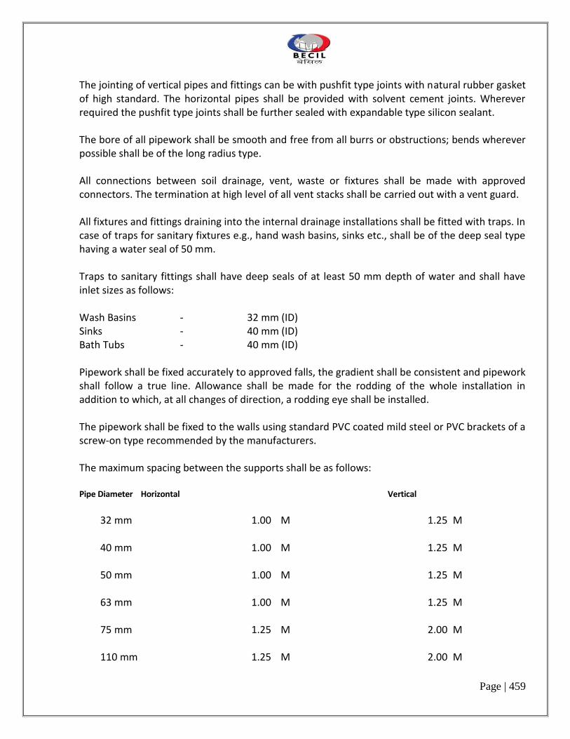
Page | 459
The jointing of vertical pipes and fittings can be with pushfit type joints with natural rubber gasket of high standard. The horizontal pipes shall be provided with solvent cement joints. Wherever required the pushfit type joints shall be further sealed with expandable type silicon sealant. The bore of all pipework shall be smooth and free from all burrs or obstructions; bends wherever possible shall be of the long radius type. All connections between soil drainage, vent, waste or fixtures shall be made with approved connectors. The termination at high level of all vent stacks shall be carried out with a vent guard.
All fixtures and fittings draining into the internal drainage installations shall be fitted with traps. In case of traps for sanitary fixtures e.g., hand wash basins, sinks etc., shall be of the deep seal type having a water seal of 50 mm.
Traps to sanitary fittings shall have deep seals of at least 50 mm depth of water and shall have inlet sizes as follows: Wash Basins - 32 mm (ID)
Sinks - 40 mm (ID) Bath Tubs - 40 mm (ID)
Pipework shall be fixed accurately to approved falls, the gradient shall be consistent and pipework shall follow a true line. Allowance shall be made for the rodding of the whole installation in addition to which, at all changes of direction, a rodding eye shall be installed.
The pipework shall be fixed to the walls using standard PVC coated mild steel or PVC brackets of a screw-on type recommended by the manufacturers. The maximum spacing between the supports shall be as follows:
Pipe Diameter Horizontal Vertical
32 mm 1.00 M 1.25 M
40 mm 1.00 M 1.25 M
50 mm 1.00 M 1.25 M 63 mm 1.00 M 1.25 M 75 mm 1.25 M 2.00 M 110 mm 1.25 M 2.00 M

Page | 460
163 mm 1.25 M 2.00 M
The Contractor shall provide access or rodding eyes wherever required to provide full access to the system. The rodding eye shall also be provided at the foot of all vertical stacks at the point of connection to the underground drain pipe.
Access doors in suspended pipework within 0.5 M of the sofit shall not face upwards but be located on the side or underneath the pipe.
Where traps, access branches and access doors are located above false ceiling, removable panels shall be provided.
Soil and waste ventilation pipes passing through roofs shall be weather proofed to the satisfaction of the Owner.
The vent pipes shall be carried upto a minimum height from finished roof level of 500 mm to prevent any pressure fluctuations in the stack due to wind effect.
Connections to the outlets of the water closets shall be made by the use of proprietary UPVC WC connectors. Generally vent and anti-syphonage pipes and fittings shall be installed above the flood level of the fitting wherever possible.
The whole of the installation shall be tested in accordance with the requirements of CPWD and Bureau of Indian Standards specification. All tests shall be to the full satisfaction of the Owner.
3.3.3 U.P.V.C. Floor Traps
Floor traps shall be UPVC deep seal type ‘P’ traps with a minimum seal of 50 mm. They shall be with or without vent as required.
3.3.4 U.P.V.C. Floor Trap Extension Piece
Wherever mentioned, floor trap shall be provided with UPVC extension piece. Length of the extension piece shall be as per the site conditions. Extension piece shall be formed out of boss pipe as per standard details and drawings.
3.4 CLEAN OUTS
Clean outs shall be provided in the soil, waste and vent pipework as per the standard details wherever shown on the drawings and wherever required by the Owner.

Page | 461
3.5 VENTILATION SYSTEM
i) Ventilating pipes shall project through walls or roofs to vent into the open air at the points shown on the drawings. The ventilation pipes shall be fitted with balloon at the top.
ii) No vent terminal shall be directly beneath any door, window or other ventilating openings
of the building, nor shall any such vent terminal be within 3 M horizontally of such an opening unless it is 60 cm above the top of such an opening.
iii) All vent and branch vent pipes shall be so graded and connected as to drip back to the soil or
waste pipe by gravity. Where vent pipes connect to horizontal soil or waste pipes, the vent pipes shall be taken off
above the centre line of the pipe. The vent pipes shall rise vertically or at an angle note more than 45o from the vertical to a point at least 150 mm above the floor level rim of the fixture it is venting before off-setting horizontally or before connecting to the branch vent.
v) A connection between a vent pipe and vent stack or stack vent shall made at least 150 mm
above the flood level rim of the highest fixtures served by the vent. Horizontal vent pipes forming branch vents, relief vents or loop vents shall be at least 150 mm above the flood level rim of the highest fixture served.
3.6 PIPE SLEEVES
The Contractor shall install sleeves for all piping passing through slabs, beams, walls or any other building member. The sleeves shall be fixed in formwork before pouring of concrete. In foundations and walls the sleeves shall be properly grouted and the gap between sleeve and building member shall be made water tight. All sleeves shall be of PVC.
3.7 FLASHINGS
Pipes extending through roof shall be flashed with sheet lead, copper or other durable material to make the roof water tight. Complete shop drawing of method of dressing, as may be required by the Owner, shall be submitted for his approval prior to installation. Alternatively, upstands with precast concrete slab covers shall be provided as per standard detail.
3.8.0 JOINTING OF NON-SIMILAR MATERIALS

Page | 462
3.8.1 UPVC & Cast Iron Pipes Wherever cast iron pipes and UPVC pipes are to be jointed, the spigot end of UPVC pipe shall be
jointed with socketed end of cast iron pipes. The length of spigot / plain end of UPVC pipe to be inserted in the socket of C.I. pipe shall be applied with PVC solvent cement and sprinklered with coarse sand end left for 24 hours. The joint shall be made with epoxy based (like Drip-Seal)
4.0 DOMESTIC WATER SERVICES
4.1 PIPE WORK
Where specified G.I. pipes for water supply inside and outside the building shall be genuine galvanised steel tubes conforming to IS:1239(Part-I)-1979 of specified grade with latest amendments. All fittings shall be malleable iron galvanised fittings conforming to IS:1879(Part-1 to 10)-1975 with latest amendments. All fittings shall have manufacturer's trade mark stamped on it. Fittings in G.I. pipe lines shall include elbows, tees, bends, reducers, nipples, union, bushes, G.I. clamps of approved design, G.I. flanges with 3 mm rubber insertion, nuts, bolts, washers, etc. All fittings shall be tested at manufacturer's work. Contractors may be required to produce certificate to this effect from the manufacturers. All pipework for water supply (both hot and cold) inside the building shall be carried out in a workmanship like manner following CPWD specifications in general. However the instead of white lead, thread lock cement shall be used for jointing the pipes and fittings. All materials shall be as specified in these specifications, bills of quantities and drawings. In case specifications of a material is not mentioned or not clear in the above, the reference shall be made to CPWD specifications and the relevant Indian Standards/codes.
CPVC PIPE WORK
Whereever specified, CPVC piping system for water supply system shall be SDR 11 rated and of approved makes. All pies and fittings shall comply with ASTM D 2846 standard.
All fittings shall be injection moulded. CPVC to CPVC jointing shall be fusion bonding type( Solvent Cement Type) using proprietary CPVC fusion compound. Transition fittings ( for making connections with valves, faucets, other appurtenances and non CPVC pipes) shall have brass insert having threads as per IS: 554. CPVC threaded fittings are not to be used.
All CPVC pipework for water supply (both hot and cold) inside the building shall be carried out in a workmanship like manner as per the manufacturer’s recommendations. All materials shall be as specified in these specifications, bills of quantities and drawings. All the brass threaded adaptors and specials shall be jointed properly using Teflon tape. For storage, cutting, jointing, installing and testing of CPVC material, manufacturer`s instructions shall be strictly adhered to.

Page | 463
Solvent Cement : The jointing of pipes and plain fittings shall be by solvant cement of make and grade as specified and supplied by the manufacturer of CPVC piping system. It shall be insured that the solvent supplied is not used beyond the expiry period as mentioned on the packaging of the material.
HORIZONTAL SUPPORTS SPACING:
DIA
SPACING IN METRE AT WORKING TEMPERATURE
230 C 380 C 600 C 820 C
½ “ 1.22 M 1.07 M 1.07 M 0.92 M
¾” 1.53 M 1.37 M 1.22 M 0.92 M
1” 1.68 M 1.53 M 1.37 M 0.92 M
1 ¼” 1.83 M 1.68 M 1.53 M 1.22 M
1 ½” 1.98 M 1.83 M 1.68 M 1.22 M
2” 2.29 M 2.14 M 1.98 M 1.22 M
Curing Time: After the CPVC installation is completed, adequate time as per following schedule shall be provided for the curing of the of the joints before subjecting the system to pressure testing or putting it to use:
Ambient Temperature Pipe Sizes
½’ – 1 ¼”
Pipe Sizes
1 ½”– 2”
Above 160 C ½ hr. 1hr.
From 50 C – 160 C 1hr. 2hr.
Below 50 C 3hr. 6hr.
4.2.0 INSULATION OF HOT WATER PIPES
4.2.1 Synthetic Rubber Polymeric Compound Insulation

Page | 464
The hot water supply pipes shall be insulated with extended Synthetic Rubber Polymeric Compound, pre-formed pipes sleeves, if directed by the engineer incharge. The pipes sleeves shall be fixed using propriety adhesive and self adhesive tapes, all as per the manufacturer’s specifications.
4.3 VALVES, TAPS AND MIXERS
4.3.1 General
Each valvebody shall be marked with cast or stamped lettering giving the following informations :
a) The manufacturer’s name or trade mark b) The size of the valve c) The guaranteed working pressure
Isolating valves on the water supply lines shall be full bore ball valve type for pipe diameters upto 50 mm. For 65 mm dia and 80 mm dia., these shall be gate valve type and diameters above 80 mm, `these shall be sluice valve type.
4.3.2 Float Valve
Float valves 50 mm and smaller shall be of brass, gun metal or other equally suitable corrosion resistant alloy
in accordance with IS:1703-1977 or approved equal. The float valves shall have copper or plastic floats suitably
reinforced to hold the threaded insert. The float valves fixed to the system shall be secured with backnuts.
4.3.3 Fullway Gate Valve
The valves shall be of quality approved by the Consultant/Owner and shall generally conform to IS:778-1971.
4.3.4 Full Way Ball Valve
The valves shall be of full bore type and of quality approved by the Consultant/Owner. The body and ball shall be of copper alloy and stem seat shall be of teflon.
4.3.5 Non-Return Valves
Non-return valves are to be IS:778-1984 manufactured from gun-metal or dezincification resistant brass.
4.3.6 Pressure Reducing Valve

Page | 465
The valve shall be suitable for water application and shall conform to relevant BIS standard. The valve should be installed in a vertical portion on horizontal line. In all cases, a stop valve should be installed in an easily accessible position on the inlet side of the pressure reducing valve. A safety valve and a pressure gauge must always be installed on the reduced pressure or outlet side of the pressure reducing valve. To avoid any dirt from entering the valve, it is advisable to fit a strainer on the inlet or high pressure line. The pressure reducing valve and accessories should conform to relevant BIS standard and of approved make.
4.3.7 Butterfly Valves
The valve shall of cast iron conforming to relevant IS:13095. The valve shall be of quality approved by the
consultant/Owner.
4.3.8 Taps and Mixers
Bib or mixer taps shall be fixed to sinks, lavatory basins, bathtubs and showers and as shown on the drawings and/or specified under the Sanitaryware schedule.
The Contractor must ensure that the installed taps and mixers are not damaged or mishandled till the handing over of the installation.
5.0 SANITARY FIXTURES AND FITTINGS
5.1 WORKMANSHIP
All Sanitaryware shall be fixed in neat workmanship like manner, true to level and plumb. Manufacturer's instructions shall be followed closely regarding installation and commissioning.
5.2 SANITARYWARE
All sanitaryware, shall be of approved make. All fittings shall be of first quality, free from wraps, cracks and glazing defects. All sanitaryware, fittings and fixtures shall be as shown in drawings and as described in details in schedule of quantities.
5.3 FIXING
All sanitarywares shall be installed in accordance with manufacturers printed instructions for conditions indicated and as required to obtain a rigid installation. The location of each fixture and the fixing method of ceramic fixtures shall be as shown on the drawings or as directed by the Owner.

Page | 466
After all fittings have been mounted and are ready for use and before completion, all fittings furnished and mounted shall be thoroughly cleaned removing all plaster, stickers, rust, hair and other foreign matter or discolouration of fixtures, leaving each and every part in perfect condition and ready for use.
5.4 PROTECTION
The Contractor shall take adequate precautions to ensure that the sanitarywares are not damaged in any way before or after installation. Any piece of sanitaryware that is damaged shall be replaced at the Contractor's expense. The Contractor shall be responsible for checking sanitaryware on arrival at site. If any pieces of sanitarywares are found to be damaged on arrival at site, the Contractor shall inform the Owner within two days. If the sanitarywares are delivered in damaged state, the Contractor shall refuse delivery of the damaged piece and shall request a replacement of the same.
5.5 TESTING
Just prior to handing over the building to the Owner, each piece of sanitaryware shall be tested. Each water closet shall be flushed twice and checked for leaks and any other defects by the Owner.
Each basin, bidet, bath and sink shall be filled to the overflow level and then after running the
water through the overflow for a minimum of 30 seconds, the plug shall be removed or opened. Each of the above mentioned fixtures shall be inspected for leaks and defects by the Owner.
Any defects or leaks shall be repaired or in the case of the defect being chips or cracks or other
visible damage, the fixture shall be replaced at the Contractor's expense. Any sanitaryware condemned by the Owner for any other reason shall be replaced at the Contractor's expense.
6.0 FIRE FIGHTING INSTALLATION
6.1.0 PIPE WORK 6.1.1 Materials
The pipe work shall be done in black mild steel pipes of `Heavy’ grade conforming to IS:1239 (Part I)-1990 for upto 150 mm dia pipe and IS:3589-1991 for pipes above 150 mm dia. Fittings: All fittings upto 50 mm dia shall be black forged steel pipe fittings with threaded ends/ weldable socketed ends. Fittings above 50 mm dia shall be heavy duty mild steel with weldable ends. All fittings shall be conforming to relevant Indian Standards and shall have manufacturer's

Page | 467
trade mark stamped on it. Fittings in M.S. pipe lines shall include elbows, tees, bends, reducers, nipples, union For welded joints forged steel fittings of approved type with “V” groove shall be used. Fabricated fittings shall not be permitted generally. However, if use of any fabricated fitting is found necessary by the Project Manager, fabrication of such fitting shall be taken up by the Contractor on the written directives of the Project Manager in a workshop following proper welding procedures. For fabricating a ‘Tee’ connection pipes shall be drilled and reamed and joint only welded. Gas cutting of pipes shall not be permitted. Fabricated ‘Tee’ out of M.S. plates shall not be used. All fittings shall be tested at manufacturer's work. The Contractor may be required to produce certificate to this effect from the manufacturers. .
6.1.2 Jointing
The pipes and fittings upto 50 mm diameter shall be threaded joints using thread lock cement on the threads.
Joints for pipe and fittings above 50 mm diameter shall be welded joints. Care shall be taken to remove any burr
from the end of the pipe after cutting..
Welded Joints
General
The welding of pipes in the field should comply with IS:816, 1969. Electrodes used for welding should comply with IS:814, 1991.
Joints between M.S. pipes and fittings shall be made with pipes and fittings having “V” groove and welded with electrical resistance welding in an approved manner Butt welded joints shall not be acceptable. Care shall be taken to remove any burr from the end of the pipe after cutting. All welders must be fully qualified and proof of an operator’s qualification shall be either the Contractor’s record of suitable tests passed within the previous six months or tests made before the commencement of the work. The Contractor must submit to the Owner the names of the welders who will be employed on the work, together with documentary evidence of their competency. Any welder considered by the Owner as not having the skill necessary for the work will at once be barred from further welding on the site or in the Contractor’s workshop. The Owner may instruct the Contractor to cut out typical welded joints for inspection and the Contractor shall include for the removal of such pieces and re-making joints to the satisfaction of

Page | 468
the Owner. The Contractor shall include in his Tender for the cost of removing all such pieces for inspection and re-making joints. Care must be exercised by the Contractor to ensure that the welding flux does not project into the bore of the tube. All welds shall be good, clean metal, free from slag inclusions and porosity, of even thickness and regular contour, well fused with the parent metal and finished smooth. Where site welding is carried out in proximity to inflammable materials, the Contractor must take special precautions to protect the materials from risks of fire.
Testing of Welded Joints
The welded joints shall be tested in accordance with procedure laid down in IS:3600 (Part I) : 1985. One test specimen taken from at least one field joint out of any 10 shall be subjected to test. If the results of the tensile test do not conform to the requirements specified, retests of two additional specimen from the same section shall be made, each of which shall conform to the required specifications. In case of failure of one or two, extensive gouging (scooping out) and repairing shall be carried out as directed by the authority. If internal pressures exceed 1.5 MPa (15 kgf/cm2), special attention should be given to the assembly of the pipe and the first run of weld. Non-destructive testing of the completed weld may be carried out on pipe-lines by radiographic (see IS:4853 : 1982) or ultrasonic method (see IS:4260, 1986)) as agreed upon between the Owner and the Contractor.
Screwed Joints
Joint for black steel pipes and fittings shall be metal to metal threaded joints using Teflon tape on the threads.
Flanged Joint
M. S. Flanges shall be as per IS: 6392 and shall be faced. Rubber or asbestos gasket shall be inserted between
the joints.
Flange shall be provided on : a) Straight runs not exceeding 12-15 m on pipe lines 80 mm dia and above. b) Both ends of any fabricated fittings e.g. bends, tees etc. of 65mm or larger diameter. c) For jointing all type of valve, appurtenances, pumps, connection with other type of pipes, to
water tanks and other places necessary and required as per good for engineering practice.

Page | 469
Unions
Provide approved type of dismountable unions on pipes lines 65 mm and below in similar places as specified for flanges.
6.2 LAYING AND FIXING
a) Above Ground :
Exposed pipes on walls and ceilings shall be fixed with standard pattern G.I. holder bat clamps on angle iron frames embedded in walls or suspended from ceiling. The clamps shall be spaced at regular intervals in straight lengths as per the following table :-
Dia of Pipe Horizontal Length Vertical Length (mm) (M) (M)
25 2.4 3.0 32 2.7 3.0 40 3.0 3.6 50 3.0 3.6 65 3.6 4.5 80 3.6 4.5 100 4.0 4.5 150 4.5 5.4
b) Under Ground:
The trenches for the underground mains shall be 75 cm wide at top and excavated to a depth so that a minimum 1 meter of cover above the crown of the pipe is available after backfilling.
The pipes shall be evenly laid in the trenches after coating and wrapping as described hereinafter and covered with fine sand 150 mm all around. Any damage to coating and wrapping shall be made good before backfilling.
c) Protection of Underground Pipes:
The underground steel pipes shall be protected by coating and wrapping. The coating and wrapping shall be done, in general, as per IS:10221 - 1982.
First of all the pipes surface shall be roughly cleaned and dried before the application of primer, and shall be free of dirt, grease, oil, rust, scale or other foreign matter. After cleaning one uniform coat of coal tar primer shall be applied on the surface and one layer of glass fibre tissue shall be wrapped and simultaneously hot coat tar shall be applied. On this another layer

Page | 470
of glass fibre tissue saturated with coal tar shall be wrapped with the simultaneous application of coal tar.
d) Anchor Blocks
Suitably designed anchor blocks in cement concrete to encounter excess thrust due to water hamer and high pressure should be provided at all bends, tees and such other locations as directed by the Engineer-in-charge. Exact location, design, size and mix of the concrete block shall be approved by the Architect / Consultant prior to the execution of the work.
6.3 VALVES
GENERAL
Each valve body shall be marked with cast or stamped lettering giving the following informations
a) The manufacturer’s name or trade mark b) The size of the valve c) The guaranteed working pressure
Isolating valves on the water supply lines shall be full bore ball valve type for pipe diameters upto 50 mm. For
65 mm dia and above these shall be butterfly valves.
6.3.1 Full Way Ball Valve
The valves shall be of full bore type and of quality approved by the Consultant/Owner. The body and ball shall
be of copper alloy and stem seat shall be of teflon.
6.3.2 Butterfly Valves
The valve shall of cast iron conforming to relevant IS:13095. The valve shall be of quality approved by the consultant/Owner.
6.3.3 Non-Return Valves
The valves shall be of quality approved by the Project Manager and shall generally conform to IS:778 - 1971.
6.3.4 Full Way Gate Valve

Page | 471
The full way valves shall be either of full bore brass ball valve or of heavy gunmetal conforming to IS:778 -
1984.
6.3.5 Air Relief Valve
Air Valves are to be provided on all high points in the system. These shall be 25 mm dia screwed inlet cast iron single acting air valves.
6.3.6 DRAIN VALVE
Drain Valves are to be provided at all low points in the system for draining the water. These shall be 40 mm dia gun metal full way valve fixed on 40 mm dia black steel pipe.
6.3.7 PRESSURE SWITCHES
Pressure Switches shall be differential type for operation of all pumps and for the various duties and settings required. Pressure switches shall be for heavy duty operation and of approved make. All pressure switches shall be factory calibrated.
6.4.0 FIRE FIGHTING APPARATUS & FITTINGS
6.4.1 Internal Hydrants (Landing Valves)
i. The internal hydrant shall be single headed gunmetal landing valve with 63 mm dia
outlet and 80 mm inlet (I.S:5290-1969), with individual shut off valves and cast iron wheels. Landing valve shall have flanged inlet and instantaneous type outlets as shown on the drawings.
ii. Instantaneous outlets for fire hydrants shall be of standard pattern approved and
suitable for fire brigade hoses.
iii. Contractor shall provide for each internal fire hydrant station two numbers of 63 mm dia. 15 mm long rubberised fabric linen hose pipes with gunmetal male and female instantaneous type coupling machine wound with G.I. wire (hose to I.S:636 type 2 and couplings to I.S:903 with I.S certification), fire hose reel, gunmetal branch pipe with nozzle I.S:903.
6.4.2 First Aid Fire Hose Reel The First Aid Fire Hose Reels must be of type II and shall have 30 metre of 20 mm dia bore
reinforced rubber hose fitted with shut-off gun metal nozzle. The hose reel shall be conforming to IS:884 - 1985.
6.4.3 Fire Hose Cabinet

Page | 472
The Fire Hose Cabinet of sizes suitable to accommodate equipment as specified in bill of
quantities shall be fabricated of 16 gauge CRCA M.S. sheet and painted in fire red colour. Its door shall be hinged type having lock and reinforced glass panel.
The fire hose cabinet for yard hydrants shall be weatherproof type of size suitable to accommodate 2 nos. of
15M long 63mm diameter R.R.L. hoses with female & male gunmetal coupling and branch pipes.
Wherever masonry shaft is available to house equipment, only the glazed front panel is to be
fixed as required and as specified in bill of quantities. 6.4.4 SPRINKLER HEADS
Sprinkler heads shall be of gunmetal and quartz bulb type with a temperature rating of 68 deg. Centigrade or
as specified in the bill of quantities. These shall be of type and quality approved by the local fire service and TAC.
6.5.0 AUTOMATIC SPRINKLER SYSTEM 6.5.1 Scope
The scope involves taping from existing riser and distribution of piping system shall be made as per the drawing

Page | 473
7.0 TESTING AND COMMISSIONING
7.1 GENERAL The Contractor shall be responsible for testing and commissioning the entire services installation
described in these specifications and will demonstrate the operation of the system of the entire satisfaction of the Architect/Consultant and to the Owner approval. Work under this section shall be executed without any additional cost. The rates quoted in this tender shall be inclusive of the works given in this section. Contractor shall provide all tools, equipment, metering and testing devices required for the purposes. The entire fire fighting piping system shall be tested at minimum 14 kg/cm2 pressure. The test pressure shall the maintained for at least 2 hrs
. 7.2 METHOD OF TESTING The test on various services shall be carried out as described herein as described in relevant
Indiant Standards and British Standards and also as directed by the Owner. The carrying out and recording of tests shall be agreed with the Architect/Consultant. 7.3 WATER FOR TESTING Water for testing shall be obtained by the Contractor from an approved source. It shall be free
from bacterial contamination, silt, grit, sand etc. After testing, the Contractor shall satisfactorily dispose off all water, or it may be re used providing it is clean and is not contaminated.
7.4 TEST RECORDS
The Contractor shall be responsible for the keeping all records of tests and on completion shall provide records and reports of the tests in triplicate. All test records shall clearly identify the item of the test and must be signed by the Contractor’s authorised representative and Owner.
7.5 UNSATISFACTORY WORKS If the tests reveal unsatisfactory materials, installation or adjustment, the Contractor shall, at his
own expense, carry out such alternations or replacements as may be necessary to rectify the defective work. The Contractor shall then repeat the tests as necessary to establish the satisfactory nature of the alterations or replacements.

Page | 474
7.6 TESTING AT WORKS All plants and equipments shall be tested at manufacturer’s works before despatch and the test
certificate in duplicate shall be forward to Architect/Consultant.
The Contractor shall similarly provide a set of manufacturer's certified test curves for any pump installed under the Contract. All tests shall be in accordance with the appropriate Indian Standards and British Standards as applicable.
7.7 ON SITE TESTING
The Contractor shall provide on site all the necessary instruments, plant, equipment, materials, water, electricity and labour necessary for carrying out the specified tests. All tests shall be carried out as required to meet the construction programme and the Contractor shall include for all necessary isolation and other works as may be required for testing the whole or parts of the installation. The Contractor shall also be responsible for re-testing, if necessary, until satisfactory tests are achieved.
7.8 TEST P RESSURES
Pipe Line Test Pressure Period Method
Water Mains, Fire Mains & Water Services.
5 kg/sq.cm. or maximum working pressure plus 50 percent which ever is greater.
2 Hours Hydraulic Pressure Test
Underground Drainage
1.5 metres head of water at highest point
30 min. Hydraulic Test
Foul Drainage above ground
i) Not more than 4.5 M head in any section
2 Hours Hydraulic Test
ii) 75 mm water gauge 3 min. Air Test
7.9.0 TESTING OF VARIOUS SERVICES
7.9.1 Water Services
Before the pipes for water supply are painted or covered they shall be tested to a hydraulic pressure of 5
kg/sq.cm or maximum working pressure plus 50 percent whichever is greater. Pressure shall be maintained for
atleast 2 hours without appreciable drop in pressure. In addition to the sectional testing of water supply pipes,

Page | 475
the Contractor shall test the entire installation on completion of the job to the entire satisfaction of the
Owner. The Contractor shall rectify all leakages and restore damage done to the building and furniture at his
own cost.
7.9.2 Underground Drainage
The sewer and drain lines shall be tested for water tightness and straghtness as described below
i) Water Test: Pipes and joints shall be subjected to a test pressure of atleast 1.5 m head of water at the
highest point of the section under test. The test shall be carried out by suitably plugging the low end of the drain and filling the system with water. A knuckle bend shall be temporarily jointed in at the top end and a sufficient length of vertical pipe jointed to it so as to provide the required head. Or top end may be plugged with a connection to a hose ending in a funnel which could be raised or lowered till the required head is obtained and fixed suitably for observation.
ii) Test for Straightness and Observation. Sewer lines shall be tested for straightness :
a) By inserting at the high end of the sewer or drain a smooth ball of diameter 13 mm less than the pipe bore. In the basence of obstruction, such as yam or mortar projecting through the joints, the ball should roll down the invert of the pipe and emerge at the lower end; and
b) By means of a mirror at one end of the line and lamp at the other. If the pipe line is
straight, the full circle of light can be observed. If the pipeline is not straight, this will be apparent. The mirror will also indicate obstruction in the barrel.
7.9.3 Above Ground Foul Drainage
All soil, waste and vent pipes shall be tested by filling up the whole or part of stack with water. All openings for
connections, etc. shall be suitably plugged. The total head shall however not exceed 4.5 metres.
Contractor shall remove and replace all pipes having holes, cracks etc. All leaking joints and access doors shall be replaced or remade to the entire satisfaction of the consultant. Water shall be retained in stack for a minimum period of 2

Page | 476
hours. After all plumbing fixtures are installed. Contractors shall apply the smoke test to the entire stack to the satisfaction of the Consultant.
7.9.4 Sanitary Fixtures & Fittings
When the installation has been complete to the satisfaction of the Consultant, it shall be tested in the
following manner :
i) The entire system shall be slowly filled with water, allowing any trapped air to escape. ii) When all outlets are closed, the system shall be checked for water tightness. iii) Each outlet shall then be checked for rate of flow and correct operation. iv) Waste outlets of wash basins and sinks shall be plugged and the basin and sink bowls shall
be filled upto over flow level. Plug shall be removed and waste pipe and trap shall be checked for leakage and floor drain (if fixture waste is connected to floor drain) shall be checked for overflow.
7.9.5 Testing Manholes
All open channel manholes shall be tested with water to a height of 1 metre above the channel invert or as
otherwise directed. The water level shall be retained for a 2 hour period without appreciable loss. When the
water is released the benching shall be inspected to ensure that there are no cracks
7.9.6 FLUSHING OUT AND STERILISATION OF PIPEWORK AND TANKS
It is essential that all internal water services, external mains and tanks are thoroughly flushed out prior to
being put into service and that drinking and domestic water services mains and tanks are sterilised in
accordance with clause 13 of IS : 2065-1983 – Code of Practice for Water Supply in Buildings.
The Contractor shall be responsible for making any temporary pipe work connections required.
Following completion of sterilisation of every part of the drinking and domestic water system, the Contractor is to ensure that satisfactory bacteriological samples are obtained and tested at an

Page | 477
approved laboratory and the result approved by the Architect/Consultant prior to completion of the contract and handing over to the Owner.
7.10 IDENTIFICATION OF PIPES LINES
All pipeline installation shall be provided with a colour identification system. The system in general shall be as per IS:2379-1983-Specification of Colour Code for the Identification of Pipe Lines. The colour identification system shall comprise of : a) Basic Identification Colour over the whole length of pipe b) Code indication bands for precise determination of the contents being carried by the pipe The code indication bands shall be minimum 150mm wide and shall be placed at all junctions, at both sides of valves, service appliances, bulk heads, wall penetrations and at any other place where identification is necessary. The colour of code indication bands shall be as directed by the Employer/Architect.
8.0 PREAMBLE TO THE PRICING OF BILL OF QUANTITIES
8.1 GENERAL 1. This section shall be applicable for item rate work and for variations. 2. This preamble covers installation of sewerage, drainage, external & internal water supply and
sanitary installation works. 3. This preamble shall be read in conjunction with the Specifications, Conditions of Contract and all
other documents accompanying the tender papers. 4. For all items of work the rates shall be comprehensive and all inclusive. The rates shall include for
all materials and things necessary for satisfactory completion and maintenance of the work in proper working order and to the satisfaction of the Architect/Consultant, including testing, making samples etc., and all that have been indicated in the Specifications or other Tender Documents either directly or indirectly and cover for all obligations of the Contractor under the Contract. No claim for additional payment shall be allowed for any error or misunderstanding by the Contractor of the work involved.
5. Unless otherwise mentioned in the description of the item, this Schedule shall be applicable for
work at any height, position or condition.

Page | 478
6. Unless otherwise stated, method of ‘measurement' as described in the latest ‘Specifications' of CPWD shall be followed. In case of any dispute in this regard, the Architect's decision shall be final, binding and conclusive.
7. The following notations have been used throughout the Schedule of Quantities and Rates :
m/M Running Metre
Sqm Square Metre Cum Cubic Metre mm/MM Millimeter No. Number/Numbers Dia. Diameter Kg. Kilogram/s T. Tonne L.S. Lump Sum Pt. Point Rs. Indian Rupees ND Nominal internal Diameter of pipe (mm) % Percent. 8.2 TRADE PREAMBLE 1. Pipe work SOIL, WASTE AND VENTILATION PIPEWORK
a) Pipework is to be measured in running meters nearest to a cm as fixed or laid. The length shall be taken along the center line of the pipes over all the fittings, such as bends, tees, junctions, all with or without doors, door pieces, cowls, etc. which shall not be measured separately.
b) The rate shall be include the cost of materials and
labour involved in supplying, fixing with

Page | 479
holder bats & MS stays, laying underground, cutting holes, chases in walls, floors and painting with two or more coats of paint of approved quality and shade.
c) Floor Traps Floor traps shall be measured by number. The
rate shall be inclusive of supplying of trap and grating, setting, in concrete and connecting branch pipes to it.
G. I. PIPES FOR WATER SUPPLY (EXTERNAL) a) Pipe work is to be measured in running
meters nearest to a cm for the finished work, which shall include G.I. fittings such as bends, tees, elbows, reducers, crosses, plugs, sockets, nipples and nuts but shall exclude brass or ornamental taps, valves, etc.
b) The rate shall be inclusive of the cost of
materials and labour, excavation and earth work.
G. I. PIPES FOR WATER SUPPLY (INTERNAL). a) As a) above. b) The rate shall be inclusive of cost of materials
and labour, cutting holes and chasing in walls and floors and making good the same, providing sleeves, applying anti-corrosive paint and 0.2mm thick PVC on buried and concealed pipe work and painting of exposed pipes.
c) The rate shall be inclusive of providing
‘Identification and Labeling’ of pipes with the colour coded bands.
d) Insulation of hot water pipes shall be paid
separately.

Page | 480
3. Valves, cocks and other Appurtenances Appurtenances like valves, water meter etc. shall be measured in number. Rates hall include -
a) testing and checking of appurtenances and fittings before taking delivery of the same.
b) delivering the appurtenances to the specified
storage area at site; c) lowering the same into specified support
(including providing the support) jointing, fitting and fixing true to line and level including repairing of protective coating, if necessary; and
d) providing all equipment labour and materials
necessary to carry out the above works complete in all respect as specified and/or instructed.
e) Insulation of valves shall be paid separately. 4. Sanitary Fixtures & Faucets All sanitary fixtures and faucets of specified
trade mark or equivalent shall be paid by number. The rate shall include fixing components, brackets, screws and any other specials required, cutting holes in walls and making good the same.
The rate shall also be inclusive of painting R.S.
or M.S. brackets for cisterns, wash basin, sinks etc. with one coat of red oxide and two coats of epoxy paint of approved shade and quality.

Page | 481
9. LIST OF APPROVED MAKES/MANUFACTURES OF MATERIALS
NOTE : All Brand Names/Manufacturers are Indian unless specified otherwise.
I SANITARY PLUMBING INSTALLATION
S.NO. MATERIAL BRANDNAME / MANUFACTURER
A. Sanitary Fixtures and Faucets
1 Vitreous China Sanitaryware a) American Standard b) Roca 2. C.P. brass Faucets, Wastes, Traps etc a) Kohler b) Jaquar 3. C.P. Wastes, Spreaders, Urinal Flush Pipe a) Lotus b) Orient c) ESS ESS 4. Concealed Cistern a) Viega b) Geberit 5. Infrared Sensor operated Faucets a) Euronics b) Kohler c) Utec d) Jaquar 6. C.P. Angle Valves (Ball Valve Type) a) Schell b) ARCO, Spain 7. Stainless Steel Sink a) Nirali b) Jayna b) Neelkanth 8. Geyser a) Racold b) AO Smith 9. Automatic Hand Dryer a) Euronics b) Utec c) Kohler

Page | 482
d) Kimberley Clark 10. Towel Paper Dispenser a) Euronics b) Utec d) Kimberley Clark 11. Automatic Soap Dispenser a) Euronics b) Kohler c) Utech d) Kimberley Clark
S.NO. MATERIAL BRANDNAME / MANUFACTURER
B. Pipes and0Fittings
1. Centrifugally Cast (Spun) Iron Soil, Waste & Vent Pipes a) Jayaswal Neco and Fittings ( Nagpur)
2. UPVC Pipes and Fittings a) Supreme b) Prince 3. CPVC Pipes and Fittings a) Astral b) Ashirvad
4. G.I. Pipes a) Tata b) Jindal, Hissar 5. G.I. Fittings a) Unik Brand
6. Gratings, Strainers, Cleanouts etc. a) GMGR b) Neer
C. Insulation
1. closed cell chemically cross-linked polyethylene a) Thermaflex ( XLPE) preformed pipe sleeves insulation

Page | 483
D. Valves
1. Ball Valves a) ARCO, Spain b) CIM, Italy c) Tieamy, Italy 2. Butterfly Valves a) Audco
b) Advance c) Danfoss
E Plant & Equipment
1. Packaged Hydropneomatic Systems a) Grundfos, Denmark ( Factory Fitted) b) DP, Holland c) Wilo, France
2. FRP Vessel a) Pentair
b) Aventura
E. Miscellaneous Items
1. Stainless steel tank a) Neropure 2. Stainless steel braided flexible connection pipe a) Schell, Germany b) ASR, Italy (Marketed by Deepak Exim Company)
S.NO. MATERIAL BRANDNAME / MANUFACTURER
3. Expansion Bolts a) Hilti b) Canon 4. G.I. Hangers for Pipes / Adjustable Hanger a) Chilly b) GMGR
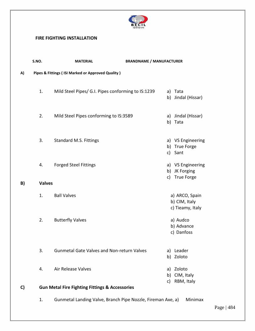
Page | 484
FIRE FIGHTING INSTALLATION
S.NO. MATERIAL BRANDNAME / MANUFACTURER
A) Pipes & Fittings ( ISI Marked or Approved Quality )
1. Mild Steel Pipes/ G.I. Pipes conforming to IS:1239 a) Tata b) Jindal (Hissar)
2. Mild Steel Pipes conforming to IS:3589 a) Jindal (Hissar) b) Tata
3. Standard M.S. Fittings a) VS Engineering b) True Forge c) Sant 4. Forged Steel Fittings a) VS Engineering b) JK Forging c) True Forge
B) Valves 1. Ball Valves a) ARCO, Spain b) CIM, Italy c) Tieamy, Italy 2. Butterfly Valves a) Audco
b) Advance c) Danfoss
3. Gunmetal Gate Valves and Non-return Valves a) Leader b) Zoloto 4. Air Release Valves a) Zoloto b) CIM, Italy c) RBM, Italy
C) Gun Metal Fire Fighting Fittings & Accessories 1. Gunmetal Landing Valve, Branch Pipe Nozzle, Fireman Axe, a) Minimax

Page | 485
Fire Brigade Connection, Male-Female Couplings etc. b) Newage (ISI Marked)
D) Sprinkler Heads & Installations Valves
1. Quartozoid Bulb type Sprinkler Heads a) Tyco ( UL and FM Approved) b) Viking 2. Flexible Sprinkler Drops a) Viking ( UL and FM Approved) b) Victaulic 3. Sprinkler Rosette Plate a) Tyco ( UL Listed) b) Viking
F) Paint / Primer a) Shalimar
b) Asian c) Nerolac G) Fire Extinguishers
1. Portable Fire Extinguishers a) Ceasefire b) Kanex
K) Miscellaneous 1. Expansion Bolts a) Hilti b) Fisher c) Canon 2. Flow Switches a) Spraysafe b) System Sensor,U.S.A 3. G.I. Hangers for Pipes / Adjustable Hanger a) Chilly b) GMGR

Page | 486
4. Welding Rods a) Advani b) Esab 5. Pressure Gauges a) H Guru b) Fiebig
Note : The Contractor shall provide the materials as per the MAKE or BRAND indicated above. When two or more alternative brands have been mentioned, the brand to be finally used shall be as decided by the Consultant/ Project Manager
DETAILED ELECTRICAL POWER & WATER REQUIREMENT FOR HVAC SYSTEM – PROPOSED OFFICE SPACES FOR EMMC AT SOOCHNA BHAWAN, NEW DELHI (As on 11th March’16)-R0
ELECTRICAL POWER REQUIREMENT
Floor/Space Equipment Selection (Nominal Capacity)
Electrical Power Requirement
Power Characteristics
Remarks
11th Floor
Hall-04 2x8.5TR & 1x5.5TR Conventional type ductable split units
2x11.9KW =23.8KW & 1x7.7KW
415 V/3 Ph Power cable along with earthing to be provided at each Outdoor Unit
Hall-03 2x8.5TR Conventional type ductable split units
2x11.9KW =23.8KW
415 V/3 Ph Power cable along with earthing to be provided at each Outdoor Unit
Hall-02 1x8.5TR & 1x5.5TR Conventional type ductable split units
1x11.9KW & 1x7.7KW
415 V/3 Ph Power cable along with earthing to be provided at each Outdoor Unit
Director Cabin 1x4.0TR Conventional type ductable split unit
1x5.6KW
415 V/3 Ph Power cable along with earthing to be provided at Outdoor Unit
Deputy Director-3 1x2.0TR Hi-wall split unit
1x2.8KW
220 V/I Ph Power Point to be provided at outdoor unit
2 Staff Members adjoining Deputy Director-3
1x1.5TR Hi-wall split unit
1x2.1KW
220 V/I Ph Power Point to be provided at outdoor unit
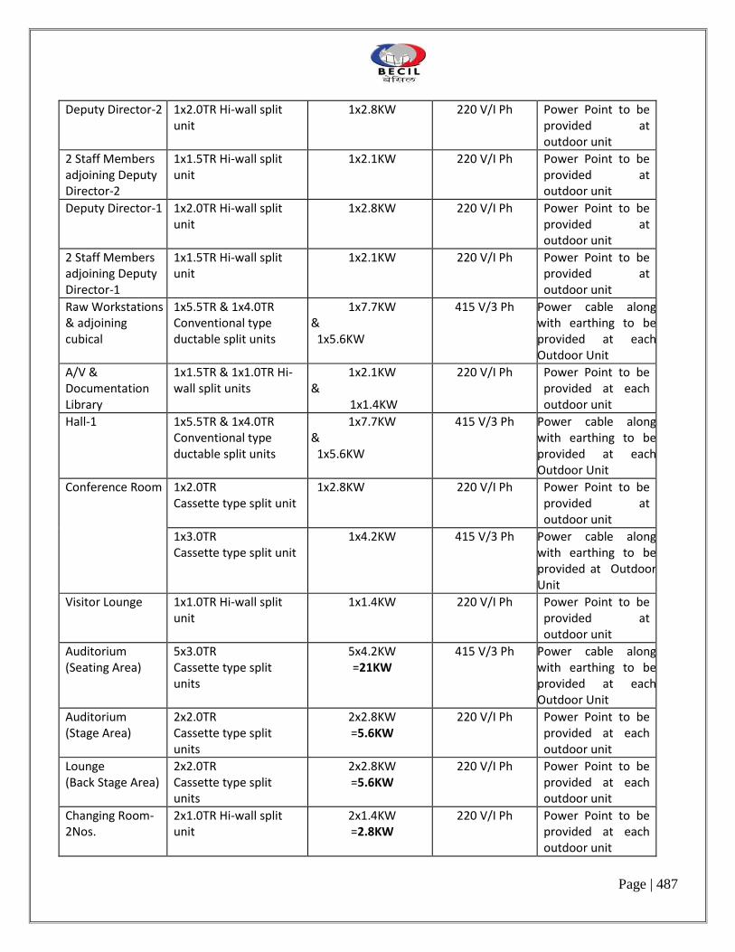
Page | 487
Deputy Director-2 1x2.0TR Hi-wall split unit
1x2.8KW
220 V/I Ph Power Point to be provided at outdoor unit
2 Staff Members adjoining Deputy Director-2
1x1.5TR Hi-wall split unit
1x2.1KW
220 V/I Ph Power Point to be provided at outdoor unit
Deputy Director-1 1x2.0TR Hi-wall split unit
1x2.8KW
220 V/I Ph Power Point to be provided at outdoor unit
2 Staff Members adjoining Deputy Director-1
1x1.5TR Hi-wall split unit
1x2.1KW
220 V/I Ph Power Point to be provided at outdoor unit
Raw Workstations & adjoining cubical
1x5.5TR & 1x4.0TR Conventional type ductable split units
1x7.7KW & 1x5.6KW
415 V/3 Ph Power cable along with earthing to be provided at each Outdoor Unit
A/V & Documentation Library
1x1.5TR & 1x1.0TR Hi-wall split units
1x2.1KW &
1x1.4KW
220 V/I Ph Power Point to be provided at each outdoor unit
Hall-1 1x5.5TR & 1x4.0TR Conventional type ductable split units
1x7.7KW & 1x5.6KW
415 V/3 Ph Power cable along with earthing to be provided at each Outdoor Unit
Conference Room 1x2.0TR Cassette type split unit
1x2.8KW 220 V/I Ph Power Point to be provided at outdoor unit
1x3.0TR Cassette type split unit
1x4.2KW
415 V/3 Ph Power cable along with earthing to be provided at Outdoor Unit
Visitor Lounge 1x1.0TR Hi-wall split unit
1x1.4KW
220 V/I Ph Power Point to be provided at outdoor unit
Auditorium (Seating Area)
5x3.0TR Cassette type split units
5x4.2KW =21KW
415 V/3 Ph Power cable along with earthing to be provided at each Outdoor Unit
Auditorium (Stage Area)
2x2.0TR Cassette type split units
2x2.8KW =5.6KW
220 V/I Ph Power Point to be provided at each outdoor unit
Lounge (Back Stage Area)
2x2.0TR Cassette type split units
2x2.8KW =5.6KW
220 V/I Ph Power Point to be provided at each outdoor unit
Changing Room-2Nos.
2x1.0TR Hi-wall split unit
2x1.4KW =2.8KW
220 V/I Ph Power Point to be provided at each outdoor unit

Page | 488
Make-up Room 1x1.0TR Hi-wall split unit
1x1.4KW
220 V/I Ph Power Point to be provided at outdoor unit
Guard & seating bench area
1x1.5TR & 1x1.0TR Hi-wall split units
1x2.1KW &
1x1.4KW
220 V/I Ph Power Point to be provided at each outdoor unit
Cafeteria 4x3.0TR Cassette type split units
4x4.2KW =16.8KW
415 V/3 Ph Power cable along with earthing to be provided at each Outdoor Unit
1x2.0TR Cassette type split units
1x2.8KW 220 V/I Ph Power Point to be provided at outdoor unit
Recreational Area 2x1.5TR Hi-wall split unit
2x2.1KW =4.2KW
220 V/I Ph Power Point to be provided at each outdoor unit
Medical 1x1.5TR & 1x1.0TR Hi-wall split units
1x2.1KW &
1x1.4KW
220 V/I Ph Power Point to be provided at each outdoor unit
Hindi Cell, RTI Cell & Legal Cell
1x1.5TR & 1x1.0TR Hi-wall split units
1x2.1KW &
1x1.4KW
220 V/I Ph Power Point to be provided at each outdoor unit
Vigilance Cell 1x2.0TR Hi-wall split unit
1x2.8KW
220 V/I Ph Power Point to be provided at outdoor unit
Edit Suite-2Nos. 2x1.0TR Hi-wall split unit
2x1.4KW =2.8KW
220 V/I Ph Power Point to be provided at each outdoor unit
AV Library 1x1.5TR Hi-wall split unit
1x2.1KW
220 V/I Ph Power Point to be provided at outdoor unit
Half Staff Room 2x1.5TR Hi-wall split unit
2x2.1KW =4.2KW
220 V/I Ph Power Point to be provided at each outdoor unit
Sub Total-1 Working : 216.3KW Standby : Nil
Technical Area
Control Room adjoining Server Room
3x1.5TR Hi-wall split units including one standby with rotary compressors
Working : 2x2.1KW = 4.2KW
Standby : 1x2.1KW
220 V/I Ph Power Point to be provided at each outdoor unit
Control Room adjoining Make-up Room
2x1.0TR Hi-wall split units including one standby with rotary compressors
Working : 1x1.4KW Standby : 1x1.4KW
220 V/I Ph Power Point to be provided at each outdoor unit

Page | 489
CCTV Monitoring & HUB Room
3x2.0TR Hi-wall split units including one standby with rotary compressors
Working : 2x2.8KW = 5.6KW
Standby : 1x2.8KW
220 V/I Ph Power Point to be provided at each outdoor unit
Technical Support 3x1.5TR Hi-wall split units including one standby with rotary compressors
Working : 2x2.1KW = 4.2KW
Standby : 1x2.1KW
220 V/I Ph Power Point to be provided at each outdoor unit
Battery Room 3x1.5TR Hi-wall split units including one standby with rotary compressors
Working : 2x2.1KW = 4.2KW
Standby : 1x2.1KW
220 V/I Ph Power Point to be provided at each outdoor unit
UPS Room 5x2.5TR Hi-wall split units including one standby with rotary compressors
Working : 4x3.5KW = 14KW
Standby : 1x3.5KW
220 V/I Ph Power Point to be provided at each outdoor unit
Sub Total-2 Working : 33.6KW Standby : 14KW
Total Working : 249.9KW Standby : 14KW
B. FOR PAC UNITS
Floor/Space Equipment Selection (Nominal Capacity)
Electrical Power Requirement
Power Characteristics
Remarks
Server Room for Channels
3x6TR actual capacity PAC Units including one standby
Working : 2x18KW =36KW Standby :1x18KW
415 V/3 Ph Power cable along with earthing to be provided at each PAC Unit for the maximum load as furnished along with TPN MCCB
Server Room for FM & CRS
4x5TR actual capacity PAC Units including one standby
Working : 3x16.5KW =49.5W Standby :1x16.5KW
415 V/3 Ph Power cable along with earthing to be provided at each PAC Unit for the maximum load as furnished along with TPN MCCB
Total
Working : 85.5KW Standby: 34.5KW
Add single phase load for Inline Fans/ Propeller Fans = 4.0 KW Approximately Total for HVAC System :

Page | 490
Working : 249.9+ 85.5+4.0 = 339.4KW Standby : 14 +34.5= 48.5KW
SOFT MAKE-UP WATER REQUIREMENT Providing clear & soft make-up water (25MM Dia.) connection at the humidifier inlet of each Precision packaged unit. Note : 1. In addition to the above single phase power point to be provided near each inline/ propeller fan
for exhaust as shown in the drawings. 2. Above mentioned electrical power requirement for PAC system may vary. Actual requirement shall
be furnished after doing detailed engineering at our end.
***********************
5. SECURITY SYSTEM
SPECIAL CONDITIONS OF CONTRACT – SECURITY WORKS WORK
The Contractor shall be keep all the material in safe custody at site for incorporating the materials for this project and hand over the completed installation in good condition.
The Contractor has to arrange CAR (Contractor All Risk Policy) insurance policy for the complete work till it is handing over to Owner’s. This is in addition to the protection clauses and insurance clauses provided in the GCC.
1. SCOPE OF WORK :
The scope of work to be carried out under this contract comprises of the supply, installation, testing and commissioning of Security System work complete as listed out in Schedule of Quantities. The general character and scope of work to be carried out under this contract is
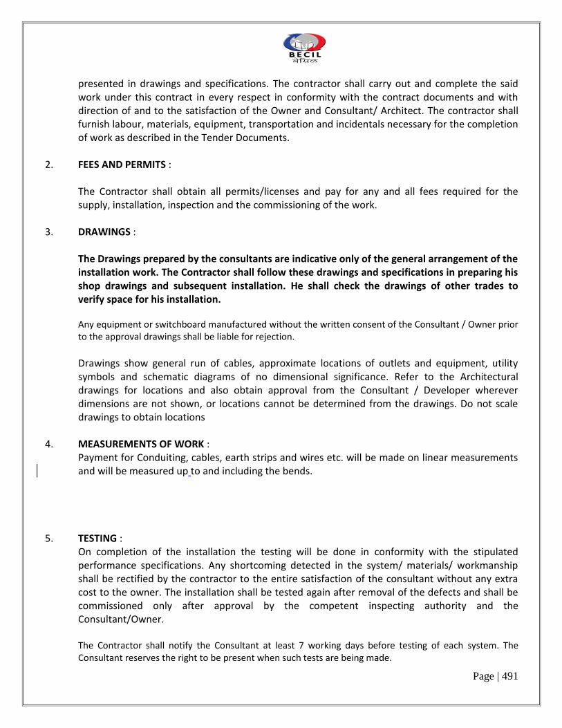
Page | 491
presented in drawings and specifications. The contractor shall carry out and complete the said work under this contract in every respect in conformity with the contract documents and with direction of and to the satisfaction of the Owner and Consultant/ Architect. The contractor shall furnish labour, materials, equipment, transportation and incidentals necessary for the completion of work as described in the Tender Documents.
2. FEES AND PERMITS :
The Contractor shall obtain all permits/licenses and pay for any and all fees required for the supply, installation, inspection and the commissioning of the work.
3. DRAWINGS :
The Drawings prepared by the consultants are indicative only of the general arrangement of the installation work. The Contractor shall follow these drawings and specifications in preparing his shop drawings and subsequent installation. He shall check the drawings of other trades to verify space for his installation.
Any equipment or switchboard manufactured without the written consent of the Consultant / Owner prior to the approval drawings shall be liable for rejection.
Drawings show general run of cables, approximate locations of outlets and equipment, utility symbols and schematic diagrams of no dimensional significance. Refer to the Architectural drawings for locations and also obtain approval from the Consultant / Developer wherever dimensions are not shown, or locations cannot be determined from the drawings. Do not scale drawings to obtain locations
4. MEASUREMENTS OF WORK :
Payment for Conduiting, cables, earth strips and wires etc. will be made on linear measurements and will be measured up to and including the bends.
5. TESTING :
On completion of the installation the testing will be done in conformity with the stipulated performance specifications. Any shortcoming detected in the system/ materials/ workmanship shall be rectified by the contractor to the entire satisfaction of the consultant without any extra cost to the owner. The installation shall be tested again after removal of the defects and shall be commissioned only after approval by the competent inspecting authority and the Consultant/Owner.
The Contractor shall notify the Consultant at least 7 working days before testing of each system. The Consultant reserves the right to be present when such tests are being made.

Page | 492
6. COMPLETION CERTIFICATE:
On completion of the installation a certificate in an approved form shall be furnished by the contractor. The contractor shall be responsible for getting the entire installation duly approved by other concerned authorities, as per government regulations, and shall bear all expenses in connection with the same.
7. SCOPE OF WORK
The scope of work to be carried out under this contract briefly comprises of: c) All Fire Alarm System. b) All PA system c) Access Control System d) CCTV e) Rodent System f) WLD
8. OWNER SUPPLY MATERIALS
The Owner shall be procuring some equipment and materials for incorporating in this project as listed in the Appendix – II. The contractor shall take the delivery of these materials/equipment from owners store and install them at site and commissioning the same in good condition.
The contractor shall keep the inventory of the materials received and used at site. The surplus or unused materials/equipment shall be returned to Owner’s store in good condition. If the contractor fails to give the accounting of materials/equipment, panel recovery at the rate mentioned in Appendix – II will be done from the contractors bill after allowing wastage allowance.
SECURITY SYSTEM TECHNICAL SPECIFICATION 1. INTELLIGENT ADDRESSABLE FIRE ALARM SYSTEM

Page | 493
The addressable and intelligent system shall be such that photoelectric /multi criterion sensors, manual call points, etc., can be identified with point address. The system shall be capable of:
Setting smoke sensor sensitivity remotely (from the Fire Work Station) to either high sensitivity
manually or on a pre-programmed sequence e.g. occupied/unoccupied period. The FAS shall be
able to recognize normal and alarm conditions, below normal sensor values that reveal trouble
condition, and above normal values that indicate either a pre alarm condition or the need of
maintenance.
Read-out or address an actual space temperature at thermal detector points. The operator shall
also be able to adjust alarm and pre alarm thresholds and other parameters for the smoke
sensors.
Provide a maintenance/pre-alert alarm capability at smoke sensors to prevent the detectors from
indicating a false alarm due to dust, dirt etc.
Provide alarm verification of individual smoke sensors.
Provide local numeric point address and LED display of device and current condition of the point.
Provide outputs that are addressable.
The distributed Intelligent Fire Alarm Control Panel (FACP) shall function as fully stand-alone panel as well as providing a communication interface to the central station. FACP shall have its own microprocessor, software and memory and should be listed under UL864 . The memory data for panel configuration and operation shall reside in non-volatile memory (EEPROM). It shall be possible to command test, reset and alarm silence from both the FACP and the central console. FACP switches shall allow authorized personnel to accomplish the following, independent of the central console :
Initiate a general alarm condition.
Silence the local audible alarm.
It shall be possible to acknowledge (Silence the local FACP audible without silencing the alarm
indicating devices (hooters).
Reset all zones (Logical Point Group) / points, after all initiating devices have returned to normal.
Perform a complete operational test of the microprocessor and memory with a visual indication
with each board.

Page | 494
Test all panel LEDs for proper operation without causing a change in the condition of any zone
(Logical Point Group)
Walk Test
FACP shall be backed up with its built in UPS power and shall also be connected to central DG Power available in the building. Software zones/loops shall be circuited and protected by Fault Isolation Modules such that in the event of a zone/loop short-circuit, not more than twenty (20) devices shall be left non-functional. Monitor modules shall be provided to monitor and address contact-type input devices. The monitor module shall be supervised by FACP. The FACP shall have Drift Compensation facility to compensate for environment. FACP shall be provided with following features :
Charger Rate Control
Control-by-Time
Non-Alarm Module Reporting
Day/Night Sensitivity
Periodic Detector Test
Device Blink Control
Remote Page
Drift Compensation
Trouble Reminder
NFPA 72 Sensitivity Test
Verification Counters
System Status Reports
Walk Test
Security Monitor Points
Maintenance Alert
Alarm Verification
System Configuration Report

Page | 495
Printer Interface
System Point Report
Event Historical log
Programmable Automatic Timed and Manual Signal Silence
Programmable Manual Signal Silence Inhibit Timer
Control-By-Event with Boolean Logic and Timer Control
The FACP should truly field programmable. The FACP should have a degraded mode of operation. Power supply unit of FACP shall have following characters:
The main power supply shall be 230 VAC±10%, 50 Hz±1% and shall in turn provide all necessary
power of the FACP.
It shall provide a battery charger for 24 hours for standby power using dual-rate charging
technique for fast battery recharge.
It shall provide a very low frequency sweep earth fault detect circuit, capable of detecting earth
faults on sensitive addressable modules.
It shall be power-limiting using Positive Temperature Coefficient (PTC) resistor.
It shall provide indication for battery voltage and charging current.
DETECTORS & ADDRESSABLE DEVICES General features common to all detectors:
Compatibility: All automatic fire detectors shall be interchangeable without requiring different
mounting bases or alterations in the signal panel.
Sensitivity: On average 30 mgs of burned material per cu.m. (As measured in a 1 cu.m. chamber)
shall release an alarm sensitivity which shall be adjustable according to the use of the space.
Power Consumption: Each detector shall use the minimum of power, for economic circuits, so
that it shall have capacity to connect at least 99 detectors, 50 modules and 20 fault isolator
modules in one loop.
Built-in-response indicator: Each detector shall incorporate indicator “LED” at the detector which
shall blink during normal condition and light up on actuation of the detector to locate the
detector which is operated. The detector shall not be affected by the failure of the response
indicator lamp.

Page | 496
Maintenance: All detectors shall be fitted either with plug-in system or bayonet type connections
only, from the maintenance and compatibility point of view.
Construction: The detector shall be vibration and shock proof. When disassembling for cleaning
purposes, its components must not be damaged by static over voltage.
Atmospheric and Thermal Disturbance: The detector shall so designed as to be practically immune
to environmental criteria such as air currents, humidity, temperature fluctuations, and pressure
and shall not trigger false alarm, due to the above conditions.
Continuous Operation: An alarm release shall not effect a detector’s functioning. After resetting
the alarm, the detector shall resume operation without any readjustment.
Adaptability to ambient conditions: Detectors shall be designed for adaptability to humid
locations. No performance deterioration shall be acceptable.
The monitor module shall provide address-setting and shall also store an internal identifying code which the Fire Alarm Control Panel shall use to identify the type of device. The control module shall provide address-setting and shall also store an internal identifying code which the control panel shall use to identify the type of device. All field hooters should preferably be addressable and software configurable. All hooters should be able to provide at least a minimum of 3 different tones, which should be user configurable. The minimum decibel level of each hooter should be 90db. All hooters should be UL/FM listed. All hooters shall have coupled strobe lights of 110Cd intensity. EMERGENCY VOICE EVACUATION (EVAC) & TALK BACKFIREMAN PHONE SYSTEM
The FACP shall contain all equipment required for all audio control, telephone system control, signaling and supervisory functions. This includes speaker zone indication, telephone circuit indication and control, digital voice units, microphone and main telephone handset. Function: The EVAC system equipment shall perform following functions:
Operate as a supervised dual channel emergency voice communication system.
Operate as a two-way emergency telephone system control center.
Audibly and visually annunciate the active or trouble condition of every speaker circuit and
telephone circuit.
Audibly and visually annunciate any trouble condition of tone generators and digital voice units
required for normal operation of the system.
Provide automatic, digitally-recorded voice messages and tones which may be field-programmed
through the microphone.

Page | 497
FIRE ALARM GRAPHICS SOFTWARE (FAS)
The status of each detector shall be monitored by the FAS.
Using the FAS, the operator shall be able to adjust the sensitivity of any detector.
Using the FAS, the operator shall be able to define the entire database for the file system. Fire
system which are not field programmable shall not be accepted.
The FAS operator shall be able to acknowledge alarms or trouble messages at the FAS.
It shall be necessary for all alarm or trouble conditions to be acknowledge at the fire system
central panel.
FAS software shall be upload/download type as well as with graphic facilities.
All devices & detectors shall be visible on building plans superimposed in FAS software.
2 PUBLIC ADDRESS SYSTEM
The objective of the PA system is primarily to inform and help to evacuate people in an orderly manner in an event of any emergency by manual announcement. It can also be used for playing music.
The Public Address System shall serve to
Play the music Make general announcement Transmit fire tone under fire condition
Different levels of priorities as per following shall be allotted to different signals for transmission through the same speaker.
Emergency announcements - highest priority Fire tone/Paging - Next Music - Least The chronology of fire announcements floor wise (one floor up/down) will be defined
by Client.
For the purpose of PA system the zones are Work station & All the other rooms and shall have general announcement and paging services.
All control consoles shall be placed in the BMS room.
A separate zoning to be provided for the Meeting room and all the cabins speakers.
Announcement and background music shall be played from the BMS room

Page | 498
The emergency announcement shall have highest priority, it will integrated with the fire alarm system. The speakers shall be distributed in the entire floor and configured in different zones.
The announcement shall be made in Individual mode i.e. one zone at a time or to all zones simultaneously in ALL CALL mode.
Volume controller not to be provided to all the closed cabins and meeting rooms.
After the confirmation of fire, the client safety, security team makes that there is fire and start the evacuation process
If is a false alarm, an announcement is made NOT to evacuate Public Address system comprising of
a) Metal Cabinet. b) Ceiling mounted speakers. c) Public Addressing Amplifiers d) Central Control Console.
The P.A System Controller will have a Goose Neck microphone, Multi channel evacuation P.A Console with a Tone generator& a speech processor.
The P.A system will also be capable of taking an external voice input from the builder P.A system for them to use address the occupant’s in client area during any emergency.
3. ACCESS CONTROL SYSTEM
I. Software 1. System Overview 1.1. The Integrated Security Management System (ISMS) shall be a modular, networked access control
system capable of handling large proprietary corporations with multiple remote sites, alarm monitoring, video imaging, badging, paging, guard tour. The system shall allow for easy expansion or modification of inputs, outputs, and remote control stations.
1.2. The system control at the central computer location shall be under a single software program
control, shall provide full integration of all components, and shall be alterable at any time, depending upon the facility requirements. Reconfiguration shall be accomplished online through system programming, without hardware changes.
1.3. The software program shall be a true 32-bit, 3-tier client/server, ODBC compliant application
based on Microsoft tools and standards. The software program shall operate in one of the

Page | 499
following environments; Windows 2003 Server, Windows Vista Business, Windows XP Professional SP2, Windows 2000 Professional or Server using Service Pack 4.
1.4. The system shall support multiple communication servers on a LAN/WAN, to provide distributed
networking capabilities, which significantly improve system performance. 1.5. The database architecture shall be MSDE 2000 as standard with the capability to utilize Microsoft
SQL Server 2005; SQL Server 2005 Express Edition or SQL Server 2000. 1.6. The system shall have the capability to communicate with the control panels via LAN/WAN
connections utilizing industry standard communication protocol. 1.7. The software program shall use Abstract Devices (ADV) for representing hardware devices in the
system. The ADVs shall be used in Floor Plans to provide the user interface to control and monitor the system, and shall also be used in the Data Trees to organize, display, and control system information.
1.8. The system shall support both manual and automatic responses to alarms entering the system.
Each alarm shall be capable of initiating a number of different actions, such as activation of remote devices, door control, and activation of WAV files.
1.9. The system shall provide both supervised and non-supervised alarm point monitoring. Upon
recognition of an alarm, the system shall be capable of arming or disarming alarm points both manually and automatically, by time of day, and by day of week.
1.10. Access control functions shall include validation based on time of day, day of week, holiday
scheduling, site code and card number verification, automatic or manual retrieval of cardholder photographs, and access validation based on positive verification of card, card and PIN, card or pin, pin only and Site Code only.
1.11. Alarm events with defined priorities shall be able to pop-up automatically in an Alarm event
window for operator attention. The pop-up shall display the name of the event (reader, alarm point, cardholder or system alarm), time, date, site, account, if a card event the card number, type of event and cardholder name. An event counter shall also display the number of times the event was reported to the Alarm event monitor prior to Acknowledgement or Clearing the event. Event instructions shall be made available by double clicking on the event.
1.12. The Alarm event window shall allow the operator to initiate a physical response to the event as well as a written response. Responses shall include but not be limited to: acknowledge, clear, open a pre-programmed floor plan, energize, de-energize, pulse, time pulse, add comment, shunt or un-shunt.
1.13. Assigned passwords shall be possible to define the levels of system operation for each individual
operator. System operation for individual operators shall include, but not be limited to, restricted

Page | 500
time periods for login, available accounts and default language selection at login. Operator actions range from no view or control rights to basic monitoring including the ability to block the viewing of card and or personal identification numbers, to full control of the system including programming.
1.14. The system programming shall be user friendly, and capable of being accomplished by personnel
with no prior computer experience. A quick start wizard shall allow the operator to easily program a system including basic time zones, access panels (IP connection, Modem Pools or direct connections to an RS-232 port), card activation to a general purpose access area and deactivation date. The software shall utilize drop boxes for all previously entered system-required data. The programming shall be MENU driven and include online “Help” or “Tutorial” information, as well as online data entry examples. The Help shall be available by using the F1 key. When using the F1 help access, the help menu will provide detailed information relative to the operation that the user is performing without the need to key in additional search parameters. An operation Tutorial shall also be provided with the access control software. The contents of the Tutorial shall include, but not be limited to: Floor plan setup and control, Visitor management integration, and Intrusion integration and operation.
1.15. After installation, the Customer shall be able to perform hardware configuration changes. These
hardware configuration changes shall include, but not be limited to, door open time, door contact shunt time, point and reader names, when and where a cardholder is valid, and the ability to add or modify card databases as desired; For the intrusion system, any function that can be programmed from a physical keypad shall also be available from the system’s virtual keypad, without the services of the Contractor or Manufacturer.
1.16. Equipment repair shall be able to be accomplished on site, by module replacement, utilizing spare
components. Basic System Capabilities
The following functional capabilities are considered essential for the system described in this specification. The
capabilities are to be considered standard, without the need for add-on software or hardware.
o General
i. All databases will have the ability to ADD, DELETE, REPORT, VIEW or EDIT information. ii. Provide storage of all system transactions in a retrievable file.
iii. Log all events by time and date with reference to GMT. iv. Provide capability to store all or selected system transactions to a disk file. v. Provide ability for CUSTOMER to make system configuration changes such as, but not limited to
door open time, door contact shunt time, point and reader names, when and where a cardholder is valid, and the ability to add or modify card databases at any time.

Page | 501
vi. Support “Global Anti-passback”, allowing cardholder to enter/exit any card reader on the same RS485 drop line.
vii. Duress feature where when a PIN is used in conjunction with a card read, the number of digits are selected at the keypad where the PIN number is a value of one different from the normal PIN.
viii. Provide mode of system operation that stores system commands that were not accepted by the hardware.
ix. Provide mode of system operation that requires the operator to enter a response to an event when acknowledging it from the alarm view window.
x. Provide mode of system operation that allows acknowledged alarms to be automatically cleared. xi. Provide mode of system operation where un-acknowledged events will cause the computer to
continuously emit a pulsating beep until all un-acknowledged alarms are acknowledged. A momentary silence feature shall allow the beeping to cease for up to 60 seconds. The silence feature shall also provide a visual count down to when the beeping will begin again.
xii. Provide mode of system operation where when an acknowledged, but not cleared event will be reissued requiring acknowledgement when the event changes to an alarm or trouble state.
xiii. Provide mode of system operation that does not allow the operator to clear an alarm prior to it being restored to normal.
xiv. Provide ability for manual operator control of system output relays. The manual functions shall include the ability to energise, de-energise, return to time zone, or pulse the output relay. The pulse time shall be a programmable setting.
xv. Provide ability for manual operator control of system doors. The manual functions shall include the ability to Lock, Un-Lock, Shunt, Un-Shunt and Return to Time Zone.
xvi. Provide ability to automatically display stored “video image” of cardholder xvii. The cardholder “video image” pop-up shall be activated based on a priority level set to the
cardholder or reader. Information in the pop-up shall include, but not be limited to the cardholder’s primary image a live video pop-up showing the person who initiated the pop-up, entrance name, time, date, cardholder name, and status. User shall be able to display up to 40 note fields. The size of the pop-up(s) shall be adjustable by the operator.
xviii. Support multiple card reader technology including Proximity, Wiegand effect, Biometrics, Magnetic stripe, Bar Code, Keypad, Card/keypad (PIN), High-speed long range Vehicle ID, Smart Card
xix. Provide a means for scheduled automatic backups of any or all database system files. A means to restore these files from a simple menu shall exist.
xx. Provide the ability to address up to 2 serial communication ports, where each port can be configured for either hardwired or dial-up. When configured for dial-up, any one port can support multiple dial-up locations.
xxi. Communication from the access control server to the remote control panels shall be selectable. Communication options shall be via RS-485 converter, dial-up, leased line from a defined communication port or by LAN/WAN using an IP address for direct connection to the remote RS-485 converter via network interface card. When using IP addressing it shall be un-acceptable to use a communication port converter device on the communication server side of the transmission. A minimum of 64 such IP connections shall be allowed.
xxii. All commands and updates to the panels shall be verified and shall automatically retry if communications have failed.

Page | 502
xxiii. Provide the ability to select ACK/NAK communication feature by communications port for either dial-up or hardwire.
xxiv. Provide a system scheduler that shall automatically: 1. Call remote locations to retrieve history transactions and update panel information,
including time and date. 2. Activate or deactivate cards locally or at remote dial-up sites. 3. Initiate a pre-programmed command event/action. 4. Synchronize system to controller time.
xxv. Provide the ability to initiate an alarm based on a transaction state. A transaction state shall be
defined as but not limited to Normal, Alarm, Trouble, Ajar, Trace, Not Found, Anti-Passback Violation, PIN Violation, Time Zone Violation, Site Code Violation and System Alarms including Panel Com, Panel Power Failure, Modem Pool, Guard Tour, and Tamper.
xxvi. A host grant mode of operation shall exist that requires the host computer to grant accesses to “valid” cards. An alternate host grant mode shall allow the card access information to be downloaded along with unlocking the door for “valid” cards.
o Card Database
i. Provide a simple card and card holder database import utility. The utility shall be password protected and accessible only to administrators of the access control system. Information that can be imported shall include but not be limited to: First Name, Last Name, card number, activation date, de-activation date, status, up to 40 note fields and photo images. A simple CSV (comma separated value) file shall be used for the importing of data and image file names.
ii. Cardholder information shall include unique card number up to 15 digits and optional Personal Identification Number.
iii. Allow multiple cards per cardholder. iv. Allow for up to 32 access levels to be assigned to a card, or a single “precision” access level.
When using “precision” access levels it shall be possible to create a unique access level per card using an existing access level as a baseline template. This customized card access level shall have both beginning and ending dates.
v. Provide 40 user definable fields. vi. Each card holder note filed shall allow the option to be entered as free form data or
structured data. Structured data shall be by use of a template or drop list. The template and drop list shall be created by the operator. The capacity of the template shall allow for up to 65,000 characters.
vii. Provide special card options that include, but are not limited to: 1. Time zone reference, which defines valid time. 2. Visitor use, which provides a specified activation date and expiration date (spanning years). 3. Trigger control value, which can initiate a predefined procedure at the intelligent control
independent from any control function from the system computer. viii. Provide a card “Trace” function. The Trace function shall allow normal access control, but will
provide a tracking alarm at the system monitor.

Page | 503
ix. Provide ability to store digital images and written signature of cardholder. x. Provide the ability to prioritise specific card usage from 1 to 99 with separate priority options
for Anti-passback, Trace, PIN Violation, Normal, Not Found, Expired, Host Grant, Site Code and Time Zone card activities or violations.
xi. Allow the user the ability to assign an operator message per card event state. xii. Upon editing card information, the updated information shall be sent automatically to the
appropriate access control panel, when hardwired, with no other user intervention. If the port is dial-up, the entry will be stored on disk and shall be updated when connection is made to the remote loop. If the scheduler is used, then card updates shall be sent based on scheduling.
xiii. In a traditional (Wiegand) 5-digit card database, the numbers 0 and 65,535 shall not be valid card numbers as some devices transmit these numbers on an improper read.
xiv. In a 15-digit card database, the number 0 shall not be a valid card number as some devices transmit this number on an improper read.
xv. A card shall have the ability to be allowed to access one or selected accounts up to all available accounts.
o Access Levels
i. It shall provide the ability to define specific times of access, specific readers for access, provide a template of a defined access level detail, where changes can be made to the template and saved as a new access level detail and provide an access control tree structure that allows groupings of entrances. User shall have the ability to group program all entrances on the branch or make specific changes to individual entrances.
o Alarm Monitoring – Alarms Only View
i. Report alarm point activity. ii. Provide colour for each specific alarm point action of “Alarm”, “Normal” and “Trouble”,
conditions. iii. Provide the ability to access the default floor plan graphic for any active alarm point by a right
click option, to acknowledge any alarm, card, or reader activity based on priority and to bypass alarms in the system
iv. Execute alarm notification in all modes of operation. v. Provide display of system activity with the higher priorities displayed at the top of the list with
identical points stacked with a frequency count of each point’s change of state. vi. Provide ability for the operator to acknowledge and clear alarms from display. Prior to
acknowledgment, the user shall be allowed to enter a response per alarm. The system shall offer a means to require acknowledgement of an alarm before it can be cleared.
vii. Provide a display of the most current transactions in real time. viii. Provide the ability for dynamic alarm monitoring of alarm points in real time on the system
computer’s video display terminal. ix. Provide an alarm view filter that is structured as a tree allowing the operator to select
individual devices or groups of devices to be viewed. x. Provide a “Panel Not Responding” alarm if communication to a panel is lost.

Page | 504
xi. Provide real time printing of alarms as they occur by line printing with a dot matrix printer or provide printing of alarms, one page at a time, using typical Windows page printing.
o Alarm Monitoring/System Control – Tree View
i. Provide the ability for dynamic alarm monitoring of alarm points in real time on the system computer’s video display terminal
ii. Provide colour and icon shapes for each specific alarm point action of “Alarm”, “Normal” and “Trouble”, and “Shunted”.
iii. Access control panels in the alarm tree, like alarm points, shall also indicate if they are in the buffered mode of operation as well as any “system” related alarm such as “Tamper” or “Primary Power Loss” or Loss of communication.
iv. Devices connected to the communication server shall provide additional popup information as to the communication port or IP connection the device is programmed for.
v. Provide a means to launch a Virtual keypad from an intrusion panel partition to monitor the physical keypad remotely and to administer programming changes via the Virtual keypad.
o Operator Database
i. The software shall allow the assignment of operator levels to define the system components that each operator has access to view, operate, change or delete.
ii. The ability to view, edit or delete cardholder sensitive information such as note fields, card number and PIN shall be definable by field per operator.
iii. Define the accounts that the operator has access to.
iv. Provide the ability to log operator actions in the history files. v. Provide default language to be used based on operator’s login.
vi. Provide specified time periods that the operator can log in.
o Reports
i. Provide reporting capability for printing of selected system transactions from the disk files by specific time and date selection, range from time and date to time and date, or from start time to end time each day of the selected date range.
ii. Provide feature to generate a history report for an alarm point(s) state. An alarm point state shall be defined as Normal, Alarm, Trouble, or Ajar.
iii. Provide feature to generate a history report of system alarms. A system alarm state shall be defined by panel and include any of the following information: communication, ground fault, power, panel reset, low voltage, panel tamper, and loop communication.
iv. Provide feature to generate a history report for a card(s) state. A card state shall be defined as Normal, Trace, Not Found, Anti-Passback Violation, PIN Violation, Time Zone Violation, Site Code Violation, or Expired card. Additional search criteria shall include cardholders that meet up to at least 3-note field restriction and filter the report with defined reader location(s).
v. Provide feature to generate a history report for system operator(s) activities. The report shall include time, date, operator name the device associated with the action and the type of

Page | 505
action performed by the operator. Activities shall include but not limited to: acknowledged and cleared transactions, door and relay control such as unlock, lock; door and input control such as shunt, unshunt; login, logout, panel initialisation, panel buffer and panel unbuffer.
vi. Provide complete database reporting of all data programmed into the system data files. vii. Provide a means to define how long a card holder has been in a defined area. This report shall
allow the time to be accumulated representing an attendance report. The definable filters shall include time/date range, reader(s) definition, card number, card holder and note field. The output of the report shall allow sort options to include First Name, Last Name, Event Time, and Card Number. The sorted data shall be selectable as Alpha or Numeric sorting and Ascending or Descending.
viii. Provide feature to generate a report based on the frequency of usage of a card. The report shall allow the operator to define a time/date period, a minimum and maximum usage limit, a means to define which reader or readers should be used to filter the report and the ability to further define the type of card to be reported on based on note field selections. This report shall also provide a disposition function. The cards meeting the filtering criteria shall be acted upon based on the disposition setting. Disposition settings shall include but not be limited to: Report only, De-activate the card or Re-assign to a specified an access level. This report shall be available in the event scheduler. When defining when to run the report an option to select the number of previous days to run the report against shall be provided. As an example a scheduled weekly report for the last 14 days could generate allowing for an overlap of time if desired.
ix. Provide a means to create report templates. Report templates shall include, but not be limited to, History and Card Holder information. The templates shall be able to be assigned to a scheduler to run automatically per the scheduler settings.
o Tracking/Muster Report
i. A tracking feature shall allow the system operator to identify an area and the person(s) in that area, which shall be defined by readers representing an IN or OUT read status.
ii. Defined areas shall provide an automatic update of how many cardholders are in the area. iii. A view displaying all card holders in a defined tracking or muster area shall have the ability to
be sorted in columns where by clicking on the column the data in the column shall be sorted. At a minimum, the columns can be sorted by: Card Number, Status, Card Holder, Reader, and Time/Date.
iv. A Muster area shall be defined by a reader(s) used to “muster” individuals in the event of an emergency.
v. Reports shall be generated for all muster or tracking areas in the system. vi. Tracking areas shall include “nested” areas. Nesting allows for various reports from a large
area to smaller areas within the large area. vii. A Tracking and Muster area screen shall be continually updated with the most recent card
activity, therefore minimizing the time required generating a report. viii. A history-priming feature shall load history activities for the defined amount of hours when
the software is started. This priming feature shall be implemented in the event that the system computer is offline when a muster call is initiated, thereby allowing the

Page | 506
implementation of the tracking and muster features of the software. The history priming time shall be operator selectable in 1-hour increments up to 99 hours.
o Time Zones
i. Time zone definitions shall include Starting time, Ending time, Days of the week, and Holiday override.
ii. Minimum time zones that can be assigned to a panel shall be 63 and maximum unlimited. iii. Holidays shall be definable in two different time zones allowing different time schedule to be
programmed for each holiday type. o Floor Plan Graphic
i. Provide the ability to import floor plan graphics stored in a WMF format and to associate all
hardware devices (access, intrusion) to floor plan graphics allowing the user to control and monitor the system.
ii. Provide the ability to link floor plan graphics together in a hierarchy fashion and allow multiple floor plan views to be displayed simultaneously.
o Front End Software Specifications
i. Databases: The software shall provide edit, add, delete, search, sort, and print options for records in selected databases.
ii. Printer Output: The software shall direct user-selected activity to the Windows supported
printer.
iii. Monitor Display: The software shall display all system activity on a colour monitor in real time, except for remote locations configured as dial-up. The software shall allow a WAV file to be played upon all alarm conditions. The software shall provide an acknowledge function for all incoming alarm messages that are defined for alarm acknowledgment.
iv. Disk Storage: The software shall store user-selected activity on the hard disk. Report options
shall recall selected history information from the hard disk. The user may request report information based on selected cardholders, specific areas and/or specific times. The software shall allow archiving by defined dates.
English Descriptions: The software shall support descriptive names for all database entries. The card database shall include name, number, PIN, access level, status, activation, and expiration date or limited usage and 40 user-defined fields.
II. ACCESS CONTROL FIELD HARDWARE DEVICES

Page | 507
The security management system shall be equipped with access control field hardware required to receive alarms and administer all access granted/denied decisions. All field hardware shall meet FCC CE C-Tick requirements. The system shall include the 2-reader intelligent controller. The IP-enabled controller is an advanced access control panel capable of providing solutions for medium to large applications. The controller provides power and flexibility with its 32-bit CPU architecture, TCP/IP protocol support, flash memory for firmware and large local card holder database. The controller is designed to operate off-line, making access control decisions independently from a PC or other controlling device. It can also be connected to a host computer for system configuration, alarm monitoring and direct control. Connectivity to the host computer is accomplished via TCP/IP network connection. The board combines intelligent controller and reader interface into one complete unit. It connects for two readers via Wiegand controlling two doors. The controller can support up to 62 doors via RS485 multi-drop communication where 30 downstream controllers are connected to the gateway controller. This architecture can reduce the usage on LANs by using only one TCP/IP address to 62 doors. It accommodates a card database of 55,000 cards, and a transaction buffer of 45,000 transactions. It is designed with tile mounting configuration. Specifications Database: • Cardholder capacity: 55,000 • Transaction storage: 45,000 • Flash programming for firmware revision updates • Access level: 128 • Holidays: 255 • Time zone: 127 • Card reader formats: 128 Wiegand format support • Credential facility codes: 8 • Dedicated tamper alarm • Dedicated power fail alarm • Real time clock:
- Geographic time zone support - Leap year support
• Embedded web server to configure network attributes Environment: • Temperature: 0 to 50° C operational
-55 to 85° C storage • Humidity: 0 to 85% RHNC

Page | 508
Communication: • Ethernet port connected to TCP/IP network as master panel • RS485 multi-drop connection for downstream panels Onboard I/O: • 2 Readers, expandable to 62 readers per gateway controller • 8 Supervised inputs • 4 Relay outputs Operational Functionality: • Operational modes:
- Card only - Card and PIN
• Maximum site codes: 8 digit • Anti-Passback support:
- Local - Global - Forgiveness
• Interlocks: 256 Approvals: • CE/FCC/C-TICK
Standard Read Range Smart Card Reader:
Reader shall be read only reader
Provide surface mounting style 13.56 MHz contactless smart card readers suitable for minimal space mounting configurations as shown on the project plans.
Contactless smart card readers shall comply with ISO 15693, ISO 14443A (CSN), and ISO 14443B and shall read credentials that comply with these standards.
Data security with cards shall use 64-bit authentication keys to reduce the risk of compromised data or duplicate cards. The contactless smart card reader and cards shall require matching keys in order to function together. All RF data transmission between the card and the reader shall be encrypted, using a secure algorithm. Card readers shall be provided with keys that are compatible with the cards.
The contactless smart card reader shall provide the ability to change operational features in the field through the use of a factory-programmed command card. Additionally, firmware may be updated by flashing the reader. Command card operational programming options shall include:
o Output configurations
o LED & Audio configurations

Page | 509
o Keypad configurations
Contactless smart card readers shall provide the following programmable audio/visual indication:
o An audio transducer shall provide various tone sequences to signify: access granted, access denied, power up, and diagnostics.
o A high-intensity light bar shall provide clear visual status (red/green/amber) that is visible even in bright sunlight.
Contactless smart card readers shall meet the following physical specifications:
o Dimensions: 1.90” x 4.04” x .80” (4.83cm x 10.26 cm x 2.03 cm)
o Weight: 3.2.oz (90.7 g)
o Material: UL94 Polycarbonate
o Three-part design with separate mounting plate, reader body, and cover.
o Color: Black.
Contactless smart card readers shall meet the following electrical specifications:
o Operating voltage: 10 – 16 VDC, reverse voltage protected. Linear power supply recommended.
o Current requirements: (average/peak) 61/178mA @ 12 VDC
Contactless smart card readers shall meet the following certifications:
o UL 294
o Canada/UL 294
o FCC Certification
o Canada Radio Certification
o EU and CB Scheme Electrical Safety
o EU – R&TTE Directive
o CE Mark (Europe)
o IP55 Rated
o C-Tick (New Zealand/Australia/Taiwan)
Contactless smart card readers shall meet the following environmental specifications:
o Operating temperature: -30 to 150 degrees F (-35 to 65 degrees C)
o Operating humidity: 5% to 95% relative humidity non-condensing
o Weatherized design suitable to withstand harsh environments
Contactless smart card reader cabling requirements shall be:
o Cable distance: (Wiegand): 500 feet (150m)
o Cable type: 5-conductor #22 AWG with overall shield
o Standard reader termination: 18” (.5m) cable pigtail
Warranty of contactless smart card readers shall be lifetime against defects in materials and workmanship.
Electromagnetic Lock:
Single Leaf doors.
Surface Mount Electromagnetic Lock with built in magnetic read switch contractor shall consider the U , L , Z brackets based on the site conditions accordingly

Page | 510
The EM Lock shall have minimum with following specifications
a. Suitable for surface mount on single leaf doors
b. Current Draw: 500mA / 12V, 250mA / 24V
c. Dual Voltage: 12V / 24 V
d. Holding Force: About 600 lbs
e. Built-in magnetic read switch and Voltage Spike Suppressor
f. UL Listed
Double Leaf doors.
Surface Mount Electromagnetic Lock with built in magnetic read switch contractor shall consider the U , L , Z brackets based on the site conditions accordingly
The EM Lock shall have minimum with following specifications
a. Suitable for surface mount on double leaf doors
b. Current Draw: 1A / 12V, 500 mA / 24V
c. Dual Voltage: 12V / 24 V
d. Holding Force: About 600 lbs
e. Built-in magnetic read switch and Voltage Spike Suppressor
f. UL Listed
Cable: Following shall be the cables for the various components of the networked access control system Reader - six conductor shielded, 18 AWG Power - twisted pair, 18AWG RS-485 - 24 AWG, 4,000 ft. (1,200 m) max., 2 twisted pairs' with shield (120W, 23pF) RS-232 – 8 conductors 24 AWG, 25 ft. (7.6 m) max. Alarm input – 2 conductor twisted pair, 30 ohms max.
4. CCTV SYSTEM SPECIFICATION
Fixed Dome Camera
The High Resolution DSP Color Mini Dome Camera shall include, as a minimum, the following features/functions/specifications:

Page | 511
1. The High Resolution DSP Color Mini Dome Camera shall incorporate a 1/3-inch Charge-coupled device (CCD), and a minimum of 530 TV lines of resolution utilizing an effective pixel count of no less than 768 (H) x 494 (V) NTSC, 752 (H) x 582 (V) PAL.
2. The High Resolution DSP Color Mini Dome Camera shall provide excellent color performance in
extremely low light, down to 0.1 lux @ F1.2 (30IRE). 3. The High Resolution DSP Color Mini Dome Camera shall have an internal amplifier that applies
gain to the signal from the CCD. The amplifier must operate when there is insufficient light in the scene to produce an acceptable video output level, and must only apply as much gain as is necessary. The camera shall incorporate one level of automatic gain compensation (AGC), allowing the user to achieve the optimal balance of noise and low light performance in demanding environments.
4. The High Resolution DSP Color Mini Dome Camera shall support the use of Auto Iris/Direct Drive
lens connected to the camera via 4-pin molex socket located from the inside of the camera housing. The camera must provide DC power drive signal to the lens. The camera must provide power to the lens. Iris level controls are Tact Switches accessible from the front of the camera.
5. The High Resolution DSP Color Mini Dome Camera shall support the use of Fixed lens, focal length
is 3.6mm, each. 6. The power consumption of the High Resolution DSP Color Mini Dome Camera shall be no more
than 1 watt. (12VDC power supply) 7. The High Resolution DSP Color Mini Dome Camera shall have a signal to noise ratio of 48 dB with
the AGC off. 8. The High Resolution DSP color Mini Dome Camera shall incorporate auto-tracking white balance
to constantly monitor the light and adjust its color. It has a color temperature range of 2,500K to 8,000 K.
9. To allow the image to be viewed properly on a standard monitor, the High Resolution DSP Color
Mini Dome Camera’s default gamma value must be 0.45.
Color Monitor
Features: • 21" flat square picture tube • 450 TVL • Convenient front panel push-button controls

Page | 512
• On-screen display/setup menus (OSD) • Heavy-duty metal cabinet • NTSC/PAL (auto-sensing) • Video loop-through with automatic termination • Supports two composite and one S-VHS video input (looping) • Universal power supply • Audio Input/Output- 2 channels • Switchable overscan and underscan • Available in black and cool grey cabinet colors Specifications. Picture Tube: 21" (53 cm) flat square tube) Resolution: Horizontal: 450 TV lines Video Standard: NTSC/PAL (automatically detects) Phosphor: P22 Dot Pitch: In-line 0.71 mm stripe Defection: 90° angle Electrical Power Source: 90 to 254 VAC 50 Hz or 60 Hz Power Consumption: 80 Watts Power Supply: NEMA 5-15P, UL AC Input Connector: IEC 320 Scanning Frequency Horizontal: 15.75 KHz (NTSC); 15.625 KHz (PAL)
Digital Video Recorder
Stand Alone Digital Video Recorder • 16 analog video input channels • 1 channel audio recording & playback • Recording, Playback, Back-up, Network recording, and Network playback at the same time (Pentaplex) • Total 480/400 ips (NTSC/PAL) recording speed for recording speed • Total 480/400 fps (NTSC/PAL) display

Page | 513
speed • Built-in splitter for split screen monitoring (1/4/ 9/13/16 split mode) • Max. 4TB storage capacity (Through IEEE 1394 port for external HDD) • Intelligent file system for managing event recording data DVR supports 16 analog video channels. Video, Audio, and Text Event-Logs are digitized and stored on two internal hard-drives. Using a ‘Proprietary Wavelet Algorithm,’ average file size is 1-5KB while still maintaining clarity high enough for facial-recognition. In addition, Wavelet-compressed images are impossible to manipulate. With our proprietary Wavelet Algorithm, DVRs process analog video into crisp, clear, and court-admissible pictures that are up to 500% smaller than comparable to JPEG images. It also allows users to record and playback audio for one channel. With ‘Quick Setup’, DVR can be setup and begin recording in 5 minutes. It starts to record as soon as power is supplied and CCTV cameras are connected. The default settings offer qualified and efficient way without the hassle of confusing menus. Equipped with two IEEE 1394 ports (Fire-Wire), can expand its recording capacity up to 4TB easily. Windows' FAT32 formatted HDD is compatible with DVR. The data can be simply backed up by connecting the HDD to the PC to review critical images. And with one USB port, user can copy small sized images. • ATM/POS transaction text information recording and search with corresponding video • 16 sensor inputs and 4 alarm outputs • Built-in hardware motion detection (64- division comparison) • Back-up with IEEE 1394(WiFi) • PTZ Control (Preset support) via RS 232 or RS 485/RS422 • User-friendly 32bit True-color Graphic OSD Menu • Dynamic IP (DHCP, Floating IP) support • Optimized Wavelet compression: 1-5KB (Average file size with standard image

Page | 514
quality) Features • Embedded Linux OS for excellent stability and reliability • IR remote controller (User can control PTZ with remote controller) 5. ULTRASONIC RODENT REPELLENT SYSTEM
Ultrasonic Rodent Repellers are high frequency signal generators. These signals are fed to the transducers which in turn convert them into high frequency sound waves (well above the 20 Khz frequency which is the upper limit of the hearing range of humans). The transducers emit intensive sound waves at high decibels (sound pressure) that are audible and painful to rodents but are inaudible and harmless to humans. The rodents usually leave the area being protected by the ultrasound waves immediately and at other times it may take as long as 4 to 6 weeks before there is significant reduction in rodent infestation. They do not get killed. The transducers are quiet. If you cannot hear them, do not think that the unit is not working. The powerful sound waves generated by the transducers of the repellers are within the hearing range of many pests, and cause them pain and discomfort. Sometimes, the pests will leave the area being protected immediately, and at other times it will take as long as four to six weeks before there is a significant reduction in infestation. The transducers are quiet. If you cannot hear them, do not think that the unit is not working. You cannot hear ultrasound. It takes three to six weeks for the system to have it's desired effect on the Rodents. The Ultrasound emitted by the machine becomes unbearable to the rodents and they try to run away. Rodents get irritated and look out for quiet safer areas. As a result of the continuous sound pressure emitted by the machines some rodents become violent hence there should be an opening like a door or a window to escape. Post commissioning of the system sometimes shows increased rodent activities, what we say as the regular Post Commissioning Syndrome. The agitated rodents unable to bear the sound waves are disoriented and vent out their discomfort until they are flushed out or find an escape route. Rodents stop entering the areas being protected by Ultrasonic Pest Repeller, because the ultrasonic sound waves hit their eardrums and cause them considerable pain and discomfort. They do not get immune since the sound output is at varying frequencies. They do not die unless they get trapped in a particular place for days together or are under consistent exposure to ultrasonic sound. Repeller will help to reduce these losses.
6 SPECIFICATIONS FOR CONDUIT MATERIALS:

Page | 515
M.S. conduits shall conform to Indian Standards IS : 1653 - 1964 -Specification for Rigid Steel
conduits for Electrical wiring with the latest amendments. M.S. CONDUITS:
M.S. conduits shall be solid drawn or lap welded conduits. Stove enameled inside and outside
with minimum wall thickness of 1.6 mm for conduits upto 20 mm diameter and 2.0 mm wall thickness for conduits 25 mm diameter and above.
PVC conduits to be used for concealed work for all systems except Fire Alarm & Computer system where M.S. conduits shall be used. PVC conduits shall conform to Indian Standards IS : 9537(Part-3)-1983 -Specification for conduits for Electrical Installation (Part-I) General Requirements.
PVC CONDUITS:
PVC conduits shall be rigid, unplasticised, heavy gauge having 1.8 mm wall thickness upto 20 mm diameter and 2.0 mm wall thickness for all sizes above 20 mm diameter. Minimum size of conduit shall be 20 mm dia. Minimum size of conduit for Power point wiring shall be 25 mm dia. The conduits shall be delivered to the site of construction in original bundles and each length of conduit shall bear the label of the manufacturer. The number of insulated copper wires that may be drawn into the conduits of various sizes are given below and the fill shall not exceed 40% the maximum permissible number of 650/1100 volts grade single/multi core PVC insulated copper conductor wires of different sizes, that may be drawn into rigid metallic or non-metallic conduits.
PVC CONDUIT ACCESSORIES & CONNECTIONS: The accessories used for PVC conduits shall conform to Indian Standards IS : 3419-1988-
(Specification for fittings for non-metallic conduits).PVC conduits shall be joined by means of screwed or plain couplers. Where there are long runs of straight conduits, inspection boxes shall be provided at intervals as approved by the consultant. The threads of the pipe and sockets shall be free from grease and oil. It shall be thoroughly cleaned before making the screwed/plain joints. Proper jointing materials as recommended by manufacturers shall be used for jointing of PVC pipes. Use PVC couplers and connectors for PVC pipe connections and terminations in boxes. All the joints shall be fully water tight. Junction boxes and running joints shall be provided at suitable places to allow for subsequent extensions if any, without undue dismantling of conduit system. As far as possible diagonal run of conduits shall be avoided. Junction between conduit and adapter boxes, back outlet boxes, switch boxes and the like must be provided with entry spouts and smooth PVC bushes. Joints between conduit and iron clad Distribution Boards or control gear shall be effected by means of conduit couplers into each of which will be coupled smooth PVC bush from the inside of box or case. Conduit system shall be erect and straight as far as possible. All jointing methods shall be subject to the approval of the consultant.
BENDS IN CONDUITS:

Page | 516
Where necessary bends or diversions may be achieved by means of bends and or circular inspection boxes with adequate and suitable inlet and outlet screwed joints. In case of recessed system each junction box shall be provided with a cover properly secured and flush with the finished wall surface, so that the conductors inside the conduits are easily accessible. No bend shall have a radius of less than 2.5 times the outside diameter of the conduit. Conduits shall be cold bend by means of a Bending spring available with the manufacturers. In case it is not available then Heat may be used to soften the PVC conduits in locations where ambient temperature is 50 degrees. Use of PVC conduit in places where ambient temperature is 60 degr-ees or above is prohibited. PVC Solvent shall be used for joints between conduits, conduits & Junction box etc. PVC checknuts and bushes shall be used for joining conduit with outlet boxes. PVC Closures shall be provided on unused mouths of Junction boxes.
FIXING CONDUITS: Conduits and junction boxes shall be kept in position and proper holdfasts shall be provided.
Conduits shall be so arranged as to facilitate easy drawing of wires through them. Adequate junction boxes of approved shape and size shall be provided. All conduits shall be installed so as to avoid steam and hot water pipes. After the conduits, junction boxes, outlet boxes & switch boxes are installed in position their outlets shall be properly plugged so that water, mortar, insects or any other foreign matter does not enter into the conduit system. Exposed conduits shall be fixed by means of spacer bar/ saddles at intervals of not more than 600 mm in normal run and 500 mm from both sides of fitting or accessories. The saddles shall be of 3 mm x 19 mm mild steel flat, properly treated with primer and painted, securely fixed to support by means of nuts and bolts/rawl bolts and MS screws as required.
Conduits shall be laid in a neat and organised manner as directed and approved by the
Consultant. Conduit runs shall be planned so as not to conflict with any other service pipe lines/ducts.
Where exposed conduits are suspended from the structure they shall be clamped firmly and
rigidly to hangers of design to be approved by the Architect. Where hangers are to be anchored to reinforced concrete appropriate inserts and necessary devices for their fixing shall be provided at the time of fixing. Making holes or openings in the concrete will generally not be allowed. In case it is unavoidable prior permission of the Consultant shall be obtained. Conduits shall be fixed in the chase by means of staples not more than 600 mm apart and the chase filled with cement mortar 1 : 4 . Cutting of horizontal chases in walls is prohibited.
PROTECTION To minimize condensation or sweating inside the conduit pipes all outlets of conduit system shall
be adequately ventilated as directed and approved by the Consultant. All screwed and socketed connections shall be adequately made fully water tight by the use of proper jointing materials i.e. Tropolin for PVC conduits & white lead for metal conduits.

Page | 517
INSPECTION BOXES Rust proof inspection boxes of 1.6mm thick mild steel sheet and of required size, having smooth
external and internal finish shall be provided to permit periodical inspection and to facilitate removal and replacement of wires when required. Inspection boxes shall be mounted flush with ceiling/walls finished surface and shall be provided with screwed covers of Urea Formaldehyde Thermosetting insulating material sheet cover secured to the box with brass screws. Adequate holes shall be provided for ventilation in the inspection box covers.
M.S. CONDUIT CONNECTIONS: Conduit connections for MS conduits shall be screwed metal to metal and be painted with one
coat of self etching zinc chromate primer and two coats of enamel paint. The threads and sockets shall be free from grease and oil. Connections between screwed conduit and sheet metal boxes shall be by means of a brass hexagon smooth bore bush, fixed inside the box. Check-nuts to be provided on inside and outside of box and connected through a coupler to the conduit or as directed by the Consultant. The joints in the conduits shall be free of burrs to avoid damage to insulation of conductors while pulling them through the conduits. Connections between PVC and MS conduits shall be through a junction box. Direct connection between PVC and MS conduits is not allowed.

Page | 518
LIST OF APPROVED MANUFACTURERS FOR DIFFERENT MATERIALS TO BE USED IN THIS PROJECT
(All materials shall be ISI mark)
APPROVED MAKE LIST
S.NO ITEM APPROVED MAKE
LOW VOLTAGE SYSTEM
1 FIRE AALRM PANEL ESSAR –GERMANY (HONEYWELL) / HFP-11-FIRE
FINDER USA-(SIEMENS)/ EST / NOTIFIER / TYCO
2 ADDRESSABLE DETECTORS ESSAR –GERMANY (HONEYWELL) / HFP-11-FIRE
FINDER USA-(SIEMENS)/ EST / NOTIFIER / TYCO
3 MODULES/ MCP ESSAR –GERMANY (HONEYWELL) / HFP-11-FIRE
FINDER USA-(SIEMENS)/ EST / NOTIFIER / TYCO
4 TRANSPONDER/MODULES ESSAR –GERMANY (HONEYWELL) / HFP-11-FIRE
FINDER USA-(SIEMENS)/ EST / NOTIFIER / TYCO
5 RESPONSE INDICATOR AGNI / DS
6 CABLE FINOLEX/POLYCAB/HAVELLS/FUSION POLYMER
7 CONDUIT AKG/BEC/EQUIVALENT APPROVED
8 GAS SUPRESSION SYSTEM NOVEC 1230 / SAPPHIRE
9 Access Control Software HONEYWELL / LENEL / CARDAX /CARDKEY
10 Cards & Tags HID / INDALA / HONEYWELL
11 Door Controller HONEYWELL / LENEL / CARDAX /CARDKEY
12 Main Access Controller HONEYWELL / LENEL / CARDAX /CARDKEY
13 Card Readers HID / INDALA / HONEYWELL
14 Electromagnetic Locks VANGUARD / TRIMEC/ SPRINT / LOCKNETICS
15 Monitored EM LOCK TRIMEC / SPRINT / LOCKNETICS
16 CCTV Camera HONEYWELL/CISCO / VICON / AMERICAN
DYNAMICS/AXIS
17 VMS HONEYWELL/CISCO / VICON / AMERICAN
DYNAMICS/AXIS
18 JOYSTICK HONEYWELL/CISCO / VICON / AMERICAN
DYNAMICS/AXIS
19 WORKSTATION & SERVER MACHINES
DELL / IBM / HP
20 WATER LEAK DETECTION PANEL HONEYWELL /JCI / SEIMENS /SONTAY
21 SENSORS & MODULES HONEYWELL /JCI / SEIMENS /SONTAY
22 RODENT PANEL MASER/R SCAT
23 SENSORS / SATELLITES MASER/R SCAT

Page | 519
24
PUBIC ADDRESSABLE SYSTEM EVACPro BY SYSTEM SENSOR / EMERTECH BY HONEYWELL / HONEYWELL/ PRAESEDIO BY BOSCH / ATEIS

Page | 520
SECTION IV
ENCLOSURES
CONTENT
A. ELIGIBILITY PROFORMA-I
B. ELIGIBILITY PROFORMA – II
C. FORMS
D. DRAWINGS (LAYOUT)
E. CHECKLIST

Page | 521
A. ELIGIBILITY - PROFORMA-I
PARTICULARS OF THE BIDDER TO BE FURNISHED FOR THE PURPOSE OF ELIGIBILITY
1. Name of Organization /firm/company
2. Office Address /Telephone No / Fax No / email id / website
3. Year of establishment
4.
Status of the firm (Company/ Firm/ Proprietary)
5. Name of Directors/Partners/Proprietor i) ii) iii)
6. Names of principle person concerned with this work with title and Telephone No / Fax/ Email Id, Etc.
7. Whether registered with the registrar of companies /registrar of firms. If so, mention number and date.
i) ii) iii)
8. In case of change of Name of the Firm, former Name / Names and year/ years of establishment:
9. Whether registered for sales tax purposes. If so, mention number and date. Furnish also copies of sales tax clearance certificate.
10. Whether an assessee of income tax. If so, mention permanent account number. Furnish copies of income tax clearance certificate.
11 State Annual turnover of the company Furnish copies of audited balance sheet and profit & loss account (audited) for the last three years.
last three years.

Page | 522
12 Particulars and place of similar type of works done in a
single order. (Furnish details in a separate sheet and enclose copy of the employers certificate)
13 Specify the maximum value of single work executed in the
past three years.
14 Status and details of disputes/ litigation/ arbitration, if any.
Place: Date: Signature of the Bidder

Page | 523
B. ELIGIBILITY PROFORMA - II
PARTICULARS IN RESPECT OF SIMILAR WORKS EXECUTED IN LAST 3 YEARS
Place: Date: Signature of the Bidder
S.No Name of work and project with
address Short Description of
work executed
Name and address of
owner
Value of work executed

Page | 524
C. FORMS

Page | 525
Form-1: Undertaking for Non-Blacklisting
Submit this form by printing the below specified content on 100 Rupee Stamp Paper duly Notarized.
To, CMD, BECIL, BECIL BHAWAN, C-56/A-17, Sector 62, Noida – 201 307. Ref: RFP Notification no. <xxxx> dated <dd/mm/yyyy>
Subject: Self Declaration of not been blacklisted by any of the central govt. departments/organizations,
central/state PSUs.
Dear Sir, We confirm that our company, ____________, is not blacklisted in any manner whatsoever by any of the
State/Undertaking and/or central government in India on any ground and also not included in corrupt practice,
fraudulent practice, coercive practice, undesirable practice or restrictive practice.
Thanking you, Yours faithfully (Authorized Signatory’s Signature) Authorized Signatory’s Name: Authorized Signatory’s Designation: Place: Date: Bidder’s Company Name: Bidder’s Company Address: Bidder’s Company Seal:
Page | 526
Form-2: Total Responsibility Undertaking
Submit this form by printing the below specified content in your company letter head.
To, CMD, BECIL, BECIL BHAWAN, C-56/A-17, Sector 62, Noida – 201 307. Ref: RFP Notification no. <xxxx> dated <dd/mm/yyyy>
Sub: Self certificate regarding Total Responsibility Dear Sir,
This is to certify that we undertake total responsibility for the successful and defect free operation of the
Project, as per the requirements of the RFP for Civil & Interior /Modular/ IT Networking & MEP (Mechanical
Electrical and Plumbing) Works for Electronic Media Monitoring Centre set up at 11th Floor of Soochna
Bhawan, New Delhi.
Thanking you, Yours faithfully (Authorized Signatory’s Signature) Authorized Signatory’s Name: Authorized Signatory’s Designation: Place: Date: Bidder’s Company Seal:
Page | 527
D. DRAWINGS (LAYOUT)
The respective drawings and layouts are available separately in CDs, which can be collected from BECIL Corporate Office: BECIL BHAWAN, C-56-A/17, Sector-62, Noida-201 301

Page | 528
E. CHECK LIST

Page | 529
Please ensure that following documents have been enclosed alongwith the bid proposal
1. Inspect the site at Soochna Bhawan, New Delhi.
2. Go through the tender documents very carefully and thoroughly.
3. Prepare separate technical and commercial bids.
4. Ensure submission of required documents and details alongwith technical bid. The documents to be enclosed
are:-
i) Proof of payment for fee of Rs. 20,000/- for purchase of tender document in the form of cash receipt or bank
draft for tender documents downloaded from site.
ii) Bank demand draft for Rs. 20, 00,000 /- towards earnest money deposit (EMD).
iii) Activity wise work schedule.
iv) Separate list of item recommended by bidders, which in the opinion of the bidder have been left out.
v) Copy of the registration certificate under Indian Company Act.
vi) Duly filled in pre-qualification Proforma (i) & (ii) as enclosed in tender document.
vii) Copies of the annual report and balance sheet (profit & loss account) in respect of last three financial years.
viii) Copy of the tender document duly signed and stamped by the bidder in support of having read, understood
and complied with the requirements of the tender document.
ix) Details of similar works executed alongwith approximate value of the projects in chronological order.

Page | 530
x) Any other details and information of relevance in support of past experiences of the bidder.
xi) Detailed bill of material duly filled in giving the offered material / equipment etc strictly as per the bill of
material included in the tender document.
5. BOM must be strictly quoted as per serial No./Heading/Subheading given in RFP
6. Duly signed and stamped compliance statement itemwise with respect to technical specifications highlighting
deviation, if any.
7. No cost details are to be included in the technical bid under any circumstances. The signed and stamped copies
of the technical bid containing requisite documents are to be sealed in separate envelope and marked
appropriately.
8. The commercial bid shall contain exactly similar offered bill of material included in the technical bid but with
full details on the rates, total cost. Only one copy of commercial bid duly signed and stamped is to be sealed
in a separate envelope and marked accordingly.
Both technical & commercial bids in respective sealed envelopes are to be further sealed in an envelope and marked “BID FOR Civil & Interior /Modular/ IT Networking & MEP (Mechanical Electrical and Plumbing) Works for Electronic Media Monitoring Centre set up at 11th Floor of Soochna Bhawan, New Delhi.”
9. The tender has to be addressed to
The Chairman & Managing Director
Broadcast Engineering Consultants India Ltd,
C-56 A/17, Sector -62, Noida 201 307
Tel: 0120-4177850
Fax: 0120-4177879
and the delivery of the same must be ensured at this office on or before 12:00 hours on 29th July 2016.


![Untitled-1 [d3smg9m8gy64rk.cloudfront.net]...Title: Untitled-1 Author: Ankur Saxena Created Date: 3/16/2020 11:56:19 AM](https://img.dokumen.tips/doc/110x75/5f05c7387e708231d414a8db/untitled-1-title-untitled-1-author-ankur-saxena-created-date-3162020.jpg)