Embed Size (px)
Citation preview

PERTCONSULT INTERNATIONAL
SECTION VI – TECHNICAL SPECIFICATIONS VOLUME 2 OF 4
of the
BICOL INTERNATIONAL AIRPORT DEVELOPMENT PROJECT
PACKAGE 2A Construction of Landside Facilities
(Site Development and Other Buildings)
NOVEMBER 2014
SCHEMA Konsult, Inc. joint venture with:
PHILIPP’S TECHNICAL CONSULTANTS CORP. Design Engineers ●Master Planners● Construction. Manager
DCCD ENGINEERING CORPORATION
Republic of the Philippines
DEPARTMENT OF TRANSPORTATION & COMMUNICATIONS The Columbia Tower Brgy. Wack-Wack, Ortigas Avenue, 1555 Mandaluyong City, Philippines
- 1 -
BICOL INTERNATIONAL AIRPORT DEVELOPMENT PROJECT Package 2A- Construction of Landside Facilities
(Site Development and Other Buildings)
TABLE OF CONTENTS
TECHNICAL SPECIFICATIONS SECTION TITLE NO. OF PAGES
VOLUME 1 of 4: I. GENERAL REQUIREMENTS
PART A - FACILITIES FOR THE ENGINEER (INCLUDING ENGINEER’S REPRESENTATIVE)
PART B - OTHER REQUIREMENTS
II. SITE DEVELOPMENT WORKS
• EARTHWORKS AND SECURITY FENCE/GATES
PART C – EARTHWORKS Item 100 Clearing and Grubbing ........................................................................................................ 2 Item 101 Removal of Structures and Obstructions ............................................................................ 1 Item 102 Excavation ........................................................................................................................... 2 Item 103 Structure Excavation ........................................................................................................... 3 Item 104 Embankment ....................................................................................................................... 4 Item 105 Subgrade Preparation ......................................................................................................... 2 Item 106 Compaction Equipment and Density Control Strips ............................................................ 2
PART F– BRIDGE CONSTRUCTION (for cross reference only)
Item 404 Reinforcing Steel ................................................................................................................. 3 Item 405 Structural Concrete ............................................................................................................. 8
PART H – MISCELLANEOUS STRUCTURES Item 604 Security Fence and Gates ................................................................................................... 6
• WATER SUPPLY WELLS
Section 1 Drilling, Construction and Testing of Test/Production Well ......................................... 18 Section 2 Submersible Deepwell Pump ........................................................................................ 4

- 2 -
VOLUME 2 of 4:
III. OTHER BUILDINGS
DIVISION 2 – SITE CONSTRUCTION 02302 Excavation, Backfilling, and compacting for utilities ...................................................... 8 02360 Soil Treatment ............................................................................................................... 3
DIVISION 3 - CONCRETE 03300 Cast in Place Concrete ..................................................................................................... 18 DIVISION 4 - MASONRY 04800 Reinforced Masonry ............................................................................................................ 7 DIVISION 5 - METAL 05120 Structural Steel .................................................................................................................... 5 05300 Steel Floor Decks ................................................................................................................ 4 05520 Handrails and Railings ........................................................................................................ 4 DIVISION 6 – WOODS AND PLASTICS 06400 Finish Carpentry .................................................................................................................. 3 DIVISION 7 – THERMAL AND MOISTURE 07101 Dampproofing ...................................................................................................................... 2 07102 Elastomeric Waterproofing system, Fluid- applied .............................................................. 5 07210 Building Insulation ............................................................................................................... 2 07410 Preformed Metal Roofing .................................................................................................... 5 07412 Roof Insulation .................................................................................................................... 2 07460 Aluminum Composite Panel ................................................................................................ 2 07900 Sealants and Caulking ........................................................................................................ 6 DIVISION 8 – DOORS AND WINDOWS 08110 Steel Doors and Frames ..................................................................................................... 4 08210 Wood Doors ........................................................................................................................ 3 08256 Wired Glass Skylight ........................................................................................................... 2 08420 Aluminum Doors and Frames ............................................................................................. 3 08423 Automated Door Control System ........................................................................................ 2 08511 Metal Wall Louvers .............................................................................................................. 2 08520 Aluminum Windows ............................................................................................................ 4 08710 Finish Hardware .................................................................................................................. 5 08800 Glazing ................................................................................................................................ 3
- 3 -
DIVISION 9 - FINISHES 09601 Epoxy Coating ..................................................................................................................... 3 09602 Granite Tiles ........................................................................................................................ 2 09604 Ceramic Tile ........................................................................................................................ 4 09605 Vinyl Flooring ....................................................................................................................... 4 09606 Rubber Sheet Flooring and Stair Thread ............................................................................ 3 09609 Homogenous Tile ................................................................................................................ 4 09611 Carpet Tile ........................................................................................................................... 5 09613 Gravel Washout Finish ........................................................................................................ 3 09614 Floor Hardener .................................................................................................................... 2 09615 Access Flooring (Raised Floor) ........................................................................................... 7 09702 Vinyl Coated Wall Covering................................................................................................. 4 09703 Plastering ............................................................................................................................ 5 09704 Abuse Resistant Interior Veneer Plastering ........................................................................ 2 09705 Fiber Cement Board ............................................................................................................ 5 09800 Ceiling Suspension Systems ............................................................................................... 5 09801 Aluminum Spandrel Ceiling System .................................................................................... 2 09802 Acoustical Ceiling ................................................................................................................ 4 09803 Plasterboard ........................................................................................................................ 4 09806 Perforated Metal Ceilings .................................................................................................... 6 09807 Linear Metal Ceilings ........................................................................................................... 6 09910 Painting of Building (Field Painting) .................................................................................... 6 09918 Special Coatings Tank Lining –Food Grade ....................................................................... 3 DIVISION 10 - SPECIALTIES 10165 Toilet Compartments ........................................................................................................... 2 10350 Flagpoles ............................................................................................................................. 2 10810 Toilet & Bath Accessories ................................................................................................... 3
DIVISION 12 – FURNISHING
12600 Furniture and Accessories .................................................................................................. 2 DIVISION 13 – SPECIAL CONSTRUCTION
13100 Lighting Protection System .................................................................................................. 3 13700 Airport Security Systems ................................................................................................... 10 13920 Fire Pumps ........................................................................................................................ 12 13930 Fire Extinguishing Sprinkler Systems (Wet Pipe) ............................................................... 7 13940 FM-200 Gas System ........................................................................................................... 3
DIVISION 14 CONVEYING SYSTEM
14210 Passenger Elevator ............................................................................................................. 3 14300 Escalators ........................................................................................................................... 9 14500 Baggage Handling Systems .............................................................................................. 10 14950 Passenger Boarding Bridges ............................................................................................ 14

- 4 -
VOLUME 3 of 4:
DIVISION 15 – MECHANICAL (PLUMBING)
15110 Valves .................................................................................................................................. 3 15140 Domestic Water Piping ....................................................................................................... 3 15150 Sanitary Waste and Vent Piping ......................................................................................... 4 15152 Submersible Pumps ............................................................................................................ 3 15154 Submersible Booster Pumps............................................................................................. 10 15160 Storm Drainage Piping ........................................................................................................ 3 15440 Plumbing Fixtures ............................................................................................................... 3 DIVISION 15 – MECHANICAL (HVAC)
15011 Mechanical General Requirements ................................................................................... 10 15050 Basic Mechanical Materials and Methods ........................................................................... 4 15200 Noise and Vibration Control ................................................................................................ 8 15250 Insulation of Mechanical Systems ....................................................................................... 9 15483 Fuel Oil Handling System .................................................................................................... 7 15652 Chilled Water Piping Systems ........................................................................................... 19 15653 Unitary Air Conditioning (Split-Type) Systems .................................................................... 8 15682 Air-Cooled Water Chillers.................................................................................................... 6 15856 Air Handling and Distribution Equipment............................................................................. 7 15871 Ventilation and Exhaust Systems (FANS& BLOWERS) ..................................................... 9 15895 Ductwork and Ductwork Accessories ................................................................................ 10 15896 Secondary Cables and Wires .............................................................................................. 4 15971 Space Temperature Control Systems ............................................................................... 15 15972 BMS Instrumentation ......................................................................................................... 14 15973 BMS Inspection and Acceptance Testing ......................................................................... 13 15980 Supply and Installation of Elevator ...................................................................................... 3 15996 Testing and Balancing Air and Water Systems ................................................................... 9
VOLUME 4 OF 4:
DIVISION 16 – Electrical
16011 Electrical General Requirements ..................................................................................... 10 16206 Power Generating Plants, Diesel Electric.......................................................................... 24 16262 Automatic Transfer Switches ............................................................................................ 10 16301 Underground Electric Work ................................................................................................. 7 16302 Overhead Electrical Work ................................................................................................... 9 16402 Interior Wiring Systems ..................................................................................................... 15 16462 Three-Phase Padmounted Transformer ............................................................................. 6 16463 Single Phase Padmounted Transformer ............................................................................. 3 16474 Medium Voltage Switchgear (Ring Main Unit)..................................................................... 6 16475 Low Voltage Switchgear ...................................................................................................... 7 16510 Interior Lighting .................................................................................................................... 3 16523A Constant Current Regulators & Regulators Monitors ........................................................ 10 16530 Exterior Lighting .................................................................................................................. 4 16711 Structured Cabling System.................................................................................................. 6 16722 Fire Alarm System ............................................................................................................... 9 16760 Public Address System ....................................................................................................... 5 16761 Electronic Private Automatic Branch Exchange (EPABX) .................................................. 6 16762 Closed Circuit TV System ................................................................................................... 8 16762A Flight Information Display System ....................................................................................... 4
*****

OTHER BUILDINGS

DIVISION 2

Division 2 –Site Work Bicol International Airport Development Project Excavation, Backfilling, and Compacting Section VI- Technical Specifications and Compacting for Utilities
1 of 8
SECTION 02302 - EXCAVATION, BACKFILLING, AND COMPACTING FOR UTILITIES PART 1 - GENERAL 1.1 REFERENCES
The publications listed below form a part of this specification to the extent referenced. The publications are referred to in the text by the basic designation only.
1.1.1 American Society for Testing and Materials (ASTM)
ASTM D422 Particle-Size Analysis of Soils
ASTM D698 Laboratory Compaction Characteristics of Soil Using Standard Effort (12,400 ft-lbf/ft (600 kN-m/m))
ASTM D1140 Amount of Material in Soils Finer Than the No. 200 (75-Micrometer) Sieve
ASTM D1556 Density and Unit Weight of Soil in Place by the Sand-Cone Method
ASTM D1557 Laboratory Compaction Characteristics of Soil Using Modified Effort (56,000
ft-lbf/ft (2,700 kN-m/m))
ASTM D2487 Classification of Soils for Engineering Purposes (Unified Soil Classification System)
ASTM D2922 Density of Soil and Soil-Aggregate in Place by Nuclear Methods (Shallow
Depth)
ASTM D3017 Water Content of Soil and Rock in Place by Nuclear Methods (Shallow Depth)
ASTM D4318 Liquid Limit, Plastic Limit, and Plasticity Index of Soils
1.1.2 U.S. Department of Agriculture (USDA)
DOA SSIR Soil Survey Investigation Report No. 1, Soil Survey Laboratory Methods and Procedures for Collecting Soil Samples, Soil Conservation Service
1.2 DEFINITIONS
1.2.1 Backfill
Material used in refilling a cut, trench or other excavation.
1.2.2 Cohesive Materials
Soils classified by ASTM D2487 as GC, SC, ML, CL, MH, and CH. Materials classified as GM and SM will be identified as cohesive only when fines have a plasticity index greater than zero.
1.2.3 Cohesionless Materials
Soils classified by ASTM D2487 as GW, GP, SW, and SP. Materials classified, as GM and SM will be identified as cohesionless only when the fines have a plasticity index of zero.

Division 2 –Site Work Bicol International Airport Development Project Excavation, Backfilling, and Compacting Section VI- Technical Specifications and Compacting for Utilities
2 of 8
1.2.4 Compaction
The process of mechanically stabilizing a material by increasing its density at a controlled moisture condition. "Degree of Compaction" is expressed as a percentage of the maximum density obtained by the test procedure described in ASTM D698 or ASTM D155 for general soil types.
1.2.5 Granular Pipe Bedding
A dense, well-graded aggregate mixture of sand, gravel, or crushed stone (mixed individually, in combination with each other, or with suitable binder soil) placed on a subgrade to provide a suitable foundation for pipe. Granular bedding material may also consist of poorly graded sands or gravels where fast draining soil characteristics are desired.
1.2.6 In-Situ Soil
Existing in place soil.
1.2.7 Lift
A layer or course of soil placed on top of subgrade or a previously prepared or placed soil in a fill or backfill.
1.2.8 Refill
Material placed in excavation to correct overcut in depth.
1.2.9 Rock
Solid homogeneous interlocking crystalline material with firmly cemented, laminated, or foliated masses or conglomerate deposits, neither of which can be removed without systematic drilling, drilling and the use of expansion jacks, or the use of backhoe-mounted pneumatic hole punchers or rock breakers; also large boulders, buried masonry, or concrete other than pavement exceeding 0.76 cubic meter (1 cubic yard) in volume. Material identified in the soil boring logs as having a standard penetration resistance as determined by ASTM D1586 greater than 1968 blows per meter (600 blows per foot) is arbitrarily defined herein as "Rock."
a. Topsoil
In natural or undisturbed soil formations, the fine-grained, weathered material on the surface or directly below any loose or partially decomposed organic matter. Topsoil may be a dark-colored, fine, silty, or sandy material with a high content of well-decomposed organic matter, often containing traces of the parent rock material. Gradation and material requirements specified herein apply to all topsoil references in this contract. The material shall be representative of productive soils in the vicinity.
b. Unyielding Material
Rock rib, ridge, rock protrusion, or soil with cobbles in the trench bottom requiring a covering of finer grain material or special bedding to avoid bridging in the pipe or conduit.
Division 2 –Site Work Bicol International Airport Development Project Excavation, Backfilling, and Compacting Section VI- Technical Specifications and Compacting for Utilities
3 of 8
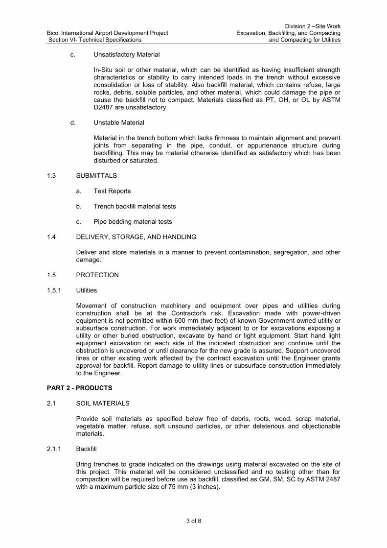
c. Unsatisfactory Material
In-Situ soil or other material, which can be identified as having insufficient strength characteristics or stability to carry intended loads in the trench without excessive consolidation or loss of stability. Also backfill material, which contains refuse, large rocks, debris, soluble particles, and other material, which could damage the pipe or cause the backfill not to compact. Materials classified as PT, OH, or OL by ASTM D2487 are unsatisfactory.
d. Unstable Material
Material in the trench bottom which lacks firmness to maintain alignment and prevent joints from separating in the pipe, conduit, or appurtenance structure during backfilling. This may be material otherwise identified as satisfactory which has been disturbed or saturated.
1.3 SUBMITTALS
a. Test Reports
b. Trench backfill material tests
c. Pipe bedding material tests
1.4 DELIVERY, STORAGE, AND HANDLING
Deliver and store materials in a manner to prevent contamination, segregation, and other damage.
1.5 PROTECTION
1.5.1 Utilities
Movement of construction machinery and equipment over pipes and utilities during construction shall be at the Contractor's risk. Excavation made with power-driven equipment is not permitted within 600 mm (two feet) of known Government-owned utility or subsurface construction. For work immediately adjacent to or for excavations exposing a utility or other buried obstruction, excavate by hand or light equipment. Start hand light equipment excavation on each side of the indicated obstruction and continue until the obstruction is uncovered or until clearance for the new grade is assured. Support uncovered lines or other existing work affected by the contract excavation until the Engineer grants approval for backfill. Report damage to utility lines or subsurface construction immediately to the Engineer.
PART 2 - PRODUCTS
2.1 SOIL MATERIALS
Provide soil materials as specified below free of debris, roots, wood, scrap material, vegetable matter, refuse, soft unsound particles, or other deleterious and objectionable materials.
2.1.1 Backfill
Bring trenches to grade indicated on the drawings using material excavated on the site of this project. This material will be considered unclassified and no testing other than for compaction will be required before use as backfill, classified as GM, SM, SC by ASTM 2487 with a maximum particle size of 75 mm (3 inches).
Division 2 –Site Work Bicol International Airport Development Project Excavation, Backfilling, and Compacting Section VI- Technical Specifications and Compacting for Utilities
4 of 8
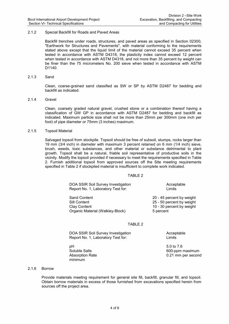
2.1.2 Special Backfill for Roads and Paved Areas
Backfill trenches under roads, structures, and paved areas as specified in Section 02300, "Earthwork for Structures and Pavements", with material conforming to the requirements stated above except that the liquid limit of the material cannot exceed 35 percent when tested in accordance with ASTM D4318, the plasticity index cannot exceed 12 percent when tested in accordance with ASTM D4318, and not more than 35 percent by weight can be finer than the 75 micrometers No. 200 sieve when tested in accordance with ASTM D1140.
2.1.3 Sand
Clean, coarse-grained sand classified as SW or SP by ASTM D2487 for bedding and backfill as indicated.
2.1.4 Gravel
Clean, coarsely graded natural gravel, crushed stone or a combination thereof having a classification of GW GP in accordance with ASTM D2487 for bedding and backfill as indicated. Maximum particle size shall not be more than 25mm per 300mm (one inch per foot) of pipe diameter or 75mm (3 inches) maximum.
2.1.5 Topsoil Material
Salvaged topsoil from stockpile. Topsoil should be free of subsoil, stumps, rocks larger than 19 mm (3/4 inch) in diameter with maximum 3 percent retained on 6 mm (1/4 inch) sieve, brush, weeds, toxic substances, and other material or substance detrimental to plant growth. Topsoil shall be a natural, friable soil representative of productive soils in the vicinity. Modify the topsoil provided if necessary to meet the requirements specified in Table 2. Furnish additional topsoil from approved sources off the Site meeting requirements specified in Table 2 if stockpiled material is insufficient to complete work indicated.
TABLE 2 DOA SSIR Soil Survey Investigation Acceptable Report No. 1, Laboratory Test for: Limits Sand Content 20 - 45 percent by weight Silt Content 25 - 50 percent by weight Clay Content 10 - 30 percent by weight Organic Material (Walkley-Block) 5 percent
TABLE 2 DOA SSIR Soil Survey Investigation Acceptable Report No. 1, Laboratory Test for: Limits pH 5.0 to 7.6 Soluble Salts 600-ppm maximum Absorption Rate 0.21 mm per second minimum
2.1.6 Borrow
Provide materials meeting requirement for general site fill, backfill, granular fill, and topsoil. Obtain borrow materials in excess of those furnished from excavations specified herein from sources off the project area.

Division 2 –Site Work Bicol International Airport Development Project Excavation, Backfilling, and Compacting Section VI- Technical Specifications and Compacting for Utilities
5 of 8
2.1.7 Pipe Bedding
Provide material for pipe bedding consisting of GW GP GM GC SW SP SM SC sand gravel as classified in accordance with ASTM D2487.
2.2 CONCRETE PIPE CRADLES
Concrete pipe cradles where indicated conforming to lines and dimensions indicated. Construct cradles with concrete having a 28 day compressive strength of 20.7 MPa (3000 psi).
PART 3 - EXECUTION 3.1 PROTECTION 3.1.1 Drainage and Dewatering
a. Drainage
Surface water shall be directed away from excavation and construction sites so as to prevent erosion and undermining of foundations. Diversion ditches, and grading shall be provided and maintained as necessary during construction. Excavated slopes and backfill surfaces shall be protected to prevent erosion and sloughing. Excavation shall be performed so that the site and the area immediately surrounding the site and affecting operations at the site shall be continually and effectively drained.
3.1.2 Dewatering
Groundwater flowing toward or into excavations shall be controlled to prevent sloughing of excavation slopes and walls, boils, uplift and heave in the excavation and to eliminate interference with orderly progress of construction. Control measures shall be taken by the time the excavation reaches the water level in order to maintain the integrity of the in situ material. Operate the dewatering system until construction work below existing water levels is complete.
3.1.3 Underground Utilities
The Contractor shall physically verify the location and elevation of the existing utilities prior to starting construction. The Contractor shall mark the surface of the ground where existing underground utilities are discovered.
3.1.4 Structures and Surfaces
Protect newly backfilled areas slopes, or grades from traffic, erosion settlement, or any other damage. Repair and reestablish damaged or eroded grades and slopes and restore surface construction prior to acceptance. Protect existing streams, ditches, and storm drain inlets from water-borne soil.
3.3 SURFACE PREPARATION
3.3.1 Stockpiling Topsoil
Strip suitable soil from the site where excavation or grading is indicated and stockpile separately from other excavated material. Material unsuitable for use as topsoil shall be wasted. Locate topsoil so that the material can be used readily for the finished grading. Where sufficient existing topsoil conforming to the material requirements is not available on site, provide borrow materials suitable for use as topsoil. Protect topsoil and keep in segregated piles until needed.
Division 2 –Site Work Bicol International Airport Development Project Excavation, Backfilling, and Compacting Section VI- Technical Specifications and Compacting for Utilities
6 of 8
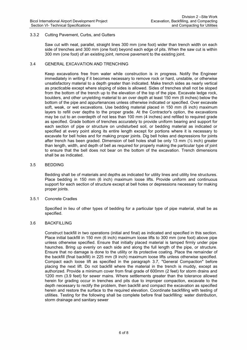
3.3.2 Cutting Pavement, Curbs, and Gutters
Saw cut with neat, parallel, straight lines 300 mm (one foot) wider than trench width on each side of trenches and 300 mm (one foot) beyond each edge of pits. When the saw cut is within 300 mm (one foot) of an existing joint, remove pavement to the existing joint.
3.4 GENERAL EXCAVATION AND TRENCHING
Keep excavations free from water while construction is in progress. Notify the Engineer immediately in writing if it becomes necessary to remove rock or hard, unstable, or otherwise unsatisfactory material to a depth greater than indicated. Make trench sides as nearly vertical as practicable except where sloping of sides is allowed. Sides of trenches shall not be sloped from the bottom of the trench up to the elevation of the top of the pipe. Excavate ledge rock, boulders, and other unyielding material to an over depth at least 150 mm (6 inches) below the bottom of the pipe and appurtenances unless otherwise indicated or specified. Over excavate soft, weak, or wet excavations. Use bedding material placed in 150 mm (6 inch) maximum layers to refill over depths to the proper grade. At the Contractor's option, the excavations may be cut to an overdepth of not less than 100 mm (4 inches) and refilled to required grade as specified. Grade bottom of trenches accurately to provide uniform bearing and support for each section of pipe or structure on undisturbed soil, or bedding material as indicated or specified at every point along its entire length except for portions where it is necessary to excavate for bell holes and for making proper joints. Dig bell holes and depressions for joints after trench has been graded. Dimension of bell holes shall be only 13 mm (½ inch) greater than length, width, and depth of bell as required for properly making the particular type of joint to ensure that the bell does not bear on the bottom of the excavation. Trench dimensions shall be as indicated.
3.5 BEDDING
Bedding shall be of materials and depths as indicated for utility lines and utility line structures. Place bedding in 150 mm (6 inch) maximum loose lifts. Provide uniform and continuous support for each section of structure except at bell holes or depressions necessary for making proper joints.
3.5.1 Concrete Cradles
Specified in lieu of other types of bedding for a particular type of pipe material, shall be as specified.
3.6 BACKFILLING
Construct backfill in two operations (initial and final) as indicated and specified in this section. Place initial backfill in 150 mm (6 inch) maximum loose lifts to 300 mm (one foot) above pipe unless otherwise specified. Ensure that initially placed material is tamped firmly under pipe haunches. Bring up evenly on each side and along the full length of the pipe, or structure. Ensure that no damage is done to the utility or its protective coating. Place the remainder of the backfill (final backfill) in 225 mm (9 inch) maximum loose lifts unless otherwise specified. Compact each loose lift as specified in the paragraph 3.7, "General Compaction" before placing the next lift. Do not backfill where the material in the trench is muddy, except as authorized. Provide a minimum cover from final grade of 600mm (2 feet) for storm drains and 1200 mm (3.9 feet) for sewer mains. Where settlements greater than the tolerance allowed herein for grading occur in trenches and pits due to improper compaction, excavate to the depth necessary to rectify the problem, then backfill and compact the excavation as specified herein and restore the surface to the required elevation. Coordinate backfilling with testing of utilities. Testing for the following shall be complete before final backfilling: water distribution, storm drainage and sanitary sewer

Division 2 –Site Work Bicol International Airport Development Project Excavation, Backfilling, and Compacting Section VI- Technical Specifications and Compacting for Utilities
7 of 8
3.7 COMPACTION
Use hand-operated, plate-type, vibratory, or other suitable hand tampers in areas not accessible to larger rollers or compactors. Avoid damaging pipes and protective pipe coatings. Compact material in accordance with the following unless otherwise specified. If necessary, alter, change, or modify selected equipment or compaction methods to meet specified compaction requirements.
3.7.1 Compaction of Material in Subcuts or Over excavations
In rock, compact to 95 percent of ASTM D1557 maximum density. In soft, weak, or wet soils, tamp refill material to consolidate to density of adjacent material in trench wall. In stable soils, compact to 90 percent of ASTM D1557maximum density.
3.7.2 Compaction of Pipe and Conduit Bedding
In rock, compact to 95 percent and in soil, compact to 90 percent of ASTM D1557 maximum density.
3.7.3 Compaction of Backfill
Compact initial backfill material surrounding pipes, or conduits, to 90 percent of ASTM D1557 maximum density except where bedding and backfill are the same material. Where bedding and backfill are the same material, compact initial backfill to the density of the bedding. Under areas to be seeded or sodded, compact succeeding layers of final backfill to 85 percent of ASTM D1557 maximum density. For utilities under road or highway right-of-way, structures and pavements compact layers of final backfill as specified under paragraph 3.8, "Special Earthwork Installation Requirements."
3.8 SPECIAL EARTHWORK INSTALLATION REQUIREMENTS
3.8.1 Concrete Culvert Piping Under Embankment
Construct the embankment to 150 mm (6 inches) above elevation of top of pipe for 600 mm (24 inch) size pipe and to 750 mm (30 inches) above elevation of top of pipe where the pipe diameter is larger than 600mm (24 inches). After pipe installation, backfill and compact in accordance with requirements stated in paragraphs 3.6, "Backfilling and 3.7, “Compaction."
3.8.2 Manholes and Other Appurtenances
Provide at least 300 mm (12 inches) clear from outer surfaces to the embankment or shoring. Remove rock as specified herein. Remove unstable soil that is incapable of supporting the structure to an overdepth of 300 mm (one foot) and refill with gravel or sand to the proper elevation. Stabilize soft, weak, or wet excavations as indicated. Refill over depths with gravel or sand to the required grade and compact to 90 percent of ASTM D1557 maximum density.
3.8.3 Compaction under Roads, Streets, and other Areas to be paved
Place final backfill in 150 mm (6 inch) maximum loose lifts. If a vibratory roller is used for compaction of final backfill, the lift thickness can be increased to 225 mm (9 inches). Compact all backfill surrounding pipes, conduits, and other structures to 90 percent of ASTM D1557 maximum density except compact the top 300 mm (12 inches) of subgrade to 95 percent of ASTM D1557 maximum density. Backfill to permit the rolling and compacting of the completed excavation with the adjoining material, providing the specified density necessary to enable paving of the area immediately after backfilling has been completed. Compaction requirements for materials in pavement sections above the subgrade level shall be as specified in Section 02300, "Earthwork for Structures and Pavement."

Division 2 –Site Work Bicol International Airport Development Project Excavation, Backfilling, and Compacting Section VI- Technical Specifications and Compacting for Utilities
8 of 8
3.9 FINISH OPERATIONS
3.9.1 Grading
Finish to grades indicated within 30 mm (one-tenth of a foot). Grade areas to drain water away from structures. Grade existing grades that are to remain but have been disturbed by the Contractor's operations.
3.9.2 Spreading Topsoil
Clear areas to receive topsoil for the finished surface of materials that would interfere with planting and maintenance operations. Scarify subgrade to a depth of 50 mm (2 inches). Do not place topsoil when the subgrade is extremely wet or dry, or in other conditions detrimental to seeding, planting, or grading. Spread topsoil to a uniform depth of 100 mm (4 inches) over the designated areas.
3.9.3 Disposition of Surplus Material
Surplus or other soil material not required or suitable for filling, backfilling, or grading shall be wasted by disposition off the work site.
3.9.4 Protection of Surfaces
Protect newly graded areas from traffic, erosion, and settlements that may occur. Repair or reestablish damaged grades, elevations, or slopes.
3.10 FIELD QUALITY CONTROL
Test sand, gravel, bedding, backfill and topsoil for conformance to specified requirements. Test backfill to be used under roads and paved areas for conformance to special requirements. Test bedding and backfill for moisture-density relations in accordance with ASTM D1557 and as specified herein. Perform at least one of each of the required tests for each material provided. Perform sufficiently in advance of construction so as not to delay work. Provide additional tests as specified above for each change of source. Perform final tests on topsoil to ensure adjustment of parameters into the ranges specified. Perform density and moisture tests in randomly selected locations and in accordance with ASTM D1556, ASTM D2922 and ASTM D3017 as follows:
a. Bedding and backfill in trenches: One test per 15 meters
(50 linear feet) in each lift.
b. Appurtenance structures: One test per 9 square meters
(100 square feet) or fractions thereof in each lift.
Where ASTM D2922 and ASTM D3017 are used to test field compaction densities, verify test results by performing at least one test per day using ASTM D1556 at a location already tested in accordance with ASTM D2922. Perform at least one additional test using ASTM D1556 for every ten tests performed with a nuclear device, at locations checked in accordance with ASTM D2922.
******
Bicol International Airport Development Project Division 2 – Site Work Section VI- Technical Specifications Soil Treatment for Subterranean Termite Control
1 of 3
SECTION 02360 - SOIL TREATMENT FOR SUBTERRANEAN TERMITE CONTROL
PART 1 - GENERAL 1.1 SUBMITTALS
Submit the following:
a. Samples
(1) Pesticides: Submit on request, or may draw at any time and without prior notice, from stocks at the job site, samples of the pesticides used in this work. Should analysis, indicate such samples to contain less than the amount of active ingredient specified on the label, work performed with such products shall be repeated, with pesticides conforming to this specifications, at no additional cost to the Owner.
b. Qualifications of pesticides applicators: Submit data as required in the paragraph 1.2,
“Qualifications of Pesticide Applicators”, prior to commencement of work.
c. Manufacturer’s Instructions
(1) Pesticides: Submit a copy of manufacturer’s label.
d. Closeout Submittals
(1) Warranty (2) Application report (3) Submit documents signed and sealed by an officer of the Contractor
1.2 QUALIFICATIONS OF PESTICIDE APPLICATORS
The pesticide applicator’s principal business shall be pest control and the pesticide applicator shall be certified pesticide applicator.
1.3 DELIVERY, STORAGE AND HANDLING
Deliver pesticides to the project site in sealed and labeled containers in good condition as supplied by the manufacturer or formulator. Store, handle and use pesticides in accordance with manufacturer’s labels. Labels shall bear evidence of registration.
1.4 SAFETY REQUIREMENTS
Formulate, treat and dispose of termiticides and their containers in accordance with label directions. Draw water for formulating only from sites designated by the Owner’s representative and fit the filing hose with backflow preventer meeting local plumbing codes or standards. The filling operation shall be under the direct and continuous observation of a Contractor’s Representative to prevent overflow. Secure pesticides and related materials under lock and key when unattended. Ensure that proper protective clothing and equipment are worn and used during all phases of termiticide operation. Dispose of used pesticide containers off the project site.

Bicol International Airport Development Project Division 2 – Site Work Section VI- Technical Specifications Soil Treatment for Subterranean Termite Control
2 of 3
1.5 WARRANTY
Furnish a three year written warranty against infections or reinfestations by subterranean termite of the building constructed under this contract. Perform annual inspections of the building. If live subterranean termite infestation or subterranean termite damage is discovered during the warranty period, and the soil and building conditions have not been altered in the interim, the Contractor shall:
a. Retreat the soil and perform other treatment as may be necessary for the elimination
of subterranean termite infestation.
b. Repair damage caused by termite infestation; and
c. Re-inspect the building approximately 180 days after the re-treatment. 1.6 QUALITY ASSURANCE
a. Application Report: Upon completion of this work, submit report identifying the type of operation, brand name and manufacturer of pesticide, formulation, concentration or rate of application used. Maintain daily records and submit copies of records when requested by the Owner’s Representative.
PART 2 - PRODUCTS 2.1 PESTICIDES
Termiticides bearing currently approved for such use by the appropriate agency. PART 3 - EXECUTION
3.1 VERIFICATION OF CONDITIONS
At the time of application, the soil shall have a sufficiently low moisture content to allow uniform distribution of the treatment solution throughout the soil. Do not make applications during or immediately following heavy rains or when conditions may cause runoff and create an environment hazard.
3.2 APPLICATION
a. Treatment Area: Apply termiticide to soil material which will be covered by or lie immediately adjacent to the buildings and structures so as to provide a protective barrier against subterranean termites.
b. Treatment Application: Apply termiticide as a coarse spray and in such manner as to
provide uniform distribution onto the soil surface. Apply treatment prior to placement of a vapor barrier or waterproof membrane and at least 12 hours prior to concrete pouring. Where treated soil or fill material is not to be covered with a vapor barrier or waterproof membrane, exercise adequate precautions to prevent its disturbance. If soil or fill material has been disturbed after treatment, retreat as specified above before placement of slab or other covering structure. Coordinate treatment of the soil on the exterior sides of foundation walls, grade beams and similar structure with final grading and planting operations so as to avoid disturbance of the treated barriers by such operations. Observe manufacturer’s warnings and precautions in the handling and use of such materials. Exercise precaution that these chemicals do not enter water supply systems or potable water supplies or aquafiers, and that they do not endanger plants as well.

Bicol International Airport Development Project Division 2 – Site Work Section VI- Technical Specifications Soil Treatment for Subterranean Termite Control
3 of 3
Notify the Owner’s Representative at least 48 hours prior to beginning of treatment and perform formulating, mixing and application in the presence of Owner’s Representative.
c. Rates and Methods of Application: Apply in accordance with the pesticide label.
Provide maximum application or dosage rates. Resolve conflict between this specification and the label direction in favor of the label.
4.0 METHOD OF MEASUREMENT
Soil Treatment or Termite Control shall be measured by the number of square meters applied and accepted.
5.0 BASIS OF PAYMENT
The accepted quantity measured as prescribed in Method of Measurement shall be paid for at the contract unit price for Soil Treatment or Termite Control which price and payment shall be full compensation for furnishing and placing all materials, including labor, equipment, tools and incidentals necessary to complete the work prescribed in this Section.
Payment will be made in accordance with the Bill of Quantities.
******

DIVISION 3

BBiiccooll IInntteerrnnaattiioonnaall AAiirrppoorrtt DDeevveellooppmmeenntt PPrroojjeecctt DDiivviissiioonn 33 -- CCoonnccrreettee SSeeccttiioonn VVII-- TTeecchhnniiccaall SSppeecciiffiiccaattiioonnss CCaasstt--IInn--PPllaaccee CCoonnccrreettee
1 of 18
SECTION 03300 - CAST-IN-PLACE CONCRETE
PART 1 - GENERAL
1.1 Applicable Publications
The publications listed below form a part of this specification to the extent referenced. The publications are referred to in the text by the basic designation only. Unless specified, all publications below shall be of the latest edition.
1.1.1 American Concrete Institute (ACI) Publications:
ACI 224 R Control of Cracking in Concrete Structures
ACI 301 Specifications for Structural Concrete for Buildings ACI 302.1 R Guide for Concrete Floor and Slab Construction
ACI 304 Recommended Practice for Measuring, Mixing,
Transporting and Placing Concrete
ACI-305R Hot-Weather Concreting
ACI 315 Details and Detailing of Concrete Reinforcement
ACI 318R Building Code Requirements for Reinforced Concrete
ACI 347-R Recommended Practice for Concrete Formwork
ACI 350R Environmental Engineering Concrete Structures
1.1.2 American Society for Testing and Materials (ASTM) Publications:
C 39 Compressive Strength of Cylindrical Concrete Specimens
C 94 Ready-Mixed Concrete
C920 Elastomeric Joint Sealants
C 138 Test Methods for Unit Weight, Yield and Air Content (Gravimetric) or Concrete
C 231 Standard Test Method for Air Content of Freshly-Mixed Concrete by the Pressure Method
C 173 Standard Test Method for Air Content of Freshly-Mixed Concrete by the Volumetric Method
D 1751 Preformed Expansion Joint Fillers for Concrete Paving and Structural Construction (Non-extruding and Resilient Bituminous Types)
1.1.3 American Welding Society (AWS) Publication:
D1.4 Structural Welding Code-Reinforcing Steel

BBiiccooll IInntteerrnnaattiioonnaall AAiirrppoorrtt DDeevveellooppmmeenntt PPrroojjeecctt DDiivviissiioonn 33 -- CCoonnccrreettee SSeeccttiioonn VVII-- TTeecchhnniiccaall SSppeecciiffiiccaattiioonnss CCaasstt--IInn--PPllaaccee CCoonnccrreettee
2 of 18
1.1.4 Product Standards Agency (PSA) Publications:
a. Philippine National Standards:
PNS 07 Specifications for Portland Cement
PNS 18 Specifications for Concrete Aggregates
PNS 49 Specifications for Steel Bars for Concrete Reinforcement
b. Standards Administrative Order (SAO)
SAO-6 Philippine Plywood
1.2 Description of Work
The work includes the provision of cast-in-place concrete. In the ACI publications referred to herein, the advisory provisions shall be considered to be mandatory, as though the word "shall" has been substituted for "should" wherever it appears.
1.3 Submittals:
1.3.1 Shop Drawings
Reproductions of contract drawings are unacceptable.
a. Shop Drawings for Reinforcing Steel: ACI 315. Indicate bending diagrams, assembly diagrams, splicing and laps of bars, shapes, dimensions, and details of bar reinforcing, accessories, and concrete cover.
Do not scale dimensions from structural drawings to determine lengths of reinforcing rods.
b. Shop Drawings for Formwork: ACI 347. Include design calculations indicating arrangement of forms, sizes and grade of supports (lumber), panels, and related components. Indicate placement schedule, construction, and location and method of forming control joints. Include locations of inserts, pipework, conduit, sleeves, and other embedded items. Furnish drawings and descriptions of shoring and reshoring methods, proposed for suspended slab, spandrel beams, and other horizontal concrete members. Furnish schedule of form removal of structures not included in paragraph 3.5.5 “Removal of Forms”.
c. Shop Drawings for Construction Joints: ACI 318. Drawings shall clearly indicate sequence of pouring for all footings, columns, beams and slabs.
1.3.2 Contractor Mix Design: Thirty days minimum prior to concrete placement, submit a mix design for each strength and type of concrete. Furnish a complete list of materials including type; brand; source and amount of cement and admixtures; applicable reference specifications; and copies of test reports showing that the mix has been successfully tested to produce concrete with the properties specified and will be suitable for the job conditions. Submit additional data regarding concrete aggregates if the source of aggregate changes.
1.3.3 Certified Laboratory Test Reports: Before delivery of materials, certified copies in 5 copies of the reports of all tests required in referenced publications or otherwise specified herein shall be submitted to and approved by the Owner’s Representative. The testing shall have been performed within one year of submittal of the test reports for approval by an independent laboratory approved by the Owner's Representative. Test reports on a previously tested

BBiiccooll IInntteerrnnaattiioonnaall AAiirrppoorrtt DDeevveellooppmmeenntt PPrroojjeecctt DDiivviissiioonn 33 -- CCoonnccrreettee SSeeccttiioonn VVII-- TTeecchhnniiccaall SSppeecciiffiiccaattiioonnss CCaasstt--IInn--PPllaaccee CCoonnccrreettee
3 of 18
materials shall be accompanied by notarized certificates from the manufacturer certifying that the previously tested material is of the same type, quality, manufacture, and make as that proposed for use in this project. Certified test reports are required for the following:
a. Aggregates b. Reinforcement c. Cement
1.3.4 Certificates of Compliance:
a. Materials for Curing Concrete b. Joint filler c. Vapor barrier d. Admixtures
1.3.5 Catalog Data:
a. Materials for curing concrete b. Joint filler c. Vapor barrier d. Admixtures
1.4 DELIVERY AND STORAGE:
1.4.1 Cement
Cement in bags shall be stored in a suitable weatherproof structure which shall be as air-tight as practicable; floors shall be elevated above the ground a distance sufficient to prevent the absorption of moisture. Bags shall be stacked close together to reduce circulation of air but shall not be stacked against outside walls; the manner of storage shall permit easy access for inspection and identification of each shipment. Bulk cement shall be transferred to elevated airtight and weatherproof bins. At the time of use all cement shall be free-flowing and free of lumps. Cement that has been in storage longer than 6 months will be tested by standard mortar tests or other tests as deemed necessary by the Owner's Representative to determine its suitability for use and such cement shall not be used without approval of the Owner's Representative.
1.4.2 Aggregates
Aggregates shall be stored on areas covered with tightly laid wood planks, sheet metal, or other hard and clean surface, and in a manner that will preclude the inclusion of foreign material. Aggregates of different sizes shall be stored in separate piles. Stock piles of coarse aggregate shall be built in horizontal layers not exceeding 1.20 meters in depth to minimize segregation. Should the coarse aggregate become aggregated it shall be remixed to conform to the grading requirements.
1.4.3 Reinforcement
Store reinforcement of different sizes in racks raised above the ground with accurate identification. Protect reinforcing steel from contaminants such as grease, oil, and dirt.
1.4.4 Admixtures
Admixtures shall be stored in a manner that will not damage the containers.

BBiiccooll IInntteerrnnaattiioonnaall AAiirrppoorrtt DDeevveellooppmmeenntt PPrroojjeecctt DDiivviissiioonn 33 -- CCoonnccrreettee SSeeccttiioonn VVII-- TTeecchhnniiccaall SSppeecciiffiiccaattiioonnss CCaasstt--IInn--PPllaaccee CCoonnccrreettee
4 of 18
PART 2 - PRODUCTS
2.1 CONCRETE
2.1.1 Contractor-Furnished Mix Design
ACI 211.1 and ACI 301. Unless indicated otherwise on the drawings, the following shall apply: ________________________________________________________________________
28-Day
Compressive Maximum Agg. Slump
Strength Size (mm) (mm)
Location (MPa) (kg/sq.cm.)
________________________________________________________________________
Slabs, Footings 21.0 210 20 27-75
All Others 28.0 210 25 27.75
__________________________________________________________________________
2.2 MATERIALS
2.2.1 Cement
ASTM C150, Type I Portland Cement
2.2.2 Water
Water shall be fresh, clean, and potable.
2.2.3 Aggregates
ASTM C33, except as modified herein. Obtain aggregates for exposed concrete surfaces from one source. Aggregates shall not contain any substance which may be deleteriously reactive with the alkalies in the cement.
2.2.4 Non-shrink Grout
ASTM C 827 non-metallic.
2.2.5 Admixtures
a. Accelerating: ASTM C 494, Type C.
b. Retarding: ASTM C 494, Type B or D.
c. Water Reducing: ASTM C 494, Type A or E.
d. Air entraining, ASTM C 260
Percentage of air content shall be as required in ACI 318, ACI 201.2R and ASTM C 1116, as applicable.
BBiiccooll IInntteerrnnaattiioonnaall AAiirrppoorrtt DDeevveellooppmmeenntt PPrroojjeecctt DDiivviissiioonn 33 -- CCoonnccrreettee SSeeccttiioonn VVII-- TTeecchhnniiccaall SSppeecciiffiiccaattiioonnss CCaasstt--IInn--PPllaaccee CCoonnccrreettee
5 of 18
e. Materials for Forms
Provide wood, plywood, or steel. Use plywood or steel forms where a smooth form finish is required. Lumber shall be square edged or tongue-and-groove boards, free of raised grain, knotholes, or other surface defects. Plywood shall conform with SAO 6, Type I, Grade A or better surfaces. Steel form surfaces shall not contain irregularities, dents, or sags.
2.2.7 Reinforcement
a. Reinforcing Bars
ASTM A 615 (Weldable). All reinforcing steel shall be deformed. Reinforcing steel shall have a minimum yield strength of 275 MPa (Grade 40) for bars dia. 12mm and smaller, and 414 MPa (Grade 60) for bars dia. 16 and larger.
2.2.8 Vapor Barrier
ASTM C 171 polyethylene sheeting, minimum 6 mil thickness.
2.2.9 Materials for Curing Concrete
a. Impervious Sheeting: ASTM C 171; waterproof paper, clear or white polyethylene sheeting, or polyethylene-coated burlap.
b. Pervious Sheeting: AASHTO M 182.
c. Liquid Membrane-Forming Compound: ASTM C 309, white-pigmented, Type 2, Class B, free of paraffin or petroleum.
d. Liquid Chemical Sealer-Hardener Compound: Compound shall not contain petroleum resins or waxes. Compound shall not reduce the adhesion of resilient flooring, tile, paint, waterproofing, or other material applied to concrete.
e. Expansion/Contraction Joint Filler: ASTM D 1751 or ASTM D1752.
f. Joint Sealants
g. Horizontal Surfaces (3 percent slope, maximum):
(1) Outside Buildings: ASTM D 1190.
(2) Inside Buildings: ASTM D 1190 or ASTM D 1850.
(3) Vertical Surfaces (greater than 3 percent slope): ASTM C 920, Type M, Grade NS, Class 25, Use T.
(4) Forms: ACI 301
(5) General Requirements
Forms shall be provided for all concrete not indicated or specified otherwise. Forms shall be set true to line and grade and maintained so as to insure completed work within the allowable tolerance specified, and shall be mortar-tight. The Contractor shall be responsible for the adequacy of forms and form supports. Bolts and rods used for internal ties shall be arranged so that when the forms are removed, all metals will have concrete cover not

BBiiccooll IInntteerrnnaattiioonnaall AAiirrppoorrtt DDeevveellooppmmeenntt PPrroojjeecctt DDiivviissiioonn 33 -- CCoonnccrreettee SSeeccttiioonn VVII-- TTeecchhnniiccaall SSppeecciiffiiccaattiioonnss CCaasstt--IInn--PPllaaccee CCoonnccrreettee
6 of 18
less than that indicated in the drawings. Bolts or rod type form ties that must be removed when forms are removed shall not be used for watertight forms. Wire tire shall not be used where the concrete surface will be exposed to weathering and where discoloration will be exposed. All form work shall be provided with adequate clean-out openings to permit inspection and easy cleaning after all reinforcement has been placed. Where forms for continuous surfaces are placed in successive units, the forms shall be fitted over the completed surface to obtain accurate alignment of the surface and to prevent leakage of mortar. Panel forms shall be constructed to provide tight joints between panels. All forms shall be constructed so that they can be removed without damaging the concrete. All exposed joints, edges, and external corners shall be chamfered a minimum of 20 mm unless specified otherwise herein. Forms for heavy girders and similar members shall be constructed with a proper camber as indicated.
f. Materials for Forms
Forms shall be of wood, plywood, or steel. Wood forms for surfaces exposed to view in the finished structure and requiring a smooth form finish, shall be plywood. For unexposed surfaces, undressed square-edge lumber may be used. Forms for surfaces requiring special finishes shall be plywood, or shall be lined with plywood, a non-absorptive, hard-pressed fiberboard, absorptive-type lining or other suitable material. Plywood, other than for lining, shall be concrete-form plywood not less than 16 mm thick free of raised grain, torn surfaces, worn edges, patches, or other surface defects which would impair the texture of the concrete surface. Surfaces of steel forms shall be free from irregularities, dents, and sags.
g. Coating
Before placing the concrete, the contact surfaces of forms shall be coated with a non-staining mineral oil or suitable non-staining form coating compound or shall be given two coats of nitrocellulose lacquer, except as specified otherwise. Mineral oil shall not be used on forms for surfaces which are to be painted. For surfaces not exposed to view in the finished structure, sheathing may be wetted thoroughly with clean water. All excess coating shall be removed by wiping with cloths. Reused forms shall have the contact surfaces cleaned thoroughly; those which have been coated shall be given an additional application of the coating. Plaster waste molds shall be sized with two coats of thin shellac or lacquer and coated with soft or thinned non-staining grease.
h. Tolerance and Variations
The Contractor shall set and maintain concrete forms to ensure that, after removal of the forms and prior to patching and finishing, no portion of the concrete work will exceed any of the tolerances specified. Variations in floor levels shall be measured before removal of supporting shores. The Contractor shall be responsible for variations due to deflection, when the latter results from concrete quality or curing other than that which has been specified. The tolerances specified shall not be exceeded by any portion of any concrete surfaces; the specified variation for one element of the structure will not be applicable when it will permit another element of the structure to exceed its allowable variations except as otherwise specified herein, tolerances shall conform to ACI 347.

BBiiccooll IInntteerrnnaattiioonnaall AAiirrppoorrtt DDeevveellooppmmeenntt PPrroojjeecctt DDiivviissiioonn 33 -- CCoonnccrreettee SSeeccttiioonn VVII-- TTeecchhnniiccaall SSppeecciiffiiccaattiioonnss CCaasstt--IInn--PPllaaccee CCoonnccrreettee
7 of 18
PART 3 - EXECUTION
3.1 PROPORTIONING, MEASUREMENT AND MIXING
ASTM, C94, ACI 301, ACI 302.1R, and ACI 304, except as modified herein.
3.1.1 Proportioning of Materials
Proportioning of materials shall be accomplished by weighing, except as otherwise provided herein. In urgent situations, volumetric proportioning may be used temporarily, if permitted by the Owner's Representative, who will stipulate the length of the period during which volumetric proportioning may be used. The Contractor shall furnish the necessary equipment and shall establish accurate procedures for determining the quantities of free moisture in the aggregates, the true volume of the fine aggregate if volumetric proportioning is used, and the air content of the freshly mixed concrete if air-entrained concrete is used. Moisture, volumetric, and air determinations shall be made at intervals as directed by the Owner's Representative as specified herein under Sampling and testing requirements. Allowable tolerances for measuring cement and water shall be one percent; for aggregates 2 percent and for admixtures 3 percent.
a. Weight Measurement
The fine aggregate and each size of coarse aggregate shall be weighed separately. Cement in standard packages shall be weighed on a scale separate from that used for weighing the other materials.
b. Volumetric Measurement
The weight proportions shall be transposed into equivalent volumetric proportions by weighing representative samples of the aggregates in the condition in which they will be measured and in accordance with ASTM C 29. In determining the true volume of the fine aggregate, allowance shall be made for the bulking effect from the moisture contained therein. Suitable allowances shall also be made for variations in the moisture conditions of the aggregates.
3.1.2 Mixing
All concrete shall be machine mixed. In emergencies, the mixing may be done by hand if so authorized by the Owner's Representative. Mixing shall begin within 30 minutes after the cement has been added to the aggregates. The time of mixing after all cement and aggregates are in the mixer drum shall be not less than one minute for mixers having a capacity of one cubic yard or less; for mixers of larger capacities, the minimum time shall be increased 15 seconds for each additional cubic yard or fraction thereof of additional capacity. A reduction in the aforementioned mixing time shall be permitted in accordance with ASTM C 94 if mixer performance tests made at the Contractor's option and at his expense, indicate adequate mixing with the reduced time. All mixing water shall be introduced in the drum before one-fourth of the mixing time has elapsed. The entire contents of the mixer drum shall be discharged before recharging. The time elapsing between the introduction of the mixing water to the cement and aggregates or the cement to the aggregates and placing of the concrete in final position in the forms shall not exceed 60 minutes if the air temperature is less than 30 degrees C and 45 minutes if the air temperature is equal or greater than 30 degrees C. The retempering of concrete, i.e., remixing with or without additional cement, aggregate, or water, is not permitted.
BBiiccooll IInntteerrnnaattiioonnaall AAiirrppoorrtt DDeevveellooppmmeenntt PPrroojjeecctt DDiivviissiioonn 33 -- CCoonnccrreettee SSeeccttiioonn VVII-- TTeecchhnniiccaall SSppeecciiffiiccaattiioonnss CCaasstt--IInn--PPllaaccee CCoonnccrreettee
8 of 18
3.1.3 Ready Mixed Concrete
Ready-mixed concrete shall conform to ASTM C 94 as modified herein. Ready-mixed concrete is defined in this specification as concrete produced regularly by a commercial establishment and delivered to the purchaser in the plastic state. Ready-mixed concrete may be used provided that (a) the plant has sufficient capacity and transportation equipment to deliver the concrete at the rate desired, and (b) the plant meets the requirements specified herein for equipment, measurement of materials, and mixing, except as modified herein. The cement, aggregates, water and admixtures shall conform to all applicable requirements of this specification. Ready-mixed concrete not specified otherwise herein shall be mixed and delivered by one of the following methods.
a. Truck Mixing
Concrete shall be mixed and delivered in a truck mixer. Mixers shall be charged with a ribbon fed mixture of aggregates and cement, or in the absence of facilities for ribbon feeding, the aggregates shall be charged before the cement. When mixing is begun during or immediately after charging a portion of the mixing water not in excess of that required to produce the minimum acceptable slump, shall be added ahead of or with, the other ingredients. Total mixing shall be for not less than 50 nor more than 100 revolutions of the drum at the manufacturer's rated mixing speed after all ingredients including water are in the drum except as follows: After 30 to 75 revolutions of the drum the slump shall be tested and additional water shall be added if necessary to produce the required slump; if additional water is necessary, mixing shall be continued for at least 20 revolutions after the water is added. Mixing speed shall be not less than 16 rpm for open-top mixers, and not less than 4 rpm nor more than 16 rpm for open-top mixers. Any turning of the drum during transportation shall be at the speed designated by the manufacturer of the equipment, as agitating speed. Each batch of concrete delivered at the job site shall be accompanied by a time slip issued at the batching plant, bearing the time of departure therefrom and the signature of the inspector. Discharge of concrete from the drum shall be completed within one hour or before the drum completes 250 revolutions after the introduction of water to the cement and the aggregates.
b. Combination Central Plant and Truck Mixing (Shrink Mixing)
Concrete shall be partially mixed in a central plant mixer and the mixing completed in a truck mixer. The mixing time in a central-plant mixer shall be the minimum required to intermingle the ingredients and shall not exceed 30 minutes. The mixing shall be completed in a truck mixer as specified herein under truck mixing.
c. Central-Plant Mixing
Concrete shall be mixed completely in a stationary mixer at a plant and transported to the site of the work in a truck agitator or a truck mixer operating at a speed of rotation designated by the manufacturer as agitating speed. Mixing shall begin within 30 minutes after cement has been added to aggregates. When authorized in writing by the Owner's Representative, non-agitation equipment approved by him may be used for transporting concrete. The time lapse between the introduction of the mixing water to the cement and aggregates and the placing of concrete in final position in the forms, shall not exceed: (a) for agitating equipment - 60 minutes, air temperature less than 30 degrees C; (b) for non-agitating equipment - 30 minutes.
d. Consistency of Concrete
Slump shall be determined in accordance with ASTM C 143. Samples for slump determination shall be taken from the concrete during placing in the forms.

BBiiccooll IInntteerrnnaattiioonnaall AAiirrppoorrtt DDeevveellooppmmeenntt PPrroojjeecctt DDiivviissiioonn 33 -- CCoonnccrreettee SSeeccttiioonn VVII-- TTeecchhnniiccaall SSppeecciiffiiccaattiioonnss CCaasstt--IInn--PPllaaccee CCoonnccrreettee
9 of 18
3.2 PLACING REINFORCEMENT AND MISCELLANEOUS MATERIALS: ACI 301 3.2.1 General Requirements
All reinforcement bars, stirrups, hanger bars, wire fabric, spirals and other reinforcing materials shall be provided as indicated in the drawing or required by this specification, together with all necessary wire ties, chairs, spacers, supports and other devices necessary to install and secure the reinforcement properly. All reinforcement, when placed, shall be free from rust, scale, oil, grease, clay, and other coatings, and foreign substances that would reduce or destroy the bond. Rusting of reinforcement shall not reduce the effective cross sectional area of the reinforcement to the extent that the strength is reduced beyond specified values. Heavy, thick rust or loose, flaky rust shall be removed by rubbing with burlap or other approved method, prior to placing. Reinforcement which has bends not shown on the project drawings or on approved shop drawings, or is reduced in section by rusting such that its weight is not within permissible ASTM tolerances, shall not be used. All reinforcement shall be supported and wired together to prevent displacement by construction loads or by the placing of concrete. Unless directed otherwise by the Engineer, reinforcement shall not be bent after being partially embedded in hardened concrete. Detailing of reinforcing shall conform to ACI 315. Where cover over reinforcing steel is not specified or indicated it shall be in accordance with ACI 318.
3.2.2 Placing
Reinforcement shall be placed accurately and secured. It shall be supported by suitable chairs and spacers or by metal hangers. On the ground, and where otherwise subject to corrosion, concrete or other suitable non-corrodible material shall be used for supporting reinforcement. Where the concrete surface will be exposed to the weather in the finished structure or where rust would impair the appearance or finish of the structure, all reinforcement supports, within specified concrete cover, shall be galvanized or made of a suitable non-corrodible material.
3.2.3 Splicing of Reinforcement
Splicing of reinforcement shall be in accordance with ACI 318, except as indicated otherwise or modified herein. Where splices in addition to those indicated on the drawings are necessary, they shall be approved by the Owner's Representative prior to their use. Splices shall not be made in beams, girders, and slabs at points of maximum stress. Butt splicing shall preferably be used over lapping for bar sizes larger than 32 mm. Splices to be welded shall conform to AWS D 1.4; certification of weld ability of the reinforcement by the manufacturer, shall be submitted to the Owner's Representative. If the Contractor elects to use butt splicing of reinforcing, he shall submit complete details of the process to be used to the Owner's Representative. If butt splices are used the Contractor shall ensure that the splice meets the requirements specified herein by performing at least three splices which shall be submitted for tests to a testing laboratory that has been approved for such testing by the Owner's Representative. The cost of these shall be borne by the Contractor.
3.2.4 Moving Reinforcing Steel
All placement or movement of reinforcing steel after placement, to positions other than indicated or specified, shall be subject to the approval of the Owner's Representative.
3.2.5 Concrete Protection for Reinforcement
Concrete protection for reinforcement shall be as indicated; or if not indicated, in accordance with ACI 318.

BBiiccooll IInntteerrnnaattiioonnaall AAiirrppoorrtt DDeevveellooppmmeenntt PPrroojjeecctt DDiivviissiioonn 33 -- CCoonnccrreettee SSeeccttiioonn VVII-- TTeecchhnniiccaall SSppeecciiffiiccaattiioonnss CCaasstt--IInn--PPllaaccee CCoonnccrreettee
10 of 18
3.2.6 Tolerances and Variations
The minimum concrete cover for reinforcement specified in the contract documents takes precedence over all permissible reinforcement-placement variations; nothing in the variations listed below is to be construed as permitting violation or compromise thereof:
a. Height of bottom bars plus or minus 6 mm. above form
b. Lengthwise positioning plus or minus 50 mm. of bars
c. Spacing bars in walls plus or minus 25 mm. and solid slabs
d. Spacing bars in minus 0 mm plus 6 mm.
beams and footings
e. Height of top bars minus 0 mm plus 6 mm.
f. Stirrup spacing
(1) For any one stirrup plus or minus 25 mm.
(2) For over-all group plus or minus 25 mm. of stirrups
3.2.7 Vapor Barrier: Provide beneath the on-grade concrete floor slab. Use the greatest widths and lengths practicable to eliminate joints wherever possible. Lap joints a minimum of 300 mm. Remove torn, punctured, or damaged vapor barrier material and provide with new vapor barrier prior to placing concrete. Concrete placement shall not damage vapor barrier material.
3.2.8 Setting Miscellaneous Material: Anchors and bolts, including but not limited to those for machine and equipment bases; frames or edgings, hangers and inserts, door bucks, pipe supports, pipe sleeves, pipes passing through walls, metal ties, conduits, flashing reglets, drains and all other materials in connection with concrete construction shall, where practicable be placed and secured in position when the concrete is placed. Anchor bolts for machines shall be set to templates, shall be plumbed carefully and checked for location and elevation with an instrument, and shall be held in position rigidly to prevent displacement while concrete is being placed.
3.3 CONVEYING AND PLACING CONCRETE
ACI 301 and ACI 304, except as modified herein.
3.3.1 Conveying: Concrete shall be conveyed from the mixer to the forms as rapidly as practicable by proper methods which will not cause segregation or loss of ingredients. It shall be deposited as nearly as practicable in its final position in the forms. At any point in the conveying, the free vertical drop of the concrete shall not exceed 1 m. Conveying equipment shall be cleaned thoroughly before each run. All concrete shall be deposited as soon as practicable after the forms and the reinforcement have been inspected and approved by the Owner's Representative. Concrete which has segregated in conveying shall be removed and disposed of as directed by the Owner’s Representative.
3.3.2 Placing Concrete: No concrete shall be placed after there is evidence of initial set. Concrete placement will not be permitted when weather conditions prevent proper placement and consolidation. The placement of concrete in uncovered areas during periods of precipitation will not be allowed except for covered areas. Subgrades of earth or other material shall be properly prepared and, if necessary, covered with heavy building paper or other suitable material to
BBiiccooll IInntteerrnnaattiioonnaall AAiirrppoorrtt DDeevveellooppmmeenntt PPrroojjeecctt DDiivviissiioonn 33 -- CCoonnccrreettee SSeeccttiioonn VVII-- TTeecchhnniiccaall SSppeecciiffiiccaattiioonnss CCaasstt--IInn--PPllaaccee CCoonnccrreettee
11 of 18
prevent the concrete from becoming contaminated. Before placing concrete on porous subgrades, they shall be dampened. Forms shall be clean of dirt, construction debris and water. Fresh concrete shall not be placed on vertical supporting members such as columns and walls without approval of the Owner's Representative. Concrete shall be deposited in approximately horizontal layers, 300 mm to 500 mm deep in a manner to preclude the formation of cold joints between successive layers.
3.3.3 Vibration: All concrete shall be compacted with high frequency, internal mechanical vibrating equipment supplemented by hand spading and tamping. Concrete slabs 100 mm or less in depth shall be consolidated by wood tampers, spading and settling with a heavy leveling straight edge. Vibrators shall be designed to operate with vibratory element submerged in the concrete, and shall have a frequency of not less than 6,000 impulses per minute when submerged. The vibrating equipment shall be adequate at all times in number of units and power of each unit to consolidate the concrete properly. Vibration of forms and reinforcement shall not be employed except when authorized specifically by the Owner’s Representative. Vibrators shall not be used to transport the concrete in the forms. Vibration shall be discontinued when the concrete has been compacted thoroughly and ceases to decrease in volume.
3.3.4 Construction Joints: Joints not shown on the drawings shall be made and located so as to least impair the strength of the structure and shall be subject to approval of the Owner’s Representative. In general, they shall be located near the middle of the spans of slabs, beams, and girders unless a beam intersects a girder at this point, in which case the joints in the girders shall be offset a distance equal to twice the width of the beam. Horizontal joints in walls and columns shall be at the underside of floors, slabs, beams, or girders and at the top of footings or grade slabs. Beams, girders, brackets, column capitals, haunches and drop panels shall be placed at the same time as slabs. Joints shall be perpendicular to the main reinforcement.
a. Reinforcement in Construction Joints
All reinforcing steel shall be continued across joints. Keys and inclined dowels shall be provided as indicated. Longitudinal keys at least 38 mm deep shall be provided in all joints in walls.
b. Preparation of Surface
The surface of the concrete at all joints shall be thoroughly cleaned and all laitance removed.
c. Bonding
When a bonded construction joint is required, bond shall be obtained by one of the following methods:
(i) The use of suitable chemical retardant which delays but does not prevent setting of the surface mortar. Retarded mortar shall be removed within 24 hours after placing to produce a clean exposed aggregate bonding surface.
(2) By roughening the surface of the concrete in proper manner, which will expose the aggregate uniformly and will not leave laitance, loosened particles of aggregate, or damaged concrete at the surface.
3.3.5 Embedded Items
a. Other Embedded Items
All sleeves, inserts, anchors and embedded items required for adjoining work or for

BBiiccooll IInntteerrnnaattiioonnaall AAiirrppoorrtt DDeevveellooppmmeenntt PPrroojjeecctt DDiivviissiioonn 33 -- CCoonnccrreettee SSeeccttiioonn VVII-- TTeecchhnniiccaall SSppeecciiffiiccaattiioonnss CCaasstt--IInn--PPllaaccee CCoonnccrreettee
12 of 18
its support shall be placed prior to concreting. All sub-contractors, whose work is related to the concrete or must be supported by it, shall be given ample notice and opportunity to introduce or furnish embedded items before the concrete is placed. All ferrous metal sleeves, inserts, anchors and other embedded ferrous items exposed to the weather or where rust would impair the appearance or finish of the structure shall be galvanized.
b. Placing Embedded Items: Expansion joint material, and embedded items shall be positioned accurately and supported against displacement. Voids in sleeves, inserts and anchor slots shall be filled temporarily with readily removable material to prevent the entry of concrete into the voids. Aluminum shall not be embedded in concrete except where aluminum is protected from direct contact with the concrete.
c. Reinforcing Bars: Bars may be moved as necessary to avoid interference with other reinforcing steel, conduits, or embedded items, but not so as to impair design strengths of the members. If bars are moved more than one bar diameter, the resulting arrangement of bars shall be subject to the approval of the Owner’s Representative.
3.3.6 Placing Concrete in Hot Weather
Placing concrete in hot weather shall be in accordance with ACI 305 except as modified herein. In hot weather, extra care should be made to prevent rapid drying of newly placed concrete. When the outdoor ambient temperature is more than 32 degrees C; the temperature of the concrete as placed shall not exceed 32 degrees C; the fresh concrete shall be shaded as soon as possible after placing; and curing shall be started as soon as the surface of the fresh concrete is sufficiently hard to permit it without damage.
3.4 SURFACE FINISHES (EXCEPT FLOOR AND SLAB ON GRADE)
3.4.1 Repair of Surface Defects
All surface defects including tie holes, minor honeycombing, and other defective concrete shall be repaired with cement mortar with the approval of the Owner’s Representative. Cement mortar for patching shall be the same composition as that used in the concrete, except that for exposed surfaces part of the cement shall be white portland cement to provide a finish color matching the surrounding concrete. Patching shall be done as soon as the forms are removed; areas of surfaces, which are to be cured with a curing compound, shall be covered during the application of the compound. All areas to be patched shall be cleaned thoroughly. Minor honeycombed or otherwise defective areas shall be cut out to solid concrete to a depth of not less than 25 mm. The edges of the cut shall be perpendicular to the surface of the concrete. The area to be patched and at least 150 mm adjacent thereto shall be saturated with water before placing the mortar. The mortar shall be mixed approximately one hour before placing and shall be remixed occasionally during this period with a trowel without the addition of water. A grout of cement and water mixed to the consistency of paint shall then be brushed onto the surfaces to which the mortar is to be bonded. The mortar shall be compacted into place and screened slightly higher than the surrounding surface. Patches shall be cured as specified for the concrete. Holes extending through the concrete shall be filled by means of a plunger type gun or other suitable device from the unexposed face. The excess mortar shall be wiped off the exposed face with a cloth. Finished surfaces shall be protected from stains and abrasions as cast finish against steel, plywood, forms, and rubbed finish shall be equal in workmanship, texture, and general appearance to that of sample panels specified herein. Concrete with excessive honeycombing, which exposes the reinforcing steel or other defects which affect the structural strength of the member, shall be rejected or the defects corrected as directed by the Owner’s Representative, and at the expense of the Contractor.
BBiiccooll IInntteerrnnaattiioonnaall AAiirrppoorrtt DDeevveellooppmmeenntt PPrroojjeecctt DDiivviissiioonn 33 -- CCoonnccrreettee SSeeccttiioonn VVII-- TTeecchhnniiccaall SSppeecciiffiiccaattiioonnss CCaasstt--IInn--PPllaaccee CCoonnccrreettee
13 of 18
3.4.2 Finishing of Formed Surfaces
Finishing of formed surfaces shall be accomplished as soon as practicable after form removal and repair of surface defects. Finishing shall be accomplished and specified herein where indicated.
a. As Cast Finishes
b. Smooth Form Finish: The form facing material shall produce a smooth, hard, uniform texture on the concrete. Tie holes and defects shall be patched. All fins shall be completely removed.
c. Rough Form Finish: No selected form facing materials are required for rough form finish surfaces. Tie holes and defects shall be patched. Fins exceeding 6 mm in height shall be chipped off or rubbed off. Otherwise, surfaces shall be left with the texture imparted by the forms.
3.4.3 Unindicated Finish
Finishes not indicated on the drawings shall be as follows.
a. Smooth Form Finish
For all concrete surfaces exposed to public view.
b. Rough Form Finish
For all concrete surfaces not exposed to public view.
3.4.4 Unformed Surfaces
a Related Unformed Surfaces
Tops of walls or buttresses, horizontal offsets, and similar unformed surfaces occurring adjacent to formed surfaces shall be struck smooth after concrete is placed and shall be floated to a texture reasonably consistent with that of the adjacent formed surfaces. Final treatment on formed surfaces shall continue uniformly across the unformed surfaces.
3.5 CURING AND PROTECTION (Except Floors)
ACI 301 unless otherwise specified.
3.5.1 General Requirements
Concrete shall be protected adequately from injurious action by sun, rain, flowing water, and mechanical injury, and shall not be allowed to dry out from the time it is placed until the expiration of the minimum curing periods specified herein. Curing shall be accomplished by moist curing, or by application of liquid chemical or liquid membrane forming compound, except as specified otherwise herein. Membrane forming compound shall not be used on surfaces for which special finish is specified, on any surface to be painted, waterproofed, tiled, roofed, or where coverings are to be bonded. Completion of curing shall be initiated immediately following the removal of forms.
BBiiccooll IInntteerrnnaattiioonnaall AAiirrppoorrtt DDeevveellooppmmeenntt PPrroojjeecctt DDiivviissiioonn 33 -- CCoonnccrreettee SSeeccttiioonn VVII-- TTeecchhnniiccaall SSppeecciiffiiccaattiioonnss CCaasstt--IInn--PPllaaccee CCoonnccrreettee
14 of 18
3.5.2 Moist Curing
a. Mats
The entire surface of the concrete shall be covered with two thicknesses of wet burlap weighing not less than 250 gram per square meter, dry weight, mats, or other suitable material having high absorptive quality. The material shall be thoroughly wet when applied and shall be kept continuously wet during the time it remains on the slab. Mats shall be made of clean material which is free from any substance which will have a deleterious effect on the concrete; they shall be at least as long as the width of the concrete under construction. During application, the mats shall not be dragged over the finished concrete nor over mats already placed; shall they be placed to provide complete coverage of surface and edges of the pavement with a slight overlap over adjacent mats. These mats shall be left in place not less than 7 days during which time they shall be kept wet continuously.
b. Impervious-Sheeting Curing: The entire exposed surface shall be wetted thoroughly with a fine spray of water and then covered with (a) waterproofed paper, (b) polyethylene-bonded water-proof paper sheeting, (c) polyethylene-coated burlap sheeting, or (d) polyethylene sheeting, as specified elsewhere herein. Sheets shall be laid directly on the concrete surface and overlapped 300 mm when a continuous sheet is not used. The curing medium shall be not less than 450 mm wider than the concrete surface to be cured, and shall be weighed down by placing a bank of moist earth on the edges just outside the forms and over the transverse laps to form closed joints. Sheets shall be satisfactorily repaired or replaced if torn or otherwise damaged during curing. The curing medium shall remain on the concrete surface to be cured for not less than 7 days.
3.5.3 Liquid Membrane-Forming Compound Curing
Liquid membrane-forming compound curing shall be accomplished by applying a white-pigmented liquid compound, free of paraffin or petroleum, over the concrete surface to restrict evaporation of the mixing water. All joint openings except sawed joints shall be sealed at the top by inserting moistened paper or fiber rope, or covering with strips of waterproof material, prior to application of the curing compound, in a manner to prevent the curing compound from entering the joint. Seven days following the placing of the liquid membrane forming compound shall be considered as the end of the curing period and the basis for determining when joint sealing material will be placed in joints.
a. Application of Curing Compound
The compound shall be applied immediately after the surface losses its water sheen and has a dull appearance and before joints are sawed. Curing compound shall be agitated thoroughly by mechanical means during use and shall be applied uniformly in a 2-coat continuous operation by suitable power-spraying equipment. The total coverage for the two coats shall be between 4 to 5 square meter per liter of undiluted compound. The compound shall form a uniform, continuous, coherent film that will not check, crack or peel and shall be free from pinholes or other imperfections. An additional coat of the compound shall be applied immediately to areas where the film is defective. Suitable covering other than liquid curing compound, shall be kept readily available for use to protect the freshly placed concrete in the event conditions occur which prevent correct application of the compound at the proper time. Concrete surfaces that are subject to heavy rainfall within 3 hours after the curing compound has been applied shall be resprayed with two coats of curing compound by the method and at the foregoing coverage rate specified, at no additional cost to the Owner.

BBiiccooll IInntteerrnnaattiioonnaall AAiirrppoorrtt DDeevveellooppmmeenntt PPrroojjeecctt DDiivviissiioonn 33 -- CCoonnccrreettee SSeeccttiioonn VVII-- TTeecchhnniiccaall SSppeecciiffiiccaattiioonnss CCaasstt--IInn--PPllaaccee CCoonnccrreettee
15 of 18
b. Protection of Treated Surfaces
Concrete surfaces to which liquid membrane-forming compounds have been applied shall be kept free from all foot and vehicular traffic and all other sources of abrasion for not less than 72 hours. Continuity of the coating shall be maintained for the entire curing period and any damage to the coating during this period shall be repaired immediately.
c. Liquid Chemical Sealer-Hardener Curing
Apply sealer-hardener to interior floors not receiving floor covering and floors located under access flooring. Apply the sealer-hardener in accordance with manufacturer's recommendations. Seal or cover joints and opening in which joint sealant is to be applied as required by the joint sealant manufacturer. The sealer-hardener shall not be applied until the concrete has cured for a minimum of 30 days. Apply a minimum of 2 coats of sealer-hardener.
3.5.4 Curing Periods
When the 7-day compression-test-cylinders, representative of parts of a structure already placed, indicate that the 28-day strengths may be less than 90 percent of the design strengths, those parts of the structure shall be given additional curing, as directed by the Owner. Cast-in-place parts of a structure which will be permanently submerged in fresh water may be cured for not less than 12 hours, provided they are submerged immediately thereafter. Curing, except steam curing, shall be as follows:
Time (minimum) Concrete Element 7 days All concrete not specified otherwise
3.5.5 Removal of Forms and Protection: Forms shall be removed in a manner, which will prevent damage to the concrete. Forms shall not be removed without approval of the Engineer, or before the expiration of the minimum periods specified herein:
Days After Placing
Side forms on beams, girders and columns 1 Forms for columns 2 Days After Placing
Supporting forms for slabs, beams, girders 14
Sufficient shoring members to support dead load plus construction loads on beams, girders and slabs shall be provided for a period of 7 days in addition to the 14 days specified herein.
3.5.6 Special Requirements for High-Early-Strength Portland Cement Concrete: The curing periods, minimum periods during which supporting forms and shores shall be left in place, and minimum periods for maintaining curing temperatures shall be not less than one-quarter of those specified herein for portland-cement concrete, but in no case less than 48 hours.
BBiiccooll IInntteerrnnaattiioonnaall AAiirrppoorrtt DDeevveellooppmmeenntt PPrroojjeecctt DDiivviissiioonn 33 -- CCoonnccrreettee SSeeccttiioonn VVII-- TTeecchhnniiccaall SSppeecciiffiiccaattiioonnss CCaasstt--IInn--PPllaaccee CCoonnccrreettee
16 of 18
3.6 SAMPLING AND TESTING:
3.6.1 Sampling
a. Aggregates
Prior to production and delivery of aggregates, at least one initial sample shall be taken at the source. Each sample shall be collected by taking three incremental samples at random from the source material to make a composite sample of not less than 20 kilograms. Three random samples shall then be taken from each 270 metric tons of material, or a day's run, whichever is the least amount, during the course of the project. Three increments shall be taken from the same vehicle at the central plant during unloading. The above sampling shall be repeated when the source of material is changed or when unacceptable deficiencies or variations from the specified grading of materials are found in testing.
b. Coarse Aggregates: A 20 kilograms or larger sample for analysis as specified herein shall be taken 2 times daily with a sampling device approved by the Owner's Representative. The samples shall be taken from the conveyor belt. The plant shall be brought up to full operation before samples are taken. The samples shall be taken so that a uniform cross-section, accurately representing the materials on the belt or in the bins, is obtained. Random checks of the sampling may be made by the Owner's Representative. Additional sampling is required when analyses show deficiencies or unacceptable variances or deviation from the specified requirements.
c. Fine Aggregates: A 20 kilogram-sample shall be taken as specified herein for sampling of fine aggregate. The sample shall be taken at least 2 times daily for sieve analysis of fine aggregate sand and specific gravity tests. Additional samples may be required when analyses show deficiencies, unacceptable variances, or deviations. Sampling can be reduced to 1 time daily when test results show that the fine aggregates consistency meet specified requirements. Samples of sand shall be taken when the sand is moist.
d. Sample Identification: Each sample shall be contained in a clean container which shall be securely fastened to prevent loss of material. It shall be tagged for identification. The tag shall contain the following information:
Contract No. ____________________________________
Sample No. ________________ Quantity ____________
Date of Sample __________________________________
Sampler ________________________________________
Source _________________________________________
Intended Use ____________________________________
For Testing _____________________________________
e. Concrete: ASTM C 172. Samples for strength tests of concrete placed each day shall be taken not less than once a day, nor less than once for each 50 cubic meters of concrete, nor less than once for each 400 sq.m. of surface area for slabs or walls. Nine (9) cylinders shall be molded from each day sample.
BBiiccooll IInntteerrnnaattiioonnaall AAiirrppoorrtt DDeevveellooppmmeenntt PPrroojjeecctt DDiivviissiioonn 33 -- CCoonnccrreettee SSeeccttiioonn VVII-- TTeecchhnniiccaall SSppeecciiffiiccaattiioonnss CCaasstt--IInn--PPllaaccee CCoonnccrreettee
17 of 18
3.6.2 Testing
a. Aggregate Testing: Gradation tests shall be made on each sample without delay. All other aggregate tests required by this specification shall be made on the initial source samples, and shall be repeated whenever there is a change of source. The tests shall include an analysis of each grade of material and an analysis of the combined material representing the aggregate part of the mix.
b. Cement:
c. The Contractor's inspection shall be performed in accordance with PNS 07. The Contractor's certification shall include:
(1) A report of the mill test results signed by the laboratory chemist;
(2) At the time of shipment from the mill or other storage point, a manufacturer's certificate that the cement was tested in accordance with the specified requirements.
(3) A statement that the concrete for the project will contain cement conforming to the specified requirements.
The Contractor shall make all necessary arrangement with the cement supplier and carrier for the identification and transportation of the certified cement from the manufacturer to the concrete batch plant.
d. At any time the cement stored at the concrete plant or other storage area is not certified by the cement manufacturer for use in the project, or if the Contractor desires to use cement of a different brand or type which is not certified by the cement mill, the Contractor shall, before using the cement, secure three random samples of the cement in storage, and arrange for complete chemical and physical tests by an Owner approved cement testing laboratory to provide information as to the properties of the cement. Test results of each individual sample shall be reported; acceptance will be determined on the average test result of the three samples for the selected lot size. Cement not meeting the specified requirements shall not be used in the concrete. Each shipment of acceptable cement as determined by field tests shall be sampled, the samples identified and stored for not less than 42 days. A random sample shall be tested for conformance at least once each month. The sampling and testing shall continue until subsequent shipments of cement are certified by the cement producer.
e. The Owner reserves the right to inspect and sample at the source or at the site of work all cement to be used on the project.
f. Concrete Testing:
a. Testing consistency of concrete slumps shall be determined in accordance with ASTM C 143. Consistency may be determined in the field by means of the ball-penetration method in accordance with ASTM C 360 after a correlation between slump and ball-penetration is determined. Tests to verify the ratio will be made at least once each working day. Samples for slump determination will be taken from the concrete during placing in the forms; samples for ball-penetration shall be taken as specified in ASTM C 360. Tests shall be made as follows:
1. At the beginning of a concrete placement operation and at subsequent intervals to insure that the specification requirements are met.

BBiiccooll IInntteerrnnaattiioonnaall AAiirrppoorrtt DDeevveellooppmmeenntt PPrroojjeecctt DDiivviissiioonn 33 -- CCoonnccrreettee SSeeccttiioonn VVII-- TTeecchhnniiccaall SSppeecciiffiiccaattiioonnss CCaasstt--IInn--PPllaaccee CCoonnccrreettee
18 of 18
2. Whenever test cylinders are made.
b. Compressive Tests: Testing of specimen for compressive strength shall be in accordance with ASTM C 39. Test two (2) cylinders at seven (7) days, six (6) cylinders at twenty eight (28) days and hold one (1) cylinder in reserve. When a satisfactory relationship between 7-day and 28-day strength has been established, the 7-day test results may be used as an indicator of the 28-day strength. Each strength test result shall be the average of two cylinders from the same concrete sample tested at 28 days. If the average of the three strength test result is less than f'c or if any strength test result falls below f'c by more than 3.5 MPa (500 psi), take a minimum of three ASTM C42 core samples from the in-place work represented by the low test cylinder results and test. Concrete represented by core tests shall be considered structurally adequate if the average of three cores is equal to at least 85 percent of f'c and if no single core is less than 75 percent of f'c. Locations represented by erratic core strength shall be retested. Demolition and concrete replacement if recommended shall be borne by the Contractor.
c. Air Content Tests: Test methods for air content of concrete shall comply with ASTM C-138, C 173 and C 231 as applicable.
4.0 METHOD OF MEASUREMENT
The quantity of structural concrete, reinforcing steel or other Contract Pay Items shall constitute the completed and accepted structure which shall be measured for payment in the manner prescribed in the several items involved.
5.0 BASIS OF PAYMENT
The quantities measured as provided in the Method of Measurement shall be paid for at the contract price for the several pay items which price and payment shall be full compensation for furnishing, preparing, fabricating, placing, curing and for all labor, equipment, tools and incidentals necessary to complete the work prescribed in this Section. Such payment shall constitute full payment for the completed structure ready for use.
Payment will be made in accordance with the Bill of Quantities.
******

DIVISION 4

Bicol International Airport Development Project DDiivviissiioonn 44 –– MMaassoonnrryy SSeeccttiioonn VVII-- TTeecchhnniiccaall SSppeecciiffiiccaattiioonnss RReeiinnffoorrcceedd MMaassoonnrryy ((CCHHBB))
1 of 7
SECTION 04800 - REINFORCED MASONRY (CHB)
PART 1 - GENERAL
1.1 Applicable Publications
The publications listed below form a part of this specification to the extent referenced. The publications are referred to in the text by the basic designation only. Unless specified, all publications below shall be of the latest edition.
1.1.1 American Concrete Institute (ACI) Publication:
Manual of Standard Practice for Detailing Reinforced Concrete Structures
1.1.2 American Society for Testing and Materials (ASTM) Publications:
C 39 Compressive Strength of Cylindrical Concrete Specimens
C 91 Masonry Cement
C 144 Aggregate for Masonry Mortar
C 270 Mortar for Unit Masonry
C 404 Aggregates for Masonry Grout
C 426 Drying Shrinkage of Concrete Block
D 1056 Flexible Cellular Materials-Sponge or Expanded Rubber
D 1667 Flexible Cellular Materials - Vinyl Chloride Polymers and Copolymers (Closed Cell Sponge) E 447 Compressive Strength of Masonry Prisms
1.1.3 Product Standards Agency (PSA) Publications (Philippines):
PNS 07 Specifications for Portland Cement
PNS 16 Specifications for Concrete Hollow Blocks
PNS 18 Specifications for Concrete Aggregate
PNS 49 Specifications for Steel Bars for Concrete Reinforcement
SAO 181 Industrial Quicklime and Hydrated Lime
1.2 Definitions
1.2.1 Concealed Masonry Surfaces:
a. Surfaces of foundation walls against which backfill is placed.
b. Surfaces covered by furring and wallboard plaster, stucco, or masonry facings.
c. Surfaces above suspended ceilings.
d. Surfaces within attic spaces, crawl spaces, pipe or duct chases and elevator shafts.

Bicol International Airport Development Project DDiivviissiioonn 44 –– MMaassoonnrryy SSeeccttiioonn VVII-- TTeecchhnniiccaall SSppeecciiffiiccaattiioonnss RReeiinnffoorrcceedd MMaassoonnrryy ((CCHHBB))
2 of 7
1.2.2 Exposed Masonry Surfaces
Masonry surfaces other than those listed above including those to be painted.
1.2.3 Grout Lift and Grout Pour
A grout lift is the layer of grout placed in a single continuous operation. A grout pour is the entire height of grout fill placed in one day and is composed of a number of successively placed grout lifts.
1.2.4 Reinforced Hollow Unit Masonry
Hollow concrete masonry units reinforced vertically and horizontally with steel bars located within cells or kerfs in the units and with cells containing reinforcing bars filled solidly with grout.
1.2.5 Additional Definitions:
a. Back-Up: That part of masonry walls which is behind the exterior facing.
b. Bed Joint: The horizontal layer of mortar on which a masonry unit is laid.
c. Head Joint: The vertical mortar joint between ends of masonry units. Sometimes
d. Kerf: A cut or notch made with a saw, or with a cutter, part way through a portion of a unit.
e. Low Lift Grouting: The technique of grouting masonry in 0.20 to 1.8 meters lifts as the wall is being laid.
f. Reinforced Masonry: Masonry in which reinforcement is embedded in such a manner that the component act together to resist lateral forces.
1.3 Delivery, Storage and Handling
Handle, store and protect masonry units to avoid chipping, breakage or contact with the soil. Keep steel reinforcing bars free of rust and loose scale. Reject rusted steel reinforcing bars. Deliver cement and lime in unbroken bags, barrels, or other sealed containers. Keep cementitious materials dry. Store and handle cement to prevent the inclusion of foreign materials. Store aggregates in a manner to avoid contamination or segregation. Plainly mark and label containers with the manufacturer's names and brands.
PART 2- PRODUCTS
2.1 Masonry Units
2.1.1 Concrete Masonry Units (CHB):
a. Aggregates: ASTM C33
b. Linear Drying Shrinkage: Not to exceed 0.065 percent when tested in accordance with ASTM 426.
c. Kinds and Shapes: In addition to the requirements specified, concrete masonry units of the various kinds shall conform to PNS 16, Type II for 150 mm thick(f’m = 7 MPa / 5 MPa) and for 100 mm thick (f’m = 2.5 MPa). Include closer, jamb, lintel and bond beam units and special shapes and sizes to complete the work as

Bicol International Airport Development Project DDiivviissiioonn 44 –– MMaassoonnrryy SSeeccttiioonn VVII-- TTeecchhnniiccaall SSppeecciiffiiccaattiioonnss RReeiinnffoorrcceedd MMaassoonnrryy ((CCHHBB))
3 of 7
indicated.
2.2 Centering Device
Provide centering clips that prevent displacement of reinforcing bars during the course of construction.
2.3 Deformed Reinforcing Bars
ASTM A615, Grade 275 (40,000 psi).
2.4 Materials for Mortar and Grout
2.4.1 Admixtures
a. Admixtures: May be used in mortar or grout provided that the admixture does not adversely affect bond or compressive strength of mortar or grout.
b. Prohibited Ingredients: Do not use air entraining compounds, calcium chloride salts or other chemicals that will adversely affect metals or the coatings of metals embedded in the mortar or grout.
2.4.2 Aggregate for Mortar
ASTM C 144, except that not less than 3 percent nor more than 15 percent shall pass the No. 100 sieve. Aggregate used in mortar for joint 6 mm or less shall have 100 percent passing the No. 8 sieve with 10 percent being retained on the No. 16 sieve.
2.4.3 Aggregate for Grout:
a. Fine Aggregate: ASTM C 404, Size No. 2 or ASTM C 144.
b. Pea Gravel: ASTM C 404, except that 100 percent shall pass the 9 mm screen and not more than 5 percent shall pass the No. 8 sieve.
c. Coarse Aggregate: ASTM C 404, size No. 8.
2.4.4 Portland Cement
ASTM C150, Type I.
2.4.5 Lime Putty
Slaked according to manufacturer's instructions.
a. Hydrated Lime: SAO 181.
b. Pulverized Quicklime: SAO 181 except 100 percent shall pass the No. 20 sieve and 90 percent shall pass the No. 50 sieve.
c. Lime Paste: Lime paste shall be made with pulverized quicklime or hydrated lime. Hydrated lime processed by the steam method shall be allowed to soak not less than 24 hours. Quicklime and other hydrated lime shall be allowed to soak not less than 72 hours. In lieu of hydrated lime paste for use in mortar, the hydrated lime may be added in the dry form.
2.4.6 Water: Potable.
Bicol International Airport Development Project DDiivviissiioonn 44 –– MMaassoonnrryy SSeeccttiioonn VVII-- TTeecchhnniiccaall SSppeecciiffiiccaattiioonnss RReeiinnffoorrcceedd MMaassoonnrryy ((CCHHBB))
4 of 7
2.5 Mortar Mixes
2.5.1 Proportions
Type M in accordance with the proportion specifications of ASTM C 270. The mortar shall have a flow, after 11 minutes, of 75 percent or more when tested for water retention in accordance with ASTM C 91 except mortar shall be mixed to an initial flow of 105 to 115 percent.
2.6 Grout Mixtures
2.6.1 Proportions
Mix in laboratory established proportions to in a compressive strength at 28 days of not less than 17.20 MPa (2500 psi) when tested in accordance with ASTM C 91 for fine aggregate and ASTM C 39 for grout containing coarse aggregate. Grout shall be classified as fine and low lift types as specified below.
a. Fine Grout: Portland cement, fine aggregate, and sufficient water to obtain a pouring consistency without segregation of the constituents. Slump shall be approximately 125 mm.
b. Low Lift Grout: Portland cement, lime paste or hydrated lime, fine aggregate and coarse aggregate, and sufficient water to obtain a pouring consistency without segregation of the constituents. Slump between 200 and 250 mm.
2.7 Source Quality Control
Prior to delivery of masonry units to the site, select by random sampling nine individual whole units from the units proposed for use. Select units free from cracks or other structural defects. Test in accordance with PNS 16.
PART 3 - EXECUTION
3.1 Preparation
3.1.1 Protection
a. Forms and Shores: Where required, construct forms to the shapes, lines, and dimensions of the members indicated. Construct forms sufficiently rigid to prevent deflections which may result in cracking or other damage to supported masonry and sufficiently tight to prevent leakage of mortar and grout. Do not remove supporting forms or shores until the supported masonry has acquired sufficient strength to support its weight and construction loads to which it may be subjected. In no case shall supporting forms or shores be removed in less than 10 days. Wait at least 16 hours after grouting masonry walls after applying uniform loads and wait an additional 48 hours before applying concentrated loads.
b. Wall Bracing: Brace walls against wind and other forces during construction. Allow sufficient time between lifts to prevent cracking of face shells of hollow masonry units. If blowouts, misalignment, or cracking of face-shells should occur during construction, tear down and rebuild the wall at no additional cost to the Owner.
Bicol International Airport Development Project DDiivviissiioonn 44 –– MMaassoonnrryy SSeeccttiioonn VVII-- TTeecchhnniiccaall SSppeecciiffiiccaattiioonnss RReeiinnffoorrcceedd MMaassoonnrryy ((CCHHBB))
5 of 7
3.1.2 Surface Preparation
Clean laitance, dust, dirt, oil, organic matter or foreign materials from concrete surface upon which reinforced masonry is to be placed. Use sandblasting, if necessary, to remove laitance from pores and expose to the aggregate.
3.2 Laying Masonry Units
3.2.1 Wet Masonry Units
Do not wet concrete masonry units. Do not lay units having a film of water on the surface.
3.2.2 Embedded Items
Build in wall plugs, accessories, flashings pipe sleeves and other items required being built-in as the masonry works progresses. Fill cells receiving anchor bolts and cells of the first course below bearing plates with mortar or grout. Fill spaces around metal doorframes and other built-in items with mortar. Point openings around flush-mounted electrical outlet boxes in wet locations, including the flush joint above the box with mortar. Do not embed aluminum items.
3.2.3 Bond Beams and Lintels: Install bond units, reinforced as indicated, filled with grout. Install open bottom type bond beam units over cells to be filled. Place wire mesh or small mesh metal lath under open bond beam units if used over cells not to be filled.
3.2.4 Unfinished Work: Step back-unfinished work for joining with new work. Do not use toothing without the written approval of the Owner's Representative. Remove loose mortar and thoroughly clean the exposed joints before laying new work.
3.2.5 Placing Units: Lay hollow masonry units so as to preserve the vertical continuity of cells filled with grout. The minimum clear horizontal dimensions of vertical cores shall be 50 mm by 75 mm. Masonry bond units at corners. Anchor intersections by reinforcing bars as indicated. Adjust each unit to its final position while mortar is still soft and plastic. If any unit is disturbed after mortar has stiffened, remove and relay in fresh mortar. Keep chases, raked out joints, and spaces to be grouted, free from mortar and other debris.
3.2.6 Bond Pattern: Lay masonry units in running bond.
3.2.7 Cutting and Fitting: Wherever possible, use full units of the proper size in lieu of cut units. Use power masonry saws for cutting and fitting. Concrete -masonry units shall be wet cut. Make cut edges clean, true and sharp. Make openings carefully so that wall plates, cover plates or escutcheons required by the installation will completely conceal the openings and will be aligned at the bottom with the masonry joints. Cut webs of hollow masonry units to the minimum required for proper installation. Provide reinforced masonry lintels, above openings over 300 mm wide for pipes, ducts and cables trays unless steel sleeves are used.
3.2.8 Mortar Joints: Spread bed joints with mortar for the full thickness of the face shells. Where only cells containing reinforcement are to be grouted, spread cross webs around such cell with mortar to prevent leakage of grout. Butter head joints for full thickness of the face shell and place the units. Avoid fins of mortar that protrude into cells to be grouted.
3.2.9 Jointing: Tool joints when the mortar is thumbprint hard. Tool horizontal joints first. Brush joints to remove loose and excess mortar. Mortar joints shall be finished as follows:
a. Flush Joints: Flush cut joints in concealed masonry surfaces and joints above electrical outlet boxes in wet areas. Make flush cut joints by cutting off the mortar flush with the face of the wall.

Bicol International Airport Development Project DDiivviissiioonn 44 –– MMaassoonnrryy SSeeccttiioonn VVII-- TTeecchhnniiccaall SSppeecciiffiiccaattiioonnss RReeiinnffoorrcceedd MMaassoonnrryy ((CCHHBB))
6 of 7
b. Tooled Joints: Tool joints in exposed exterior and interior masonry surfaces slightly concave. Use a jointer of sufficient length to obtain a straight and true mortar joints.
c. Joint Width: 9 mm wide.
3.3 Placing Reinforcing Steel
Prior to placing grout, clean, reinforcement of loose, flaky rust, scale, grease, mortar, grout, or other coating which might destroy or reduce its bond with the grout. Details of reinforcement shall be in conformance with ACI 315. Do not bend or straighten reinforcing in a manner injurious to the steel. Do not use bars with kinks or bends not shown on the drawings. Placement of reinforcement shall be inspected and approved prior to placing grout.
3.3.1 Positioning Bars: Position vertical bars accurately at the centerline of the wall. Maintain a minimum clearance between the bars and masonry units of 12 mm and between parallel bars of one diameter of the reinforcement. Hold vertical reinforcing in place using metal support, centering clips, spacers, ties or caging devices located near the ends of each bar and at intermediate intervals of not more than 192 diameters of the reinforcement.
3.3.2 Splices: Locate splices only as indicated. Stagger splices in adjacent bars at least 600 mm. Lap bars a minimum of 40 diameters of the reinforcement or 600 mm, whichever is greater. Welded or mechanical connections shall develop the full strength of the reinforcement.
3.4 Placing Grout
Use a hand bucket, concrete hopper or grout pump. Place grout in final position within 1-½ hours after mixing. Where grouting is discontinued for more than one hour, stop the grout 25-mm below the top of a course to form a key at pour points. Place grout to completely fill the grout spaces without segregation of the aggregates.
3.4.1 Low Lift Grout Method
Place grout as masonry is erected at a rate that will not cause displacement of the masonry due to hydrostatic pressure of the grout. If mortar has been allowed to set prior to grouting, remove fins protruding more than 12 mm into the grout space. Rod or puddle grout during placement using a long 25-mm by 50-mm wood stick or a mechanical vibrator.
3.5 Tolerance
Lay masonry plumb, true to line, with course level. Keep bond patterns plumb throughout.
3.6 Field Quantity Control
3.6.1 Grout
Employ a qualified testing laboratory to proportion and test grout. Do not change laboratory established proportions or use materials with different physical or chemical characteristics in grout for the work unless additional evidence is furnished that the grout meets the specified requirements.
3.7 Cleaning
After mortar joints have attained their initial set but prior to hardening, completely remove mortar and grout daubs or splashing from exposed masonry surfaces. Before completion of the work, make out defects in joints in exposed masonry surfaces fill with mortar and tool to match existing joints. Immediately after grout work is completed remove scum and stains which have percolated through the masonry using a high pressure steam of water and a stiff

Bicol International Airport Development Project DDiivviissiioonn 44 –– MMaassoonnrryy SSeeccttiioonn VVII-- TTeecchhnniiccaall SSppeecciiffiiccaattiioonnss RReeiinnffoorrcceedd MMaassoonnrryy ((CCHHBB))
7 of 7
fiber bristled brush. Do not use metal tools or metal brushes for cleaning. Dry brush exposed concrete masonry unit surfaces at the end of work each day.
4.0 METHOD OF MEASUREMENT
The quantity to be paid for shall be the number of square meters of reinforced concrete masonry completed in place and accepted. Projections extending beyond the faces of the walls shall not be included. In computing the quantity of payment, the dimensions used shall be those shown on the Plans. No deductions shall be made for weepholes, drainpipes or other openings of less than one square meter in area.
5.0 BASIS OF PAYMENT
The quantity of masonry, determined as provided in the Methods of Measurement, shall be paid for at the contract unit price per square meter of masonry, which price and payment shall be full compensation for furnishing and placing all materials, including mortar for masonry, for all necessary excavations, and for all labor, equipment, tools and incidentals to complete the work prescribed in this Section.
Payment will be made in accordance with the Bill of Quantities.
******

DIVISION 5

BBiiccooll IInntteerrnnaattiioonnaall AAiirrppoorrtt DDeevveellooppmmeenntt PPrroojjeecctt DDiivviissiioonn 55 –– MMeettaallss SSeeccttiioonn VVII-- TTeecchhnniiccaall SSppeecciiffiiccaattiioonnss SSttrruuccttuurraall SStteeeell
1 of 5
SECTION 05120 -STRUCTURAL STEEL
PART 1 - GENERAL
1.1 Applicable Publications
The publications listed below form a part of this specification to the extent referenced. The publications are referred to in the text by the basic designation only. Unless specified, all publications below shall be of the latest edition.
1.1.1 American Institute of Steel Construction (AISC) Publications:
Manual of Steel Construction, 13TH Edition
Detailing for Steel Construction
Engineering for Steel Construction
1.1.2 American National Standards Institute (ANSI) Publications:
B18.22.1 Plane Washers
1.1.3 American Society for Testing and Materials (ASTM) Publications:
A 36 Structural Steel
A 53 Pipe, Steel, Black and Hot-Dipped, Zinc Coated Welded and Seamless
A 108 Steel Bars, Carbon, Cold-Finished, Standard Quality
A 307 Carbon Steel Bolts and Studs, 60,000 psi Tensile Strength
A 325 High-Strength Bolts for Structural Steel Joints
A 370 Mechanical Testing of Steel Products
A 563 Carbon and Alloy Steel Nuts
C 827 Early Volume Change of Cementitious Mixtures
1.1.4 American Welding Society (AWS) Publications
D 1.1 Structural Welding Code, Steel
1.1.5 Steel Structures Painting Council (SSPC) Publications:
SSPC SP1 Surface Preparation Specification No. 1, Solvent Cleaning
SSPC SP3 Surface Preparation Specification No. 3, Power Tool Cleaning.
SSPC SP10-91 Surface Preparation Specification No. 10, Near White Blast

BBiiccooll IInntteerrnnaattiioonnaall AAiirrppoorrtt DDeevveellooppmmeenntt PPrroojjeecctt DDiivviissiioonn 55 –– MMeettaallss SSeeccttiioonn VVII-- TTeecchhnniiccaall SSppeecciiffiiccaattiioonnss SSttrruuccttuurraall SStteeeell
2 of 5
1.2 Description of Work
The work includes the fabrication, erection, and shop painting of structural steel in accordance with the AISC "Manual of Steel Construction" referred to herein. In the AISC "Manual of Steel Construction" referred to herein, the Specification for the Design, Fabrication, and Erection of Structural Steel for Buildings," and the "Code of Standard Practice for Steel Buildings and Bridges", and “structural Joints using A325 or A490 Bolts” shall be considered a part thereto.
1.3 Submittals
1.3.1 Shop Drawings: Submit shop drawings of all structural steel in 5 copies for approval prior to fabrication of structural steel. Include complete information necessary for the fabrication and erection of the component parts of the structure including the location, type and size of all bolts and welds, members sizes and length, camber & connector details, blocks, copes, and cuts. Include all welds by standard welding symbols of the AWS.
1.3.2 Erection Plan: Submit descriptive data to illustrate the structural steel erection procedure including the sequence of erection and temporary shoring and bracing, and written description of the detailed sequence of all welding, including each welding procedure to be performed.
1.3.3 Certificates of Conformance: Submit certificates of conformance for the following:
a. Steel
b. Bolts, Nuts and Washers
c. Welding Electrodes and Rods
d. Shop Painting Materials
e. Nonshrink Grout
1.3.4 Certified Test Reports:
a. Structural Steel: Chemical analysis and tensile strength test required by ASTM A36.
b. High Strength Bolts and Nuts: Chemical analysis, tensile strength and hardness test required by ASTM A325.
c. Anchor Bolts: Chemical Analysis Tensile Strength and Hardness Test required by ASTM A 307.
1.4 Delivery and Storage
Handle, ship, and store material in a manner that will prevent distortion or other damage. Store material in a clean, properly drained location out of contact with the ground. Replace all damaged material with new material or repair damaged material in an approved manner at no additional cost to the owner.
PART 2 - PRODUCTS
2.1 Steel
2.1.1 Structural Steel: Shall conform to ASTM A 36.
2.1.2 Steel Pipe: Shall conform to ASTM A 53, Type E or S, Grade B, ASTM A 501.

BBiiccooll IInntteerrnnaattiioonnaall AAiirrppoorrtt DDeevveellooppmmeenntt PPrroojjeecctt DDiivviissiioonn 55 –– MMeettaallss SSeeccttiioonn VVII-- TTeecchhnniiccaall SSppeecciiffiiccaattiioonnss SSttrruuccttuurraall SStteeeell
3 of 5
2.2 Bolts, Nuts, and Washers
2.2.1 High Strength bolts for structural steel joints shall conform to ASTM A 325.
2.2.2 Anchor bolts shall conform to ASTM A 307.
2.2.3 Nuts: ASTM A 563, Grade A, heavy hex style, except nuts under 38 mm may be provided in hex style or equal.
2.2.3 Washers: ANSI B18.22.1, Type B or equal.
2.3 Accessories
2.3.1 Welding Electrodes and Rods: Steel structural members (built up columns, built up beams, beam to beam, beam to column, and base plate connections, trusses) shall use E70XX electrodes.
2.3.2 Non-shrink Grout: ASTM C 827; non-metallic.
PART 3 - EXECUTION
3.1 Fabrication: Fabricate in accordance with the applicable provisions of the Specification for the Design, Fabrication, and Erection of Structural Steel for Buildings as set forth in Part 5 of the AISC "Manual of Steel Construction".
3.1.1 Welding of Structural Steelwork: Provide AWS D1.1 qualified welders, welding operators and tackers.
3.1.2 Shop Painting: Except as otherwise specified, shop paint surfaces of all structural steel, except steel to be embedded in concrete or mortar and bearing surfaces. Surfaces to be welded shall not be coated within 12 mm from the specified top of the weld prior to welding (except surfaces on which sheer studs are to be welded. Do not apply paint to steel which is at a temperature that will cause blistering or porosity or will otherwise be detrimental to the life of the paint. Apply paint in a workmanlike manner, and coat all joints and crevices thoroughly. Prior to assembly, paint all surfaces which will be concealed or inaccessible after assembly.
a. Cleaning: Wash clean surfaces which become contaminated with rust, dirt, oil, grease or other contaminants with solvents until thoroughly clean. Insure that steel to be embedded in concrete and surfaces when assembled, are free from rust, grease, dirt and other foreign matter.
b. Priming: Shop prime coat surfaces as soon as possible after cleaning. Apply two coats of epoxy red lead primer to a minimum dry film thickness of 2.0 mils.
3.1.3 Field Painting: When the erection work is complete, the heads of field bolts, all welds and any surface from which the shop coat of paint has become worn off or has otherwise become defective, shall be cleaned and thoroughly covered with two coats of shop coat paint. When the paint applied for touching up bolt heads and abraded surfaces has become thoroughly dry, apply two field coats of finishing paint to a minimum dry film thickness of 2.0 mils.
3.1.4 Marking: Prior to erection, members shall be provided with a painted erection mark. In addition, connecting parts assembled in the shop for remaining holes in field connections shall be matched marked with scratch and notch marks. Do not locate erection markings on areas to be welded. Do not locate match markings in areas that will decrease member strength or cause stress concentrations.

BBiiccooll IInntteerrnnaattiioonnaall AAiirrppoorrtt DDeevveellooppmmeenntt PPrroojjeecctt DDiivviissiioonn 55 –– MMeettaallss SSeeccttiioonn VVII-- TTeecchhnniiccaall SSppeecciiffiiccaattiioonnss SSttrruuccttuurraall SStteeeell
4 of 5
3.2 Erection
Except as modified herein, erect steel in accordance with the AISC "Manual of Steel Construction". Where parts cannot be assembled or fitted properly as a result of errors in fabrication or of deformation due to handling or transportation, report such condition immediately to the Owner's Representative and obtain approval therefrom for the methods of correction before proceeding with marking any corrections. Do not heat-treat parts for straightening. Drain steel work properly; fill pockets in structures exposed to the weather with an approved waterproof material. Provide safety belts and lines for workmen aloft on high structures unless safe working platforms or safety nets are provided. When calibrated wrenches are used for tightening bolts, calibrate them at least once each working day using not less than three typical bolts of each diameter. Do not use impact torque wrenches to tighten anchor bolts set in concrete.
3.2.1 Connections: Connections not detailed shall be designed in accordance with AISC “Manual of Steel Construction”. Build connections into existing work. Punch, subpunch and ream, or drill bolt holes.
3.2.2 Base Plates and Bearing Plates: After final positioning of steel members, provide full bearing under plates using nonshrink grout. Place nonshrink grout in accordance with the manufacturer’s instructions.
3.2.3 Tolerances: In accordance with the "Code of Standard Practice” of the AISC "Manual of Steel Construction".
3.2.4 Temporary Welds and Run-Off Plates and Backing Strips: Need not be removed.
3.3 Tests and Inspections
3.3.1 Visual Inspection of Welding: After the welding is completed, hand or power wire brush welds, and thoroughly clean them before the inspector makes the check inspection. Inspect welds with magnifiers under strong, adequate light for surface cracking, porosity, and slag inclusions; excessive roughness; unfilled craters; gas pockets; undercuts; overlaps; size and insufficient throat and concavity. Inspect the preparation of groove welds for adequate throat opening and for snug positioning of backup bars.
3.3.2. Nondestructive Testing: AWS D1.1. Twenty five percent of the total number of joints as selected by the Owner's Representative shall be tested. If more than 20 percent of welds contain defects identified by testing, then all welds shall be tested by radiographic or ultrasonic testing, as approved by the Owner's Representative. When all welds made are required to be tested, magnetic particle testing shall be used only in areas inaccessible to either radiographic or ultrasonic testing. Retest defective areas after repair.
4.0 METHOD OF MEASUREMENT
The quantity of structural metal framing to be paid for shall be the number of kilograms complete in place and accepted.

BBiiccooll IInntteerrnnaattiioonnaall AAiirrppoorrtt DDeevveellooppmmeenntt PPrroojjeecctt DDiivviissiioonn 55 –– MMeettaallss SSeeccttiioonn VVII-- TTeecchhnniiccaall SSppeecciiffiiccaattiioonnss SSttrruuccttuurraall SStteeeell
5 of 5
5.0 BASIS OF PAYMENT
The quantities, measured as prescribed in the Method of Measurement, shall be paid for at the contract unit price for the several Pay Items which price and payments shall be full compensation for furnishing, preparing, fabricating, transporting, placing and erecting all structural steel and all other materials for the complete structure; for all shop work, painting and field work; for all labor, equipment, tools and incidentals necessary to complete the work prescribed in this Section. Such payment shall constitute full payment for the completed structure ready for use, and no allowance shall be made for cofferdam construction, false work, or other erection expenses that shall be needed for the correction of misfits and errors in the fabrication.
Payment will be made in accordance with the Bill of Quantities.
******
BBiiccooll IInntteerrnnaattiioonnaall AAiirrppoorrtt DDeevveellooppmmeenntt PPrroojjeecctt DDiivviissiioonn 55 –– MMeettaallss SSeeccttiioonn VVII-- TTeecchhnniiccaall SSppeecciiffiiccaattiioonnss SStteeeell FFlloooorr DDeecckkss
1 of 4
SECTION 05300 - STEEL FLOOR DECKS
PARTGENERAL
1.1 Applicable Publications
The Publication listed below form a part of this specification to the extent referenced. The publications are referred to in the text by the basic designation only. Unless specified, all publications below shall be of the latest edition.
1.1.1 Steel Deck Institute (SDI) Publication
No. 26 Design Manual for Composite Decks, Form Decks and Roof Decks
1.1.2 American Iron and Steel Institute (AISI) Publication
Specification for the Design of Cold-Formed Steel Structural Members
1.1.3 American Society for Testing and Materials (ASTM) Publication:
A 446 Steel Sheet, Zinc-Coated (Galvanized) by the Hot-Dip Process, Structural (Physical) Quality
A 525 Steel Sheet, Zinc-Coated (Galvanized) by the Hot-Dip Process, General Requirements
A 611 Steel, Sheet, Carbon, Cold-Rolled, Structural Quality
1.1.4 American Welding Society (AWS) Publications:
D1.1 Structural Welding Code - Steel
D1.3 Structural Welding Code-Sheet Steel
1.1.5 National Fire Protection Association (NFPA) Publication:
70-87 National Electric Code
1.2 Submittals
1.2.1 Manufacturer's Data: Submit manufacturer's catalog data for floor deck and accessories. Include decking design calculations, or applicable published literature covering the specific type of construction required by this project.
1.2.2 Certificate of Conformance: Submit manufacturer's certification that design of floor decks meets the requirements of SDI and AISI.
1.2.3 Shop Drawings: Show a large-scale, cross-sectional detail of decking, various connections, and bearing on supports, methods of welding, attachment of accessories, adjusting plate details, floor layouts, placement directions, structural properties including composite section properties, and other pertinent details.
1.2.4 Samples:
a. Approximately one-square foot of steel deck b. Accessories, one of each type c. End closures, one of each type d. Adjusting plates, one of each type e. Mechanical deck fastener (if used), one of each type

BBiiccooll IInntteerrnnaattiioonnaall AAiirrppoorrtt DDeevveellooppmmeenntt PPrroojjeecctt DDiivviissiioonn 55 –– MMeettaallss SSeeccttiioonn VVII-- TTeecchhnniiccaall SSppeecciiffiiccaattiioonnss SStteeeell FFlloooorr DDeecckkss
2 of 4
1.2.5 Welder Certification: Including a report of welder qualification procedure. Provide
qualification of welders and duration of qualification period in accordance with AWS D1.3.
1.3 Delivery and Storage
Do not damage or overload decking and accessories during delivery, storage, or handling. Do not use decking for storage or as a working platform until units have been welded into position. Stack decking on platforms or pallets and cover with weather-tight ventilated covering. Elevate one end during storage to provide for drainage.
2.0 PRODUCTS
2.1 Materials
Provide products of a manufacturer that is regularly engaged in production of steel deck units and accessories.
2.1.1 Steel Floor Decks: Cold formed section manufactured from hot-dipped zinc galvanizing steel, 0.8 mm thickness, in accordance with ASTM A 446 Grade E and ASTM A 525. Base steel shall have a minimum yield stress of 275 MPa and minimum coating mass of 275 grams per square meter. The panel shall have a unit width of 300 mm at equal centers and ribs formed to a depth of 55 mm.
2.1.2 Accessories
a. Adjusting Plates: Use adjusting plates of the same gage and configuration as decking. Use factory-cut plates of predetermined size where possible.
b. End Closures: Factory fabricated of sheet metal.
c. Cover Plates: Sheet metal. Polyethylene-coated, self-adhesive, 50 mm wide joint tape may be provided in lieu of cover plates on flat-surfaced decking.
d. Column Flashing: Sheet metal, minimum 1.0-mm thick or metal rib lath.
e. Hangers: Provide clips or loops for utility systems and suspended ceilings of one or more of the following types:
(1) Slots or holes punched decking for installation of pigtails.
(2) The decking manufacturer's standard as approved by the Owner's Representative.
PART 3 - EXECUTION
3.1 Inspection
Prior to installation of decking units and accessories, inspect work-site to verify that the as-built structure will permit the indicated field installation of decking system without modification.
3.2 Installation
Install steel deck units in accordance with approved shop drawings. Place units on structural supports, properly adjusted, leveled, and aligned at right angles to supports. Report inaccuracies in alignment or leveling to the Owner's Representative and make necessary corrections before deck units are permanently anchored. Locate end laps over supports

BBiiccooll IInntteerrnnaattiioonnaall AAiirrppoorrtt DDeevveellooppmmeenntt PPrroojjeecctt DDiivviissiioonn 55 –– MMeettaallss SSeeccttiioonn VVII-- TTeecchhnniiccaall SSppeecciiffiiccaattiioonnss SStteeeell FFlloooorr DDeecckkss
3 of 4
only, with minimum lap of 50 mm. Do not use unanchored deck units as a work or storage platform. Permanently anchor all units placed by the end of each working day.
3.2.1 Anchorage Methods
After placement and alignment, and after inaccuracies have been corrected, permanently fasten steel deck units in place by welding, or with self-drilling screws or powder-actuated fasteners. Use methods as recommended by the Steel Deck Institute, subject to approval. Length of side and end laps of deck and intervals of fastening shall be as recommended by the steel deck manufacturer. Clamp or weight deck units to provide firm contact between deck units and structural supports while welding of fastening is being performed.
a. Welding: Perform welding in accordance with AWS D1.3 using methods and electrodes recommended by the manufacturers of the base metal alloys being used. Only operators previously qualified by test prescribed in AWS D1.3 to perform the type of work required shall make Welds. Location, size and spacing of welds shall be in accordance with the Steel Deck Institute recommendations and as shown on the shop drawings. Clean welds immediately by chipping and wire brushing.
b. Fasteners: Provide powder actuated or screwed fasteners for anchoring the deck to structural supports and adjoining units. Provide positive locking-type fasteners standard with the Steel Deck Institute and the manufacturer, as approved by the Owner's Representative.
3.2.2 Openings: Reinforce decks or frames openings as necessary for rigidity and load carrying capacity. Neatly cut or drill holes or other openings required for work of other trades. The deck manufacturer shall approve holes or openings larger than 150 mm in diameter prior to drilling or cutting.
3.2.3 Accessories
a. Adjusting Plates: Provide in locations too narrow to accommodate full-size deck units and install as shown on shops drawings.
b. End Closures: Provide end closure to close open ends of cells at columns, walls, and openings in deck.
c. Cover Plates: Provide metal cover plates, or joint tape, at joints between decking sheets, cellular or non-cellular, to be covered with concrete fill where concrete leakage would be a problem.
d. Column Flashing: Provide for spaces between floor decking and columns, which penetrate the deck. Field cut flashing to fit column in the field and tack weld to decking and columns.
e. Hangers: Provide as indicated to support utility system and suspended ceilings. Space devices as indicated.
3.3 Concrete Work
Prior to placement of concrete, inspect the installed decking to ensure that there has been no permanent deflection or other damage to the decking. Decking which has been damaged or permanently deflected shall be replaced as approved by the Owner's Representative. Concrete fill over metal deck is specified in Section entitled, "Cast-In-Place Concrete."

BBiiccooll IInntteerrnnaattiioonnaall AAiirrppoorrtt DDeevveellooppmmeenntt PPrroojjeecctt DDiivviissiioonn 55 –– MMeettaallss SSeeccttiioonn VVII-- TTeecchhnniiccaall SSppeecciiffiiccaattiioonnss SStteeeell FFlloooorr DDeecckkss
4 of 4
3.4 Propping
Provide props in accordance with manufacturer's recommendation. Propping shall consist of substantial timber or steel members supported by a line of props adjusted to prevent settlement during concrete placement and curing. Propping must be designed to support weight of wet concrete plus a temporary construction load. Propping may be erected before or after installation of the decking and shall be left in place until the concrete has reached sufficient strength of at least 70% of its design strength.
3.5 Exposed Soffit Used as Ceiling
Provide propping as shown on table below:
0.80 MM THICK DECKING
Slab Thickness 1.50-2.0 2.01-3.5 3.51-4.5 4.51-6.0
No. of Props No. of Props No. of Props No. of Props
90-120 1 2 2 3
121-150 2 2 2 3
151-180 2 2 2 3
Caneite or similar materials shall be placed between the props and decking panels to reduce effect of unsightly propping lines. Pouring shall be done parallel to the panels.
4.0 METHOD OF MEASUREMENT
The area to be paid for shall be the number of square meter of metal deck measured, completed in place and accepted.
5.0 BASIS OF PAYMENT
The quantities, measured as prescribed in the Method of Measurement, shall be paid for at the contract unit price per square meter of Metal Deck which price and payments shall be full compensation for furnishing, preparing, fabricating, transporting, placing and erecting all structural steel and all other materials for the complete structure; for all shop work, painting and field work; for all labor, equipment, tools and incidentals necessary to complete the work prescribed in this Section. Such payment shall constitute full payment for the completed structure ready for use, and no allowance shall be made for false work, or other erection expenses that shall be needed for the correction of misfits and errors in the fabrication.
Payment will be made in accordance with the Bill of Quantities.
******

Bicol International Airport Development Project Division 5 – Metals Section VI- Technical Specifications Section 05520 - Handrails and Railings
1 of 4
SECTION 05520 - HANDRAILS AND RAILINGS PART 1 - GENERAL
1.1 SCOPE
This specification covers the furnishing of materials and labor including equipment necessary to complete the installation of handrails and railings as shown on the drawings and as specified herein.
1.2 SUBMITTAL 1.2.1 Product Data
Manufacturer’s technical data for products and processed used in handrails and railing systems, including finishes and grout.
1.2.2 Shop Drawings
Show details of fabrication and installation for each type and material of handrail and railing system required including plans, elevations, sections, profiles of rails, fittings, connections, and anchors.
1.2.3 Samples
Prepare samples of each type of metal handrails & railings stainless steel hairline finish and automotive paint finish as required on GIP metal. Where finish involves normal color and texture variations, include sample sets composed of two or more units showing limits of such variations expected in completed works.
a. Include 6” long samples of each distinctly different railing member including
handrails, top rails, posts, and balusters. Include samples of fittings and brackets if requested by Architect.
b. Include sample of typical welded connection.
1.3 QUALITY ASSURANCE 1.3.1 Single Source Responsibility
Obtain handrails and railing systems of each type and material from a single manufacturer. 1.4 STORAGE 1.4.1 Store handrails and railing systems in clean, dry location, away from uncured concrete and
masonry, protected against damage of any kind. Cover with waterproof paper, tarpaulin, or polyethylene sheeting; allow for air circulation inside the covering.
PART 2 - PRODUCTS 2.1 MATERIALS 2.1.1 General
Comply with standards indicated for forms and types of metals indicated or required for handrail and railing system components.
a. Stair Railings: 50 x 8mm thk GI pipe, or as indicated on plans.
b. Stair Handrail: 50 x 10mm thk pipe, Stainless steel or as indicated on plans.
Bicol International Airport Development Project Division 5 – Metals Section VI- Technical Specifications Section 05520 - Handrails and Railings
2 of 4
Stair Tread: 6mm thk bended checkered plate. Fastenings: commercial types, except where special types are shown or required. Fastenings for all exterior work shall be non-ferrous, unless otherwise shown. Fastenings for steel and aluminum and for all other interior work, where exposed, shall match the fastened metal. Miscellaneous: miscellaneous materials or accessories not listed above shall be provided as specified hereinafter the various items of work and/or indicated on the drawings, or in accordance with manufacturer’s specifications.
2.2 MISCELLANEOUS MATERIALS
a. Non-shrink Nonmetallic Epoxy Grout: Pre-mixed, factory-packaged, non-staining,
non-corrosive, nongaseous grout complying with CE CRD C621. Provide grout specifically recommended by manufacturer for interior and exterior applications of type specified in this section.
b. Welding Electrodes as recommended by producer of metal to be welded,
complying with applicable AWS Specifications, and as required for color match, strength, and compatibility in fabricated items.
c. Fasteners
Use fasteners of same basic metal as the fastened metal, unless otherwise indicated. Do not use metals that are corrosive or incompatible with materials joined. 1. Provide concealed fasteners for interconnection of handrail and railing
components and for their attachment to other work, except where otherwise indicated.
2. Provide Philips flat head machine screws for exposed fasteners, unless
otherwise indicated.
2.3 FABRICATION 2.3.1 General
Fabricate handrails and railing systems to design, dimensions and details shown. Provide handrail and railing members in sizes and profiles indicated, with supporting posts and brackets or size and spacing shown, but not less than required to comply with requirements indicated for structural performance.
2.3.2 Shop Assembly
Pre-assemble items in shop to greatest extent possible to minimize field splicing and assembly. Disassemble units only as necessary for shipping and handling limitations. Clearly mark units for reassembly and coordinated installation.
2.3.3 Welded Connections
Fabricate handrails and railing systems of materials indicated below for interconnections of members of welding. Use welding method, which is appropriate for metal and finish, indicated and develops strength required to comply with structural performance criteria. Finish exposed welds and surfaces smooth, flush, and blended to match adjoining surfaces.
2.3.4 Form changes in direction of railing members by bending members by metering, or as
indicated on the drawing, as approved by the Architect.

Bicol International Airport Development Project Division 5 – Metals Section VI- Technical Specifications Section 05520 - Handrails and Railings
3 of 4
2.3.5 Furnish inserts and other anchorage devices for connecting handrails and railing systems to concrete or masonry work. Fabricate anchorage devices, which are capable of withstanding loading imposed by handrails and railing systems. Coordinate anchorage devices with supporting structure.
a. For railing posts set in concrete provide pre-chiseled openings and insert posts as
indicated on drawings. Fill opening with non-shrink, non-metallic grout. 2.4 METAL FINISHES, GENERAL
Comply with NAAMM “Metal Finishes Manual” for recommendations and designations of finishes, except as otherwise indicated.
PART 3 - EXECUTION 3.1 PREPARATION
a. Coordinate setting drawings, diagrams, templates, instructions, and directions for installation of anchorages, such as sleeves, concrete inserts, anchor bolts, and miscellaneous items having integral anchors, which are to be embedded in concrete and masonry construction. Coordinate delivery of such items to project site.
b. Field Measurements
Take field measurements prior to fabrication. 3.2 INSTALLATION, GENERAL
a. Fit exposed connections accurately together to form tight, hairline joints.
b. Perform cutting, drilling, and fitting required for installation of handrails and railing systems. Set work accurately in location, alignment, and elevation, plumb, level, true, and free of rack, measured from established lines and levels.
c. Field Welding
Comply with applicable AWS specification for procedures of manual shielded
metal-arc welding, for appearance and quality of welds made, and for methods used in correcting welding work. Weld connections that are not to be left as exposed joints, but cannot be shop welded because of shipping size limitations. Grind exposed welded joints smooth and restore finish to match finish of adjacent rail surfaces.
d. Prior to anchoring, adjust handrails and railing systems to ensure matching
alignment at abutting joints. Space posts at interval indicated but not less than that required by design loading.
3.3 ANCHORING POSTS
a. Concrete-Anchored Posts: Provide chiseled opening on concrete base as indicated on the drawings to receive railing posts and required anchoring system. Clean holes of all loose material, insert posts, and fill annular space between post and concrete with non-shrink, non-metallic epoxy grout, mixed and placed to comply with grout manufacturer’s directions.
3.4 RAILING CONNECTIONS
a. Welded Connections: Use fully welded joints for permanently connecting railing components by welding. Cope or butt components to provide 100 percent contact or use manufacturer’s standard fittings designed for this purpose.

Bicol International Airport Development Project Division 5 – Metals Section VI- Technical Specifications Section 05520 - Handrails and Railings
4 of 4
3.5 ANCHORING RAILING ENDS
a. Anchor railing ends to metal surfaces with manufacturer’s standard fittings using concealed fasteners, unless otherwise indicated.
b. Anchor Railing Ends to Concrete or Masonry, use drilled-in expansion shields and
concealed hanger bolts, unless otherwise indicated. 3.6 PROTECTION
a. Protect finishes of railing systems and handrails from damage during construction period by use of temporary protective coverings approved by railing manufacturer. Remove protective covering at time of Substantial Completion.
b. Restore finishes damaged during installation and construction period so that no
evidence remains of correction work. Return items which cannot be refinished in the field to the shop; make required alterations and refinish entire unit, or provide new units as required.
4.0 METHOD OF MEASUREMENT
The quantity to be paid for shall be the number of linear meters of specified railing actually completed and accepted.
5.0 BASIS OF PAYMENT
The quantities determined as provided in Method of Measurement shall be paid for at the contract price per unit of measurement, respectively, for each of the particular Pay Item listed below and shown on the Bill of Quantities, which price and payment shall constitute full compensation for furnishing and placing all materials, including all labor, equipment, tools and incidentals necessary to complete the work prescribed in this Item.
Payment will be made in accordance with the Bill of Quantities.
******

DIVISION 6

Bicol International Airport Development Project Division 6 – Wood and Plastics Section VI- Technical Specifications Finish Carpentry
1 of 3
SECTION 06400- FINISH CARPENTRY PART 1 - GENERAL 1.1 SCOPE
This specification covers the supply and furnishing of materials including equipment and performing labor necessary to complete the installation of all finish carpentry works as shown on drawings and specified herein.
1.2 SUBMITTALS
Submit to the Architect and Owner the following for approval. 1.2.1 Shop Drawings
Show all prefabricated millwork. Include details and erection data associated with the work of other trades; materials and species; arrangements; profiles of moldings; thickness; sizes of parts; construction; fastenings; and clearances.
1.2.2 Certificates of Grade:
Submit certificates from the grading agency on graded but unmarked lumber of plywood attesting that materials meet the grade requirements specified herein.
1.2.3 Samples:
a. Interior trim and moldings: One linear foot of each kind. 1.3 DELIVERY AND STORAGE
Deliver lumber, plywood, trim, and mill work to the jobsite in an undamaged condition. Stack materials to ensure ventilation and drainage and protect against dampness before and after delivery. Store materials under cover in a well-ventilated enclosure and protect against extreme changes in temperature and humidity. Do not store products in the building until wet trade materials are dry.
1.4 GRADE AND QUALITY MARKING 1.4.1 Lumber
The trademark of a recognized association shall identify each piece or each bundle of lumber, millwork, and trim.
1.4.2 Plywood
Each sheet of plywood shall bear the mark of a recognized association or independent inspection agency that maintains continuing control over the quality of the plywood. The mark shall identify the plywood by species group or span rating, and shall show exposure durability classification, grade, and compliance with PTS 631-02.
1.5 SIZES AND PATTERNS OF WOOD PRODUCTS
Yard and board lumber sizes shall conform to PTS 20. Provide shaped lumber and millwork in the patterns indicated and standard patterns of the association covering the species. Size references, unless otherwise specified, are nominal sizes, and actual sizes shall be within manufacturing tolerances allowed by the applicable standard.

Bicol International Airport Development Project Division 6 – Wood and Plastics Section VI- Technical Specifications Finish Carpentry
2 of 3
1.6 MOISTURE CONTENT OF WOOD PRODUCTS
Air-dry or kiln-dry lumber. Kiln-dry treated lumber after treatment. The maximum moisture content of wood products at time of delivery to the job site shall be 17 percent.
1.7 LUMBER GRADE AND SPECIES
a. All lumber shall be grade “Clear”.
b. Clear shall be sound lumber and free or fot, unsound knots, shake, splits, dry-rot or other defects impairing the strength of the piece.
PART 2 - PRODUCTS 2.1 MATERIALS
Expansion Shield shall be of high quality, heavy duty, with size, group, type, class, and style best suited for the purpose. Shield shall be accurately recessed and shall be not less than 63 mm into concrete or masonry.
a. Nails and Staples shall be of best quality with type and size best suited for the
purpose. Nails may be of the annular ring or the screw type, with mechanically deformed shanks.
b. Lumber for interior millwork, shelves, wardrobes, wood base, finish and trim shall be Tanguile, grade “Clear”.
c. Plywood shall conform to PTS 631-02.
d. Plastic Laminate Sheet:
High pressure laminate shall meet minimum standards for decorative laminate by National Electric Manufacturer’s Association (NEMA) Publication No. LD3. The sheets shall be not less than 1.6 mm (1/16”) thick, color as selected from manufacturer’s standard. The sheets shall be furnished in units as large as practicable, ready for bonding with backing material. Adhesive for bonding with backing material shall be as specified herein.
e. Adhesives:
1. For Interior Millwork and Woodwork: Shall be of best quality, water and
mold resistant. PART 3 - EXECUTION 3.1 INSTALLATION
a. Requirements: Lumber and woodwork shall be covered and protected from the elements until used. All lumber shall be surfaced-four side. All materials for millwork shall be kiln-dried. Where practicable, shop assembles and finishes items of built-up millwork. Material shall show no warp after installation. Fasten finish work with finish nails. Provide blind nailing where practicable. Set face nails for putty stopping. All lumber surfaces in contract with concrete and masonry shall receive one brush coat of bituminous paint.
4.0 METHOD OF MEASUREMENT
Single check-in counter and ticketing counter shall be measured by the lot installed and accepted.

Bicol International Airport Development Project Division 6 – Wood and Plastics Section VI- Technical Specifications Finish Carpentry
3 of 3
5.0 BASIS OF PAYMENT
The quantities determined as provided in Method of Measurement shall be paid for at the contract price per unit of measurement, respectively, for each of the particular Pay Item listed below and shown on the Bill of Quantities, which price and payment shall constitute full compensation for furnishing and placing all materials, including all labor, equipment, tools and incidentals necessary to complete the work prescribed in this Item.
Payment will be made in accordance with the Bill of Quantities.
******

DIVISION 7
Bicol International Airport Development Project Division 7 – Thermal and Moisture Protection Section VI- Technical Specification Dampproofing
1 of 2
SECTION 07101 DAMPPROOFING PART 1 - GENERAL
1.1 SCOPE
This specification covers the furnishing and supply of materials including equipment, and performing labor necessary to complete the installation of dampproofing as shown on plans and specified herein.
1.2 Submittals: Submit the following for approval
1.2.1 Certificates of Compliance
Manufacturer’s certificates of compliance attesting that dampproofing materials are physically and chemically compatible with each other.
1.2.2 Manufacturer’s Data
Includes material description and physical properties, application details, and recommendations regarding shelf life, application procedures, and precautions on flammability and toxicity.
1.2.3 Samples Submit mock-up samples for dampproofing. 1.3 Delivery and Storage
Deliver manufactured dampproofing materials in manufacturer’s original, unopened containers, with labels intact and legible. Containers of materials covered by referenced specification number shall bear the specification number, type, and class of the contents. Deliver materials in sufficient quantity to continue work without interruption. Store and protect materials in sufficient quantity to continue work without interruption. Store and protect materials in accordance with the manufacturer’s instructions, and use within their indicated shelf life. Promptly remove from the site materials or incomplete work adversely affected by exposure to moisture. Use pallets and canvas tarpaulins to cover stored materials top to bottom.
PART 2 - PRODUCTS
2.1 Dampproofing Material
PART 3 - EXECUTION
3.1 PREPARATION
Coordinate the work with that of other trades to assure that components to be incorporated into the dampproofing system are available when needed. Inspect and approve surfaces immediately before the application of the dampproofing materials.
3.2 APPLICATION
Over the 100mm thick gravel bed carefully cover it with the polyethelene sheet.
Bicol International Airport Development Project Division 7 – Thermal and Moisture Protection Section VI- Technical Specification Dampproofing
2 of 2
3.3.1 Work Sequence
Perform the work so that protection board is installed prior to using the waterproofed surface. Do not permanently install protection board until the membrane has passed the flood test specified under “Field Tests”. Move material storage areas as work progresses to prevent abuse of the membrane and overloading the structural deck.
4.0 METHOD OF MEASUREMENT
Dampproofing shall be measured by actual area installed in square meters and accepted to the satisfaction of the Architect.
5.0 BASIS OF PAYMENT
The quantity measured as provided in Method of Measurement shall be paid for at the contract unit price per square meter of Dampproofing which price and payment shall constitute full compensation for furnishing and placing all materials and for all labor, equipment, tools and incidentals to complete the work prescribed in this Section.
Payment will be made in accordance with the Bill of Quantities.
******
Bicol International Airport Development Project Division 7 – Thermal and Moisture Protection
Section VI- Technical Specifications Elastomeric Waterproofing System, Fluid-Applied
1 of 5
SECTION 07102 - ELASTOMERIC WATERPROOFING SYSTEM, FLUID-APPLIED
PART 1 - GENERAL
1.1 SCOPE
This specification covers the furnishing and supply of materials including equipment, and performing labor necessary to complete the installation of fluid applied elastomeric waterproofing system as shown on plans and specified herein.
1.2 SUBMITTALS: Submit the following for approval
1.2.1 Certificates of Compliance
Manufacturer’s certificates of compliance attesting that fluid membrane materials are physically and chemically compatible with each other.
1.2.2 Manufacturer’s Data
Includes material description and physical properties, application details, and recommendations regarding shelf life, application procedures, and precautions on flammability and toxicity. Submit for: a. Fluid-applied membrane component, including primers
b. Elastomeric sheets
c. Cleaner, activating solvent
1.2.3 Samples Submit mock-up samples for each waterproofing type. 1.3 DELIVERY AND STORAGE
Deliver manufactured waterproofing materials in manufacturer’s original, unopened containers, with labels intact and legible. Containers of materials covered by referenced specification number shall bear the specification number, type, and class of the contents. Store and protect materials in accordance with the manufacturer’s instructions, and use within their indicated shelf life. Promptly remove from the site materials or incomplete work adversely affected by exposure to moisture. Use pallets and canvas tarpaulins to cover stored materials top to bottom.
1.4 ENVIRONMENTAL CONDITIONS
Apply materials when there is no surface moisture, or visible dampness on the substrate surface. Ensure the air temperature remains above the temperature recommended by the manufacturer. Moisture test for substrate is specified under Item 3.4, “Field Tests”. Work may be performed within heated enclosures, provided the surface temperature of the substrate is maintained at a minimum temperature recommended by the manufacturer, for 24 hours prior to the application of the waterproofing, and remains above that the temperature during the cure period recommended by the manufacturer.
1.5 WATERPROOFING CONFERENCE
Prior to starting application of the waterproofing system arrange a pre-waterproofing conference to ensure a clear understanding of drawings and specifications. Give the Owner 7

Bicol International Airport Development Project Division 7 – Thermal and Moisture Protection
Section VI- Technical Specifications Elastomeric Waterproofing System, Fluid-Applied
2 of 5
days advance written notice of the time and place of meeting. The contractor, mechanical and electrical sub-contractor, flashing sheets metal sub-contractor, and other trades that may do other types of work on or over the membrane after installation shall attend this conference.
PART 2 - PRODUCTS
2.1 FLUID-APPLIED MEMBRANE ASTM C 836
2.1.1 Membrane Primer
Primers, unless specifically prohibited by the manufacturer of the fluid-applied membrane, are required and shall be as recommended by the fluid-applied membrane.
2.2 SEALANT
As specified I Section 07900, “Sealant and Caulking”.
2.3 SEALANT PRIMER
As specified in Section 07900, “Sealant and Caulking”
2.4 JOINT FILLER ASTM D1751 or D1752
2.5 BOND BREAKER
As recommended by the manufacturer of the fluid-applied membrane. The bond breaker shall not interfere with the curing process or other performance properties of the fluid-applied membrane.
2.6 ELASTOMERIC SHEET
Preformed sheet as recommended by the fluid-applied membrane manufacturer. The bond strength between the fluid-applied membrane and the preformed elastomeric sheet shall be not less than 6.9 MPa when tested in accordance with ASTM C836.
2.7 ELASTOMERIC SHEET ADHESIVE As recommended by the elastomeric sheet manufacturer.
PART 3 - EXECUTION
3.1 PREPARATION
Coordinate the work with that of other trades to assure that components to be incorporated into the waterproofing system are available when needed. Inspect and approve surfaces immediately before the application of the waterproofing materials. Free concrete surfaces of laitance, loose aggregate, sharp projections, grease, oil, dirt, curing compounds, and other contaminants that could adversely affect the complete bonding of the fluid-applied membrane to the concrete surface.
3.1.1 Flashings
Do not begin application until penetrations through the structural slab are in place, and until sleeves are placed through the slab and are made watertight.

Bicol International Airport Development Project Division 7 – Thermal and Moisture Protection
Section VI- Technical Specifications Elastomeric Waterproofing System, Fluid-Applied
3 of 5
3.1.1.1 Drains
Drain flanges shall be flush with the surface of the structural slab. Apply a full elastomeric sheet around the drain, with edges fully adhered to the drain flange and to the structural slab. Do not adhere the elastomeric sheet over the joint between the drain and the concrete slab. Take care not to plug any drainage of weep holes. Cover the elastomeric sheet with fluid-applied waterproofing during waterproofing application. The elastomeric sheet shall be adhered a minimum of 100 mm (4”) into the horizontal deck. Cover this portion of the elastomeric during waterproofing application.
3.1.1.2 Other Penetration and Projections
Flash penetrations and projections, including vents and service pipes, through the structural slab with an elastomeric sheet adhered to the concrete slab and the penetration. Leave the elastomeric sheet unadhered for 25 mm (1”) over the joint between the penetration and the concrete slab. The elastomeric sheet shall be adhered a minimum of 100 mm (4”) onto the horizontal deck. Cover the elastomeric sheet with fluid-applied waterproofing during the waterproofing application.
3.1.1.3 Walls and Vertical Surfaces
Flash wall intersections which are not of monolithic pour or constructed with reinforced concrete joints with an elastomeric sheet adhered to both the vertical wall surface and the concrete slab. Intersections that are monolithic pour or constructed with reinforced concrete joints with an elastomeric sheet adhered to both the vertical wall surface and the concrete slab can be flashed with a vertical grade of fluid-applied waterproofing membrane. Leave the sheet unadhered for a distance of 300 mm (12”) from the corner on both the vertical and horizontal surfaces. Cover the elastomeric sheet with fluid-applied waterproofing during waterproofing application.
3.1.2 Cracks and Joints
Prepare visible cracks and joints in the substrate to receive application of the waterproofing membrane by separating these joints from the waterproofing membrane by placing bond breaker and an elastomeric slip between the membrane and the substrate. Cracks that show movement shall receive a 50 mm (2”) bond breaker followed by an elastomeric sheet adhered to the deck. Nonmoving cracks shall be double coated with the fluid-applied waterproofing.
3.1.3 Priming
Prime surfaces to receive the fluid-applied waterproofing membrane. Apply the primer as required by the membrane manufacturer’s printed instructions.
3.2 SPECIAL PRECAUTIONS
Protect components during transport and application of waterproofing materials. Do not dilute primers and other materials, unless specifically recommended by the materials manufacturer. Keep containers closed except when removing the contents. Do not allow contact of various materials through mixing of remains and dual use of application equipment for mixing and transporting materials. Do not permit equipment on the project site that has residue of materials on previous projects. Use cleaners for cleaning, not for thinning primers of membrane materials. Ensure that workers and other who walk on the cured membrane wear clean, soft-soled shoes to avoid damaging the waterproofing materials.
3.3 APPLICATION
Over the primed surfaces, provide a uniform, monolithic coating of fluid-applied membrane, 60 mils thick, plus or minus 5 mils thick, by following the manufacturer’s printed instructions.

Bicol International Airport Development Project Division 7 – Thermal and Moisture Protection
Section VI- Technical Specifications Elastomeric Waterproofing System, Fluid-Applied
4 of 5
Apply material by trowel, squeegee, roller, brush, spray apparatus, or other method acceptable to the membrane manufacturer. Check wet film thickness as specified under Item 3.4, “Field Tests”, and adjust application rate as necessary to provide a uniform coating of the thickness specified. Where possible, mark off the surface to be coated in even units to facilitate proper coverage. At expansion joints, control joints, prepared cracks, and termination, carry the membrane over the preformed elastomeric sheet in a uniform 60 mils thick, plus or minus 5 mils, wet thickness to provide a monolithic coating. When work has stopped long enough for the membrane to cure, begin the next application by wiping the previously applied materials with a solvent so that accumulated dirt and dust, which could inhibit adhesion of the overlapping membrane coat, is removed. Use solvent recommended by the membrane manufacturer, as approved.
3.3.1 Work Sequence
Perform the work so that protection board is installed prior to using the waterproofed surface. Do not permanently install protection board until the membrane has passed the flood test specified under Item 3.4, “Field Tests”. Move material storage areas as work progresses to prevent abuse of the membrane and overloading the structural deck.
3.3.2 Protection Board
Protect the fluid-applied membrane by placing protection board over the membrane. Timing of placement shall fall within the parameters established by the fluid-applied membrane manufacturer. Protect membrane application if the protection board is not placed immediately. Butt protection boards together and do not overlap.
3.4 FIELD TESTS
3.4.1 Moisture Test
Prior to application of the waterproofing, check moisture content of substrate with moisture meter. Do not begin application until the meter reading indicates “dry” range or similar reading indicating that substrate is suitably dry.
3.4.2 Film Thickness
Check wet film thickness every 10 square meters during application by placing flat metal plates on the substrate or using a mil-thickness gauge especially manufactured for the purpose.
3.4.3 Flood Test
After application and curing is complete, plug drains and fill the waterproofed area with water to a depth of 50 mm (2”). A minimum 48-hour cure time shall be required prior to flood testing in order to ensure full cure of the membrane and adhesive prior to subjecting them to full flood test of water. Allow water to stand 24 hours. Test water tightness by carefully measuring the water level at the beginning and end of the 24-hour period. In the event that the water level falls drain the water, allow the installation to dry, and inspect. Make repairs or replace as required and repeat the test. Work shall not proceed before approval of repairs of replacement.
3.5 AREAS OF APPLICATION
a. 5 Ply Elastomeric Membrane Waterproofing or approved equal, buried type waterproofing.
1. 60mils for all roof deck areas as required & indicated in the drawings with 50
x 50 x 3 mm wiremesh reinforcement and 50 mm (2”) thk. concrete topping .

Bicol International Airport Development Project Division 7 – Thermal and Moisture Protection
Section VI- Technical Specifications Elastomeric Waterproofing System, Fluid-Applied
5 of 5
2. 40mils for all upper floor toilets as required & indicated in the drawings.
b. 3 ply elastomeric membrane waterproofing or approved equal, exposed type elastomeric waterproofing.
1. 32mils for roof deck areas with minor pedestrian traffic.
2. 25mils for concrete gutters and deck areas with minimal to no pedestrian
traffic.
4.0 METHOD OF MEASUREMENT
Elastomeric waterproofing shall be measured by actual area in square meter installed and accepted.
5.0 BASIS OF PAYMENT
The quantity measured as provided in Method of Measurement shall be paid for at the contract unit price for Elastomeric Waterproofing which price and payment shall constitute full compensation for furnishing and placing all materials, including labor, equipment, tools and incidentals, necessary to complete the work prescribed in this Section.
Payment will be made in accordance with the Bill of Quantities.
******

BBiiccooll IInntteerrnnaattiioonnaall AAiirrppoorrtt DDeevveellooppmmeenntt PPrroojjeecctt DDiivviissiioonn 77 –– TThheerrmmaall aanndd MMooiissttuurree PPrrootteeccttiioonn SSeeccttiioonn VVII-- TTeecchhnniiccaall SSppeecciiffiiccaattiioonnss BBuuiillddiinngg IInnssuullaattiioonn
1 of 2
SECTION 07210 - BUILDING INSULATION PART 1 - GENERAL 1.1 SCOPE
This specification covers the furnishing of materials including equipment and performing labor necessary to complete the installation of interior roof insulation as shown on drawings and as specified herein.
1.2 SUBMITTALS 1.2.1 Manufacturer’s Certificates of Conformance: a. Insulation (Batt) b. Welded Wire Mesh, 2.5 mm ø 1.2.2 Manufacturers’ Descriptive Data:
a. Insulation (Batt) b. Welded Wire Mesh, 2.5 mm ø 1.3.1 Delivery And Storage
Deliver materials to the site in the original sealed wrapping bearing manufacturer’s name and brad designation, specification number, type, grade, R-value, and class. Store and handle to protect materials from damage. Do not allow insulation materials to become wet or soiled. Comply with manufacturer’s recommendations for handling, storage, and protection during installation.
PART 2 - PRODUCTS 2.1 THERMAL RESISTANCE VALUE (R-VALUE) Interior insulation = R-13 2.2 BATT OR BLANKET INSULATION
ASTM C665, Type I and III; except a flame spread rating of 75 or less and a smoke developed rating of 150 or less when tested in accordance with ASTM E84.
2.3 ACCESSORIES
a. Adhesive: As recommended by the insulation manufacturer.
b. Duct Tape: As recommended by the insulation manufacturer.
c. Welded Wire Mesh: As recommended by the insulation manufacturer.
BBiiccooll IInntteerrnnaattiioonnaall AAiirrppoorrtt DDeevveellooppmmeenntt PPrroojjeecctt DDiivviissiioonn 77 –– TThheerrmmaall aanndd MMooiissttuurree PPrrootteeccttiioonn SSeeccttiioonn VVII-- TTeecchhnniiccaall SSppeecciiffiiccaattiioonnss BBuuiillddiinngg IInnssuullaattiioonn
2 of 2
2.4 ACOUSTICAL VALUES: ASTM C423. PART 3 - EXECUTION 3.1 PREPARATION OF SURFACES Surfaces shall be clean, dry, and free of any projections. 3.2 INSTALLATION OF BATT OR BLANKET INSULATION:
a. Installation of Wall Insulation: Boards are friction fit between studs or framing of partitions.
4.0 METHOD OF MEASUREMENT
Insulation shall be measured by actual area in square meters installed and accepted.
5.0 BASIS OF PAYMENT
The quantity measured as provided in Method of Measurement shall be paid for at the contract unit price for Insulation which price and payment shall constitute full compensation for furnishing and placing all materials, including labor, equipment, tools and incidentals, necessary to complete the work prescribed in this Section.
Payment will be made in accordance with the Bill of Quantities.
******

Division 7 – Thermal and Moisture Protection Section VI- Technical Specifications Preformed Metal Roofing
1 of 5
SECTION 07410 - PREFORMED METAL ROOFING
PART 1 - GENERAL 1.1 SCOPE
This specification covers the furnishing and supply of materials including equipment, and performing labor necessary to complete the installation of all preformed metal roofing as shown on drawings and as specified herein. The works shall include flashings, trims, accessories and other supplementary materials required for a complete watertight and weather-tight installation.
1.2 SUBMITTALS:
1.2.1 Descriptive Data
Submit descriptive data on materials to be provided. Data shall be sufficient to indicate conformance to specified requirements.
1.2.2 Shop Drawings
Submit shop drawings showing erection and installation details, indicating type, elevations, gauges, fastening and anchoring systems, and other construction details for the following:
a. Roof
b. Flashings and Trims
c. Joint sealing
d. Fastener layouts and sizes
e. Corners
f. Supports
g. Anchorage
h. Closure and special details
1.2.3 Manufacturer's Certificates of Conformance
Submit certificates for all materials to be provided under this section.
1.2.4 Color Sample
Submit two (2) samples of each color indicated or specified.
1.3 DELIVERY AND STORAGE
Deliver, store, and handle panels and other manufactured products to prevent damage. Stack materials stored on the site on platform or pallets and cover with tarpaulins or other suitable weather-tight covering. Store panels so that water, which might have accumulated during transit or storage, will drain off; do not store the panels in contact with materials that might cause staining. Inspect the panels upon arrival to the job site; if wet, remove the moisture and restack and protect the panels until used.
1.4 FACTORY TESTS
The manufacturer shall have conducted tests on previously manufactured sheets of the same type and finish as proposed for the project to assure conformance with quality requirements.
Division 7 – Thermal and Moisture Protection Section VI- Technical Specifications Preformed Metal Roofing
2 of 5
1.5 GUARANTEE
Submit a five (5) year paint warranty that the finished paint coating shall be free of defects, fading color, cracking, flaking or any failure of color finish quality.
PART 2 - PRODUCTS
2.1 ROOFING PANELS (ALL BUILDINGS EXCEPT FOR ADMINISTRATION BUILDING) – Refer to Sub-section 4.0
Shall be rib-type having a cross sectional profile and depth as specified and indicated on drawings. Roof panels shall be capable of supporting design loads between unsupported spans with deflection not greater than 1/180 of the span width on roofs, but in no case shall the wall thickness of the sheets of the panels be less than specified herein. Where gauges are specified, they are subjected to normal manufacturing tolerances. Roofing panels shall be long span concealed type roofing system, with a total coated thickness of not less than 0.60 mm (ga.24) utilizing a double baked-on epoxy primer and high grade polyester color finish.
2.1.1 Coated Steel
a. Core
Form sheets of galvanized steel with alloy coating of 55% aluminum, 43.4% zinc and 1.6% silicon. Coating standard conforming to AZ 150 (150gm/m
2) and ASTM A-
792. Steel sheets shall be no lighter than 0.60 mm (ga.24) thick for roofing sheet but in no case lighter than required to meet the deflection requirement specified herein for maximum deflections. Sheet profile shall be as specified herein.
b. Pre-finished Coating
Shall be factory applied. Finish coating shall feature a baked-on high-grade polyester coating providing excellent weather, corrosion, stain and chemical resistance, and having passed all standard test requirements. Coating shall have a minimum top coat of 20 microns for exterior surfaces and not less than 8 microns for back coat finish. Exterior color as selected and approved by the Owner and Architect/Engineer.
2.2 ACCESSORIES
Sheet metal flashings, trim, moldings, closure strips, caps, splash pans, and other similar sheet metal accessories used in conjunction with preformed metal panels shall be made of the same material and finish as used for the panels, except that such accessories which will be concealed after installation, may be provided without the finish if they are aluminum- or zinc-coated steel. Thickness of the metal shall be not less than that used for the panels. Molded closure strips shall be closed-cell or solid-cell synthetic rubber, neoprene, or polyvinyl chloride premolded to match the configurations of the preformed metal panels. Finish color for flashings, trims, moldings, caps, and other exterior metal components shall be the same as that of the roofing panels.
2.3 FASTENERS
Fasteners for attaching panels to structural supports and to adjoining panels shall be as approved and in accordance with the manufacturer's recommendations. Unless specified otherwise, the fasteners shall be either self-tapping screws, bolts and nuts, self-locking rivets, self-locking bolts, end-welded studs, bolted or riveted studs, or step rivets held by steel straps. Design the fastenings system to withstand the design loads indicated. Fasteners, with the exception of those having integral hexagonal washer heads and those having aluminum drive caps, shall have composite metal and neoprene washers. Fasteners having integral hexagonal washer heads and fasteners having aluminum drive caps shall have polychloropene washers.
Division 7 – Thermal and Moisture Protection Section VI- Technical Specifications Preformed Metal Roofing
3 of 5
2.3.1 Screws
Not less than No. 14 diameter self-tapping type or self-drilling and self-tapping type.
2.3.2 Blind Rivets
Stainless steel with 5 mm (3/16 inch) nominal diameter shank or aluminum with 5 mm (3/16 inch) nominal diameter shank. Use threaded-stem-type rivets for other than the fastening of trim. Rivets with hollow stems shall be closed.
2.3.3 Bolts
Not less than 6mm (1/4 inch) diameter, shouldered or plan shank required, with nuts.
2.3.4 Joint Sealing Material
Shall be as recommended by roofing panel manufacturer.
PART 3 - EXECUTION
3.1 INSTALLATION
Install in accordance with the manufacturer’s approved erection instructions and diagrams, except as specified otherwise herein. Panels shall be in full and firm contact with supports and with each other at side and end laps. Where sheets are cut in the field or where any of the factory-applied coverings or coatings are abraded or damaged in handling or installation, they shall, after the necessary repairs have been made with material of the same type as the weather coating, be approved before installation. All cut ends and edges, including those at openings through the sheets, shall be sealed completely. Defects or errors in the materials shall be corrected in an approved manner. Remove materials which cannot be corrected in an approved manner and provide non-defective materials. Provide molded closure strips where indicated and whenever sheets terminate with open ends after installation.
3.1.1 Roof Sheets
Apply roofing sheets with the configurations parallel to the slope of the roof and as indicated on drawings. Provide roofing sheets in the longest lengths obtainable, with end laps occurring only at structural members with no transverse joints except at the juncture of ventilators, roof hatch, and similar openings. Lay all side laps away from the prevailing wind and seal side and end laps with joint sealing material. Flash and seal the roof at the ridge, at eaves and rakes, at projections through the roof, and elsewhere as necessary. Accomplish the placement of closure strips, flashing, and sealing material in an approved manner that will assure complete weather tightness.
3.1.2 Flashings
All flashing and related closures and accessories in connection with the preformed metal panels shall be provided as indicated and as necessary to provide a watertight installation. Details of installation that are not indicated shall be in accordance with the panel manufacturer's printed instructions and details or the approved shop drawings. Installation shall allow for expansion and contraction of flashing.
3.1.3 Fasteners
Fastener spacing shall be in accordance with the manufacturer's recommendations and as necessary to withstand the design loads indicated. Install fasteners in valleys or crowns as recommended by the manufacturer of the sheet being used. Install fasteners in straight lines within a tolerance of 12 mm in the length of a bay. Drive exposed penetrating type fasteners normal to the surface and to a uniform depth to seat gasket washers properly and drive so as not to damage factory-applied coating. Exercise extreme care in drilling pilot holes for fastenings to keep drills perpendicular and centered in valleys or crowns, as applicable. After drilling, remove metal filings and burrs from holes prior to installing fasteners and washers.
Division 7 – Thermal and Moisture Protection Section VI- Technical Specifications Preformed Metal Roofing
4 of 5
Torque used in applying fasteners shall not exceed that recommended by the manufacturer. Remove sheets deformed or otherwise damaged by overtorqued fastenings, and provide new sheets.
4.0 GALVANIZED PRE-PAINTED HORIZONTAL ROOFING SHEETS (FOR ADMINISTRATION BUILDING)
Cold rolled steel-complying to JIS G 3141 SPCC coated with the eutectic mixture of zinc and
aluminum (95/5), complying to ISO 14788, commercial quality. Nominal thickness of 0.5-0.6mm.
4.1 Paint Coating System
a. Standard Coating
Shall be factory applied. The paint is oil free polyester, over baked to achieve full curing to satisfy the requirements of both PNS and JIS Standards. Coating shall have a top coat of 15-18 microns for exterior surfaces. Primer and service coat with 5-7 microns. Exterior color as selected and approved by the Owner and Architect/Engineer.
4.1.1 Roof Framing
Roof frames should be well-anchored. Rafters and trusses should be straight, level and parallel to each other. Regular spacing between rafters and trusses should be based on metal thickness and profile of roof to be installed. (Refer to Table on Total allowable Loads per Square Foot). Provide top grid along ridge line and bridging at mid-span between rafters parallel to top grid. Double rafters should be provided with 0.10 meter (4 in.) clear space between rafters along valley gutter line. Gutters should be installed before any roofing is laid. Insufficient roof framing anchorage brings about the danger of wind and storm pressure lifting off the whole roof including the roof framing system.
4.1.2 Roof Care during Installation
If possible, carry out all panel cutting on a flat surface. Use a straight edge as a guide and mark off the length where the cut is to be made. Roof panels must be free from concreting works cement, water-proofing compounds, chemical solutions, paint, welding sparks, nails, or iron tools. Removal or scraping of such may cause damage to the roof panels. Scaffoldings should have protective caps on the points of contact with the roof and should be rested with care on roof edges, gutters and end-flushing to prevent dents and scratches. Roof traffic should be minimized. When crossing the roof area, walking should be conducted along roof frame locations, along overlaps or on wooden planks laid over the roof panels. Walking on the ridges or valleys between the purlins may dent the roofing. TV antenna installations should be coordinated with the supplier for proper installation.
4.1.3 Cleaning Up
Pick up all discarded scrap materials, especially ferrous metals such as nails and wires. Immediately wash all plastering site with water. Clean all gutters of leaves and other waste refuse to prevent clogging at downspout areas and allow the continuous flow of water. To attain its original bright luster finish, wipe the panel with a wet rag and follow up with a clean rag.
4.1.4 Storage Reminder
Panels should be stacked neatly in a dry and covered areas to prevent capilliary action which could cause rainwater or condensation to be drawn between the sheets. If it is necessary to store the panels in the open, cover completely with loose tarpaulin or similar material and

Division 7 – Thermal and Moisture Protection Section VI- Technical Specifications Preformed Metal Roofing
5 of 5
stack with one end slightly elevated. Remember that permanent damage may result if the panels remain wet and clustered together for a long period of time.
5.0 METHOD OF MEASUREMENT
Preformed metal roofing and galvanized pre-painted horizontal roofing sheets shall be measured by the number of square meters installed and accepted.
6.0 BASIS OF PAYMENT
The quantity measured as provided above shall be paid for at the contract unit price for Preformed Metal Roofing and galvanized pre-painted horizontal roofing sheets, which price and payment shall be full compensation for furnishing and placing all materials including roof insulation, sheet metal accessories and gutter, and all labor, equipment, tools and incidentals necessary to complete the work prescribed in this Section.
Payment will be made in accordance with the Bill of Quantities.
******
Bicol International Airport Development Project Division 7 – Thermal and Moisture Protection Section VI- Technical Specifications Roof Insulation
1 of 2
SECTION 07412 - ROOF INSULATION PART 1 - GENERAL 1.1 SCOPE
This specification covers the furnishing of materials including equipment and performing labor necessary to complete the installation of interior roof insulation as shown on drawings and as specified herein.
1.2 APPLICABLE PUBLICATIONS
The publications listed below form a part of this specification to the extent referenced. The publications are referred to in the text by the basic designation only.
1.2.1 American Society for Testing and Materials (ASTM) Publications:
C 578-84 Preformed, Cellular Polystrene Thermal Insulation
C 665-84 Mineral Fiber Blanket Thermal Insulation for Light Frame Construction and Manufactured Housing
D4397-84 Polyethylene Sheet for Construction, Industrial and Agricultural Applications.
E84-84 Surface Burning Characteristics of Building Materials 1.3 SUBMITTALS 1.3.1 Manufacturer’s Certificates of Conformance:
a. Insulation (Batt)
b. Welded Wire Mesh, 2.5 mm ø
1.4 DELIVERY AND STORAGE Deliver materials to the site in the original sealed wrapping bearing manufacturer’s name and brand designation, specification number, type, grade, R-value, and class. Store and handle to protect materials from damage. Do not allow insulation materials to become wet or soiled. Comply with manufacturer’s recommendation for handling, storage, and protection during insulation.
PART 2 - PRODUCTS 2.1 THERMAL RESISTANCE VALUE (R-VALUE) Roof and interior insulation = R-8, nominal thickness = 50mm. 2.2 BATT OR BLANKET INSULATION
ASTM C665, Type I and III; except a flame spread rating of 75 or less and a smoke developed rating of 150 or less when tested in accordance with ASTM E84 & BS476 Ports 5,687.
2.3 ACCESSORIES
a. Adhesive: As recommended by the insulation manufacturer
b. Duct Tape: As recommended by the insulation manufacturer

Bicol International Airport Development Project Division 7 – Thermal and Moisture Protection Section VI- Technical Specifications Roof Insulation
2 of 2
c. Welded Wire Mesh: As recommended by the insulation manufacturer.
2.4 ACOUSTICAL VALUES ASTM C423 PART 3 - EXECUTION 3.1 PREPARATION OF SURFACES Surfaces shall be clean, dry, and free of any projections. 3.2 INSTALLATION OF BATT OR BLANKET INSULATION 3.2.1 Installation of Roof
Batts or laid over purlins (below roofing sheets) with vapor barrier towards inside and secured in place with wire mesh secured to purlins with tie wire.
4.0 METHOD OF MEASUREMENT
Blanket insulation shall be measured by actual area in square meters installed and accepted. 5.0 BASIS OF PAYMENT
The quantity measured as provided in Method of Measurement shall be paid for at the contract unit price for Blanket Insulation which price and payment shall constitute full compensation for furnishing and placing all materials, including labor, equipment, tools and incidentals, necessary to complete the work prescribed in this Section.
Payment will be made in accordance with the Bill of Quantities.
******
Bicol International Airport Development Project Division 7 – Thermal and Moisture Protection SSeeccttiioonn VVII-- TTeecchhnniiccaall SSppeecciiffiiccaattiioonnss Aluminum Composite Panel
1 of 2
SECTION 07460 - ALUMINUM COMPOSITE PANEL PART 1 - GENERAL
1.1 SCOPE
This specification covers the furnishing and installation of aluminum composite panels.
1.2 REFERENCES
1.2.1 Aluminum Association
AA-C22-A41 Clear Coatings
AA-C22-A44 Two Step Color Coatings
1.2.2 American Society for Testing and Materials
B-117 Method of Salt Spray (F06) Testing
D-659 Evaluating Degree of Chalking of External Paints
D-1308 Effects of Household Chemicals on Clear and Pigmented
Organic Finishes
1.3 SUBMITTALS 1.3.1 Shop Drawings
Submit complete shop drawings for approval prior to fabrication. Indicate thickness and dimension of parts; fastening and anchoring methods; detail and location of joints and gaskets, including joints necessary to accommodate thermal movements.
1.3.2 Samples
Two samples each type of panel assembly 152 mm x 152 mm. Submit two samples for each color or finish selected.
1.4 QUALITY ASSURANCE
Composite panel manufacturer shall have a minimum of 5 years experience. Fabricator / installer shall be acceptable to Composite Panel manufacturer and field measurements should be taken prior to completion of shop manufacturing and finishing.
1.5 DELIVERY, STORAGE AND HANDLING
Protect finish and edges in accordance with panel manufacturer’s recommendations. Store material in accordance with aluminum panel manufacturer’s recommendations.
PART 2 - PRODUCTS 2.1 MATERIAL
Aluminum composite panel is composed of a polyethylene core between two aluminum sheets, and coated with extra-durable PVDF (flouroresin) resin coating system to ensure

Bicol International Airport Development Project Division 7 – Thermal and Moisture Protection SSeeccttiioonn VVII-- TTeecchhnniiccaall SSppeecciiffiiccaattiioonnss Aluminum Composite Panel
2 of 2
excellent durability of surface finish. The back side of the panel shall be made of aluminum-coated polyester. Panel thickness shall be 4 mm with minimum coating thickness of 1.0 mil. Coating shall withstand direct and reverse impact of 1.5 inch pounds per mil substrate thickness. Color shall be as selected by the Architect / Engineers from manufacturer’s standard or custom colors
PART 3 - EXECUTION
3.1 INSPECTION
Surfaces to receive panels shall be even, smooth, sound, clean, dry and free from defects detrimental to work.
3.2 INSTALLATION
Erect panels plumb, level and true. Anchor panels securely in place in accordance with manufacturer’s approved shop drawings. Conform to aluminum panel manufacturer’s instructions for installation of concealed fasteners.
3.3 ADJUSTING AND CLEANING
Remove and replace panels damaged beyond repair. Repair panels with minor damage and clean exposed panels surfaces promptly after completion of installation in accordance with recommendations of panel and coating manufacturer.
4.0 METHOD OF MEASUREMENT
Aluminum composite panel shall be measured by the number of square meter installed and accepted.
5.0 BASIS OF PAYMENT
The quantity measured as provided above shall be paid for at the contract unit price for Aluminum Composite Panel, which price and payment shall be full compensation for furnishing and placing materials including sealant and all labor, equipment, tools and incidentals necessary to complete the work prescribed in this Section.
Payment will be made in accordance with the Bill of Quantities.
******

Bicol International Airport Development Project Division 7 – Thermal and Moisture Protection Section VI- Technical Specifications Sealants and Caulking
1 of 5
SECTION 07900 - SEALANTS AND CAULKING PART 1 - GENERAL
1.1 SCOPE
This specification covers the furnishing and supply of materials including equipment and performing labor necessary to complete installation of all sealants and caulking work as shown on drawings and specified herein.
1.2 APPLICABLE PUBLICATIONS
The publications listed below form a part of this specification to the extent referenced. The publications are referred to in the text by the basic designation only.
1.2.1 American Society for Testing and Materials (ASTM) Publications:
C 834-76 Latex Sealing Compounds (Rev.86) C 920-86 Elastomeric Joint Sealants
1.3 SUBMITTALS
1.3.1 Certificates of Conformance
Submit certificates from the manufacturers attesting that materials meet the specified requirements.
1.3.2 Manufacturers' Data
Clearly mark data to identify material type provided. Submit complete descriptive data for:
a. Sealants
Data for sealant and caulking shall include application instructions and precautions, self life, mixing instructions for multi-component sealants and recommended cleaning solvent. Silicone sealant should not be used in all the buildings.
b. Primers
c. Backstop Materials
1.3.3 Colors
Submit one sample of each color for each sealant type to verify that products match the colors indicated. Where colors are not indicated, submit not less than 3 different samples of manufacturer's standard colors.
1.3.4 Manufacturer's Test Report
Indicate sealant compatibility with commonly used substrates.
1.4 SAMPLE JOINTS
Before sealant work is started, provide a sample of each type of finished joint where directed. Sample shall show the workmanship, bond, and color of sealant. The workmanship, bond, and color of sealant work throughout the project shall match the approved sample joints.

Bicol International Airport Development Project Division 7 – Thermal and Moisture Protection Section VI- Technical Specifications Sealants and Caulking
2 of 5
1.5 ENVIRONMENTAL CONDITIONS
The ambient temperature shall be within the limits of 40 and 100 degrees F when the sealant is applied.
1.6 DELIVERY AND STORAGE
Deliver materials to the job site in unopened manufacturer’s external shipping containers, unopened, with brand names, date of manufacture and material designation clearly marked thereon. Elastomeric sealant containers shall be labeled as to type, class, grade, and use. Carefully handle and store materials to prevent inclusion of foreign materials or subjection to sustained temperatures exceeding 37.8 degrees or less than 4.5 degrees C.
PART 2 - PRODUCTS
2.1 MATERIALS
Products shall conform to the reference documents listed for each use. Provide sealant that has been tested and found suitable for the substrates to which it will be applied.
2.1.1 Interior Sealant: ASTM C 834, Type S or M, Grade NS, Class 12.5, Use NT. Locations and
colors of sealant shall be as follows: Location Color
a. Small voids between walls or partitions and As selected adjacent lockers, casework, shelving, door
frames, built-in or surface-mounted equipment and fixture, and similar items. b. Perimeter of frames at doors, windows, and As selected access panels which adjoin exposed interior concrete and masonry surfaces. c. Joints of interior masonry walls and partitions As selected which adjoin columns, pilasters, concrete walls, and exterior walls unless otherwise detailed. d. Joints between edge members for acoustical As selected tile and adjoining vertical surfaces. e. Interior locations, not otherwise indicated As selected or specified, where small voids exist between materials specified to be painted.
2.1.2 Exterior Sealant
For joints in vertical surfaces, provide ASTM C 920, Type S or M, Grade NS, Class 25, Use NT. For joints in horizontal surfaces, provide ASTM C 920, Type S or M, Grade P, Class 25, Use T. Locations and colors of sealant shall be as follows:
Location Color
a. Joints and recesses formed where frames and Match adjacent subsills of windows, doors, louvers, and surface color vents adjoin masonry, concrete, or metal frames. Use sealant at both exterior and interior surfaces of exterior wall penetrations. b. Masonry Joint where shelf angles occur. Match adjacent

Bicol International Airport Development Project Division 7 – Thermal and Moisture Protection Section VI- Technical Specifications Sealants and Caulking
3 of 5
surface color c. Expansion and control joints Match adjacent surface color
d. Interior face of expansion joints in exterior Match adjacent concrete or masonry walls where metal surface color
expansion joint covers are not required. e. Voids where items pass through exterior walls Match adjacent surface color f. Metal reglets, where flashing is inserted Match adjacent into masonry joints, and where flashing is surface color penetrated by coping dowels.
g. Metal-to-metal joints where sealant is Match adjacent indicated or specified. surface color
h. Joints between ends of facias, copings, Match adjacent and
adjacent walls. surface color
2.1.3 Floor Joint Sealant
ASTM C 920, Type S or M, Grade P, Class 25, Use T. Locations and colors of sealant shall be as follows:
Location Color
a. Seats of metal thresholds for exterior doors. Match adjacent surface color b. Control and expansion joints in floors, slabs, Match adjacent
ceramic tile, and walkways. surface color 2.2 FIRE RATED SEALANT
Shall be one part in tumescent elastomer. Under normal environment conditions the material shall be non-corrosive to metal.
2.3 PRIMER FOR SEALANT
Provide a non-staining, quick-drying type of consistency recommended by the sealant manufacturer for the particular application.
2.4 BOND BREAKERS
Provide the type and consistency recommended by the sealant manufacturer for the particular application.
2.5 BACKSTOPS
Provide glass fiber roving or neoprene, butyl, polyurethane, or polyethylene foams free from oil or other staining elements as recommended by sealant manufacturer. Backstop material shall be compatible with sealant. Do not use oakum and other types of absorptive materials as backstops.
2.6 CLEANING SOLVENTS
Provide types recommended by the sealant manufacturer except for aluminum and bronze surfaces that will be in contact with sealant.

Bicol International Airport Development Project Division 7 – Thermal and Moisture Protection Section VI- Technical Specifications Sealants and Caulking
4 of 5
PART 3 - EXECUTION
3.1 SURFACE PREPARATION
Surfaces shall be clean, dry to the touch, and free from dirt, frost, moisture, grease, oil, wax, lacquer, paint, or other foreign matter that would tend to destroy or impair adhesion. When resealing an existing joint, remove existing caulk or sealant prior to applying new sealant.
3.1.1 Steel Surfaces
Remove loose mill scale by sandblasting or, if sandblasting is impractical or would damage finish work, scraping and wire brushing. Remove protective coatings by sandblasting or using a residue free solvent.
3.1.2 Aluminum Surfaces
Remove temporary protective coatings from surfaces that will be in contact with sealant. When masking tape is used as a protective coating, remove tape and any residual adhesive just prior to sealant application. For removing protective coatings and final cleaning, use non-staining solvents recommended by the manufacturer of the item(s) containing aluminum or bronze surfaces.
3.2 SEALANT PREPARATION
Do not add liquids, solvents, or powders to the sealant. Mix multi-component elastomeric sealants in accordance with manufacturer's instructions.
3.3 APPLICATION
3.3.1 Joint Width-To-Depth Ratios
a. Acceptable Ratios JOINT WIDTH JOINT DEPTH Minimum Maximum For metal, glass, or other nonporous surfaces: 6 mm (minimum) 6 mm 6 mm Over 6 mm 12 mm width Equal to width For wood, concrete, masonry, stone: 6 mm (minimum) 6 mm 6 mm Over 6 mm 6 mm Equal to width Over 12 mm to 50 mm 12 mm 16 mm
Over 50 mm (As recommended by sealant manufacturer)
b. Unacceptable Ratios
Where joints of acceptable width-to- depth ratios have not been provided, clean out joints to acceptable depths and grind or cut to acceptable widths without damage to the adjoining work. Grinding shall not be required on metal surfaces.

Bicol International Airport Development Project Division 7 – Thermal and Moisture Protection Section VI- Technical Specifications Sealants and Caulking
5 of 5
3.3.2 Backstops
Install backstops dry and free of tears or holes. Tightly pack the back or bottom with backstop material to provide a joint of the depth specified. Install backstops in the following locations:
a. Where indicated
b. Where backstops are not indicated but joint cavities exceed the acceptable maximum
depths specified in paragraph entitled, "Joint Width-to-Depth Ratios."
3.3.3 Primer
Immediately prior to application of the sealant, clean out all loose particles from joints. Where recommended by sealant manufacturer, apply primer to joints in concrete masonry units, wood, and other porous surfaces in accordance with sealant manufacturer's instructions. Do not apply primer to exposed finish surfaces.
3.3.4 Bond Breaker
Provide bond breakers to the back or bottom of joint cavities, as recommended by the sealant manufacturer for each type of joint and sealant used, to prevent sealant from adhering to these surfaces. Carefully apply the bond breaker to avoid contamination of adjoining surfaces or breaking bond with surfaces other than those covered by the bond breaker.
3.3.5 Sealants
Provide a sealant compatible with the materials to which it is applied. Do not use a sealant that has exceeded shelf life or has become too jelled to be discharge in a continuous flow from the gun. Apply the sealant in accordance with the manufacturer's instructions with a gun having a nozzle that fits the joint width. Force sealant into joints to fill the joints solidly without air pockets. Tool sealant after application to ensure adhesion. Sealant shall be uniformly smooth and free of wrinkles. Upon completion of sealant application, roughen partially filled or unfilled joint, apply sealant, and tool smooth as specified.
3.4 PROTECTION AND CLEANING
3.4.1 Protection
Protect areas adjacent to joints from sealant smears. Masking tape may be used for this purpose if remove 5 to 10 minutes after the joint is filled.
3.4.2 Final Cleaning
Upon completion of sealant application, remove remaining smears and stains and leave the work in a clean and neat condition.
a. Masonry and Other Porous Surfaces
Immediately scrape off fresh sealant that has been smeared on masonry and rub clean with a solvent as recommended by the sealant manufacturer. Allow excess sealant to cure for 24 hours then remove by wire brushing or sanding.
4.0 MEASUREMENT AND PAYMENT
Sealant and Caulking shall not be measured and paid for separately, but the cost thereof shall be considered as included in the contract unit price of the Items where called for.
******

DIVISION 8

Bicol International Airport Development Project Division 8 – Doors and Windows
Section VI- Technical Specifications Steel Doors and Frames
1 of 4
SECTION 08110 - STEEL DOORS AND FRAMES
PART 1 - GENERAL
1.1 SCOPE
This specification covers the furnishing and supply of materials including equipment, and performing labor necessary to complete the installation of all steel doors and frames as shown on drawings and schedule, and as specified herein.
1.2 APPLICABLE PUBLICATIONS
The publications listed below form a part of this specification to the extent referenced. The publications are referred to in the text by the basic designation only.
1.2.1 American National Standards Institute, Inc. (ANSI) Publications:
A 115.1-82 Preparation for Mortise Locks for 1-3/8 Inch and 1-3/4 Inch Doors
A 115.2-80 Preparation for Bored Locks for 1-3/4 Inch and 1-
3/8 Inch Doors
A 115.4-82 Preparation for Lever Extension Flush Bolts
A 151.1-80 Test Procedure and Acceptance Criteria for Physical Endurance for Steel Doors and Hardware Reinforcing
1.2.2 Steel Door Institute (SDI) Publications 100-85 Recommended Specifications-Standard Steel Doors and Frames
105-82 Recommended Erection Instructions for Steel Frames
107-84 Hardware on Steel Doors (Reinforcement Application)
111-F Recommended Completed Opening Anchors for Standard Steel Doors and
Frames
1.2.3 Underwriters Laboratories, Inc. (UL) Publications
10B-79 Fire Test of Door Assemblies 1.3 SUBMITTALS
1.3.1 Catalog Data
Manufacturer's descriptive literature for steel doors and frames. Include data and details on door construction, panel (internal) reinforcement, insulation, and door edge construction.
1.3.2 Shop Drawings
Submit drawings for steel doors showing types, sizes, location, elevations, construction details, metal gauges, hardware provisions, installation details and other details of construction.
1.3.3 Certificates of Conformance
Attest that doors, frames, and accessories meet the requirements specified herein. Include

Bicol International Airport Development Project Division 8 – Doors and Windows
Section VI- Technical Specifications Steel Doors and Frames
2 of 4
the grade and model of each door. 1.3.4 Samples
Two samples of each color for pre-finished doors. Where colors are not indicated, submit manufacturer's standard colors and patterns to the Owner/Engineer for selection.
1.4 DELIVERY AND STORAGE
Deliver doors, frames, and accessories undamaged and with protective wrappings or packaging. Store doors and frames on platforms under cover in clean, dry, ventilated, and accessible locations, with 6 mm airspace between doors. Remove damp or wet packaging immediately and wipe affected surfaces dry. Replace damaged materials with new ones.
PART 2 - PRODUCTS
2.1 STANDARD STEEL DOORS
Shall conform to SDI 100, except as specified otherwise. Doors shall be either hollow steel construction or composite construction, fabricated from minimum 18 ga. steel face sheets for exterior doors and 20 ga. steel face sheets for interior doors. Prepare doors to receive hardware specified in Section 08710, "Finish Hardware." Exterior doors shall have top edge closed flush. Doors shall be 45 mm (1-3/4") thick, unless otherwise indicated. Exterior doors shall be provided with weather-stripping and thresholds.
2.1.1 Door Grades
a. Standard Duty Doors
Shall conform to SDI 100, Model 3 of size and design indicated. Provide where shown on drawings.
b. Heavy Duty doors
Shall conform to SDI 100, Grade II, Model 3 or 4 of sizes and designs indicated.
2.2 LOUVERS
Door shall be provided with louver section. Louvers shall be sight-proof type, inserted into the doors. Inserted louvers shall be stationary as shown, and formed of not less than 20-gage steel. Blades of inserted louvers shall be securely installed into the frame, and the entire assembly shall be fastened to the door to present a neat appearance and to be non-removable from the outside of the door. Insect screens shall be removable type with 18 x 16 mesh stainless steel, aluminum or bronze cloth.
2.3 ASTRAGALS
For pairs of exterior steel doors which will not have aluminum astragals or removable mullions, as specified in Section 08710, "Finish Hardware," provide overlapping steel astragals with the doors.
2.4 STANDARD STEEL FRAMES
Shall conform to SDI 100, except as otherwise specified. Fabricate frames from minimum 16 ga. commercial grade cold-rolled steel for all exterior and interior steel doors. Form frames to sizes and shapes indicated, welded corners. Provide steel frames for steel doors, unless otherwise indicated.
Bicol International Airport Development Project Division 8 – Doors and Windows
Section VI- Technical Specifications Steel Doors and Frames
3 of 4
2.4.1 Welded Frames
Continuously weld frame faces at corner joints. Mechanically interlock or continuously weld stops and rabbets. Grind weld smooth.
2.4.2 Anchors
Provide anchors to secure the frame to adjoining construction. Provide steel anchors, zinc-coated or painted with rust-inhibitive paint, not lighter than 18 gauge.
a. Wall Anchor
Provide a minimum of three anchors for each jamb. Locate anchors opposite top and bottom hinges and midway between.
b. Masonry
Provide anchors of corrugated or perforated steel straps or 5 mm (3/16") diameter steel wire, adjustable or T-shaped.
2.5 WEATHER-STRIPPING As specified in Section 08710, "Finish Hardware". 2.6 HARDWARE PREPARATION
Reinforce, drill, and tap doors and frames to receive finish hardware. Prepare doors and frames for hardware in accordance with the applicable requirements of SDI 107, ANSI A 115.1, ANSI A 115.2, and ANSI A 115.4. Drill and tap for surface-applied hardware at the project site. Build additional reinforcing for surface-applied hardware into the door at the factory. Locate hardware in accordance with the requirements of SDI 100, as applicable.
2.7 FINISHES
2.7.1 Factory-Primed Finish
Unless specified otherwise, phosphate treat and factory prime metal doors and frames as specified in SDI 100.
2.7.2 Factory-Applied Enamel Finish
After factory priming, apply two coats of low-gloss enamel to exposed surfaces. Separately bake or oven dry each coat. Drying time and temperature requirements shall be in accordance with the coating manufacturer's recommendations. Color(s) of finish coat shall be as indicated and shall match approved color sample(s).
2.8 FABRICATION AND WORKMANSHIP
Finished doors and frames shall be strong and rigid, neat in appearance, and free from defects, waves, scratches, cuts, dents, ridges, holes, warp, and buckle. Molded members shall be clean cut, straight, and true, with joints coped or mitered, well formed, and in true alignment. Dress exposed welded and soldered joints smooth. Design door frame sections for use with the wall construction indicated. Corner joints shall be well formed and in true alignment. Conceal fastenings where practicable.
Bicol International Airport Development Project Division 8 – Doors and Windows
Section VI- Technical Specifications Steel Doors and Frames
4 of 4
PART 3 - EXECUTION
3.1 INSTALLATION
3.1.1 Frames
Set frames in accordance with SDI 105. Plumb, align, and brace securely until permanent anchors are set. Anchor bottoms of frames with expansion bolts or powder-actuated fasteners. Build in or secure wall anchors to adjoining construction.
3.1.2 Doors
Hang doors in accordance with clearances specified in SDI 100. After erection clean and adjust.
3.2 PROTECTION
Protect doors and frames from damage. Repair damaged doors and frames prior to completion and acceptance of the project or replace with new, as directed. Wire brush rusted frames until all rust is removed, clean thoroughly, and apply an all-over coat of rust-inhibitive paint of the same type used for shop coat.
3.3 CLEANING
Upon completion, clean exposed surfaces of doors and frames thoroughly. Remove mastic smears and other unsightly marks.
4.0 METHOD OF MEASUREMENT
Steel doors of the type specified shall be measured by the number of installed and accepted. A set shall consist of metal door, jambs, anchors and hardware except locksets.
5.0 BASIS OF PAYMENT
The accepted quantity, measured as prescribed in Method of Measurement shall be paid for at the contract unit price for Steel Door, which price and payment shall be full compensation for furnishing and placing all materials, including all labor, equipment, tools and incidentals necessary to complete the work prescribed in this Section.
Payment will be made in accordance with the Bill of Quantities.
******
Bicol International Airport Development Project Division 8 – Doors and Windows SSeeccttiioonn VVII-- TTeecchhnniiccaall SSppeecciiffiiccaattiioonnss WWoooodd DDoooorrss
1 of 3
SECTION 08210 - WOOD DOORS
PART 1 - GENERAL
1.1 SCOPE
This specification covers the furnishing and supply of materials, including equipment and performing labor necessary to complete the installation of all wood doors as shown on drawings and schedule and as specified herein.
1.2 SUBMITTALS
1.2.1 Shop Drawings
Shop drawings shall be submitted for approval. Shop drawings shall indicate the location of each door, elevation of each type of door, details of construction, marks to be used to identify the doors, and location and extent of hardware blocking.
1.2.2 Samples
Prior to the delivery of wood doors, a sample section of each type of door which shows the stile, rail, veneer and core construction shall be submitted.
1.3 DELIVERY AND STORAGE
Doors shall be delivered to the site in an undamaged condition and shall be protected against damage and dampness. They shall be stored under cover in a well-ventilated building and shall not be exposed to extreme changes of temperature and humidity. They shall not be stored in a building under construction until concrete and masonry works are dry. Defective or damaged doors shall be replaced.
1.4 FACTORY SEALING
Before shipment, the top and bottom edges of doors shall be sealed with approved manufacturer’s standard water resistant sealer.
1.5 SIZES AND DESIGNS Doors shall be of the type, size, and design indicated on the drawings.
PART 2 - PRODUCTS
2.1 PLYWOOD
Local plywood used for fabrication of wood doors shall conform to PTS 631-02, Class 1, preservative treated, and the adhesive used for plywood manufacture shall be water-proofing grade. The Contractor shall submit compliance certificates for plywood and adhesive for approval prior to fabrication of doors.
2.2 LUMBER
Local lumber used for fabrication of wood doors shall conform to PTS 20. Lumber used shall be of premium select grade and in no case contain any defects or damage. Lumber shall be Tanguile or a higher class hardwood specie. Wood blocking for specified hardware shall be provided in all hollow core and mineral core doors.
2.3 ADHESIVE AND BONDS
Adhesive and bonds shall be in accordance with NWMA Standard I.S.I. using requirements for interior doors. Adhesives shall be waterproof type.

Bicol International Airport Development Project Division 8 – Doors and Windows SSeeccttiioonn VVII-- TTeecchhnniiccaall SSppeecciiffiiccaattiioonnss WWoooodd DDoooorrss
2 of 3
2.4 GLAZING Shall conform to Section 08800, “Glazing” PART 3 - EXECUTION
3.1 PREFITTING AND FACTORY-PRIMING OR FACTORY-FINISHING
Doors shall be furnished prefit, in accordance with the standard under which they are produced. Doors with surfaces to receive paint finish shall be furnished with these surfaces factory primed.
3.2 INTERIOR FLUSH DOORS
Interior flush doors shall be hollow core flush doors conforming to NWMA I.S.I. Doors shall have waterproof plywood veneered faces. Waterproof plywood veneered doors shall have premium grade 6 mm. minimum face veneers. Finger jointed edge bands will not be permitted.
3.2.1 Glazing
Where shown, doors shall be prepared for the reception of glass. Glass requirements are specified in Section 08800, “Glazing”.
3.2.2 Insert Louvers
Where indicated, doors shall be provided with sight-proof insert louvers. Louvers shall be stationary. Blades shall be tenoned to the frame and the entire assembly fastened to the door with metal mounding on both sides. The frame shall be non-removable from the outside of the door.
3.3 DOOR FRAMES
Shall be of the sizes and profile shown. Doorstops shall be provided. Frames and trims shall be constructed of the species of hardwood specified in Section 06200 Finish Carpentry. Frames shall be set plumb and square, double-wedged, and secured with proper size finishing nails. Solid blocking shall be provided back of jambs at butts and lock strikes. Blocking shall be placed at a maximum of 400 mm. on centers.
3.4 INSTALLATION
Doors shall be fit, hung and trimmed as required. The lock edge of doors shall be beveled at the rate of 3 mm in 50 mm. Cuts made on the door shall be sealed immediately after cutting, using a clear varnish or sealer.
3.5 HARDWARE
Specified in Section 08710, “Finish Hardware”, shall be carefully fitted, securely attached, and demonstrated to work freely. Care shall be exercised not to mar or injure the work.
3.6 PRIMING
Doors and door frames shall be primed as specified in Section 09900, “Painting of Buildings (Field Painting)”. In addition, before installation, all side and edges of door frames that will be in contract with concrete, masonry or mortar shall be given a prime coat.
4.0 METHOD OF MEASUREMENT
Wood doors, of the type specified shall be measured by the number of sets installed and accepted.

Bicol International Airport Development Project Division 8 – Doors and Windows SSeeccttiioonn VVII-- TTeecchhnniiccaall SSppeecciiffiiccaattiioonnss WWoooodd DDoooorrss
3 of 3
5.0 BASIS OF PAYMENT
The accepted quantity, measured as prescribed in Method of Measurement, shall be paid for at the contract unit price for Wood Doors which price and payment shall be full compensation for furnishing and placing all materials inclusive of door frame and all required hardware and for all labor, equipment, tools and incidentals necessary to complete the prescribed work in this Section. Locks shall be paid under Section 08710, “Finish Hardware”.
Payment will be made in accordance with the Bill of Quantities.
******

BBiiccooll IInntteerrnnaattiioonnaall AAiirrppoorrtt DDeevveellooppmmeenntt PPrroojjeecctt DDiivviissiioonn 77 –– TThheerrmmaall aanndd MMooiissttuurree PPrrootteeccttiioonn SSeeccttiioonn VVII-- TTeecchhnniiccaall SSppeecciiffiiccaattiioonnss WWiirreedd GGllaassss SSkkyylliigghhtt
1 of 2
SECTION 08256 - WIRED GLASS SKYLIGHT PART 1 - GENERAL 1.1 SCOPE
This specification covers the furnishing of materials and labor including equipment necessary to complete the installation of wired glass skylight herein.
1.2 SUBMITTALS
a. Manufacturer’s Certificates of Conformance: 12mm thick wired glass skylight.
b. Manufacturer’s Data: Wired glass skylight.
c. Selection of Colors: Colors of finishes shall closely approximate colors indicated. Where color is not indicated, submit the manufacturer’s standard colors to the Architect / Engineer and/or Owner for selection.
d. Shop Drawings: Show all information necessary for fabrication and installation of
wired glass sheet. Indicate materials, sizes, thickness, fastening, and profiles. 1.3 DELIVERY, STORAGE, AND PROTECTION:
Deliver materials to the site in an undamaged condition. Carefully store materials off the ground to provide proper ventilation, drainage, and protection against dampness. Wired glass sheet shall be free from nicks, scratches, and blemishes. Replace defective or damaged materials with new ones.
PART - PRODUCTS 2.1 MATERIALS
a. Wired glass skylight 12mm thick or as indicated on the drawing.
b. Aluminum Frame: Aluminum frame shall be in accordance with the drawing or manufacturer’s standard.
2.2 FASTENERS AND ACCESSORIES
Provide U connector, end cap connectors and other accessories as per manufacturer’s standard.
PART 3 EXECUTION 3.1 INSTALLATION
a. Install wired glass skylight per manufacturer’s standard installation.
4.0 METHOD OF MEASUREMENT
Wired Glass Skylight shall be measured by the actual area installed in square meters and accepted to the satisfaction of the Architect / Engineer.

BBiiccooll IInntteerrnnaattiioonnaall AAiirrppoorrtt DDeevveellooppmmeenntt PPrroojjeecctt DDiivviissiioonn 77 –– TThheerrmmaall aanndd MMooiissttuurree PPrrootteeccttiioonn SSeeccttiioonn VVII-- TTeecchhnniiccaall SSppeecciiffiiccaattiioonnss WWiirreedd GGllaassss SSkkyylliigghhtt
2 of 2
5.0 BASIS OF PAYMENT
The quantity measured as provided in Method of Measurement shall be paid for at the contract unit price per square meter of Wired Glass Skylight which price and payment shall constitute full compensation for furnishing and placing all materials and for all labor, equipment, tools and incidentals to complete the work prescribed in this Section.
Payment will be made in accordance with the Bill of Quantities
******

Bicol International Airport Development Project Division 8 – Doors and Windows SSeeccttiioonn VVII-- TTeecchhnniiccaall SSppeecciiffiiccaattiioonnss AAlluummiinnuumm DDoooorrss aanndd FFrraammeess
1 of 3
SECTION 08420 - ALUMINUM DOORS AND FRAMES PART 1 - GENERAL
1.1 SCOPE
The work includes the supply and furnishings of materials including equipment, and performing labor necessary to complete the installation of all aluminum doors and frames as specified and as show on drawings and schedules.
1.2 APPLICABLE PUBLICATIONS
The publication listed below form a part of this specification to the extent referenced. The publication is referred to in the text by the basic designation only.
1.2.1 Aluminum Association (AA) Publication: (6th Edition) Designation System for Aluminum Finishes
1.3 SUBMITTALS
1.3.1 Shop Drawings
Shall indicate elevations of aluminum doors and frames, full-size sections, thickness and gages of metal, fastenings, proposed method of anchoring frames, size and spacing of anchors, details of construction, method of glazing, details of operating hardware, method and materials for weather-stripping, installation details and other related items.
1.3.2 Sample Submit one full size corner showing construction, color and finish.
1.3.3 Door Schedule
Submit schedule with erection drawings indicating location of each door unit.
1.4 DELIVERY AND STORAGE
Deliver aluminum doors and frames to project site in an undamaged condition. Use care in handling and hoisting aluminum doors and frames during transportation and at the job site. Store aluminum doors and components out of contact with the ground, under a weather-tight covering, so as to prevent bending, warping, or otherwise damaging the aluminum doors. Damaged doors shall be repaired to an "as new" condition as approved. If doors cannot be repaired, a new unit shall be provided.
1.5 PROTECTION
Finish surfaces shall be protected during delivery and handling using the Manufacturer's Standard Method, except that no coatings or lacquers shall be applied to surfaces to which caulking and glazing compounds must adhere.

Bicol International Airport Development Project Division 8 – Doors and Windows SSeeccttiioonn VVII-- TTeecchhnniiccaall SSppeecciiffiiccaattiioonnss AAlluummiinnuumm DDoooorrss aanndd FFrraammeess
2 of 3
PART 2 - PRODUCTS 2.1 MATERIALS
Aluminum doors and frames shall be designed and constructed with swinging panels and fixed side panels in the sizes and arrangements indicated. All door and framing sections shall be extruded from AA-6063-T5 aluminum alloy 45mm (1 3/4") thick, to size and shape as shown in drawing and details. Sections shall conform to details, 3 mm (1/8 inch) minimum thickness, and shall present straight, sharply defined lines, and shall be free from defects impairing strength or durability. All fasteners shall be of aluminum, stainless steel, cadmium plate or other corrosion resistant materials.
2.2 FABRICATION
2.2.1 Construction and Design
Aluminum doors except for all glass entrance doors shall have narrow stile design unless otherwise shown or specified. Door stiles and rails shall be securely joined and reinforced by means of structural corner block assemblies. Welded corners without structural corner block assembly will not be permitted. Lock and hinge stiles on all double acting doors, and the lock stile of a pair of doors shall incorporate two woven pile weather-strips from top to bottom. Doors shall be adjustable vertically and front to back. Cut-out operations for hardware shall be accurately made and reinforced, as required. Glass stops shall be the snap-on type with non-stretch vinyl beads. Screw fastened stops will not be permitted. Push-pull bars shall have a formed, comfortable grip and concealed mechanical fasteners. All vertical and horizontal door sections shall be installed so as to receive infill thickness as specified in the glazing section of the specifications.
2.2.2 Finishes
All exposed surfaces shall be smooth and free of distracting scratches and blemishes. Interior door frames shall have anodized clean finish. Exterior door frames shall have anodized finish conforming to Aluminum Standards of Architectural Class 1 anodic coding. Color shall be anodized bronze.
2.2.3 Hardware
All doors shall have maximum security deadbolt lock for single doors and maximum security hook bolt lock and 460 mm (18 inches) lever type flush bolts for double doors. Operating hardware shall be offset pivots or center pivots as recommended and supplied by door manufacturer. All push and pull hardware shall be of size and type furnished by door manufacturer.
2.2.4 Weatherstripping
All four sides of each door shall be provided with weather-stripping which shall provide maximum protection against the elements and designed so it may easily be replaced. Provide continuous wool pile, silicone treated or type recommended by door manufacturer.
2.2.5 Glass and Glazing - shall be as specified under Section 08800, "Glazing"
2.2.6 Caulking and Sealing - shall be as specified under Section 07900, "Sealants and Caulking".

Bicol International Airport Development Project Division 8 – Doors and Windows SSeeccttiioonn VVII-- TTeecchhnniiccaall SSppeecciiffiiccaattiioonnss AAlluummiinnuumm DDoooorrss aanndd FFrraammeess
3 of 3
PART 3 - EXECUTION
3.1 INSTALLATION
3.1.1 Method of Installation
Plumb, square, level, and align frames and framing members to receive doors and transoms. Anchor frames to adjacent construction as indicated and in accordance with manufacturer's printed instructions.
3.1.2 Protection
Protect doors and frames from damage. Prior to completion and acceptance of the work, restore damaged doors and frames to original condition, or replace with new ones.
3.1.3 Cleaning
Upon completion of installation, thoroughly clean door and frame surfaces in accordance with door manufacturer's recommended procedure. Do not use abrasive caustic, or acid cleaning agents.
4.0 METHOD OF MEASUREMENT
Aluminum glass door, fully equipped with fixing accessories and locking devices shall be measured by the number of set installed as shown on the Plans and accepted.
5.0 BASIS OF PAYMENT
The accepted quantity, measured as prescribed in Method of Measurement shall be paid for at the contract unit price for Aluminum Glass Doors, which price and payment shall be full compensation for furnishing and placing all materials including fixing accessories and locking devices and for all labor, equipment and incidentals to complete the prescribed work in this Section.
Payment will be made in accordance with the Bill of Quantities
******

Bicol International Airport Development Project Division 8 – Doors and Windows SSeeccttiioonn VVII-- TTeecchhnniiccaall SSppeecciiffiiccaattiioonnss AAuuttoommaatteedd DDoooorr CCoonnttrrooll SSyysstteemm
1 of 2
SECTION 08423 - AUTOMATED DOOR CONTROL SYSTEM PART 1 - GENERAL 1.1 SCOPE
This specification covers the furnishing of materials including equipment and performing labor necessary to complete the installation of automated door control system as specified herein.
1.2 WORK NOT INCLUDED
a. Aluminum doors as described in Section 08420 “Aluminum Doors and Frames”.
b. Electrical wiring shall be described in electrical section of this specification.
1.3 SUBMITTALS
a. Product data
Submit manufacturer’s product specifications, performance data and installation instructions and include certified test report on operation of units.
b. Manufacturer’s Instructions
Maintenance instruction manual.
1.4 DELIVERY AND STORAGE
Deliver automated door control units in the manufacturer’s original unopened containers with brand name and type clearly marked. Handle equipment carefully and store them under cover in dry, well-ventilated and watertight enclosures.
1.5 ENVIRONMENTAL CONDITIONS
Maintain a uniform temperature of not more than 55 degrees C and a relative humidity of not more than 90 percent continuously before, during, and after installation of automated door control units.
PART 2 - PRODUCTS
2.1 EQUIPMENT
Shall be magstripe card readers specifically for access control applications. The reader shall be mounted on wall surface. The reader housing shall be compact cast aluminum which is inconspicuous in profile. Red and green high intensity CED’S are recessed into the housing to provide visible user feedback. A built-in tamper switch signals when the housing is removed from its mount. The reader shall include an integral 12-key keypad for entering a Personal Identification Number (PIN). These devices read high and low coercivity Magstripe cards encoded on track 1 or 2 with a format of 5-bit numeric characters at 75 bits per inch. The data record format shall include a six character customer code, a six character code number, a four character encrypted check code and a one character longitudinal check character.

Bicol International Airport Development Project Division 8 – Doors and Windows SSeeccttiioonn VVII-- TTeecchhnniiccaall SSppeecciiffiiccaattiioonnss AAuuttoommaatteedd DDoooorr CCoonnttrrooll SSyysstteemm
2 of 2
a. The reader reads the data, calculates the longitudinal check code and parity bit for each character, and compares the result to data read from the card. If valid, the reader sends the information to the micro NODE which verifies the validity of the encrypted check code. The micro NODE then makes the access decision based on the correct customer code, card number, reader location, time of delay, day of week, and if required, a PIN number.
b. If all is correct, the micro NODE energizes the relay which unlocks the door and
lights the green LED on the reader. If there is any conflict, the micro NODE denies access and lights the red LED on the reader.
PART 3 - EXECUTION
3.1 INSTALLATION OF EQUIPMENT
Install magstripe card reader in accordance with the manufacturer instructions. 3.2 ACCEPTANCE
After installation, protect magstripe card reader from paint, stains, blemishes and other damage until acceptance of work.
4.0 METHOD OF MEASUREMENT
Automated door control system shall be measured by the number of set installed as shown on the Plans and accepted.
5.0 BASIS OF PAYMENT
The accepted quantity, measured as prescribed in Method of Measurement, shall be paid for at the contract unit price for Automatic Door Control System which price and payment shall be full compensation for furnishing and placing all materials including accessories and for all labor, equipment, tools and incidentals necessary to complete the prescribed work in this Section.
Payment will be made in accordance with the Bill of Quantities
******

Bicol International Airport Development Project Division 8 – Doors and Windows SSeeccttiioonn VVII-- TTeecchhnniiccaall SSppeecciiffiiccaattiioonnss MMeettaall WWaallll LLoouuvveerrss
1 of 2
SECTION 08511 - METAL WALL LOUVERS PART 1 - GENERAL
1.1 SCOPE
This specification covers the furnishing of materials and labor including equipment necessary to complete the installation of metal wall louvers as shown on drawings and specified herein.
1.2 SUBMITTALS 1.2.1 Manufacturer’s Certificates of Conformance
Wall louvers, door louvers
1.2.2 Manufacturer’s Data
Wall louvers.
1.2.3 Selection of Colors
Colors of finishes shall closely approximate colors indicated. Where color is not indicated, submit the manufacturer’s standard colors to the Architect / Engineer and /or Owner for selection.
1.2.4 Shop Drawings
Show all information necessary for fabrication and installation of louvers. Indicate materials, sizes, thickness, fastenings, and profiles.
1.3 DELIVERY, STORAGE, AND PROTECTION
Deliver materials to the site in an undamaged condition. Carefully store materials off the ground to provide proper ventilation, drainage, and protection against dampness. Louvers shall be free from nicks, scratches, and blemishes. Replace defective or damaged materials with new.
PART 2 - PRODUCTS
2.1 MATERIALS
a. Galvanized Steel Sheet: coating designation G90.
2.2 METAL WALL LOUVERS
Weather resistant type, with stainless steel insect screens and made to withstand a wind load of not less than 146 kgs. per square meter. Wall louvers shall meet the requirements for air performance and water penetration
2.2.1 Formed Metal Louvers
Formed of zinc-coated steel sheet not thinner than 16 U. S. gauge, or aluminum sheet not less than 2 mm.
2.2.2 Mullions and Mullion Covers
Same material and finish as louvers. Provide where indicated. Provide mullion covers on both faces of joints between louvers.

Bicol International Airport Development Project Division 8 – Doors and Windows SSeeccttiioonn VVII-- TTeecchhnniiccaall SSppeecciiffiiccaattiioonnss MMeettaall WWaallll LLoouuvveerrss
2 of 2
2.2.3 Screens and Frames
For steel louvers, provide 12.7 mm square mesh, 16-gauge zinc-coated steel. Mount screens in removable, re-wirable frames of same material and finish as the louvers.
2.3 FASTENERS AND ACCESSORIES
Provide zinc-coated or stainless steel screws and fasteners for steel louvers. Provide other accessories as required for complete and proper installation.
2.4 FINISHES
a. Galvanized Steel Louvers shall have phosphate treated and shop primed finish.
PART 3 - EXECUTION
3.1 INSTALLATION 3.1.1 Demountable Wall Louvers
Install using stops or moldings, flanges, strap anchors, or jamb fasteners as appropriate for the wall construction and in accordance with manufacturer’s recommendations.
3.1.2 Screens and Frames Attach frames to louvers with screws or bolts. 4.0 METHOD OF MEASUREMENT
Metal louvers of the design / style and type of operation specified shall be measured by the number of set installed and accepted.
5.0 BASIS OF PAYMENT
The quantities measured as determined in Method of Measurement shall be paid for at the contract unit price, respectively, for each of the Pay Items listed below and shown in the Bill of Quantities which price and payment shall be full compensation for furnishing and placing all materials including all labor, equipment, tools and incidentals necessary to complete the prescribed work in this Section.
Payment will be made in accordance with the Bill of Quantities.
******

Bicol International Airport Development Project Division 8 – Doors and Windows SSeeccttiioonn VVII-- TTeecchhnniiccaall SSppeecciiffiiccaattiioonnss AAlluummiinnuumm WWiinnddoowwss
1 of 4
SECTION 08520 - ALUMINUM WINDOWS PART 1 GENERAL
1.1 SCOPE
The work includes the supply and furnishing of materials, including equipment, and performing labor necessary to complete the installation of all aluminum windows as specified and as shown on drawings and schedules.
1.2 APPLICABLE PUBLICATIONS
The publications listed below form a part of this specification to the extent referenced. The publications are referred to in the text by the basic designation only.
1.2.1 Aluminum Association (AA) Publication:
(6th Edition) Designation System for Aluminum Finishes 1.2.2 American National Standards Institute (ANSI) Publication:
ANSI/AAMA Aluminum prime Windows 302.9-197
1.3 SUBMITTALS
1.3.1 Shop Drawings
Shall indicate elevations of windows, full-size sections, thickness and gages of metal, fastenings, and proposed method of anchoring, size and spacing of anchors, details of construction, method of glazing, details of operating hardware, method and materials for weather-stripping, installation details and other related items.
1.3.2 Sample
Submit one full size corner showing construction, color and finish. 1.3.3 Manufacturer’s Certificate of Conformance
Submit certificates that identical windows have been tested and meet the requirements specified herein for air infiltration and water penetration.
1.3.4 Window Schedule
Submit schedule with erection drawings indicating location of each window unit.
1.4 DELIVERY AND STORAGE
Deliver windows to project site in an undamaged condition. Use care in handling and hoisting windows during transportation and at the job site. Store windows and components at the site on edge, out of contact with the ground, under a weathertight covering, so as to prevent bending, warping or otherwise damaging the windows. Damaged window shall be repaired to an “as new” condition as approved. If windows cannot be repaired, a new unit shall be provided.
1.5 PROTECTION
Finished surfaces shall be protected during delivery and handling using the manufacturer’s standard method, except that no coating or lacquers shall be applied to surfaces to which caulking and glazing compounds must adhere.

Bicol International Airport Development Project Division 8 – Doors and Windows SSeeccttiioonn VVII-- TTeecchhnniiccaall SSppeecciiffiiccaattiioonnss AAlluummiinnuumm WWiinnddoowwss
2 of 4
PART 2 - PRODUCTS
2.1 MATERIALS
Aluminum windows shall conform to the requirements of ANSI/AAMA 302.9, ANSI/AAMA A 134.1 and the specifications listed below. Provide windows of combinations, types and sizes indicated or specified. Each window shall consist of a unit including frame, sash, mullions, trim, and anchors, complete. All frame and sash extruded members shall be constructed from 6063-T5 aluminum alloy with a nominal depth of 38 mm (1-1/2”) and wall thickness of 3 mm (1/8 inch) for principal members of all solid and tubular shapes. Window unit shall be prime windows of the types specified. Dimensions shown are minimum.
2.1.1 Fixed Windows
Type P-A2.5 of AMMA Specifications. 2.1.2 Awning Windows
Provide each side hinged ventilator with one pair of non-friction-type extension hinges, one sash operator designed to hold ventilator open firmly at any angle up to 90° and one locking handle. Hinges shall have the strength necessary to permanently support the glazed ventilator without twist or sag.
2.1.3 Glass Glazing Materials are specified under Section 08800, “Glazing”.
2.1.4 Caulking and Sealing Shall be specified under Section 07900, “Sealants and Caulking”.
2.2 FABRICATION
Window units shall conform to the requirements of Master Specification, Part A, “Architectural” of ANSI/AAMA 302.9.
2.2.1 Drips and Weep Holes Provide as required to return water to outside. 2.2.2 Glazing Thickness
Design glazed windows and rabbets suitable for glass thickness shown on drawings.
2.2.3 Fasteners
Use flathead, cross-recessed type, exposed head screws and bolts with standard threads on windows, trim and accessories. Screw heads shall be finished flush with adjoining surfaces. Self-tapping sheet metal screws are not acceptable for material more than 1.5 mm (1/16 inch) in thickness.
2.2.4 Provisions for Glazing
Design sash for inside glazing and for securing glass with glazing channels and glazing compound.
2.2.5 Mullions
Provide mullions between multiple windows units designed to withstand the wind load requirements specified. Secure mullions to adjoining construction and window units in such a manner as to permit expansion and contraction and to form a weather-tight joint. Provide mullion covers on the interior and exterior to completely close exposed joints and recesses between window units and to present a neat appearance.

Bicol International Airport Development Project Division 8 – Doors and Windows SSeeccttiioonn VVII-- TTeecchhnniiccaall SSppeecciiffiiccaattiioonnss AAlluummiinnuumm WWiinnddoowwss
3 of 4
2.2.6 Accessories
Provide windows complete with necessary hardware, fastenings, clips, fins, anchors, glazing beads and other appurtenances necessary for complete installation and proper operation.
2.2.7 Anchors
Build into, bolt to, or otherwise secure anchors and fastenings to the heads, jambs and sills of openings and fasten securely to the windows or frames. Use concealed anchors of the type recommended by the window manufacturer for the specific type of construction. Use fasteners compatible with the fastened materials. Anchor each frame at jambs with a minimum of three adjustable anchors. Provide perforated anchor stems for mortar keying with anchor flanges of sufficient width to provide a sliding friction fit inside frames. Extend perforated stems in less than 100 mm (4 inches) into masonry.
2.2.8 Finishes
Exposed aluminum surfaces shall be factory finished with anodic coating. All windows shall have the same finish.
2.2.9 Anodic Coating
Exposed aluminum surfaces shall be cleaned and given an anodized finished conforming to AA “Designation System for Aluminum Finishes”. Finish shall be anodized bronze.
PART 3 - EXECUTION
3.1 INSTALLATION 3.1.1 Method of Installation
Install in strict accordance with the window manufacturer’s printed instructions and details, except as specified otherwise herein. Build in windows as the work progresses or install without forcing into prepared window openings. Set windows at proper elevation, location and reveal; plumb, square level and in alignment; and brace, strut and stay properly to prevent distortion and misalignment. Bed screws or bolts in sill members, joint at mullions, contacts of windows with sill and built-in fins, in mastic sealant of a type recommended by the window manufacturer. Install windows in a manner that will prevent entrance of water.
3.1.2 Anchors and Fastenings
Make ample provisions for securing units to each other, to masonry, and to other adjoining construction. Windows installed in direct contact with masonry wall shall have head and jamb members designed to recess into masonry wall not less than 11 mm (7/16 inch).
3.1.3 Protection
Where aluminum surfaces are in contact with, or fastened to masonry, wood or dissimilar metals, except stainless steel or zinc, the aluminum surface shall be protected from dissimilar materials as recommended in the Appendix to ANSI/AAMA 302.9.
3.2 CLEANING
Clean interior and exterior surfaces of window units of mortar, plaster, paint, spattering spots and other foreign matter to present a neat appearance and to prevent fouling of weathering surfaces and weather-tripping, and to prevent interference with the operation of hardware. Replace with new windows all stained, discolored or abraded windows that cannot be restored to their original condition.
4.0 METHOD OF MEASUREMENT
Aluminum windows of the design / style and type of operation specified shall be measured by the number of set installed and accepted.

Bicol International Airport Development Project Division 8 – Doors and Windows SSeeccttiioonn VVII-- TTeecchhnniiccaall SSppeecciiffiiccaattiioonnss AAlluummiinnuumm WWiinnddoowwss
4 of 4
5.0 BASIS OF PAYMENT
The quantity measured as determined in Method of Measurement shall be paid for at the contract unit price per set of Aluminum Window which price and payment shall constitute full compensation for furnishing and placing all materials inclusive of glazing and accessories and for all labor, equipment, tools and incidentals necessary to complete the work prescribed in this Section.
Payment will be made in accordance with the Bill of Quantities.
******

Bicol International Airport Development Project Division 8 – Doors and Windows SSeeccttiioonn VVII-- TTeecchhnniiccaall SSppeecciiffiiccaattiioonnss FFiinniisshh HHaarrddwwaarree
1 of 5
SECTION 08710 FINISH HARDWARE
PART 1- GENERAL 1.1 SCOPE
This specification covers the furnishing of materials including equipment and performing labor necessary to complete the installation of all finish hardware as shown on drawings and schedule, and as specified herein.
1.2 APPLICABLE PUBLICATIONS
The publications listed below form a part of this specification to the extent referenced. The publications are referred to in the text by the basic designation only.
1.2.1 American National Standards Institute (ANSI/BHMA) Publications: A156.1-81 Butts and Hinges
A156.2-83 Bored and Preassembled Locks and Latches A156.4-80 Door Controls - Closers A156.6-79 Architectural Door Trim A156.7-81 Template Hinge Dimensions A156.13-80 Mortise Locks and Latches A156.16-81 Auxiliary Hardware A156.18-84 Materials and Finishes 1.2.2 Door and Hardware Institute (DHI) Publications
Keying – Procedures, System and Nomenclature (Jan. 1978). Recommended Location for Builder’s Hardware for Standard Steel door and Frames (1975).
1.3 SUBMITTALS
1.3.1 Hardware List and Catalog Cuts
Submit for approval by the Engineer a listing of each item of finish hardware and a manufacturers’ catalog cut for each different item of hardware. Submit hardware list in the following form:
Ref. Publication Manufacturer’s Name UL Mark (if fire) BHMA Finish
Hardware Type No. And Catalog No. Rate and Listed Designation 1.3.2 Hardware Schedule
Submit for approval by the Architect / Engineer. Include for each item the quantity, manufacturer’s catalog number, corresponding reference publication type number, size, finish, and key control symbols.

Bicol International Airport Development Project Division 8 – Doors and Windows SSeeccttiioonn VVII-- TTeecchhnniiccaall SSppeecciiffiiccaattiioonnss FFiinniisshh HHaarrddwwaarree
2 of 5
1.3.3 Certified Test Reports
Indicate that each item listed under Hardware Items meets the standard listed for that item. A copy of the listing of proposed hardware items in the current applicable BHMA directories of certified products may be submitted in lieu of test reports.
1.3.4 Keying System
Submit for approval by the Architect / Engineer a keying and master keying system. Also submit key bitting charts to the Architect / Engineer prior to completion of the contract.
1.3.5 Project Reference Samples
Upon delivery of finish hardware to the site, select and tag one item of each different type. Identify each item by reference publication type number and manufacturer’s catalog number. Items shall remain on file until similar items have been installed, at which time items on file shall be installed in predetermined locations.
1.4 TEMPLATES
The Contractor shall furnish templates or information otherwise necessary to enable the door and frame manufacturer to make proper provision in his work to receive the specified hardware. Where two or more articles of hardware are to be mounted on the same door, the Contractor shall effect proper coordination between the manufacturers of the different articles. Templates of hinges shall conform to ANSI Standard A156.7.
1.5 DELIVERY AND MARKING
Deliver hardware in original individual containers, complete with necessary appurtenance including fasteners and instructions. Mark each individual container with manufacturer’s name and catalog number. Deliver permanent keys to the Architect / Engineer.
PART 2 - PRODUCTS
2.1 HARDWARE MANUFACTURES AND MODIFICATIONS
Provide, as far as practicable, locks, hinges, and closers of one lock hinge, pivot, or closer manufacturer’s make. Modify hardware as necessary to provide features indicated or specified.
2.2 HARDWARE DESIGNATIONS
Hardware items covered by ANSI/BHMA standards are specified by BHMA designations.
2.3 TEMPLATE HARDWARE
Hardware to be applied to metal shall be made to template. Promptly furnish template information or templates to door and frame manufacturers. Template hinges shall conform to ANSI/BHMA A156.7. Coordinate hardware items to prevent interference with other hardware.
2.4 HARDWARE ITEMS
Conform to the respective standards listed and to requirements specified herein. Hinges, pivots, locks, latches, exit devices, bolts, and closers shall bear the manufacturer’s name or trademark where it will be visible after the item is installed. For closers with covers, the name or trademark may be beneath the cover. Provide hardware items as specified below and as listed under “Hardware Schedule” indicated on the drawings.

Bicol International Airport Development Project Division 8 – Doors and Windows SSeeccttiioonn VVII-- TTeecchhnniiccaall SSppeecciiffiiccaattiioonnss FFiinniisshh HHaarrddwwaarree
3 of 5
2.4.1 Hinges
ANSI/BHMA A156.1, 113 mm x 113 mm (4-1/2 by 4-1/2 inches) unless otherwise specified. Construct loose pin hinges for exterior doors and reverse-bevel interior doors so that pins will be non-removable when door is closed. Other anti-friction bearing hinges may be provided in lieu of ball-bearing hinges.
2.4.2 Locks and Latches
ANSI/BHMA A156.2and ANSI 156.13, Series 4000, Grade 1. Provide trim of wrought construction and commercial plain design. Locks for exterior doors shall have threaded roses or concealed machine screws.
2.4.3 Lock Cylinders
Provide cylinders for new locks including locks provided under other sections of these specifications. Cylinders shall have six pin tumblers and shall be products of the same manufacturer. Provide a master keying system.
2.4.4 Keys
Furnish one file key, one duplicate key, and one working key for each key change and for each master keying system; furnish one additional working key for each lock of each keyed-alike group. Stamp each key with appropriate key control symbol. Do not place room number on keys.
2.4.5 Closers
ANSI/BHMI A156.4, Series CO2021, and Grade 1. Provide closers complete with brackets, arms, mounting devices, fasteners, and other features necessary for the particular application. Size closers in accordance with manufacturer’s recommendations and list sizes in the Hardware Schedule.
a. Identification Marking
In addition to the manufacturer’s name or trademark, each closer shall bear the manufacturer’s size designation where it will be visible after installation.
b. Special Tools
Provide special tools for adjustment of door closing devices, such as spanner and socket wrenches.
2.4.6 Thresholds
In accordance with type indicated on the drawings with vinyl or silicone rubber insert in face of stop and ANSI/BHMA A156.6.
2.4.7 Special Tools
Provide special tools, such as spanner and socket wrenches and dogging keys, required to service and adjust hardware items.
2.5 FASTENERS
Furnish fasteners of proper type, quality, size, quantity, and finish with hardware. Fasteners exposed to weather shall be of nonferrous metal or stainless steel. Use fasteners of type necessary to accomplish a permanent installation.

Bicol International Airport Development Project Division 8 – Doors and Windows SSeeccttiioonn VVII-- TTeecchhnniiccaall SSppeecciiffiiccaattiioonnss FFiinniisshh HHaarrddwwaarree
4 of 5
2.6 FINISHES
ANSI/BHMA A156.18. Hardware shall have BHMA 630 finish (satin stainless steel), unless specified otherwise. Provide items not manufactured in stainless steel in BHMA 626 finish (satin chromium plated) over brass or bronze, except surface door closers which shall have aluminum paint finish, and except steel hinges which shall have BHMA finish. Exposed parts of concealed closers shall be finished to match the doors. Hardware for aluminum doors shall be finished to match the doors.
PART 3 - EXECUTION
3.1 INSTALLATION OF HARDWARE
Install hardware following manufacturers’ instructions. Except as indicated or specified otherwise, use fasteners furnished with hardware to fasten hardware in place. Fasten hardware to wood surfaces with full-threaded wood screws or sheet metal screws. Use machine screws set in expansion shields for fastening hardware to solid concrete and masonry surfaces. Use toggle bolts where required for fastening to hollow core construction. Use through bolts where indicated or specified and where necessary for satisfactory installation.
3.2 ACCEPTANCE
After installation, protect hardware from paint, stains, blemishes, and other damage until acceptance of work. Submit notice of operation testing 10 days before schedules, so that the testing can be witnessed. Hinges, locks, latches, bolts, holders, closers, and other items shall be adjusted to operate properly. Also demonstrate that tagged keys operate respective locks. After hardware is checked, deliver tagged keys to the Engineer. Correct, repair, and finish as directed errors in cutting and fitting and damage to adjoining work.
3.3 LABELED DOORS Install hardware for fire doors in accordance with NFPA requirements. 3.4 LOCATION OF HARDWARE ON HINGED DOORS Locate as follows, unless indicated or specified otherwise herein: 3.4.1 Locks
Locate knobs so that center line of strike is 1.023 meters (40-5/16 inches nominal) above bottom of door frame.
3.4.2 Hinges
Locate as follows: a. Top Hinge Not over 285 mm (11-1/4 inches) from inside of frame
rabbet at head to center line of hinge b. Bottom Hinge Not over 330 mm (13 inches) above bottom of door
frame to center line of hinge c. Center Hinge Midway between top and bottom hinges d. Intermediate Hinges Equally spaced between top and bottom hinges

Bicol International Airport Development Project Division 8 – Doors and Windows SSeeccttiioonn VVII-- TTeecchhnniiccaall SSppeecciiffiiccaattiioonnss FFiinniisshh HHaarrddwwaarree
5 of 5
3.4.3 Door Closing Devices
Shall be installed and adjusted in strict accordance with the templates and printed instructions.
3.5 Key Cabinet Locate where directed. Key as directed by the Architect / Engineer. 4.0 METHOD OF MEASUREMENT
Center pivot, threshold, dead locks, door sets, closets, push / pull bars and panic device shall be measured by the number of pieces installed and accepted.
Flush bolts and hinges shall be measured by the number of pairs installed and accepted. 5.0 BASIS OF PAYMENT
The quantities accepted, measured as provided in Method of Measurement, shall be paid for at the contract unit price for the several Pay Items listed below and shown in the Bill of Quantities which price and payment shall be full compensation for furnishing and placing all materials, including labor, equipment, tools and incidentals necessary to complete the work prescribed in this Section.
Payment will be made in accordance with the Bill of Quantities.
******

BBiiccooll IInntteerrnnaattiioonnaall AAiirrppoorrtt DDeevveellooppmmeenntt PPrroojjeecctt DDiivviissiioonn 88 –– DDoooorrss aanndd WWiinnddoowwss SSeeccttiioonn VVII-- TTeecchhnniiccaall SSppeecciiffiiccaattiioonnss GGllaazziinngg
1 of 3
SECTION 08800 - GLAZING PART 1 - GENERAL
1.1 SCOPE
The work includes the supply and furnishing of materials, including equipment, and performing labor necessary to complete the installation of glazing works as specified and as shown on drawings and schedules.
1.2 SUBMITTALS
1.2.1 Samples
Submit duplicate 250 mm (10 inch) glass samples, factory labeled, of each type of glass specified herein.
1.2.2 Manufacturer’s Data
Include glass manufacturer’s recommendations for setting and sealing materials and for installation of the type of glazing material specified.
1.2.3 Certificates of Compliance
Submit certificates or provide labels or marking affixed to materials, attesting that identical materials have been successfully tested and meet specified requirements.
1.2.4 Shop Drawings
Show complete details of setting methods and materials for the type of glazing material specified.
1.3 DELIVERY AND STORAGE
Deliver products to the project site in unopened containers, labeled plainly with manufacturer’s names and brands. Store glass and setting materials in safe, dry location and do not unpack until needed for installation. Handle and install materials in a manner that will protect them from damage.
1.4 ENVIRONMENTAL CONDITIONS
Provide sufficient ventilation to prevent condensation of moisture on glazing work during installation. Do not perform glazing work during damp or rainy weather.
PART 2 - PRODUCTS
2.1 GLASS
Conforming to Fed. Specs. DD-G-451d and DD-G-1403B, unless specified otherwise. In certain glazed panels, provide safety glazing material conforming to Consumer Product Safety Commission 16 CFR Part 1201.
2.1.1 Clear Sheet or Float Glass
Shall be transparent flat glass that meets the requirements and tolerances of Fed. Specs. DD-G-451d, 6 mm (1/4 inch) thick, unless otherwise specified. Provide at windows where clear glass is indicated or specified.

BBiiccooll IInntteerrnnaattiioonnaall AAiirrppoorrtt DDeevveellooppmmeenntt PPrroojjeecctt DDiivviissiioonn 88 –– DDoooorrss aanndd WWiinnddoowwss SSeeccttiioonn VVII-- TTeecchhnniiccaall SSppeecciiffiiccaattiioonnss GGllaazziinngg
2 of 3
2.1.2 Tinted Float Glass
Conforming to Fed. Specs. DD-G-451d, of high quality and effective in reducing glare and heat transmittancer, 6 mm (1/4 inch) thick. Tint and shade will be with a light transmittance of approximately 50%. Provide at windows where tinted glass is indicated or specified.
2.1.3 Tempered Glass (Clear and Tinted)
Tempered glass shall be 12 mm (1/2 inch) thick, reflective glass and clear glass as indicated on the drawings.
2.1.4 Mirror Glass
Shall be of high quality float glass free from imperfections and impurities, 6 mm (1/4 inch) thick. Silvering shall be performed by modern continuous operation under controlled conditions. The coating shall be of pure silver and of adequate thickness to provide reflectivity of 83% or more of incident light, and shall be without pinholes or other defects visible to the naked eye.
2.1.5 Reflective Glass / Reflective Blue
Shall be 12 mm (1/2 inch) thick, unless otherwise specified. Shade shall be selected by the Architect / Engineer.
2.1.6 Wired Glass
Shall meet the requirements of Underwriters Laboratories as a fire retardant material. Wire glass shall also conform to the requirements of the National Fire Protection Association (NFPA) 257 “Standard for Fire Test of Window Assemblies”. Wire glass shall be clear, polished, diamond mesh and a minimum of 6 mm (1/4 inch) thick. Provide wire glass to glass areas wherever safety requirements from fire are necessary.
2.2 SETTING MATERIALS
Provide setting materials of the types required for the applicable setting method, unless specified otherwise herein. Do not use metal sash putty, non-skinning compound, non-resident preformed sealers, or impregnated preformed gaskets. Materials exposed to view and unpainted shall be gray or neutral color.
2.2.1 Elastomeric Sealant
Use for channel or stop glazing metal sash. Sealant shall be chemically compatible with setting blocks, edge blocks, and sealing tapes. Color of sealant shall be as selected.
2.2.2 Preformed Channels
Neoprene, vinyl or rubber, NAAMM SG-1, as recommended by the glass manufacturer for the particular condition.
2.2.3 Sealing Tapes
Preformed, semisolid, polymeric based material of proper size and compressibility for the particular condition. Use only where glazing rabbet is designed for tape recommended by the glass or sealant manufacturer. Provide spacer shims for use with compressible tapes.
BBiiccooll IInntteerrnnaattiioonnaall AAiirrppoorrtt DDeevveellooppmmeenntt PPrroojjeecctt DDiivviissiioonn 88 –– DDoooorrss aanndd WWiinnddoowwss SSeeccttiioonn VVII-- TTeecchhnniiccaall SSppeecciiffiiccaattiioonnss GGllaazziinngg
3 of 3
2.2.4 Setting Blocks and Edge Blocks
Lead or neoprene of 70 to 90 Shore “A” durometer hardness, chemically compatible with sealant used, and of sizes recommended by the glass manufacturer.
2.2.5 Accessories
As required to provide a complete installation, including glazing point clips shams, angles, beads, and spacer strips. Provide non-corroding metal accessories. Provide primer-sealers and cleaners as recommended by the glass and sealant manufacturers.
PART 3 - INSTALLATION
3.1 PRECAUTIONS AND PROCEDURES
Determine the sizes to provide the required edge clearances by measuring the actual opening to receive the glass. Grind smooth all edges of glass that will be exposed in finish work. Leave labels in place until the installation is approved. Securely fix movable items or keep in a closed and locked position until glazing compound has thoroughly set.
3.2 GLASS SETTING
Items to be glazed shall be either shop or field glazed using glass of the quality and thickness specified or indicated. Preparation and glazing, unless otherwise specified or approved. Aluminum window may be glazed in conformance with one of the glazing methods described in the standards under which they are produced, except that face puttying with no bedding will not be permitted. Handle and install glazing materials in accordance with the manufacturer’s instructions. Use beads or stops, which are furnished with the items to be glazed to secure the glass in place.
3.3 CLEANING
Thoroughly clean glass surfaces and removes labels paint spots, putty and other defacement. Glass shall be clean at the time the work is accepted.
4.0 METHOD OF MEASUREMENT AND BASIS OF PAYMENT
Glazing shall not be measured and paid for separately but the cost thereof shall be considered as included in the contract unit price of the Items where called for.
******
DIVISION 9
BBiiccooll IInntteerrnnaattiioonnaall AAiirrppoorrtt DDeevveellooppmmeenntt PPrroojjeecctt DDiivviissiioonn 99 –– FFiinniisshheess SSeeccttiioonn VVII-- TTeecchhnniiccaall SSppeecciiffiiccaattiioonnss EEppooxxyy CCooaattiinngg
1 of 3
SECTION 09601 - EPOXY COATING PART 1- GENERAL 1.1 SCOPE
This specification covers the furnishing of materials including equipment and performing labor necessary to complete the installation of epoxy flooring as shown on the drawings and as specified herein.
1.2 SUBMITTALS 1.2.1 Product Data
Submit manufacturer’s technical information including basic materials analysis and application instructions for each coating material specified.
1.2.2 Provide samples of each color and material to be applied, with texture to simulate actual
conditions, on representative samples of the actual substrate. Resubmit samples as requested by the Architect / Engineer until the required sheen, color and texture is achieved.
1.3 QUALITY ASSURANCE 1.3.1 Single Source Responsibility
Obtain primary chemical-resistant seamless, epoxy coating materials including primers, resins, hardening agents, finish or sealing coats from a single manufacturer with not less than 3 years of successful experience in supplying principal materials for work of type described in this section. Provide secondary materials only of type and from source recommended by manufacturer of primary materials.
1.3.2 Prime Coat
Apply primer over prepared substrate at manufacturer’s recommended spreading rate. Coordinate timing of primer application with application of topping mix to insure optimum adhesion between chemical-resistant epoxy coating materials and substrate.
1.3.3 Finish or Sealing Coat
After topping mix has cured sufficiently, apply finish or sealing coat of type required by the manufacturer to produce required finish indicated and in number of coats and spreading rates recommended by manufacturer.
1.4 FIELD QUALITY CONTROL
a. The Owner reserves the right to invoke the following material testing procedure at
any time, and any number of times during period of epoxy application.
1. The Owner will engage service of an independent testing laboratory to sample materials being used. Samples of material will be taken, identified and sealed, and certified in the presence of Contractor.
PART 2 - PRODUCTS 2.1 MATERIALS
Shall conform to the respective specification and standards and to the requirements specified herein.

BBiiccooll IInntteerrnnaattiioonnaall AAiirrppoorrtt DDeevveellooppmmeenntt PPrroojjeecctt DDiivviissiioonn 99 –– FFiinniisshheess SSeeccttiioonn VVII-- TTeecchhnniiccaall SSppeecciiffiiccaattiioonnss EEppooxxyy CCooaattiinngg
2 of 3
a. Epoxy coating shall be two component epoxy resins and polyamide curing agent
and shall be used as follows:
b. Epoxy coating shall be solvent-free two components colored epoxy for self-smoothening screeds.
1. Self-smoothening floor: (2-3mm layer thickness) - Primer - Self-smoothening floor
Color and texture shall be as approved by the Architect / Engineer and Owner.
PART 3 - EXECUTION 3.3 INSTALLATION
Comply with epoxy coating manufacturer’s written instructions for installation of epoxy coating system, including surface preparation, joint treatment, flashing, reinforcement, accessory items and surfacing. Apply materials by methods as instructed by epoxy manufacturer to provide uniform thickness.
3.3.1 Coordination
Proceed with epoxy work only after substrate construction, including curbs; spill dams and equipment pads, and penetrating work through substrate have been completed. No phased construction will be permitted.
3.4 ADJUSTING, CLEANING AND PROTECTION a. Upon completion of the work, repair surfaces that have been permanently stained,
marred, or otherwise damaged. Replace work that is damaged or cannot be adequately cleaned as directed.
b. Upon completion of the work, remove unused materials, debris, containers and
equipment from the project site. In addition to the initial cleaning procedure required, clean the work before acceptance by the Owner.
c. Protect the work during the construction period so that it will be without any
indication of use or damage at the time of acceptance.
1. Until the epoxy coating is fully cured and protected with a temporary covering during the construction period, keep the coating areas free from traffic and other trades. Construction Manager shall provide necessary temporary protection to prevent damage, such as caused by traffic, gouging, scraping, spillage of deleterious substances, excessive heat, or other manner.
4.0 METHOD OF MEASUREMENT
Epoxy coating shall be measured by the number of square meters installed and accepted.

BBiiccooll IInntteerrnnaattiioonnaall AAiirrppoorrtt DDeevveellooppmmeenntt PPrroojjeecctt DDiivviissiioonn 99 –– FFiinniisshheess SSeeccttiioonn VVII-- TTeecchhnniiccaall SSppeecciiffiiccaattiioonnss EEppooxxyy CCooaattiinngg
3 of 3
5.0 BASIS OF PAYMENT
The quantity as determined in Method of Measurement, shall be paid for at the contract unit price per square meter for Epoxy Coating which price and payment shall constitute full compensation for furnishing and placing all materials and for all labor, equipment, tools and incidentals necessary to complete the prescribed work in this Section.
Payment will be made in accordance with the Bill of Quantities.
******

BBiiccooll IInntteerrnnaattiioonnaall AAiirrppoorrtt DDeevveellooppmmeenntt PPrroojjeecctt DDiivviissiioonn 99 –– FFiinniisshheess SSeeccttiioonn VVII-- TTeecchhnniiccaall SSppeecciiffiiccaattiioonnss GGrraanniittee TTiilleess
1 of 2
SECTION 09602 - GRANITE TILES PART 1 - GENERAL
1.1 SCOPE
This specification covers the furnishing of materials, equipment and performing labor necessary to complete the installation of granite tiles.
1.2 SUBMITTALS
Submit samples of granite suitable for flooring, baseboard and other accessories for approval.
PART 2- PRODUCTS 2.1 MATERIALS
a. Granite tiles and baseboards shall be the best obtainable under its respective classification and shall be natural, hard, durable, resistant to acids, free from stains, porous streaks, and other defects and shall contain nothing which would cause discoloration. Veins shall be tight and sound. Granite tiles shall be 19 mm (¾inch) minimum, type and color shall be selected by Architect / Engineer. Granite tiles for flooring shall be 600 x 600 x 19 mm thick. Granite base shall be 600 x 100 x 19 mm thick.
b. Cement for mortar setting bed shall be Portland cement.
c. Grout shall be the best quality and shall be as recommended by marble supplier
d. Sand shall be natural, clean, and free from soluble salts and organic matter, fine
grade.
e. Portland cement, gray or natural color for mortar setting beds and scratch coat shall conform to the requirements of PNS 07, Type 1.
f. Sand for mortar setting beds shall conform to the requirement of PNS 18, Type 1.
g. Water shall be potable.
PART 3 - EXECUTION 3.1 MIXING Mortar shall be mixed in the proportions specified by the manufacturer. 3.2 INSTALLATION OF GRANITE TILES AND COUNTER TOP
a. Preparation of surfaces: Surfaces to receive the granite tiles countertop shall be clean, free of dust, dirt, oil grease, and other deleterious substances before laying of the setting bed.
b. Setting bed shall be a minimum thickness of 25 mm thick. The grout shall be spread
until its surface is true and even thoroughly compacted. A setting bed, as large as can be covered with marble slab before the grout has reached its initial set, shall be placed in one operation but in the event that more setting bed has been placed that can be covered, the unfinished portion shall be removed and cut back on a clean leveled edge.

BBiiccooll IInntteerrnnaattiioonnaall AAiirrppoorrtt DDeevveellooppmmeenntt PPrroojjeecctt DDiivviissiioonn 99 –– FFiinniisshheess SSeeccttiioonn VVII-- TTeecchhnniiccaall SSppeecciiffiiccaattiioonnss GGrraanniittee TTiilleess
2 of 2
c. Laying of Granite Tiles and Counter Tops: All exposed edges shall be accurately gauged to a uniform thickness. Cutting and fitting shall be done in workmanlike manner as required to accommodate the work of others. Joints between the granite tiles shall show an even width when laid and finished. The method of fully buttering edges of the tile as it is laid equally approved. Surplus grout shall be cleaned from face of the tile immediately.
3.3 FINISH AND QUALITY
All exposed granite surfaces shall be even level with all edges clean cut sharp. All exposed granite surfaces shall be polished smooth.
3.4 PROTECTION
It shall be the responsibility of the Contractor to fully protect the granite from damage by others before, during and after its installation until the final acceptance of the work.
a. The cut granite shall be carefully packed for transportation with the exercise of all
customer practical and reasonable precautions against damage in transit.
b. All granite shall be unloaded and delivered to the site, with all necessary care in handling being maintained to avoid soiling or damaging. When stored, marble shall be clear of the ground and adequately protected from all elements.
3.5 CLEANING
Upon completion of various portions of the granite work, the contractor shall remove all unused surplus materials, rubbish, debris, etc. in connection with this contract and shall give marble surface a thorough cleaning to the satisfaction and approval of the Owner. No acid or harsh abrasive cleaners or steel wire brushes shall be used. Scrub with fiber brush and clean water to clean marble.
4.0 METHOD OF MEASUREMENT
Granite tiles shall be measured by the number of square meters laid and accepted. 5.0 BASIS OF PAYMENT
The quantity measured as provided in Method of Measurement shall be paid for at the contract unit price, respectively for each of the Pay Items listed below and shown in the Bill of Quantities, which price and payment shall constitute full compensation for furnishing and placing all materials and for all labor, equipment, tools and incidentals to complete the work prescribed in this Section.
Payment will be made in accordance with the Bill of Quantities.
******
BBiiccooll IInntteerrnnaattiioonnaall AAiirrppoorrtt DDeevveellooppmmeenntt PPrroojjeecctt DDiivviissiioonn 99 –– FFiinniisshheess SSeeccttiioonn VVII-- TTeecchhnniiccaall SSppeecciiffiiccaattiioonnss CCeerraammiicc TTiillee
1 of 4
SECTION 09604 - CERAMIC TILE PART 1 GENERAL 1.1 SCOPE
The work includes the supply and furnishing of materials and performing labor necessary for the complete installation of all ceramic tile-work as shown or indicated on drawings and as specified herein.
1.2 SUBMITTALS
1.2.1 Samples Submit samples of each type of floor and wall tiles including all required beads, moulding, and trim units.
1.3 DELIVERY AND STORAGE
a. Deliver materials (except bulk materials) in manufacturer’s unopened containers fully
identified with manufacturer’s name, trade name, type, class, grade, size and color.
b. Store materials in unopened containers off ground and under cover, protected from damage.
1.4 EXTRA STOCK Supply an extra two percent of each type of tile used in clean, marked cartons for emergency use. PART 2 - PRODUCTS
2. 1 MATERIALS All materials shall be of the best of their respective kinds, in sizes and colors as shown on the plans, details and finish schedules or otherwise specified herein or as will be approved by the Architect / Engineer upon submission of samples. Samples of all tiles shall be submitted to the Architect / Engineer for approval before placing orders. All tiles shall be delivered to the jobsite in unopened grade-sealed containers.
2.1.1 Color and Patterns
Tile Colors and patterns shall be selected. Colors and patterns by reference to manufacturer’s name and designations are for color and pattern identification only and are not intended to limit selection of other manufacturer’s products with similar color and patterns.
2.1.2 Floor Tile
a. Unglazed Ceramic Tile
For floors, shall be vitrified floor tiles, porcelain or natural clay with cushioned edges. Sizes and colors shall be as indicated on drawings.
2.1.3 Wall Tile
a. Glazed Ceramic Tile
Bright or matte finish with cushioned edges. Sizes and colors shall be as indicated on drawings.
2.2 HYDRATED LIME

BBiiccooll IInntteerrnnaattiioonnaall AAiirrppoorrtt DDeevveellooppmmeenntt PPrroojjeecctt DDiivviissiioonn 99 –– FFiinniisshheess SSeeccttiioonn VVII-- TTeecchhnniiccaall SSppeecciiffiiccaattiioonnss CCeerraammiicc TTiillee
2 of 4
ASTM C206, Type S; or ASTM C207, Type S.
2.3 SAND ASTM C144, for mortar setting beds, grouting and pointing.
2.4 WATER Clean, potable.
2.5 PORTLAND CEMENT ASTM C1500, Type I, white for grout, gray for other uses. PART 3 - EXECUTION
3. L INSTALLATION Do not start tile work until roughing-in for plumbing and electrical work has been completed and tested. All surfaces to receive tile-work shall be cleaned of loose materials and given proper surface preparation prior to ceramic tile-work. Prepare and install in accordance with ANSI A108.1 and ANSI A108.5.
3.1.1 Application of Scratch Coat
a. Thoroughly dampen, but not saturate, surfaces of masonry or concrete walls before
applying the scratch coat. Make surface areas appear slightly damp. Allow no free water on the surface.
b. On masonry, first apply a thin coat with great pressure, then bring it out sufficiently to
compensate for the major irregularities on the masonry surfaces to a thickness of not less than 6 mm at any point.
c. Evenly rake scratch coats, but not dash coats, to provide good mechanical key for
subsequent course before the mortar has fully hardened.
d. On surfaces not sufficiently rough to provide good mechanical key, dash on the first coat with a whisk by broom or fiber brush using a strong whipping motion. Do not trowel or otherwise disturb mortar applied by dashing until it is hardened.
3.1.2 Floor Tile Installation on Mortar Bed
a. Before spreading the setting bed, establish lines of borders and center the fieldwork
in both directions to permit the pattern to be laid with a minimum of cut tiles.
b. Clean concrete sub-floor then moisture but not soak. Afterwards sprinkle dry cement over the surface and spread the mortar on the setting bed.
c. Mix mortar 1 part Portland cement to 2 parts sand. Tamp to assure good bond over
the entire area and screed to provide a smooth and level bed at proper height and slope.
d. Pitch floor to drains as required.
e. After setting bed has set sufficiently to be worked over sprinkle dry cement over
surface and lay tile.
f. Keep the joints parallel and straight over the entire area by using straight edges.
g. Tamp the tile solidly onto the bed, using wood blocks of size to ensure solid bedding free from depressions.

BBiiccooll IInntteerrnnaattiioonnaall AAiirrppoorrtt DDeevveellooppmmeenntt PPrroojjeecctt DDiivviissiioonn 99 –– FFiinniisshheess SSeeccttiioonn VVII-- TTeecchhnniiccaall SSppeecciiffiiccaattiioonnss CCeerraammiicc TTiillee
3 of 4
h. Lay tiles from center outward and make adjustments at walls.
3.1.3 Wall Tile Installation on Mortar Bed
a. Before application of mortar bed, dampen the surface of the scratch coat evenly to
obtain uniform section.
b. Use temporary or spot grounds to control the thickness of the mortar bed. Fill out the mortar bed even with the grounds and rod it to a true plane.
c. Apply the mortar bed over an area no greater than can be covered with tile while the
coat is still plastic.
d. Allow no single applications of mortar to 19 mm thick.
e. Completely immerse wall tile in clean water and soak it at least ½ hour. After removal, stack tile on edge long enough to drain off excess water. Re-soak and drain individual tiles then dry along edges. Allow no moisture to remain on the back of tile during setting.
f. Apply a bond coat 0.8 mm thick to the plastic setting bed or to the back of each sheet
or tile.
g. Press tile firmly into the bed and beat into place within 1 hour.
h. Lay tile field in rectangular block areas not exceeding 600 mm x 600 mm. cut the setting bed through its entire depth along the edges of each block area after placement and before subsequent blocks are installed.
i. Within 1 hour after installation of tile, remove strings from string-set tile and wet the
faces of face-mounted tile and remove the paper and glue. Avoid using excess water. Adjust any tile that is out of alignment.
3.1.4 Grouting
a. After tile has sufficiently set, force a maximum of grout into joints by trowel, brush or
finger application.
b. Before grout sets, strike or tool the joints of cushion-edge tile to the depth of the cushion.
c. Fill all joints of square-edged tile flush with the surface of the tile. Fill all gaps or sips.
d. During grouting clean all excess grout off with clean burlap, other cloth or sponges.
3.2 CLEANING Sponge and wash tile thoroughly with clean water after the grout has stiffened. Then clean by rubbing with damp cloth or sponges and polish clean with dry cloth. 3.3 PROTECTION Cover finished tile floors with clean 13.6 kg. Natural Kraft paper before permitting foot traffic. Place board walkways on floors that are to be continuously used as passageways by workers. Protect tiled corners external angles, with board corner strips in areas used as passageways by workers. 4.0 METHOD OF MEASUREMENT Ceramic tiles of the type and size specified shall be measured by the numbers of square
meters laid and accepted.

BBiiccooll IInntteerrnnaattiioonnaall AAiirrppoorrtt DDeevveellooppmmeenntt PPrroojjeecctt DDiivviissiioonn 99 –– FFiinniisshheess SSeeccttiioonn VVII-- TTeecchhnniiccaall SSppeecciiffiiccaattiioonnss CCeerraammiicc TTiillee
4 of 4
5.0 BASIS OF PAYMENT The quantities measured as determined in Method of Measurement shall be paid for at the contract unit price, respectively for each of the Pay Items listed below and shown in the Bill of Quantities which price and payment shall be full compensation for furnishing and placing all materials including all labor, equipment, tools and incidentals necessary to complete the prescribe work prescribed in this Section.
Payment will be made in accordance with the Bill of Quantities.
******

BBiiccooll IInntteerrnnaattiioonnaall AAiirrppoorrtt DDeevveellooppmmeenntt PPrroojjeecctt DDiivviissiioonn 99 –– FFiinniisshheess SSeeccttiioonn VVII-- TTeecchhnniiccaall SSppeecciiffiiccaattiioonnss VViinnyyll FFlloooorriinngg
1 of 4
SECTION 09605 - VINYL FLOORING PART 1- GENERAL
1.1 SCOPE
This specification covers the furnishing of materials and labor necessary to complete the installation of all vinyl flooring and base as shown in drawings and finish schedule and as specified herein.
1.2 SUBMITTALS
1.2.1 Catalog Data
Complete descriptive literature for each type of the following items:
a. Floor tile b. Wall base
Clearly mark data to indicate which type, size, model or item will be provided. Data shall be sufficient to show conformance to specified requirements.
1.2.2 Manufacturer's Installation Procedures
Submit four (4) current copies of the flooring manufacturer's recommended standard installation procedure for each type of flooring material.
1.2.3 Colors and Patterns
One (1) sample of each color and pattern of each of the following items:
a. Floor tile b. Wall base
Where colors and patterns are not indicated, submit not less than 12 different samples of manufacturer's standard colors and patterns for selection by the Architect / Engineer and/or Owner.
1.2.4 Manufacturer's Maintenance Data and Instructions
Upon completion and prior to acceptance of the work, submit current copies in triplicate of the flooring manufacturer's printed recommendations for maintenance methods and products for each type of flooring material.
1.3 DELIVERY AND STORAGE
Deliver materials to the job in the manufacturer's original unopened containers with the brands, names, and production runs clearly marked thereon. Handle materials carefully and store them in their original containers at not less than 21 degrees C for at least 48 hours before work is started. Do not open containers until inspected and accepted.
1.4 ENVIRONMENTAL CONDITIONS
Maintain spaces in which flooring work is to be performed at not less than 18 degrees C at the floor level for at least 48 hours prior to starting the work, during the time work is performed, and for at least 48 hours after the work is completed. Maintain a minimum temperature of 12 degrees C thereafter. Provide adequate ventilation to remove moisture and fumes from the area.

BBiiccooll IInntteerrnnaattiioonnaall AAiirrppoorrtt DDeevveellooppmmeenntt PPrroojjeecctt DDiivviissiioonn 99 –– FFiinniisshheess SSeeccttiioonn VVII-- TTeecchhnniiccaall SSppeecciiffiiccaattiioonnss VViinnyyll FFlloooorriinngg
2 of 4
PART 2 - PRODUCTS 2.1 MATERIALS
Shall conform to the respective specifications and standards and to the requirements specified herein.
2.1.1 Color and Pattern
The color and pattern of tile shall be uniformly distributed throughout the thickness of the tile. Vinyl flooring materials of the same type, pattern, and color shall be of the same production run and shall be so marked. Variations in shades and off-pattern matches between containers will not be acceptable. Flooring in any one continuous area or that used in replacement of damaged flooring in a continuous area shall be from the same lot and have the same shade and pattern.
2.1.2 Vinyl Composition Tile:
2.1.2.1 Floor Tile
Shall be 3 mm (1/8") min. gauge, 300 mm by 300 mm (12" x 12") asbestos free vinyl composition tile. Color shall be selected by the Architect / Engineer and/or Owner.
2.1.2.2 Wall Base
Provide 3 mm (1/8") ga. Cove Vinyl wall base adjacent to resilient flooring. Base shall be 100 mm (4") high. Color shall be brown. Use flexible base to conform to irregularities in walls, partitions, and floors. Provide pre-molded corners in matching size, shape and color for all right-angle inside and outside corners with 3 mm (1/8") thick base.
2.1.2.3 Leveling compounds, underlayment, and patching compounds
As recommended or approved by flooring manufacturer.
2.1.2.4 Accessories
Shall be standard products of the flooring manufacturer. PART 3 - EXECUTION
3.1 CONDITION OF SURFACES
The flooring shall not be installed on surfaces that are unsuitable and will prevent a proper installation. Floor surfaces that are to receive flooring shall be clean, thoroughly dry, smooth, firm and sound, and free from oil, paint, wax, dirt, and any other damaging material.
3.1.1 Preparation of Concrete Floor Surfaces
Grind all ridges and other uneven surfaces smooth. Concrete curing compounds, other than the type that does not adversely affect adhesive, shall be entirely removed from the slabs. Cut out and fill cracks with 1.5mm wide and wider with a crack filler as specified for this application. Provide latex underlayment to fill the remaining holes, cracks, and depressions, and for smoothing, leveling, and feather edging the concrete. Remove loose particles, vacuum chalky, dusty surfaces and prime the cleaned surfaces if recommended by the flooring manufacturer.
3.1.2 Moisture Test for Concrete Floors As recommended by the floor covering manufacturer.