Embed Size (px)
Citation preview
Representing Bridges in or near TUFLOW

What to represent?
SoffitDeckPiersChannel shape changesAssociated structures (weirs, sluices, etc.)

What are our options?
Pure TUFLOW representationsEnergy LossesFlow Constrictions
One-dimensional representationsESTRY culvertsISIS structures
Something more complicated

Which Approach?
Bill's recommendations:
Pure 2D Approach where structure width > 2x 2D cell width
ESTRY 2D Approach elsewhere

Which Approach?
Edenvale's recommendations
If embedding a 1D model (ISIS/ESTRY), use the 1D model.
If working primarily in 2D, use Bill's recommendations, but also take into account required output accuracy.

Which Approach?
2D-only representations conserve momentum but 1D/2D links do not.
Well-schematised 2D is probably better than well-schematised 1D.
Well-schematised 2D needs smaller cells than 2D with 1D embedded.

2D channel representation
Cells in channel width:Bill's recommendation: >4Edenvale's recommendation: >6-8Leister's recommendation: 4-8
Leister's results suggestVISCOSITY COEFFICIENT == 0.1for channel widths > 8 cells.

2D channel representation
from Leister (2011)

2D bridge representation
Energy loss methods
Apply energy losses at some cellsUses TUFLOW flow constrictions
Suitable only where water does not reach bridge soffit

2D bridge representation
Constant energy loss across whole channel
Cells with Flow Constrictions spanning entire channel.
Energy Loss applied uniformly.

2D bridge representation
Blockage methods
Apply blockage (and, optionally, energy losses) at some cells
Uses TUFLOW flow constrictions
Suitable only where water does not reach bridge soffit
2D bridge representation
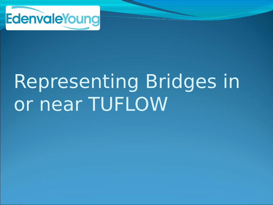
Blockage only at obstructed areas
Cells with Flow Constrictions only at bridge piers and abutments.
Energy loss and blockage applied locally.

2D bridge representation

2D bridge representation
Layered blockage methods
Apply blockage (and, optionally, energy losses) at some cells dependant on the water level
Uses TUFLOW layered flow constrictions
Suitable for most bridges.Difficult to apply to arches/variable soffit levels.
2D bridge representation
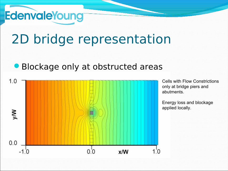
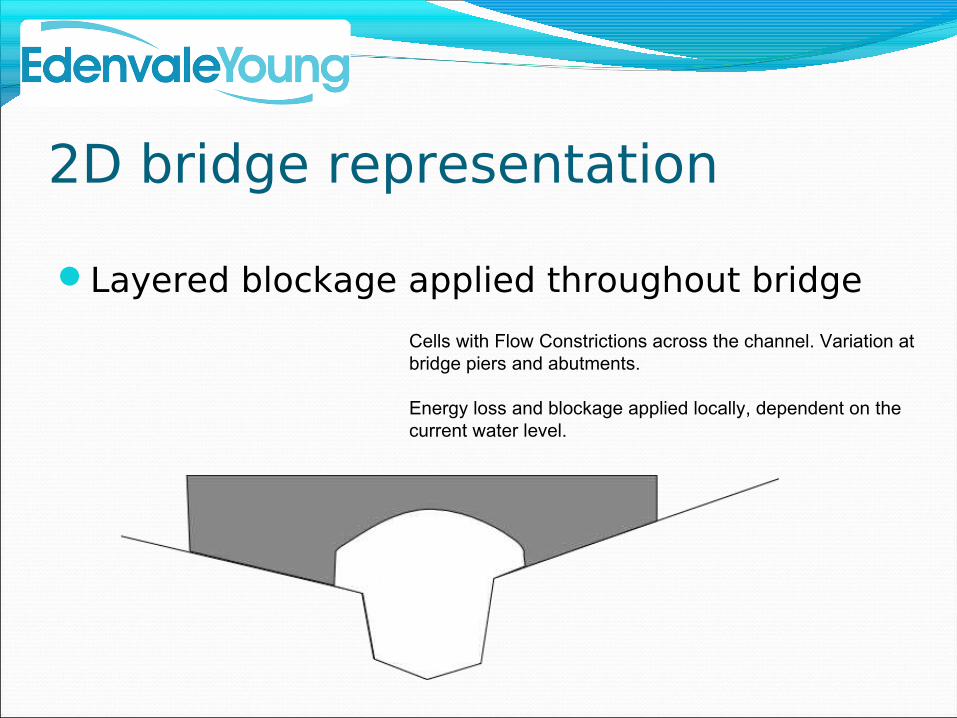
Layered blockage applied throughout bridge
Cells with Flow Constrictions across the channel. Variation at bridge piers and abutments.
Energy loss and blockage applied locally, dependent on the current water level.

1D bridge representation
ESTRY methodsType of linking: HX/SXType of ESTRY unit: Bridge/Culvert
Other external modelsType of linking: HX/SXChoices specific to external model

1D bridge representation
HX vs. SX linking for embedded bridge structuresSX: more stable, excessive spreading at the
outlet, zeroes momentumHX: less stable, requires smaller 2D timestep,
preserves some momentum
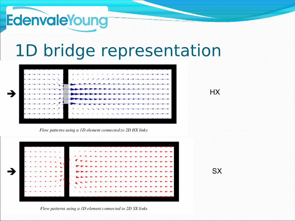
1D bridge representation
HX
SX

1D bridge representation
2D
HX
SX

1D bridge representation
ESTRY BridgesBased on US FHA 1973Using:
a constant form loss coefficient a form loss coefficient varying with water level
Estimation of the form loss coefficients can be tricky

1D bridge representation
1D bridge representation
ESTRY Bridges
FHWA only applicable to uniform, unidirectional flow.
Less accurate than surrounding 2D model

1D bridge representation
ESTRY CulvertsVarious culvert types: R, C, ILots of coefficients:
height contraction coefficient width contraction coefficient general entry loss coefficient exit loss coefficient
Little guidance on estimation when connecting to 2D

1D bridge representation
Other Models: ISISUSBPR Approach“Arch Bridge” ApproachOrifice UnitsCulverts of various shapes

What can go wrong?A comparison of ISIS approaches
Long Section: DON03_8843 - DON03_2824u - Maximum Stage; 5 - 40 h.
Node LabelDO
N03
_537
4
DO
N03
_516
7u
DO
N03
_507
8
DO
N03
_483
9u
DO
N03
_476
3u
DO
N03
_468
8u
DO
N03
_455
9u
DO
N03
_451
0u
DO
N03
_432
4u
DO
N03
_426
3u
DO
N03
_417
6u
DO
N03
_417
1
DO
N03
_414
7
Ele
vatio
n (m
AD
)
35.5
35
34.5
34
33.5
33
32.5
32
31.5
31
30.5
30
29.5
29
28.5
28
27.5
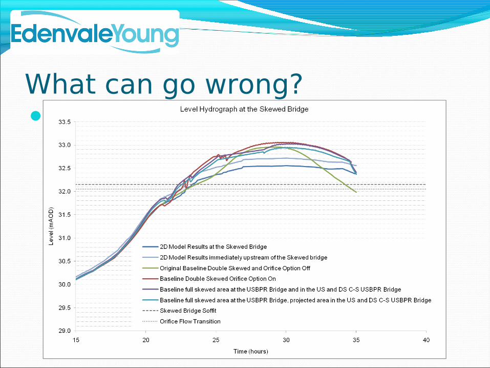
What can go wrong?A comparison of ISIS approaches

So what should be done?
When 1D/2D linking use 1D schematisation
When using pure 2D, use a schematisation appropriate to the grid size.
Read the manual. It gives useful information.

What to watch out for
When using pure 2D, TUFLOW can overestimate with default viscosity values.
Estimating coefficients for ESTRY is tricky.
ISIS uses really confusing naming for bridge parameters.

Doing it better
Of course, very accurate local modelling of bridges side-wall shear stress calculationsdirect force calculations
...require more than the shallow water equations...

Doing it better
This is a workshop!
That's enough chat.
Experiences on bridge modelling?Worries?How would you model...?What have you been talking about all this
time?