Embed Size (px)
Citation preview

Scalableand manageable storage systems
Khalil S.Amiri
December, 2000
CMU-CS-00-178
Department of Electrical and ComputerEngineering
CarnegieMellon University
Pittsburgh, PA 15213
Submitted in partial fulfillment of therequirements
for thedegreeof Doctor of Philosophy
Thesis Committee:
Garth A. Gibson,Chair
Gregory R. Ganger
M. Satyanarayanan
Daniel P. Siewiorek
JohnWilkes,HP Laboratories
This researchis sponsoredby DARPA/ITO, through DARPA OrderD306, andissuedby IndianHead Divisionunder
contract N00174-96-0002. Additional support wasprovided by generouscontributionsof the membercompaniesof the
Parallel DataConsortiumincluding 3COMCorporation, Compaq,DataGeneral,EMC,Hewlett-Packard,IBM, Intel, LSI
Logic, Novell, Inc., SeagateTechnology, StorageTek, QuantumCorporation and Wind River Systems. The views and
conclusions containedin this document are thoseof theauthor and should not beinterpretedasrepresenting theofficial
policiesor endorsements,eitherexpressedor implied,of any supporting organizationor theUSGovernment.


Keywords: storage, network-attached storage, storage management, distributed disk arrays, concurrency control, recovery, function partitioning.

Abstract
Emerging applications such as data warehousing, multimedia content distribution, electronic com-
merceandmedical andsatellite databaseshavesubstantial storagerequirementsthataregrowing at
3X to 5X per year. Such applications require scalable, highly-available and cost-effective storage
systems. Traditional storage systems rely on a central controller (file server, disk array controller)
to accessstorageandcopydatabetween storagedevicesandclientswhich limits their scalabilit y.
This dissertation describesan architecture, network-attached secure disks(NASD), that elimi-
natesthesingle controller bottleneck allowing throughput and bandwidth of anarray to scale with
increasing capacity up to the largest sizes desired in practice. NASD enablesdirect access from
client to sharedstoragedevices, allowing aggregatebandwidth to scalewith thenumberof nodes.
In ashared storagesystem,eachclientactsasitsown storage(RAID) controller, performing all
the functionsrequired to manageredundancy and access its data. As a result, multiple controllers
can beaccessingand managingsharedstoragedevicesconcurrently. Without properprovisions, this
concurrency cancorrupt redundancy codesand causehosts to readincorrect data. This dissertation
proposesatransactionalapproachtoensurecorrectnessin highly concurrentstoragedevicearrays. It
proposesdistributeddevice-basedprotocols thatexploit trendstowardsincreaseddeviceintelligence
to ensurecorrectnesswhilescaling well with systemsize.
Emerging network-attachedstoragearraysconsist of storagedeviceswith excesscycles in their
on-disk controllers, which can be used to execute filesystem function traditionally executed on
the host. Programmable storage devicesincrease the flexibility in partitioning filesystemfunction
betweenclients and storage devices. However, the heterogeneity in resource availability among
servers, clients and network links causes optimal function partitioning to change across sites and
with time. This dissertation proposesanautomatic approach which allows function partitioning to
be changed and optimizedat run-time by relying only on the black-box monitoring of functional
componentsand of resourceavailabilit y in thestoragesystem.
i

ii

This dissertation is dedicatedto my mother, Aicha, and to my late father, Sadok.
iii

iv

Acknowledgements
The writing of a dissertation can be a daunting and tasking experience. Fortunately, I was lucky
enough to have enjoyed thesupport of a large number of colleagues, family members, faculty and
friends that have made this processalmost enjoyable. First and foremost, however, I am grateful
to God for blessing me with a wonderful family and for giving me the opportunity andability to
completemy doctorate.
I would like to thank my advisor, Professor Garth Gibson, for his advice and encouragement
during my time at Carnegie Mellon. I am also grateful to the members of my thesis committee,
Gregory Ganger, Dan Siewiorek, SatyaandJohnWilkesfor agreeing to serveon thecommitteeand
for their valuable guidance and feedback. I am alsoindebted to John Wilkes for his mentoring and
encouragement during my internshipsatHP labs.
My officemates, neighbors, and collaborators on the NASD project, Fay Chang, Howard Go-
bioff, Erik Riedel and David Rochberg were great colleagues and wonderful friends. I am also
grateful to the membersof the RAIDFrameand NASD research groups and to the membersof the
entire Parallel DataLaboratory, who always proved readyto engagein challenging discussions. In
particular, I would like to thank Jeff Butler, Bill Courtright, Mark Holland, EugeneFeinberg, Paul
Mazaitis, David Nagle, Berend Ozceri, Hugo Patterson, TedWong, and Jim Zelenka. In addition,
I would like to thank LeAnn, Andy, Charles, Cheryl, Chris, Danner, John, Garth, Marc, Sean, and
Steve.
I am grateful to Joan Digney for her careful proofreading of this document, for her valuable
comments, and for her words of encouragement. I am also grateful to Patty for her friendship,
support, assistance,and for running such a largelaboratory sowell. I amequally grateful to Karen
for helping mewith so many tasksand simply for beingsuch awonderful person.
Duringmy timeatCarnegieMellon, I had several fruitful collaborationswith colleagueswithin
and outside the University. In particular, I would like to thank David Petrou, who worked with me
on ABACUS, for alwaysproving readyto engagein challengingdiscussionsor to start any design or
v

vi
implementation task wethought wasuseful. I would also liketo thank RichardGolding who worked
with meon thechallenging scalability and fault-toleranceproblemsin storageclusters. Richard was
always a source of good ideas,advice and encouragement, in addition to being greatcompany. I
amdeeply grateful to themembersof theParallel DataLab’s Industrial Consortium for helping me
understandthepractical issues surrounding our research proposals. In particular, I am grateful to
Dave Andersonand Chris Mallakapali of Seagate, to ElizabethBorowsky then of HP labs, to Don
Cameron of Intel, andto Satish Regeof Quantum.
I can not imagine my six years in graduateschool without the support of many friendsin the
United States and overseas. I would like to thank in particular Adel, Ferdaws, Gaddour, Karim,
Najed, Rita,Sandra,Sean, andSofiane.
Lastbut not least, I aminfinitely grateful to my mother, Aicha,andmy latefather, Sadok. They
providedme with unconditional love, advice, and support. My late father and his father before
him presented me with admirable role models of wisdom and perseverance. Despite our long-
distance relationship, my brothers and sisters, Charfeddine, Amel, Ghazi, Hajer, Nabeel, and Ines
overwhelmed me with morelove and support throughout my years in collegeand graduate school
thanwhat I could have ever deserved. Many thanks go to my uncles and aunts and their respective
families, for their unwaveringsupport.
Khalil Amiri
Pittsburgh, Pennsylvania
December, 2000

Contents
1 Intr oduction 1
1.1 Thestoragemanagement problem . . . . . . . . . . . . . . . . . . . . . . . . . . 2
1.1.1 Theideal storagesystem . . . . . . . . . . . . . . . . . . . . . . . . . . . 2
1.1.2 Theshortcomingsof current systems . . . . . . . . . . . . . . . . . . . . 3
1.2 Dissertation research . . . . . . . . . . . . . . . . . . . . . . . . . . . . . . . . . 4
1.3 Dissertation road map . . . . . . . . . . . . . . . . . . . . . . . . . . . . . . . . . 6
2 Background 9
2.1 Trendsin technology . . . . . . . . . . . . . . . . . . . . . . . . . . . . . . . . . 9
2.1.1 Magnetic disks . . . . . . . . . . . . . . . . . . . . . . . . . . . . . . . . 10
2.1.2 Memory . . . . . . . . . . . . . . . . . . . . . . . . . . . . . . . . . . . . 12
2.1.3 Processors . . . . . . . . . . . . . . . . . . . . . . . . . . . . . . . . . . 13
2.1.4 Interconnects . . . . . . . . . . . . . . . . . . . . . . . . . . . . . . . . . 14
2.2 Applicationdemandson storagesystems. . . . . . . . . . . . . . . . . . . . . . . 19
2.2.1 Flexiblecapacity . . . . . . . . . . . . . . . . . . . . . . . . . . . . . . . 19
2.2.2 High availability . . . . . . . . . . . . . . . . . . . . . . . . . . . . . . . 20
2.2.3 High bandwidth . . . . . . . . . . . . . . . . . . . . . . . . . . . . . . . . 21
2.3 Redundant diskarrays . . . . . . . . . . . . . . . . . . . . . . . . . . . . . . . . . 23
2.3.1 RAID level 0 . . . . . . . . . . . . . . . . . . . . . . . . . . . . . . . . . 24
2.3.2 RAID level 1 . . . . . . . . . . . . . . . . . . . . . . . . . . . . . . . . . 24
2.3.3 RAID level 5 . . . . . . . . . . . . . . . . . . . . . . . . . . . . . . . . . 24
2.4 Transactions . . . . . . . . . . . . . . . . . . . . . . . . . . . . . . . . . . . . . . 26
2.4.1 Transactions . . . . . . . . . . . . . . . . . . . . . . . . . . . . . . . . . 27
2.4.2 Serializabili ty . . . . . . . . . . . . . . . . . . . . . . . . . . . . . . . . . 28
2.4.3 Serializabili ty protocols . . . . . . . . . . . . . . . . . . . . . . . . . . . 30
2.4.4 Recovery protocols . . . . . . . . . . . . . . . . . . . . . . . . . . . . . . 37
vii

viii CONTENTS
2.5 Summary . . . . . . . . . . . . . . . . . . . . . . . . . . . . . . . . . . . . . . . 38
3 Network-at tached storagedevices 41
3.1 Trendsenablingnetwork-attachedstorage . . . . . . . . . . . . . . . . . . . . . . 42
3.1.1 Cost-ineffectivestoragesystems . . . . . . . . . . . . . . . . . . . . . . . 42
3.1.2 I/O-bound large-object applications . . . . . . . . . . . . . . . . . . . . . 44
3.1.3 New driveattachment technology . . . . . . . . . . . . . . . . . . . . . . 44
3.1.4 Convergenceof peripheral and interprocessor networks . . . . . . . . . . . 44
3.1.5 Excessof on-drive transistors . . . . . . . . . . . . . . . . . . . . . . . . 45
3.2 Two network-attachedstoragearchitectures . . . . . . . . . . . . . . . . . . . . . 45
3.2.1 Network SCSI . . . . . . . . . . . . . . . . . . . . . . . . . . . . . . . . 45
3.2.2 Network-Attached SecureDisks (NASD) . . . . . . . . . . . . . . . . . . 47
3.3 TheNASD architecture . . . . . . . . . . . . . . . . . . . . . . . . . . . . . . . . 48
3.3.1 Directtransfer . . . . . . . . . . . . . . . . . . . . . . . . . . . . . . . . 49
3.3.2 Asynchronousoversight . . . . . . . . . . . . . . . . . . . . . . . . . . . 50
3.3.3 Object-based interface . . . . . . . . . . . . . . . . . . . . . . . . . . . . 51
3.4 TheCheopsstorageservice . . . . . . . . . . . . . . . . . . . . . . . . . . . . . . 54
3.4.1 Cheopsdesign overview . . . . . . . . . . . . . . . . . . . . . . . . . . . 54
3.4.2 Layout protocols . . . . . . . . . . . . . . . . . . . . . . . . . . . . . . . 57
3.4.3 Storageaccessprotocols . . . . . . . . . . . . . . . . . . . . . . . . . . . 58
3.4.4 Implementation . . . . . . . . . . . . . . . . . . . . . . . . . . . . . . . . 58
3.5 Scalable bandwidth onCheops-NASD . . . . . . . . . . . . . . . . . . . . . . . . 59
3.5.1 Evaluation environment . . . . . . . . . . . . . . . . . . . . . . . . . . . 60
3.5.2 Raw bandwidth scaling . . . . . . . . . . . . . . . . . . . . . . . . . . . . 61
3.6 Otherscalablestoragearchitectures . . . . . . . . . . . . . . . . . . . . . . . . . 63
3.6.1 Decouplingcontrol from data transfer . . . . . . . . . . . . . . . . . . . . 63
3.6.2 Network-striping . . . . . . . . . . . . . . . . . . . . . . . . . . . . . . . 64
3.6.3 Parallel andclusteredstoragesystems . . . . . . . . . . . . . . . . . . . . 66
3.7 Summary . . . . . . . . . . . . . . . . . . . . . . . . . . . . . . . . . . . . . . . 68
4 Sharedstoragearrays 71
4.1 Ensuring correctnessin sharedarrays . . . . . . . . . . . . . . . . . . . . . . . . . 72
4.1.1 Concurrency anomalies in sharedarrays . . . . . . . . . . . . . . . . . . . 73
4.1.2 Failureanomalies in sharedarrays . . . . . . . . . . . . . . . . . . . . . . 74
CONTENTS ix
4.2 Systemdescription . . . . . . . . . . . . . . . . . . . . . . . . . . . . . . . . . . 75
4.2.1 Storagecontrollers . . . . . . . . . . . . . . . . . . . . . . . . . . . . . . 76
4.2.2 Storagemanagers . . . . . . . . . . . . . . . . . . . . . . . . . . . . . . . 77
4.3 Storageaccessand management using BSTs . . . . . . . . . . . . . . . . . . . . . 78
4.3.1 Fault-freemode . . . . . . . . . . . . . . . . . . . . . . . . . . . . . . . . 79
4.3.2 Degraded mode . . . . . . . . . . . . . . . . . . . . . . . . . . . . . . . . 80
4.3.3 Migrating mode. . . . . . . . . . . . . . . . . . . . . . . . . . . . . . . . 80
4.3.4 Reconstructing mode . . . . . . . . . . . . . . . . . . . . . . . . . . . . . 83
4.3.5 Thestructureof BSTs . . . . . . . . . . . . . . . . . . . . . . . . . . . . 83
4.4 BST properties . . . . . . . . . . . . . . . . . . . . . . . . . . . . . . . . . . . . 85
4.4.1 BST Consistency . . . . . . . . . . . . . . . . . . . . . . . . . . . . . . . 85
4.4.2 BST Durabili ty . . . . . . . . . . . . . . . . . . . . . . . . . . . . . . . . 85
4.4.3 No atomicity . . . . . . . . . . . . . . . . . . . . . . . . . . . . . . . . . 86
4.4.4 BST Isolation . . . . . . . . . . . . . . . . . . . . . . . . . . . . . . . . . 86
4.5 Serializabili ty protocols for BSTs . . . . . . . . . . . . . . . . . . . . . . . . . . 87
4.5.1 Evaluation environment . . . . . . . . . . . . . . . . . . . . . . . . . . . 87
4.5.2 Centralizedlocking . . . . . . . . . . . . . . . . . . . . . . . . . . . . . . 88
4.5.3 Parallel lockservers . . . . . . . . . . . . . . . . . . . . . . . . . . . . . 92
4.5.4 Device-servedlocking . . . . . . . . . . . . . . . . . . . . . . . . . . . . 92
4.5.5 Timestampordering . . . . . . . . . . . . . . . . . . . . . . . . . . . . . 95
4.5.6 Sensitivity analysis . . . . . . . . . . . . . . . . . . . . . . . . . . . . . . 100
4.6 Caching storagecontrollers . . . . . . . . . . . . . . . . . . . . . . . . . . . . . . 104
4.6.1 Device-servedleases . . . . . . . . . . . . . . . . . . . . . . . . . . . . . 106
4.6.2 Timestampordering with validation . . . . . . . . . . . . . . . . . . . . . 107
4.6.3 Latency andscaling . . . . . . . . . . . . . . . . . . . . . . . . . . . . . . 110
4.6.4 Network messaging . . . . . . . . . . . . . . . . . . . . . . . . . . . . . . 112
4.6.5 Read/writecompositionand locality . . . . . . . . . . . . . . . . . . . . . 114
4.6.6 Sensitivity to leaseduration . . . . . . . . . . . . . . . . . . . . . . . . . 116
4.6.7 Timestamplog truncation . . . . . . . . . . . . . . . . . . . . . . . . . . 118
4.6.8 Implementation complexity . . . . . . . . . . . . . . . . . . . . . . . . . 119
4.7 Recovery for BSTs . . . . . . . . . . . . . . . . . . . . . . . . . . . . . . . . . . 120
4.7.1 Failuremodel andassumptions . . . . . . . . . . . . . . . . . . . . . . . . 120
4.7.2 An overview of recovery for BSTs . . . . . . . . . . . . . . . . . . . . . . 124
x CONTENTS
4.7.3 Recovery in fault-freeandmigrating modes . . . . . . . . . . . . . . . . . 127
4.7.4 Recovery in degraded and reconstructing modes . . . . . . . . . . . . . . 131
4.7.5 Storagemanager actions in therecovering mode . . . . . . . . . . . . . . 132
4.7.6 Therecoveryprotocols . . . . . . . . . . . . . . . . . . . . . . . . . . . . 135
4.8 Discussion . . . . . . . . . . . . . . . . . . . . . . . . . . . . . . . . . . . . . . . 139
4.8.1 Relaxing readsemantics . . . . . . . . . . . . . . . . . . . . . . . . . . . 139
4.8.2 Extension to other RAID levels . . . . . . . . . . . . . . . . . . . . . . . 140
4.8.3 Recovery . . . . . . . . . . . . . . . . . . . . . . . . . . . . . . . . . . . 140
4.9 Summary . . . . . . . . . . . . . . . . . . . . . . . . . . . . . . . . . . . . . . . 141
5 Adaptiveand automatic function placement 143
5.1 Emerging storagesystems:ActiveandHeterogeneous . . . . . . . . . . . . . . . . 144
5.1.1 Programmability: Activeclientsanddevices . . . . . . . . . . . . . . . . 144
5.1.2 Heterogeneity . . . . . . . . . . . . . . . . . . . . . . . . . . . . . . . . . 145
5.1.3 Assumptionsand system description . . . . . . . . . . . . . . . . . . . . . 146
5.2 Function placement in traditional filesystems . . . . . . . . . . . . . . . . . . . . 148
5.2.1 Parallel filesystems . . . . . . . . . . . . . . . . . . . . . . . . . . . . . . 148
5.2.2 Local areanetwork filesystems. . . . . . . . . . . . . . . . . . . . . . . . 150
5.2.3 Wideareanetwork filesystems . . . . . . . . . . . . . . . . . . . . . . . . 151
5.2.4 Storageareanetwork filesystems . . . . . . . . . . . . . . . . . . . . . . . 151
5.2.5 Activedisksystems. . . . . . . . . . . . . . . . . . . . . . . . . . . . . . 152
5.2.6 A motivating example . . . . . . . . . . . . . . . . . . . . . . . . . . . . 153
5.3 Overview of theABACUS system . . . . . . . . . . . . . . . . . . . . . . . . . . . 154
5.3.1 Prototypedesign goals . . . . . . . . . . . . . . . . . . . . . . . . . . . . 155
5.3.2 Overview of theprogramming model . . . . . . . . . . . . . . . . . . . . 155
5.3.3 Objectmodel . . . . . . . . . . . . . . . . . . . . . . . . . . . . . . . . . 159
5.3.4 Run-time system . . . . . . . . . . . . . . . . . . . . . . . . . . . . . . . 161
5.4 Automatic placement . . . . . . . . . . . . . . . . . . . . . . . . . . . . . . . . . 165
5.4.1 Goals . . . . . . . . . . . . . . . . . . . . . . . . . . . . . . . . . . . . . 167
5.4.2 Overview of theperformancemodel . . . . . . . . . . . . . . . . . . . . . 168
5.4.3 Singlestack . . . . . . . . . . . . . . . . . . . . . . . . . . . . . . . . . . 169
5.4.4 Concurrent stacks . . . . . . . . . . . . . . . . . . . . . . . . . . . . . . . 171
5.4.5 Cost-benefit model . . . . . . . . . . . . . . . . . . . . . . . . . . . . . . 172
5.4.6 Monitoringandmeasurement . . . . . . . . . . . . . . . . . . . . . . . . 175

CONTENTS xi
5.5 A mobile filesystem . . . . . . . . . . . . . . . . . . . . . . . . . . . . . . . . . . 179
5.5.1 Overview . . . . . . . . . . . . . . . . . . . . . . . . . . . . . . . . . . . 180
5.5.2 NASD object service . . . . . . . . . . . . . . . . . . . . . . . . . . . . . 183
5.6 Evaluation of filesystemadaptation . . . . . . . . . . . . . . . . . . . . . . . . . . 183
5.6.1 Evaluation environment . . . . . . . . . . . . . . . . . . . . . . . . . . . 184
5.6.2 File caching . . . . . . . . . . . . . . . . . . . . . . . . . . . . . . . . . . 184
5.6.3 Striping and RAID . . . . . . . . . . . . . . . . . . . . . . . . . . . . . . 188
5.6.4 Directory management . . . . . . . . . . . . . . . . . . . . . . . . . . . . 191
5.7 Supportinguserapplications . . . . . . . . . . . . . . . . . . . . . . . . . . . . . 197
5.7.1 Example application scenarios . . . . . . . . . . . . . . . . . . . . . . . . 198
5.7.2 Casestudy: Filtering . . . . . . . . . . . . . . . . . . . . . . . . . . . . . 199
5.8 Dynamicevaluationof ABACUS . . . . . . . . . . . . . . . . . . . . . . . . . . . 201
5.8.1 Adapting to competition over resources . . . . . . . . . . . . . . . . . . . 202
5.8.2 Adapting to changesin theworkload . . . . . . . . . . . . . . . . . . . . . 202
5.8.3 Systemoverhead . . . . . . . . . . . . . . . . . . . . . . . . . . . . . . . 203
5.8.4 Threshold benefit and history size . . . . . . . . . . . . . . . . . . . . . . 205
5.9 Discussion . . . . . . . . . . . . . . . . . . . . . . . . . . . . . . . . . . . . . . . 206
5.9.1 Programming model and run-timesystem . . . . . . . . . . . . . . . . . . 206
5.9.2 Security . . . . . . . . . . . . . . . . . . . . . . . . . . . . . . . . . . . . 207
5.10 Related work . . . . . . . . . . . . . . . . . . . . . . . . . . . . . . . . . . . . . 209
5.10.1 Processmigration . . . . . . . . . . . . . . . . . . . . . . . . . . . . . . . 209
5.10.2 Programming systemssupportingobject mobili ty . . . . . . . . . . . . . . 212
5.10.3 Mobileagent systems. . . . . . . . . . . . . . . . . . . . . . . . . . . . . 213
5.10.4 Remoteevaluation . . . . . . . . . . . . . . . . . . . . . . . . . . . . . . 214
5.10.5 Activedisks . . . . . . . . . . . . . . . . . . . . . . . . . . . . . . . . . . 215
5.10.6 Applicationobject partitioning . . . . . . . . . . . . . . . . . . . . . . . . 215
5.10.7 Databasesystems . . . . . . . . . . . . . . . . . . . . . . . . . . . . . . . 217
5.10.8 Parallel programming systems . . . . . . . . . . . . . . . . . . . . . . . . 217
5.11 Summary . . . . . . . . . . . . . . . . . . . . . . . . . . . . . . . . . . . . . . . 218
6 Conclusionsand futur e work 221
6.1 Dissertation summary . . . . . . . . . . . . . . . . . . . . . . . . . . . . . . . . . 221
6.1.1 Network-attachedstorage . . . . . . . . . . . . . . . . . . . . . . . . . . 221
6.1.2 Sharedstoragearrays . . . . . . . . . . . . . . . . . . . . . . . . . . . . . 222

xii CONTENTS
6.1.3 Dynamicandautomatic functionplacement . . . . . . . . . . . . . . . . . 224
6.2 Contributions . . . . . . . . . . . . . . . . . . . . . . . . . . . . . . . . . . . . . 225
6.2.1 Results . . . . . . . . . . . . . . . . . . . . . . . . . . . . . . . . . . . . 225
6.2.2 Artifacts. . . . . . . . . . . . . . . . . . . . . . . . . . . . . . . . . . . . 226
6.3 Futurework . . . . . . . . . . . . . . . . . . . . . . . . . . . . . . . . . . . . . . 226

List of Figures
2.1 Themechanismsin amagnetic disk . . . . . . . . . . . . . . . . . . . . . . . . . 10
2.2 Trendsin thecost of alternativestoragemedia . . . . . . . . . . . . . . . . . . . . 12
2.3 Heterogeneity in campusnetworks . . . . . . . . . . . . . . . . . . . . . . . . . . 18
2.4 Annual storagecapacity growth by application . . . . . . . . . . . . . . . . . . . . 19
2.5 RAID level 5 layout . . . . . . . . . . . . . . . . . . . . . . . . . . . . . . . . . . 24
2.6 RAID level 5 operations in fault-freemode . . . . . . . . . . . . . . . . . . . . . 25
2.7 RAID level 5 operations in degraded mode. . . . . . . . . . . . . . . . . . . . . . 26
2.8 Timestampordering scenario in adatabasesystem . . . . . . . . . . . . . . . . . . 36
3.1 Server-attached-diskarchitecture . . . . . . . . . . . . . . . . . . . . . . . . . . . 43
3.2 NetSCSI storagearchitecture . . . . . . . . . . . . . . . . . . . . . . . . . . . . . 46
3.3 Network-attachedsecuredisk architecture . . . . . . . . . . . . . . . . . . . . . . 49
3.4 NASD objectattributes . . . . . . . . . . . . . . . . . . . . . . . . . . . . . . . . 53
3.5 Cheopsarchitecture . . . . . . . . . . . . . . . . . . . . . . . . . . . . . . . . . . 55
3.6 Striping over NASDs . . . . . . . . . . . . . . . . . . . . . . . . . . . . . . . . . 56
3.7 A NASD-optimizedparallel filesystem . . . . . . . . . . . . . . . . . . . . . . . . 59
3.8 Scalable data-miningon Cheops/NASD . . . . . . . . . . . . . . . . . . . . . . . 62
4.1 Scalable storagearrays . . . . . . . . . . . . . . . . . . . . . . . . . . . . . . . . 72
4.2 An exampleconcurrency anomaly in a sharedstoragearray . . . . . . . . . . . . . 74
4.3 Inconsistenciesdueto untimely failuresin ashared array . . . . . . . . . . . . . . 75
4.4 Overview of asharedstoragearray . . . . . . . . . . . . . . . . . . . . . . . . . . 76
4.5 Storage transactionsusedin fault-freemode . . . . . . . . . . . . . . . . . . . . . 81
4.6 Storage transactionsusedin degradedmode . . . . . . . . . . . . . . . . . . . . . 81
4.7 Storage transactionsusedin migrating mode. . . . . . . . . . . . . . . . . . . . . 83
4.8 Storage transactionsusedin reconstructingmode . . . . . . . . . . . . . . . . . . 84
xiii
xiv LIST OF FIGURES
4.9 Storage-level operations . . . . . . . . . . . . . . . . . . . . . . . . . . . . . . . 84
4.10 Scaling of centralized lockingprotocols . . . . . . . . . . . . . . . . . . . . . . . 89
4.11 Scaling of centralized lockingunder increasedcontention . . . . . . . . . . . . . . 90
4.12 Effect of contention on callback locking . . . . . . . . . . . . . . . . . . . . . . . 91
4.13 Device-servedlocking operation graph . . . . . . . . . . . . . . . . . . . . . . . . 93
4.14 Messaging overheadof thevariousprotocols . . . . . . . . . . . . . . . . . . . . . 94
4.15 Scaling of centralized and device-served locking . . . . . . . . . . . . . . . . . . . 95
4.16 Scaling of centralized and device-served lockingunder increased contention . . . . 96
4.17 Timestampordering operation graph . . . . . . . . . . . . . . . . . . . . . . . . . 96
4.18 Scaling of centralized and device-based protocols . . . . . . . . . . . . . . . . . . 97
4.19 Effect of read/writeworkload mix on messagingoverhead . . . . . . . . . . . . . 101
4.20 Effect of network variability on the fractionof operationsdelayed . . . . . . . . . 102
4.21 Effect of network variability on host latency . . . . . . . . . . . . . . . . . . . . . 102
4.22 Effect of fasterdisksonprotocol scalability . . . . . . . . . . . . . . . . . . . . . 103
4.23 Overview of a caching shared storagearray . . . . . . . . . . . . . . . . . . . . . 106
4.24 Device-servedleasing operation graph . . . . . . . . . . . . . . . . . . . . . . . . 108
4.25 Timestampordering with validationoperationgraph . . . . . . . . . . . . . . . . . 109
4.26 Scaling of caching storagecontrollers . . . . . . . . . . . . . . . . . . . . . . . . 111
4.27 Messaging overheadof thecaching protocols . . . . . . . . . . . . . . . . . . . . 113
4.28 Effect of read/writeworkload mix on host latency . . . . . . . . . . . . . . . . . . 115
4.29 Effect of read/writeworkload mix on messagingoverhead . . . . . . . . . . . . . 115
4.30 Effect of leaseduration on thefraction of operationsdelayed . . . . . . . . . . . . 116
4.31 Effect of leaseduration onmessaging overhead . . . . . . . . . . . . . . . . . . . 117
4.32 Effect of leaseduration onhost latency . . . . . . . . . . . . . . . . . . . . . . . . 117
4.33 Effect of timestamplog sizeon host latency . . . . . . . . . . . . . . . . . . . . . 119
4.34 Accessandlayout protocols in asharedstoragearray . . . . . . . . . . . . . . . . 122
4.35 Devicesstatesduring theprocessing of aBST . . . . . . . . . . . . . . . . . . . . 123
4.36 Modesof avirtual object . . . . . . . . . . . . . . . . . . . . . . . . . . . . . . . 125
4.37 Controller statesduring theexecution of a BST . . . . . . . . . . . . . . . . . . . 129
5.1 Function placement in parallel filesystems . . . . . . . . . . . . . . . . . . . . . . 149
5.2 Function placement in network filesystems. . . . . . . . . . . . . . . . . . . . . . 150
5.3 Function placement in activedisk systems . . . . . . . . . . . . . . . . . . . . . . 152

LIST OF FIGURES xv
5.4 A filesystem asanABACUS application . . . . . . . . . . . . . . . . . . . . . . . 157
5.5 A user-level program asanABACUS application . . . . . . . . . . . . . . . . . . . 158
5.6 ABACUS prototypearchitecture . . . . . . . . . . . . . . . . . . . . . . . . . . . . 162
5.7 Mobileobject interface . . . . . . . . . . . . . . . . . . . . . . . . . . . . . . . . 165
5.8 Break-down of applicationexecution time . . . . . . . . . . . . . . . . . . . . . . 169
5.9 A prototypeobject-basedfilesystem . . . . . . . . . . . . . . . . . . . . . . . . . 181
5.10 Evaluation environment . . . . . . . . . . . . . . . . . . . . . . . . . . . . . . . . 185
5.11 Cacheplacement scenarios . . . . . . . . . . . . . . . . . . . . . . . . . . . . . . 186
5.12 Cachebenchmark results . . . . . . . . . . . . . . . . . . . . . . . . . . . . . . . 187
5.13 Example per-client placement of filesystemsobjects . . . . . . . . . . . . . . . . . 188
5.14 RAID placement results . . . . . . . . . . . . . . . . . . . . . . . . . . . . . . . . 190
5.15 Directory management in ABACUSFS . . . . . . . . . . . . . . . . . . . . . . . . 193
5.16 Directory placement results . . . . . . . . . . . . . . . . . . . . . . . . . . . . . . 196
5.17 Timelineof functionmigration for two clientscontendingon ashared directory . . 197
5.18 Filterperformanceunder ABACUS . . . . . . . . . . . . . . . . . . . . . . . . . . 199
5.19 Filterplacementresults . . . . . . . . . . . . . . . . . . . . . . . . . . . . . . . . 200
5.20 Competingfilter benchmark . . . . . . . . . . . . . . . . . . . . . . . . . . . . . 201
5.21 Timelineof themultiphasiccachebenchmark . . . . . . . . . . . . . . . . . . . . 204
5.22 Cost and benefitestimatesversus time . . . . . . . . . . . . . . . . . . . . . . . . 205
6.1 Scalable storagearrays . . . . . . . . . . . . . . . . . . . . . . . . . . . . . . . . 223
6.2 Managing heterogeneity . . . . . . . . . . . . . . . . . . . . . . . . . . . . . . . 224

xvi LIST OF FIGURES

List of Tables
2.1 Trendsin theperformanceof magnetic disks . . . . . . . . . . . . . . . . . . . . . 11
2.2 Bandwidth of alternativeEthernet technologies . . . . . . . . . . . . . . . . . . . 15
2.3 Cost trends for EthernetHubs . . . . . . . . . . . . . . . . . . . . . . . . . . . . . 16
2.4 Cost trends for EthernetSwitches. . . . . . . . . . . . . . . . . . . . . . . . . . . 16
2.5 Cost of down-timeby application . . . . . . . . . . . . . . . . . . . . . . . . . . . 20
3.1 TheNASD interface . . . . . . . . . . . . . . . . . . . . . . . . . . . . . . . . . 52
4.1 BSTsusedin differentmodes. . . . . . . . . . . . . . . . . . . . . . . . . . . . . 80
4.2 Baselinesimulation parameters . . . . . . . . . . . . . . . . . . . . . . . . . . . . 88
4.3 Baselineperformanceresults . . . . . . . . . . . . . . . . . . . . . . . . . . . . . 99
4.4 Implementation complexity of thecaching protocols . . . . . . . . . . . . . . . . 120
4.5 Summaryof recovery actionstakenuponfailuresand outages. . . . . . . . . . . . 133
5.1 Functionplacement in distributed storagesystems . . . . . . . . . . . . . . . . . . 154
5.2 Copyplacement results . . . . . . . . . . . . . . . . . . . . . . . . . . . . . . . . 191
5.3 Directory retriesand function placement . . . . . . . . . . . . . . . . . . . . . . . 196
5.4 Cacheplacement for applicationswith contrasting phases. . . . . . . . . . . . . . 203
xvii

Chapter 1
Intr oduction
Datasetsstoredon-linearegrowingatphenomenal rates,oftendoublingevery year [Emanuel, 1997],
and reaching several terabytes at typical e-commercecompanies [Lycos, 1999]. Examplesinclude
repositories of satellite and medical images, data warehouses of business information, multimedia
entertainment content, on-line catalogs, and attachment-rich email archives. The explosive growth
of electronic commerce [News,1998] is generating hugearchives of businesstransaction records
and customer shopping histories every week [EnStor, 1997]. It is also reported that NASA’s new
earth observing satellit e wil l generate data sets up to three timesaslargeasthe size of the Library
of Congresseveryyear.
Giventheserapid growth rates, organizations face theneedto incrementally scale their storage
systems asdemand for their servicesgrows and their datasetsexpand. For many companies, es-
timating the growth rateis not an easy task [Lycos, 1999]. This makesthe need to incrementally
scalesystemsin response to unpredictable demand a pressing concernin practice. Traditional stor-
agesystemsrely on file serversto copydatabetweenclientsand storagedevices. Fileservers,unlike
network switches, arenot efficient in moving data between clients andstorage nodesbecause they
interposesynchronouscontrol functions in themiddleof thedatapath. Asaresult, file servershave
emerged asa severe scalabili ty bottleneck in storagesystems. Consequently, to deliver acceptable
bandwidth to clients, file servers have to be custom built or behigh-end machinesimposing a high
cost overhead. Expanding storage beyond a single file server’s capacity is also costly because it
requiresacquiring anew serverand becauseit requiressystemadministrators to explicitly replicate
filesandbalanceload and capacity acrosstheservers.
Theimportanceof storagesystem performanceandavailabilit y in practice leadsto theemploy-
mentof a plethora of manual and ad-hoc techniques to ensure high-availability and balanced load.
Not surprisingly, thecost of storagemanagement continuesto bethe leading component in thecost
1
2 CHAPTER 1. INTRODUCTION
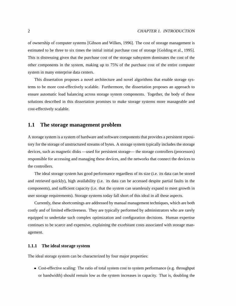
of ownership of computer systems [GibsonandWilkes, 1996]. Thecost of storage management is
estimated to be threeto six timesthe initial initial purchasecost of storage [Goldinget al., 1995].
This is distressing given that thepurchasecost of thestorage subsystem dominates the cost of the
other components in the system, making up to 75% of the purchase cost of the entire computer
system in many enterprisedatacenters.
This dissertation proposesa novel architecture and novel algorithms that enable storage sys-
tems to be more cost-effectively scalable. Furthermore, the dissertation proposes an approach to
ensure automatic load balancing acrossstorage system components. Together, the body of these
solutions described in this dissertation promises to make storage systemsmore manageable and
cost-effectively scalable.
1.1 The storagemanagementproblem
A storagesystem isasystemof hardwareandsoftwarecomponentsthatprovidesapersistent reposi-
tory for thestorageof unstructuredstreamsof bytes.A storagesystem typically includesthestorage
devices,such asmagnetic disks—usedfor persistent storage— thestoragecontrollers (processors)
responsible for accessing and managing thesedevices,andthenetworks that connectthedevicesto
thecontrollers.
Theideal storagesystemhasgood performance regardlessof its size (i.e. its data can bestored
and retrieved quickly), high availability (i.e. its data canbe accessed despite partial faults in the
components), and sufficient capacity (i.e. thatthesystem canseamlessly expand to meet growth in
userstoragerequirements). Storagesystems today fall short of this ideal in all theseaspects.
Currently, theseshortcomingsareaddressed by manualmanagement techniques,whichareboth
costly and of limited effectiveness. They aretypically performedby administrators who are rarely
equipped to undertake such complex optimization andconfiguration decisions. Humanexpertise
continuesto bescarceand expensive, explaining theexorbitant costsassociatedwith storage man-
agement.
1.1.1 The ideal storagesystem
Theideal storagesystem can becharacterized by four major properties:
� Cost-effective scaling: The ratio of total systemcost to system performance(e.g. throughput
or bandwidth) should remain low as the system increasesin capacity. That is, doubling the

1.1. THE STORAGE MANAGEMENT PROBLEM 3
number of components (cost) of thesystem should double itsperformance.This requires that
systemresourcesbeeffectively util ized. Theseresourcesareoften unevenly distributed across
thedifferentnodesin thestoragesystem.
� Availability: The storage system should continue to servedata even if a limited number of
components fail.
� Flexiblecapacity througheasyand incremental growth: To meetexpansion needs,increasing
thesizeshould beasimple and almostentirely automatic task.
� Security: The storagesystem must enforce data privacy, integrity andallow users to define
expressiveaccesscontrol policies.
1.1.2 Theshortcomingsof curr ent systems
The storage systems that are most widely used in medium and high-end serverstoday areredun-
dant disk arrays, multi -disk systemsthat usedisk striping and parity codes to balance loadacross
disks, provide increased bandwidthon large transfers, andensuredataavailabili ty despitedisk fail-
ures[Patterson etal., 1988]. Toscalethecapacity of astoragesystembeyond themaximumcapacity
or performance of a single disk array, multiple disk arraysareused. Load and capacity are often
balanced manually by moving volumesbetween thearrays. Expanding the systemby a few disks
sometimesrequiresthepurchaseof anew array, amajor stepincrease in cost. Thisoccurswhen the
capacity of thearrayhasreached itsmaximum or whentheload onthecontroller becomestoohigh.
Management operations suchasstorage migration and reconstruction areeithercarried off-lineor
performedon-line by thecentral array controller, restricting thesystem’sscalability.
A storagesystemincludesclients,array controllersand (potentially programmable)storagede-
vices. Theresourcesavailable at thesenodesvary acrosssystemsandwith time. Balancing the load
across the system components often requires rewriting filesystemsand applications to adjust the
partitioning of function between nodes(clients and servers) to takeadvantage of changesin tech-
nology and applications.Filesystemshavetraditionally dictated thatall user applicationsexecuteon
theclient, thereby opting for a “datashipping” approach,wherefile blocksareshippedto theclient
and processed there. Recently, however, with the availability of excess cycles in storage devices
and servers, research hasdemonstrated dramatic benefitsfrom exploiting thesecycles to perform
filtering, aggregation andother application-specific processing on datastreams. Function shipping

4 CHAPTER 1. INTRODUCTION
reducesthe amount of data that has to be shippedback to the client andsubstantially improves
performance.
Function shipping is not always the ideal choice,however. Devicesand servers can be easily
overloaded sincetheir resourcesare limited compared to the aggregate client resources. Whether
dataor functionshipping ismoreoptimal dependson current loadconditions, theworkload mix and
application characteristics.Currently, optimal function partitioning of function is theresponsibilit y
of theprogrammerandsystemadministrator. Thisaddsto thecost of storagemanagement.
Tobattleincreasingstoragesystemmanagementcosts, storagesystemsshouldscalecost-effectively
and balanceloadautomatically without manual intervention.
This dissertation identifies andaddressesthreekey technical challenges to making storage sys-
temsmorecost-effectively scalableand manageable.
1.2 Dissertation research
The research in this dissertation consists of three relatively independent parts. The first part in-
troduces a storage system architecture, network attachedsecure disks (NASD), that enables cost-
effective bandwidth scaling andincremental capacity growth. NASD modifies the storagedevice
interfaceto allow it to transfer datadirectly to end clientswithout copyingdatathroughacentralized
storage controller or file server. The basic ideais to have clients cache the mapping from a high-
level file name to anobject on a NASD device. The client then usesthis cachedmapping to map a
file accessonto aNASD deviceaccess. Data is transferredbetweentheclient and theNASDdevice
without a copy through the server. Using a scalable switchednetwork to connect the clients and
thedevices,thestoragesystem canbeexpandedandits performancescaled by attaching additional
NASD devicesand clients to thenetwork. Thisarchitectureis described in Chapter3.
TheNASD architectureallowsclientsdirect accessto NASD devices.By striping acrossNASD
devices, clients can achieve high bandwidths on large transfers. The function that implements
this striping acrossmultiple storagedevices,and which generally implements theRAID protocols
(whichmaintain redundancy and managetheblock layout maps),must thereforebeexecutedat the
client so that data travels from source to sink directly without being copied through a store-and-
forwardnode. A NASD systemtherefore containsmultiple controllers (at multiple clients) which
can besimultaneously accessingstorageat thesametime. Thesecontrollersmustbecoordinated so
that racesdonot corrupt redundancy codesor causeclients to readincorrect data.
The second part of the dissertation, namely Chapter 4, presents an approach basedon light-

1.2. DISSERTATION RESEARCH 5
weight transactions which allows storage controllers to be active concurrently. Specifically, mul-
tiple controllers canbe accessing shareddevices while managementtasks (such asdata migration
or reconstruction) are ongoing at other controllers. The protocols distribute the work of ensuring
concurrency control andrecovery to theendpoints. As a result, they do not suffer from thesingle
controllerbottleneck of traditional arrays. Distributedprotocolsunfortunately suffer from increased
implementation complexity and involve highermessaging overhead. Both arevery undesirable in
storage systemsbecause they increasethe chance of implementation bugs and limit performance.
This part shows how complexity canbemanaged by breaking down the probleminto subproblems
and solving eachsubproblem separately. Theproposedsolutionparallelspreviouswork on database
transaction theory. It relieson simple two-phasedoperations, called storagetransactions,as abasic
building block of the solution. This part also proposesan optimistic protocol basedon timestamps
derived from loosely synchronizedclocks that exhibits good scalability, low latency and limited
device-side state and complexity. This protocol is shown to work well for random access and con-
tended workloads typical of clustered storage systems. Furthermore, it is shown to have robust
performanceacrossworkloadsandsystemparameters.
The third part of the dissertation tackles theproblemof function partitioning in thecontext of
data-intensive applicationsexecuting over distributedstoragesystems.Rapidly changing technolo-
gies cause a single storage system to be composedof multiple storage devicesand clients with
disparate levels of CPU and memory resources. The interconnection network is rarely a simple
crossbar, and is usually quite heterogeneous. Thebandwidth available betweenpairs of nodes de-
pends on the physical link topology betweenthe two nodes and also on the dynamicload on the
entire network. In addition to hardware heterogeneity, applications also have characteristics that
vary with input argumentsand with time.
The research described in this part demonstrates that theperformance of storagemanagement
and data-intensive applications canbe improvedsignificantly by adaptively partitioning their func-
tionsbetween storageserversand clients. Chapter5 describesaprogramming systemwhichallows
applications to be composedof components that canbe adaptively bound to the client or server at
run-time. It proposesan approach whereinapplication componentsareobservedasblack-boxesthat
communicatewith eachother. An on-lineperformancemodel is usedto dynamically decideto place
and re-placecomponents betweencluster nodes. It also quantifies the benefitsof adaptive function
partitioning throughseveral microbenchmarks.
Thethesis of thisdissertationcanbesummarized asfollows:

6 CHAPTER 1. INTRODUCTION
1. Parallel hosts attached to an array of shared storage devices via a switched network can
achievescalablebandwidth anda sharedvirtual storageabstraction.
2. Using smart devicesfor distributed concurrency control in storage clusters achievesgood
scalabilit y while requiri ng limiteddevice-sidestate.
3. Proper function placement is crucial to the performance of storage managementand data-
intensiveapplicationsand can be decided basedon the black-box monitoring of application
components.
1.3 Dissertation roadmap
The rest of the dissertation is organizedas follows. Chapter 2 providesbackground information
useful for reading the restof thedissertation. It discussestrends in the underlying hardware tech-
nologiesandreviewsthedemandsthatemerging application placeonstoragesystems.It alsocovers
somebackgroundonredundantdisk arrays. Thelater partof thechaptersummarizesthebasictheory
of database transactions and summarizesthe different concurrency control and recovery protocols
employedby transactional storagesystems.
Chapter 3 is devotedto the NASD storage architecture which enablescost-effective bandwidth
scaling and incremental capacity growth. It reiteratestheenabling trends, the changesrequired at
the hosts and the storage device to enable direct transfer, and the proposedstoragedevice inter-
face. It also describes a prototype storageservice that aggregates multiple NASD devices into a
shared single virtual object space. This Chapter shows that this storage service candeliver scalable
bandwidth to bandwidthhungry applicationssuchasdatamining.
Chapter 4 presents anapproach that allows parallel storagecontrollers in aNASD systemto be
actively accessingandmanagingstoragesimultaneously. Theapproachisbasedonamodulardesign
which useslightweight transactions, called basestorage transactions (BSTs), asa basic building
block. The key property of BSTs is serializability. The chapter presents protocols that ensure
serializability andrecovery for BSTswith high scalability.
Chapter 5 tacklestheproblemof function partitioning in distributedstoragesystems.In particu-
lar, it shows that data-intensiveapplicationscan benefit substantially from theadaptive partitioning
of their functionsto avoid bottlenecked network linksandoverloadednodes. Thischapterdescribes
the ABACUS prototype, which was designed and implemented to demonstrate the feasibility of
adaptive function placement. ABACUS consists of a programming model that allows applications

1.3. DISSERTATION ROAD MAP 7
to becomposed of graphs of mobile component objects. A run-time systemredirects method invo-
cation betweencomponent objects regardless of their placement (at client or at server). ABACUS
continuously collectsmeasurementsof objectresourceconsumption and system loadand invokesan
on-lineperformancemodel to evaluate the benefit of alternative placementdecisions and adapt ac-
cordingly. Thelaterpart of thechapter focusesonvalidating theprogrammingmodel by describing
afilesystembuilt on ABACUS and by measuring thebenefits that theadaptiveplacement of function
enables. Finally, Chapter 6 summarizestheconclusions of the thesisand ends with directions for
futurework.

8 CHAPTER 1. INTRODUCTION

Chapter 2
Background
This chapter presents background information useful for reading the rest of the dissertation. It
startsby reviewing the trends that motivatethe research in the rest of thedissertation. Section 2.1
summarizesthetrendsin thetechnologiesdriving theimportant storagesystemcomponents,namely
magnetic disks, processors, interconnects andmemory. Section 2.2 surveys trends in application
capacity andbandwidth requirements, which aregrowing rapidly.
The second part of this background chapter covers the necessary background for Chapter 4.
The solutions proposedin Chapter 4 specialize databasetransaction theory to storagesemantics to
implement a provably correct andhighly concurrent parallel disk array. Sections 2.3 contains a
quick refresheron redundant disk arrays. Section 2.4 reviews databasetransactions,thetraditional
techniqueapplied to building concurrentand fault-tolerant distributedandcluster systems.
2.1 Trends in technology
Storage systems contain all the components that go into larger computer systems. They rely on
magnetic disks,DRAM, processors – both for on-disk controllersand array controllers– and inter-
connects to attach thedisks to the array controllers andthearray controllers to the hosts. Conse-
quently, significantchangesin thetechnologiesdriving theevolution of thesecomponents influence
thedesign and architectureof storagesystems.
This section presents both background on how thesecomponents function, aswell as recent
trends in their cost and performance.
9

10 CHAPTER 2. BACKGROUND
�����������
���� ����
�� ���� � �
� ����� � � � ��� �
��� ������� � ������� ������
�� �������
Figure 2.1: The mechanisms in a magnetic disk. A magnetic disk comprises several platters attached to a
rotating spindle. Storage on the platters is organized into concentric tracks which increase in circumference
and capacity the farther they are from the spindle. Read/write heads are attached to a disk arm which is moved
by an actuator to the proper track. Once the head is positioned over the proper track, the disk waits for the
target sector to pass under the head. Data is transferred to or from the platter as the sector passes under the
head. Only one head on one track is active at a time because the heads are rigidly linked and only one can be
properly aligned at a time.
2.1.1 Magnetic disks
Figure2.1depictsthemechanismsin amagnetic disk. Datais storedin concentric trackson parallel
platters. A spindle rotates the platters at a fixed rotational speed. An arm moves laterally towards
andawayfromthecenter of theplattersto positiontheheadonaparticulartrack. Sectorscorrespond
to a small angular portion of a track, which oftenstores512 to 1024 bytes. Sectors represent the
unit of addressabili ty of a magnetic disk. Once the headis positioned on the proper track, thehead
waits until thesector rotatesunder it. At thattime, datais transferredfrom themagnetic surface to
thereadbuffer (in caseof a read request) or from thewritebuffer to thesurface(in caseof awrite).
The latency of a disk access can therefore be brokendown into threemain functions: seek,
rotational andtransfer latencies. Seek latency refers to the time it takesto position the read/write
headover theproper track. This involvesa mechanical transitional movement that mayrequire an
acceleration in thebeginning andadeceleration andarepositioning in theend. As aresult, although
seek timeshave been improving, they have not kept up with the ratesof improvement of silicon
processors. While processing rateshave improved by more than an order of magnitude, average
seek timeshaveshrunk to only half of their valuesof adecadeago(Table 2.1).

2.1. TRENDSIN TECHNOLOGY 11
Disk characteristic 1980 1987 1990 1994 1999
Seek time(ms) 38.6 16.7 11.5 8(rd)/9(wr) 5
RPM 3600 3600 5400 7200 10000
Rotational latency(ms) 5.5 8.3 5.5 4.2 3
Bandwidth (MB/s) 0.74 2.5 3-4.4 6-9 18-22.5
8KB transfer(ms) 65.2 28.3 19.1 13.1 9.6
1MB transfer(ms) 1382 425 244 123 62
Table 2.1: Latency and bandwidth of commodity magnetic disks over the past two decades. The 1980 Disk is
a 14 inch (diameter) IBM 3330, the 1987 Disk is a 10.5 inch Fujitsu (Super Eagle) M2316A, the 1990, 1994
disks are 3.5 inch Seagate ST41600, and the 1999 disk is a 3.5 inch Quantum Atlas 10k. Data for 1980 is
from [Dewitt and Hawthorn, 1981], while data for 1987 and 1990 is from [Gibson, 1992]. The 1994 data is
from [Dahlin, 1995].
Thesecond function, rotational latency, refers to thetime it takesto wait for thesector to rotate
under theread/writehead. This isdeterminedby the rotational speedof thedisk. Rotational speeds
haveimprovedslowly overthepastdecade,improvingatan averageannualizedrateof 13%. Higher
rotational speedsreducerotational latenciesandimprovetransferrates. Unfortunately, they arehard
to improve because of electrical and manufacturing constraints. Table 2.1 shows that rotational
speedshavealmostdoubled this pastdecade.
The third function is transfer time, which is the time for the target sectors to passunder the
read/write head. Disk transfer timesaredeterminedby therotational speedand storagedensity (in
bytes/square inch). Disk areal densitiescontinueto increase at 50 to 55%per year, leading to dra-
matic increasesin sustainedtransfer rates, averagedat 40%peryear [Grochowski and Hoyt, 1996].
As shown in Table 2.1, disk performance has been steadily improving with more pronounced
gains for large transfer access time than for smallaccesses. Small accesses are still dominated by
seek time, while large transfers canexploit the improvement in the steady increase in sustained
transfer rates. Thetransfer time for a 1MB accessis being halvedevery � years, while thetransfer
time for an 8KB accessis being cut by ����� over the samefour year period. Thesetrends have
differentimplicationsfor sequential and randomworkloadssincesequential scan basedapplications
benefit more from newer generation disk drivesthan dorandomaccessworkloads.
The cost of magnetic storagecontinuesto be very competitive with other massstorage media
alternatives.Thecostpermegabyteof magnetic storagecontinuesto dropatan averagerateof 40%

12 CHAPTER 2. BACKGROUND
1980 1985 1990 1995 2000Year
.01
.1
1.0
10
100
1000
Pric
e pe
r m
egab
yte
(in D
olla
rs)
DRAM Magnetic disk!
Trends in average price of storage
Figure 2.2: The cost per megabyte of magnetic disk storage compared to the cost of DRAM, paper and film.
Magnetic disk prices have dropped at 40% per year, faster than DRAM and Flash. The cost of magnetic disk
storage is now more than an order of magnitude cheaper than DRAM/Flash. The horizontal band at the bottom
of the graph represents the price range of paper and film. For the last few years, magnetic disk storage has
been competing head to head with paper and film storage in dollars per megabyte. The graph is a simplified
reproduction of the one reported in [Grochowski, 2000].
per year, from "#� in 1993 to lessthan five cents in 1998. As shown in Figure 2.2, it is becoming
cheaper to store information on disk than on paper or on film. Furthermore, magnetic storage
continuesto bean orderof magnitudecheaper than RAM.
2.1.2 Memory
There arethreeimportant kindsof memory technology: ROM, Static RAM (SRAM) and Dynamic
RAM (DRAM). ROM, and its programmable variants PROM and EEPROM, can only be read
whereasRAM can be read and written. ROM is usedto store permanent system memory or to
store code that neednot be updated or is updated very rarely, such a firmware. The contents of
PROM chipscanbeupdated(programmed) by using special equipment.
SRAM cells maintain the bit they store as long as current is continuously supplied to them.
DRAM cells, however, store charge in semiconductor capacitors anddo not flow current continu-
ously. A DRAM cell must be refreshedmanytimesper second, however, to maintain the stored
charge. Compared to DRAMs, SRAMs are twenty times or so faster, much more expensive in
power consumption andare several times more expensive thanDRAM in chip realestate. In gen-
eral, SRAM technology is used for fast memory banks such as registersand on-chip caches, while

2.1. TRENDSIN TECHNOLOGY 13
cheaperanddenserDRAM chipsareusedfor mainmemory.
Therearetwo kindsof DRAM technologies,thetraditional asynchronousDRAM andthenewer
synchronous DRAM. Synchronous DRAM chips are clockedand are more suitable in systems
where the processor’s clock frequency is in the hundreds of Megahertz. The leading type of syn-
chronousDRAM isRambus[Rambus,2000]. Rambusmemoryworksmorelike aninternal busthan
a conventional memory subsystem. It is basedaround a high-speed 16-bit bus running at a clock
rate of 400 MHz. Transfersareaccomplishedat therising and falling edges of the clock, yielding
aneffective theoretical bandwidth of approximately 1.6 GB/s. Rambusbit-width is narrower than
conventional 64 bit systembuses. Narrower bit-width enablesfaster clocking, in factyielding higher
bandwidth.
DRAM capacitieshave beengrowing at 60% per year, and their bandwidth have beengrowing
at35%to 50% peryear [Dahlin, 1995]. DRAM andSRAM memory chipsarecalled volatilemem-
ory technologiesbecausethey losetheir contentsoncepowered off. Flashmemory is anon-volatile
memorytechnologywhich doesnot requirepower to maintain itsstorage. Othernon-volatilemem-
ory technologies rely on battery-backed up RAM, a RAM memory bankwith a power supply that
can survive power failuresby using batteries.
RAM and non-volatilememorytechnologiesarestil l not cost-competitivewith magnetic disks.
The dollar per megabyte cost of RAM and Flash, for instance,is still anorder of magnitudehigher
thanthat of magnetic storage. Figure 2.2 shows thetrendsin cost per megabyte for DRAM versus
magnetic disk technology andmore traditional storagemedia such aspaper and film. Dropping
memorypriceshaveresultedin larger memory sizesonclient and serverworkstations,and enabling
some personal computing applications to fit entirely in memory, considerably improving response
time for the end user. However, other emerging applications that userichercontent such as video,
audio and multimedia and data archival and warehousing applications are stil l compelled by the
cheaper and the more rapidly decreasing costsof magnetic storage to use magnetic disks to store
their massivedatasets.
2.1.3 Processors
Processing power hasbeen steadily increasing at a rateof 50% to 55% per year, roughly doubling
every two years. This persistent exponential growth rateis resulting in substantial processing power
on client and server workstations. Storage devices(which utilize processors to perform command
processing, caching and prefetching, and other internal control and management operations) have

14 CHAPTER 2. BACKGROUND
also benefited from increasedprocessing power. The increase in processing speedof commodity
processors and their dropping cost is resulting in the availability of substantial computing power
at theon-disk processor for theexecution of additional device-independent function. This general
trendof processing power “moving” towardsperipheral devicesisexpected to continueasprocess-
ing becomesmoreabundant[Gray, 1997].
Oneresult of the rapid sustained growth in processing power is the creation of a new genera-
tion of “commodity embedded servers” where theserver workstation is integrated with theon-disk
processor [Cobalt Networks, 1999]. One implication of such emerging embedded servers is that
future largeserverswill bereplacedby acluster of commodity-priced embedded servers. Although
embeddedservers have substantial processing power, they arestill limited in memorycomparedto
clients.
The sustained rapid growth ratein processor speeds is also leading to an increasein the vari-
abili ty of processor speedsin a cluster. Clustersexpand incrementally, which means thatmachines
are purchased regularly, typically every few months. New machines come with faster processors.
Machinesthat weremeant to be fast servers may be easily dwarfed by newly purchaseddesktop
computers. Conversely, onceresourceful clientsmay beoutstrippedby newerandfaster “embedded
servers.”
2.1.4 Inter connects
Two interesting trends can be distinguished in networking technology. The first is the consistent
increasein the bandwidth of “machine-room” or “cluster” networks, which are surpassing the rate
at which client processors can send, receive and processdata. The second is the increase in the
heterogeneity of thenetworksusedto provideconnectivity pastthemachine room(s) to thecampus
and to thewidearea.High-bandwidth networksareoftendeployed within asinglemachineroomor
within abuilding. Networksthat span several buildingsand provideconnectivity within acampusor
awideareaarestill largely heterogeneous, consisting of several typesandgenerationsof networking
technologies.
LAN bandwidth has increasedconsistently over the past two decades. The dramatic increase
in network bandwidth camewith the introduction of switched networks to replace shared media
such as the original Ethernet. Other increasesare attributed to faster clock rates, optical links,
and larger scalesof integration in network adapters andswitchesenabling faster sending, receiving
and switching. However, faster network technologieswerenot widely adoptedin all deployed net-

2.1. TRENDSIN TECHNOLOGY 15
works,primarily for costreasons.Thishasresultedin widevariationsin networksand in bandwidth
acrossdifferentenvironments. Threeclassesof networkscan bedistinguished: backbonenetworks,
machine-room or server networks,andclient local areanetworks.
Backbone networks carry a large amount of aggregate traffic, are characterizedby a limited
numberof vendors andcarriers and by large profit margins. As a result, backbone networks have
beenquick to adopt new and faster technologies.
Similarly but to a somewhat lesser degree, machine-room networks used to connect servers
together to build highly parallel clusters or to connect servers to storagehave embraced new and
faster interconnect technologies relatively quickly. There is, however, a large number of server
vendorsand storagevendors. This requireslengthierstandardization processesandimplementation
delaysbeforea technologybecomesavailable in aservernetwork.
Local area networks typically connect a largenumber of client machines, dispersedacrossthe
campusandmanufacturedby a variety of vendors. Consequently, theintroduction and deployment
of new networking technologiesin theclient network havebeen avery slow and infrequentprocess.
New technologiesalso often have stringent distanceandconnectivity requirements making them
inadequatefor the wider area. This high “barrier to entry” for new networking technologies into
client networks is dictated also by the high cost associated with network upgrades. Client-side
network adapter cards,closetequipment usedfor bridging andnetwork extension aswell asphysical
linksthroughout thebuilding oftenmust beupgradedtogether. Thus, to beviable, anew technology
has to offer asubstantial improvement in bandwidth.
Machine-room or server networks
Originally, networks werebased on multiple clients sharing a commonmedium to communicate.
Oneof the most popular early network technologiesis Ethernet [Metcalfe andBoggs, 1976]. Eth-
ernetis aspecification inventedby Xerox Corporation in the1970s thatoperatesat10 Mb/susinga
mediaaccessprotocol known ascarrier sensemultipleaccesswith collision detection (CSMA/CD).
The term is currently used to refer to all all CSMA/CD LANs, even ones that have faster than
10Mb/s bandwidth and thosethat do not usecoaxial cable for connectivity. Ethernet was widely
adopted andwas later standardizedby the IEEE. The IEEE 802.3 specification wasdeveloped in
1980 based on the original Ethernet technology. Later, a faster Ethernet, called Fast or 100 Mbit
Ethernet, ahigh-speedLAN technology thatoffers increased bandwidth, wasintroduced.
In shared10 or 100 Mbit Ethernet, all hostscompete for the samebandwidth. The increasing

16 CHAPTER 2. BACKGROUND
Networking Year Interconnection Aggregatebandwidth
Technology introduced Equipment (8 nodes, Mb/s)
SharedEthernet 1982 Hub 10
SwitchedEthernet 1988 Switch 80
Shared Fast Ethernet 1995 Switch 100
Switched Fast Ethernet 1995 Switch 800
Shared Gigabit Ethernet 1999 Hub 1000
Switched Gigabit Ethernet 1999 Switch 8000
Table 2.2: Bandwidth of currently available Ethernet networks. Bandwidth is increasing, especially in high-end
networks. The year of introduction refers to the approximate date when the standard was approved by the
IEEE as a standard. Prototype implementations usually precede that date by a few years.
Hub per-port averageprice 1996 1998 2000
Ethernet(10BaseT) 87 71 15
Fast Ethernet(100BaseT) 174 110 15
Table 2.3: Cost trends for Ethernet Hubs. All prices are in US $. The price for 1996 and 1998 is taken
from [GigabitEthernet, 1999]. The price for 2000 is the average price quoted by on-line retailers for major
brands (http://www.mircowarehouse.com/)
Switch per-port averagepr ice 1996 1998 2000
Ethernet (10BaseT) 440 215 35
FastEthernet (100BaseT) 716 432 56
Gigabit Ethernet - - 1200
Table 2.4: Cost trends for Ethernet Switches. All prices in US $. The price for 1996 and 1998 is taken
from [GigabitEthernet, 1999]. The price for 2000 is the average price quoted by on-line retailers for major
brands (http://www.mircowarehouse.com/)

2.1. TRENDSIN TECHNOLOGY 17
levels of integration in network hardware in the late eightiesenabledcost-effective packetswitch-
ing at the data-link and network layers [OSI Standard, 1986]. A switch replacesthe repeater and
effectively givesthe device full 10 Mb/s bandwidth (or 100 Mb/s for Fast Ethernet) to the restof
the network by acting as a logical crossbar connection. Such switchedarchitectures can enable
multiple pairs of nodes to communicate through a switchedwithout a degradation in bandwidth
like shared Ethernet. The first Ethernet switch wascreated in 1988. Today, several switch-based
networks exist based on eithercopper or optical fiber cables including ATM [Vetter, 1995], Fibre-
Channel [Benner, 1996], Gigabit Ethernet [GigabitEthernet,1999], Myrinet [Boden etal., 1995]
and ServerNet [Horst, 1995].
Switchednetworks areincreasingly used to connect multiple nodes to form high-end clusters.
These samenetworks are also used to connect storage devices and other peripherals, leading to
the mergerof interprocessor and peripheral storage interconnects. Single room switchednetworks
are highly reliable and can deliver high-bandwidth datato simultaneously communicating pairs of
network nodes. Network bandwidth in high-end cluster networks has improvedat anaverage 40%
to 45% per year. Over theperiod from 1980-94, theaggregate network bandwidthavailable to a 16
node cluster of high-end, desktop workstations hasincreased by a factor of 128, from a 10 Mb/s
on shared Ethernet in the early 1980’s to 1280 Mb/s on switched ATM, where 8 nodessend and
8 receive at the samerate. Six yearslater, theaggregate bandwidth available to the same16 node
clusterhas reached8 Gb/son switchedGigabit Ethernet.
Thegrowth in thebandwidth of Ethernetnetworks, themost cost-effectivenetworking technol-
ogy, is il lustratedin Table 2.2. Table 2.3andTable 2.4 il lustrate theprice per port for a hub-based
(shared)network or a switch-basednetwork. Thesetables show thatnew technologies start expen-
sive and then their prices quickly drop. This is due to increased volumesand commoditization.
These trends predict that machine room clusters wil l soon be able to use switched networks to
interconnect storagedevicesandserversat little or no extracost to traditional technologies.
Of course, this is the raw available bandwidth in the network, however, and not the observed
end to end application bandwidth. Endpoint sender and receiver processing continueto limit the
actual effectivebandwidth seen by applicationsto a fraction of what isachievable in hardware. End
application bandwidth hasincreasedonly by afactor of four between1984 and1994 [Dahlin, 1995].
Network interfaces accessible directly from user-level (e.g. U-Net [vonEickenetal., 1995], Ham-
lyn [Buzzard et al., 1996] and VIA [Intel, 1995]) help addressthe processing bottlenecks at the
endpointsby avoiding theoperating system when sendingandreceiving messages.
18 CHAPTER 2. BACKGROUND
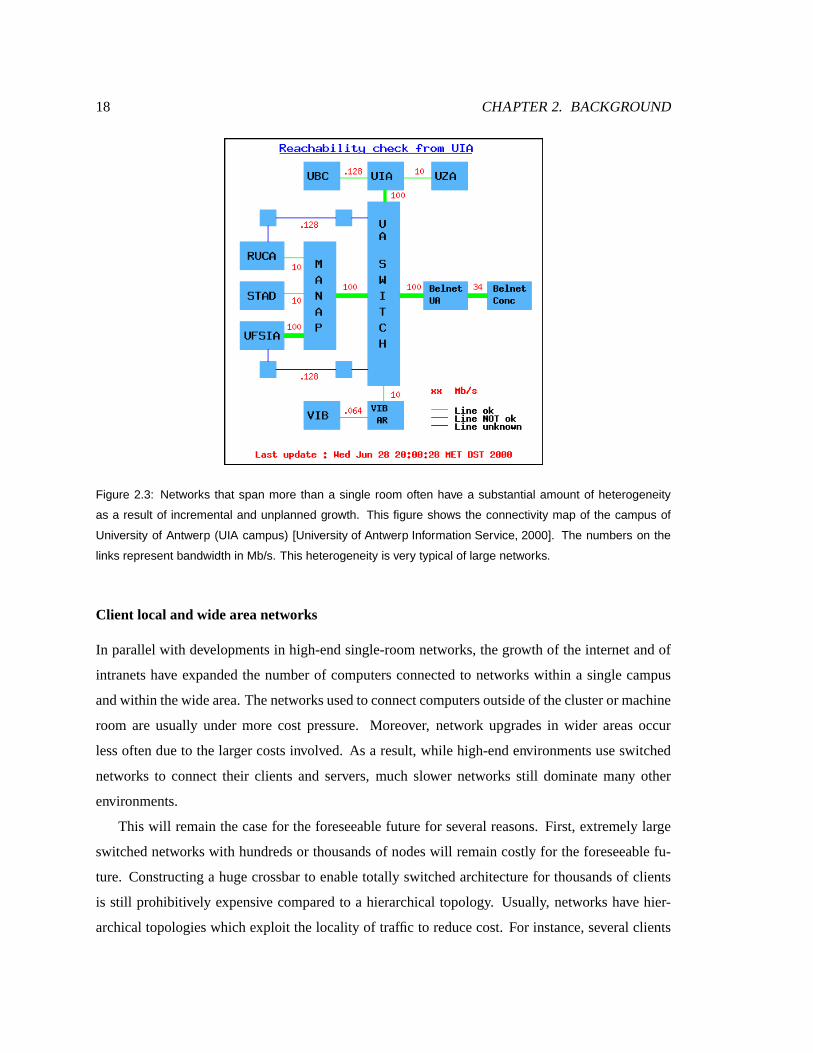
Figure 2.3: Networks that span more than a single room often have a substantial amount of heterogeneity
as a result of incremental and unplanned growth. This figure shows the connectivity map of the campus of
University of Antwerp (UIA campus) [University of Antwerp Information Service, 2000]. The numbers on the
links represent bandwidth in Mb/s. This heterogeneity is very typical of large networks.
Client local and wideareanetwork s
In parallel with developments in high-end single-room networks, the growth of the internet and of
intranets have expandedthe number of computersconnected to networks within a single campus
and within thewidearea.Thenetworksused to connect computersoutsideof thecluster or machine
room are usually under more cost pressure. Moreover, network upgrades in wider areas occur
lessoftendueto the larger costs involved. As a result, while high-end environments useswitched
networks to connect their clients and servers, much slower networks still dominate many other
environments.
This wil l remain thecase for the foreseeable future for several reasons. First, extremely large
switched networks with hundredsor thousandsof nodeswill remain costly for the foreseeable fu-
ture. Constructing a huge crossbar to enable totally switchedarchitecture for thousands of clients
is still prohibitively expensive compared to a hierarchical topology. Usually, networks have hier-
archical topologies which exploit the locality of traffic to reducecost. For instance,several clients

2.2. APPLICATION DEMANDS ON STORAGE SYSTEMS 19
in a department may share a high-bandwidth switched network, but connect to other departmen-
tal networks via a lower-bandwidth link. In this manner, bottlenecks can be avoidedmost of the
time. However, for certain traffic and datadistribution patterns, “bottleneck links” can severely
limit application responsetime.
Second, distributed filesystemsare expected to expand into private homes to provide users
with better and more uniform data access and management software between home and office.
Bandwidth to the homecontinuesto make step increaseswith the introduction of cable modems,
ISDN andADSL. Although thesetechnologiesareseveral timesfaster than traditional phone-based
modems,they are still limited to 1 to 2 Mb/s of bandwidth at best, andstill substantially slower
thanstandardLAN technologies suchas 10 Mbit and 100Mbit Ethernet. Figure2.3 il lustratesthe
bandwidthheterogeneity in an actual deployed network.
2.2 Application demandson storagesystems
Traditional aswell asemerging applications makethree important demands on storage systems.
First, application storagerequirementsaregrowing at a rapid pace,oftenreaching 100% per year.
Second, continuous data availabili ty remains a pressing demand for most organizations. Third,
many emerging applications employalgorithmsthat require high-bandwidth accessto secondary
storage.
2.2.1 Flexible capacity
Storage requirements are growing at a rapid pace. The explosive growth of electronic commerce
is generating massive archives of transaction records documenting customerbehavior and history
aswell inter-businesscommerce. Medical applicationssuch asimagedatabasesof treatedpatient
cells are generating massive archives of multimedia objects. Scientific applications continue to
generatemassive repositories of geological and astronomical data. A large and growing number
of applicationsfrom real-time astronomy, businessand web data mining, and satellite data storage
and processing are require massive amounts of storage. This storage must be distributed across
storagedevicesto providethenecessarybandwidthandreliability. For example, thestorageof audio
information from 10 radio stations for one yearrequires 1 TB of disk space. Theaccumulation of
videoinformation fromonestation can fill up to 5 TB in asingleyear. Theaveragedatabasesizeof
a radiology department in ahospital is over6 TB [Hollebeek, 1997].

20 CHAPTER 2. BACKGROUND
OLTP File Servers$
Data WH%
Multimedia&0
'100
200
300
400(500
600
Ave
rage
ann
ual c
apac
ity g
row
th (
%)
Annual storage capacity growh(by application)
Figure 2.4: Annual average storage capacity growth by application. The storage needs of multimedia
and data warehousing applications are increasing at factors of three and five per year. The data is from
1997 [EnStor, 1997].
Figure 2.4shows that email and datawarehousing applicationsare themostdemanding in stor-
age capacity growth. Like many emerging data-intensive applications, theseapplications often do
not userelational databases but insteadusefilesystems or other custom non-relational data stores.
Search,multimedia and data mining represent threeimportant and commondata-intensive applica-
tions.
2.2.2 High availability
Down-time is increasingly unacceptable in on-line services. Table 2.5 shows the average cost of
down-timein dollarsperminutefor varioustraditional applications. Costsareexpectedto behigher
with the increasing importanceof on-line electronic commercewhere customerscanimmediately
turn to thenext service provider.
Theimportanceof dataavailabili ty requiresthat all storagebereplicated or protectedby redun-
dant copies. Furthermore,theneed to recover site disastersrequiresthatdataberemotely replicated
or “backed up” regularly. It is crucial that data be accessible at acceptable latenciesduring these
management operations.
2.2.3 High bandwidth
Many web and business applications are fundamentally concerned with extracting patterns from
large amounts of data. Whether it is a pattern in customershopping preferences, or a pattern in

2.2. APPLICATION DEMANDS ON STORAGE SYSTEMS 21
Application Cost of down-time
($ per minute)
ERP 13,000
Supply Chain Management 11,000
Electronic Commerce 10,000
ATM/EFT/POS 8,500
Internet Banking 7,000
Universal Personal Services 6,000
Customer ServiceCentre 3,700
Table 2.5: Average cost of down-time for various applications. The actual cost varies depends on the particular
organization. ERP stands for enterprise resource planning software, which performs several tasks such as
sales and billing, inventory management and human resource related processing. The numbers are reported
by Stratus Technology [Jones, 1998].
links among home pageson the web, many emerging applications are concerned with extracting
“patterns” or “knowledge” frommassive data setswith li ttle structure. This translates into multiple
passesover thedatato test, refineandvalidatehypotheses.
Multimedia applications
Thegrowingsizeof datasetsismaking search afrequent andimportant operation for alargefraction
of users. From email messagesto employeerecordsto researchpapersand legaldocuments, search
is probably one of the most frequently executed operations. While indexing can help reduce the
amount of datathat mustberead from secondarystoragefor someapplications,it is not effectivefor
searching emerging multimedia and temporal databases, and for data archiveswithout a structured
schema.
Image databases,for example, oftensupport queriesby image content. Usually, theinteresting
features(e.g. color, texture, edges...) of the imageare extractedandmappedonto feature vectors
which represent the“fingerprint” of theimage. Each imageor multimedia object is associatedwith
a featurevector, which is storedwhen theimageis enteredin thedatabase.Featurevectorsareused
for content-based search. Performing thesearch in the “feature space” reducesthe need to access
“raw” objects. A feature vector contains several numerical attributes. Thenumber of attributes in
thevector is known asthe “dimensionality” of thevector andcorrespondingly of thedatabase.

22 CHAPTER 2. BACKGROUND
Thedimensionality of thefeaturevector is usually largebecausemultimedia objectsoftenhave
several interesting featuressuch as color, shape, and texture, and becauseeachfeature is usually
represented by several numerical attributes. For example, color can be represented by the per-
centage of blue, red and greenpixels in the image. Research on indexing multidimensional and
multimedia databases has made significant strides to improve access latencies. Grid-basedand
tree-based schemes such as R-trees and X-treeshave been proposed to index multidimensional
databases.Tree-baseddatastructuresgeneralizethetraditional B-treeindex by splittingthedatabase
into overlapping regions. However, as the number of attributesthat a query is conditioned on in-
creases,the effectiveness of theseindexing schemes becomesseverely limited. As dimensionality
increases, a rangeor a nearest neighbor query requires accessing a relatively large portion of the
data set[Faloutsos,1996]. Becausedisk mechanics heavily favor sequential scanning over random
accesses,an indexing datastructurethat requiresmany randomdisk accessesoften performsslower
than sequential scanning of the dataset. Thus, while these data structureshave proven effective
for low dimensionality data, they are of lit tle value in indexing higher dimensionality data. Simple
sequential scanning of thefeaturevectors thereforebecomespreferable to index-basedsearchsince
sequential disk accessbandwidthsaremuch higher thanrandom accessbandwidths.
The inherent largedimensionality of multimedia objects and thetendency of search queries to
conditiononmany dimensionsatonceis known asthe“dimensionality curse”. Temporal databases,
which storesequences of time-basedsamplesof data, such as video framesor daily stock quotes,
are alsoplagued with the dimensionality curse. These databasesoften support “query by example”
interfaces,wherethe user provides anexample sequenceandasks for similar onesin thedatabase.
For example, a brokermaysearch for all stocks that movedsimilarly over a given timedperiod. A
stock isoften representedby ahighdimensionality vector, corresponding to the“fingerprint” of the
stock in the timeor frequency domain [Faloutsos,1996].
Data mining
Businesses are accumulating large amounts of data from daily operation that they would like to
analyzeand “mine” for interesting patterns[Fayyad,1998]. For instance,banks archive records of
daily transactions, department storesarchive records of point-of-sale transactions, online-catalog
servers archive customer browsing and shopping patterns. This information contains interesting
patternsand “knowledgenuggets” about customer profilesthatmanagement would like to discover
and exploit. Typical data mining operations search for the likelihood of certain hypotheses by
2.3. REDUNDANT DISK ARRAYS 23
analyzing the datafor thefrequency of occurrenceof certain events. Most datamining algorithms
requiresequential scanning, oftenmaking multiplepassesover thedata.
Oneexample of adatamining application is onethatdiscoversassociation rulesin salestransac-
tions[Agrawal and Srikant, 1994]. Givencustomerpurchaserecords, the application extracts rules
of the form “i f a customer purchasesitem A and B, thenthey are also likely to purchaseitem X.”
This informationenablesstoresto optimize inventory layout.
Datamining applicationscompriseseveral components,someof which aredata-intensive (data
parallel), and others aremore memory andCPU intensive. Frequentsets counting applications, for
example, start counting the occurrencesof pairs of items,triplets, four tuples, etc. in consecutive
passes. Thelaterpassesaccessthesecondary storagesystemlessandless, consumingmoreCPUas
their working set fit in mainmemory.
Summary
Emerging important applicationsare data-intensive, comprising at least one component which se-
quentially scans thedataset. Such applicationsrequire high-bandwidth storagesystems.They also
placepressureon interconnectsby processing largeamountsof data. They, therefore,would benefit
from techniques thatminimizedatamovement especially overslow and overloaded networks.
2.3 Redundant disk ar rays
Emerging applications require massive data sets, high-bandwidth and continuousavailability. This
dissertation proposes a storagesystem architecture that providesscalable capacity and bandwidth
while maintaining high-availability. This research builds on previous work in high-availability and
high-bandwidth storagesystems, in particular disk arraysand transactional systems. Thefollowing
sectionsprovidenecessary backgroundon these two topics.
Traditionally, filesystemswere contained completely on a single storage device. To allow file
systemsto belargerthanasinglestoragedevice, logicalvolumemanagersconcatenatemany storage
devicesunder theabstraction of asingle logical device. Logical volumemanagersperform apartof
the storage management function, namely the aggregation of multiple devicesto look like a single
one while employing a simple round-robin load balancing strategy across the devices. A logical
volume manager is typically implemented in softwareasa device driver, and at most hasa small
effecton performance.

24 CHAPTER 2. BACKGROUND
)+*-,/.102*43 )+*-,/.102*45 )+*-,/.102*46798:<;:<8 =?>A@CBD>FEHG?IJBLKAEHG?IJBNM:PO
)+*-,/.102*4Q
:SR:<T:<U 79;:PV7WO:<X :PY
Z�[/\^]`_`a�b-_c\�]`d�e
Figure 2.5: Layout of data and parity blocks in a RAID level 5 system. Data blocks within a stripe are protected
by a parity block which is the cumulative XOR of the data blocks. The parity block is rotated around the devices
in an array. Each write to any of the disks needs to update the parity block. Rotating the parity block balances
the parity write traffic across the devices.
In thelate 1980s, in order to bridge theaccess gap betweenthe storage subsystemandthe pro-
cessors, arraysof small, inexpensivedisks(RAID) wereproposed [Pattersonet al., 1988] to replace
largeexpensivedisksystemsandautomateloadbalancingbystripingdata[M. Livny andBoral, 1987].
RAID arrays providetheillusion of a single logical devicewith high small- request parallelism and
large-request bandwidth. By storing a partially redundant copyof thedata asparity on one of the
disks,RAIDs improvedreliability in arrayswith ahigh numberof components.
2.3.1 RAI D level 0
RAID level 0 writesdata across thestoragedevicesin an array, onesegment at a time. Reading a
large logical region requiresreading multiple drives. Thereadscanbeservicedin parallel yielding
N-fold increasesin accessbandwidth.
This technique is known as “striping”. Striping also offers balanced load across the storage
devices.When avolume isstriped acrossN devices,random accessesto thevolumeyield balanced
queuesat the devices. Striping is known to remove hot-spots if thestripeunit sizeis much smaller
thanthetypicalworkloadhot spot size.
2.3.2 RAI D level 1
RAID 0 is not fault-tolerant. A disk failure results in data loss. RAID 1 writes a data block to two
storagedevices,essentially replicating thedata. If onedevice fails, data canbe retrieved from the
replica. This processis also called “mirroring.” Mirroring yields higher availabilit y but imposesa
highcapacity cost. Only half thecapacity of astoragesystemis useful for storing userdata.
When replication is used, reads can be serviced from both replicas and load canbe balanced

2.3. REDUNDANT DISK ARRAYS 25
fggghji-kml�ion�prq-s t?nvu1wxq
fgggh yzkm{#q-i-|rsj}�~r|ru1�j�rs t�n�uxwxq
fggghj�-kz{�q2�-~r�r��w n��r�-wxs t?n�uxw1q
���`��� � �`��� � �� ����� ��������� 82�� ����� �������2� 82��+�`���� � �2�c���9� ;2� � �c�c� � �� � �2�c����� ;2� � ����� �������2� 82� � � �2�c����� ;2�
Figure 2.6: RAID level 5 host writes and reads in the absence of faults. An arrow directed towards a device
represents a physical device write, while an arrow originating at a device represents a read from the device.
The + operation represents bitwise XOR. Different protocols are used depending on the number of units
updated: A large write where all units are updated is shown in (a), a read-modify-write where less than half
of the data units in a stripe are updated is shown in (b), a reconstruct write where the number is larger than
half is shown in (c). Some update protocols, like those shown in (b) and (c), consist of two-phases separated
by a synchronization point at the host. I/Os labelled by a (1) are performed in a first phase. At the end of this
phase, the new parity is computed and the parity and data are updated in a second phase (arrows labeled by
a (2)).
by selecting one copy at random, through round-robin selection, or by selecting thedisk with the
shortestqueue.
2.3.3 RAI D level 5
RAID level 5 employs a combination of striping and parity checking. Theuseof parity checking
providesredundancy without the 100% capacity overheadof mirroring. In RAID level 5, a redun-
dancy codeiscomputedacrossaset of datablocksandstoredon an otherdevice in thegroup. This
allows the systemto tolerateany single self- identifying device failure by recovering data from the
failed deviceusing theother datablocksin thegroupandtheredundant code[Patterson etal., 1988].
The block of parity that protects a set of dataunits is called a parity unit. A set of dataunits and
their corresponding parity unit is calleda parity stripe. Figure 2.5depicts the layout of blocksin a
RAID level 5 array.
Writeoperationsin fault-freemodearehandled in oneof threeways,depending on thenumber
of units being updated. In all cases,the updatemechanisms are designedto guarantee theproperty
thatafter thewrite completes,theparity unit holdsthecumulativeXORover thecorresponding data
units. In the caseof a large write (Figure 2.6(a)), since all the data units in the stripe are being
updated, parity can becomputedby thehost asthe XOR of thedata units and thedata and parity
blockscan bewritten in parallel.

26 CHAPTER 2. BACKGROUND
hji2km{#q-�-~r�r��w n��r�-wxs t?n�uxw1q h��-km�Sqvp�n�i-|rq-|rsj{#q-i-|fgggfggg
h yzkm{#q-i-|rsj}�~r|ru1�j�rs t�n�uxwxqfg g g
Figure 2.7: RAID level 5 host writes and reads in the presence of a fault. An arrow directed towards a device
represents a physical device write, while an arrow originating at a device represents a read from the device.
The + operation represents bitwise XOR. A device marked with an X represents a failed device. Different
write protocols are used depending on whether the blocks on the failed device are being updated or not. If
the failed device is being updated, the blocks on the surviving devices are read in a first phase, and the new
parity computed by XORing these blocks with the block that was intended to be written to the failed device.
As a result of the parity update, the update of the failed device is reflected in the parity device. This algorithm
is shown in (a). If the failed device is not being updated, then the read-modify-write algorithm shown in (b) is
used. A read request that touches the failed device is serviced by reading all the blocks in the stripe from the
surviving devices and XORing them together to reconstruct the contents of the failed device (c).
If less thanhalf of thedata units in a stripe are being updated, the read-modify-write protocol
is used (Figure 2.6(b)). In this case, the prior contents of the data units being updated are read
and XORedwith the new data about to be written. This produces a mapof the bit positions that
needto be toggledin theparity unit. Thesechanges areapplied to theparity unit by reading its old
contents, XORing it with the previously generated map, and writing the result back to the parity
unit. Reconstruct-writes(Figure2.6(c)) areinvoked when thenumber of dataunits is morethanhalf
of thenumberof dataunits in aparity stripe. In this case,thedataunitsnot being updated are read,
and XORedwith thenew data to compute the new parity. Then, the new data units and theparity
unit arewritten. If a device hasfailed, thedegraded-mode write protocols shown in Figure 2.7(a)
and Figure2.7(b) areused. Dataon thefaileddeviceis recomputedby reading theentirestripeand
XORing the blocks together asshown in Figure 2.7(c). In degradedmode, all operational devices
areaccessedwheneverany device is read or written.
2.4 Transactions
This dissertation proposesa scalable storage architecture basedon giving clients direct accessto
storage devices over switched networks. In such a system, multiple clients can be concurrently

2.4. TRANSACTIONS 27
accessing shareddevices. Proper algorithmsmust be devised to ensure correctnessin thepresence
of concurrentshared accessesand also to ensureprogressin theeventof untimely failuresof clients
and devices.For thestoragesystem to bescalable, theseprotocolsmustalsoscalewell with system
size avoiding centralizedbottlenecks. Transactions were developed for fault-tolerant, concurrent-
access databasesystems,and later applied in the construction of other fault-tolerant distributed
systems. Chapter 4 proposesan approach based on a storage-specializedtransactions and based on
distributed protocols that exploit trends towards increased device intelligence to distribute control
work to theendpointsavoidingcentralization.
BecauseChapter 4 buildson previouswork in databasetransaction theory, abrief review of the
mainconcepts in thatfield isnecessary. This section reviews transaction theory asabackgroundfor
thediscussionsin Chapter4. Thissection maybeskippedby readerscomfortable with transactions
and with databaseconcurrency control and recovery algorithms.
Databasesystemsweredevelopedto support mission-critical applications requiring highly con-
current and highly available accessto shared data by a large number of users. A databasesystem
comprisestwo components that are responsible for this: a concurrency control component anda
recovery component. Concurrency control refersto theabilit y to ensureconcurrent usersconsistent
access to the data despite the fact that theexecution of their operations may be interleavedby the
database engine. Recovery refers to the ability of the databaseto tolerate software and hardware
failuresin themiddle of an operation.
A central concept in database systems is thatof a transaction, a program unit which performs
a sequence of readsand writes to items in the database, with the accesses usually separated by
some computation. A transaction is guaranteedto have strong correctnesspropertiesin theface of
concurrency andfailures,and is theunit on which thedatabasesystemprovides theseproperties.
2.4.1 Transactions
Database transactions [Gray etal., 1975, Eswaran etal., 1976] have four core properties, widely
known astheACID properties [HaerderandReuter, 1983, GrayandReuter, 1993]:
� Atomicity: This is the“all or nothing” property of transactions. A transaction’s effects wil l
eitherbecompletedin their entirety or noneof themwill reach thedatabase, even in thecase
of untimely failures.
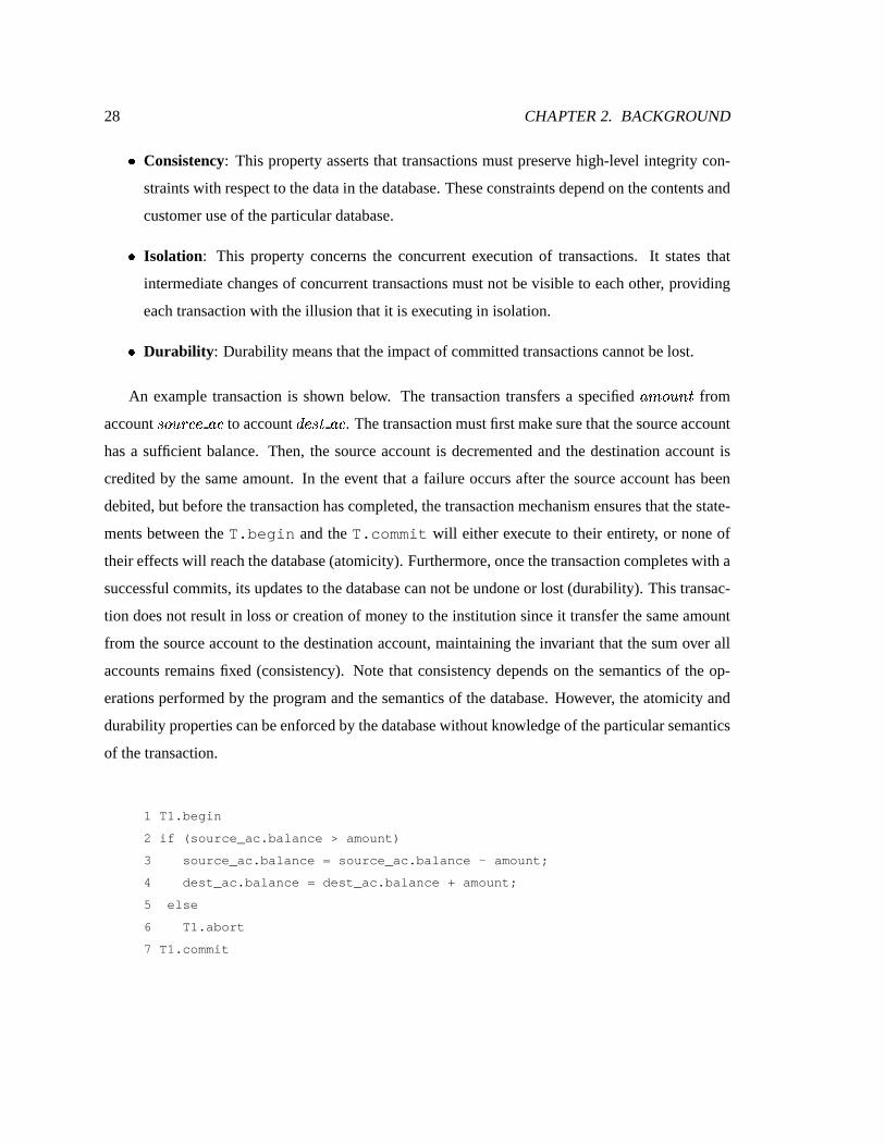
28 CHAPTER 2. BACKGROUND
� Consistency: This property asserts that transactionsmust preserve high-level integrity con-
straintswith respectto thedata in thedatabase. Theseconstraintsdependon thecontentsand
customeruseof theparticular database.
� I solation: This property concerns the concurrent execution of transactions. It states that
intermediatechangesof concurrent transactionsmust not bevisible to each other, providing
eachtransactionwith theillusion that it isexecuting in isolation.
� Durabili ty: Durability meansthattheimpactof committedtransactionscannot belost.
An example transaction is shown below. The transaction transfersa specified �9���z�4 �¡ from
account ¢£�z�S¤z¥�¦ �#¥ to account §W¦m¢£¡ ��¥ . Thetransactionmustfirst makesurethat thesourceaccount
has a sufficient balance. Then, the source account is decremented and the destination account is
credited by the same amount. In the event that a failure occurs after the source account hasbeen
debited, but before thetransaction hascompleted, the transactionmechanismensuresthat thestate-
ments between the T.begin and theT.commit will eitherexecute to their entirety, or none of
their effectswill reachthedatabase(atomicity). Furthermore, oncethetransaction completeswith a
successful commits, its updatesto thedatabasecan not beundoneor lost (durability ). This transac-
tion doesnot result in loss or creation of money to theinstitution sinceit transfer the sameamount
from the source account to the destination account, maintaining the invariant that thesum over all
accounts remains fixed (consistency). Note that consistency depends on the semantics of the op-
erationsperformed by theprogramand thesemantics of the database. However, the atomicity and
durability propertiescan beenforced by thedatabasewithout knowledgeof theparticular semantics
of thetransaction.
1 T1.begin
2 if (source_ac.balance > amount)
3 source_ac.balance = source_ac.balance - amount;
4 dest_ac.balance = dest_ac.balance + amount;
5 else
6 T1.abort
7 T1.commit

2.4. TRANSACTIONS 29
2.4.2 Serializability
Database systems must execute transactions concurrently to meet demanding throughput require-
ments. This concurrency must not result in incorrect behavior. To reason about the correctness
of concurrent transactions, we canabstract thedetails of the transaction programand focuson the
accessesthat it makesto thedatabase. A transaction isdescribedsimply asa sequenceof ¤�¦£��§ and¨ ¤ª©v¡«¦ requests to data itemsin the database. For example, theaccount transfer transaction above
issues a ¤�¦£��§ to thesource account (Line2) to makesure it hasenough funds, thenissues a ¨ ¤ª©v¡«¦to decrement thesourceaccount by thetransferredamount (Line 3) and finally issuesa ¨ ¤m©-¡2¦ to the
destination account to increment it with thetransferredamount (Line4).
Accesses to data itemsby a transaction aredenoted by ¤�¬ ¯® and ¨ ¬ ¯® where is the dataitem
being accessed. More precisely, ¨�° ¬ ¯® denotes a write by transaction ± ° to dataitem . ² ° and ³ °denoteacommit andanabort of transaction ± ° respectively.
Using this terminology, a transaction that transfers funds from account to account ´ then
finally commitscan bedescribedas:
±¶µ?·¸¤�µ�¬ 4® ¨ µm¬ ¯®¹¤�µ£¬ ´W® ¨ µ�¬ ´9®º²»µ
whilea transaction that eventually abortscanbedescribed as:
±¶µ?·¸¤�µm¬ ¯®H³¼µ
In thiscase,thetransactionabortsafterreading thesourceaccount anddiscoveringthat it does
not haveenough fundsto cover theamount that needsbetransferredto thedestination account ´ .
Concurrent executionsof transactionsaredescribed by execution historieswhichshow how the
accessesperformedby thetransactions interleavewith eachother. An examplehistory showingtwo
transactions is ½ºµ :
½ºµ�·¸¤�µm¬ ¯® ¨ µ£¬x¯®L¤�µm¬ ´W® ¨ µ�¬ ´9®¾²»µ¿¤�À�¬ ¯® ¨ À�¬ 4®¹¤�À�¬xÁª® ¨ À�¬ Á�®H²AÀ
½ µ shows two transactions ± µ and ± À . ± µ transfersa given amount from source account to
destination account ´ . ±�À transfers anotheramount from sourceaccount to destination account Á .½ µ iscalledaserial history. A serial executionhistory is onewhereonly onetransaction isactiveat

30 CHAPTER 2. BACKGROUND
a time,anda transaction starts and finishes beforethe next onestarts. Indeed, in the history above,
± µ executesto completion andcommitsbefore ± À starts.
The traditional correctnessrequirement for achieving isolation of databasetransactions is se-
rializabili ty [Papadimitriou,1979]. A history is said to beserializable if its results are equivalent
to a serial execution. Thenotion of equivalenceis often definedin terms of the“ reads-from” rela-
tionship. A transaction ± ° is said to “ read from” ±¯Â if there is no accessto between ¤ ° ¬ 4® and¨ Â9¬ 4® . Two executions ½ µ and ½ À areequivalentif they contain thesamesetof transactions,if they
establish the same“reads from” relationship betweentransactions, if the final value of each data
itemin thedatabaseis writtenby thesametransaction in both histories1, and if thetransactionsthat
commit (abort) in onealsocommit (respectively abort) in theother.
For example, the following execution ½¹À is serializable:
½ À ·¸¤ µ ¬ 4® ¨ µ ¬ ¯®L¤ À ¬ 4®¹¤ µ ¬ ´9® ¨ µ ¬ ´9®¾² µ ¨ À ¬ 4®¹¤ À ¬xÁª® ¨ À ¬ Á�®H² À½LÀ is serializablebecauseit is equivalent to aserial history, namely ½ºµ above. In bothhistories,
± µ and ± À eventually commit. The final value of and the finally value of ´ areboth written by
transaction ±�À in both histories. Finally, both histories establish the samereads-from relationship:
in both histories, ± À reads from ± µ .Using this definition for serializability, theexecution below isnot serializable:
½LÃÄ·¸¤ µ ¬ 4®¹¤ À ¬ ¯® ¨ µ ¬ 4®¹¤ µ ¬ ´9® ¨ µ ¬ ´9®¾² µ ¨ À ¬ 4®¹¤ À ¬xÁª® ¨ À ¬ Á�®H² À½ à is not serializable becausethereis no equivalentserial history thatsatisfiesall theconditions
of equivalencedescribedabove. In particular, ±+À doesnotread from ±¶µ so ±�À must appear before ±¶µin anequivalentserial history. At thesametime, however, thefinal valueof dataitem is written
by ± À so ± À mustappearafter ± µ in an equivalent serial history. Hence, the impossibility of the
existenceof sucha serial history.
2.4.3 Seri alizability protocols
Serializabilit y hasbeen traditionally ensured using one of threeapproaches: locking, optimistic,
and timestampordering methods. Eachisasetof rulesfor whenanaccesscan beallowed, delayed,
abortedor retried.1That is, if Å#Æ is thelasttransactionto write to Ç in one history, it is also the last one to write to Ç in theother.

2.4. TRANSACTIONS 31
Batch locking
Therearetwo widely usedlocking variantsthat achieveserializability : batch locking and two-phase
locking. Batch locking is the most conservative approach. Locks on shared data itemsare used to
enforcea serial order on execution. All locks are acquired when a transaction begins and released
after it commits or aborts. It can be shown that executions allowed by this locking schemeare
serializable. Precisely, theexecutionsareequivalent to aserial onewheretransactionsappear in the
orderof their lockacquisition time.
Batch locking has theadvantage thatit is simple to implement. Furthermore, it doesnot leadto
deadlocks becauseall locksare acquired at the sametime. Therefore, there is no “hold-and-wait”,
anecessary condition for deadlocks to occur [Tanenbaum, 1992]. Thedisadvantageof thisscheme
is thatit severely limits concurrency since locksblockingaccessto data fromother transactionsare
potentially held for a long period.
Two-phaselocking
Significant concurrency canbeachievedwith two-phaselocking [Grayet al., 1975], alockingscheme
wherelocksmaybeacquiredoneatatime, but nolock canbereleased until it is certainthatno more
lockswill beneeded. Two-phase lockingallows higherconcurrency thanbatch locking, although it
is still susceptible to holding locks for a long period of time while waiting for locks held by other
transactions. This is becauselocks are acquired when the item is first accessed and must be held
until thelast lock that wil l beneededisfinally acquired.
Unlikebatch locking, two-phaselocking is susceptible to deadlocks. Consider two transactions
±Èµ and ±+À that both want to write to two dataitems and ´ . Suppose that ±¶µ acquired a lock on
and then ± À acquired a lock on ´ . Now, ± µ requests the lock on ´ and ± À requests the lock on
. Both transactionswill block waiting for theother oneto release theother lock. Because of the
two-phasenature of the locking protocols, a transaction can not release any locks until it has no
morelocksto acquire. So, neither transaction wil l releasethelock needed by theother, resulting in
adeadlock.
When two-phaselockingis employed, adeadlock avoidanceor detection andresolution strategy
mustalso be implemented. Deadlocks can be preventedby ordering all thepossible locks and then
enforcing adisciplinethat require that locksareacquiredin agivenorder. Thisbreaks the“circular
wait” condition that is apre-requisite for deadlocksto occur.
Deadlockscan also be detectedand resolved by aborting the appropriate blockedtransactions.

32 CHAPTER 2. BACKGROUND
Deadlockscanbedetectedby recording thedependenciesif all dependenciescan beenumerated and
if the overheadof maintaining thedependency information is not prohibitive. Distributedsystems
can exhibit deadlocks involving transactions at multiple nodes requiring dependency information
distributed acrosssites to be collected and merged to discover a deadlock. In this case, a simple
timeout basedscheme is likely to work better. If a transaction can not acquire a lock within a pre-
specified periodof time(thetimeout), it is suspected of being involvedin adeadlockand istherefore
abortedandrestarted.
Optimistic methods
Locking is also known as a pessimistic approach, sinceit presumesthat contention is commonand
that it is worthwhile to lock every data itembefore accessing it. Optimistic methodsare socalled
becausethey assume conflict is rare and do not acquire locks before accessing shared data but
insteadvalidateat commit timethata transaction’sexecutionwasserializable [Eswaranet al., 1976,
KungandRobinson, 1981]. If a serializability violation is detected, the transaction is abortedand
restarted.
Optimistic protocols are desirable when locking and unlocking overheadis high (e.g. if it in-
volves network messaging), when conflicts arerare or when resourcesare plentiful and would be
otherwiseidle (e.g.multiprocessors).
Timestamp order ing
Timestamp ordering protocols selectana priori order of execution using someform of timestamps
and then enforce that order [BernsteinandGoodman, 1980]. Most implementations verify times-
tamps astransactionsexecute readand write accessesto thedatabase,but the moreoptimistic vari-
antsdelay thechecksuntil commit time [Adyaetal., 1995].
In thesimplesttimestamporderingapproach,each transaction is taggedwithauniquetimestamp
at thetime it starts. In order to verify that readsandwrites areproceeding in timestamp order, the
database tagseachdata item with apair of timestamps, rtsandwts, whichcorrespond to thelargest
timestamp of a transaction that read and wrote the data item, respectively. Basically, a readby
transaction ± with timestamp �/ɯ¡«¢WÊ^±ÌË to data item Í is accepted if �/É4¡«¢WÊ^±ÌËÏÎ ¨ ¡«¢�Ê�Í#Ë , otherwiseit
is (immediately) rejected. A write is accepted if �/É4¡2¢�Ê^±ÄËÐÎ ¨ ¡Ñ¢WÊ�Í¯Ë and ��ɯ¡Ñ¢�Ê^±ÄËÐÎÒ¤m¡«¢�Ê�Í#Ë . If an
operation is rejected, its parent transaction is abortedandrestartedwith anew larger timestamp.
To avoid theabort of onetransactioncausingadditional transactionsto abort, asituation known

2.4. TRANSACTIONS 33
ascascading aborts, reads areusually not allowed to read data itemspreviously written by active
(uncommitted) transactions. In fact, whenanactive transaction wants to updatea data item,it first
submits a “prewrite” to thedatabasedeclaring its intention to write but without actually updating
the data. The database accepts a prewrite only if �/É4¡2¢�Ê^±Ä˺Π¨ ¡Ñ¢�Ê�Í¯Ë and �/É4¡«¢9Ê�±Ó˾ÎÔ¤ª¡2¢�Ê�Í�Ë . A
prewrite is committed when the active transaction ± commitsand a write is then issued for each
submittedprewrite. Only then is thenew valueupdatedin thedatabaseandmadevisible to readers.
A transaction that issued a prewrite may abort, in which caseits prewrites arediscarded and any
blockedrequestsareinspected in casethey canbecompleted. If a prewrite with ��ɯ¡«¢�Ê^±ÄË hasbeen
provisionally acceptedbut not yet committedor aborted, any later operationsfrom a transaction ±»Õwith �rÉÖ¡Ñ¢WÊ�± Õ ËAÎ×��ɯ¡Ñ¢�Ê^±ÄË areblockeduntil theprewritewith �rÉÖ¡Ñ¢WÊ�±ÄË is committedor aborted.
Toprecisely describethealgorithmsexecutedby thedatabaseuponthereceipt of aread,prewrite
or write request, a few more variablesmust be defined. To simplify the presentation of the algo-
rithms,we will assumethat the databasecontains a single dataitem,say Í . Each data itemhasa
queue of pending requests. We denote by �¾©v �¤z¡«¢WÊ�Í�Ë the smallest timestampof a queued read to
data item Í , while �º©- WÉÖ¡Ñ¢WÊ�Í#Ë represents the smallest timestampof a queued prewrite to Í . The
algorithm executedupon the receipt of aprewrite request can bedescribedas follows:
prewrite(v, opts)
if (opts < rts(v)) then
// opts is too far in the past
return REJECT;
else if (opts < wts(v)) then
// opts is too far in the past
return REJECT;
else
// opts bigger than the timestamp of any
// transaction that read or wrote this item
// accept and put it on the prewrite queue
enqueue(prewrite, v, opts);
minpts(v) = MIN (minpts(v), opts);
return(ACCEPT);

34 CHAPTER 2. BACKGROUND
Writesare always accepted becausethe corresponding prewrite wasalready accepted. Writes
maybequeueduntil readswith lower timestampsareserviced. Whenawrite is processed, its corre-
sponding prewrite is removed fromtheservicequeue. Processingawrite could increase �º©� �É4¡«¢9Ê�Í#Ë ,resulting in some reads being serviced. By setting a special flag, the write algorithm triggersthe
database to inspectany requestsqueued behind theassociatedprewrite.
write(v, opts)
if (opts > minrts(v) || opts > minpts(v)) then
// there is a read ahead of us in the queue
// so we’ll wait so we can service it before
// we update the data item and force it to be rejected
// or there is a prewrite before us
enqueue(write, v, opts);
else
// write data item to stable storage and update wts
// set the flag so we scan the queue of waiting requests
write v to store;
dequeue(prewrite, v, opts);
wts(v) = MAX (wts(v), opts);
inspectQueue = true;
In general, areadcanbeservicedeither immediately after it is received,or it maybequeued and
servicedlater. When a read is processed after being removed from the service queue, �¾©� +¤ª¡«¢9Ê�ͯËcould increaseandcausesomewrite requestsbecomeeligiblefor service. Whenareadis processed,
the inspectQueue flag is set, which causes the database to inspect the queue and see if any
queued(write) requestscanbeserviced. Similarly, whenawrite is processed, theinspectQueue
flag is setsothatqueued(readandwrite) requestsare inspectedfor service. Uponinspection of the
queue,any requeststhatcanbeserviced aredequeued, oneat a time,possibly leading to computing
new valuesof �¾©v �¤z¡Ñ¢�Ê�Í¯Ë and �¾©v #ÉÖ¡2¢�Ê�Í�Ë . Upon the receipt of a request to read data item Í by a
transaction with timestamp �/É4¡«¢ , thedatabaseexecutesthefollowing algorithmto decideto service
the read immediately, put it on thequeueof pending requestsor rejectit.

2.4. TRANSACTIONS 35
read(v, opts)
if (opts < wts(v)) then
return REJECT; // opts is too far in the past
else if (opts > minpts(v)) then
// there is a prewrite before opts
// we can not accept the read until we know
// the fate of the prewrite
// if the prewrite is later confirmed, this
// read should return a value that is more
// recent than the current value available now
enqueue(read, v, opts);
minrts(v) = MIN (minrts(v), opts);
else
// There is no prewrite in the queue ahead of opts
// so accept and update timestamp and set the flag
// so we scan the queue of waiting writes behind this read
rts(v) = MAX(rts(v), opts);
inspectQueue = true;
return committed value of v;
Figure 2.8 shows an example scenario ill ustrating how timestamp ordering works. Multiple
concurrent transactions areactive. They submit read, prewrite and write requests to the database.
All therequests addressa single data item in the database, denotedby . Therequestqueueshown
in thefigurerepresentstherequestswhicharepending to thatdataitem.Requestsarequeuedif they
cannot be handled immediately by thedatabaseasexplainedabove. Initially, hasan ¤z¡«¢ of Ø and
a ¨ ¡Ñ¢ of 12. The initial state of thedatabase also shows thata prewrite with �/ɯ¡Ñ¢HÙÚ��� hasbeen
acceptedby thedatabase.
The scenario proceeds as follows. First, the database receives a read with �/É4¡Ñ¢¿ÙÛ�£Ü . This
read is rejected because it is supposed to occur before a write which hasalready occurred. The
following read hasa timestamp of �/ɯ¡«¢�ÙÝ��Þ , later than any action that hasor is going to occur.
Sincethereis aprewritequeuedwith alower timestamp, this read cannot beserviced yetor theabort
of the transaction doing the write would force theabort of this transaction (becauseit reada value
that should have never been written). At this time, the databasecannot know whether theprewrite
will beconfirmedwith anactual write, or will beaborted. Thereadrequest is thereforeput on the
request queue behind the prewrite request. Shortly thereafter, a readwith �/ɯ¡«¢�ÙÝ��� is received.

36 CHAPTER 2. BACKGROUND
ß4à�á4â�ãä à�á4â�å�æ
ß�ç�è�éê�ë¶à�á4âìå�í
î ç�ï�ð�ç�á4àìñ�ð�ç�ð�ç
ß4à�á4â�å�òä à�á4â�å�æ
ß4à�á4â�å�òä à�á4â�å�ó
ß�ç�è�éê�ë¶à�á4â�å�í
ß�ç�è�éê�ë¶à�á4â�å�í
ë4ß�ç4ô ä ß�õ4à�çê�ë¶à�á4â�å�ó ö â�å�ó�í4÷ß4à�á4â�ã
ä à�á4â�å�æ
ø è4à�è�ù�è�á�ç
î�ú�û�ú�ü�ý
ß4à�á4â�å�íä à�á4â�å�óú�þ ë¶à�ÿ
ø ç�ï�ð�ç�ð�ç�é è���é á�ç�ß���õ���ç�é
ß�ç�è�é�� ö�� ê�ë¶à�á4â�å4÷�
�� �ìö â�å�ó�í4÷
��è��4â�å� �í4÷
é�è4à�è õ4à�ç þ ö è���éõ4à�á à�õ þ ç�á4à�è þ ë4á
ö â�å�ó�í4÷
ö â�å�ó�í4÷
ö â�å� �í4÷
ö â�å� �í4÷
ë4ß�ç4ô ä ß�õ4à�çê�ë¶à�á4â�å�ó��è��4â�å� �í4÷
ë4ß�ç4ô ä ß�õ4à�çê�ë¶à�á4â�å�ó��è��4â�å� �í4÷
��
�� �ìö â�å� �í4÷
ß�ç�è�é�� ö�� ê�ë¶à�á4â�å�í�
ß�ç�è�é�� ö�� ê�ë¶à�á4â�å�ò�
ä ß�õ4à�ç�� ö�� ��è��4â�å� �í4÷ �
ß�ç�è�é���ê�ë¶à�á4â�å�í�
ñ�ð�ç�ð�ç�é
î ç�ï�ð�ç�á4à�á à�ê è�����ç�á�áà���ç é�è4à�è õ4à�ç þ ö
ê�ë¶à�á4â�å�ó�
Figure 2.8: A sample scenario of a database using a timestamp ordering protocol. The database is assumed
to have a single data item Ç . At the outset, ��������Ç�� is � , and ��������Ç�� is �! , and the database has accepted
a prewrite with timestamp �#" . The figure shows changes to the database state and the request queue as
requests are received and handled. The hexagonal shapes represent requests and arrows show when a
request arrives to the database and when a response is generated. First, a read request with $&%'���)(*�,+ is
received and rejected, because �-�.� is �, . The read arrived too late since a transaction with timestamp �, has
already written to Ç and committed. Later, a read request with $/%'���0(1�,2 is received, because a prewrite with
a lower timestamp is in the queue, the read is queued. Some time later, a read with $&%3���4(5�!6 is received and
serviced updating ���.� . Finally, the write corresponding to the prewrite is received. It is serviced first, then the
queue is inspected and the read request with $7%3���4(5��2 is serviced, updating �,�.� and leaving the queue empty.
The reader can inspect that the execution allowed by the protocol is indeed serializable. In particular, it is
equivalent to the serial execution of Å�8�9#:<;�=�Æ?> (read) followed by Å�8�9#:@;�=�Æ?A (write) and finally followed by Å�8.9!:B;�=#ÆDC(read).
2.4. TRANSACTIONS 37
This read isserviced immediately because its ��ɯ¡«¢ exceeds ¨ ¡«¢ÌÙ �FE . Thecommittedvalueof x is
returnedin responseto this read. After thereadisserviced,thewrite corresponding to theprewrite
with �rɯ¡«¢ÄÙ ��� is received. It isserviced first, then thequeueis inspectedandthereadrequestwith
�/É4¡Ñ¢ÓÙ ��Þ is serviced, updating rtsand leaving thequeueempty.
2.4.4 Recovery protocols
The all or nothing recovery property provided by database systems is known as atomicity. The
recovery subsystemensures that all transactions meettheatomicity property in the faceof failures.
Therearethreekindsof failureswhich adatabasesystemmusthandle:
� Transaction failures. A transaction may decide to voluntarily abort. This abort is usually
induced by theprogrammer or the userwhenforwardprogress cannot bemadeor might be
better achievedby restarting thetransaction from thebeginning. In the caseof a transaction
failure, any updatesmadeby thefailed transaction to thedatabasemustbeundone.
� Systemfailures. Lossof the contents of volatile memory represent a system failure. In the
event of a systemfailure, transactions that committedmust have their effects applied to the
database on recovery. Any other active transactionswhich did not commit at the time of the
failuremusthave their updatesremoved fromthedatabaseto preserve theatomicity property.
� Media failures. Lossof the contents of non-volatile storage represent a media failure. This
requires restoring thedatabasefrom anarchival version.
A database is usually divided into disk pages, which are cached by a buffer manager. Active
transactions access the database pages by reading and writing items in the pages cached by the
buffer manager. Atomicity is achievedvia someform of “logging.” Logging is theaction of writing
a description of thetransaction to stable storage, not overwriting the “old” valuesof thedata items
that it intendsto update. Every time thetransaction writes a valuein volatile memory, that value is
written to the log. Whenthe transaction requests to commit, the valuesit intends to updateare all
on thelog. A final “commit” record is writtento thelog to marktheend of the new valueswritten
by thecommitting transaction. Oncethecommit record is written, theupdatedvaluescanbewritten
back to stablestorageat thebuffer manager’s leisure. No valuescan bewritten beforecommit time
however, unlesssuchupdatescanbeundoneat abort time.
One way logging can be used to achieve atomicity is as follows: if a failure occurs before
the “commit” record is written to the log, none of thevalues are updatedon the databaseand the

38 CHAPTER 2. BACKGROUND
transaction is considered to have aborted. This achievesatomicity since it enforcesthe “nothing”
effects,whereno effectswhatsoever from the transaction reach thedatabase.
If a failure occurs after the“commit” record is written to the log (commit point) but before all
thechangesareapplied to thedataitems,thenew valuescanbeapplied to thedatabaseby accessing
the log, thereby achieving the“all” effectandalsoachievingatomicity.
This logging technique is called Redo logging. It requires that a transaction that did not yet
commit never writes to stable storage. This requirement constrains the buffer manager, which can
not, forexample, evictadirty page(writtenby anuncommittedtransaction)back todiskby writing it
back to itsoriginal location. OthertechniquessuchasUndoandUndo/Redo[GrayandReuter, 1993]
also achieve atomicity but dictate different constraints on the buffer manager. An Undo record
recordsin thelog thecurrent committedvalueof theitem, allowing thebuffer manager to overwrite
thedatabasewith anuncommitted valueandstill ensurethatif aborted,theeffect of theuncommit-
ted transaction canbe removed.
Undo/Redo logging placestheleastamount of constraintsonthebuffer managerregarding when
blocksshould bewrittenbackto thedatabaseat theexpenseof more loggingwork.
2.5 Summary
Storagerequirementsaregrowing atarapid pace,oftenexceeding 100% peryear. Thisrapid growth
is fueled by theexplosion in theamount of businessdatawhich must bearchived for later analysis,
by theneedto store massive data sets collected from ubiquitoussensors andfrom satellites,and by
thepopularity of new data typesthat inherently contain more information suchasaudio andvideo.
Storagesystems are still predominantly based on magnetic disks, whose sequential transfer
rateshavebeen consistently improvingover thepastdecadeat anaverageof 40%peryear. Random
access times, on the other hand, dominatedby mechanical seek positioning, improvedmuchmore
slowly.
Processorshavemaintainedimpressiveratesof improvement, doubling inspeedevery18months.
Disk technology did not keep upresulting in asevere“I /O gap.” To bridgethegapbetweenprocess-
ing and I/O subsystems,disk arrays wereintroduced. Data is stripedacrossmultiple disks yielding
higher bandwidth from parallel transfers. Disk arrays rely on a single controller to implement the
striping andRAID functions.
Thepoint-to-point bandwidth available to a communicating pair of nodesin a high-endcluster
network have improvedat anaverage of roughly 45% per yearfrom 10 Mb/s in 1980 to 1 Gb/s in

2.5. SUMMARY 39
2000. Furthermore, theaggregate bandwidth available to an small 8 nodecluster hasjumped from
10 Mb/s in the 1980sto 8 Gb/s in 2000, thanks to switching technology that enablessimultaneous
communication from independentpairsof nodeswithout degradation in bandwidth. Machine room
networksoften usereliableswitchednetworkssuchasFibre-Channel, MyrinetandGigabit Ethernet
to build high-performanceservers fromclustersof commodity PCsanddevices.
The increasing transfer rates of storage devices place strong pressure on the single disk ar-
ray controller to deliver high-bandwidth to streamingapplications. Theconvergence of peripheral
storage and inter-processor networks point to an architecture that eliminates the single controller
bottleneck andallowsdirectaccessfrommultiple hoststo sharedstoragedevicesoverswitched net-
works. Suchasharedstoragesystempromisesscalablebandwidthbut introducesnew challenges in
ensuring correctness and availabilit y in the presence of sharing andconcurrency. Chapters3 and 4
describe such anarchitectureand thealgorithmsrequiredto ensurecorrectnessandscalabilit y.
Theconsistent increases in processing rateshave resulted in processors of variable speedsco-
existing in thesamecomputer system. Storageclients,smart devices,and disk array controllers all
tendto havedisparateamountsof processingandmemory whichvarybetweensites. Networkscon-
tinue to be quite heterogeneous in their bandwidth because of complex topologies, cost pressures
and thecoexistenceof several technology generations. This makesthestatic partitioning of function
acrossnodesof adistributedstoragesystemwithout regard to communication patternsand resource
availability undesirable in practice. Chapter 5 proposes an approach to automatically decide on
optimal functionplacement in adistributed storagesystem.

40 CHAPTER 2. BACKGROUND

Chapter 3
Network-attachedstoragedevices
Thischapterreviewstheargument madeby theNASDgroupatCarnegieMellon[Gibsonetal., 1997b,
Gibsonet al., 1998], and which statesthat current storagearchitecturesdo not scalecost-effectively
becausethey rely on file server machinesto copy data betweenstorage devices andclients. Un-
like networks, file server machines must perform critical functions in the midst of the datapath
and therefore must becustom-built (and expensive) to meet thedemands of bandwidth-hungry ap-
plications. Gibson et al. [Gibsonet al., 1997b, Gibsonetal., 1998] demonstrated that separating
filesystemcontrol messaging fromdata transfersimprovesscalability and reducescostby eliminat-
ing the file server from the data access path. Based on this architecture, this chapter proposes a
storageservicewherestoragestriping, aggregation andfault-tolerancefunctionsarealsodistributed
to the storage clients and the storagedevices, thereby eliminating the needfor the synchronous
involvementof acentralizedservermachine.
Thechapter is organized into two parts. The first part restatesthe principlesdevelopedby the
NASD group working at Carnegie Mellon from 1995 to 1999. In particular, Section 3.1 summa-
rizesthe trends that mandatechanging the current server-attached disk (SAD) architecture. Sec-
tion 3.2 describestwo network-attached storage architectures, network-attached SCSI (NetSCSI)
and network-attached secure disks (NASD), while Section 3.3 discusses the NASD architecture
in particular. A validation of the potential benefits of the NASD architecture was reported else-
where [Gibsonet al., 1997b, Gibsonetal., 1998] andis only briefly reviewed in this chapter.
Thesecond part of thechapter reports on a striping storage service on top of NASDs. NASD
enables clients to benefit from stripedparallel transfersfrom multiple devicesover switched net-
works. Section 3.4 describesa prototypestorage service, Cheops, which deliverson that promise.
Section 3.5 reports on the performance of bandwidth-hungry applications on top Cheops/NASD.
Section 3.6 describes alternative storagearchitecturesthat have beenproposedto providescalable
41
42 CHAPTER 3. NETWORK-ATTACHED STORAGE DEVICES
storage. Section 3.7summarizesthechapter.
3.1 Trendsenabling network-attachedstorage
Network-attachedstoragedevicesenabledirect data transfer betweenclient andstoragewithout in-
voking thefile server in commondataaccessoperations. This requiresrelatively important changes
both to hosts and storage devices. Such changesare becoming possible and compelling, however,
thanks to the confluence of several overriding factors: (1) the cost-ineffective scaling of current
storage architectures; (2) the increasing object sizes and data rates in many applications; (3) the
availability of new attachmenttechnologies; (4) the convergence of peripheral and interprocessor
switched networks,and; (5) anexcessof on-drive transistors.
3.1.1 Cost-ineffectivestoragesystems
Distributed filesystems[Sandberg et al., 1985, Howardetal., 1988] havebeen widely usedto allow
data to be stored and shared in a networked environment. These solutions rely on file servers as
a bridge between storage and client networks. In thesesystems,the server receives data on the
storage network, encapsulates it into client protocols, and retransmits it on the clients’ network.
This architecture, referred to asserver-attached disk (SAD), is illustrated in Figure 3.1. Clientsand
serversshareanetwork andstorageisattached directly to general-purposeworkstationsthatprovide
distributed file services. This is costly both becausethe file server hasto have enough resourcesto
handle bandwidth-hungry clients and because it often requires system administrators to manage
capacity andload balancing acrosstheserverswhenmultiple serversareused.
While microprocessor performance is increasing dramatically and raw computational power
would notnormally beaconcernfor afile server, thework doneby afile server isdata- and interrupt-
intensive and, with thepoorer locality typical of operating systems,faster processors will provide
much lessbenefit than their cycle timetrendspromise[Ousterhout, 1990,Chen and Bershad, 1993].
Typically, distributed file systemsemployclientcachingto reducethis serverload. For example,
AFS clients uselocal disk to cachea subset of the global system’s files. While client caching is
essential for high performance, increasing file sizes, computation sizes,andwork-groupsharingare
all inducing moremisses per cache block [Ousterhout etal., 1985, Baker etal., 1991]. At thesame
time, increasedclient cachesizesaremaking thesemissesmorebursty.
When the post-client-cacheserverload is still too large, it can either be distributed over mul-

3.1. TRENDSENABLING NETWORK-ATTACHED STORAGE 43
G
H IJKMLONQP�R�S<LOT�U'KWV�X
Y�Z�N/LOSD[]\OU/L#^]UQ_ `]Z�\OPa b�LONQP.UQ_ c dQUQe�f'gQhMgQiH
IG
J
j/c S UkgQUQ\Ol.UQ\
Cm
ontroller
Sn
CSI
Cm
ontroller
Sn
CSI
Network File System Protocol
Network Protocol
Network Driver
Local File System
Sn
CSI Driver
Sn
CSI Interface Sn
ystem Memory Network Interface
Figure 3.1: Server-attached disks (SAD) are the familiar local area network distributed file systems. A client
wanting data from storage sends a message to the file server (1), which sends a message to storage (2),
which accesses the data and sends it back to the file server (3), which finally sends the requested data back
to the client (4). Server-integrated disk (SID) is logically the same except that hardware and software in the
file server machine may be specialized to the file service function.
tiple servers or satisfied by a custom-designedhigh-end file server. Multiple-server distributed file
systems attempt to balance load by partitioning the namespace and replicating static, commonly
used files. This replication and partitioning is too often ad-hoc, leading to the “hotspot” problem
familiar in multiple-disk mainframesystems[Kim, 1986] and requiring frequent user-directed load
balancing.
Not surprisingly, custom-designed high-end file servers more reliably provide good perfor-
mance, but can beanexpensive solution [Hitz etal., 1990, Drapeauet al., 1994]. Sincefile server
machinesoften do li ttle other thanservice distributed file system requests, it makessense to con-
struct specialized systems that perform only file system functions and not general-purposecom-
putation. Thisarchitecture,called server-integrated-disk (SID), isnot fundamentally different from
SAD. Datamust still movethrough theserver machinebeforeit reachesthenetwork, but specialized
serverscanmove thisdatamoreefficiently than general-purposemachines.
Since high performance distributed file service benefits the productivity of most users, this
server-integrateddisk architectureoccupiesanimportantmarketniche[Hitz et al., 1990,Hitz etal., 1994].
However, this approach binds storageto a particular distributed file system, its semantics, and its
performance characteristics. For example, most server-integrated disks provide NFS file service,
whose inherent performancehaslong been criticized[Howardet al., 1988]. Furthermore, this ap-

44 CHAPTER 3. NETWORK-ATTACHED STORAGE DEVICES
proach is undesirable because it doesnot enable distributed file systemand storage technology to
evolve independently. Server striping, for instance, is not easily supported by any of thecurrently
popular distributed file systems.Binding the storage interface to aparticular distributedfile system
hampers theintegration of suchnew features[Birrel and Needham, 1980].
3.1.2 I/O-bound large-objectapplications
Traditionally, distributed file system workloads have emphasized small accesses and small files
whosesizes aregrowing though not dramatically [TPC, 1998, Bakeret al., 1991]. However, new
workloadsare much moreI/O-bound. Examples include evolving data types such asmultimedia,
audio and video. In addition to richer content, storage bandwidth requirements continue to grow
rapidly dueto rapidly increasing client performanceand more data-intensive algorithms. Applica-
tionssuch asdataminingof retail transaction recordsor telecommunicationscall recordsto discover
historical trendsemploy data-intensivealgorithms.
Traditional server-based architecturesare fundamentally not scalable. They cansupport these
demanding bandwidth requirementsonly atahigh costoverhead.
3.1.3 Newdr iveattachment technology
Thesamefactors that are causing disk densitiesto improve by 60% per yearareresulting in yearly
improvements in disk bandwidths of 40% peryear[Grochowski and Hoyt, 1996]. This is placing
stricterconstraintson thephysical and electrical designof drivebusses(e.g. SCSI or IDE) and often
dramatically reducing bus length. As a result, thestorageindustry hasmovedto drives thatattach
to scalable networks, such as Fibre-Channel, a serial, switched, packet-basedperipheral network.
Fibre-Channel [Benner, 1996] allows long cable lengths, more ports, and morebandwidth. Fibre-
Channel-attached hosts and drivescommunicate via the SCSI protocol [ANSI, 1986, ANSI, 1993],
encapsulating SCSI commandsover theFibre-Channel network.
3.1.4 Convergenceof peripheral and interprocessor networks
Scalable computing is increasingly based on clustersof workstations. In contrast to the special-
purpose, topologically regular, highly reliable, low-latency interconnectsof massively parallel pro-
cessors such as the SP2 and Paragon, clusters typically useInternet protocols over commodity
LAN routers andswitches. To make clusters effective, low latency network protocols and user-
level accessto network adaptershave beenproposed, and a new adapter card interface, theVirtual

3.2. TWO NETWORK-ATTACHED STORAGE ARCHITECTURES 45
Interface Architecture, is being standardized [MaedaandBershad,1993, von Eickenet al., 1995,
Buzzardetal., 1996, Intel, 1995].
3.1.5 Excessof on-dri ve transistors
Disk driveshaveheavily exploited theincreasingtransistor density in inexpensiveASICtechnology
to both lowercostand increaseperformanceby developing sophisticated special purposefunctional
units and integrating them onto asmallnumberof chips. For example,Siemen’sTriCore integrated
microcontroller andASIC chip containsa100MHz 3-way issuesuperscalar 32-bit datapath with up
to 2 MBytesof on-chip DRAM andcustomerdefined logic in 1998 [TriCoreNewsRelease,1997].
3.2 Two network-attachedstorage architectures
Eliminating thefile server from the datapath sothat datacan be transferred directly from client to
storage device would improve bandwidth and eliminate the server as a bottleneck. This requires
attaching storagedevicesto the network andmaking themaccessible to clients. Simply attaching
storageto anetwork leavesunspecified therole of thenetwork-attached storagedevicein theoverall
architecture of the distributed file system. The following subsectionspresent two architecturesthat
separatecontrol messaging from data transfers but demonstratesubstantially different functional
decompositionsbetween server, client anddevice.
The first case, the simpler network-attached disk design, network SCSI, minimizesmodifica-
tions to thedrive command interface, hardware andsoftware. The second case, network-attached
secure disks, leverages therapidly increasing processor capabilit y of disk-embeddedcontrollersto
restructurethedrivecommand interfaceand offloadeven morework fromthefile server.
3.2.1 Network SCSI
NetSCSI is a network-attachedstorage architecture that makes minimal changes to the hardware
and softwareof SCSI disks. This architectureallowsdirect datatransfersbetweenclientand device
while retaining as much as possible of SCSI, the current dominant mid- and high-level storage
device protocol. This is the natural evolution path for storage devices; Seagate’s BarracudaFC is
already providing packetizedSCSI through Fibre-Channel network ports to directly attachedhosts.
File manager software translates client requests into commands to disks, but rather than re-
turning datato the file manager to be forwarded, the NetSCSI disks senddata directly to clients,
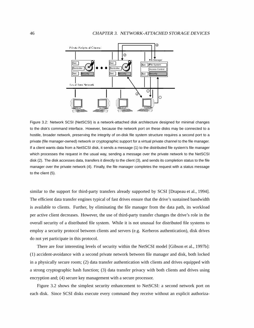
46 CHAPTER 3. NETWORK-ATTACHED STORAGE DEVICES
Net
Cm
ontroller
Net Sn
ecurity
No
et
No
et Sn
ecurity
Access Control
Fp
ile System
Fp
ile Manager Net
Cm
ontroller
Net Sn
ecurity
qsr�tBu3vWwyxzqsxWr�ty{�|�xWr�vW}�~�|�vW����xW}
�����WvW}3��r�xWvz��xWwy����r��
�/�Oc l!�O� �'�/�Q�Oc �����Q�Q�O�7hW���O�����Q�
�����/�O�D�]�O�/�!�]�Q� `3���O�
�
� � �
�
Figure 3.2: Network SCSI (NetSCSI) is a network-attached disk architecture designed for minimal changes
to the disk’s command interface. However, because the network port on these disks may be connected to a
hostile, broader network, preserving the integrity of on-disk file system structure requires a second port to a
private (file manager-owned) network or cryptographic support for a virtual private channel to the file manager.
If a client wants data from a NetSCSI disk, it sends a message (1) to the distributed file system’s file manager
which processes the request in the usual way, sending a message over the private network to the NetSCSI
disk (2). The disk accesses data, transfers it directly to the client (3), and sends its completion status to the file
manager over the private network (4). Finally, the file manager completes the request with a status message
to the client (5).
similar to the support for third-party transfers already supported by SCSI [Drapeauet al., 1994].
Theefficient datatransfer engines typical of fastdrives ensure that the drive’s sustained bandwidth
is available to clients. Further, by eliminating the file manager from the data path, its workload
per active client decreases. However, theuse of third-party transfer changesthedrive’s role in the
overall security of a distributed file system. While it is not unusual for distributed file systemsto
employ a security protocol betweenclients and servers (e.g. Kerberos authentication), disk drives
do not yetparticipate in thisprotocol.
There are four interesting levels of security within the NetSCSI model [Gibsonet al., 1997b]:
(1) accident-avoidancewith a second private network between file manager and disk, both locked
in a physically secure room; (2) data transfer authentication with clientsand drives equippedwith
a strong cryptographic hashfunction; (3) datatransfer privacy with both clients and drives using
encryption and; (4) securekey managementwith asecureprocessor.
Figure 3.2 shows the simplest security enhancement to NetSCSI: a second network port on
each disk. SinceSCSI disks execute every command they receive without an explicit authoriza-

3.2. TWO NETWORK-ATTACHED STORAGE ARCHITECTURES 47
tion check, without a second port even well-meaning clients can generate erroneous commands
and accidentally damage partsof the file system. The drive’s second network port provides pro-
tection from accidents while allowing SCSI command interpretersto continuefollowing their nor-
mal execution model. This is the architecture employed in the High Performance StorageSys-
tem [WatsonandCoyne,1995]. Assuming that file manager and NetSCSI disks are locked in a
secure room,this mechanism is acceptable for thetrustednetwork security model of NFS.
Because file datastill travels over the potentially hostile general network, NetSCSI disks are
likely to demand greater security than simple accident avoidance. Cryptographic protocols can
strengthenthesecurity of NetSCSI. A strongcryptographichashfunction,suchasSHA [NIST, 1994],
computedat thedriveandat theclient would allow datatransfer authentication (i.e., thecorrect data
wasreceivedonly if thesender andreceivercompute thesamehash on thedata).
For someapplications, data transfer authentication is insufficient, and communication privacy
is required. To provideprivacy, aNetSCSI drivemustbeable to encrypt and decrypt data. NetSCSI
drivescanusecryptographic protocols to construct private virtual channelsover theuntrustednet-
work. However, sincekeys will bestoredin devices vulnerable to physical attack, theservers must
still bestoredin physically secureenvironments.
If NetSCSI disks are equippedwith secure coprocessors [YeeandTygar, 1995], then keys can
beprotected andall datacan beencrypted whenoutsidethesecure coprocessor, allowing thedisks
to beusedin avariety of physically openenvironments.
3.2.2 Network-Attached SecureDisks(NASD)
With network-attached securedisks, theconstraint of minimal changefrom theexisting SCSI inter-
face is relaxed. Instead, the focus is on selecting a command interface that reducesthe numberof
client-storageinteractions that mustberelayedthrough thefilemanager, offloadingmoreof thefile
manager’swork without integrating filesystempolicy into thedisk.
Common,data-intensiveoperations,such asreadsandwrites, gostraight to thedisk,while less-
common ones, including namespace andaccesscontrol manipulations, go to the file manager. As
opposedto NetSCSI, wherea significantpart of theprocessing for security is performedon thefile
manager, NASD drivesperform most of theprocessing to enforcethesecurity policy. Specifically,
thecryptographic functionsandtheenforcementof manager decisionsareimplemented atthedrive,
whilepolicy decisionsaremade in thefilemanager.
Authorization, in the form of a time-limited capability applicable to the file’s map and con-

48 CHAPTER 3. NETWORK-ATTACHED STORAGE DEVICES
tents, is provided by the file manager which still maintains control over storage access policy
[Gobioff, 1999]. In order to service an accessto a file, the logical accessmust be mapped onto
physical sectors. This mapping canbemaintainedby the file manager and can beprovided dynam-
ically as in DerivedVirtual Devices(DVD) [VanMeteretal., 1996]. It canalso bemaintained by
the drive. In this latter case,the filesystemauthors must surrender detailedcontrol over the layout
of the files they create. With the “mapping metadata” that controls the layout of files maintained
at thedrive, a NASD drive exports a namespaceof file-like objects. Files in thedirectory tree are
mappedonto NASD objectsby the file manager, but the block management and allocation with a
NASD object is theresponsibilit y of theNASD device.
In summary, bothNetSCSI and NASD allow direct datatransfer. However, NASD decomposes
moreof the file server’s function anddelegatespart of it to the storage device. This is attractive
becauseit reducesfile server load[Gibsonet al., 1997b] allowing higher scalability. It also allows
computation resourcesto scale nicely with capacity. The following section discusses the NASD
architectureand its properties in moredetail.
3.3 The NASD architecture
Like NetSCSI, Network-Attached Secure Disks (NASD) repartition file server function among
client, deviceand residual file server. However, NASD delegates more functions to the client and
device to minimize theamount of client-server interactions in the commoncase. NASD doesnot
advocatethat all functionsof thetraditional file serverneed to beor should bemigratedinto storage
devices.NASD devices do not dictate the semantics of thehighestlevels of distributed file system
function – global naming, accesscontrol, concurrency control, and cache coherence. Nevertheless,
NASD devices, asdiscussed in the next chapter, can provide mechanismsto support the efficient
implementation of thesehigh-level functions. High-level policy decisions such asaccesscontrol,
naming and quota management, are stil l reservedto theresidual file server, which is called thefile
manager.
It is the largemarket for mass-produced disksthat promises to makeNASDcost-effective. This
massproductionrequiresastandardinterfacethat mustbesimple,efficient, and flexible to support a
widerangeof file system semanticsacrossmultipletechnology generations. TheNASDarchitecture
can besummarizedin its four key attributes:1) direct transfer to clients;2) asynchronousoversight
by file managers; 3) secureinterfacessupportedby cryptography; and 4) theabstractionof variable-
length objects.

3.3. THE NASD ARCHITECTURE 49
�
��M�O�Q�����<� ���'�W �¡
�����/�O�D�]�O�/�!�]�Q� `3���O�� � �
�
NASD File Manager
Access Control
Network Interface
Network Protocol
Network Driver
O¢
bject Storage
Cm
ontroller
Network Sn
ecurity
Sn
ecurity
Figure 3.3: Network-attached secure disks (NASD) are designed to offload more of the file system’s simple
and performance-critical operations. For example, in one potential protocol a client, prior to reading a file,
requests access to that file from the file manager (1), which delivers a capability to the authorized client (2).
So equipped, the client may make repeated accesses to different regions of the file (3, 4) without contacting
the file manager again unless the file manager chooses to force reauthorization by revoking the capability (5).
3.3.1 Direct transfer
Dataaccessed by a filesystem client is transferred between NASD drive and client without indi-
rection (store-and-forward) througha file server machine. Because control of naming is more ap-
propriate to the higher-level file system, pathnames are not understood at the drive, and pathname
resolution is split between thefile managerand client. A single drive object canstore thecontents
of a client file, althoughmultiple objectsmaybe logically linkedby thefile systeminto oneclient
file. Suchaninterfaceprovidessupport for banksof striped files[HartmanandOusterhout, 1993] or
logically-contiguouschunksof complex files [deJongeet al., 1993]. In any case,themapping from
high-level pathnameto an object is performedinfrequently and theresults of this mapping cached
at theclient. Thisallows theclient to accessthedevice directly in thecommoncase.
As an example of a possible NASD accesssequence, consider a file read operation depicted in
Figure 3.3. Before issuing its first readof a file, theclient authenticates itself with the file manager
and requests accessto the file. If access is granted, the client receives the network location of
the NASD drive containing the object and a time-limited capability to accessthe object and for
establishingasecurecommunicationschannel with thedrive. Afterthispoint, theclient maydirectly
requestaccessto dataonNASD drives,using theappropriatecapabilit y [Gobioff, 1999].

50 CHAPTER 3. NETWORK-ATTACHED STORAGE DEVICES
3.3.2 Asynchronousoversight
Accesscontrol decisionsmadeby afile managermustbeenforcedby aNASD drive. Thisenforce-
ment impliesauthentication of thefile manager’s decisions. Theauthenticateddecision authorizes
particularoperationsonparticular groupingsof storage. Becausethisauthorization is asynchronous,
a NASD device may be required to record anaudit trail of operationsperformed,or to revokeau-
thorization at thefile manager’s discretion. For a small number of popular authentication systems,
Kerberos [NeumanandTs’o, 1994] for example, NASD drives could be built to directly partici-
pate, synchronously receiving a client identity and rights in an authenticated message from a file
manager during its accesscontrol processing. DerivedVirtual Devices usethis approach, which is
simplified by theavailability of authenticatedRPC packages, alsoused by filesystemssuch asAFS
[Satyanarayanan, 1990].
An alternative that does not depend on the local environment’s authentication system and that
doesnot depend on thesynchronousgranting of rightsby the file manager, is to employ capabili-
tiessimilar to theICAP [Gong, 1989] or Amoeba[Mullender etal., 1990] distributedenvironments.
Capabiliti esare transportedto the device via a client but areonly computable/mutable by file man-
ager and NASD drive. Filesystempolicy decisions, such aswhatoperations a particular client can
perform on a particular set of stored data, are encodedinto capabilit iesby the file manager. These
capabilitiesaregiven by thefilemanager to clients. A client presentsthesecapabiliti esto theNASD
drives, whoenforcetheaccesscontrol policy by decrypting and examiningthecontentsof thesealed
capability, without synchronous recourseto thefilemanager.
The problem of ensuring security in a NASD-based storage system is the topic of a recent
dissertation [Gobioff, 1999]. The key observation here is that ensuring security in a NASD system
doesnot require a central entity that is involved in thecritical pathof data transfer. File managers
are contacted only infrequently and do not interfere with common-casedata transfers. Moreover,
the NASD device doesnot dictatehow accesscontrol is enforced. It providesa mechanism for
enforcing authorization which canbeusedby differenttypesof filesystems.
Efficient, secure communications defeats message replay attacks by uniquely timestamping
messageswith loosely synchronizedclocks andenforcing uniqueness of all received timestamps
within askew threshold of each node’scurrenttime. Although all that is neededin aNASD drive is
a readable, high-resolution, monotonically increasing counter, thereare furtheradvantagesto using
a clock whose rate is controlled by a network time protocol such asNTP [Mills, 1988]. Such a
clock, for example, canbe exploited to develop efficient timestampordering protocols for concur-

3.3. THE NASD ARCHITECTURE 51
rency control. Suchaprotocol is describedin Chapter4.
3.3.3 Object-basedinterface
Theset of storageunitsaccessible to aclient astheresult of anasynchronousaccesscontrol decision
mustbe namedand navigated by client andNASD. Becausea NASD drive must enforce access
control decisions, a file manager should describe a client’s accessrights in a relatively compact
fashion. While it is possible for the file manager to issue one capability granting a client access
to a block or block range, this approach results in a large number of capabili ties. Furthermore, it
requiresa new capability to be issuedevery timeanew block is allocated on aNASD device.
It is therefore advantageous for thecapabilit y to refer to compact names that allow a client to
simplif y its view of accessiblestorageto avariable length set of bytes,possibly directly correspond-
ing to a file. Such namesmaybetemporary. For example, Derived Virtual Devices(DVD) use the
communicationsport identifierestablished by thefilemanager’sdecision to grant access to agroup
of storage units [VanMeteret al., 1996]. In the prototype interface, a NASD drive partitions its
allocated storageinto containerswhich we call objects.
TheNASD object interfaceenhancestheabilit y of storagedevices to managethemselves. Pre-
vious research hasshown that storagesubsystems canexploit detailed knowledgeof their own re-
sourcesto optimizeon-disk block layout, prefetching and read-aheadstrategiesand cachemanage-
ment[English andStephanov, 1992, Chao etal., 1992, deJongeetal., 1993, Pattersonet al., 1995,
Golding etal., 1995].
Magnetic disksarefixed-sizedblockdevices.Traditionally, filesystemsareresponsible for man-
aging theactual blocks of the disks under their control. Using notionsof thedisk drive’s physical
parameters and geometry, filesystems maintain information about which blocks are in-use, how
blocks are grouped together into logical objects, and how theseobjects are distributed acrossthe
device [McKusick etal., 1984, McVoy andKleiman, 1991].
CurrentSCSI disks offer virtual or logical fixed-sized blocks namedin a linear addressspace.
Moderndisksalready transparently remapstoragesectors to hidedefective mediaand thevariation
in track densities across the disk. By locating blocks with sequential addresses at the location
closestin positioning time(adjacentwherepossible),SCSI supportsthelocality-basedoptimizations
being computedby the filesystems’obsolete disk model. More advancedSCSI devicesexploit this
virtual interface to transparently implement RAID, data compression, dynamic block remapping,
and representation-migration [Pattersonet al., 1988, Wilkesetal., 1996, Hollandetal., 1994].
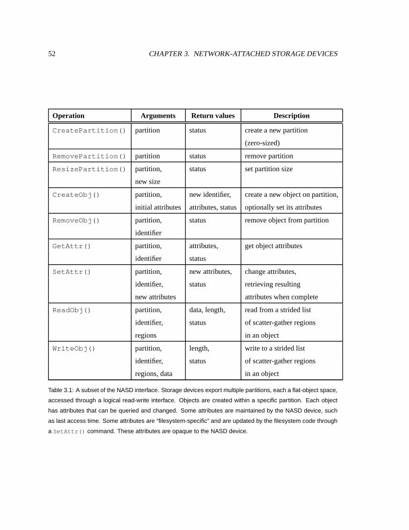
52 CHAPTER 3. NETWORK-ATTACHED STORAGE DEVICES
Operation Ar guments Return values Descripti on
CreatePartition() partition status createa new partition
(zero-sized)
RemovePartition() partition status removepartition
ResizePartition() partition, status setpartitionsize
new size
CreateObj() partition, new identifier, createa new objecton partition,
initial attributes attributes,status optionally set its attributes
RemoveObj() partition, status removeobjectfrompartition
identifier
GetAttr() partition, attributes, get objectattributes
identifier status
SetAttr() partition, new attributes, changeattributes,
identifier, status retrieving resulting
new attributes attributeswhencomplete
ReadObj() partition, data, length, read from astridedlist
identifier, status of scatter-gatherregions
regions in an object
WriteObj() partition, length, write to astrided list
identifier, status of scatter-gatherregions
regions, data in an object
Table 3.1: A subset of the NASD interface. Storage devices export multiple partitions, each a flat-object space,
accessed through a logical read-write interface. Objects are created within a specific partition. Each object
has attributes that can be queried and changed. Some attributes are maintained by the NASD device, such
as last access time. Some attributes are “filesystem-specific” and are updated by the filesystem code through
a SetAttr() command. These attributes are opaque to the NASD device.

3.3. THE NASD ARCHITECTURE 53
£¥¤'¤'¦k§�§¨¤F©«ªM¬®7©M¯±°�¦'²§�³®©«ª´�µ §�¬ µ ¬®¬Q�³®¶�·«¬®¦�¸¹©MºM³®»7¼½¬®³Q¸¾¦´�µ §.¬sº µ ¬ µ ¸¹©MºM³Q»�¼½¬Q³®¸¹¦
¿ �¦ µ ¬Q¦�¬®³®¸¹¦À £ÂÁ�ÃÄ©«¶WÅ&¦'¤'¬ µ ¬Q¬®�³Q¶�·M¬®¦k§ Ã¥¦�°«³®¤'¦'Æ�º«¦'ªM¦'º½©M¶FÅ&¦'¤'¬µ ¬®¬Q�³®¶�·«¬®¦k§
Ã¥¦W°M³®¤'¦'Æ�©«Ç µ!È ·M¦�¯Q¦k§.¼É§.¬Q¦'¸§�ÇM¦'¤'³®¤ µ ¬Q¬®�³Q¶�·M¬®¦k§
Ê ¶WÅ&¦'¤'¬±¯Q©MËM³®¤ µ ¯-§.³QÌ'¦Í<Í<Í<ͦ Í Ë Í ©�ÎϪM¦',ÐW¸¹©MºM¦�¶M³Q¬&§�Ц'¬Q¤«Ð Í<Í<Í
Figure 3.4: Structure of a NASD object’s attributes. Some attributes are maintained by the device such as
create time, object size, and last data modify time. In addition to NASD maintained attributes, each object has
an access control version variable and a large filesystem-specific attribute space (256 bytes in our prototype)
which is used by the filesystem for its own purposes.
The NASD interface abandons the notion that file managers understand and directly control
storage layout. Instead, NASD drives store variable-length, logical byte streamscalled objects.
Filesystemswanting to allocatestorage for a new file request oneor moreobjects to hold thefile’s
data. Read and write operations apply to a byte region (or multiple regions) within anobject. The
layout of anobjecton thephysical media is determinedby theNASD drive. To exploit thelocality
decisions made by a file manager, sequential addresses in NASD objects should be allocated on
the media to achieve fastsequential access. For inter-object clustering,NASD breaks from SCSI’s
global addressspace and adopts a linked list of objects where proximity in the list encourages
proximity on themedia,similar to theLogicalDisk model [deJongeet al., 1993].
In addition to being data stores, NASD objectsmaintain associated metadata, calledobject at-
tributes. Figure 3.4 depictsan exampleof NASD objectattributes. Someattributes such as create
time, the lasttime thedata was written, or the lasttime the attributeswere modified aremaintained
by the device and cannot be directly manipulated by the external systems. Theseattributesare
updated indirectly when the object is created, when the object’s data is written to, or when any
attributesare modified respectively. In addition to theNASD maintained attributes,li sted fully in
[Gibsonetal., 1997a],each NASD object hasalarge“filesystemspecific” attributespace(256 bytes
in our prototype). Theseattributesareopaqueto theNASD devicewhichtreatsthemasabytestring.
These areupdated andmanipulated by the filesystem for its own purposes. For instance,a UNIX
like filesystemmay use theseattributesto storethemodebitsor theownerand group identifiers.

54 CHAPTER 3. NETWORK-ATTACHED STORAGE DEVICES
Theimportantsubsetof theNASD interface is summarizedin Table 3.1; a more complete and
detailed descriptionof theNASD interfaceisprovidedin Gibson etal. [Gibsonet al., 1997a].
3.4 The Cheopsstorageservice
A filesystemusing NASD devicesallowsclientstomakedirect readandwrite accessesto thestorage
devices.Simulation studiesreportedin [Gibson etal., 1997b] demonstratedthat an NFS file server
can support anorder of magnitude more clients if NASD baseddevicesare usedin lieu of server-
attacheddevices. AFSfile serverswereshown to support three timesmoreclients.
AlthoughNFSand AFSwerelater portedto useNASD to validate theNASDinterfaceand gain
further experience, scalability experiments with largeclient populations were not carried out. The
design of AFS and NFSover NASD is reportedin [Gibsonet al., 1998]. In their NASD ports,both
NFS andAFSover NASD mappeda single file or directory in thedirectory structure onto a single
NASD object on asingledevice. Largefile transfer could not benefit fromparallel striped transfers.
Furthermore,RAID acrossdeviceswasnot supported.
To exploit the high bandwidth possible in a NASD storage architecture, theclient-resident por-
tion of a distributed filesystem needs to make large, parallel data requestsacrossmultiple NASD
drivesand to minimize copying, preferably bypassing operating system file caches. Cheops is a
storage service that can be layered over NASD devicesto accomplish this function. In particular,
Cheopswasdesignedto providethis function transparently to higher level filesystems.
3.4.1 Cheopsdesign overview
Cheops implements storage striping and RAID functions but not file naming and other directory
services. This maintains the traditional “division of concerns” betweenfilesystemsand storage
subsystems,such as RAID arrays. Cheops performs the function of a disk array controller in a
traditionalsystem. Oneof thedesigngoalsof Cheopswasto scaleto avery largenumbersof nodes.
Another goal was for Cheops to export a NASD interface, so that it can be transparently layered
below filesystemsportedto NASD.
Cheopsallows higher-level file systems to managea single logical object that is servedby the
Cheops storage management system[Gibsonet al., 1998]. Cheopsexports the illusion of a single
virtual NASD devicewith theaggregatecapacity of theunderlying physical NASD devices. To the
clients and file managers, thereappears to be a single NASD device. This device is accessed via
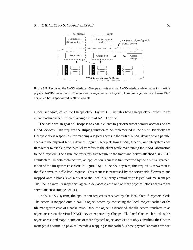
3.4. THE CHEOPSSTORAGE SERVICE 55
Controller
Controller
Controller
single virtual, configurableFile manager
(Directory Server)Client File System
File manager Client
Module
Cheops clerk Cheops clerkmanagerCheops
NASD devices managed by Cheops
NASD device
Figure 3.5: Recursing the NASD interface. Cheops exports a virtual NASD interface while managing multiple
physical NASDs underneath. Cheops can be regarded as a logical volume manager and a software RAID
controller that is specialized to NASD objects.
a local surrogate, called the Cheops clerk. Figure 3.5 il lustrateshow Cheops clerks export to the
client machines theillusion of a singlevirtual NASD device.
Thebasic design goal of Cheops is to enable clients to perform direct parallel accesses on the
NASD devices. This requiresthe striping function to be implemented in the client. Precisely, the
Cheopsclerk is responsible for mapping a logical accessto thevirtualNASD deviceonto aparallel
access to the physical NASD devices. Figure 3.6depicts how NASD, Cheops, and filesystemcode
fit together to enable direct parallel transfers to theclient while maintaining the NASD abstraction
to thefilesystem. Thefigurecontrasts thisarchitectureto thetraditional server-attached disk (SAD)
architecture. In both architectures,anapplication request is first receivedby theclient’s represen-
tation of the filesystem(file clerk in Figure3.6). In theSAD system, this requestis forwarded to
the file server asa file-level request. This request is processed by the server-side filesystem and
mapped onto a block-level request to the local disk array controller or logical volume manager.
The RAID controller maps this logical block access onto oneor more physical block accessto the
server-attached storagedevices.
In the NASD system, the application request is received by the local client filesystem clerk.
The access is mapped onto a NASD object accessby contacting the local “object cache” or the
file manager in caseof a cachemiss. Once the object is identified, thefile access translatesto an
object accesson the virtual NASD deviceexported by Cheops. The local Cheopsclerk takesthis
object accessand mapsit ontooneor morephysicalobject accessespossibly consulting theCheops
manager if a virtual to physical metadata mapping is not cached. Thesephysical accessesaresent

56 CHAPTER 3. NETWORK-ATTACHED STORAGE DEVICES
NASD NASD NASD NASD
Cheops clerk Cheops clerkStorage manager
(RAID, LVM)
SCSI SCSI
File manager File Clerk File ClerkFile system server
File system client
Cheops manager
(ticket server)
(ticket server)
Controller
Controller
Controller
Controller
Controller
Controller
Client−app
Block interface
Client−app Client−app
File interface (Network) File interface
Object interfaceBlock interface
File server
RAID controller
Client Client
(Network)Object interface
(b) NASD architecture(a) Server−attached disk architecture
Client
Figure 3.6: Function decomposition in NASD compared to traditional file server based storage. At each client,
a file clerk performs file caching and namespace mapping between high-level filenames and virtual storage
objects. The storage clerk on the client receives logical accesses to a virtual storage object space, and maps
the accesses onto physical accesses to the NASD objects. Parallel transfers are then carried out from multiple
NASDs into the storage clerk.
out on the network. The Cheops clerk and managers at this layer implement the function of the
RAID controller in theSAD system.
Cheopsmanagersmanagethemetadatamapsand initiatemanagement taskssuchasreconstruc-
tion, backup and migration. Upon receipt of a lookup request from a clerk, the Cheops manager
returnsthemapping of thehigherlevel object ontoasetof underlying NASD objectsand theappro-
priate capabilit y list. This mapping and capabilit y list is used by the clerk to perform theaccessed
to the NASD devices. Cheops-exportedobjects have attributesasrequiredby theNASD interface.
Theseattributescan beembeddedin oneof thephysical NASD objectsor in aseparateobject. The
first solution doesnot requireallocating additional physical NASD objectsbut can disrupt thealign-
ment of client accesses. Thesecondsolution allocatesoneNASD object per partition or per group
of objects to store the attributesof thevirtual objects in that partition. This is more desirable since
it doesnot disrupt the alignment of client accessesat the expense of slightly more implementation
complexity.
This layered approachdoesnot adversely affect the overall file manager’s control because it
is already largely asynchronous. For example, the file manager revokesa high-level capabilit y
in a physical NASD by updating the attributes of the object on the NASD device. Because the

3.4. THE CHEOPSSTORAGE SERVICE 57
device comparesattributesencoded in thecapabilit y with theseon thedeviceduring every access,
modify ing the attributes amounts to revoking the capability. This is implemented in Cheops as
follows. The file manager invokes a SetAttr() to the virtual NASD device (through the local
clerk) to modify the access version number attribute. This request is relayed by the local clerk
to theCheops manager. The Cheops manager revokes accessto eachphysical object by updating
their attributes before acknowledging a response to the file server. This is implemented by the
Cheopsmanagerasfollows. Recall that theclerks at many clientsmayhave cached the“vi rtual to
physical” mapping and thecapabiliti esthatallow themto perform accessto theunderlyingphysical
object. Themanager candisallow these clients from accessing storage immediately by modify ing
the attributes of the underlying physical objects. Thus, to revoke a capabili ty, the file manager
sends a SetAttr() to the local clerk, the surrogate of all virtual objects managed by Cheops.
This request is forwardedby theclerk to theCheopsmanager. The manager in turnssendsSet-
Attr() commandsto theunderlying physicalNASD objectstomodify their attributes,invalidating
all outstanding physical capabili ties.
3.4.2 Layout protocols
Cheopsclerks cachethelayout mapsfor recently accessed virtual objects locally. The layout map
describes how a virtual object is mappedonto physical NASD objects,and provides capabilit iesto
enable accessto eachphysical NASD.Furthermore,thelayout mapsdescribehow theobject should
be readand written. For example, a map may specify that an object is striped acrossfour NASD
objectswith astripeunit sizeof 64KB according to aRAID level 0 layout.
A Cheops clerk usesthe layout map to readand write the objects. In the current prototype
implementation, theCheops clerk as well asthemanager contain codethat allow themto access a
statically defined setof possible layoutsand their associatedaccessalgorithms. Chapter5 describes
a framework that enablesthe Cheopsclerk to bedynamically extendedto perform accesses to new
architecturesintroducedby aCheopsmanager.
Thelayout cachedby Cheops clerks may changeas a result of a failure or a management oper-
ation. Disk failuresrequire theuseof different access protocols to readandwrite a virtual object.
Furthermore, the layout map may change becauseof a storage migration initiated by a manager.
To maintain the coherenceof maps, layouts mapsare consideredvalid for a limitedperiod of time.
After that period, calledthe lease period, passes, the layout map is consideredinvalid and mustbe
refreshed by theclerk. The clerk refreshesthemapby contacting a storagemanager to find out if

58 CHAPTER 3. NETWORK-ATTACHED STORAGE DEVICES
themaphaschanged.
When a Cheops manager desires to change a layout map, for examplebecause storage has
migrated to a new device, it sends explicit messages to the clients to invalidate their cachedmaps.
Messagesmust be also sent to thedevices to revokeaccess,by invalidating thecapabilit iescached
at the clients. Becausethe layout maps expire after a certain period, crashed clients and network
partitionsare handled easily in the sameway. If any client doesnot acknowledgethe invalidation,
the manager waits until the leaseexpiresandthenperformsits layout change. Fault recovery and
concurrency control in Cheopsdeservesa deeper discussion, which is thesubject of the following
chapter.
3.4.3 Storageaccessprotocols
Cheopsclerkscontain statically linked code that allows them to perform read andwriteaccesses to
several RAID architectures,namely RAID levels0, 1 and5. In Cheops, it is possible for multiple
storageaccessfrommanyclientstobeongoing concurrently at thesametime. Furthermore,adevice
or host failuremayoccur in the middle of theexecution of a storage access. Correctnessmustbe
ensuredin themidstof thisconcurrency and in thecaseof untimely failures.The followingchapter
addressesthisconcurrency control and recovery problem. For therestof thischapter, wewil l focus
only on normalcaseperformance.
3.4.4 Implementation
TheCheopsclerk is implemented asa library which canbelinkedin with user-level filesystemsand
applications. It usesmultiple worker threadsfrom a statically sizedthread pool to initiate multiple
parallel RPCs to several NASD devices. Data returned by the NASD devicesis copied only once
from the communication transport’s buffers to the application space. The Cheops clerk does not
induce an extra copy. Instead, it deposits datareturnedby each device directly in the application
buffer at theproperoffset.
Cheopsclerksmaintain a least-recently-usedcacheof virtual-to-physical mappings. Theclerks
also maintain a cache of NASD device tables. These tables map a NASD device id onto an IP
addressand a port and a communication handle if a channel is still open between the clerk and
the device. Cheops used initially DCE RPC over UDP/IP as the communication transport. A later
implementation used a lightweight RPCpackagewith betterperformance[Gibson etal., 1999].
Cheopsbuilds on several earlier prototypesin network filesystems and in striping storage sys-

3.4. THE CHEOPSSTORAGE SERVICE 59
ÑQÒBÓ ÒÕÔ Ô ÖÕÔQ×?ØÙ,ÚBÚ ÖÕÛOÛ7Ü/ÝyÞyß Ó ÝyÔà,ÒBá�ÖBÛ âyÒ Ú ÖÜ/ÝyÞyÛ ã Û ß ÖÕÞ ÚÕäà,ÖBß®ÑDÓ Ýyß Ý Ú ÝyÔà,ÖBßQå,ÒBÓ æyç!ÒBÓ Ö
Ñ?ÒÕÓ ÒBÔ Ô ÖBÔQ×?ØÜ/èyÖBÝyâyÛà�ÖÕßQÑ?Ó Ýyß Ý Ú ÝyÔ
Ù âyâyÔ ã Ú ÒBß ã ÝyÞ
é²êyë ìWíïîBðWî�ñ/ì<ò
ó ë ê®ìBð/ô
õ ôyöQò.î.ñ/ìWíïîBðWî�ñ/ìBòÜ/èyÖBÝyâyÛ7÷�ÒÕÞyÒBøyÖÕÓÜ/ÝyÞ ÚBù Ó Ó ÖÕÞ ÚÕä Ü/ÝyÞyß Ó ÝyÔ÷�ÒBâyâyã Þyøú/ÖÕæ ù ÞyæyÒBÞ ÚÕäà,ÖBß®ÑDÓ Ýyß Ý Ú ÝyÔà,ÖBßQå,ÒBÓ æyç!ÒBÓ Ö
ûýü®þ.ü®ÿ������®þ�����®ü��� ��� � �
����� ���������.þ�� � ��� ������� ��� �����������������
à,ÖBßQå,ÒÕÓ æyç,ÒBÓ Ö
÷�Ñ"!
õ$# ê ô&%�'
(�)+* � � �-,/.�0�,21 3�4+,21 524+,21 624+,21 7�8
(�)+* � � �-,21 3 (�)+* � � �-,21 6(9)+* � � �-,21 5 (9)+* � � �-,21 7(�)+* � � �-,
Figure 3.7: A NASD-optimized parallel filesystem. NASD PFS is Cheops with a simple filesystem layer on top
of it. This filesystem layer performs data and name caching. NASD PFS is used in conjunction with MPI for
parallel applications in a cluster of workstations. The filesystem manages objects which are not locally backed
by data. Instead, they are backed by a storage manager, Cheops, which redirects clients to the underlying
component NASD objects. Our parallel filesystem extends a simple Unix filesystem interface with the SIO
low-level interface [Corbett et al., 1996] and inherits a name service, directory hierarchy, and access controls
from the filesystem.
tems [Cao etal., 1994, Cabreraand Long, 1991, Leeand Thekkath, 1996]. In its RAID level 0 im-
plementation, it serves to demonstrate that the NASD interfacecan be effectively and efficiently
virtualized, so thatfilesystemsdo not have to know about theunderlying storagemanagement that
is ongoing insideCheops.
A parallel file systemwas usedto demonstrate thebandwidth scaling advantages of NASD ar-
rays,asdepicted in Figure3.7.Such afile system wasusedbecausehighbandwidthapplicationsare
oftenparallel applications. MPICH version 2 [Forum,1995] for parallel program communications
wasusedto implementa simple parallel file system, NASD PFS. NASD PFS is implemented in a
library which in turns links to theCheopsclerk library.
BecausetheNASD prototypeused DCE onUDPfor datatransfer, theCheopsclerkusesDCEas
well. Parallel cluster applicationsoftenemploy low-latency systemareanetworks,which, by offer-
ing network adapter support for protocol processing, can dramatically shortenthecodeoverheadfor
bulk datatransfer. Our prototypedidnothavesuchon-boardprotocolprocessing [Gibson etal., 1998].
Nevertheless, the application described in this Chapter are so data-intensive that they can accom-
modatethecomputational overheadof DCE RPC overUDP and still exhibit significantspeed-ups.

60 CHAPTER 3. NETWORK-ATTACHED STORAGE DEVICES
3.5 Scalable bandwidth on Cheops-NASD
To evaluatethescalability of NASD/Cheops, a basic prototype implementation of Cheops to work
with the prototype NASD device. The scalability of NASD/Cheops was compared to that of a
traditionalNFSfile serverwith disksdirectly attached to theserver. Thehardwareconfigurationsof
both systemswerecarefully constructed to provide a fair comparison.
Bothsynthetic benchmarks(read/write), aswell asI/O intensiveapplicationssuchassearchand
datamining weredesigned, implemented and evaluatedonSAD and NASD architectures.
3.5.1 Evaluation envir onment
Our experimental testbed consists of clients, file managers and NASD drives connected by a net-
work. The NASD prototype is described in [Gibsonetal., 1998] and implements its own internal
object access,cache,and disk space management modules(a total of 16,000 linesof code) and in-
teractsminimally with Digital UNIX. For communications,theprototypeusesDCE RPC1.0.3over
UDP/IP.
Thescalability of NASD/Cheopswascomparedto thatof atraditional NFSfile serverwith disks
directly attached to the server. The hardware for the NASD/Cheops system wascomposed of the
following:
: NASDs: A NASD consistsof SCSI disks (SeagateMedallist ST52160) attached to an old
workstation. Two SCSI disks, with anaveragetransfer rateof 3.5-4MB/seceach, were used
as the magnetic storagemedia. Objectdata is striped across both disks yielding an effective
sequential transfer rate of up to 7.5 MB/sec. The workstation is a DEC Alpha 3000/400
(133MHz, 64 MB, Digital UNIX 3.2g). TheSCSI disks areattached to theworkstation via
two 5 MB/s SCSI busses. Theperformanceof this five year old machine is similar to what
is available in high-end drives today and to what is predicted to be available in commodity
drive controllers soon. We use two physical drives managedby a softwarestriping driver to
approximatethe10 MB/s rateswe expectfrommoremodern drives.
: Clients: Digital AlphaStation 255 machines(233Mhz, 128MB, Digital UNIX 3.2g-3) were
usedasclients.
: File manager: OneAlpha3000/500(150 MHz, 128MB, Digital UNIX 3.2g-3) wasused asa
file manager.

3.5. SCALA BLE BANDWIDTH ON CHEOPS-NASD 61
: Network: The clients andthe NASDs were connected by a 155 Mb/s OC-3 ATM network
(Digital Gigaswitch/ATM).
Thetraditional NFSserverconfiguration is referred to asserver-attached-disk (SAD) configura-
tion. Themuchmoreeffectivehardwareused for theSAD system wascomposedof the following:
: File Server: A digital AlphaStation500/500 wasused asa“traditionalfile server” (500 MHz,
256MB, Digital UNIX 4.0b). Thefileservermachinewasconnected via two OC3ATM links
to aDigital Gigaswitch/ATM, with half of theclientsusing each link.
: Storagedevices: EightSCSI disks (SeagateST34501W, 13.5MB/s) were attachedto thefile
server workstation via two 40MB/sWideUltraSCSI busses, sothat theperipheral SCSI links
into theworkstationcandeliver thebandwidth of thedisks.
: Clients: As in theNASD case, AlphaStation 255 machineswereusedasclients.
: Network: As in theNASD case, the clients and the server were connectedby a 155 Mb/s an
ATM network (Digital Gigaswitch/ATM).
3.5.2 Raw bandwidth scaling
The parallel application employed in this demonstration is a datamining application that discovers
association rules in sales transactions [Agrawal and Schafer, 1996] with synthetic datagenerated
by a benchmarking tool. This application “discovers” rules of the form “ if a customer purchases
item A and B, thenthey are also likely to purchase item X” to beusedfor storelayout or inventory
decisions. It doesthis in several full scansover thedata,first determining theitems thatoccur most
oftenin thetransactions (the1-itemsets) and thenusing this information to generate pairs of items
thatoccur often(2-itemsets)and largergroupings(k-itemsets).
Our parallel implementation avoids split ting recordsover 2 MB boundariesand usesa simple
round-robin schemeto assign 2 MB chunks to clients. Each clientis implemented as four producer
threadsand a single consumer. Producer threadsreaddata in 512 KB requests(which is the stripe
unit for Cheops objects in this configuration) and the consumer thread performsthe frequent sets
computation, maintaining a set of itemset counts that are combinedat a single master client. This
threading maximizesoverlapping and storageutili zation.
Figure 3.8shows the bandwidth scalability of the most I/O bound of thephases (thegeneration
of 1-itemsets) processing a 300 MB sales transaction file. A single NASD provides 6.2 MB/s per

62 CHAPTER 3. NETWORK-ATTACHED STORAGE DEVICES
0;
2<
4=
6>
8?
Number of Disks
0;
.0
10
2<
0
3@
0
4=
0
5A
0
App
licat
ion
Thr
ough
put (
MB
/s)
CB
heops/NASD NC
FS NC
FS-parallel
Figure 3.8: Scaling of a parallel data mining application. The aggregate bandwidth computing frequent sets
from 300 MB of sales transactions is shown. The NASD line shows the bandwidth of N clients reading from
a single NASD PFS file striped across N NASD drives and scales linearly to 45 MB/s. All NFS configurations
show the maximum achievable bandwidth with the given number of disks, each twice as fast as a NASD,
and up to 10 clients spread over two OC-3 ATM links. The comparable NFS line shows the performance of
all the clients reading from a single file striped across N disks on the server and bottlenecks near 20 MB/s.
This configuration causes poor read-ahead performance inside the NFS server, so we add the NFS-parallel
line where each client reads from a replica of the file on an independent disk through the one server. This
configuration performs better than the single file case, but only raises the maximum bandwidth from NFS to
22.5 MB/s.
NASD drive andour array scales linearly up to 45 MB/s with 8 NASD drives. In comparison, we
alsoshow thebandwidth achievedwhen NASD PFS fetchesfrom a single higher-performance tra-
ditional NFSfile instead of aCheopsNASD object. TheNFSfile serveris an AlphaStation500/500
(500 MHz, 256 MB, Digital UNIX 4.0b) with two OC-3 ATM links (half theclients communicate
over each link), and eight Seagate ST34501W Cheetah disks (13.5 MB/s) attached over two 40
MB/s Wide UltraSCSI busses. Using optimal code, this machine can internally readasmuch as
54.1 MB/s from thesedisks through the raw disk interface, doing nothing with this data.
Thegraphof Figure3.8showstwo application throughput linesfor this server. Thelinemarked
NFS-parallel showstheperformanceof eachclientreadingfrom anindividual file onanindependent
disk on theoneNFS file server and achievesperformanceup to 22.5 MB/s. The results show that
an NFS server (with 35+ MB/s of network bandwidth, 54 MB/s of disk bandwidth anda perfect
sequential accesspattern oneachdisk) losesmuchof itspotential performanceto CPU andinterface
limits. In comparison, each NASD is able to achieve 6.2 MB/s of the raw 7.5 MB/s available
from its underlying dual Medalli sts. Finally, the line markedNFSis actually themostcomparable
configuration to the NASD experiment. It shows the bandwidth when all clientsreadfrom a single
NFS file striped across N disks. This configuration, at 20.2 MB/s, is slower than NFS-parallel

3.6. OTHER SCALA BLE STORAGE ARCHITECTURES 63
becauseitsprefetching heuristics fail in thepresenceof multiple requeststreamsto asingle file.
In summary, NASD PFS on Cheops delivers nearly all of the bandwidth of theNASD drives,
while thesame application using a powerful NFS server fails to deliver half theperformanceof the
underlying Cheetah drives. The differencein performance is expected to widen with larger sizes,
as Cheops continuesto exploit the available network bandwidth for aggregateparallel transfers.
Server-basedfilesystemsarelimited,ontheotherhand,by theperformanceof theservermachine. In
very largesystems,multiplefileserversmust beused. This complicatesadministration. Cheopscan
deliver a single virtual storageabstraction from a largecollection of storagedevices. Nevertheless,
largesystemsbring challengesfor both architectures. Theupcoming chapterdiscusseshow ashared
storagearray, li keCheops,canensurescalable concurrency control and fault-tolerance in very large
systems.
3.6 Other scalablestorage architectures
Scalable storage is not a new goal. Several storage systemshave been designed with the goal of
delivering high-bandwidth to clients. Several othershave focussedon scaling to largesizes. This
sectionbriefly reviewsthealternativearchitecturesthathavebeenproposedin theliteratureandhow
they compareto Cheops/NASD.
Previous storage systemsreviewedin this section are organizedinto threecategories. The first
corresponds to systems which removed thefile server machine from thedatatransfer path, thereby
decoupling control from data transfer. Thesecond corresponds to systems that stripeddata across
multiple storage nodes to achieve high I/O data rates,while the third corresponds to systems that
distributed the storage management and access functions to the nodes while tolerating the node
failures.
3.6.1 Decoupling contr ol fr om data tr ansfer
The availabili ty of high-bandwidth disk arrays have recently highlightedthe fileserver as the chief
bottleneck in storageaccess. To eliminatethe file server from thedatapath, several systemspro-
posed decoupling control messaging in filesystems from actual data transfer. Examples include
HPSS [WatsonandCoyne,1995] and RAID II [Drapeau etal., 1994] which focussed on moving
thefile server machineout of thedatatransfer path. Thesesystemsstill relied on synchronousover-
sight of thefile server on each access operation. However, data is transferreddirectly from storage

64 CHAPTER 3. NETWORK-ATTACHED STORAGE DEVICES
to theclient network without being copiedthroughthefile server machine.
RAID II
After building the initial redundantdisk array prototype in 1989, the RAID group at U.C. Berke-
ley discovered that parallel transfers from a disk array can achieve higher bandwidth than can be
delivered by the memory system of the host workstation. The second RAID prototype, RAID
II [Drapeau etal., 1994], wasdesignedto addressthisbottleneckanddeliver asmuchaspossibleof
thearray’sbandwidth to fileserverclients.
A custom-built crossbar memory system was used to connect disks directly to a high-speed
network to which clientsareattached. Thisallowedparallel transfers from thedisksto theclients to
use thehigh-speed crossbarand network without going through the server’s memory. TheRAID II
prototypewasusedby a log-structured filesystemto deliverhigh read and write bandwidthsto data-
intensive applications. The RAID II system was shown to deliver up to 31 megabytespersecond
for sequential readoperations,and20 megabytes for largerandom accesses.
MassStorageReferenceModel
TheMassStorageSystemReferenceModel, an early architecture for hierarchical storage subsys-
tems, hasadvocatedtheseparation of control anddatapathsfor almostadecade[Mil ler88,IEEE94].
TheMassStorageSystemReferenceModelwasimplementedin theHigh PerformanceStorageSys-
tem (HPSS) [WatsonandCoyne, 1995] and augmented with socket-level striping of file transfers
over themultiple network interfacesfound on mainframesandsupercomputers.
HPSSpreserved thefixedblock interface to storageand continuesto rely on synchronousover-
sight of commandsby thefile manager. It constitutesa first stepin totally removing the file server
from thedatapath. Cheops over NASD builds on this idea of decoupling control from data trans-
fers. It more aggressively avoidsthefile manager, however, by allowing clientsto cache long-term
mappingswhich canbe usedto directly translatea high-level file access to a storage device access
without recoursethefile manager.
3.6.2 Network-striping
To allow client applications high-bandwidth access to storage, several storage systemssuch as
Swif t [Cabreraand Long, 1991], Zebra[Hartman and Ousterhout, 1993] andTiger [Bolosky etal., 1996]
introducedtheideaof striping acrossmultiple storageserversacrossanetwork.

3.6. OTHER SCALA BLE STORAGE ARCHITECTURES 65
Swif t
To obtain cost-effectivescalablebandwidth ona local areanetwork, datamustbestripedacrossthe
network and acrossmultiple servers. Swift [Cabreraand Long, 1991] is an early striping storage
system thatpartitionedclient dataacrossmultiplestorageserversto providehigh aggregateI/O rates
to its clients. A “storage manager” decided file layout, stripe unit sizeand reliabili ty mechanism.
Usersprovidedpreallocation info suchassize, reliability level, dataraterequirements.
Cheopsissimilar to Swift in its architecture. Cheopsdiffers from Swif t in that it is designedto
work with theNASD object interface. Furthermore,Swift li ke Zebra,did not focuson theproblem
of ensuringhighly concurrent writeaccessto sharedRAID storage. Theprotocolsin thenext chapter
are devoted to addressing theconcurrent RAID update problem which arises in distributed RAID
systems.
Zebra
Another network filesystem that implemented direct client access to striped storageis the Zebra
striped network filesystem [HartmanandOusterhout, 1993], which is a log-structured file system
striped over network storage nodes. Zebra stripesclient logs of recent file system modifications
across network storage servers andusesRAID level 4 to ensurefault-tolerance of the each log. By
logging many recent modifications before initiating a parallel write to all storage servers, Zebra
avoids thesmall write problem of RAID level 4.
As in the log-structured file system [Rosenblum, 1995], Zebra uses stripe cleaners to reclaim
freespace. Zebraassumesclients aretrusted; each time aclient flushesa log to thestorageservers,
it notifiesthefilemanagerof thenew locationof thefile blocksjust written throughamessage, called
a “delta” which is post-processedby themanager to resolve conflicts with the cleaner. Zebra lets
eachclientswrite to thestorageserverswithout going throughtheserverandcoordinatestheclients
and the cleanersoptimistically with file server post-processing. By making clients responsible for
allocating storagefor new files across thestorage servers, Zebra effectively delegates to the clients
the responsibility of low-level storagemanagement.
WhileZebraisafilesystemwhich integratesstoragemanagement anddirectory services,Cheops
is a storage system that does not implement any namespace or directory services. Cheops was
designed to provide the abstraction of virtual NASD objects from a collection of physical NASD
devices.

66 CHAPTER 3. NETWORK-ATTACHED STORAGE DEVICES
BerkeleyxFS
Thelimitations of using a single central fileserver have beenwidely recognized. xFSattemptedto
addresssomeof theproblemsof acentral file serverby effectively replicating or distributingthefile
serveramong multiplemachines[Andersonetal., 1996]. To exploit theeconomicsof largesystems
resulting fromthecobbling together of many client purchases, thexFSfilesystem distributescode,
metadataand dataoverall clients,eliminating theneed for acentralizedstoragesystem[Dahlin95].
This scheme naturally matchesincreasing client performance with increasing server performance.
Insteadof reducing the server workload, however, it takes the requiredcomputational power from
another, frequently idle, client.
xFsstripesdataacrossmultiple client machinesand usesparity codesto masktheunavailabilit y
of clients. The xFS approach usesa model where an additional machine does store-and-forward,
rather than allowing theclientsto directly communicatewith storage.
Micr osoft Tiger Video Fileserver
Tigeris adistributed fault-tolerantfileserverdesignedfor delivering videodatawith real-timeguar-
antees [Bolosky et al., 1996]. Tiger is designedto servedatastreams at a constant rateto a large
numberof clientswhilesupportingmore traditionalfilesystemoperations.
Tiger usesa collection of commodity computers, called cubs,networkedvia an ATM switch to
deliver high-bandwidth to end clients. Data is mirroredand striped across all cubsand devicesfor
fault-tolerance. Storage devices areattached to thecubs which buffer thebursty disk transfers and
deliver smooth constant-ratestreamsto clients.
Themain problem addressed by theTigerdesignis that of efficiently balancing userload against
limiteddisk, network andI/O bus resources. Tigeraccomplishes this by carefully allocating data
streams in a schedule that rotatesacrossthe disks. Cheops/NASD, like Tiger, usesswitched net-
works andstripedtransfer to deliver high-bandwidth. Cheops function is provided by the interme-
diatecomputers in Tiger, where it is specialized for videoservice.
3.6.3 Parallel and clustered storage systems
Several systemsdistributedstorageacrossnodes. In Swift, for example,storageis distributed across
multiple nodes or “agents”. However, a single storagemanager is responsible for allocation and
management. Thisleadstoasingle point of failure. Systemssuch TickerTAIP [Caoet al., 1994] and
Petal [Leeand Thekkath, 1996] attempted to distribute storage accessand management functions

3.6. OTHER SCALA BLE STORAGE ARCHITECTURES 67
to the participating storage nodes. Both systemsavoid the single point of failure of the storage
manager.
TickerTAIP
TickerTAIP is a parallel disk array architecture which distributed the function of the centralized
RAID contoller to thestoragedevices thatmakeup thearray [Caoetal., 1994]. TickerTAIPavoids
the performancebottleneck and single point of failure of single disk array controllers. A hostcan
sendarequest to any node in thediskarray. TheRAID updateprotocols areexecutedby thenodes.
To ensure proper fault-tolerance in the event of a node failure, nodes log updates to other nodes
beforewritingdatato theplatters.
Cheops/NASD is similar to TickerTAIP in that accesses can be initiated by multiple nodes.
Cheopsclerks canbe concurrently accessing shareddevices. TheTickerTAIP node controllers can
be concurrently accessing the storage devices. Cheops however allows any client on the network
with theproper access authorization to accessstorage,while TickerTAIP requireshoststo sendthe
request to oneof thearray nodes,whichin turn performstheaccesson behalf of thehost. Moreover,
whileTickerTAIP distributes function to thearraynodes, Cheopsinvolvesa larger number of client
and storage nodes. The protocols in the next chapter focus on how synchronization protocols for
RAID updatescanscale to sucha largenumber of nodes.
Petal
Petal is adistributed storagesystemthatusesclosely cooperating commodity computersto delivera
highly-available block-level storageservers[LeeandThekkath, 1996]. Petal nodesconsist of com-
modity computerswith locally attacheddisks. Userdatais stripedacrossthenodesandmirrored for
fault-tolerance. Petal allows blocksto be migrated betweennodes by exporting a virtual block ab-
straction. Petal nodescollectively maintainthemapping fromvirtual to physicalblocksandmigrate
blocks to balance loadand usenewly addeddevices.
Petal is similar to Cheops in that it introducesa level of indirection to physical storageto allow
management operations to beundertaken transparently. Furthermore, Petal similarly usesstriping
acrossnodes. AlthoughPetal usescommodity computersasstorageservers, thefunctionsexecuted
by a Petal nodecan conceivably be implemented in the storagedevice controller. Hence, Petal can
enable direct storageaccess like Cheops/NASD.
Cheops/NASD differs from Petal in several aspects. First,Cheops/NASD offersanobject inter-

68 CHAPTER 3. NETWORK-ATTACHED STORAGE DEVICES
facewhich canbeused to refer to a collection of relatedblocks. In this way, a filesystemcandel-
egate the responsibilit y of storagemanagement and allocation to the Cheops/NASD system. Petal,
however, exports a block-level interface. This requires filesystems to perform traditional block al-
location and de-allocation. Furthermore, Cheops/NASD assumesuntrusted clients and therefore
usesa capabili ty-basedsecurity protocol for accesscontrol. Finally, Cheopssupports RAID across
devices. RAID has major implicationson storagesystem design and performance. A study of the
performanceof RAID protocols in aCheops-like system isconductedin simulationandreportedon
in thenext chapter.
3.7 Summary
Storagebandwidth requirements continue to grow due to rapidly increasing client performance,
new, richercontent data typessuch as video,anddataintensive applications suchas datamining.
All high-bandwidthsolutionstodateincurahigh overheadcostdueto existingstoragearchitectures’
relianceon file serversasabridgebetween storageandclient networks.
With dramatic performance improvements and cost reductions in microprocessors anticipated
for theforeseeable future, high-performancepersonal computers wil l continueto proliferate, com-
putational data sets wil l continueto grow, and distributedfilesystemperformancewill increasingly
impact humanproductivity andoverall system acquisition and operating cost.
This chapter reported on a Network-Attached Secure Disks(NASD) architecture that enables
cost-effective bandwidth scaling. NASD eliminates the server bottleneck by modify ing storage
devices so they can transfer data directly to clients. Further, NASD repartitions traditional file
server functionality betweentheNASD drive, clientand server. NASD does not advocate that all
functionsof the traditional file server needto be or should bemigrated into storagedevices. This
chapterdescribeshow legacy filesystemssuchasNFSandAFS canbeportedto NASD.
NASD enablesclients to perform parallel data transfersto and from thestoragedevices. This
chapteralsodescribesastorageservice,Cheops, whichimplementssuchfunction. Realapplications
running on top of a Cheops/NASD prototype demonstrate that NASD can provide scalable band-
width. This chapter reports on experiments with a data mining application for which we achieve
about 6 MB/s per client-drive pair in a system of up to 8 drives,for a total aggregatebandwidth of
45 MB/s comparedto the22.5 MB/s achievablewith NFS.
For theclientto conduct parallel transfersdirectly to andfrom theNASDdevices,it must cache
the stripe maps and capabilities required to resolve a file-level accessand mapit onto accessesto
3.7. SUMMARY 69
the physical NASD objects. The Cheops approach is to virtualize storage layout in order to make
storage look more manageable to higher-level filesystems. Cheops avoids reinlisting serversto
synchronously resolve the virtual to physical mapping by decomposing and distributing its access
functions and management functions such that accessfunction is executed at the client where the
request is initiated. Cheops managersare responsible for authorization andoversight operations
so that the participating clients always do the right thing. This essentially “recurses” the NASD
interfaceby decomposing theCheopsfunctionssimilarly to that of afilesystemported to NASD.
Despite theencouraging scaling results, a few challenges remain. First, RAID level 5 requires
synchronization (stripe locking) to avoid corrupting sharedparity codeswhenconcurrent accesses
to thesamestripe areongoing at thesametime. More generally, Cheopsrequiressynchronization
protocols to coordinate accessto shared devices by clerks when storage is being migrated or re-
constructed. Moreover, the transitions whenfailuresare detected have to be handled correctly. All
theseprotocols mustscale to the ambitioussizesthat theNASD architecture allows. This problem
is discussedin the following chapter.

70 CHAPTER 3. NETWORK-ATTACHED STORAGE DEVICES

Chapter 4
Sharedstorage ar rays
Network attached storage enables parallel clients to access potentially thousands of shared stor-
age devices [Gibsonetal., 1998, Leeand Thekkath, 1996] over cost-effective and highly-reliable
switched networks [Horst, 1995, Benner, 1996]. Logically, this givesriseto a sharedstorage array
with a large number of devicesandconcurrentstoragecontrollers. Cheops, described in the previ-
ous chapter, is an example of a sharedstoragearray. Cheops distributesthe intelligence to access
storageto theclients. In general, in asharedarray, eachclient actsasthestoragecontroller onbehalf
of theapplicationsrunning on it, achievingscalablestorageaccessbandwidths.
In suchsystems,clients perform accesstasks (readand write) and management tasks (storage
migrationandreconstruction of dataon failed devices). Each task translatesinto multiple phasesof
low-level device I/Os, so that concurrent clients accessing shared devicescan corrupt redundancy
codes and cause hosts to readinconsistent data. This chapter is devoted to the problem of ensuring
correctnessin a shared storage array. The challenge is guaranteeing correctnesswithout compro-
misingscalability.
The chapter is organized as follows. Section 4.1 motivates this research by describing some
hazardsthatcanoccur asaresult of racesor untimely failuresin shared arrays. Section4.2definesa
shared storage array in general terms. This general definition allows thesolutions described in this
chapter to beapplied to any systemthatallows sharing of storagedevices, regardlessof thestorage
device interface (NASD or SCSI). Section 4.3 describesan approach which is based on breaking
down the tasks thatstoragecontrollersperform into short-running two-phased transactions, called
basestoragetransactions, or BSTs for short.
Thetask of ensuring correctnessis thenreducedto guaranteeing thatBSTshaveafew desirable
properties. Section 4.4 describes these properties and why they are needed. One key property
of BSTs is that their execution is serializable. Section 4.5 focuses on protocols that ensure this
71

72 CHAPTER 4. SHARED STORAGE ARRAYS
DFEHG+IFJ�K"LM IFN�G�O$P�E$Q
RTS2UR2S2UV�W X Y�Z\[
M G�J�K"]H^�E
õ²ó_ J�`�G�KaJ�b+b�EHK
Mc_ Medgf\h�ij d"k�lmf\h�i�n
j ] neo K"]$Q�N�G�N�J�`�]$b i G�J�K"]$^�E i�p�i G+EHq i j f�ngM O$]$b�] f b+E i G+J�Ka]$^�Er]$K"Ka] p�i
_ b+N�EH`�G i R2S2U
VsW X Y+Z\[
V�W X Y�Z\[_ b+N�EH`�G iV�W X Y�Z\[
V�W X Y�Z\[V�W X Y�Z\[ M G�J�K"]H^�E_ J�`�G�KaJ�b+b�EHK i
t�]$Ka]$b�b�E$b
Figure 4.1: Traditional storage systems (a) use a single controller. Shared arrays (b) use parallel cooperating
controllers to access and manage storage. These storage controllers will be equivalently referred to as con-
trollers, clients or hosts in this discussion. The term NASD or storage device will be used to refer to the device
and its on-board controller.
serializability property. Section 4.6 discussesextensions of these protocols to shared arrays that
perform distributedcaching at thecontrollers. Theother key property of BSTs is that they ensure
array consistency upon recovery from untimely failures. Section 4.7 is devoted to a discussion of
recovery protocols that ensure this consistency property. Section 4.8 contains a discussion of how
theproposed protocols can beoptimized or generalized. Section 4.9summarizes thechapter.
4.1 Ensuring cor rectnessin shared arr ays
Traditionally, when a system includes multiple storage devices, a storage controller, layered be-
neath the filesystem, is used to manage them. The controller can be a hardwaredevice such asa
RAID controller, or a software pseudo-device such as a logical volume manager. In both cases,
a single storage controller is usedto coordinateaccessto the storage devices, as depicted in Fig-
ure 4.1(a). In addition to performing storage accesson behalf of clients, thestoragecontroller also
performsother“management” tasks. Storagemanagement tasks include migrating datato balance
loador utilize new devices[LeeandThekkath, 1996], adaptingstoragerepresentation to accesspat-
tern [Wilkesetal., 1996], backup, and the reconstruction of dataon failed devices.
Figure 4.1(b) depicts a shared storage array. In shared arrays, each client acts as the storage
controller onbehalf of theapplicationsrunningon it, achieving scalable storageaccessbandwidths.
Unfortunately, such sharedstoragearrays lack a central point to effect coordination. Becausedata

4.1. ENSURING CORRECTNESS IN SHARED ARRAYS 73
is striped acrossseveral devicesand often storedredundantly, asingle logical I/O operation initiated
by an application may involve sending requests to several devices. Unless proper concurrency
control provisions are taken, theseI/Os canbecomeinterleavedso that hosts see inconsistent data
or corrupt the redundancy codes. These inconsistenciescanoccur evenif theapplication processes
running on thehostsareparticipating in anapplication-level concurrency control protocol, because
storage systemscanimposehidden relationships among thedata they store, such assharedparity
blocks.
Scalablestorageaccessandonlinestoragemanagement arecrucial in thestoragemarketplaceto-
day [Golding etal., 1995]. In currentstoragesystems,management operationsareeitherdoneman-
ually after taking thesystemoff-l ineor rely on acentralized implementation whereasingle storage
controllerperformsall management tasks[Wilkesetal., 1996]. ThePetal systemdistributesstorage
accessand management tasksbut assumesasimple redundancy scheme[LeeandThekkath, 1996].
All data in Petal is assumedto bemirrored. Other RAID levels arenot supported.
The paramount importance of storage system throughput and availabili ty has, in general, lead
to theemployment of ad-hoc management techniques, contributing to annual storagemanagement
coststhat aremany timesthepurchasecostof storage [Golding etal., 1995].
4.1.1 Concurr ency anomaliesin shared arrays
Large collections of storage commonly employredundant codes transparently with respect to ap-
plicationsso that simple andcommondevice failurescanbe tolerated without invoking expensive
higher level failureanddisaster recovery mechanisms. Themost common in practiceare theRAID
levels (0, 1 and5) described in Chapter2.
As an example of a concurrency anomaly in shared arrays, assumedata is striped according to
the very commonRAID level 5 scheme.Theseconflicts neednot correspond to application write-
write conflicts, something many applicationscontrol using higher level protocols. Consider two
clients writing to two differentdata blocks thathappento bein thesame parity stripe,asshown in
Figure 4.2. Because thedatablocks aredifferent, application-level concurrency control is satisfied,
but since both data blocks arein the sameparity stripe of the shared storage system, the parallel
controllersat the hosts both pre-read the same parity block and useit to compute the new parity.
Later, both hosts write data to their independent blocks but overwrite the parity block such that it
reflectsonly onehost’supdate. Thefinal stateof theparity unit is thereforenot thecumulativeXOR
of thedatablocks. A subsequent failureof adatadisk, saydevice2, wil l lead to reconstruction that

74 CHAPTER 4. SHARED STORAGE ARRAYS
uwv-x2y�z�v|{}u~v-xTy�z�v|�
����9�w���\�2�"���~��y���v����e�s� ���g���\�2�"���~��y���v����e���� �
uwv-x2y z�v������\�2��y ���2�
� ��� � ��� � �
�2�� �¡���¢��2£��2¢�¤�¢�¥�¦ � ��2�� �§���¢��2£ ¨9¢&§�©�¤�ª2¥�¦ �$�
�2�� 2«s§-©�¤ ��£��T¢�¤�¢�¥�¦ �¬�2�� 2«s§-©�¤ ��£ ¨�¢&§-©�¤ ª2¥�¦
�2�� �§-��¢��T£��2¢-¤�¢�¥�¦ �g��2�� �§-��¢��T£ ¨9¢�§-©�¤ ª2¥�¦ � ��2�� 2«�§�©�¤���£��2¢�¤�¢�¥�¦ �g®�2�� 2«�§�©�¤���£ ¨9¢&§�©�¤�ª2¥�¦
£ � ® � ��� ¥ £ �e� � �e¬ ¥
�e® �e¬ � � � ® � ���
��® ��¬� � ��� � ��¬
�gy�¯°v
±²�³²µ´ ¶°·�¸º¹�»¼¸¾½
Figure 4.2: A time-line showing two concurrent Read-Modify-Write operations in RAID with no concurrency
control provisions taken. Initially, the data units on device 1 and device 2 contain ¿ÁÀ and ÂcÀ , respectively, and
the parity unit contains their XOR Ã&¿ À�Ä Â À2Å . Although host A is updating device 1 and host B is updating
device 2, they both need to update the parity. Both read the same version of the parity, but Host A writes parity
last overwriting B’s parity write, and leaving parity inconsistent.
doesnot reflect the lastdatavalue written to thedevice ( Æ�Ç ).
In general, storage-level racescanoccur between concurrent accesses,or between concurrent
access andmanagement tasks, such asmigration or reconstruction. These racesmay not be visi-
ble to application concurrency control protocols becausethepoint of conflict is introducedby the
underlying sharedstorageservice.
4.1.2 Failureanomaliesin sharedarrays
In addition to anomalies that occur asa result of races, additional anomaliesariseasa result of
untimely failures. Consideraclient performing asmall RAID 5 writeto astripe.Assumethat ahost
or power failureoccursafter thedatablock iswrittenbut before theparity block is updatedwith the
new value. Upon recovery, theparity stripewil l beinconsistent becausethedatablock wasupdated
but theupdatewasnot reflected in theparity.
Figure4.3depictsanexample scenario wherean untimely failureleavestheparity inconsistent.
If this is not detected and fixed, thearraywill remainin aninconsistent stateandasubsequent failure
and reconstructionwill recover incorrectdata. Thereconstructeddata,computedfrom thesurviving
disksandtheparity disk, wil l bedifferentfromthedata that was last written to thethefaileddevice.

4.2. SYSTEM DESCRIPTION 75
ÈɼÊÉ�ËÉ�ÌÍ�Î\Ï�ÐFÑÓÒ�ÔÖÕØ×aÙ&Ú�Û&Ü�ÝeÞ
ß�àáâã
Í�ä�Ï�å|Î\Ú�Ù&Û&Î\æ&æ&çéè\ê�ëìÜ�æ&Ý\Ù&Ýí×aëìÎ\æ&æß�àáâà
Í�î�Ï�Ò�ï�Û&Ù&Û&Î\æ�è\ê�ï�Ù&Ý\ï�Ù�×wê�ð°×aÙ&Ú�Û&Ü�Ý
åòñóÔ¾ôöõwÔÓ÷�õ�Ô¾ø
ÕøÕ
ô�øß ãáâã
Í�è\Ï�ùFê�ëìÜ�æ&Ý\Ù&Ý\äØ×aëìÎ\æ&æ�úÓÚ�Û&Ù&Ý
Õô�øôöÕ
úÓÚ�Û&Ù&ÝíÍ�Ü�Î\Ú�Û&Ù&çéï�ê�Ù�û�Ü�ä�Î\Ù&Ý\ä�Ï
åòñóÔ¾ôöõwÔÓ÷�õ�Ô¾ø åòñóÔ¾ôöõwÔÓ÷�õ�Ô¾ø
Figure 4.3: An example of an inconsistency that can arise when an untimely failure causes a RAID 5 write
not to complete. Only the data block is updated. The figure shows a RAID stripe (a), with initial values of the
data and parity blocks, displayed in decimal (b). The parity block is initially the sum of the values in the data
blocks (In a real array, the sum is done in base 2 and is performed using the bitwise XOR of the blocks). The
figure also shows two scenarios. In the first scenario, a small write completes successfully (c), updating both
data and parity blocks. In the second (d), only the data block is updated. A failure occurs before the parity is
written. As a result, the array is left inconsistent.
Proper recovery proceduresmust be followed upon such untimely failures to detect such in-
completionsand reinstate the consistency of the parity code. The combination of concurrency and
untimely failurescaninduceinconsistenciesin thearray and in the data readby endhosts,making
ensuring correctnessa challenging task in a shared storage array. Fortunately, transaction theory
aswell asrecent work on mechanizing error recovery in centralizeddisk arrays [Courtright, 1997]
provideagoodfoundation fromwhich ascalable solution to thisproblem canbedevised.
4.2 System descrip tion
The discussion in this chapter does not assume that the storagedevices are NASD disks. As such,
the devicesdo not have to necessarily export an object interface. The solutions presented in this
chapter apply to any storage system whereclients are allowed access to a shared pool of storage
devices.Thesedevices can export a NASD or a traditional SCSI (block-level) interface. However,
this chapterassumesthat thestoragedevicesstoreuniquely namedblocksand actindependently of
eachother.

76 CHAPTER 4. SHARED STORAGE ARRAYS
üµý2þ ÿ ������ ÿ�� þ��\ý�
�����
��
�
���
��
� þ ������� ý� \ý����2ý��� � �-þ � ý � ��� � �-þ+ÿ � �+þ ý
� ý����������
����� � ��\ý �! #"�$&%!'�(*)�(,+�-#.&(
��/ þ ��� �� ý � �0 ���1� �� ý��2�-þ ������� ý
Figure 4.4: In a basic storage array, parallel storage controllers receive host requests and coordinate access
to the shared storage devices. Data blocks are cached at the device where they are stored. No caches are
maintained by the controllers.
4.2.1 Storagecontr ollers
This chapter will use the terms storage controller or host to refer to the pieceof software that
executeson theclientand is responsible for storageaccess. In Cheops, theclerk is thestoragecon-
troller. This correspondsto theParallel StorageController (PSC) in Figure4.1(b) and in Figure4.4.
Figure 4.4 depicts thearchitecture of a sharedstoragearray. Storagecontrollers perform four main
tasks, which can be divided into accesstasksand management tasks. The accesstasksare reads
and writes (hostread and hostwrite). Thesetasks providethesemanticsof reading or writing a disk
drive or array. The management tasksare reconstruction andmigration (reconstruct and migrate
respectively).
Thehostread andhostwrite tasks are addressed to virtual objects, which maybefiles or whole
volumes.Blockswithin avirtualobjectmay bemapped ontophysical block rangeson oneor more
storagedevicesin avariey of ways: for example,Chapter3’sCheops[Gibsonet al., 1998], general-
izedsharedstorage[Amiri et al., 2000] orPetal’sdistributedvirtualdisks[Leeand Thekkath, 1996].
In all mappingschemes,therepresentationof avirtualobject canbedescribedby astripemapwhich
specifieshow theobject ismapped, whatredundancy schemeisused, andhow theobject isaccessed.
For maximal scalabili ty, stripe maps should be cachedat theclients to exploit their processors
for performingaccesstasks. Managementfunctionswill occasionally changethecontentsof astripe
map— for example, during migration or reconstruction. However, copiesof the maps cached by

4.2. SYSTEM DESCRIPTION 77
the hosts must bekept coherent. There areseveral ways to maintain thecoherenceof cacheddata,
suchas leases[GrayandCheriton,1989] or invalidationcallbacks [Howard etal., 1988].
Leasesare preferrable to callbacks becausethey allow the systemto makeforward progressin
thecaseof faults. For example,a client may acquire a lock andthenbecomeinaccessible. The rest
of the nodesin the system may not know whether the client hascrashed or whether a part of the
network hasbecomeunavailable. Leasesallow therest of thenodesto makeprogressby associating
a duration with a lock, known asthe leaseduration. If leases are used,the systemcanassumethat
a lock acquired by a client is no longer valid oncethe lease duration hasexpired, unlesstheclient
explicitl y requestsit to be refreshed.
Clientsof a sharedstoragearray useleases to maintain coherence of maps and simplify fault-
tolerance. A client receivesastripemap from thestoragemanager. This stripemapis guaranteedto
becoherent until a specified expiration time,after which it mustrefreshedbefore it is used. Before
makingachangeto astripemap, amanagermust invalidateall outstanding leasesat theclients. For
efficiency, a callbackmaybeusedto invalidate a cachefaster thanby waiting for leaseexpiration.
However, if amanager cannot contactoneof theclients, it must wait until theexpiration of thelease
beforemakingachangeto themap.
4.2.2 Storagemanagers
This work doesnot discusshow storagemanagerschooseto managevirtual objects. It assumesthat
multiplemanagers exist and aprotocol isusedfor loadbalancing and fail-over. A scalablesolution
to the dynamicelection of storage managers is presented in [GoldingandBorowsky, 1999]. The
only assumptionmadehereis that, atany point in time,thereis auniquestoragemanagerassociated
with avirtualobject.
In a shared storage array, any client can accessany virtual object. As a result, access tasks
can be concurrently executing at multiple clients. Storage managementtasks areslightly different,
however. As alreadymentioned, storagemanagement tasksinclude: reconstruction and migration.
Reconstruction refers to the re-computation of dataon a faileddevicefromredundant dataonother
devicesin its stripe groups. Migration refersto moving databetween devices,potentially changing
the stripe unit size or the RAID level. Storagemigration is useful for loadand capacity balancing,
and to enact performance optimizations. For example, when storage devices are added, objects
stored on loaded serversare usually copied to thenewly addeddevicesto balance loadand utilize
thenewly addedresources.This is oftenknown as “datamigration.”

78 CHAPTER 4. SHARED STORAGE ARRAYS
Another kind of migration is “representation migration” which can be usedto optimize per-
formance by adapting data layout to accesspattern. As wasdemonstratedby theAutoRAID sys-
tem [Wilkesetal., 1996], adapting storagerepresentation to workloadaccess patterns canimprove
performance. For instance, the ideal RAID level dependson the workload accesspattern and the
degree of storage utili zation. Both RAID level 5 and level 1 representations are fault-tolerant, but
behavedifferently under readand write workloads.A RAID level 5 small write results in four I/Os,
whileaRAID level 1 write results in two,making thelatter preferablefor write-intensiveworkloads.
RAID level 1 hasa100%redundancy overhead,however, asopposedto 25% for RAID level 5 with
a stripe width of 5 disks. This makesRAID level 5 preferable whencapacity is short. Migrating
betweenthetwo levelscan adaptto changesin theworkload.
Storagemanagement tasks areinitiatedby the storagemanagerfor the virtual object. The stor-
agemanagercandelegate“pieces” of thetask(of migration or reconstruction) to clientsor to other
managers by giving them an exact description of the “operation plan.” An example plan would
specify reconstructing thefirst10 blocksona faileddeviceand writing it to a replacement device.
4.3 Storageaccess and management using BSTs
Concurrency is an essential property of shared storage. In large clustered systems,for example,
many clients often use stored data at the same time. In addition, because the reconstruction or
copying of largevirtual objectscan takea long time, it is inevitable that most systems will want to
allow concurrent access. Asdiscussed in section 4.1,however, it ishard to ensurecorrectnesswhen
concurrentstorage controllersshare access to dataon multiple devices.Device failures,which can
occur in themidst of concurrently executing tasks, complicate thisevenfurther.
Transaction theory, which was originally developed for databasemanagement systems,han-
dlesthis complexity by grouping primitive readandwrite operations into transactions that exhibit
ACID properties (Atomicity, Consistency, Isolation and Durabilit y) [HaerderandReuter, 1983].
Databases, however, must correctly perform arbitrary transactionswhosesemanticsareapplication-
defined. Storagecontrollers, on theotherhand, performonly four tasks, thesemanticsof whichare
well known. Thisapriori knowledgeenablespowerful specialization of transaction mechanismsfor
storagetasks [Courtright, 1997].
The following discussion establishes the correctnessof storagecontroller tasks in termsof a
durable serial execution, where tasks are executed one at a time and where failures only occur
while thesystemis idle (in the gapsbetween task executions). The discussion thenaddresseshow

4.3. STORAGE ACCESSAND MANAGEMENT USING BSTS 79
concurrency andfailuresarehandled.
As a start, let’s breakdown eachstorage controller task into one or more simple operations,
called basestorage transactions (BSTs). BSTs are transactions specialized to storage controller
tasks. Informally, BSTs canbethought of as operationsthat do not interleave with each other even
whenthey areexecuting concurrently. They appear to haveexecutedoneata time, in aserial order.
Furthermore,even if a failureoccurswhile many BSTsareactive, thearray is found in aconsistent
statethe next time it is accessed after the failure. Thus, for the rest of this section, BSTs can be
assumed to be executing serially and failures canbeassumednot to happen during operations. The
propertiesof BSTswil l beprecisely describedin thenext section.
What BSTs enable is a simplified view of theworld where operationsand failure anomalies do
not simultaneously occur. Thisallowsonelevel of complexity to beremovedfromstoragecontroller
software. This section assumesthe existence of BSTs and builds a solution basedon them. The
focusin this section is on how BSTs canbeusedto allow management tasks to be ongoing in the
presenceof accesstasksat theclients.
The approach proposedhere allows management tasks to be performedon-line, while clients
are accessing virtual objects. It breaks down management tasks into short-running BSTs. This
reducesthe impact on time-sensitive host accesstasks and enables a variety of performance opti-
mizations [Hollandet al., 1994, Muntz and Lui, 1990]. Furthermore, it requiresclients accessing
a virtual object to “adapt” their accessprotocols depending on themanagementtask that is being
performed.
Eachvirtual object is in oneof four modes: Fault-free(the usual state), Degraded (whenone
device has failed), Reconstructing (when recovering from a failure) or Migrating (when moving
data). Thefirst two modesareaccessmodes, whereonly accesstasksareperformed, andthesecond
two are managementmodes, whereboth management and accesstasks areallowed. Clients there-
fore perform four main high-level tasks: hostread, hostwrite, migrate and reconstruct. Hostread
and hostwrite tasks canbeperformed under any of the modes. The migrate task occursonly in the
migratingmode,andthereconstruct task occursonly in the reconstructing mode.
Different BSTs areusedin different modes, partly to account for device failuresand partly to
exploit knowledgeabout concurrentmanagement andaccesstasks.

80 CHAPTER 4. SHARED STORAGE ARRAYS
Fault-Fr ee Degraded Migrating Reconstruct ing
Read Read Degraded-Read Read-Old Degraded-Read
Write Large-Write, Read-Modify-Write, Multi-Wri te Replacement-Write
Read-Modify-Write, Reconstruct-Write
Reconstruct-Write
Migrate — — Copy-Range —
Reconstruct — — — Rebuild-Range
Table 4.1: BSTs used by access and management tasks. The BST used by a read or a write task depends on
the mode that the object is in. In the migrating mode, a read task invokes the Read-Old BST which reads the
old or original copy of the block as shown in Figure 4.7. A write task invokes the Multi-Write BST which writes
to both the old and the new copies. In this mode, a special task (the migrate task) is ongoing in the background.
This task invokes the Copy-Range BST to copy data from original to new location. In the reconstructing mode,
a read task invokes the Degraded-Read BST to recompute the data on the failed disk from the redundant
copy in the parity. A write task writes to the degraded array and also updates the replacement copy. In the
background, the reconstruct task is in progress in this mode. This task invokes the Rebuild-Range BST to
rebuild data from the degraded array and write it to the replacement copy.
4.3.1 Fault-fr eemode
This discussion focuseson RAID level 5 becauseit is themost complex and general RAID level.
Thesolutionsdescribed in the following sectionscanbereadily appliedto RAID levels1 and4, for
example.
Table4.1shows theBSTsusedto performeachallowed task in eachof thesemodes. TheBSTs
for Fault-freemodearestraightforward, and areshown in Figure4.5.
Tasks aremapped onto BSTs as follows. An access task, hostread or hostwrite, is executed
using oneBST. WhichBST is chosendependson how muchof thestripeisbeingupdated.
4.3.2 Degraded mode
In degraded mode, only access tasks areallowed. The BST used depends on whether the failed
deviceis being accessed or not. If thedeviceis notaccessed, theBSTused issimilar to theoneused
in Fault-Freemode. If the faileddevice is being read or written,all thesurviving stripe units must
beaccessedasshown in Figure4.6.

4.3. STORAGE ACCESSAND MANAGEMENT USING BSTS 81
3444
57698;:26=<&>�?A@ BC<!D E ? 57F�8;GH?96AFO1 O2 O3 O4
Mode=Fault-Free
3444O1 O2 O3 O4
3444O1 O2 O3 O4
5 IJ8;GH?A6AF�@7KML�F�D N7O�@ BC<!D E ?
PRQ1S&T�U VXW&Y VJZ�Y V2[�Y V2\&]
3444O1 O2 O3 O4 57^98;GH?A^AL�_�`aE <!b�^9E @ BC<!D E ?
Figure 4.5: Storage transactions used in fault-free mode. These BSTs are the basic Fault-Free write protocols
of RAID level 5 described in Chapter 2.
576A8;GH?A^9L�_�`�E <!b�^AE @ BC<!D E ? 57^A8;cd?!>,<!6AF�?9F�@7GH?A6AF
3444O1 O2 O3 O4
3444O1 O2 O3 O4 5 IJ8;GH?A69F�@7KeL�F�DfN7O�@ BM<!D Ef?
3444O1 O2 O3 O4
g�h&i&jHkml2j7n&oqp&i&j1ir9Q1s t u1vwU V2[&]PxQ1S&TyU V�W&Y V2Z�Y VJ[�Y VJ\&]
Figure 4.6: Storage transactions used in degraded mode. These BSTs are the basic degraded mode write
protocols of RAID level 5 described in Chapter 2.
4.3.3 Migrating mode
To simplif y exposition, assumea non-redundant virtual object as shown in Figure4.7. Recall that
migrating an object requirestwo steps: copying the data to a new location and then updating the
mapto point to thenew location.
In themigrating mode, thestripemapfor the virtual object specifies the old and new physical
locations. Hostwrite tasks update the old and new physical locations by invoking a Multi -Write
BST. Thus,at any point during the migration, the target physical blocks are either empty (not yet
writtento) or contain thesamecontents astheir associatedsource physical blocks. Hostread tasks
invoketheread BST, which reads thephysical blocks from their old locations. The read BST does
not access the target physical blocks becausethey may be stil l empty. The migrate taskcan be
ongoing in parallel using thecopy BST.
Because the execution of BSTs is serializable, the Read-Old BST is correct in that it always
returnsthemostrecent datawrittento a block. To seewhy serializabili ty is sufficient to guarantee
correctness, consideranyserial history composedof Multi-Write, Read-Old andCopy-RangeBSTs.
82 CHAPTER 4. SHARED STORAGE ARRAYS
TheRead-Old BST readsthe contents of the original location, which is not updatedby theCopy-
Range BST, soCopy-Range BSTs can be ignored. By inspection, sincethe Multi -Write BST is the
only BST that updated theoriginal blocksandsinceaMulti-WriteBSTis invokedfor each hostwrite
task, it follows thata following hostread task invoking a Read-Old BST will read thecontentsthat
are last written to theblock.
Furthermore, whenthemigrate task completesafter having copiedtheentire original object in
the target location, both theoriginal andtarget objectsareguaranteedto have thesamecontents. To
see why serializability guarantees that at theconclusion of themigrate task both copies contain the
samecontents, considerthis intuitiveargumentbasedonaserial execution of Multi-Write andCopy-
Range BSTs. Read-Old BSTs canbe ignoredbecausethey never updatethecontentsof storage. In
particular, andwithout lossof generality, considerablock onthetargetlocation. For anysuchblock
in the target location, thereareexactly two cases: Either the last transaction that wrote the block
is a Multi-Write BST or is a Copy-Range BST. If the last transaction that wrote to the block is a
Copy-RangeBST, thenit must be that the contentsof this block arethesame as its counterpart in
the original location. This follows from the semantics of the Copy-Range BST which copiesdata
from original to target. If the last transaction that wrote to the block is a Multi -Write BST (in this
casethe Copy-Range wasfollowed by a host update), thenthis transaction must have written the
same contents in both copies, also by virtue of its semantics. Both caseslead us to the desirable
conclusion that both copiescontain thesamecontents.
Thus,whenthemigrate taskcompletes, the storagemanager canrevoke all outstanding leases,
changethestripemap to point to thenew location and discard theold location.
4.3.4 Reconstructing mode
Thismodeisusedwhenrecoveringfromadisk failure(Figure4.8). Thesystemdeclaresanew block
on a new disk to bethereplacement block, then usesthereconstruct task to recover thecontents of
thatblock. Thiscanoccur in parallel with hostreadand hostwrite tasks. All thesetasksareawareof
both the old andnew mappings for the stripe,but thereadBSTs use the“original array,” ignoring
thereplacement block altogether. Hostwrite tasksuseBSTsthatbehaveasif theoriginal arraywere
in Degradedmode,but also update the replacement blockoneachwrite to thefailedblock.
Thereconstruct task rebuilds the data on thereplacement block using the Rebuild-Range BST,
which reads thesurviving dataand parity blocks in astripe,computesthecontentsof thefaileddata
block and writes it to the replacement disk. When the reconstruct task is done, the replacement

4.3. STORAGE ACCESSAND MANAGEMENT USING BSTS 83
576A8;KMb�z EfD @ BC<!D E ? 5 IJ8;GH?A69F�@7{|zfF
4O1
4O1
gXh&i&jmkHg�} n&oqp&~7} h&�VJt v&PRQ1S&TyUfVXW]�Ju#�JPRQ1S&T�U V�W,W]
4O1
4O1 1
5^98;�HL,�;O�@7GH6A_�>�?57�w<!D E ?�E LxL�z Fx69_�Fx_�?&� 5 <!?96AFxL�z Fx^AL,�JO�8
4O1 1
4O1 1
^AL,�JD ?9`�8
Figure 4.7: Storage transactions used in the migrating mode. The Multi-Write BST updates both the old
location and the new location of the block. The Read-Old BST reads the old location, ignoring the new location.
The migrate task invokes the Copy-Range BST to copy the contents of the blocks from the old location to the
new one.
5 IJ8�GH?#�Jz 6A^9��?A_�Ef@ BM<!D Ef?
57^A8;cd?!>,<!6AF�?AF�@;GH?96AF
V2t v&PxQ1S&TyUfVXW&Y VJZ�Y VJ[�Y VJ\&]Cr9Q1s t u1v&U V2[&]
3444O1 O2 O3 O4
3444O1 O2 O3 O4 57698;GH?A6AF�@7KML�F�D N7O�@ BC<!D E ?
3444O1 O2 O3 O4
3444O1 O2 O3 O4
4O6
�2u=�2PRQ1S&TyUfVXW&Y VJZ�Y VJ[�Y VJ�&]
4O6
57�w<!D Ef?A`�E LxN6ADfz ?AFxF�Df`����
g�h&i&jyky��j1�1h&�
@�<!?9^AL�_�`aE <!b�^AE���<!DfE ?A��6A_�F@;�w<!D Ef?XE L*<!?#�Jz 6A^9?A��?A_�E�F�D `a��8
57F�8;GH?=I�b�Dfz F�@;GH6A_�>�?
Figure 4.8: Storage transactions used in reconstructing mode. Write tasks that do not address the failed
device use the Read-Modify-Write BST (a) as in degraded mode. Writes that address the failed device must
update both the old location, the degraded array, and the new location, the replacement device. The write BST
invoked in this mode is called Replacement-Write (b). The reconstruction task invokes the Rebuild-Range (d)
to reconstruct the contents of the failed device and write them to the replacement. Read tasks invoke the
Degraded-Read BST (c) as in degraded mode to read the data from the old location, the degraded array.

84 CHAPTER 4. SHARED STORAGE ARRAYS
�9����;��������;�9�������;��9����;����*���;�A�������������¡ ;¢a�����;�9��������a�
£;¤�¥;¦§©¨;ª�«9¬�®�¦¬¤£;¤�¥;¦§©¨;ª�«9¬®a¤�¯�°£;¤�¥;¦§©¨;ª�«9¬�®�¦¬7¤± ± ±
² ² ²² ² ² ± ± ±
¤�§;°©¨;ª;«9¬®�¤³¯�°¤�§;°©¨;ª;«9¬�®a¦¬¤¤�§;°©¨;ª;«9¬�®a¦¬¤
´
Figure 4.9: The general composition of storage-level host operations. Operations are either single phase or
two-phase. Two-phase operations have a read phase followed by a write phase. A computation (C) separates
the two I/O phases. Host operations are denoted by hostread and hostwrite, while disk-level requests are
denoted by devreadand devwrite.
block wil l reflectthedatafromthefailed block, parity will beconsistent, andthestripeentersFault-
freemode. Note that reconstruction concurrentwith host accessesmay result in unnecessary, but
still correct, work.
4.3.5 Thestructur eof BSTs
As shown in theprevioussection,all the requiredBSTsshareacommonstructure. EachBSTmaps
onto one or more low-level read and write requests to the NASD devices. A low-level request is
a reador write request to blocks within NASD objects. Theseareoftenreferred to asdevice-level
I/Os or devread and devwrite. Oneproperty that will be later exploited by theconcurrency control
protocols is that storage transactions oftenhave a two-phasenature. All basestorage transactions
are composed of either single phaseor two-phased collections of low-level requests, asshown in
Figure4.9.
A single phasehostread(hostwrite) breaksdown into parallel devread(devwrite) requests,while
a two-phasehostwritebreaksdown into afirst readphase(wheredevreadsaresent to thedisks) fol-
lowedby a write phase(where devwritesareissued). In fact, all the RAID architectures(including
mirroring,single failuretolerating parity and double failure tolerating parity [Pattersonet al., 1988,
Blaum et al., 1994] aswell asparity declustering [Holland etal., 1994], which is particularly appro-
priate for large storage systems, share the commoncharacteristic that all logical reads and writes
maponto device-level I/Oseither into asingle-phaseor into areadphasefollowedby awrite phase.

4.4. BST PROPERTIES 85
4.4 BST properties
BSTs specialize general transaction ACID properties to the limited tasks of shared storage con-
trollers. Before describing the protocols that guarantee the key properties of BSTs in the next
section, it is necessary to precisely state thepropertiesof BSTsfirst. BSTs’ ACID propertieshavea
specific meaningspecialized to sharedarrays.
4.4.1 BST Consistency
In thecontext of sharedredundant storage,consistency meansthat redundant storageblockscontain
data that correctly encodesthe corresponding data block values. For RAID level 5, this meansthat
after each BST, the value of the parity block (P) is the XOR of all thevalues of the lastwrites to
eachof thecorrespondingdatablocks(D).
Eachof the BSTs described before hasthe property that, provided storage is consistent when
they start and doesnot fail while they are executing,and providedthat BSTs execute oneat a time,
thenstorageis consistent after thecompletionof theBST. Thisstoragespecialization of transaction
consistency guidesmuchof therest of thework in this chapter.
4.4.2 BST Durability
The durability property states that storageregions written by a successful BST maintain the last
writtendata and never switch back to older datavalues. Durability must bepreservedevenafter a
device failureand asubsequent reconstruction.
Because the primitive operations of BSTs transform stable storage (typically magnetic disks),
durabili ty of changesis not difficult. BecauseBSTsguaranteetheconsistency property, RAID level
5 reconstruction will yield thecorrect data(the last writtenvalues). Thus consistency of thearray
and aserial applicationof BSTsguaranteesdurability. This propertywill not bediscussedfurther.
4.4.3 No atomicity
This is theproperty that a transaction, oncestarted,either completesentirely or terminates without
changing any storagevalues. In theabsenceof knowledgeof thefunction of a transaction, database
systems must provide full atomicity by logging valuesto bechanged beforemaking any changes.
The logs arepreserveduntil all thechanges are made, and if a failureoccurs, the log of committed
changesare re-appliedduring recovery [HaerderandReuter, 1983].

86 CHAPTER 4. SHARED STORAGE ARRAYS
However, storage subsystems(disksand disk arrays) have traditionally not providedthis prop-
erty. In current storage systems,if a client fails after some devices have been updated but before
data hasbeen sent to all devices, atomicity will be violated becausesomeblocks have beenwrit-
ten, and thevaluesthat should have been written to the others have been lost with the loss of the
host’s memory. All existing storage systemshave this problem, although databasesystemsbuilt
on these non-atomic storage systemsachieve atomicity using database-level logging. In agreement
with current systems, BSTsare therefore not required to have and, in this work, do not have the
“all-or-nothing” atomicity property.
The consistency property of BSTs, however, states thatupon such a failure, partially changed
stripes must be detected and new parity recomputed to reflect the possibly incomplete changes
applied to the data. The consistency property is upheld by detecting the changed stripesand by
invoking aRebuild-RangeBST to maketheparity consistent with thedatablock (even if thesedata
blocks are not complete or correct with respect to the application). Notethat to detect a failure and
take theseactions, storagesystem code not on the failed host must know which BST was active.
This isaccomplishedthrough theprotocolsdescribed in Section 4.7.
TickerTAIP [Caoet al., 1994] is a parallel disk array which exploited knowledge of storage
semantics to similarly achieve this level of parity consistency without full write-aheadlogging.
4.4.4 BST Isolation
In showing that the consistency anddurability propertiesare met, BSTs wererequired to appear
as if they executed serially, one at a time. This is the isolation property of BSTs. Precisely,
this property states that the execution of concurrent BSTs is serializable, that is, yields identical
effects as if the concurrent BSTs executed in at least one of many possible serial execution se-
quences[Papadimitriou, 1979]. Theeffect is definedin termsof thevaluesreadby other BSTs.
Serializabilit y ensures that the concurrency anomaliesdescribed in Section 4.1 do not occur.
Furthermore, it enableshosts accessand managementtasks to beongoing simulataneously without
leading to incorrectness. This property must beensuredat low overhead, however, becauseof the
stringent performancedemands on storagesystemsby higher-level applications. Furthermore, the
protocols ensuring serializability mustscalewell to thesizesexpectedanddesired in largenetwork-
attachedstoragearrays.
Traditional protocols ensuring serializabili ty rely on a central node to order and serialize con-
current host accesses. This central node can become a performance bottleneck in large systems.

4.5. SERIALIZABILITY PROTOCOLS FOR BSTS 87
Simulation parameter Value
SystemSize 30 devices,16 hosts,20 threadsperhost, RAID level 5, 64KB stripeunit
Stripewidth= 4 data+ parity, 20000stripeunitsper device.
Hostworkload Random think time (normally distributed, mean80 ms,variance10ms),
65% reads,host accessaddressis uniform random,
accesssizevariesuniformly between1 and6 stripe units
Service time Disk service time random (normally distributedwith
meanpositioning of 8 ms,variance1 ms), 15 MB/sectransfer rate
Network bandwidth is10MB/s andhasa random per-message
overheadof 0.5-1ms.Meanhost/lock servermessage
processing time,request servicetime: 750microseconds.
Table 4.2: Baseline simulation parameters. Host data is striped across the devices in a RAID level 5 layout,
with 5 devices per parity group. Host access sizes vary uniformly between 1 and 6 stripe units, exercising all
the possible RAID write algorithms discussed in Section 4.3. The region accessed on each device is about
1.22 GB, representing a 25% “active” region of a 5 GB disk. The sensitivity of the protocols to the size of
region accessed, read/write ratio, and network latency variability are explored later in this section.
The following section analyzes four serializabili ty algorithms for BSTs: two traditional centralized
protocols, and two device-based distributedprotocols thatexploit trends towards increaseddevice
intelligence to achievehigherscalability.
4.5 Serializability protocolsfor BSTs
To provide serializability for storage transactions, three approaches are considered: centralized
locking, distributeddevice-embeddedlocking, and timestampordering using loosely synchronized
clocks. Eachprotocol is describedand evaluated in simulation. The evaluation workload is com-
posed of a fault-free random access workload applied to RAID level 5 storage. All the presented
protocols guarantee serializability for all hostread and hostwrite operations, but exhibit different
latency and scaling characteristics.
4.5.1 Evaluation envir onment
The protocols wereimplemented in full detail in simulation, using thePantheon simulator system
[Wilkes,1995]. Thecluster simulated consistsof hostsanddisksconnected by anetwork. Table4.2

88 CHAPTER 4. SHARED STORAGE ARRAYS
shows thebaselineparametersof theexperiments. Although theprotocols weresimulatedin detail,
the service timesfor hosts, controllers, links and storagedeviceswerederived from simple distri-
butionsbased on observed behavior of Pentium-classserverscommunicating with 1997SCSI disks
[Technology, 1998] over a fast switched local areanetwork (like Fibre-Channel). Host clocks were
allowedto drift within apractical few millisecondsof real-time [Mills, 1988].
Theperformanceof the protocols is compared under a variety of synthetically generated work-
loads and environmental conditions. The baseline workload represents the kind of sharing that is
characteristic of OLTP workloadsand cluster applications (databasesand file servers), where load
is dynamically balanced across the hosts or serversin the cluster resulting in limited locality and
mostly randomaccesses. Thisbaselinesystemappliesamoderateto high loadonitsstoragedevices
yielding about50%sustained utilization.
4.5.2 Central ized locking
With server locking, a centralized lock server provides locking on low-level storageblock ranges.
A host acquires an exclusive (in caseof a devwrite) or a shared (in caseof a devread) lock on a
set of target rangesby sending a lock messageto the lock server. The host may then issue the
devread or devwrite low-level I/O requests to the devices. When all I/O requests complete, the
host sends an unlock message to the lock server. The lock server queues a host’s lock request if
thereis an outstanding lock on a block in therequested range. Onceall theconflicting locks have
been released, a responseis returnedto the host. However, server locking introduces a potential
bottleneckat the server and delays issuing the low-level I/O requests for at least oneround trip of
messaging to the lock server.
Server locking is an example of batch locking, described in Chapter 2. As mentionedin that
chapter, batch locking achieves serializability. Furthermore, becauseall locks are acquired in a
single message, latency isminimizedanddeadlocksareavoided.
Callback locking [Howard et al., 1988, Lamb etal., 1991, Carey etal., 1994] is a popular vari-
ant of server locking, which delays the unlock message,effectively caching thelock at thehost, in
the hopethat the host will generateanother access to the sameblock in the near futureand be able
to avoid sending a lock messageto theserver. In thecaseof a cachehit, lockacquistion messaging
is avoided andaccess latency is reduced. If ahost requestsa lock from thelock server that conflicts
with a lock cachedby anotherhost, the server contacts the host holding the conflicting lock (this is
the callbackmessage), asking it to relinquish the cached lock so theserver can granta lock to the

4.5. SERIALIZABILITY PROTOCOLS FOR BSTS 89
50.02500µ 1000µ
1300µtotal throughput (ops/sec)¶
00
10
20
30
40
50
60
70
79
late
ncy
(mse
c)server locking·callback lockling¸zero-overhead protocol
Figure 4.10: Scaling of server and callback locking. The bottom-most line represents the zero-overhead
protocol which has no concurrency control and provides no serializability guarantees. Centralized locking
schemes bottleneck before delivering the maximum achievable throughput. The applied load was increased
by increasing the number of active hosts in the system until saturation. The baseline workload (16 hosts)
corresponds to the fifth point from the left in the graph.
new owner. In thiscase,theclient requestingthelockincurs longer delaysuntil theclient(s)holding
theconflicting locksarecontacted by thelock server.
Onecommonoptimization tocallback locking is tohavelocksautomatically expireafter aspeci-
fied period,known astheleaseduration, sothat callback messaging is reduced. Ourimplementation
of centralizedcallback locking uses a leaseduration of 30 seconds, during which consecutive lock
acquisitionsby different clientssuffer thecallback messaging latency overhead.
Figure4.10highlightsthescalability limitation of centralized locking protocols. It plotsthehost
request-to-responselatency of the protocols against throughput (number of hosts). Server locking
bottleneckssubstantially beforedeliveringthemaximumthroughput that isattainablewith thezero-
overheadprotocol. This is causedby the fact that theserver’s CPU is bottlenecked with handling
network messagingandprocessing lock and unlock requests.
Callback locking reduces lock server load and lock acquisition latencies,provided that locks
are commonly reusedby the samehost multiple timesbeforea different host requests a conflicting
lock. At one extreme,a host requests locks on its private data andnever again interacts with the
lock server until the leaseexpires. At theother extreme, each lock is usedonceby a host,and then
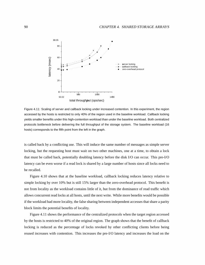
90 CHAPTER 4. SHARED STORAGE ARRAYS
50.02500µ 1000µ
1400µtotal throughput (ops/sec)¶
00
20
40
60
80
88.05
late
ncy
(mse
c)
server locking·callback lockling¸zero-overhead protocol
Figure 4.11: Scaling of server and callback locking under increased contention. In this experiment, the region
accessed by the hosts is restricted to only 40% of the region used in the baseline workload. Callback locking
yields smaller benefits under this high-contention workload than under the baseline workload. Both centralized
protocols bottleneck before delivering the full throughput of the storage system. The baseline workload (16
hosts) corresponds to the fifth point from the left in the graph.
is calledbackby a conflicting use. This will inducethesamenumber of messages assimple server
locking, but the requesting host mustwait on two other machines, one at a time, to obtain a lock
that mustbe calledback, potentially doubling latency before thedisk I/O canoccur. This pre-I/O
latency can beeven worse if a read lock is sharedby a largenumber of hostssinceall locksneedto
berecalled.
Figure 4.10 shows that at the baseline workload, callback locking reduces latency relative to
simple locking by over 10% but is still 15% larger thanthe zero-overhead protocol. This benefit is
not from locality asthe workload contains little of it, but from the dominanceof readtraffic which
allowsconcurrent read locksat all hosts, until thenext write. While morebenefitswould bepossible
if theworkload hadmorelocality, thefalsesharing between independent accessesthatshareaparity
block limits thepotential benefitsof locality.
Figure4.11shows theperformanceof thecentralizedprotocolswhenthetarget region accessed
by thehostsis restricted to 40%of theoriginal region. Thegraphshows thatthebenefit of callback
locking is reduced as the percentage of locks revoked by other conflicting clients before being
reused increaseswith contention. This increases thepre-I/O latency and increasesthe loadon the

4.5. SERIALIZABILITY PROTOCOLS FOR BSTS 91
10µ 40µ 60µ 80µ100µ
% disk accessed¹
00
10
20
30
40
50
60
64.29
late
ncy
(mse
c)server locking·callback lockling¸
Figure 4.12: The effect of contention on host latency for centralized locking protocols. Latency increases under
callback locking as the fraction of disk targeted by host accesses decreases. Contention increases from right
to left, as the % of disk accessed by the workload decreases. Callback locking reduces latencies compared to
server locking under moderate contention even for a random-access workload because the baseline workload
is mostly (65%) reads and shared locks are cached at each host. The graph shows that under high contention
(small fraction of disk accessed), the latency of callback locking increases relative to that of server locking
because caching brings little benefit as locks are revoked by conflicting clients before they are reused.
lock server. As the system size and load increases,the performance of both centralizedcallback
lockingandserver lockingbecomelimited by thecentral serverbottleneck.
Figure4.12shows theeffect of contentionon therelativeperformanceof thelockingprotocols.
When contention is high, closer to theorigin on the x-axis of thegraph, there is lit tle benefit from
lock caching. In thatcase, thepercentageof thediskthat theclientsareaccessing is relatively small,
resulting in frequent lock callbacksandhand-offs betweenclients. Whencontentionis low, callback
lockingshowsanoticeable reduction in response timeaslocksare reusedby clientsbefore they are
revoked.
4.5.3 Parallel lock servers
Thescalabilit y bottleneckof centralizedlockingprotocolscanbeavoidedby distributing thelocking
work acrossmultiple parallel lock servers. This can be achieved in two ways: a host can send
a single request to one of the lock serverswhich coordinate among themselves (ensuring proper
concurrency control andfreedom from deadlock) andreturn a single responseto thehost, or hosts

92 CHAPTER 4. SHARED STORAGE ARRAYS
can directly send parallel lock requests to the servers basedon a partitioning of locks. As the
first approach simply displaces the responsibility at thecostof more messaging, it is not discussed
further. Instead, thefocus in the remainingdiscussion is placedon partitionedlocks.
Becauselocksarepartitioned acrosslocksservers, whether by astatic or dynamicscheme,there
will alwaysbe some pairs of locks thatare on different servers. When a host attempts to acquire
multiple locks managedby multiple servers, deadlockscan arise. This canbeavoided if locks are
statically ordered and all hosts acquire locks in the same prescribed order, but this implies that
lock requests aresent to the lock servers one at a time — the next request is sent only after the
previousreply is received — and not in parallel, increasing latency and lock hold timesubstantially.
Alternatively, deadlocks can be detected via time-outs. If a lock request can not be serviced at
a lock serverafter a given time-out, a negative responseis returned to the host. A host recovers
fromdeadlock by releasingall theacquiredlocks, andretrying lock acquisition fromthebeginning.
While parallel lock servers employing a deadlock avoidance or detection schemedo not have the
bottleneckproblem,they suffer from increasedmessaging andusually longer pre-I/O latency. This
induceslonger lock hold time, increasing thechance of potential conflict comparedto anunloaded
single lock server.
4.5.4 Device-served locking
With theparamount importanceof I/O systemscalability and the opportunity of increasing storage
device intelligence,it seemed promising to investigate embedding lock servers in the devices. The
goal is to reducethecostof a scalable serializable storage array, and by specialization, increaseits
performance.Thespecializationsexploit the two-phasenatureof BSTs to piggy-back lock messag-
ingontheI/O requests,thereby reducing thetotalnumber of messages,andlatency. In device-served
locks,eachdevice serves locks for theblocks storedon it. This balances lock loadover all the de-
vices, enhancing scalability. Like any parallel lock server scheme, simple device-served locking
increases theamount of messaging and pre-I/O latency. Often, however, the lock/unlock messag-
ing canbeeliminatedby piggy-backing thesemessageson the I/O requests becausethelock server
and the storage device are the same. Lock requests are piggy-backedon the first I/O phaseof a
two-phasestorage transaction. To makerecovery simple, this schemerequiredthata host not issue
any devwrite requestsuntil all locks have been acquired, although it may issue devread requests.
Therefore,restarting anoperation in the lock acquisition phasedoesnot requirerecovering thestate
of theblocks (sinceno datahasbeenwrittenyet).

4.5. SERIALIZABILITY PROTOCOLS FOR BSTS 93
ºJ»�¼J½¾e¿JÀ;ÁyÂÃÅÄa½Â7» ºJ»�¼J½¾e¿JÀ;ÁyÂÄa»³Æ³Ç
ÈaÉ�ÊJËaÌ*Í*ÎJÏ9СÉ�ѳÒ7ÈaÐ ÏyÒÓ*ÔJÕСÌ*Í*ÎJÏ9СÑ�гÎJÖ
º;»�¼;½7¾e¿JÀ;ÁyÂÃÅÄa½Â7»
Ï9Ò7Ó*Ô;Õ7СÌ*Í*Î;ÏyÐ�ÉÅѳÒÈaÐ
×ÙØ ×ÙØ ×ÙØ
ÚÅÛ Ú©Û Ú©Û
× × ×
Ú©Û Ú©Û Ú©Û
×�Ø ×ÙØ ×ÙØ
Û Û Û
»³¾;ÇM¿;ÀJÁ9Â7Äa»�Ƴǻ³¾;Çe¿JÀ;ÁyÂÃÅÄa½Â7»»³¾;ÇM¿;ÀJÁ9Â7Ã�Äa½7»
ÜÜ Ü
Ý Ý
Figure 4.13: The breakdown of a host operation with device-served locking and the piggy-backing optimization.
A node represents a message exchange with a device. An ‘L’ node includes a lock operation, ’U’ stands for
an unlock operation, ‘LR’ represents the lock-and-devreadoperation, while ‘WU’ stands for devwrite-and-unlock.
The edges represent control dependencies. A ‘C’ node represents a synchronization point at the host, where
the host blocks until all preceding operations complete, restarting from the beginning if any of them fail. Lock
operations can fail if the device times out before it can grant the lock (‘A’).
In the case of single-phase writes, a lock phasemust beadded, preceding the writes, since the
lock and write requestscannot bebundled togetherwithout risking serializability. However, unlock
messagescan bepiggy-backedontowrite I/O requestsasshown in Figure4.13.
In thecase of single-phasereads, lock acquisition canbe piggy-backed on thereads,reducing
pre-I/O latency, but a separateunlockphaseis required. The latency of this additional phasecanbe
hiddenfromtheapplication sincethedatahasbeen received and theapplicationisnolongerwaiting
for anything. In thecaseof two-phasewrites, locks canbe acquiredduring the first I/O phase(by
piggy-backing the lock requestson thedevread requests) and releasedduring thesecond I/O phase
(by piggy-backing the unlock messages onto thedevwrite requests), totally hiding the latency and
messaging cost of locking.
This device-supported parallel locking is almost sufficient to eliminate theneedfor leased call-
back locks because two-phase writes have no latency overhead associated with locking and the
overhead of unlocking for single phase reads is not observable. Only single phasewrites would
benefit from lock caching.
Device-servedlocking is moreeffective thanthe centralizedlocking schemes,asshown in Fig-
ure 4.15 and Figure 4.16. With the baseline workload of 16 hosts, device-served locking causes
latencies only 6% larger than minimal. Despite its scalability, device-served locking hastwo dis-

94 CHAPTER 4. SHARED STORAGE ARRAYS
49.94Þ 500µ 1000µ1300µ
throughput (ops/sec)ß
00
5
10
14.84m
essa
ges
per
oper
atio
n
àdevice-served locksáserver locking·callback lockling¸timestamp orderingâzero-overhead protocol
Figure 4.14: The messaging overhead of the various protocols. Device-served locks require an explicit unlock
message for each block accessed. In the absence of retries, timestamp ordering requires one message per
read I/O request, resulting in lower messaging overhead.
49.94500µ 1000µ
1300µtotal throughput (ops/sec)¶
00
10
20
30
40
50
60
70
79
late
ncy
(mse
c)
server locking·callback lockling¸device-served locksázero-overhead protocol
Figure 4.15: Scalability of device-served locking compared to the centralized variants. Device served locking
comes within a few percent of delivering the full throughput of the storage system.

4.5. SERIALIZABILITY PROTOCOLS FOR BSTS 95
49.94500µ 1000µ
1400µtotal throughput (ops/sec)¶
00
20
40
60
80
88.05
late
ncy
(mse
c)server locking·callback lockling¸device-served locksázero-overhead protocolã
Figure 4.16: Scalability of device-served locking compared to the centralized variants under increased con-
tention. In this experiment, host accesses are restricted to 40% of the region targeted by the baseline workload.
Device served locking comes within a few percent of delivering the full throughput of the storage system.
advantages: it uses more messages than centralized locking protocols, as shown in Figure 4.14,
and it has performancevulnerabilit iesunder high contention dueto its susceptibility to deadlocks.
A component of the deadlock vulnerability disadvantage is the difficulty of configuring time-outs
for device-servedlocks. Note that although deadlocks may be uncommon, they have two second
ordereffects: they causea largenumber of requests to bequeuedbehind the blocked(deadlocked)
requestsuntil time-outs unlock the effecteddata; and, whendeadlocksinvolve multiple requestsat
multiple devices, time-outs lead to inefficienciesbecausethey restart more operations than neces-
sary to ensure progress. This results in an increasedmessaging load on the network and wasted
device resources for moremessageandrequest processing.
4.5.5 Timestampordering
Timestamp ordering protocols arean attractivemechanismfor distributed concurrency control over
storagedevicessince they placeno overheadon readsand are not susceptible to deadlocks. As in
thedatabaseimplementation, discussedin Section 2.4.2, timestamporderingworksby having hosts
independently determine thesame total order in which high-level operationsshould be serialized.
By providing information about that order (in the form of a timestamp) in each I/O request, the
intelligentstoragedevicescanenforce theordering and thereby serializability. Since I/O requests

96 CHAPTER 4. SHARED STORAGE ARRAYS
º;»�¼;½7¾e¿;ÀJÁ9Â7Ã�Äa½7»
ºJ»�¼J½¾e¿JÀ;ÁyÂÄa»³Æ³Ç
ÈaÉ�Ê;ËaÌ*Í*ÎJÏ9СÉÅѳÒÈaÐ Ï9Ò7Ó*Ô;Õ7Ð�ÌHÍ*Î;ÏyÐ�Ñ�гÎ;Ö
º;»�¼;½7¾e¿JÀ;ÁyÂÃÅÄa½Â7»
Ï9Ò7Ó*Ô;Õ7СÌ*Í*Î;ÏyÐ�ÉÅѳÒÈaÐ
äXå ä�å äXå
æ æ æ
ç ç ç
Ú Ú Ú
Ø Ø Ø
»³¾;Çe¿JÀ;ÁyÂÄa»³Æ³Ç
»³¾JÇe¿;ÀJÁ9Â7Ã�Äa½7»»³¾JÇe¿;ÀJÁ9Â7Ã�Äa½7»
è Ü
éAêyë&ìfí1é9ìéAêyë&ìfí1é9ì
Figure 4.17: The composition of host operations in the optimized timestamp ordering protocol. devread, de-
vwrite, and prewrite requests are denoted by ‘R’, ‘W’ and ‘P’ nodes respectively. ‘RP’ denotes a read-and-
prewrite request. A ‘C’ node represents a synchronization barrier at the host, where the host blocks until all
preceding operations complete, restarting from the beginning if any of them fail. Some of the prewrites or
reads may be rejected by the device because they did not pass the timestamp checks. In a two-phase write,
the prewrite requests are piggy-backed with the reads. Much like device-served locks of Section 4.5.4, single
phase writes still require a round of messages before the devwrite requests are issued.
49.94500µ 1000µ
1300µtotal throughput (ops/sec)¶
00
10
20
30
40
50
60
70
79
late
ncy
(mse
c)
server locking·callback lockling¸device-served locksátimestamp orderingâzero-overhead protocolã
Figure 4.18: Scalability of device-based protocols compared to the centralized variants. Both device-based
locking and timestamp ordering closely approximate the performance of the zero-overhead protocol, coming
within a few percent of the maximal throughput and minimal latency achievable under the zero-overhead
protocol.

4.5. SERIALIZABILITY PROTOCOLS FOR BSTS 97
are tagged with an explici t order according to which they have to be processed (if at all) at each
device, deadlocks can not occur andall allowed schedules are serializable. Instead of deadlock
problems, out-of-order requests will be rejected, causing their parent high-level operation to be
abortedandretriedwith a later timestamp.
The useof timestampordering based on loosely synchronized clocks for concurrency control
and for efficient timestampmanagement hasbeen demonstrated by the Thor client-server object-
oriented database management system [Adyaet al., 1995]. As in the database case, since each
device is performing a local check, a write request may pass the check in some devices, but the
high-level operationmayabort due to failedchecks in otherdevices.Thiscan lead to partial effects
of ahostwrite operation being applied to thestoragesystem. While atomicity in theevent of failures
is not a requirement of BSTs, it is not acceptable to allow non-failing storage systemsto damage
data routinely. To avoid partial updatesand theassociatedcomplex and expensive undooperations
they require, multi-device writesneed consensus before allowing changes. By split ting the write
protocol into a prewrite phasefollowedby a write phase, theprotocol ensures that all thedevices
take thesamedecision. This is consistent with timestampordering as implementedin databaseand
distributed systems. Theclusterof hostssharea loosely-synchronizedclock that is used to generate
timestamps. New timestampsare generated uniquely at a host by sampling the local clock, then
appending the host’s unique identifier to the least significant bits of the clock value. Each device
maintainstwo timestampsassociatedwith eachblock ( î�ï�ð and ñòï�ð ). Thedevicesimilarly maintains
a queueof requests, reads, writesandprewrites which areawaiting service(e.g. blockedbehind a
prewrite). óõôyöX÷Rï�ð denotesthe smallest timestampof a prewrite that hasbeen accepted in a spe-
cific block’s requestqueue.A refresher on timestamp ordering protocol with example scenariosand
algorithms is given in Section 2.4of thebackgroundchapter.
Theread-modify-writeprotocol wil l now bediscussed asan example sinceit employsthepiggy-
backing optimization andis of reasonable complexity. This protocol readsdata and parity in a first
phase, uses this data together with the “new data” to compute the new parity, then updatesboth
data andparity. The host starts by generating anew timestamp, ø�÷Rï�ð , thensends low-level I/O read
requeststo the data and parity devices, tagging each request with ø�÷dï�ð , and bundling eachrequest
with aprewrite requestasshown in Figure4.17.
The device receiving a “read-and-prewrite” request performs the necessary timestamp checks
both for a readand aprewrite, accepting therequestonly if both checkssucceed; that is ø�÷dï�ðúùûî�ï�ðand øü÷dï�ðýùþñòï�ð . An acceptedrequest is queued if ø�÷Rï�ðÿù ó ô9öX÷Rï�ð becausethere is anoutstanding

98 CHAPTER 4. SHARED STORAGE ARRAYS
prewrite with a lower timestamp,otherwisedata is returnedto thehost and îwï�ð is updated provided
that ø�÷Rï�ð ù î�ï�ð . When the host hasreceived all the data from the accepted “read-and-prewrite”
requests,it computesthenew parity andsendsthenew dataandparity in low-level write I/O requests
also tagged with ø�÷Rï�ð . The devices are guaranteed not to reject these writesby the acceptance of
theprewrites. In addition to doing thewrite,eachdevicewill update ñòï�ð , discardthecorresponding
prewrite request fromthequeue,and possibly increase ó ôAö�÷Rï�ð . Therequestqueueistheninspected
to seeif any reador read-and-prewrite requestscannow becompleted. Undernormalcircumstances,
the read-modify-write protocol doesnot incur any overhead, just like piggy-backeddevice-based
locking.
Several optimizations can be applied to the implementation of timestamp ordering to achieve
greaterefficiency. Theseoptimizationsaredescribednext. They wereimplemented in thesimulation
and all graphs includetheir effects.
Minimizingbuffering overhead
Theprotocol aspresentedcan induceahigh spaceoverheadto bufferwritten datawhenthere is
high overwrite and readactivity to overlapping ranges. If the storage device hasacceptedmultiple
prewrites to ablock, andtheir correspondingwritesarereceived out of order, thewriteswith largest
timestamps have to be buffered andapplied in timestamporder to satisfy any intermediate reads
in order. Our approach for avoiding excessive datawrite buffering is to apply writesas soon as
they arrive, rendering somelater writes unnecessary and somelater readswith a lower timestamp
impossible. As a result, these later readswith a lower timestampwill have to berejected. Although
readers can starve in this protocol if there is a persistent stream of writes, this is unlikely at the
storage layer. An important advantage of this immediate write processing approach is that storage
devicescan exploit their ability to streamdataathigh data ratesto thedisk surface.
Avoiding timestampaccesses
Thereadermayhave alreadynoticed that theprotocols require that the pair of timestamps îwï�ðand ñ ï�ð associated with each disk block be durable, read before any disk operation, and written
after every disk operation. A naive implementation might store these timestampson disk, nearby
the associated data. However, this would result in one extra disk access after reading a block (to
update the block’s î2ï�ð ), and one extra before writing a block (to readthe block’s previous ñ ï�ð ).Doubling the number of disk accessesis not consistent with the desired goal of achieving “high-
performance”.
As long as all clocks are loosely synchronized (to differ by a boundedamount) andmessage

4.5. SERIALIZABILITY PROTOCOLS FOR BSTS 99
Host latency Throughput Messages
(msec) (ops/sec) per operation
Centralizedlocking 63.8 800 12.6
Callbacklocking 57.0 800 11.2
Device-served locking 51.8 800 14.8
Timestampordering 51.6 800 10
Zero-overhead protocol 48.7 800 8.6
Table 4.3: Summary performance results of the various protocols under the baseline workload. The zero-
overhead protocol does not perform any control work, simply issuing I/Os to the devices and, hence, it does
not provide any correctness guarantees.
delivery latency is alsobounded, adeviceneednot accept a requesttimestampedwith avaluemuch
smaller than its current time. Hence, per-block timestampinformation older than�
seconds, for
some value to�
, can be discardedand a value of ����� � �used instead (where NOW stands
for current time). Moreover, if a device is re-initiated after a “crash” or power cycle, it can simply
wait time�
after its clock is synchronizedbeforeaccepting requests, or record its initial synchro-
nizedtimeandrejectall requestswith earlier timestamps. Therefore, timestampsonly need volatile
storage,and only enoughto record a few secondsof activity.
In our implementation, a devicedoes not maintain a pair of timestamps for each block on the
device. Instead, it maintains per-block read and write timestampsonly for those blocks that have
beenaccessed in thepast�
seconds. Theserecentper-block timestampsaremaintained in a data
structure, known asthe timestamp log. Periodically, every�
seconds,the devicetruncatesthe log
such that only timestampsthat are within�
seconds of current time are maintained.�
is known
asthe log truncation window. If an access is received to a block but the block’s timestamp is not
maintainedin thelog, theblock is assumed to haveatimestamp of ����� � , where ����� stands
for current time.
To understand why log truncation does not result in unnecessary rejections, recall that host
clocks are loosely synchronizedto within tensof milliseconds and message latency is bounded, so
a new requestarriving to a device will have a timestampthat is within tensof milli secondsof the
device’s notion of current time. Thedevice rejects a request if its timestamp ø�÷Rï�ð doesnot exceed
the maintainedvalues of î2ï�ð and ñ ï�ð . In particular, thedevicewill unnecessaril y reject the request
when ø�÷dï�ð exceeds the“real” readandwrite timestamps, î �����,î�ï�ð and î������,ñòï�ð , but when ø³÷xï�ð fails

100 CHAPTER 4. SHARED STORAGE ARRAYS
30µ 40µ 50µ 60µ 70µ 80µ90µ
read fraction (%)�
00
5
10
15
16.26
mes
sage
s pe
r op
erat
ion
àdevice-served locksáserver locking·callback lockling¸timestamp orderingâzero-overhead protocolã
Figure 4.19: The effect of (read/write) workload composition on messaging overhead for the various proto-
cols. Under read-intensive workloads, timestamp ordering comes close to the zero-overhead protocol. Its
messaging overhead increases as the fraction of writes increases. However, it still performs the least amount
of messaging across the range of workloads.
to exceedthe truncated values usedby thedevice, î�ï�ð and ñòï�ð . Considering only î2ï�ð , this means
that:
î������,îwï�ð��ûø�÷Rï�ð�� î�ï�ð
Replacing îwï�ð by its truncatedvalueof ������� �, the inequationbecomes:
î �����,î�ï�ð��ûø�÷Rï�ð���������� �
Thus,for arequestto berejectedunnecessarily, it mustbetimestampedwith avalue ø�÷Rï�ð thatis
morethan�
secondsin thepast, where�
isthelog truncation window. Thiscanbemadeimpossible
in practiceby selecting avalueof�
that is many multiplesof theclockskew window augmentedby
thenetwork latency. A�
of afew secondslargely satisfiesthis need. This minimizesthechancethat
a requestwil l be receivedand rejected becauseof aggressive reduction of thenumber of accurately
maintained timestampskept in thedevicecache.
In addition to being highly scalableasil lustratedin Figure4.18,anotheradvantageof timestamp
ordering is that it uses thesmallestamount of messaging compared to all the other protocols (Fig-
ure4.19). It hasno messaging overheadon reads, and with thepiggy-backing optimization applied,
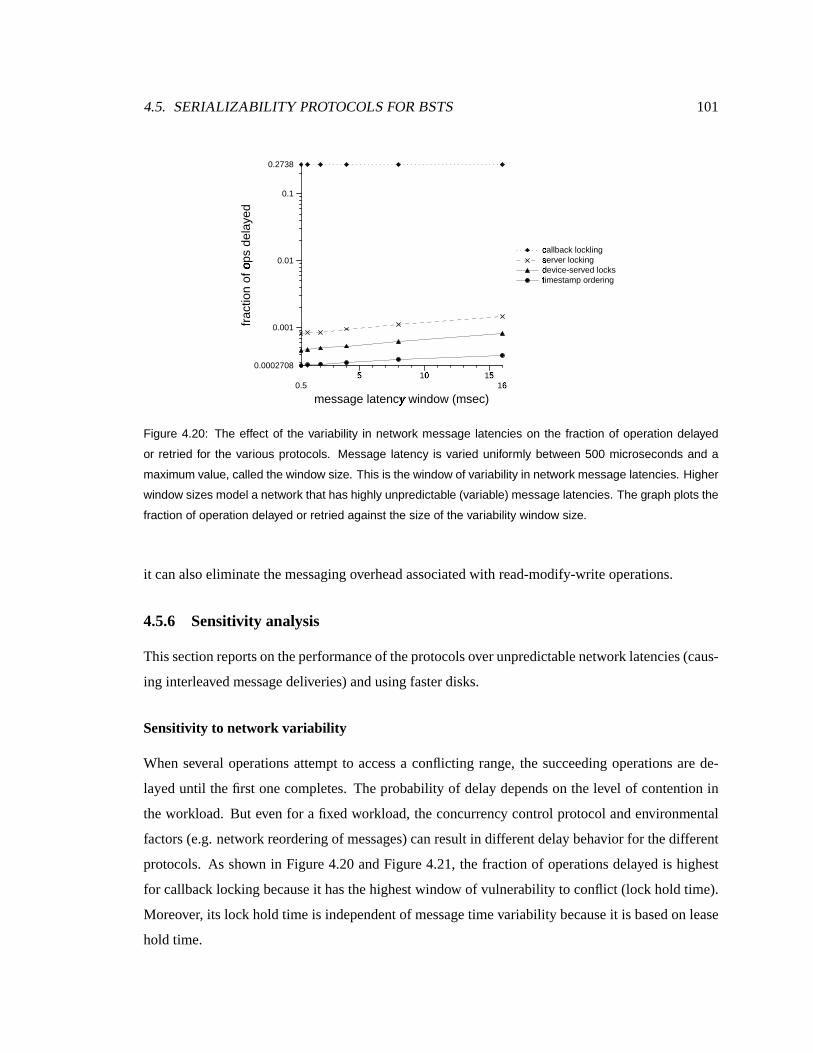
4.5. SERIALIZABILITY PROTOCOLS FOR BSTS 101
0.55�
10µ 15�
16�message latency window (msec)�
0.0002708
0.001
0.01
0.1
0.2738
frac
tion
of o
ps d
elay
ed� callback lockling¸
server locking·device-served locksátimestamp orderingâ
Figure 4.20: The effect of the variability in network message latencies on the fraction of operation delayed
or retried for the various protocols. Message latency is varied uniformly between 500 microseconds and a
maximum value, called the window size. This is the window of variability in network message latencies. Higher
window sizes model a network that has highly unpredictable (variable) message latencies. The graph plots the
fraction of operation delayed or retried against the size of the variability window size.
it canalsoeliminatethemessaging overhead associatedwith read-modify-writeoperations.
4.5.6 Sensitivity analysis
This sectionreportson theperformanceof theprotocols over unpredictable network latencies(caus-
ing interleavedmessagedeliveries) and using fasterdisks.
Sensitivit y to network variabili ty
When several operations attempt to accessa conflicting range, the succeeding operations are de-
layeduntil thefirst onecompletes. The probabilit y of delay depends on the level of contention in
the workload. But evenfor a fixedworkload, theconcurrency control protocol and environmental
factors (e.g. network reorderingof messages)can result in different delay behavior for thedifferent
protocols. As shown in Figure 4.20and Figure 4.21, the fraction of operationsdelayed is highest
for callback locking becauseit has thehighest window of vulnerability to conflict (lock hold time).
Moreover, its lock hold time is independent of message timevariability because it is based on lease
hold time.

102 CHAPTER 4. SHARED STORAGE ARRAYS
0.55�
10µ 15�
16�message latency window (msec)�
00
50
100
118.4
late
ncy
(mse
c)
server locking·callback lockling¸device-served locksátimestamp orderingâ
Figure 4.21: The effect of the variability in network message latencies on host latency for the various protocols.
Message latency is varied uniformly between 500 microseconds and a maximum window size. The graph plots
latency against the size of the variability window size.
Distributeddevice-basedprotocols both do better thancallback locking and server locking be-
causethey exploit piggy-backingof lock/ordering requestsontheI/Os,thereby avoiding thelatency
of communicating with the lock server before starting the I/O and shortening the window of vul-
nerabili ty to conflict. Both device-basedprotocols, however, are potentially moresensitive to the
messagetransport layer, or moreprecisely, to messagearrival skew. Messagearrival skew can cause
deadlocksandrestarts for device-served locks,and rejectionsandretriesfor timestampordering be-
causeconcurrentmulti -devicerequestsareservicedin adifferentorderat different devices.Restarts
and retriesarealso countedasdelaysand arethereforeaccountedfor in Figure4.20.
To investigatethe effect of messageskew on the delay and latency behavior of the protocols,
an experiment was conducted wheremessagelatency variabili ty was changedand the effects on
performancemeasured. Message latency wasmodeled as a uniformly distributedrandom variable
over a given window size, extending from � to ws milli seconds. A larger window size implies
highly variable messagelatenciesand leadsto a higher probabili ty of out-of-order messagearrival.
Figures4.20and4.21graph thefraction of operationsdelayedand host end-to-end latency against
thenetwork delay variabili ty window sizews. All schemessuffer fromincreasedvariability because
it also increasesthemeanmessage delivery time. However, timestampordering and device-based
locking slow down li ttle morethanthezero-overheadprotocol. But high messagevariabilit y plagues
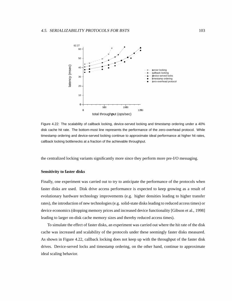
4.5. SERIALIZABILITY PROTOCOLS FOR BSTS 103
0µ 500µ 1000µ1350�
total throughput (ops/sec)¶
00
10
20
30
40
50
60
62.27
late
ncy
(mse
c)server locking·callback locking¸device-served locksátimestamp orderingâzero-overhead protocolã
Figure 4.22: The scalability of callback locking, device-served locking and timestamp ordering under a 40%
disk cache hit rate. The bottom-most line represents the performance of the zero-overhead protocol. While
timestamp ordering and device-served locking continue to approximate ideal performance at higher hit rates,
callback locking bottlenecks at a fraction of the achievable throughput.
thecentralizedlocking variantssignificantly moresincethey performmorepre-I/O messaging.
Sensitivit y to faster disks
Finally, oneexperiment wascarried out to try to anticipate the performanceof theprotocols when
faster disks are used. Disk drive accessperformance is expected to keep growing asa result of
evolutionary hardware technology improvements (e.g. higher densities leading to higher transfer
rates), theintroductionof new technologies(e.g.solid-statedisksleading to reducedaccesstimes) or
deviceeconomics(droppingmemory pricesandincreaseddevicefunctionality [Gibson etal., 1998]
leading to larger on-diskcachememorysizesand thereby reduced access times).
To simulatetheeffect of faster disks,an experiment wascarriedout wherethehit rateof thedisk
cachewasincreased andscalability of theprotocols under theseseemingly faster disks measured.
As shown in Figure4.22, callback locking doesnot keepup with thethroughput of the faster disk
drives. Device-served locks andtimestampordering, on the other hand, continue to approximate
idealscaling behavior.

104 CHAPTER 4. SHARED STORAGE ARRAYS
4.6 Caching storagecontrollers
In thediscussion sofar, we assumed that data caching is performed on thedevice side. The client-
side controllers did not cache data or parity blocks. This design implies that a read by a BST
executing at a storage controller invokesa message to the device storing that data. The device
servicesthereadand returnsthe data to the requesting controller. The controller passes this datato
thehostor usesit to computethenew parity, but in eithercasesdiscards it after theBST completes.
Sucha cache-lesscontroller design is acceptable when the storage network connecting de-
vicesand controllers has relatively high-bandwidth and low latency. In such a case, the time
taken by a controller to read a block from a device’s cache is comparable to a local read from
the controller’s own memory. If this holds, there is benefit from avoiding double-caching the
data blocks at thestorage controller. Controller-sidecaching is wasteful of memory since a block
would be soon replicated in the device’s cache and in the controller’s cache. It also induces un-
necessary coherence traffic when blocks arecached at multiple controllers have to be kept up-to-
date [Howard etal., 1988, Lamb etal., 1991, Carey etal., 1994]. This coherencetraffic canhave a
negativeeffect onperformanceunderhigh contention.
False sharing occurs when higher level software is writing to objects that are smaller than the
block-size of thecontroller’s cache, called the “cacheblock size.” In this case,two applicationsor
application threadsrunning on two clientscanbewriting to two objects which happento fall in the
same “storage block.” Such a scenario induces coherence traffic between the controllers to keep
their copiesof the block up-to-date even though theremay be no overlapping accesses. Another
kind of false sharing arises from contention over parity blocks when two controllers write to the
same stripe. Becausefalse sharing is expected at the storage layer, it is generally undesirable to
cacheat theparallel controller or hostunlessthenetwork is substantially slower thanlocal accesses.
Another reason against caching is the fact that higher level system software, e.g. filesystems and
databases,have their own caches,which will absorb “ locality induced” reads. Replicating these
blocks in thehost’s filesystembuffer cacheand in thecontroller’s cache is wasteful of memory.
So, if thefilesystem or database cache absorbs most application reads, when is caching at the
parallel controller useful atall? Caching at thecontroller canyieldperformancebenefitsin anumber
of situations. First, caching at thecontroller avoids thenetwork andreducesthe loadon thedevices.
When the network is slow, this can translate into dramatic benefits. Furthermore, offloading the
devices improve scaling. For example, controller-side caching caneliminate the “ read phase” in
two-phased BSTs. Many BSTs described in Section 4.3 pre-reada data or a parity block before

4.6. CACHING STORAGE CONTROLLERS 105
Nü
etwork S�
witched
����
. .
C�
C�
C�
C�
C�
.
S�
torage devices
hostread/hostwrite
reply
����
�
�
�
����
!#"%$'&("')#!!#)#*+)
hostread/hostwrite
reply
hostread/hostwrite
reply
cache s
�torage deviec
Figure 4.23: In a caching storage array, parallel storage controllers receive host requests and coordinate
access to the shared storage devices. Data blocks are cached at the device where they are stored and also
on the storage controllers. Consequently, some reads in a BST are serviced from the cache on the controller,
avoiding a network message to the device.
writing it. Caching theseblocks on the controller sidecanavoid network transfers from the device
caches. This cantranslateinto dramatic reductionsin latency whenthe network is overloaded, and
when there is litt le write contention acrosscontrollers for blocks. Low contention increases the
chancethata block cachedat controller A is not updated by another controller beforecontroller A
accessesthesameblockagain, making caching it worthwhile.
Caching at theparallel controller can alsoprove useful when the application working setdoes
not fit in the filesystem cache. In this case, the controller’s cache can be used to cache blocks
that have been evicted from higher-level caches (the filesystem buffer cache for example). The
controller in this casemust coordinate its cache replacement policy with the higher level cache.
Recent work has shown that such an approach can yield sizeable benefits for certain applica-
tions[WongandWilkes,2000].
Figure4.23depictsasharedarraywheredatablocksarecachedattheparallel storagecontrollers
aswell at thestoragedevices. When a storage controller caches data andparity blocks, pre-reads
can besatisfied from its local cache. Precisely, a read by a BST executing locally can beserviced
from thelocal cache.
The distributedserializabilit y protocols discussed in the previous section do not readily apply
to this architecture. Both device-served locks and timestamp ordering rely on the storage device

106 CHAPTER 4. SHARED STORAGE ARRAYS
receiving requeststoperformconcurrency control checksbeforeservicing them.Going to thedevice
for serializability checks when thecontroller has the datain its cache seemsto defeat thepurpose
of client-side caching. This section focuses on the two distributedprotocols which were shown in
the previous sectionsto have nicescaling properties.It outlineshow they can be extendedto allow
effective controller-side caches. We assume that for both protocols, storagecontrollers cache data
blocks in a local cache, called the controller cache. A devwrite writesdata through the cacheto
the storage device, updating both the local copy andthestoragedevice. A devread is servicedby
checking thecache first. If a valid copy exists, the block is read locally, otherwisea it is retrieved
fromthestoragedevice.
4.6.1 Device-served leases
As in device-served locking in Section 4.5.4, locks areacquired from the devices. The protocol
is also two-phase, guaranteeing serializability: All locks needed for the execution of a BST are
acquired before any of them is released. The key differencebetween device-served locking and
device-served leasesis that in the latter, the locks are not released immediately after they areac-
quired in thefirst phase.Instead, locksarecachedat thehost. Consequently, bothablock’scontents
and the associated lock are cachedby the controller. A devread is serviced exclusively from the
controller’s localcache if both theblock and a lock for it are found in thecontroller’s cache.
Like thecallback locking approach of Section 4.5.2,locks expire after a specified time period,
hence thename“ lease”. This time period is known asthe lease duration. A lock is valid until the
leasedurationexpiresor until it is explicitl y revokedby thedevicein a revokeLeasemessage(which
is analogousto a callback). When a lease expires or is revokedby the device that granted it, the
block in thecacheis consideredinvalid and is logically discarded from thecache. A BST devread
would then have to be forwarded to the device. The devread is piggy-backed with a lock request
asin device-servedlocking. Thecontroller sends a lock-and-devread messageto the device,which
respondswith thedataafter thelockcanbegrantedto the requestingcontroller.
Figure 4.24 depicts how these BSTs break down into basic operations. The piggy-backing
optimization is stil l applied. If a block is not found in the cache, a lock-and-devreadrequest is sent
to the device where the block is stored. However, locks are not released in the post-readphase, but
are instead cached locally. On the device-side, requests to lock, readand write are serviced asin
device-served locking,except for onedifference. In device-servedlocking, locksarenot cachedand
are released immediately after the BST completes. Thusa device that can not grant a lock due to
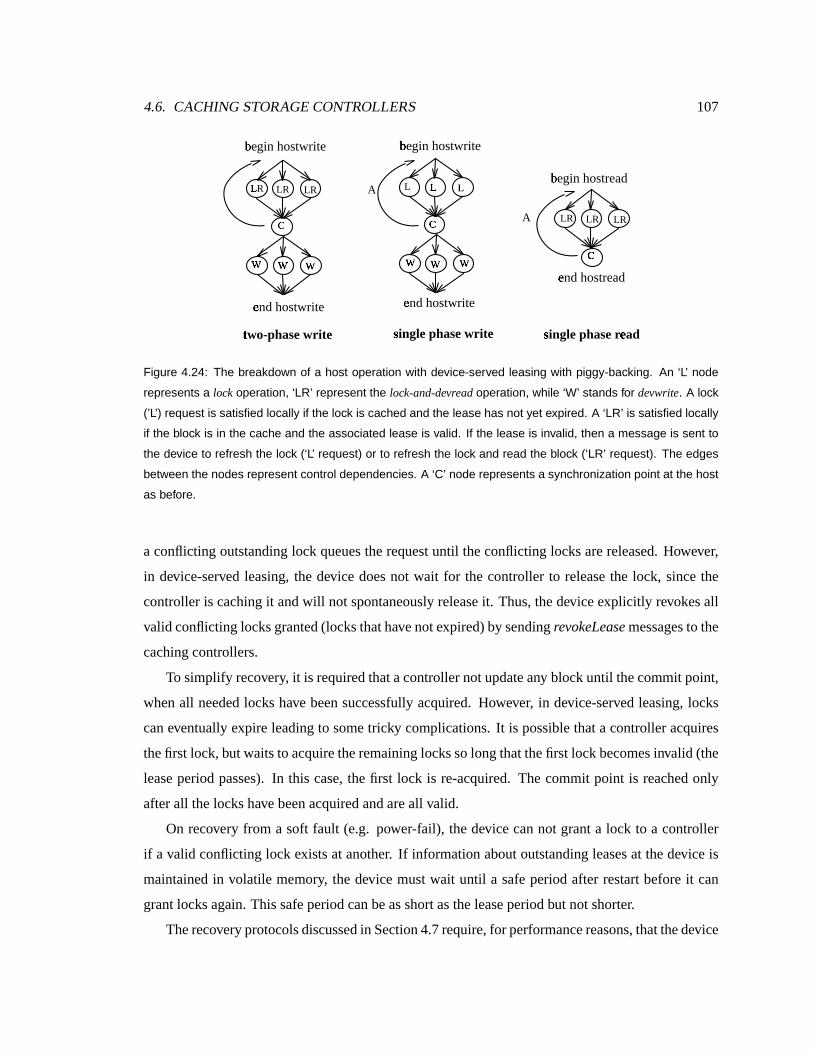
4.6. CACHING STORAGE CONTROLLERS 107
bºegin hostwrite
bºegin hostread
tÈwo-phase wr ite s
Ïingle phase r e
Ðad
bºegin hostwrite
sÏingle phase wr ite
L×
R LR LR
WÚ
WÚ
WÚ
L L×
L×
WÚ
WÚ
WÚ
LR LR LR
e»nd hostread
e»nd hostwrite e
»nd hostwrite
CÜ
CÜ
CÜ
A
A
Figure 4.24: The breakdown of a host operation with device-served leasing with piggy-backing. An ‘L’ node
represents a lock operation, ‘LR’ represent the lock-and-devreadoperation, while ‘W’ stands for devwrite. A lock
(’L’) request is satisfied locally if the lock is cached and the lease has not yet expired. A ‘LR’ is satisfied locally
if the block is in the cache and the associated lease is valid. If the lease is invalid, then a message is sent to
the device to refresh the lock (‘L’ request) or to refresh the lock and read the block (‘LR’ request). The edges
between the nodes represent control dependencies. A ‘C’ node represents a synchronization point at the host
as before.
a conflicting outstanding lock queues the request until theconflicting locks are released. However,
in device-served leasing, the device does not wait for the controller to releasethe lock, since the
controller is caching it and will not spontaneously releaseit. Thus, the device explicitly revokesall
valid conflicting locksgranted(locksthathavenot expired) by sending revokeLeasemessagesto the
cachingcontrollers.
To simplify recovery, it is requiredthatacontroller not updateany block until thecommit point,
whenall needed locks have beensuccessfully acquired. However, in device-served leasing, locks
can eventually expire leading to some tricky complications. It is possible that a controller acquires
thefirst lock, but waits to acquiretheremaining locksso longthatthefirst lock becomesinvalid (the
leaseperiod passes). In this case,the first lock is re-acquired. The commit point is reached only
afterall the lockshavebeen acquiredandareall valid.
On recovery from a soft fault (e.g. power-fail), the device can not grant a lock to a controller
if a valid conflicting lock exists at another. If information about outstanding leasesat thedevice is
maintainedin volatile memory, the device must wait until a safe period after restart before it can
grantlocksagain. Thissafe period can beasshort as theleaseperiod but not shorter.
Therecoveryprotocols discussed in Section 4.7require,for performancereasons,thatthedevice

108 CHAPTER 4. SHARED STORAGE ARRAYS
beable to identify theset of leasesthat maybevalid and outstanding at the controllersat theevent
of a failure. This identification doesnot have to beaccurate and canover-approximate this set, as
longas it is a relatively small fractionof theblockson thedisk.
4.6.2 Timestampordering with validation
Device-servedleasing distributescontrol work acrossthedevicesand hosts. It doesnot havea cen-
tral scalabili ty bottleneck. Nevertheless, it hastwo serious disadvantages. First, it cansuffer from
degradedperformanceundercontention. Lock acquisitioncanhavesubstantial latency due to revo-
cation messaging. Furthermore,spuriousrestartsunder contention cancausedegradedperformance.
Second, it is relatively complex to implement. Timestamp ordering has thescalability advantages
of device-served leasing without the vulnerabili ty to contention or to spurious restarts (since it is
deadlock-free). Timestamp ordering, however, doesnot readily support caching and it hasno locks
which can beeasily overloadedto ensurecachecoherence.
To extend timestamp ordering to support controller-sidecaching in a straight-forwardmanner,
we wil l replacecache hits with version test messagesto thedevices.This will only have a negative
on read hit latency if all data needing to be read is in the controller’s local cache. The controller
cachesdata blocks together with their write timestamps, ñ ï�ð . Each block in a controller’s cacheis
associatedwith an ñòï�ð , which is the write timestamppublicized by the device for that block when
the controller readthe block into its cache. Intuitively, this ñòï�ð canbe thought of as a version
number. If another controller writes its copyof theblock, the ñ ï�ð for thatblock is updatedon the
device, logically making theversion cachedby othercontrollersinvalid. It suffices to compare the
local ñ ï�ð in thecontrollercachewith thatmaintainedat thedevice to verify whether thedeviceand
controller blocksare thesame.
Thecontrollersand devicesbehaveasin thebasic timestampordering, except for thereadphase
of a single or two-phase BST. In this case, the controller services the readfrom its local cache if
a local block exists. To validate that the local version of theblock is not stale and thereby is safe
to read, a readIfInvalid 1 messageis sent to the device for eachblock. This messagecontains the
timestamp of theBST, ø³÷xï�ð , and thewrite timestamp of theblock readfrom thecache, ñ ï�ð . If the
ñ ï�ð of thecachedblockmatchesthe ñ ï�ð maintainedby thedevice, thentheread performed by the1This means readif the local copycachedat thehost is invalid. Thedevice either returnsanOK response validating
thatthe localcopycached at thehost is valid, or, if thevalidation fails, returnsthenew contentsof the blockand the new
associated,.-(/ .
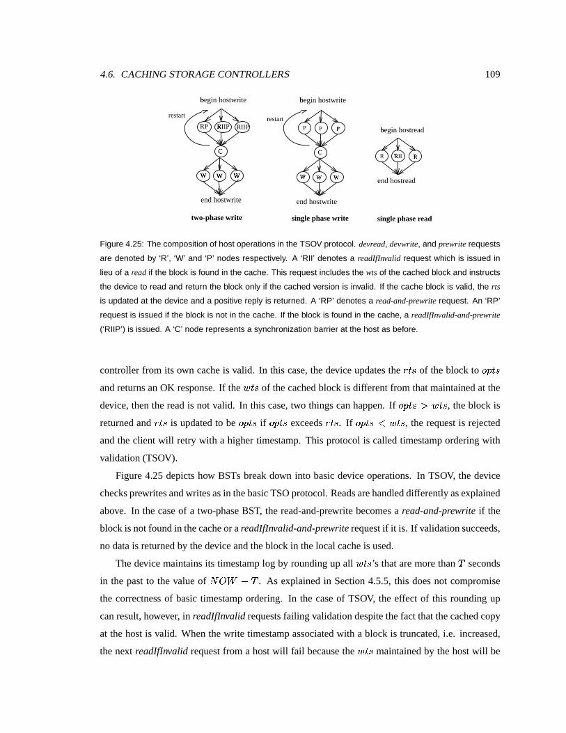
4.6. CACHING STORAGE CONTROLLERS 109
b0
egin hostwrite
b0
egin hostread
two-phase wr ite single phase r ead
b0
egin hostwrite
single phase wr ite
RP R1
IIP RIIP
W2
W2
W2
P P P3
W4
W4
W4
R R5
II R5
end hostread
end hostwrite end hostwrite
C6
C7
r8 estart restart
Figure 4.25: The composition of host operations in the TSOV protocol. devread, devwrite, and prewrite requests
are denoted by ‘R’, ‘W’ and ‘P’ nodes respectively. A ‘RII’ denotes a readIfInvalid request which is issued in
lieu of a read if the block is found in the cache. This request includes the wtsof the cached block and instructs
the device to read and return the block only if the cached version is invalid. If the cache block is valid, the rts
is updated at the device and a positive reply is returned. A ‘RP’ denotes a read-and-prewrite request. An ‘RP’
request is issued if the block is not in the cache. If the block is found in the cache, a readIfInvalid-and-prewrite
(‘RIIP’) is issued. A ‘C’ node represents a synchronization barrier at the host as before.
controller from its own cacheis valid. In this case, the device updates the îwï�ð of the block to ø�÷Rï�ðand returnsanOK response. If the ñòï�ð of the cachedblock is different from that maintained at the
device, thenthereadis not valid. In this case, two things can happen. If ø�÷Rï�ðõù ñ ï�ð , the block is
returnedand î2ï�ð is updated to be ø³÷xï�ð if ø³÷xï�ð exceeds îwï�ð . If ø�÷Rï�ð9� ñòï�ð , the request is rejected
and the client will retry with a higher timestamp. This protocol is called timestampordering with
validation (TSOV).
Figure 4.25 depicts how BSTs breakdown into basic device operations. In TSOV, the device
checksprewritesandwritesasin thebasicTSOprotocol. Readsarehandleddifferently asexplained
above. In thecaseof a two-phaseBST, the read-and-prewrite becomesa read-and-prewrite if the
blockis not found in thecacheor areadIfInvalid-and-prewriterequest if it is. If validation succeeds,
no data is returned by thedeviceand theblock in the local cache is used.
Thedevice maintains its timestamplog by rounding up all ñòï�ð ’s that aremore than�
seconds
in the past to the value of ���� � �. As explained in Section 4.5.5,this does not compromise
the correctness of basic timestampordering. In the caseof TSOV, the effect of this rounding up
can result, however, in readIfInvalid requests failingvalidation despite thefact that thecached copy
at thehost is valid. Whenthewrite timestampassociated with a block is truncated, i.e. increased,
the next readIfInvalid request from a host will fail because the ñ ï�ð maintainedby thehost will be

110 CHAPTER 4. SHARED STORAGE ARRAYS
0µ 100µ 200µ 300µ 400µ412.6
total throughput (ops/sec)¶
00
20
40
60
80
92.29
late
ncy
(mse
c)
device-served locksádevice-served leasesátimestamp validationâ
Figure 4.26: The scalability of device-served leases and timestamp ordering with validation. The storage
controllers have a local cache that is big enough such that no blocks are evicted because of limited cache
capacity. The lease duration is 240 seconds, and the timestamp log truncation window is 300 seconds. The
graph also shows the performance of device-served locking (which is also representative of that of basic
timestamp ordering) when the controllers do not cache any blocks.
smaller thanthe truncatedvaluemaintainedby the device. This inducesanunnecessary readof the
data from the device. Therefore, in TSOV, the timestamplog truncation window must be longer
thanafew seconds. For theimplementation evaluated in thissection, avalueof 5 minuteswasused.
The following subsections compare and contrast the performance of the cache coherent dis-
tributed protocols. In particular, the evaluation criteria are takento bethe latency of completing a
BST, theamount of network messaging performed,the fraction of operations delayed or blocked,
thesizeof device-sidestate,and theimplementationcomplexity of theprotocols (both atthedevices
and at thecontrollers).
4.6.3 Latency and scaling
Recall thata caching storage controller forwardsdevwritesto thedeviceunder both protocols. De-
vreads, however, arehandled differently. Under TSOV, a control messageis sent to the device to
validatea locally cached block and local contents are readif the validation succeeds. If the vali-
dation fails, the device returns the new contents of the block or the request is rejected (dueto an
unacceptable timestamp). Consider the case of low contention, where blocks cached at one con-

4.6. CACHING STORAGE CONTROLLERS 111
troller arenot soonwrittenby another. In thiscase,thevalidationwill often succeed. Thedifference
betweenTSO andTSOV is that the latter convertsthe pre-reads or readsin case of a cache hit to
a control messageexchange with the device. Device-servedleasing (DLE) completely eliminates
messaging in caseof acachehit. Theblock isread fromthecacheif thelocally cached leaseisvalid.
However, whena lock is not cachedlocally at the host, one must beacquired from thedevice. The
device must recall all the conflicting and outstanding leasescachedby all hosts beforeresponding
to therequesting host. This induceslatency whenan exclusive lock is requestedby a controller for
ablock that hasbeencachedat many hostsin shared mode.
Themajor vulnerabili ty of device-servedleasingis that this work is performed by thedeviceand
not by the controller which can load the device in large systems. Under timestampordering with
validation, ahostA writes to thedevicesby sending aprewritemessagein afirst phasefollowed by
a write messagein a second phase. Other hosts that have a cachedcopy of the block written to by
host A are not notified. They wil l discover that theblock hasbeenupdated when and if they try to
validate thereadlater. Thework to keepthe caches coherent is delayeduntil (and if) an accessis
performed.
When eachhost accessesa different part of the device, leasing works well. However, when
controllersshare accessto thesamedevicesand objects, device-served leasing can be expected to
suffer becauseof increasedmessaging and device load. Sharedarraysarenot characterizedby sep-
aratelocality ateach controller, however. First, becauseclusterapplications running on topof them
oftenbalanceloaddynamically acrossthehostsresulting in blocksbeing accessed by multiplehosts
within ashort period of time. Second, even if applicationshave locality in thelogical addressspace,
RAID can maptwo logically different objects to thesame stripe set. This inducescontention not
only on the parity blocks but also on thedata blocks themselvesdue to RAID write optimizations
which sometimesrequire reading blocks that arenot being updated. Under highcontention, valida-
tion messagesof TSOV will oftenfail, andthedevicewill thenreturn thenew contentsof theblock.
TSOV thus reducesin this caseto basic timestamporderingwith no caching. DLE under highcon-
tention also generatesa lot of lease revocationswhich also makeit perform asbasic device-served
locking. The revokeleasemessage in DLE is theequivalent of theunlock messagein device-served
locking. However, adevice underDLE is expectedto suffer from blocking longerbecauseits locks
are distributed acrosshosts and revocations will tend to be queued and wait for service at more
nodes. More importantly, DLE is more vulnerable to deadlocks than basic device-served locking
because longer blocking timescause more spuriousdeadlock detection time-outs, each initiating

112 CHAPTER 4. SHARED STORAGE ARRAYS
99.98200µ 300µ 400µ 500µ
550.1µthroughput (ops/sec)ß
00
5
10
15
15.75
mes
sage
s pe
r op
erat
ion
à device-served locksádevice-served leasesátimestamp validationâ
Figure 4.27: The messaging overhead of device-served leases and timestamp ordering with validation, com-
pared to that of device-served locking. The latter assumes no controller-side caches. Note that under high
load, device-served leasing (DLE) induces more messging than device-served locking. This is because the
fraction of operations retried (to avoid a likely deadlock) under high load is larger under DLE than under
device-served locking. Deadlock-induced timeouts are more likely under DLE because lock hold times are
longer under DLE (lease duration) than under device-served locking (duration of the operation).
restartswhich further loads thedevices.
The baseline workload and simulation parametersdescribedin Table 4.2 are used to evaluate
the caching protocols, except for the system being third as large (10 devicesand 8 hosts). Simu-
lating the more complex caching protocols requires moreresources making large scalesimulations
impractical. All thegraphs in Section 4.6and latercorrespond to 8 hostsand10 devices.
Figure 4.26plots latency versus throughput of TSOV, DLE anddevice-served locks. Device-
servedlocking corresponds to theperformancein theabsenceof host-sidecaching. Suprisingly, the
graphsshows thattimestamp ordering exhibits lower latenciesthan DLE. Both TSOV and DLE re-
ducelatenciescompared to device-servedlocking without host-side caching. However, thecaching
benefit of DLE is somewhat offset by the increasedload on the devices for leasemanagement and
recall aswell asby theincreased messaging leasesinduce when hosts contend for a sharedstorage
space.

4.6. CACHING STORAGE CONTROLLERS 113
4.6.4 Network messaging
TSOV doesnot reducethe number of messages sent on thenetwork over TSOalthough it converts
somedatatransfersto control messages, reducing thetotal number of bytestransferred. DLE,onthe
otherhand, eliminatespre-reads and reads altogetherwhena requesthits in thecachebut requires
revocation messaging whendata is shared. Figure4.27plots the averagenumber of messagesper
operation (thatis,per BST) for eachprotocol. TSOV hasa relatively constant number of messages
per BST, and equal to that of basic TSO. Similarly, device-served locking hasa relatively constant
messaging overhead. DLE starts with the lowest messaging overhead when the number of hosts
is limited(2) and few lease revocationsoccur. As thenumber of hosts in thesystem increases, the
amount of messaging requiredto revokeleasesincreases. At thesametime, leasesarerevokedmore
often, requiring hoststo re-acquire themmore frequently. Underhigh throughput, this degrades to
worse than the performanceof device-served locking becauseof the large number of operations
retried under DLE. This is due to the fact that DLE is morevulnerable to the deadlock detection
time-outs.
WhenaBSTisstartedatahost, it oftenpartially hits in thecachesuchthatsomeblocksand their
leases are found in the cachewhile someothersare not. Theblocks that are not in thecacheor for
which no valid leasesare cachedmust bere-fetchedfrom the device. This hold-and-wait condition
of holding some locks locally and attempting to acquire the rest (from multiple devices) opens
the possibili ty of deadlocks. Both device-served locking and DLE have a similar time-out based
deadlock detection mechanism at the devices. However, DLE suffers much moretimeout-induced
restarts. This is becauseDLE holdslockslongerby cachingthemand thereforeismorevulnerable to
deadlockswith many moreBSTsthatstartwhile the locksarelocally cached. Furthermore, because
the leaserevocation work at somedevicescantake considerably long, deadlockeddetection time-
outscanoftenexpire in themeantime.
4.6.5 Read/write composition and locality
Under a predominantly read workload, where blocks are rarely invalidated by writes from other
hosts, device-served leasing yieldssimilar latenciesto timestamp ordering with validationasshown
in Figure4.28. Figure4.29graphsthemessaging overheadof theprotocols asafunction of theread
traffic ratio in the baseline workload. Under a predominantly readworkload, device-served leases
induceslower messaging overheaddue to the large fraction of local cache hits. However, asthe
fraction of writes increase,and becausehosts accessa sharedstoragespaceuniformly randomly in
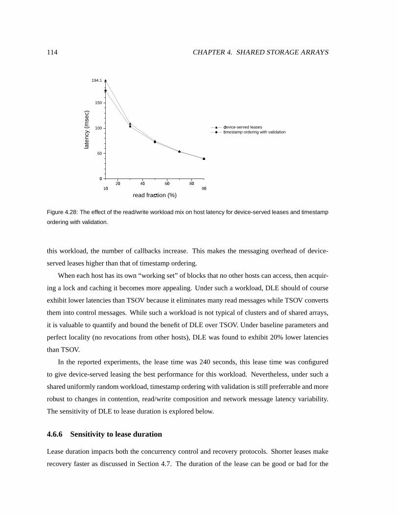
114 CHAPTER 4. SHARED STORAGE ARRAYS
10µ 20µ 40µ 60µ 80µ90µ
read fraction (%)�
00
50
100
150
194.1
late
ncy
(mse
c)
device-served leasesátimestamp ordering with validationâ
Figure 4.28: The effect of the read/write workload mix on host latency for device-served leases and timestamp
ordering with validation.
this workload, the numberof callbacks increase. This makes the messaging overhead of device-
servedleaseshigherthan that of timestampordering.
When eachhosthasits own “working set” of blocks that no other hostscanaccess, thenacquir-
ing a lock and caching it becomesmore appealing. Under such a workload, DLE should of course
exhibit lower latenciesthanTSOV becauseit eliminatesmany readmessageswhile TSOV converts
theminto control messages. While such a workloadis not typical of clusters and of sharedarrays,
it is valuable to quantify and bound thebenefit of DLE over TSOV. Under baseline parametersand
perfect locality (no revocations from other hosts), DLE wasfound to exhibit 20% lower latencies
thanTSOV.
In the reported experiments, the leasetime was 240 seconds, this lease time wasconfigured
to give device-served leasing the bestperformance for this workload. Nevertheless,under such a
shared uniformly randomworkload, timestampordering with validation is still preferrableandmore
robust to changes in contention, read/write composition and network message latency variabili ty.
Thesensitivity of DLE to leaseduration is explored below.
4.6.6 Sensitivity to leaseduration
Lease duration impacts both theconcurrency control and recovery protocols. Shorter leases make
recovery faster as discussed in Section 4.7. The duration of the lease canbe good or badfor the

4.6. CACHING STORAGE CONTROLLERS 115
10µ 20µ 40µ 60µ 80µ90µ
read fraction (%)�
00
5
10
15
19.7
mes
sage
s pe
r op
erat
ion
à device-served leasesátimestamp ordering with validationâ
Figure 4.29: The effect of the read/write workload mix on messaging overhead for device-served leases and
timestamp ordering with validation. Messaging overhead for both protocols decreases as the ratio of reads
increases. When write traffic dominates, timestamp ordering with validation induces a lower messaging over-
head than device-served leasing, which suffers from revocation messaging and time-out induced retries.
15� 100µ 200µ 300µ
360�Lease duration (sec)¹
0.2705
0.316228
0.398107
0.501187
0.6269
bloc
ked
or r
etrie
d op
erat
ions
(pe
r op
)
�device-served leasesá
Figure 4.30: The effect of lease duration on the fraction of operation delayed under device-served leases.
The longer the lease duration, the higher the likelihood that an operation is delayed at the device waiting for
conflicting granted leases to be revoked.

116 CHAPTER 4. SHARED STORAGE ARRAYS
15� 100µ 200µ 300µ
360�Lease duration (sec)¹
00
5
10
13.63
mes
sage
s pe
r op
erat
ion
à device-served leasesá
Figure 4.31: The effect of lease duration on the messaging overhead for device-served leases. Shorter leases
result in lower lock cache hit rates at the controllers, but reduce the amount of revocation messaging needed
when sharing occurs. Longer leases, on the other hand, reduce the need to refresh, but increase the likeli-
hood of revocation messaging when sharing occurs. Their combined effect shows that the overall messaging
overhead is minimized with shorter leases, although the difference is not daramtic.
performance of the concurrency control, depending on the workload. If the workload has high
locality and low contention, then longer leasesare better because they allow one read to satisfy
more accesses before the lease is refreshed. Under high-contention, however, shorter leases are
better because they minimize delays due to revocations. When a short lease is requested from a
device,agood fractionof thepreviously acquiredleasesby other hostswould havealready expired
and so few revocations would result. This further reduces messaging overheadand device load
contributing to observably lower latencies.
To investigatethe effect of lease duration on DLE, theend-to-end latency, messaging overhead
and thefractionof operationsdelayed weremeasuredunderdifferent leasedurationsfor thebaseline
configuration (8 hostsand 10 devices). Figure4.31 shows theeffect of leaseduration on messaging
overhead. Short leases require lessrevocations but also must berefreshed more often. Long leases
inducemorerevocationsbut donot requirerefreshesunlessthey arerevoked. Medium-length leases
are theworst under thebaseline workloadbecausethe sumof both effects is larger for them. Fig-
ure4.30 demonstratesthat longer leasescauseoperationsto bedelayed moreoftenwhile conflicting
outstanding leasesare being revoked. Figure 4.32 summarizesthe net effect of leaseduration on

4.6. CACHING STORAGE CONTROLLERS 117
0µ 100µ 200µ 300µ360�
Lease duration (sec)¹
00
10
20
30
40
48.46
late
ncy
(mse
c)device-served leasesá
Figure 4.32: The effect of lease duration on host latency. Very short leases result in relatively higher latencies.
Increasing lease durations beyond 240 seconds does not result in noticeably lower latencies.
end-to-endlatency. It showsthatunderthebaselinerandom workload, which hasmoderateloadand
contention, a leaseexceeding few minutes is advisable.
4.6.7 Timestamplog trun cation
Under timestamp ordering, devicesmaintain a log of recently modified read and write timestamps
for the recently accessedblocks. To bound space overhead, the deviceperiodically executesa log
truncation algorithm. This truncation algorithm deletesall timestamps older than�
, measured in
seconds, which is thelog sizeparameter. All blocksfor which no timestamps( îwï�ð or ñ ï�ð ) arefound
in thelogareassumedto havean î�ï�ð;: ñòï�ð<:=�����>� � by thetimestampverificationalgorithms.
For basic TSO, the log can be very small, holding only the last few seconds of timestampsas
described before.
The timestamp log must be stored on non-volatile storage to support the recovery protocols
discussed in Section 4.7. Becausethe timestamplog must be stored on non-volatile storage (e.g.
NVRAM), it must betruncated frequently to maintain it at asmall size. Section 4.5.5arguedthat a
very smalllog size is sufficient for basic timestamporderingbecauseclock skew and messagedelay
are bounded. For TSOV, the log cannot be very small because cachevalidation requests would be
morelikely to fail. If the log is truncatedevery few secondsthena hostissuing a validation (RII or
RIIP) several seconds after reading a block will have its validation failed, forcing thedevice to re-

118 CHAPTER 4. SHARED STORAGE ARRAYS
0µ 100µ 200µ 300µ360�
Log size (sec)?
00
10
20
30
40
48.71
late
ncy
(mse
c)
timestamp validationâ
Figure 4.33: The effect of timestamp log size on host latency for timestamp ordering with validation. The
log size is measured in seconds of activity. A log size of 200 seconds implies that the device truncates all
timestamps older than 200 seconds ago to “current time - 200 seconds”. The graph shows that a timestamp
log of a few minutes is sufficient to achieve good performance for the baseline workload.
transfer theblock to thehost. Naturally, thetimestampcache “hit rate” (the fraction of accessesfor
which validations succeed) increases for TSOV with larger timestamp logs, or equivalently bigger
valuesof�
.
For the graphs in this section, the timestamplog size at each device wassetto accomodate5
minutes of timestamprecords. To estimate the size of this log, recall that a typical disk device
servicesa maximum of �#@�@ disk operationsper second, or AB@ @�@ @ ops in 5 minutes.That assumes
that all requests missin the device’s cache and are therefore servicedfrom theplatters. If 32 bytes
are used to store the (block, timestamp) pair in a log datastructure, this five minute log needs to
960 KB. Smaller log sizesoffer good performancealso. Notethat if the cache hit rateis high, then
the traffic is likely to havemore locality. In this case, a more localizedworkingset is likely to need
a smaller number of timestamprecords. Figure4.33 supports theargument that small log sizesare
sufficient, showing that a logsizeof only 200secondsissufficient to providegoodperformance for
the random workloadof Table4.2.

4.6. CACHING STORAGE CONTROLLERS 119
TSO DLOCK TSOV DLE
Storagedevice 1942 1629 1975 1749
(Linesof code)
Caching support atdevice — — 33 120
(Linesof code) (=1975-1942) (=1749-1629)
Storagecontroller 1821 1810 2008 2852
(Linesof code)
Caching support at controller — — 187 1042
(Linesof code) (=2008-1821) (=2852-1810)
Table 4.4: Simulation prototype implementation complexity in lines of code. The numbers concern the basic
concurrency protocols excluding the recovery part, which is largely shared across all protocols. The second
and fourth rows of the table show the additional lines of code added to the device and to the storage controller
to support block caching in each case. This is simply the additional lines of code added to TSO to make it
TSOV and added to device-served locking (DLOCK) to make it DLE.
4.6.8 Implementation complexity
Although device-served leasing and timestampordering have similar performance, device-served
leasing is relatively more complex to implement. Table 4.4 shows the lines of code needed to
implement each of theprotocols in detailed simulation. Except for more robust error handling, the
protocols can be readily transplanted into a running prototype. The linesof code may therefore
berepresentative of their real comparable implementation complexity. The table shows that while
timestamp ordering and device-servedlocking areof relativecomplexity, their cachingcounterparts
arequite different. While it took only 180 linesto addcaching support for timestamporderingat the
storagecontroller, a thousandlinesof codewereneededto do thesamefor device-servedlocking.
Thereasonbehindthisdifferencein complexity is that DLE dealswith theadditional complexity
of leaseexpiration and leaserenewal, deadlock handling code, and leasereclamation logic. A lease
held by ahost canbereclaimed while anaccessis concurrently trying to acquire thelocks. A lease
from onedevice can expire becausea lock request to anotherdevice touchedby thesame hostwrite
wasqueued for a long time. All of theseconcerns areabsent from the implementation timestamp
ordering with validation. In thelatter, only thewrite timestamp of theblock in thecacheis recorded
and sent in a validation messageto the device. No deadlockscanoccur, no leases canexpire, and
no callbacksarereceivedfromthedevice.

120 CHAPTER 4. SHARED STORAGE ARRAYS
4.7 Recovery for BSTs
Variouskindsof failurescanoccur in asharedstoragearray. Devicesand controllerscancrashdue
to non-hard softwareor hardware bugs or due to loss of power. Correctnessmustbe maintained
in the event of such failures. This section discusses how a shared array can recover from such
untimely failures. In particular, it describestheprotocols thatensure the consistency property for
BSTs,discussed in Section 4.4.
4.7.1 Failuremodel and assumptions
A shared storagearray consists of four components: storage controllers, storage devices, storage
managers and network links. From the perspective of this discussion, failures canbeexperienced
by all four components. Network failuresinclude operator, hardware or software faults that cause
links to be unavailable, that is incapable of transmitting messagesbetween nodes. This discussion
assumes thatall network failuresare transient. Moreover, it assumesthat a reliable transport proto-
col, capable of masking transient link failures, is used. This discussion also makes the simplif ying
assumption thatastoragemanager failure isalways transient andmasked. That is, thestorageman-
agerwill eventually becomeavailable suchthatacommunication with it wil l alwayssucceed. Other
work describesatechniqueto implement this in practice[Golding andBorowsky, 1999]. Therefore,
this discussion will focusonly on failures in clientsanddevices.
A devicecan undergo a permanent failure resulting in the loss of all data storedon it. A device
can also undergo a transient failure, or outage, causing it to lose all thestate stored in its volatile
memory. Similarly, a controller canundergo a permanent failure which it doesnot recover from. It
can alsoundergoatransient failure, or outage, after which it eventually restartsbut causingit to lose
all state in its volatile memory. For the rest of the discussion, a failure of a device or a controller
will designateapermanent failurewhileanoutage wil l designatea transient failure.
Figure4.34showstheprotocolsusedin ashared storagearray. ThestoragecontrollersuseBST-
based accessprotocolsto read andwritevirtual storageobjects. Accessprotocols involvecontrollers
and devices. The layout mapsusedby the access protocols arefetchedby the controller from the
storage manager. Layout mapsare associated with leases specify ing the period of time during
which they arevalid. After this lease period expires, the controller mustrefresh the layout map by
contacting the storagemanager. A storagemanager can invalidate a layout mapby contacting the
storagecontroller caching thatmap.
Thestoragemanagerchanges a virtual object’s modeor layout maponly whenno storagecon-
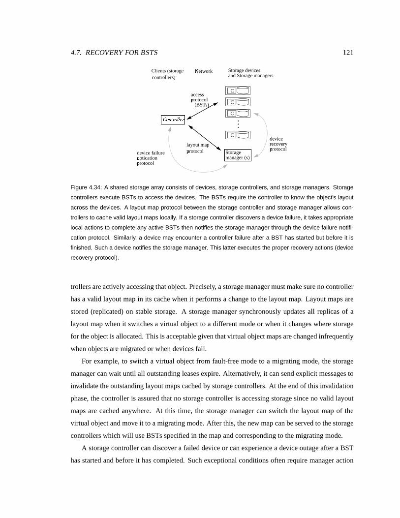
4.7. RECOVERY FORBSTS 121
. .
C
C
C
C
.
Storage devices
CEDGFIH JKDML L NOJ
Storage manager (s)
access pP rotocol (BST s)
layout map pP rotocol
Clients (storage controllers)
NQ
etwork and Storage managers
device failure
device recovery pP rotocol
nR otication pP rotocol
Figure 4.34: A shared storage array consists of devices, storage controllers, and storage managers. Storage
controllers execute BSTs to access the devices. The BSTs require the controller to know the object’s layout
across the devices. A layout map protocol between the storage controller and storage manager allows con-
trollers to cache valid layout maps locally. If a storage controller discovers a device failure, it takes appropriate
local actions to complete any active BSTs then notifies the storage manager through the device failure notifi-
cation protocol. Similarly, a device may encounter a controller failure after a BST has started but before it is
finished. Such a device notifies the storage manager. This latter executes the proper recovery actions (device
recovery protocol).
trollersareactively accessingthat object. Precisely, astoragemanager mustmakesurenocontroller
has a valid layout map in its cachewhen it performsa change to thelayout map. Layout mapsare
stored (replicated) on stable storage. A storagemanager synchronously updatesall replicasof a
layout map whenit switchesa virtual object to a different mode or whenit changeswhere storage
for theobject is allocated.This is acceptable giventhatvirtual object mapsarechanged infrequently
whenobjectsaremigratedor whendevicesfail.
For example, to switch a virtual object from fault-f reemode to a migrating mode, thestorage
manager canwait until all outstanding leasesexpire. Alternatively, it can send explicit messagesto
invalidatetheoutstanding layout mapscachedby storagecontrollers. At theendof this invalidation
phase, thecontroller is assured that no storage controller is accessing storage since no valid layout
mapsarecached anywhere. At this time, the storage manager can switch the layout mapof the
virtual object and move it to amigrating mode. After this, thenew mapcanbeservedto thestorage
controllerswhich wil l useBSTsspecified in themapandcorresponding to themigrating mode.
A storage controller candiscover a failed device or can experiencea device outageafter a BST
has started and before it has completed. Such exceptional conditions oftenrequire manager action

122 CHAPTER 4. SHARED STORAGE ARRAYS
ISnactive Blocking
rT st phase UWV XZY [\V+] ^ XD_
one
rT eceived, ACCEPT sent back to controller
rst phase request received, REJECT sent back to controller
second phase [\VK] ^ Xreceived, storage
R`
ecovering
Storage manger na otied, recovery algorithm completed
Ub
pdated
uc pdated ACK reply sent bd
ack to controller
teime-out period
ef xpires while ign Blocking state
Second phase hji(k(hjXMlreceived
1 2
1
2
Figure 4.35: The states of a device during the processing of a BST. The device starts in the Inactive state.
The transition to the Blocking state occurs with the receipt and the successful processing of a first phase
prewrite request from a storage controller. If a second phase write message is received confirming the prewrite,
the device updates storage and transitions to the Updated state. A reply is sent to the controller and a final
transition to the Donestate from the Updated state is performed. If the second phase message is a cancel, the
device discards the prewrite and transitions to the Done state. If a time-out period passes while the device is
in the Blocking state and without the receipt of any message, the device transitions to the Recovering state.
The arrows labeled with a “1” (“2”) refer to transitions that are caused by the receipt and processing of a first
(second) phase message from the controller.
to restore consistency and properly complete theBST. A controller-managerprotocol allows con-
trollersto report such failure conditions to thestoragemanager(Figure 4.34). Similarly, a storage
device can block in the middle of executing a BST waiting for a controller messagethat never ar-
rives. The controller mayhave failed or restartedand lost all its state asa result. In this case, the
device must notify the storage manager to properly completethe BST and ensure consistency. A
device-managerprotocol (Figure4.34) is definedto allow devicesto report incompleteBSTs to the
storagemanager.
4.7.2 An overview of recovery for BSTs
Thediscussion assumesthat all storage manager failuresand network failuresaremasked, leaving
four remaining kinds of failuresof interest: device failures, deviceoutages, controller failuresand
controller outages. The amount of work required to recover properly from a failure or outage de-
pends largely on whentheeventoccurs. Figure4.35shows thestatesof adevice involved in aBST.
Thedevice starts in the Inactive state. This discussion assumesa timestampordering protocol, but

4.7. RECOVERY FORBSTS 123
the case of device-servedlocking is quite similar. Both protocols essentially export a lock to the
datablockafter thefirstphaserequest isacceptedat thedevice. Thisexclusive lock is releasedonly
after the second phase message is received. In the Inactive state, the device receives a first phase
request,a prewrite or a read-and-prewrite request. If therequest is rejected, a reply is sent backto
the controller and theoperation completesat thedevice and the device moves to theDone state. A
new operation mustbe initiated by thecontroller to retry theBST.
If the request is accepted, the device transitions to the Blocking state. In this state, the block
is locked and no access is allowed to it until a second phase message is received. The second
phase message can be a cancel message or a write message containing the new contents of the
block. If a cancel messageis received, thedevice discardstheprewrite and transitions to the Done
state. If a write message is receivedconfirming the prewrite, thedevice transitionsto the Updated
stateoncethedata is transferredsuccessfully to stable storage. The device thenformulatesa reply
acknowledging thesuccessof thewriteand sendsit to thecontroller. Oncethemessageis sent out,
thedevice transitions to theDonestateand theBST completes.
If atime-out period passesandnosecond phasemessageis received, thedevicetransitionsto the
Recovering state. From this state, the devicenotifies the storage managerof the incompleteBST
and awaits the manager’s actions. The manager restores the array’s consistency before allowing
the device to resumeservicing requeststo thevirtual object. Similarly, if thedevice experiencesa
failure in themidst of processing a write messagesuch that storage is partially updated, the device
transitionsto theRecovering stateandnotifies thestoragemanager.
Figure 4.37 shows the statesof a controller executing a BST. The figure shows a write BST.
In the first phase, prewrite messages possibly combined with reads are sentout. Thesemessages,
markedwith a “1” in Figure 4.35, causethedevice to transition from the Inactive to theBlocking
stateif theprewrite is acceptedor to theDonestateif theprewrite is rejected. Onceall therepliesto
thesefirst phase messages are collected by the controller, a second phaseround of message is sent
out to confirm the write or to cancel it. Thesemessages,markedby a “2” in Figure 4.35, causethe
device to transition from Blocking to Done (in caseof a cancel) or from Blocking to Updated (in
caseof asuccessfully processed write).
The statediagram of Figure 4.35 is helpful in understanding the implications of a device or
controller failure or outagewhile a BST is in progress. A controller failure or outage before any
phase 1 messagesare sent out is benign, that is, it doesnot require the involvement of thestorage
manager to ensure recovery. Recovery can beachievedby local actions at the nodes. In this case,

124 CHAPTER 4. SHARED STORAGE ARRAYS
Fm
ault-Free
Rn
econstructing Degraded
Uo
navailable
Data loss
pp ermanent device failure
(active)
replacement allocated
pp ermanent device failure cq ritical controller/device outage
cq ritical device outage cq ritical controller outage
rr ecovery completed
pp ermanent device failure cq ritical controller/device outage
bs
enign device/controller outage
bs
enign dt
evice/controller ou utage
pp ermanent device failure
bs
enign dt
evice/controller ou utage
bs
enign device ou r controller outage
rr econstruction completed
Figure 4.36: The modes of a virtual object and the events that trigger modal transitions. Benign failures and
outages do not cause the object to switch modes. Critical device outages, device failures, and critical controller
failures and outages cause the object to switch modes. A second critical failure while the object is in degraded,
reconstructing or recovering modes is catastrophic and results in data unavailability.
upon restart, thecontroller must simply re-fetch the layout maps to begin accessto storage. In this
case,nodevicehastransitionedto theBlocking stateandnolocksareheldby theBST. If acontroller
experiencesa failure or outage after all the second phasemessagesare sent out and successfully
received by the devices, then thedeviceswill update theblocks on persistentstorageand complete
theBST. Thedeviceswill transition from theBlocking to theUpdatedand unilaterally to theDone
state. Such a failure is also benign. However, a controller failure or outageafter at least onedevice
has transitioned to theBlocking state andbeforeall the second phase messages are sent out to the
devicesis considered critical; that is, will require special action by the storagemanager to restore
thearray’sconsistency and/or to ensureprogress.
Similarly, a device failure or outage before any device has reached the Updated state can be
handled easily by thecontroller. Since no storagehas beenupdatedanywhere, a storagecontroller
facing apermanent devicefailureor adeviceoutage(inaccessibledevice) can simply abort theBST
by multicasting acancel messagein thesecondphaseto all thesurviving devices.Thedevicefailure
or outagecan beconsidered to haveoccurred beforetheBSTstarted. Thestoragecontroller notifies
thestoragemanager of theproblemand thestoragemanager movestheobject to thepropermode.
However, if a device failure or outage occurs after some devices have received and processed

4.7. RECOVERY FORBSTS 125
thesecond phasemessageandtransitionedfromtheBlocking to Updatedstate,recovery is slightly
morecomplicated. Thestoragecontroller completesthesecondphaseby writing to all thesurviving
devices.This failureis consideredcritical becauseit requiresspecial action by thestoragemanager
on recovery. The managermust establish whether thedevice haspermanently failed or has expe-
rienced an outage (restart). If the device haspermanently failed, the failure can be considered to
have occurredright after the device wasupdated. TheBST is considered to havesucceededbut the
virtual object must bemovedto adegraded modeand reconstruction on a replacement device must
besoon started. If the device has experiencedanoutage, the device should not be madeaccessible
immediately upon restart sinceit still containstheold contents of theblocks. Thestorage manager
mustensure that the datathat the BST intended to write to the device is on stable storage before
re-enabling access. This datacanbe reconstructedfrom theredundant copywrittenby theBST.
A virtual object canbe in oneof several modes: Fault-Free,Migrating, Degraded, Reconstruct-
ing, Unavailable or Data-loss.Thefirst four modeswerealready introduced. The lasttwo were not
becausethey do not pertain to theconcurrency control discussion. In thelasttwo states(Unavailable
and Data-loss),hostaccessesto thevirtual object arenot allowed. In theData-lossmode, theobject
is not accessible at all. In the Unavailable mode, the storagemanager is theonly entity which can
access theobject. In thismode,thestoragemanager restores theconsistency of thearray. Oncethe
array is consistent, the manager movesthe object to an accessmode andre-enables access to the
object.
Figure 4.36 represents a sketch of the different modes of a virtual object. The object starts
out in Fault-Free mode. A permanent device failure causes a transition to the Degraded mode.
The allocation of a replacement device inducesa transition to the Reconstructing mode from the
Degradedmode. A second device failureor a critical outage (of a device or controller in the midst
of a BST) while theobject is in degradedor reconstructing modesresults in dataloss. The object
transitionsto theData-lossmodeand itsdata isno longeravailable. Critical outagesof controlleror
device while the object is in Fault-Free mode cause a transition to theUnavailable modewhere the
object is not accessible until thearray’s consistency is restored. In this mode,no storagecontroller
can accessthe object because no new leasesare issued and previous leases have expired. The
storage manager consults a table of actions which specifies what recovery procedure to take for
each kind of failure andBST. A compensating BST is executed to achieve parity consistency, the
object is potentially switched to a new mode, and then new leasescan be issued. Benign failures
and outages,on the other hand, do not causetheobject to changemodes. They do not require any

126 CHAPTER 4. SHARED STORAGE ARRAYS
recovery work besidespossibly a localactionby thenodeexperiencing theoutageupon restart.
4.7.3 Recovery in fault- fr eeand migrati ng modes
Under Fault-Free and Migrating modes,all devicesareoperational. The discussion wil l focus on a
single failureor outage occurring at a time. The pseudo-code executed by thedevicesis given in
Section 4.7.6.
Controller outage/failure. Controller failures and outagesareessentially similar. A permanent
controller failure can beregardedas a long outage. Because a storage controller losesall its state
during anoutage, it makesnodifferenceto thestoragesystem whether thecontroller restartsor not.
Any recovery work required to restorethearray’sconsistency mustproceedwithout theassistanceof
thefailed storagecontroller. A controller outageamountsto losing all the layout mapscachedat the
client. After restart, thestoragecontroller must re-fetch new layout mapsfrom thestoragemanager
to accessvirtualobjects. Uponrestart, no special recovery work is performedby thecontroller.
When thevirtual object is in Fault-Free/Migrating modeand the storage controller experiences
anoutagewhileno BSTsareactive,theoutage isbenign. Thevirtual object doesnot changemodes
asa result of thecontroller failureor outage. Upon restart of the storage controller, accessto the
virtual object can begin immediately.
Critical controller failuresand outages canoccur in the midst of a BST’s execution. Thecon-
troller can crashafter some deviceshave accepted its prewrite request. These deviceswill move
to the Blocking stateand wait for a second-phasemessage. This second phasemessage will never
comebecausethecontroller hascrashed. A storagedeviceassociatesa time-out with eachaccepted
prewrite request. If thecorresponding second phasemessage(cancel or write) is not received within
the timeout period, thestoragemanager is notified.
The storage manager mustrestore the consistency of the array becauseit may have been cor-
rupted asa result of the controller updating somebut not all of thedevices. Thestoragemanager
restoresthe consistency by recomputing parity. The storage manager does not guarantee that the
dataon thedevicesreflect thedatathecontroller intendedto write. To completethewrite,theappli-
cation mustre-submit thewrite. This is correct sincethesemantics of a hostwrite, like a write to a
diskdrive today, is not guaranteed to havecompletedand reached stablestorageuntil thecontroller
responds with a positive reply. In this case,the controller did not survive until theend of theBST
and could not have respondedto theapplicationwith apositivecompletion reply.
Deviceoutage.A device outage whenthedeviceis in the Inactive state doesnot require much

4.7. RECOVERY FORBSTS 127
PW PW PW
Wv
Wv
Wv
Cw
ommit
Roll-back BST ,x retry using a (possibly dif ferent) BST
Ry
oll-forward BST ,x complete all the writes that can be completed
1
2
1 r ez plies
2 r ez plies
P{
W P{
W P{
W
C|
an C|
an C|
an
A}
bort
1
2
1 r~ ez plies
2 r~ ez plies
I�nactive Inactive
D�
one Done
Figure 4.37: The algorithm followed by the controller when executing a BST. Ovals correspond to the state of
the BST at the controller. Circles correspond to the processing of a message at the device. An arrow from an
oval to a circle is a message from a controller to the device. An arrow from a circle to an oval is a reply from the
device to the controller. The controller starts in the inactive state, issues a first round of prewrite messages,
and once the replies are collected decides to commit or abort the BST. Once a decision is reached, second
phase messages are sent out to the devices. Once the replies are received, the BST completes. The point
right before sending out second phase write messages is called the commit point. The controller experiencing
a device failure or outage before the commit point decides to Abort the BST. If all devices accept the prewrite,
the BST is committed and writes are sent out to the devices that remain available. All failures in the second
phase are simply reported to the storage manager.
recovery work besidescareful initialization proceduresupon restart from theoutage. Under times-
tamp ordering, thedevicemustwait period of � secondsuponrestartbeforestarting to servicenew
requests. Thedevicecanestablish thatno BSTs werein progressduring theoutage by inspecting
its queueof accepted prewrites stored in NVRAM. If the queueis empty, the device waits for �seconds and starts accepting requests. If the queue contains some entries, the device enters the
Recovering modeand notifies thestoragemanager.
Notice that all BSTs usedin a sharedstorage array are representedas directed acyclic graphs
(Figure4.37), in which it is possible to ensure that nodevicewritebeginsuntil afterall devicereads
are complete [Courtright, 1997]. This point, right before the storagecontroller sends out second
phasewrite requestsis called thecommit point. A storagecontroller may encounteradeviceoutage
before the commit point, that is before any second phase messagesaresent out. In this case,the
storage controller notifies the storage manager that it suspects a device failure, after canceling its
firstphaserequestsat theotherdevicesthat have responded to it during thefirst phase. In any case,
recovery is simply enacted by retrying the BST later when the device is back on-line. No special
recovery work is requiredat thedeviceor storagemanager.

128 CHAPTER 4. SHARED STORAGE ARRAYS
If the storage controller hascrossedthe commit point but did not complete the writesevery-
where,then thesurviving deviceswill updatestorage(moveto theUpdated andDonestates) while
the device experiencing theoutage will not. This device hasacceptedtheprewrite but is not avail-
able to processthecorresponding write. In this case,recovery proceedsas follows. Upon restart,
thedeviceinspects its queueof acceptedprewritesstoredin NVRAM and discoversthat it hasfailed
afteraccepting aprewrite andbeforeprocessing thecorresponding write. Suchadevicenotifies the
storagemanager to perform recovery.
Devicefailure.A permanent device failurecan occur (or bediscovered) when thesystem is idle
or whenaBST is active. If thefailureoccursduringan idle period, thestoragemanager is notified.
The storage manager revokesall leases to the virtual objects that have been allocated storage on
that device. The virtual objects are moved to the degraded or reconstructing mode, marking the
deviceasfailed.Theobject is moved to areconstructing modeif thestoragemanager can reallocate
storagespaceona functional device to replace thespaceon thefaileddevice.Giventhatthedevice
is no longer available, datastored on thedevice must be reconstructedfrom redundantcopies.The
storage manager changes the layout map to reflect the new allocation andmoves the object to a
reconstructing mode. A task to reconstruct the contents of the failed device and write it to the
replacement space is started. If there is no spaceavailable to allocate asa replacement, the object
is moved to a degradedmode. In degradedmode, writesaddressedto the failed deviceare reflected
in the parity. In any case, storage controllers that fetch the new map wil l be required to usethe
degradedmodeor thereconstructingmodeBSTs asspecified in themap.
A permanent device failurecanalso bediscoveredafter aBSThasstarted. In thiscase, thestor-
age controller must becareful in how to completetheBST. Before reaching the commit point, any
BST encountering a permanent device failure (during a read) simply terminates, and its parent task
reissuesa new BST in degradedmode. This occursasfollows. The storagecontroller discovering
the permanent failure aborts the current BST, discardsthecurrent layout mapandnotifies thestor-
age manager of thefailure. Thestoragemanager verifies that thedevicehasfailed andthenmoves
the virtual objectsto degraded or reconstructing mode. Thestorage controller fetchesthenew map
and restarts theaccessusing adegradedmodeBST.
After the commit point, a BST canencounter a permanent device failure. A storagecontroller
encountering a single device failure after one or more writes aresent to the devicessimply com-
pletes. This is correct because an observer cannot distinguish betweena single failure occurring
after the commit point and the failure of that device immediately after the BST completes. The

4.7. RECOVERY FORBSTS 129
recovery protocol proceeds as follows. After the write completes, thestorage manager is notified
of the failed device. Thestoragemanager movestheobject to a degradedor reconstructing mode
before re-enabling accessto theobject.
Leaseexpiration. A storage controller can experiencea special kind of outage dueto theexpi-
ration of a lease. Note thata leasecanexpire whentheclient is in themiddleof executing aBST. If
theexpiration occursbeforethecommitpoint, thenthesecondphaseis not started. Instead, requests
are sent to the devices to cancel the first phaseand releasethelocks. The map is thenrefreshedby
contacting theappropriate storagemanager effectively extending the lease. Theaccess protocol at
the storage controller checksthe leaseexpiration time before starting thesecond phase to establish
that the leasewill remain valid for theduration of thesecondphase.Becauseall lock requestshave
beenacquiredin thefirst phase,thesecondphasewill not lastfor a longtime. Onceall replieshave
beenreceivedfromthedevices, theBST is consideredto havecompletedsuccessfully.
A storagemanager may enter an object into a recovery mode during this second phase. This
occurs if the second phase lasts for a long enough time that the leaseexpires. Since no client
accessesareaccepted in recovery mode and all locks are reset, the storagedevice will respond to
thecontroller’ssecondphasemessagewith aerror code. TheBST isconsideredfailedby thestorage
controller andthe write must be retried to make sure that the contents of storage reflectthevalues
in thewritebuffer.
4.7.4 Recovery in degradedand reconstructing modes
Under this mode, a device has failed in the array and therefore the array is not fault-tolerant. A
second device failureor an untimely outagecan result in data loss.
Controller outage/failure.As in theFault-FreeandMigratingmodes, acontroller outageamounts
to losing all the layout maps cached at theclient. After restart, thestoragecontroller mustre-fetch
new layout maps from the storage manager to accessvirtual objects. Benign failures that occur
whenno BST is active or in the issuing stateof a BST are straightforwardto handle. Upon restart
of thecrashedcontroller, accesscanbegin immediately also.
Controller failures and outagesthat occur in the midst of a BST can often lead to data loss
becausethey corrupt the parity code making the dataon the faileddevice irreconstructible. If the
outageoccursbefore thecommitpoint but after somedeviceshavereachedtheBlocking state,then
no devicehas been updated. Thedeviceswill eventually time-out and notify thestoragemanager.
The storage manager, however, may not be able to ascertain whether thecontroller did or did not

130 CHAPTER 4. SHARED STORAGE ARRAYS
crossthecommit point and must in this caseassumethe controller may have partially updated the
stripeand consequently declaredataloss. Under a few fortunatecases, thestoragemanager will be
able to establish thatnodevicehasbeenupdatedand cancel (roll-back) theBST without moving the
object to theData-lossstate.
If the storage manager finds that all the devicesparticipating in the BST started by the failed
controller are in the Blocking state, then it can concludethat no device hasupdated storage. In
this case,thestoragemanager can cancel theprewritesand re-enable accessto theobject. If on the
other hand, thestoragemanagerfindsthat at leastonedevicehasaccepted aprewrite or write with a
higher timestampthan that of theincompleteBST, it cannot establishwhether that devicerejected
the prewrite of the incomplete BST or whether it accepted it. It is possible that this device has
accepted theprewrite. Thestoragecontroller could havesent awritemessageto thedeviceand then
crashedbeforeupdating theremaining devices. In thiscase,thedevice would haveupdatedstorage
and completed theBST locally. It could have later acceptedanotherprewriteor write with a higher
timestamp. In this case, the storagemanager must assumethe conservative option and declare that
theBST updated somedevicesbut not all of them declaringdataloss.
In order for the storagemanager to accurately determine the fateof the incompleteBST at all
the devices, it must have accessto thehistory of writesserviced in the past. This canbe achieved
if the device maintains in NVRAM not only the accepted prewritesbut also the recently serviced
writes to theblock.
Deviceoutage.A critical device outageoccurs whena deviceparticipatesin thefirst phaseof
a BST and then experiences an outage before receiving the second phasemessage. In this case,
recovery depends on when the outage is discovered. If the outage occurs during the Issuing or
Blocked states, the storage controller will fail to contact the device and will therefore cancel the
requestsaccepted at theotherdevicesand inform thestoragemanager of thedevice’sinaccessibili ty.
In this case, theaccessis simply retried later whenthedevice is back on-line. No special recovery
work is requiredat thedevice or storagemanager.
If the storage controller haswritten to the storagedevicesit intended to update except for a
device that experienced the outage after responding to the first phase message, then the storage
controller completesthe write to thesurviving devices andwritesthe dataintended for the crashed
device to a designatedscratch space. Then, it notifies the storage manager. The storage manager
revokesall leasesand movesthe objectto the recovery mode. Whenthe device restarts, the data is
copiedfromthescratch spaceto thedeviceand accessis re-enabled. If theoutagewasexperienced
4.7. RECOVERY FORBSTS 131
by thereplacement device,thenthe incomplete BST is compensatedfor by copying thedata which
wassuccessfully writtento thedegraded array to thereplacement device. In this case,thecontroller
neednot write to ascratchspacesinceit is already storedin thedegradedarray.
Device failure.A permanent device failure in degraded modeamounts to data loss. Theobject
is moved to theUnavailable modeandits dataisno longeraccessible.
4.7.5 Storagemanageractionsin the recovering mode
The storagemanager receives notifications of device outages and failures from controllers. The
storagemanagertakesasimple sequenceof actionsuponthereceipt of suchnotifications. It revokes
all leasesfor thevirtual objectbeing updated, thenexecutestheproper compensating BST to restore
thearray’sconsistency then movestheobjectto adifferent modeif necessary andfinally re-enables
access to thevirtual object.
Upon ageneral power failure,all thedevicesand clientsexperiencea transient failureandmust
restart fresh,losing all thestate in their volatile memory. In thiscase, there is no surviving entity to
notify thestoragemanagerof theoutage.All thedevicesandcontrollersexperienceasimultaneous
outage. Controllers have no state and upon restart can not assist the storage manager in restoring
the array’s consistency. They cannot tell thestorage manager what BSTs werein progressduring
theoutage.
Thestoragemanagerreliesonthedevicesto efficiently perform recovery afterageneral outage.
Upon a restart, a device notifies the storagemanager(s) that allocated space on it so that storage
managers can carry out any recovery work before the device is allowed to start servicing client
requests. The storage manager must determine whether and which nodes experienced a critical
outage; thatis,wereactively processing aBST during theoutage. This isachievedasfollows. Upon
restart from anoutage, a storagedevice inspects its queue of accepted prewrites. This information
is stored in NVRAM on the device and therefore survives transient outages. If the queues are
found empty, thedevice is madeaccessible to serve requests to thestoragecontrollers. If thequeue
contains outstanding prewrites, thenthestorage manager knows that a BST wasin progressduring
theoutage. It canthenexecute thepropercompensating action.
Table4.5summarizestherecovery actionstakenby thestoragemanageruponacriticaloutageor
failure. Thetable shows thecompensating transactionexecuted by thestoragemanager to complete
theBST to achieveconsistency. It also shows thenew mode that theobjectwil l transition to ( from
theUnavailablemode) after recovery is completed.
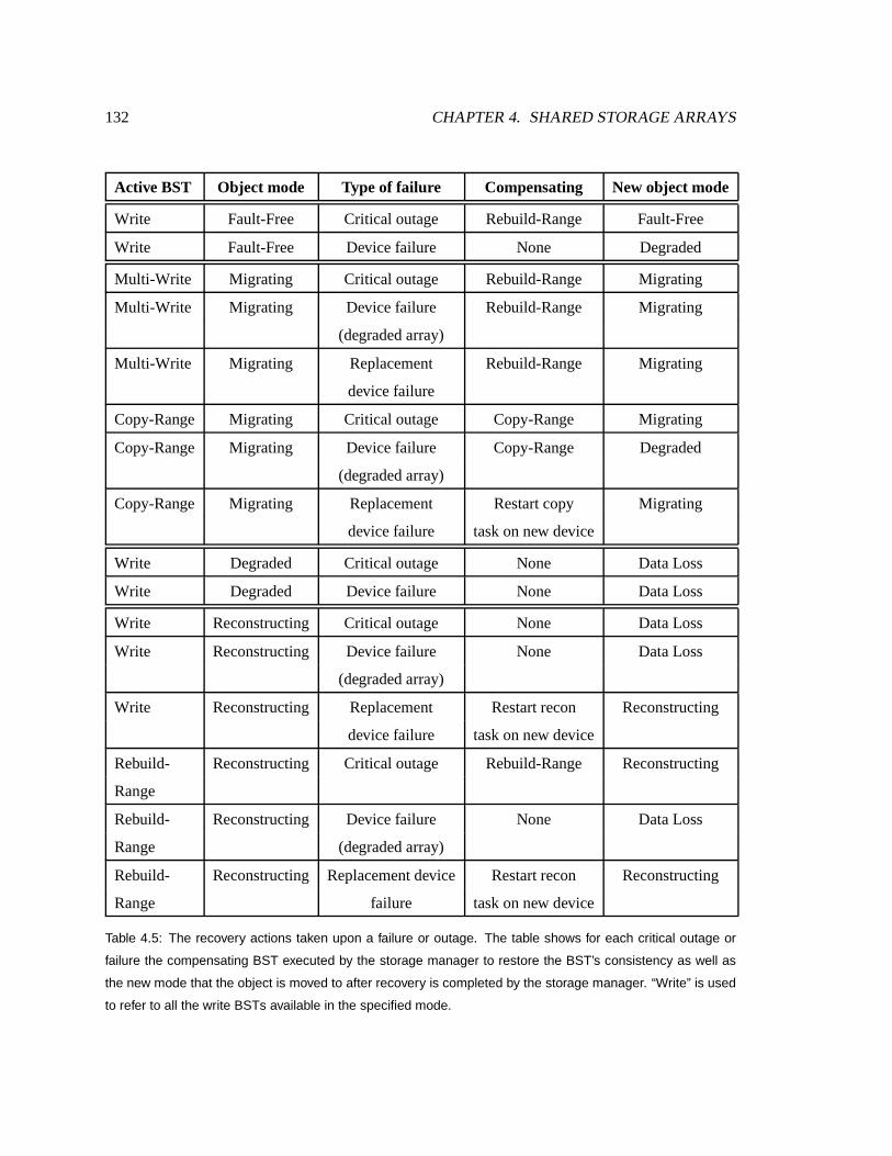
132 CHAPTER 4. SHARED STORAGE ARRAYS
ActiveBST Object mode Typeof failur e Compensating Newobjectmode
Write Fault-Free Critical outage Rebuild-Range Fault-Free
Write Fault-Free Devicefailure None Degraded
Multi-Write Migrating Critical outage Rebuild-Range Migrating
Multi-Write Migrating Devicefailure Rebuild-Range Migrating
(degradedarray)
Multi-Write Migrating Replacement Rebuild-Range Migrating
devicefailure
Copy-Range Migrating Critical outage Copy-Range Migrating
Copy-Range Migrating Devicefailure Copy-Range Degraded
(degradedarray)
Copy-Range Migrating Replacement Restart copy Migrating
devicefailure taskonnew device
Write Degraded Critical outage None DataLoss
Write Degraded Devicefailure None DataLoss
Write Reconstructing Critical outage None DataLoss
Write Reconstructing Devicefailure None DataLoss
(degradedarray)
Write Reconstructing Replacement Restart recon Reconstructing
devicefailure taskonnew device
Rebuild- Reconstructing Critical outage Rebuild-Range Reconstructing
Range
Rebuild- Reconstructing Devicefailure None DataLoss
Range (degradedarray)
Rebuild- Reconstructing Replacementdevice Restart recon Reconstructing
Range failure taskonnew device
Table 4.5: The recovery actions taken upon a failure or outage. The table shows for each critical outage or
failure the compensating BST executed by the storage manager to restore the BST’s consistency as well as
the new mode that the object is moved to after recovery is completed by the storage manager. “Write” is used
to refer to all the write BSTs available in the specified mode.

4.7. RECOVERY FORBSTS 133
Compensating storage transactions in degraded and reconstructing modes
In degraded mode, one of the data disks has already failed. A second disk or client failure in
the middle of an access task before the dataon the first disk is reconstructed is considered fatal.
Similarly, in the reconstructing mode, one of the data disks has already failed. A second disk or
client failure in the middle of an accesstaskbefore the dataon the first disk is reconstructed is
considered fatal. However, if the failure occurs in the middle of a reconstruct task (the Rebuild-
Range BST), then the BST can be simply restarted. The degraded array is not corrupted by the
failure, although the replacement block being written to may have been only partially updated.
The BST can be restarted and the value of the failed data block recomputed and written to the
replacement device.
Compensating transactionsin Fault-Fr eeand Migrating modes
Oncethe failed BST is detected andreported to the storage manager, the storage manager waits
until all leases to the virtual object expire andthen executes a compensating transaction to restore
the array’s consistency. Onceconsistency is restored, the mode of the virtual object is updated if
necessary andaccessre-enabled by granting layout maps to the requesting controllers. Each BST
has a compensating BST which is executedexclusively by thestorage manager in recovery mode
wheneveraBST fails.
Under fault-f reemode, once the suspect ranges are identified, consistency can be effectively
re-establishedby recomputing theparity block from thestripe of data blocks. Under this mode, all
devicesareoperational, so theRebuild-RangeBST canbeusedto recompute theparity block.
In migratingmode, aBST is invokedeitherby anaccesstask or by amigratetask. For BSTsthat
are invoked by hostwrite tasks, the compensating transactionsare similar to the onesin Fault-Free
mode. In the caseof a copyBST that is invokedby a migrate task, thecompensating transaction is
the transaction itself. Thatis, thestoragemanagersimply reissuesthecopy transaction.
4.7.6 The recovery protocols
This section presents thepseudo-codefor the actions takenby thedevices and storage controllers.
Storage controllers are relatively simpler. They arestateless,do not have to execute any special
algorithms on restart or recovery from an outage. The important task implementedby the storage
controller is the execution of a BST. Thepseudo-codeon the following pageshows the algorithm
abstracting the details of the concurrency control algorithm andfocusing on the recovery actions

134 CHAPTER 4. SHARED STORAGE ARRAYS
taken by thecontrollerwhile in themidstof executing aBST. Thestoragecontroller canexperience
a device outage or failure of simply a device that is not responding. Upon encountering such an
event, the storage controller cancels the BST if it did not cross the commit point. Otherwise, it
completestheBST. As soon as theBST is completed or canceled, thestoragecontroller reports the
problemto thestoragemanagerwhich in turns takestherecoveryactionsdescribed above.
Storagedevicesaremorecomplicated,becausethey maintain stateacrossoutagesand restartsof
controllersand of their own. Upon recovery, storagedevicesexecutethefunction InitUponRestart().
During normal operation, requestsarehandled by invoking the HandleRequest function. If a time-
out is reachedwhileasecondphasemessageisnotreceived, theHandleTimeoutfunction is invoked.
Thepseudo-codereflectsthestepsalready discussedfor device recovery and time-out handling.
//Device Actions
01 /* Device-side pseudo-code: Handle request req from controller contr */
02 HandleRequest (req, contr)
03 if ( req.type == read)
04 resp = checktimestamp(req.opts, req.blockid);
05 if (resp==OK)
06 send (data[req.blockid], OK) to contr;
07 else
08 send (REJECT) to contr;
09 endif
10 if ( req.type == prewrite or read-and-prewrite)
11 resp = checktimestamp(req.opts, req.blockid);
12 if (resp == OK)
13 enqueue (req, NOW + TIMEOUT) to timeoutq;
14 send (OK, data) to contr;
15 else
16 send (REJECT) to contr;
17 endif
18 endif
19 if ( req.type == write)
20 /* discard request with timestamp opts from queue */
21 write req.buf to req.blockid on stable storage;
22 timeoutq.discard(req.opts);
23 send (OK) to contr;
24 endif

4.7. RECOVERY FORBSTS 135
01 /* Device-side pseudo-code to handle a timeout */
02 HandleTimeout (req)
03 send (req, BST_NOT_COMPLETED) to storage manager;
04 end
01 /* Device-side pseudo-code to execute after restart from an outage */
02 InitUponRestart()
03 if (prewriteq is empty)
04 wait T seconds;
05 return (OK); /* upon return, requests can be accepted */
06 else
07 send(NULL, BST_NOT_COMPLETED) to storage manager
08 return (RECOVERING);
09 endif
10 end
// Controller actions
01 /* Execute a two phase write bst to object with map objmap */
02 ExecuteTwoPhaseBST (bst, objmap)
03 for dev = 1 to bst.numdevices
04 send (bst.device[i]);
05 endfor
06 deadline = NOW + TIMEOUT;
07 while ( replies < numdevices and time < deadline)
08 receive(resp);
09 replies ++;
10 endwhile /* continued on next page ...*/

136 CHAPTER 4. SHARED STORAGE ARRAYS
11 if (replies < numdevices)
12 /* some devices did not respond */
13 for dev = 1 to bst.numdevices
14 send (CANCEL) to bst.device[i];
15 endfor;
16 /* notify manager of the not-responding devices */
17 for each dev not in replies
18 send (dev, NOT_RESPONDING) to storage manager;
19 endfor;
20 Discard(objmap); /* discard layout map, must be re-fetched later */
21 return (DEVICE_OUTAGE_OR_FAILURE);
22 else if (numoks in replies < numdevices)
23 /* rejection at one or more devices, send CANCELs */
24 for dev = 1 to bst.numdevices
26 send (CANCEL) to bst.device[i];
26 endfor;
27 return (RETRY);
28 else if (numoks in replies == numdevices)
29 for dev = 1 to bst.numdevices
30 send (OK, bst.data[i] to bst.device[i])
31 endfor
32 replies = 0; deadline = NOW + TIMEOUT;
33 while (replies < numdevices and time < deadline)
34 receive (resp);
35 endwhile
36 if (replies < numdevices) /* some devices did not respond */
38 slist = null; /* list of devices suspected of failure */
37 for dev = 1 to bst.numdevices
38 if (dev did not respond)
39 add dev to slist;
40 /* notify manager of the not-responding devices */
42 send (bst, BST_NOT_COMPLETED, slist) to storage manager;
44 Discard(objmap);
45 return (DEVICE_OUTAGE_OR_FAILURE);
46 endif
47 endif

4.8. DISCUSSION 137
4.8 Discussion
The discussion so far focussed on protocols that ensure serializability for all executing BSTs.Seri-
alizability is a “sufficient” guarantee sinceit makesa sharedarray behave like a centralizedone,in
which asinglecontroller receivesBSTsfromall clientsand executes them oneata time. This guar-
antee, however, canbe too strong if certain assumptionshold regarding thesemanticsand structure
of high-level software. Furthermore, thediscussion hasfocussedonRAID level 5 layouts. However,
a largenumberof disk arrayarchitectureshavebeenproposedin theliterature.
Thissectionhighlightsthegenerality of thepresentedprotocolsby showinghow they can readily
generalizedto adapt to and exploit different application semantics and underlying data layouts. It
alsoincludesadiscussion of the recovery protocols.
4.8.1 Relaxing read semantics
Many applicationsdo not sendaconcurrent hostreadandhostwrite to thesameblock. For example,
many filesystemssuch asthe Unix Fast File System [McKusick etal., 1996], do not send a write
to thestorage system unlessan exclusive lock is acquired to that block, which prohibits any other
client or thread from initiating areador write to thatblock until thewrite completes. Consequently,
it neveroccurs thata readis initiatedwhile awrite is in progressto thatblock.
This property of many applications precludes the need to ensure the serializabilit y of reads
becausethey neveroccur concurrently with writes. In fault-freeoperation, where readsdo notneed
to accessparity blocks,ahostreadaccessesonly datablocks thehigherlevel filesystemhasalready
acquired (filesystem-level) locks for. It follows that the only concurrent writes to the samestripe
mustbeupdating other data blocks besidesthe ones being accessedby thehostread. It is therefore
unnecessary to acquirea lock to thedatablock beforea read.
Recall that in fault-free mode, only hostread and hostwrite tasks are allowed. Thus, if the
higher-level filesystemensuresnoread/writeconflicts, hostreadscan simply bemapped onto direct
devreadswith no timestamp checksor lockacquire/releasework. This canspeed up theprocessing
at thedevicesand reducetheamount of messaging on thenetwork. Note that this readoptimization
can not be applied in degraded mode. Serializabili ty checking is required in degraded mode and
reconstructing modesbecausecontention can occur over the samedata block even if thehosts do
not issueconcurrent hostread and hostwrites to thesameblock. Theperformanceevaluation results
and conclusions do not change much even if concurrency control is not performed on fault-free
modereads. In this case,all theprotocolswill not performany control messaging onbehalf of reads

138 CHAPTER 4. SHARED STORAGE ARRAYS
and thereforehave theminimal latency possible for hostreads. Concurrency control isstil l required
for hostwriteswhichcanconflict onparity aswell asdatablocks.
Note that regardlessof what the higher-level software is doing, concurrency control mustbe
ensured for two concurrentwritesto the same stripe. This is becausetwo writesto different data
blockscan contendover thesamedataor parity blocks, something that is totally invisible to higher-
level software (consider, for example, a Read-Modify-Write BST and a Reconstruct-Write BST,
both shown in Figure 4.5, occurring concurrently in Fault-freemode). Serializability of such write
BSTs is essential so that parity is not corrupted. Similarly, the serializabili ty of copy BSTs with
ongoing writesis also requiredfor correctnessregardlessof what thesynchronization protocol used
by higher-level software.
Finally, thedeadlock problem associated with device-served locking variantscan beeliminated
by requiring clients to acquire locks on entire stripes. This breaks the “hold and wait” condition
becauseclients do not have to acquire multiple locks per stripe. Only a single lock is acquired.
Stripe locking substantially reduces concurrency, however, especially with largestripe sizes. This
in turn degradesI/O throughput and increasesaccesslatenciesfor applicationsthat perform a lot of
small writes to sharedlargestripes.
4.8.2 Extension to other RAID levels
Theapproachdiscussedin thischapter can beextendedin astraightforwardmannerto otherRAID
levels, including double-fault tolerating architectures. The reason is that all the readand write
operations in all of the RAID architectures known to the author at the time of the writing of this
dissertation [Blaum etal., 1994, Hollandet al., 1994] consisteitherof asingle(reador write) phase
or of a read phase followed by a write phase. Thus, the piggy-backing and timestampvalidation
approach described in theprevioussectionsapply directly to thesearchitecturesaswell.
4.8.3 Recovery
Multiple component failurescaneasily lead to anobjectending in theUnavailable state. In practice,
apoorly designedsystemcan bevulnerable to thecorrelatedfailuresandoutagesof several compo-
nents. For example,if diskssharethesamepowersourceor cooling support, then multiplediskscan
experiencefaultsat thesame time. The likelihoodof more thanasingle failurecanbesubstantially
reducedby designing support equipment sothatit is not shared by thesamedisksin thesamestripe
group [Schulzeet al., 1989]. Anotherscheme is to use uninterruptible power supplies (UPS). Mul-

4.9. SUMMARY 139
tiple or successive failures cancauseseveral transitions betweenmodes. Thefollowing discussion
will focusonasingle failureor transition ata time.
While the concurrency control protocol work is largely distributed, the recovery work heavily
relieson thestoragemanager. This is not a seriousproblem because recovery isnot supposedto be
common. Furthermore,thereneed not beasinglestoragemanager in thesystem.Therecanbemany
storagemanagersaslong as,atany given time,there is auniquemanager serving the layout mapfor
a givenvirtual object. Thus, the storagemanager’s load can be easily distributedand parallelized
acrossmany nodes.
When a manager fails, however, another storage manager must take over the virtual objects
that it was responsible for. Other work hasinvestigated how storage managers can be decided
dynamically by thestoragedevicesuponafailuresothat nostatic assignmentof managersto devices
is necessary[Golding and Borowsky, 1999]. This work is complementary to thesolutionsdiscussed
in this dissertations and solvesa complementary problem of ensuring fast parallel recovery when
thesystemrestartsafter ageneral failure. Theprotocolsdescribedin [GoldingandBorowsky, 1999]
handle network partitionsaswell asdeviceand manageroutages.
TickerTAIP [Cao etal., 1994] is aparallel disk array architecturethatdistributedthefunction of
the disk array controller to thestorage nodes in the array. Oneof the design goals of TickerTAIP
wasto toleratenodefaults. Hosts in TickerTAIP did not directly carry out RAID update protocols.
RAID update protocols were executed by one storage node on behalf of the host. Host failure,
therefore, wasnot a concern. The protocols discussed in this dissertation generalize the recovery
protocols of TickerTAIP to thecasewhere theRAID updatealgorithms involveboth theclientsand
thedevices.
4.9 Summary
Shared storage arrays enable thousands of storagedevices to be shared and directly accessed by
hostsover switched storage-areanetworks. In such systems,storage accessand management func-
tion areoftendistributedto enable concurrent accessesfromclientsand servers to thebasestorage.
Concurrent taskscan leadto inconsistencies for redundancy codesandfor dataread by hosts. This
chapterproposedanovelapproachtoconstructingascalabledistributedstoragemanagement system
that enableshigh concurrency between accessand management tasks while ensuring correctness.
The proposedapproach breaks down thestorageaccess and management tasks performedby stor-
age controllersinto two-phasedoperations (BSTs) suchthat correctnessrequires ensuring only the

140 CHAPTER 4. SHARED STORAGE ARRAYS
serializability of thecomponent BSTsandnot of theparent tasks.
This chapter presented distributed protocols that exploit technology trends and BST proper-
ties to provide serializability for BSTs with high scalability, coming within a few percent of the
performanceof theideal zero-overheadprotocol. Theseprotocolsusemessagebatching andpiggy-
backing to reduce BST latencies relative to centralized lock server protocols. In particular, both
device-served lockingandtimestampordering achieveup to 40%higher throughput thanserverand
callbacklocking for asmall(30device) system. Bothdistributedprotocolsexhibit superior scaling,
falli ngshort of the idealprotocol’s throughput by only 5-10%.
The baseprotocols assume that within the shared storage array, data blocks are cachedat the
storage devicesand not at the controllers. When controllers areallowed to cache data and parity
blocks, the distributed protocols can be extended to guaranteeserializabili ty for reads and writes.
This chapter demonstrates that timestamp ordering with validation, a timestamp basedprotocol,
performs better than device-served leasing especially in the presence of contention and random
access workloads. In summary, the chapter concludes that timestamp ordering based on loosely
synchronizedclocks has robust performanceacross low and high contention andin thepresenceof
device-side or host-side caching. At thesametime, timestampordering requires limitedstateat the
devicesand doesnot suffer from deadlocks.

Chapter 5
Adaptiveand automatic function placement
The previouschapter presented anapproach basedon light-weight transactionswhich allows stor-
age controllersto beactive concurrently. Specifically, multiple controllerscanbe accessing shared
deviceswhile managementtasksareongoing at other controllers. Performanceresults show that the
protocols usedto ensure correctness do scalewell with systemsize. Theapproach described in the
previouschapterenablescontrollers to beactively migrating blocksacrossdevicesandreconstruct-
ing dataonfaileddeviceswhileaccesstasksareongoing. Thisenablesbalancing loadacrossdiskby
migrating storage without disabling access.Balancing loadacross disks improves theperformance
of dataaccessfor applicationsusing thestoragesystem.
Another issuethataffects theperformanceof storage-intensiveapplicationshasto do with prop-
erly partitioning their functionsbetweenthedifferent nodesin thestorage system. Judicious parti-
tioning canreduce the amount of data communicatedover bottleneckedlinks andavoid executing
function on overloadednodes. Rapidly changing technologiescausea single storagesystemto be
composed of multiple storage devices and clients with disparate levels of CPU and memory re-
sources. Moreover, the interconnection network is rarely asimple crossbar andisusually quitehet-
erogeneous. Thebandwidthavailablebetween pairsof nodesdependsonthephysical link topology
betweenthetwo nodes. This chapter demonstratesthat performancecanbe improvedsignificantly
for storagemanagement and data-intensiveapplicationsby adaptively partitioning functionbetween
storageserversandclients. Function canbejudiciously partitionedbasedon theavailability and dis-
tribution of resourcesacrossnodesand basedonafew key workloadcharacteristicssuchasthebytes
movedbetween functional components. This chapter demonstratesthat the information necessary
to decideon placementcanbecollectedat run-timeviacontinuousmonitoring.
Thischapteris organizedasfollows. Section5.1 highlightsthedifferent aspectsof heterogeneity
in emerging storage systems, and statestheassumptions made by the discussions that follow. Sec-
141

142 CHAPTER 5. ADAPTIVE AND AUTOMATIC FUNCTION PLACEMENT
tion 5.2 reviews the function placement decisionsof traditional filesystemsand how they evolved
to adapt to the underlying hardwareand to the driving applications. Section 5.3 describesa pro-
grammingsystem,called ABACUS, which allows applicationsto becomposed of components that
can movebetweenclient and serverdynamically at run-time. Section 5.4describestheperformance
model usedby ABACUS to decideon thebestplacement of function and explainshow theinforma-
tion needed by the performance model is transparently collected at run-time. Section 5.5describes
a file system which wasdesignedand implemented on ABACUS. Section 5.6 reports on the per-
formanceof this filesystem on ABACUS under different synthetic workloads. Section 5.7describes
how ABACUS can be generalized to enable user-level applications to benefit from adaptive client-
server function placement. Section 5.8evaluatesthe algorithmsusedby ABACUS to decideon the
optimal function placement under variations in nodeand network loadand in workloadcharacter-
istics. Section 5.9 discussestheadvantages and limitationsof the proposedapproach. Section 5.10
discussesprevious related work. Section 5.11 summarizes thechapter.
5.1 Emerging storagesystems: Activeand Heterogeneous
Two of thekey characteristics of emerging and future storage systemsarethegeneral purposepro-
grammability of their nodes and the heterogeneity of resourcerichnessacrossthem. Heterogeneity
mandatesintelligent anddynamic partitioning of function to adapt to resourceavailabili ty, whilethe
programmabilit y of nodesenables it. The increasing availabili ty of excesscyclesat on-device con-
trollersis creating an opportunity for devices and low-level storage servers to subsume morehost
system functions. One question that arises from theincreasedflexibility enabled by storagedevice
programmabilit y is how filesystemfunction should bepartitionedbetween storagedevicesandtheir
clients. Improper function partitioning between activedevicesand clientscanput pressureon over-
loaded nodes and result in excessive data transfers over bottleneckedor slow network links. The
heterogeneity in resourceavailability among servers, clientsand network links, and the variabilit y
in workloadmixescausesoptimal partitioning to changeacrosssitesandwith time.
5.1.1 Programmability: Activeclientsand devices
Storagesystems consist of storage devices, client machines and the network links that connect
them. Traditionally, storage deviceshave provided a basic block-level storage service while the
hostexecutedall of thefilesystemcode. Moore’s law is making devicesincreasingly intelli gent and
5.1. EMERGING STORAGE SYSTEMS: ACTIVE AND HETEROGENEOUS 143
trendssuggest thatsoonsomeof thefilesystemor evenapplication function canbesubsumedby the
device [Cobalt Networks, 1999, Seagate, 1999].
Disk driveshave heavily exploited the increasing transistor density in inexpensive ASIC tech-
nology to both lower cost and increaseperformance by developing sophisticated special purpose
functional unitsand integrating themonto asmall numberof chips. For instance,Siemen’sTriCore
integrated micro-controller andASIC chip contained a 100 MHz 3-way issuesuper-scalar 32-bit
data-path with up to 2 megabytes of on-chip dynamic RAM and customer definedlogic in 1998
[TriCoreNews Release, 1997].
Regardlessof what technologywill provemost cost-effective to bringadditional computational
power to storage devices(e.g. an embedded PC with multiple attached disks or a programmable
on-disk controller), theabili ty to executecodeonrelatively resource-poor storageserverscreatesan
opportunity which must becarefully managed. Although somefunction canbenefit from executing
closer to storage, storage devices can be easily overwhelmed. Active storagedevicespresent the
storage-area-network filesystem designer with the added flexibilit y of executing function on the
client side or the device side. They also present a risk of degraded performance if function is
partitionedbadly.
5.1.2 Heterogeneity
Storagesystemsconsist of highly heterogeneouscomponents. In particular, thereare two important
aspects of thisheterogeneity, thefirst is heterogeneity in resourcelevels acrossnodesand links and
thesecond is theheterogeneity in nodetrust levels.
Heterogeneity in node resources
Storagesystemsarecharacterizedby awide range in theresourcesavailableat thedifferentsystem
components. Storage servers—single disks, storageappliancesandservers—have varied proces-
sor speeds, memory capacities,and I/O bandwidths. Client systems—SMPservers, desktops, and
laptops—also have varied processor speeds, memory capacities, network link speeds and levels of
trustworthiness.
Somenodesmay have“special” resourcesor capabilitieswhichcanbeusedto acceleratecertain
kinds of computations. Data-intensive applications perform different kindsof operations such as
XOR, encoding, decoding and compression. These functionscanbenefit from executing on nodes
that have special capabilities to accelerate these operations. Such capabilit ies can be hardware

144 CHAPTER 5. ADAPTIVE AND AUTOMATIC FUNCTION PLACEMENT
accelerators,configurable logic, or specializedprocessors.
Heterogeneity in node trust levels
In a distributed system, not all nodes areequally trustedto perform a givenfunction: a clientmay
not be trusted to enforce theaccesscontrol policy that theserver dictates, or it maynot be trusted
to maintain theintegrity of certain data structures. For instance,certain filesystem operations, such
asdirectory updates, canonly be safely completed by trusted entities, sincethey can potentially
compromisetheintegrity of thefilesystem itself. Wherea function executes, therefore, hascrucial
implicationson whethertheprivacy and integrity of datacan bemaintained.
Traditionally, manyclient-server systems[Howardet al., 1988] assumenon-trustworthy clients
and partition function between client and server such as that all potentially sensitive function is
maintained at the server. This assumption does not hold in the case of many emerging clusters,
where clients and servers are equally trusted. Such conservative designs under-perform when the
resourcesof trusted clients go underutilized. Other systems,like NFS [Sandberg etal., 1985] and
Vesta [Corbett andFeitelson, 1994], have assumedtrustedclients. Suchsystems cansuffer serious
security breacheswhen deployed in hostileor compromised environments.
Filesystem designers do not know the trustworthiness of the clients at design time and hence
are forcedto make either a conservative assumption, presupposing all clients to be untrustworthy,
or a liberal one, assuming clients wil l behave according to policies. In general, it is beneficial
to allow trust-sensitive functionsto be bound to cluster nodesat run-time according to site-specific
security policiesdefinedby systemadministrators. Thisway, thefilesystem/applicationdesigner can
avoid hard-coding assumptions about client trustworthiness. Such flexibility enhancesfilesystem
configurabili ty andallowsasinglefilesystemimplementation toservein bothparanoidandoblivious
environments.
5.1.3 Assumptions and systemdescri ption
Thischapter doesnotassumeavery specific storagesystemarchitecture. In fact, itsgoal is to arrive
at a framework and a set of algorithmswhich enable a filesystemto be automatically optimizedat
installation-timeandat run-time to theparticularhardwareavailable in theenvironment. It follows,
therefore, that lit tle should be assumedabout the resource distribution or about the workload. Of
course,somebasic assumptionsabout the storage model and thekindsof entitiesin the systemare
required to enable progress.

5.1. EMERGING STORAGE SYSTEMS: ACTIVE AND HETEROGENEOUS 145
Thediscussionin this chapter isconcernedwith thepartitioning of filesystemfunctionsin active
storage systems. Active storage systemsconsist of programmable storage servers, programmable
storageclientsandanetwork connecting them. Thissubsectiondescribesthesecomponents in more
detail.
Programmablestorageservers
A storageserverin an activestoragesystemcanberesource-poor or resource-rich. It can beaNASD
device with a general purposeprocessor, a disk array with similar capabili ties, or a programmable
file server machine. A “storage server” refersto a nodewith a general purposeexecution environ-
ment that is directly attached to storage. A storage server executes an integrated storage service
that allows remote clients and local applications to accessthe storage devicesdirectly attached to
it. The interface to this base storage service can be NFS, HTTP, NASD or any interface allowing
logical objects with many blocks to beefficiently named. The implementation usedin theexperi-
ments reportedin thischapter isbuilt onabasestorageservicewhich implementstheNASD object
interface,but it wil l beclearfrom thediscussion thattheapproach described in this chapterapplies
equally well to any otherobject-like or file-like basestorageservice.
Becauseall storagedevicesandfileserversalreadycontainageneral purposeprocessor capable
of executing general purpose programs, the specific meaning of “storage serverprogrammability”
in this particular context may not be clear. While storagedevicesare endowedtodaywith general
purposeprocessors, thesoftware executed on theseprocessors is totally written by the device man-
ufacturers. Similarly, while NFS file servers are often general purpose workstations, the function
that administrators allow to execute on the server is limited to li ttle beyond file service and the
supporting servicesit requires (e.g. networking, monitoring and administration services).
Thischapter assumesthatprogrammable storageserversallow general purposeclient extensions
to execute on their local processors, possibly subject to certain security and resource allocation
policies. Theseclient-provided functions can be downloaded at application run-time and are not
known to thestorageserveror devicemanufacturer aheadof time. Thesefunctions canbepart of
the filesystem traditionally executed on the client’s host system, or alternatively they can be part
of user-level applications. All such functions, however, may have to obey certain restrictions to
beable to execute on the programmableserver. For example, they may beconstrained to accessing
persistent storageandotherresourcesonthestorageserver throughaspecifiedsetof interfaces. The
interfacesexported by a programmable storage server to client functionscanrange from anentire

146 CHAPTER 5. ADAPTIVE AND AUTOMATIC FUNCTION PLACEMENT
POSIX-compliant UNIX environment to a limited setof simple interfaces.
Thischapterassumesthat programmable storageserversexport aNASD interface. Client down-
loadedextensionscan beexecutedon the server and canaccesslocal storage through a NASD in-
terface. Clientfunctionscan usetheserver’s processor to perform computationsand can allocate a
bounded amount of memory. They canaccess memory in their own address space or make invoca-
tionsto other (localor remote)services throughremoteprocedurecalls.
Storageclients
Storageclients represent all nodesin thesystemthat are not storageservers. Alternatively, storage
clients arenetwork nodesthat have no storagedirectly attached to them. They accessstorageby
making requests on storage servers. They alsohave a general purposeexecution environment. The
clients may or may not be trusted by the storage servers. Filesystem function that doesnot exe-
cute on thestorage server must execute on theclient. Storageclients includedesktops,application
servers, NASD file managers, or web serversconnected to storage servers through a storage-area
network.
5.2 Function placement in tradi tional filesystems
Currently, distributed filesystems, li ke most client-server applications, are constructed via remote
procedure calls (RPC) [Birrell andNelson, 1984]. A server exports a set of services defined as
remoteprocedurecallsthatclientscaninvoketo build applications. Distributedfilesystemstherefore
have traditionally dividedtheir device-independent functionsstatically between client and server.
Changes in the relative performance of processors and network links and in the trust levels
of nodes across successive hardware generations make it hard for “one-design-fits-all” function
partitioning decision to providerobustperformancein all customer configurations.
Consequently, distributedfilesystemshavehistorically evolvedto adapt to changesin theunder-
lying technologiesand targetworkloads. Examplesincludeparallel filesystems, local-areanetwork
filesystem,wide-areafilesystems,and active disk systems. The following section describes these
differentsystemsand how they werespecialized to their particular targetenvironment.
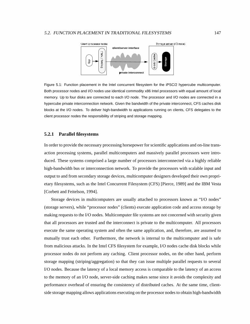
5.2. FUNCTION PLACEMENT IN TRADITIONAL FILESYSTEMS 147
�'� ��� �O�O�B�G��� �����G��� � ���O�O�O�O���� � �O�O�O� ��� �O�j�O�G�j�����O�O�O�O�
� ��
c� lient/server interface
Sto
rag
e
p� rivate interconnect
¡ ¢£¤¥ ¦£§ ¨
© ª «¬ �¬ ®¯°�±²
Figure 5.1: Function placement in the Intel concurrent filesystem for the iPSC/2 hypercube multicomputer.
Both processor nodes and I/O nodes use identical commodity x86 Intel processors with equal amount of local
memory. Up to four disks are connected to each I/O node. The processor and I/O nodes are connected in a
hypercube private interconnection network. Given the bandwidth of the private interconnect, CFS caches disk
blocks at the I/O nodes. To deliver high-bandwidth to applications running on clients, CFS delegates to the
client processor nodes the responsibility of striping and storage mapping.
5.2.1 Parallel filesystems
In orderto providethenecessaryprocessing horsepower for scientific applicationsandon-linetrans-
action processing systems, parallel multicomputers and massively parallel processors were intro-
duced. Thesesystemscompriseda largenumber of processors interconnectedvia a highly reliable
high-bandwidth busor interconnection network. To provide theprocessors with scalable input and
output to and from secondary storagedevices,multicomputer designersdevelopedtheir own propri-
etary filesystems, such astheIntel Concurrent Filesystem(CFS) [Pierce,1989] andtheIBM Vesta
[Corbett andFeitelson, 1994].
Storagedevices in multicomputers are usually attached to processors known as “ I/O nodes”
(storageservers),while “processor nodes” (clients) execute application codeand accessstorageby
makingrequests to theI/O nodes. Multicomputer file systemsarenot concerned with security given
that all processorsare trusted and the interconnect is private to the multicomputer. All processors
execute thesameoperating system and often the sameapplication, and, therefore, areassumedto
mutually trust each other. Furthermore, the network is internal to the multicomputer andis safe
from maliciousattacks. In theIntel CFS filesystem for example, I/O nodescachedisk blockswhile
processor nodes do not perform any caching. Client processor nodes, on theother hand, perform
storage mapping (striping/aggregation) so that they can issuemultiple parallel requeststo several
I/O nodes.Because thelatency of a local memory accessis comparable to thelatency of anaccess
to the memory of an I/O node, server-sidecaching makessense sinceit avoidsthe complexity and
performanceoverhead of ensuring the consistency of distributed caches. At thesame time, client-
sidestoragemapping allowsapplicationsexecutingontheprocessornodestoobtain high-bandwidth
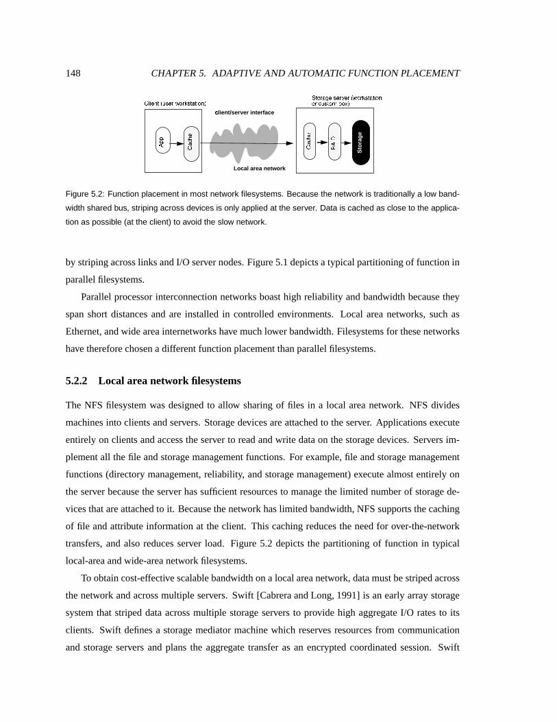
148 CHAPTER 5. ADAPTIVE AND AUTOMATIC FUNCTION PLACEMENT
�'� ��� �O�O�E�j��� ������� ³���� ´j�G� �O� � �O��µ� � �O�O�O� ¶O�G���G³���� ´G�j� �O� � �O�O�
� ��
Local area network
c� lient/server interface
Sto
rag
e
¥ ¦£§ ¨
°�±²
�����j¶O�G� �O·¹¸O�»ºj�
¥ ¦£§ ¨
Figure 5.2: Function placement in most network filesystems. Because the network is traditionally a low band-
width shared bus, striping across devices is only applied at the server. Data is cached as close to the applica-
tion as possible (at the client) to avoid the slow network.
by striping across linksandI/O servernodes.Figure5.1depictsa typical partitioning of function in
parallel filesystems.
Parallel processor interconnection networks boast high reliabili ty and bandwidth becausethey
span short distances andare installed in controlled environments. Local area networks, such as
Ethernet, andwidearea internetworkshavemuch lower bandwidth. Filesystemsfor thesenetworks
have thereforechosenadifferent function placement thanparallel filesystems.
5.2.2 Local areanetwork filesystems
The NFS filesystem was designed to allow sharing of files in a local area network. NFS divides
machinesinto clientsand servers. Storagedevicesareattachedto the server. Applications execute
entirely on clients and accesstheserver to readandwrite dataon the storagedevices. Servers im-
plement all the file and storagemanagementfunctions. For example, file and storage management
functions (directory management, reliabili ty, and storagemanagement) execute almost entirely on
the server becausethe serverhas sufficient resources to managethe limited number of storagede-
vicesthat areattached to it. Becausethe network has limited bandwidth, NFSsupports thecaching
of file and attribute information at theclient. This caching reduces the need for over-the-network
transfers, and also reducesserver load. Figure 5.2 depicts the partitioning of function in typical
local-areaand wide-areanetwork filesystems.
To obtain cost-effectivescalablebandwidth on a local areanetwork, datamust bestriped across
the network and across multiple servers. Swift [Cabreraand Long, 1991] is anearly array storage
system that striped data acrossmultiple storage serversto provide high aggregate I/O ratesto its
clients. Swift definesa storage mediator machine which reservesresourcesfrom communication
and storage servers andplans the aggregate transfer as an encrypted coordinated session. Swift

5.2. FUNCTION PLACEMENT IN TRADITIONAL FILESYSTEMS 149
mediators also manage cache coherence using call-backs, and bandwidth reservation by selecting
theappropriatestripeunit size. Swift delegates thestoragemanagementfunction to theservers (the
storagemediators). Applicationsexecuteentirely on clients.
5.2.3 Wideareanetwork filesystems
The Andrew filesystem (AFS) wasdesigned to enable sharing of data among geographically dis-
tributed client systems[Howardet al., 1988]. AFS has traditionally served an amalgamation of
widely distributed office and engineering environments, where sharing is rarebut important and
each client is anindependent system. Accordingly, the entire application executesat a client and a
larger fraction of theclient’s local disk is reserved for long-term caching of distributedfilesystem
data.
AFSisdesignedfor wideareaswherea local diskaccessis assumed muchfaster thanan access
to theserver. Consequently, local disk caching under AFS can improve performancedramatically.
Long-term local disk caching is very useful in environments with mostly read-only sharing such
asinfrequently updatedbinariesof sharedexecutables. Such caching reduces server loadenabling
relatively resource-poor AFSservers to support a largenumberof distant clients.
5.2.4 Storagearea network filesystems
Traditionally, the limited connectivity of peripheral storage networks (e.g. SCSI) constrained the
number of devices that can be attached to the server. Emerging switched networks are expand-
ing the connectivity and bandwidth of peripheral storage networks and enabling the attachment
of thousands of storage devices to the server. As a result, a single file server machine – usu-
ally a commodity workstation or PC – cannot handle file and storage management for this large
numberof devices. Consequently, recent research on network-attached storage has proposed of-
floading this function to “clients”, eliminating the legacy server, enabling striping acrossmul-
tiple servers, effectively replacing the server with a cluster of cooperating clients. Several re-
searchers have proposed scalable storage systems that comprise clusters of commodity storage
servers[Anderson etal., 1996, Thekkath et al., 1997, Gibson etal., 1998, Hartman etal., 1999] and
clients,which largely offload filesystemfunctionality fromserversto clientsto enable thescalability
of thedistributed filesystem.
Frangipani [Thekkathet al., 1997] is aclusterfilesystemwhich is built on topof closely cooper-
ating network-attached storageservers. Thestorageserversexport theabstraction of asetof virtual

150 CHAPTER 5. ADAPTIVE AND AUTOMATIC FUNCTION PLACEMENT
�'� ��� �O�O�B�G��� �����G� � �(� �O� � � �O�O�O��µ� � �O�O�O� ¼O�O�j�O³W��� ´j�G� �O� � �O�O�
Local or storage
c� lient/server interface
Sto
rag
e
¥ ¦£§ ¨
°�±²
�O� �j´G�
� �� ½�¦«ª¾
� �� ½�¦«ª¿
aÀ rea network
Figure 5.3: Function placement in active disk systems. The server in this case is a smart disk drive capable
of executing general purpose application code. The client is a host machine. The data intensive function of
the application (part2) is explicitly moved to the disk. A vestigial merge function (part1) is left at the host to
coordinate multiple remotely executing functions which can be potentially executing on several active disks.
disks. Eachvirtual disk is block-addressable, and blocks are replicatedacross servers for reliabil-
ity. Frangipani distributes its filesystem function (allocation, namespace management) to a set of
cooperating clients, called“file managers.” The file managers cooperatively implementa UFS-like
filesystemand synchronizeviaasharedlock manager. Measurementsof Frangipani report enhanced
scalability fromdistributed execution.
5.2.5 Activedisk systems
A growing numberof important applicationsoperateon largedatasets,searching, computing sum-
maries,or looking for specific patterns or rules, essentially “fi ltering” the data. Filter-li ke applica-
tionsoften makeoneor moresequential scansof thedata[Riedel et al., 1998]. Applicationsexecute
on the host, with the storage devices serving as block servers. Proponents of active disk systems
claim that the increasing levels of integration of on-disk controllers arecreating “excess” comput-
ing cycleson theon-disk processor. These cycles canbeharnessedby downloading “application-
specific” dataintensive filters. Currently, data-intensive applications execute entirely on the host,
oftenbottlenecking on transferring data from thestoragedevices(servers) to thehost (client in this
case). Figure5.3depictsthepartitioningof function in anactive disk system.
Table 5.1 summarizesthe function placement choices for a representative distributed storage
system in each of the above categories. For each system, the table shows wherecaching aswell
asother filesystemfunctions such as aggregation/striping and namespace management are placed.
Thetableshowsalsowhereapplication function is executed. Thetablesummarizesthis information
highlighting thefact that for each function, there is at least onesystemwhich choosesto place it at
theclient andat leastonesystemwhich choosesto placeat theserver.
5.2. FUNCTION PLACEMENT IN TRADITIONAL FILESYSTEMS 151
For each filesystem, the partitioning of function was heavily dictated by the topology of the
target environment and thecharacteristics of the important workloads. This makeseach filesystem
applicable only within the boundariesof the environments thatfit its original design assumptions.
Function partitioning in distributed filesystemshas been specialized in these systemsto the un-
derlying technologiesand target workloads. This specialization of course came at the expenseof
considerable developmenttime. Rewriting filesystemsto optimizefor details in theunderlying hard-
wareisnot cost-effectivein termsof development time. Moreover, rewriting filesystemsto optimize
for more detailed characterizations of theunderlying hardware stil l cannot adapt to changesin the
lif etimeof asingle workload,or to inter-application competition oversharedresources.
5.2.6 A motivating example
Considerthefollowing example demonstrating how adapting functionplacement betweenclient and
server canimprove filesystemperformance. Theprevious chapter presented a sharedstorage array
architecturecomposedof storagedevicesand storagecontrollers. In this chapter’s terminology, the
storagedevicesarethestorageservers and thestoragecontrollers are the clients. Let’s assume that
the storage device processors are limited compared to thatof thestorage controllers. Let’s further
assumethat thestoragenetwork connecting thedevicesto thecontrollersis relatively fast such that
the timestaken by a local anda remoteaccessbetween thenodesare relatively indistinguishable.
In thiscase,when thearray is in degradedmode,it is advantageous to execute thereconstruct-Read
BSTs(XOR intensiveoperationsneeded to computethecontentson thefailed device) onthestorage
controller. Thestorage controller hasa fastCPUand transferring the data on thenetwork does not
add observable latency.
Now consider thecasewherethestoragedevicesareupgradedsuch thatexecuting XORson the
devicesis 5X faster. Then, executing thereconstruct-ReadBST on thedevice side will be5 times
faster. If we alsoassumethat thenetwork is of observable latency becauseof highly active storage
controllers, theperformanceimprovement of device-sideexecutioncanbeevenhigher.
Traditionally, theserver interfacedefineswhat function executesat theserver, everything else
executesattheclient. Thisinterfaceis decided atsystem designtimeby serverimplementors. Client
programmershaveto abideby thisdivisionof labor. Server interfacedesignersfactor in assumptions
about the relative availability of resourcesat the client and theserver, their relative levels of trust,
the performanceof theclient-server network and thekey characteristics of the expectedworkload.
Theseassumptionsdonot matchtherealitiesof several systemsandworkloads.Theresult is subop-
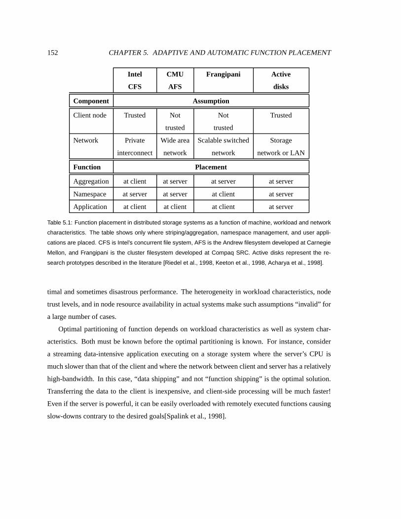
152 CHAPTER 5. ADAPTIVE AND AUTOMATIC FUNCTION PLACEMENT
Intel CMU Frangipani Active
CFS AFS disks
Component Assumption
Client node Trusted Not Not Trusted
trusted trusted
Network Private Widearea Scalableswitched Storage
interconnect network network network or LAN
Function Placement
Aggregation atclient at server at server at server
Namespace at server at server at client at server
Application atclient at client at client at server
Table 5.1: Function placement in distributed storage systems as a function of machine, workload and network
characteristics. The table shows only where striping/aggregation, namespace management, and user appli-
cations are placed. CFS is Intel’s concurrent file system, AFS is the Andrew filesystem developed at Carnegie
Mellon, and Frangipani is the cluster filesystem developed at Compaq SRC. Active disks represent the re-
search prototypes described in the literature [Riedel et al., 1998, Keeton et al., 1998, Acharya et al., 1998].
timal andsometimesdisastrousperformance. The heterogeneity in workload characteristics, node
trustlevels, andin noderesourceavailabilit y in actual systemsmakesuchassumptions“invalid” for
a largenumberof cases.
Optimal partitioning of function depends on workload characteristics as well as system char-
acteristics. Both mustbe known before theoptimal partitioning is known. For instance, consider
a streaming data-intensive application executing on a storage system where the server’s CPU is
much slower thanthatof theclientand where thenetwork betweenclient andserverhasarelatively
high-bandwidth. In this case, “datashipping” and not “function shipping” is the optimal solution.
Transferring the data to the client is inexpensive, and client-side processing will be much faster!
Evenif theserver is powerful, it can beeasily overloaded with remotely executedfunctionscausing
slow-downscontrary to thedesired goals[Spalink et al., 1998].

5.3. OVERVIEW OF THE ABACUS SYSTEM 153
5.3 Overview of the ABACUS system
To demonstratethebenefits andthefeasibility of adaptive function placement, this chapter reports
on the design and implementation of a dynamic function placement system and on a distributed
filesystembuilt on it. Theprototypeis calledABACUS becausefunctionsassociatedwith aparticular
datastream (file) canmove back and forth between theclientand theserver.
5.3.1 Prototypedesign goals
ABACUS is designedprimarily to support filesystems and stream-processing applications. Filesys-
tems and stream-processing applications move, cache and process large amounts of data. They
perform several functions on the data-stream asit movesfrom the base storageserver to the end
consumerat the client node. Intuitively, the purposeof ABACUS is to discover enough about the
resource consumption patterns of the functional components in the stream and about their mutual
communication to partition them optimally between the client and the server. Components that
communicateheavily should beco-locatedon the samenode. At thesametime, the CPU at a node
should not be overloaded and loadshould bebalancedacross them. Sensitive functions should be
executed on nodes marked trusted. ABACUS therefore seeks to automateperformance and con-
figuration management and simplify filesystem development by removing from the filesystem and
application programmer the burdenof load balancing and configuration. Particularly, theABACUS
prototypeis designed to meet two principal requirements: to offer anintuitive programming model
and to intelli gently partition function without user involvement.
Intuitive programming model. The ABACUS-specific efforts expended by the programmer to
write a filesystem or application on ABACUS should be limited relative to designing a filesystem
or application for a traditional fixedallocation of function. In principle, automating function place-
mentfrees theprogrammerfrom theburdenof optimizing the application for each combination of
hardwareand environment. ABACUS should makeit easyfor programmersto write applicationsso
that the effort saved by not developing system-specific optimizations is not replaced by theeffort
takento codein ABACUS.
Flexible and intelligent partitioning. The system should partition function sothat optimal per-
formance is achieved. In this research, performance is taken to be equivalent to “total execution
time.” The system, therefore, should partition function so that, in aggregate, applications should
take theminimal amount of execution time.

154 CHAPTER 5. ADAPTIVE AND AUTOMATIC FUNCTION PLACEMENT
5.3.2 Overview of theprogramming model
ABACUS consists of a programming model anda run-time system. The ABACUS programming
model encouragestheprogrammerto composeapplicationsfrom small components each perform-
ingafunctional steponadatastream.Therun-timesystemcontinuouslyobserveseachcomponent’s
behavior and systemresource availabilit y, using theseto assign thecomponent to thebest network
node.
Object-orientedlanguagessuchasC++and javaarewidelyused in buildingdistributedanddata-
intensive applications. ABACUS choosesto monitor application objects (run-time instantiations of
classes)andwork to “place” themin themostpropernode.
Component objects in an ABACUS application can be declared aseither mobile or anchored.
Mobile objectscanbeadaptively bound to client or to server at application start-time. They canalso
change placement at run-time. Mobile objects provide methods that explicitly checkpoint to and
restoretheir statefromabuffer. Thecheckpoint/restoremethodsareimplementedassuming
the object is quiescent, that is, not actively executing any externally exported method. Anchored
objects, on theother hand, arefixedto a location determinedby the designer at application design
timeandnevermigrate.
When thesystemis running, theapplication is represented asagraph of communicating mobile
objects. Each objectembodiesstateandprovidesaninterfaceto theexternal methodswhich canbe
invokedto operateon that state. Theobject graph canbethought of as rootedat thestorageservers
by anchored(non-migratable) storageobjects and at theclient by ananchoredconsole object. The
storage objects provide persistent storage, while the console object contains the part of the appli-
cation which must remainat thenode wheretheapplication is started. Usually, theconsole part is
not data intensive. Instead, it servesto interfacewith the user or therestof the system at thestart
node. Objectsmakemethod invocationsto each other, resulting in datamoving between them.The
data-intensiveassumption implies that theapplicationmovesa largeamount of dataamongasubset
of thecomponent objects.
Component object-based applications
The ABACUS prototype was developed to manage thepartitioning of applications written in C++.
While javawould have been amoreappropriate languagebecauseof its platform-independence, its
limited performance on Linux during the time this research was conducted made it a badchoice.
However, the reader will find out that the architecture of ABACUS and its resource management

5.3. OVERVIEW OF THE ABACUS SYSTEM 155
CÁ
onsole
CÁ
ache
RÂ
AID
AÃ
nchor eÄ d object (NASD object, Console)
PÅ
r ivate state: local (embedded object)
Pr ivate state: r eÄ fer eÄ nce to external object
NÆ
ASD NÆ
ASD
UÇ
ser application
oÈ pen(), close(), r eÄ ad(), wr ite()
CÁ
ompression
Mobile object
VÉ
FS inter face, open file descr iptors
Figure 5.4: A filesystem composed of mobile and anchored objects. The open file table and VFS layer interface
code is encapsulated in the console object which does not migrate. Storage is provided by disk-resident
functions encapsulated in a base storage service exporting a NASD interface. The intermediate objects shown
in the figure perform compression, RAID and caching functions and are mobile. These can migrate back and
forth between client and server.
algorithms canbeequally applied to a java-basedapplication.
There are two kindsof “applications” thatcanrun on ABACUS, filesystems anduser-level ap-
plications. In the caseof a filesystem, the console object corresponds to the codein theoperating
system which manages open file tables and implements VFS-layer functions. This layer doesnot
move from the client host. Filesystem objects (e.g. caching, RAID, compression and directory
management) do migrate back and forth between the client and the server. Storage accessis im-
plemented by a disk-resident function encapsulated in a C++ “NASDObject” class. This classis
instantiated on each storage server. The instantiated C++ object is anchoredto theserver and does
not migrate. Figure5.4shows a filesystembuilt on ABACUS. This discussion will sometimesrefer
to such afilesystem asamobile filesystem.
In thecase of a user-level program, theconsole consistsof themain function in a C/C++ pro-
gram. This console part initiatesinvocationswhich are propagatedby theABACUS run-time to the
rest of the objects in the graph. Theapplication can becomposedof multiple mobile objects per-
forming data-intensiveprocessing functionssuchasdecoding, filtering, counting and datamining.
Fromhereon, the discussion will focuson filesystems. Supporting themigration of user-level
application objects when such applications are layered atop the filesystem requires making the

156 CHAPTER 5. ADAPTIVE AND AUTOMATIC FUNCTION PLACEMENT
Fi leSys
CÁ
ache
Anchor eÄ d object (NASD object, Console)
PÅ
r ivate state: local (embedded object)
Pr ivate state: r eÄ fer eÄ nce to external object NÆ
ASD
UÇ
ser application
oÈ pen(), close(), r eÄ ad(), wr ite()
MÊ
obile object
CÁ
onsole
CÁ
ount
FË
ilter
main() and r eÄ st of non-migratable code in app
cÌ ount matching r eÄ cords
sÍ ear cÌ h for r eÄ cords that match cr iter ia
Figure 5.5: A user level application and its filesystem. Both are written such that their functions can migrate.
The console is the main function in the application that displays the results on the screen and interacts with
the local client. The file system is composed of layers that are encapsulated into migratable objects. The state
relevant to the process’ open files in the kernel is encapsulated into a migratable object (FileSys) that can
migrate to the server.
filesystem console layer (encapsulated asa FileSysobject in Figure 5.5) itself migratable. This
poseswell-known complicationsbecausesomestate, such asopen-file descriptors,cannot beeasily
transferredtransparently between nodes[Douglis, 1990]. Figure 5.5depicts anapplication written
on ABACUS. A discussionof how ABACUS canbeextended to support themigration of application
objectsisdeferredto Section 5.7.
As far astheABACUS run-time is concerned, both filesystems and user applicationsappear as
a graph of self-containedobjects thatcanbe monitoredas black-boxesandmoved back and forth
betweenthe client and the server asappropriate. The only property that the run-time caresabout is
whether theobjectcanbemovedor not (mobile or anchored).
ABACUS applicationsperform dataprocessingby invoking methodsthatstart at theconsole and
propagate through the object graph. In general, an application such asa filesystem decomposes
its processing into a set of objects, with each object providing a specific function. Theseobjects
can evenbeadaptively boundon aperfile basisto providedifferent services.For instance,caching,
reliability andencryption arefunctionsthatmay haveto beperformedon thesamefile. ABACUS en-
ablesfilesystemsandstorage-intensiveapplicationsto becomposed of explicitly migratableobjects,
providing storageservicessuchasaggregation,reliabili ty (RAID), cacheabili ty, filters,aggregators,
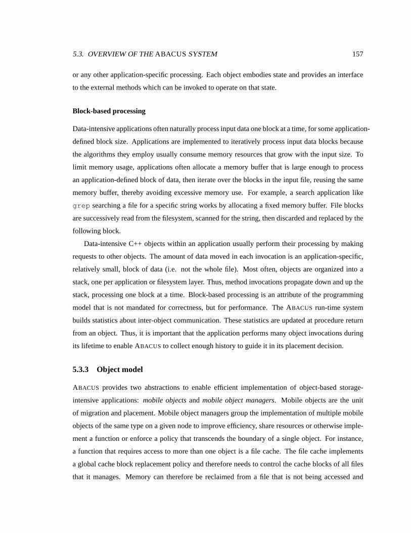
5.3. OVERVIEW OF THE ABACUS SYSTEM 157
or any other application-specific processing. Eachobject embodies stateandprovidesan interface
to theexternalmethodswhichcan beinvoked to operateon thatstate.
Block-basedprocessing
Data-intensiveapplicationsoftennaturally processinputdataoneblock at atime, for someapplication-
definedblock size. Applicationsare implemented to iteratively process input datablocks because
the algorithms they employusually consume memoryresources that grow with the input size. To
limit memory usage, applicationsoften allocate a memorybuffer that is large enough to process
anapplication-definedblock of data, then iterate over theblocks in theinput file, reusing thesame
memorybuffer, thereby avoiding excessive memory use. For example, a search application like
grep searching a file for a specific string works by allocating a fixedmemory buffer. File blocks
aresuccessively readfromthefilesystem,scanned for thestring, then discardedand replacedby the
following block.
Data-intensive C++ objects within an application usually perform their processing by making
requeststo other objects. The amount of datamoved in each invocation is anapplication-specific,
relatively small, block of data (i.e. not the whole file). Most often, objects areorganized into a
stack, oneperapplication or filesystemlayer. Thus, method invocationspropagatedown andup the
stack, processing one block at a time. Block-based processing is anattribute of the programming
model that is not mandated for correctness, but for performance. The ABACUS run-time system
buildsstatistics about inter-object communication. These statisticsareupdatedat procedurereturn
from an object. Thus, it is important that theapplication performsmany object invocations during
its lifetime to enable ABACUS to collectenough history to guideit in itsplacement decision.
5.3.3 Object model
ABACUS provides two abstractions to enable efficient implementation of object-based storage-
intensive applications: mobile objects andmobile object managers. Mobile objects are the unit
of migration and placement. Mobileobjectmanagers group the implementation of multiplemobile
objectsof thesametypeonagivennodeto improveefficiency, share resourcesor otherwise imple-
menta function or enforce a policy that transcends theboundary of a single object. For instance,
a function that requires accessto more thanone object is a file cache. The file cache implements
a global cache block replacementpolicy and thereforeneeds to control the cacheblocks of all files
that it manages. Memory can therefore be reclaimed from a file that is not being accessed and

158 CHAPTER 5. ADAPTIVE AND AUTOMATIC FUNCTION PLACEMENT
allocated to another activeone.
Anchored objects
Because anchored objects arenot mobile, that is, will at all timesremainat the node where they
are instantiated, ABACUS placeslit tle restriction on their implementation. Examples of anchored
objects include NASD objects, which provide basic storage services, and atomicity objects which
provide atomicity for multi -block writes. Both NASD and atomicity objects are anchored to a
storageserver. On theotherhand, theconsole objectisanchored to theclient node.
Storageserversare assumed to implement a “NASD interface”. Storageon a storageserver is
accessed through a C++ object, referred to asa NASD anchored object, instantiated at run-time,
and implementing the “NASD interface” described in Chapter 3. ABACUS doesnot require that
storage accessfollows a NASD interface. The anchored C++ object providing storageaccess can
just as easily export a block-level interface. While C++ objects communicating with storage are
requiredto know theparticular interfaceexportedby storage,ABACUS doesnot. ABACUS treatsall
invocationsbetweenobjectsasmessages that transmit a certain amount of bytes,without attention
to semantics.
Mobile objects
A mobile object in ABACUS is explici tly declared by the programmer as such. It consists of a
stateandthe methods that manipulate that state. A mobile object is required to implement a few
methods to enable therun-time systemto create instantiationsof it and migrateit. Mobile objects
are usually of large granularity. Rarely are mobile objectssimple primitive typessuchas integer or
float. They usually performfunctionsof thesizeandcomplexity of afilesystemlayer, or adatabase
relational operator, such asfiltering, searching, caching, compression, parity computation, striping,
or transcodingbetween two dataformats.
Mobile objects, like all C++ objects,have privatestate that is not accessible to outside objects,
except through theexportedmethods. Unlike C++ objects, mobile objects in ABACUS do not have
public datafields thatcanbeaccesseddirectly by de-referencing a pointer to the objects. Instead,
all accessesto theobjectsstatemust occur throughexportedmethods.This restriction simplifies the
ABACUS run-timesystem. Sinceall accessesto amobileobjectoccur through its exportedmethods,
the run-time’ssupport for location transparency can be focussedon forwarding method invocations
to an object to thecurrentlocation of theobject.

5.3. OVERVIEW OF THE ABACUS SYSTEM 159
The implementation of a mobile object is internal to that object and is opaque to other mobile
objectsandto theABACUS run-timesystem. Theprivatestateconsistsof embeddedprimitive types
and instantiations of embedded classes (i.e. not visible outside the scope of the current object’s
class) and referencesto external objects. TheABACUS programming model makesarestriction that
all external references must beto other mobile or anchoredobjects that are known to the ABACUS
run-timesystem.Referencesto other external resourcessuchassocketsand shared memory regions
arenot legal.
ABACUS maintainsinformation about thelocationsof mobileandanchoredobjectsthat it knows
about. It uses this information to forward method invocations to objects asthey migrate between
client andserver.
Of course, a mobile objectcanhave accessto its local private state through references that are
not redirected or known to the ABACUS run-time system. The mobile object is responsible for
saving thisprivatestate, however, whenit is requestedto do so by thesystem,through theCheck-
point() method. It is also responsible for reinstating this state (reinitializing itself) when the
run-time system invokes the Restore() method. TheCheckpoint() method savesthestate
to either an in-memory buffer or to a NASD object. TheRestore() method can reinstate the
statefromeitherplace. Thesignaturesfor theCheckpoint() and Restore() methods,which
define the base class from which all mobile objects are derived, are illustrated in Figure5.7. The
discussion will differentiate private embedded state from mobile andanchoredobjects by referring
to mobile and anchored objects as “ ABACUS objects”, since they are the only objects known the
ABACUS run-timesystem.
Mobile objectmanagers
Mobile object managersencapsulateprivatestate for acollection of mobileobjectsof agiventype.
Often, a service is better implemented using a single object manager that controls the resources
for a group of objects of the sametype. Object managers thus aggregate the implementation of
multiple objects of thesame type. For example, a file systemmay wish to control thetotal amount
of physical memory devotedto caching, or the total number of threadsavailable to cacherequests.
Mobile objectmanagersprovidean interfacethatis identical to thatof thetypesthey contain except
thatthey takean additional first argument to eachmethodinvocation,whichrepresentsareferenceto
the individual object to be invokedfrom thecollection of objectsin theaggregatedmanagerobject.

160 CHAPTER 5. ADAPTIVE AND AUTOMATIC FUNCTION PLACEMENT
CÎ
onsole: 0
RÏ
AID: 2
SÐ
torage: 3
FÑ
ilter: 1
RAID: 2
ÒMÓ ÔOÕ+ÖO×OØ�ÒMØGÕ+Ù�ØGÕ
ÚMÛ Ü ØGÝMÓ
ÞÞ ß
Loc
atio
n tr
ansp
aren
t in
voca
tion
Loc
atio
n tr
ansp
aren
t in
voca
tion
Res
ourc
e m
onito
ring
&
man
agem
ent
Res
ourc
e m
onito
ring
&
man
agem
ent
Aà
bacus run-time
Uá
M
Uá
Mâ
M Uá
(digests oã f stats)
Figure 5.6: An illustration of an ABACUS object graph, the principal ABACUS subsystems, and their interactions.
This example shows a filter application accessing a striped file. Functionality is partitioned into objects. Inter-
object method invocations are transparently redirected by the location transparent invocation subsystem of the
ABACUS run-time. This subsystem also updates the resource monitoring subsystem on each procedure call
and return from a mobile object (arrows labeled “U”). Clients periodically send digests of the statistics to the
server. Finally, resource managers at the server collect the relevant statistics and initiate migration decisions
(arrows labeled “M”).
5.3.4 Run-time system
Figure 5.6 represents an overview of the ABACUS run-time system, which consists of (i) a migra-
tionand location-transparent invocationsubsystem,or binding manager for short; and (ii ) aresource
monitoring and management subsystem,resource manger for short. The first subsystem is respon-
sible for the creation of location-transparent references to mobile objects, for the redirection of
method invocations in thefaceof object migrations,and for enactingobjectmigrations. Finally, the
first subsystemnotifies thesecondat each procedurecall and return from amobileobject.
The resource manager usesthe notifications to collect statistics about bytes moved between
objectsandabout theresources usedby active objects (e.g.,amount of memoryallocated, number
instructions executed per byte processed). Moreover, this subsystem monitors the availability of
resourcesthroughout the cluster (node load, available bandwidth on network links). An analytic
model isusedto predict theperformancebenefit of moving to an alternative placement. Themodel
alsotakes into account thecost of migration— the timewastedto wait until theobject is quiescent,
checkpoint it, transfer its state to the target node and restore it on that node. Using this analytic
model, thesubsystem arrivesat theplacement with thebest netbenefit. If this placementis different

5.3. OVERVIEW OF THE ABACUS SYSTEM 161
from thecurrentconfiguration, thesubsystemeffectsobject migration(s).
The ABACUS run-time system hasmechanismsto find application objects and migrate them.
In general, when a function is moved, both the code for the function as well as its execution
state(local and external referencesaccessedby the function) must be made accessible at the new
node [Julet al., 1988]. A mechanism to transfer this state from one node to another is therefore
necessary to enableadaptive functionplacement at run-time.
Emerald [Jul etal., 1988] is a seminal implementation of a languageand run-time systemsup-
porting themobility of application objects. ABACUS usessimilar mechanisms to thoseprovidedby
Emerald to enact object mobility. The focus of the ABACUS prototype, however, wasnot on mo-
bility mechanismsbut rather on using thesemechanisms to improve data-intensive and filesystem
performancethrough judicious and automatic placement of their objects on the proper nodes. The
remainderof this sectiondescribesthemechanismsusedby theABACUS to effect objectmigrations
and to find objectsafter they migrate. Thefollowingsection is devotedto describing thealgorithms
usedby the run-time systemto achievegoodplacement for applicationobjects.
Creating and invoking mobileobjects
Thecreation of mobile objects isdonethrough theABACUS run-timesystem. When thecreation of
a new ABACUS object is requested, the run-time system allocatesa network-wide uniquerun-time
identifier (rid) for thenew object. This identifier is returnedto thecaller andcanbeusedto invoke
thenew mobile object from any node,regardlessof thecurrent location of themobile object. After
allocating a network wideuniquerid, therun-time systemcreates theactual object in memory by
invoking the object manager for that type. If no object manager exists, oneis createdfor that type.
Object managersmust implementaCreateObj() method which takesargumentsspecifying any
initialization information and returns a reference that identifies the new object within that object
manager. This can be thought of as a virtual memory referenceto thecreatedobject, although the
object manager is freeto construct this referencein the way it desires. The object manager creates
the “actual” object, e.g., in C++, by invoking thenew operator, and then return a reference to the
object to therun-time. This reference,called a“manager reference”, is used to uniquely identify the
object within thecollection of objectsmanagedby themanager.
The run-time system maintains tables mapping each rid to a (node, object manager, man-
ager reference) triplet. As mobile objects move betweennodes, this table is updatedto reflect the
new node, new object manager, and new manager reference. Mobile objects usetherid to invoke
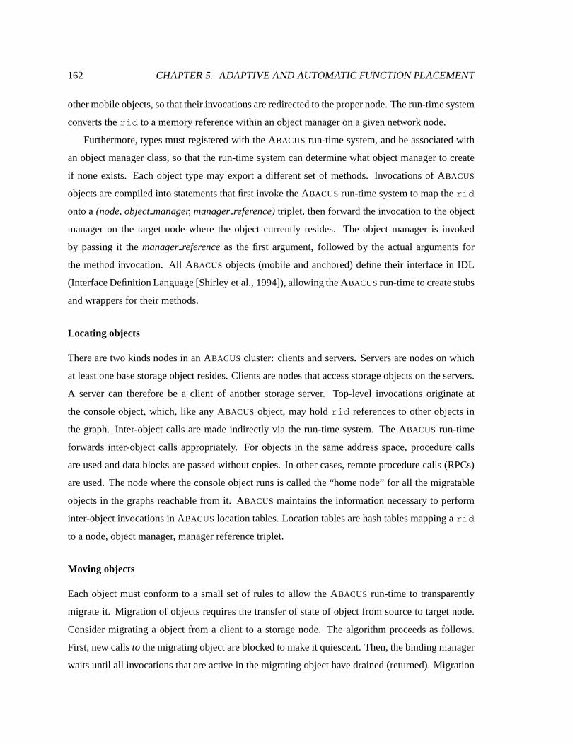
162 CHAPTER 5. ADAPTIVE AND AUTOMATIC FUNCTION PLACEMENT
other mobile objects, sothattheir invocationsareredirected to thepropernode. Therun-timesystem
converts therid to amemory referencewithin anobject manageron agivennetwork node.
Furthermore, typesmust registeredwith theABACUS run-time system, and beassociatedwith
anobjectmanager class,so that the run-time systemcandeterminewhat objectmanager to create
if none exists. Each object type may export a different set of methods. Invocations of ABACUS
objectsarecompiled into statementsthat first invoke theABACUS run-timesystem to maptherid
onto a (node,object manager, manager reference) triplet, thenforwardtheinvocation to the object
manager on the target node where the object currently resides. The object manager is invoked
by passing it the manager referenceas the first argument, followed by the actual arguments for
the method invocation. All ABACUS objects (mobile andanchored) definetheir interface in IDL
(InterfaceDefinitionLanguage[Shirley etal., 1994]), allowingtheABACUS run-timeto createstubs
and wrappers for their methods.
Locating objects
There are two kinds nodesin an ABACUS cluster: clients and servers. Servers arenodes on which
at least onebasestorageobject resides. Clientsarenodes thataccessstorageobjectson theservers.
A server can therefore be a client of another storage server. Top-level invocations originate at
the console object, which, like any ABACUS object, may hold rid referencesto other objects in
the graph. Inter-object calls are made indirectly via the run-time system. The ABACUS run-time
forwards inter-object calls appropriately. For objects in the sameaddressspace, procedure calls
are used and data blocks arepassed without copies. In other cases, remote procedure calls (RPCs)
are used. The nodewhere the console objectruns is called the “homenode” for all themigratable
objects in thegraphs reachable from it. ABACUS maintains the information necessary to perform
inter-object invocationsin ABACUS location tables.Location tablesarehash tablesmapping arid
to a node,object manager, manager referencetriplet.
Moving objects
Eachobject must conform to a small set of rules to allow the ABACUS run-time to transparently
migrateit. Migration of objects requires the transfer of stateof object from source to target node.
Consider migrating a object from a client to a storage node. The algorithm proceeds asfollows.
First, new calls to themigrating object areblockedto make it quiescent. Then,thebinding manager
waitsuntil all invocations thatareactive in themigrating object have drained(returned). Migration

5.4. AUTOMATIC PLACEMENT 163
is canceled if this step takes too long. Oncethe object is quiescent, it is checkpointed, its state
transferred andthe checkpoint restored to a newly created object of the same type on the storage
node. Then, local and remotelocation tablesareupdated to reflect thenew object placement. Next,
any waiting invocationsareunblocked and areredirectedto theproper nodeby virtueof theupdated
location table. This algorithmextends to migrating wholesubgraphsof objects.
ABACUS requires thateachmobile object in thegraph implementaCheckpoint() andRe-
store() method which conclude any background work and then marshall and unmarshall an
object’s representation into migratable forms. The mobili ty of code is ensured by having nodes
that do not have the code for an objectreadit from sharedstorage. Themobilit y of execution state
is enacted through application specific checkpointing. A Checkpoint() message is sent to the
object on migration. Theobject marshalls its private state to a buffer and returns it to the runtime
system which passes it to the Restore() method at the target node. This method is invoked to
reinitialize thestateof theobject beforeany invocationsareallowed.
5.4 Automatic placement
This section describes the performance model and the algorithms used by the ABACUS run-time
system to drive placement decisions. ABACUS resource managers gather per-object resourceusage
and per-node resourceavailabili ty statistics. The resourceusage statistics areorganizedas graphs
of timed data flow among objects. The resource manager on a given server seeksto perform the
migrationsthat will result in the minimal average application completion time across all theappli-
cationsthatareaccessing it. Thisamountsto figuringout whatsubsetof objectsexecuting currently
// the abstract mobile object class
// NäasdId: a unique identif
ier for a på ersisent base storage object cæ lass abacusMobileObject {
pç ublic:int Checkpoint(void **buffer, NasdID nasdId, int *csize);
int Restore(void *buffer, NasdId nasdId, int csize);
};
Figure 5.7: The interface of a base mobile object in the ABACUS prototype. The interface consists of two
methods: Checkpoint() and Restore(). The type NasdId denotes the set of all NASD identifiers. The
notation is in C++. Hence, the “*” symbol denotes an argument that is passed by reference. csize represents
the size of the checkpoint created or passed in the buffer.

164 CHAPTER 5. ADAPTIVE AND AUTOMATIC FUNCTION PLACEMENT
on clients canbenefit most from computing closer to the data. Migrating an object to the server
could potentially reducethe amount of stall time on thenetwork, but it could alsoextendthe time
theobject spendscomputing if theserver’sprocessor is overloaded.
Resourcemanagersat theserversuseananalytic model to determine which objectsshould be
migrated from the clients to the server and which objects, if any, should be migrated back from
the server to the clients. The analytic model considers alternative placement configurations and
selects the one with thebest net benefit, which is the differencebetween the benefit of moving to
thatplacementand thecostof migrating to it.
A migration is actually enacted only if theserver-side resourcemanager findsa new placement
whoseassociated net benefit exceedsa configurable threshold, èêéìë�íZî%ïðë . This threshold value is
usedto avoid migrationsthat chasesmall improvements, and it canbeset to reflectthe confidence
in theaccuracy of themeasurementsand of thepredictiveperformancemodel usedby the run-time
system.
While server-side resource managers can communicate with each other to coordinate the best
global placement decision, this would causeextra overheadandcomplexity in configuring thestor-
age servers. Under such ascheme,storageservers have to know about each other and beorganized
intocooperatinggroups.TheABACUS implementation foregoesthisextrabenefitof server-to-server
coordination for the sakeof robustnessandscalability. ABACUS server-side resourcemanagers do
not communicatewith one another to figure out the globally optimal placement. A server-sidere-
sourcemanager decideson thebest alternative placementconsidering only theapplication streams
thataccessit.
At any point in time, theobjectgraphfor an application is partitioned betweenclientandserver.
For a server-side resource manager to determine the best placement decision, it must know the
communication and resource consumption patterns of theobjects thatare executing on theclient.
Given information about the client-side aswell as local subgraphs, and given statisticsabout node
load and network performance, the resource manager should be able to arrive at the mostproper
placement.
This is implemented in ABACUS by having server-side resource managers receive per-object
measurements from clients. A server-side resourcemanageralso receives statisticsabout the client
processor speedand current load and collects similar measurements about the local system and
locally executing objects. Given the data flow graph between objects, the measured stall time of
client-side objects’ requests for data, andthe round-trip estimated latency of the client-server net-

5.4. AUTOMATIC PLACEMENT 165
work link, the model estimatesthe change in stall time if an object changes location. Given the
instructions per byte and therelative load and speed of theclient/server processors, it estimates the
changein execution time if theobjectismovedto anew node.
Thissimplemodel would suffice if theserver resourceswerenot shared by many clients. How-
ever, this isveryrarely thecase in practice.Underarealistic scenario, amigration of anobject from
a client to a server may slow-down other objects. This effect must be takeninto account by the
ABACUS performancemodel.
In addition to the change in execution time for the migrated object, the model also estimates
the change in execution time for the other objects executing at the target node (asa result of the
increased load on the node’s processor). Together, the changes in stall time and execution time
amount to the benefit of the new placement. In computing this benefit, the analytic model assumes
that history will repeatitself over thenext window of observation (thenext ñ seconds). Thecost
associatedwith a placement is estimatedasthesum of a fixedcost (the time taken to wait until the
object is quiescent) plusthetimeto transfer theobject’sstatebetweensourceand destinationnodes.
This latter value is estimatedfrom thesize of thecheckpoint buffer and thebandwidthbetweenthe
nodes.
5.4.1 Goals
There areseveral different performancegoals that the ABACUS run-time system canpursue. One
alternative is to allocate server resourcesfairly among competing client objects. Alternatively, the
system can provide applications with performance guaranteesandallocate resourcesto meet the
promised guarantees. Yetanothergoalwould be to minimizetheutilizationof thenetwork. Finally,
one goal is maximizea global metric associatedwith user-perceived performance,such asaverage
completion timeof applications.
This chapter describes algorithms that pursue a performancegoal which is widely sought in
practice, namelythatof minimizing theaverage completion time of complete runs of applications.
This goal is widely used because it directly maps onto a user-perceived notion of performance.
The performance model in ABACUS is self-contained,however, andcan be extendedor modified
to implement different policies. The run-time system makesdecisions to adapt the allocation of
server resources to minimize average requestcompletion time. We assume here that no explici t
information about the future behavior of applications is disclosedto the system. Instead, ABACUS
assumes that thefuturebehavior of applications is accurately predictedby their recent past.

166 CHAPTER 5. ADAPTIVE AND AUTOMATIC FUNCTION PLACEMENT
Note that the goal of minimizing the number of bytesmoved over the network is not always
desirable. For example, consideraclient-sidecachethat is aggressively prefetching file blocksfrom
a server to hide network latency from applications. While the cacheconsumesa lot of network
bandwidth and movesa large number of bytes, it doessave cache misses and reducesapplication
stall time. Moreover, this goal presumesthat moving bytes over the network has uniform cost.
In practice, not all communications are equally costly (at least in termsof latency) because the
available bandwidth of network links varies across topologies and with time as a function of the
applied load.
5.4.2 Overview of theperformancemodel
TheABACUS run-timemust identify theassignment of mobile objectsto network nodesthat is best
in reducing the average completion time. This discussion considers a single server casebut with
multiple clients accessing it. A cost-benefit performance model is derived for this case. Servers
in ABACUS act independently and do not coordinate resource allocation decisions. This design
requirement wasmade to limit complexity and improve robustness.
An ABACUS cluster is composed of clients and servers. The mobile objects associatedwith an
openfile start executing by default on their “homenode”, the node where thefile wasopen. They
can migrateto one of the storageservers, wheretheNASD objectsstoring that file reside. At any
point in time, the graph of mobile objects associated with a given file is partitioned between the
homenodeand thosestorageservers, referred to as the “basestorageservers.”
Theserver is shared by many clientsandhostsanumber of non-migratableobjectsthatprovide
basicstorageservicesto end clients. Becausenon-migratableobjectscannot beexecutedataclient,
while “mobile” objects can, the ABACUS run-time system is concerned with allocating serverre-
sourcesbeyond what is consumed by non-migratable objects to “mobile” application objects. The
ABACUS server-side resource manager is responsible for allocating its resourcesto theproper mo-
bile objects such that the performance goal is maximized. To estimate the average application
completion time given an object placement, an analytic model that estimatesaverage application
execution time in termsof inherent or easily measuredsystem and application parametersis devel-
oped. The discussion first considers the caseof a single application executing by itself. Then, it
generalizes themodel to handle thecaseof concurrent applications.
Figure5.8showsasketch of an applicationsexecuting onaclient and accessing astorageserver.
Filesystemand application objects areorganizedinto layers. Theapplication’s console makes iter-

5.4. AUTOMATIC PLACEMENT 167
ò\ó ôöõø÷IùWú
Network
ûIõ�ü%ý(õ�ü
P 0þ
C ÿ
P 2� P 3�
Storage Object (O n� +1 )
P 1
ò\ó ôöõø÷Iù��Console object (O 0þ ) Object O 1
Object O 2
Object O 3� P n� +1
Figure 5.8: This figure shows how mobile objects interact in a layered system. Most of the invocations start at
the topmost console object, trickling down the layers. An object servicing a request may invoke one or more
lower level mobile or NASD objects.
ative requests that trickle down the layers, causing anamount of data to be read from storageand
processed,andpassedup. At eachlayer someprocessing occurs, reducing or (seldom) expanding
the amount of datareturnedback up to the upper layer. Similarly, the application can be writing
data to stable storage, where dataflows downward through the layers, each layer performing some
processing andpassing the data down. This layered model of processing simplifies the analysis,
yet it is general enough to capture a largeclassof filesystemanddata-intensive applications. Mo-
bile objects perform two kindsof activities:computing (executing instruction on thelocal CPU) or
communicating(making amethod invocationsto another mobileor NASD object). Oneobject may
invokemore thanoneobjectin a lower layer.
To describe theanalytic model in detail, a few definitionsandnotationsare required. An object���is characterizedby an inherent processing ratio, expressed in instructions/byte, denotedby � � .
This ratio capturesthe inherent compute-intensivenessof theprocessing performed by theobject on
eachbyteof dataandis independent of theprocessor speed or thebandwidth available to theobject.
It canthereforebeused in estimating theexecution time (to processone block) of the object when
movedbetween nodes.
In this discussion, the raw processing rateof node ’s processor is denotedby �� , expressedin
instructionsper second. Theeffectiveprocessing rate of node asobservedby anexecuting object� �on that node is denoted by � . This is equal to the effective processing rateavailable from the
processor’s node,denotedas �� , and is less than the raw processing rate of theprocessorbecause
multiple threadsmay becontending on theprocessor. Of course, theobviousinequality holdsat all

168 CHAPTER 5. ADAPTIVE AND AUTOMATIC FUNCTION PLACEMENT
times,for all objects� �
executing on node :
��� �������5.4.3 Singlestack
Consider theapplication of Figure 5.8. Assume that each object is associated with a single thread.
The thread awaits invocations, performs some processing then invokes one mobile object at the
lower layer. Thethreadblocksuntil theinvocation returns.A singleNASD objecton asingleserver
is accessedby theapplication. Thebandwidth of read or writerequests to aNASDobject isdenoted
by � . This is assumed to be independent of server load, becausethe server is assumedto serve
NASD requestsatahigherpriority than remotely executingobjects.
Invocationsstart at theconsoleobject and trickle down objects���
through���
. Theapplication
is observed overawindow of time ñ during which � console requestsareinitiated and completed.
Let’sdenoteby � � thetotal numberof bytesprocessed by object� �
during theobservationwindow.
Let � � denotethetimespent processing by object���
. Assume, without lossof generality, thatunder
the original placement, objects� �
through� � execute on the clientand objects
� ��� � through� �
execute on the server. The console is referred to as���
and the NASD non-migratable object is
denotedby� � � � . Theelapsed time for theapplication in Figure5.8 canbewrittenas:
"!$#%# ��&�(' � � �*)
�&�+' �-, � .�/103254
where ,76 denotesthecommunication “blocking” or “stall” timebetween� 6 and
� 6 � � . Commu-
nication time is the time during which the call thread blocks waiting for data to be sentor received
to the invokedobject. This does not include processing time at the invoked object, but the time
truly spent blocking while the data is being transferred. That is, after theprocessing at the invoked
object hascompleted. Equation 5.1 canbe rewritten in termsof inherent application and system
parameters, as follows:
"!$#%# ��&�8' � �
� � � �
)�&�+' � , � .�/10:9;4
Equation 5.2. expresses the processing time � � in terms of the instructions per byte executed
by theobject, thenumber of bytesprocessedby the object during the observation window, and the
effective processing rate � . The numerator � � � � represents the numberof instructions executed
by the object during the observation window, and the denominator is the virtual processor rate
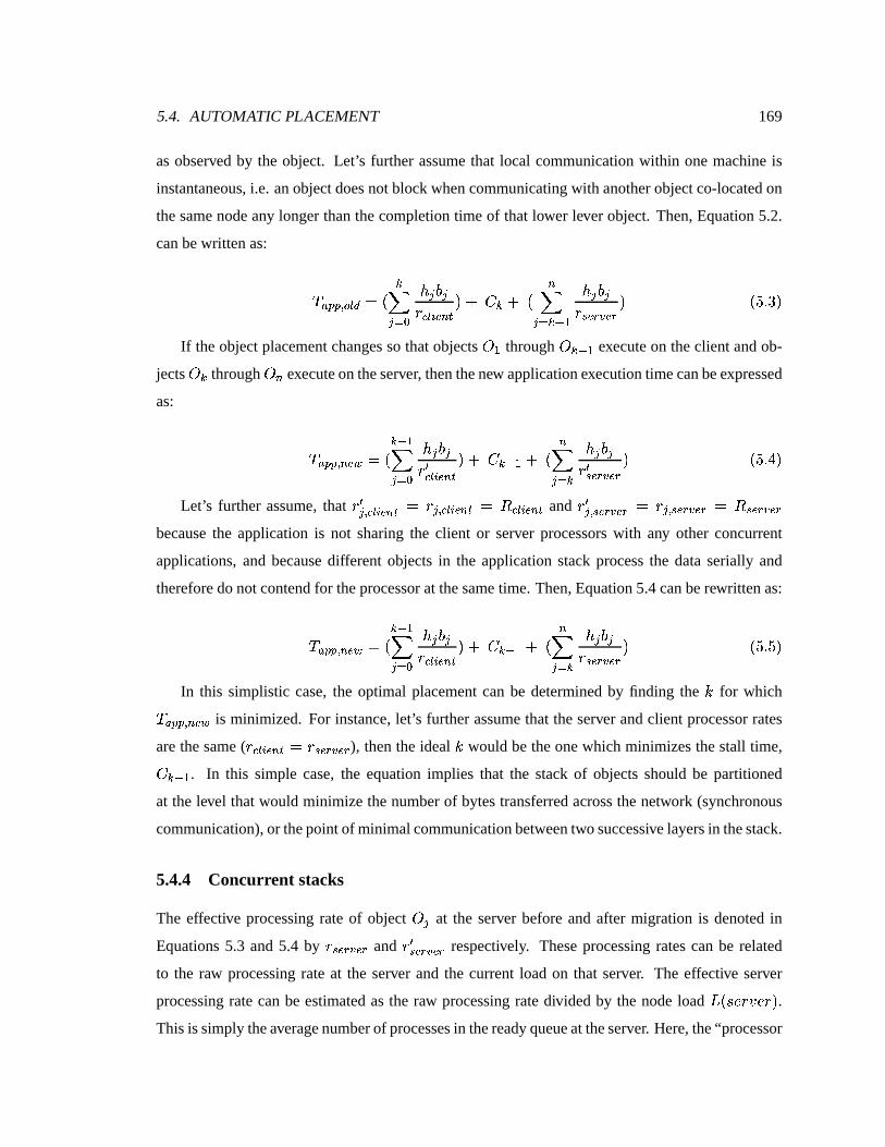
5.4. AUTOMATIC PLACEMENT 169
asobserved by the object. Let’s further assumethat local communication within one machine is
instantaneous, i.e. anobject doesnot blockwhencommunicatingwith another object co-located on
the samenode anylonger than thecompletion time of that lower lever object. Then, Equation 5.2.
can bewrittenas:
!<#=#5> ?A@:B � . �&�+' � � � � � �C @ 6 î ��D
4E) , � )F.�&
�8' ��� �� � � � ïMîðí$G�îMí
4 .�/10:HI4
If theobject placement changessothat objects� �
through� �KJ � execute on the client and ob-
jects� � through
� �executeon theserver, thenthenew application execution timecanbeexpressed
as:
!$#%#L> � î<M � . �KJ�&�8' � � � � � 5NC @ 6 î �5D
4E) , �KJ � )F.�&�+' �
� � � � NïðîðíAG�îðí
4 .�/10PO14
Let’s further assume, that N� > C @ 6 î �KD � � > C @ 6 î �5D � �C @ 6 î �KD and N� > ïðîMí<Gµîðí � � > ïðîMíAGWîMí � ïMîðíAGWîMíbecause the application is not sharing the client or server processors with any other concurrent
applications, and because different objects in the application stack process the data serially and
thereforedonot contend for theprocessor at thesame time. Then, Equation5.4 can berewritten as:
!$#%#L> � î<M � . �KJ�&�8' � � � � � C @ 6 î �5D
4E) , �KJ � )F.�&�+' �
� � � � ïðîðíAG�îðí
4 .�/10:/I4
In this simplistic case, the optimal placement can be determinedby finding the for which !<#=#L> � îQM is minimized. For instance, let’s further assumethat theserver and client processor rates
are thesame( �C @ 6 î �5D � �ïðîðíAG�îMí ), thenthe ideal would be theonewhich minimizes thestall time,
, �RJ � . In this simple case, the equation implies that the stack of objects should be partitioned
at the level thatwould minimize thenumberof bytestransferredacrossthe network (synchronous
communication), or thepoint of minimalcommunicationbetweentwo successivelayersin thestack.
5.4.4 Concurr ent stacks
The effective processing rate of object� �
at the server before and after migration is denoted in
Equations 5.3 and 5.4 by ïøîMíAG�îøí and NïðîðíAGµîøí respectively. Theseprocessing ratescan be related
to the raw processing rateat the server and the current load on that server. The effective server
processing ratecanbe estimated asthe raw processing rate divided by the node load S .UT5V LW V 4 .This is simply theaveragenumberof processesin theready queueat theserver. Here,the“processor

170 CHAPTER 5. ADAPTIVE AND AUTOMATIC FUNCTION PLACEMENT
sharing” assumption is made sothat object� �
receivesa processing ratefrom theprocessor that is
the ratio of theraw rate to thecurrent load, or moreprecisely:
�ïMîøíAG�îMí � ïMîMí<GµîðíS .UT5V LW V 4
.�/10:X;4In general, any priority or processorscheduling scheme canbe supportedas long asABACUS
has anadequatedescription of it. However, a processor sharing policy at equal priority was chosen
for the implementation. S .UTKV LW V 4 at theserver canbemeasured. Thechange in S .�TKV LW V 4 asa
result of a relocation must be estimated. Eachactive graph canbe thought of ascontributing a load
between Y and2. Intuitively, theloadis interpretedasfollows. If the object graph is computing all
the time,never blocking for I/O, thenits associated load is2. If theobject graphis computing only�� � th of the time, then the load it contributes to thesystemis�� � . Thenodeloadis is simply thesum
over all theactivesessionsat theserver of their contributedload, or equivalently:
S N .�TKV LW V 4 � &!�ZL[ C D 6 Gµî$\�îZïZï 6 ? � ï ,
S .U]^4 .�/10`_I4
The load contributedby a session, , S .U]^4 canbe computedfrom thestall and processing time
of theentirestack, or:
, S .a]^4 � b��+' �c� � � �
, � ) b��8' � � �
.�/10:d;4Equation5.8computestheloadof activesession
]astheratio of theprocessing timeattheserver
to thetotal (processing and stall time). Theportion of thestack at theserveris passivewheneverthe
client part of thestack is active,or whenever data is being communicatedover the network. These
times aresummedover all theobjects in thesession. The processing time for anobject is simply
the ratio of the bytes processedby the effective processing rate. Expanding the processing time in
termsof theseparameters, Equation 5.8becomes
, S .U]e4 � b��8' ��� �gf3h ë hí<iajak�l$jak
, � ) b ��(' � f3h ë híQmonPp jaq(r ) b��+' �c� �sfth ë hí iajUkUl<jUk
.�/10:u;4
After object� � migratesto theserver, thenew loadcan becomputed by rewritingEquation 5.9:
, S N .a]e4 � b��(' � foh ë hí$viUjwkUl$jUk
, ��J � ) b ��J ��8' � f h ë híQmonPp jaq(r ) b��+' � f h ë hí$iajUkUl<jak
.U/^032 Y 4

5.4. AUTOMATIC PLACEMENT 171
Equation 5.10requires thenew effectiveprocessing rateof theserver’sprocessor. Theeffective
processor rate is simply theraw ratedividedby thenew node load S N .�T�V V 4 .5.4.5 Cost-benefit model
If the server hasforeknowledge of all theapplication that will start, then it can determine the best
“schedule” for allocating its resources to minimize average completion time. In theabsence of this
knowledge, theserver has to operatebased only onstatisticsabout thepast behavior of applications
that have already started. The approach implemented in the ABACUS prototype is to allocate the
server’s resources greedily to the currently known applications, and then reconsider the decision
whenotherapplicationsstart. The implementation of thisapproachis described in this section.
Becauseof theabsenceof futureknowledge,thegreedy algorithm may migrateanapplication to
theserver, and thenshortly after that, a moredata-intensiveapplication maystart. Becausethecost
of relocating objects is not negligible, ABACUS has to consider whether reallocating the server’s
resources to themore “deserving” application isworth it.
A cost-benefit model canbe used to drive such decisions. Each object relocation inducesan
overheadand thereforeaddsto theapplication execution time. It, of course,could potentially result
in substantial savings in execution(stall) time. Cost-benefit analysisstates that arelocationdecision
should betaken if thecost thatit induces is offsetby thebenefit that it will bring about. Cost-benefit
analysisrequiresfirst defining a common currency in which cost and benefit canbeexpressed, and
devising algorithmsto estimate thebenefit and thecost in termsof this commoncurrency. ABACUS
usesapplication elapsed time measured in seconds as its common currency. The net benefit of a
migration , è � î D . 4 , is computedasthepotential application benefit, x !<#%# ï , minus thecost of
migration, y . 4 :
è � î D%. 4 � x -!Q#=# ï{z y . 4 .U/^032|2K4Thefirst term in theequationaboveaccountsfor thechangein theexecution timefor theaffected
applications. For example, if a filter application object is movedfrom client to server, the affected
applicationsincludethefilterapplicationandtheapplicationscurrently executing ontheserver. The
first term of Equation5.11isasum overall theaffected applications. It mayincludepositive terms,
in thecasewhena relocation speeds up an application, and negative termswhen an application is
slowed down asaresult of thenew placement, eitherbecauseof increasednetwork stall time,or due
to an increasein thenodeloadon asharedprocessor.

172 CHAPTER 5. ADAPTIVE AND AUTOMATIC FUNCTION PLACEMENT
Thesecond termof equation 5.11 accounts for the migration penalty of waiting until theobject
is quiescent, checkpointing it, transferring its state, and restarting it on the new node. The cost of
migration, y . 4 , is a sum over all the applications that needto be migrated. The expected time
waiting until theobject is quiescent is predicted by a per-nodehistory of the time neededto make
an object quiescent in a particular graph. Checkpoint and restore aremodeled with a fixed cost,
and the expected cost of the transfer is the expected size of the marshalled state divided by the
recently observedbandwidthof the transfer medium. Theexpectedsize of themarshalled statecan
beinferred fromtheprogram’sdatasize,sincethat is likely to beaconservativepredictor. 1
ABACUS treatsserver memory asa hard constraint. Applicationsthatmigrate to theserver are
not to exhaust server memory. If servermemory is exhausted,mobile objectsare evicted. Mobile
objectsmaybe evictedback to their homenodeswhen memoryis short. This maybe necessary to
freeenough memory to allow a new object currently running on a client to migrate to the server.
Thiswill happen, of course,only if ABACUS estimatesthat thenew relocation is likely to maximize
thenet benefit.
Recall that Equations5.3 and 5.4estimatetheexecution timeof an application beforeand after
migration. Taking thedifference results in the change of execution of one application. Summing
thatdifferenceoverall applicationsproducesan estimateof x !$#%# ï . ThisandEquation 5.11 canbe
used, therefore,by theABACUS resourcemanagersto estimatenetbenefit.
Stall timeoverthenetwork beforeandaftermigration, , � and , �KJ � in theexampleof Equations
5.3and 5.4, must beestimatedby the ABACUS run-time system. Becausesome communication is
asynchronous,and becausemessagescanbeissuedin parallel, estimating stall time — evenbefore
migration — is not straightforward. So far, this section has assumed that the object that needs
to be migrated from a client is invoked by a single application. In general, a filesystem object
maybesharedby several active applicationsso that its migration affects the performanceof all of
them. In latter general case,someapplication sharing an object may benefit from the migration
while others may suffer. This, however, is naturally accounted for because x !<#%# ï is estimated
by aggregating the difference of equation 5.3 and 5.4 over all affected applications, including all
applications sharing access to the migrated object. Similarly, Equation 5.11 can be very easily
extendedto handle themultipleobject migration case.1In theABACUSprototype,interestedobject managerscanassistthesystemin estimating theamount of datathatneeds
to becheckpointedby implementinganoptional GetCheckpointSize() method. For instance,a filesystem cache
mayallocate a large number of pages,but theamount of datathatneedsto becheckpointedon migration is proportional
to thedirty pageswhich mustbewrittenbackor transferredto thetargetnode,which is usually muchsmaller.

5.4. AUTOMATIC PLACEMENT 173
Client-sidealgorithm
EachABACUS client-sideresourcemanagerperiodically computeslocal statisticsabout theinherent
processing ratios, bytes moved and stall times. For each candidate graph, it identifies source and
sink storagenodesanditeratively considers“pushing upor down” objectsto thesenodes, by sending
therelevant statisticsto thetargetserver asking it to computethenetbenefit of eachrelocation using
theabovedescribed model.
Server-side algorithm
Server-side resource managerscollect statistics from the clients that are actively accessing them.
They estimate thenet benefit for each alternative placement, è � î D , and then initiate a migration to
the placement thatgeneratesthe largest net benefit. The server can choosea different value of ,
the point at which to split an object stackbetweenclientand server, for each active file. It hasto
select the combination of k’s that generatesthe smallest average remaining completion time. For
eachcombination of k’sacross theactivestacks, theserver-sideresourcemanager computesthenet
benefit from moving to this alternativeplacement.
5.4.6 Monitoring and measurement
The previoussection presentedananalytic model thatpredicts thenet benefit from a given reloca-
tion. Theperformancemodel requiresinputs about object processing rate, stall time, and number
of bytes processed over the observation window. Estimating thenet benefit aggregatesthe differ-
enceof equations 5.3 and5.4,which require valuesfor � 6 , � 6 . Thesevaluesare independent of the
particular object placement, and depend only on algorithmic and input characteristicsof theappli-
cation. Thesetwo values must bemeasuredor estimated from observedmeasurements. In addition
to these two values, theseequation requiresknowledgeof thechangein stall timebetweendifferent
placements , 6 , and thenode load at thenodesunder each possible placement, namely S{C @ 6 î �KD and
S ïðîðíAG�îðí . Furthermore, becauseABACUS “bin-packs” objects in theserver subject to theamount of
memoryavailableat theserver, thememory consumption of mobile objectsmustbemonitoredand
recorded.
Onasingle node, threadscancrosstheboundariesof multiple mobile objectsby makingmethod
invocations that propagatedown the stack. The resource manager must charge the time a thread
spends computing or blockedto the appropriate object. Similarly, it must charge any allocated
memoryto theproperobject.

174 CHAPTER 5. ADAPTIVE AND AUTOMATIC FUNCTION PLACEMENT
Thebenefit of judicious objectplacementis especially important for active applications, those
applicationsthatactively access storageandprocessdata. Discovering and correcting animproper
partitioning for such applications translates into substantial performance gains. The observation
that this research makes is that it is exactly those applications that a monitoring system should
know the most about. Applications that actively move and process large amounts of data expose
to ABACUS valuable and recent information about their communication and resourceconsumption
patterns. The ABACUS run-time collects the required statistics over a moving history window,
capturing thoseactive applicationsthat would benefit from a potential better placement. Precisely,
ABACUS maintains statistics about theprevious ñ seconds of execution, a window referred to as
theobservation window. Thissubsection describehow someof thesestatisticsarecollected.
Memory consumption
Tracking the memory consumption of mobile objects is problematic for two reasons. First, mobile
objects can dynamically allocateand freememory. This requirestracking their dynamic memory
allocation to know their truememoryconsumption. Dynamic memory allocation canbemonitored
by providing wrappersaroundthenew and delete operators for applications to use.
A more difficult problem is caused by object managers. Object managersmanage resources
on behalf of multiple mobile objects of the sametype. The implementation of mobile objects is
thereforeopaque to therun-timesystem.For example, thememory consumed by a mobile “cache”
object depends on the numberof pages owned by that object within the “cacheobject manager.”
This information isonly known to theobject manager.
Theapproachtakenby the run-time systemto monitor memory consumption is to require each
object managerto implementaGetMemCons() method. This method takes a manager reference
asafirstargument, and returnsthenumber of bytesconsumedby theobject. ABACUS assumes that
object managerson different nodes usesimilar implementations. Thus, the memory consumption
of an object in onemanager is a good predictor of its consumption ona remoteobjectmanager.
TheABACUS run-timedoesnot reserve memory with theoperating system. Instead,it assumes
that it is allocated an amount of memory by the operating system. ABACUS manages the useof
this memoryby allocating it to theproper application objects. ABACUS monitors thememory con-
sumption of application objects and is able to detectmemory shortageby keeping track of the total
amountof unallocated memory. This is updatedevery time amemory allocation or de-allocation is
performedby anapplicationobject.
5.4. AUTOMATIC PLACEMENT 175
Bytesmoved: � 6The bandwidth consumption of mobile objects is monitored by observing the number of bytes
movedbetweenmobileobjectsin inter-object invocations. Mobile objectsinvokeeachotherthrough
the ABACUS run-time, which in turns sends a message to the local ABACUS resource manager,
specifying the network-wide unique object identifier (rid) of the source object and of the target,
as well the number of bytes moved between them. Resource managers therefore accumulate a
timed dataflow graphwhosenodesrepresent mobile objectsand edgesrepresent bytesmoved along
inter-object invocations. These dataflow graphs areof tractable size becausemostdata-intensive
applicationsand filesystemshavea relatively limited numberof layersor objects.
Inherent processing rat io: � 6Estimating CPU consumption for a mobile object on a given node is moreproblematic than esti-
mating memory consumption or the bytesmoved between objects. Not only do object managers
hide the implementation of objects, they cannot be askedfor assistance in estimating CPU time
consumedby each object. Estimates of the memoryconsumedby an object’s implementation is
relatively easy to provide by an object manager. This is not the casefor CPU consumption. The
object manager caninsert timestampswhenever processing starts on behalf of a given object and
whenever it finishes.But this is not sufficient sincetheexecution of somestatementscancause the
wholeprocessto block, which results in inflated estimates.
Theoperating systemmaintains CPU consumption information on behalf of operating system
units of execution such asprocesses or threads. SuchOS-level entities may contain manyobject
managers,eachwith several mobile objects. ABACUS estimatestheinstructionsperbyteasfollows.
Recall that ABACUS monitors thenumberof bytes moved between objects by inspecting theargu-
mentson procedurecall and return from a mobile object.Thenumber of bytes transferredbetween
two objects is thenrecorded in a timeddataflow graph. Giventhenumber of bytesprocessedby an
object, computing the instructions/byte amountsto monitoring thenumber of instructions executed
by theobjectduring theobservation window. Giventheprocessing rate on a node,this amounts to
measuring the time spent computing within an object. Because an OSscheduler allocatesthe CPU
to thedifferent execution entitiestransparently, accurately accounting for the time spent executing
within an object requires the operating system to notify ABACUS when scheduling decisions are
made.
In the prototype implementation, ABACUS is implemented on a Pentium cluster running the
176 CHAPTER 5. ADAPTIVE AND AUTOMATIC FUNCTION PLACEMENT
Linux operating system. In this environment, ABACUS uses a combination of the Linux interval
timers and the Pentium cycle counter to keep track of the time spent processing within a mobile
object with a limitedlevel of operating systemsupport (albeit at thecostof someinaccuracy in the
measurements). ABACUS uses two mechanismsto measure this time, interval timersand the Pen-
tium cyclecounter. Linuxprovidesthree interval timers for eachthread. TheITIMER REAL timer
decrements in real time, ITIMER VIRT decrements whenever the thread is active in user-mode,
and ITIMER PROF decrements whenever the thread is active in user or system-mode. ABACUS
usesthe ITIMER VIRT and ITIMER PROF timers to keeptrackof the time spent computing in
user/system modeand then chargethattime to thecurrently executing objectof a thread.
The only complication is that interval timers have a2 Y{}�~ resolution andmany method invo-
cationscompletein ashorterperiodof time. Tomeasureshort intervalsaccurately, ABACUS usesthe
Pentiumcyclecounterwhich isreadby invoking therdtsc instruction(using theasm("rdtsc")
directive within a C/C++ program). Using thecycle counter to time intervalsis accurateaslong as
nocontext switchhasoccurredwithin themeasuredinterval. Hence,ABACUS usesthecycle counter
to measure intervals of computation during which no context switchesoccur, otherwise, ABACUS
relieson thelessaccurateinterval timers. We detect thata context switch hasoccurred by seeing if
the time reportedby ITIMER PROF/ITIMER REAL andthecycle cycle counter for thecandidate
interval differ significantly.
While this schemerequires less operating system support and complexity, it is lessaccurate
thenone in which theoperating systemscheduler notifies the ABACUS run-time systemwhenever
it makesaprocessor schedulingdecision.
Stall time
Measuring stall time at current node. To estimate the amount of time a threadspends stalled in
an object, one needs more information than is currently provided by the POSIX system timers.
We extend thegetitimer/setitimer system calls to support a new type of timer, which is
denotedby ITIMER BLOCKING. This timer decrementswhenever a thread is blocked and is im-
plemented as follows: When the kernel updates the system, user, and real timers for the active
thread, it also updates the blocking timers of any threads in thequeue thataremarked asblocked
(TASK INTERRUPTIBLE or TASK UNINTERRUPTIBLE).
Estimating new stall time at new node. When an object has multiple threads, it can poten-
tially overlapoutstanding messages with each other or with computation. Thus, thenetwork time

5.4. AUTOMATIC PLACEMENT 177
spent by messagesover thenetwork doesnot translate into “stall time”. To account for parallelism,
ABACUS must differentiate among two typesof inter-module communication, synchronous and
asynchronous. Synchronous calls block the application until they complete. Asynchronous calls
do not block the application,generally performing some form of background task like prefetching,
write-back or call-back.
ABACUS resource managers must ignore “asynchronous communication” becauseit does not
add to stall time and therefore should not beaccountedfor in calculating estimatedbenefit. Asyn-
chronous communication can be explicitly declared by an object as such. Otherwise, it can in-
ferred whenever possible; any invocation that starts or completes(returns to the object) whenno
synchronousapplication requests arein progress is consideredasynchronous. The effectsof asyn-
chronousmessagesare indirectly accountedfor, however, becausenetwork bandwidthsand proces-
sor speedsareobserved,not predicted.
Synchronouscommunicationscan also occur in parallel with oneanotherratherthanserially. In
this case, although thenumber of bytesmoved by apair of objectsis thesame,thestall time would
belower for theobject making parallel transfers. In practice, anobjectperforming serial messaging
would benefit more from avoiding the network becauseit is blocking on the network moreoften.
Fortunately, theresourcemanager has information in its data flow graphabout the timingsof when
communications wereperformed, so it knows what groupsof messagesare sent “simultaneously.”
The resource managers coalescemessagesleaving an object within a short window of time into a
single“ roundof messaging.” The“stall time” canthenbeestimated fromthenumber of roundsand
themeasured bandwidth of thenetwork linksused.
Processor load and available network bandwidth
ABACUS measurestheloadon a givennode,definedasthe averagenumber of threads in theready
queue over the observation window, � . This value is required to estimatetheprocessing time for
anobject after migration to a new nodegiven the object’s instruction per byte and number of bytes
processed. Linux reports loadaverages for 1 min., 5 min., and15 min. via the/proc/loadavg
pseudo-file. Linux wasaugmented with an ABACUS specific loadaverage which decaysover the
past � secondsandreport this value asa fourth value in /proc/loadavg.
ABACUS resource managers monitor bandwidth availabili ty on the network periodically by
“pulling” a specified number of bytesfrom remote storageserversthatareactively being accessed,
deriving the fixed and per-byte cost of communication over a given link. Thesestorage servers

178 CHAPTER 5. ADAPTIVE AND AUTOMATIC FUNCTION PLACEMENT
represent potential candidateswheremobile objectscanmigrate to.
5.5 A mobilefilesystem
To help validatethat the utility of the ABACUS programming model and to demonstratethe effec-
tivenessof theABACUS run-time,aprototypedistributed filesystem,ABACUSFS, wasdesigned and
implementedon it. This section presentsanoverview of this mobile filesystembuilt on ABACUS.
Thenext section presentsanevaluation of theability of ABACUSFSto adapt. It also includesamore
detailed descriptionof thespecific filesystemcomponentsbeingevaluated.
5.5.1 Overview
Stackable and object-based filesystems, such as Spring and Hurricane, already demonstrate that
specializing filesystem functionson a per-file basisare possible, and canbeimplemented elegantly
with an object-like model [Khalidi andNelson, 1993]. The following section describes in more
detail how a distributedfilesystem wasdeveloped on ABACUS. The ABACUSFS filesystemserves
two purposes. First, it is a seriouscomplex application that tests the proposed programming model
and run-timesystem.Indeed,whendeveloping thefilesystem,several shortcomingsin ABACUS had
to be fixed. Second, thefilesystemis a prime example of a distributedapplication thatcan benefit
from the adaptive placement of its functions, in particular, the cache, directory managementand
RAID functions. The ABACUSFS isdescribed in detail, sinceit will beused to drive theevaluation.
TheABACUSFS filesystem canbeaccessed in two ways. First,applications that includemobile
objects can directly append per-file mobile object graphs onto their application object graphs for
each file opened. Therun-time systemwill convert method invocations from application objects to
filesystemobjects into localor remoteRPC calls, asappropriate.
Second, the ABACUSFS filesystem can be mounted as a standard filesystem, via VFS-layer
redirection to auser-level processimplementing theextended(ABACUSFS) filesystem. Unmodified
applications using the standard system calls canthus interact with the ABACUSFS filesystem via
standard POSIX system calls. The filesystem process’s VFS interaction code will interface with
per-file/directory object graphs via a console object (in thefirst approach, the operating system is
bypassed.) Although it doesnot allow legacy application objects to bemigrated, this second mech-
anism does allow legacy applications to benefit from the filesystem objects adaptively migrating
beneath them. Figure 5.9 represents a sketch of the ABACUSFS prototype distributed filesystem.

5.5. A MOBILE FILESYSTEM 179
Client A
Server C
Client B
N�
etwork
Isolation A�
tomicity
A�
pplication inter face
Storage
Cache
Dir ectory
F�
i l�eSys
RAID
Dir e� ctory block
F�
ile caching
RAID (par ity computation,
T imestamp checks (on dir e� ctory
W�
r� ite-ahead logging
P�
ersistent storage
V�
FS layer inter face
c� aching and updates
r� e� construction)
(�atomicity for multi-block w� r ites)
(�flat file inter face)
u� pdates)
(a) T y� pical object placement (b) Example filesystem objects
Isolation Atomicity
Storage
D�
ir ectory
F�
i l�eSys
Console Fi leSys
Console
Cache
RAID
RAID Isolation A�
tomicity
D�
IR
Isolation A�
tomicity
D�
IR
Figure 5.9: The prototype filesystem ABACUSFS and how it is decomposed into migratable component objects.
The figure shows only the filesystem and no user applications. The console object for the filesystem represents
the code that is a part of the operating system and that interfaces system calls to the VFS layer. This code is
not an object and is not a mobile object; it currently always executes on the node on which the parent operating
system executes. The FileSys object implements VFS layer functions to interface to the operating system as
well as functions allowing applications to link in the ABACUS filesystem directly into user-space. When an
application is written explicitly for ABACUS, it can bypass the the operating system and directly access the
FileSys object, which provides a system-call like interface for file access that can be directly invoked by the
application. In this case, the FileSys object is a mobile object.
The filesystem is decomposed into component objects. Some objects are static and are always
bound to thestorageservers. These includetheNASD objects, the isolation and atomicity objects
and thecachecoherenceobjects. Theother objects,RAID, caching, and directory managementare
migratableandcanbe locatedat any node in thenetwork.
Per-file object stacks
The ABACUSFS filesystemprovidescoherent fileanddirectory abstractionsatopaflat object space
exported by basestorage servers. The filesystem function is decomposed into different objects
performing different services such as: caching, RAID, cachecoherence,and NASD basic storage.
Often, thesamefile is associated with more thanoneservice or function. For instance, a file may
becacheable,striped and reliable. Filesystemscanbecomposed by constructing objectsfrom other

180 CHAPTER 5. ADAPTIVE AND AUTOMATIC FUNCTION PLACEMENT
objects, adding layersof service, asdemonstratedby the stackable [HeidemannandPopek, 1994]
and composable filesystems [Krieger andStumm, 1997] work, and by the Spring object-oriented
operating system [Khalidi andNelson, 1993]. At eachlayer, a new object is constructed from one
or more object from lower layers. For example, the constructor of a cacheable object requires
a backing object to read from and write back to. The backing object can be a NASD object, a
mirrored object or evenanother cacheable object. An object mayhave references to more than one
object from a lower layer. For example, to construct amirroredobject, two baseobjectsareused.
In order to enable files to have different performanceand reliabilit y attributes, the prototype
filesystemenableseachfile to be associatedwith a potentially different stack of layers of service.
This flexibilit y isuseful because thecreators of specific filesand directoriesmay mandatedifferent
reliability and performance requirements: infrequently writtenand frequently writtenfiles,impor-
tantandtemporaryfilesmayrequiredifferent stripingandreliability guarantees[Wilkesetal., 1996].
For example, using RAID storage makes writesmore expensive. It is usually a good tradeoff to
use non-redundant storage for temporary files used by compilersand other utilit ies, becauseper-
formance is moreimportant thanreliability. This section discusses object stacking, deferring the
discussion of thedetails of eachobject to the following sections.
Eachfile or directory in ABACUS is associatedwith an inodewhich contains thefile or direc-
tory’smetadata. These inodesare initializedwhenthefile is created and areused to refer to thefile
by theobjects that make up the filesystem. When a file or directory is created, it is associated with
a stack of types. This stack represents a template, which is used to instantiate therequisite objects
whenthefile is accessed. When afile iscreated, theconstructors for theobjectsareinvokedto allo-
cateand initializethestorageandmetadataneededto createthefile. Precisely, theconstructor of the
topmost type is invokedpassing it the template. This constructor invokeslower-level constructors
to allocateobjects thatare lower in thestack. For example, a default file is associatedwith a stack
consisting of a cache,a RAID, anda NASD layer. The cache object keeps an index of a particu-
lar object’s blocks in the shared cache. The RAID level 5 object stripesand maintains parity for
individual filesacross sets of storage servers. The constructor of a cacheobject expects a backing
object. It createsa backing objectof the type specified in thelayer below it in the stack descriptor.
In this case,a RAID level 5 objectis created, which in turn createspossibly several NASD objects.
Once a file is created, it can be be accessed by opening it and issuing readand write calls.
When a file is opened, an object of the typeof the topmostlayer is instantiated 2. As part of this2Instantiation refersto thecreation of arun-timeC++objectof thepropertype.Creation, asused in thepreviouspara-
graph, however, refersto theactions takenwhena file is created, and whichoftenrequire theallocationand initialization

5.5. A MOBILE FILESYSTEM 181
instantiation, a reference to the inodefor thefile is passedasan argument. The file’s inode stores
persistent metadata on behalf of each layer of the stack which describes information required to
initialize the objects in a file’s stack. For example, if a file is bound to a RAID layer, the RAID
level 5 object needs to know how thefile isstriped,i.e. what baseNASD objectsit is mappedonto,
or whetherstoragemust beallocatedfor thenew file. This information is maintainedin the inode,
which contains metadata on behalf of each layer. The RAID level 5 object inspects the inode’s
section for the RAID layer to determine the identity of the lower-level NASD objects that the file
is mappedonto. This information is written into the inode by theRAID level 5 object constructor
whenit allocatesstorage for thefile duringfile creation.
Accessto a file always starts at thetop-level layer. A file is usually associatedwith one object
of the top layer’s type. That top-level object hold referencesto other objects, andpropagatesthe
accessdown after performingsomeprocessing. For example,afileisusually associatedwithacache
object, which mayhold a reference to a backing RAID object, which in turn mayhold references
to multiple base NASD objects. During an open, the top-level object is instantiated, and in turn
instantiatesall thelower level objects in theobject graph.
5.5.2 NASD object service
The design of theprototype filesystemmust accommodate the underlying NASD architecture. In a
NASD cluster, storageseversexport aflat-file li ke interface,asshown in Table3.1.A NASD object
manager on each storageserver manages thepersistent NASD objectspace. It providesread/write
accessesto arbitrary rangeswithin aNASD object. In particular, it implements thefollowingmeth-
ods: CreateObj(), RemoveObj(), WriteObj(), and ReadObj(). Further, each manager
that is always resident on a storage device can access a per-manager well-known object via the
GetWellKnownObj() method. Objectmanagers use thewell-known object to storea reference
to root objects,write-aheadlogsor other objects thatareneeded atstartup.
Thedetails of theimportant partof theNASDinterfaceareshown in Table 3.1.Thetable shows
the input parameters, resultsparameters, and return values for each method. NasdId is the typeof
the identifiers thatareassociatedwith apersistent NASD object.
of persistentstatebacking therun-timeobject.

182 CHAPTER 5. ADAPTIVE AND AUTOMATIC FUNCTION PLACEMENT
5.6 Evaluation of filesystemadaptation
The experiments of this chapter show that performance depends on the appropriate placement of
function. They includeseveral benchmarks whereABACUS discovers the best placement automat-
ically at run-time even in cases where it is hard or impossible to anticipate at design-time. This
includes scenarios in which the best location for a function is based on hardwarecharacteristics,
application run-time parameters, application data access patterns, and inter-application contention
over shared data. This also includes scenarios that stress adaptation under dynamic conditions:
phasesof applicationbehavior andcontention by multiple applications.
Thissection containsan evaluationof thebenefitsof filesystemadaptationover ABACUS, while
Section 5.8 reports on furtherevaluation of thedynamic behavior of the ABACUS run-time system.
The evaluation approach considers several filesystem objects, and shows through synthetic work-
loads that thebest objectplacement (client or server) varies with workload and system parameters.
In each case, the performance of the workloadunder a fixed allocation of function is compared
to performance under ABACUS. The experiments show whether ABACUS can discover the best
placementwhen theobject startson thewrong nodeand theoverheadit induces.
5.6.1 Evaluation envir onment
Theevaluationenvironmentusedconsistsof eight clientsand fourstorageservers. All twelvenodes
arestandard PCsrunning RedHat Linux 5.2andareequippedwith 300 ����� Pentium II processors
and 128 ��� of main memory. Each storage server contains a single Maxtor 84320D4 IDE disk
drive (4 ��� , 10 }�~ average seek, 5200 ���*� , up to 14 �����L~ media transfer rate). There is no
heterogeneity in the hardware resources across the storage servers or clients. Such heterogeneity
will besimulated by creatingabaseworkload that consumeresourcesatcertain nodes.
The network, on the other hand, is heterogeneous. Particularly, the evaluation usedtwo net-
works, a 100 ��� �L~ Ethernet, which is referred to as the SAN(storage-areanetwork) and a shared
10 ��� �L~ segment, which is referredto astheLAN (local-areanetwork). All four storageserversare
directly connectedto theSAN, whereas four of the eight clients are connected to the SAN (called
SAN clients), and theother four clients reside on the LAN (the LAN clients). The LAN is bridged
to the SAN via a 10 ��� �L~ link. Figure 5.10 graphically sketches of theevaluation environment.
While thesenetworksareof low performanceby today’sstandards,their relativespeedsaresimilar
to thoseseen in emerging high-performanceSAN and LAN environments ( �¡� �L~ in theSAN and
100 ��� �L~ in theLAN).

5.6. EVALUATION OF FILESYSTEM ADAPTATION 183
SAN Clients
LAN clients
100Mb switched Ethernet Storage servers
¢t£E¤e¥5¦8§t¨R© ª$«E¬$®§tª�©:¯tª$° ©²± «$³$ª
(Pentium II 300Mhz)
(Pentium II 300Mhz)
(Pentium II 300Mhz)
Figure 5.10: Evaluation environment. The system consists of storage servers containing Pentium II 300 Mhz
processors with 128 MB of RAM and a single Maxtor IDE disk drive. Each disk has a capacity of 4GB, an
average seek time of 10 ms and a sustained transfer rate of up to 14 MB/s. The clients have the same
processor and memory capacity. The network is heterogeneous. It consists of a switched 100 Mb/s Ethernet
bridged to a 10 Mb/s shared Ethernet segment.
5.6.2 File caching
Caching is an important function of a distributedfilesystem. There aretwo kindsof caches,client-
sideand server-side caches. Client-side cachesusually yield dramatic reduction in storageaccess
latencies because they avoid slow client networks, increase the total amount of memory available
for caching relative to server-side caching only, and reduce the loadon the server by not needing
to forward the readto the server at all. A server-side cache can better capture reusecharacteris-
tics across clients, simplifies and avoids the cost of maintaining clientcache consistency, andalso
effectively lowersdisk latenciesespecially with a fastnetwork.
TheABACUSFS prototypefilesystemcontainsacacheobject thatstartson theclient by default,
and is movedto theserverif higherperformancemandatesthis migration. While client-sidecaching
is usually effective, it cansometimescauseoppositeperformanceeffectseven with aslow network.
Consider an application that inserts small records into files stored on a storage server. Thesein-
serts require a read of the much larger enclosing block from the server (an installation read), the
insertions,andthena write back of the enclosing block. Even when the original block is cached,
writing a small record in a block requires transferring theentire contents of theenclosing block to
the server. Under such a workload, it is more advantageous to send a description of the update to
theserver rather thanupdatetheblock locally at theclient [O’Toole andShrira, 1994].
Caching in ABACUSFS is providedby a cache object manager. The cache manager on a node

184 CHAPTER 5. ADAPTIVE AND AUTOMATIC FUNCTION PLACEMENT
Storage Server C
C´
lient-server network
Cµ
lient B
Cache
A¶
pp2
Cµ
lient A
Cache
A¶
pp1
S·
mall-update installations
H¸
igh reuse w¹ orkload
Figure 5.11: Function placement for objects in a file cache. Client A has a high reuse workload, such that
the amount of data moved between the application and the cache is higher than that moved between the
storage server and the cache. In this case, client caching is effective. In the case of client B, the workload
includes small update installations causing the cache to fetch a much larger block from the server, install the
small update, then write the larger block back to the server. Assuming no reuse, the amount of data moved
between the server and client B’s cache is larger than that moved between its cache and the application (App
2), favoring server-side cache placement.
manages cache objects for all the files accessed on that node. In addition to the ReadObj()
and WriteObj() methods, the cache providesmethods for cache coherence. In particular, the
BreakCallback() method is invokedby aserverto notify thecachethatafilehasbeenupdated
and thecached version is no longervalid.
CachePlacement: Adapting to data accesspatterns
Client-sidecachesin distributedfile and databasesystemsoften yield dramatic reduction in storage
access latencies becausethey avoid slow client networks, increase the total amount of memory
available for caching, and reduce the load on the server. However, enabling client-side caching
can yield the opposite effectundercertain access patterns. This section shows experimentally that
ABACUS canappropriately migratethe per-file cacheobject in responseto dataaccesspatternsvia
generic monitoring without knowledgeof objectsemantics.
Experiment. Thefollowing experiment wascarriedout to evaluatetheimpact of adaptivecache
placementon application performanceand to test theabili ty of ABACUS to discover thebestplace-
ment for the cache under different application access patterns. Using the evaluation environment
described above, the history window of ABACUS, � , was set to one second, and the threshold
benefit was set to 30%. In thefirst benchmark, table insert, the application inserts 1,5002R9ºd �1»;¼8½

5.6. EVALUATION OF FILESYSTEM ADAPTATION 185
18
.76
3.
82
0.
38
0.
37
7.
79
2.
92
0.
47
0.
42
6
.99
2
.53
2
0.47
3
.64
Insert,¾LAN
Insert,¿SAN
Scan,ÀLAN
Scan,ÁSAN
0Â
10Ã
20
Ela
psed
tim
e (s
)
At clientÄAdaptiveAt server
Figure 5.12: This figure shows that client-side caching is essential for workloads exhibiting reuse (Scan), but
causes pathological performance when inserting small records (Insert). ABACUS automatically enables and
disables client caching in ABACUSFS by placing the cache object at the client or at the server.
recordsinto a2Ru|9ÆÅ � file. An insert writesa
2R9ºd �I»1¼=½ record to arandom location in thefile. In the
second benchmark, tablescan, theapplication readsthe1,500 recordsback, againin randomorder.
The cache,which uses a block size ofdÇÅ � , is largeenough for the working set of the application.
Before recording numbers, theexperiment was run onceto warm thecache.
Results. As shown in Figure 5.12, fixing the location of thecache at the server for the insert
benchmarkis 2.7X faster than at a client on the LAN, and1.5X faster thanat a client on theSAN.
ABACUS comeswithin 10%of thebetter for theLAN case, andwithin 15%for theSAN case. The
difference is due to the relative length of theexperiments, causing the cache to migraterelatively
late in the SAN case (which runs for only a few multiples of theobservation window). The table
scanbenchmark highlightsthebenefit of client-sidecaching whentheapplicationworkloadexhibits
reuse. In this case, ABACUS leaves theABACUSFS cacheat the client, cutting execution time over
fixing thecacheat theserverby over40X and8X for theLAN andSAN tests respectively.
Cachecoherence
The cache coherence object manager is responsible for ensuring data blocks of a lower layer’s
stored object are cached coherently in each of the multiple client caches. Files are mappedonto
one or more underlying objects. When file data is cachedon a client, data from theseunderlying
objects is cached. A cachecoherenceobject is associatedwith eachunderlying object. Thecache
coherenceobject is anchoredto thestorageserverwhichhosts theunderlyingobject.
The cache coherence object performs its function by intercepting ReadObj() requests and

186 CHAPTER 5. ADAPTIVE AND AUTOMATIC FUNCTION PLACEMENT
Isolation
Storage
A¶
tomicity
Storage
Anchor ed
Objects
Client A
Server C Server D
App
Cµ
onsole
Client B
RÈ
AID
A¶
pp
Cµ
onsole
RÈ
AID
LÉ
AN (low-bandwidth network)
SÊ
AN (high-bandwidth network)
RÈ
AID IËsolation
A¶
tomicity
RÈ
AID IËsolation
Figure 5.13: This figure illustrates how different ABACUS clients may place function associated with the same
file in different locations. Clients A and B access the same file bound to a simple object stack. The file is
partitioned across devices C and D. The console object initiates requests that trickles down to an application
object (App), a RAID object, and finally a storage object.
installi ng a callback for the read block [Howardetal., 1988]. The object also interceptsWrite-
Obj() requests and breaks any matching installed callbacks. Cache coherence functions on a
storageserver areimplemented by acachecoherenceobjectmanager.
5.6.3 Striping and RAID
When the network consists of switched high bandwidth links and files are completely stored on
a single storage server, the storageaccess bandwidth can be severely limited by the bandwidth
of the server machine. Striping dataacrossmultiple storage servers eliminates the single server
bottleneck from the data transfer path, enabling higher bandwidth to a single client, as well as
substantially larger aggregate bandwidth to multiple clients. Several filesystems were proposedto
exploit thepotential of network-striping. ExamplesincludeZebra[Hartman and Ousterhout, 1993],
Swif t [Long etal., 1994], and theCheopssystemof Chapter3.
Large collections of storage also commonly employ redundancy codessuch RAID levels 1
through5 transparently toapplications,sothatsimpleandcommonstorageserverfailuresoroutages
can be toleratedwithout invokingexpensivehigher-level failureand disaster recovery mechanisms.
Theprototype filesystemimplementsstriping and RAID acrossstorageservers, through theRAID

5.6. EVALUATION OF FILESYSTEM ADAPTATION 187
class. Figure 5.13 shows a typical stack that includesa RAID object. RAID objectscanbe config-
uredto initially start on the client or on theserver. Thechoice dependson thenetwork bandwidth
and the trustworthinessof the client. The RAID object is layered atop low level storage objects.
Underlying storageobjectsareaccessibleonthestorageserverswhomay act independently of each
other. EachRAID object is invokedby theobjectshigher in itsstack to perform readsand writeson
behalf of theapplication.
RAID objectsperformexactly four operations, dividedinto accesstasksandmanagementtasks.
Theaccesstasksarereadsand writes(hostreadandhostwrite operationsasdescribedin Chapter4).
These tasks provide semantics essentially identical to reading and writing a base storage object.
The management tasks arereconstruction and datamigration (reconstruct and migrateoperations
respectively). Each high-level taskis mappedonto oneor more low-level read and write requests to
(contiguous) physical blocks on a single storage object (devread anddevwrite described in Chap-
ter 4). Depending on thestriping and redundancy policy, and whether astoragedevicehas failed,a
hostreador hostwritemaymaponto differentbasestorage transactions (BSTs).
Blocks within a RAID object are mappedonto one or more physical storage objects. RAID
accessoperations(readandwrite) aswell asmanagementoperations(reconstruction and migration)
invoke one or more basic BSTs. Following the designs of Chapter 3 and 4, the representation
of a RAID object is described by a stripe map which specifies how the object is mapped, what
redundancy schemeis used, andwhat BSTs to use to read and write the object. Stripe maps are
cached by RAID object managers at a node to allow direct access storage from that node. The
RAID layer performsno caching of data or parity blocks, leaving the function of caching to the
other objects in the stack, such as the cache object. RAID object managers in ABACUSFS use
the timestamp ordering protocol described in Chapter 4 to ensure that parity codes are updated
correctly andthat migration and reconstruction tasks are correctly synchronizedwith accesstasks.
Timestamp checksatthestorageserversareperformed usingaRAID Isolation andAtomicity (RIA)
Object. This is implemented asoneobjectmanager oneachstorageserver. Thismanagergroupsthe
implementation of all local RIA objectson a givendevice andimplementsthe timestampordering
protocol.
RAID Placement: Adapting to systemresourcedistr ibution
The proper placementof the RAID object largely dependson the performanceof the network con-
necting the client to the storage servers. Recall that a RAID level 5 small write, asdescribed in

188 CHAPTER 5. ADAPTIVE AND AUTOMATIC FUNCTION PLACEMENT
74.
50
14.
23
9.0
4
31.
13
14.
47
11.
76
28.
12
19.
18
17.
62
Write,ÌLAN
Write,ÍSAN
Degraded read,Î
SAN
0Â10Ã20Ï30Ð40Ñ50Ò60Ó70Ô80Õ
Ela
psed
tim
e (s
)
At clientÄAdaptiveAt server
Figure 5.14: This figure shows the results of the RAID benchmarks. Contention for the server’s CPU resources
make client-based RAID more appropriate, except in the LAN case, where the network is the bottleneck.
Section 2.3, invokesfour I/Os,two to pre-read theold dataandparity, andtwo to write thenew data
and parity. Similarly, whena disk failure occurs, a block readrequires reading all theblocks in a
stripe and XORing themtogether to reconstruct failed data. This canresult in substantial network
traffic betweentheRAID object and thestorageservers.
Two workloads were constructed to evaluate ABACUSFS RAID performance with ABACUS
adaptivity. Thefirst consists of two clientswriting two separate Ö*×�Ø files randomly. Two clients
wereused to attempt to seeif ABACUS makes the proper trade-off between client-side execution
of parity computations on the less loadedclient processorsand between thenetwork efficiency of
server-side parity computation (which savesmessaging). Thestripesize is 5 (4 data + parity) and
the stripeunit is Ù|ÚÆÛ�Ø . Thesecond workloadconsistsof the two clients reading the files back in
degradedmode(with onediskmarkedfailed).
Results. As shown in Figure 5.14, executing the RAID object at the server improvesRAID
small write performancein theLAN case by a factor of 2.6X over executing theobject at the host.
Theperformanceof theexperiment whenABACUS adaptively placestheobject is within 10% of the
fastest. Conversely, in the SAN case,executing theRAID object locally at the client is 1.3X faster
becausethe client is lessloaded andable to perform theRAID functionality more quickly. Here,
ABACUS comeswithin 1% of this fastest value. The advantage of client-based RAID is slightly
morepronounced in themore CPU-intensive degraded read case, in which theoptimal location is
almost twice as fast as at the server. Here, ABACUS comeswithin 30% of the better. In every
instance,ABACUS automatically selectsthebest location for theRAID object.

5.6. EVALUATION OF FILESYSTEM ADAPTATION 189
LAN SAN
At client 65.47 4.60
Adaptive 4.33 3.33
At server 3.02 2.83
Table 5.2: Migrating bulk data movement. This table shows the time in seconds taken to copy a Ü%ÝßÞ¡à file from
one storage server to another on both our LAN and SAN configurations. The table shows the copy function
statically placed at the client, adaptively located by ABACUS, and statically placed at the storage node.
RAID: Copy BST placement
Experiment. Onetypical operation in managing largestoragesystemsis datareconfiguration, that
is, migrating data blocks between devices to re-balance loador to effectively use the capacity of
newly added devices. This canbedoneby a UNIX user with rdist, rcp, or tar if the system
doesnot provideautomatic support for loadre-balancing. Copyapplicationsareideal candidatesfor
migration from client to storagenodes,becausethey oftenoverwhelm theclient’s cacheand move
a lot more datathan necessary across the network. A migratable version of the copy task, called
abacus copy, was implementedon ABACUSFS.
Results. Table5.2 shows thetime takento copy a áRâ7×�Ø file from onestoragenode to another
using abacus copy. Running the copy object at the storage node is most beneficial when the
client is connected to thelow-speedLAN. In this case,ABACUS migratesthe object to thestorage
nodes andachieves within 43%of theoptimal case in which thecopyobject begins at thestorage
node. This optimal case is over 20X better than thecase in which theobjectexecutes at the client.
When thecopytask is started onaSAN client, ABACUS doesnot initiatemigration. Theexperiment
on this fast network runs soquickly that the cost of migration would becomparatively high. Nat-
urally, whenmoving enough more data, ABACUS wil l also perform the migration evenin the SAN
configuration. Further, evenmorebenefit isobservedfrommigrating thecopywhenthesourceand
destination storagesnodesare thesame(i.e., only onestoragenode is involved).
5.6.4 Directory management
The directory object manager is multi- threaded and supports replication of directory data across
multiplehosts. Thedirectory module implementsahierarchical namespaceas that implementedby
UNIX filesystems. It enables directoriesto be replicated at several nodesproviding trusted hosts

190 CHAPTER 5. ADAPTIVE AND AUTOMATIC FUNCTION PLACEMENT
with the abili ty to locally cache and parse directory blocks. It also supports scalable directory
management by using an optimistic concurrency control protocol based on timestamp ordering,
using timestamps derived from loosely synchronizedreal-time clocks guidedby thealgorithmsof
Chapter 4.
Dir ectory concurrencycontrol
Races can occur between clients concurrently operating on shared directories. As an example,
consider a directory update operation such asMkDir(), which proceeds by scanning the parent
directory for thenameto makesureit is not already there,then updatingoneof thedirectory blocks
to insert the new nameand the associated metadata (inode number). Since blocks are cachedat
each host, two hoststrying to insert two directories in the sameparent directory can both scanthe
locally directory cached block, pick the same free slot to insert the new directory andwrite the
parent directory back to storage, resulting only onedirectory being inserted.
Since directoriescan be potentially cached and concurrently accessedby multiple hosts, they
are bound to the following stack: directory (implementing directory parsing and update operations
such asCreateFile(), RemoveFile(), etc.), and a directory isolation and atomicity object
(DIA) object. This discussion wil l describe directory objects that are not bound to a RAID object
(are not mirroredor parity protected). TheDIA object ensuresthatconcurrent directory operations
are isolatedfromoneanother. It usesawrite-aheadlogto ensureconsistency in theevent of failures
during operations. The DIA object also maintains callbacks sothat all cacheddirectory blocks are
coherent. Thecachecoherenceobjectusedfor datafilesisnot usedin thiscasebecausecombining
timestamp checking with coherenceallowsseveral performanceoptimizationswithout complicating
the reasoning about correctness.
Thedirectory objectmanager provides POSIX-like directory calls, using the shared cache dis-
cussedabove and the underlying object calls. The DIA object manager providessupport for both
cache coherence and optimistic concurrency control. The former is provided by interposing on
ReadObj() and WriteObj() calls, installing call-backson cachedblocksduring ReadObj()
calls, andbreaking relevant call-backsduringWriteObj() calls. The latter is providedby times-
tamping cacheblocks[BernsteinandGoodman, 1980] and exporting aspecialCommitAction()
method that checks specified readSetsand writeSets. ThereadSet (writeSet) consists of the list of
blocks read(written) by theclient.
To illustrate how the directory manager interacts with the DIA object manager, let’s take a
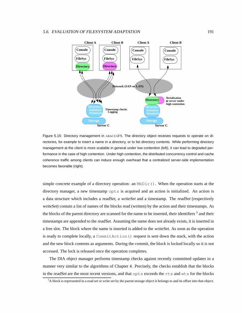
5.6. EVALUATION OF FILESYSTEM ADAPTATION 191
Storage Server C
T imestamp checks Logging Isolation
Storage
Server C
Atomicity
Dir ectory Sã
er ialization aä t server under high contention
Nå
etwork (SAN or LAN)
Client B
Dir ectory
FileSys
Console
Client A
Dir ectory
FileSys
Console
FileSys
Console
FileSys
Console
Client A Client B
Dir ectory Isolation Atomicity
Dir ectory
Figure 5.15: Directory management in ABACUSFS. The directory object receives requests to operate on di-
rectories, for example to insert a name in a directory, or to list directory contents. While performing directory
management at the client is more scalable in general under low contention (left), it can lead to degraded per-
formance in the case of high contention. Under high contention, the distributed concurrency control and cache
coherence traffic among clients can induce enough overhead that a centralized server-side implementation
becomes favorable (right).
simple concrete example of a directory operation: anMkDir(). When theoperation starts at the
directory manager, a new timestamp opts is acquired and an action is initialized. An action is
a data structure which includesa readSet, a writeSet anda timestamp. The readSet(respectively
writeSet) contain a list of namesof theblocks read (written) by theactionand their timestamps. As
theblocksof theparentdirectory arescannedfor thenameto beinserted, their identifiers3 and their
timestampsareappendedto thereadSet. Assuming thenamedoesnot already exists,it is insertedin
a freeslot. Theblock wherethenameis insertedis addedto thewriteSet. As soon asthe operation
is readyto completelocally, aCommitAction() request is sent down the stack, with theaction
and thenew block contentsasarguments. During thecommit, theblock is lockedlocally soit is not
accessed. The lock is releasedoncetheoperationcompletes.
The DIA object manager performs timestampchecks against recently committedupdates in a
manner very similar to the algorithmsof Chapter 4. Precisely, thechecksestablish that theblocks
in the readSetare themost recent versions,andthat opts exceedstherts andwts for theblocks3A blockis representedin areadsetor writesetby theparentstorageobjectit belongsto andits offsetinto that object.

192 CHAPTER 5. ADAPTIVE AND AUTOMATIC FUNCTION PLACEMENT
in the read and write sets. Note thatbecause clocks are loosely synchronized, a block’s wts and
rts need to bemaintainedonly for ashort timewindow (T), after which they canbediscarded and
logically replaced with the current time minusT. This may result in rejecting someoperationsthat
would otherwise be accepted but it will not result in incorrect operation. If thechecks succeed, the
new block contentsarecommittedto thelog andcallbacksarebrokento nodescaching thatblocks.
Otherwise, a rejection is returnedto thehost, who refreshesits cacheandretries the insert fromthe
beginning.
Dir ectory placement: Adapting to contention
The function placement problem involves a fundamental choice between the scalabili ty of client-
side execution whereCPU and memory resources aremore abundant and the potential network-
efficiency of server-side execution. In particular, it involvesa choice betweenreplicating function
across clients(which comesat thecost of higher synchronization overhead but which allows client
resourcesto beexploited) and centralizing it on a few nodes. Theplacement of directory manage-
ment functionexemplifiesthis trade-off anddemonstratesthat transparent monitoringcaneffectively
maketheproper trade-off in each case.
Filesystemfunctionality suchascaching or pathnamelookup, for example, is oftendistributed
to improve scalabili ty [Howardetal., 1988], as arefunctionsof other largeapplications. Synchro-
nization amongparallel clients is anoverhead which variesdepending on theamount of inter-client
contention overshareddata. Considertheexample of afile cachewhichisdistributed acrossclients.
Filesarestoredon theserverand cachedon clients. Furthermore,assumethat filesarekept coherent
by theserver. Whena client readsa file, the serverrecords thename of thefile and the client that
read it, promising theclient to notify it whenthe file is written. Whenanother clientwritesa file,
thewrite is immediately propagated to theserver, whichnotifies theclientsthathave thefile cached
that their version is now stale (via a “callback”) The clients thenaccessthe server to fetch the new
copy. This is how coherence is achievedin AFS[Howard etal., 1988] for example.
Now consider thecasewhereclients are accessing independent files,each write is propagated
to the server anddoesnot generateany “callbacks” becausethe file being written is cached only
at the client that is writing it. In this case, except for the initial invalidation message, there is no
furthercoherence-inducedcommunication from theserver to theclients. Thus,placing thecacheat
theclient doesnot induceany moresynchronization overhead than if it wasplaced at theserver.
On theotherhand, considerthecasewhere theclientsareall actively accessing,reading and/or

5.6. EVALUATION OF FILESYSTEM ADAPTATION 193
writing, thesame file. In this case,each write by a clientresults in “callbacks” to theactive clients,
who in turn contact the serverto fetch the recently written version of the block. Soon after that,
the sameclientor another client writesthe block again, causing a callback to bepropagated by the
server to therestof theclients. Theclientsthenre-fetch thenew copyof theblockthatwasupdated.
Under suchaworkload, placingthecacheattheclient causesexcessivesynchronization overheadin
the form of coherencetraffic (callbacks)anddatare-fetching. To sum up, theplacement of function
under certain workloads can have a dramatic impact on the amount of synchronization overhead,
and consequently theamount of network messaging. Theeffect of this overheadmust be weighed
against thebenefit of widerscalereplication (parallelization) of function.
Experiment. To validate this hypothesis, a few experiments were conducted. A workloadthat
performs directory inserts in a shared namespace waschosenasthe contention benchmark. This
benchmarkis more complicated than in thedistributed file caching case and therefore morechal-
lengingto ABACUS. Directoriesin ABACUS present ahierarchicalnamespacelike all UNIX filesys-
temsandareimplementedusingtheobject graphshown in Figure5.15. Whenclientsaccessdisjoint
parts of thedirectory namespace(i.e., there are no concurrent conflicting accesses), the optimistic
schemein which concurrency control checks are performedafter the fact by the isolation (DIA)
object works well. Eachdirectory object at a client maintains a cache of the directories accessed
frequently by that client, making directory reads fast. Moreover, directory updatesare cheap be-
causeno metadata pre-readsare required, andno lock messaging is performed. Further, offloading
from theserver thebulk of thework results in betterscalability and freesstoragedevices to execute
demanding workloads from competing clients. When contention is high, however, the numberof
retries and cache invalidations seenby the directory object increases,potentially causing several
round-trip latenciesper operation. Whencontention increases, thedirectory object should migrate
to the storage device. This would serialize client updatesthrough one object, thereby eliminating
retries.
Two benchmarks were constructed to evaluate how ABACUS responds to different levels of
directory contention. The first is a high contention workload, where four clients insert 200 files
each in a shareddirectory. Thesecond is a low contention workloadwhere four clients insert 200
fileseachin private(unique)directories.
Results. As shown in Figure5.16, ABACUS cutsexecution time for the high contention work-
loadby migrating the directory object to theserver. In theLAN case, ABACUS comeswithin 10%
of thebest,which is 8X better thanlocating thedirectory object at thehost. ABACUS comeswithin
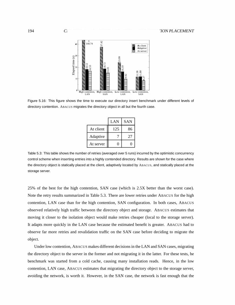
194 CHAPTER 5. ADAPTIVE AND AUTOMATIC FUNCTION PLACEMENT
37.
42
23.
99
11.
58
18.
12
18.
72
16.
10
11.
80 16.
53
15.
01
9.9
2
8.2
7
High contention,æ
LANHigh contention,ç
SANLow contention,è
LANLow contention,é
SAN
0ê
10
20ë30Ð40Ñ
Ela
psed
tim
e (s
)
At clientìAdaptiveíAt server
144.74
Figure 5.16: This figure shows the time to execute our directory insert benchmark under different levels of
directory contention. ABACUS migrates the directory object in all but the fourth case.
LAN SAN
At client 125 86
Adaptive 7 27
At server 0 0
Table 5.3: This table shows the number of retries (averaged over 5 runs) incurred by the optimistic concurrency
control scheme when inserting entries into a highly contended directory. Results are shown for the case where
the directory object is statically placed at the client, adaptively located by ABACUS, and statically placed at the
storage server.
25% of the best for the high contention, SAN case(which is 2.5X better than the worst case).
Notetheretry results summarizedin Table 5.3. There arelower retriesunder ABACUS for the high
contention, LAN case than for the high contention, SAN configuration. In both cases, ABACUS
observed relatively high traffic between the directory object and storage. ABACUS estimates that
moving it closer to the isolation object would makeretries cheaper (local to the storage server).
It adapts morequickly in theLAN case becausethe estimated benefit is greater. ABACUS hadto
observe far more retries and revalidation traffic on the SAN case before deciding to migrate the
object.
Underlow contention, ABACUS makesdifferent decisionsin theLAN andSAN cases,migrating
the directory object to the server in theformer and not migrating it in thelatter. For these tests, he
benchmark was started from a cold cache, causing many installation reads. Hence, in the low
contention, LAN case, ABACUS estimates that migrating the directory object to thestorage server,
avoiding the network, is worth it. However, in the SAN case, the network is fast enough that the

5.7. SUPPORTING USER APPLICATIONS 195
0 5 10 15
Elapsed time (s)î0
50
100
150
200
Cum
ulat
ive
inse
rts/
retr
ies
Cumulative retriesï
Cumulative insertsð
Migration timesñ
Figure 5.17: This figure shows the cumulative inserts and retries of two clients operating on a highly contended
directory over the SAN. Client 1’s curves are solid, while client 2’s are dotted.
ABACUS cost-benefit model estimatestheinstallation readnetwork cost to be limited. Indeed,the
results show that thestatic client and storageserver configurations for the SAN casediffer by less
than30%,thethreshold benefit for triggeringmigration.
Notethat clientsneednot agreeto migratethedirectory objectsto thestoragedeviceatthesame
time. They candecide independently, based on their migration benefit estimation. Correctnessis
ensured even if only someof the clients decide to move the object to the storage device because
all operations are verified to have occurred in timestamp order by the isolation object, which is
always presenton the storageservers. Figure 5.17 shows a time-line of two clients from thehigh
contention, SAN benchmark. The graph shows the cumulative number of inserted files and the
cumulative number of retries for two clients. Oneclient experiencesa sharp increasein retriesand
its objectismovedto theserver first. Thesecond happensto suffer fromarelatively low, but steady
retry rate,which triggersits adaptation a li ttle later. Thefirst client experiencesa sharp increasein
therateof progresssoonafter it migrates. Thesecondexperiencesasubstantial, but lower, increase
in its rateof progressafter it migrates, which is expected asstorageserver loadincreases.
5.7 Support ing userapplications
While the ABACUS systemfocussedon adaptive function placement in distributed filesystems, the
approach that it embodiescan in fact bereadily generalized to support adaptive functionplacement
for all stream-processing kinds of applications. This section describessomeexample applications
thatcan benefit fromadaptive function placement over ABACUS. In particular, it describes thecase
of adatafilteringapplication which wasportedto ABACUS. This sectionreportson itsperformance

196 CHAPTER 5. ADAPTIVE AND AUTOMATIC FUNCTION PLACEMENT
and implementation on theABACUS run-time. Thisdiscussion clarifieshow function placement can
begeneralizedbeyond the ABACUS filesystem to user-level applications, assumingthe underlying
filesystemis itself mobile.
5.7.1 Exampleapplication scenarios
There is a growing trendfor businessesto access a variety of servicesvia the web. There is a trend
even to host traditional desktopapplicationson remoteservers,at an“application serviceprovider”
(ASP).This movesthetasksof upgrade, maintenanceandstoragemanagement to theASP, reducing
the coststo theclient. On theother hand, streaming of real-time multimedia content customizedto
the user’s interestsis becoming commonplace. Such applicationsbenefit from adaptive placement
of their componentsdueto thewidevariabilit y in client-server bandwidthson theinternet and dueto
thegreat disparity in clientresources (PDAs to resourceful workstations) andin server load. As in-
vestments in the Internet’s infrastructurecontinue,bandwidth to theserver improves,andASPsand
content-rich applicationsbecome increasingly attractive and widespread. However, heterogeneity
will remainamajor challengefor application performancemanagement.
Distrib utedweb applications
ASPscan provide morerobust performanceacross workloadsandnetwork topologiesby partition-
ing function between theclient andthe server dynamically at run-time. Such a dynamic function
placementcanstill maintain the easeof management of server-side software maintenance, while
opportunistically shipping function to theclient whenpossible.
Customizedmultimedia reports
An increasing number of applications on the internet today compile multiple multimedia streams
of information, and customize these streamsto the needs of end users, their language, interests
and background. Such applications aggregatecontent from different sites, merge and filter this
information together and deliver it to the end client. The optimal placeto execute the different
functions on the dataset or stream depends on the kind of client used, e.g. a PDA or high-end
workstation, the current load on the server, andon the performance of the network between the
client and theserver. Dynamicpartitioning of functionbased onblackbox monitoring cansimplif y
theconfigurationof suchapplicationsoverwide areanetworksand heterogeneousclientandserver
pairs.
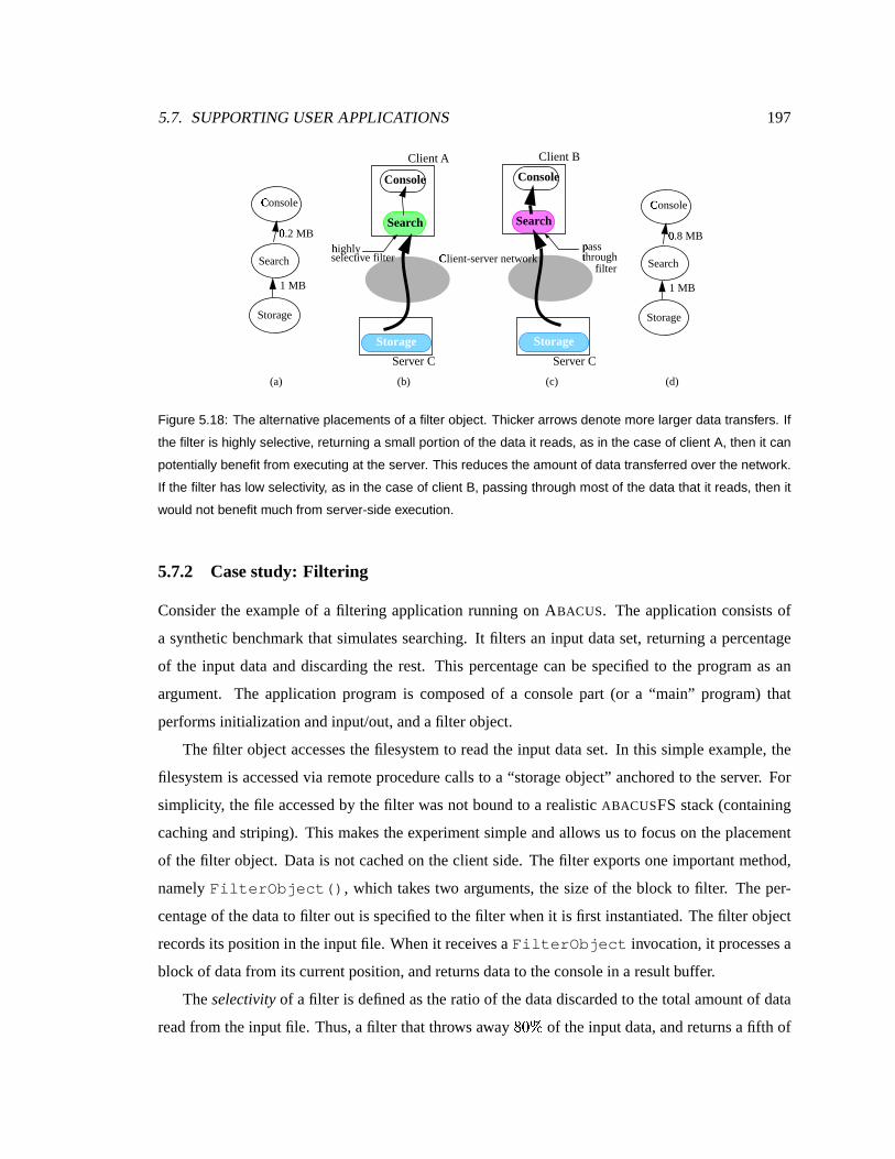
5.7. SUPPORTING USER APPLICATIONS 197
Storage
Server C
Cò
lient-server network
Client B
Sear ch
Console
Client A
Sear ch
Console
hó
ighly selective filter
pô ass tõhrough
Storage
Server C
(a) (d)
Storage
Search
Cò
onsole
1 MB
0ö
.2 MB
Storage
Search
Cò
onsole
1 MB
0ö
.8 MB
filter
(b) (c)
Figure 5.18: The alternative placements of a filter object. Thicker arrows denote more larger data transfers. If
the filter is highly selective, returning a small portion of the data it reads, as in the case of client A, then it can
potentially benefit from executing at the server. This reduces the amount of data transferred over the network.
If the filter has low selectivity, as in the case of client B, passing through most of the data that it reads, then it
would not benefit much from server-side execution.
5.7.2 Casestudy: Fil tering
Consider the example of a filtering application running on ABACUS. The application consists of
a synthetic benchmark that simulatessearching. It filtersan input dataset, returning a percentage
of the input data anddiscarding the rest. This percentage can be specified to the program asan
argument. The application program is composed of a console part (or a “main” program) that
performsinitializationand input/out, and afilter object.
Thefilter object accessesthefilesystem to readthe input dataset. In this simple example, the
filesystemis accessedvia remote procedurecalls to a “storageobject” anchored to theserver. For
simplicity, thefile accessed by thefilter wasnot bound to a realistic ABACUSFS stack(containing
caching and striping). This makestheexperiment simple and allows us to focuson theplacement
of thefilter object. Data is not cached on the client side. Thefilter exports one important method,
namely FilterObject(), which takestwo arguments, the size of theblock to filter. The per-
centageof thedatato filter out is specified to the filter when it is first instantiated. The filter object
recordsitsposition in theinput file. Whenit receivesaFilterObject invocation, it processesa
blockof datafrom its current position,and returnsdatato theconsole in a result buffer.
Theselectivity of a filter is definedastheratio of the datadiscarded to the total amount of data
readfrom theinput file. Thus,a filter that throws away ÷LøIù of the inputdata, and returnsa fifth of

198 CHAPTER 5. ADAPTIVE AND AUTOMATIC FUNCTION PLACEMENT
36.
24
4.8
2
40.
73
37.
12
8.5
5
2.0
2
40.
84
36.
13
6.9
1
1.3
8
73.
07
25.
66
High selectivity,ú
LANHigh selectivity,û
SANLow selectivity,ü
SAN,Loaded drive
Low selectivity,ý
LAN
0ê
20
40þ60ÿ80�
Ela
psed
tim
e (s
)
At clientìAdaptiveíAt server
Figure 5.19: The performance of the filter benchmark is shown in this figure. Executing the filter at the storage
server is advantageous in all but the third configuration, in which the filter is computationally expensive and
runs faster on the more resource-rich client.
it, hasa selectivity of ø��:÷ . Filterswith high selectivity fit the intuition of being “highly selective”,
choosing only a few from a largeset. Precisely: ���������� ��� �������� ����� ��� � ��� �!"� � ��# . Applications
can exhibit drastically different behavior basedon run-time parameters. This section shows that
the selectivity of the filter (which depends on the data set and the pattern being searched — a
programinput) determinestheappropriatelocationfor thefilterto run. For example, there’sadrastic
differencebetweengrep kernel Bible.txt and grep kernel LinuxBible.txt.
Experiment. Asdatasetsin large-scalebusinessescontinue to grow, an increasingly important
userapplicationishigh-performancesearch, or datafiltering. Filtering is generally ahighly selective
operation, consuming a large amount of data and producing a smaller fraction. A synthetic filter
object wasconstructed that returnsa configurable percentage of the input data to the object above
it. Highly selective filters represent ideal candidate for execution close to the data, so long as
computation resourcesareavailable.
In this experiment, both thefilter’s selectivity and CPU consumption were varied from low to
high. A filter labeled low selectivity outputs ÷Lø;ù of thedata that it reads, while a filter with high
selectivity outputs only 20% of its input data. A filter with low CPU consumption doesthemini-
mal amount of work to achieve this function, while a filter with high CPU consumption simulates
traversing largedatastructures(e.g.,thefinitestatemachinesof a text searchprogram likegrep).
Results. The filtering application starts executing with theconsole invoking the methodFil-
terObject(), exported by the filter object. As the application executes, data is transferredfrom
the storage object (the storageserver) to the filter (the client node), and from the filter to thecon-

5.8. DYNAMIC EVALUATION OF ABACUS 199
0 10 20 30 40$
50 60 70
Elapsed time (s)
0
1000
2000
3000
4000
Cum
ulat
ive
# of
blo
cks
proc
esse
dFilter 1%Filter 2%
Filter 1 movesto server&
Filter 1 move to client
Filter 2 moves to server
Figure 5.20: This figure plots the cumulative number of blocks searched by two filters versus elapsed time.
ABACUS’s competition resolving algorithm successfully chooses the more selective Filter 2 over the Filter 1 for
execution at the storage server.
sole. The ABACUS run-time system quickly accumulatesa history of the amount of datamoved
betweenobjects by recording the amount of datamoved in and out of an object. Thesestatistics
are updatedon procedure return from each object. Figure 5.18(a) and (c) illustrates the data flow
graphsconstructed by ABACUS at run-time in thecaseof two filterswith different selectivities.
Figure5.19showstheelapsedtimeto read andfilter a áKâÆ×�Ø file in anumberof configurations.
In thefirst set of numbers, ABACUS migratesthefilter from client to storageserver, coming within
25% of thebestcase,which isover5X betterthanfiltering attheclient. Similarly, ABACUS migrates
the filter in thesecond set. While achieving better performancethan statically locating thefilter at
the client, ABACUS reachesonly within 50% of thebest becausethetime requiredfor ABACUS to
migratetheobject isabigger fraction of total runtime. In thethird set, acomputationally expensive
filter was started. We simulate a loaded or slower storage server by making the filter twice as
expensive to run on thestorage server. Here, thefilter executes1.8X faster on theclient. ABACUS
correctly detectsthis caseandkeeps thefilter on theclient. Finally, in the fourth setof numbers, the
valueof moving is too low for ABACUS to deem it worthy of migration.
5.8 Dynamic evaluation of ABACUS
The previous section demonstrated thebenefitsof adaptive placement andshowed through several
microbenchmarks that ABACUS candiscover the best placement automatically under relative static

200 CHAPTER 5. ADAPTIVE AND AUTOMATIC FUNCTION PLACEMENT
workload and network conditions. This section evaluates the abili ty of ABACUS to adapt under
moredynamically varying conditions.
5.8.1 Adapting to competition over resources
Sharedstorageserver resourcesarerarely dedicatedto serving oneworkload. An additional com-
plexity addressed by ABACUS is provisioning storageserver resourcesbetween competing clients.
Toward reducing global application execution time, ABACUS resolves competition among objects
that would executemorequickly at theserver by favoring those objectsthat would derive a greater
benefit from doing so.
Experiment. In this experiment, two filter objects are startedon two Ù|Ú7×�Ø files on our LAN.
The filters have different selectivities, and hence derive different benefits from executing at the
storageserver. In detail, Fil ter 1 produces60% of thedata that it consumes,while Filter 2, being
the more selective filter, outputs only 30% of the data it consumes. The storageserver’s memory
resourcesare restricted sothatit canonly support onefilter ata time.
Results. Figure5.20 shows thecumulative progressof thefilters over their execution, andthe
migrationdecisionsmadeby ABACUS. The lessselectiveFilter 1 wasstarted first. ABACUS shortly
migrated it to the storageserver. Soon after, themore selective Fil ter 2 wasstarted. Shortly after
the second filter started, ABACUS migratedthe highly selective Filter 2 to theserver, kicking back
the other to its original node. The slopesof thecurvesshow that thefilter currently on theserver
runsfaster than whennot, but thatFil ter2 derivesmorebenefit sinceit ismoreselective. Filtersare
migrated to theserverafter anoticeable delay because in our current implementation, clientsdo not
periodically update theserverwith resourcestatistics.
5.8.2 Adapting to changesin the workload
Applications rarely exhibit the samebehavior or consumeresourcesat the samerate throughout
their lifetimes. Instead,anapplicationmay changephasesatanumber of pointsduringitsexecution
in responseto input from a user or a file or as a result of algorithmic properties. Such multiphasic
applicationsmakeaparticularly compelling case for the function relocation that ABACUS provides.
Experiment. Let’snow revisit our filecachingexamplebut make it multiphasic this time. This
cache benchmark does an insert phase, followedby a scanning phase, then aninserting phase, and
finally anotherscanphase.Thegoal is to determinewhether thebenefit estimatesat theserver will
ejectanapplication that changed its behavior after being movedto theserver. Further, we wish to
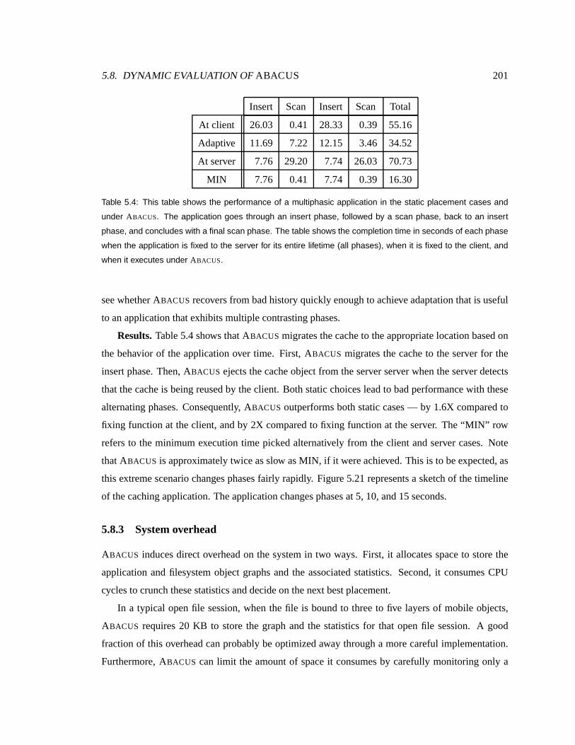
5.8. DYNAMIC EVALUATION OF ABACUS 201
Insert Scan Insert Scan Total
At client 26.03 0.41 28.33 0.39 55.16
Adaptive 11.69 7.22 12.15 3.46 34.52
At server 7.76 29.20 7.74 26.03 70.73
MIN 7.76 0.41 7.74 0.39 16.30
Table 5.4: This table shows the performance of a multiphasic application in the static placement cases and
under ABACUS. The application goes through an insert phase, followed by a scan phase, back to an insert
phase, and concludes with a final scan phase. The table shows the completion time in seconds of each phase
when the application is fixed to the server for its entire lifetime (all phases), when it is fixed to the client, and
when it executes under ABACUS.
seewhether ABACUS recovers from badhistory quickly enough to achieveadaptation that is useful
to an application that exhibitsmultiplecontrasting phases.
Results. Table 5.4shows thatABACUS migratesthecache to theappropriate location basedon
the behavior of the application over time. First, ABACUS migrates the cache to the serverfor the
insert phase.Then, ABACUS ejects the cache objectfrom the server server whenthe serverdetects
that thecacheis being reused by theclient. Both static choiceslead to badperformance with these
alternating phases. Consequently, ABACUS outperformsboth static cases— by 1.6X comparedto
fixing function at the client, andby 2X comparedto fixing function at theserver. The“MIN” row
refers to the minimum execution time picked alternatively from the client and server cases. Note
that ABACUS is approximately twiceasslow asMIN, if it wereachieved. This is to beexpected, as
this extremescenario changesphasesfairly rapidly. Figure 5.21 represents a sketch of thetimeline
of thecaching application. Theapplicationchangesphasesat5, 10, and15seconds.
5.8.3 Systemoverhead
ABACUS inducesdirect overhead on the system in two ways. First, it allocatesspaceto store the
application andfilesystem object graphs and the associated statistics. Second, it consumesCPU
cyclesto crunch thesestatisticsanddecideon thenext bestplacement.
In a typical openfile session, when the file is bound to three to five layers of mobile objects,
ABACUS requires20 KB to store the graph and the statistics for that open file session. A good
fraction of this overhead canprobably beoptimizedaway through a more careful implementation.
Furthermore, ABACUS can limit the amount of spaceit consumes by carefully monitoring only a

202 CHAPTER 5. ADAPTIVE AND AUTOMATIC FUNCTION PLACEMENT
0'
5(
10 15 20)
Elapsed time (s)*
0'
100
200+
300
400,
Pro
cess
ing
rate
At clientAdaptiveAt drive
Figure 5.21: This figure plots the processing rate in number of records per second for three configurations. In
the first configuration, the cache is anchored to the client, in the second, it is anchored to the server, and in the
third it is allowed to migrate under ABACUS. Because progress is measured at discrete time intervals as the
cumulative number of records processed, this graph can not be used to infer the exact times at which ABACUS
performed a migration from one node to the other.
subset of the open file sessions, thosethat move a lot of data, for example. For theother sessions,
the system can simply maintain summaryinformation such asthe total amount of data read from
the basestorageobjects. This summary information is necessary to discover open file sessions that
becomedata-intensive andpromote theminto astatewherethey are fully monitored.
TheABACUS run-timesystemalso consumesCPU cycleswhen the resourcemanageranalyzes
thecollectedgraphsto find out if a better placementexists. In theabove experiments, the ABACUS
resource manager wasconfiguredto wakeup onceevery 200 milli seconds and inspect thegraphs.
Theamount of overheadcan beconfigured by limiting thefrequency of inspections. Theobservable
overheadwhile executing applications in theabove experiments wasmostly within 10%. At worst,
it wasaslargeas25%in thecaseof short-livedprogramsfor which ABACUS-relatedinitializations
and statisticscollectionswerenot amortizedover a long enoughwindow of execution.

5.8. DYNAMIC EVALUATION OF ABACUS 203
0-
1 2.
3/
40
51
62
73
Time (seconds)
−1
−0.5
0-
0.54
1
1.5
2.
Cos
t/ben
efit
estim
ate
(sec
onds
)
Migration cost5Benefit estimate6Net benefit estimate7
Cost and benefit estimates for the synthetic filter(cost, benefit, net benefit and threshold values vs. time)8
Figure 5.22: Cost and benefit estimates versus time for the synthetic filter application.
5.8.4 Thresholdbenefit and history size
This section attempts to gain some insight into thedynamicsof the ABACUS cost-benefit estima-
tions. Consider the example of a highly selective filter application processing a 9 MB file, and
returning 20% of the datait reads. The next experiment starts the filter at the client and collects
and logsthecost andbenefit estimatescomputedby ABACUS. ABACUS wasdirectednot to invoke
any migrations although it continued to compute the required estimates. The client-server 10 Mb
Ethernet network was measured to deliver an approximateend-to-endapplication readbandwidth
of ø:�<; MB/s. Sincethe filtering application’s execution timewasdominated by server to client net-
work transfers, filtering a 4 MB file on the client required approximately 8 seconds. Performing
thefiltering on theserver would have requiredapproximately only 2 seconds(only = MB would be
transferredto theclient). Thus,thebenefit of server-sideexecution overclient-sideexecution for the
entireduration of theapplicationcan beapproximatedas > seconds,or �@?�; secondsper each second
of execution.
Figure 5.22 shows the estimatesof cost and benefit computed by the ABACUS run-time system
versustimeas theapplication executedon theclient. Notice that thebenefit afteran initial increase
flattened at about ø��@>A; seconds per second of execution. ABACUS approximated the benefit of
server-sideexecutionto beareduction of execution timeby �B>A; secondsovertheobservation history
window (of one second). This number correspondsto thevalue of CEDGFIH�H , computedby taking the
differenceof Equations5.4and5.3. ABACUS observed that theoutput of thefilterwasonly 20% of

204 CHAPTER 5. ADAPTIVE AND AUTOMATIC FUNCTION PLACEMENT
thesizeof thedatacurrently being communicatedover thenetwork. Using its estimatesof network
bandwidth, ABACUS computed thebenefit to be J �AK of the history window. This benefit value is
relatively closeto thevalueexpectedfrom theanalysis of thepreviousparagraph, or ø:�@? .Thefigure also plotsthecostof migration over time. Thecostof migration dependson thesize
of the state that mustbe transferred from the client to the server. As the filter executed, its state
increased and the cost accordingly increased. At somepoint (around L �MK ), the cost of migration
began to exceedthebenefit frommigration. Thisis becauseABACUS estimated thebenefit assuming
that theapplication wil l execute only for another N seconds. Longer history windows would have
allowedfor the benefit to behigher, overcoming theone-time migration cost and resulting in more
migrations. Longer history windows make the system slow to react to changesin theapplication,
however.
The figure also shows the net benefit from migration. The net benefit initially increasedand
thenstarteddecreasing as the cost of migration roseand the benefit remained flat. Note also how
the threshold benefitvalues, marked by thehorizontal dashedlines in thefigure,arekey to deciding
whether or not a migration occurs. In a setof migration experiments, the threshold value was set
to: ø��O=AP=ø"� K P8ø��<;�P=ø:�@? and ø��<Q . With threshold valuesof ø��<; and higher, no migrations occurred. This
is explainedby the plot of thenetbenefit estimatein the figure, which doesnot exceed ø:�<; , at any
timeduring execution.
5.9 Discussion
This section discusses somespecific aspects and limitationsof theABACUS prototypewhich were
not already sufficiently addressed.
5.9.1 Programming model and run-timesystem
Themereexistenceof mechanismsto changetheplacementof components,andthedevelopment of
anapplication according agivenprogrammingmodel doesnot always imply that run-timemobilit y
will improve application performance. The application should still be designedwith the goal of
better performancethrough mobilit y. Just like theuseof amodular programminglanguagedoesnot
imply a modular application, theavailability of mobility mechanismsdoesnot imply performance
gains. For instance, the run-time system can be overwhelmed with huge object graphs if the pro-
grammerchoosesto makeevery base type a migratable object. In this case, the run-time system

5.9. DISCUSSION 205
mustmove large subgraphs to generate any benefit and the overheadof themonitoring andplace-
mentalgorithmscanbecomeexcessive. Tools thatassist theprogrammersin properly decomposing
applications at the propergranularity would be helpful. For filesystems, thedecomposition is rel-
atively straight-forwardwith eachlayer in a stackable filesystem being encapsulated in an object.
For user applications, it is not aseasy.
Providing universalguidelinesfor thedesign of applicationswhichcanbenefit fromtheadaptive
placement of their components is challenging. More work on this question is needed. However, it
is clear that developing a tool thatassistsprogrammers in understanding resourceconsumption and
data flow through their programs can prove helpful in properly decomposing an application into
ABACUS objects.
ABACUS separatesresourcemanagementfrom monitoring andfrom method redirection mech-
anisms. It is therefore relatively simple to implement a different resourcemanagement policy. The
ABACUS benefit estimatesare based on the artificial assumption that the set of applications exe-
cuting during the observation window (of length N seconds) will execute exactly for another Nseconds. Equivalently, ABACUS assumes that history will repeat itself only for another N seconds-
longwindow. ABACUS discardshistory information beyond N secondsago. It alsodoesnotattempt
to estimate theapplication remaining execution time fromthesizeof thedataset, for example. The
algorithms used by ABACUS can be improved by more accurately estimating the remaining appli-
cation execution timeandby using old history information rather thandiscarding it.
The threshold benefit test employedby ABACUS migration algorithms is important becauseit
dampensoscillationsandhelpsmaskshort fluctuationsin resourceavailabili ty. A low threshold ben-
efit wil l makeABACUS chasesmallbenefitsthatmay not materialize. This canbebecauseABACUS
adapted too quickly to a short perturbation in network performancefor instance. In general, the
threshold benefit should be set such that it does not react to measurement or modeling error. If the
threshold benefit exceedsthe tolerance allowed for measurement and modeling errors, migration
will most oftenbeagooddecision.
5.9.2 Security
The ability of distributed applicationsto adaptively place their componentsat theserver opens the
potential for security threats. Mechanisms to protect against thesethreatsarenecessary to make
application andfilesystemreconfiguration possible. Thethreatsthatadaptivecomponent placement
createscan beorganizedinto four categories:

206 CHAPTER 5. ADAPTIVE AND AUTOMATIC FUNCTION PLACEMENT
R Applicationcompromising theserver. Theapplication canmaliciously compromisetheserver
by modifying its code, stateor other resources that theapplications should not access. The
resourcesthat canbe accessedby an application are: memory, filesystem, and thenetwork.
The safety of memory accesses can be controlled through Java, addressspaces, or interpre-
tation, for example. Rights in the filesystemcanbebeenforcedby ABACUSFS according to
its accesscontrol policy, as the server would if the application was making requests from its
homeclient. Accessto thenetwork ismadethroughtheoperatingsystem,and so in principle
doesnot poseany threatsto theserver(exceptfor denial of servicewhich is discussed below).
R Servercompromising theapplication. The server can also bemalicious and compromise the
application, by changing its code or state. This is a problem in the general casewhere the
server is someuntrusted remote node. In the context of this thesis, the server machine is
trusted, and it should besince it is storing andserving thedata to clients.
TheABACUS prototypeavoidsthesafetythreatsassociatedwithmigratingmaliciousorbuggy
application components to a server by running themin a separateaddressspace. Filesystem
componentsarelinked in with thefilesystemprocessrunning at theserver. Thecodeisguar-
anteednot to betampered with becauseit is directly readfromthefilesystem and notaccepted
fromaclient node.
R Applications compromising each other. One application that is remotely executing on the
server can accessstate of otherapplications and maymodify it. The samemechanismsused
to protect theserver’s resourcesfromtheapplication canbeusedto isolateapplicationsfrom
eachother.
R Denying server resources. An application canconsumeall theserver’s resources, rendering
it uselessto other applications. In ABACUS, this does not compromise the availability of
the storage server itself since the basic storage service runs at a higher priority then any
client-shipped code. However, an application might be designed to convince the run-time
systemto always select it for server-side execution over other competing applications. This
is conceivable in ABACUS becausethe resource management policy works towards global
reductionof execution timeacrossclientsandnot towards fairness.
Althoughany mobile object canmigrateto theserverand server consumeresources, ABACUS
can, in principle, restrict to which nodesa mobile object canmigrate throughthe useof un-
derlying storageserveraccesscontrol such asNASD capabili ties. NASDstorageserversmay

5.10. RELATED WORK 207
accept themigration of mobile objectsonly if they are authorizedby somewell-known and
trustedentity. ThisNASD managerentity canhandout unforgeablecapabili ties to themobile
objectsauthorizing themto useresourcesonagivenserver. If thecapability verification fails
in any specific migration, migration is refused.
5.10 Relatedwork
There exists a large base of excellent research andpractical experiencesrelated to code mobility
and and function placement in clusters. The ideaof function migration was introduced over two
decadesagoasa way to balanceload acrossmultiple CPUs in a system[Stoneand Bokhari, 1978,
Bokhari, 1979], and as a way to ensure continuous service availabili ty in the presence of system
faults [Rennels,1980]. Thissection briefly reviews this relatedwork.
5.10.1 Processmigration
Systemssuch as DEMOS/MP [Powell andMil ler, 1983], Sprite [Douglisand Ousterhout, 1991],
System V [Theimer etal., 1985] and Condor [Brickeret al., 1991] developed mechanisms to mi-
grateentire processes. Process migration is complex becausethe entire stateof a process, which
can be scattered throughout operating system datastructuresand the process’ own addressspace,
mustbe made accessible to theprocess on thenew node and thesemantics of all operationsshould
bethesamebefore, during, and after the migrations. The processstateincludesthe contents of its
addressspace (virtual memory), open files(open file entries andcachedblocks), communication
channels,and theprocessor’s state.
Processmigration can be enacted transparently to theprocessor canoccur through a process-
visible checkpoint/restore mechanism. Transparent processmigration hasbeen built using a com-
pletekernel-supported migration mechanism, or using only a user-level package. User-level im-
plementations tend to have limitedtransparency and applicabili ty, because they cannot achieve full
transparency. As well, they cannot make all the process’ statethat is embedded in the operating
system on thesourcenodeavailable on thetargetnodeaftermigration.
Transparent kernel-supported migration across heterogeneous platformsis even morecompli-
catedthanbetweenhomogeneous machines.Thecontents of theprocessvirtual memory cannot be
simply transferred to target node becausethe two machinesmay represent programs, numbersor
charactersdifferently. Evenif an executableversion of thecode to bemigratedis available for both
208 CHAPTER 5. ADAPTIVE AND AUTOMATIC FUNCTION PLACEMENT
architectures,accurately reconstructing thecontentsof theprocess’ addressspace in theabsenceof
datatypeinformation is acomplex and error pronetask[Chanchio and Sun,1998]. Most prior work
and all thesystemsdescribedhereassumehomogeneousclusters.
DEMOS/MP
The DEMOS/MP distributed operating system is one of the earliestoperating systems to provide
kernel-supported transparent processmigration [Powell andMil ler, 1983]. TheDEMOS operating
system uses theabstraction of linksto implement communicationbetweenprocessesandbetweena
processand theoperatingsystem.
This nice abstraction enablesthe operating system to enact migration elegantly. All commu-
nication with a processoccurs through links. Thus, adding support for location transparency is
focussed on making link behavior independent of the node. A link is attached to a processand
not to a node. Thus,after the processmigrates, thecommunication subsystem correctly forwards
the messagesto thenew process. Becauseall system calls use links, this mechanism provides the
required transparency.
Spri te
Location transparency is an original design goal of Sprite [Douglis andOusterhout, 1991]. For ex-
ample, Sprite includesa highly location transparent network filesystem. Yet, transparent migration
still proveddifficult even in thecaseof openfilestatein this location-transparent network filesystem.
Open fileshave threekindsof stateassociated with them: cacheddata, afileposition, andafile
reference. Becausethestateassociatedwith anopenfile is copiedfrom sourceto target, it is shared
across nodes. This sharing is thesourceof the problem. The Sprite file server has a policy where
it disables file caching whena file is openfor writing by more thanonenode. In suchcases,writes
are propagated immediately andlessefficiently to the server. When a processis migrated, its files
all appear to beopen by sourceanddestination, causingcaching to bedisabled. Alternatively, if the
file is first closedat thesourcenode, it canbeincorrectly deleted, if it is a temporary file, which is
to be immediately removed on close. These issues were overcome but required Sprite to develop
complex modificationsto migration and to theoperatingsystem.
Sprite associatesa home node with each processwhich is the machine where the process was
started. System calls thatdependon the location of a process areforwardedto theprocess’s home
node. As long as the number of thesesystem calls is small, the impact of this forwarding on

5.10. RELATED WORK 209
performance may be acceptable. fork and exec are examples of expensive system calls that
mustbe forwardedto thehomenode.
Systemslike theV kernel, DEMOS, andAccent[Richard Rashid, 1986], where all interactions
with a process, including OSsystem calls, occurred through a uniform communication abstraction,
can elegantly enact migration by making the endpoints of their communication channels location
transparent. Messageswereforwardedto thenew location aftermigration. Sprite,ontheother hand,
allowedprocessesto interact with theoperating systemthrough traditional systemcalls which re-
quired lesselegant, albeit often moreefficient, operating systemsupport. However, both approaches
require someform of rebinding after migration. For example, if a processwants direct accessto a
hardware resourceon thenodeit is runningon, its request cannot beforwardedto itshomenode. It
is sometimeshard to know which nodetheprogrammerwantsasystemcall to effect.
Condor
While kernel-supported processmigration canbetransparent to user processes, it hasnot achieved
widespreadacceptancein commercial operatingsystems.I believethecomplexity of kernel-supported
migration and the lack of strong demand for it so far hasdiscouraged its commercial inclusion.
While there is significant demands for processmigration for thepurposeof exploiting idle worksta-
tion resources in clusters, this demand is satisfiedby simpler user-level migration implementations
such as Condor and the Load Sharing Facility [Brickeret al., 1991, Zhouet al., 1992], or through
application-specific mechanisms[Noble etal., 1997].
Theapproach to processmigration that gainedcommercial successis theless transparentuser-
level implementation, of which Condor is a good example [Brickeret al., 1991]. Condor employs
threeprinciple mechanisms to provide the load balancing in a cluster: Classified Advertisements,
RemoteSystem Calls, and JobCheckpointing. ClassifiedAds are the mechanism thatCondor uses
to pair up Resource Requestsand ResourceOffers. Remote system calls redirect thesystemcalls
of the new copy of the processto a shadow process running on the user’s local workstation. The
system calls are executedon the local workstation by theshadow, and the results are sent back to
the application on the remoteworkstation. This enablesCondor to migrate a process to a remote
workstation that doesnot have all the capabilit ies of the original workstation. For example, the
remote workstation may have ample CPU cycles but no access to a network filesystem that the
application usesto storefiles.In this case,after migration, thefileaccesssystem calls aresent back
to beservicedat theoriginal nodeby theshadow (vestigial) process.
210 CHAPTER 5. ADAPTIVE AND AUTOMATIC FUNCTION PLACEMENT
Checkpointing in Condor is performed through checkpointing and restart libraries linked to
with the process. Whena process is to be migrated,Condor sends a signal which is captured by
the checkpointing library. This library contains code that saves the virtual memory contents of
the process to be usedto reinitialize the new process on the target node. Because Condor is a
totally user-level implementation, it ismuch less transparent than kernel supportedapproaches.For
instance,forking and processgroupsarenot supported.
The research described in this chapter addresses the problem of migrating application objects
that are usually of finer granularity than entire processes. Rather than focusing on the migration
mechanism, ABACUS asks for thehelp of theprogrammer in abiding to a programming discipline
that simplifies migration. The focusin ABACUS is insteadon where to place components and how
to dynamically adjust thisplacement.
5.10.2 Programming systemssupporting object mobility
Mobile object systemsareprogramming systemswhere objects can move betweennodestranspar-
ently to the application programmer. A seminal implementation of object mobilit y is demonstrated
by Emerald [Julet al., 1988].
Emerald is a distributed programming languageand system which supports fine-grainedobject
mobilit y [Jul etal., 1988]. Emerald providesauniform object model, whereeverything in theappli-
cation is anobject. Built-in types(integers,floats), aswell asarrays and structs are objects. Object
invocation is location transparent and hasthesame semantics in both local andremote cases. An
Emerald objectconsists of a name, which uniquely identifies the object, a representation, which –
except for thecase of primitive types– consists of references to other objects, a set of operations
(an interface), and anoptional process, which is started after the object is createdand executesin
parallel to invocationson theobject. Emerald doesnot support inheritance.Objects in Emerald are
derived from abstract data types, canbe either passive or active and can be passed as arguments
to method invocations. Active objectsare associated with a processthat is startedafter theobject
is createdand executes concurrently to the invocationsperformed on theobject. To ensure proper
synchronization betweenconcurrent invocationsand the internal, active process,Emerald offers its
programmersmonitorsandcondition variables.
Emerald implementsdatamigration throughacombinationof by-copy, by-moveandby-network-
referencemechanisms. Local referencesarechanged tonetwork referenceswhenanobject migrates.
For immutable objects, however, Emeraldusesdatamigrationby copy. Theobjectscanbedeclared
5.10. RELATED WORK 211
as“immutable” by the programmer (i.e. the values of the fields in the object do not change over
time), in which case they arefreely copiedacrossthe network simplify ing sharing. An object of a
built-in type that is passedasanargument to a remoteobjectmethod is alsocopied.
Other objects aresent asnetwork references. Since an invocation to a remote object canpass
several other local objectsas arguments, performancecandegrade if the argument objectsare not
moved to the target node. Emerald supports call-by-move semantics where argument objects are
migrated to the target node hosting the invoked object. This can be specified by the programmer
using special keywords. Whenanobject is moved, its associatedmethodsand statemust bemoved
with it.
ABACUS uses similar mechanismsto thoseproposedin Emerald to find mobile objectsat run-
time. While Emerald enablesobjectmobili ty betweennodes,ABACUS focuses on the complimen-
tary problemof deciding where to locateobjectswithin acluster.
5.10.3 Mobileagent systems
Recent work in mobile agents has proposed a different programming model to support explici t
application-supported migration [Dale,1997, Grayet al., 1996, Chessetal., 1997, Knabe, 1995].
The growth of the internet has recently catalyzedresearch on languagesandrun-time systemssup-
porting “mobile agent” applicationswhereanagent “roamsaround” thenetwork, moving fromone
site to another performing somecomputation at eachsite. An example of a mobile agent is a pro-
gramthatsearches for thecheapestairfarebetween two citiesby crawling from oneairline’s site to
the next. Mobile agents areattractive in that they cansupport “spontaneous electronic commerce”
[Chessetal., 1997], electronic commercetransactionsthat do not require theprior agreement or co-
operationof thesitesinvolved. Computationscanroamthenetwork choosing their path dynamically
and freely. Mobile agents raise security issuessincea server is usually nervous about accepting an
agent without knowing its intentions.
Theeleganceandwiderangeof thepotential applicationsof mobileagentshaveresultedin sev-
eralmobileagent programmingsystems[Dale, 1997, Gray, 1996,Hyltonet al., 1996,Straeretal., 1996,
Acharya etal., 1997, Bharatand Cardelli, 1997]. Mostsystemsareobject-basedalthoughsomeare
scripting languageswith support for migration.
Mobile agents, like ABACUS, use explicit checkpoint/restore methods to save andre-
store their statewhen they migrate. However, while mobile agents are responsible for deciding
where they should executeandwhenthey should move fromonenodeto another, mobile objects in

212 CHAPTER 5. ADAPTIVE AND AUTOMATIC FUNCTION PLACEMENT
ABACUS delegatethatresponsibili ty to theABACUS run-timesystem.
5.10.4 Remoteevaluation
Traditional distributedapplicationsstatically partition function betweenclient and server. Applica-
tion programmers decide on this function partitioning at design-time by fixing the “programming
interface” to the server. The list of remote procedure calls (RPC) implemented by the server is
therefore fixed at design-time. Clients build applications by building on the servicesprovided by
the servers. Applications that arenot well-matchedwith this division of labor betweenclient and
serversuffer from inefficientperformance.
Consider the example of a distributed filesystem. The server providesprocedures to insert a
new file and deleteanexisting file fromahierarchical tree-likenamespace.It also providesa lookup
procedurewhich returnsthecontentsof adirectory (all thefilesthat exist in thatdirectory). Thenew
file nameand theparent directory arespecified asarguments to theinsert procedure. The filename
of the existing file andthe parent directory are specified asarguments of thedelete procedure. A
lookup procedure call takesthe parent directory asanargument andreturnsits contentsasa result.
Now consideraclient that desiresto deleteall fileswith a “.tmp” extension in thenamespace.This
client is required to issuea large numberof successive RPCs, to lookup all the directories in the
namespaceandthento delete,oneRPCata time, thematching files. In such ascenario, it would be
moreefficient to send the“deletesubtree” programto theserverand executeit there and avoid this
excessiveclient-server communication.
Remote evaluation [StamosandGifford, 1990] is a more general mechanism to program dis-
tributed systems. It allows a node to send a request to another nodein the form of a “program”.
Thedestination nodeexecutes the program andreturns the results to thesource node. While with
remote procedure calls, server computers are designedto offer a fixedsetof services, remote eval-
uation allows servers to be dynamically extended. Remote evaluation can usethe sameargument
passing semantics asRPCs,and masks computer and communication failuresin the sameway. It
can also provide for a static checking framework to identify “programs” that cannot be sent to a
givennodefor execution, althoughin general this is very hard to do without significant restrictions
on theprogramming model.
Stamos’ Remote Evaluation allows flexibility in the placement of function (execution of ser-
vices) in a fashion similar to ABACUS. However, it doesnot provide an algorithm or suggest a
framework which allows this placement to be automatically decided. The programmer decides

5.10. RELATED WORK 213
whento invokeaservice locally and whento ship it to a remotenode. A filesystem built onRemote
Evaluationwould require thefilesystemprogrammer to think about whento do local versusremote
execution.
5.10.5 Active disks
A growing number of important applicationsoperateon largedatasets,searching,computing sum-
maries,or looking for specific patterns or rules, essentially “filtering” thedata. Fil ter-li ke applica-
tionsoftenmakeoneor moresequential scansof thedata[Riedel etal., 1998]. Applicationsexecute
on the host, with thestoragedevice serving asblock servers. Activedisk systemsclaim that thein-
creasing levels of integration of on-disk controllers arecreating “excess” computing cycleson the
on-disk processor. Thesecyclescanbeharnessedby downloading“application-specific” datainten-
sive filters. Currently, data-intensive applicationsexecute entirely on the host, oftenbottlenecking
on transferringdatafrom thestoragedevices(servers) to thehost (client in this case).
Recently, considerable interest has been devoted to the “remote execution” of application-
specific codeon on-disk processors. Several systems have been proposed such asactive and in-
telligent disks [Riedel etal., 1998, Keeton etal., 1998, Acharyaet al., 1998]. Remote execution is
especially appealing for data-intensive applications that selectively filter, mine, or sort large data
sets. Active disksthus proposeexecuting the data intensive function of an application on the on-
diskprocessor.
Acharya et al. [Acharyaetal., 1998] proposea stream-based programming model, where user-
downloaded functionsoperateon datablocksasthey “streamby” fromthedisk. Oneproblem with
this stream-based model is coherenceof data cached by applicationsexecuting on thehost. Since
data canpotentially bereplicated in thehostand in theon-disk memory, consistency problemscan
arise. Moreover, this programming model is quite restrictive. For instance, to limit the amount
of resources consumedby downloaded functions, user-downloaded functions aredisallowed from
dynamically allocatingmemory.
Active disks delegate to the programmer the task of partitioning the application. In the best
possiblecase,thequery optimizer-like engineis used to partition functionsbetweenhost andactive
disk [Riedel, 1999]. While query optimizers usea-priori knowledge about the function being im-
plementedto estimatewhatpartitioning isbest,ABACUS usesblack-box monitoring which is more
generally applicable albeit at thecostof higher run-time overhead.
214 CHAPTER 5. ADAPTIVE AND AUTOMATIC FUNCTION PLACEMENT
5.10.6 Application object par titi oning
Coign [Hunt and Scott, 1999] is a system which optimizes the partitioning of objects in a multi-
object application executing overaclusterof nodes. It tracesthecommunicationsof theapplication
during someinitial executionsandusesthis to decidewhereeach object should live. Coign doesnot
allow objects to move after theapplication starts. Whentheapplication starts,objectsareanchored
to their locations. Coign relieves the programmer from allocating resourcesanddeciding object
placementat design time. Coign employs scenario-based profiling and graph-cutting algorithms
to partition application objects in a distributed component application between nodesof a cluster.
Coign focuseson finding theproper initial placement of objectsat installation time. It usesbinary
rewriting techniques to collectstatisticsabout inter-object communication when a typical workload
is appliedto thesystem which arethenusedto decideontheproperplacement of component objects
giventheavailability of CPU andnetwork resources.
Coign doesnotperform run-timemonitoringor preemptivemigration of component objects. Its
placementalgorithmsareexecuted off-l ineand thereforehaverelatively forgivingresponsetimere-
quirements. On theotherhand, Coign enablesoptimizationof function placement at thegranularity
of an object, and not the granularity of entire processes. In the presence of a “typical scenario”,
Coign canbe very effective in improving performance. However, when the proper placement de-
pends on invocation-time parameters or on dynamicchangesin resource availability, this approach
can besuboptimal.
River [Arpaci-Dusseau etal., 1999] is a data-flow programmingenvironment and I/O substrate
for clustersof computers. It is designed with the goal of providing maximum performance in the
commoncasedespiteunderlyingheterogeneity innoderesourcesanddespiteotherglitchesandnon-
uniformitiesthat might affect node performance. River balances load acrossconsumersof a data
set using a distributed-queue. River effectively balancesload by allocating work to consumersto
match their currentdataconsumption rates. This ensuresloadbalancing acrossmultipleconsumers
performing the same task. This research complements River by addressing the caseof multiple
concurrenttasks.
The closest previous system to the approach takenby this dissertation is Equanimity. Equa-
nimity dynamically rebalancesservicebetweenaclient and its server[Herrin, II andFinkel, 1993],
using heuristics basedon theamount of data communicated betweenfunction. Equanimity did not
consider theimpact of function placement on load imbalanceandusedonly simplecommunication-
based heuristics to partitioning thegraph of function between aclient andits server.
5.10. RELATED WORK 215
This research builds on Equanimity by considering service rebalancing in more realistic en-
vironments which exhibit client competition, data-intensive applications layered atop filesystems,
heterogeneous resourcedistributionsand shared datacomputing.
5.10.7 Databasesystems
Database management systems must often provide stringentguaranteeson transaction throughput
and maximum latency. Databasemanagement systemsinclude a query optimizer which compiles
a query in a structured high-level language onto an execution plan which is carefully selected to
maximizea givenperformance goal. Query optimizers decidewhat part of the query to execute on
which nodeby consulting arule-based system or apredictiveperformancemodel. Theseapproaches
apply effectively to relational queriesbecausethereis a limited number of query operators and the
operatorsareknown to theoptimizeraheadof time.
Traditional relational databasesystem arebased on a “ function shipping” approach. Clients
submit entire queriesto theserverswhich execute thequery and return theresults. Object-oriented
databasesystemareoftenbasedona“datashipping” approachthat makesthemsimilartodistributed
filesystems.Dataistransferredfromtheserversto theclient whereit is cached.Queriesareexecuted
on this datalocally at theclient. While datashipping is more scalable in principle becauseit uses
client resources,network efficiency oftenmandatesa function shipping approach.
Hybrid shipping [Franklin etal., 1996] is a technique proposedto dynamically distribute query
processing load between clients and serversof a databasemanagement system. This technique
usesa priori knowledgeof thealgorithms implementedby the query operators to estimate thebest
partitioning of work betweenclientsandservers. Instead, ABACUS appliesto awiderclassof appli-
cationsby relying only on black-box monitoring to makeplacement decisions, without knowledge
of thesemanticsor algorithms implemented by theapplication components.
Onewaytoview ABACUS researchis thatit attemptstobridgethegapbetweendatabasesystems
and filesystemsby bringing the benefits automatic resource management capabilitiesof database
query optimizersto the applicationsthat usefilesystemsand other object stores. Unlike database
query optimizers, ABACUS uses a generic mechanism basedon monitoring inter-object communi-
cation and object resourceconsumption to help it predict theoptimal placement.

216 CHAPTER 5. ADAPTIVE AND AUTOMATIC FUNCTION PLACEMENT
5.10.8 Parallel programming systems
Many programminglanguagesand systemshave recently investigated ways to improve the locality
of dataaccessesfor parallel applicationsincluding [AmarasingheandLam,1993,Hsieh etal., 1993,
Chandraetal., 1993, CarlisleandRogers,1995]. For example, Olden[Carlisle and Rogers, 1995]
and Prelude [Hsiehetal., 1993] attempt to improve locality by migrating computations to the data.
A computationaccessingdataonaremotenodemay bemoved to that node. COOL [Chandraetal., 1993]
is a parallel languagewith a scheduling algorithm that attempts to enhancethelocality of thecom-
putation while balancing the load. COOL providesan affinity construct that programmersuseto
providehints that drive thetaskschedulingalgorithm.
The research in this chapter builds on this previous work by applying such techniquesto the
caseof storage-intensiveapplications. Storage-intensiveapplicationscanbeeffectively modeledby
a timed dataflow graph which canbe usedto make effective placement decisions. Moreover, such
applicationsmove a largeamount of data allowing a run-time systemto learn valuable information
about inter-object communication and object resource consumption quickly, and judiciously use
it to select the best placement possible. Furthermore, this research is the first, to the bestof our
knowledge, to apply thesetechniquesto the caseof a particular and important systemapplication,
namelyadistributedfilesystem.
5.11 Summary
Emerging active storage systemspromisedramatic heterogeneity. Active storage servers—single
disks, storage appliancesand servers—have varied processor speeds, memory capacities, andI/O
bandwidths. Client systems—SMP servers, desktops, and laptops—also have varied processor
speeds, memory capacities, network link speeds and levels of trustworthiness. Application tasks
vary their loadover timebecauseof algorithmicor run-timeparameters. Most importantly, dynami-
cally varyingapplication mixesresult fromindependent andstochastic processesatdifferentclients.
These disparities make it hard for any design-time “one-system-fits-all” function placement deci-
sion to provide robustperformance. In contrast,a dynamicfunction placement scheme can achieve
better performanceby adapting to application behavior and resourceavailabilit y.
Previous systems demonstrated different function placement decisions, accentuating the fun-
damental trade-off between the scalabilit y of client-side execution and the network efficiency of
source/sink-side computing. However, due to thevariability in application resource consumption,
5.11. SUMMARY 217
in application mixesand in cluster resourceavailabili ty, thetensionbetweenscalability and source-
sink computing cannot be easily resolved until run-time. This chapter presents an overview and
evaluation of ABACUS, an experimental prototype system used to demonstrate the feasibili ty of
adaptive run-time function placement betweenclients and serversfor filesystem functions aswell
asstream-processing typeof applications. ABACUS uses analgorithm that continuously monitors
resource availabili ty aswell asfunction resource consumption and inter-function communication
and usesthis knowledge to intelligently partition function betweenclient and server.
This chapter describes a distributed filesystem,ABACUSFS, portedto the ABACUS systemand
reports on its ability to adapt. Microbenchmarks demonstrate that ABACUS and ABACUSFS can
effectively adapt to variations in network topology, application cache accesspattern, application
data reduction (filter selectivity), contentionovershareddata,significant changes in application be-
havior at run-time,aswell asdynamiccompetition fromconcurrent applicationsover sharedserver
resources. Microbenchmark results arequite promising; ABACUS often improvedapplication exe-
cution timeby afactor of 6 or more. Under all experiments in thischapter, ABACUS selects thebest
placement for eachfunction, “correcting” placement if function wasinitially started onthe“wrong”
node. Under more complex scenarios, ABACUS outperforms experiments in which function was
statically placed at invocation time, converging to within 70% of themaximum achievable perfor-
mance. Furthermore,ABACUS adaptsplacementwithout knowledgeof thesemanticsimplemented
by theobjects. The adaptation is based only on black-box monitoring of theobject and thenumber
of bytesmovedbetweenobjects.

218 CHAPTER 5. ADAPTIVE AND AUTOMATIC FUNCTION PLACEMENT

Chapter 6
Conclusionsand futurework
This chapter concludesthis dissertation by summarizing the maincontributions and describing di-
rectionsfor futurework. It isorganized asfollows: Section6.1summarizestheresearchreportedon
in this dissertation. Section 6.2 highlights the maincontributions. Section 6.3discussesdirections
for futurework.
6.1 Dissert ation summary
6.1.1 Network-attachedstorage
Storage bandwidth requirements continue to grow due to rapidly increasing client performance,
new, richer content data types such as video, anddata intensive applications suchasdata mining.
This problem hasbeenrecognized for at least a decade [Longet al., 1994, Pattersonet al., 1988,
Hartman and Ousterhout, 1993]. All storagesystem solutions to date incur a high overhead cost
for providing bandwidth due to existing storage architectures’ reliance on file serversas a bridge
betweenstorageand client networks. Such storage systemsdo not scale because they rely on a
central controller to manageandmediate accessto the physical storagedevices. Requestsfrom the
application all passthroughthestoragecontroller, which then forwardsthemto thestoragedevices,
storingandcopying data through it onevery access. Storagesystemsadministratorsexpandstorage
capacity by using multiple underlying disk arrays, and partitioning thedata set manually between
thearrays. Unfortunately, even if load balancing wasagooduseof time,thesystemadministrator is
rarely well equipped with thedynamic information to perform balancingin atimely and satisfactory
manner.
Storagearchitecturesare ready to change asa result of the synergy from four overriding fac-
tors: increasing object sizesand data ratesin many applications, new attachment technology, the
219

220 CHAPTER 6. CONCLUSIONSAND FUTURE WORK
convergenceof peripheral and interprocessor switched networks, and an excessof on-drive tran-
sistors. Network-Attached Secure Disks(NASD) [Gibson etal., 1997b, Gibsonetal., 1998] is an
architecture that enables cost-effective bandwidth scaling. NASD eliminatestheserver bottleneck
by modifying storagedevicesso they can transfer data directly to clients. Further, NASD reparti-
tionstraditional file server functionality betweentheNASD drive,client andserver.
NASD doesnot advocate that all functions of the traditional file serverneed to be or should
be migrated into storage devices. NASD devicesdo not perform the highest levels of distributed
file system function — global naming, access control, concurrency control, andcache coherency
— which definesemanticsthatvarysignificantly acrossdistributedfilesystemsand to whichclient
applications and operating systemstightly bind. Instead, the residual file system, which is called
the file manager, continues to define andmanagethesehigh level policies while NASD devices
implement simple storageprimitivesefficiently andoperateasindependently of thefile manageras
thesepolicies allow. The low cost of storage is due to the large marketfor mass-produced disks.
This massproduction requires a standard interface that must be simple, efficient, and flexible to
support a wide rangeof file system semantics acrossmultiple technology generations.
NASD enablesclients to perform parallel data transfersto and from thestoragedevices. This
dissertation describesastorageservice,Cheops,which implementssuchfunction. Real applications
running on top of a Cheops/NASD prototypereceive scalable dataaccessbandwidths that increase
linearly with system size. For a Cheops client to conduct parallel transfers directly to and from
the NASD devices, it must cache the stripe maps and capabilit ies required to resolve a file-level
accessandmapit onto accessesto thephysical NASDobjects. TheCheopsapproachis to virtualize
storagelayout in order to makestoragelook more manageable to higher-level filesystems. Cheops
avoids reinlisting servers to synchronously resolvethevirtual to physicalmapping by decomposing
and distributingitsaccessfunctionsandmanagement functionssuchthataccessfunctionisexecuted
at the clientwhere the request is initiated. Cheopsmanagersare responsible for authorization and
oversight operationssothattheparticipating clientsalwaysdo theright thing.
6.1.2 Sharedstoragearrays
For thesake of scalability, Cheopsallows clients to accessshareddevices directly. This fundamen-
tally makeseachstorageclient astoragecontroller on behalf of theapplications runningon it. Each
storagecontroller can serve clients and managestorage. Unfortunately, such sharedstoragearrays
lack a central point to effect coordination. Because datais striped acrossseveral devicesand often

6.1. DISSERTATION SUMMARY 221
NS
etwork ST
witched
U�V�WU�V�WXAY Z [B\^]S
Ttorage
SC
C_
ontroller
ST
CSI bus (`I/O bus)
(`a) T raditional storage systems (
`b) Scalable storage arrays
C_
lients U�V�W
. . . X Y Z [@\^]
XAY Z [B\^]C_
lients
XAY Z [B\^]
XAY Z [B\^]
XAY Z [B\^]ST
torage C_
ontrollers
Parallel
Figure 6.1: Traditional storage systems (a) use a single controller. Shared arrays (b) use parallel cooperating
controllers to access and manage storage.
stored redundantly, a single logical I/O operation initiated by an application may involve sending
requeststo several devices. Unless proper concurrency control provisions are taken,theseI/Os can
become interleaved sothathostssee inconsistent dataor corrupt the redundancy codes.
This dissertation proposesandevaluatesan architecture that enables the controllersto concur-
rently access shareddevices, migrate data betweendevices, and reconstruct dataon failed devices
whileensuring correctnessand recovering properly fromfailures. Thedifficult aspectof this task is
to ensure that the solution is scalable, thereby delivering thescalability of theNASD architecture.
The proposedapproach is to avoid central global entitiesand opt for distributing control overhead
instead.Both concurrency control and recovery protocolsaredistributed. Specifically, theapproach
proposesbreaking storageaccessandmanagement tasks into two-phasedlight-weight transactions,
called base storagetransactions(BSTs). Distributedprotocols are used to ensureconcurrency con-
trol and recovery. These protocols do not suffer from a central bottleneck. Moreover, they exploit
the two-phased natureof BSTs to piggy back control messagesover data I/Os,hiding control mes-
saging latency in thecommon case.
The base protocols assume that within the shared storage array, data blocks are cached at the
NASD devices and not at the controllers. When controllers are allowed to cachedataand parity
blocks, the distributed protocols can be extended to guaranteeserializabilit y for reads and writes.
This dissertationdemonstrates that timestamporderingwith validation performsbetter than device-
servedleasing in thepresenceof contention, falsesharingandrandom accessworkloads, all typical
of clustered storage systems. In summary, it concludes that timestampordering based on loosely

222 CHAPTER 6. CONCLUSIONSAND FUTURE WORK
SAN Client
LAN client
Sa
witched
LAN
W AN
Wb
Ac
N client
Sa
AN
Data servers (sources)
- File servers (A)
- Smart Storage (D)
- Sensors/Cameras (C)
. . . - Clustered Server (B)
dBegf hiegfdBegf hiegfdBegf hiegf
Cj
PU
Ak
vailable memory
Sl
torage access bandwidth (mto server B’s data)
Jnava
Figure 6.2: Emerging systems include programmable clients and servers. However, the clients and the servers
vary in their computational and memory resources. The optimal partitioning of function between client and
server varies based on run-time characteristics such as node load, network bandwidth, and amount of com-
munication between application components. This figure shows the available CPU and memory resources
on some of the nodes. The available access bandwidth between a node and the storage on server B is
also graphed. Assume a generic computation over a data set streaming out of server B, where should the
computation be performed (client or server?).
synchronizedclocks has robust performanceacrosslow andhigh contention levels, in the presence
of device-side or host-side caching. At thesametime, timestampordering requireslimitedstate at
thedevicesanddoesnot requirethedevicesto perform anyextramessagingon behalf of hosts(such
aslease revocation).
6.1.3 Dynamic and automatic function placement
Another challenging aspect of storage management concerns the proper partitioning of function
betweenthedifferent nodes in thestoragesystem. Thepartitioning of function between client and
server has a direct impact on how load is balanced among a server and its clients and on how
much data is transferred betweenclient and server. Naive placement can cause resources to go
underutili zedandloadto be imbalancedor largeamountsof datato be transferred(unnecessarily )
over bottlenecked links.
Currently, the partitioning of filesystem function between client and server is decided by the
application programmer at design time. Filesystems designersdecide on function partitioning after
careful consideration of a multitudeof factors including therelative amounts of resources assumed

6.2. CONTRIBUTIONS 223
to beat theclient andthestoragedevice, theperformanceof thenetwork connecting them, thetrust-
worthinessof theclients, and thecharacteristicsof thetargetworkloads.New hardwaregenerations
changethe performanceratios among thesystemcomponents, invalidating thedesign assumptions
predicating the original placement. To cope with this, applications are often tuned for each new
environment andfor eachhardwaregeneration.
In general, dynamic variations in resource distribution and in workload characteristics during
the lif etime of an application’s execution often mandate a change in function placement. Even
for applications that have a relatively constant behavior during their execution, concurrency and
contention on resourcesanddataamongapplicationsoften inducedynamicchanges thatcannot be
anticipatedbeforehand.
This dissertation research observes that the proper partitioning of function is crucial to per-
formance. It investigates algorithms that optimize application performance by intelligently and
adaptively partitioning the application’s processing between the client andthe server. The findings
suggestanautomatic andtransparent techniquethat enables the“effectivebandwidth” seenby data-
intensive applications to beincreased by moving data-intensive functionscloserto the datasources
(storageservers) or sinks (clients) based on the availability of processing power and the amount
timespent communicatingbetween nodes.
In particular, the findings establish that dynamicplacement of functionsat run-time is superior
to static one-time placement. Further, it shows that dynamic placement can be effectively per-
formedbased only onblack-box monitoring of applicationcomponentsandof resourceavailability
throughout the cluster. It proposesa programming model to composeapplications from explicitl y
migratable mobile objects. A run-time systemobserves the resourcesconsumed by mobile objects,
and their intercommunication andemployson-lineanalytic models to evaluatealternativeplacement
configurationsand adaptaccordingly.
6.2 Contri butions
This dissertation makesseveral contributions; somein the form of fundamental scientific results,
and others in theform of artifactsandprototypeswhich support further investigations.

224 CHAPTER 6. CONCLUSIONSAND FUTURE WORK
6.2.1 Results
R Anapproachbasedonspecializedtransactionstostructuringstorageaccessandmanagement
in a RAID array with multiple concurrentcontrollers.
R Distributeddevice-basedprotocols to ensure correctness in a shared RAID array with multi-
ple concurrentcontrollers. The protocols offer good scalabilit y and limitedload and stateat
thenodes.
R Experimental data showingthepotential importanceof dynamic function placement for data-
intensiveapplicationsandthefeasibili ty of deciding bestplacement based onblack-boxmon-
itoring.
6.2.2 Artifacts
R Cheops prototype. Cheops is a striping library for network-attachedsecure disks. Cheops
provides a “v irtual” NASD interface atop physical NASD objects. It allows clients to cache
virtual to physical mappingsand thereforehavedirect parallel accessto thestoragedevices.
R ABACUS and ABACUSFS. The ABACUS prototype canbeusedto experiment with dynamic
function placement in clusters. ABACUSFS is acomposable object-basedfilesystemenabling
adaptive function placementbetweenclient and server.
6.3 Futurework
More experience with the ABACUS programming model would be valuable. Applying the tech-
niquesof continuousmonitoring and adaptive placement to streaming applicationsover thewebis
promising. Stream-processing application functionscanbeautomatically distributedbetweenclient,
serverand proxy. Thealgorithmsusedby ABACUS should beextendedto handletheplacement over
multiple intermediatenodes.Also,to work well in geographically wideareas,themeasurement and
statistics collection technology mustbe made more robust to wild perturbationsand fluctuations in
performance,a typical characteristic of wide area networks. ABACUS canbenefit from using Java
insteadof C++ asits baseprogramming language. Java is platform-independent and therefore can
enable migrationacrossheterogeneousarchitectures.
The intelligence of the ABACUS run-time system canbe extendedin several directions to im-
proveitsperformance. Currently, it reactsonly to recent clusteractivity. Oneapproach isto augment

6.3. FUTURE WORK 225
the system with theability to maintain long-term pastprofiles (on the granularity of a day, week,
or month) to make more intelligent migration decisions. Similarly, application hints about their
future accessescan be integrated to improve function placement decisions. A further useof his-
tory canimprove the benefit estimation for the cost/benefit analysis. It is not worth migrating an
object that will terminate shortly. Remaining time for applications canbe estimated using heuris-
tics [Harchol-BalterandDowney, 1995] or by consulting a databaseof pastprofiles.

226 CHAPTER 6. CONCLUSIONSAND FUTURE WORK

Bibl iography
[Acharyaetal., 1997] Acharya, A., Ranganathan, M., and Saltz, J. (1997). Sumatra: A language
for resource-awaremobile programs. In Mobile Object Systems: Towards the Programmable
Internet, pages111–130. Springer-Verlag. LectureNotes in Computer ScienceNo. 1222.
[Acharyaetal., 1998] Acharya, A., Uysal, M., and Saltz, J. (1998). Active disks: Programming
model, algorithmsandevaluation. In Proceedingsof the8th International Conferenceon Archi-
tectural Support for ProgrammingLanguagesand Operating Systems, pages 81–91, San Jose,
CA.
[Adyaetal., 1995] Adya, A., Gruber, R., Liskov, B., and Maheshwari, U. (1995). Efficient op-
timistic concurrency control using loosely synchronizedclocks. In Carey, M. J. and Schneider,
D. A., editors, Proceedingsof the1995ACM SIGMOD International ConferenceonManagement
of Data, pages23–34, SanJose, CA.
[Agrawal andSchafer, 1996] Agrawal, R. and Schafer, J. (1996). Parallel mining of association
rules. In IEEE Transactionson Knowledgeand DataEngineering, volume8, pages962–969.
[Agrawal andSrikant, 1994] Agrawal, R. and Srikant, R. (1994). Fastalgorithmsfor mining as-
sociation rules. In Bocca, J. B., Jarke,M., andZaniolo, C., editors, Proceedings of the 20th
International Conference on Very Large Data Bases(VLDB), pages 487–499, Santiago, Chile.
MorganKaufmann.
[AmarasingheandLam, 1993] Amarasinghe, S. and Lam, M. (1993). Communication optimiza-
tion and codegeneration for distributed memory machines.In Proceedingsof SIGPLANConfer-
enceon ProgramLanguageDesignand Implementation, Albuquerque,NM.
[Amiri etal., 2000] Amiri, K., Gibson, G., and Golding, R. (2000). Highly concurrent sharedstor-
age. In Proceedingsof the 20th International Conference on Distributed Computing Systems,
Taipei, Taiwan, Republic of China.
227

228 BIBLIOGRAPHY
[Andersonet al., 1996] Anderson, T. E., Dahlin, M. D., Neefe, J. M., Patterson, D. A., Roselli,
D. S., andWang, R. Y. (1996). Serverlessnetwork file systems. ACM Transactionson Computer
Systems, 14(1):41–79.
[ANSI, 1986] ANSI (1986). Small Computer System Interface(SCSI) Specification. ANSI
X3.131.
[ANSI, 1993] ANSI (1993). Small Computer System Interface (SCSI) Specification 2. ANSI
X3T9.2/375D.
[Arpaci-Dusseauetal., 1999] Arpaci-Dusseau, R. H., Anderson, E., Treuhaft, N., Culler, D. E.,
Hellerstein, J. M., Patterson, D., andYelick, K. (1999). Cluster I/O with River: Making thefast
casecommon. In Proceedingsof theSixthWorkshop onInput/Output in Parallel andDistributed
Systems, pages10–22, Atlanta,GA.
[Bakeret al., 1991] Baker, M., Hartman, J., Kupfer, M., Shirriff, K., andOusterhout, J. (1991).
Measurements of a distributed file system. In Proceedings of the 13th ACM Symposium on
Operating SystemsPrinciples, pages198–212, Pacific Grove,CA, USA.
[Benner, 1996] Benner, A. F. (1996). Fibre Channel: Gigabit Communications andI/O for Com-
puter Networks. McGraw Hill, New York.
[BernsteinandGoodman, 1980] Bernstein, P. A. and Goodman, N. (1980). Timestamp-based al-
gorithms for concurrency control in distributed database systems. In Proceedings of the 6th
Conferenceon VeryLargeDatabases(VLDB), pages285–300, Montreal, Canada.
[BharatandCardelli, 1997] Bharat, K. and Cardelli, L. (1997). Migratory applications. In Mobile
Object Systems:Towards the Programmable Internet, pages131–149. Springer-Verlag. Lecture
Notes in Computer ScienceNo. 1222.
[Birrel and Needham, 1980] Birrel, A. D. and Needham,R. M. (1980). A universalfile server. In
IEEE transactionsonsoftwareengineering, volume6, pages450–453.
[Birrell andNelson, 1984] Birrell, A. D. and Nelson,B. J.(1984). Implementingremoteprocedure
calls. ACM Transactionson Computer Systems, 2(1):39–59.
[Blaumet al., 1994] Blaum, M., Brady, J.,Bruck, J., and Menon, J. (1994). EVENODD: An opti-
mal schemefor tolerating double disk failuresin RAID architectures.In Proceedingsof the21st
Annual International SymposiumonComputer Architecture, pages245–254,Chicago, IL.
BIBLIOGRAPHY 229
[Bodenet al., 1995] Boden, N. J., Cohen, D., Felderman, R. E., Kulawik, A. E., Seitz, C. L.,
Seizovic, J.N., and Su, W.-K. (1995). Myrinet—aGigabet-per-second local-areanetwork. IEEE
Micro, 15(1):29–36.
[Bokhari, 1979] Bokhari, S. H. (1979). Dual processor scheduling with dynamic reassignemnt.
IEEE TransactionsonSoftwareEngineering, 5(4):341–349.
[Bolosky etal., 1996] Bolosky, W. J., III, J. S. B., Draves,R. P., Fitzgerald, R. P., Gibson, G. A.,
and Jones, M. B. (1996). The tiger video fileserver. In Proceedings of the Sixth International
Workshop on Network and Operating SystemSupport for Digital Audio and Video, Zushi, Japan.
[Bricker etal., 1991] Bricker, A., Litzkow, M., and Livny, M. (1991). Condor technical summary.
Technical Report 1069, University of Wisconsin—Madison, Computer ScienceDepartment.
[Buzzard etal., 1996] Buzzard, G., Jacobson, D., Mackey, M., Marovich,S., and Wilkes, J. (1996).
An implementation of theHamlynsender-managedinterfacearchitecture. In Proceedingsof the
2nd SymposiumonOperating SystemsDesignand Implementation, pages245–259.
[CabreraandLong, 1991] Cabrera,L.-F. and Long, D. D. E. (1991). Swift: Using distributeddisk
striping to providehigh I/O datarates. In Computing Systems, Fall, 1991, pages405–436.
[Caoet al., 1994] Cao, P., Lim, S. B., Venkataraman,S., andWilkes, J. (1994). The TickerTAIP
parallel RAID architecture. ACM TransactionsonComputer Systems, 12(3):236–269.
[Carey etal., 1994] Carey, M. J., DeWitt, D. J., Franklin, M. J., Hall, N. E., McAulif fe, M. L.,
Naughton, J. F., Schuh, D. T., Solomon, M. H., Tan, C. K., Tsatalos, O. G., White, S. J., and
Zwil ling, M. J. (1994). Shoring up persistent applications. In Proceedingsof theInternational
Conferenceon Management of Data (SIGMOD), pages383–394, Minneapolis MN (USA).
[Carlisleand Rogers,1995] Carlisle,M. and Rogers,A. (1995). Softwarecaching and computation
migration in olden. In Proceedings of the Fifth ACM SIGPLAN Symposium on Principles and
Practiceof Parallel Programming, SantaBarbara,CA.
[Chanchio andSun, 1998] Chanchio, K. andSun, X. H. (1998). Memory spacerepresentation for
heterogeneous network processmigration. In Proceedings of the 12th International Parallel
Processing Symposium, pages801–805. IEEE ComputerSociety Press, LosAlamitos, CA.

230 BIBLIOGRAPHY
[Chandraetal., 1993] Chandra, R., Gupta, A., and Hennessy, J. (1993). Data locality and load
balancing in cool. In Proceedingsof the Fourth ACM SIGPLAN Symposium on Principlesand
Practiceof Parallel Programming, SanDiego, CA.
[Chao etal., 1992] Chao, C.,English, R.,Jacobson,D., Stepanov, A., andWilkes,J. (1992). Mime:
A high performance parallel storage device with strong recovery guarantees. Hewlett-Packard
LaboratoriesTechnical Report HPL-SSP-92-9.
[Chen and Bershad, 1993] Chen, J. B. and Bershad, B. N. (1993). The impact of operating sys-
tem structure on memory systemperformance. In Proceedingsof the14th ACM Symposium on
Operating SystemsPrinciples, pages120–133.
[Chesset al., 1997] Chess,D., Harrison, C., andKershenbaum,A. (1997). Mobileagents: Are they
a good idea? – update. In Mobile Object Systems:Towards theProgrammable Internet, pages
46–48. Springer-Verlag. LectureNotesin ComputerScienceNo. 1222.
[Cobalt Networks,1999] Cobalt Networks(1999). Cobalt networksdeliversnetwork-attachedstor-
age solution with the new NASRaQ. Press release, http://www.cobaltnet.com/company/press/-
press32.html.
[Corbett and Feitelson, 1994] Corbett, P. and Feitelson, D. (1994). Design and performance of
the Vesta parallel file system. In Proceedings of the Scalable High-Performance Computing
Conference, pages63–70, Knoxvil le, TN, USA.
[Corbett etal., 1996] Corbett, P., Prost, J.-P., Demetriou, C., Gibson, G., Riedel, E., Zelenka, J.,
Chen, Y., Felten, E., Li, K., Hartman, J., Peterson, L., Bershad, B., Wolman, A., and Aydt, R.
(1996). Proposal for a commonparallel file systemprogramming interface. Technical Report
CMU-CS-96-193, School of ComputerScience, CarnegieMellon University, Pittsbrugh, PA.
[Courtright, 1997] Courtright, W. (1997). A transactional approach to redundant diskarray imple-
mentation. PhD thesis, Department of Electrical and Computer Engineering, Carnegie Mellon
University, Pittsburgh, PA.
[Dahlin, 1995] Dahlin,M. (1995). ServerlessNetwork File Systems. PhD thesis,ComputerScience
Division, Department of Electrical Enginneringand Computer Science,University of Calif ornia,
Berkeley, CA.

BIBLIOGRAPHY 231
[Dale, 1997] Dale, J. (1997). A Mobile Agent Architecture for Distributed Information Manage-
ment. PhDthesis, University of Southampton.
[deJongeetal., 1993] deJonge,W., Kaashoek, M., and Hsieh, W. (1993). The logical disk: A new
approach to improving file systems. In Proceedings of the14th ACM Symposium on Operating
SystemsPrinciples, pages15–28, Ashevil le, NC, USA.
[Dewitt and Hawthorn, 1981] Dewitt, D. and Hawthorn, P. (1981). A performance evaluation of
database machine architectures. In Proceedings of the 7th International Conference on Very
Large Data Bases (VLDB).
[Douglis,1990] Douglis,F. (1990). Transparent ProcessMigrationin theSpriteOperating System.
PhD thesis, University of California, Berkeley, CA. Available asTechnical Report UCB/CSD
90/598.
[Douglisand Ousterhout, 1991] Douglis, F. and Ousterhout, J. (1991). Transparent processmi-
gration: Design alternatives andtheSprite implementation. Software—Practice & Experience,
21(8):757–785.
[Drapeau etal., 1994] Drapeau,A. L., Shirrif , K. W., Hartman,J.H., Miller, E.L., Seshan, S.,Katz,
R. H., Lutz, K., Patterson, D. A., Lee,E. K., Chen, P. H., and Gibson,G. A. (1994). RAID-II: A
high-bandwidth network file server. In Proceedingsof the21st Annual International Symposium
on Computer Architecture, pages234–244.
[Emanuel, 1997] Emanuel, S. (1997). Storage growth fuels admin woes.
http://www.idg.net/crd data 87572.html.
[English and Stephanov, 1992] English, R. andStephanov, A. (1992). Loge:aself-organizing disk
controller. In Proceedings of the USENIXWinter 1992 Technical Conference, pages 237–251,
San Fransisco,CA, USA.
[EnStor, 1997] EnStor(1997). The storage challenge. http://www.enstor.com.au/challenge.htm,
Feb 2000.
[Eswaran etal., 1976] Eswaran, K., Gray, J., Lorie, R., and Traiger, L. (1976). The notions of
consistency and predicatelocks in a databasesystem. Communications of theACM, 9(11):624–
623.

232 BIBLIOGRAPHY
[Faloutsos,1996] Faloutsos, C. (1996). Searching Multimedia Databases by Content. Kluwer
Aacademic Publishers Inc.
[Fayyad, 1998] Fayyad, U. (1998). Tamingthegiantsand themonsters: Mininglargedatabasesfor
nuggetsof knowledge. In DatabaseProgrammingandDesign.
[Forum, 1995] Forum, T. M. (1995). The MPI message-passing interface standard.
http://www.mcs.anl.gov/mli/standard.htm.
[Franklin etal., 1996] Franklin, M. J., Jonsson, B. T., and Kossmann, D. (1996). Performance
tradeoffs for client-server query processing. In Proceedings of the 1996 ACM SIGMOD In-
ternational Conference on Management of Data, volume 25 of ACM SIGMOD Record, pages
149–160, New York, NY.
[Gibsonetal., 1997a] Gibson, G., Nagle, D. F., Amiri , K., Chang, F. W., Gobioff, H., Riedel, E.,
Rochberg, D., andZelenka,J.(1997a). Filesystemsfor network-attachedsecuredisks. Technical
Report CMU-CS-97-118, School of Computer Science,CarnegieMellon University, Pittsbrugh,
PA.
[Gibson, 1992] Gibson, G. A. (1992). Redundant Disk Arrays: Reliable,Parallel Secondary Stor-
age. MIT Press.
[Gibsonetal., 1998] Gibson, G. A., Nagle, D. F., Amiri, K., Butler, J.,Chang, F. W., Gobioff, H.,
Hardin, C., Riedel, E., Rochberg, D., and Zelenka, J. (1998). A cost-effective, high-bandwidth
storage architecture. In Proceedings of the 8th Conference on Architectural Support for Pro-
gramming Languagesand OperatingSystems(ASPLOS98), pages92–103, SanJose,CA.
[Gibsonetal., 1997b] Gibson, G. A., Nagle, D. F., Amiri, K., Chang, F. W., Feinberg, E. M., Go-
bioff, H., Lee, C., Ozceri, B., Riedel, E., Rochberg, D., andZelenka, J. (1997b). File server
scaling with network-attached secure disks. In Proceedings of the 1997 ACM International
Conferenceon Measurementand Modeling of Computer Systems(ACM SIGMETRICS), pages
272–284, Seattle,WA.
[Gibsonetal., 1999] Gibson, G. A., Nagle, D. F., Courtright, W., Lanza,N., Mazaitis, P., Unangst,
M., andZelenka,J. (1999). NASD scalable storage systems.In Proceedingsof theUSENIX ’99
ExtremeLinuxWorkshop, Monterey, CA.

BIBLIOGRAPHY 233
[GibsonandWilkes, 1996] Gibson, G. A. and Wilkes, J. (1996). Self-managing network-attached
storage. In ACM Computing Surveys, volume28,4es,page209.
[GigabitEthernet,1999] GigabitEthernet (1999). Gigabit Ethernet overview - updatedMay 1999.
http://www.gigabitethernet.org/technology/whitepapers/gige 0698/papers98 toc.html.
[Gobioff, 1999] Gobioff, H. (1999). Security for a High PeformanceCommodity StorageSubsys-
tem. PhD thesis,Departmentof ComputerScience,Carnegie MellonUniversity, Pittsburgh, PA.
[Golding etal., 1995] Golding, R., Shriver, E., Sulli van, T., and Wilkes, J. (1995). Attribute-
managed storage. In Workshopon Modeling andSpecification of I/O, SanAntonio, TX.
[Golding and Borowsky, 1999] Golding, R. A. andBorowsky, E. (1999). Fault-tolerant replication
management in large-scaledistributedstoragesystems. In Proceedingsof the 18th Symposium
on Reliable DistributedSystems, pages144–155,Lausanne,Switzerland.
[Gong, 1989] Gong, L. (1989). A secure indentity-basedcapability system. In Proceedings of the
IEEE Symposiumon Security and Privacy, pages56–63, Oakland, CA.
[Gray andCheriton, 1989] Gray, C. and Cheriton, D. (1989). Leases: An efficient fault-tolerant
mechanism for distributedfile cache consistency. In Proceedingsof the12th ACM Symposium
on Operating SystemsPrinciples, pages202–210, Litchfield Park AZ USA. ACM.
[Gray, 1997] Gray, J. (1997). Whathappenswhenprocessorsare infinitely fastand storageis free?
KeynoteSpeechat theFifth Workshop on I/O in Parallel and DistributedSystems, San Jose,CA.
[Gray etal., 1975] Gray, J.,Lorie, R., Putzulo, G., and Traiger, I. (1975). Granularity of locks and
degreesof consistency in ashareddatabase. IBM ResearchReport RJ1654.
[Gray andReuter, 1993] Gray, J. and Reuter, A. (1993). Transaction Processing: Concepts and
Techniques. MorganKaufmann.
[Gray etal., 1996] Gray, R., Kotz, D., Nog, S., Rus, D., and Cybenko,G. (1996). Mobile agents
for mobile computing. Technical Report PCS-TR96-285,Dept. of ComputerScience,Dartmouth
College.
[Gray, 1996] Gray, R. S. (1996). Agent Tcl: A flexible and secure mobile agent system. In Pro-
ceedingsof the4th Annual Tcl/Tk Workshop, pages9–23, Monterey, CA.

234 BIBLIOGRAPHY
[Grochowski, 2000] Grochowski, E. (2000). Storage price projections.
http://www.storage.ibm.com/technolo/grochows/g05.htm.
[Grochowski and Hoyt, 1996] Grochowski, E.G. andHoyt, R. F. (1996). Futuretrendsin harddisk
drives. In IEEE Transactionson Magnetics, volume32.
[Haerder and Reuter, 1983] Haerder, T. and Reuter, A. (1983). Principles of transaction-oriented
database recovery. ACM ComputingSurveys, 15(4):287–317.
[Harchol-BalterandDowney, 1995] Harchol-Balter, M. and Downey, A. B. (1995). Exploiting lif e-
timedistributions for dynamicload balancing. Operating SystemsReview, 29(5):236.
[Hartmanand Ousterhout, 1993] Hartman, J.andOusterhout, J.(1993). TheZebrastripednetwork
file system. In Proceedingsof the14th ACM Symposiumon Operating SystemsPrinciples, pages
29–43, Ashevill e,NC, USA.
[Hartmanetal., 1999] Hartman, J. H., Murdock, I., and Spalink, T. (1999). The Swarm scalable
storagesystem. In Proceedingsof the19th IEEE International Conferenceon DistributedCom-
puting Systems(ICDCS’99).
[Heidemann and Popek,1994] Heidemann,J.S.and Popek, G. J.(1994). File-systemdevelopment
with stackable layers. ACM Transactionson Computer Systems, 12(1):58–89.
[Herrin, II andFinkel, 1993] Herrin, II, E. H. and Finkel, R. A. (1993). Servicerebalancing. Tech-
nicalReport CS-235-93, Department of Computer Science, University of Kentucky.
[Hitz etal., 1990] Hitz, D., Harris,G.,Lau, J.K., andSchwartz, A. M. (1990). Using UNIX asone
component of a lightweight distributedkernel for multiprocessor file servers. In Proceedingsof
the1990Winter USENIX Conference, pages285–295.
[Hitz etal., 1994] Hitz, D., Lau, J., and Malcolm, M. (1994). File system design for an NFS file
server appliance. In Proceedingsof theUSENIX Winter 1994 Technical Conference, pages235–
246, San Fransisco,CA, USA.
[Holland etal., 1994] Holland, M., Gibson, G. A., andSiewiorek, D. P. (1994). Architectures and
algorithms for on-line failure recovery in redundant disk arrays. Journal of Distributed and
Parallel Databases, 2(3):295–335.

BIBLIOGRAPHY 235
[Hollebeek, 1997] Hollebeek,R. (1997). Spurring economic development with largescale informa-
tion infrastructure. In Proceedingsof the4th Inernational ConferenceonComputational Physics,
Singapore.
[Horst,1995] Horst,R. (1995). TNet: A reliablesystemareanetwork. IEEE Micro, 15(1):37–45.
[Howardetal., 1988] Howard, J.,Kazar, M. L., Menees, S. G.,Nichols,D. A., Satyanarayanan, M.,
Sidebotham, R. N., and West, M. J. (1988). Scale and performancein a distributedfile system.
ACM Transactionson Computer Systems, 6(1):51–81.
[Hsieh etal., 1993] Hsieh, W., Wang, P., andWeihl, W. (1993). Computation migration: Enhancing
locality for distributed-memory parallel systems. In Proceedingsof theFourth ACM SIGPLAN
SymposiumonPrinciplesand Practiceof Parallel Programming, San Diego, CA.
[Hunt and Scott, 1999] Hunt, G. C. and Scott, M. L. (1999). The Coign automatic distributed par-
titioning system. In Proceedingsof the3rd SymposiumonOperatingSystemsDesignand Imple-
mentation, pages187–200, New Orleans,Louisiana.
[Hyl tonet al., 1996] Hylton, J., Manheimer, K., Drake, Jr., F. L., Warsaw, B., Masse, R., and van
Rossum,G. (1996). Knowbot programming: System support for mobile agents. In Proceedings
of the Fifth International Workshop on Object Orientation in Operating Systems, pages 8–13,
Seattle, WA.
[Intel, 1995] Intel (1995). Virtual interface(VI) architecture. http://www.viarch.org/.
[Jones,1998] Jones, A. (1998). Creating and sustaining competitive advantage. http://www.one-
events.com/slides/stratus/.
[Jul etal., 1988] Jul, E., Levy, H., Hutchinson, N., and Black, A. (1988). Fine-grainedmobilit y in
theEmeraldsystem. ACM Transactionson Computer Systems, 6(1):109–133.
[Keetonet al., 1998] Keeton, K., Patterson, D., andHellerstein, J. (1998). A casefor intelligent
disks (IDISKs). SIGMOD Record (ACM Special Interest Group on Management of Data),
27(3):42–52.
[Khalidi andNelson, 1993] Khalidi, Y. and Nelson, M. (1993). Extensible file systemsin Spring.
In Proceedingsof the14th ACM SymposiumonOperating SystemsPrinciples, pages1–14.

236 BIBLIOGRAPHY
[Kim, 1986] Kim, M. Y. (1986). Synchronizeddisk interleaving. In IEEETransactionsoncomput-
ers, number11, pages978–988.
[Knabe, 1995] Knabe, F. C. (1995). LanguageSupport for Mobile Agents. PhD thesis, Carnegie
MellonUniversity, Pittsburgh,PA. AlsoavailableasCarngieMellonSchool of Computer Science
Technical Report CMU-CS-95-223 and EuropeanComputer Industry Centre Technical Report
ECRC-95-36.
[KriegerandStumm, 1997] Krieger, O. and Stumm, M. (1997). HFS:A performance-oriented flex-
ible file systembasedon building-blockcompositions. ACM TransactionsonComputer Systems,
15(3):286–321.
[KungandRobinson, 1981] Kung, H. T. and Robinson, J. T. (1981). On optimistic methods for
concurrency control. ACM TransactionsonDatabaseSystems, 6(2):213–226.
[Lambetal., 1991] Lamb, C., Landis, G., Orenstein, J., andWeinreb,D. (1991). The ObjectStore
databasesystem. Communicationsof theACM, 34(10):50–63.
[LeeandThekkath, 1996] Lee,E. K. and Thekkath, C. A. (1996). Petal: Distributed virtual disks.
In Proceedings of the 7th International Conferenceon Architectural Support for Programming
Languagesand Operating Systems, pages84–92, Cambridge, Massachusetts.
[Long etal., 1994] Long, D. D. E., Montague,B. R., and Cabrera, L.-F. (1994). Swift/RAID: A
distributed RAID system. Computing Systems, 7(3):333–359.
[Lycos,1999] Lycos (1999). Squeezing it all into top-shelf storage:Rising storage
demands drive firms to capacity planning and management. http://www.zdnet.-
org/eweek/stories/general/01101138963300.html.
[M. Livny and Boral, 1987] M. Livny, S. K. and Boral, H. (1987). Multi-disk management algo-
rithms.In Proceedingsof the1987ACM ConferenceonMeasurement andModeling of Computer
Systems (ACM SIGMETRICS), pages69–77.
[MaedaandBershad, 1993] Maeda, C. and Bershad, B. (1993). Protocol service decomposition
for high-performance networking. In Proceedingsof the 14th ACM Symposium on Operating
Systems Principles, pages244–255.
[McKusick et al., 1984] McKusick, M., Joy, W., Leffler, S., andFabry, R. (1984). A fastfile system
for UNIX. ACM Transactionson Computer Systems, 2(3):181–197.

BIBLIOGRAPHY 237
[McKusick et al., 1996] McKusick, M. K., Bostic, K., Karels, M. J.,and Quarterman, J.S. (1996).
The Design and Implementation of the 4.4BSDOperating System. Addison-Wesley Publishing
Company, Inc.
[McVoy and Kleiman, 1991] McVoy, L. and Kleiman, S. (1991). Extent-like performance from a
UNIX file system. In Proceedings of the USENIX Winter 1991 Technical Conference, pages
33–43, Dallas,TX, USA.
[Metcalfe and Boggs,1976] Metcalfe, R.M. and Boggs, D. R. (1976). Ethernet: Distributedpacket
switching for localcomputernetworks. Communicationsof theACM, 19(7):395–404.
[Mil ls, 1988] Mil ls, D. L. (1988). Network time protocol: specification and implementation.
DARPA-internet RFC 1059.
[Mul lender etal., 1990] Mullender, S. J.,van Rossum, G., Tanenbaum,A. S., van Renesse,R., and
vanStaveren, H. (1990). Amoeba: A distributedoperating systemfor the1990s. IEEE Computer
Magazine, 23(5):44–54.
[Muntz andLui, 1990] Muntz, R. and Lui, J. (1990). Performance analysis of disk arrays under
failure. In Proceedingsof the 16th Conference on Very Large Data Bases(VLDB), pages162–
173, Brisbane,Queensland, Australia.
[Neuman and Ts’o, 1994] Neuman, B. C. and Ts’o, T. (1994). Kerberos: An authenticationservice
for computer networks. In IEEE Communications, volume32, pages33–38.
[News,1998] News, I. (1998). Price Waterhouse predicts explosive e-commerce growth.
http://www.internetnews.com/ecnews/article/0,1087,4 26681,00.html.
[NIST, 1994] NIST (1994). Digital signaturestandard. NIST FIPS Pub 186.
[Noble etal., 1997] Noble, B. D., Satyanarayanan,M., Narayanan,D., Tilton, J. E., Flinn, J., and
Walker, K. R. (1997). Agile application-awareadaptation for mobility. In Proceedings of the
16th ACM Symposiumon Operating SystemsPrinciples, pages276–287, Saint Malo, France.
[OSI Standard, 1986] OSI Standard (1986). OSI Transport Protocol Specification. Technical Re-
port ISO-8073, ISO.
[O’TooleandShrira, 1994] O’Toole, J. and Shrira,L. (1994). Opportunistic log: Efficient installa-
tion readsin areliablestorageserver. InProceedingsof the1stUSENIX SymposiumonOperating

238 BIBLIOGRAPHY
SystemsDesignand Implementation (OSDI): November 14–17, 1994, Monterey, CA,USA, pages
39–48.
[Ousterhout, 1990] Ousterhout, J. K. (1990). Why aren’t operating systemsgetting faster as fastas
hardware? In Proceedingsof theSummer1990USENIXConf., pages247–256, Anaheim, CA
(USA).
[Ousterhout etal., 1985] Ousterhout, J. K., Costa, H. D., Harrison, D., Kunze, J. A., Kupfer, M.,
and Thompson, J. G. (1985). A trace-driven analysis of the Unix 4.2 BSD file system. In
Proceedingsof the10th ACM Symposium on Operating SystemsPrinciples, pages15–24, Orcas
Island, WA.
[Papadimitriou, 1979] Papadimitriou, C. H. (1979). Theserializability of concurrentdatabaseup-
dates. Journal of theACM, 26(4):631–653.
[Patterson etal., 1988] Patterson, D., Gibson, G., and Katz, R. (1988). A casefor redundant ar-
rays of inexpensive disks (RAID). In Proceedings of the 1988 ACM SIGMOD International
Conferenceon Management of Data, pages109–116, Washington, DC, USA.
[Patterson etal., 1995] Patterson, R. H., Gibson, G. A., Ginting, E., Stodolsky, D., and Zelenka,
J. (1995). Informedprefetching and caching. In Proceedings of the 15th ACM Symposium on
Operating SystemsPrinciples, pages79–95, Copper Mountain Resort, CO.
[Pierce,1989] Pierce, P. (1989). A concurrent file systemfor ahighly parallel massstoragesystem.
In Proceedingsof the 4th Conference on Hypercube Concurrent Computers and Applications,
pages155–160, Monterey, CA.
[Powell andMil ler, 1983] Powell, M. L. and Mill er, B. P. (1983). Process migration in DE-
MOS/MP. In Proceedings of the 9th Symposium on Operating System Principles, pages110–
119.
[Rambus,2000] Rambus (2000). Rambus for small, high performance memory systems. http://-
www.rambus.com/developer/downloads/Value Proposition Networking.html.
[Rennels, 1980] Rennels, D. A. (1980). Distributed fault-tolerantcomputer systems. IEEE Com-
puter, 13(3):39–46.

BIBLIOGRAPHY 239
[Richard Rashid, 1986] Richard Rashid (1986). From RIG to Accent to Mach: The evolution of
a network operating system. In Proceedings of the ACM/IEEE Computer Society Fall Joint
Computer Conference, pages1128–37.
[Riedel, 1999] Riedel, E. (1999). ActiveDisks- Remote Execution for Network-AttachedStorage.
PhD thesis, Department of Electrical Enginnering, CarnegieMellon University, Pittsburgh, PA.
[Riedel et al., 1998] Riedel,E.,Gibson,G.,and Faloutsos,C. (1998). Activestoragefor large-scale
dataminingandmultimedia. In Proceedingsof the24th International Conferenceon Very Large
Databases(VLDB), pages62–73, New York, NY.
[Rosenblum, 1995] Rosenblum, M. (1995). The Design and Implementation of a Log-structured
File System. Kluwer AcademicPublishers,Norwell, MA, USA.
[Sandberg etal., 1985] Sandberg, R., Goldberg, D., Kleiman, S., Walsh,D., andLyon, B. (1985).
The design and implementation of the Sun network filesystem. In Proceedingsof theUSENIX
Summer1985 Technical Conference, pages119–130.
[Satyanarayanan, 1990] Satyanarayanan, M. (1990). Scalable, secure and highly available distr-
buted fileaccess. IEEE Computer, 23(5):9–21.
[Schulzeetal., 1989] Schulze,M., Gibson, G., Katz, R., and Patterson, D. (1989). How reliable is
aRAID? In Intellectual leverage, COMPCONSpring89, pages118–123, SanFrancisco (USA).
IEEE.
[Seagate,1999] Seagate(1999). Jini: A pathway for intelligent network storage. Pressrelease,
http://www.seagate.com:80/newsinfo/newsroom/papers/D2c1.html.
[Shirley et al., 1994] Shirley, J., Hu, W., and Magid, D. (1994). Guide to Writing DCE Applica-
tions. O’Reilly & Associates,Inc., Sebastopol, CA 95472, secondedition.
[Spalink etal., 1998] Spalink, T., Hartman, J., and Gibson, G. (1998). Theeffect of mobile code
on fileservice. Technical Report TR98-12, TheDepartmentof ComputerScience,University of
Arizona.
[StamosandGifford, 1990] Stamos, J. W. and Gifford, D. K. (1990). Remote evaluation. ACM
Transactionson ProgrammingLanguagesandSystems, 12(4):537–565.

240 BIBLIOGRAPHY
[Stoneand Bokhari, 1978] Stone,H. S. andBokhari,S. H. (1978). Control of distributed processes.
IEEE Computer, (7):97–106.
[Straeretal., 1996] Straer, M., Baumann, J.,andHohl, F. (1996). Mole – aJavabased mobileagent
system. In Proceedingsof the2nd ECOOP Workshop on Mobile Object Systems, pages 28–35,
Linz, Austria.
[Tanenbaum,1992] Tanenbaum,A. S. (1992). Modern Operating Systems. Prentice Hall, New
Jersey.
[Technology, 1998] Technology, S. (1998). Cheetah: IndustryLeading Performance for the Most
Demanding Application. World WideWeb, http://www.seagate.com/.
[Theimeretal., 1985] Theimer, M., Lantz, K., and Cheriton, D. (1985). Preemptable remote exe-
cution faciliti esfor theV-System. In Proceedings of the10th Symposium on Operating System
Principles, pages2–12.
[Thekkathet al., 1997] Thekkath, C. A., Mann, T., and Lee, E. K. (1997). Frangipani: A scalable
distributed file system. In Proceedingsof the16th Symposiumon Operating Systems Principles
(SOSP-97), pages224–237, Saint Malo, France.
[TPC, 1998] TPC (1998). TPC-C andTPC-D executivesummaries. http://www.tpc.org/.
[TriCoreNews Release, 1997] TriCoreNewsRelease(1997). Siemens’ new 32-bit embedded chip
architecture enables next level of performance in real-time electronics design. http://www.tri-
core.com/.
[University of AntwerpInformation Service,2000] University of Antwerp Information Service
(2000). Campusconnectivity statusmap. http://www.uia.ac.be/cc/internet.html.
[VanMeteret al., 1996] Van Meter, R., Finn, G., andHotz, S. (1996). Derived virtual devices: A
secure distributed file system mechanism. In Proc. Fifth NASA Goddard Conferenceon Mass
StorageSystemsand Technologies, pages95–97, CollegePark, MD.
[Vetter, 1995] Vetter, R. J. (1995). ATM concepts, architectures,and protocols. Communications
of theACM, 38(2):30–38.
[von Eicken etal., 1995] von Eicken, T., Basu, A., Buch, V., and Vogels, W. (1995). U-Net: A
user-level network interface for parallel and distributedcomputing. In Proceedings of the 15th

BIBLIOGRAPHY 241
Symposiumon Operating SystemsPrinciples(SOSP-95), pages40–53, Copper MountainResort,
Colorado.
[WatsonandCoyne, 1995] Watson, R. andCoyne,R. (1995). The parallel I/O architecture of the
high-performancestoragesystem (HPSS). In Proceedingsof the14th IEEESymposiumonMass
StorageSystems, pages27–44.
[Wilkes,1995] Wilkes,J. (1995). ThePantheonstorage-system simulator. Hewlett-PackardLabo-
ratoriesTechnical Report HPL-SSP-95-114.
[Wilkesetal., 1996] Wilkes, J., Golding, R., Staelin, C., and Sulli van, T. (1996). The HP Au-
toRAID hierarchical storagesystem. ACM TransactionsonComputer Systems, 14(1):108–136.
[Wong and Wilkes, 2000] Wong, T. andWilkes,J. (2000). My cacheor yours? In preparation.
[YeeandTygar, 1995] Yee, B. S. and Tygar, J. D. (1995). Secure coprocessors in electronic com-
merceapplications. In Proceedingsof the1995 USENIX Electronic CommerceWorkshop, pages
166–170, New York, NY (USA).
[Zhou etal., 1992] Zhou, S., Wang, J.,Zheng, X., and Delisle, P. (1992). Utopia: A loadsharing
facility for large, heterogeneous distributed computing systems. Technical Report CSRI-257,
University of Toronto.