Embed Size (px)
Citation preview

REPORT 1050
comms
suMMmY ---------------------------------------------INTRODUCTION--_-----, _____________________________I—METHOD OF THE SUPERPOSITION OF CONICAL
FLOWS_----------_--__-_----_--_-<-------------------sYSTEII Ol?h’OTATIOX PORCONTCMfilm --------------BOUXDABYCOXnTIOKSFOBCAiiCEUTIONor Last ______c~-CELLATIOXOFNoxwmoRM Lm___________________
II-LOADING OX WING WITH SEBSOJSIC LEADIXGEDGE--_--_------_-----_-------_----_-----:----------
LOADDISTBIEUTIONOvmt TRUNGUM-EV7rN~___________SViEPT-BACKWr!m WITH.SnEBSOXiC TwrrJN ~ EDGE
(T]P CO-CMON)---------------------------------EIementrwy Solution fors Stream- Tip_–-__---_-Tip-Induced Correction to the Loading-------------
VaIueat theside edge------------------------Drop in Iift across tipWchhe_--------------
%KEPWBACKWEWWITHSUBSON’ICTWn-~EDGE ------Primary Trailing-Edge Co*iom _________________
Procedure forcancehng lift in thewake region---S~etrid solution-------------------------Oblique solutions for the wake regioL-____-----Correction of loading near the trding edge______
. Secondary Comctiom----------_ -_r_-_____-r -----Seoondary corrections at t-hetrailing edge--------Secondm-ycorrection at the tip--_---_-_-------
A-uwicd &k----_-------------_ -_---_____,_SWEPT-BACKV%SGSWITH lMEMCWm-CJTwmIKc -
LEADEWED~ES-------------------------------------Leading-Edge Comdiom -------------------------
Elementary scktionf ortheregiona headof theMg edge-------------------------------
Leding-edgecorrection to the loading----------Ftiher Cotihm ------------------------------Xumerieal ResuIts (Without Tip Effect) _--------_--ApplicatiinofTvro-Dimensional Formulasto Calculi-
tin of Load Dtirfiution ------------------------Correlation of tw-ensional and swept-ba&-
whg lea&@------------------------------N-mmicd rmtik ----------------------------Discussion of the ufuction -------------------Cakdation oftip effect-----------------------N’umericalexamples, tipeffect_________________
1146
Page11471147
1148114311491149
11501150
115011501151115111511153115311531154115411551155115511561156
11581158
1158115011611162
1163
11631165116711691171
PageIII—LIFT
GESERALPBOCE’LJtiEFO~CO.WCU FLOWS-------------- 1172General Formula fortheLift Induced bya Single Tip
~ement -------------------------------------- 1172GeneraI Formula for the Lift Induced by an Oblique
Trafig-Edge Element --------------------------- 1173WJXGWITHSUBSO~CLMING EDGE------------------- 1173
~ncomwted Ltit --------------------------------- 1173Wing WithSupersoniclbilingEdge (Tip Correction)- 1174VbgKith Sukotic W Edge-------------l--- 1174 -
Tip cmrectionwiths ubsonictrailing edge-----:-. 1174——- ——
Trailing-edge comctiom----------------------:- 1175W-D-GWITHLWTmCTm-GLEADm-GANDTIUJX GEDGHS- 1176
Utonbboard Potibnof Wing -----____ -”-_ ------” 1176Mon Outer Potiiom of W~-------------------- 1177
.TipInduced ~mtiion tothe Mt----------------- 1177 “--.hFucATIoK o~Lm FoEwti_--___----- _-------;-- 1179
Ckes Computed---------------------------------_.ll74~ry of Computations------------------------ 1180Dkc=ion of R*dti------_-=_ -_-= --------------- 11S0 “-
lX-DR.AGD~E TO ~T------------------------------ 1180Y-SCMMARY OF FORhf~------------------------- 1181.APPEXDJ. XA:SYMBOL ------------------------------ -1183APPFXIIIX B: ETALGAT.IOX OF THE INTEGRAL IX
EQI..ATIOX (26)---------_ -__-~--------_--; ----------- 1184APPESDLX C: IXTEGRATIOX FOR LOSS OF LIFT AT
THIZTIPOFWTXG WITH SGBSOXICLEADIXG EDGE- 1185REFERENCES ----------------------------------------- 1186
.
REPORT 1050
.
FORIIULAS FOR ~HE SUPERSONIC LOADING, IJFT’, AND DRAG OF FIAT SWEPT-BACK
WITH LEADING EDGES BEHIND
By Dmns Co=
THE 1A(IACHLINES
SUMMARY
The method of superposition oj linearized conical$owe hagbeen appltid to the cakddon of the aerodynamicpropertim, in~uper~onicjlight, of thin $at, swept-back wing~ at an angle ofattack. The wing~ are assumed to hare rectilinear plan forms,m’th tips parallel to tie stream, and to taper in the conventionalsen8e. Tle int’estimationcorers the moderatelyeu~ersonk speedrange where the Mach linesfrom the leading-edgeapex lie aheadof the wing. The trailing edge may lie ahead of or behind the.Mzoh lina from its apex. The cage in which the Mach conefrom one tip intersects tlw other tip i-snot treated:
Fo~wlas are obtainedfor the load distrilmtion.,.thetotal lifi,and the drag due to lift. For the cases +nwiich. the trailing edgeis outside theMach conefrom its apex (wpersonic trailiw edge),theformulas are complete. For the uing m“ih both leading andtrailing edges behind their respectiw Mach lines, a degree ofapproti@ion ie necessary. It has beenfound pomible to givepractical formulas which permit the totaLlift and drag to becakulated to within B or 3 percent of the.accurate lineatized-theory valwe. The local Jifi can be determined accurately orerqost of the wing, but the trailing-edge-tip reg-”anis treated onlyapproximately.
Chark of ~ome of thefinctimzg dwir~d are i-neludedtofacili-tate computing, and gereralezamples are worked out in outline.
INTRODUCTION
It is customsry, in supersonic wing theory, to describeany straight segment of the boun~ of a wing pkn form assupersonic or subsonic accordingI~ as the segment Iies ou~side or is cent ained tit,hin its foremost Mach oone; that is,as the component of the @t -relocit~ nornd to the edge isgreater than or less than the speed of sound. These twocircumstances result in fundmnentalIy Merent t~es of flowover the surface. It is apparent. that the real reference isnot to a property of the -wing plFanform, but to a combinationof plan-form geomefry and the ~elocity of the wing rekh~eto the speed of sound. Thus (see fig. 1) e~ery swept-backwing, on entering the supermnic regime, has subsonic l@ngand, inmost mass, subsonic hailing edges. At a higher Mwhnumber, the same pIan form ma-j have subsonic leacling edgesand supersonic trdng edges. FinaIIFj if the Mach number isinere=ed suflicientl~, both leading and trsiling edges willbecome supersonic.
WIN(X3
.Merference eflects aIso depend on the flight Mach number,since the etient of the various disturbance &kls is determin~by the angle between the Mach lines. Thus,. no singje ,concise formmk or method of treatment has w yet beendeveIoped to predict, even approximatel~, the aerodpwnicchsracteristks of an arbitrary wing pkn form through thesupersonic speed range.
The present report is concerned with the loading, lift, and -drag, according to linearized theory, of thin, flat, svrept-baok wings with rectilinetw boundaries and conventional ‘-~taper. ~arious methods are avaiIable fm the calculation .of these properties when the led.ing edge is supersonic.Of these, the method of reference 1 is perhaps the mostconvenkt. Formulas obtained by this method for theloading and lift-curve slope of wings viith supersonic lead-ing and trailing edges are prewnted in reference 2. h thefollowing, therefore, the emphasis -wiUbe on the aolutioi ofthe problems arising from t-heinteraction of the flOW fiel~ . . .in the” presence of subsonic leading edges (figs. 1 (b}, (c),
A-/1,/
/ \/ \/ \
// ‘\f \/ \
(.) w% .
A.//\\,//// \\1,
Ii(4”.1[.?7:
FIIWEE I.—A imid tapered .mwt:hekwing at sixswersodcMad HW=, dmfigthe >M lines from the ledns- md trefM-edgew-= md ~m tie~PS-
-.
and (d)). The case (fig. 1 (a)) in vrhich ,the Mach numberand aspect ratio are so low that interaction takes place —betmeen the tip flow fields will not be treated. An approxi- —mate solution to this probkn may be found in referenoe 3. -
Whaa a wing with a subsonic leading edge is to be studied,considerable simplification of the probkm may be achieved “-by making” use of the solutions, a~aiIable in refermw 4
1147

.
1148 REPORT 1050-NA’iMONAL ADVISORYCOMMITTEEFOR .4EROItAW1CS
and other sources, for the infinite triangular wing.1 Fromthese solutions the aerodynamic characteristics of a varietyof swept-back plan forms can be calculated by the use ofthe superposition principle ‘of linearized theory to cancelany lift,beyond the.specified wing boundaries. Two methodsof cmcellat ion have been developed:”on-e,presented in refer-ence 5, uses supersonic doublets and is general enough toapply to curved boundaries; the other, originally due toBusemann (reference 6), canceIs by means of the super-position of conical flow fields. In the present report theccnical-ffow method is used, since it appeaxs to offer someadvantages for the straight-sided plan forms underconsicleration,particularly in determining the integrated lift.
The material prwented in this report is largely drawnfrom references 7, 8, and 9, with some simplifications sug-gested by practical experience. In particular, the formulasfor the total lift have been reworked tQ substitute, withno increase in computational labor, a combined ‘iprimary”and “secondary” correction for each .of the ‘tprimary” cor-rections in reference 7. Also, the formulas containing ellipticintegrals have beeu rewritten to tie full advantage ofavailable tables. As in the preceding papers, the final for-mulas W be derived for unyawed wings with tips parallelto the stream, but the application of the general methodand the basic SOIUtione to other plan forms and problemswill be appnrent. Some numerical examples will be includedin order to show the magnitude of the effects discussed andto summarize the. method. .A table summarizing theformulas is also included.
I—METHOD OF THE SUPERPOSITION OF CONICALFLows _
A couical flow field is oue in which the velocity componentsu, ~,,and win ~heStreamjcro~-gt.r~amand vertic~ directions,respect.ively, are constant in magnitude along any ray fromthe foremost point, or apex, of the field. Such flows arefound as solutions of the linearized potential equation forsup&sonic flow. A detailed discussion”of their derivationand use is contained in reference 4. In. the cardlation-of-lift procedure, only solutions of the so-called “mixed” typedescribed in section V of reference 4 are required, except forthe basic solution (for the infinite triangular wing) which isitself of conical form.
SYSTEM OF NOTATION FOR CONICAL FLOWS
Tho Cartesian coordinate system is placed so that theorigin coincides vri~,hthe projection of the leading-edge apexon the horizont,al phme, the positive x axis extending down-stream from the origin ancl they axis extending perpendicularto the .Eaxis in the horizontal plane. (See fig. 2.) For theconical flow fields, it is further convenient to define a variableto designate n particular ray in the w plane, since the flowvelocities are constant along such a ray. If the apex of thefield is specified, then the ray is most readily described by itsslope, measured from tho downstream direction. Theconical solutio m of the supe~sonic flow equation are, how-
1Theprewnt report corers in detail only unyrvwed Mu’& However, yawed Mm@ maylx trested simllsrly, starting with the yewed trkr@ar-wing solutions. ThIe problem1s the Subjwt cd u ~per, NACATAT2MZ1950,by L&mpert, prepared COIMUHWMY Wkhthe preeent report.
(
Z,u,-v
Fmrm 2.-Coordionte syetmrL con[cal vnriables, and other symbols,
ever, functions of the ratio cf the slope of the ray to t.hr
slope ~ of the Mnch lines, where 13is ~~ and M is fic/9 .
free-stream ][ach number. For the triangular-wing flowwith its origin at the apex of the wing, t.hmrforc, the conicalvariable will be chosen as
(1)
At tho Mach lines from the leading-edgp upcx, a equals &1.
The ray from O, the wing apex, making the anglo ttin-l ~
with the stream will hereinafter be referred to as tho ray a,and the subscript a will iuclicate wsociat iou with a ccnstm~t-load sector (h be introduced later) of which such a ri+y isone of the boundaries.
For each of the conical fiekla t.o be supwposwl al the edgesof the wing plan form, a new coordinate sj%t,em is seL up wilhits ori&u at the apex of the field. In couformiLy with tlwnotation of reference 4, the ccnicd variable relative Lu h’displaced origin is callccl t, ~ith subscripts to denote lhrlocation of the origin, Thuaj if Xa,yais the point of inleraco-tion of the ray a with the plan-form boundnr,yand is Lvserveas the apex of a c.aucelingconical field,
(2)

FORMUIAS FOR THE 6UPERS02TTCLOADINGOF FLAT SWEPT-BACKWINGS WITH Win-Q EQGES BEHIS~ lL4CH LIXlllS 1149 .—
is the ratio of the slope of the ray t=of that field to the slopeof the Mach lines.
If the ratio of the slope of the Iemlingedge to the slope ofthe Mach Linesis
m=fl cot A (3)
where A is the angle of sweepback, then at the leadiug edgea=m, and a ray from the ledhg-edge tip is designated byt=. If s is the vring sernispan, the leading-edge tip has the
fkcoordinates;) s and any point x,y has the conical coordinate
(4)x—-
‘m
/9sin the field with apex at ~ 8.
Other symbols referring to”angular locations &ll be definedin the same ray as needed. A summary of the symbolswill be found in appendix .A.
BOUNDARY CONDITIONS FOR CATSCELLATTONOF LD?T
The general problem of cleri~ the flow o-rer a“&g offinite dimensions from the know-n flow over an inbite v@is the prob~em of determining the induction effects due tothe edges. These effects may be thought. of as associatedwith the cancellation of the lifting pressure at the boundariesof the finite wing. . b the %earized Efting+urface theory,they may be evaluated by the superposition of flow fieldswith negative lifting pressure over the portion of the Htewing outside the boundaries of the tite plan form, providedthe other boundary conditions are not disturbed. h thecase of a flat w~~ at an angIe of attack the latter provisionniesms that the canceling field must- (1) induce no dowmrmhtithhi the boundaries of the tite wing and (2) introduce nonew lifting pressure outside those boundaries.
In accordance nith thin-airfoil theory, the boundary con-ditions vriUbe satisfied in the horizont al plane rather than onthe surface of the wing. h, by thin-airfoil theory, theconditions on the lifting pressure are convertecl. to conditionson the -docity field through the relation -
In the simplest case, the lift to be canceled W be dis-tributed uniforndy over a setiinbite region bounded bytwo straight.lines. The boundal~ conditions of the probIemmay then be said to be conical with respect,to the intersectionof the two Lines,which become “rays” of the canceling conicalfield. The boundary conditions on the canceling velocityfield in this case maybe summarized as follows: .
(1) The streamm%eveIocity u must approach values equalin magnitude and opposite in cIirectionon the upper and lowersurfaces of the horizontal plane.
(2] IU the horizontal pIane, u must be constant over theMmite sector in which lift is to be canceled.
(3) The vertical ~elocity w must be zero in the portionof the 2= O plane occupied by the projection of the finite
-.
(4) From equation (5), u must equal zero in the portionof the horizontal pke not covered by conditions (2) or (3). “
(5) In supersonic flow there exists the acMitionaIconditionthat au the velocities mnst go to zero on the Mach cone fromthe apex of the field.
CANCELLATION OF NONUNIFORM LIFT .—The foregoing are the generrd conditlona for ~ U~Ol~J-
loaded canceling flow field. L’nder the proper conditions, anonuniform distribution of Iift may be canceled by the super-position of a minber of such fields. This procedure is bestesphitid by a concrete example.
Conaider the problem of a swept-back wing ff.ting at ahigh liach number such thwt, as ia age 1, (e], the lktchIines’ from the leding-edge apex intersect the tips of thewing. The method of deri-iiug the s-wept-back W@ froman infinite triangular wing in that case is indicated in figure
.-
3. It may be noted at the start that, according to Iineartheory, the lift behind the supersonic trailing edge may be -”canceled in any may without aflecting the ~elocities on the __wing. l%ns it remains only to consicler the effect of can- .._ceLing”the lift outboard of the tips.
FICXBE S-—Method of mncellstfca of Mft beyond the tip when thlIfJ.wintersects the sfde edge of the uing.
adfng-edge Mseh
.—An itinite triangular wing with supe~ouic leading edgm-
has a Ioid distribution which is co~tant o~er the Portio~of the wing between the leading edge and the Mach Iinesfrom the leading-edge apex (see fig. 4). This comtanh ~oad
-——.——
may be canceIed outbo-ard of each of the tips of the swept- ,back -wing by a single negatively loaded triangle of iufinite__extent, one side coinciding -with the side edge of the -w~~and,a second tide mincidi~~ with the extension of the Ieadi% __=-edge. However, the area to be remo~ed (region BAC,. fig.3) includes also a region o~er which the pressure varies, and ——is COnicaI with respect to O. Since the bonntirie~ of tieregion are conicaI with respect to & no one conical solutioncan satisfy the requirements of the problem. The problem
.-:—
is brought within the limitations of the conical solutiom by

1150 REPORT 1060-NATIONAL ADVISORYdO~~TEE FOR .*ERONA~ICS
PtatI We w. I
I’”1 IU.
AU;
-ml -1 0 f m“a
~ m9kwldM&a%7 k?adngFIGURE&-IJft distribution on 8 Lrf&ogulorwing w[th supersmfc Ieadlng edges.
considering the lift to be made up of an infinite number ofconstantly loaded, overlapping sectcms of infihite extent,(See iig. 3.) These sectors are bounded on one side by thewing tip; the second side is-the extension of a ray from apmO of the wing. Between the leading edge (a=m) and theleading-edge filach line (a= 1), no division of the field isnece=ary since the lift density is constant in that region,
If a sector with apex at A and angle tan-’ ~ is used to cancel
this unifomn lift, then the remaining superposed fields mustbe used where a< 1 (see fig. 4) to restore the differencebetween that lift and the loading on the triangular wing.
If UI is the streamwise component of the perturbationvelocity mm-esponding to the ccmstrmtloadiug ahead of theleading-edge Mach lines, and uA(a) is. the same velocity inthe region between the Mach lines, then the magnitude oithe u component of the velocity in the initial cancelingsector will be —ul, and on the remaining sectors (see fig. 3)minus the imwementin UI—tiAcorresponding to an increment~ ~ or *A (la
7 da “ (Note that this last quantity k positive, as
required). To determine the total effect of canceling theloading outboard of the tip, the velocities induced by thelatter infinitesimally loaded elements are integrated andadded to the negative effect of the initird constant-loadsector.
11—LOADING ON WING WITH SUBSONIC LEADINGEDGE
LOAD DISTRIBUTION OVER TRIANGULAR WING
In the notation of this paper, the velocity distributionover a flat. lifting triangIe with leading edge behind the hfachlines may be written
‘A=*- ““(6)
wherem T“a
‘O=pE’(m)(7)
is the (constant] -relocity along te center lino a= O. In thoexpression for uo, E’(m) is the complete elliptic integral ofthe second kind, of modulus ~=. The load &stributionis obtairjed from the velocity distribution by equation (~.
SWEPT-BACK WING WITH SUPERSONIC TRAILING EDGE .(TIP CORRECTION) ‘
lf the problem is now to find the loading on a swept-backwing v@h subsonic leading edges, but supersonic trailingedges, only the tip effects will modify the tritmgular-wmgchatribution. The calculation of the tip eflcct on n y~ngwith subsonic leading edge (m< 1) is somewhat complicatedby the fact that the pressure becomes infinite a~ the k’ndingedge, but otherwise follows the procedure outlined in thepreceding section.
It will first be ncwssary to present the expression for Wpreviously clescribec.1conical fiehi ~vithuniformly loadd sec-tor. to be used as the elemen~in cane.cling the lifL outboardof the tip.,
ELEMRWTAEYSOLUTION FOE A STREA.MWISE TIP
Ifs is the semispan of the wing, the apex of any element a(see the section on Notation) is at
and, from equation (2),
(8)
(9)
Then, if u= is the constant per~urhution-veiocity componcn~to be canceled over the region between the lip and the extan-sion of the ray a, the previously listed boundary conclitiwsfor each of the required canceling fields mtiy bo WfiL~L’11 as
follom (see fig. 5):(1) and (2) When O<f.~a, u= +U= (constant for the firld)(3) When t=<O, w=O(4) ‘When fo>a, u=O(5) When ]t=[a 1, u=u=w=O.The solution of the e.upelsonicflow equation satisfying the
above boundary conditions has been derived in refrrencc 4.3In”the W ~lane, tl~estreamwise component of the velocity is
u= kr,p. : cos-, a+t~+2af~— ..-.
t=—a(10]
The sig@i refer to the upper and lower surfaces, respectivcly.In fimi.re 5, the eswmtial features of the solution arc
shown. - At the top is a detail view of the wing sido cdgo andshows the boundary conditions. In tho center is a typicalplot of the argument of the inywee cosine in equation (10),against ta. mere this quantity is less thtin —1 (i. e.,O<t= gq), the real part of the inverse cosine is T. TVhem sthe argument is great.rr t~mn + 1 (ta>tz and t.<— 1), th! --
: Approxhnote formulas, ro.fld wheu m Is doss to 1, hare lwen prrwn tcd for thfa caso tnRJ2ronw 10.
~Tho corresponding solutions for mkti-fnor rakwl+ut tips nmy rdso tn. found [n n.[rrcnm 4,or deduced from later sections [n the prtwnt report.

[ FOBM.UIAS FOR THE SUPERSONICLOADINGOF FIAT STCFJPT-BAOK~GS WITH LEADINGEDGES BEB3XD MACHIJXES ~~/i~ __
\l
— -./
Argumei+ ofrhvetse cosine
Ve/acv”fydistribution
a+ t=+2aita-a
‘\L--
%
-Au
“..!
~–f Oa
—-
\
.-—
\
real part of the inverse cosine is zero. On the wing(–1 <ta<O), the argument goes from +1 to –1 and theinverse cosine is real. Thus in emceIingj or subtracting,the veIocity “u=behvem t==O and t==a, the increment in-relocity
.
u= -, a+&+2at=u.(z, y, a)=—; cos h–a(11)
is induced on the -ring upper surface.
TII?-LNDUCZD COEB130TIO?S TO TEE LOADfXG
Following the procedure outlined ti Part 1, we proceed todetermine the effect of canceling the lift outboard of thewing tip. Since the due “af u= for the initial canceIingfield –u.(m) and the value for the &st incremental fielddu~~ da are both tite When the leading edge is subsonic,
it is tit necessary to write the induced velocity at a pointZ,g as
[‘uA(a)
(Au),i,=gy$my Cos-’ a+t=+2at=+t=—a.,
fI a du~ cos_L a+ L+2ata da—r. a, x ~;—a 1
(12)
where the limit a. is the value of a corresponding to therearmost sector including t-he point r,y in its Mach “cone.The value of a. is foun{ by =-tting ti-(equation (9)) equaI :‘-to —1. Thus, for the tip correction,
/9sao=z+/s@”-s) (13)
This parameter -rriI.lbe additionally usefuI “as the due of a -...at which the yelocity correction given by equation (11)goes to zeio and its derivative has-a singularity.
Before performing the integration of equation (12), t= ‘must be replaced b~ its expression in terms of z, y, mid a.Then integration of the second term by parts results in aterm -which, at the upper Iimit, exactly cancels the firstterm, ,tmd at the other limit is zero, lea-ring, after substitution –for u&
s—m(z+fly)uom .(Acht,= ~’ao(.s—y) da.T-J%. co (a=fM (m.z-a~ (1+a) (a—aJ ‘~~
(14]
This integd is fl.nite and can be evaluated in terms ofelliptic integds as follows:
‘A”’t’’=%[mKo-aO(k’15)where
A.O=KOE(*,P)–(go–mq+, k’) (16)
and K. and ~ am 2/r timw the complete elliptic integralsK and E of modulus
‘=J%2RIn equation (16), F (~,k’) and 1? (##) are the incompleteintegrals with the complement.ary modilus k’= ~~1—kg andarmunent
$=--’J%Z7 -——
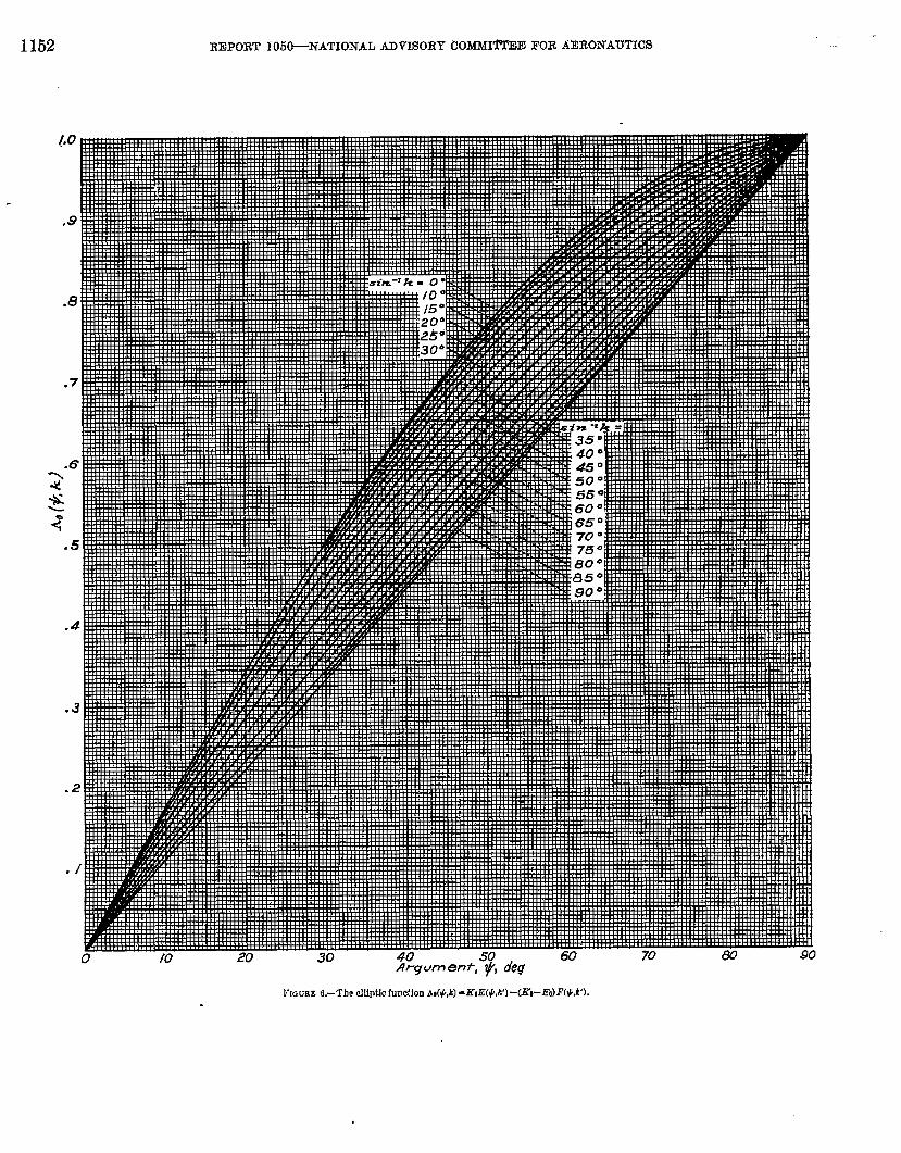
The functions Koi lZ and AOare tabulated in reference 11 ~or” .may -be computed from the tabks of reference 12. ~ plotof &is given in figure 6.
Value at the side edge,—~t the tip, y ia equal tos and thefirst term in equation (15) vanishes. In the second term, #becomes r/2 and 12 (*J’) and E (t,k’) reduce to the completeintegrtds l?’=~(k’) and Z?=K(A’), respectively. Then,since, by Legendre’s relation,
K’E–K’K+KE;= 7r/2—
--
b reduces to 1. The induced velocity correction is seen tobe exactly equal to ‘?& bringing the lift to zero at thewing tip.
Drop in lift across tip Mach Iine,-An interesting effectshows itself at the other limit.of the tip region, that is, at theMach be from the tip of the leading edge. Along this l~!OIJY the influence of the leading-edge pressure is felt, so that
{ The Quantity .Ki Sscalled i% in refaecce lL
. .
1152 REPORT I05&NATIONAL ADVISOR?”COMMl~E FOR AERONAUTICS
Argum en~, ~, deg
kt,;UEE 6.–Th? duPtiC function Ao(+,k)-KtE(##)-(KPEo)F(W).

FORMULASFOR THE SCPEESONIC LOADIN-GOF FLAT SWEPT-BACKWINGS WITH IJZAIXXGEDGES BEHJXO MACHLJS~S 1153-.. —
ao=m. Then k=O, ii’= 1, K=T/2, E($,k’) reduces to
$8or, since along the tip Jlach line .6(s-Y) =r—x~
.&&*=—uQlm&3
~“2(l+m)(mx-psj
This result indicates a finite drop in pressure across theMach line from the tip, an effect -irhichis associated -iviththecancellation of inEnite preemre at the leadirg e~meancl con-sequently does not appear as long M the leacLingedge isaheaclof the Mach lines. The ratio of the clrop k lift QCmSthe tip lfach line to the uncorrected Liftmm b&mitten
M* ~(l+a)(m+a).?i~—=–1 2m(l+m)
fi. ratio is plotted et (z}m in flgu.re i and shows thepercentage loss of lift at tho tip to be ~ery large. In fact,for any but the lowest-aspect-ratio vcingg. the lift remainingin that region is almost negligible. This effect, ~rhichshouIclbe of considerable practical interest, tins tit indicated inthe resdts of reference 13 for the Iimiting case of m=0.
. .{ CL/m &
FIGCBE7.—Pemeut drop fn Ifft across Sach line from tip.
SWEPT-BACK WING WITH SUBSONIC TRAILING EDGE
The. tip-effect correction just derived applies equally to-wings with supersonic or subsonic trai& edges. The effectof a subsonic trail@ edge is calculated separately, ancl isprimarily due to canceling the triangular-wing loading inthe wake region. If, however, the trianggar-w@ loading
?1368?—59—T4
has been modified by the introduction of side edges.,then this ___moditlcatioh must also be taken into account when cancelirgtJpelift behind the hailing idge. h the conicrd-flow method,the various component HOWfields must be canceled individu-ally. The sectiou “immediatelyfollowing rill discuss the can-cellation of the triangrdar-wingload@; cancellation of the tip-induced components of -ielocity rrill be considered under theheading “Secondary Corrections.”
PEIM&Y TRAKESG-EOGE-COEEECTIOXS. .
Procedure for cancetig lift in the wake region ,—Thebasic procedure is again to consider the load to be canceledto be buiIt up by the superposition of uniformly loaded .sectors, bounded on one side ,(see Q S) by the rays a, andon the other by the traiIiqg edge”of the wirg. It is con- .~enieqt at this point to introduce the parameter
m,=19X cot (angle of sweep of tra~~ eclge)
/
L\+
,
-1 0 a -m: f.Ca
FIOCBE 8.—OblIqne constrmt-Uft eIement (sfMe@ for mncelhulcm of lfft at mbsonfc_ e@% end fnduced reklrr discribur[on.
.-
The boundary conditions to be satisfied by the u compo-nent of the elementary canceling ~elocity fielcl are indicatedfor the right span in figure 8; each field must ha~e constantvelocity u=-irhena St. <m~ and zero streamwise m40city overthe w-ake region, —1 <t.<a. The concomitant verticalvelocity must be zwo on the wing surface. However, whena is small, the region —1 <t.<a will include a portion of theleft-hand wing panel Since in th~ region the u component”of velocity has already been specfied, the Tertictd -m.locity

1154 REPORT 1050--NATIONAL ADVISORYCOMMHTEEFOR AERONAUTICS
will not, in general, be zero. Nor is it possible to modifythe field to satkfy the boundary condition on the far wing,since the area involved is not conical with respect to the apexof the field.
The error involved in the foregoing procedure is minimizedby the use of a symmetrical flow field to cancel the initialload UOat a=O, where a single conical field can be made tosatisfy the boundary conditions exactly on both wing panels.This flow fieM (see fig. 9) would have its origin at the apexCO,Oof the trailing edge, and the constant-load region wouIdextend over the entire wake region. Between the trailingedge of the wing and the Mach lines from ~,0 the inducedciownwaeh would be ze~~in the plane of the wing, while thepressure would vary as required tQ satisfy the fundamentalflow equations.
In figure 9, a typica~ curve of u~ is shown, from which itcan be seen that the load to be canceled is very nearlyconstant over a considers.ble fraction of the wake region.Cancellation of the velocity UOby the sjmmetrical field willconsequently leave onIy a smalI variation in u to be canceledby the obLique fields described earlier in the section. Theresulting violation of the flat-plate condition maybe expectedto be small,h and will take pla.ce ody over a small regionnear the tip of the trailing edge.
I.
u
%---.,~ %
-1 -mt o mt 1t.
FIGuRE iL—SymmetrImd flekl for cancalk+tlon of w at subsonfc. tralllng edge...—.
I Cakwlstiona made tG oheck tbls sbdement have shown the induced downwmh angles tGbe less than 0.6 permnt of the angle of attack, even fn the mott nnfsvomble oircumWonces.
Symmetrical solution.—l?or tho symmetrical solution wcdefine the conical variable
&=& ~ (I ij—
which is zero along the centerline of the wing and equals + m~at either trailing edge. Then the boundary conditions to bcsatisfied in the xy plane may be summmizcd as follows:
—ml Sfos+ml ‘u= *UO
?nj<\&l<l W=o
The required solution is given in referenco 14. The u com-ponent in the zy plane is
k% F(~, 1-)‘. ‘. K’(m,)
where h“(m J is the complet.e elliptic integral of the first kind
of modulus ~~z and ~(~, ~) is the correspondingincomple@ integral of argument
r
l–t#~=sin-l —1 —nllz
The form of the induced velocity on the wing (SCCfig. 9) isvery similar to the inverse cosine curves of the tip schtions.
On the wing, d is real and the symbols r. p. may be ornittcd.The velocity induced on the upper surface by cancellation ofw behind the trailing edge is therefore
(Au),= –a F(4, ~~ (20)
Oblique solutions for the wake region.—The symbolt.wW be used as before to indicate a ray of the flow fieldwith apax at X=,ya,the point of intersection of the ray a withthe wing bo?mdary-in this case the trailing edge. Alongthe trailing edge,
V==; (x=–co)
Since a=fl (y.JqJ, we may solve for r. and V=as functionsof a and the constants mI and CO:
x~= :~-a (21)
.
I?v=== -- (22)
Then “~a=PY(~t —a.)—mlcoa
z(ml—a)—mlco,- (23]
The boundary conditions t.obe satisfied by t.hoelementary.solution iwe (for a>O)
a<t=<m, %= &ua
ml<ta<+l I&=o .J
–l<&<(z U=o

FORMULASFOR THE SUPERSOhTC LOADINGOF FLAT SWEPWBACKm-rNGs WITH LEABING EDGES BE-&IXDmum LIXES 1155
The solution satisfying these conditions may be obtainedfrom the tip solutions by an oblique transformation. (Seereference 4.) In the xy plane, the resuhing expression forthe u component is . .
(1 –a)(tti-m,)–(m,–a)(l–tJT.P.&: Cos-= . (1 –m,)(t=–a)
Then the velocity- induced a-t any poi& z,y on the uppersurface of the wing by the ca.nceIIation of the infinit.esimdincrement of perturbation velocity u. orer the sector boundedby the ray a and the traibg edge is
d~u~ da = (Au)==,= cos-’
(1–a.) (ta’–mJ–(mt–a) (1 –+)(1 – m,) (t=–a)
Correction ofmine the lift etwing, it is fitcanceling sector
(24)
loading nesr the trailing edge.—To deter-any point x,y near the traiLing edge of thenecessary to determine the most rearward~ that w-ill influence that point. Setting -t.
(equation (23)) equal to 1, we sol~e for
z—/9y-coao=mt
x—fly-mtco(25)
Then the total correction to the triangular--wing velocity UAobtained as a resdt of cancehig that ~elocity behind thetrail@ edge is—
@w)T.E. (z, Y)=(Au)o+J~’”~ da
The integral in the foregoing expression has been evaluatedin terms of an incomplete elliptic integral of the third kind,which may be computed -withthe aid of the tables of refer-ences 11 and 15. Because it fl be ne.cessmyto detinesevardnew functions it was thought better to present the results inan appendix (appendix B). For practiod use, graphicrd ornumerical integration may be preferred, in which case aconvenient, form is obtained by rewriting u= as (du@a) da,or du& in equation (24). Thus equation (26a) becomes
(Au)~-E.(z, y)=(Au]o–
1J.
u~(a”) (I –a) (ta–nz,)-(m,–(z) (1‘~.r) ~uA (5i(3~— COS–LT u“ (1 –m,) (t=–a)
where t=and UA must be evaluated for selected values of abetween zero and %. The irdegrsnd, of comae, goes to zeroat ~.&(aO).At points tdong the leading edge (ii cases in whichthe leading edge extends into the zone of influence of thetrailing edge), the integral takes on a somewhat simpler form,tith the result that the entire tmding-edge correction atsuch points can be -written
(Auh~d, in the ]tIStwhere the first term inside “the braces is —.Uoterm. ‘
‘=J%2F7SECOX~ARY COREEOTIOSS
The term “seconcky corrections” is used here to designatethe effect of camcehhgthe lift introduced outside the bound-aries of the fig hi the process of canceling the original tri-sngular-~ loading beyond the tips and behind the trailingedge. As previously mentioned, cancellation of Iift at thetip introduces new (negative) components of Iift to be camceled at the trding edgk. The original cancellation of liftbehind the trading edge, on the other hand, miIIintroduce=negative incrementedpressuresoutboard of the tip and, undercertain circumstances (see &s. 1 (a) and (b)), ahead of theleading edge. The distribution of lift. to be canceled in eachcase ia no longer part of a single conictd field, but is composedof an infinite number of superposed conical Iields originatingat various points along the trailing edge or tip. In order tocanceI these pressurw accurately, it would be necessary toset up, for each of the orighd canceling elements, sn in.dnityof positively loaded eleumnts at the opposite boundary.Thus, each secondary correction vrouId require a doubleintegration for each point, and would obvioudy be quitetedious. The procedure is described ii det-ad in references7 and 8. The more recent work of M3rels (reference 5) offersan alternati~e method which, whileno less tedious at the com-putational state, is somewhat easier to setup for comput ing.h’evertheleas, t-heexact calculation of the secondtwy correc-tions, and of the succeeding corrections arising as the second-ary corrections are in turn canceIed at the opposite edges,appears feasible only with the aid of high-speed comput~mmachinery.
These corrections may be thought of as a convergingseries, since.in each case (except in the neighborhood of theleading edge) the induced eEect is smder than the canceledMt. Over most of the wing, the secohdary correction ~ ofthe mine order of magnitude as Lhetolerable error. Formuhisfor obtaining a major part of the secondary corrections ctmbegiven rather simply and shcndd stice to give results ofpractical accuracy in problema (Q. 1(c)) not iurol-iing lead-ing-edge corrections. Problems of the type shown in @ure1(b) vzill’be discussed in a later section.
Secondsxy corrections at the trailing edge.—The press&e-differences induced by the tip are in the main due to can-cellation of the irdnite pre~ure at the leading edge- It..should therefore be permissib~e, for the secondary corrections,to app~oximate the tip-correction field by a single cohicalfield from the leading-edge tip. The lift associated with this
-field may then be canceled behind the wing (see fig. 10) by aaingle iniinity of superposedfklds, as was the original triangu-lar-wing loading. If the values of (Au) tin calculated forpoints x,,y, along the tiding edge are assumed to apply allalong the corresponding rays t~(z~,yJ from the tip, then the
—
.-. _
. —

1156 REPORT 1050-NATIONAL ADVISORYCOMMITTEEFOR AERONAUTICS
kki(.IIE10,-13kctchfor fipplvxlnlate mncellatlon of eyj~m”s I[ft lfii~u~ b~h[ndtire )radhw edge by the tlp wrreetIon.
lifting pressurewill be extictl~canceled along the t,railingedgeanti the remaining variation of pressure in the wake will havevery little effect on the flow over the wing.
The cancellation fields are of the previously used ohliquetype, with a replaced by
~M =f@b-s)
J- ““
(27)
trL
IA:[.[ht?part.iwdarpoint at which the line t~= – 1 intersects
t.lw t rdiug edge be dosiguatecl by Z*,V* and other symbolsr: fcrring to that point be similarly staked. Then thevelocity induced at tiny point X,Von the wing by removal of(Au),,P along the trtii.hn.gedge will ba (from equation (24))
—Au* ~os., 2(t*–mJ-on’+1)(1 –t*)_n- (l–mt)(t”+l)
1-\
‘tni@OtflOJd(Au)liP ~os-, (l–t~)(tb–m,)–(~, –t~)(l–t,)dt~u. -~ dt~ “(1 –m,)(f,–tm)
(28}
whwc Au.* is given by equtition (17), t*and t~are cUlcul~tedby
p=B(H*)X—X*
(29)
and~,=l%y-yb)
x— Xb(30)
respectively, rmd Zo,y. is Lhc point. of inhvsecl iou of llNI 1 [tichforeconi from x, y with th(’ trtiiling edge.
The dwivativc # (Au) ,~Pwould htiw to lw dclrrmindm
numerically or graphically from a plol of the cnlmdalw~values of {Au) ~tPagainst. t~. Iu order h tivoid this proccdurc,it is preferable to N?write expwssicm (28) m
—Au* ~os_, 2&-?nJ –(m,+l) (1–fqT (1–??z,)(t.*+1) 7
1
J
(Au) t ;P (JO,Ftj (1 –tm) (fb–~,)–(???,-t~) (1 ‘fb) ~(AIL),t,— (’0s- )T Au* (l–?nl)(f,–tm)
(31)
in which~b=fw-s)
Z—xb(33)
XOis the Vah? Of ~b Whkh makes tb= — 1, fIIM] (~’U)yT.E, kI
calculated for x=xh, y=s by cquat.ion (26b).
.- NUMERICAL EXAMPLE
Before proceeding to consider the problem of int.crmtkmbetween the leading and tr@ing cdgmj whkh introducessome radically clitTwentCffcctsj the results so far obthinwlwill be illustrated by u numerical example, TIN lortdi]]gover an untapercd wing, with P cob A= 0.6 WN1rcduccdaspect ratio f?xl= 1.92, has beeu calculated at four spfinwisestrdions: 25-, 50-, 75-, and 95-percenL scmkpn n. The wingplan form and section lift.distributions are SLOWUiu llgurc 11.

FOR
.
MULASFOR TBX SUPERSONIC LOADIN”GOF FIAT SWFWJ!-BACKWINGS WITH LE.ADINQEDGES BEBXND.MACHLJXES6
.5
4
21s3?I.
2 — — — — —
Find
, I
(d
o6
5 \
4
\
3
2.%ra[loading----
$:-w
I
3 I I I 1I I t I I I~sf’f%<--? No A
I t I I I I I I 1 1 b 1 \ 1
L ‘% \
. J
/ ! 4
\ 5
-r\
1 .
-2
(c) (d)
-30 20 40 60
D.kfan% from Iedhg e%ge~~”mm 40 60 80 m
-1157 __
. . . __=---+.-
..
. .-. ..-...-
.,
.
,
.-,-
(a) SectIon A-A ria-O.25 (b) Sedfon B-B #/c-O.91 (c) s* c-c q/a-o.m (d) Se&on D-D YIs-O.S6FIOKEE U.—bad dfskfbuffons calcrdated for foor Wn?emwfsesectiom ofanuntamedwfu m=O.6;8A-IJQ

1158 REPORT 105O--+JATIONALADVISORYCOMMITTEEFOR AERONAUTICS
The results of the calculations are presented in the form ofvalues of P(Ap/ga) (equation (5)).
The various components of lift are presented separately asca.lmdated. In figures 11 (a) and (b), the ,discontinuities inslopo show the eflect of the cancellation of the finite velocityw at the traihg-edge apex. The integrated partt of thetrailing-edge correction (component 2) has zero slope at theMach line. The two outboard sections (figs. 11 (c) and (d))are intersected by the Mach cone from the tip, as indicatedby the finite drop in the load curves. Cancellation of thefinite tip effect at the trailing edge (component 4 in bothfigures) resuhs in a sharp discontinuity in pressure gradientalong the reflected Mach line, at 91-percent chord aty/s=o.75 and ah 78-percent chord when y/8=0.95. Thecancellation of the trdng-edge corrections at the tip, whichaffects only the.last section shown, rwuhs in another breakin the load curve at 49-pmcent chord. Further correctionsenter at the rear of the section as a result of successive can-cellations of the superposed pressures at the tip and trailingedge. TJeir effect has been only estimated.
SwEPT-JIACKIVINGS~lTll INTERACTINGTRAILINGAND LEADINGEDGES
11’hen, as in figure 1 (b), the ~Machcone from the trailing-cdge apex includm a region ahead of the leading edge, thepreviously calculated trailing+dge corrections to u must. becanceled in that region, since they represent a discontinuityin pressure which cannot be supported in the free stream.Thus there must be calculated a leading-edge correction,which is one of the previously deiined,seccmdiirycorrections.However, the location of the disturbed field ahead of thewing causes its influence on the wing to be so much morewidespread than that of the other secondary corrections asto require more carefuI consideration. A new type of flowfield is also required, as discussed in the following paragraphs.
LEADING-EDGE CORRECTIONS
Elementary solution for the region ahead of the leadingedge.—In general, the elementary solution required for thecancellation of prwure in the plane of the wing ahead of theleading edge is one that:
1. Provides constant streamwise velocity over an infinitesector bounded on one side by the leading edge of the wing(extended) and on the other by an arbitrary ray extendingoutward into the stream from some point z~,~bon the Ieadingedge. (See fig. 12.)
2, Induces no vertical velocity, or dowmfash, on the wing.3. Induces no lift except on the w“mgand withb the sector
described in condition 1.At first ghmcc these conditions would appear to be satisfied
by the oblique solutions used at the trailing edge, if properlyoriented with respect to the wing, and the same form of solu-tion might be ~~pecte.dto apply. In reference 4, however, ithas been pointed out that the downwash connected with thelatter solution remains constant over the wing onIy if thewing area does not include the line y= constant extendingdownstream from the apex of the element. In the case ofthe Ieading-edge element this condition @ violated (fig. 12)and a.nadditiond term is needed to bring the downwash tozero throughouttthe area of the wing affected by the element.
r1
A~#1
L9ding e~e
i
Kc
-1R
G
FIGCEE 12–hd[ng.edge element and Induced-rrhelty funetIon.
The solution applicable to this case has bccu given ifi refer-ence 4. The u component of the vdocity in the plane of thewing is as follows:
-where uIJis the constant Streamwiso perturhat,ion l“e]ocityover the elemenL, and fb refers as before ta a“ray from itsapex. The ray bounding the element originates a~ a pointon the hailing edge and has been designsted, from equation(24), as tw When the correction is being made for tho sym-metrical trailing-edge elcnwnt, $=is rcplaccd in cqua(ion (34)by h.
For brevity, thti two parts of the correction function willbe referred to M
(ta–rn) (1 +f,)–(m–fJ (I+Qc(tJ=r. p. cos-~ – (1 +m) (tb–t~ . (35)
and
–2m ~;4
l+f*W.J=r.P” (~+m)~=l (tc–~) (1 +kJ m—tb (36)
The variation with t, of these functions and tho inducedvelocity (equation (34) ) are illustrated in figuro 12.

FORMUL-4SFOR TBE SUPERSONICLOADINGOF FLAT SWIWI%BACKWINGS WITH ~lX-G EDGES BEFENO MACHLINES 1159
leading-edge correction to the loading-The single conicalfield of (A@O will be considered fiat. (See fig. 13.) Thevelocity field to be superposed ahead of the leading edge tocanceI the whcity (Au). induced in the plahe of the @gby the symmetrical solution (equation (20)) can be built up,as shown ii figure 13, of overlapping consttmt-veIocity sec-
.
It.I
,,FIGGBE 13-CanceIIatfon of the premure field Mrodmed ahmd of the IeodIug edge fn the
conrseotmncanga behbdthebngmedge.
tors having one edge along the kding edge of the -w@ andone along the extended ray to $rorn the apex of the trailingedge. The magnitude of the constant velocity on each ek-
ment is * d~ or, from equation (20),
UrodoK’(m,)#(l —foq(t;–m,q (37)
Applying equation (34) to the candation of the sym-me.t.rical-correction velocities (Au) o ahead of the ~m resultsin the fo~owing induced velocity increment at any point(z, y) on the@:
J(A,u)o=; ~ ~1 1 ‘(Au)O [c(tJ+@j] ck, (38)
where Tois that value of tofor which tn= —1, and designatesthe most rem-ward leading-edge &lement cont~~ thepoint x, y within its Mach cone. h terms of x and y,
?n(z+py) .“=(z+f?y)–(l+?n)co (39)
--
‘(AU)O C(tO)&ois not feasible by elementaryInte&ation of ~
me-. For graphical integration it is advisable to rewrite _
‘(AU)” dtoas d(AU)o to avoid the_i@hite va.he of the derivative .&
&t %=1.The second term of the product in equation (38) can be
integrated in closed form as follows:
-sL@@ol?(to)dto=–4rn3/2u.JZ(k)r ““”’--
Z+pw .q#, ~) (40}~ dk mt(l+m)K(?nt) ?nZ-/3y
where
‘=IEXZJ , ~““”and
E(k)=Z(*, k)=E(#, k)m (*, k) (41)
The function Z(#, k) is tabulated in reference 16; a plot of
Sroildy, for each oblique traiIing-edge ekment a (seefig. 15), a canceling field can be built up ahead of the leading ~edge by the superposition of sectors bounded by the leadingedge and by rays t. born the apex z., y. of t-he element a,end having a constsnt velocity of the magnitude
W@. it a (1–cz)(t&T?3,)-(7nt-c2)(l -fJ ~ta
at= .=—: ?&~ Cos-1 (1–--7nJ(a)a)(42)
(horn equation (24)}. If the spbol Au.=. is used todesignate the total leading-edge correction to the u com-ponent of velocity at any petit, then the part due to cancehgthe fieId of a single obIique trailing-edge elemmt a is
dAuL~-ZW=W%%’J+R(’J ‘k
(43)
wherenl(m,-(z)(z+py) —?ntccl(l+?7L)CJ
“’= (m,–a)(z+fly)-m, co(l+m)(44)
is the value of t= for which t k= —1 and the leading-edgecorrection function vanishes.
b(Aw)= ~ sub‘i’hen the expression (equation (42)) for ~ -
mstituted in equation (43), it is again impractical ~o attemptto write a closed @reasion for the integral of the fist term “
a(Au)ue(tJ of the product. The integd of the - second _ .“&=
term is ..—
J1a(Au)aB(Q&=i-=af=
(?n,-a)(l –m)(x+~g)–?n,c,(l +?n)(l-ax~l+m)z (1–m,)(%az-py)
2(+., k.) Z(f/o, kJJK(kU)[=a k=sin y=– = kc sin# (45)
.

1160
I
REPORT 10a50-_NATIONALADTISORY
sin “k
AERONAUTICS..
-. ._. .—.-.
.- —At-gumenf, ~, d6g
Z(+h)FmuRE 14.-The elllptlc functkm —
te+in+
FORMEI.ASFOR THE SUPERSOISTCLOADINGOF FLAT SWEPT-BACKWTXGSWITH.IkADIXG EDGES BE= MACHLm= 11 ~~___
where ‘.
~== pm=a\ (1–?7LJ(I+TJ “
(m,–a) (1+Tj*==shpJ=t)
,
.
FIGLm.EIE-CaneeIIatIon Of the presmre deId Eatmdum?dahmd ofthe Ieridtng edge b~ asb.gle obIique lraflhg-edge demerit.
Then the tohd leading-edge correction to the velocity u atany point x, y is
J‘O:d(f@L. E. da
(+u)L. LY.=(.421do+o da.
(46)
where (AZU)Ois obtained -from equations (38) and (40),
‘(AU}L-’- ~om ~quatiom (43) md (45), ~dda
(1+m)c,–(1 –m) (Z+fly)a~=(l +m)m’co–(1 –m) (x+B#’
(47)
is the value of a at which rdr, y, a) (equation (44)) is equ~to 1.
The last term in equation (46) wilI se~dom be found tocontribute any signitlcant amount to the loading, but- will beneeded in calculating the ler@ng-edge thrust.
-. FUETESR coRIuwrIoxs
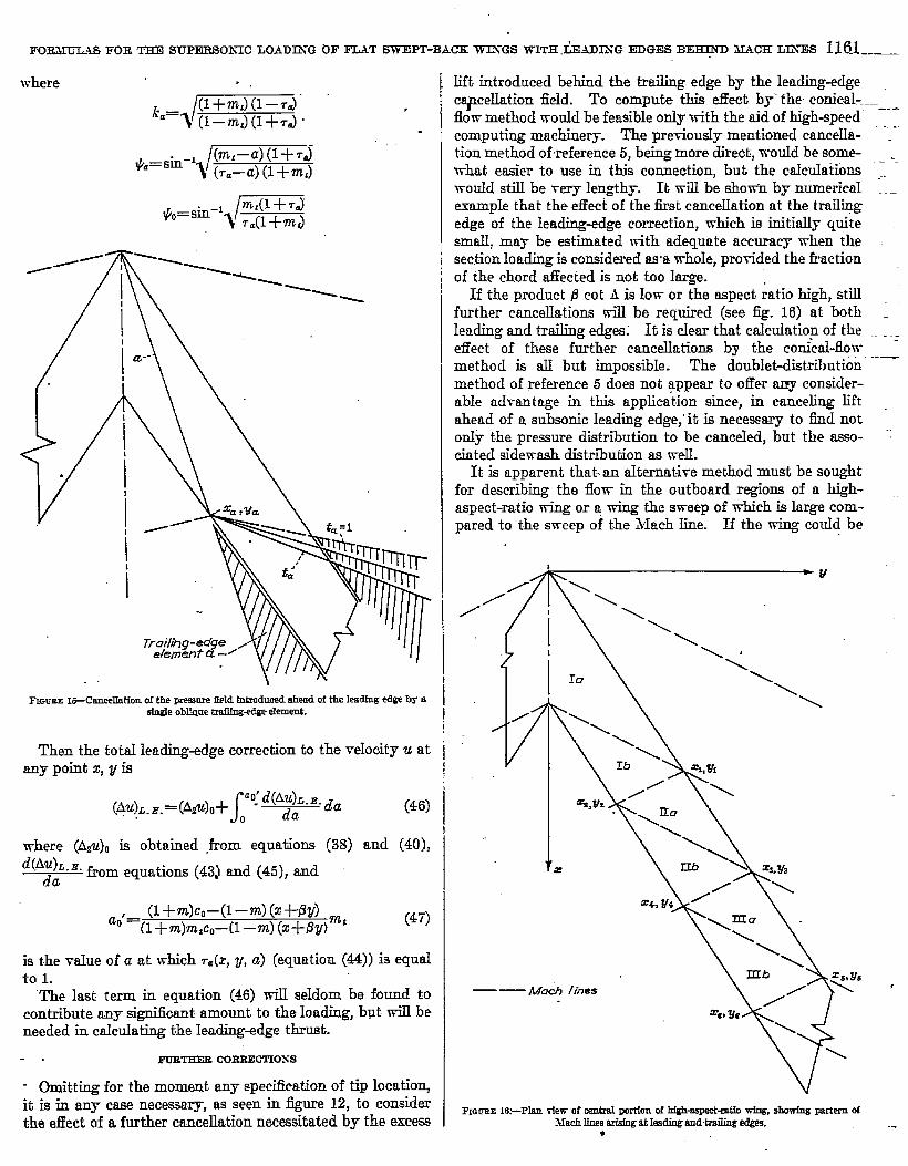
- Omitting for the moment any specification of tip locatio~it is in any case necessary, as seen in iigure 12, to considerthe effect of a further cancellation necessitated by the excess
Iift introduced bebind the traiLing edge by the leading-edgec~celIation field. To mmpute this ef%ct by’ the conieql -----flow method wouId be feasible ordy vrith the aid of high-speed ‘--computing machinery. The pretioudy mentioned cancella- “-“”tion method of reference 5, being more direct, would be some- ._what easier to use in this connection, but the calculations ~.would stilI be mry len@hy. It will be sho~ by numericalem.mple that the effect of the first cancellation at the trail~edge of the leadhg-edge correction, which is initially quitesmall, may be estimated with adequate accuracy when thesection loading is considered asa whole, protided the fractionof the chord affected is not. too large.
If the product B cot A is low or the aspect ratio high, stillfurther caucella.tions rrill be required (see fig. 16) at bothledng and trailing edges; It is clear that ctdctiatiop of the ~.,effect of these further cancellations by the conical-flowmethod is all but impossible. The doublet-distribution ‘-—method of reference 5 does not appear to offer any consider-able ad~ant age in this application since, in canceling liftahead of a subsonic leadiig edge,’ it is necessary to find noton.1~ the pressure distribution to be cancekd, but the asso- “:ciated sidemsh distribution as well.
It ia apparent that--an akmat-i~e method must be soughtfor describing the flom in the outboard regions of a high-aspect-ratio wing or a wing the sweep of which is large com-pared to the sweep of the Mach line. H tho wing could be
FIGUEE 16.LPfan tier of central Portton of hig&as~+a$fo wfng, showing meim dMm?hlines arfsfngat IssdiugandtmiIing @&s.
●
.-

1162 REPORT 105~NATIONAL ADVISORI”CO.W1fiE FOR AERONAUTICS
extended incIefiniteIy,it is known that the flow must even-tually approach the twodimensional subsonic flow, in accord-ance with simple sweep theory. The question then arises,can the flow at a distance of the order of a semispan timthe apw of the swep&back wing be related to the two-dimensional asymptotic flow? While the flow field appearato be too complex to obtain an answer to this question onanalytical grounds, numerical values, presented in thefollowing par~graph, suggest a practical approach.
NUMEIUCAL K4ESULTS (WITHOUT TIP EFFECT)
Load distributions have been calculated by the conical-ffow method for three combinations of taper, sweep, andMach number as follows:
Untapwad 2YPE!2m= 0.2 0.4 0.4
. mi= 0.2 0.4 0.6
These vahws of m and m, represent, b.v virtue of the Prandtl-G1auert transfomnation,‘a ~ariety of-sweep angIes at hfachnumbers between 1 and 2; as for example, 0.2 would be thevalue of m for a wing with 63° sweep of the leading edge ata Mach number of 1.075, or 75° sweep at a .Mach number of
Final loading -.>’
Leoding-edge con-ecfion - Y\
v
Oblique troiling-edge correc?im -
Symme fric fraifing-edge comecffon - J
(a)
20 40 60 80 100Disfance from leading edge, percenf cho~d
(a]%tion A-A f3u&0-O.807
1.25. %dar]y, ?n=O.4 would ccrreepcmd to 45° of SWCCP
at ill= 1.08, 60° at M= 1.22, or 76° at M= 1.80. Thetrailing-edge sweep anglw at these latter hfach numbers,if “m,=O.6, are 34013’, 49°, and 68°, respectidy,
Figure 17 presents the lift distributions at two stationsof the tapered wing. Each component is plotted independ-ently in order to show the magnitudes at the Ieading edge.Section A-A contains the intersection of the trailing-edgeMach line with the Ieading edge, sc that the VRIUOof tholeading-edge correction is zero at the leading edge of thissection. At points farther back along tho leading edge, asat &IlCo=0.8, the correction ‘is minus infinity.” However, i& ,is seen to increase ta a small positivo value within a fractiouof the chord length at this station.
At both stations it is necessary to estimate the effect ofcancellation of the leading-edge correction at the trailingedge tQsa@sfy the Kut ta condition. Cancellation would becarri@ out by means of oblique elemente of the type usedpreviously (equation (24)) in canceling lift at the trailingedge. The pressure to be ekmceled is initially (i. c., rd.%vz (%!. 16)) Zew Then the lift induced on the wingby this cancellation may be presumed to have the samegened shape as the oblique traiIing-edge correction of figure
--- Con-em% forKu+ fa cond!t!on~estimo ted]
--- Triongwfor - winq loading
,Final loading-~’
.
●
L coding-edqe correcfiim -w, \\ 1—--- _ ---+
Oblique trailing-edge ccrrecfion -
Symmefric f~aitinq-edge correction - ~
(b]W.ction B-B ISJ&C.SOO
FmuRE 17.—I.@ddfetribuths eaJeulated by the oonicd-flows method fw two strearnwlae seetfous of e tapered swept-back wing; m-O.4; ?ni.0,6,.

FORBJITAS FOR THE f31WERS0.NICLOADIXGOF FLAT SWEPT-BACKTVES-G-sWITH LEADIXGEDGES BEHISD MACHLINES 1:63 .=——
B’#Find foadinq -~f
Leading-edge correction - Y%
~’
~ymmefric fraiing-edge correc%-r ---
1 I 1 I 120 40 “80 80 100
Disfunce fmm Ieudinq edie. percenf chord
(a) Seetfm A-A BIIjcFO.60i
5
4
3
2
B%
I
c
-I
-2
—-- Cor~ecfion forKuf fa condition
\ (estimo+ed)
\fA~ - Triongulor-winq loading/’
Finulfoodng -~“
Leading-edge correchim -~,\
OMique fraihnq-edqe cwreciion-2’.
Symmefric fraiiing-edge correcfhn --”
r r I 1 [20 40 80 m 1-00 ~.
Disf ante from leading edge, percenf chord .
(b)*dIon B-B Pr[a-OJWFICmEE IS.—Lond dfstribntfons c.ahdated by the aInk8LEowK zm?thd for two streemwfse sm!thns of m mrknpered Z m-O.L .
11, fsdhg aIong a mowed inverse cosine curve from thedue of the error at the trailing edge to ZWO, w-M zerosIope, at the boundary of the region afEected. Vilth tbieboundary (the llach line from the point x2,y2), it is possibleto draw a. satisfactory estimate (dotted curve) of the correc-tion needixl to brirg the pressure once more to zero at thetrailing edge.
The untapered wing -with the same sweep (m=O.4) rehit.iveto the Xheh lines is show in iigure 18, with the load dis-tributions cslcukted at the same stations.
Four section lift distributions are pre;ented (fig. 19] for
?n=o.% Ak ~=0.15 only the rear 60 percent is influencedco
by the subsonic trailing edge. The reflection of this infhenceat- the leadiug edge alters the pressure over the rear 40 per-cent of the sectiom At section B-B, the leading- andtrailing-edge interaction afEecta the entire section. A furtherreflection of this effect at the trailing edge must be estimated.
At section C!-C the iufhmnce of cancellation of the leading-edge correction at the trail@g edge extends over the -ivholeof the chord and any estimate of its magnitude Todd beneceasariIy arbitrary. AIao, B ~cond pair of reflectionsmust be taken into account. The final pressure dktributionhas therefore been dravrn as a band within which the true
curve may be shown to lie. Its height is the error introducedat the trailing edge by the firstt leading-edge correction,except very near the leading edge,.where an infinite negative “-correction is ?mowu to be introduced by the second lea&n& ‘“-edge correction. The mlculat,ionawere also carried out for .-~flyJ%=O.45. The margin of nnoertainty was fonnd not tohave increased by any appreciable arnonnt. (See~. 19 (d).)
APPtXCATiOh- OF TiVO-DIME&IOh”AL FORMULAS TO Cbl,CULATION OFLOAD DISTRtB~ON
Correlation of two-dimensional and swept-back-wingloadings.-It is apparent. fiwm the cdcdated resuks that,,whenever the plan form and the hlach nnniber are such thatthe trahg-edge Nkh liue intersects the leading edge, theload distribution behind the Xkh lines from the point ofintersection resembles in shape the theoretical load distribu-tion over an itinitely long fiat plate in incompnwible flow.However, as the results have been plotted, the quantitativeagreement is not good, particulady in the ease of the taperedwing. On the other hand, if the load distributions in - –cross sections normal to the stream me examined, a nearproportiondit-y of the curves is observed. In order to ‘--determine the fa:tor of proportiomdity, it is only nec~aryto find the ratio of the strengths of the singularities at the ___
●

,
1164 REPORT 1050--NATIONAL ADVISORTCOMMITTEEFOR ~RO”NktTTICS
,/
/1\,
‘-Oblique traifing-edge
correc fion
Symmeh-ic h-oiling-ed~. ” ““
ccv-t-ecfion ---~”E] I I I I I
20 40 ,=.60 60 /003fonce from Ieoding edge> ~enf chord
. ..-
-. .
— — — Correctimfw Kuffacmdifian(estihmlec#
.5
2
Ap
%jzl
G
.=f
\
\\ r - Trtorqular-wing 100ding\;\
Symme +ric froiling-edge, .a-correcfion -----”
~) 1 1 I 1 !20 & : 60 80 100
Disfonce from” leading “edge,percent chord L
(a) SeotfonA-A d9/@=O.16 “
,2
PAp
~“1
6
-1
*.--Tr;ong@r- wing 1000’ing
F“Leading-edge corm iion --
ObJique +~iling-edge correction-.
b) 1 I 1 I t20 40 60 80 /00
Llkfance from” leading edge, percen f chord
\
/
\ ~ -Trianguior - wing 100ding\\!
.Symmetric froifing-eo’ge,..’
d)cor~fj~----k”
/ 1 I I 1
20I
. .40 60 80 /00=.~tonce from Ieocfingedge, percen t“”chod
(b) Eect[on B-B j7uk3-025
(c) %tfon C-O pJk4=0.S5
(d) Seetion D-D pr/[email protected]
FICNJRE19.—L6addistributions calmfatod by the oonicsl-fiows method for four s&mwfw sect!ons of an tmlaprrod WIOXm-0,2,

FORMUZASFOE= srmasox~c LOADIXGOF FLAT SWEW-BACJCWJ3-C3SWTCHIJHDn-G EDGES B-m MACHm= 1165
kwding edge. men an approximate expression for thelorK@ on the outer portions of a high-aspect-ratio W@cau be obtained by adj~tiug the two-dimensional loadingby that factor.
Both the swept-back-wing and the subsonic t vro-dimen-sional loadingg approach infinity as the reciprocal of thesquare root of the distance to the leadi~~ edge. In sectionsnormtd to the stream, the distunce from any point. x,y to the
leading edge may be -written~ (me–fly). The due at, the
baling edge of the coefficient of (zh.c-~y) ‘~fa w-illbe referredto as the stren#h of the leadi~c-edge singularity.
The subsonic two-dimensional perturbation veloc.ity hasthe form ,— . .
(48)
where q is the distance to the leadi~~ edge; expressed as afraction of the chord. and B is a constant. If the section ofthe swept-back wi~~ is taken perpendicuhw to the stream(’r constant), the chord le@h is
; [Jnz-?nt(x-c,)] (49)
Illldmx-fly
~=mr-7nt(r-cJ
.Substit utiot.1 for q in equation (48) gives
(51)
.
Then the strength of the leading-edge sin=gularityin u is
‘IIe letding-edge singukwity in the loadirg on the a-iiept-back wing is initially @gion I, fig. 16) that in the triangnlar-vring loading. -Introduction of the lead@e&~e correctionsto the load, in region 11, reclnces the strength of the sing&r-ity there througghthe terms R(tJ and I?(LJ. (The in-rersk-cosine function is id-ways finite.) The coefficient of(nu—py)-’f’ in ULis. from equation (6),
(53)
ut the leading edge.From equations (40) ancl (45), decrements to this -coeffi-
cient muy be deri~ed for the portion of the leading edge justbehind the intersection z,,Y, wit-h the tid&eclge 31achline, as foIIovrs:
(54)
and, for each value cf a.from Oto that value ao’ which mrtkes7=eqnd to one, ._
[
_ z(#=,kJ— Z(#o,kJl’1+~ jja& $= 1‘ltl —a k=s~ & (55)
where To(equation (39)) and r= (equation (44)) reduce to :..
?nX~o=—
x—co :.
and(m,-a)mx-m,coa
‘a= (L’1,-a)r-m,co .—.— -.—.. L-and the arguments and moduli of the elliptic integralsfoLIovras for equations (40) and (45). .
’116 coefficient. of (mc—f?y)‘~~ at, the Ienc& edge is, -“’””therefore, in region II, figure 16,
-withao’ redticing to
Equating the two coefficients, expressions (56)gives for any one section
.
—.
1 ,1?= [~A+(@O+~o”O ~c daI m7—7nJx—cJ
For convenience, a nondimensiomd coefficient
1@)+-
l“aq~ [‘CL+(AQO+
J‘O’$# da
o 1
is clefined, so thatCT(z)~Eo
13=1’Ct >,mx_mt(z_cJ
(56)
.-
(57)
and (52), -
(58)
(59)
.—-.._
By substituting for B in equation (51), the loading on the ‘-”-outer portions of a s-wept-back W@ is obtained as
.,
Numerical results.-The closeness with vdich the fore-going procedure predicts the theoretical Ioading over svrept-back mings is indicated by figures 20, 2!1, and 22, where the” --pretiously ca.lculat ed load distributions are compared withthose calculated by equution (60). Even in the case of the ._hi@lF tapered -i-ring, the aggeement is seen to be good.__”.At the most inboarcl section of the m=O.2 w~~ (~. 19 (a]) j=there is, of course, no agreement over that portion, forwardof the 60-percent~hord point, -where the flo-w is essentidl~; .conical. .$t station B-B, howe~er, the agreement is +erygoocl. At sections C–c and D–D, rhere the exact theoretical
.

REPORT 105E-NATIONAL ADVISORYCOMMITTEEFOR AERONAUTICS
‘ld’zz’dfE’--”’’\-\I(8) I 1 1 1 )
u m 40 60 80 100OiStunce from ldi~ @m, percent chord
\“r -- Correc fed fm-
!--Conicol-flowstrefkd
Simplesweep fheory--~“
b) , 1 ,100
Disto%e from f~inq.edp~”~ent %od -
(a) Seetion A-A(b) Section B-B
FIfiuRE W-bad distributions on the tap?rd wing aa mlculetwl by theconical-tires method, eom~ed with the twc-dhensionfd apprcmfnmtion.
loading had not beeu determined, the two-dimensional-typoloading lies within the band prescribed by the ccmicrd-flowcalculations. Since the discrepancy between the correctedtwo-dimensional loading and the exact theoretical distribu-tion is already, at section B-B (fig. 22 (b)), less than the widthof the bands in figures 22 (c) and (d) and must diminish tozero at infinity, it may be supposed that the correctcd two-dimensional curve is at least as satisfactory an approximationto the correct curves at sections C-C and outbotird asat section B-B. lt is probably more satisfactory thtin canbe obtained by a limited application of tho conirxd-flowmethod.
The load distributions derived by simple sweep theoryare included in the last part of each figure to show the mrqyli-tude of the plan-form effect and also, in the case of the un-tapered wings, the curves that the load distributions musL
5r ‘
4 -
~
1
: C2mkaf-fbwsmethal ,~ I~,,
3 - ‘A,/,
\~~
Bg-p
‘,\2 - ~B
I - Corrected fwo- .-” “..%%ciih7ensiwltheory--.’*
~(a) .I I I 1
0. 20 40 60 80 fm ““Distonce fnnn koding edge, percen(_chord
/!g
,.
;-.%mpk sweep fheory
. -Slender-wing Mew-y (reif3’
r-Conicot-flO* m&%Od
Corrected tb+v- ‘“dimens”anoltheq...’”
(?3 ~ , I 140 W’ 80 100
L)istorwefm Ieodingedge, pcent chord
(a) Swtlon A-A(b) Scetlon B-B
FIGCEE 21,–LGad dle.tributkms on the rmta~red w’[ng,rn=O.4, w mlculatedby the mnkd-flows methoi, cmmpared with tbe twodlmensfonal spIH’oxi.matkm.

I?OFMUIASFOB ~ S-SONTC LOADIZSGOF FIL4T SWEPI-B-4CK WINGS WITH LEADINGIEOGESBEHIED MACHLI.XES ~167.. .—
3r
I
\
F -Sknder- wing thewy(reference 3,)
Gi7rrecfedfwo-dimensrnnut
fheory --““fwo -dimenstinol,N”
fheory --~
(2] Region I Reg.bn 11(b)
I f 1 I \ L 1 r 1 I 1
20 40 60 80 ‘ [m” -o m 80Dis%nce fk%oo%g edg~ percenf chord
IOU .-Lli#ancefrom i’eao$nq edgej percenf chord
\
Correcfedfwo -dimensimof, N*
fheory --~
(c)1 1 ! f
20 40 80 80 100“Disfance from feodinq edgg percenf chord
.--Simplesweep
Correcfedfwo-dimensional,. ““
theory ---
. .
(d]1 t , 1
20 40 60 80 rmDisfunce fr~ leading edqq percen f dord
theory
-,.
—
(a) section A-A(b) SaoMonB-B(0) Section C-O(d) Section D-D
FInuEI! ~—-d dktrhrtfons on the untapered wing, m-014 as cakmkted by the mtdsd-fhws methc& compsred w’tt.hths two-dttnenskmal approximation
approach as the distance from the plane of symmetry isincreased. h figures 21 (b) and 22 (b), comparison ia aIsomade mith results of the sJender-wi@ theory of reference 3.
Discussion of the c funotiom-k the calculation of thepressure coefllcient at points toward the rear of most of thesections considered in @ures 20, 21, and .22,it was nec=aryto fmd a(?) for vahws of z greater than % (fig. 16). Inderiving u(z), it was mentioned that expre40n (56] appliedto region II. Ii region III, the strength of the leading-edge
singukrity is tiected by further modi6cations of the flowtaking p~ace in region Ill, so that additional terms in r(ti) _should be considered when x is greater than %. Evaluationof these terms by presently known methods would require,as suggested edier, the aid of h~h-peed computing ma-chinery. However, the successive terms are all initiallyzero and enter with zero slope at xs, zero slope and curvatureat X5,and so on, so that the three-tmn expression for r given ___by equation (59) may be U@ with aatisfacto~ accuracy.—.“
b

1168 REPORT 105&NATIONAL ADVISORYCOMMITTEEFOR .4ERONAUTICS
for some distanm beyond the last value of z for which it isstrictly valid. In practice, the”third term in equation (58)may also be neglected for values of x ody slightly greaterthan .rI,
(’=)”Charts have been prepared (fig, 23) giving ~
ns a‘ function of ~ for several values of th~ ratio m/m,.
This last prwametcr is the ratio of the tangents of the semi-apm angles of the Ieading and trailing edges and is constant
through the Mach number rangevalue of xl is readily determined:
for nny onc wing. Tlw
co
‘l=i=E (G1)
Tlm &rves were cornpu[WI using oqua[ioll (.5uj and arctherefore exac~ only up to Z=xt (shown by a vwtind markon eactiu.me). Cross marks are drawn at ihr points X=Z8to indicate a more practical limit to whirh usc of tlw cwrvcs
ac-XL
co(a) mlmr=l. O .
b
(b) m[mr.O.6’
FIGURE 23.-C3mrW for demrmhlog e, the strength of the lesdlng+dge sIngnlmItY.

FOR~AS FOR TB3!I HJP13RSOAiC LOADIXG OF FL4T SWEPT-BACKWITWSWITH J.JHDESG EOGES BERIND MACHLIKES 1 ~69
..-“0 .4 .8 /.2 f.c$ 2.0
.x -.x
co
.75
.70
’65
.%0
..55
.50
A’i
(r) mfmg=O.S (d) m/mt=O.i
.75
.55
.500 .2 .4 .6 .8
---02.4
.x-Zl .x?-xi
c. co
. (e) m:mpO.O (I-Jm “m.=o-sFIG= Z3-Conthmed.
may be estendec[. (These points are off the scale for m,=O.8and 0.9 in figure 23 (a.).} Tf’hen the tinge are untaperedCm/m,= 1.0), rlsyrl+ptotes
/pa(m) l–m
.— Y\ y=+
derived from sirnple sweep theory, may be dra-rm.The cwrves. for the most part, are regular enough to permit
interpcktiort within intervaIs of 0.2 in m~. Hovre~er. atm ~= 1.0 the lines ckninish to a point on the vertical axis; acurve for m~=O.9 was therefore inserted in the charts forvalues of m}m ~ equal to or greater than 0.5. T1’hen m[m.tisIese than 0.5, m=O.9 represents, if the Ieacling edge extendsbeyond z,,w, such extreme taper that the successive reflectionof the 31ach lines (at z%,X6, . . .) take place vrithin a ~er.~smaUfraction of a chord Iength and no useful curve can bedram. l-o curves are drawn for values of m, smalIer than0.2! because o’f the tip-interference limitation mentioned inthe introduction.
Calculation of tip effect.-The foregoing assumption oftwo-dimensional flow can be extended to give fakly simple
.6.8.—
&) 7nh71t-o.4
.
appr@mat e fokmulas for the tip eflect on a high-aspect-ratio-m-@r. It is a~umed that he velocity distiTbnti& tobe canceIed in the stream outboard of the tip is cylindrical;thut is, is rm extension of the -reIocity distribution calculatedfor the tip section aIong Jines parallel to the leading edge-For this purpose the apprcmimate Ioad distribution “gi-renby equation (60) is used, still further aimplifled by assumingr to remain constant at-its mdue at the Ieading edge of thetip section. (Where the wing is tapering to a point and uis changing very rapidly, the tip region is so small t-hattheentire cahxlation of tip effects could probably be omitted.)
The assumption of constant c results in a failure to cancelexactly the lift along the tip. The assumption of cylindr caflom, while reasonable for the untapered wing (compare ifig21 (a) tith &. 21 (b), for exmup~e)vronId appear to be toodrastic for the tapered ~, where neither the chord northe loading remains constant. However, as has been men-tioned earlier, the major part of the tip effect results fromthe cancellation of the infinite pressure along the leadhgedge, and this part d be accurately calculated. Theeffect of the residual lift. on the rearward portion of the tipsection and in the stream should be smtdl..
—.
.—

1170 REPORT ~NATIONfi ADVISORYCOMMTTEE FOR .4ERoNAwr1cs
The distribution of perturbation velocity at the tip stationy=8, with the simplification of constant a, is, from equation(60), approximately
d ~s–m, (ZC–CJ] CO -”u (xc,s)= ff,vcc
[mz.–m, (z.–cJ] (mz.–ps) ’62)
where ze,~ are the coordinates of a point on the tip and V8is the value of u at the leading edge of the tip section.
This expression may be more conveniently written interms of the parameter
(63)
and the varialie~c OS——
&=+ ..—. (64)
which is che distance of Xc,gfrom the leading edge (see fig.24) expressed as @fraction of the tip chord c,. Since
equation (62) may be written
U*VCXd l–&u (g.,s)=—
6X (1–P&)#c ,(65)
where A is the taper ratio CIICO.If the velocity dishibution u is as&med to i% constant
beyond V=S along lines parallel to the leading edge, it !yaybe. canceled by the superposition of conical flow fields ofwhich the constant-velocity regions have one edge along thetip and the other p-arallelto the leading edge, with apexesdisplaced along the tip by increments in &.- The velocityinduced at a point X,V by each such element would be(equation (11))
_, m+tc+2mt6: Cos t.—?n
where
(66)
(67)
and u. is the veIocit.v on each sector,Fo~owing the pr~cedure used iR deriving equation (14),
the corresponding equation may be written for the pres-sures induced by canceling the cylindrical flow
()Au ‘T% ,jp=
where Zo,s is the intersection of the Mach forecone from X,Vwith the tip,
FIrIcnx 24.-Sketch for dertvatlon of approximate :Ip wredlon to lmdlng at :,r.
If the distances of z,y and ZO,Sback of the leading edgr,measured as fractions of the tip chord, are
and
‘=:(’”-!3it can be shown that
(I+m) (x–xJ=mc, (&–&)
from which equation (68) can bc written (withtution for u(2,,8) from equation (05))
(G9)
(7o)
(71)
Lhosub.Sti-
In integrating equation (72), three cases must be clistin-guished: (1) $<1 (alwa~ true for the unt~pmcd wing},
(2) 1<~< ~ (when the point XIVlies mcm than ~ tip-
chord Iength behind the Ieading edge), Rnd (3) ~> ~

.
FORMULASFOR THE SUTERSOXWLOADIXGOF FLYT SWEPT-BACKWIXGS WITH LEH)IS-G EDGES BE-Z) llACH LIXES 1171...—
(a possible cundition for some points near the traihng edge
of a highly swept- or tapered wing).
ln the fit* (<l)
(aip=ai%J%J’+JiE#’’(*~k)l (73a)
where
and & is the function (equation (16)) plotted in figure 6.
In the second case (1 <:<:)
(73b)
where
and Z is the function (equation (41)) plotted in figure 14.
()In the third case ~~ I
where
(73C)
Along the Mach line from the leading-edge tip all threeequations reduce to the value
Au* — U*
Tz=~[ (74)
. By the procedure just describe~ approximate cancellationof W pressure differences outbcmrd of the tip has beeneffected, but the pressures induced by such cancellationnow tiolate the condition of zero Iift in the wake. Approxi-mate cancellation of the induced press~e difbrenocs in thewake region can be accomplished, as before, by maI@ useof the known value of the tip-induced velocity at the trailingedge of the wing, but assuming the entire error ta originateat the lea&ng edge of the tip. . Equation (31) is directlyapplicable, with Au* given by equation (74) and (Au)tiPby
equation (73). On the trailii edge of an untaperecl wing,$=1 and
(75)
There is no corresponding simpMoation for the tapered wing.Numerical examples, tip eEect.—Equations (73) and (31)
have been used to calculate the tip tiect in two ca~, namely:‘nz=’nz~=0.4, f18=0.94CO; and 7n=0.4, 7n:=0.6, fls=0.86c0. ‘.The tip effect has been cahdatcd for each wing at 13y=0.8c0,where the loading wu. prewioudy calculated (@s. (17b) and(18b)) assuming the wing to extend indefinitely. The tiplocations were seIected so that in each case only one reflection ‘“. ~of the primary tip effeck @ected the s@ion at 13y= 0.8e0.
F~ureh5 shows the rssults of the calculations. The heavydid curve in each case was calculated entirely by thecorrected two-dimensional t.hecrg-th@ is, by equations(60), (73), and (31). As a oheck on the accuracy of the _cylindrical-flow approximation for the flow outboard of thetip. Iocation, the accurate theoretical loac@ was calculated
l?umm ZS.-Loacl clktrilmtfomowr sttenmwke section near tip as dcukted by lwe+llmen-sfenel hrmuks. com~ with mm ecmmte theomtfml ralues. -
.
—
. .--
—
..:.
-.-. —
—.
.
.

1172 REPORT 105fiXAT10NAL ADVISORYCOMMITTEEFOR AERONAUTICS -.
.
3
P
-.
CoFrec12dlmensk
4WW-H-F! 1 , . ,
., 1 i
I
“1-tth-l
-1
-2
-~o 20 40 60 8@ /00
(h) Tarwed wln~ m=0.4: m ,-0.6. Section at 68-O%, or 9Spero?nt s?misparr
FIWCRE‘25-CantInued
for one point within the region”of influence of the tip in eachcase. ‘he procedure employed for the exact caldation wasas foIlows:
The accurate Ioadings with no side-edge effects had alreadybeen caIculated, as has been noted, by the conical-flowmethod. A primary tip correction was cakulat ed for eachcase by equation (15), This correction is the cffect of ctincel-ing the unmodified triangular-wing loading off the tip sta-tion. The remaining pressnre dscwences to be canceledconsisted of those int.roclucedby the leading-edge and trail-ing-edge corrections. These pressures Were computed tJy
means of equations (26) and (46) of the present report. andcanceled b.y the method of reference 5.
The r~uhs arc designated by the circled points on rmhfigure. At the point at, which the seclion cntms the tip l[arhcone in each casej a second circled point. indica tea the acrllra( t!theoretical loading. The vtdue cliflers from ‘Lhut cdcuhlt Mlby the appiosinate formulas only as the two lottdin@ willwu [tip effect~%flcr. ““ ““
It may%e pointed otit in concluding this ‘@ion 011lo@’calculatic@ that, while t.hp formulas have bum dovelopcI(l for”plan foti with streamwise tips, tho procedure rnrty IXJada~ted ~-”obvioti” nieans to raked tips as WC1l. lliiWm;;Ir~in- eveiy Fikk the deviqtio~ in the tip regions-of thti physiwlflow frofi~ie assumed potential flow mus~ bc I.wrnc in mind,
.-. . III-LIFT E.-Gfi*ERAL PROCEDUREFOR CONICAL FJ,OWS
.
The total lift for any Iting is, of course, the inlqywl of Lh(~loa@rg o~erthe wiw area.. Iu gc%cr~l,l!oyw~r, it i+~li~rul(to ohtaiyan analytic expression for thr M b~ ti dirwt” ““””integrati& of t.hc lift distribution. In k conicrd-flow _method, ~a~lvantage may be takeu of [lw simp]ici~y of (hi”componefi-t”fields b~’ integrating thr ]ifL msocintrd with rar~j—one and ~~en combi~iif~ tlw rcsuhs in tlw stimu wuj- m”[ ~u~pressure fiel&
Conical elements of area me mnploywl for the inh’gr’rtlious.These are infinitesimal trianglw bqundw~ by two tidjflcrnL “rays o’f the conical field and the inieroephul’boundary of t1](Iwing plan form. Over each of the infinitmifnol Lrinnglcs thI’velocity u of the conical ficlrl will IN ronst-an L Thus itremains ordy to perform a single integmt iotl, with rwqwd 10the conical vr-rriable of the fiuld, to ob[ aiu tho to~tll 1if[associated “with that field,
GENERALFORMULA FOR THE LfFT INDUCEI} BY A SINGLE TIP ELE31 f2ST
The lift (AL)= inducwl on the }ring hy n single canwliugtip element is obtained first. ~th(JUgh Ih(’ notaLion of 1]11’.solution (equation (11)) used to cancel the triangular-wingloading iii employed, the derivation will hold geumally for auycanceling element bounded on one side by the tip of tt swrp[-back” wing, since no use is made of the fact that llw otlwrboundary of the element paws through the origin of (Iwx,y UXes. - we write
s(AL)a=2P V ‘0 (Au)=~~ (/ta-1
(7G)
where (Au)i (equatiou (1})) is the streamwiw inc.rcmmL ofds
velocity induced by the mnceling field r-tnd~~ dt. (fig. Xl) is
the elemcrit of wing area S for intcgrfttion. Flr simplicity itwilI be specified that the. 31uch cone from the rLprx of lhrelement dots not include the apex of tlw frailing wlgc nor anypart.of the opposite tip. Then (am fig. 26]
*(77)
.@Itmay ba noted Urat, as a rasoft of the raveralbillty IIropcrty (rcfmnea 17),.the furmu.hu
for the llft g!ven herein for swept-back wlnga am cquelly ar@lcahle to the swupk(orwardwfnga having the same plan forma but reversedInIrkdhg.

FORMCTLASFOR THE SrFERSOXIC LOADINGOF FLAT SWEFT-BACK WJXGS WITH LliW)lXG EDGES BIWIXD MACHL12’CES~173
A
Trailingedgej/gy*mt(=.&J ------
ta--l/
FIaUKE M.-Sketch for the deowmhmtm- n of Uft fndueed by aslngk tip element.
Substituting from equations (11) and (77) and integrat~hgby parts, we obtain
(m)==+- l&(zt–2#g((z) (78)
where
g(a.)=--& [J%7%:l (79)
and xt—~=is the distance of the ap~~of the element from thetrailing-edge tip.
GEWMLLL FOBBfULA FOR LIFT lNDU~ BY OBLIQUE TRAYLINGBDGEBLEME’NT
TT3ththe notation of equation (24) for the veIocity field ofan obfique lzaihg+dge element, and on the assumption thatthe Nach lines from the apex of the element do not cross theIeading edge, t-heform@ for the elementary area of integra-tion with apex on the trailing edge (fig. 27) is written
(80)
where s—y= is the spanwise distance from the apex of theekment to the wing tip. Then the lift associated with theelement is
f(AL)a=2p v : :, COS-’(1 –a) (t=–m,)– (mt–a)(l–&) dS
. (i –WLt)(t=-a) ~dk
(81jIntegration of equation (81) gives
-.
(u)a=p T“(s–y=)’ft?: [l/=F-w] ’82)
‘ ds--d~= dt=
-fs=?nt
- FIGCEE Zi.-Skmh for the deteqnhatfon of Uft Ind&d by a traUIng-edge eIement.
WING TITH SUBSONICLEADiNGEDGE
UNCORRECTED LIFT
First, the uncorrected triangular-wing loading (equation(6)) iS tite~ted over the vring plan form. The element ofarea is a @mgle formed by two rays from the leading-edgeapex a and a+da md either (1) the trdi.ng edge of the wingor (2) the wing tip, accor@gly as a is less than or greaterthan a,, the due of a corresponding to the ray through thetip of the trail@ edge. . (See & 2.] In the iirst case thedi&rential of area is
—
‘m’~co~2/9(m/—a)* da .-
and in the secondfis’~, da.
.
so that the tutal uncorrected. lift is -
From the geometry of the wing, the relation
(84)
may be deduced. With this substitution, and the substitu-tion for WA from equation (6), eqnat.ion (83) may be integ-rated to obtain
& 482 @u. m2(m,–aJ2
‘–- .,_.’ [,’(cos-1:;;3:j-~—maiz Va {
(85a)

1174 REPORT 105&NATIONAL ADVISORYCOMMITTEEFORAERoNA~Ics
When m,=ml this reduces to . . _
L,It should be noted, that, for a. given plan form, — variesqciwith llach number. only as %.
WINGWITHSUPl?RSOmCTIMILIKGEDGE(TIPCOJ212ECTIOY)
Proceeding to the calculation of the tip correction to thelift, we integrate the. change in lift (AL). (equation (7S))induced by each element a over the range at Sa <m .l’hequantity’ uA(m) is substituted for u= of the initial canceling~ement and .dUA
~ da for U. for the rem@ing ones. As in
calculating the tip-induced pressure correction, the difficultyis encountered that ~A(?n) is irdlnite, and therefore the t’otallift correction must be written in term of Iimiting values.Following the substitution
(86)
in equation (78), it is convenient. to &fiDe the fuDciion
G(a)=k&g(a)
Then the total induced lift may be written
[fiL=2pv??j2 /%ah +.h(a)(?(a)+ s~ ~ Q(a)da] (87)
a-m,
Integrating by parts results in cancellation of the firstterm ineide the brackets. Since G(a,) is zero, equation (87)reduces to ,
where
[( )(Y(a)== ~+~ g(a)——a—a:
Z@l—a)l/(m’+mJ~ (a+a“$1
is the derivative of G(a).
Equation (88a) has been integrated (appendix C) interms of an incomplete elliptic integral of the third kind.If the necessary tables are not available, it may be prefer-able to integrate numerically.7 In that case it is notcci that
d- sin-l ~& ‘aand UA da is rewritten as
-’4sk-’aEquation (88a) then becomw
In tl@ way infinite values in the iutegrand arc a-roidcd.
WING WITH SUBSONIC TRAILING EDGE
The &pressions (equations (85)) for the uncorrcct.cd.liftapply regardless of whether the trailing edge is subsonic-or ~”supersonic. The formulas for the tip correction may serveas a fit approximation when the trailing edge is subsonicif &e accuracy of a second correction is noL required. Forthat purpose the special value for the untaprrcd wing willbe of interest:
If the wing is untapered the elliptic inl,egralsin cquatiou(88a) (see appendix C) reduce to the first and second kindand.the primary induced lift may bc written in the followingclosed form:
~. .:-.: .1.
where
$=~-’mandk=e‘ ‘-The primary tip correction, however, iBusua~y quite l~ge.
It may therefore be d~able to t~e ~t~ acm~t the sec-ondary correction resulting from its cancellation at the sub-sonic trailing edge. Rather than compute a single secondarycorrection to the lift, as an additional item, it is again foundadvantageous to treat each superposed field individually, thatis, to cancel each conical tip field at the trailing edge andfind the net effect on the lift, then intmgrat e over all thetip elements for a combined primary and secondary tipcorrection.
~Orw referem10formapproximateformulavdld whenm is doss ta one.
(WC]
~p correction with subsonic trailing edge.—For Lhe can-cellation at the trailing e-dgeof a pressure.field originatingat a pobt x., s oh the wing tip, equation (82) is applied,with the parameter a, which defines one boundary of theoblique canceling field, replaced by h,Z=,s. The velocity u=is the gradient
dAuXd”
referring to a r~y from
of the field (equahion (11)) to be ca,ncclcd. The distancehorn the apex of the canceling field to the wing~tip is exprc..s-ible as
z~—z. ?nt&.——/9 na,-ta
—

FORMlIL4S FOR TEE SUPERSONICLOADINGOF FU’J! STVEI?T-BACKTVIXGSWH IJMDING EDGES BIIEIXO MACHLDTES 11’i5 ._
Then the effect on the lift of cancehng the single field from3+ is
r–pv?n?(z,–q?)’ t=(Az&= . ~
dAuX–1(?nt-a)~ z
dAuwhich may be integrated, after substitution for —di$‘
(s9)
to gke
*=~., / ~L–~1 7?2,(1-(2)
If the foregoing reanh is added to the Mt. associatedwith the origimd tip eIement, given by equations (78) and(79), it is found that the latter Iift is exactly canc~ed by the@gebr~c terms ~ the reflm~ed ~t, ~ea~
(AL)a=p Vrnt’u-a$-:::,[J
a U+, k)Q(1+a) EO__ -?nt(l+?nt) m~ Smr 1
(91)
for the lift induced by one tip eknent and its cancellationat the t-raihg edge. It ti generally be found that furthersteps in the cancellation process are unnecessary for engineer-ing accuracy.
For the total tip-induced correction fo the lift, it. is neces-—sary to write as before
[ JedUA
(u),,,= 2p Vm?ps’ Jim –u-A(a)J(a)+ —a+m 1~, da ,J(a)da
where J(a) is
(a–at)’ 1 [d(2(1+~) ‘o_— -
1~A&,k)
a~2a: 7nt-a- ?n’(1+ m’) ‘m~ sln#
h integration by parts reduces equation (92) to
J(AL),,P=–2P V?n?1982~~WA(a)J’(U)da
With
J’(a)== &{[(
mt—”a’):+— –nh—a .
a-a’(’--)llEEzEJk)-2(1+(2) a ?n#-a
E%cE%k)-a [( ret-at—mt )
:+—m~—a +K%K%w%H
(92)
(93)
(94)
II the wing is nntapered, J’(a) becomes indeterminate when _a=m. The limiting value is
%i%%-’)l’o(”+w%+i=%a=)l’”o
Further integration must be performed numerically. Inorder to avoid infinite dues in the integra-nd,note again that.
dud(a)= mu. — sin–~g
da m(95)
so that equation (93) may be revrriti%n
. . . .
Trailing-edge corrections.-In deriving thd trailing-edgecorrections to the total lift, primary” and secondary effects-wilI again be combined. Further corrections wilI be ~omitted.
For the symmetrical wake correction, the element of areais obtained from equation (80) by setting y= equal to zero,and substituting i%for t.. Then the decrement in lift in-duced by the application of the symmetrical canceling ele-ment. at the traiIing edge is, from equation (20),
or
where
(A1~)O —4#f?u, ~_ 1_ =— —m; va [ K,’ (m,)1
. (98)qa
The effect of canceling the pressure field induced by thespmetrimI wake correction at the wing tips k obtainedwith the aid of the previously derived formula (equation(78)) for the lift associated -with a single tip eIement. Thepsrameter defining the boundary of the canceIiug tip ele-rnent is now tOinstead of a, and the veIocity on the canceIingsector is
...-
d‘:t:)o.dtO=K’(m,) &$ (h’—-m~ (99)
The distance from the apex of the mncehg sector to thetrailing edge may be expre=ed as
)11.‘8 (m, to
——— (1 00)

REPORT 105eNATIONAL ADJTSORYCOMMITI’E13FOR AERONAUTICS1176
so that the seconda~correction becomes
effect of the syrmnetxical trailing-dge-.
(101)
or
[
(AJjo 4s2 pull ~ 11
2s/2 ~. (k)–lzo (@ (102)—= —— -.
qa ml Va ‘K{ (m,)– ~~, K{ (m/)
——
Addition of this secondary correction to the primar~effect given in cquatioh (98) results in the sirq#ecorrection
By ~ similar procedure, the effect of canceling one of theoblique trailing-edge fields at the tip is readily obtained andaddeci to the primary effect given by equation (82) to yield
ret—a
— J~&(% k)]~’l+?nt(104)
J—— .-I–mg
J
(1+m,) awitfl Ii= —and t=sin-l
l+m,as the combined
mt (1 +a)
primary aud secondary correction to the lift due to a singleoblique trailing-edge cancellation.
For the total correction to the lift due to cancellation ofthe gradien~ of the triangular-wing Ioading in the wake,equation (104) is integrated graphically m numericallyacross the span as follows:
NumericaI examples to be presented
~’(mt—a)(1—a)—
(105)
will show this com-ponent of the lift to be very small, in general.
WING WITH INTERACTING LEADING ANDTRAILINGEDGES
In computing the load distribution it was feud t~at,when interaction takes place between the flow fields of theleading and bailing edges, the wing plan fo~ .appea~ tocomprise two principal regions separated (see fig. 16) by theMach line arising at the point of intersection xl,yl of thetrailing-edge Mach line and the leading edge, Ahead ofthis line (region 1) the flow is most readily described interms of conical fields. Behind this .lim the flow is morenearly two-dimensional. On this basis, the total lift wilIbe found in two parts, using for region I the conical-flow
expressions for the loading, and for the rcmaimlw of tlwwing the quasi-twodimensioxial approximation.
I LIFT ON INBOARD PORTION OF WING
The’. uncorrected triangulm-~ving ~omiing ~{ill first beintegrated over region I, shown shaded in figurr 28. For
o
““l1
\ ‘1xl
‘FIGrRE Z8.-Intwrd portion (r@gIon1] of hIglwspwt-M 10wing.
this purpose the region is considered in two pnrts, separatedby the ray a~ from the wing apex to tbo point z2,B2. WIUH1
a is less than ag, the element of mea is as before
When a>al, the element of area is
(1+ m)’c$ da219(1—m)~l + a)*
Thus, the uncorrected lift ill the entire shndcd region is
[sLo–2p.~:“ m,a f(1.+m)’
o (mf —a)~UAd(l+
. lK’ m)’(1 + a)~‘Ada 1(106)
.

FORMULASFOR TEE SUPERSONICLOAIXXGOF FIAT S1’Z@lPIT-BACKWINGS ITITH LJ3ADm”GEDGES BEHJXO MACHLINES 1177
or .
with2m m,
h= l+?n+m’—m?nt
When m,=m (untapered wing), the second par.
(107)
(108)
of equation(107] becomes indeterminate: In this case,
The trailing-edgo corrections to the loading are to beintegrated over the ptwt of the shaded region behind thetrailing-edge 31ach Iines. Integration of the symnletaicalwake correction (equation (20)) yiehle
(AL). —16m2cQ2
{ [~ E“’(m,)
- l–~ –—~=13(1 +mt)(l –m)’ Va 1—??%, K{(m,) 1}(110)
For each oblique elernent, the reduction in lift is gi-ien by
(11 1)
(112)
The total lift- in region I is then given by
L()
‘2@ da (113)_LO+~+_ZJo . da~ ~—<a
()The quantity --& ~ ~is plotted against m~in figure 29 for
several values of the ratio m~mf.
LLFT OX OUTER POETIONS OF W12\-G
k order to find the tat-al lift- (=cept for. tip 10WRS)on theremainder of the wing (@. 30), a double integration withrespect to z and y is performed on” equation (60). ~ firstintegration, with respect to y, yields for the indefinite
- integral
(114)
The values of py to be substituted as limits in eqtiation(114) are indicated in figure 30. Along the leading edge,the. right-hand member of equation (114) reduces to zero; ‘“-along the traiIing edge it.becomes
r r(z) ,- -—-—
TCOvmtcO-(mt-m)x -.-——
219
Then the toteJ lift on the outboard region (both winghalves), except for’ tip loses, is
.(11 5)
where
f~=-l!m,co–(m,–m)z
f3= do+m) (%-z) - f6= Wm=a “The indicated integrations may be performed numericallyor graphically, using values of a(z) taken horn the charts ofIlgure 23. /
.TIP-INDUCED00RRECT20X!rOTHEI.lFr
In deriring a tip correction to the lift, the same simpl.i@gassumption of completely @indricaI flow will be adoptedconcerning the pressure field to be ca.neeled as vras used iU .= _.obtaining a tip correction to the loading. A in the precedingsection, a combined primary and seconcla~ tip correctionti be derived. AII further corrections -will be omitted.
lf the notation of equa~on (63) is used the distance fromthe apex ZC,Sof a cancebg element to the @ailing-edge tip isCJI —&J, and the lift induced by the element and its cance~a- . ‘~tion at the trailing edge is, from equation (91),
(AL)e=pVm:tLc ,tmt_m)[,m.o(a-#-A*]ct*(l—fy
(11 6)
where
since the outer boundary of each element now has the dopem—.P
It is seen that only u= and (1–.I%)’ in tie coefEcient ofequation (116) very with the element. For the fit eletient
($-0), tie ~e~ocity UCiS tie ~ti~ V~Ue Of tie ~mrrected “~docity along the tip section given in equation (65), and, forthe other elements, the ditlerentid of that velocity. Then
—

1178 REPORT“1715fiNATIONAL ADVISORYCOMMITTEEFOR “AERONA~ICS
i?
o .2 .4 .6m~
.8 40
FIGUEE!29-Chart for the computation of Ilft In region L
o

FORWUL4S
A\/\\
A X=q
{
/98‘=%i
I
‘%x =ir~
FIOFBE 33.-Boundarfes of outbosrd rezionof MgMwect=atfawin&fok me as ffmfts ofhtegnifon fn eqnatfm (114).
the combined primary and secondary tip correction cm bothwinghalves is -
AL 4mt2ct2u,—=–p (m’-?n) -Xqa [mEJk)-
:*q&J1-,=YJ=,+
S:(’-’’’iw=])”.] (117)
Integration by parts gives, My,
(118a)
H the wing is @tapered, equation (118a) takes on the value.
—AL‘qa
= —P~~~#T a=[2m~(k) + (1—3m)l?O(k)l (118b)
lkcept for the occurrence of u,,ct and h in the coefficients, thetip correction obtained in the foregoing way is a function of”mand m ~ od,i-, independent of the tip location. VaIues of
()~fiu have beenplotted in figure 31 & a form simikwC,C’* ga tip
();a =(@. 29).to t-hechart of —
—
.—
—
FIGmE 31.—Ch8rt for theeorrectfonof the lLftfor tip ef&ct, nsfng two-dfmem.fotiformukks.
APPLICATION OF LIFT FORMULAS
. CASES coMPIJTm
The J&curve slope CL=has been calcdated for two fmdies “’=of uhtapered wings with varying aspect ratios as folIorvs: -
tm-02 m=-O.4
r 1 1. —.-
—
and for two tnpered viings: -
Fi?=i=l-I IL:
I I.34.. H % I
I I I I
It shouId be noted that the untapered-tig cases (except forthe lasli one under m=o.4) represent three wings of fiedgeometry at two diflerent Mach ntmibers such that 13is _-doubled in going bm the fit to the stiond. No calcula-tion was made for m=O.2 to correspond ta the Iast case ““ -

1180-“
REtiItT 105PNATIONAL ADVISORYCOMM.I~E FOR AERONAUTICS
-..,
under m=tl.4 because at the lower Jlach number it was notpossibIe to calculate satisfactory values of a out to the wingtip, The tapered wings were chosen to show, by comparisonwith the first two of the untapered m= 0.4 wings, the effectof taper with the span held constant and, by comparisonwith the second and third untapered m=0.4 wings, theeffect of taper with a given aspect ratio.
SUMMARY OF COMPUTATIONS
With m=O.4 and I%IcO=O.6,the trailing&ige Mach lineEdo riot intersect the leading edge, and the values of CL=were
obtained entirely by means of the conical-flow formulas, MfoIIows: -. :.=
Tapered whg, p.+= 1.6 Untufm?d, L?.4-1.2Component of ltft ‘!%’””
.
flLfQat,* % total pL/@c# % total
, —. --—
Uneorreeted triangular wing. . . . . . .TlpelTect. -–__ . . . ..–-_.._.._ $$ 2Z %: 2% %Symmetrical traflfngdge omre*
tion...- —- . . . .-. —--- -.—-Obliqne traibg-edge correction . . . [%) & 1:; :::: -:: ~
1 I ITotale_____________________ L 72J lW. o L 814 MM,o
flc~m+~gas, pa radon. . . . . . . ..-_. ----- 1.WI 1.ti12 -.
The calculations for the remaining values of&4 are summarized in the following table: ~ .:., -.. .;.. ..._...- ..... . . . . -,_. , .. .. . .-=7,. .=.— 1~ 1
CM8pered wlnge
Componentof Hft Obtained frem m -02T md WIIM –
m-o.4 Tm= .4; mrO.@
i“””” “.
p#-o.8; IYA=d
P.’bo,q
Lfft m htid~kn . . ..- . . . . . . --------
#9A-o.8 ‘Ltl=lz &b+L6 PA-2.4 $A=3.2
Ffg. Zloreqrration (118). . . . . . . ..-- . . . ..- 0.208Lfft on outbcar Wt[on ------------------ Equstlon (115)..- . . . ..–---— --------
a289 2.l!2a
-i% :Ei
z 1% z lx 1.X1Tip Man----------------------------- Fig. 81or WurMon (118). . . . . . . . . . . . . . . -: %’
. 8i9 X598 4.459-.333 -.392 -.416 -:%
1 I 1 I I
‘J
~~~ ~@#m.-.---m-... - . . ..---... -..-_ --.. ---G --------------------.461
ffCL.=PW , per radiarr- . . . .._.-.—er12 1:O&s
.17.
::4 pJa..—
fi~n am”.-- .--— .G - . . ..- . ..-. --------- .77 :s3 Z!m
. —
DISCUSSION OF RESULTS
‘1’he results of the calculations are plotted against thereduced aspect ratio I%Ain @re 32. The curves for theuntapered wings may be seen to be approaching, at theupper end, the value 2mnld= given by simple sweeptheory.
At. the lower end, the curves should approach the origin
along the h? CL=’~ A given by low-aspect-ratio themy
(reference 13). The two points on the m= 0.2 curve for&t<I are not entirely accurate because no account wastaken of the interference between the flow fields from thetips. The points are included, however,. because, with somuch sweep, the wing areas affected me small and the inter-ference effects” should be negligible. The resulting curveappeam consistent with the corresponding curve calculated
/.%.
mFIGURE s2.—VarfatIon of lfft-mrme elow with asp?et ratio.
by the slender-wing theory of reference 3, although a dis-parity in plan form lessensthc significance of the compa risen.
The slender-wing-theory dues are alsoplottwl form =0.4. -_
In that case, however, the assumption of rstremc slendernessis no Ionger justified tmd introduces an Rpprcciable error.(It should be mentioned [hat. the asympototc for the slwdcr-wing-theory curves is below the value giyen .~); si.ulploSWCCPtheory by the factor ~l–mz.)
An e&mate of the accuracy of the lift formulas of t.l}cprescmtreport., compared with results which would t~l{o intoaccount all the successive reflections at the tips and trailingedge, may be made from the following observations:
The values obtained (in the first table) from equatiol~”(96) and”- (103), which combine primary and secondarycorrections, differ from T-aluesobtainable for the prinmrycorrections alone by only 1 percent of the total lift in the caseof the tapered wing, ancl 4 percent of the total lift for thountapered wing. Third-order corrections would bc only afraction of those small corrections ancl would, in turll, hpartly canceled out by a fourth-order correction.
The results in the second table, incorporating the two-dimensional appro.timations, agree within 2 or 3 purccw~with values calculatid entiroly by the conical-flow method.
- IV—DRAG DUE TO LIFT
The drag due to Mt. of a wing with superso~c lcwlingedge is s@ply the lift times the angle of attack, When thuleading q@e is su&cmic, t!le clrag is reduced by a suctionforce due to the upwash around the leading edge. In theLinearized theory this force appears as the limit of theproduct of an infinite velocity across an infinitesimal fmn (uIarea.
The formula for the suction force on a subsonic lendingedge has been derived (see, e. g., Hayes, referenca 18) by

FORMtfIAS FOR THE SUP13RSOXIC LOADING OF l?I&T SWEPT-BACK WINGS WITH LEADING EDGES BEEIND JL4CH LIl@5 11S1 ._
assuming the flow near the leading edge to be essentiallytwo-dimensional and applying the results of two-dimensionalpotential theory. The simple remdt. obtained in thatmanner has been verified for the swept-back wing of finitespan by application of t-hesomewhat diilerent approach ofreference 19.
By the two-dimensional approach, the suction force isfound to be proportional tu the square of the strength ofthe 1eading4ge singtdarity in the. perturbation +eloci@ U.The latter is the quantity discussed earlier in cormictionwith the adjust-meritof the two-dimensional lotiding to theloading on the swept-back wing. Vlth the use of the pr~~ioua terminology it is possible to write for the longitudinalcomponent of the suction force per unit streurmise lengthof leading edge,
(119)
vrheri CA (equatiog (53)) is the value, at the lead@g edge,of the Coefkient of (W —By)‘M in ‘UA.
Then, if the trailing-edge Nlach fine does not intersect theleading edge, t-hethrust is merely
~~a 7
The total drag due to Iift is obtained by subtracting thethrust from the product of the lift and the angle of attack,or, in coefHcient-form,
C%= CYC=-C. (121)
where C= is.the thrust coefficient T/@Y. Thus, in the foregoing case,
““=:[:-+OW’-l “22)Vi’hen a portion of the leading edge is influenced by the
trailing edge, the Ieading-edge singulari~. takes on, for thatportion, the value given by expression (56), which thenreplaces Cd iU equation (119) for the tbst. The tot~thrust is
where
locates the intersection of the tmiling+dge Mach line withthe leading edge. Integrat~hg the first term and reducingso coefficient form gives
so that
In @e 33, ~ times the drag-rise factor & is plotted
against the reduced aspect ratio DA for two combinations ofsweep and lIach number, m= 0.2 and m=o.4, for untaperedwings. Comparison iEmade with a theoretical minimum for _slender wimggin supersonic flight obtained by-R. T. Jonesin an unpublished amdysis. .I.king a method similar to Hayes(reference 18) and assuming the -wingto be narrow comparedwith the Mach cone, Jones has derived a minimym -wave-dragcoefficient
(1 26)
where 4 is the aspect mt.io defined in the streamwise,instead of the spanwise, direction; that is, if 1 (munericalIyequal to Xt) is the over-all length of the wing in the streamdirection,
A.=1’@ (127)
lG——flci’
FmuwiS8.-T%rfstIonofdrawisefsetorwfthwest IMOformtfm~ IF&.
The wave drag is to be added to the vortex drag, which isthe induced drag of subsofic flow, calc~ted from thespan-wise loading. Using the minimum induced drag ob-tained from lifting-line theory gives as the minimum super-sonic drag-rise factor 8
(128)
It may be seen that the drag rise of ~ constant-chordswept-back wings is fairly close to this mmnnum, especiallyht ti lower vidu~ of m for which equation (128) yasderived.
V—SUMlMA13Y OF FORIWUIAS
The formulas for the loading, lift, and drag coefficients aresummarized in the following table, in which the equationsare identified by number.
~Tbls resultha Sh2EbeenpubIfsbed in The Journel d the AemIsuW [email protected] no. 2,Feb.1961,PP.7&8L
—
-.
—
,.
-.
.-
.—
-.
—
-.
—
.

1182 REPORT 1050-NATIoNAL ADVISORY COMMImEE ‘FOR Ai3R0NAmICL3 .
I I
CaseI~
— — Mach Iines ,
I
I
.-
.
1-.
234.5“67
l“.,23.”
4 ---5
6
~.
Equations fo~ u
(6)(6) + (15)”
.“
;.. -
. ..’. ;:,. = ... . .
.= . -“
i.’
(6) ,.(6) + (15)’(6) +(26b)(6) + (15)’+ (26b)(6)+ (15)a+(26b) +(31)(6)+ (15)C+ (26b)+ (32)(6)+ (15)’+ (26b)+ (31)+ (i~
~.j.
. ;.~,...-
,“. .7,
(6j “-(6) +(26b)(60)’(60)’+ (73)”.’’”(60)’+ (73)””’”+ (3i) ~- “““Not evaluated
- -.
(85) +(88)
.
(85)+(96) + (103)+(105)’
(113)’+ (115)’+(118)”6
-..
~,
Equa. No..-
(122)
(122)
. .. ..’.
. .
(125)’
J
c ln evaluating, use fig. 6.bIn evaluating, use fig. 23. .~lU evaluating, use fig. 14.‘.or see fig. 29. —‘or see fig. 31. .-,: .“.— -
-
AMES ~EROXAUTICALLABORATORY,NATIOXAL iiDVISORY COMMITTEEFOR AERONAUTICS,
hiOFFETT FIELD, CALIF., Mar. 1/5,1.960.
.—-
—.

FORMULAS FOR ~“ SUPERSONIC LOADING OF FI&T SWEEC-BACK TWX& WTTE IJ?L4DING EDGES BE- MACH IJXES 1183.—.....
APPENDIX A “
SYMBOLS
vM
BU,o, w”
P
!Z
Ap
:T
0.
c.=
c?.
0= ,:::
6c18s1A
h
:
x, y
% ‘i/U
x~jyb
xc,8
% Yo
% YI
% %
x*, y*
Xt,8
..C+ESEEkL
free-stream wloatyfree-stream 31ach numberWm=iperturbation velocities in stie~wise, croesiatream,
and verticaI directions, r~ectiwlydensity of air
dynamic pressure(. )
; J3v’pressure @iilerence between :upper and lower
surfaces, or Iocal liftangle of attack, radians .liftleading-edge thrust, or component of leading-edge
suction force in flight direction
()Iift coefficient 4@S
dGL( ).
Iift-cur-re slope ~
()drag’”coefEcienk $ . .
—
()t.bhstmeftlcier.it z “.’“:’qs
WISG DIMENSIONS
root chordtip chordsemispanwing areaover-all length in the steamwise directionangle of sweep of the leadi~medgetsper ratio (c,fcJaspect ratio (4#~S’)st.resmwiseaspect ratio (P~&’)
“RECTANGULAR COOBDEVATES -
Cartesian coordinates in the stream direction andacross the stream, in the plane of the wing
coordinates -of apex of coticaI field used to canceIhian&dar-wing loading (Equation (8) at tip,equations (21] and (22] at trailing edge)
coordinates of aprzxof conical held used in second-ary cancellations
coordinates of point on tip; apex of conical fieldused to cancel assumed cylindrical load
coordinates of inte~ection of Mach forecone fromz,y with edge at which correction is being made
coordinates of intersection of tmil.ing~dge Machcone with leading edge (zL given by equation(61))
coordinates of intersection of Mach Iine horn Zl,ylwith traihng edge (Q given by ~uat,ion (112))
coordinates ‘of intersection of tip Mach Iine withtmiling edge
coordinates of intemection of tip and trailing edge
E streanmise distance of x,y back from leading edge,as a fraction of the tip chord (eqmition (69))’
“.% “ distmce of Xo,sbehind leading-edge tip, as a.frao-tion of the tip chord (equation (70))
& distance of xc,a behind Ieading-edge tip, & a frao-tion of the tip chord (equation (64))
—.CONICAL COORDINATES . —
k the follo-iviug, d slopes are measured counterol-e. ____from a line extending downstream from the apex of the wingor of the pertinent cxmcding sector:
..—
‘m
-m~
a
(30
-.
ao’
azag
-la
tb
“L
t=
t*
To
1-=
uA
%Au
u.=
ub
UC
slope of leadihg edge=p ~t ~ .slope of lfac.h ljnes .-
slo~e of @aiEng idge - ““’”dope. of “Macli k&j” [f-: ,.-
skp.s of Xay from tie.ori@”-” - ‘ ‘“-:“’slope of Mach lines -.
=P: , ‘-“—
the -raiueof a corresponding to a primary oancelingelement of which the apex lies on the Mach fore-cone of the point at. which the load is beingc~culated (equation (13) for tip corrections,equation (25) for trailing-edge corrections)
limiting value of a for leading-edge correction~(equation (47))
. .
a(q, y2) (equation (108))a(zl, s)slope of ray from apex of element a Y—Y.
slope of Mach Iines =P= -—-.slope of ra~ from Zh,y&=Py—y&
sIope of Mach lines x—x~slope of ray fkom xc,8FP y—8
.
slope of Mach lines .x—z=slop; of ray from leading-efige tip
slope of Nfaoh lines=~z_Y;8;m1’
slope of ray from z*, fjr*slope of Mach Ikes ’19~
%.&g -due of fa for leading-edge correction(equation (39))
Iimiting value of t= for leading-edge” correction ~(equzdion (44))
COMPOX-EIITS OF STREAiiE PERTUEEATION VELOCITY
basic (uncorrected) perturbation velocity as givenby solution for tiaagular wing (equation (6)for subsonic leading edge)
.-
value of U3 at a=O (equation (7))oorreotion to U4 induced by cancelktion of pressure
differences outside the wing plan formconstant perturbation velocity on sector used in _
cance@g trianguhm-wing loadingconstant perturbation veIocity on sector used in ‘
secondary cancellationconst,wt perturbation velocity on sector used out-
board of tip in cmceIing assumed cy@lrimIfield

1184
(Au,)O
(A,u),
(Au)e
Au*
(’~
(AO}o
dACz-da
u
U*
P
9c
R
r. P.
REPORT 10.50--NATIONAL ADVISORY COMMITTEE FOR AERONAUTICS ,
s~ehid t~~ihg+dge correction to uA (equa-tion (20))
correction induced by canceling (Au). at. leadingedge (equation (W))
correction to uA due to single oblique traihg-edge eIement (equation (24))
value of tip correction to ub at the point x*, y*
AItBITRARY MATHEMATICAL SYMBOIS
value of coefficient of&
in tiAat the lead-
ing edge (equation (63)) “ Idecrement ti CAdue to reflection of (Au), at lead-
ing edge (equation (54))
decrement in CAdue to reffect.ionof (Au)a at leac]-ing edge (equation (55))
Non-dimensional expression for strength of theleading-edge singularity (equation (59))
[“(91value of a at leading-edge tip a
‘aperpa’amekr(%3
function defied by equation (79)inverse-cosine term of leading-edge correction
function (equation (35))radical term of leading-edge
(equation (36))real part
correction function
ELLIPTIC INTEGRALS AND FUNCTIONS
k modulus of elliptic integral, {lcfimxi whwx’ Ilscd(also with subscripts)
k’ complimentary modulus ( ~~)@or# mgument of elliptic integrals, defined whcr(i USC(I
(also with subscripts)F(4, kj incomplete elliptic integral of thu first kind of
modulus k and argument @K, K(k) complete elliptic integral of the first kin~i; thtit is,
E(o, k) incomplete elliptic integral of the srcond kind ofmodulus k and argument @
~, ~(k) Completeelliptic integra~of the second kimi; that is,
()E=E ;,k
KO : ‘K
E. :E
K’ ‘- K(k’)E’. E(k’)z zeta funrtion (equation (41))ho function used in evaluation of elliptic integral of
the third kind, circular case (equation (16))
I L? function used in evaluation of elliptic integral ofthe third kind, circular case (equation (B] 1))
APPENDIX B
EVALUATION OF THE INTEGRAL IN EQUATION (26)
It is fit nccesary to recrdIthat tais a function (equation(23)) of z, y, and a’. After substitution for t=in equation(26), we may integrate by parts to obtain
JUoCOS-I (1‘~) (~a–@-(W-U) (1 –~ dUA (a) “
(1 –7n,) (t.–a)~ da=
o
[
(l+m’)/3y-2?nt(z -cJ_– ‘uo Cos-1(l–?n, )py
(X–py) 4~V–mt(x–cJ ‘– ,- “ “- .
2-&j-m,co x
J
no da.
““1 @l)o @y-czz) J(I –a) (aO–a) (m–a) (m+a) .
The integral term on the right-hand side of equation (Bl)is an Wiptic integral of the third kind which may be eval-uated through the substitution of
d..2m(ao–a) ““a=sn-’ (m+a~ (m–a) “’=-
If the value of w at the lower limit is designated by q, thissubst.itution gives
f
no da.0 (&–ax) IJ(l–a) (aO–a) (m–a) (m+a)= ““
_.,
where ,_~=(m+aJ (m-fly)
27n (f?y-aox) (?33)
or
where

. \
FORMULAS FOR THE SUPERSONIC LOADING OF FLAT SWEPT-BACK WINGS WITH LEADING EDGES BEHJZS~ -MACE LIXES ~185 - . .----
is the nornd form of the elliptic integral of the third kind.It is fit noted that n>O. For this case it can be show-n
that the substitution .
IIz(u,,k, ?t)=cdoC712(,,kq+[
sn (v,k’) C?l(v,k’) co.dn (v, k’) ~ &(~, ‘#)+Q
1@36)
where
@i)
is the amplitude of the elIiptic function v, A is the functiondefined in equation (16), and Q is an angular function of k,pand W.which wilI be discussed later.
If
and dn(~,k~=e
maybe found, so @t equation (B6)
may be rewritten without recourse to the Jacobian elliptic ““~.functions as
Ha(wo, k, n)=-&@, k)+
This expreaeion is to be substituted in equation (B4) andthe result- used in equation @l). h previously mentioned,the functions m and AOare tabulated in reference 1L“and Aais plotted in figure 6. The function Q is given by S
(tabulated in reference 15).
~TIIe symbolsIneqnaicm (BLL)Issbmdard notati fcwthe nom of the Jwmbfan thtnhmctIoUmdis notreIatedtothed- p~ e of the text.
APPENDIX c
INTEGRATION FOR LOSS OF LIFT AT THE TIP OF WING WITH SUBSONIC LEADING EDGE
From equations (88a) and (6) .-
where
(C2)
The terms in G’(a) are of two types; namely, those thatcontain ~~ and those that do not. The former combinewith the radical ~’rd—az in equation (Cl) to form ellipticintegrals of the first-, second, and third kinds. The lattergive rise to terms in equation. (Cl) which are integrable byelementary means. It is convenient, therefore, to considerthe integral in two parts, writing
-where 11 is that part. of the integrtd not requiring ellipticintegrals.Then
s a—i2~1,= .: ~t2mta(mt_a) (:+=) ‘a
,J.m2_a?
1
“J
(m,–a,)z ~os_, m,a,–m’ ___—a;%ng(mtz-?n ?Im ~z—mz m(mt —aJ
mtat—m2
.The remaining terms, involving J- and
are integrated by means of the substitutio~
‘“W’G “k=l=The result is
(C3)
.—
(C4)
1,=1
{[=(R%:)-at%nt~2~~t(l +?nt)
at(m—at)
n-b’ ] F(A k)++[(l+%) E(A k)+, “
( ?n~-a~ NTn+a:at——
i% 1~sin# —
(1 +?n)(?nt-(zt)’ ~ ~ m ; ?n,-m =8(WJ,,, ~,)+(m,–m)’ K ?n~ 1+???’ )
21?K13748-76 . .
1186 REPORT 105PNATIONAL ADVISORI- COMMItiE FOR AERONAUTICS
~=?n(l+fm) (C6)m~-m
From equation C(4), -
~=sin-’d
m—a; “?n(l+al)
(C7)
The elliptic integral
J
w!rr~(u~,k, n)=
du0 li-nsn% ‘-
is evahmted in equation 0310). Its derivative with respectto the parameter n may be obtained for this case (n> O) inthe form
---- .
E(#, k)-nsnqcnwtdnut
1+n tvrw 1}(C?8)
where #and Q are the angles defined in equatiom (B7) and(B1l) and the elliptic functions CTZW,and dna,, obtainedfrom equation (C4), have the vahes
cnq = 4a,(l +m)?n(l + a;) ‘n”,=m -(cg)
REFERENCES
1. Evvard, Jolih C.:- Use of Sour&”” ~iatributione for kvaluatingTheoretical Aerodynamioe of Thin Finite Wings at SupereonioSpeeds. NACA Rep. 951, 1950.
2. Harmon, Sidney M., and JeffreYs, Isabdls: Theoretical Ltit andDamping in Roll of Thin Wings With Arbitrary Sweep andTaper at Supersonic Speeds. NACA TN 2114, 1950.
3. Lornax, Harvard, and Heaslct, Max. A.: Lincarizwi Lifting-Surface Theory for Swept-Back N’ings with Slrl~A’r Pla]t “Forms. A7ACATX 1992, 1949.
4. Lagerstrom, P. A.: Lincm%ed Supersonic Theory of C’olliralwing8. NACA TN 1685, 1948.
5. Mirele, HamId: Lift-Cancellation Tcchniqw in Lilwarfmd Sulw-sonic Wing Theory. NACA TN 2145, 1950.
6. Busememn, Adolf: Infinitesimal Conical Supcrscmic Flow. XACATM 1100, 1947.
7. Cohen, Doris: The Theoretical Lift of Fiat Swwt-l~acli Wings atSupersonic Spseds. NACA TN 1555, 1948.
8. Cohen, Doris: Theoretical Loading at Supersonic SPIWIS of FlatSwept-Back Wings with Interacting Trailing and LcmiingEdges. XACA TX 1991, 1949.
9.. Cohen, Doris: Formulas and” Charts for the Supmonlc I.ift. andDrag of Flat Swept-Back W’ings U’ith Interacting I$ading andTrailing Edgee. IiACA TX 2093, 1950.
10. Malvcstuto, Frank S. Jr., Mmgolie, Kenneth, aud Ribrmr, I~rrbwtS.: Theoretical T.ift and Damping in Roll of Thin %vrpt-llackWings of Arbitraw Taper and Swcp at Supersonic Spwds. Sub-sonic Leading Edges and Supersonic Trailing I?dgcs. A-’ACARep. 970, 1949.
1I. Hcmnsm, Carl: Tables of ,Completc IHiiptic Integrals. Jour. ofMath. and Physics, V. 19-20, 1940-41, pp. 127-206.
~~1%.,Legendre, Adrien Marie: Tables of the CompW and InconaplcteElliptic Integrafs. 13iomctrika OffLco, Univrmity (%llcge;Cambridge t’uiversity Pr-, Cambridge, England, 1!334.
13. Jones, R. T.: Properties of I,ow-@ect-Ilat io Pointed JVIWS a~Speeds Below and Above” the Spcmi of Sound. X.4CA Hcp.835, 1946.
14. Ribner, Herbert S.: Some Conical and Quwi-Ckmical IWws inLinearized Supersonic Wing Theory. NACA T!’i 2147, 1950.
1~._Spenccle~, G. W., and SPmlcelcy, R. M.: Smithsonian I?lliI)tlCFunctions Tables. Smitheqnian Institution, N’ashingtori, D.c!., 1947.
16. Adarns, Edwin P., and Hippislcy, R. 1..: Smithwnian Mathe-matical Formulae and Tables of ELliptic Functions. Snlith-sonian Institution, N’aWngkm, D. C., 1939.
17. Brown, Clinton E.: The Reversibility Thcorcru for Thin Airfuilsin Subsonic and Supersonic Flow. NACA TN 1W4, 1949.
18. Hayes, W. D.: .Linearize$ Supersonic Flow. h’orth Amwican“Avia~ion, inc., Rep. AL-222, Jui]e 18, 1947.
19. Jones, R. T.: Leading-Edgo Singularities in Thin-Airf;~ TheoryJour. Aero. Sci., vol. 17, no. 5, May, 1950, pp. 307-310.


![Comms presentation[1]](https://img.dokumen.tips/doc/110x75/54590343af79594f558b5456/comms-presentation1.jpg)