Embed Size (px)
Citation preview

REPORT TO
VELA VKE CONSULTING ENGINEERS
ON THE
GEOTECHNICAL INVESTIGATION
FOR THE
CORNUBIA DEVELOPMENT
EXCLUDING PHASE I
DRENNAN, MAUD AND PARTNERS CONSULTING CIVIL ENGINEERS AND
Ref m 20157 (II) ENGINEERING GEOLOGISTS
68 Ridge Road,OCTOBER 2009 Tollgate, Durban, 4001

CONTENTS
Page ¹ 1
1. INTRODUCTION AND SCOPE OF WORK. . . . . . . . . . . . . . . . . . . . . . . . . Page -1-
2. SITE DESCRIPTION. . . . . . . . . . . . . . . . . . . . . . . . . . . . . . . . . . . . . . . . . . Page -2-
3. FIELD WORK.. . . . . . . . . . . . . . . . . . . . . . . . . . . . . . . . . . . . . . . . . . . . . . . Page -2-
3.1 Inspection Pits. . . . . . . . . . . . . . . . . . . . . . . . . . . . . . . . . . . . . . . . . . Page -2-
3.2 Dynamic Cone Penetrometer Test (DCP). . . . . . . . . . . . . . . . . . . . . Page -3-
4. GEOLOGY AND SOILS. . . . . . . . . . . . . . . . . . . . . . . . . . . . . . . . . . . . . . . . Page -3-
4.1 General. . . . . . . . . . . . . . . . . . . . . . . . . . . . . . . . . . . . . . . . . . . . . . . . Page -4-
4.2 Fill. . . . . . . . . . . . . . . . . . . . . . . . . . . . . . . . . . . . . . . . . . . . . . . . . . . . Page -4-
4.3 Top Soils and Colluvium. . . . . . . . . . . . . . . . . . . . . . . . . . . . . . . . . . Page -4-
4.4 Alluvium.. . . . . . . . . . . . . . . . . . . . . . . . . . . . . . . . . . . . . . . . . . . . . . Page -4-
4.5 Aeolian Dune Sands. . . . . . . . . . . . . . . . . . . . . . . . . . . . . . . . . . . . . Page -5-
4.6 Berea Formation. . . . . . . . . . . . . . . . . . . . . . . . . . . . . . . . . . . . . . . . Page -5-
4.7 Dolerite. . . . . . . . . . . . . . . . . . . . . . . . . . . . . . . . . . . . . . . . . . . . . . . Page -5-
4.8 Vryheid Formation. . . . . . . . . . . . . . . . . . . . . . . . . . . . . . . . . . . . . . . Page -5-
4.9 Structural Features. . . . . . . . . . . . . . . . . . . . . . . . . . . . . . . . . . . . . . Page -6-
5. LABORATORY TESTING. . . . . . . . . . . . . . . . . . . . . . . . . . . . . . . . . . . . . . Page -6-
5.1 General. . . . . . . . . . . . . . . . . . . . . . . . . . . . . . . . . . . . . . . . . . . . . . . . Page -6-
5.2 Grading Analysis. . . . . . . . . . . . . . . . . . . . . . . . . . . . . . . . . . . . . . . . Page -8-
5.2.1 Aeolian Dune Sands.. . . . . . . . . . . . . . . . . . . . . . . . . . . . . . . Page -8-
5.2.2 Berea Red Formation. . . . . . . . . . . . . . . . . . . . . . . . . . . . . . . Page -8-
5.2.3 Dolerite.. . . . . . . . . . . . . . . . . . . . . . . . . . . . . . . . . . . . . . . . . Page -8-
5.2.4 Residual Vryheid. . . . . . . . . . . . . . . . . . . . . . . . . . . . . . . . . . Page -9-
5.2.5 Weathered Shale (Vryheid Formation). . . . . . . . . . . . . . . . . Page -9-
5.2.6 Weathered Siltstone (Vryheid Formation). . . . . . . . . . . . . . Page -9-
5.2.7 Weathered Sandstone (Vryheid Formation)
. . . . . . . . . . . . . . . . . . . . . . . . . . . . . . . . . . . . . . . . . . . . . . . . . Page -9-
5.3 Mod AASHTO and CBR Test Results. . . . . . . . . . . . . . . . . . . . . . . Page -10-
5.3.1 Aeolian Dune Sand.. . . . . . . . . . . . . . . . . . . . . . . . . . . . . . . Page -10-
5.3.2 Berea Formation.. . . . . . . . . . . . . . . . . . . . . . . . . . . . . . . . . Page -10-
5.3.3 Dolerite .. . . . . . . . . . . . . . . . . . . . . . . . . . . . . . . . . . . . . . . . Page -11-
5.3.4 Residual Vryheid. . . . . . . . . . . . . . . . . . . . . . . . . . . . . . . . . Page -11-
5.3.5 Weathered Shale (Vryheid Formation). . . . . . . . . . . . . . . . Page -11-
5.3.6 Weathered Siltstone. . . . . . . . . . . . . . . . . . . . . . . . . . . . . . . Page -12-
5.3.7 Weathered Sandstone. . . . . . . . . . . . . . . . . . . . . . . . . . . . . Page -12-

CONTENTS (Cont.)
Page ¹ 2
6. GEOTECHNICAL ASSESSMENT. . . . . . . . . . . . . . . . . . . . . . . . . . . . . . . Page -12-
6.1 Development Proposals. . . . . . . . . . . . . . . . . . . . . . . . . . . . . . . . . Page -13-
6.2 Slope Stability. . . . . . . . . . . . . . . . . . . . . . . . . . . . . . . . . . . . . . . . . Page -13-
6.3 Wetland and Conservation. . . . . . . . . . . . . . . . . . . . . . . . . . . . . . . Page -13-
6.4 Subsoil Activity . . . . . . . . . . . . . . . . . . . . . . . . . . . . . . . . . . . . . . . . Page -14-
6.4.3 Heave According to Van der Merwe (1964).. . . . . . . . . . . . Page -14-
6.4.4 Collapsible Soils.. . . . . . . . . . . . . . . . . . . . . . . . . . . . . . . . . Page -15-
6.5 Subsoil Seepage. . . . . . . . . . . . . . . . . . . . . . . . . . . . . . . . . . . . . . . Page -15-
6.6 Founding Conditions. . . . . . . . . . . . . . . . . . . . . . . . . . . . . . . . . . . . Page -15-
6.7 NHBRC Classification. . . . . . . . . . . . . . . . . . . . . . . . . . . . . . . . . . . Page -16-
6.8 Construction Material. . . . . . . . . . . . . . . . . . . . . . . . . . . . . . . . . . . Page -17-
6.8.3 Flanders Quarry .. . . . . . . . . . . . . . . . . . . . . . . . . . . . . . . . . Page -17-
6.9 Excavatability. . . . . . . . . . . . . . . . . . . . . . . . . . . . . . . . . . . . . . . . . . Page -18-
7. DEVELOPMENT RECOMMENDATIONS. . . . . . . . . . . . . . . . . . . . . . . . . Page -18-
7.1 Earthworks. . . . . . . . . . . . . . . . . . . . . . . . . . . . . . . . . . . . . . . . . . . . Page -19-
7.1.3 Cuts. . . . . . . . . . . . . . . . . . . . . . . . . . . . . . . . . . . . . . . . . . . . Page -19-
7.1.4 Fills. . . . . . . . . . . . . . . . . . . . . . . . . . . . . . . . . . . . . . . . . . . . Page -20-
7.2 Founding . . . . . . . . . . . . . . . . . . . . . . . . . . . . . . . . . . . . . . . . . . . . . Page -20-
7.2.1 Shallow Founding. . . . . . . . . . . . . . . . . . . . . . . . . . . . . . . . Page -20-
7.2.2 Deep Founding. . . . . . . . . . . . . . . . . . . . . . . . . . . . . . . . . . . Page -21-
7.3 Drainage and Erosion Control. . . . . . . . . . . . . . . . . . . . . . . . . . . . Page -21-
7.4 Sanitation. . . . . . . . . . . . . . . . . . . . . . . . . . . . . . . . . . . . . . . . . . . . . Page -22-
7.5 Road Construction.. . . . . . . . . . . . . . . . . . . . . . . . . . . . . . . . . . . . . Page -22-
7.5.6 Concluding Assessment. . . . . . . . . . . . . . . . . . . . . . . . . . . Page -23-
8. CONCLUSIONS. . . . . . . . . . . . . . . . . . . . . . . . . . . . . . . . . . . . . . . . . . . . . Page -24-
APPENDIX 1 - INSPECTION PIT PROFILESAPPENDIX 2 - DYNAMIC CONE PENETROMETER TEST RESULTSAPPENDIX 3 - LABORATORY TEST RESULTS
FIGURE 1A - GEOLOGICAL PLANFIGURE 1B - GEOTECHNICAL PLAN

Page -1-
REPORT TO VELA VKE CONSULTING ENGINEERS ON THE
GEOTECHNICAL INVESTIGATION FOR THE CORNUBIA
DEVELOPMENT EXCLUDING PHASE I
1. INTRODUCTION AND SCOPE OF WORK
Drennan, Maud and Partners was requested by VELA VKE Consulting Engineers in an
email dating the 12 December 2008 to conduct a geotechnical investigation of theth
southern part of the Blackburn Sugar Estate.
This report presents the geotechnical information and development recommendations
for the area excluding “Phase 1" for the proposed Cornubia Development. The “Phase
1" proposed Cornubia development, was reported on separately in our report reference
20157, dated July 2009, titled “Report to Vela VKE Consulting Engineers on the
Geotechnical Investigation for the Area for Phase 1 of the Cornubia Development (1).
2. SITE DESCRIPTION
The area stretches from the “Phase 1" area, demarcated to Drennan, Maud and
Partners in the west, eastwards to the N2 freeway in the east. The northern boundary
is the Umhlanga River and the southern boundary is the Mount Edgecombe Highway.
The site compromises a gentle hill and valley system draining northwards into the
Umhlanga River. Furthermore a manmade dam has been established in the south
western part of the area reported on here, fed by to valley lines from the north.
The area is presently under sugarcane cultivation of the Blackburn Estate. Very steep
slopes and main valley lines are covered by dense partly indigenous bush. Further are
various parts under individual use, such as land fills, a resting borrow pit, private
farming, informal settlements etc.
3. FIELD WORK
The field work comprised a total of 22 days of field work during th period 8 of Januaryth
to 24 March 2009. This included the entire area (incl. “Phase 1") and comprisedth
general geological mapping of the area, excavating and logging of inspection pits,
limited sampling of the materials and dynamic cone penetrometers testing.
The access to certain portions of the area was restricted by the present land use such
as commercial farming, private fenced of areas, informal settlements and informal land
fills.

REF : 20157 (II)
REPORT TO VELA VKE CONSULTING ENGINEERS ON THE GEOTECHNICAL
INVESTIGATION FOR THE CORNUBIA DEVELOPMENT EXCLUDING PHASE I
Page -2-
3.1 Inspection Pits
A total of 267 inspection pits were excavated using a 4X4 TLB, to a maximum depth of
3,10m . Of those, 178 are within the area reported on in this report.
These inspection pits, designated IP 40 to IP 63, IP 65, IP 77 to IP 90, IP 103, IP 104,
IP 110, IP 111, IP 113 to IP 188, IP 195 to IP 197, IP 201, IP 202, IP 206 to IP 224, IP
226, IP 227 and IP 244 to IP 278, were excavated in the approximate positions
indicated on the site plan Figure 1a and 1b. The subsoils exposed in the inspection pits
were examined and logged and the inferred soil profiles are included in Appendix 1 of
this report
3.2 Dynamic Cone Penetrometer Test (DCP)
A total of 283 dynamic cone penetrometer tests were carried out. Of those 162 are
within the area reported on in this report. These DCP tests, designated DCP 83 , DCP
83, DCP 84, DCP 93 to DCP 181, DCP 189 to DCP 193, DCP 200 - 221, DCP 226,
DCP 227, DCP 243 to DCP 283, were carried out in the approximate positions indicated
on the site plan Figure 1a and 1b.
The aim of DCP testing was to establish the consistency of the subsoil underlying the
site at shallow to moderate depth, as well as to establish the depth to the bedrock if
occurring at shallow to moderate depths. The results of the DCP tests are recorded
graphically in Figures 2 to 163.
For ease of evaluation, Table 1 below gives a qualitative indication of the consistency
of the non-cohesive and cohesive soils based on the DCP results. It should be noted
that the results are specific to DMP’s testing equipment and should be used with
caution as it is only provided as a guide.
TABLE 1 : Subsoil Consistency inferred from the DCP Test Results
Non-Cohesive Soils Cohesive Soils
¹ of blows/300 mm
Penetration
Subsoil
Consistency
¹ of blows/300 mm
Penetration
Subsoil
Consistency
<8 Very Loose <4 Very Soft
8-18 Loose 4-8 Soft
19-54 Medium Dense 9-15 Firm
55-90 Dense 16-24 Stiff
>90 Very Dense 25-54 Very Stiff
>54 Hard
REF : 20157 (II)
REPORT TO VELA VKE CONSULTING ENGINEERS ON THE GEOTECHNICAL
INVESTIGATION FOR THE CORNUBIA DEVELOPMENT EXCLUDING PHASE I
Page -3-
4. GEOLOGY AND SOILS
4.1 General
4.1.1 The area is predominantly underlain by the micaceous sandstones and siltstones of the
Permian Vryheid Formation, containing Jurassic dolerite intrusions. The major valley
lines and the flood plaines of the Umhlanga River to the north and the dam in the south
western area are underlain by Quaternary alluvial sediments. The south eastern corner
of the area is underlain by the clays and sands of the Berea Formation, capped by
Recent aeolian dune sands.
4.1.2 The budget and time frame of this investigation did not allow to distinguish the scientific
correct lithology of the laminated to thinly layered interbedded sedimentary rocks of the
Vryheid Formation in detail, eg. separating very thinly bedded fine grained sandstones
from siltstone beds is practically impossible with field work methods and require lab
analysis.
4.1.3 However, areas with predominantly medium to coarse grained sandstone and sandy
siltstone sequences are mapped separately.
4.1.4 Figure 1a shows the geology of the area reported on and is discussed below.
4.2 Fill
4.2.1 Locally fill materials were encountered in areas where previous platforming was carried
out to create small structures for farming purposes, such as platforms for cane loading
etc. The fill material generally comprises locally derived material from cuts or, imported
dolerite type material from the local borrow pit in the area.
4.3 Top Soils and Colluvium
4.3.1 The slopes are generally covered by brown, colluvial sandy clays and clayey sands,
containing gravel and pebbles, extending to depths of up to 0,70m below present
ground level.
4.4 Alluvium
4.4.1 The major valley lines and low plain areas towards the southern embankment of the
Umhlanga River is build up by alluvial sediments both from the drainage lines and from
deposits from flood events of the river itself, which comprise alluvial sands in various
areas, as well as alluvial clays.

REF : 20157 (II)
REPORT TO VELA VKE CONSULTING ENGINEERS ON THE GEOTECHNICAL
INVESTIGATION FOR THE CORNUBIA DEVELOPMENT EXCLUDING PHASE I
Page -4-
4.5 Aeolian Dune Sands
4.5.1 The far south eastern corner, north of the Mt. Edgecombe Highway, comprises Recent
aeolian dune sands capping the underlying clayey sands and sandy clays of the Berea
Formation.
4.5.2 The dune sands are in general brown loose fine grained sands, which may contain
clayey parts of Berea Formation clay, picked up during the sedimentary process, near
the contact with the underlying Berea Formation sediments.
4.6 Berea Formation
4.6.1 The south eastern elevated areas are underlain by the typical Berea Formation sandy
clays and clayey sands of the KZN coastline.
4.6.2 The Berea Formation can be expected to reach depths up to 40 m below present as
shown in the boreholes previously drilled for the proposed Cornubia Interchange. The
results from this investigation were reported on by Drennan Maud and Partners in our
report reference 19221, in March 2008 and is available from Tongaat Hulett
Developments if required.
4.7 Dolerite
4.7.1 The dolerite intrusions appear in the entire scale of reddish colours from violet over red
to orange. The dolerite is locally moderate to completely weathered and covered by
residual clays or clayey sandy soils of depth varying from less than 1m to in excess, of
3,00m depending on the mineral composition of the intrusive rock and the exposure to
the weathering processes.
4.7.2 However, on the steeper slopes in the area, the residual soils are not present and the
weathered bedrock is exposed or covered by shallow colluvial soils.
4.8 Vryheid Formation
4.8.1 The micaceous fine grained sandstones, siltstones and shales of the Vryheid Formation
are in general grey, laminated to thinly interbedded and highly to medium wide fractured
by multiple joint sets. Whereas the medium to coarse sandstone sequences in general
are medium to widely bedded

REF : 20157 (II)
REPORT TO VELA VKE CONSULTING ENGINEERS ON THE GEOTECHNICAL
INVESTIGATION FOR THE CORNUBIA DEVELOPMENT EXCLUDING PHASE I
Page -5-
4.8.2 The soils derived from the weathered Vryheid Formation generally comprise yellow
brown, grey and orange, sandy silty residual clays and extend in areas to depths
beyond the reach of the TLB below the existing ground level. Ferricrete may occur
locally in areas where sandstone is the predominant bedrock.
4.8.3 However, on the steepest slopes in the area, the residual soils are not present and the
weathered bedrock is exposed or covered by clayey colluvial soils.
4.9 Structural Features
4.9.1 The predominant dip direction of the usually moderate to highly jointed sedimentary
beds of the Vryheid Formation in the northern and eastern area is in a southerly to
south westerly direction, at low angles of 5 -10E, whereas this changes to a general dip
direction of north to northeast towards the area reported on for “Phase 1".
4.9.2 The change in predominant dip directions indicates a major tectonic alignment running
in a north - south direction throughout the area and correlates with the predominant
north - south alignment of most major dolorite intrusions in the area.
4.9.3 However, sedimentary beds might locally dip in a southern or western direction as
observed on the Blackburn Estate outside of the Phase 1 area.
5. LABORATORY TESTING
5.1 General
5.1.1 Selected samples of the subsoils recovered from the IPs excavated on the site were
taken to Thekwini Soils Laboratory for testing, for full grading analyses, Mod ASSHTO
and CBR purposes and to determine the suitability of the materials for use in road
construction.
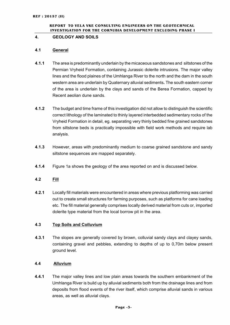
5.1.2 Table 2 overleaf gives a schedule of the laboratory testing.
REF : 20157 (II)
REPORT TO VELA VKE CONSULTING ENGINEERS ON THE GEOTECHNICAL
INVESTIGATION FOR THE CORNUBIA DEVELOPMENT EXCLUDING PHASE I
Page -6-
TABLE 2 : Schedule of Laboratory Testing
IP ¹ Depth
(m)
Description Test
Full
Grading
Mod
AASHTO CBR
79
0,80 -
1,00
Dark grey and orange brown,
moderately (partly completely)
weathered, soft rock Dolerite - (Karoo)
T T T
83 2,00 -
2,30
Orange, red and violet grey, completely
weathered, very soft rock DOLERITE -
(Karoo)
T T T
86 2,70 -
2,90
Grey brown, shattered, stiff, micaceous
very gravelly, slightly sandy silty CLAY
- (Residual Vryheid)
T T T
114 1,10 -
1,30
Very dark violet, and red, medium to
highly weathered, highly fractured soft
to medium hard rock DOLERITE -
(Karoo)
T T T
124
0,60 -
0,80
Dark grey, grey and yellow brown,
highly to moderately weathered,
completely weathered in joints, thinly
bedded, closely jointed, micaceous
soft to medium hard rock SHALE -
(Vryheid Formation)
T T T
162 1,80 -
2,00
Orange, completely weathered, very
soft rock DOLERITE - (Karoo)
T T T
187 1,10 -
1,30
Light yellow, orange red and grey,
highly weathered, very soft to soft rock
SANDSTONE / SILTSTONE - (Vryheid
Formation)
T T T
196 1,00 -
1,20
Yellow brown, medium weathered,
completely weathered on joints, thinly
bedded, closely jointed SANDSTONE -
(Vryheid Formation)
T T T
212 2,00 -
2,50
Dark grey brown, moderate to highly
weathered, highly fractured, soft rock
DOLERITE - (Karoo)
T T T
262 0,20 -
0,50
Brown, loose fine SAND - (Aeolian
Dune Sand)
T T T
270 0,60 -
0,80
Red brown, stiff, sandy CLAY - (Berea
Red Formation)
T T T
REF : 20157 (II)
REPORT TO VELA VKE CONSULTING ENGINEERS ON THE GEOTECHNICAL
INVESTIGATION FOR THE CORNUBIA DEVELOPMENT EXCLUDING PHASE I
Page -7-
5.1.3 The results of the laboratory testing are summarised in the Laboratory Test Summary
Table 3a to 3c, the Materials Analyses Figure’s 164 to 175 in Appendix 3, and are
discussed below.
5.2 Grading Analysis
5.2.1 Aeolian Dune Sands
5.2.1.1 The dune sand material encountered in IP 262 classifies as a very clayey fine grained
sand with a clay content of 24.1% and a grading modulus of 0.74. The material has a
plasticity index of 2.4
5.2.1.2 In terms of the Revised U.S. Classification this material is A-2-4(0) which is considered
excellent to good subgrade material.
5.2.2 Berea Red Formation
5.2.2.1 The Berea Red material encountered in IP 270 classifies as sandy clay with a clay
content of 63.4 and a grading modulus of 0.07. The material has a plasticity index of
18.4.
5.2.2.2 In terms of the Revised U.S. Classification this material is A-7-5 (21) which is
considered a highly compressible clay and therefore a poor subgrade material.
5.2.3 Dolerite
5.2.3.1 The dolerite materials encountered in IP 79, IP 162 and 212 classifies as slightly clayey
sands with a clay contents ranging from 0,6% to 5.8% and a grading modulus between
2.11 to 2.81 The materials have a plasticity index ranging from 6.4 to 9.5.
5.2.3.2 In terms of the Revised U.S. Classification all these materials are classify as A-2-4 (0)
materials, which is considered excellent to good subgrade material.
5.2.3.3 The dolerite material encountered in IP 83, however, classifies as a very sandy clay with
a clay contents of 27.5% and a grading modulus of 0.53. The material has a plasticity
index of 14.
5.2.3.4 In terms of the Revised U.S. Classification this material is A-6 (8) which is considered
fair to poor subgrade material.
REF : 20157 (II)
REPORT TO VELA VKE CONSULTING ENGINEERS ON THE GEOTECHNICAL
INVESTIGATION FOR THE CORNUBIA DEVELOPMENT EXCLUDING PHASE I
Page -8-
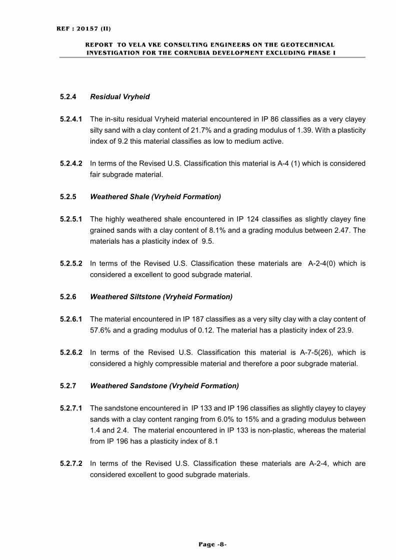
5.2.4 Residual Vryheid
5.2.4.1 The in-situ residual Vryheid material encountered in IP 86 classifies as a very clayey
silty sand with a clay content of 21.7% and a grading modulus of 1.39. With a plasticity
index of 9.2 this material classifies as low to medium active.
5.2.4.2 In terms of the Revised U.S. Classification this material is A-4 (1) which is considered
fair subgrade material.
5.2.5 Weathered Shale (Vryheid Formation)
5.2.5.1 The highly weathered shale encountered in IP 124 classifies as slightly clayey fine
grained sands with a clay content of 8.1% and a grading modulus between 2.47. The
materials has a plasticity index of 9.5.
5.2.5.2 In terms of the Revised U.S. Classification these materials are A-2-4(0) which is
considered a excellent to good subgrade material.
5.2.6 Weathered Siltstone (Vryheid Formation)
5.2.6.1 The material encountered in IP 187 classifies as a very silty clay with a clay content of
57.6% and a grading modulus of 0.12. The material has a plasticity index of 23.9.
5.2.6.2 In terms of the Revised U.S. Classification this material is A-7-5(26), which is
considered a highly compressible material and therefore a poor subgrade material.
5.2.7 Weathered Sandstone (Vryheid Formation)
5.2.7.1 The sandstone encountered in IP 133 and IP 196 classifies as slightly clayey to clayey
sands with a clay content ranging from 6.0% to 15% and a grading modulus between
1.4 and 2.4. The material encountered in IP 133 is non-plastic, whereas the material
from IP 196 has a plasticity index of 8.1
5.2.7.2 In terms of the Revised U.S. Classification these materials are A-2-4, which are
considered excellent to good subgrade materials.

REF : 20157 (II)
REPORT TO VELA VKE CONSULTING ENGINEERS ON THE GEOTECHNICAL
INVESTIGATION FOR THE CORNUBIA DEVELOPMENT EXCLUDING PHASE I
Page -9-
5.3 Mod AASHTO and CBR Test Results
5.3.1 Aeolian Dune Sand
5.3.1.1 The maximum Mod AASHTO density of the Recent dune sand is 1988 kg/m³ at an
optimum moisture content of 8.8 %.The material has a CBR of 3 at a compaction of
93% increasing to 5.8 at a compaction of 95% of the materials maximum Mod AASHTO
density. The material has a CBR swell of 0.81.
5.3.1.2 As such, in terms of TRH 14 (1985) the material meets the requirements of a G10 and
is therefore rated poor as subgrade, but suitable for bulk fill.
5.3.2 Berea Formation
5.3.2.1 The maximum Mod AASHTO density of the sandy clay of the Berea Formation is 1604
kg/m³ at an optimum moisture content of 22.4 %.The material has a CBR of 2 at a
compaction of 93% increasing to 2.3 at a compaction of 95% of the materials maximum
Mod AASHTO density. The CBR swell of the material is 4.
5.3.2.2 As such, in terms of TRH 14 (1985) the material does not meet the requirements of a
G10 and is therefore neither suitable as base, subbase or for any selected layers, nor
for use as subgrade material in road and pavement construction.
5.3.2.3 It must be noted that although the above results indicate that the Berea Formation
material sampled is poor material for use in road and pavement construction, the quality
of the Berea Formation materials may vary significantly. In this regard, suitable
material meeting the requirements of a G9/G10 soil may occur within the Berea
Formation.
5.3.3 Dolerite
5.3.3.1 The maximum Mod AASHTO density of the material encountered in IP79 and IP83,
ranges from 1735 to 1996 kg/m³ at an optimum moisture contents between 10.1 and
16.9%. The materials have a CBR values ranging from 6 to 28 at a compaction of 93%
a increasing to 6.5 to 41 at compaction of 95% of the materials maximum Mod AASHTO
density. The maximum CBR swell of the materials are between 0.44% to 1.55%.
5.3.3.2 As such, in terms of TRH 14 (1985) the material generally meets the requirements of
a G10 material but selectively, may be as good as a G6 material.

REF : 20157 (II)
REPORT TO VELA VKE CONSULTING ENGINEERS ON THE GEOTECHNICAL
INVESTIGATION FOR THE CORNUBIA DEVELOPMENT EXCLUDING PHASE I
Page -10-
5.3.3.3 The maximum Mod AASHTO density of the materials encountered in IP114 and 212
are ranging between 2115 kg/m³ and 2130 kg/m³ at optimum moisture contents
between 8.3% and 8.9%.The materials CBR values range between 21 and 44 at a
compaction of 93% as increasing to between 26 and 85 at compaction of 95% of the
materials maximum Mod AASHTO density. The material has no CBR swell.
5.3.3.4 As such, in terms of TRH 14 (1985) the material does meets the requirements of G6 (IP
212) and G7 (IP 114) gravel soils and are therefore both considered suitable for the use
as subgrade and in lower and upper selected layers in road and pavement construction.
5.3.4 Residual Vryheid
5.3.4.1 The maximum Mod AASHTO density of the residual in-situ material is 1936 kg/m³ at
an optimum moisture content of 11.9 %.The material has a CBR of 4 at a compaction
of 93% increasing to 4.9 at a compaction of 95% of the materials maximum Mod
AASHTO density. The CBR swell of the material is 1.2%.
5.3.4.2 As such, in terms of TRH 14 (1985) the material does not meet the requirements of a
G10 and is therefore suitable as subgrade material and for bulk fill only.
5.3.5 Weathered Shale (Vryheid Formation)
5.3.5.1 The maximum Mod AASHTO density of the weathered shale sampled is1999 kg/m³ at
an optimum moisture content of 10.7%.The material has a CBR values of 21at a
compaction of 93% increasing to 24 at a compaction of 95% of the materials maximum
Mod AASHTO density. The material have no CBR swell.
5.3.5.2 As such, in terms of TRH 14 (1985) the materials do not meet the requirements G7 and
are therefore suitable as selected layers and for use as subgrade material in road and
pavement construction.
5.3.6 Weathered Siltstone
5.3.6.1 The maximum Mod AASHTO density of the weathered material encountered in IP 187,
is 1507 kg/m³ at an optimum moisture content of 23.9%.The material has a CBR of 1
at a compaction of 93% increasing to 1.2 at a compaction of 95% of the materials
maximum Mod AASHTO density. The material has a CBR swell of 8.74%.
5.3.6.2 As such, in terms of TRH 14 (1985) the material does not meet the requirements of a
G10 and is therefore neither suitable as subbase, nor for any selected layers and for
use as subgrade material in road and pavement construction.

REF : 20157 (II)
REPORT TO VELA VKE CONSULTING ENGINEERS ON THE GEOTECHNICAL
INVESTIGATION FOR THE CORNUBIA DEVELOPMENT EXCLUDING PHASE I
Page -11-
5.3.7 Weathered Sandstone
5.3.7.1 The maximum Mod AASHTO density of the weathered sandstones encountered in
IP133 ranges is 1944 kg/m³ at an optimum moisture content of 8.7%.The materials has
a CBR values of 3 at a compaction of 93% increasing to 3.6 at a compaction of 95%
of the materials maximum Mod AASHTO density. The maximum CBR swell of the
material is 1.49%.
5.3.7.2 As such, in terms of TRH 14 (1985) the material classifies as a G10 material and is
therefore suitable for use as subgrade material only in road and pavement construction.
5.3.7.3 The maximum Mod AASHTO density of the weathered sandstones encountered in
IP196 is 1974 kg/m³ at an optimum moisture content of 10.5%.The materials has a CBR
of 3 at a compaction of 93% increasing to 3.6% of the materials maximum Mod
AASHTO density. The CBR swell is 2.13%.
5.3.7.4 As such, in terms of TRH 14 (1985) the material does not classify as a G10 material
and is therefore not considered suitable in road and pavement construction, but for bulk
fill use only.
6. GEOTECHNICAL ASSESSMENT
6.1 Development Proposals
6.1.1 No details other then general industrial and mixed residential development proposed
have been submitted to us.
6.1.2 The results of this investigation indicate that development in general is feasible on the
majority of the area reported on here. However, there are some geotechnical
constraints to the development which need to be taken into consideration in the
planning and implementation of the development. Such geotechnical constraints
include, but are not limited to the following;
6.2 Slope Stability
6.2.1 The bedrock Vryheid Formation underlying the area is in general laminated to thinly
bedded siltstone/shale or thinly bedded sandstone with dolerite intrusions.
Predominantly the sedimentary bedrock is closely jointed and inherently unstable, if cut
where the bedding plans are dipping out of the slope or embankments are over
steepened. No present or past conditions of instability could be observed, but might
have been invisible due to the dense cane on the site.

REF : 20157 (II)
REPORT TO VELA VKE CONSULTING ENGINEERS ON THE GEOTECHNICAL
INVESTIGATION FOR THE CORNUBIA DEVELOPMENT EXCLUDING PHASE I
Page -12-
6.2.2 In general the sedimentary bedrock of the Vryheid Formation is found to dip gently in
a northern or southern direction. Locally different dip directions can not be excluded.
6.2.3 However, slopes too steep for cane farming, should be considered unstable as
significant cutting and filling will be required to developed these areas.
6.3 Wetland and Conservation
6.3.1 Two major features should be considered as mainly wet areas and considered for
conservation areas:
C The low flood plains on the southern embankment of the Umhlanga River
C The major valley line systems, draining:
a) north towards the Umhlanga river
b) south towards the existing dam
6.3.2 These geomorphological features play important roles in flood protection for the existing
and proposed developments in periods of high water levels and floods.
6.3.3 Once sealed by development the absence of the water absorption of those flood plains
and major valley systems could cause major problems during periods of heavy rain and
unfortunate weather conditions and cause sever damage to existing and proposed
development.
6.3.4 We therefore suggest to limit all development to outside of the 100-year-flood- line and
initiate a re-naturalization towards the indigenous flora within the 100-year-flood-line to
the recreational benefit of the area and to prevent future damages by floods.
6.3.5 Minor wet drainage lines have been engineered on almost all slopes to optimize
commercial farming, prior to the present environmental regulations and concerns.
Although those drainage lines contains wet soils, no other wetland characteristics have
been observed.
6.4 Subsoil Activity
6.4.1 The results from the laboratory tests indicate that the residual material derived from
weathered Vryheid Formation bedrock and the Berea Formation clayey soils, generally
have a high clay content and are likely to be moderately to highly active. These soils will
in general be subjected to volume changes with changes in moisture content.
REF : 20157 (II)
REPORT TO VELA VKE CONSULTING ENGINEERS ON THE GEOTECHNICAL
INVESTIGATION FOR THE CORNUBIA DEVELOPMENT EXCLUDING PHASE I
Page -13-
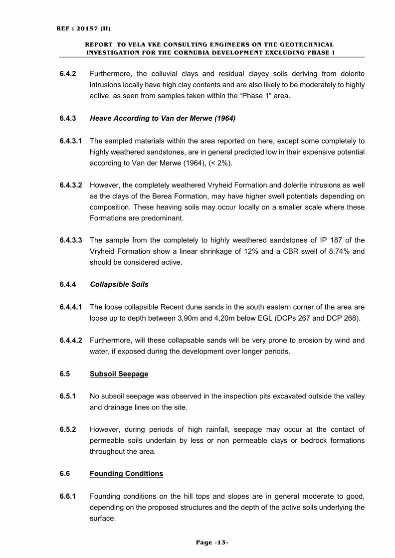
6.4.2 Furthermore, the colluvial clays and residual clayey soils deriving from dolerite
intrusions locally have high clay contents and are also likely to be moderately to highly
active, as seen from samples taken within the “Phase 1" area.
6.4.3 Heave According to Van der Merwe (1964)
6.4.3.1 The sampled materials within the area reported on here, except some completely to
highly weathered sandstones, are in general predicted low in their expensive potential
according to Van der Merwe (1964), (< 2%).
6.4.3.2 However, the completely weathered Vryheid Formation and dolerite intrusions as well
as the clays of the Berea Formation, may have higher swell potentials depending on
composition. These heaving soils may occur locally on a smaller scale where these
Formations are predominant.
6.4.3.3 The sample from the completely to highly weathered sandstones of IP 187 of the
Vryheid Formation show a linear shrinkage of 12% and a CBR swell of 8.74% and
should be considered active.
6.4.4 Collapsible Soils
6.4.4.1 The loose collapsible Recent dune sands in the south eastern corner of the area are
loose up to depth between 3,90m and 4,20m below EGL (DCPs 267 and DCP 268).
6.4.4.2 Furthermore, will these collapsable sands will be very prone to erosion by wind and
water, if exposed during the development over longer periods.
6.5 Subsoil Seepage
6.5.1 No subsoil seepage was observed in the inspection pits excavated outside the valley
and drainage lines on the site.
6.5.2 However, during periods of high rainfall, seepage may occur at the contact of
permeable soils underlain by less or non permeable clays or bedrock formations
throughout the area.
6.6 Founding Conditions
6.6.1 Founding conditions on the hill tops and slopes are in general moderate to good,
depending on the proposed structures and the depth of the active soils underlying the
surface.
REF : 20157 (II)
REPORT TO VELA VKE CONSULTING ENGINEERS ON THE GEOTECHNICAL
INVESTIGATION FOR THE CORNUBIA DEVELOPMENT EXCLUDING PHASE I
Page -14-
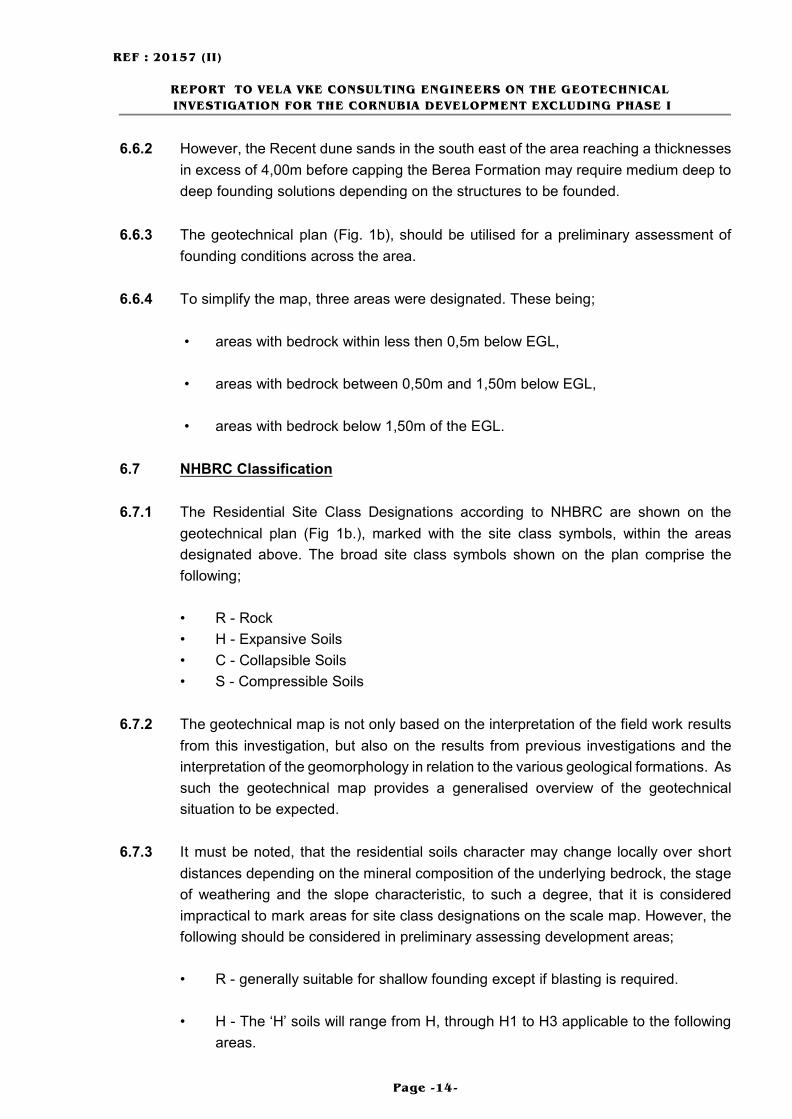
6.6.2 However, the Recent dune sands in the south east of the area reaching a thicknesses
in excess of 4,00m before capping the Berea Formation may require medium deep to
deep founding solutions depending on the structures to be founded.
6.6.3 The geotechnical plan (Fig. 1b), should be utilised for a preliminary assessment of
founding conditions across the area.
6.6.4 To simplify the map, three areas were designated. These being;
• areas with bedrock within less then 0,5m below EGL,
• areas with bedrock between 0,50m and 1,50m below EGL,
• areas with bedrock below 1,50m of the EGL.
6.7 NHBRC Classification
6.7.1 The Residential Site Class Designations according to NHBRC are shown on the
geotechnical plan (Fig 1b.), marked with the site class symbols, within the areas
designated above. The broad site class symbols shown on the plan comprise the
following;
• R - Rock
• H - Expansive Soils
• C - Collapsible Soils
• S - Compressible Soils
6.7.2 The geotechnical map is not only based on the interpretation of the field work results
from this investigation, but also on the results from previous investigations and the
interpretation of the geomorphology in relation to the various geological formations. As
such the geotechnical map provides a generalised overview of the geotechnical
situation to be expected.
6.7.3 It must be noted, that the residential soils character may change locally over short
distances depending on the mineral composition of the underlying bedrock, the stage
of weathering and the slope characteristic, to such a degree, that it is considered
impractical to mark areas for site class designations on the scale map. However, the
following should be considered in preliminary assessing development areas;
• R - generally suitable for shallow founding except if blasting is required.
• H - The ‘H’ soils will range from H, through H1 to H3 applicable to the following
areas.

REF : 20157 (II)
REPORT TO VELA VKE CONSULTING ENGINEERS ON THE GEOTECHNICAL
INVESTIGATION FOR THE CORNUBIA DEVELOPMENT EXCLUDING PHASE I
Page -15-
< ‘H’, ‘H1' - Areas underlain by shallow residual clayey soils, generally less
than 0,5m thick, overlying weathered shale and dolerite bedrock.
< ‘H2' - Areas underlain by residual clayey soils, generally between 0,5m
and greater than 1,5m thick, overlying weathered shale and dolerite
bedrock.
< ‘H3’ - Areas underlain by residual clayey soils, generally greater than 1,5m
thick, overlying weathered shale and dolerite bedrock.
• C - The ‘C’ soil will range from C, through C1 to C2 applicable to the following
areas.
< ‘C’, ‘C1' - Areas underlain by Berea Formation sandy clays and clayey
sands.
< ‘C2' - Areas underlain by loose Aeolian sands.
• S - The ‘S’ soil will range from S, through S1 to S2 applicable to the following
areas.
< ‘S’, ‘S1' - Areas underlain alluvial sands, clayey sands and clays less than
about 1.5 m thick.
< ‘S2' - Areas underlain alluvial sands, clayey sands and clays greater than
about 1.5 m thick.
6.7.4 Notwithstanding the above, it will be necessary to classify the soils on individual sites
or development areas as part of the detailed geotechnical investigation for the proposed
structures and or smaller development areas, within the Phase 2 area, as soon as
details for the proposed dwellings or structures are available.
6.8 Construction Material
6.8.1 Results from the laboratory test indicates that some residual clayey materials and the
completely weathered bedrock materials deriving from both Vryheid Formation rocks
(IP 196) and the dolerite occurring in the area classify as A-4, A-6 or A-7-5 soils in
terms of the Revised U.S. Classification. Furthermore the clayey sands of the Berea
Formation encountered classifies as a A-7-5 (21) material.
6.8.2 Locally weathered Vryheid Formation Shale and Dolerite bedrock materials classifies
as a G6/7 material, where the sand content is effectively high enough and is therefore
considered good for use as subgrade and for selected layers in road and pavement
construction.

REF : 20157 (II)
REPORT TO VELA VKE CONSULTING ENGINEERS ON THE GEOTECHNICAL
INVESTIGATION FOR THE CORNUBIA DEVELOPMENT EXCLUDING PHASE I
Page -16-
6.8.3 Flanders Quarry
6.8.3.1 Flanders Quarry is located in the central part of the area reported on here and is at
present not operational as a quarry/borrow pit. Drennan, Maud and Partners has been
involved in the development, monitoring and the past operation of Flanders Borrow Pit
since the early 1980's.
6.8.3.2 The borrow pit comprises an inclined sheet of dolerite that has intruded into the shale
and sandstones of the Vryheid Formation. It is approximately conformable to the
bedding of the sedimentary rocks of the Vryheid Formation and strikes north south
along the spur.
6.8.3.3 The type of mineral excavated from the borrow pit comprises weathered dolerite gravel,
suitable for the use in construction as G5,G6 and G7 gravel soils. To date, since the
monitoring of the borrow pit commenced by Drennan, Maud and Partners,
approximately 200,000 m³ of materials has been removed for construction in the area.
This has resulted in a significant cost saving to Tongaat Hulett Developments in the
development of the Umhlanga Ridge and Mount Edgecombe areas.
6.8.3.4 Both an extension of the Quarry to gain suitable construction materials, as well as
means to transform the Quarry area into a solid waste deposit have been discussed
during the past decade. How ever, prior to future development in that area, the existing
borrow pit needs to be rehabilitated.
6.8.3.5 For further information, we refer to the present owner Tongaat Hulett Developments
(Pty) Ltd.
6.9 Excavatability
6.9.1 The soils and weathered Vryheid Formation bedrock are locally excavatable to a depth
up to 3,20m below present ground level. However, the weathered bedrock does get
increasingly hard with depth and in places, where the bedrock is shallow, pneumatic
tools might be necessary for excavation.
6.9.2 The soils and weathered bedrock of the dolerite bedrock are locally excavatable to a
depth up to 3,20m below present ground level. However, the weathered bedrock does
get increasingly hard with depth and in places, where the bedrock is shallow, pneumatic
tools might be necessary for excavation.

REF : 20157 (II)
REPORT TO VELA VKE CONSULTING ENGINEERS ON THE GEOTECHNICAL
INVESTIGATION FOR THE CORNUBIA DEVELOPMENT EXCLUDING PHASE I
Page -17-
6.9.3 The Recent dune sands and the Berea Formation will be easy to excavate to depths in
excess of 4,00m below present ground level. However, due to the collapsable nature
of those materials, the recommendations given below for cut embankments must be
considered.
7. DEVELOPMENT RECOMMENDATIONS
7.1 Earthworks
7.1.1 No details of the proposed earthworks have been provided. However, a number of
individual building platforms or terraces are likely to be constructed. In this regard,
cutting and filling to balance the earthworks of individual platforms is likely to be the
most practical and economical earthworks solution. Careful planning of the earthworks
will therefore be required. This is not only necessary to ensure stability of cut and fill
bank, but also, in that it will be beneficial in that depth to founding below the final ground
level may be reduced.
7.1.2 Were possible, individual dwelling plots on the steeper slopes should be designed to
have their axes orientated in an up-downslope direction, rather then along the contours.
Therewith associated cut and fill slopes can be contained within individual plot
boundaries.
7.1.3 Cuts
7.1.3.1 Cut slopes in the colluvial and residual clayey materials, should in general be restricted
to a slope angle of 1:2 (26°). Steeper slopes may be created individually, at the
discretion of the Engineer. The maximum height of any cut slope should not exceed
about 3m without being assessed by the Engineer.
7.1.3.2 In the weathered sandstone and dolerite bedrock, the cut slopes may be increased to
1:1,5 (30°), or even steeper, up to 1:1 (45°) at the discretion of an Engineer.
7.1.3.3 However, it is essential to understand, that the close joint sets in the thinly bedded
Vryheid Formation bedrock may cause instability, if cut to unfavourable angles due to
adverse dip directions in the bedrock. We therefore recommend that during all cutting
of the site, excavations should be continually assessed by a Geotechnical Engineer or
Engineering Geologists.

REF : 20157 (II)
REPORT TO VELA VKE CONSULTING ENGINEERS ON THE GEOTECHNICAL
INVESTIGATION FOR THE CORNUBIA DEVELOPMENT EXCLUDING PHASE I
Page -18-
7.1.3.4 The excavation of excessively deep cuts in the Recent dune sands should be avoided
during the course of any development. Cut embankments in the loose aeolian sand must
be restricted to a slope batter of 1:2 (26°). Where recommended batters cannot be
accommodated, a retaining wall should be introduced. It is essential that any wall be
properly damped proofed and incorporates suitable surface drainage.
7.1.3.5 Cuts in the more sandy clays of the Berea Formation may be layed back to a slope batter
of no more than 1:1.75 (30°) at the discretion of an engineer. Such banks will however fail
in time as they loose their temporary cohesive strength, either by drying out or by
becoming saturated. As such any excavation deeper than about 1,20 m should therefore
be suitably battered back or shored to prevent the collapse of sides under adverse
conditions.
7.1.3.6 Cut embankments must be protected against surface erosion by the planting of vegetation
immediately after construction.
7.1.4 Fills
7.1.4.1 Prior to the placement of any fill, the in situ subsoil material containing vegetation
should be removed. The fills should then be constructed in layers a maximum of 300
mm loose thickness and be compacted to 93% of the materials Max Mod AASHTO
Density, prior to the placement of the next layer. The maximum slope angle of any fill
should be restricted to 1:1.5 (33°).
7.1.4.2 Where the natural ground slope exceeds a slope angle of 1:6 (10°), the fills should be
constructed on surface benched into suitable in-situ material.
7.2 Founding
7.2.1 Shallow Founding
7.2.1.1 Over most of the area outside the 100-year-flood-line concerned building platforms will
compromise a composite cut fill platform. Foundation for houses may compromise
normal strip footings taken down into competent weathered bedrock in cut, or through
fill and residual material into competent weathered bedrock.
7.2.1.2 The maximum allowable bearing pressure of foundations, taken through the residual
clayey soils into the weathered bedrock, requiring hard hand picking for excavation,
should be restricted to150kPa.

REF : 20157 (II)
REPORT TO VELA VKE CONSULTING ENGINEERS ON THE GEOTECHNICAL
INVESTIGATION FOR THE CORNUBIA DEVELOPMENT EXCLUDING PHASE I
Page -19-
7.2.1.3 However, where cut platforms are taken into hard slightly weathered sandstone or
dolerite bedrock may be increased to 250kPa, at the discretion of the engineer.
7.2.1.4 Typically, areas where shallow founding will be possible will be areas classified as R, H,
H1, C, C1 and S, S1.
7.2.2 Deep Founding
7.2.2.1 Where the depth to suitable founding exceeds the practical and economic depth for
normal strip footings, as may occur where deep colluvial and residual soils occur, (H2,
H3), the fill portion of the building platforms or alluvial soils (S, S1), as well as in the
collapsable loose sands (C2), in the south east, deep founding is required. In this regard,
the structures should be supported on ground beams spanning between deep column
base foundations, or, piled foundations, taken through all fill, colluvial, alluvial and
residual soils, and soft weathered bedrock, to bear into the firmly bedded weathered
bedrock at depth below the site.
7.2.2.2 Due to the likely expansive nature of the active clayey colluvial and residual soils
occurring in the area, these materials should not be used as fill beneath the surface
beds. Imported hard core or suitable in-situ weathered bedrock material is preferred for
this purpose.
7.2.2.3 The floor slabs for the structures should be isolated from all walls, ground beams,
columns and foundations to allow for any differential movements as may occur in the
expensive soils underlying the site. Similarly, all structures should incorporate regularly
placed expansion joints.
7.2.2.4 As an alternative founding measure, particularly on the lower portion of the site where
the highly active residual clays of the Vryheid Formation bedrock occurs, or where
structures span the prick of cut and fill on building platforms, suitably designed reinforced
concrete raft foundations are considered the most suitable type of foundation.
7.2.2.5 On cut fill platforms, the raft foundations should be supported on the fill side of the
building platform by short auger piles or pads, also taken down through the fill into
competent founding material such as weathered bedrock. This may also apply to the
dune sands and the Berea Formation materials in the south eastern corner.
7.3 Drainage and Erosion Control
7.3.1 Suitable subsoil drainage, storm water control and preventible solutions to avoid soil
erosion will be essential for most developments into the loose sands in the south eastern
area.

REF : 20157 (II)
REPORT TO VELA VKE CONSULTING ENGINEERS ON THE GEOTECHNICAL
INVESTIGATION FOR THE CORNUBIA DEVELOPMENT EXCLUDING PHASE I
Page -20-
7.3.2 Although not generally prone to erosion the in-situ soils deriving from the Vryheid
Formation and dolerite bedrock as well as weathered bedrock in the northern and
eastern parts of the area can nevertheless be gully or donga eroded by concentrated
uncontrolled water flow, especially in view of general steepness in some areas. It will
therefore be necessary to provide adequate stormwater surface drainage as part of the
infrastructural development of the area the discretion of the Engineer.
7.3.3 Due to the clayey nature of most of the subsoils on the site and taking into consideration
the environmental aspects of the partly densely developed surroundings, storm water
disposal by means of soakpits is in general not considered feasible. Stormwater from all
roof and paved areas should be piped or collected in surface drains to discharge into a
suitably designed storm water retention system where no efficient storm water system
exists.
7.4 Sanitation
7.4.1 The subsoil conditions prevailing in the predominantly clayey areas are such that subsoil
percolation disposal of septic tanks and waste water effluent by means of soak pits or
french drain trenches cannot be satisfactorily practised therein.
7.4.2 Regional waterborne sewerage should be installed throughout the area as part of its
development, also to protect the wetlands and possible recreational areas feeding or
surrounding the Umhlanga River from negative environmental impacts.
7.4.3 We also consider this necessary for the south eastern part underlain by the loose Recent
dune sands and clayey sands of the Berea Formation. Although percolation will be
sufficient, the environmental impact in this area could not be justified.
7.5 Road Construction
7.5.1 The results of the laboratory tests indicate that in general the colluvial and residual
clayey material, occurring at a relatively shallow level, on the site is considered poor as
a subgrade material in road construction and for use in bulk filling. As such, some
subgrade improvement will be required in these areas.
7.5.2 On the other hand, the Vryheid Formation bedrock materials with an effectively high
sand content are considered excellent to good as a subgrade material and suitable for
use in selected layers in road and pavement construction. The design of the road layer
works here should be based on a material classifying as a minimum G8/G9 gravel soil
in terms of TRH 14 1985 having a CBR value of about 10.

REF : 20157 (II)
REPORT TO VELA VKE CONSULTING ENGINEERS ON THE GEOTECHNICAL
INVESTIGATION FOR THE CORNUBIA DEVELOPMENT EXCLUDING PHASE I
Page -21-
7.5.3 Furthermore, the dolerite bedrock of most intrusions, including the existing borrow pit,
are considered excellent materials for road and pavement construction, if not completely
weathered to a silty clay.
7.5.4 The design of the road layer works here should be based on a material classifying as a
minimum G8/G9 gravel soil in terms of TRH 14 1985 having a CBR value of about 10.
7.5.5 We recommend that attempts are made to re-establishing and, if needed, extending
Flanders Quarry as a source of G5, G6 and G7 gravel soils for the proposed
development of the entire Cornubia Development.
7.5.6 Concluding Assessment
7.5.6.1 The above given development recommendations are of a general nature to cover
general trends throughout the entire area reported on.
7.5.6.2 The subsoil conditions may change locally and a detailed geotechnical investigation will
be required for each smaller units of the development as well as for each single complex
structures to establish the specific subsoil conditions to the specific proposed
developments or structures, as soon as those details are available and finalized.
8. CONCLUSIONS
8.1 The results of this geotechnical investigation confirm the general geotechnical conditions
underlying the areas of the proposed Cornubia Development excluding the “Phase 1"
area. In this regard, it is evident that the area is underlain by weathered sandstone,
siltstone and shale rocks of the Vryheid Formation intruded by dolerite during the
Jurassic. Furthermore, the south eastern slope is capped by the sandy clays and clayey
sands of the Berea Formation, which in areas are capped by Recent aeolian dune sands.
In addition, on the low plains and major valley lines of the site, alluvial soils overlie the
weathered bedrock.
8.2 No details of the proposed layout have been made available. However, the results of the
investigation indicate that for most of the area, provided the structures are optimally
located on cut and fill platforms, it will likely be feasible to found the structures at a
relatively shallow depth, into soft to medium hard bedrock. The maximum allowable
bearing pressure of foundations taken into the weathered bedrock, requiring hard hand
picking for removal, should be restricted to about 150 kPa. However, where shallow
founding is possible into weathered sandstones or dolerite the bearing pressure may be
increased to 250kPa at the discretion of an Engineer.
REF : 20157 (II)
REPORT TO VELA VKE CONSULTING ENGINEERS ON THE GEOTECHNICAL
INVESTIGATION FOR THE CORNUBIA DEVELOPMENT EXCLUDING PHASE I
Page -22-
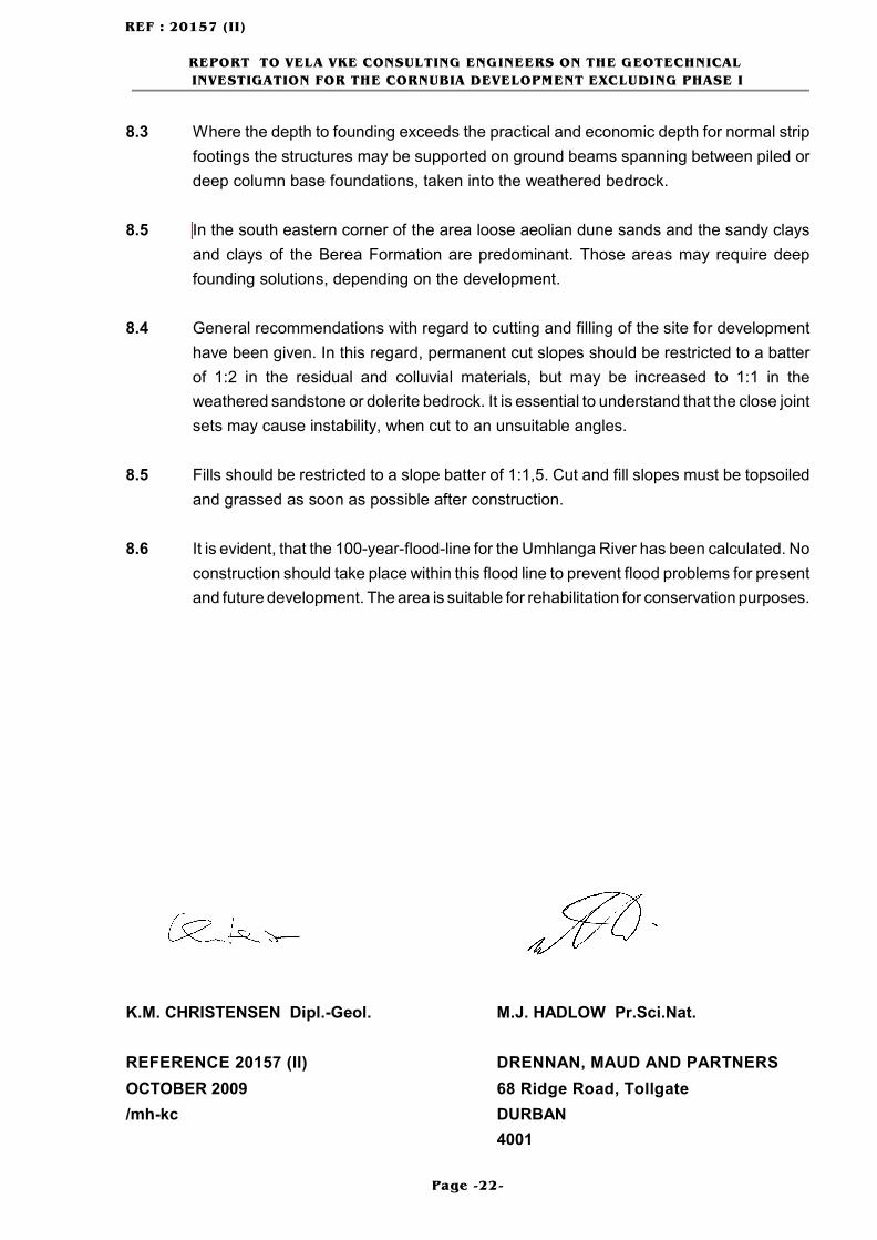
8.3 Where the depth to founding exceeds the practical and economic depth for normal strip
footings the structures may be supported on ground beams spanning between piled or
deep column base foundations, taken into the weathered bedrock.
8.5 In the south eastern corner of the area loose aeolian dune sands and the sandy clays
and clays of the Berea Formation are predominant. Those areas may require deep
founding solutions, depending on the development.
8.4 General recommendations with regard to cutting and filling of the site for development
have been given. In this regard, permanent cut slopes should be restricted to a batter
of 1:2 in the residual and colluvial materials, but may be increased to 1:1 in the
weathered sandstone or dolerite bedrock. It is essential to understand that the close joint
sets may cause instability, when cut to an unsuitable angles.
8.5 Fills should be restricted to a slope batter of 1:1,5. Cut and fill slopes must be topsoiled
and grassed as soon as possible after construction.
8.6 It is evident, that the 100-year-flood-line for the Umhlanga River has been calculated. No
construction should take place within this flood line to prevent flood problems for present
and future development. The area is suitable for rehabilitation for conservation purposes.
K.M. CHRISTENSEN Dipl.-Geol. M.J. HADLOW Pr.Sci.Nat.
REFERENCE 20157 (II) DRENNAN, MAUD AND PARTNERS
OCTOBER 2009 68 Ridge Road, Tollgate
/mh-kc DURBAN
4001

APPENDIX 1
INSPECTION PIT PROFILES
APPENDIX 2
DYNAMIC CONE PENETROMETER
TEST RESULTS

APPENDIX 3
LABORATORY TEST RESULTS

FIGURE 1A
GEOLOGICAL PLAN

FIGURE 1B
GEOTECHNICAL PLAN