Embed Size (px)
Citation preview
Report Out of the C4I Study Group
Donald H. TimianComputer Associates
5502 Leesburg Pike, Suite 1200Falls Church, VA 22041
(703) [email protected]
Joseph LaceteraMonmouth Science and Technology, Inc.
PMB 180, 328 South Main StreetBel Air, MD 21014
(443) [email protected]
Chris WertmanBooz-Allen & Hamilton
4301 N. Fairfax Drive, Suite 200Arlington, VA 22203
(703) [email protected]
Dr. Michael R. HiebIITRI/AB Technologies Group
1901 N. Beauregard StreetAlexandria, VA 2231
(703) [email protected]
Dr. Andreas TolkIndustrieanlagen-Betriebsgesellschaft mbH.
(IABG)Einsteinstr. 20
D-85521 Ottobrunn, [email protected]
Kevin BrandtThe MITRE Corporation
P.O. Box 51037Hampton, VA 23651
Keywords:C4I, C4ISR, HLA, JTA, M&S, C4ISR-to-Simulation FOM, M&S-to-C4I Interoperability, C4I/M&S
TRM, SISO M&S-to-C4I Interoperability SG, SIMCI, and SG-C4I
ABSTRACT: Simulation interfaces to Command, Control, Communications, Computers, Intelligence,Security, and Reconnaissance (C4ISR) systems are essential to support: Simulation Based Acquisition(SBA); the development of Doctrine, Tactics, Techniques, and Procedures (DTTP); “Train as you fight;”Embedded Training (both individual and collective); Course of Action Development and Analysis;Mission Planning and Rehearsal; and Execution Monitoring. Modeling and Simulation (M&S) systemshave standardized on certain protocols and architectures for interoperability, such as the High LevelArchitecture (HLA). Within the Department of Defense (DoD), the C4ISR community is also moving tostandardize on the Joint Technical Architecture (JTA) and the Defense Information InfrastructureCommon Operating Environment (DII COE). These interoperability efforts, as well as efforts within theDoD and the international community to standardize message formats and develop common M&S andC4I data models may – if the appropriate standards are identified and developed – significantly enhanceefforts to link M&S and C4ISR systems. However, a robust “two-way” dialog is required.
In order to assess “where we are and where we need to go” the Simulation Interoperability StandardsOrganization (SISO) charted an M&S-to-Command, Control, Communications, and Intelligence (C4I)Interoperability Study Group to: 1) provide background and current information on C4ISR andsimulation interoperability efforts; 2) provide a standards-based assessment of past and currentinteroperability efforts; and 3) make recommendations on how the Simulations Interoperability Workshop(SIW) C4I Forum should proceed with standards development activities. This paper is the report of theM&S-to-C4I Interoperability SG. It discusses “where we have been,” “where are we now,” “where weshould go,” and “how do we get there.” While the authors have collated submissions and edited thisreport, in truth it is the result of more than a dozen direct contributions in the form of draft sections andthe indirect contributions of the more than one hundred subscribers to the SG-C4I reflector.
Report Documentation Page Form ApprovedOMB No. 0704-0188
Public reporting burden for the collection of information is estimated to average 1 hour per response, including the time for reviewing instructions, searching existing data sources, gathering andmaintaining the data needed, and completing and reviewing the collection of information. Send comments regarding this burden estimate or any other aspect of this collection of information,including suggestions for reducing this burden, to Washington Headquarters Services, Directorate for Information Operations and Reports, 1215 Jefferson Davis Highway, Suite 1204, ArlingtonVA 22202-4302. Respondents should be aware that notwithstanding any other provision of law, no person shall be subject to a penalty for failing to comply with a collection of information if itdoes not display a currently valid OMB control number.
1. REPORT DATE JUN 2001 2. REPORT TYPE
3. DATES COVERED 00-00-2001 to 00-00-2001
4. TITLE AND SUBTITLE Report Out of the C4I Study Group
5a. CONTRACT NUMBER
5b. GRANT NUMBER
5c. PROGRAM ELEMENT NUMBER
6. AUTHOR(S) 5d. PROJECT NUMBER
5e. TASK NUMBER
5f. WORK UNIT NUMBER
7. PERFORMING ORGANIZATION NAME(S) AND ADDRESS(ES) Computer Associates,5502 Leesburg Pike Suite 1200,Falls Church,VA,22041
8. PERFORMING ORGANIZATIONREPORT NUMBER
9. SPONSORING/MONITORING AGENCY NAME(S) AND ADDRESS(ES) 10. SPONSOR/MONITOR’S ACRONYM(S)
11. SPONSOR/MONITOR’S REPORT NUMBER(S)
12. DISTRIBUTION/AVAILABILITY STATEMENT Approved for public release; distribution unlimited
13. SUPPLEMENTARY NOTES The original document contains color images.
14. ABSTRACT
15. SUBJECT TERMS
16. SECURITY CLASSIFICATION OF: 17. LIMITATION OF ABSTRACT
18. NUMBEROF PAGES
31
19a. NAME OFRESPONSIBLE PERSON
a. REPORT unclassified
b. ABSTRACT unclassified
c. THIS PAGE unclassified
Standard Form 298 (Rev. 8-98) Prescribed by ANSI Std Z39-18

1. Introduction
“The Simulation Interoperability StandardsOrganization (SISO) is dedicated to thepromotion of Modeling and Simulation (M&S)interoperability and reuse for the benefit ofdiverse M&S communities, includingdevelopers, procurers, and users, world-wide”[44]. Through the Simulation InteroperabilityWorkshops (SIW), SISO provides a forum forthe interchange of new ideas and conceptsacross a broad M&S community and lays thegroundwork for subsequent standardsdevelopment. As an intermediate step betweenthe papers presented at the semi-annualworkshops and standards development, SISOcharters Study Groups (SGs) to look at specificM&S issues that may ultimately bear on thedevelopment of standards. A key issue for boththe M&S and the Command, Control,Communications, Computers, Intelligence,Security, and Reconnaissance (C4ISR)communities is the interoperability betweenC4ISR systems and simulations. To address thisissue, SISO chartered a SG for M&S--to-C4IInteroperability (SG-C4I). This paper is thefinal report out of the C4I Study Group. Itdiscusses where we are, where we should go,and recommends how to get there.
1.1 Purpose of the SISO C4I Study Group
The SISO M&S-to-C4I SG was chartered inMarch 1999. The Study Group’s Terms ofReference [43] or goals, as specified by SISO’sExecutive Committee, are to:
� Recommend an approach or approachesthat will support an appropriate andsufficient level of interoperabilitybetween C4ISR systems and High LevelArchitecture (HLA) based simulations;
� Deliver a report which characterizesthe current “state of the art” of M&S-to-C4I interoperability; and
� Develop a categorical bibliography anda partial C4I/M&S interoperabilitylexicon. (Both to be publishedseparately.)
1.2 Structure of this Report
To satisfy the Study Groups goals, this reportwill:
� Provide background and currentinformation on C4ISR and SimulationInteroperability efforts;
� Provide a standards-based assessmentof past and current interoperabilityefforts; and
� Make recommendations on how theSimulation Interoperability Workshop(SIW) C4I Forum should proceed withM&S-to-C4I interoperability relatedstandards development.
To coherently build the case for standardsactivity recommendation(s) this report isorganized to answer the following questions:
Where have we been? In Sections 2.1, thereport contains a synopsis of the history of U.S.simulation and C4ISR interoperability in orderto provide the reader with a contrast to thecurrent state of interoperability between the twodomains.
Where are we now? In the remainder of Section2 and Section 3 the report describes a number ofrepresentative ongoing efforts and concepts.
Where should we go? In Section 4 we provide avision on how to achieve M&S-to-C4Iinteroperability and a C4I/M&S TechnicalReference Model (TRM) is described andrecommended for consideration by the M&Scommunity.
How do we get there? In Section 5 a set ofrecommendations on how to proceed arepresented.
2. Background and Issues
Motivation for improving the interoperabilitybetween simulations and C4ISR systemsinclude:
� Simulation Based Acquisition (i.e.,Requirements Development andAnalysis, Testing, and Training)
� Development of Doctrine and TacticsTechniques, and Procedures (DTTP)
� Train as you fight;� Embedded Training (both individual
and collective)� Course of Action Development and
Analysis� Mission Planning and Rehearsal; and� Execution Monitoring.
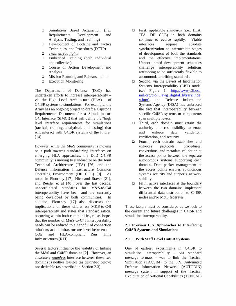
The Department of Defense (DoD) hasundertaken efforts to increase interoperability –via the High Level Architecture (HLA) – ofC4ISR systems to simulations. For example, theArmy has an ongoing project to draft a CapstoneRequirements Document for a Simulation-to-C4I Interface (SIMCI) that will define the “highlevel interface requirements for simulations(tactical, training, analytical, and testing) thatwill interact with C4ISR systems of the future”[14].
However, while the M&S community is movingon a path towards standardizing interfaces onemerging HLA approaches, the DoD C4ISRcommunity is moving to standardize on the JointTechnical Architecture (JTA) [26] and theDefense Information Infrastructure CommonOperating Environment (DII COE) [9]. Asnoted in Flournoy [17], Hieb and Staver [21],and Ressler et al [40], over the last decade,uncoordinated standards for M&S-to-C4Iinteroperability have been and are currentlybeing developed by both communities. Inaddition, Flournoy [17] also discusses theimplications of these efforts on M&S-to-C4Iinteroperability and states that standardization,occurring within both communities, raises hopesthat the number of M&S-to-C4I interoperabilityneeds can be reduced to a handful of connectionsolutions at the infrastructure level between theCOE and HLA-compliant Run TimeInfrastructures (RTI).
Several factors influence the viability of linkingthe M&S and C4ISR domains [2]. However, anabsolutely seamless interface between these twodomains is neither feasible (as described below)nor desirable (as described in Section 2.3).
� First, applicable standards (i.e., HLA,JTA, DII COE) in both domainscontinue to evolve rapidly. Viableinterfaces require absolutesynchronization at intermediate stagesof development of both the standardsand the effective implementations.Uncoordinated development scheduleschallenge interoperability solutionsattempting to be sufficiently flexible toaccommodate drifting standards.
� Second, via the Levels of InformationSystems Interoperability (LISI) model(see Figure 1; http://www.c3i.osd.mil/org/cio/i3/awg_digital_library/index.htm), the Defense InformationSystems Agency (DISA) has embracedthe fact that interoperability betweenspecific C4ISR systems or componentsspan multiple levels.
� Third, each domain must retain theauthority and responsibility to enactand enforce data validation,certification, and security.
� Fourth, each domain establishes andenforces protocols, procedures,conversions, and metadata validation atthe access points between the separateautonomous systems supporting eachdomain. Data packet management atthe access points enables autonomoussystems security and supports networkstability.
� Fifth, active interfaces at the boundarybetween the two domains implementdifferential data distribution to C4ISRnodes and/or M&S federates.
These factors must be considered as we look tothe current and future challenges in C4ISR andsimulation interoperability.
2.1 Previous U.S. Approaches to InterfacingC4ISR Systems and Simulations
2.1.1 With Staff Level C4ISR Systems
One of earliest experiments in C4ISR tosimulation interoperability – via standardmessage formats – was to link the TacticalSimulation (TACSIM) to the U.S. AutomatedDefense Information Network (AUTODIN)message system in support of the TacticalExploitation of National Capabilities (TENCAP)

program in 1980. TACSIM generated TacticalReports (TACREPs), Tactical ElectronicIntelligence (TACELINT), and a variety of othermessages in U.S. Message Text Format(USMTF) in both JANAP 128 and DOI 103formats, providing unclassified, classified
(collateral), and classified (SCI) text messagetraffic into the AUTODIN system.During an Ulchi Focus Lens exercise in Koreain 1990, this capability led to a direct linkage –via message translation – from TACSIM to theKorea Combat Support System (KCSS) and theKorea Air Intelligence System (KAIS) for key
Figure 1. Levels of Information Systems Interoperability (LISI) Model
(Manual)
4
3
2
1
0c
d
b
a
c
c
a
c
PProceduresrocedures AApplicationspplications II nfrastructurenfrastructure DDataata
(Universal)
(Integrated)
(Distributed)
(Peer-to-Peer)
Interoperability Attributes
DoD Enterprise
DomainService/Agency
Doctrine,Procedures,
Training, etc.
ProgramStandard Procedures,
Training, etc.
StandardsCompliant(JTA, IEEE)
SecurityProfile
N/A PrivateData
Basic Messaging(Plain Text, E-mail w/o
attachments)
BasicOperations
(Documents, Maps,Briefings, Pictures
Spreadsheets, Data)
Web Browser
Full Text Cut and Paste
Group Collaboration(White Boards, VTC)
Interactive(cross
applications)
LAN
Two Way
One Way
DomainModels
EnterpriseModel
NATOLevel 3
NATO Level 2
ProgramModels
andAdvanced
DataFormats
WAN
Multi-DimensionalTopologies
Network
BasicData
Formats
(DII-COE Level 5)
Compliance
Multi-NationalEnterprises
RemovableMedia
ba
LEVEL
cba
bao
Full Object Cut & Paste
AdvancedMessaging
(Parsers, E-Mail+)
ManualRe-entry
Shared Data(Situation Displays
Direct DB Exchanges)DBMS
b
CommonOperating
Environment
IsolatedLevel
ConnectedLevel
FunctionalLevel
DomainLevel
EnterpriseLevel
(Environment)
Cross-Enterprise
Models
Data File Transfer
NATOLevel 1
ManualAccess
Controls
Media ExchangeProcedures
Media Formats
No Known Interoperability
d
FederalEnterprise
Simple InteractionText Chatter, Voice, Fax, Remote Access,
Telemetry)

intelligence message traffic. KCSS andKAISwere the primary C4ISR systems whichsupported the Air Component Command (ACC)of the Korean Combined Forces Command(CFC). During this same event, there was alinkage developed and implemented between theAir Warfare Simulation (AWSIM) and TacticalReceive Equipment (TRE)/Tactical RelatedApplications (TRAP) systems. From TRAP, theinformation was fed through a TENCAP projectcomponent known as the Air Defense SystemsIntegrator (ADSI). This allowed enemy aircrafttracking data to be input to the air defense cellat the Control and Report Center (CRC). In thisway, there was established a direct linkage ofsimulation data to major operations andintelligence centers, including the intelligenceI&W centers, Electronic Combat Center,Control and Report Center, and CombatOperations.
Through the mid-1990’s, these techniques werecontinued and expanded with theimplementation of a Tactical InformationBroadcast Service (TIBS) data link from theAWSIM, along with a somewhat realisticrepresentation of threat emitters and thetransmittal of that information to ConstantSource (CS), Prototype Analyst Workstation(PAWS), Electronic Processing andDissemination System (EPDS), EnhancedTactical User Terminal (ETUT), and TacticalHigh Mobility Terminal (THMT). Many ofthese were developed by the Joint ElectronicWarfare Center (JEWC), in support of platformssuch as Rivet Joint, Senior Ruby, and GuardRail. Each of these efforts early allowedadditional simulation data to be fed directly to avariety of operational environments. But ineach case, the interface was one-way-only, fromthe simulation to the C4ISR environment.
In 1994, the Warrior Preparation Center built atwo way interface between AWSIM to theContingency Theater Automated PlanningSystem (CTAPS). The objective of the effort,known as Project Real Warrior (PRW), was tomaintain the existing simulation to C4ISRinterfaces, expanded those where possible, andto establish a database link from the CTAPS toAWSIM. The primary motivation behind thiseffort was the reduction of manpower within the
exercise response cells by providing anautomated entry of the Air Tasking Order(ATO) into AWSIM. Since the ATO cancontain upwards of 2000 missions per day, thisoffered a significant reduction in manpowerrequirements.
In parallel with this effort, the United States AirForce (USAF) Battlestaff Training School(BTS), known as “Blue Flag,” had anotherprogram, a CTAPS to Wargame InterfaceController (CWIC) working, which had similarobjectives to PRW, but with the added objectiveof providing automated synchronization ofdatabases between CTAPS and AWSIM. Thisallowed unit order of battle information to flowdirectly from CTAPS to AWSIM, simplifyingthe process, reducing time required for databasebuilds, and ensuring consistency between thetwo databases.
While these projects were occurring, in January1994 preparations were on going for an exercisein Japan, called Keen Edge. This was beingsupported by the Joint Warfighting Center(JWFC), using the Joint Theater LevelSimulation (JTLS). During an extremelyshortened development cycle (less than twomonths), a two way interface – using messageparsing augmented by database mapping – wasestablished between JTLS and CTAPS. Thisallowed an ATO, received from CTAPS, to betranslated into flight orders and routes for JTLS,and entered into the simulation. In turn,simulation generated Tactical Data Link(TADIL) formatted messages could be providedto operational personnel. In addition, enemyElectronic Intelligence (ELINT) data wasformatted and broadcast via operational links tothe entire TRAP network.
At about the same time, in support of the U.S.Army Text and Experimentation Command(TEXCOM), the Army Experimentation Station(AES) was developing a suite of interfaces,called the Simulation Support Modules (SSM),between a variety of C4ISR systems, the CorpsBattle Simulation (CBS), and the CombatService Support Training Simulation System(CSSTSS). The C4ISR systems stimulatedincluded, the All Source Analysis System(ASAS), the Maneuver Control System (MCS),the Advanced Field Artillery Tactical DataSystem (AFATDS), the Forward Area Air

Defense Command, Control, and Intelligence(FAADC2I) system, and the Combat ServiceSupport Control System (CSSCS). This suite ofinterfaces – via message parsing augmented bydatabase mapping – provided a two-way feedwith AFATDS (e.g., Calls for Fire) and a oneway feed with the other four systems. Theinformation provided from the simulationincluded status information, as well as a varietyof Command and Control (C2) actions.
These three early efforts in many waysinfluenced the development of the ModularReconfigurable C4ISR Interface (MRCI) [19 &31], which attempted to develop a standardizeddata output stream from a simulation to C4ISRsystems and to incorporate a standardizedmethod for converting C4ISR system inputs tothe simulations. This effort was initiallysupported by DMSO and later by the DefenseAdvanced Research Project Agency (DARPA).MRCI was demonstrated during the SyntheticTheater of War (STOW) 98 experiment. Whilemany aspects of the MRCI experiment weresimilar to earlier efforts in C4ISR to simulationinteroperability, there were two unique features.
One unique MRCI feature was the attempt todevelop a standard interface to the C4ISRenvironment, in contrast to previous efforts,which in general created unique interfaces toeach C4ISR system. The other unique aspectwas the attempt to develop and mature atechnology for translating command and controldirectives (or commands) into simulation“orders.” For this a tool known as theCommand and Control to Simulation InterfaceLanguage (CCSIL) was developed.
Concurrently, with MRCI the Air Force andArmy moved forward with a direct datadownload interface between AWSIM andCTAPS. Additionally, this two way interfacesent orders and commands to AWSIM whilepassing the status of the combat entities back toCTAPS in the correct format, with doctrinallycorrect content and timing.
In 1997 the Army began an effort to replace theSSMs. Called the Run Time Manager (RTM), itextended the SSM’s message parsing anddatabase augmentation by capturing information
via Distributed Interactive Simulation (DIS)Protocol Data Units (PDUs) and translatingembedded CCSIL-like data.
2.1.2 With Entity Level C4ISR Systems
While most of the discussion, to this point, onthe history of C4ISR to simulationinteroperability has dealt with staff level C4ISRsystems, there have been a number of efforts todevelop these interfaces at the entity, and eventhe engineering level.
One of the early efforts in this arena was thedevelopment of a Live-to-Virtual InterfaceDevice (LIVID) for use in the Army's 1995Focused Dispatch Advanced WarfighterExperiment (AWE). Focused Dispatch’s LIVIDprovided a voice and data interface between aSingle Channel Ground and Airborne RadioSystem (SINCGARS) radio and aCECOM/MITRE SINCGARS Radio Model(SRM). The LIVIDs, SRMs, and SINCGARSradio base stations were used together to link thevirtual and live domains. Both the realSINCGARS in the live environment and theSRMs in the virtual environment wereconnected to real C2 devises hosted on laptopcomputers. The SRM-LIVID linkage betweenthe C2 devices and the simulation environmentincluded a C2-system-specific interface, a corecommunications model, and a simulation-network interface.
This effort ran in parallel to, and was succeededby, the Tactical Internet Model (TIM) suite ofsimulation software. The TIM suite roots are inthe SRM, initially developed in support ofFocused Dispatch AWE. Later versions of TIMwere implemented to support not only training,but also analysis and testing. The TIM suiteprovided a realistic communicationsenvironment for training using Applique’ (thepredecessor to the Force XXI Battle CommandBrigade and Below (FBCB2) system), prior tothe Task Force XXI AWE. Follow-on effortshave incorporated FBCB2, as well as GlobalPositioning System (GPS) devices andHLA/Distributed Interactive Simulation (DIS)protocol-compliant simulations.
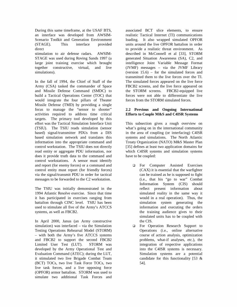
During this same timeframe, at the USAF BTS,an interface was developed from AWSIM-Scenario Toolkit and Generation Environment(STAGE). This interface provideddirectstimulation to air defense radars. AWSIM-STAGE was used during Roving Sands 1997 (alarge joint training exercise which broughttogether constructive, virtual, and livesimulations).
In the fall of 1994, the Chief of Staff of theArmy (CSA) tasked the commander of Spaceand Missile Defense Command (SMDC) tobuild a Tactical Operations Center (TOC) thatwould integrate the four pillars of TheaterMissile Defense (TMD) by providing a singlefocus to manage the “sensor to shooter”activities required to address time criticaltargets. The primary tool developed by thiseffort was the Tactical Simulation Interface Unit(TSIU). The TSIU reads simulation (sensorbased) signal/transmitter PDUs from a DISbased simulation network and translates thisinformation into the appropriate command andcontrol workstation. The TSIU does not directlyread entity or aggregate PDU information, nordoes it provide truth data to the command andcontrol workstations. A sensor must identifyand report (for enemy forces) or a command andcontrol entity must report (for friendly forces)via the signal/transmit PDU in order for tacticalmessages to be forwarded to the C2 workstation.
The TSIU was initially demonstrated in the1994 Atlantic Resolve exercise. Since that timeit has participated in exercises ranging frombattalion through CINC level. TSIU has beenused to stimulate all five of the Army’s ATCCSsystems, as well as FBCB2.
In April 2000, Janus (an Army constructivesimulation) was interfaced – via the SimulationTesting Operations Rehearsal Model (STORM)– with both the Army’s five ATCCS systemsand FBCB2 to support the second FBCB2Limited User Test (LUT). STORM wasdeveloped by the Army Operational Test andEvaluation Command (ATEC); during the LUT,it stimulated two live Brigade Combat Team(BCT) TOCs, two live Task Force TOCs, twolive task forces, and a live opposing force(OPFOR) armor battalion. STORM was used tosimulate two additional Task Forces and
associated BCT slice elements, to ensurerealistic Tactical Internet (TI) communicationsloading. It also wrapped simulated OPFORunits around the live OPFOR battalion in orderto provide a realistic threat environment. Asdescribed in McConnell et al [33], STORMgenerated Situation Awareness (SA), C2, andintelligence Joint Variable Message Format(JVMF) messages – via the JVMF Library(version 15.6) – for the simulated forces andtransmitted them to the live forces over the TI.The simulated forces appeared on the live forceFBCB2 screens, and the live force appeared onthe STORM screens. FBCB2-equipped liveforces were not able to differentiate the liveforces from the STORM simulated forces.
2.2 Previous and Ongoing InternationalEfforts to Couple M&S and C4ISR Systems
This subsection gives a rough overview onwhat’s going on in the international communityin the area of coupling (or interfacing) C4ISRsystems and simulations. The North AtlanticTreaty Organization (NATO) M&S Master Plan[35] defines at least two application domains forwhich C4ISR systems and simulation systemshave to be coupled:
� For Computer Assisted Exercises(CAX) it is essential that the warfightercan be trained as he is supposed to fight(i.e., that his “go to war” CombatInformation System (CIS) shouldreflect present information aboutsimulated reality in the same way itwould in a real operation). Thus, thesimulation system generating theinformation and executing the ordersthe training audience gives to theirsimulated units has to be coupled withthe CIS.
� For Operation Research Support toOperations (i.e., online alternativecourse of action analysis, optimizationproblems, what-if analyses, etc.), theintegration of respective applicationsinto the C4ISR systems is necessary.Simulation systems are a potentialcandidate for this functionality [53 &54].

2.2.1 NATO Efforts
Supreme Headquarters Allied Powers Europe(SHAPE) is planning to develop a CAX Centerfor training on joint operations at its level ofcommand. Within the CAX Center, the CIS ofSHAPE will be integrated, in part to insurerealistic training of commanders and theirforces.
Supreme Allied Commander Atlantic(SACLANT) realizes the coupling of itsMaritime Command and Control InformationSystem (MCCIS) with maritime simulationsystems using the Gold message format to sharenecessary information. Again, the applicationdomain is CAX.
NC3A is working mainly with JTLS and is alsofocusing on CAX. Under Project XC (CAX) atNC3A, the team has coupled several CIS andsimulations for exercise purposes using differenttechnical approaches.
2.2.2 National Level Efforts
France uses its Stradivarius simulation systemfor CAX applications as well as for after actionanalysis and simulation based acquisition. Oneof the purposes for developing this simulationsystem was to test the functionality andefficiency of the air defense system, includingradar’s, weapon systems, and command andcontrol. Thus, the interface to these air defensesystems has been an integral part of Stradivariusfrom its inception. Stradivarius supportsAdatP3 messages and Datalink (Surveillanceand Control): Link 1, Link 11, Link 14, Link 16and specific radar links.
Germany promotes the federation approach forthe coupling of C4ISR systems. It is one of theleading nations concerning data managementhaving already established a respective federalagency for data management (Daten-managementorganisation der Bundeswehr,DMO Bw).
� The same integration method used forC4ISR systems is also being used fordecision support simulation systems.
� For CAX purposes, alternative meansof stimulating C4ISR systems are beingevaluated. The use of standardmessage interfaces is one candidate and
the use of special domain areas withinthe databases (i.e., the definition of a“simulation system user” within theC4ISR system) is also being proposed.
� For the simulation systems, the GermanProposed Standard Interface forSimulation, introduced by [34], isplanned to become the standardinterface for linking M&S-to-C4ISR.
Italy is working on a federation solution usingATCCIS as a common shared data model. Insome areas, they are working closely togetherwith Spain. However, their work focusesexclusively on the integration of C4ISR systems.The use of simulations – to stimulate ItalianC4ISR systems – is only at the edge of the scope.
Netherlands coupled its KIBOWI system (Kivietand Borawltz; the two developers) with severalnational CIS. KIBOWI is similar to CAXsystem with a decision support system for onlineanalyses. The coupling is done by datareplication of respective data domains betweenthe two systems.
Portugal has no problem in coupling its CAXsystem Visualização Gráfica do Terreno emModelo Digital 3D (VIGRESTE) with AlliedTactical Command and Control InformationSystem (ATCCIS) compliant C4ISR system.The VIGIRESTE model developers choseATCCIS as the basis for the object model beingused within their simulation model. Thus, a realfusion approach is working that have beenplanned from the beginning. This was possiblesince Portugal started from scratch in both theC4ISR and CAX worlds with a harmonizedapproach.
Sweden participates in the Partnership-for-Peace(PfP) training efforts as a leading nation, usingTYR, a simulator to operate a game at commandlevel. Sweden has begun development of nextgeneration where HLA will be the architectureof the system. Sweden has also startedinvestigating how HLA can be a part of theSwedish Armed Forces C4ISR architecture andhow to apply a model based way of thinking inC4ISR-systems. ATCCIS is being considered inconnection with this work. Sweden is one ofthirteen members in the Western EuropeArmament Group (WEAG) EUCLID programCommon European Priority Areas (CEPA)

11:13 titled “Realising the Potential ofNetworked Simulation in Europe.”
The United Kingdom gained experience early onduring the FlasHLAmp experiments. WhereC4ISR systems were coupled with variouscombat simulations.
Many efforts are ongoing within theInternational community. However, theseefforts are largely uncoordinated. As a startingpoint, lessons learned should be shared amongnations through the SIW C4I and InternationalForum.
2.3 The NATO and DoD Modeling andSimulation Master Plans
In late 1994 and early 1995, the DefenseModeling and Simulation Office (DMSO)conducted a baseline assessment of all DoDM&S. From this assessment, DMSO identifiedsix DoD-wide M&S objectives that were, inOctober 1995, published in DoD's first M&SMaster Plan; DoD 5000.59-P, Modeling andSimulation Master Plan (MSMP) [10].
For each objective, DoD 5000.59-P identifieskey issues and actions [10]. Because no singlemodel or simulation can meet all of the needs ofthe M&S community, the objectives do notidentify any specific solution. Rather, eachobjective identifies those aspects that:
� Are common across all M&S (bothmilitary and non-military);
� Foster credibility and re-use [or costavoidance]; and,
� Where appropriate, ensureinteroperability.
DoD 5000.59-P establishes the HLA andConceptual Modeling of the Mission Space(CMMS) as, respectively, the first and secondcomponents of the DoD M&S TechnicalFramework [10 & 12].
Taking the DoD MSMP as one input, inNovember 1996, NATO began to develop aNATO MSMP. The Conference of NationalArmaments Directors (CNAD) established aSteering Group on NATO Simulation Policy andApplications with a mandate to craft an Allianceapproach to simulation in order to improve
Alliance operations. The resulting effortsresulted in the NATO Document AC/323(SGMS) D/2 [35]. It establishes a co-operativeapproach for applying advanced simulationtechniques to aid in satisfying the needs of theNATO Alliance and its member nations. It isassumed that successful execution of the masterplan will promote the aim of Alliance-widesimulation interoperability and reuse, while alsoproviding national and NATO bodies withsignificant modeling and simulation interest,with the necessary latitude to meet their specificneeds.
The NATO MSMP identifies four areas whereM&S can provide a “value added:”
� Defense Planning,� Training,� Exercises, and� Support Operations.
The objective to couple C4ISR systems andrespective simulation systems is an explicit topicfor the training, exercises, and supportoperations domains.
2.3.1 HLA
Objective 1 of the DoD M&S Master Plan states,“Provide a common technical framework forM&S.” Sub-objective 1-1 includes theestablishment of a common, high levelsimulation architecture to facilitateinteroperability of all types of simulationsamong themselves and with C4ISR systems, aswell as facilitate the reuse of M&S components.To meet this objective the Under Secretary ofDefense for Acquisition and Technology (USDA&T) designated the HLA as the standardtechnical architecture for all DoD simulations[26].
Future DoD C4ISR interface developers mustdevelop interfaces that take into account notonly the HLA, but also the DII COE and JTAmandated message formats, data models, anddata exchange standards.
2.3.2 Conceptual Models of the MissionSpace (CMMS)
CMMS provides simulation-independent,warfighter-based descriptions of the real world.

CMMS does this by linking Subject MatterExperts (SMEs) with simulation developers andusers via:
� Actual subject matter descriptions inthe form of knowledge acquisitionproducts;
� A common repository for use and re-use; and
� A technical framework for integrationand interoperability of the knowledgeacquisition products registered in thecommon repository [13].
Known as Mission Space Models (MSMs), thesesubject matter descriptions are the primarycomponents of DMSO’s CMMS program [23].Intended to describe how a specific task oraction is conducted, MSMs – via a hierarchicalform where each subordinate level, sub-process,or function provides greater detail – are the firstabstraction of real world processes [13 & 23].
With regard to M&S-to-C4I interoperability,MSMs – if used – have the potential to makepersonnel attempting to link M&S and C4ISRsystems realize that passing messages, whetherin the form of interactions or objects, betweensimulations and C4ISR systems is comparativelystraight forward. Far more difficultinteroperability problems are in the areas of
database synchronization, data cohesion, anddata collection (e.g., After Action Reviews).
2.4 JTA
The DoD JTA [26] has three mutuallysupporting objectives. The first is to provide thefoundation for interoperability and seamlessflow among all tactical, strategic, and sustainingbase systems that produce, use or exchangeinformation electronically. The second objectiveis to provide guidelines and standards for systemdevelopment and acquisition that willdramatically reduce cost, development time, andfielding time for improved systems. The thirdobjective is to influence the direction of theinformation industry’s technology developmentand research and development investment sothat it can be more readily leveraged in DoDsystems.
To better understand the role of M&S insupporting these objectives, we note that M&S isused, as shown in Figure 2, to support theanalysis and development of the real worldOperational Architecture (OA) and SystemArchitecture (SA) views. For example, for theOA view, information models are built (oftenusing IDEF0/IDEF1X) to represent real-worldsystems and the interfaces and the data flowbetween them. These models are of three basic
Figure 2. M&S Role in Support of the Operational, Systems, and Technical Architecture Views
Identifies Warfighter Needs
TechnicalArchitecture
Identifies Standards and Conventions
M&S
Standards!
Overlays Capabilities and RequirementsIAW Identified Standards
M&S Supporting SAIDEF0IDEF1X(JTA Section 2.4.2 -Information Modeling andData Exchange Standards:Activity Model, Data Model)
C4ISR CoreArchitectureData Model (CADM)OPNET
DII COE(JTA Section 2.4.2.5.2 -Information ProcessingStandards)
C2CDM(JTA Section 2.4.2 -Information Modelingand Data ExchangeStandards:Data Model)
HLA(JTA M&S Annex)
Systems Architecture
OperationalArchitecture
M&SSupporting OA

types: activity, data, and interface models.Activity models are representations of themission area applications or activities that anorganization must perform to achieve itsmission. They document processes and dataflows, can be validated against the requirementsand doctrine, and approved by the operationalsponsor. As such, they help define both what tobuild and the information flows necessary tosupport command and control of these units,based on requirements. The data models areused as a logical basis for physical dataexchange and shared data structures includingmessage formats and schema for shareddatabases. Interface models representconnection solutions at the infrastructure levelbetween the COE and HLA-compliant RTIs.For the SA view, M&S is used to develop the“wiring” diagram that shows how the variouselements communicate with one another, thusproviding the communications design for theunits and processes that the OA view specifies.However, it is unclear how the JTA applies tosuch uses of M&S.
The JTA provides a set of standards, some ofwhich are particularly relevant to M&S in theareas of data models and software architectures.For the C4ISR domain, these are specified in theJTA as the C4ISR common data models and theDII COE architecture. The DII COE consists ofcommon reusable software components. Withinthe JTA, M&S is a separate domain with its ownannex. In that annex the HLA is specified asthe set of relevant standards and the softwarearchitecture for M&S. However, the M&Sannex is not clear on the relationship betweenthe C4ISR domain and the M&S domain. Thishas led to confusion on which set of standardsapply to simulations, C4ISR systems, and C4ISRInterfaces.
2.5 DII COE
In JTA version 2.0 [26] DoD adopted theDefense Information Infrastructure CommonOperating Environment (DII COE) concept andmandated the DII COE baseline specificationand the DII COE integration and runtimespecification. The DII COE is missionapplication independent, as well as:
� An architecture;� An approach;
� A collection of reusable software;� A software infrastructure; and� A set of guidelines and standards.
Per the DII COE Architecture Oversight Charter[9], portions of the DII COE are being updatedusing requirements generated by 20 joint serviceTechnical Working Groups (TWGs). The Armyis the lead for several TWGs that are critical toM&S C4ISR interface developers, such as: theCOE Message Processor (CMP),Communications Services, Data AccessServices, and Alerts. There are also TWGs forthe Common Operational Picture; Visualizationand 3D; and Mapping, Charting, Geodesy, andImagery via the Joint Mapping Toolkit (JMTK).Just recently, the DII COE Executive OversightGroup established a new TWG – M&S – chairedby DMSO.
2.6 Information Assurance/Security
Information Assurance (IA) encompass allactions that “protect and defend information andinformation systems by ensuring theiravailability, integrity, authentication,confidentiality, and non-repudiation. Thisincludes providing for restoration of informationsystems by incorporating protection, detection,and reaction capabilities” [25]. Securitydemands an ability to tailor access to systemcomponents in concert with policy to enableforces to meet mission and/or trainingrequirements. Past efforts to link M&S andC4ISR domains have largely ignored IA/securityissues. The general focus has been on enablingconnections; not on establishing access securityor providing tools to ensure informationintegrity [2].
As more systems are linked, as applications areextended, and as more users are added, theimportance of information assurance grows. Inthe future, IA must be a major consideration indesigning links between and within M&S andC4ISR domains. Training objectives andpolitical goals will increase the need to linkfederations with multi-national forces whileeach force uses its native simulations and C4ISRsystems. This drive to extend the trainingaudience will not offset the need to “train as youfight.” Hence, multi-domain frameworks willdemand improved IA designs with security
features that permit authorized access whileenhancing protection.
Implementation of data filters within a domainhas significant performance implications [16].Hence, designs should include special securityfeatures at the intersecting boundary layersbetween domains. Thus, users and applicationswithin one domain may be correctly restrainedfrom access or interference within another.Hence, totally seamless links between domainsis not desirable. Rather, interfaces must striveto provide facile, automated, consistent accessacross these domain boundaries to authorizedusers and authorized programs.
Within the C4ISR domain, systems are based ona variety of protocols. These differences imposebarriers to interoperability within this singledomain. Addition of M&S components to thisequation will not resolve this C4ISRinteroperability issue. However, the DoDcommunity has taken strides to provide bothnear and long term solutions. The Office of theSecretary of Defense (OSD) and DISA haveworked to develop an interoperability model,LISI, discussed in detail in Section 4.3.Moreover, near term projects have implementedviable interfaces between disparate systems asdemonstrated by the Rosetta program in theLink-16/Variable Message Format (VMF)Conversion Advanced Concept TechnologyDemonstration [57]. However, this gateway
fails to include critical security features orrecord and monitor critical metadata. Thus inthe near term, reusable links between the HLARTI and target elements of the C4ISR domaincould leverage common gateways when theseextended with security features and metadatasupport. In the long term, other options may bedeveloped.
2.7 Relationship between C4ISR andSimulation Domains
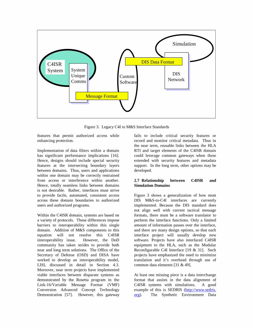
Figure 3 shows a generalization of how mostDIS M&S-to-C4I interfaces are currentlyimplemented. Because the DIS standard doesnot align well with current tactical messageformats, there must be a software translator toperform the interface functions. Only a limitedamount of information passes over the interface,and there are many design options, so that eachinterface project will usually develop newsoftware. Projects have also interfaced C4ISRequipment to the HLA, such as the ModularReconfigurable C4I Interface [19 & 31]. Suchprojects have emphasized the need to minimizetranslation and it’s overhead through use ofcommon data elements [31 & 49].
At least one missing piece is a data interchangeformat that assists in the data alignment ofC4ISR systems with simulations. A goodexample of this is SEDRIS (http://www.sedris.org). The Synthetic Environment Data
Figure 3. Legacy C4I to M&S Interface Standards
C4ISRSystem
Simulation
SystemUniqueComms
Message Format
DIS Data Format
DISNetwork
Custom Software

Representation and Interchange Specification(SEDRIS) could be a Data Interchange Format(DIF) between the simulation terrain formats(such as S1000 or Standard Interchange Format(SIF)) and the C4ISR terrain formats (DigitalTerrain Elevation Data (DTED) or VectorProduct Format (VPF)). Neither the simulationsnor the C4ISR systems use the SEDRIS format,but it allows conversion of data by providing aunifying representation.
There is a large difference in viewpoint betweenthe developers of Simulations and the developersof C4ISR systems, regardingapplicable
standards. C4ISR developers feel strongly thatsimulations should use the data elements thatreal systems use. This could lead to a standardsframework, as shown in Figure 4, with a DIICOE segment in the simulation for directdatabase-to-database data element transfer.
Figure 5 shows a standards basedinteroperability solution that is simulationoriented. It assumes that the HLA will behosted on C4ISR platforms, possibly as a DIICOE segment. But, the SG’s research indicatesthat C4ISR developers are not familiar with theHLA and have traditionally not accepted this asa valid requirement for their system.
Figures 4 and 5 also show that making a DIF –or an Application Programmer’s Interface (API)– a standard does not constrain the architecture.There will still be a need for a DIF even if onearchitecture predominates. Until botharchitectures have been designed with, and usethe same underlying data elements there will bea need for translation. However, a goodstandard will minimize translations.
Figure 4. A C4I Developer’s View of C4I to M&S Interface Standards
C4ISRSystem
Simulation
DII COECommsServer
DataInterchangeFormat
DII COECommsServer
Common Data Model

A framework must still be developed foraligning JTA M&S and C4ISR standards.
2.8 DoD Policy Concerning C4ISR andSimulation Interoperability
The labyrinth of interoperability policy canpresent many obstacles to unwary, unsuspectingC4ISR or M&S program managers, systemdevelopers, and users. Sutton [48] conducted ananalysis of military interoperability policy toprovide a roadmap of this complex, confusing,and often frustrating maze of policies.
2.8.1 C4ISR Interoperability PolicyElements
The following types of interoperability policyelements were found in C4ISR interopera-bility
policy documents, but not in M&S policy docu-ments:
� Certification and Re-certification� Compatibility� Doctrine� Integration� Interface Standards� Interoperability Problem Reporting� Interoperability Requirements� Interoperability Testing, Operational
Testing and Evaluation, Testing andEvaluation
� Mapping, Charting, Geodesy DataStandards and Specifications
� Mission Need Statement (MNS) andOperational Requirements Document(ORD)
� Interoperability Waivers
2.8.2 M&S Interoperability PolicyElements
The following types of interoperability policyelements were found in M&S interoperabilitypolicy documents, but not in C4ISR policydocuments
� Accreditation� Common Databases and Tools� Data Interchange Standards and
Protocols Establishment� Data Verification, Validation, and
Certification� Federations� HLA� Internet Standard and Protocol
Establishment� No-Pay/No-Play Deadlines for HLA
Conformance� Object Model Data Dictionary (OMDD)� Object Model Template Data
Interchange Format (OMTDIF)� Risk Management (Secretary of the
Navy Instruction (SECNAVINST)5200.38 only)
� Standard Simulator Data Base
Figure 5. A Simulation Developer’s View of C4I to M&S Interface Standards
C4ISRSystem
Simulation
HLARTI
DataInterchangeFormat
HLARTI
Federation Object Model

Interchange Format (SIF)� Synthetic Environment Data
Representation InterchangeSpecification (SEDRIS)
2.8.3 Interoperability Elements in bothC4ISR and M&S Policy Documents
The following types of interoperability policyelements were found in both C4ISR and M&Sinteroperability policy documents:
� Data Interchange Standards forApplications Sharing
� DII COE� Human-Computer Interface Standards� Information Modeling, Processing,
Systems Security, and TransferStandards
� Internet 5-Layer Network Model� Internet Standards and Protocols� Interoperable with Joint and Combined
C4ISR Systems and Operations� JTA� Open Systems Architecture Standards
and Protocols� Seamless, Transparent Open Systems
Infrastructure� Standard Data Elements Exchanged by
C4ISR Systems and M&S Applications� System Design and Integration Rules
for Technical Architecture
2.8.4 Interoperability Elements not in EitherC4ISR or M&S Policy Documents
The following types of interoperability policyelements were found to be missing from interop-erability policy directives in both domains:
� Technology Integration� Simulation Based Acquisition (SBA)� Formal Interoperability Theory and
Modeling� Interoperability Performance measure-
ment and standards
2.8.5 Interoperability Policy Consistency
Quantified interoperability performance meas-ures and metrics are not available in either theC4ISR or M&S domains. It is, therefore,impossible to measure and compare inter-operability performance in either domain; and
the effects of changes to interoperability policycan never be known or understood. C4ISRinter-operability policy defines detailed, explicitprocesses and procedures for achieving C4ISRsystem interoperability, but M&S policygenerally does not.
3. C4ISR-to-Simulation FOMs
This section includes a general discussion ofC4ISR FOMs under development, and theirimpact on M&S-to-C4I interoperability. (Acopy of each FOM is available for download athttp://www.sisostds.org/doclib/cat_display.cfm?id_number=48.)
3.1 A Prototype C4I FOM
The Prototype C4I FOM is the result of a U.S.Army requirement to develop a commonenvironment to facilitate the use of constructive,virtual, and live simulations in the evaluation ofC4I systems in the Research, Development, andAcquisition (RDA), the Advanced Concepts andRequirements (ACR), and the Training,Exercises, and Military Operations (TEMO)domains. To be effective, the simulationenvironment must be capable of interoperatingwith real C4I systems in a manner that isflexible, extensible, and promotes re-use ofsoftware components. The prototype C4I FOMis a step toward providing this capability byproviding a standardized representation forinteroperability that can be applied to a varietyof C4I systems.
The feasibility of the FOM to support this kindof objective simulation environment is currentlybeing demonstrated through an effort totransition the TIM to the HLA. A subset of theprototype C4I FOM, plus additional domain-specific classes and attributes, has been used asthe instantiation of the FOM for the TIMenvironment. The TIM environment provides arealistic interface to the virtual world for theArmy’s battalion and below C2 system, FBCB2.
In developing the initial version of the prototypeC4I FOM, object-oriented techniques were usedto gather requirements, synthesize the results,and map this information into a HLA FOMrepresentation. An Object-Oriented Analysis(OOA) and an Object-Oriented Design (OOD)

methodology was used to generate successivelayers of increasing detail, allowing for thecapture of many of the details of the problemdomain. The information was specified in amanner prescribed by the HLA Object ModelTemplate (OMT). Through this process certainkey areas were identified including C4I Systems,Communications Device, CommunicationsNetwork, Communications Effects, andMessages. Initially the FOM was focused onArmy lower echelon (battalion and below)exchange of Situation Awareness (SA) andbattle command messages through their C2systems. Included in the FOM were thespecification of the various categories ofcommunications equipment used (radios,routers, controllers), configuration of thenetworks (platoon, company, and battalion levelnetworks), and the effects on data transmissionresulting from the combination of environmentalfactors, network latency and traffic loading, andcharacteristics of the radio. As work on thiseffort continues during Fiscal-Year 2000(FY00), the scope of the FOM will evolve toinclude to some extent higher echelons (i.e.,brigade and division), Information Operations(IO), intelligence, and sensors. The currentversion of the prototype C4I FOM is availablefor viewing at the following SISO C4I StudyGroups Document Library:http://www.sisostds.org/doclib/ index.cfm.
3.2 TSIU FOM
The SMDC, Exercises and Training Division, isdeveloping an HLA compliant version of theTSIU. The TSIU provides a data interfacebetween the virtual simulation environment andthe Army Battle Command System (ABCS).
The concept of the TSIU is to translate thesimulation update data into the appropriatetactical format for transmission to tacticalC4ISR systems. Historically the TSIU hasreceived the simulation data via a predefined setof message updates utilizing a DISTransmitter/Signal PDU implementation. Theinformation from the simulation network istranslated and formatted by the TSIU and thentransmitted on a separate tactical network tolinked C4ISR systems. The TSIU provides allmessage formatting capability, thereforeeliminating the requirement for participatingsimulations to maintain the ever-evolving
tactical message format specifications.Following the modeling and simulationcommunity’s migration to the HLA, the TSIUprogram has recently implemented a prototypeC4ISR FOM to achieve a working HLAinterface to the simulation environment.
Building on previous simulation integrationexperience, the TSIU C4ISR FOM incorporatesmany of the data elements defined by theoriginal simulation message set. The simulationupdates, modeled exclusively as non-persistentHLA interactions, are defined by category andsupport a variety of tactical messageclassifications including Maneuver, Intelligence,Air Defense, Fire Support, and Combat ServiceSupport. The specific interaction parameters aredefined to a level of detail that supports efficientobject model expandability and generalreadability. In addition to the C4ISR FOMdevelopment, the TSIU has incorporated a FOMmapping capability, which will allow the TSIUto seamlessly integrate with other HLA FOMs,as future exercises require. Currently, the TSIUhas successfully integrated with SMDC’sExtended Air Defense Simulation (EADSIM)using the TSIU C4ISR FOM. Recent tests haveincluded the TSIU receiving maneuver andintelligence interaction updates from EADSIMand using the interaction data to generate andtransmit tactical messages to networked C4ISRsystems.
3.3 J6 NETWARS FOM
Network Warfare Simulation (NETWARS) is aJoint Chief of Staff modeling and simulationinitiative that has three objectives:
� Perform communication burdenassessment for a Joint Task Force(JTF),
� Analyze operational communicationplans, and
� Assess performance impact of newtechnology on JTF performance.
The underlying principle of NETWARS is thedevelopment of standard models that enhanceinteroperability and re-usability. TheNETWARS modeling standard defines classstructures from which a minimum set ofessential attributes is defined. For example, theradio class has transmission rate, power, and

modulation as its minimum set of attributes.The standard would also provide a commonnaming convention to facilitate NETWARSinterface with other models. Hence, adeveloper would use the minimum set ofattributes and would parameterize theseattributes appropriately when modeling aspecific radio.
The NETWARS FOM is based on this classdefinition and essential set of attributes.Depending on the type of models that are to befederated with NETWARS, this FOM providesthe necessary information to enhance theprobability of success when it is required tofederate with other modeling environments.
3.4 DII COE C4I FOM and the C4IAmbassador
The Naval Research Laboratory is developing aC4ISR FOM for DII COE based C4ISR systemsunder the sponsorship of DMSO and DISA.
The C4I Ambassador software provides two-waylinks between the embedded RTI and the DIICOE Services, data bases and C4ISR MissionApplications. It interprets the FOM (parses andreformats data as necessary) and managessimulated data distribution within C4ISR. Thisdevelopment builds on the technology containedwithin the recently released Global Commandand Control System (GCCS) EmbeddedTraining Segments for inserting training datainto operational GCCS systems.
3.4.1 Purpose
The (DII COE) C4I FOM and the C4IAmbassador are developed to embed the RTIand all necessary software within C4ISRsystems to allow them to function as Federateswithin an HLA Federation. The resulting C4ISRFederates provide the following interoperabilityfunctionality:
� Facilitates two-way interactionsbetween C4ISR systems andsimulations.
� Allows multiple, simultaneousFederates on a single C4ISR LAN.
� Provides both database-to-database andmessage based transactions.
� Processes real-time, faster than real-time and slower than real-timesimulated data.
� Ensures C4ISR mission applicationsrelate the same way to simulated andreal C4ISR data.
� Allows C4ISR Federates to reside andfunction within operational C4ISRwithout disrupting real worldoperations.
3.4.2 DII COE C4I FOM GeneralCharacteristics
The C4I FOM work originally began as theSimulation-C4I interface used in SyntheticTheater of War (STOW) 97 and 98 Exercises. Ithas progressed to be used for the Joint TheaterLevel System (JTLS) – GCCS Federation andthe Naval Simulation System – GCCS/MaritimeFederation. Work is underway to incorporatethis technology into the Navy Modeling andSimulation Management Office’s EmbeddedSimulation Infrastructure Program to movesimulations into GCCS/Maritime and the COE.Subsets of the overall C4I FOM are based onstandard military messages, database to databasetransactions and the Real Time PerformanceReference FOM (RPR FOM).
Database-to-database transactions yield thehighest level of interoperability potential. TheFOM design approach for this subset is to defineadditional objects and transactions for each newfederation in such a way that it is consistentwith C4ISR data content and internal databaseorganization. The objects defined to date aregenerally associated with military platforms andunits. The C4I FOM is composed of objects thatdirectly represent the Platform and Unit objectsstored in the DII COE Tactical DatabaseManager (TDBM).
There are also interactions in the FOM that areused to send platform position change requests(indirect control) to the simulation. Theseinteractions are modeled after routinelybroadcast real world orders such as PIM Track,Screen Kilo and Four Whiskey Grid. Inaddition, DII COE Federates have objectownership capabilities and the C4I FOM definesthe means for C4ISR to initialize scenarios,provide updates on real track behaviors, andcontrol forces during exercises (for those
simulations capable of supporting) theseinteractions.
3.5 Simulation-Based C2 IntegrationFramework
A team of researchers at the U.S. Air ForceElectronic Systems Center (ESC) recentlycompleted a prototype featuring AirborneWarning and Control System (AWACS)-relatedsoftware applications operating within asimulated battle. This effort represents a firststep toward a Simulation-Based C2 IntegrationFramework (SBCIF) for testing C2 systeminteroperability as MITRE and ESC team tomigrate existing Air Force systems to theIntegrated C2 System (IC2S).
MITRE internal research in Simulation to C2System Infrastructure is investigatingtechnologies, tools, and interface approachesnecessary to make the SBCIF vision a reality.With the trend in modern warfighting towardincreased C2 system interoperability, system-specific test harnesses traditionally used toexercise stovepiped C2 systems will no longersuffice. Instead, a synthetic battlespace isneeded that provides a more comprehensive,interactive battle environment within which C2systems can refine information exchangemechanisms and processes.
The synthetic battlespace within the SBCIF willbe composed of existing simulations connectedvia the HLA. C2 systems that have an HLAinterface capability will be able to takeadvantage of the SBCIF to exercise dataexchange capabilities within a realistic battleenvironment.
In the AWACS prototype, the battle is “fought”by a mission-level battle simulation. As thebattle plays out in real time, information aboutairborne platforms is pumped over a High LevelArchitecture (HLA) Runtime Infrastructure(RTI) to a real-time CORBA-based AWACSinfrastructure. There the data is parceled off toAWACS-related applications for processing anddisplay.
The AWACS effort demonstrates the potentialof the HLA as a mechanism for driving real-time C2 systems with simulated battle data for
testing, experimentation, training, and otherpurposes. With this prototype AWACS becomesthe first ESC system to achieve an HLAconnection to the SBCIF. Fully realized, theSBCIF will offer a wide variety of C2 systemsthe opportunity to take advantage of an HLA-based synthetic battlespace to refine operationalC2 capabilities.
3.6 Joint Theater Level Simulation (JTLS) -GCCS-NATO C2 Federation
The JTLS-GCCS-NATO C2 federation wasdeveloped to examine the use of the HLA tobuild interfaces between C2 systems andsimulations. The federation comprises a set ofmultinational command and control systems(GCCS and the NATO Consultation, Commandand Control Agency’s (NC3A) ICC Air Trackdisplay) and exercise support tools, stimulatedby JTLS. The federation is a partnership ofthree organizations, the DISA, the U.S. JointForces Command Joint Warfighting Center(USJFCOM/JWFC), and NC3A. Eachorganization has a vested interest in findingaffordable and extensible approaches to the taskof linking combat simulations to fielded C2systems to support training. DMSO joins thepartnership to provide the HLA, the enablingtechnology that serves as the foundation forlinking C2 systems to simulations.
3.6.1 Federates
The JTLS Combat Events Program (CEP) is thecore process of JTLS. The CEP does all themodeling of the combat units, the events, andthe battlefield environment. It contains thealgorithms for computing the state of simulationobjects, and reacts to orders created by humanoperators (players).
GDS, the G-Protocol Data Server (also calledthe Genis Data Server), is used as the datamanagement and distribution component of theJTLS system. The CEP sends state informationfor all simulation objects to the GDS. The GDS,in turn, services the information needs of anarray of simulation “clients,” including playerconsoles, data display terminals, and datatranslation modules that enable linkage toC4ISR systems.

The Global Command and Control System(GCCS) is the battlefield situation display andinformation management system for theater andjoint task force level commanders and theirstaffs.
The NC3A Order Translation Modules (OTMs)are a response-cell support tool that enables roleplayers to enter mission orders using more“natural” operational terms and graphics. TheOTMs then transform this data into a set oforders for subordinate units that can be executedin JTLS. The three OTMs that are included inthe federation represent land (LOTM), naval(NOTM), and air (OTMA) functionality.
The NC3A Aggregator is a response-cell toolintended to reduce the role players' workload bymaking it easier to discover and report statusinformation for aggregate units (made up ofseveral smaller sized units that are explicitlymodeled in the JTLS game). The aggregatorcalculates the status information for anaggregate unit from the data for the individualconstituent units.
The NC3A ICC Air Track Formatter is asoftware module that takes simulation state datafor aircraft, air missions, airbases, SAM sites,and radar sites as input and generates output inthe appropriate format for several NATO C4ISRdevices, including OPUS, ACBA, and ICC.
The NC3A Bi-MNC Report Generator is afamily of processes that translate a subset ofJTLS simulation data into well-structured,formatted NATO messages. These messagescan then be delivered to the training audiencevia real-world communications systems. Themodules accomplish the end-to-end process ofpreparing and injecting the reports into thecommunications backbone.
3.6.2 1999 Federation Activities
During 1999, the federation team workedtoward the goal of transitioning the federation tothe JWFC and NC3A for use in computer-aidedexercises. The JTLS team re-designed and re-implemented the RTI interface module toimprove stability and performance duringfederation execution. The GCCS teamexperimented with the implementation of a two-way data flow, allowing naval orders to be sent
from the GCCS workstation to the JTLS. TheNC3A team added two new federates, the Airand Naval Order Translation Modules (OTMs),to improve usability of the federation duringexercises. Finally, extensive testing during theyear helped to improve the performance andreliability of the federation with large exercise-level scenarios.
3.6.3 2000 Federation Activities
Immediate objectives for the federation are tofinalize the transition from the laboratory tooperational exercises. In the spring of 2000,NC3A deployed the federation in the first ofseveral NATO exercises. In addition, the JWFCis also examining potential applications of thefederation later in 2000. Both events willwarrant continued testing with an emphasis onimproving reliability, performance, anddeveloping a better understanding the potentialuses of the federation in an exercise. OtherHLA tools that would be new federates areunder evaluation as aids for monitoring thefederation and collecting data during execution.
3.7 Intelligence, Surveillance, andReconnaissance (ISR) Analysis FOM
The ISR FOM was developed to support thelinkage of legacy and newly developed federatesinto an analysis federation. This analysisfederation is intended to support the various,regularly occurring DoD and IntelligenceCommunity studies that have a need to be ableto analyze the impact of intelligencecommunity-derived information upon the battlein terms of quality, quantity, and timeliness ofrelated products.
This ISR FOM breaks out the various aspects ofthe intelligence cycle, and subdivides each intoits respective subordinate detailed processes. Assuch, this ISR FOM provides a taxonomy for theoverall intelligence cycle, to include thefollowing:
� Requirement/Concept of Operations(CONOPS) Analysis and Generation;
� Mission Planning;� ISR Sensor Collection;� Tasking, Processing, Exploitation and
Dissemination (TPED); and� Ground Truth.

3.8 FOM Alignment Summary
The FOMs reported in the previous sections arepotential sources of standard objects andinteractions. However, it is essential that firstthese FOMs be consistent among themselves.Here, we discuss how two of these FOMs arebeing, or can be aligned, to provide suchconsistency under an umbrella of a hypotheticalSISO C4ISR FOM. This “FOM” would thenprovide quasi-standards, or recommendedelements, that would facilitate the use of realsystems in constructive, virtual, and livesimulations.
The Prototype C4ISR FOM discussed in Section3.1 provides a good starting point in discussingcurrent and future FOM alignment. To beginwith, this FOM uses the RPR FOM BaseEntityclass hierarchy, with certain modifications. Asshown in its Object Model Identification Table,the developers added a CommUser class, an IWEffects hierarchy, and an updated C4IDevicehierarchy, adding various attributes to existingclasses and deleting extraneousENUMERATIONS inherited from the RPRFOM. This provides a broad-based commonalityfor any FOM that leverages off or aligns with
this C4I FOM. With a goal of general alignmentamong C4I FOMs, the C4I FOM developers andthe J6 NETWARS FOM developers haveengaged in an effort to align matching elementsof these two FOMs. For example, underexamination it was found that both FOMs haddefined similar variables albeit not always withthe same names. The following Table showssome of the observed alignment.
Prototype C4I FOM NETWARS FOMAntenna AntennaCommLink Communications LinkEndUserSystem End_SystemNetworkDevice Networking_Equipment
However, there are several cases where eachFOM defines a variable not defined in the otherFOM. For example, the NETWARS FOMdefines the variables ATM_Device, Satellite,and Hybrid_Model which were not initiallydefined by the C4I FOM. Further effort on thealignment of these FOMs will be required foreither of these FOMs to approach RFOM statusand to fit within the umbrella of the C4ISRFOM.

In summary, we have seen the beginning ofFOM alignment in the collaboration of theprototype C4I FOM and NETWARS FOMdevelopers. Lessons learned during the FOMalignment positively reinforce common designapproaches, criteria, and detail. Alignment ofother FOMs will increase the generalapplicability of the C4ISR FOM, create buy in ofmultiple potential FOM users and increase theFOMs critical mass required for Reference FOMstatus.
4. Vision
Our roadmap for improving the interoperabilitybetween simulations and C4I systems is shownin Figure 6 and our vision of an interoperableM&S-to-C4I framework is shown in Figure 7.
For the near term, Figure 6 depicts the currentlypredominant architectures in use for M&S-to-C4I interfaces. Such interfaces are mostlycustom “point-to-point” links that are often“black box” in nature. Simulation control is
basically one-way, with the simulationsinitializing the real C4ISR system databases.
In the mid term, we expect to see the HLAlinking constructive and virtual simulations onthe simulation side and, on the “real” side, theHLA, via common components found in C4ISRsystems (e.g., the DII COE Common MessageProcessor) also allowing C4ISR systems toexchange both data and messages withsimulations. Simulation initialization will betwo-way, with real system databases providinginformation to the simulation side.
Ultimately, as shown as “Far Term,” we expectto have full two-way linkages via commondatabases, thus achieving a higher measure ofinteroperability. As one would expect, Figure 6articulates only a broad vision of where M&S-to-C4ISR interoperability needs migrate to goover time. The Far Term is not an end state, but“is where we could be in 2010 to 2012, if we[the M&S and C4ISR communities] articulateour [joint] requirements and developcoordinated architectures and standards” [28].
Figure 6. The Road Ahead
“W here we are now and where we need to go.”
NEAR TERM
● Message Based● Black Box Link● Custom Point to Point● Limited 2-Way Feed● Sims Initialize C4I● Sims Update C4I
LegacyConstructive
LegacyVirtual
Platform
Platform
Constructive
Virtual
HLA
Platform
ConstructiveStrategic
Messages Database
Strategic
Both
Tactical Virtual
Live
Strategic
2001 2010
Tactical
HLA + Data Replication
FAR TERM
●Common Databases●Implicit Interoperability●Full 2-Way Exchange●Internal “Black Box”●Plug and Play L/V/C & C4I
TacticalCommon
Components
MID TERM
●Common Components●Consolidated Interfaces●2-Way Feed●Sims or C4I Initialize●Sims Update C4I●Common Standards

The figure is not meant to imply that C4ISRsystems have never been linked with livecomponents (i.e., tanks and infantry fightingvehicles), but that it is only in the far term thatwe expect “to see substantial progress inconstructing common interfaces to liveequipment such as weapons platforms” [28].
Finally, Figure 7 depicts our vision of aninteroperable M&S and C4ISR frameworkwhere interoperability is based on a commonconceptual reference model accommodatingcommon C4ISR component interfaces, commonstandards and tools, and aligned architectures,all linked via a common informationmanagement process to provide common, sharedsolutions for the C4ISR and simulationcommunities.
Whereas Figure 6 projects change over time andlists some of the components and elements thatmust result or support that change, Figure 7focuses on the concept of a comprehensivecollection of interdependent efforts that must beaddressed in parallel in order to achieveinteroperability.
Standards play a major role in interoperablesystems and are focused primarily in the bottomthree blocks of Figure 7. The SIW C4I Forumshould focus its efforts on “Alignment ofArchitectures,” “Common Data/Objects,” and“Common Standards & Tools.” It must beunderstood that a set of processes – “ProcessesFor Alignment & Migration” – executed by bothM&S and C4ISR agencies (e.g., DMSO and theDefense Information Systems Agency) mustaccompany the standards efforts to effect the
Figure 7. An Interoperable M&S and C4ISR Framework
SharedSolutions
ProcessesFor
Alignment& Migration
CommonData/Object
Models
Reusable Component Interfaces
Alignment of Architectures
Interoperabilityof Legacy and
Future Systems
M&S
C4I
CommonStandards
& Tools
Figure 7. An Interoperable M&S and C4I Architecture

change required for true M&S-to-C4Iinteroperability.
4.1 Towards M&S-to-C4I Data Alignmentand Interoperability
This sub-section presents a C4I/M&S TechnicalReference Model (TRM) for a complete C4ISRto simulation interface and also functionalrequirements for such an interface. Thisdiscussion will set the stage for the subsequentsections, and is intended to identify theinformation needed when interfacing systemsfrom the M&S and C4ISR domains.
To be specific, TRM is “a conceptualframework” that provides the following:
� A consistent set of service and interfacecategories and relationships used toaddress interoperability and open-system issues
� Conceptual entities that establish acommon vocabulary to better describe,compare, and contrast systems andcomponents
� A basis (an aid) for the identification,comparison, and selection of existingand emerging standards and theirrelationships [11].
4.1.1 Information Exchange Requirements
Prior to discussing specific standard softwarecomponents and data models, it is desirable firstto identify and classify the information that mustflow between M&S and C4ISR systems. Thiswill not be possible until there is a commonunderstanding of what constitutesinteroperability and the identification of one ormore technical reference frameworks. Second,in order for M&S developers to build internalinterface features that will work across a C4ISRdomain (and C4ISR developers to build in M&Sfeatures) the different types of information needto be standardized to some extent. DIFs such asthe Command and Control Simulation InterfaceLanguage (CCSIL) [32] need to be created forspecific information classes. We identify herethree broad classes that are necessary to meetconceptual requirements that would result inimproved interoperability:
� Persistent Data
� Non-Persistent Data� Execution Control
Persistent Data refers to the class of informationthat is stored during the operation of thesimulation. Information belonging to this classis typically initialized prior to execution andchanges less frequently, during simulationexecution, than Non-Persistent Data.
Non-Persistent Data refers to the class ofinformation that is transient, corresponding tointeractions between entities or objects in thesimulation or C4ISR database, or updates to anentity’s state.
The third class of information necessary for acomplete interface is Execution Control.Simulations typically have a set of protocols thatallow an operator to control the simulation’sexecution and/or synchronize it with othersimulations; including time managementfunctions. Current C4ISR systems do not haveprotocols that correspond to information classes;however, future C4ISR systems must have suchinformation classes/protocols to enable them tobe fully interoperable with simulations.
One example of this latter class is therequirement for After Action Review (AAR).While simulations can typically replay ascenario that had previously occurred, it is oftendesirable to synchronize C4ISR systems withthis playback to show the information availablefor decision making for particular events.Unless these requirements are specified toC4ISR developers, C4ISR systems may not havea capability to perform such operations.
Birkel [3] has developed a Synthetic NaturalEnvironment (SNE) Conceptual ReferenceModel that is very similar to the TRM describedhere. It is more focused on environmentaleffects but still is oriented towards interfacing toC4ISR systems. It provides an excellentcomparison and alternate viewpoint to the TRM.The TRM is more focused on informationexchange, while the SNE Conceptual ReferenceModel is more focused on functionality. TheSNE Conceptual Reference Modelauthoritatively extends the description of thoseclasses in the TRM that deal with the

environment (interfacing to physical andenvironmental models in the TRM).
Others have proposed models of C4I/M&Sinteroperability; many of those were reviewedduring the development of the TRM describedhere. Layman [29] discusses a model of aninterface for multi-level team training. Thismodel divides information into C2, TacticalCommunications, Combat Systems, and Sensorsclasses. These classes all fall into the Non-Persistent Data category in the proposed model.Farinacci, Roberts, and Winner [15] describe anarchitecture for establishing interoperabilitybetween a C4ISR system and CGF Simulationusing the HLA.
4.1.2 C4I/M&S Technical Reference Model
Figure 8 shows a notional Computer GeneratedForces (CGF) simulation with the types ofinformation that a complete interface mustaccommodate. The interface design is not
specified. The function of the interface is to 1)control the information flow between the C4ISR
system and the simulations and 2) to align theinformation among the systems so that theinformation is received in a system’s nativeformat. Note that all of the information mayflow bi-directionally. Thus M&S systems wouldneed to have the capability built to acceptinitialization data and orders from C4ISRsystems, as well as being able to pass scenarioinitialization data and messages to C4ISRsystems.
The notional CGF can be thought of as anexample of a current generation object-orientedsimulation, having different modules forExercise Control, Behaviors, Environment, andPhysical Models tied together with a Run TimeFramework. Persistent data is stored in aScenario Database. Current simulations, such asModSAF [7], can be easily mapped to thisnotional CGF. Each of the 12 separateinformation types is a candidate for a separateReference Federation Object Model (RFOM).Figure 8 depicts several other specific interfacerequirements:
Figure 8. A C4I/M&S Technical Reference Model
Simulation
C4I
Sy
stem
OrdersReports
Communications EffectsPhysical Models ModuleTracks
Non-Persistent Data
Behavior Models Module
Run Time Framework
Persistent DataUnit Data (OB, TOE, Symbology, etc)
Mission & Plan InformationComms Plan (Radio/Network Setup, etc)
Weather DataTerrain
Exercise Control Module
Exercise Control InteractionsInitialization/Execution
Data Collection
Imagery
Scenario DB
Communications Model
Environmental Models Module

� Exercise Control Interactions are atype of Execution Control that is passedto control the conduct of an event. Thecontrols would allow, for example,“checkpointing” of both simulationsand C4ISR systems, as well as allowingpausing of the C4ISR system atappropriate points in the exercise.Initialization and AAR protocols wouldalso fall in this category. ExerciseControl Interactions would beinterfaced to an Exercise ControlModule of a simulation. Logging isexplicitly identified as a separatecategory due to the importance of thisfunction.
� Orders are a type of interaction thatconvey C2 information. Translation ofthis class of information has beenextremely difficult to achieve withcurrent interfaces [4]. Presently,C4ISR systems do not support thegeneration and maintenance of this C2information in a uniform manner.
� Reports are a type of C2 informationabout the state of an entity. Themajority of current interfaces deal withthis class of situational awarenessinformation. Typical reportinformation includes location andstatus, and may be sent to the C4ISRsystem as either tactical messages ordata updates. Both Orders and Reportswould interface to Behavior Models ofa simulation, affecting the decisionmaking of simulated units. If thesimulation offers a high degree offidelity in C2, it may associate theseinteractions with CommunicationEffects.
� Imagery is a type of unprocessed visualC2 information from a sensor. Thisdata is characterized by high bandwidthrequirements and the need to beprocessed or analyzed prior to use.Imagery would also interface toBehavior Models of a simulation,affecting the decision making ofsimulated units. Examples of thiswould be video from an Unmanned
Aerial Vehicle (UAV) or a MovingTarget Indicator (MTI) radar imagefrom a Joint Surveillance and AttackRadar System (JSTARS) [56].
� Track Data is information regardingthe physical state of entities (orobjects). This class of information alsoincludes physical interactions betweenobjects (such as weapon effects). Asimulation may need to know thelocation of a live unit, even if it is notsending out report messages (Reports).Alternatively, air tracks of a simulatedaircraft may need to be generated for aradar screen. If the data passed to theinterface is ground truth, then the datashould have effects applied to turn thedata into perceived truth. Theseinteractions would be processed by thePhysical Models Module of asimulation.
� Communication Effects (CE) emulatethe characteristics of thecommunications channel by which theinformation in classes Orders andReports are passed [6 & 42]. In mostcases, a CE interaction would be pairedwith a C2 interaction. This interactionwould be interfaced to a physical devicemodel (such as a radio model) thattransmits or receives the CEinteraction, in the Physical Models ofthe simulation.
� Persistent Data covers a wide varietyof information. This usually includesOrder-of-Battle (OB) information aswell as specification of the terrain to beused. Typically this information is notexchanged in current interfaces, butrather is manually aligned. As anexample, a C4ISR system will have anOB database, and a simulation willhave a completely differentrepresentation of these units. It shouldbe possible to initialize the simulationfrom a C4ISR system, just as a C4ISRsystem should be able to be populatedwith exercise data from a simulation.Persistent Data would be initialized atruntime and kept current during

execution. This class of informationwould interface to the simulation’sScenario Database, as well as theEnvironmental Models Module fordynamic updates during execution.Persistent Data includes: Weather Data– essential for training exercises;Communications Laydown – needed forinitializing communications networksso that communication effects can bemodeled; Mission and Plan information– necessary for generation of orders;Unit Data – including the OB andassociated information; and TerrainStandards. Interchange of terrainformats has been problematic withinthe simulation domain as well as withinthe C4ISR domain.
4.2 Incorporating Metadata
The proposed technical reference modelidentifies three broad classes of data. The lackof a fourth class of orthogonal data inhibits fullinteroperability. Metadata, or data about thedata, is needed. The M&S community and theC4ISR users go to great lengths to certify theirinitial databases. Yet, as soon as interactivesimulations start, data changes. Few systemstoday track these changes in detail. Fewer stillreport these changes with accompanyingmetadata to targeted C4ISR systems. Withoutmetadata, subscribers cannot ensure that RTIdata originates from the “correct” source withina federation. Without metadata, C4ISR systemsmay not be able to determine where the dataentered the system and who within the systemshould receive it. Moreover, these systems maynot be able to determine priority of the data orthe very nature of the data (simulation dataversus real-world information). Thus, metadatatags must record state-of-the-world informationfor each piece of critical data. These data itemsinclude, but are not limited to, authorizedsource(s), version numbers, date and time,destination, authenticated observers, etc.
4.3 LISI Model
While not explicitly developed to codify cross-domain links to M&S, the LISI model (Figure 1)provides a reasonable framework to scope the
needed level of connectivity. In general, lowerlevels of interoperability require increasedmanual intervention to maintain links.However, higher levels of interoperability arenot free. In general, they impose requirementsfor recurrent coordination between independentprograms, increased levels of engineeringdevelopment, and robust configurationmanagement.
LISI identifies four domains: Procedures andPolicy, Applications, Data, and Infrastructure(PAID) which impact on information exchange.As suggested in Figure 1, a level ofinteroperability exists within each of the PAIDdomains. Unfortunately, the interoperabilityachieved between two systems is dependent onthe lowest level attained within the fourdomains. Thus, use of a “sneaker net” to passinformation between systems of differentsecurity levels is not unusual, even though theapplications, infrastructure and data may becommon. This then attests to the impact of thelowest domain level and the appropriateness ofconsidering all four domains.
Thus far, the C4I/M&S TRM focuses on dataexchanges. As the LISI model suggests, thisinadequately addresses interoperability betweentwo systems. Given the LISI model was notdeveloped to classify links between the M&Sand C4ISR domains, these connections maydrive extensions to the LISI metric. Potentialexpansion of LISI warrants further study byDMSO, in conjunction with DISA, to classifylinks between M&S components and standardgateways. Extension should allow the LISImodel to fully capture potential connectionsbetween systems built to common standards.
4.4 Communications Interoperability
Communications is often treated separately inM&S-to-C4I interoperability. In modelingcommunications there is a body of expertiseseparate from that used for developing interfacesto C4ISR systems. In addition, many currentC4ISR interfaces do not includecommunications considerations. In this sub-section we discuss three different aspects relatedto communications: 1) communicationsmodeling; 2) communications effects; and 3)
communications content. Additional issuesassociated with communication interoperabilityinclude system and simulation interfaceanomalies (induced by the insertion ofsimulations into the C4ISR architecture),fidelity, and connectivity between the “real” andsimulated environments (i.e., a gateway device).
Communications modeling focuses onrepresentation of communications elements suchas communications equipment, traffic, topology,and protocols. Typical uses include theassessment of measures of performance, such aslatency, utilization, throughput, etc. This can beaccomplished through abstractions of theinformation passed between C4ISR systems andnetworks. Often communications is notsimulated in real time. Communicationsmodeling can be performed with or without aninterface to C4ISR systems and/or networks.
Communications effects focus on theenvironment’s impact on communicationstraffic. For example, a radio transmission maybe degraded due to propagation losses resultingfrom terrain and atmospheric effects. Othertypes of degradation include increased latencydue to network loading and routing, thecharacteristics of the radio (i.e., bit error rate orthe radio’s signal to noise ratio), andinterference and jamming.
Communications content of the informationtransaction is another consideration forcommunication interoperability. The spectrumof content can range from the specific size orformat of the message to the actual messagecontent. For example, message formats fortactical data link or imagery can be generated bya simulation and transmitted to a C4ISR systemthat would, in real life, have to process theinformation.
5. Recommendations
Over the last 20 years M&S and C4ISR havebeen linked via:
� Standard message formats;� Message translation;� Message parsing augmented by
database mapping;
� Translation of C2 directives (e.g.,Call for Fire) into simulation“orders” (CCSIL); and
� Data replication.Obviously, better interoperability standardsbetween M&S and C4ISR systems are necessary,but not sufficient. Both simulations and C4ISRsystems must increase their functionalcapabilities [5]. For example, simulations mustimprove their reporting capabilities, and C4ISRsystems must become aware of simulationconstructs like exercise control.
In order to foster better understanding betweenthe M&S and C4ISR communities, recommendthat the SIW C4ISR Track collaborate with theU.S. Assistant Secretary for Defense forCommand, Control, Communications, andIntelligence (ASD(C3I)) sponsored Commandand Control Research and TechnologySymposium to help further M&S-to-C4Iinteroperability and to investigate jointstandards development.
In addition, develop a set of SISO M&S-to-C4Iinteroperability “recommended practices” and/orstandards by:
� Creating a SISO M&S-to-C4IInteroperability TRM from theC4I/M&S TRM described in Section4.1.2. This TRM should include afourth broad data class, Metadata asdescribed in Section 4.2 and considerthe LISI model.
� Creating a SISO guide to linking M&Sand C4ISR systems via standardmessage formats, data replication, etc.
� Using both the Prototype C4I FOMdescribed in Section 3.1 and the J6NETWARS FOM described in Section3.3 as starting points, create a SISOC4I Reference FOM that provides aframework under which Base ObjectModels (BOM) (e.g., a radio class) canbe incorporated.
6. References
[1] Anderson, J.R., Anderson, T., and Hardin,G.: “The Tactical Simulation InterfaceUnit (TSIU) Program,” Paper 00F-SIW-

046, 2000 Fall Simulation InteroperabilityWorkshop, 2000.
[2] Brandt, K.: “Modeling and SimulationLinks with Command and Control (C2)Systems: Considerations in ArchitectureDesign,” Paper 99F-SIW-181, 1999 FallSimulation Interoperability Workshop,1999.
[3] Birkel, P.: “SNE Conceptual ReferenceModel,” Paper 98F-SIW-018, 1998 FallSimulation Interoperability Workshop,1998.
[4] Carr, F.H. and Hieb, M.R.: “Issues andRequirements for Future C4ISR and M&SInteroperability,” 7th Conference oncomputer Generated Forces and BehavioralRepresentation, 1998.
[5] Carr, F.H. and Hinton, L.G.: “StimulatingC4I Systems and Achieving Control of theSimulated Battlefield,” Paper 97F-SIW-136, 1997 Fall Simulation InteroperabilityWorkshop, 1997.
[6] Carr, F.H. and Roberts, J.D.,“Incorporating Command and Control intothe High Level Architecture: AnArchitecture for Realistic CommunicationEffects,” Paper 97F-SIW-076, 1997 FallSimulation Interoperability Workshop,1997.
[7] Ceranowicz, A.: “ModSAF Capabilities,”4th Conference on Computer GeneratedForces and Behavior Representation, 1994.
[8] Christopherson, T. and Dacunto, L.J.:“Simulation, Testing, Operations,Rehearsal Model (STORM),” Paper 98S-SIW-027, Spring 1998 SimulationInteroperability Workshop, 1998.
[9] Defense Information Infrastructure (DIICOE) Architecture Oversight Charter,Office of the Defense Information SystemsAgency, http://diicoe.disa.mil/coe/aog_twg/aog/aog_page.html, January, 1997.
[10] Department of Defense (DoD) 5000.59-P,DoD Modeling and Simulation MasterPlan, http://www.dmso.mil/documents/policy/ msmp/index.html/, 1995.
[11] Department of Defense (DoD), DoDTechnical Reference Model Version 1.0,Defense Information Systems Agency, 5November 1999, http://www-trm.itsi.disa.mil.
[12] Defense Modeling and Simulation Office(DMSO) Information Paper, “Conceptual
Models of the Mission Space,”ftp://ftp.dmso.mil/pub/documents/initiatives/cmms/98s_siw_infoprp.pdf/, 1998.
[13] Defense Modeling and Simulation Office(DMSO) Information Paper, “ConceptualModels of the Mission Space,”ftp://ftp.dmso.mil/pub/documents/initiatives/cmms/cmms_information_paper_short.pdf, 1998.
[14] Loental, D. and Leath, R.: Simulation ToC4I Interface (SIMCI) CapstoneRequirements Document, (Draft),TRADOC Analysis Center, 14 October1999.
[15] Farinacci, M.l., Roberts, J.D, and Winner,B.R.: “Incorporating Command andControl into the High Level Architecture,”Paper 96-15-021, 15th Workshop on theInteroperability of Distributed InteractiveSimulations, 1996.
[16] Ferguson P. and Huston, G.: “Quality ofService: Delivering Quality of Service onthe Internet and in Corporate Networks,John Wiley & Son, New Your, 1998.
[17] Flournoy, D.: “Reconciling EmergingInfrastructure Standards to Promote C2-to-Simulation Interoperability,” Paper 98F-SIW-027, 1998 Fall SimulationInteroperability Workshop, 1998.
[18] Hieb, M.R. and Blalock, J.: “DataAlignment between Army C4I Databasesand Army Simulations,” Paper 99S-SIW-034, 1999 Spring SimulationInteroperability Workshop, 1999.
[19] Hieb, M.R., Cosby, M., Griggs, L.,McKenzie, F., Tiernan, T., and Zeswitz,S.: “MRCI: Transcending Barriersbetween Live Systems and Simulations,”Paper 97S-SIW-197, 1997 SpringSimulation Interoperability Workshop,1997.
[20] Hieb, M.R. and Sprinkle, R.: “SimulationInfrastructure for the DII COEArchitecture: The Army Vision,” Paper00F-SIW-035, 2000 Fall SimulationInteroperability Workshop, 2000.
[21] Hieb, M.R. and Staver, M.J.: “TheArmy’s Approach to Modeling andSimulation Standards For C4I Interfaces,”Paper 98F-SIW-259, 1998 Fall SimulationInteroperability Workshop, 1998.
[22] Hieb, M.R. and Timian, D.H.: “UsingArmy Force-on-Force Simulations to

Stimulate C4I Systems for Testing andExperimentation,” Paper 1999 Commandand Control Research and TechnologySymposium, 1999.
[23] Johnson, T.H.: “Mission Space ModelDevelopment, Reuse, and the ConceptualModels of the Mission Space Toolset,”Paper 98S-SIW-155, 1998 SpringSimulation Interoperability Workshop,1998.
[24] Johnson, T.H. and Might R.J.:“Requirements Analysis, Mission SpaceModels, and the CMMS: What’s This AllAbout?,” Article Fall 1999 MSIAC M&SOnline Journal, http://www.msiac.dmso.mil/journal/cmms.html/, 1999.
[25] Joint Publication 1-02, Department ofDefense Dictionary of Military andAssociated Terms, June 14, 2000.
[26] Joint Technical Architecture, Versions 1.0,2.0. 3.0, and 3.1, Defense InformationSystems Agency, http://www-jta.itsi.disa.mil, 31 March 2000.
[27] Krusche, S. and Tolk, A.: “A SHADEApproach for Coupling C4I-Systems andSimulation Systems,” Paper 99F-SIW-004,Fall 1999 Simulation InteroperabilityWorkshop, 1999.
[28] Lacetera, J. and Timian, D.H.: “InterimReport Out of the C4I Study Group,” Paper00S-SIW-060, 2000 Spring SimulationInteroperability Workshop, 2000.
[29] Layman, G.E., Conover, J., Kunkel, P.,and Robins, D.: “JMCIS/GCCSInteroperability with ExternalSimulations,” Paper 97S-SIW-132, 1997Spring Simulation InteroperabilityWorkshop, 1997.
[30] Legaspi, A.K. and Ivancic, C:“NETWARS C4ISR CommunicationModeling Standard,” Paper 98F-SIW-017,2000 Fall Simulation InteroperabilityWorkshop, 2000.
[31] Lightner, M., Schanduaa, J., Cutts, D., andZeswitz, S.: “The High Level ArchitectureCommand and Control Experiment –Lessons Learned in Designing anExtended Federation,” Paper 98S-SIW-93,1998 Spring Simulation InteroperabilityWorkshop, 1997.
[32] MITRE: 1997 DARPA CFOR/CCSIL athttp://ms.ie.org/cfor/, 1997.
[33] McConnell, J., Riehl, M., Hoang, T.,Tafoni, T., and Lacetera, J.: “A Model for
Interfacing a C4I System to TacticalCommunications Simulations,” Paper 00F-SIW-064, 2000 Fall SimulationInteroperability Workshop, 2000.
[34] Menzler, H.P., Krosta, U., and Pixius, K.:“HLA in a Nutshell: Proposed StandardInterface for Simulation,” Paper 00S-SIW-026, 2000 Spring SimulationInteroperability Workshop, 2000.
[35] North Atlantic Treaty Organization(NATO) Document AC/323 (SGMS) D/2,NATO Modelling and Simulation MasterPlan (Version 1.0), http://www.dmso.mil/NATO_MSMP/ msmp, 1998
[36] Newcomb, M., Gustafson, J., and Nguyen,P.: “The WARSIM C4I Interface,” Paper99F-SIW-036, 1999 Fall SimulationInteroperability Workshop, 1999.
[37] Ogren, J.W.: “Command and StaffTraining and the Practical Use of theHLA,” Paper 00F-SIW-061, 2000 FallSimulation Interoperability Workshop,2000.
[38] Piece, J. and Wood, E.: “The TIM Suite –A Federation for Live/Virtual Simulationof C4I Systems,” Paper 00F-SIW-066,2000 Fall Simulation InteroperabilityWorkshop, 2000.
[39] Paola, A.R. and Ressler, R.L.:“Stimulating the Army Tactical Commandand Control System Using the Run TimeManager: Concepts and Implications,”Paper 98S-SIW-162 1999 SpringSimulation Interoperability Workshop,1999.
[40] Ressler, R., Hieb, M.R., and Sudnikovich,W.: “M&S/C4ISR Conceptual ReferenceModel,” Paper 99F-SIW-060, 1999 FallSimulation Interoperability Workshop,1999.
[41] Shen, B., Sudnikovich, W., and Kennedy,L.: “Transition to The Objective C4IModeling and Simulation Environment,”ITSEC98, December 1998.
[42] Silva, W. Steigerwald, A., Cosby, M. Hieb,M.R., and Lacetera, J.: “CommunicationEmulation Design in the MRCI Program,”Paper 97F-SIW-160, 1997 Fall SimulationInteroperability Workshop, 1997.
[43] Simulations Interoperability StandardsOrganization (SISO) Command, Control,Communications, Computers, andIntelligence (C4I) Study Group Terms of
Reference, Vision,http://www.sisostds.org/ doclib/index.cfm.August 1999.
[44] Simulations Interoperability StandardsOrganization (SISO) Vision,http://www.sisostds.org/doclib/doclib.cfm?SISO_FID_2383, May 5, 1999.
[45] Stanzione, T. and Chamberlain, F.:“Composable Synthetic NaturalEnvironments for Computer GeneratedForces,” 7th Conference on ComputerGenerated Forces and BehavioralRepresentation, 1998.
[46] Sudnikovich, W. and Roberts, J.:“Implementation of a prototype C4I FOM:Continued Progress,” Paper 99F-SIW-077,1999 Fall Simulation InteroperabilityWorkshop, 1999.
[47] Sudnikovich, W., Roberts, J., andLacetera, J.: “Implementation of aprototype C4I FOM,” Paper 99S-SIW-061,1999 Spring Simulation InteroperabilityWorkshop, 1999.
[48] Sutton, P.W.: “Interoperability PolicyRoadmap,” Paper 00S-SIW-157, Spring2000 Simulation InteroperabilityWorkshop, 2000.
[49] Thumim K., Clay, B., Hieb, M.R., andCosby, M.: “Modular ReconfigurableMessage Translation: Translation ofMessages Between C4I Systems andSimulations,” Paper 97F-SIW-120, 1997Fall Simulation Interoperability Workshop,1997.
[50] Timian, D.H.; Hicks, M.W., and Hieb,M.R.: “An Approach for Using DII COEComponents to Link Simulations and C4ISystems: A Case Study Using the CMP,”Paper 00F-SIW-011, 2000 Fall SimulationInteroperability Workshop, 2000.
[51] Timian, D.H., Hieb, M.R., Glass, J., andStaver, M.J.: “Using Standard C4IComponents to Interface to Simulations,”Paper 98F-SIW-035, 1999 SpringSimulation Interoperability Workshop,1999.
[52] Tolk, A.: “HLA-OMT versus TraditionalData and Object Modeling – Chance orShoehorn?,” Paper 00S-SIW-024, Spring2000 Simulation InteroperabilityWorkshop, 2000.
[53] Tolk, A.: “Requirements for SimulationSystems when being used as Decision
Support Systems,” Paper 99F-SIW-002,1999 Fall Simulation InteroperabilityWorkshop, 1999.
[54] Tolk, A. and Schiefenbusch, K.:“Decision Support Systems – Concepts andEffects,” XXXVIII. Army OperationsResearch Symposium, 1999.
[55] Wertman, C.: “History and Background ofC4I-to-Simulation Interoperability,”C4ISR Track Invited Speaker Presentation,2000 Spring Simulation InteroperabilityWorkshop, 2000.
[56] Williams, M.: “Proposal for MovingTarget Indicator and Synthetic ApertureRadar C4I Imagery Sensor Federations forHLA,” Paper 98S-SIW-019, 1998 SpringSimulation Interoperability Workshop,1998.
[57] Yannni, P.: “A VMF/Link-16/Simulation Gateway; Addressing theComplexity of Datalink Interoperability,”Paper 99S-SIW-068, 1999 SpringSimulation Interoperability Workshop,1999.

7. Acknowledgements
While the authors have collated submissions andedited this report, in truth it is the result of morethan a dozen direct contributions in the form ofdraft sections and the indirect contributions ofthe more than one hundred subscribers to theSG-C4I reflector. Needless to say, it isimpossible to thank or mention all of theindividuals that contributed to this report.Nonetheless, below is list of individuals withoutwhose contributions and efforts this reportwould have impossible to write:
Tonya Anderson Andy BowersJohn Bott Nikhil DaveVerlynda Dobbs Larry DworkinDoug Flournoy Jerry ForbesZach Furness Larry GoldbergCarl Ivancic Gene LaymanBob Leath Albert LegaspiDave Loental Tom MullinsLiesel Muth Gary ParkerMary Jean Rackley John RobertsRick Severinghaus Fred SmithRon Sprinkle Ed SowellTim Spollen Bill SudnikovichPaul Sutton Ken SullivanJeff Vogel Gary Waag


![C4i. 2 [lect.] p id 0 idea creation](https://img.dokumen.tips/doc/110x75/55617502d8b42a98268b4a04/c4i-2-lect-p-id-0-idea-creation.jpg)