Embed Size (px)
Citation preview
PROJECT REPORT
ON
Study of electrical system in power plant
SUBMITTED BY:
VANYA GUPTA
SUMMER TRAINEE B.TECH THIRD YEAR
ELECTRICAL AND ELECTRONICS ENGG
GURU TEGH BAHADUR INSTITUTE OF TECHNOLOGY

CERTIFICATE
We would like to express my appreciation to Ms. VANYA GUPTA (Summer Trainee) for her enthusiasm and dedication to her quality of work during the Project Work. This report has presented a comprehensive STUDY of ELECTRICAL SYSTEM in POWER PLANT. We wish her all the success in future.
P K GAUTAM RAJIV NIRMAN Manager DGM PEM Electrical PEM Electrical

ACKNOWLEDGEMENT
I hereby take this opportune moment to express our deep sense of gratitude to our Department Head Mr. K.K KHURANA (AGM-Electrical) for his unstinted support and
encouragement I express my heartfelt thanks to Mr. RAJIV NIRMAN (DGM) for being a source of guidance and inspiration during this period. His wonderful style of mentoring has surely made our training period a great learning experience. I would also like to give my due concern to Mr.PK GAUTAM (MANAGER), who have supported me in the completion of my project. The close cooperation from Ms. MANDVI GUPTA (Senior Engineer) & Mr. RAM KUMAR YADAV (Engineer) for their technical guidance and encouragement which has been of great help in carrying out the project work. I express my sincere thanks to all the members of electrical department for their friendly and helpful attitude. Finally, I wish to thank my parents for their continuous undivided support and encouragement, which inspired me to go my own way. Without them it would not be possible to complete this project.
Vanya gupta
Date: Summer Trainee
B.Tech (3rd year)
GTBIT

Table of Contents
Abstract
Sr.no TOPIC PAGE NO.
1. INTRODUCTION TO BHEL
2. INTRODUCTION TO PEM
3. OVERVIEW OF ELECTRICAL SYSTEM
4. M.V SWITCH GEARS
5. RATING OF BREAKERS IN HT
6. L.V SWITCHGEARS
7. RATING OF BREAKERS IN LT
8. PROTECTION OF L.V SWITCHGEARS
9. SWITCHGEAR COMPONENTS
10. BREAKER CONTROL FROM DCS ONLY
11. COMMUNICATION SYSTEM
12. GENERATOR CONTROL
13. GENERAL OVERVIEW OF SUE3000 HIGH SPEED
TRANSFER DEVICE
14. OVERVIEW OF ETAP

The purpose of this report is to give a brief idea about what has been done in the training to facilitate the evaluation process of learning and gaining knowledge on electrical system. This report comprises various activities constituting training.
In first section, overview of BHEL & PEM has been given. In the next section, Switchgear in general and High & Low Voltage Switchgear in particular are described. And the last section enlists the various routine tasks and special assignments handled by me.
On the whole, this report gives a clear picture about my two months training
period in BHEL.
bhel- an overview
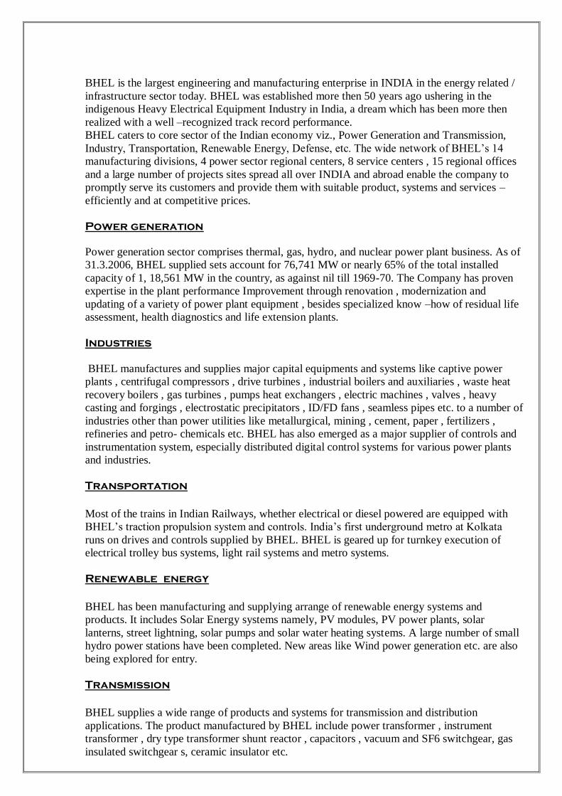
BHEL is the largest engineering and manufacturing enterprise in INDIA in the energy related /
infrastructure sector today. BHEL was established more then 50 years ago ushering in the
indigenous Heavy Electrical Equipment Industry in India, a dream which has been more then
realized with a well –recognized track record performance.
BHEL caters to core sector of the Indian economy viz., Power Generation and Transmission,
Industry, Transportation, Renewable Energy, Defense, etc. The wide network of BHEL’s 14
manufacturing divisions, 4 power sector regional centers, 8 service centers , 15 regional offices
and a large number of projects sites spread all over INDIA and abroad enable the company to
promptly serve its customers and provide them with suitable product, systems and services –
efficiently and at competitive prices.
Power generation
Power generation sector comprises thermal, gas, hydro, and nuclear power plant business. As of
31.3.2006, BHEL supplied sets account for 76,741 MW or nearly 65% of the total installed
capacity of 1, 18,561 MW in the country, as against nil till 1969-70. The Company has proven
expertise in the plant performance Improvement through renovation , modernization and
updating of a variety of power plant equipment , besides specialized know –how of residual life
assessment, health diagnostics and life extension plants.
Industries
BHEL manufactures and supplies major capital equipments and systems like captive power
plants , centrifugal compressors , drive turbines , industrial boilers and auxiliaries , waste heat
recovery boilers , gas turbines , pumps heat exchangers , electric machines , valves , heavy
casting and forgings , electrostatic precipitators , ID/FD fans , seamless pipes etc. to a number of
industries other than power utilities like metallurgical, mining , cement, paper , fertilizers ,
refineries and petro- chemicals etc. BHEL has also emerged as a major supplier of controls and
instrumentation system, especially distributed digital control systems for various power plants
and industries.
Transportation
Most of the trains in Indian Railways, whether electrical or diesel powered are equipped with
BHEL’s traction propulsion system and controls. India’s first underground metro at Kolkata
runs on drives and controls supplied by BHEL. BHEL is geared up for turnkey execution of
electrical trolley bus systems, light rail systems and metro systems.
Renewable energy
BHEL has been manufacturing and supplying arrange of renewable energy systems and
products. It includes Solar Energy systems namely, PV modules, PV power plants, solar
lanterns, street lightning, solar pumps and solar water heating systems. A large number of small
hydro power stations have been completed. New areas like Wind power generation etc. are also
being explored for entry.
Transmission
BHEL supplies a wide range of products and systems for transmission and distribution
applications. The product manufactured by BHEL include power transformer , instrument
transformer , dry type transformer shunt reactor , capacitors , vacuum and SF6 switchgear, gas
insulated switchgear s, ceramic insulator etc.

Technology up gradation, research& development
To remain competitive and meet customer’s expectation, BHEL lays great emphasis on the
continuous up gradation of products and related technologies besides development of new
products. The company has upgraded its products to contemporary levels through continuous in-
house efforts as well as through acquisition of new technologies from leading engineering
organizations of the world.
The company is also engaged in research in futuristic areas like fuel cells for distributed,
environment friendly power generation, clean coal technology applications, super conductivity
application in transformer, motor etc., and nano technology applications for insulators and
membrane filters.
Health , safety and environment management
Harmony between man and environment is the essence of healthy life and growth. Therefore,
maintenance of ecological balance and a pristine environment is of utmost importance to BHEL.
Environment protection continues to be a key area of activity in BHEL along with the growth of
the company.
BHEL is committed to be an environment friendly company in all its area of activities, products,
and services, providing a safe and healthy working environment to all its stakeholders. In fact,
this aspect has become an integral part of the company’s business performance.
INTRODUCTION TO PEM
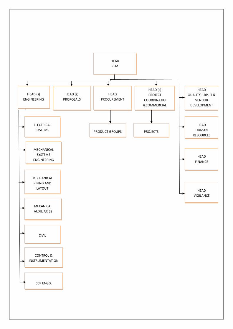
FUNCTIONAL STRUCTURE
HEAD
PEM
HEAD
PROCUREMENT
HEAD (s)
PROJECT
COORDINATIO
&COMMERCIAL
HEAD
QUALITY, LRP, IT &
VENDOR
DEVELOPMENT
PROJECTS PRODUCT GROUPS
ELECTRICAL
SYSTEMS
HEAD (s)
PROPOSALS
HEAD (s)
ENGINEERING
HEAD
HUMAN
RESOURCES
MECHANICAL
SYSTEMS
ENGINEERING HEAD
FINANCE
MECHANICAL
PIPING AND
LAYOUT HEAD
VIGILANCE
MECANICAL
AUXILIARIES
CIVIL
CONTROL &
INSTRUMENTATION
CCP ENGG.
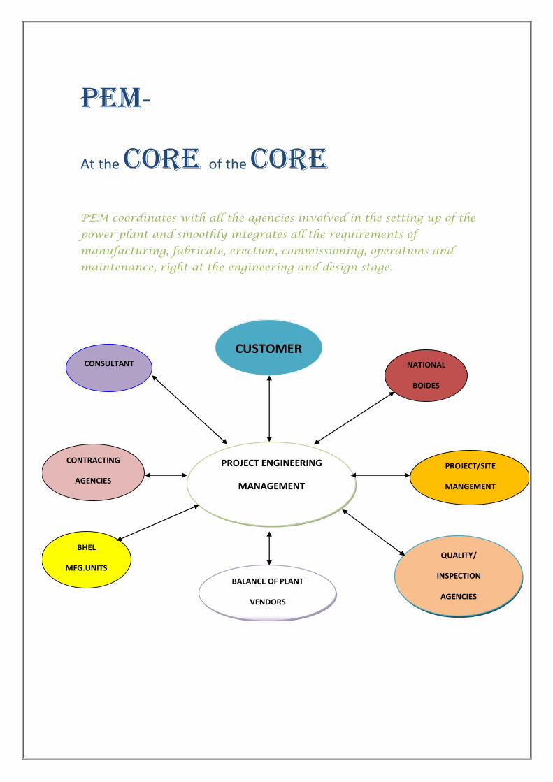
pem-
At the core of the core
PEM coordinates with all the agencies involved in the setting up of the
power plant and smoothly integrates all the requirements of
manufacturing, fabricate, erection, commissioning, operations and
maintenance, right at the engineering and design stage.
PROJECT ENGINEERING
MANAGEMENT
CUSTOMER CONSULTANT NATIONAL
BOIDES
PROJECT/SITE
MANGEMENT
QUALITY/
INSPECTION
AGENCIES
BALANCE OF PLANT
VENDORS
BHEL
MFG.UNITS
CONTRACTING
AGENCIES
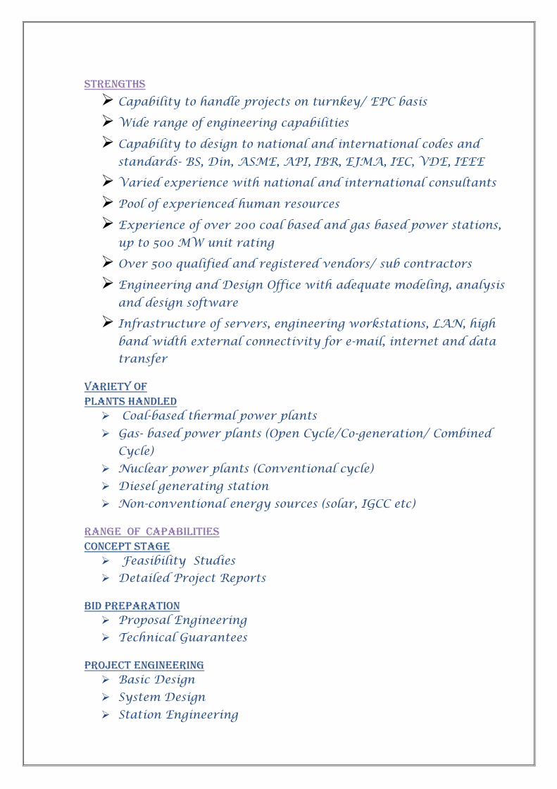
Strengths
Capability to handle projects on turnkey/ EPC basis
Wide range of engineering capabilities
Capability to design to national and international codes and
standards- BS, Din, ASME, API, IBR, EJMA, IEC, VDE, IEEE
Varied experience with national and international consultants
Pool of experienced human resources
Experience of over 200 coal based and gas based power stations,
up to 500 MW unit rating
Over 500 qualified and registered vendors/ sub contractors
Engineering and Design Office with adequate modeling, analysis
and design software
Infrastructure of servers, engineering workstations, LAN, high
band width external connectivity for e-mail, internet and data
transfer
Variety of Plants handled Coal-based thermal power plants
Gas- based power plants (Open Cycle/Co-generation/ Combined
Cycle)
Nuclear power plants (Conventional cycle)
Diesel generating station
Non-conventional energy sources (solar, IGCC etc)
range of capabilities Concept stage Feasibility Studies
Detailed Project Reports
Bid preparation Proposal Engineering
Technical Guarantees
Project engineering Basic Design
System Design
Station Engineering
Development Techno-Economic Studies
Plant Optimization
Technology up-gradation / absorption
Contracts management Project Engineering Coordination
Procurement support Engineering &Procurement of Balance of Plant System
Engineering support To site Erection and commissioning support
Trouble shooting
Renovation, modernization& repowering of power plant electrical systems System design for auxiliary system, Dc system, emergency power, black start power. Power &auxiliary transformers
MV &LV motors
Generator main connections
Generator circuit breaker
MV switchgear
MV &LV bus ducts
LV switchgear/ motor control centers/distribution boards
Control and protection for generator/ transformer
Computer control & instrumentation cables
Dc supply (batteries, chargers, distribution boards)
Lighting
Earthing & lightning protection
Plant communication
Electrical equipment layout
Cabling
Electrical laboratory equipment

Overview of Electrical System
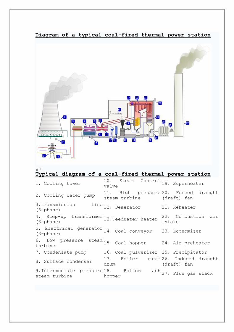
Diagram of a typical coal-fired thermal power station
Typical diagram of a coal-fired thermal power station
1. Cooling tower 10. Steam Control
valve 19. Superheater
2. Cooling water pump 11. High pressure
steam turbine
20. Forced draught
(draft) fan
3.transmission line
(3-phase) 12. Deaerator 21. Reheater
4. Step-up transformer
(3-phase) 13.Feedwater heater
22. Combustion air
intake
5. Electrical generator
(3-phase) 14. Coal conveyor 23. Economiser
6. Low pressure steam
turbine 15. Coal hopper 24. Air preheater
7. Condensate pump 16. Coal pulverizer 25. Precipitator
8. Surface condenser 17. Boiler steam
drum
26. Induced draught
(draft) fan
9.Intermediate pressure
steam turbine
18. Bottom ash
hopper 27. Flue gas stack

ELECTRICAL SYSTEM & EQUIPMENT
The electrical system is designed and engineered to provide a high
degree of reliability, operational flexibility and personnel safety. The
electrical equipment generally conform to Indian Standards and Indian
Electricity Rules.
Various electrical equipment are designed for an ambient temperature of
50 deg C.
ELECTRICAL SYSTEM DESCRIPTION
The Electrical System is shown in `Electrical Single Line Diagram for
Auxiliary Power Distribution' Drg. No. PE-DG-E29-565-E001.
In INDIA, Two Main & Transfer Bus Scheme is more popular although One and a Half
Breaker Scheme is also being adopted.
Plant layouts of 220 kV&400 kV.
1.Two main & transfer bus scheme
a. This scheme is shown in figure-1. In this scheme under normal conditions
incoming & outgoing circuits are normally connected to the main buses in such a
way that due to a bus fault outage of al feeders connected to the faulty bus does
not affect the stability of the system.
b. However, under bus fault conditions, the feeders connected to the faulty bus get
tripped and there is an interruption in the supply.
c. The supply can be restored by transferring all the feeders to the healthy bus,
since both the buses are designed to handle the entire load of the substation.
d. The faulty bus can thus be maintained and brought back in service after
rectification of the fault
e. The planned maintenance of a circuit breaker of any feeder can be carried out
by transferring its load to the bus transfer breaker to transfer bus
f. This is done without interruption of the load.
g. The control and protection signal of the particular feeder circuit are transferred to
the transfer bus breaker.
h. In this scheme, maintenance of one breaker in the substation can be done at a
time.
2.One and a half breaker scheme a. This scheme has been used in a very few substation in INDIA but is very popular
in the U.S.A
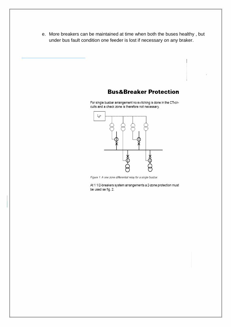
b. This basically employs three breaker for two feeders as shown in figure-2.
c. In this scheme for a bus fault all the breakers connected to the faulty bus get
tripped, but interruption in the supply does not occur since power flow is
maintained though the other bus.
d. Maintenance of one breaker out of three used for two feeders can be done at
any time.
e. More breakers can be maintained at time when both the buses healthy , but
under bus fault condition one feeder is lost if necessary on any braker.

3.Techno-economic analysis
a. Both the scheme have to be analyzed further and their merit and demerits
compared in detail before selecting it for use in the thermal power stations.
System Security
a. FAULT CLEARANCE
It is preferable to trip one breaker for any feeder fault..As such Scheme-1 is better in this respect since two breakers will be required to trip in case of one and half breaker scheme.
The number of feeders lost for a bus bar fault should be as few as
possible.
For scheme-1 there is an interruption till all the affected feeders are
transferred to the health bus.
In scheme-2 continuity of supply is maintained.
b. STUCK BREAKER
This condition Leads to tripping of all the feeders connected to the
particular bus section in case of Scheme-2:
An adjacent feeder trips if the stuck breaker is the middle
breaker
No other feeder is affected if the stuck breaker is the bus side
breaker, even though all the other breakers connected to that
bus also get tripped.
c. REDUNDANCY
In scheme-2 each circuit is fed by two parallel paths i.e. there is
active redundancy or stand-by facilities permanently connected to
the system whereas in Scheme-1 passive redundancy which can be
switched on when required and limited to only one feeder of a
particular bus section at a time is available.
Operational flexibility
a. In Scheme-1, only one breaker is to be operated for switching in or out a feeder.
Secondly, for taking out breaker maintenance, the transfer path through transfer
bus has to be established.
b. In Scheme-2, two breakers are to be operated for bringing a circuit in or taking it
out but for maintenance of a breaker no additional operation is necessary.
Simplicity of protection & control scheme
a. In Scheme-1, the CT‟s have to be switched into the relevant zone of bus bar
protection though the auxiliary contacts of the isolators, which are weak points &
create problems.
b. Secondly, the transfer from main breaker to bypass breaker needs transfer of
closing controls from main breaker to bypass breaker needs transfer of closing
controls from synchronizing and transfer of tripping controls from protection
schemes.
c. In thermal power stations where generator circuit breakers are controlled from
the control desk in the power station the controls of by-pass breaker also need
duplication on the control desk.
d. In Scheme-2, no such provisions are necessary and hence can be considered
more reliable in this respect.
Sectionalizing of buses
a. Both the schemes are capable of being sectionized so as to minimize the
number of circuits affected or the amount of generation lost in the event of a bus
bar fault.
b. Normally outage due to any bus fault shall be limited to the single largest size of
generator connected in the system.
c. However ,detailed system analysis only can determine the exact extent of
sectionalizing to be adopted to maintain system stability.
Maintenance facilities BREAKER MAINTENACE
Both schemes under consideration allow a breaker to be taken out
for planned maintenance without interruption of supply.
The switching sequences, the switching sequence is simple,
comprising tripping of the concerned breaker and opening of the
associated isolators.
For Two Main and Transfer Bus scheme, in addition, the transfer
path has to be established.
ISOLATOR MAITENANCE
In the INDIAN context, isolator maintenance has also to be given
consideration.
Line isolator maintenance needs shutdown of the particular circuit in
both schemes.
For maintenance of bus side isolator in Two Main and Transfer Bus
Scheme there is no interruption in the feeder but the establishing the
transfer path and switching-off the normal breaker.
For One and Half Breaker scheme, there is no loss of feeder but all
the breakers of a particular bus need tripping.
Ease of extension
Both the schemes are capable of being extended.
If future extensions are planned in the initial stages itself, an isolator
in the bus bar run can avoid shutdown when extension is being
carried out.
Land area
In INDIA, generally, availability of land area is not restricted and
hence not a major factor.
However, space reduction due to selection of a particular scheme
can be used for other purposes in the power station.
The area requirement for 220 kV and 400kV switchyards, based on
8 circuits has been worked out and a comparison is given in table -1
It can be seen that area required for scheme-2 is about half in case
of 400 kV and 22okV when compared with scheme-1
Maximum is derived when circuits are arranged back to back to form
a pair.
This arrangement is possible in large generating stations.

Initial cost
Comparisons of cost of typical 8 circuit 220 kV and 400kV substations
for scheme and the scheme 2 is indicated. In this comparison cost of
major equipment, switchyard materials and steel are included. The cost
of civil works and land have not been included since it will vary from
place to place. The cost of cabling and protection equipment has also
not been included.
From this comparison it can be observed that the initial cost of
scheme-2 is about 9% less than the cost of scheme-1 in case
of400kV and 6.75 less in case of 220kV. Since the area requirement
of scheme 2 is less than the scheme -1, the cost of cable trenches,
roads, gravel spreading, illumination equipment, etc, will be less for
scheme -2.
Therefore we can safely assume that the cost for scheme-2 will be les than scheme-1.
Conclusion
The techno-economic analysis done above indicates that one and a half breaker scheme is more favorably placed technically as well as economically when compared to the two main Bus and transfer Bus scheme. As such it is expected that utilities will make more and more use of this scheme in future power stations.
Generator Main Connections System
Typical Coal Fired Power Plant Steam Generator
Each generator is connected to its generator transformer by means of isolated
phase bus ducts. Tap-offs are provided on phase bus ducts for connection to
surge protection & voltage transformer (SP&VT) cubicle and unit transformer
(UT). Isolated bus ducts are also used to form delta connection for low voltage
side of three nos. single phase generator transformers forming the three phase
bank. Generator transformers are sized to evacuate rated MVA of generator.
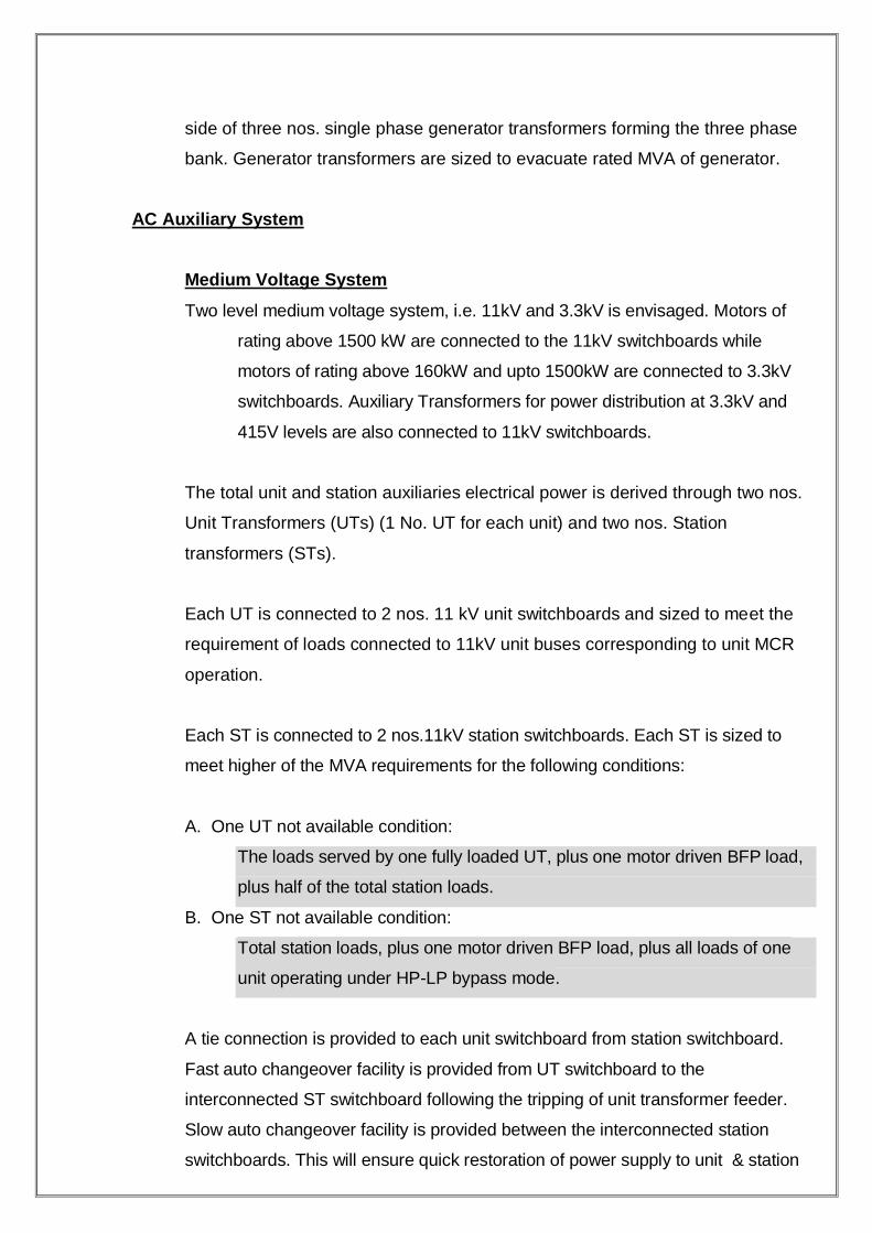
AC Auxiliary System
Medium Voltage System
Two level medium voltage system, i.e. 11kV and 3.3kV is envisaged. Motors of
rating above 1500 kW are connected to the 11kV switchboards while
motors of rating above 160kW and upto 1500kW are connected to 3.3kV
switchboards. Auxiliary Transformers for power distribution at 3.3kV and
415V levels are also connected to 11kV switchboards.
The total unit and station auxiliaries electrical power is derived through two nos.
Unit Transformers (UTs) (1 No. UT for each unit) and two nos. Station
transformers (STs).
Each UT is connected to 2 nos. 11 kV unit switchboards and sized to meet the
requirement of loads connected to 11kV unit buses corresponding to unit MCR
operation.
Each ST is connected to 2 nos.11kV station switchboards. Each ST is sized to
meet higher of the MVA requirements for the following conditions:
A. One UT not available condition:
The loads served by one fully loaded UT, plus one motor driven BFP load,
plus half of the total station loads.
B. One ST not available condition:
Total station loads, plus one motor driven BFP load, plus all loads of one
unit operating under HP-LP bypass mode.
A tie connection is provided to each unit switchboard from station switchboard.
Fast auto changeover facility is provided from UT switchboard to the
interconnected ST switchboard following the tripping of unit transformer feeder.
Slow auto changeover facility is provided between the interconnected station
switchboards. This will ensure quick restoration of power supply to unit & station
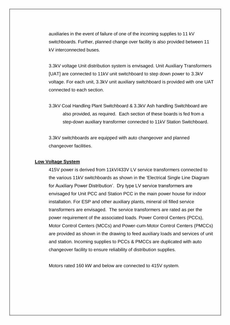
auxiliaries in the event of failure of one of the incoming supplies to 11 kV
switchboards. Further, planned change over facility is also provided between 11
kV interconnected buses.
3.3kV voltage Unit distribution system is envisaged. Unit Auxiliary Transformers
[UAT] are connected to 11kV unit switchboard to step down power to 3.3kV
voltage. For each unit, 3.3kV unit auxiliary switchboard is provided with one UAT
connected to each section.
3.3kV Coal Handling Plant Switchboard & 3.3kV Ash handling Switchboard are
also provided, as required. Each section of these boards is fed from a
step-down auxiliary transformer connected to 11kV Station Switchboard.
3.3kV switchboards are equipped with auto changeover and planned
changeover facilities.
Low Voltage System
415V power is derived from 11kV/433V LV service transformers connected to
the various 11kV switchboards as shown in the 'Electrical Single Line Diagram
for Auxiliary Power Distribution‟. Dry type LV service transformers are
envisaged for Unit PCC and Station PCC in the main power house for indoor
installation. For ESP and other auxiliary plants, mineral oil filled service
transformers are envisaged. The service transformers are rated as per the
power requirement of the associated loads. Power Control Centers (PCCs),
Motor Control Centers (MCCs) and Power-cum-Motor Control Centers (PMCCs)
are provided as shown in the drawing to feed auxiliary loads and services of unit
and station. Incoming supplies to PCCs & PMCCs are duplicated with auto
changeover facility to ensure reliability of distribution supplies.
Motors rated 160 kW and below are connected to 415V system.

Standby Supply System
One number emergency diesel generator set is provided for each unit for safe
shut down of the generating units under normal AC supply failure. The
diesel generator is started automatically from auto-mains failure (AMF)
panel in the event of normal supply failure. A standby DG set common for
both the units is also provided.
DC System
220V DC system is envisaged for unit DC loads such as switchgear, protection,
emergency lighting, DC drives etc. For electronic control & instrumentation,
DC system, as required, is envisaged as part of C&I package.
System Grounding
Grounding philosophy envisaged for the power supply system in the plant is as
follows:
a) Each generator neutral is high resistance grounded by means of neutral
grounding transformer with secondary loading resistor.
b) HV side neutral of generator transformer is solidly grounded.
c) Neutrals of 11kV side of each UT & ST are low resistance grounded, utilising
a grounding resistor and limiting the earth fault current to 300A.
d) 3.3kV system is low resistance grounded at neutrals of 3.3kV side of each
UT, utilising a grounding resistor and limiting the earth fault current to 300A.
e) 415V system is solidly grounded at the 415V neutral of all LV service
transformers. 3 phase, 4 wire system is envisaged for 415V power supply
distribution.
f) 220V DC System is ungrounded.

TURBO GENERATOR
GENERATOR BUSDUCT AND ASSOCIATED EQUIPMENT
Generators are connected by means of isolated phase busduct (IPB) of continuous type between generator line terminals and LV side of generator transformer. Isolated bus ducts are used to form delta connection for low voltage side of three nos. single phase generator transformers forming the three phase bank
Busduct on neutral side is of IPB continuous design up to the star
formation point from where a single neutral duct runs to the neutral
grounding cubicle. An adopter chamber is provided at the generator
terminals to facilitate connections to line and neutral side busducts.
Material for conductor and enclosure is aluminium alloy. Busduct is
supplied in length upto 6-7 meters. It is further reinforced with aluminium
channel rings at intervals, which are also used for enclosure and insulator
mounting. Sealed openings are provided in the busduct run near insulator
for inspection and maintenance. The three phase enclosures are
interconnected effectively at the ends to permit flow of current. Different
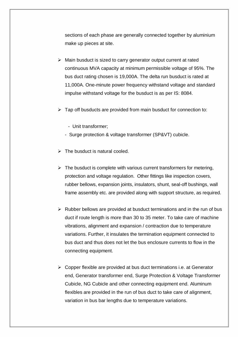
sections of each phase are generally connected together by aluminium
make up pieces at site.
Main busduct is sized to carry generator output current at rated
continuous MVA capacity at minimum permissible voltage of 95%. The
bus duct rating chosen is 19,000A. The delta run busduct is rated at
11,000A. One-minute power frequency withstand voltage and standard
impulse withstand voltage for the busduct is as per IS: 8084.
Tap off busducts are provided from main busduct for connection to:
- Unit transformer;
- Surge protection & voltage transformer (SP&VT) cubicle.
The busduct is natural cooled.
The busduct is complete with various current transformers for metering,
protection and voltage regulation. Other fittings like inspection covers,
rubber bellows, expansion joints, insulators, shunt, seal-off bushings, wall
frame assembly etc. are provided along with support structure, as required.
Rubber bellows are provided at busduct terminations and in the run of bus
duct if route length is more than 30 to 35 meter. To take care of machine
vibrations, alignment and expansion / contraction due to temperature
variations. Further, it insulates the termination equipment connected to
bus duct and thus does not let the bus enclosure currents to flow in the
connecting equipment.
Copper flexible are provided at bus duct terminations i.e. at Generator
end, Generator transformer end, Surge Protection & Voltage Transformer
Cubicle, NG Cubicle and other connecting equipment end. Aluminum
flexibles are provided in the run of bus duct to take care of alignment,
variation in bus bar lengths due to temperature variations.

Epoxy Seal off bushings are provided at Power house wall and at
Generator termination end.
Air pressurization system is envisaged for the bus duct. Air for this
purpose is taken from Station Air system and suitably regulated to the
required pressure [25 – 40 mm of water column] for the bus duct.
The busduct is designed to meet the air tightness and water tightness
requirement specified in IS: 8084.
SP&VT cubicle houses voltage transformers for metering, protection and
voltage regulation, lightning arresters and surge capacitors. Lightning
arresters for generator protection are of station class type. Protective
surge capacitors are non-inflammable synthetic liquid impregnated type,
provided with built-in discharge resistors.
Generator neutral grounding equipment comprises a single phase, dry
type, neutral grounding transformer of rating based on 5 minute duty
cycle. The transformer secondary is loaded with a grounding resistor of
grid type rated for 5 minutes.
TRANSFORMERS
Power Transformers
Power transformers [generator transformers (GT), unit transformers (UT) and
station transformers (ST), unit auxiliary transformers (UAT)] are mineral oil filled,
outdoor design type. The transformers generally conform to IS: 2026.
A] Generator Transformers:
Generator Transformer comprises a bank of three numbers single phase OFAF
cooled transformers. One no. spare single phase generator transformer is also
envisaged, common for the plant. No load voltage ratio of single phase GT is
21 / 420/√3 kV.
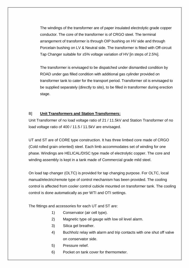
The windings of the transformer are of paper insulated electrolytic grade copper
conductor. The core of the transformer is of CRGO steel. The terminal
arrangement of transformer is through OIP bushing on HV side and through
Porcelain bushing on LV & Neutral side. The transformer is fitted with Off-circuit
Tap Changer suitable for ±5% voltage variation of HV [in steps of 2.5%].
The transformer is envisaged to be dispatched under dismantled condition by
ROAD under gas filled condition with additional gas cylinder provided on
transformer tank to cater for the transport period. Transformer oil is envisaged to
be supplied separately (directly to site), to be filled in transformer during erection
stage.
B] Unit Transformers and Station Transformers:
Unit Transformer of no load voltage ratio of 21 / 11.5kV and Station Transformer of no
load voltage ratio of 400 / 11.5 / 11.5kV are envisaged.
UT and ST are of CORE type construction. It has three limbed core made of CRGO
(Cold rolled grain oriented) steel. Each limb accommodates set of winding for one
phase. Windings are HELICAL/DISC type made of electrolytic copper. The core and
winding assembly is kept in a tank made of Commercial grade mild steel.
On load tap changer (OLTC) is provided for tap changing purpose. For OLTC, local
manual/electric/remote type of control mechanism has been provided. The cooling
control is affected from cooler control cubicle mounted on transformer tank. The cooling
control is done automatically as per WTI and OTI settings.
The fittings and accessories for each UT and ST are:
1) Conservator (air cell type).
2) Magnetic type oil gauge with low oil level alarm.
3) Silica gel breather.
4) Buchholz relay with alarm and trip contacts with one shut off valve
on conservator side.
5) Pressure relief.
6) Pocket on tank cover for thermometer.

7) Oil temperature indicator with maximum pointer and two sets of
contacts.
8) Winding temperature indicator with maximum pointer and two sets
of contacts.(ONAN & OFWF) and 4 sets of contacts (for ONAN/
OFAF and ONAN/ONAF). Repeater dial of winding temperature
indicator for remote indication.
9) VALVES:
a) Oil valve between cooler and main tank.
b) Drain valve
c) 2Nos. filter valves on diagonally opposite corners-size
50mm.
d) 2Nos. sampling valve at top and bottom of main tank.
11) 2Nos. earthling terminals.
12) Rating and diagram plate.
13) Jacking pads.
14) Lifting lugs.
15) Haulage lugs.
16) Cover lifting lugs.
17) Bi-directional flanged rollers with locking and bolting device.
18) Tank mounted weather-proof marshalling box for housing control
equipment and terminal connect.
19) Air release device.
20) Wiring up to marshalling box with PVC SWA PVC copper cables
660/1100 volts grade.
21) COOLING ACCESSORIES [ONAN/ONAF cooling]:
a) Requisite number of radiators with shut-off Valves.
b) Fans.
C] Unit Auxiliary Transformers:
UAT is envisaged with a no load voltage ratio of 11 / 3.5kV.
UAT is of CORE type construction. It has three limbed core made of CRGO
(Cold rolled grain oriented) steel. Each limb accommodates set of winding
for one phase. Windings are HELICAL/DISC type made of electrolytic
copper. The core and winding assembly is kept in a tank made of
Commercial grade mild steel.
Off-circuit tap changer is provided for tap changing purpose. UAT is ONAN
cooled and provided with standard fittings and accessories, generally in
line with those listed for UT above.
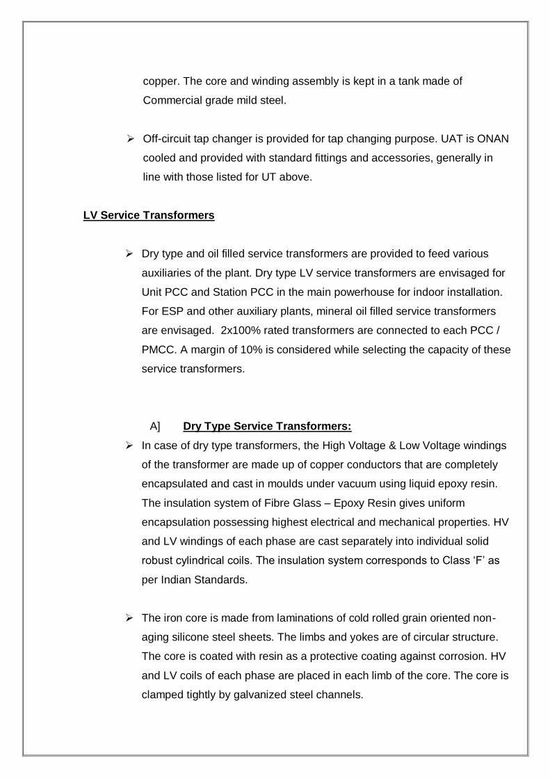
LV Service Transformers
Dry type and oil filled service transformers are provided to feed various
auxiliaries of the plant. Dry type LV service transformers are envisaged for
Unit PCC and Station PCC in the main powerhouse for indoor installation.
For ESP and other auxiliary plants, mineral oil filled service transformers
are envisaged. 2x100% rated transformers are connected to each PCC /
PMCC. A margin of 10% is considered while selecting the capacity of these
service transformers.
A] Dry Type Service Transformers:
In case of dry type transformers, the High Voltage & Low Voltage windings
of the transformer are made up of copper conductors that are completely
encapsulated and cast in moulds under vacuum using liquid epoxy resin.
The insulation system of Fibre Glass – Epoxy Resin gives uniform
encapsulation possessing highest electrical and mechanical properties. HV
and LV windings of each phase are cast separately into individual solid
robust cylindrical coils. The insulation system corresponds to Class „F‟ as
per Indian Standards.
The iron core is made from laminations of cold rolled grain oriented non-
aging silicone steel sheets. The limbs and yokes are of circular structure.
The core is coated with resin as a protective coating against corrosion. HV
and LV coils of each phase are placed in each limb of the core. The core is
clamped tightly by galvanized steel channels.

The transformer (Core-Coil Assembly) is mounted on roller base with plain
bi-directional rollers. Transformer is provided with protective enclosure
made up of HRC steel sheet of protection class IP-23. The control wiring is
terminated on the terminal blocks inside the junction box fitted on
enclosure.
Transformer is provided with following fittings and accessories:
1) For variation of transformation ratio, off circuit tap changer is
provided on HV side. Changing of taps can be done by changing
the tapping links on all the three phases manually.
2) R & D Plate
3) Earthing terminals with lugs
4) Lifting angles
5) Junction Box with wiring
6) Limit Switch
7) Anti Vibration Pad
For thermal protection, temperature monitoring is done by RTD PT-100 sensors
embedded in the coils. These sensors feed signals to temperature scanner
unit for continuous monitoring of winding temperature. The temperature
scanner is provided with auxiliary relays – one for alarm and one for trip.
B] Oil Filled Service Transformers:
Constructional aspects and fittings and accessories for oil filled service
transformers in general are in conformance to `CBIP Manual on
Transformers‟.

MEDIUM VOLTAGE SWITCHGEAR
Following medium voltage Switchboards are provided:
- 4 Nos. 11kV unit switchboards to feed 11kV unit loads
- 4 Nos. 11kV station switchboards to feed 11KV station loads
- 2 Nos. 3.3kV unit auxiliary switchboards to feed 3.3kV motor loads
- 1 No. 3.3kV Coal Handling switchboard
- 1 No. 3.3kV Ash Handling switchboard [if, required]
The switchboards envisaged are of type-tested design. Breakers of
identical rating and design are interchangeable. The switchboards are
provided with "Service/Test/Isolated" position facility for draw out circuit
breakers. The switchboards are complete with standard fittings &
accessories like current transformers, voltage transformers, measuring
instruments, protective/auxiliary/tripping relays, control & selector
switches, indicating lamps, space heaters etc. Interposing relays are
provided for interface with C&I system,
Wherever required. One no. earthing truck for cable end earthing and one
no earthing truck for bus earthing is provided. Earthing trucks are solid
link type.
For motors for Coal Handling Plant, vacuum contactors may be provided
as an alternative to circuit breakers.
Protections envisaged in MV switchgear are as follows:
MV Bus protection
- Time graded over-current protection for all incoming and bus sectionalising
circuits.
- Time graded earth-fault protection for all incoming and bus sectionalising
circuits.

MV motor protection
- Thermal overload protection.
- Instantaneous high set over-current for short-circuit protection
- Instantaneous earth fault protection
- Unbalance current protection
- Locked rotor protection
- Under voltage protection with time delayed tripping under sustained under
voltage
Service transformer protection
- Time graded over-current protection.
- Low voltage winding earth-fault protection
- Buchholz, winding and oil temperature alarm and trip for oil filled transformer
- Winding temperature alarm and trip for dry type transformer.
MEDIUM VOLTAGE SEGREGATED PHASE BUSDUCT
11kV Segregated phase busducts (SPBs) are provided to connect UT and
ST to the respective 11kV Unit and Station Switchboards and also for the
interconnecting ties for these switchboards. 3.3kV SPBs are provided to
connect UATs to the respective sections of 3.3kV Unit Auxilary
Switchboards.
SPB has aluminium conductor and is suitable for indoor/outdoor duty with
natural cooling. Aluminium conductor is supported on epoxy insulators
inside the busduct enclosure. The bus duct enclosure is made of
aluminium alloy sheet. Insulating barriers of 2 mm thick Aluminium sheet
provide complete phase segregation inside the enclosure. The Aluminium
sheet is welded on a framework made up of aluminium angles. Bolted
type inspection covers provide access to the conductor joints and
insulators.
Neoprene bonded cork gaskets are provided between the inspection
covers and the enclosures in order to achieve
fully weather proof duct and airtight construction. The adjacent
enclosures are connected together by means of bolted type flange-to-flange
joints.

Busduct is complete with accessories like rubber bellows, flexibles, seal
off bushings. Space heaters are provided to maintain IR value inside the
bus duct.
Busduct is generally supported from ground in outdoor areas and from
ceiling in indoor areas.
Manual & automatic transfer of loads
The station switchgear shall be provided with manual line changeover
scheme for planned changeover of supply from one incomer to
another and vice versa.
Automatic fast changeover scheme for changeover supply from one
source to another in the event of supply from one source failure from
upstream end shall be provided. Changeover shall be locked if
incomer has tripped due to bus fault.
The closure of the unit supply breaker shall be supervised by a
synchro-check relay permanently connected to nad energized by the
secondary voltages of the unit bus P.T.s. if fast auto change over fails
for whatever reason, an automatic “slow”transfer shall be initiated.
The fast changeover scheme shall be such that the running motors
are not tripped or there is only allowable inrush current due to motor
re-acceleration.
The FBTS should have following transfer modes:
i. FAST TRANSFER
The bus voltage and incoming source voltage should be monitored on
a continuous basis for magnitude and phase angle to ensure that
transfer operation is carried out under conditions conducive to fast bus
transfer as per high speed sync-check supervision.
ii. IN PHASE TRANSFER
The breaker power contacts shall close when the decaying and
drifting bus voltage synchronises with the incoming source voltage
within acceptable voltage and frequency parameters.
The Bus transfer system shall continuously process the bus voltage
and the drifting phase angle dynamics to determine in real-time the

exact moment of sending a command to the breaker-closing coil to
achieve the above.
iii. SLOW TRANSFER
The breaker power contacts shall close when the falling bus voltage
shall reach an acceptable safe value. The auxiliary drives are
selectively tripped simultaneously to limit the transformer inrush
current.
iv. MOMENTARY PARALLELING TRANSFER
This is a “ Make before break “ transfer for a very short duration of the
order of few cycles where, under supervision of the bus voltage and
incoming source voltage for magnitude and phase angle, the new
source breaker is closed before opening the old source breaker.
Normally not recommended for unplanned transfers and auto/
protective transfers from the system safety considerations.
RATINGS OF BREAKERS USED IN THE HT SWITCHGEAR 1. Vacuum circuit breaker (JYOTI) Rated frequency: 50Hz
Rated voltage: 7.2 kV
Rated current: 1250A
Ins. Level: Imp. 75 kVp
PF 28KV
Rated breaking current: 44KA
Rated making current: 110-peak kA
Supply voltage closing: 220DC
Rated short time current: 44KA 3s
Wt. Of breaker: 100Kg
2. Minimum oil circuit breaker (KILOSKAR) Rated frequency: 50Hz
Rated voltage: 6.6 kV
Rated current: 1250A
Breaking capacity: 34.7 kA symmetrical
34.7 kA Asymmetrical
60 MVA symmetrical
Supply voltage closing: 220DC
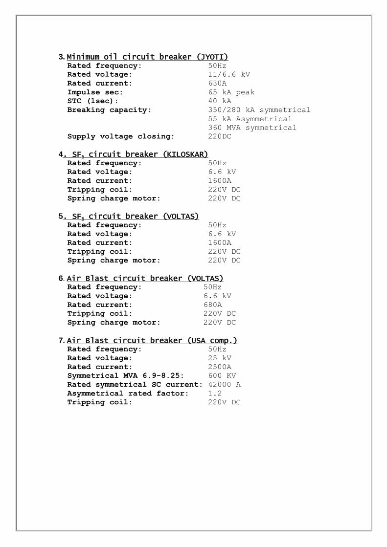
3. Minimum oil circuit breaker (JYOTI) Rated frequency: 50Hz
Rated voltage: 11/6.6 kV
Rated current: 630A
Impulse sec: 65 kA peak
STC (1sec): 40 kA
Breaking capacity: 350/280 kA symmetrical
55 kA Asymmetrical
360 MVA symmetrical
Supply voltage closing: 220DC
4. SF6 circuit breaker (KILOSKAR) Rated frequency: 50Hz
Rated voltage: 6.6 kV
Rated current: 1600A
Tripping coil: 220V DC
Spring charge motor: 220V DC
5. SF6 circuit breaker (VOLTAS) Rated frequency: 50Hz
Rated voltage: 6.6 kV
Rated current: 1600A
Tripping coil: 220V DC
Spring charge motor: 220V DC
6. Air Blast circuit breaker (VOLTAS) Rated frequency: 50Hz
Rated voltage: 6.6 kV
Rated current: 680A
Tripping coil: 220V DC
Spring charge motor: 220V DC
7. Air Blast circuit breaker (USA comp.) Rated frequency: 50Hz
Rated voltage: 25 kV
Rated current: 2500A
Symmetrical MVA 6.9-8.25: 600 KV
Rated symmetrical SC current: 42000 A
Asymmetrical rated factor: 1.2
Tripping coil: 220V DC

PPRROOTTEECCTTIIOONN AANNDD RREELLAAYYSS UUSSEEDD IINN 66..66 KKVV SSWWIITTCCHHGGEEAARR 1. Instantaneous overcurrent relays for short circuit protection
2. Inverse time ground detection relay for zero sequence voltage protection.
3. Under voltage protection.
RATINGS OF OVER CURRENT RELAYS
1. FOR FEEDER AND UNIT BUSES
CT ratio: 600/5A
RMA: 18A
RT: 0.5 sec
2. FOR STATION BUSES
CT ratio: 2000/5/1A
RMA: 15A
RT: 1.5 sec
3. FOR RESERVE SUPPLY
CT ratio: 1000/5/1A
RMA: 14A
RT: 1.0 sec
4. FOR COOLING TOWERS
CT ratio: 400/5/1A
RMA: 16A
RT: 1.0 sec
5. FOR XMERS (SAY TRANSFORMER NO. 1(630 KVA))
CT ratio: 100/5/1A
RMA: 14A
RT: 0.5 sec
Rest Xmers have almost similar relay ratings
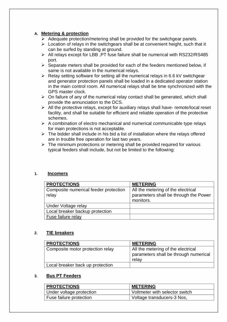
A. Metering & protection
Adequate protection/metering shall be provided for the switchgear panels. Location of relays in the switchgears shall be at convenient height, such that it
can be surfed by standing at ground. All relays except for LBB ,PT fuse failure shall be numerical with RS232/RS485
port. Separate meters shall be provided for each of the feeders mentioned below, if
same is not available in the numerical relays. Relay setting software for setting all the numerical relays in 6.6 kV switchgear
and generator protection panels shall be loaded in a dedicated operator station in the main control room. All numerical relays shall be time synchronized with the GPS master clock.
On failure of any of the numerical relay contact shall be generated, which shall provide the annunciation to the DCS.
All the protective relays, except for auxiliary relays shall have- remote/local reset facility, and shall be suitable for efficient and reliable operation of the protective schemes.
A combination of electro mechanical and numerical communicable type relays for main protections is not acceptable.
The bidder shall include in his bid a list of installation where the relays offered are in trouble free operation for last two years.
The minimum protections or metering shall be provided required for various typical feeders shall include, but not be limited to the following:
1. Incomers
PROTECTIONS METERING
Composite numerical feeder protection relay
All the metering of the electrical parameters shall be through the Power monitors.
Under Voltage relay
Local breaker backup protection
Fuse failure relay
2. TIE breakers
PROTECTIONS METERING
Composite motor protection relay
All the metering of the electrical parameters shall be through numerical relay
Local breaker back up protection
3. Bus PT Feeders
PROTECTIONS METERING
Under voltage protection Voltmeter with selector switch
Fuse failure protection Voltage transducers-3 Nos,
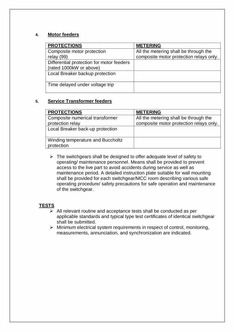
4. Motor feeders
PROTECTIONS METERING
Composite motor protection relay (99)
All the metering shall be through the composite motor protection relays only.
Differential protection for motor feeders (rated 1000kW or above)
Local Breaker backup protection
Time delayed under voltage trip
5. Service Transformer feeders
PROTECTIONS METERING
Composite numerical transformer protection relay
All the metering shall be through the composite motor protection relays only.
Local Breaker back-up protection
Winding temperature and Buccholtz protection
The switchgears shall be designed to offer adequate level of safety to
operating/ maintenance personnel. Means shall be provided to prevent access to the live part to avoid accidents during service as well as maintenance period. A detailed instruction plate suitable for wall mounting shall be provided for each switchgear/MCC room describing various safe operating procedure/ safety precautions for safe operation and maintenance of the switchgear.
TESTS
All relevant routine and acceptance tests shall be conducted as per applicable standards and typical type test certificates of identical switchgear shall be submitted.
Minimum electrical system requirements in respect of control, monitoring, measurements, annunciation, and synchronization are indicated.
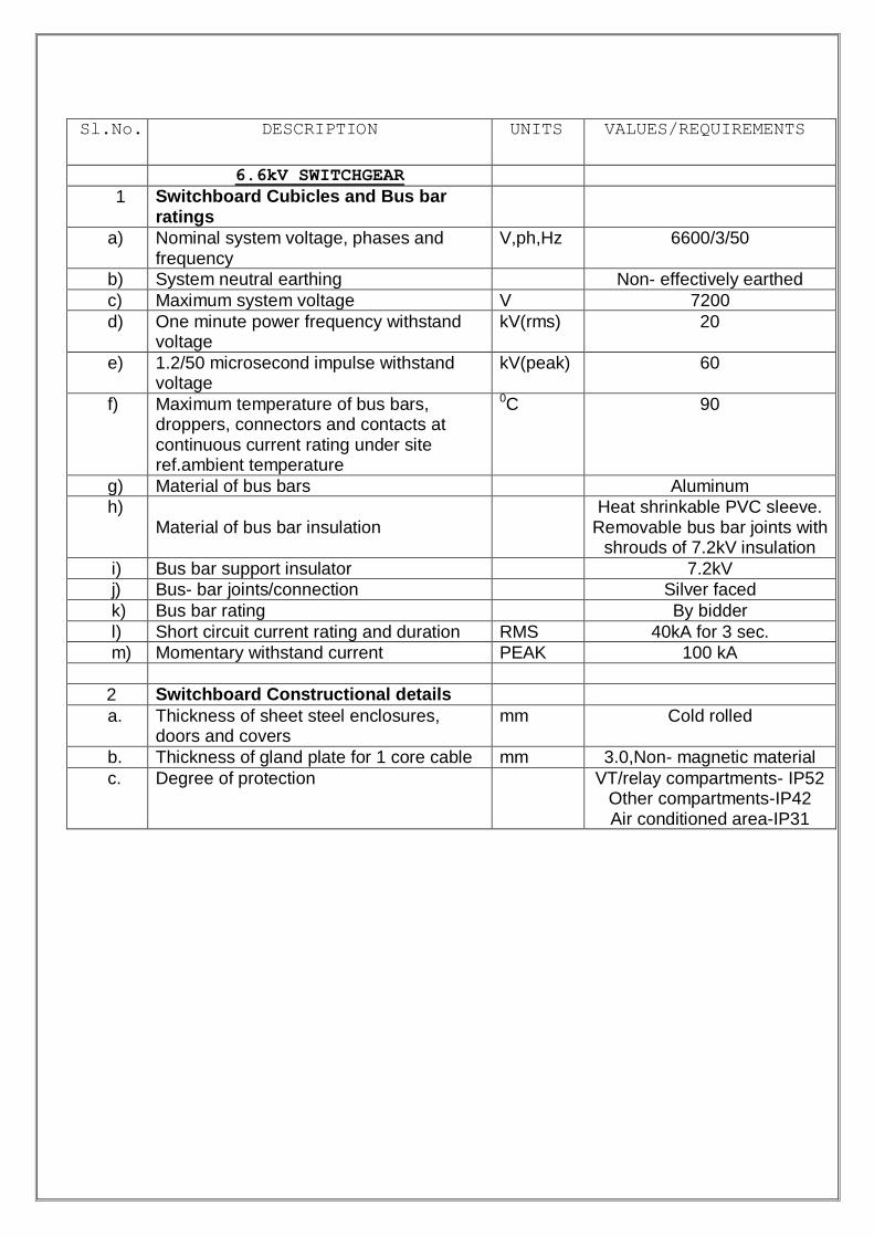
Sl.No. DESCRIPTION UNITS VALUES/REQUIREMENTS
6.6kV SWITCHGEAR
1 Switchboard Cubicles and Bus bar ratings
a) Nominal system voltage, phases and frequency
V,ph,Hz 6600/3/50
b) System neutral earthing Non- effectively earthed
c) Maximum system voltage V 7200
d) One minute power frequency withstand voltage
kV(rms) 20
e) 1.2/50 microsecond impulse withstand voltage
kV(peak) 60
f) Maximum temperature of bus bars, droppers, connectors and contacts at continuous current rating under site ref.ambient temperature
0C 90
g) Material of bus bars Aluminum
h) Material of bus bar insulation
Heat shrinkable PVC sleeve. Removable bus bar joints with
shrouds of 7.2kV insulation
i) Bus bar support insulator 7.2kV
j) Bus- bar joints/connection Silver faced
k) Bus bar rating By bidder
l) Short circuit current rating and duration RMS 40kA for 3 sec.
m) Momentary withstand current PEAK 100 kA
2 Switchboard Constructional details
a. Thickness of sheet steel enclosures, doors and covers
mm Cold rolled
b. Thickness of gland plate for 1 core cable mm 3.0,Non- magnetic material
c. Degree of protection VT/relay compartments- IP52 Other compartments-IP42 Air conditioned area-IP31

LOW VOLTAGE SWITCHGEAR SCOPE
If we talk in simple language switchgear is one which makes or breaks on electric circuit.
This definition straight away does not attract much curiosity nor does it show any linking of the enormous consideration required in designing switchgear.
Numerous problems encountered in errection, testing and commissioning of the switchgear and various precaution are to be taken in operation and maintenance of the switchgear.
This report describes the various types of switchgear and their usage.
Low voltage switchgear comprises of 415V Power Control Centers (PCCs),
415V Motor Control Centers (MCCs), 415V Power cum Motor Control Centers
(PMCCs), 415V/240V AC Distribution Board (ACDBs) and Local Control
Centres (LCCs). PCCs & PMCCs are for Auxiliary Power Distribution. Low
voltage switchgear conforms generally to Indian Standard IS: 13947.
General Constructional Features All frames and load bearing members are fabricated using mild steel
structural sections or pressed and shaped cold rolled sheet steel of
thickness not less than 2 mm. Frame is enclosed in cold rolled sheet steel
of thickness not less than 1.6mm. Doors and covers are also of cold rolled
sheet steel of thickness not less than 1.6mm. Stiffners are provided
wherever necessary.
All switchboards/ panels are dust and vermin proof. All cutouts have synthetic
rubber gaskets.
All switchboards, MCCs and DBs have following distinct vertical sections:
1 Completely enclosed busbar compartment for horizontal and vertical
busbars.
2 Completely enclosed switchgear compartments, one for each breaker, motor
starter or switchfuse unit.
3 Compartment, alley or cable box for power and control cables.
4 Compartment for relays and other control devices associated with a circuit
breaker, wherever necessary.
MCCs and DBs are divided into vertical sections. Each vertical section is
provided with adequately sized cable alley covering entire height. In case
cable alleys are not provided for DBs, segregated cable boxes with
complete shrouding for individual feeders are provided at the rear for
direct termination of cables in each individual feeder.
Busbars are of high conductivity aluminium alloy. Minimum air clearance in
air between phases and phase-earth is 25mm. For all other components,
the clearances is at least 10mm. Wherever above is not possible except for
horizontal and vertical busbars, insulation is provided by sleeving or
barriers. In case of DCDBs/fuse boards, the busbar system is insulated or
physically segregated with barriers to prevent interpole short circuit.
Busbars insulators are of track-resistant, high strength, non-hygroscopic,
non-combustible type and suitable to withstand stresses due to over-
voltages and short circuit current.
All non-current carrying metal work of boards/panels is effectively bonded
to earth bus of galvanized steel, extending throughout the
switchboard/MCC/DB. Positive earthing is maintained for all positions of
chassis and breaker frame.
The maximum temperature rise of the horizontal and vertical busbars and
main bus link including all power drawout contacts when carrying 90% of
the rated current along the full run is 55deg.C with silver plated joints and
40deg.C with all other types of joints over an ambient of 50deg.C.

415V Power Control Centers (PCCs)
The switchboards are single front draw out type and compartmentalized to
accommodate circuit breakers in single tier or double tier. The switchboard
has a short circuit rating of 50kA rms for 1 sec. All switchboards up to 1600A
rating conform to DOP IP: 52, while the switchboards rated above 1600A are
provided with louvers and conform to DOP IP: 42. The outgoing feeders rated
630A and above are provided with ACBs. Switch fuse units are provided for
rating up to 400A. The circuit breakers are triple pole, air break, horizontally
draw out type having 'test/service/isolated' positions. The circuit breakers are
electrically operated having motor wound, spring charged stored energy
mechanism. The control voltage of circuit breakers is 220V DC.
Metering, protection and control equipment like ammeter, voltmeter, relays,
control and selector switch etc. are housed in the switchboard. Interlocks, auto
changeover between incomers and bus coupler breaker are provided as per
requirement. Feeder protections comprising over current and earth fault relays
are provided. Alternatively, circuit breakers may have built–in releases for the
same purpose. Breaker controlled starters for motors are generally connected
directly to PCC and provided with short circuit, overload and earth-fault
protection. Interposing relays for interface with C&I systems are provided,
wherever required. Cable gladding and termination arrangement is envisaged
at the rear side of the ACB panels.

415V Motor Control Centers (MCCs)
Required numbers of motor control centres are provided for the power
plant and these are located near the respective loads/plants.
Motor control centres are drawout type, double front, with degree of protection IP:52.
MCCs rated above 400A have air-circuit breakers as incomers. For
ratings up to 400A, load switches are provided. Outgoing supply feeders
of rating 400A and below are equipped with switch fuse units. MCCs fed
by circuit breakers have a short circuit rating of 50kA rms for 1 sec.
whereas MCCs fed by switch fuse units have a short circuit rating of 50kA
for 0.2 secs.
Motors rated upto125kW are provided with bi-metallic relays for thermal
overload protection and HRC fuses for short circuit protection. Motors
rated above125kW (upto160kW) are provided with locked rotor protection
in addition to above. Motor starters are direct-on-line type.

Motor starter schemes have provision for 240V supply for space heating
for motors rated above 30kW.
Interposing relays for interface with C&I system are provided, wherever
required.
Two common control transformers of ratio 415/110V and adequate rating
(one on each section of MCC) are provided in each motor control centre
for the purpose of control supply to all starters in that MCC. Each section
of MCC is provided with bus voltage module comprising of fuse and
voltmeter with selector switch. An ammeter is provided for motors rated
above 30 kW. For drives requiring ammeter on remote control
equipment, transducer is provided in the MCC.
415V Power cum Motor Control Centers (PMCC)
For load centres where the associated loads/plant are located in the vicinity of
the auxiliary transformer, power control centres and motor control centres are
made common to form a PMCC having features described above for PCC and
MCC and are in double front execution.
AC Distribution Boards (ACDBs)
AC distribution boards are provided for three phase and single phase power
distribution. The DBs are fixed type and floor mounted. Switchfuse outlets are
provided, as required.
Local Control Stations & Local Starters
Local control stations are provided near the unidirectional motors for emergency `stop'. These local control stations conform to degree of protection of IP: 54 for indoor and IP: 55 for outdoor.
Local push button stations have metal enclosure of die cast aluminium or
rolled sheet steel of 1.6mm thickness.
Local starters may be provided for exhaust fans, sump pumps etc., as per
requirements of the layout.

LV Busduct
Metal enclosed, natural air cooled, non-segregated phase busducts
(NSPBs) are provided for Interconnection between LV Service
transformers and LV switchgear.
The busduct has aluminium conductor and is suitable for indoor/outdoor
duty with natural cooling.
Conductors and inside surface of enclosures are treated with mat black
paint for efficient heat dissipation.
Bimetallic connectors are provided in case equipment terminals and
material of bus conductor are different.
Bolted and flexible joints for conductor and enclosure are provided at all
equipment terminations.
Busduct is generally supported from ground in outdoor areas and from
ceiling in indoor areas.
SECONDARY WIRING AND TERMINALS
a. All internal wiring for connections to remote equipment shall run to terminal boards. Spare auxiliary switches, contacts or relay contacts shall also be wired up to terminal board as per schemes. Wires shall not be jointed or teed-off between terminal points.
b. Wiring shall be made by 1100-volt grade seven strands PVC insulated copper wire
having a cross-sectional area of not less than 1.5 sq.mm. All connections from CT leads upto instruments, relays, terminal board shall be made by copper wires of minimum 2.5 sq.mm size. The cables shall be tested for flammability test as per applicable standards and shall also withstand service temperature without deterioration.
c. All wiring shall be made with the Colour Codes specified below:
a) 3 phase AC Connections Phase 1 (R) Red Phase 2 (Y) Yellow Phase 3 (B) Blue
b) 1 phase AC Connections Phase Red Neutral Black
c) DC Connections
Positive Red Negative Blue Neutral Black
d) Earth Connection Green

NOTE: 1. Colour of outer sheath of AC and DC wiring shall be grey. However for
DC control wiring, white colour of outer sheath is also acceptable.
2. Where the single-phase conductors are associated with the 3-phase system from which they are derived, the phase conductor shall use the same colour as that phase from which it is derived.
d. Where wiring is subjected to movement, flexible wires having not less than 40
strands, with a minimum cross-sectional area of 2.5 sq. mm. of conductors, shall be used.
e. Wiring shall be run mostly clear of all metal parts in insulated cleats & shall be
properly routed, neatly bunched. However, PVC wire holders and channels shall be preferred for running of wiring.
f. Where wiring passes from one compartment to another, the aperture shall be
„Bushed‟ to prevent damage of wires against sheet metal edges. Bushes may comprise of good quality rubber grommets.
g. Intermodule bus wires shall be kept separate from all other wiring. AC or DC
terminations shall be grouped function-wise as far as possible and labels of the function shall be affixed.
h. Every wire end for interpanel termination shall be fitted with numbered ferrules of
white or yellow colour having glossy finish with identification number engraved in black. Ferrules shall be made of moisture and oil resisting insulating material. Ferrules shall be of interlocked type or tight fitting type. Ferrules shall be so fitted that they will not get detached, when the wire is removed from the terminal.
i. System of marking of wiring shall be as per applicable standard.
j. All wires used internally shall have crimped on tinned copper lugs for terminations.
k. Terminal boards shall be either of stud or pressure screw or insertion type.
l. Insulating barriers of adequate height shall be provided between adjacent pairs of
terminals unless the terminal board moulding inherently provides a barrier between pair of terminals.
m. Transparent front covers shall be provided if the terminals are not finger proof.
Terminals shall have marking for terminal identification.
n. Terminal boards shall have separate terminals for incoming and outgoing wires with not more than two wires connected to any one terminal. Terminal boards shall have separate terminals for incoming and outgoing
wires with not more than two wires connected to any one terminal. o. Terminal boards shall be mounted vertically at the side of the cubicle or in the
horizontal rows and properly spaced to have clean wiring arrangement, adequate access for putting ferrules, making terminations etc.
p. It shall be possible to read the ferrule numbers when the wiring is complete. Where terminals may be live when the equipment is isolated from the main supply, these shall be clearly marked on the panel.
q. Spare terminals to the extent of twenty percent of the used terminals shall be
provided for each module. CONTROLS, INDICATIONS & ALARMS a. The controls, indications and alarms shall be provided as per enclosed schemes.
b. The location of control for switchgear shall be either the control room, local to the
equipment controlled, on the switchgear or in any combination of these as per typical schemes enclosed with Section-C. Control-Selector-Switch shall be provided accordingly.
c. All switchgear comprising of withdrawable units shall have test feature, where
specified in Data Sheet A, for operation check-up purposes. This will allow manual and/or electrical closing and tripping of switchgear with power connection disconnected both at the bus and circuit ends. In the TEST position, all incoming & outgoing remote electrical controls and interlocks shall not cause the switchgear equipment to be operated manually or otherwise.
d. Means for simulation testing shall be provided, where called for in Data Sheet A.
e. Circuit breaker control switches shall be operated in clockwise direction for closing
the circuit breaker and anti-clockwise for opening (tripping) and shall automatically return to the neutral (mid-position).
f. The alarm bell in alarm circuits shall be suitable for the duty imposed on it by the
ringing cycle as per scheme.
SWITCHGEAR MAIN ASSEMBLIES
AIR CIRCUIT BREAKERS
General Requirements
a. Circuit breaker units shall be of air-break, metal enclosed horizontal withdraw able type having short circuit ratings.
b. Moving portion of each circuit breaker unit shall consist of 3 or 4 poles, with
common operating mechanism, primary and secondary disconnecting (isolating) devices, auxiliary switches, mechanical position indicator and necessary wiring all mounted on a robust steel frame work.
c. Primary and secondary disconnecting devices shall be robust, reliable, fully
self-isolating and self-aligning. These shall comprise of silver plated copper
contacts. It is preferred to have a design with the secondary disconnecting devices located on the side of the circuit breaker.
d. All the secondary disconnecting devices shall make both in SERVICE & TEST
position of the circuit breakers, unless specified for programmable type functions and called for in Data Sheet A.
e. Secondary disconnecting device comprising of single multiway plug & socket is
also acceptable provided the interlocking requirements as specified in clause 4.1.6 are fulfilled.
f. Circuit breakers of same current rating shall be fully inter changeable with one
another. The design shall prevent circuit breakers from being taken into TEST and SERVICE positions of fixed housing of breakers of different ratings. The arrangement shall be such as to prevent damage to isolating contacts.
g. Positively driven auxiliary switches shall be provided for indication, control &
interlocking. These shall comprise of a minimum 6NO + 6NC contacts in addition to those required for internal use. These shall be wired up to the secondary isolating devices. Where the specified number of auxiliary contacts is not available, the same shall be derived through suitable contact multiplication.
h. It shall be possible to draw in or out the breaker to SERVICE, TEST &
ISOLATED position without opening the cubicle door. It shall be possible to close the door even when circuit breaker is drawn out to ISOLATED or TEST position, thus preventing entry of vermin & dust.
i. It shall be possible to manually charge the closing spring and close/trip the breaker without opening door. Access to the device affecting these shall be possible even with compartment door closed.
j. The circuit breaker shall be provided with the following set of positively driven
mechanical position indicators available on the door front.
Breaker ON/OFF Breaker SERVICE/TEST/ISOLATED Breaker closing spring CHARGED/DISCHARGED
The mechanism shall be such that failure of auxiliary spring shall not prevent tripping and also not cause tripping of closed circuit breaker.

Operating Mechanism
a. The operating mechanism shall be strong, positive & fast in operation.
b. The circuit breaker mechanism shall preferably be of motor wound charged spring assisted & of trip free design i.e. the trip command always predominating closing command. Where required, manually operated circuit breakers provided with manual spring charged stored energy closing mechanism shall be offered.
c. Circuit breaker operation shall be independent of the motor, which shall be
solely for the charging of the spring. d. Motor wound charged spring mechanism shall be provided with electrical
release coil.
e. The mechanism shall preferably be such that:
If the circuit breaker is open and the springs charged, the circuit breaker can be closed & tripped.
If the circuit breaker is closed and the springs charged, there shall be
sufficient energy to trip, close & then trip.
f. Circuit breaker operating mechanism shall be fitted with an electrical shunt trip coil in addition to mechanically operated hand-tripping device. The electrical tripping and closing devices shall be suitable for operating from Electrical (AC/DC) supplies as specified under Data Sheet A. The devices shall operate satisfactorily at their rated operating temperature over the following range of voltage variation:
Spring charging motor 85 to 110% Closing release coil 85 to 110% Shunt trip coil 70 to 110%
g. All operating coils for use in DC supply shall be connected such that failure of
insulation to earth does not cause the coil to be energised.
h. Tripping & closing circuits shall be provided with fuse or miniature circuit breaker in each pole on each unit and shall be independent of each other and all other circuits.
i. Locking facilities shall be provided to prevent the closing of circuit breaker
when it is open and from being manually tripped when it is closed. In case it is not possible to provide locking facility to prevent manual tripping suitable shroud or flap shall be provided on the manual trip actuator to prevent its inadvertent operation.
j. Provision shall be made to ensure that when manual-operating mechanism for
maintenance purpose is being used, it shall not be possible to electrically close the breaker.
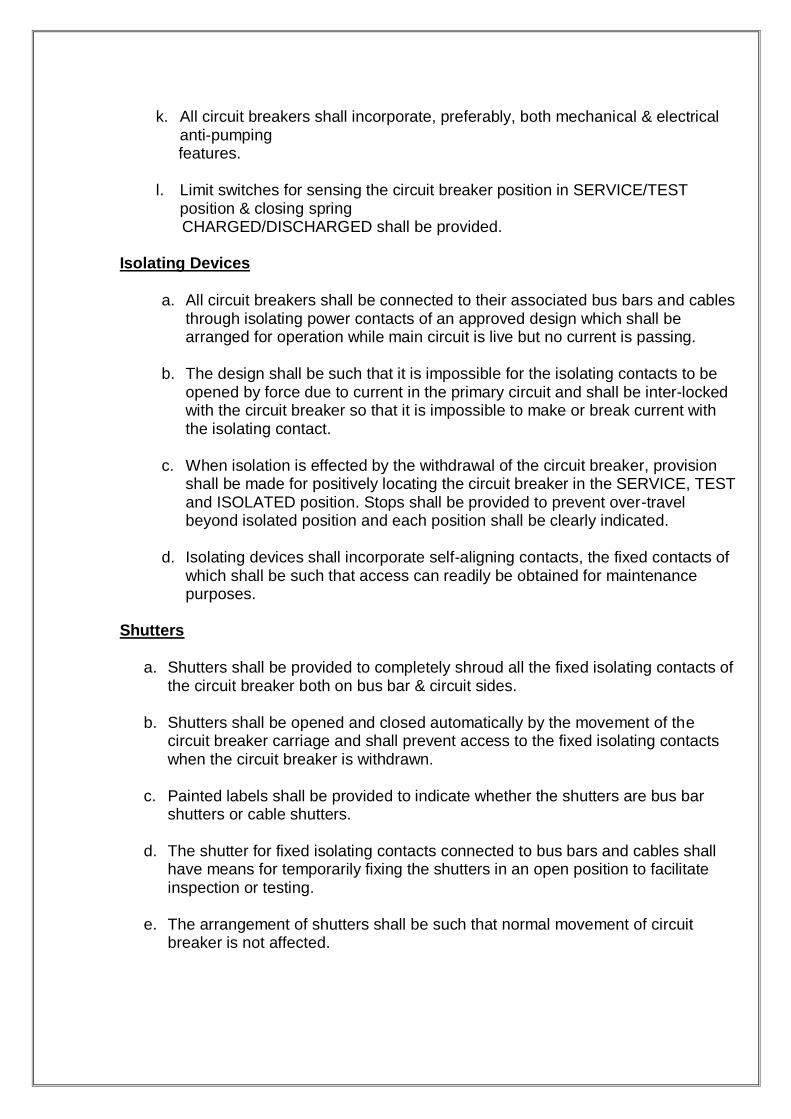
k. All circuit breakers shall incorporate, preferably, both mechanical & electrical anti-pumping features.
l. Limit switches for sensing the circuit breaker position in SERVICE/TEST
position & closing spring CHARGED/DISCHARGED shall be provided. Isolating Devices
a. All circuit breakers shall be connected to their associated bus bars and cables
through isolating power contacts of an approved design which shall be arranged for operation while main circuit is live but no current is passing.
b. The design shall be such that it is impossible for the isolating contacts to be
opened by force due to current in the primary circuit and shall be inter-locked with the circuit breaker so that it is impossible to make or break current with the isolating contact.
c. When isolation is effected by the withdrawal of the circuit breaker, provision
shall be made for positively locating the circuit breaker in the SERVICE, TEST and ISOLATED position. Stops shall be provided to prevent over-travel beyond isolated position and each position shall be clearly indicated.
d. Isolating devices shall incorporate self-aligning contacts, the fixed contacts of
which shall be such that access can readily be obtained for maintenance purposes.
Shutters
a. Shutters shall be provided to completely shroud all the fixed isolating contacts of
the circuit breaker both on bus bar & circuit sides.
b. Shutters shall be opened and closed automatically by the movement of the circuit breaker carriage and shall prevent access to the fixed isolating contacts when the circuit breaker is withdrawn.
c. Painted labels shall be provided to indicate whether the shutters are bus bar
shutters or cable shutters.
d. The shutter for fixed isolating contacts connected to bus bars and cables shall have means for temporarily fixing the shutters in an open position to facilitate inspection or testing.
e. The arrangement of shutters shall be such that normal movement of circuit
breaker is not affected.
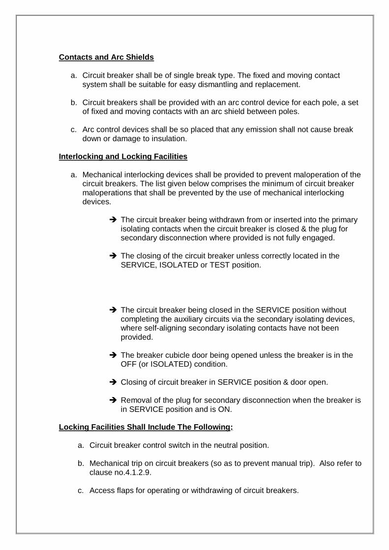
Contacts and Arc Shields
a. Circuit breaker shall be of single break type. The fixed and moving contact system shall be suitable for easy dismantling and replacement.
b. Circuit breakers shall be provided with an arc control device for each pole, a set
of fixed and moving contacts with an arc shield between poles.
c. Arc control devices shall be so placed that any emission shall not cause break down or damage to insulation.
Interlocking and Locking Facilities
a. Mechanical interlocking devices shall be provided to prevent maloperation of the circuit breakers. The list given below comprises the minimum of circuit breaker maloperations that shall be prevented by the use of mechanical interlocking devices.
The circuit breaker being withdrawn from or inserted into the primary
isolating contacts when the circuit breaker is closed & the plug for secondary disconnection where provided is not fully engaged.
The closing of the circuit breaker unless correctly located in the
SERVICE, ISOLATED or TEST position.
The circuit breaker being closed in the SERVICE position without completing the auxiliary circuits via the secondary isolating devices, where self-aligning secondary isolating contacts have not been provided.
The breaker cubicle door being opened unless the breaker is in the
OFF (or ISOLATED) condition.
Closing of circuit breaker in SERVICE position & door open.
Removal of the plug for secondary disconnection when the breaker is in SERVICE position and is ON.
Locking Facilities Shall Include The Following:
a. Circuit breaker control switch in the neutral position.
b. Mechanical trip on circuit breakers (so as to prevent manual trip). Also refer to clause no.4.1.2.9.
c. Access flaps for operating or withdrawing of circuit breakers.
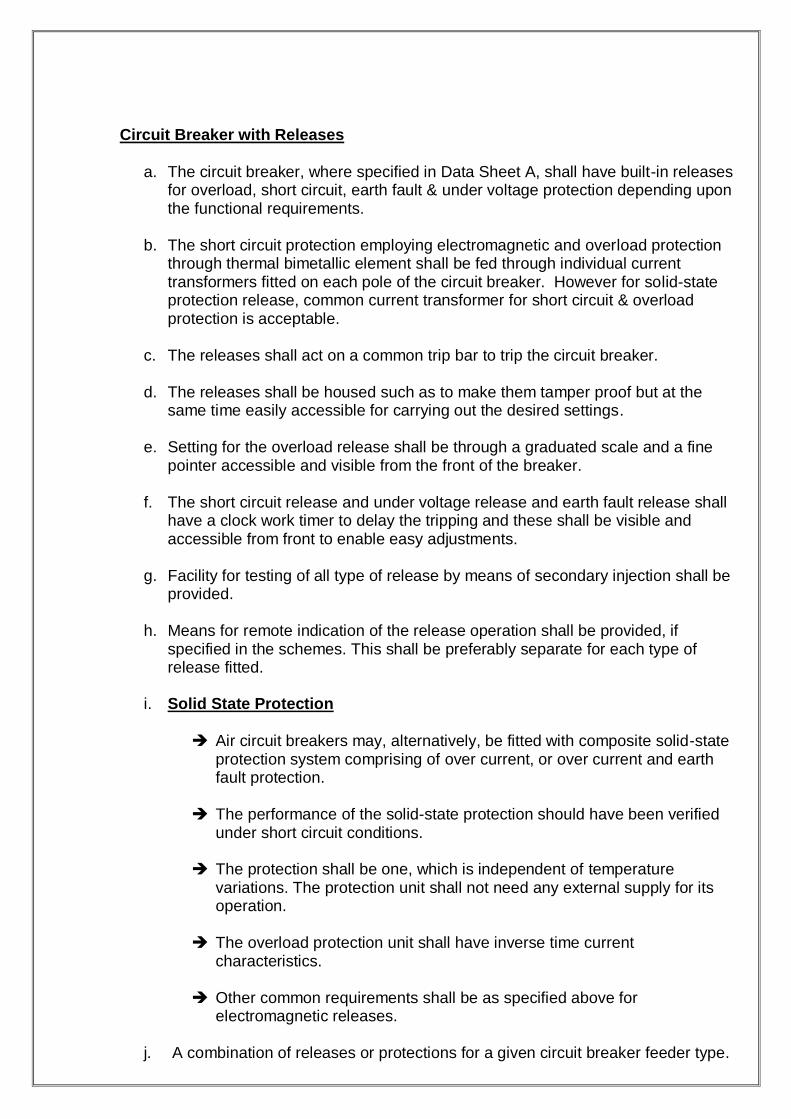
Circuit Breaker with Releases
a. The circuit breaker, where specified in Data Sheet A, shall have built-in releases for overload, short circuit, earth fault & under voltage protection depending upon the functional requirements.
b. The short circuit protection employing electromagnetic and overload protection
through thermal bimetallic element shall be fed through individual current transformers fitted on each pole of the circuit breaker. However for solid-state protection release, common current transformer for short circuit & overload protection is acceptable.
c. The releases shall act on a common trip bar to trip the circuit breaker.
d. The releases shall be housed such as to make them tamper proof but at the
same time easily accessible for carrying out the desired settings.
e. Setting for the overload release shall be through a graduated scale and a fine pointer accessible and visible from the front of the breaker.
f. The short circuit release and under voltage release and earth fault release shall
have a clock work timer to delay the tripping and these shall be visible and accessible from front to enable easy adjustments.
g. Facility for testing of all type of release by means of secondary injection shall be
provided.
h. Means for remote indication of the release operation shall be provided, if specified in the schemes. This shall be preferably separate for each type of release fitted.
i. Solid State Protection
Air circuit breakers may, alternatively, be fitted with composite solid-state
protection system comprising of over current, or over current and earth fault protection.
The performance of the solid-state protection should have been verified
under short circuit conditions.
The protection shall be one, which is independent of temperature variations. The protection unit shall not need any external supply for its operation.
The overload protection unit shall have inverse time current
characteristics.
Other common requirements shall be as specified above for electromagnetic releases.
j. A combination of releases or protections for a given circuit breaker feeder type.

VIII Operating Conditions
a. Breakers controlling motors shall operate satisfactorily under the following conditions:
Direct-on-line starting of induction motors rated above 160 kW with a
locked rotor current of seven times the rated current and starting time up to 30 seconds.
Breaking no load, full load and locked rotor current of induction motors as
stated above. IX CONTACTOR STARTER UNITS
a. All motors upto and including 160 kW shall be controlled by Direct-on-line
contactor starters, a combination of following: Isolating device;
Contactor as main means of starting and stopping of motor;
A short circuit protective device (SCPD);
Thermal overload protection with built in single phasing prevention feature;
Locked rotor protection, if specified in Data Sheet A.
b. Hardware to achieve any given type of function shall be as per enclosed
schemes.
c. Withdraw able contactor starter units shall be provided with means for mechanically indicating the SERVICE and other positions of trolley.
d. The starter units shall carry designation labels in terms of module type codes,
signifying the function of the unit. Labels indicating these shall be affixed on fixed and withdraw able portion of the unit.
e. The units shall be designed to ensure safety of operating personnel.
f. Interlocks shall be provided to ensure that the unit access door can only be
opened when the associated isolating device is open. Defeat interlock facility shall be provided.
g. The selection of rating of power component and the coordination with protective
devices shall be done based on motor rating and characteristics. The type of co-ordination required shall be as specified in Data Sheet A in accordance with applicable standard.
h. Components of the contactor starter units shall meet the stipulations under
clause 5.0.

SWITCH FUSE UNITS
a. These units shall preferably comprise of switches having integral fuses, called
composite units. Alternatively, combination units of separate switch and fuse may also be acceptable.
b. These units shall be provided for general purpose i.e. incoming or outgoing units
on switchgear.
c. The units shall be of the air break air insulated type, and designed to ensure safety to operating personnel.
d. Composite units shall have integral fuses. The design shall ensure that the
moving contact is not live when switch is open i.e. in OFF position, so as to facilitate removal of fuse.
e. The switch shall be capable of breaking 3 times the normal rated current at 0.3
power factor and 110% rated voltage, and making and carrying the system prospective fault current, but limited in magnitude and duration by the cut off characteristics of the largest HRC fuse link that may be fitted to that unit.
f. The fixed contact shall be so shrouded that maintenance of the unit can be
carried out in safety with the bus bars live.
g. Where one isolating switch is used as the incoming device, the incoming side fixed contacts shall be shrouded to ensure that maintenance can be carried out with the remote fuse and switch closed.
h. Other common requirements viz. interlocking with access door, interphase
barriers, defeat interlock etc. shall be as stipulated elsewhere.
i. Composite units may also be provided as components in other main assemblies.
j. Composite switch-fuse or the combination of switch and fuse shall meet the requirements of its components specified in clause 5.0.
MOULDED CASE CIRCUIT BREAKERS
a. Moulded case circuit breakers (MCCBs) shall be provided when called for in
Data Sheet A for use in lieu of switch fuse for the motor controls.
b. MCCBs in AC circuits shall be of triple pole construction arranged for simultaneous three-pole manual closing and opening and for automatic instantaneous tripping on short circuit.
c. Power closing device for remote operation may be provided, if indicated in Data
Sheet A.
d. Operating mechanism shall be quick make, quick break and trip free type.

e. The ON, OFF & TRIP positions of the MCCB shall be clearly indicated so as to be visible to the operator when mounted as in service. Front of board operating handle shall be provided.
f. MCCBs shall be capable of withstanding the thermal stresses caused by
overloads and locked rotor currents/ starting currents of associated motor, and the mechanical stress caused by the peak short circuit current of value associated with the switchgear rating.
g. The instantaneous short circuit release shall be so chosen as to operate at a
current in excess of the peak motor in-rush current and a range of settings shall be provided for the purchaser‟s selection.
h. MCCB terminals shall be shrouded and designed to receive cable lugs for cable
sizes relevant to circuit ratings.
i. Overload inverse time release and other releases shall be provided as specified in Data Sheet A / BOM /Schemes.
j. MCCB by itself may be provided as component in other main assemblies.
RATINGS OF CIRCUIT BREAKERS: 1. AIR BLAST CIRCUIT BREAKER (BHEL)
Volts: 220 kV Amperes: 1200A
Breaking capacity: Symmetrical 26.31 kA Equivalent 10000 MVA Asymmetrical 32.1 kA Making capacity: Peak 67.1 kA Short circuit time: 3 sec. 26.3 kA Closing coil voltage: 220V DC Tripping coil voltage: 220V DC
Working pressure: Max. 28.1 kg/cm2-g
Min. 26.0 kg/cm2-g Lockout pressure: 21.1 kg/cm2-g

2. AIR BLAST CIRCUIT BREAKER (ABB) Volts: 245 kV Amperes: 1200A Breaking capacity: Symmetrical 31.5 kA
Asymmetrical 38.4 kA Short circuit time: 3 sec. 31.5 kA Closing coil voltage: 220V DC Tripping coil voltage: 220V DC RIL at 50 Hz: 480 kV
VI impulse: 1.2/50 s 1050 kV per sec. U switching impulse: first pole to clear 1.3 Mass: 1830 Kg Working pressure: Max. 27.31 kg/cm2-g
3. AIR BLAST CIRCUIT BREAKER (BHEL) Volts: 245 kV Amperes: 2000A Short circuit time: 3 sec. 26.3 kA Closing coil voltage: 220V DC Tripping coil voltage: 220V DC Working gas pressure: 6.1 kg/cm2-g at 200c Rated frequency and voltage for auxiliary: 415AC 50Hz Total weight of gas: 3900 Kg Rated operating scheme: O-0.3sec-CO-3 min.-CO Rated lightening impulse withstands voltage: 1050 kVp Rated short circuit breaking current: 40 kA Rated operating pressure: 15 kg/cm2-g First pole to clear factor: 1.3 Rated duration of short circuit current: 40 kA for 3 sec Rated line charging breaking current: 125 A
Gas weight: 21 kg

PPRROOTTEECCTTIIOONN AANNDD RREELLAAYYSS UUSSEEDD IINN 441155//224400VV SSWWIITTCCHHGGEEAARR
1. Earth fault relay for earth protection.
2. Under voltage and no voltage relays for under voltage protection
1. UNDER VOLTAGE RELAY English Electric type VAGM22 connected through potential transformer pick up when bus voltage goes down by 50%
2. NO VOLTAGE RELAY
English Electric type VAG11 picks up and trips incoming main supply breaker when bus voltage goes down by 25%
3. EARHT FAULT RELAY CDG 14 has been connected through CT in the secondary neutral of all auxiliary transformers and trips 6.6 kV breaker in case earth fault in 415V switchgear bus

Sl.No Description Units Values/Requirements
400V Switchgear/MCC
1 Switchboard & Bus bars
1.1 Rated voltage, phases & frequency
V/P/Hz 400, 3, 50, 3 wire
1.2 System neutral earthing Solidly earthed 1.3 One minute power frequency
voltage withstand
1.3.1 Power circuits V 2500
1.3.2 Control circuits V 1500
1.3.3 Auxiliary circuits V 2000
1.4 Reference ambient air temperature
oC 50
1.5 Material of bus bars Aluminium
1.6 Maximum temperature of bus bars contacts, droppers at site reference ambient of 50
0C
oC
105
1.7 Short circuit withstand
1.7.1 Short time current (1 sec) RMS 50kA for 1 sec.
1.7.2 Momentary current Peak 125kA
1.8 Switchboard /MCC construction
Switchboard/MCC
1.8.1 Fully draw out Yes
1.8.2 Double front/ single front Single front
1.8.3 Cable entry (Power & Control) Bottom
1.8.4 Modular construction Yes
1.9 Degree of protection for as per IS:2147
IP 52
1.10 Thickness of sheet steel Frame Door Cover
1.10.1 Cold rolled mm 2.5 1.6 1.6
1.10.2 Gland plate thickness mm 3
1.11 Clearances in air for live parts
1.11.1 Phase to Phase mm 25.4
1.11.2 Phase to earth mm 19.4
1.11.3 All other compartments mm 10
1.12 Plain shade RAL7032
2 Contactors & O/L relay
2.1 Utilization category for contactors
AC3 for non-reversible &AC4 for reversible
2.2 Contactor rated duty Uninterrupted
2.3 Reset feature for thermal O/L relay
Hand
2.4 Starter type DOL
3.0 Circuit Breakers
3.1 Circuit breaker type Air Break, three pole with shunt trip
3.2 Rated operated duty B-3min-MB-3min-MB
3.3 Type of operating mechanism Motor wound spring charged
3.4 Short circuit rating 50kA for 1 sec
3.5 Control voltge for spring charging motor and tripping &closing
V/DC 220V +10% & -15%
3.6 Emergency manual operation required in addition to electrical operating devices
3.6.1 For spring charging &closing Required
3.6.2 For tripping Required
3.6.3 Anti-pumping feature Required
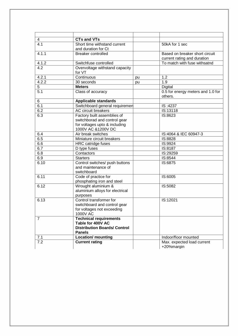
4 CTs and VTs
4.1 Short time withstand current and duration for Ct
50kA for 1 sec
4.1.1 Breaker controlled Based on breaker short circuit current rating and duration
4.1.2 Switchfuse controlled To match with fuse withsatnd
4.2 Overvoltage withstand capacity for VT
4.2.1 Continuous pu 1.2
4.2.2 30 seconds pu 1.9
5 Meters Digital
5.1 Class of accuracy 0.5 for energy meters and 1.0 for others.
6 Applicable standards
6.1 Switchboard general requirements IS :4237
6.2 AC circuit breakers IS:13118
6.3 Factory built assemblies of switchborad and control gear for voltages upto & including 1000V AC &1200V DC
IS:8623
6.4 Air break switches IS:4064 & IEC 60947-3
6.5 Miniature circuit breakers IS:8828
6.6 HRC catridge fuses IS:9924
6.7 D type fuses IS:8187
6.8 Contactors IS:29259
6.9 Starters IS:8544
6.10 Control switches/ push buttons and maintenance of switchboard
IS:6875
6.11 Code of practice for phosphating iron and steel
IS:6005
6.12 Wrought aluminium & aluminium alloys for electrical purposes
IS:5082
6.13 Control transformer for switchboard and control gear for voltages not exceeding 1000V AC
IS:12021
7 Technical requirements Table for 400V AC Distribution Boards/ Control Panels
7.1 Location/ mounting Indoor/floor mounted
7.2 Current rating Max. expected load current +20%margin

SWITCHGEAR COMPONENTS
ISOLATING SWITCH
a. All switches shall have visible ON/OFF position indication and shall be pad lockable in any (ON/OFF) position.
b. The switch shall be capable of making on to the system prospective symmetrical
fault current but limited in magnitude and duration by the cut off characteristics of largest HRC fuse link appropriate to the unit.
c. It shall not be possible to gain access to inside the unit unless the isolating
switch is in OFF position.
d. All isolating switches shall have 1 NO + 1 NC auxiliary contacts. Otherwise multiply where required as per schemes.
e. The switches shall be suitable for independent manual operation from the front
of the switchboard without opening the door.
f. The switch contacts shall be of silver alloy or silver plated copper and springs of non-corrosive material.
g. Interphase barriers shall be provided to prevent possibilities of phase-to-phase
fault in the switch. The switch shall also be shrouded from all sides to prevent access to live parts on the switch after opening the unit door. The barriers and shrouding shall extend upto the height of switch to fully enclose both the bus and the load side terminals of the device. The arrangement shall permit easy maintenance.
h. When used in combination with fuse and contactor; Switch shall be of quick make, quick break type to electrically isolate the starter
from the incoming supply. The device shall also interrupt the control supply. Switch shall be capable of disconnecting the load from the bus bars in case the
contactor has welded in and is carrying the stalled rotor current as high as 8 times full load current at a power factor of 0.3.
CONTACTORS
a. Contactors shall be of the air break type fitted with arc shields.
b. The operating coil shall be suitable for satisfactory operation in the range of
85% - 110% of nominal voltage specified under the Data Sheet A. The coil shall be tropicalized having insulation not less than class „E‟.
c. Butt contacts of the rolling self-cleaning type shall be utilized and all portions
likely to suffer from arcing shall be easily removable.

d. The contactor shall be capable of closing onto system prospective symmetrical fault current, as specified under Data Sheet A, backed up by the largest HRC fuse appropriate to the rating of the contactor. This capability shall be backed up by test results or calculations based on comparison of let-through energies.
e. Electrically independent auxiliary contacts not less than 2NO + 2NC for remote
interlocking and indication shall be fitted to individual contactor.
f. Main contacts of contactor shall be silver faced copper.
g. All springs shall be made out of a corrosion proof material.
h. Type of coordination with other devices shall be as per Data Sheet A. HIGH RUPTURING CAPACITY (HRC) FUSES
a. The fuse serving as the short-circuit protective device in contactor-starter or isolating fuse-switch units shall be of HRC cartridge, current limiting and plug-in/bolted non-deteriorating type.
b. The fuses carriers shall be easily withdraw able for replacement of fuse.
Insulated fuse pullers shall be provided where fuses are not mounted in insulating carriers to remove and replace fuses in live conditions.
c. Live terminals of fuse bases shall be shrouded to prevent contact with personnel
where fuse links are not mounted in carriers and are directly plugged into the fuse base. Interphase barriers extending throughout the length of the fuse base shall be provided to prevent interphase short circuit. They shall be shrouded from all sides to prevent accidental contact.
d. Fuse carriers and bases shall be of good quality moulded insulating material.
Porcelain fuse bases and carriers will not be accepted.
e. The rating and characteristics of fuse links shall be chosen appropriately for short circuit protection of circuits downstream, while fulfilling the following:
Remaining inoperative for transient conditions viz. starting in-rush current
of a motor downstream;
(b) Matching the thermal withstand characteristics of contactor and thermal overload device to the extent required as per type of coordination.
Condition (b) above is applicable where appropriate.

THERMAL OVERLOAD PROTECTION
a. All contactor starter for motor shall be provided with ambient temperature compensated thermal overload relay, closely matching the thermal withstand characteristics of motor and affording full protection under all conditions of loading.
b. Relay shall either have a pair of 1NO + 1NC contact or a set of change over
contacts.
c. The relay shall be hand reset type.
d. Attention shall be paid to the selection of proper overload relay for motors driving high inertia equipment and having long starting time. Relay shall have calibrated dial for site adjustment as per full load current of motor.
e. Current transformers where used for feeding the thermal over load relays shall
be exclusive for this purpose.
f. The resetting of the relay subsequent to its operation shall be possible without opening the compartment doors.
g. The setting range of relay chosen shall preferably be 80% - 120% of full load
current of corresponding motor, to allow for adjustment at site.
h. Thermal overload relays shall provide built in single phasing protection upto a minimum of 50% of motor full load current, unless separate single phasing protection is asked for. SINGLE PHASING PREVENTER
a. Unidirectional motors, shall have separate means of protection against single
phasing and unbalanced voltage.
b. Single phasing protection shall be of current monitoring type based on the principle of negative phase sequence current detection.
c. The relay to achieve the protection shall be provided with either a set of change
over contacts or a pair of 1 NO + 1 NC contacts.
d. The relay shall be hand reset type.
e. The relay shall be stable under such transient conditions as may occur on the system.
f. The relay shall provide effective protection under all conditions of loading.
g. The relay shall be inoperative during starting conditions with heavy inrush of
each motor.

h. It shall be possible to reset the relay after its operation without opening the compartment door.
INSTRUMENTS AND METERS
a. Meters to be fixed in the switchboard shall be panel mounted, flush type and
suitable for rear terminal connection.
b. Meters and instruments shall be enclosed in dust proof; moisture resistant black finished cases and shall be suitable for tropical use. Instruments shall be suitable for operation from the secondary windings of CTs and VTs.
c. All instruments shall be calibrated to enable direct reading of primary quantities.
Instruments shall be adjusted and calibrated at manufacturer‟s works and shall have means of calibration, checking and zero adjustment at site.
d. All the divisions and the quantity to be measured shall be clearly marked.
Instruments shall conform to applicable standard and shall have class 2 accuracy having black numerals and lettering on white anti- parallax dial with knife-edge pointer. Indicating instruments may be of moving iron type or taut band.
e. Ammeter, voltmeter and wattmeter shall have scale range 150% of the rated
circuit value. In motor circuits, the ammeter shall have suppressed scale to indicate eight times full load current. The ammeter shall have accuracy clause 2.5 for the suppressed scale.
f. Instruments having metallic cases shall be fitted with earthing terminals
PROTECTIVE AND AUXILIARY RELAYS
a. For proper protection of equipment, relays shall be provided on the various circuits. Relays shall have dust-tight, moisture-proof enclosure and shall be flush mounted type. Relay case shall be painted with dull black or eggshell black enamel and with back connected terminals. Metal cases and frames of relay shall be earthed.
b. All protection relays shall be of withdrawable type with built-in testing facilities,
with provision for inspection, maintenance and replacement. Where built-in test facility is not provided for a particular relay, separate suitable test block shall be provided on the panel for this purpose.
c. Relays shall have silver to silver contacts with wiping action and shall be capable
of making and carrying maximum currents of the associated circuit. Relay contacts shall be capable of breaking such current unless provision is made for breaking such currents elsewhere in the circuit. Contact of the relay shall be capable of repeated operation without deterioration.
d. Relays, which are connected to complete either the tripping circuits of circuit
breaker or the operation, coil of the tripping relay shall be fitted with an externally operated hand reset type mechanical flag indicator. Each indicator shall be

provided with inscription to identify the nature of faults. Indicator shall be capable of being reset by hand without opening the relay case.
e. Relay performance shall not alter due to mechanical shock or vibration or
external magnetic field, which may be present at the place of mounting.
f. Marking for the colour of the phase on which the relay is to be used shall be provided on the front.
g. Protective relays which initiate tripping shall not have less than two independent
pairs of contacts.
h. Current coils of relays shall be rated for the secondary current of the associated CT.
i. D.C. relays used for tripping shall operate even when the supply voltage is
reduced to 50% of rated voltage.
j. To minimize the effect of electrolysis, D.C. operating coils shall be so connected in the circuit such that they are not connected to the positive pole of the battery supply except through contacts which are normally open.
k. The relay ranges and actual settings shall be properly coordinated to achieve
adequate discrimination between various electrical equipment in the distribution system and at the same time ensure adequate safety to equipment protected.
l. Generally, the over current and earth fault protection shall have inverse time characteristics m. Invariably, breaker controlled motor feeders shall be provided with
Instantaneous over current protection.
Thermal overload protection.
Instantaneous earth fault protection.
Negative phase-sequence and unbalanced protection.
Stalling protection.
All these may be available as a composite relay.

CURRENT TRANSFORMERS (CT)
a. CTs shall be air insulated having insulation class E or better, cast resin type and shall be capable to withstand the thermal and mechanical stresses resulting from maximum short circuit and momentary current rating of the switchgear.
b. CTs for air circuit breakers shall be mounted on the fixed portion of the
switchgear (except CTs for built in release system) and remote from the bus bar.
c. CT primary current shall be as near as possible to, but not less than the full load thermal rating of the associated circuit. CT secondary shall have either 1Amp or 5Amp rating and polarity shall be marked in a suitable manner. The ratings shall be adequate to cater for the burden of connected instruments and relays, lead resistance and VA burden of remote instruments.
d. Protection CTs shall have an accuracy limit factor greater or equal to 10 and
accuracy class of 5P.
e. Measuring CTs shall have accuracy class 1.0 and instrument security factor of not more than 5.
f. Unused CT terminals must be short circuited at the terminal block.
g. Separate cores of CT shall be used for protection and metering.
h. CTs shall be of bar primary/ wound primary type capable of carrying the rated
primary current. VOLTAGE, CONTROL & HEATING TRANSFORMERS
a. Voltage transformers (VT) and control transformers (for contactor operation)
shall be dry, cast resin type comprising of single-phase units. They shall have their primary windings protected by current limiting fuses with interrupting capacity corresponding to that of the switchgear.
b. VT and control transformers secondary windings shall be earthed at the switchgear through link, which can be removed for insulation testing. The earthing shall be in conformity with the schemes enclosed.
c. Transformers shall have secondary voltages as per Data Sheet A.
d. All Bus VTs for protection/ metering shall have voltage rating of
(Nominal System Voltage / 3) / (110 / 3)
so that secondary voltage shall be 110 volts phase to phase when the secondary winding is star connected. The accuracy class of protection/metering VTs shall be 1.0. VTs shall have an output rating adequate to cater to the burden connected to them.

e. Control transformers used for motor contactor operation shall have output rating
adequate for proper and satisfactory operation of all the contactors fitted to the switchboard at the maximum secondary transient current with the minimum voltages prevailing on the bus.
f. Separate control transformer shall be provided for individual motor starter unit if
indicated in.
g. Winding heating transformer shall be provided as per the requirements indicated in Data Sheet A, if motor winding heating is envisaged and the same is mentioned in Data Sheet A.
CONTROL AND SELECTOR SWITCHES
a. The rating and other features of the switches shall be suitable for the application for the control and selector switch. The number of position and the number of contacts or ways required for each switch shall be as indicated.
b. Control and selector switches shall be stay put or spring return to neutral type,
provided with properly designated escutcheon plates clearly marked to show operating position.
c. The switches shall be suitable for semi-flush mounting with the front plate and
operating handle projecting out. All connection to the switches shall be from the back.
d. Circuit breaker control switches shall be arranged to operate in an anti-clock
wise direction when tripping.
e. Ammeter selector switches shall have make before break contacts.
f. The arrangement for front mounting of these devices shall be such as to make them reasonably dust free so as not to interfere with normal operation.
ELECTRICAL CONTROL SYSTEM
For electrical system [OTHER THAN MOTOR FEEDERS] of main plant, two types of controls systems are envisaged:
- CRT Control System [DDCMIS based]
- Hardwired Control System [Electrical Control Board]
Motor control is part of Process Control.
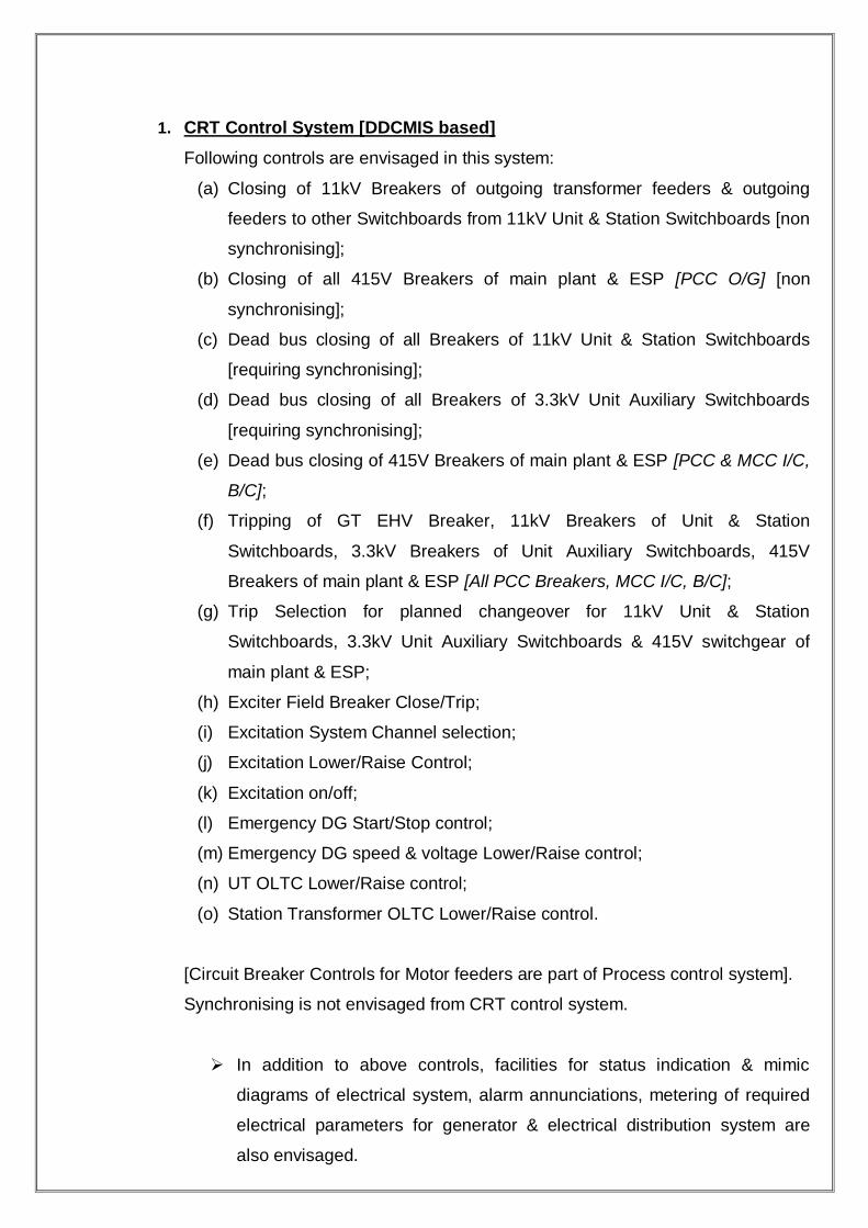
1. CRT Control System [DDCMIS based]
Following controls are envisaged in this system:
(a) Closing of 11kV Breakers of outgoing transformer feeders & outgoing
feeders to other Switchboards from 11kV Unit & Station Switchboards [non
synchronising];
(b) Closing of all 415V Breakers of main plant & ESP [PCC O/G] [non
synchronising];
(c) Dead bus closing of all Breakers of 11kV Unit & Station Switchboards
[requiring synchronising];
(d) Dead bus closing of all Breakers of 3.3kV Unit Auxiliary Switchboards
[requiring synchronising];
(e) Dead bus closing of 415V Breakers of main plant & ESP [PCC & MCC I/C,
B/C];
(f) Tripping of GT EHV Breaker, 11kV Breakers of Unit & Station
Switchboards, 3.3kV Breakers of Unit Auxiliary Switchboards, 415V
Breakers of main plant & ESP [All PCC Breakers, MCC I/C, B/C];
(g) Trip Selection for planned changeover for 11kV Unit & Station
Switchboards, 3.3kV Unit Auxiliary Switchboards & 415V switchgear of
main plant & ESP;
(h) Exciter Field Breaker Close/Trip;
(i) Excitation System Channel selection;
(j) Excitation Lower/Raise Control;
(k) Excitation on/off;
(l) Emergency DG Start/Stop control;
(m) Emergency DG speed & voltage Lower/Raise control;
(n) UT OLTC Lower/Raise control;
(o) Station Transformer OLTC Lower/Raise control.
[Circuit Breaker Controls for Motor feeders are part of Process control system].
Synchronising is not envisaged from CRT control system.
In addition to above controls, facilities for status indication & mimic
diagrams of electrical system, alarm annunciations, metering of required
electrical parameters for generator & electrical distribution system are
also envisaged.
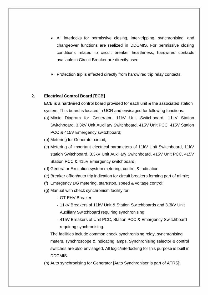
All interlocks for permissive closing, inter-tripping, synchronising, and
changeover functions are realized in DDCMIS. For permissive closing
conditions related to circuit breaker healthiness, hardwired contacts
available in Circuit Breaker are directly used.
Protection trip is effected directly from hardwired trip relay contacts.
2. Electrical Control Board [ECB]
ECB is a hardwired control board provided for each unit & the associated station
system. This board is located in UCR and envisaged for following functions:
(a) Mimic Diagram for Generator, 11kV Unit Switchboard, 11kV Station
Switchboard, 3.3kV Unit Auxiliary Switchboard, 415V Unit PCC, 415V Station
PCC & 415V Emergency switchboard;
(b) Metering for Generator circuit;
(c) Metering of important electrical parameters of 11kV Unit Switchboard, 11kV
station Switchboard, 3.3kV Unit Auxiliary Switchboard, 415V Unit PCC, 415V
Station PCC & 415V Emergency switchboard;
(d) Generator Excitation system metering, control & indication;
(e) Breaker off/on/auto trip indication for circuit breakers forming part of mimic;
(f) Emergency DG metering, start/stop, speed & voltage control;
(g) Manual with check synchronism facility for:
- GT EHV Breaker;
- 11kV Breakers of 11kV Unit & Station Switchboards and 3.3kV Unit
Auxiliary Switchboard requiring synchronising;
- 415V Breakers of Unit PCC, Station PCC & Emergency Switchboard
requiring synchronising.
The facilities include common check synchronising relay, synchronising
meters, synchroscope & indicating lamps. Synchronising selector & control
switches are also envisaged. All logic/interlocking for this purpose is built in
DDCMIS.
(h) Auto synchronising for Generator [Auto Synchroniser is part of ATRS];

(i) Dead bus closing of 11kV Unit & Station Switchboard Breakers, 3.3kV Unit
Auxiliary Switchboard, 415V Breakers of Unit PCC, Station PCC &
Emergency Switchboard [requiring synchronising];
(j) Closing of transformer outgoing & tie outgoing feeders from 11kV Unit &
Station Switchboards;
(k) Tripping of all breakers forming part of the mimic [for which
synchronising/closing facility is provided on ECB].
(l) Alarm Annunciation facia windows [for common alarms and troubles].
The operation philosophy for control of circuit breakers from ECB is given below:
i) The breaker to be controlled is selected by means of an illuminated push-
button.
ii) This activates common circuit breaker control switch, common synchronising
mode selector switch and common trip selector switch and associated LEDs
as applicable.
iii) The selected circuit breaker is controlled now through common circuit
breaker control switch.
iv) Resetting of Circuit breaker selector push button, common circuit breaker
control switch, common synchronising mode selector switch, common trip
selector switch and associated LEDs as applicable is done by means of a
common control reset push button.
Logic/interlocking to achieve above operations is suitably built in DDCMIS.
Theoretical explanation for Circuit Breakers controlled from DCS only This is a logical explanation for circuit breakers controlled from DCS. DCS is the abbreviated form for Distributed Control System. We have taken the case of control of outgoing feeders from 6.6 kv Unit Switchboard as shown in the diagram. The control diagram shows the (i) Closing of O/G FDR CB. (ii) Tripping of O/G FDR CB. With reference to the Simplified One Line Diagram and the table given along with Control Logic for O/G FDR :
1) I/C CB: 1CB011 and 1CB13.
2) B/C CB: 1CB012.
Condition for which O/G CB has to be closed:

i) When either of the I/C CB is closed(OR gate is used).
ii) The O/G CB itself is open.
iii) We give the instruction as CB CLOSE ( * ).
iv) The CB is chosen B<CB TAG>.
If all the above conditions are satisfied (as the instructions are sent through an AND gate) , then only a time pulse of 0.50 sec. is sent to the switch-gear to close the O/G CB. Condition for which O/G CB has to be tripped:
i) When the O/G CB is closed.
ii) When both of the I/C CB are open.
For the first condition, we give three instruction as shown in the logic control diagram : CB TRIP (*) as an insturtion to trip, B<CB TAG> to select, The state of the O/G CB(i.e closed). If the three clauses are satisfied, then it is passed through a current transformer. For the second condition, we take the following considerations as given in the logic control diagram : O/G CB is closed. Both the I/C CB are open. If the above clauses are satisfied, then it is passed through a potential transformer. If either of the above two conditions are satisfied( as passed through an OR gate), a pulse is sent from the DCS to the switch-gear to trip the O/G CB.

BATTERY, CHARGERS, DISTRIBUTION BOARDS AND STARTER PANELS
220V DC system is provided for unit and station DC loads like switchgear,
protection, emergency lighting, DC drives etc.
1. 220V DC Battery and Battery chargers
For each unit, the 220V system comprises of two sets of batteries with an
associated float-cum-boost charger for each battery.
220V batteries are sized to meet respective DC loads following an
emergency for a duty cycle of thirty (30) minutes. Each battery is rated to
cater for 100% loads. A 10% design margin is considered in battery
capacity. Suitable ageing factors and electrolyte temperature correction
factors are also considered.
In float mode, each battery charger is capable of meeting continuous
normal DC power requirement and trickle charging the connected battery.
For boost mode, the battery charger is sized to recharge the fully
discharged battery to its normal capacity in a period of about 10 hours. A
design margin of 10% is considered in selecting rating of the charger in the
respective modes.
The batteries are stationary, lead-acid type. The batteries are complete
with connectors & other accessories and supported on racks.
The chargers are of static type, comprising of silicon-controlled rectifiers
connected in three phase, full wave, full controlled bridge circuit. The
charger is provided with auto and manual voltage regulation. The charger
panels have a degree of protection of IP: 42.
Following protections are provided for the batteries and the battery chargers:
Fuse/MCCB for short circuit protection of battery.
Earth fault protection.
Current limiting, DC under voltage & over-voltage and AC
under voltage protection for charger.

2. 220V DC Distribution Board (DCDB)
A 220V DC Distribution Board is envisaged for feeding DC loads of each
unit and associated station equipment.
220V DCDB is indoor, metal enclosed, modular construction, fixed
execution, floor-mounted type. Two nos. feeders of adequate rating are
taken from battery/charger for the incomers of this board. The degree of
protection of these panels is IP: 52. Switchfuse units are considered for
outgoing and incoming feeders. Bus-sectionaliser is provided.
The general constructional features of 220V DCDB are similar to those
described under LV Switchgear, as applicable for distribution boards (DBs)

The diagram below shows the LT switchgear connections and
feeders for UNIT 5 BTPS.
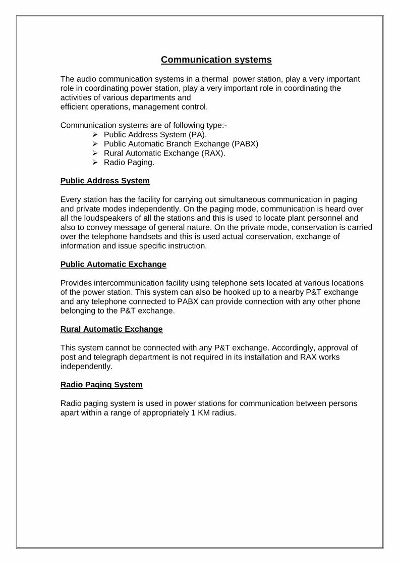
Communication systems The audio communication systems in a thermal power station, play a very important role in coordinating power station, play a very important role in coordinating the activities of various departments and efficient operations, management control. Communication systems are of following type:-
Public Address System (PA). Public Automatic Branch Exchange (PABX) Rural Automatic Exchange (RAX). Radio Paging.
Public Address System
Every station has the facility for carrying out simultaneous communication in paging and private modes independently. On the paging mode, communication is heard over all the loudspeakers of all the stations and this is used to locate plant personnel and also to convey message of general nature. On the private mode, conservation is carried over the telephone handsets and this is used actual conservation, exchange of information and issue specific instruction. Public Automatic Exchange Provides intercommunication facility using telephone sets located at various locations of the power station. This system can also be hooked up to a nearby P&T exchange and any telephone connected to PABX can provide connection with any other phone belonging to the P&T exchange. Rural Automatic Exchange
This system cannot be connected with any P&T exchange. Accordingly, approval of post and telegraph department is not required in its installation and RAX works independently. Radio Paging System
Radio paging system is used in power stations for communication between persons apart within a range of appropriately 1 KM radius.

Generator control
1. The control, monitoring, measurement, annunciation, synchronising and
sequential event logging for each generator and its subsystem shall be provided
on the DCS.
2. Generator And Auxiliary Power Supply System Control &Monitoring
I. Provision in the plant control system shall be made for the starting, bringing
rated voltage and speed, initiation of synchronising, operation, annunciation and
monitoring, alarm, data logging, recording and sequential event recording for
generator and its excitation system from the DCS. The minimum requirements of
the measurements are indicated in the Main One Line diagram
II. One no. Of synchronising panel/trolley shall be provided through which the
synchronising of all the GCB &breakers in 220 kV switchyard can be
synchronised by plugging the control cable into socket provided on each Control
panel of the respective breaker. This synchronising trolley shall have all the
necessary equipments &meters for carrying out the manual synchronisation. The
Raise/Lower commands for carrying out the manual synchronisation. The
Raise/Lower commands for the same also be done through the trolley itself.
Apart from this the Auto synchronising facility shall be made available to auto
synchronise the above breakers through DCS.
III. The interlocks for the auxiliary power supply system shall be hard wired
interlocks.
3. Control and monitoring in DCS
I. Control, monitoring, measurement, annunciation, synchronising of complete
electrical system supplied under this contract shall be possible from plant DCS
system. In case of failure of any OS, it shall be possible to carry out the
necessary operation from one of the healthy OS. Synchronising, essential
controls, metering and annunciation shall also be available from the Respective
control panels for the lines.
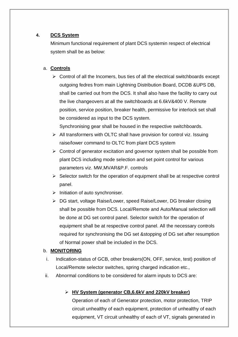
4. DCS System
Minimum functional requirement of plant DCS systemin respect of electrical
system shall be as below:
a. Controls
Control of all the Incomers, bus ties of all the electrical switchboards except
outgoing fedres from main Lightning Distribution Board, DCDB &UPS DB,
shall be carried out from the DCS. It shall also have the facility to carry out
the live changeovers at all the switchboards at 6.6kV&400 V. Remote
position, service position, breaker health, permissive for interlock set shall
be considered as input to the DCS system.
Synchronising gear shall be housed in the respective switchboards.
All transformers with OLTC shall have provision for control viz. Issuing
raise/lower command to OLTC from plant DCS system
Control of generator excitation and governor system shall be possible from
plant DCS including mode selection and set point control for various
parameters viz. MW,MVAR&P.F. controls
Selector switch for the operation of equipment shall be at respective control
panel.
Initiation of auto synchroniser.
DG start, voltage Raise/Lower, speed Raise/Lower, DG breaker closing
shall be possible from DCS. Local/Remote and Auto/Manual selection will
be done at DG set control panel. Selector switch for the operation of
equipment shall be at respective control panel. All the necessary controls
required for synchronising the DG set &stopping of DG set after resumption
of Normal power shall be included in the DCS.
b. MONITORING
i. Indication-status of GCB, other breakers(ON, OFF, service, test) position of
Local/Remote selector switches, spring charged indication etc.,
ii. Abnormal conditions to be considered for alarm inputs to DCS are:
HV System (generator CB,6.6kV and 220kV breaker)
Operation of each of Generator protection, motor protection, TRIP
circuit unhealthy of each equipment, protection of unhealthy of each
equipment, VT circuit unhealthy of each of VT, signals generated in
Transformer MB about abnormal operating conditions of Transformer,
LBB operation of each breaker, DC supply failure of each
protection/control scheme as appropriate, Successful/Unsuccessful
changeover of 6.6kV supplies.GT and UAT condition shall be
monitored from DCS.
LV System (400)
Breaker auto trip, individual protective relay operation trip relay failure,
DC supply failure, bus under voltage, VT fuse failure, Trip circuit
unhealthy. Successful / Unsuccessful changeover of 400kV supplies.
Generator, Unit Auxiliary &Service Transformers
All alarm and trip conditions of generator transformers, unit auxiliary
transformers and service transformers. Monitoring of winding &of all
temperatures &pressure parameters related to Generator.
DC System
DC earth fault, DC under voltage, group faults in case of DC boards,
and normal operating parameters of the DC system etc.,
UPS System
All normal & abnormal conditions of UPS system in details
Battery Charger
Group trouble alarm for chargers with details as available from
equipment.
Excitation System and Generator
Each of protection relay and trip conditions, abnormal conditions in
excitation system and generator.
DG Set
DG operating parameters, alarm and trip conditions.
Alarm for the running hours of 30kW &above motors shall be
generated after achieving predefined set points.
Monitoring of the complete electrical system during the normal
operation.
Temperatures of all the>=100KW motors.
All the energy parameters of the lines, generator &auxiliary
consumption shall be taken from the ABT compliant energy meters
through communication

iii. Single line diagram showing Voltage, frequency, MW and MVAR flows,
breaker and isolator positions shall be available on DCS. More than one
frame can be used if all the details cannot be represented on single frame.
I. Event logging shall be provided for all manual operations and relay operations
as detailed below:
(a) Status of each breaker of all equipment being controlled, isolators and earth
switches.
(b) Close and open commands
(c) Selector switch positions.
(d) Each protective relay, trip relay, alarm relay operation. Event logging for each
phase shall be provided wherever applicable (e.g. 3-poles of line circuit breaker,
distance relay output contacts, generator protections, fuse fail alarm, etc.)
(e) Event logger shall be a part of the DCS with first up feature. It shall have a time
resolution of 1ms.
(f) Trip contacts of the complete electrical installation/equipments in the station viz.
Battery charger, UPS Generator, all transformer, electrical switchboards etc. Are
to be included.
II. Trending of parameters during disturbance shall be with resolution of 0.5/1.9
sec., and at 15 minutes during normal operation. The change from normal mode
to disturbance mode shall be through threshold/gradient settings provided in the
system for analog quantities and external binary signals obtained from selected
protective relays. Capturing of momentarily values of all these parameters shall
also be possible triggered either by a protective relay or by a manual keyboard
command.
5. Synchronising
Generator (Manual and through auto synchroniser).
Synchronising facility shall be provided for the generator through auto
synchroniser in auto mode and with the help of double voltmeter, double
frequency meter, and synchroscope and check synchronising relay permissive
condition in the manual mode.
6.6kV Incomer &tie circuit breakers shall have facility for fast and slow auto
changeover/manual synchronising and dead bus closing.

400V switch board /MCC incomer and bus coupler breakers shall have facility for
dead bus auto changeover/ manual live transfer.
Synchronizing facility with check feature has been provided for all 220KV breakers.
Whenever a breaker is proposed to be closed, its synchronizing switch should be
unlocked and synchronizing check relay by pass switch is in circuit position. It is
ensured that voltage and frequency of the incoming and running supplies are nearly
same, and the red „out of synchronism lamp is not continuously on. After the breaker
has been closed, its synchronizing switch should be returned to off position and
locked.
Synchronizing check relay SKE prevents closing of a breaker when incoming
and running supplies are out of synchronism. This relay has to be
bypassed when closing a breaker one side of, which is dead.
One (!) set of synchronising equipment consisting of double voltmeter, double
frequency meter, synchroscope, check synchronising relay, synchronising lamps,
synchroniser with lockable only in „Off‟ position, etc., shall be provided for each of
the following
Generator
Breaker associated with Emergency DG synchronising.
6. The functional requirement indicated above is minimum.
LINE FAULT DETECTORS
Y3
EARTH FAULT DETECTORS 64
ZONE
TIMING 2
EARTH FAULT REACTANCE UNITS X2
RANGE
EXTENSION 2X2X
DETECTOR AUXILIARIES
Y3X
7. The time critical controls and interlocks shall be hard wired system only
.
8. The control/selector switches and meters shall be of miniaturised.
9. Meter-ABT complain Tri-vector meters of accuracy class shall be 0.2s for lines,
UAT and generator metering.
10. Transducers
I. The contractor shall provided all the transducers for electrical system either in
respective switchgear/control panels. All the transducers shall be self-powered.
II. The transducers shall comply with the requirements specified for transducers in
electrical section.
11. Interposing Relays
I. The interposing relays required for the switchgear/equipment being supplied
under this contract shall be located in respective modules of switchgear/ relay
panels.
II. The coupling relays shall be rated for 0.5 Amp breaking at 220 V DC and 6 Amp
make and continuous current at 220 V Dc.
III. Interposing relays used for 220 kV circuit breaker closing shall be adequately
rated for the making current.

HIGH SPEED PROTECTION THROUGH THE SUE 3000 HIGH
TRANSFER DEVICE
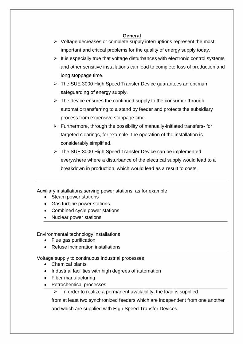
General
Voltage decreases or complete supply interruptions represent the most
important and critical problems for the quality of energy supply today.
It is especially true that voltage disturbances with electronic control systems
and other sensitive installations can lead to complete loss of production and
long stoppage time.
The SUE 3000 High Speed Transfer Device guarantees an optimum
safeguarding of energy supply.
The device ensures the continued supply to the consumer through
automatic transferring to a stand by feeder and protects the subsidiary
process from expensive stoppage time.
Furthermore, through the possibility of manually-initiated transfers- for
targeted clearings, for example- the operation of the installation is
considerably simplified.
The SUE 3000 High Speed Transfer Device can be implemented
everywhere where a disturbance of the electrical supply would lead to a
breakdown in production, which would lead as a result to costs.
Auxiliary installations serving power stations, as for example
Steam power stations
Gas turbine power stations
Combined cycle power stations
Nuclear power stations
Environmental technology installations
Flue gas purification
Refuse incineration installations
Voltage supply to continuous industrial processes
Chemical plants
Industrial facilities with high degrees of automation
Fiber manufacturing
Petrochemical processes
In order to realize a permanent availability, the load is supplied
from at least two synchronized feeders which are independent from one another
and which are supplied with High Speed Transfer Devices.

In doing so, the High Speed Transfer Device has the task of ensuring
uninterrupted continues operation of the connected devices in case of a
power supply break down, taking into account different physical factors,
through the most rapid possible transfer to a different feeder kept stand-by.
Corresponding, to its multifaceted areas o f application,
The SUE 3000 is set up for different switchgear arrangement.
Switchgear configuration with two
circuit breakers
i. This arrangement is often used in auxiliary installations serving thermal power
plant stations.
ii. One of the two power supplies normally feeds the bus bar.
iii. One of the two is switched on, the other is switched off.
iv. A coupled operation of both power supplies is not intended, and due to
reasons of rating (short circuit withstand), it is often also not permissible.
v. If an error leads to a disturbance of the feeder currently in operation, the
transfer device switches the load over to the second feeder in the shortest
possible time.
vi. Following successful transfer, the bus bar is then supplied further by the
second feeder.
vii. Once the main feeder is again in operation, a manually initiated transfer back
can take place and the normal status can be restored once again.
viii. The high speed transfer device SUE 3000 is designed completely symmetrical,
so that a protection-initiated transfer can be executed from either of the
feeders, in case for example two feeders with equal status are present.
ARRANGEMENT WITH TWO FEEDERS AND ONE
BUSBAR COUPLING
i. With this configuration, the load is divided between two bus bar sections due to
reasons of redundancy.
ii. The coupling circuit-breaker usually remains open.
iii. Both feeders are in operation.
iv. In case of disturbance of one feeder, these follow a transfer from the circuit
breaker of the disturbed feeder to the coupling circuit breaker.

v. The circuit breaker which had previously been the feeder is opened and the
bus bar coupling is closed.
vi. After that, both bus bar sections are supplied by one feeder.
vii. Once the disturbed is again available, a manually-initiated transfer back can be
executed in order to restore normal status once again.
Prerequisites for the optimum utilization of the Sue 3000
In order to ensure optimal utilization of the SUE 3000, the following prerequisites should be fulfilled:
Existence of at least two synchronous feeders, which are independent of one another during normal operation. Circuit breaker with short operating time
Switchgear assembly/ load suitable for network transfers
Fast protective relays for initiation of the High Speed Transfer Device In case of disturbance leading to the breakdown of the distribution voltage, an
interruption is avoided through the automatic intervention of the High Speed
Transfer Device.
Transfers can continue to be manually triggered, depending on operation.
The enhancement of the installation availability leads to considerable cost savings
and to a short- term amortization of the investment.
Even just one single successful transfer, who ensures the continued operation of an
installation, prevents stoppage time and saves on expensive re-initialization
processes, can mean a complete amortization of the investment costs for the High
Speed Transfer Device.
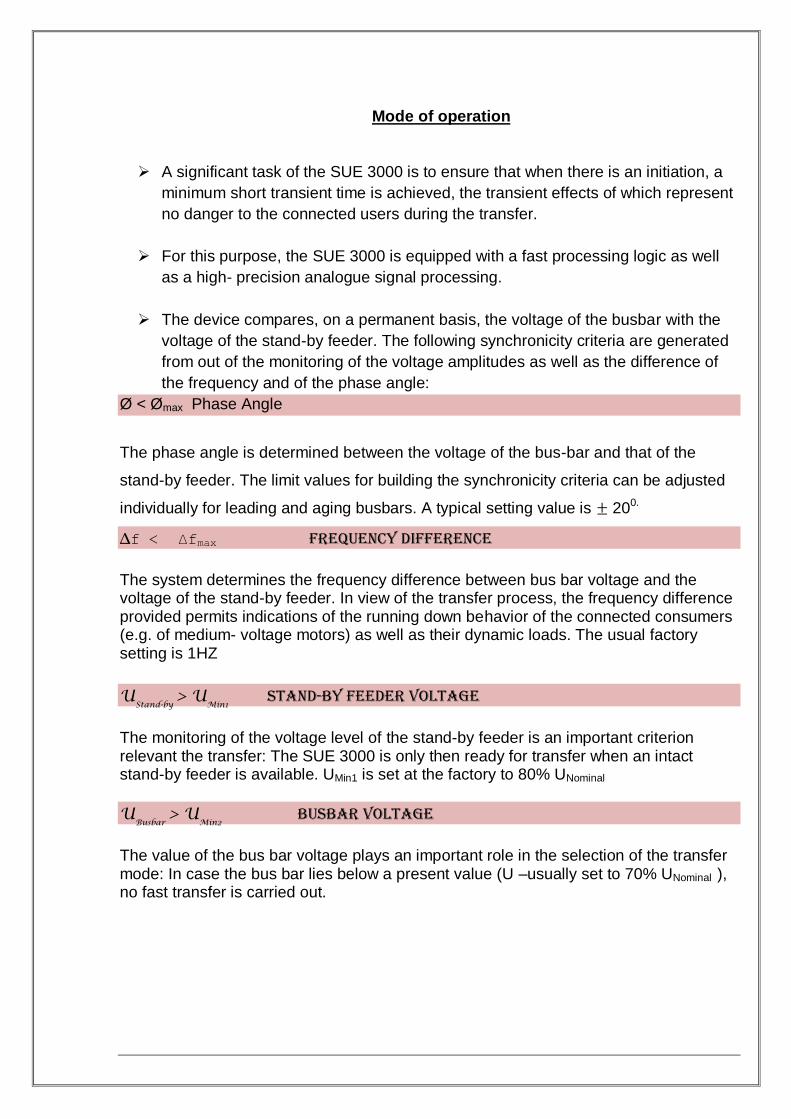
Mode of operation
A significant task of the SUE 3000 is to ensure that when there is an initiation, a
minimum short transient time is achieved, the transient effects of which represent
no danger to the connected users during the transfer.
For this purpose, the SUE 3000 is equipped with a fast processing logic as well
as a high- precision analogue signal processing.
The device compares, on a permanent basis, the voltage of the busbar with the
voltage of the stand-by feeder. The following synchronicity criteria are generated
from out of the monitoring of the voltage amplitudes as well as the difference of
the frequency and of the phase angle:
Ø < Ømax Phase Angle
The phase angle is determined between the voltage of the bus-bar and that of the
stand-by feeder. The limit values for building the synchronicity criteria can be adjusted
individually for leading and aging busbars. A typical setting value is 200.
∆f < ∆fmax frequency difference The system determines the frequency difference between bus bar voltage and the voltage of the stand-by feeder. In view of the transfer process, the frequency difference provided permits indications of the running down behavior of the connected consumers (e.g. of medium- voltage motors) as well as their dynamic loads. The usual factory setting is 1HZ
U
Stand-by > U
Min1 stand-by feeder voltage
The monitoring of the voltage level of the stand-by feeder is an important criterion relevant the transfer: The SUE 3000 is only then ready for transfer when an intact stand-by feeder is available. UMin1 is set at the factory to 80% UNominal
UBusbar
> UMin2
Busbar voltage The value of the bus bar voltage plays an important role in the selection of the transfer mode: In case the bus bar lies below a present value (U –usually set to 70% UNominal ), no fast transfer is carried out.

Permanent determination of the network conditions An exceptionally important characteristics of the SUE 3000 High Speed Transfer Device is that the synchronicity criteria named are continuously available, e.g. that they are computed on-line by the SUE 3000. For that reason, in case of an initiation, the transfer mode which comes under consideration is already determined and can be immediately initiated. This means that the probability of a fast transfer is considerably enhanced. Systems which wait for the instant of initiation to initiate the determination of the network status have no opportunity, when one considers the physical givens, to perform a fast transfer with minimum interruption time.
This fact clearly distinguishes the high speed transfer device sue 300 from competing concepts. The high speed transfer device is ready for operation only when both circuit breakers to be actuated are definitely to be found in different switching statuses (plausibility monitoring) and also in operating position. Transfer modes
Decisive for the kind of transfer carried out are the network relationships in the instant of initiation of the High Speed Transfer Device. Here the corresponding optimum transfer mode is selected, taking the physical interrelationships into consideration. Four different transfer modes are available in detail:
Fast Transfer
Transfer at the 1st phase coincidence
Residual voltage transfer Time –operated transfer The fast transfer is the optimum transfer mode for ensuring in case of fault that only a minimum interruption of the voltage supply occurs. Should it be that the network status does not permit this mode, and then less rapid transfer modes are selected. Figure5.1 shows the typical decay characteristics (voltage and frequency) of a disconnected bus bar and the possible closing moments.

The transfer modes are explained in brief below:
Fast Transfer
The execution of fast transfers is the most preferred and most important
functional principle of the SUE 3000
A fast transfer takes place when the both the main and the stand-by feeder are
within specified limit values at the moment of initiation, e.g. that slip and phase
angle are limited between the networks and the stand-by voltage lies above a
minimum value.
Here the open and close commands to the circuit breaker from the High Speed
Transfer Device are issued as a rule synchronously.
The current-free transfer time occurring in this case for the users is exclusively
dependent upon the difference between the operating time for closing and
opening the circuit concerned.
Because these usually fall within the range of a few milliseconds with modern
circuit breakers, one can assume an uninterrupted further operation of the
installation.
An exemplary oscillogram of a fast transfer with a current transfer time (dead
time) of appropriately 20 ms.
1. Bus bar voltage 2. Current feeder 1 3. Current feeder2 4. Trip time 5. Dead time
Note Fast transfer condition/synch. Condition
Line Voltage > Set Value (min 85%) & Max 110%
Bus Voltage > Set Value (Min 80%)
Phase Angle diff. Between Unit Bus 1CA & 1CB volt.<Set Value (Max
20o)
Phase Diff. Between Unit I/C -1 & 1CA Volt. <Set Value
(Min 200) Slow transfer condition
Fast Transfer Has Failed
Bus Voltage <Set Value (Max 20%)
I/C -1 & B/C OFF For B/C Close, B/C OFF For I/C-1 Close.
Under Normal Working Condition I/C-1 and I/C-2 ON And B/C Off.
Similar Logic Shall Be Applicable For I/C-2 Also.
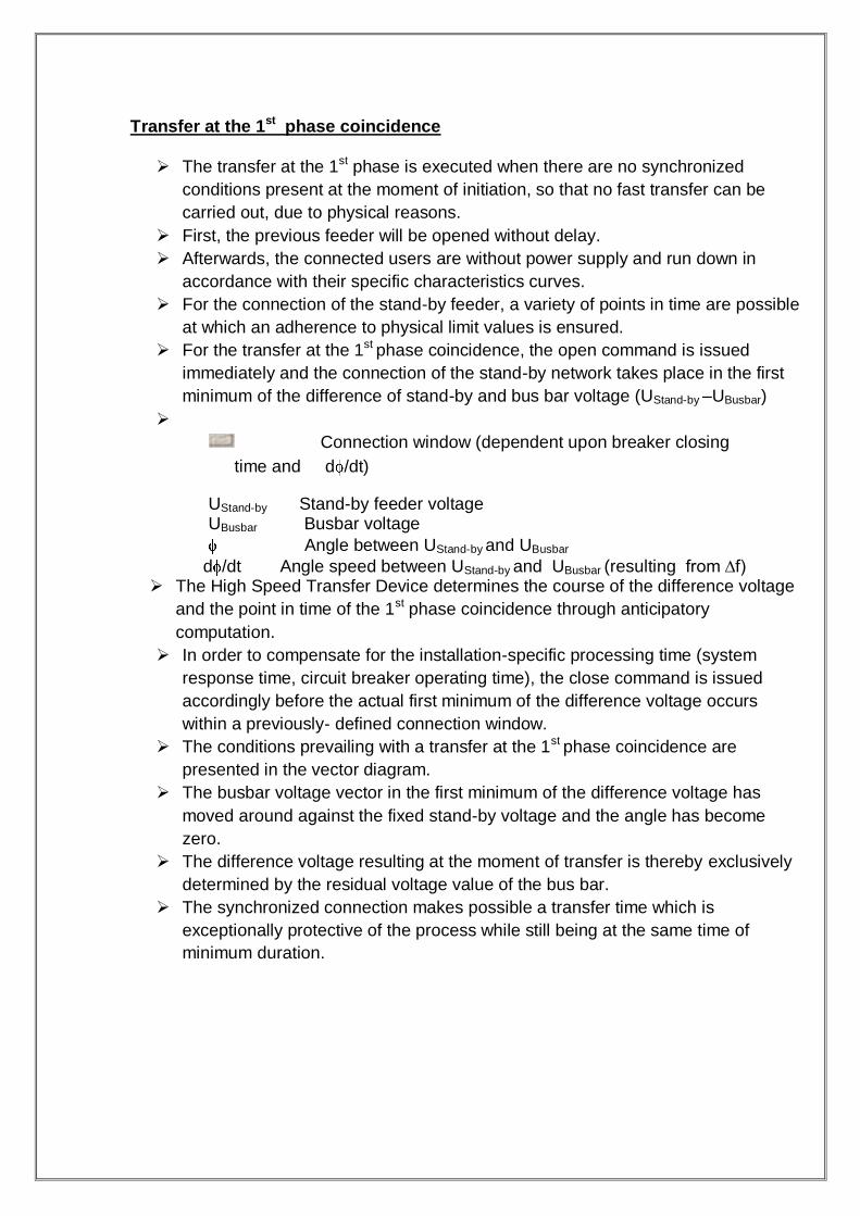
Transfer at the 1st phase coincidence The transfer at the 1st phase is executed when there are no synchronized
conditions present at the moment of initiation, so that no fast transfer can be
carried out, due to physical reasons.
First, the previous feeder will be opened without delay.
Afterwards, the connected users are without power supply and run down in
accordance with their specific characteristics curves.
For the connection of the stand-by feeder, a variety of points in time are possible
at which an adherence to physical limit values is ensured.
For the transfer at the 1st phase coincidence, the open command is issued
immediately and the connection of the stand-by network takes place in the first
minimum of the difference of stand-by and bus bar voltage (UStand-by –UBusbar)
Connection window (dependent upon breaker closing
time and d /dt)
UStand-by Stand-by feeder voltage UBusbar Busbar voltage
Angle between UStand-by and UBusbar
d /dt Angle speed between UStand-by and UBusbar (resulting from ∆f) The High Speed Transfer Device determines the course of the difference voltage
and the point in time of the 1st phase coincidence through anticipatory
computation.
In order to compensate for the installation-specific processing time (system
response time, circuit breaker operating time), the close command is issued
accordingly before the actual first minimum of the difference voltage occurs
within a previously- defined connection window.
The conditions prevailing with a transfer at the 1st phase coincidence are
presented in the vector diagram.
The busbar voltage vector in the first minimum of the difference voltage has
moved around against the fixed stand-by voltage and the angle has become
zero.
The difference voltage resulting at the moment of transfer is thereby exclusively
determined by the residual voltage value of the bus bar.
The synchronized connection makes possible a transfer time which is
exceptionally protective of the process while still being at the same time of
minimum duration.
Summary
A very important characteristic of the SUE 3000 high speed transfer Device is that the selection of the transfer mode carried out takes place dynamically in connection with respective current network relationships.
If one starts from the premises of networks which are usually synchronized, then fast transfers as a general rule will be carried out.
The principle they, embody of the simultaneous issuing of commands makes it possible to have short transfer time with nearly uninterrupted continued supply of the switch-over process.
In cases of mechanical failure in the circuit breaker to be switched off, a short-term coupling occurs between the two (synchronized) feeders, which is however detected by the SUE 3000 and automatically cancelled again, in order to avoid a impermissible coupling of the networks
If the networks are not synchronized at the point of time of the initiation,
then no fast transfer takes place. The current-free interlude time that then arise are different, depending on the installation involved, whereby the load to be switched over determines the run-down behavior of the bus-bar voltage and with it the transfer duration.
The various transfer types can be selectively activated or deactivated, in a
way dependent on the orientation. Thus it is ensured that, in accordance with the special requirements, the optimum transfer concept can be released for the overall installation.
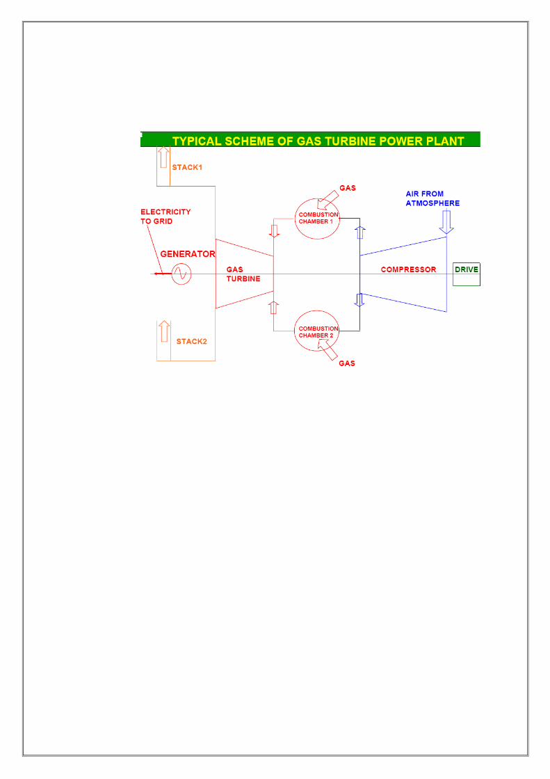
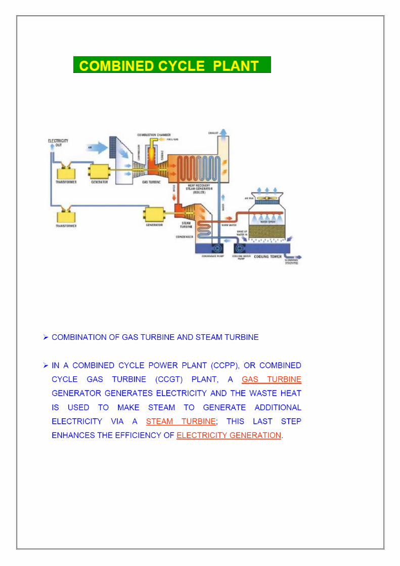
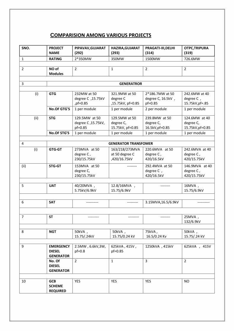
COMPARISION AMONG VARIOUS PROJECTS
SNO. PROJECT NAME
PIPAVAV,GUJARAT (292)
HAZIRA,GUJARAT (293)
PRAGATI-III,DELHI (314)
OTPC,TRIPURA (319)
1 RATING 2*350MW 350MW 1500MW 726.6MW
2 NO of Modules
2 1 2 2
3 GENERATROR
(i) GTG 232MW at 50 degree C ,15.75kV ,pf=0.85
321.9MW at 50 degree C ,15.75kV, pf=0.85
2*186.7MW at 50 degree C, 16.5kV , pf=0.85
242.6MW at 40 degree C , 15.75kV,pf=.85
No.OF GTG'S 1 per module 1 per module 2 per module 1 per module
(ii) STG 129.5MW at 50 degree C ,15.75kV, pf=0.85
129.5MW at 50 degree C, 15.75kV, pf=0.85
239.8MW at 50 degree C, 16.5kV,pf=0.85
124.6MW at 40 degree C, 15.75kV,pf=0.85
No.OF STG'S 1 per module 1 per module 1 per module 1 per module
4 GENERATOR TRANSFOMER
(i) GTG-GT 273MVA at 50 degree C , 230/15.75kV
163/218/273MVA at 50 degree C ,420/16.75kV
220.6MVA at 50 degree C , 420/16.5kV
242.6MVA at 40 degree C , 420/15.75kV
(ii) STG-GT 153MVA at 50 degree C, 230/15.75kV
-------- 292.4MVA at 50 degree C , 420/16.5kV
146.9MVA at 40 degree C , 420/15.75kV
5 UAT 40/20MVA , 5.75kV/6.9kV
12.8/16MVA , 15.75/6.9kV
-------- 16MVA , 15.75/6.9kV
6 SAT ---------- --------- 3.15MVA,16.5/6.9kV ----------
7 ST --------- --------- -------- 25MVA , 132/6.9kV
8 NGT 50kVA , 15.75/.24kV
50kVA , 15.75/0.24 kV
75kVA , 16.5/0.24 Kv
50kVA , 15.75/.24 kV
9 EMERGENCY DIESEL GENERATOR
2.5MW , 6.6kV,3W, pf=0.8
625kVA , 415V , pf=0.85
1250kVA , 415kV 625kVA , 415V
No. Of DIESEL GENERATOR
2 1 3 2
10 GCB SCHEME REQUIRED
YES YES YES NO