Embed Size (px)
Citation preview

Report on
Replacement of old RTU
in Eastern Region for
reporting of RTU / SAS to
back-up control centre
ByNominated Committee
Members
Submitted to ERPC
Version: 0 dated: 23rd August 2017

Report of RTU / SAS replacement in Eastern Region
Page 1
Report on Replacement of old RTU in Eastern Region for reporting of RTU / SAS to back-up control centre
Contents Preface ................................................................................................................................................ 2
Executive Summary ..................................................................................................................... 3
1. Background: ......................................................................................................................... 5
2. Committee Members: ...................................................................................................... 7
3. Scope of the work: ........................................................................................................... 7
4. Architecture: ........................................................................................................................ 7
5. List of RTU/SAS to be replaced: ................................................................................ 9
6. Major Findings: ................................................................................................................. 10
7. Conclusion & Recommendation: ............................................................................. 11
PREPARED BY: NOMINATED COMMITTEE MEMBERS
SUBMITTED TO: ERPC, KOLKATA.
Report of RTU / SAS replacement in Eastern Region
Page 2
Preface
This project report is all about Identification & replacement of old RTU/SAS which are not feasible
for dual reporting over IEC104 protocol. POWERGRID ULDC team mentioned in the 19th SCADA O&M
meeting held at ERLDC, Kolkata on 07th April 2017 that there would not be any service support for
the old RTUs from POWERGRID after 15 years of operation period due to scarcity of spare parts as
well OEM service is not feasible any more.
India had witnessed two massive grid disturbances on 30th & 31st July 2012 wherein major parts of
Northern, Eastern & North-Eastern Regional affected. Subsequently, it was emphasized to create a
back-up control centre at a different location as recommended by Intelligence Bureau. Purpose of
backup ERLDC control centre located at NLDC, New Delhi could not be fulfilled unless until all RTUs
are dually reported to both the control centres. Presently, old RTUs/SAS doesn’t have facility of data
reporting dually to two different control centre over IEC 60870-5-104 also maintenance is not
possible.
---***---
Report of RTU / SAS replacement in Eastern Region
Page 3
Executive Summary Power System Operation Corporation Limited (POSOCO), a Government of India Enterprise, is the
apex body to ensure integrated operation of power system including scheduling and despatch of
electricity through national and regional load despatch centres. It is the responsibility of each control
centre to ensure judicious, effective and efficient management of the transmission assets within the
region and under their control, without losing the focus of national interest as well the safety,
security and reliability of the other regional transmission grids, which are interconnected directly or
indirectly with the home regional grids. The project report is all about Identification & replacement
of old RTU/SAS which are not feasible for dual reporting over IEC104 protocol. POWERGRID ULDC
team mentioned in the 19th SCADA O&M meeting held at ERLDC, Kolkata on 07th April 2017 that
there would not be any service support for the old RTUs from POWERGRID after 15 years of
operation period due to scarcity of spare parts as well OEM service is not feasible any more.
India had witnessed two massive grid disturbances on 30th & 31st July 2012 wherein major parts of
Northern, Eastern & North-Eastern Regional affected. Subsequently, it was emphasized to create a
back-up control centre at a different location as recommended by Intelligence Bureau. Purpose of
backup ERLDC control centre located at NLDC, New Delhi could not be fulfilled unless until all RTUs
are dually reported to both the control centres. Presently, old RTUs/SAS doesn’t have facility of data
reporting dually to two different control centre over IEC 60870-5-104 also maintenance is not
possible. A committee was formed by ERLDC from all the constituents of Eastern Region with
POWERGRID as a nodal agency for assessment of such old RTUs vis-a-vis further action plan on
replacement.
Scope of the committee includes identification of old RTU/SAS in Eastern Region where
maintenance support is not feasible post pending life span of 15 years and to make it
feasible for dual reporting over IEC104 protocol (Reporting at Main as well as back-up
Control Centre).
The following findings came up during discussions in the 1st & 2nd Committee Meeting on
RTU replacement on 09.06.17 & 04.08.17 at ERLDC, Kolkata respectively:
Some of the RTU/SAS are having license issue for reporting it over IEC104 protocol.
Few stations are having last mile OPGW availability issue. OPGW installed in few lines have
deteriorated.
Planning & Implementation of Communication link for central sector as well as ICCP link shall
be done by respective agency.

Report of RTU / SAS replacement in Eastern Region
Page 4
BSPTCL Patna, Energy & Power Department Sikkim & JUSNL have no operational back-up
control centre for dual reporting and redundancy.
Firewall/Router/Failover Switch/DCPS & UPS along with 48V battery bank to be included at
desired locations.
The committee is of the opinion as follows: -
RTU/SAS to be replaced/up-graded in the location where it is not feasible to report it dually
over 104 protocol.
Back-up of BSPTCL Patna, JUSNL Ranchi and SMC Sikkim to be made operational.
Planning of communication link for RTU/SAS as well as for ICCP link may be done by ULDC
POWERGRID and Implementation shall be carried out by respective utility.
Provision of last mile OPGW communications link wherever not available.
Replacement of existing DCPS / UPS along with 48V battery bank at desired locations.
Replacement of OPGW in some of the transmission line in Eastern Region.
---***---

Report of RTU / SAS replacement in Eastern Region
Page 5
1. Background: SCADA/EMS project in Eastern Region under ULDC project in Eastern Region was
initially commissioned in August 2005. The RTUs i.e. Alstom (presently M/s GE) make
S-900 RTU had been installed under the same project. Technical Specification was freezed
in year 2002 and scarcity of spare parts of such Alstom make S-900 RTUs were felt since
then. Subsequently, around 10 RTUs had been replaced with Alstom make C-264 RTUs
(compatible version) in 2008 and the Alstom make S-900 RTUs replaced there up on had
been kept for using as spare. POWERGRID ULDC team mentioned in the 19th SCADA O&M
meeting held at ERLDC, Kolkata on 07th April 2017 that there would not be any service
support for the old RTUs from POWERGRID after 15 years of operation period as OEM
service is not feasible any more. The central sector RTUs at NTPC/NHPC locations were
installed under ULDC scheme in Eastern Region and all the maintenance support from
POWERGRID for these RTUs would be over. Concerned stations have to take up this also
including future replacement. Also, M/s GE showed its inability for carrying out any
further maintenance works for S-900 make RTUs because of non-availability of spare
parts. Moreover, purpose of backup ERLDC control centre located at NLDC, New Delhi
could not be fulfilled unless until all RTUs are dually reported to both the control centres.
Presently, both the Alstom make RTUs i.e. S-900 as well as C-264 (installed during 2008)
doesn’t have facility of data reporting dually to two different control centre over IEC
60870-5-104 protocol henceforth referred to as IEC 104 protocol
Citation of CERC Communication Regulation 2017 (Ref: L-1/210/2016/ CERC dated
15.05.2017), Clause 7.8 Roles of Users is quoted below:
Quote:
“The Users including renewable energy generators shall be responsible for provision of
compatible equipment along with appropriate interface for uninterrupted
communication with the concerned control centres and shall be responsible for successful integration with the communication system provided by CTU or STU for data
communication as per guidelines issued by NLDC”
“Users may utilize the available transmission infrastructure for establishing
communication up to nearest wideband node for meeting communication requirements
from their stations to concerned control centres” “The Users shall also be responsible for expansion /up-gradation as well as operation and
maintenance of communication equipment owned by them.”
: Unquote

Report of RTU / SAS replacement in Eastern Region
Page 6
SCADA/EMS up-gradation project in Eastern Region had been commissioned
during early 2016. Backup of ERLDC / SLDCs was planned and implemented
accordingly. The real time data flow intended either directly from all central sector
RTUs / SAS or through all ICCP links of various control centres to report it to both
control centres i.e. ERLDC main control centre (MCC) located at Kolkata and ERLDC
backup control centre (BCC) located at NLDC, New Delhi. Similarly, real time data
flow intended either directly from all state sector RTUs / SAS or through sub SLDCs
of various control centres to report it to both control centres i.e. SLDC main control
centre (MCC) and SLDC backup control centre (BCC) located at another location. So,
in case of failure of / disaster at MCC, the RLDC / SLDCs should function from BCC.
Communication links required for the real time SCADA data flow from site to
control centre plays a major role. In Eastern Region, communication network is
being developed and some of the places, the communication links are yet to be
provided by the constituents. There are two types of protocols (101 protocols / 104
protocols) for RTU / SAS reporting to the control centre. Mostly in Eastern Region,
RTU / SAS are integrated in 101 protocols which requires higher version of
hardware (PDH Multiplexers/ De-multiplexers). The present SCADA system is
designed to operate in 101 as well as 104 protocol and it was found that there are
many limiting factors which need to be addressed first so that purpose of setting up
of BCC could be served.
This point was initially pointed out during a special SCADA meeting held on
14th February 2017 wherein it was noted that possibility of dual reporting of RTUs /
SAS (over IEC 104 protocol) would be possible only after replacement of old RTUs
installed in Eastern Region. Since old RTU have not yet completed their life span of
15 years (as per CERC regulation), it was discussed in the 35th TCC/ERPC meeting
held on 24th / 25th February 2017 in order to seek a reliable Telemetry
Communication Methodology and accordingly, ERLDC was advised to form a
committee with POWERGRID as a nodal agency for assessment of such old RTUs vis-
a-vis further action plan on replacement. It was also advised to submit a report in
the next TCC/ERPC meeting.

Report of
2.
3.
4.
f RTU / SAS r
CommAs a
committee
Central Sec
members is
Scope Sco
Eastern Re15 years Region to Main as w
ArchiteThe futureRTUs / SAS
Diagram 1
A C
Backup SL
replacement in
ittee Meadvised by
has been f
ctor IPP and
s mentioned
of the wpe of the cegion where(ii) identificmake it fe
well as back-
ecture: e reporting S to Main a
1: Data flow fr
Comprehens
LDC to Main
n Eastern Regio
embers35th TCC/E
formed com
d Eastern Re
d at Annexu
work: committee e maintenacation of ceasible for up Control
architecturs well as Ba
rom RTU/SAS
sive diagram
n and Backu
on s: ERPC meeti
mprising me
egion Const
ure – I.
includes (i)nce suppor
comprehensdual reporCentre).
re (shown back up contr
S to Main and
m for data
up ERLDC is
ng held on
embers fro
tituents. The
) identificatrt is not feasive/detailerting over I
below at Dirol centre o
Back up CC o
flow over
s depicted b
n 24th / 25th
om POWERG
e list of nom
tion of S-90sible post p
ed list of REC104 prot
agram: 1) oover IEC 608
over IEC 60870
FEP and IC
below at Di
h February
GRID, NTPC
minated com
00 / C-264 pending lifeRTU/SAS in tocol (Repo
of Eastern R870-5-104 p
0-5-104 Proto
CCP from M
agram: 2. R
Page 7
2017, a
C, NHPC,
mmittee
RTUs in span of Eastern
orting at
Regional protocol.
ocol.
Main and
RTU/SAS
Report of
Dia
f RTU / SAS r
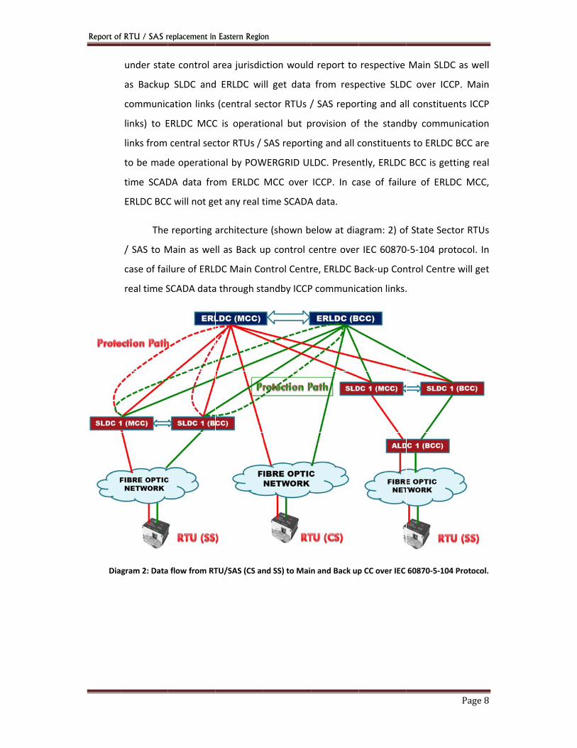
under stat
as Backup
communic
links) to E
links from
to be mad
time SCAD
ERLDC BCC
The
/ SAS to M
case of fai
real time S
agram 2: Data
replacement in
te control a
p SLDC and
cation links
ERLDC MCC
central sec
de operatio
DA data fro
C will not ge
e reporting a
Main as we
lure of ERL
SCADA data
a flow from RT
n Eastern Regio
area jurisdic
d ERLDC wi
(central se
C is operati
ctor RTUs /
nal by POW
om ERLDC
et any real t
architecture
ll as Back u
DC Main Co
a through st
TU/SAS (CS an
on ction would
ll get data
ector RTUs /
ional but p
SAS reporti
WERGRID UL
MCC over
time SCADA
e (shown b
up control c
ontrol Centr
tandby ICCP
nd SS) to Mai
d report to
from resp
/ SAS repor
provision of
ing and all c
LDC. Presen
ICCP. In ca
A data.
elow at dia
centre over
re, ERLDC B
P communic
n and Back up
respective
pective SLD
rting and al
f the stand
constituent
ntly, ERLDC
ase of failu
agram: 2) of
r IEC 60870
Back-up Con
cation links.
p CC over IEC
Main SLDC
C over ICC
l constituen
by commu
s to ERLDC
BCC is gett
ure of ERLD
f State Sect
-5-104 prot
ntrol Centre
.
60870-5-104
Page 8
C as well
P. Main
nts ICCP
nication
BCC are
ting real
DC MCC,
tor RTUs
tocol. In
e will get
Protocol.
Report of RTU / SAS replacement in Eastern Region
Page 9
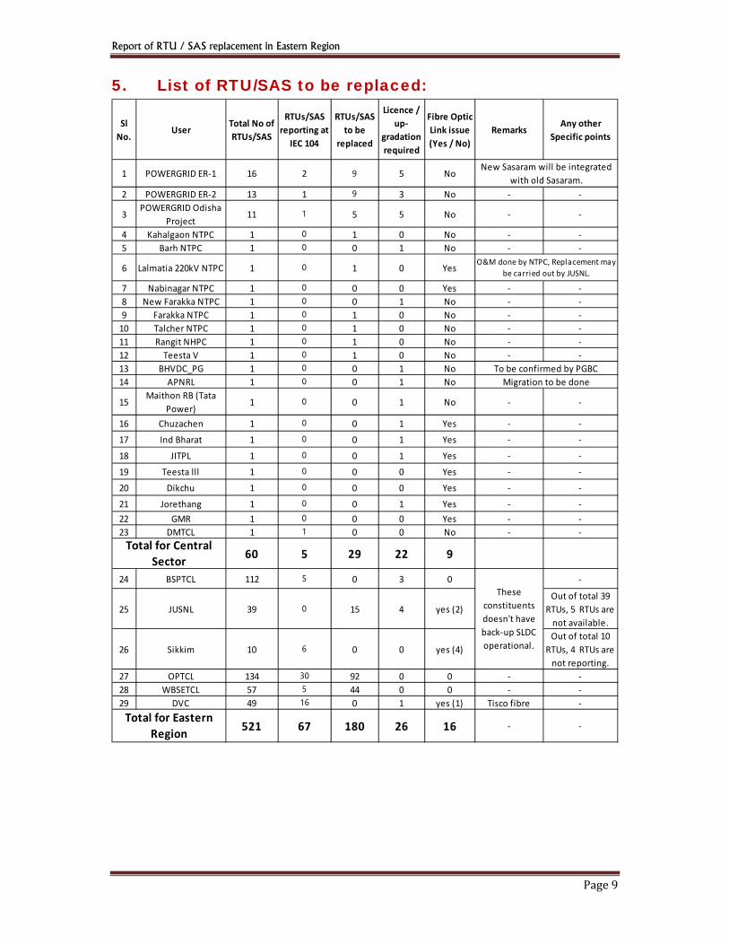
5. List of RTU/SAS to be replaced:
Sl No. User Total No of
RTUs/SAS
RTUs/SAS reporting at
IEC 104
RTUs/SAS to be
replaced
Licence / up-
gradation required
Fibre Optic Link issue (Yes / No)
Remarks Any other Specific points
1 POWERGRID ER-1 16 2 9 5 No
2 POWERGRID ER-2 13 1 9 3 No - -
3 POWERGRID Odisha Project 11 1 5 5 No - -
4 Kahalgaon NTPC 1 0 1 0 No - -5 Barh NTPC 1 0 0 1 No - -
6 Lalmatia 220kV NTPC 1 0 1 0 Yes
7 Nabinagar NTPC 1 0 0 0 Yes - -8 New Farakka NTPC 1 0 0 1 No - -9 Farakka NTPC 1 0 1 0 No - -
10 Talcher NTPC 1 0 1 0 No - -11 Rangit NHPC 1 0 1 0 No - -12 Teesta V 1 0 1 0 No - -13 BHVDC_PG 1 0 0 1 No14 APNRL 1 0 0 1 No
15 Maithon RB (Tata Power) 1 0 0 1 No - -
16 Chuzachen 1 0 0 1 Yes - -17 Ind Bharat 1 0 0 1 Yes - -18 JITPL 1 0 0 1 Yes - -19 Teesta lll 1 0 0 0 Yes - -20 Dikchu 1 0 0 0 Yes - -21 Jorethang 1 0 0 1 Yes - -22 GMR 1 0 0 0 Yes - -23 DMTCL 1 1 0 0 No - -
60 5 29 22 9
24 BSPTCL 112 5 0 3 0 -
25 JUSNL 39 0 15 4 yes (2)Out of total 39
RTUs, 5 RTUs are not available.
26 Sikkim 10 6 0 0 yes (4)Out of total 10
RTUs, 4 RTUs are not reporting.
27 OPTCL 134 30 92 0 0 - -28 WBSETCL 57 5 44 0 0 - -29 DVC 49 16 0 1 yes (1) Tisco fibre -
521 67 180 26 16 - -
These constituents doesn't have back-up SLDC operational.
Total for Central Sector
Total for Eastern Region
O&M done by NTPC, Replacement may be carried out by JUSNL.
New Sasaram will be integrated with old Sasaram.
To be confirmed by PGBCMigration to be done
Report of RTU / SAS replacement in Eastern Region
Page 10
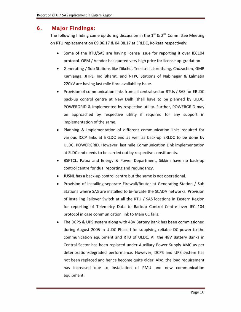
6. Major Findings: The following finding came up during discussion in the 1st & 2nd Committee Meeting
on RTU replacement on 09.06.17 & 04.08.17 at ERLDC, Kolkata respectively:
Some of the RTU/SAS are having license issue for reporting it over IEC104
protocol. OEM / Vendor has quoted very high price for license up-gradation.
Generating / Sub Stations like Dikchu, Teesta-III, Jorethang, Chuzachen, GMR
Kamlanga, JITPL, Ind Bharat, and NTPC Stations of Nabinagar & Lalmatia
220kV are having last mile fibre availability issue.
Provision of communication links from all central sector RTUs / SAS for ERLDC
back-up control centre at New Delhi shall have to be planned by ULDC,
POWERGRID & implemented by respective utility. Further, POWERGRID may
be approached by respective utility if required for any support in
implementation of the same.
Planning & Implementation of different communication links required for
various ICCP links at ERLDC end as well as back-up ERLDC to be done by
ULDC, POWERGRID. However, last mile Communication Link implementation
at SLDC end needs to be carried out by respective constituents.
BSPTCL, Patna and Energy & Power Department, Sikkim have no back-up
control centre for dual reporting and redundancy.
JUSNL has a back-up control centre but the same is not operational.
Provision of installing separate Firewall/Router at Generating Station / Sub
Stations where SAS are installed to bi-furcate the SCADA networks. Provision
of installing Failover Switch at all the RTU / SAS locations in Eastern Region
for reporting of Telemetry Data to Backup Control Centre over IEC 104
protocol in case communication link to Main CC fails.
The DCPS & UPS system along with 48V Battery Bank has been commissioned
during August 2005 in ULDC Phase-I for supplying reliable DC power to the
communication equipment and RTU of ULDC. All the 48V Battery Banks in
Central Sector has been replaced under Auxiliary Power Supply AMC as per
deterioration/degraded performance. However, DCPS and UPS system has
not been replaced and hence become quite older. Also, the load requirement
has increased due to installation of PMU and new communication
equipment.

Report of RTU / SAS replacement in Eastern Region
Page 11
Hence, POWERGRID has requested for replacement of Auxilliary Power
System (UPS & DCPS) as listed below:
Sr. No.
Location Item Make
1 Durgapur UPS AROS, Italy 2 RSCC, Kolkata
DCPS
ASCOM
3 CPCC, Durgapur 4 Kanchanpur 5 Barkot 6 Jamui 7 Maldah 8 Siliguri 400 kV 9 Jamshedpur 400 kV
10 Siliguri 220 kV 11 Rengali 12 Birpara 13 Rourkela 14 Purnea 220 kV 15 Indravati 16 Muzaffarpur 400 kV17 Biharsharif 400 kV18 Sasaram HVDC
As intimated by POWERGRID, attenuation losses in OPGW links, as listed below, has increased with time and the equipment are running on marginal levels and the communication links may work with errors or may go completely down in coming years. The location of communication equipment is not envisaged in repeater locations in some of these links, but communication equipment has been placed in repeaters as links are not working without repeater due to heavy losses in fiber. POWERGRID has requested for strengthening of OPGW work in the following lines: -
Rourkela- Talcher Durgapur- Jamshedpur Durgapur- Farakka Biharsharif- Sasaram Biharsharif- Kahalgaon LILO portion of Biharsharif-Balia at Ara
7. Conclusion & Recommendation:
India had witnessed two massive grid disturbances on 30th & 31st July 2012 wherein
major parts of Northern, Eastern & North-Eastern Regional affected. Subsequently, it was
emphasized to create a back-up control centre at a different location as recommended by
Intelligence Bureau while carried out network & physical security audit at NLDC during

Report of RTU / SAS replacement in Eastern Region
Page 12
September 2012. As per the recommendation of IB, the SCADA/EMS up-
gradation/replacement project was designed for setting up backup control centres at
different locations and dual reporting of RTU/SAS as well as various ICCP links to MCC and
BCC over IEC 104 protocol. The setting up of backup control centres of ERLDC, WBSETCL,
DVC & Odisha could be completed but dual reporting of RTUs / SAS to backup control centre
over 104 protocol and different ICCP communication links to ERLDC BCC could not be
achieved due to lack of fibre optics communication network in Eastern Region but now, the
fibre optics communication network in Eastern Region have come to a better shape and
therefore the reporting of RTUs / SAS to backup control centre also over 104 protocol can
be implemented. Provision of different ICCP communication links to ERLDC BCC may also be
made available by ULDC POWERGRID.
Total 60 numbers of RTU/SAS are installed in Eastern region for Central Sector. As per the
table above it is seen that: - i) Data reporting over IEC104 protocol could not be made
possible for 29 numbers of RTU/SAS. ii) License/software/hardware up-gradation required
for 22 numbers of RTU/SAS iii) No fibre optics cable for 09 RTU/SAS location in ER.
Total 401 numbers of RTU/SAS are installed in Eastern region for State sector. As per the
table above it is seen that: - i) Data reporting over IEC104 protocol is not possible for 151
numbers of RTU/SAS. ii) License/software/hardware up-gradation required for 8 numbers of
RTU/SAS iii) No fibre optics cable for 07 RTU/SAS location in ER.
BSPTCL, Patna and Energy & Power Department, Sikkim have no back-up control centre
(BCC). JUSNL have backup control centre but it is not operational. Without BCC dual
reporting as well as redundancy is not possible.
As requested by POWERGRID, the UPS & DCPS is required to be replaced since the
performance of these has also deteriorated.
As requested by POWERGRID, the above communication links as mentioned in para 6 above
under major findings needs to be replaced since the performance of these has deteriorated
a lot. In order to have smooth functionality & longer life period of fibre communication
links, it is suggested to carry out maintenance activities, for examples: joint box
connectivity, FODP terminal box, tracing, span damages etc. on regular basis.

Report of RTU / SAS replacement in Eastern Region
Page 13
As discussed in 1st & 2nd committee meeting for RTU replacement held at ERLDC, Kolkata on
09.06.17 & 04.08.17 respectively, specification for the RTU/SAS has been finalized and
attached at Annexure – II, the same is also available in www.erldc.org website.
Recommendation:
The committee is of the opinion as follows: -
i) It is recommended that in central sector RTU/SAS, 29 nos of RTU shall be
replaced, up-gradation required for 22 nos of RTU/SAS and in 09 RTU locations
fibre optics shall be strengthened.
ii) It is also recommended that in state sector RTU/SAS, 151 nos of RTU shall be
replaced, up-gradation required for 08 nos of RTU and in 07 RTU locations fibre
optics shall be strengthen.
iii) It is further recommended that at all SAS stations, a Firewall/Router may be
installed so that the SCADA networks should be bifurcated.
iv) It is seen that backup control centre for BSPTCL, Patna and Energy & Power
Department, Sikkim are not functional so it is recommended that BSPTCL & SMC
management should take proper action in this regard such that backup control
centre for BSPTCL & Energy & Power Department, Sikkim would be functional.
v) It is also seen that backup control centre of JUSNL is available at Namkum, Ranchi
which is presently not operational. So, it is recommended that JUSNL
management should take proper action in this regard so that the same could be
made operational.
vi) It is recommended that ULDC, POWERGRID may take necessary action for
planning of communication links for central sector RTUs as well as various ICCP
links at ERLDC backup control centre in Eastern Region & implemented by the
respective utility. Further, POWERGRID may be approached by respective utility
(if required) for any support in implementation of the same.
vii) It is seen that last mile fibre is not available from Generating / Sub Stations like
Dikchu, Teesta-III, Jorethang, Chuzachen, GMR Kamlanga, JITPL, Ind Bharat, NTPC
Stations of Nabinagar, Lalmatia 220kV. So, it is recommended that the concern
utility should take necessary action in this regard so the optical fibre from these
plants could available from plant to nearest POWERGRID sub stations. It is also to

Report of RTU / SAS replacement in Eastern Region
Page 14
be mentioned here that PMU under URTDSM project & AGC could not be
installed / made operational in absence of last mile fibre connectivity.
It is observed that new Generation are coming up without having last mile
connectivity up to the pooling stations causing problem in extending real time
SCADA data over 104 protocols, installing the PMU under URTDSM project &
operationalization of AGC. So, it is also recommended that the respective utility
may take up implementation of OPGW/ Fiber connectivity along with terminal
equipment to the nearest POWERGRID WIDEBAND sub-station. Alternately, the
respective utility may approach POWERGRID well in advance to include provision
of installing the OPGW along with terminal equipment in the connection
agreement itself for providing the last mile.
viii) It is also recommended that replacement of Auxiliary Power System (UPS &
DCPS) is required in some identified stations under POWERGRID ER jurisdiction
as mentioned in para 6 above under major findings.
ix) Considering smooth functioning of Communication links, it is proposed to lay
new OPGW on the above links as mentioned in para 6 above under major
findings. It is also suggested to maintain all the fibre communication links on
periodic basis for smooth operation of OPGW communication links.
:: xx ::
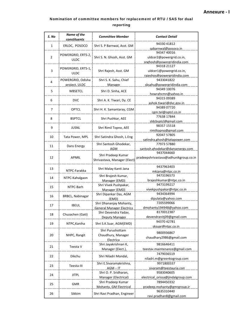
Annexure - I
S. No Name of the constituents
Committee Member Contact Detail
1 ERLDC, POSOCO Shri S. P Barnwal, Asst. GM 94330 [email protected]
2 POWERGRID, ERTS-2, ULDC Shri S. N. Ghosh, Asst. GM
94347 [email protected],
3 POWERGRID, ERTS-1, ULDC Shri Rajesh, Asst. GM
94318 [email protected],
4 POWERGRID, Odisha project, ULDC
Shri S. K. Sahu, Chief Manager
5 WBSETCL Shri D. Sinha, ACE 94349 [email protected]
6 DVC Shri A. K. Tiwari, Dy. CE 94315 [email protected]
7 OPTCL Shri H. K. Samantaray, CGM 94389 [email protected]
8 BSPTCL Shri Pushkar, AEE 77638 [email protected]
9 JUSNL Shri Rimil Topno, AEE 98357 [email protected]
10 Tata Power, MPL Shri Satindra Ghosh, L.Eng 92047 [email protected]
11 Dans Energy Shri Santosh Ghodekar, AGM
77973 [email protected]
12 APNRL Shri Pradeep Kumar Shrivastava, Manager (Elect)
13 NTPC-Farakka Shri Malay Kanti Jana [email protected]
14 NTPC-Kahalgaon Shri Brajesh Kumar, Manager (EMD)
15 NTPC-Barh Shri Vivek Pushpakar, Manager (EMD)
16 BRBCL, Nabinagar Shri Dipankar Das, AGM (EMD)
17 IBEUL Shri Dhananjay Mohanty, General Manager Electrica
18 Chuzachen (Gati) Shri Devendra Yadav, Deputy Manager
19 NTPC,Kaniha Shri S.K.Suar, AGM(EMD) 94370 [email protected]
20 NHPC, RangitShri Purushottam
Chaudhury, Manager Electrical
21 Teesta V Shri Jayakrishnan K, Manager (Elect.),
22 Dikchu Shri Niladri Mondal, [email protected]
23 Teesta-III Shri E.Sivaramakrishna,AGM – IT
9971800337 [email protected]
24 JITPL Shri O. P. Sridharan, Manager (Electrical)
25 GMR Shri Pradeep Kumar Mohanty, GM Electrical
26 Sikkim Shri Ravi Pradhan, Engineer [email protected]
Nomination of committee members for replacement of RTU / SAS for dual reporting

Annexure – II
TECHNICAL SPECIFICATION OF RTU

Contents Section 1: TECHNICAL SPECIFICATION OF RTU ...................................................................................... 4
1.0 General ....................................................................................................................................... 4 1.1 Design Standards ........................................................................................................................ 5 1.2 RTU Functions ............................................................................................................................ 5 1.3 Communication ports ................................................................................................................. 5 1.4 Modems ..................................................................................................................................... 6 1.5 Splitters ...................................................................................................................................... 7 1.6 Local Configuration & Maintenance Interface ............................................................................ 7 1.7 Local Data Monitoring System (LDMS) Interface......................................................................... 7 1.8 Communication interface between RTU & MFMs ....................................................................... 8 1.9 Communication Protocol between RTU & IEDs ........................................................................... 8 1.10 Master Station Communication Protocol ................................................................................. 8 1.10.1 Scan groups ....................................................................................................................... 9 1.10.2 Reporting of status points ................................................................................................. 9 1.10.3 Reporting of Analog points ................................................................................................ 9 1.10.4 Digital control commands .................................................................................................. 9 1.11 Data Concentrator Communication Protocol............................................................................ 9 1.12 Analog Inputs ......................................................................................................................... 10 1.13 Status Inputs .......................................................................................................................... 10 1.13.1 Contact Multiplying Relay ................................................................................................ 11
1.13.2 Momentary Change Detection ......................................................................................... 11 1.14 Digital Telemetry ................................................................................................................ 11 1.15 Sequence of Events (SOE) feature .......................................................................................... 11 1.16 Control Outputs ..................................................................................................................... 12 1.16.1 Two State Momentary Control ........................................................................................ 12 1.16.2 Raise/Lower Pulse Output ............................................................................................... 12 1.16.3 Control Output Interposing Relays (Double Contact Digital Output) ................................ 12 1.16.4 Latching (Dummy Breaker) Relay ..................................................................................... 13 1.16.5 Control Security and Safety Requirements ...................................................................... 13 1.16.6 Local/Remote selector switch .......................................................................................... 13 1.17 Time facility ............................................................................................................................ 13 1.18 Diagnostic features ................................................................................................................ 14 1.19 Input DC Power Supply ........................................................................................................... 14 1.20 Environmental Requirements ................................................................................................. 14 1.21 Noise level .............................................................................................................................. 14 1.22 RTU Size and Expandability..................................................................................................... 15 1.23 RTU and SIC panels ................................................................................................................. 15 1.24 Interconnections .................................................................................................................... 16 1.25 Wiring/Cabling requirements ................................................................................................. 16 1.26 Terminal Blocks ...................................................................................................................... 17
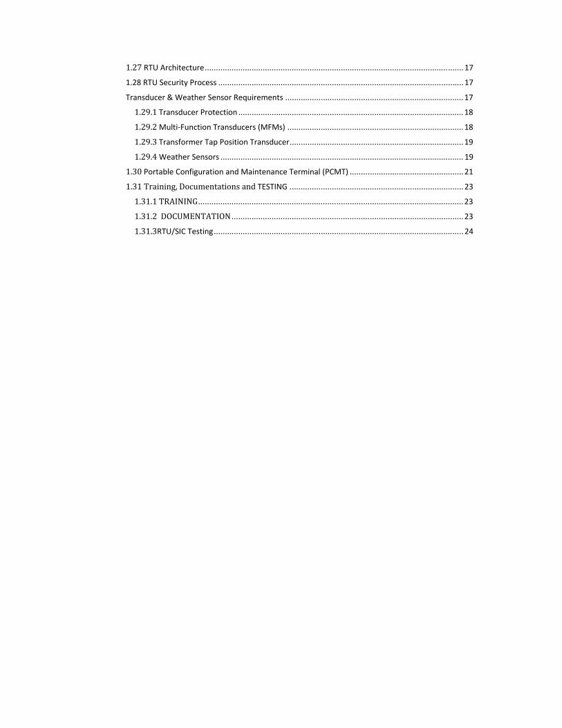
1.27 RTU Architecture .................................................................................................................... 17 1.28 RTU Security Process .............................................................................................................. 17 Transducer & Weather Sensor Requirements ................................................................................ 17 1.29.1 Transducer Protection ..................................................................................................... 18 1.29.2 Multi-Function Transducers (MFMs) ............................................................................... 18 1.29.3 Transformer Tap Position Transducer .............................................................................. 19 1.29.4 Weather Sensors ............................................................................................................. 19 1.30 Portable Configuration and Maintenance Terminal (PCMT) ................................................... 21 1.31 Training, Documentations and TESTING .............................................................................. 23 1.31.1 TRAINING ....................................................................................................................... 23 1.31.2 DOCUMENTATION ........................................................................................................ 23 1.31.3RTU/SIC Testing ................................................................................................................ 24

Section 1: TECHNICAL SPECIFICATION OF RTU
1.0 General The Remote Terminal Unit (RTU), shall be installed at Substations & Power stations to acquire analog data and device status signals. RTU shall also be used for control of station devices from Master station. The supplied RTUs shall be interfaced with the Control & Relay (C&R) panels, communication equipment, power supply distribution boards; for which all the interface cables shall be supplied by the Contractor. This document describes the specifications for the Remote Terminal Unit (RTU). Contractor shall supply RTU, associated equipment such as transducers, relays, weather sensors, modems, cabling etc. and required number of panels for housing of all the hardware envisaged for the RTU and system interface cubicle (SIC). The contractor shall be responsible for supplying all hardware, software, installation, cabling and field implementation for RTU as defined in this Specification. The contractor shall also provide complete documentation, training and testing to fully support the hardware and software provided. The RTU shall be used for real-time supervision and control of substation/ power plant through SCADA system. RTU configuration/ point count, transducer count and requirement of weather sensors quantity is given in Appendix – A.
The manufacturer’s whose RTU is being offered should have manufactured and supplied at least 50% of the tendered value at any EHV environment of 132 kV or above Substation/Power Plant and the same shall be in successful operation for more than 2 years as on the date of bid opening.
Should the Contractor elect to subcontract manufacturing, installation, testing & commissioning or any other work defined herein, it shall remain the Contractor's responsibility to complete the assigned work. It is Employer’s intent that the Contractor uses as much standard hardware and soft-ware as possible; however, all of the functional requirements of this Specification must be satisfied. The use of the Contractor's standard hardware and software may cause the Contractor to conclude that there is a need for additional items not specifically mentioned in this Specification. The Contractor shall supply all such items and provide a complete RTU design that meets all of the Employer’s functional requirements defined in this Specification. In event of the configuration of RTU given in specification undergo changes during detailed engineering, the prices of particular RTU shall also be adjusted based on the unit prices of status Input cards, analog input cards, control output cards, control output relays, CMRs and Modems only. Employer may not initially procure all capabilities specified in this document. Regardless of the RTU configuration purchased, the RTUs shall be capable of all functions specified herein with the addition of the necessary hardware and software modules in the field when required by Employer. Each function is presented in sufficient detail to provide the Contractor with as much insight as possible into both the initial and future requirements of the RTUs. The Weather Sensors to be supplied under the project shall be field proven and shall have been in successful operation for meteorological application for at least one year as on date of Bid opening. The Bidder shall furnish the documentary evidence in support of the above and submit the same along with the bid.
1.1 Design Standards The RTUs shall be designed in accordance with applicable International Electro-technical Commission (IEC), Institute of Electrical and Electronics Engineer (IEEE), American National Standards Institute (ANSI), and National Equipment Manufacturers association (NEMA) standards and British Standards, unless otherwise specified in this Technical specification. In all cases the provisions of the latest edition or revision of the applicable standards in effect shall apply.
1.2 RTU Functions All functional capability described herein shall be provided by the Contractor even if a function is not initially implemented. The term master station is used to denote the SCADA systems. As a minimum, the RTUs shall be capable of performing the following functions:
(a) Collecting and processing the digital status inputs, analog inputs, accumulated values and transmitting to master station(s)
(b) Receiving and processing digital & analog control commands from the master
station(s)
(c) Accepting polling messages from at least three master station(s) simultaneously using separate logical databases for each master station.
(d) Communication simultaneously on all Communication ports (as per cl. 1.3) and
using multiple concurrent protocols, including the IEC 60870-5-101, 60870-5-104 & MODBUS/103 protocol.
(e) Data transmission rates from 300 to 9600 baud for serial ports (for both IEC
60870-5-101 & MODBUS/103) and 10/100 Mbps for TCP/IP Ethernet ports.
(f) RTU shall be compatible with protocol 61850 for communication with IEDs.
(g) RTU shall have the capability of automatic start-up and initialisation following restoration of power after an outage without need of manual intervention. All restarts shall be reported to the connected master station(s).
(h) RTU shall support time synchronization through messages received from master
station using IEC 60870-5-101 protocol.
(i) RTU shall support downloading of RTU database from the master station using Intranet
(j) RTU shall support SOE (Sequence of events) feature
(k) Acting as a data concentrator for acquiring data from Slave RTUs and exercising
supervisory control on slave RTUs using IEC 60870-5-101 and IEC 60870-5-104 protocol.
(l) RTU shall support archiving facility for reporting and analysis. The archived data shall be saved to user defined file duration at user defined interval-eg. Every 5 minutes for a period of 1 week. The computation of the archived data shall also be supported – eg. Maximum, Minimum and Average.
1.3 Communication ports The RTUs shall support simultaneous communications with multiple independent master stations (SCADA system), maintenance and configuration terminal (Laptop PC), Multi-function transducers and Local Data Monitoring System (LDMS).

The RTUs shall have communication ports as follows:
a) Two Ethernet ports for connectivity to Master Station on IEC 60870-5-104 and to relays on IEC 61850.
b) 2 RS232 ports –for communication with master stations on IEC 60870-5-101
c) One port for the RTU maintenance and configuration terminal.
d) Two ports for Local Data Monitoring System (LDMS).
e) Required number (minimum two) of RS 485 ports for polling Multi-function
transducers using MODBUS/103 protocol in multi-drop (party line) mode. Maximum 8 nos MFMs shall be connected to each port.
It shall be possible to increase the number of communication ports in the RTU by addition of cards, if required in future. The RTU shall respond to independent scans and commands from Master Station, LDMS and Configuration & Maintenance Terminal simultaneously. The RTU shall support the use of a different communication data exchange rate (bits per second) and scanning cycle on each port.
1.4 Modems The modems can be used for RTU communicating to master station. The Contractor
shall supply two (2) number modems one at Control Centre/Stand alone and other at RTU end. For Critical RTUs, 4 nos modems are required, 2 nos. at Control Centerand 2 nos. at RTU End. The modem for remote end, complete in all respects including power supply unit & rack shall be supplied. These modems can be located either in the FEP at Control Center end or at other Communication nodes (Stand Alone Modem). The modems shall meet the following requirements:
a) Use CCITT Standards including V.24, V.28.
b) Use frequency shift keying (FSK) modulation.
c) Communicate at data rates of 300, 600 and 1200 bps.
d) Use CCITT R.38a, and R.38b standard tones for the selected RTU data rate.
e) Use PLCC bandwidth upto4khz and shall accommodate multiple data channels over and above voice channels.
f) Use both 2-wire and 4-wire communication lines.
g) Receive level adjustable from -8 to -40 dBm @ 600 ohms.
h) Transmit level adjustable from 0 to -24 dBm @ 600 ohms.
i) Have a minimum sensitivity of -48 dBm.
j) Shall operate on 48 VDC power supply
k) Compatible with IEC 101
1.5 Splitters Splitters shall be provided for splitting of 60870-5-101 protocol communication ports to communicate with two terminal servers. The splitters shall be mounted in the panel for Terminal Servers and shall operate on 24 or 48 VDC.
1.6 Local Configuration & Maintenance Interface
The RTUs shall include the interface to support the portable configuration and maintenance terminal (PCMT). The interface shall provide easy access to allow employer to use the maintenance terminal at the RTUs installed in the field using Ethernet. Local Configuration & Maintenance Interface
1.7 Local Data Monitoring System (LDMS) Interface The RTUs shall include the interface for communication with the LDMS system. The LDMS shall be used for local data acquisition, monitoring and control of substation parameters through RTU. The scope of LDMS shall include installation and integration of LDMS software on a Personal computer. The LDMS shall be a mini SCADA system providing MMI capability for use in the sub-
station control room building. The LDMS software shall include following functions:
I. data acquisition for analog, digital and pulse accumulator type data
II. data processing – Conversion to engineering units , limit monitoring, data validity test, calculated data
III. calculated data (such as maximum, minimum, average values with associated time-
stamping etc.) of all the station parameters. IV. Time Synchronization
V. Sequence of Events Processing
VI. Supervisory control
VII. Alarm, tagging, trending, quality codes etc.
VIII. Single Line Diagrams, Trends, daily, weekly, monthly reports etc. shall be prepared by the bidder and integrated on LDMS system. The LDMS shall also have capability to generate additional displays, single line diagrams, reports , and trends.
The LDMS shall store all real-time telemetered & calculated data every 5 minutes (adjustable to 15,30,45,60 minutes). The software and hardware shall be sized for storage of all above data at every 5 minutes for at least six months duration. All alarms, events, SOE etc. shall also be stored on regular basis. It shall be possible to define daily, weekly, monthly Substation reports on LDMS. It shall be possible to generate reports highlighting the maximum, minimum, average with associated time-stamping etc. of all the station parameters. The historical data stored on the storage medium shall be in standard format and necessary tools for its export to standard spreadsheet programs(Excel) shall be provided. The LDMS shall update analog data from RTU every ten seconds (programmable) and status data by exception. The SOE status data shall be recorded with resolution of 10 ms timestamp. The contractor shall provide 1 no, 2 kVA inverter of reputed make without battery. (Input from 48 VDC with -10% to 20 % variation, Output 230 V AC +/- 2% suitable for single
computer load) with each LDMS system. The contractor will use the 48 VDC power supply available in RTU. The contractor shall also provide 1 no. 1 KVA UPS of reputed make (Input: single phase 230 V with variation from 190 to 270 V, Output: single phase 230 V with +/- 1% variation with 8 hrs recharge time and suitable for single computer load) with each LDMS system.
1.8 Communication interface between RTU & MFMs The RTU shall acquire data from the MFMs. The MFMs will act as slave to the RTU. The RTU shall have the ability of issuing retry scan to acquire data from the MFMs in case of communication failure between RTU and MFMs. All data from the devices connected on a single port shall be acquired within 5 seconds.
1.9 Communication Protocol between RTU & IEDs The RTU shall use the IEC 61850 protocol for communication with IEDs over Sub-station LAN. The RTU shall act as a Client and collect data from the IEDs). The RTU shall store the data acquired from the MFMs & IEDs in its database and do processing like change detection/deadband processing on the data for optimizing its transmission to the Master Station (SCADA Control Centre). The processing shall include requirements of mapping of information from the protocol of MFM/IEDs to the protocol requirement for communication with Control Center.
1.10 Master Station Communication Protocol The Contractor shall provide a communication protocol for communicating with SCADA master stations using the IEC 60870-5-101 and IEC 60870-5-104communication protocol standard. The communication protocol shall support all the requirements of this standard. The communication protocol shall be non-proprietary and the Contractor shall provide complete description and documentation of the protocol to Owner. The RTU shall perform as a slave to SCADA master station when using the IEC 60870-5-101 protocol. All communication shall be initiated by the SCADA master stations. RTU must notify the master stations of unusual conditions at the RTU (such as a power fail/restoration or RTU malfunction), the transfer of changed data etc. All the notifications shall be accomplished within the framework of the periodic data acquisition exchanges. The RTU shall process the various messages/commands for communication to the Master station using the following priority.
a) Control command
b) Status data by exception
c) Analog data by exception
d) Analog data periodic
e) Status data integrity scan The communication interface to the master station(s) shall allow scanning and control of

defined points within the RTU independently for each master station using a separate logical database in the RTU. It shall be possible to pick points from the RTU database randomly and assign it for reporting to a Master station. Further, the RTU shall support the use of a different communication data exchange rate (bits per second), scanning cycle, and/or communication protocol to each master station.
1.10.1 Scan groups Analog and digital input points (including points reported by exception) shall be assignable to scan groups using the IEC 60870-5-101and IEC 60870-5-104 protocol profile communication protocol standard. A scan group shall be a specified set of data points within the RTU central database which will be communicated to a master station when requested by a specific (addressed) scan request. A scan group size shall only be limited by the communication protocol message length. Any RTU input point shall be assignable to any scan group. The RTUs shall support at least sixteen scan groups and all scan groups per communication port (i.e. master station/ LDMS interface). The Contractor shall provide a convenient and flexible scheme for assigning points in the RTU to scan groups.
1.10.2 Reporting of status points The RTU communication protocol shall be configured to report digital status changes by exception to master station using the IEC 60870-5-101 and IEC 60870-5-104 protocol profile communication protocol standard. Digital status data shall have higher priority than the Analog data. All the digital status data shall also be assigned to scan groups for integrity check by Master stations at every 10 minutes.
1.10.3 Reporting of Analog points The analog data shall be reported periodically to update all the values at the master station within 10 to 15 seconds using IEC 101 /104 protocol profile . Analog data shall also be reported by exception if the analog value exceeds its previous value by more than 20%.
1.10.4 Digital control commands The RTU shall follow the select-and-execute sequence for operation of digital control commands from the master station using the IEC 60870-5-101 and IEC 60870-5-104 protocol profile communication protocol standard. The RTU shall reset its control logic upon any error in the sequence.
1.11 Data Concentrator Communication Protocol The RTU shall act as a IEC 60870-5-101 and IEC 60870-5-104 protocol master and collect data and also perform supervisory control from/on the slave RTUs and communicate it to the Control Center. The Master protocol implementation shall be such that the data polling requirements mentioned at section 1.10 is at least accomplished. RTU as a Data concentrator shall be provided with at least ten (10) IEC 101 input ports/ cards and shall have capability to report to two master stations on IEC 104 interface. Data concentrator shall support at least 1,500 (fifteen hundred) data points. The RTU as a Data Concentrator shall be supplied with GPS receiver system with antenna, cable etc. for time stamping of Data concentrator which in turn shall synchronize the IEC 101 protocol

connected RTU/device. The RTU as a Data Concentrator shall come complete with built in monitoring mechanism to avoid loss of any data, especially the one reported by exception. The data concentrator shall have dual CPU and dual Power supply unit. The overall data update requirement from any Sub-RTU to Control centre should not affect the functionality defined elsewhere in the specification. The Data concentrator shall have the provision for remote login from Control centre. The SLDC computer system shall be able to configure and poll health of Data concentrator from remote on 104 connected interface after due authentication of the users. It shall support diagnostic & maintenance activities remotely. Individual RTU configuration shall be possible from Data Concentrator including accommodating devices from heterogeneous suppliers. The RTU as a Data Concentrator shall have following communication ports & support for protocols:
i. IEC104 for SCADA control centers. ii. IEC101 for Sub-RTUs. iii. IEC 101/104 for local SCADA
The other requirements given for RTU elsewhere in the specification shall be applicable to RTU as a Data concentrator also
1.12 Analog Inputs The RTU shall accommodate analog inputs which are unipolar or bipolar, 2-wire ungrounded differential signals. RTU shall be capable of accepting other standard analog input ranges (0 to 5V, 0 to 10mA, +/- 10 mA, 4-20 mA). The RTU shall make all appropriate signal level conversion and conditioning to allow full utilization of analog inputs and meaningful reasonability checking. The analog-to-digital converter shall have a minimum resolution of 2048 counts (sign plus 11 data bits). Each type of analog input shall be converted with full resolution. The RTU shall monitor the drift in characteristics of its ADC and mark the analog points with a drift quality code if a drift is detected. This drift quality code shall be sent to the master station also. The RTU accuracy, for analog input measurement, shall be 99.8% or better at 25 degree C ambient temperature. Mean accuracy shall drift no more than 0.002% per degree C within the temperature range of –5 to +55 degree C. Determination of accuracy shall be made while the analog multiplexer is operating at rated speed. Each input shall have suitable protection and filtering to provide protection against voltage spikes and residual current at 50 Hz, 0.1 ma (peak-to-peak) and overload. Loading upto 150% of the input value shall not sustain any failures to the RTU input. The total input impedance offered by the RTU shall not be greater than 250Ω (for +4 to +20 mA range). All analog inputs shall be scanned by the RTU from the field at least at 1 second periodicity.
1.13 Status Inputs RTU shall be capable of accepting isolated dry (potential free) contact status inputs. The RTU shall provide necessary sensing voltage, current, optical isolation and de-bounce filtering independently for each status input. The sensing voltage shall not exceed 48 Vdc. The sensing voltage source shall be isolated from that of the RTUs logic power so that any noise or a short circuit across the sensing supply of a digital status input terminals would not disrupt the RTU operation other than the shorted digital status input.

The RTU shall be set to capture contact operations of 20 ms or more duration. Operationsof less than 20 ms duration shall be considered no change (contact bounce condition). The RTU shall accept two types of status inputs i.e. Single point Status inputs and Double point status inputs. Single point status input will be from a normally-open (NO) or normally-closed (NC) contact which is represented by 1-bit in the protocol message. Double point status input will be from two complementary contacts (one NO and one NC) which is represented by 2-bits in the protocol message. A switching device status is valid only when one contact is closed and the other contact is open. Invalid states shall be reported when both contacts are open or both contacts are closed. All status inputs shall be scanned by the RTU from the field at 1 millisecond periodicity.
1.13.1 Contact Multiplying Relay Contact multiplying relays (CMRs) are required to multiply the auxiliary contacts of breaker/isolators etc. The contacts of these relays shall be used to provide status input to the RTUs. The relays shall be of self-reset type. The relay shall have a minimum of two changeover contacts each with minimum current carrying capacity of 5 A at 110V/220 V DC. The relays shall conform to the following requirements:
a) Power frequency withstand voltage: 2 kV for 1 minute as per IEC standards.
b) Insulation resistance of 100 Mohms at 500 V DC.
c) 5 KV Impulse test as per IEC standards The CMRs shall be generally mounted in existing control & Relay panel but in case of non-availability of space, it shall be accommodated in the System Interface Cabinets (being supplied by the Contractor).
1.13.2 Momentary Change Detection Two-state status input points with momentary change detection shall be used by Employer for points where multiple operations (changes of state) can occur between scans from the master station (such as breakers with auto-reclosing devices that operate faster than the master station scan rate). The RTU shall capture and maintain all of the momentary changes, up to 4 per MCD digital status point. The MCD status input points shall be set to capture operations of greater than 20 ms duration. Alternatively, the RTU can store and report the multiple state changes of a digital input as discrete events. It shall be ensured that all the changes are reported to the Master station in the sequence in which they occur in the RTU.
1.14 Digital Telemetry
Digital telemetry input points shall be provided for sixteen bit inputs from employer telemetry contacts. The digital telemetry may use BCD, (4 bit decimal character without sign) and/or binary (16 bit) codes.
1.15 Sequence of Events (SOE) feature

SOE is the time-stamped digital status data. SOEs will enable Employer's personnel to determine the sequential operation of digital status input devices for their state changes. The RTU shall time-stamp the digital status data with a time resolution of one millisecond. Initially, all breakers & protection contacts digital status input points in the RTU shall be configured as SOE points. However it shall be possible to assign any digital status input data point in the RTU as SOE point. Each time a SOE status input point changes state, the RTU shall time-tag the change and send it to the Master station. The RTU shall maintain a SOE buffer within the RTU for communication delays and communication failure. SOE buffer shall be sized to store, as a minimum, of 1024 events. The RTU shall transmit the SOE data stored in its buffer to master station. An acknowledgement of receipt by the master station shall be made prior to the loss of any data in the RTU SOE buffer. Data not received at the master station shall be retransmitted. The RTU shall send a message to the master station to indicate the RTU SOE data buffer overflow condition.
1.16 Control Outputs The RTU shall provide the capability for a master station to select and change the state of digital output points. Device control will be used by employer to control power system devices including:
(a) Two-state Devices: Circuit breakers, motor-operated switches, auto/mannual switches, relay disable/enable, and other two-state devices
(b) Variable Output Devices: Raise/lower control of generators, transformer load-tap-
changers (LTC), and other variable output devices.
The RTUs shall have the capability for control outputs as described in the following sections
1.16.1 Two State Momentary Control A pair of outputs shall be supplied for each two-state (open/close) control output point that drive control relays. One output shall be supplied for open, the other for close. Upon command from a master station using the check-before-execute sequence, the appropriate control output shall be operated for a preset (momentary) time period. The operation period shall be adjustable for each point from 0.1 to 2 seconds.
1.16.2 Raise/Lower Pulse Output A pair of outputs shall be supplied for each (raise/lower) control output point that drive control relays. One output shall be supplied for raise, the other for lower. When commanded from the master station, the appropriate raise or lower output shall be operated for the selected time interval. The closure time interval for raise/lower pulse output points shall be specified in the operate command from the master station. The raise/lower output for each point shall operate over a range of 0.1 to 4 seconds in a minimum of eight equal increments.
1.16.3 Control Output Interposing Relays (Double Contact Digital Output)

Control output interposing relays shall be supplied by the Contractor for each control output specified in appendix. Each control relay shall consist of two isolated single-poledouble-throw contacts. The output contacts shall be rated to carry minimum current of 10 amps at 220 V DC, and shall provide arc suppression to permit interruptions of an inductive load. Relay coils shall be shunted with diodes to suppress inductive transients associated with energizing and de-energizing of the relay coils. The relays shall conform to the IEC standards.
1.16.4 Latching (Dummy Breaker) Relay The Contractor shall provide a latching relay to be used to simulate and test supervisory control from the RTU. The simulation relay shall accept the control signals to open and close from the RTU, and shall provide the correct indication response through a single contact indication input point. This point is not included in the RTU point count in Appendix A.
1.16.5 Control Security and Safety Requirements The RTU shall include the following security and safety features as a minimum for control outputs:
(a) Select-and-execute sequence for control output.
(b) No more than one control point shall be selected at any given time.
(c) The control selection shall be automatically cancelled if after receiving the "control selection" message, the "control execute" command is not received within the set time period.
(d) The control selection shall be automatically cancelled if after receiving the "control
selection" message, the "operate" command is not the next received message and is not received within the set time period.
(e) No control command shall be generated during power up or power down of RTU.
1.16.6 Local/Remote selector switch A manual Local/Remote selector switch shall be provided for each RTU to disable all control outputs by breaking the power supply connection to the control outputs. When in the "Local" position, the Local/Remote switch shall allow testing of all the control outputs of RTU without activating the control outputs to field devices. A status input indication shall be provided for the Local/Remote switch to allow the SCADA system to monitor the position of the switch. This point is not included in the RTU point count defined in Appendix A.
1.17 Time facility The RTU shall have an internal clock with the stability as defined in Table-1. The RTU shall be synchronised through synchronisation message from master station at every 10 minutes using IEC 60870-5-101 protocol. The RTU shall support the calculation of the propagation delay dynamically by the Master station. However, all the RTUs shall have a suitable interface for receiving synchronization signals from a local GPS receiver. The RTUs communicating over IEC-60870-5-104 shall be supplied with a GPS receiver for synchronization of RTU clock.
The RTU shall synchronize its internal clock with the master station system clock when time synchronization messages are available and shall mark all the time stamped information/data as invalid when the RTU clock is not synchronised with the Master station. To achieve the RTU internal clock stability of atleast 1 ppm, the contractor shall supply RTUs with GPS. The internal GPS should also provide positional information for asset management.
1.18 Diagnostic features The RTU design shall facilitate isolation and correction of all failures. The following features which promote rapid problem isolation and replacement of failed components shall be provided:
a) Self-diagnostic capabilities within each RTU which can be initiated at the RTU site. The diagnostic software shall check for memory, processor, and input/output ports errors and failures of other functional areas defined in the specification of the RTU.
b) On-line error detection capabilities within the RTU and detailed reporting to the
connected master station of detected errors. It shall be possible to choose the errors to be sent to the Master station within the framework of the communication protocol.
c) Local indication of major RTU failures
d) A non-volatile event buffer that shall record all fatal errors/restarts/ faults. The RTU
should archive the events on an External Storage device.
e) RTU should support SNMPv3 and Syslog.
f) RTU should have a inbuilt Web Browser application which can be accessed over Intranet from the Control Centre.
1.19 Input DC Power Supply The RTU will be powered from a 48 V DC (+ve earthed) system. The RTU shall not place additional ground on the input power source. The characteristics of the input DC power supply shall be
(a) Nominal voltage of 48 Vdc with operation between 36 and 72 Vdc.
(b) Maximum AC component of frequency equal to or greater than 100 Hz and 0.012 times the rated voltage peak-to-peak.
The RTU shall have adequate protection against reversed polarity, over current and under voltage conditions, to prevent the RTU internal logic from being damaged and becoming unstable causing mal-operation.
1.20 Environmental Requirements The RTU will be installed in control room buildings with no temperature or humidity control. The RTUs shall be capable of operating in ambient temperature from -5 to +55 degree C with rate of temperature change of 20 degree C/hour and relative humidity less than 95%, non-condensing. At some locations, environmental temperature may go below –5 degree C for which the contractor shall ta ke suitable measures for successfuloperation of RTU.
1.21 Noise level

RTU shall be solid state and acoustically quiet. The audible noise generated by the RTU equipment shall not exceed 50 dbA one meter from the enclosure.
1.22 RTU Size and Expandability The software and the database shall be sized to accommodate growth within the ultimate sizing parameters as defined in this specification for the RTU without requiring software or database structure regeneration. The point counts for the RTUs have been defined in the Appendix A. The RTU shall have additional wired available reserve capacity of twenty percent (20%) for each type of points defined in the BOQ. This reserve capacity shall be used without any additional hardware such as I/O cards and terminal blocks. The RTUs delivered shall have the capability to accommodate additional I/O modules to expand the overall point count of the RTU by a minimum of fifty percent (50%) i.e. 80% more than the actual RTU count defined in the BOQ. The I/O modules here means Status Input module, Analog input module and the Control output module. Other modules, such as processor module, racks etc. as required to meet the overall expandability requirement defined above shall also be supplied by the contractor.
1.23 RTU and SIC panels The Contractor shall provide RTU & System Interface Cabinet (SIC) panels. The SIC shall primarily house all MFMs, interposing control relays and interface terminal blocks. Generally, CMRs and MFMs shall be installed in the Customer Control/Relay panels and all other equipments like Heavy Duty Relays etc shall be housed in the RTU panel. However where it would not be possible to mount the MFMs in the existing customer panel SIC panel shall be provided. The SIC shall be mounted adjacent to the RTU panel. However, in a few cases, the SIC may be mounted separately at a different locations. All RTU signals shall be connected to the MFMs, interposing relays, and field signals in the interface cabinet. The panels shall meet the following requirements:
(a) Shall be free-standing, floor mounted and height shall not exceed 2100 mm.
(b) Shall have maintenance access to the hardware and wiring through lock-able full height doors.
(c) Shall have the provisions for bottom cable entry
(d) The safety ground shall be isolated from the signal ground and shall be connected to
the ground network. Safety ground shall be a copper bus bar. The contractor shall connect the panel’s safety ground of to the Employer’s grounding network. Signal ground shall be connected to the communication equipment signal ground.
(e) All panels shall be supplied with 230 Vac, 50 Hz, single-phase switch and 15/5A duplex socket arrangement for maintenance.
(f) All panels shall be provided with an internal maintenance lamp, space heaters
and gaskets.
(g) All panels shall be indoor, dust-proof with rodent protection, and meet IP41 class of protection.

(h) There shall be no sharp corners or edges. All edges shall be rounded to prevent injury.
(i) Document Holder shall be provided inside the cabinet to keep test report, drawing,
maintenance register etc.
(j) All materials used in the enclosures including cable insulation or sheathing, wire troughs, terminal blocks, and enclosure trim shall be made of flame retardant material and shall not produce toxic gasses under fire conditions.
(k) The structural frame of the panels shall be of cold rolled sheet steel of thickness not
less than 3 mm for the weight bearing members of the panels such as base frame, front sheet & door frames and 2mm for sides, door, top and bottom portions.
(l) All sheet steel work shall be degreased, pickled, phosphated in accordance with
IS6005. The phosphate coating shall be sealed with application of two coats of ready mixed, stoving type zinc chromate primer. Two coats of synthetic enamel paint RAL7032 shade) shall be applied both in the exterior and the interior of the panel.
1.24 Interconnections All cabling between component units of the RTU, RTU to interface cabinet, RTU to MFMs and to the Employer control and relay panels (located in the substation control room) shall be supplied and installed by the Contractor and shall be shown on Contractor supplied drawings. Plug-type connectors with captive fasteners or compression type connectors shall be used for all internal interconnections. The connectors shall be polarized to prevent improper assembly. Each end of intercon-nection cables shall be identified by a marker which includes the cable number and the identifying number and location of each of the cable's terminations. This information shall match with the Contractor's drawings. Adequate space and hardware shall be provided for routing of the field wiring within the enclosures. Contractor wiring within enclosures shall be neatly arranged and shall not be directly fastened to the enclosure frame. All internal interconnection wiring and cables shall be routed separately from field wiring to the RTU terminals & power wiring. All wiring shall use copper conductors and have flame retardant insulation. Conductors in multi-conductor cables shall be individually colour coded. The use of non-flammable, self-extinguishing, plastic wire troughs is permissible. Metal clamps must have insulating inserts between the clamps and the wiring. Wiring between stationary and movable components, such as wiring across door hinges or to components mounted on extension slides, shall allow for full movement of the component without binding or chafing of the wiring.
1.25 Wiring/Cabling requirements Shielded (screened) cables shall be used for external Cabling from the RTU/ SIC panels. These external cables (except communication cables) shall have the followingcharacteristics:
a) All cables shall have stranded copper conductor.
b) Minimum core cross-section of 2.5 mm2 for PT cables, 4/2,5 mm
2 for CT cables or as
per site requirements and 2.5 mm2 for Power & Control outputs and 1.5mm
2 for
Digital Status inputs, transducer mA current output c) Rated voltage Uo/U of 0.6/1.1KV

d) External sheathing of cable shall have oxygen index not less than 29 & temperature index not less than 250. Cable sheath shall meet fire resistance test as per IS 1554 Part- I.
e) Shielding, longitudinally laid with overlap.
f) Dielectric withstand 2.5 kV at 50 Hz for 5 minutes
g) External marking with manufacture's name, type, core quantity, cross-section, and year
of manufacture. h) The Communication cable shall be of shielded, twisted pairs and of minimum 0.22sq
mm size
1.26 Terminal Blocks Terminal blocks shall be having provision for disconnection (isolation), with full-depth insulating barriers made from moulded self-extinguishing material. Terminal blocks shall be appropriately sized and rated for the electrical capacity of the circuit and wire used. No more than two wires shall be connected to any terminal. Each analog input signal, digital status input and digital output signals shall require two terminals per point plus a common shield termination for each cable. All terminal blocks shall be suitably arranged for easy identification of its usages such as CT circuits, PT circuits, analog inputs, status inputs, control outputs, auxiliary power supply circuits, communication signals etc. Terminal Blocks for CT circuits shall have feature for CT shorting (on CT side) & disconnection (from load side) to facilitate testing by current injection. Similarly, TBs for PT circuit shall have feature for disconnection to facilitate voltage injection for testing.
1.27 RTU Architecture Bidder has the option to offer RTUs having following architectural design:
a) Centralized RTU design where all I/O modules are housed in RTU panels and communicating with master station through communication port.
b) Distributed RTU design where I/O modules are housed in respective bay C&R panels.
All these distributed I/O modules shall be connected to a central processor for further communication with master station. The bidder shall asses the requirement of RTU/SIC panels for such design and supply panels accordingly.
1.28 RTU Security Process a) Web access shall be secured on https.
b) Role Based Access Control permissions shall be provided. c) Services shall be encrypted using SSL.
d) Open ports access shall be restricted to specific IP Addresses.
e) Rate Limiting against DOS (Denial of Service) shall be supported.
Transducer & Weather Sensor Requirements
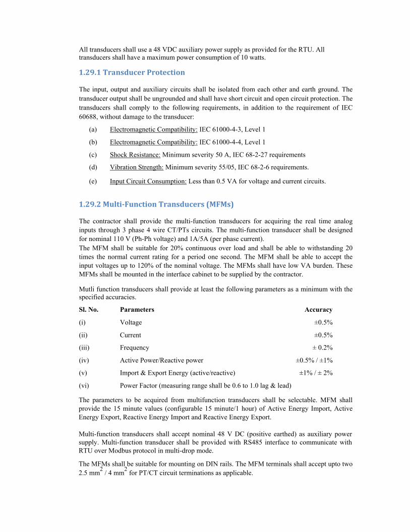
All transducers shall use a 48 VDC auxiliary power supply as provided for the RTU. All transducers shall have a maximum power consumption of 10 watts.
1.29.1 Transducer Protection The input, output and auxiliary circuits shall be isolated from each other and earth ground. The transducer output shall be ungrounded and shall have short circuit and open circuit protection. The transducers shall comply to the following requirements, in addition to the requirement of IEC 60688, without damage to the transducer:
(a) Electromagnetic Compatibility: IEC 61000-4-3, Level 1
(b) Electromagnetic Compatibility: IEC 61000-4-4, Level 1
(c) Shock Resistance: Minimum severity 50 A, IEC 68-2-27 requirements
(d) Vibration Strength: Minimum severity 55/05, IEC 68-2-6 requirements.
(e) Input Circuit Consumption: Less than 0.5 VA for voltage and current circuits.
1.29.2 Multi-Function Transducers (MFMs) The contractor shall provide the multi-function transducers for acquiring the real time analog inputs through 3 phase 4 wire CT/PTs circuits. The multi-function transducer shall be designed for nominal 110 V (Ph-Ph voltage) and 1A/5A (per phase current). The MFM shall be suitable for 20% continuous over load and shall be able to withstanding 20 times the normal current rating for a period one second. The MFM shall be able to accept the input voltages up to 120% of the nominal voltage. The MFMs shall have low VA burden. These MFMs shall be mounted in the interface cabinet to be supplied by the contractor. Mutli function transducers shall provide at least the following parameters as a minimum with the specified accuracies. Sl. No. Parameters Accuracy
(i) Voltage ±0.5%
(ii) Current ±0.5%
(iii) Frequency ± 0.2%
(iv) Active Power/Reactive power ±0.5% / ±1%
(v) Import & Export Energy (active/reactive) ±1% / ± 2% (vi) Power Factor (measuring range shall be 0.6 to 1.0 lag & lead) The parameters to be acquired from multifunction transducers shall be selectable. MFM shall provide the 15 minute values (configurable 15 minute/1 hour) of Active Energy Import, Active Energy Export, Reactive Energy Import and Reactive Energy Export. Multi-function transducers shall accept nominal 48 V DC (positive earthed) as auxiliary power supply. Multi-function transducer shall be provided with RS485 interface to communicate with RTU over Modbus protocol in multi-drop mode. The MFMs shall be suitable for mounting on DIN rails. The MFM terminals shall accept upto two 2.5 mm
2 / 4 mm
2 for PT/CT circuit terminations as applicable.
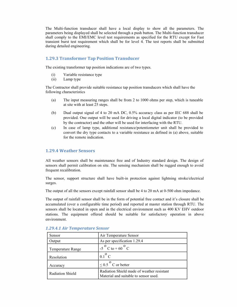
The Multi-function transducer shall have a local display to show all the parameters. The parameters being displayed shall be selected through a push button. The Multi-function transducer shall comply to the EMI/EMC level test requirements as specified for the RTU except for Fast transient burst test requirement which shall be for level 4. The test reports shall be submitted during detailed engineering.
1.29.3 Transformer Tap Position Transducer The existing transformer tap position indications are of two types.
(i) Variable resistance type (ii) Lamp type
The Contractor shall provide suitable resistance tap position transducers which shall have the following characteristics
(a) The input measuring ranges shall be from 2 to 1000 ohms per step, which is tuneable at site with at least 25 steps.
(b) Dual output signal of 4 to 20 mA DC, 0.5% accuracy class as per IEC 688 shall be
provided. One output will be used for driving a local digital indicator (to be provided by the contractor) and the other will be used for interfacing with the RTU.
(c) In case of lamp type, additional resistance/potentiometer unit shall be provided to convert the dry type contacts to a variable resistance as defined in (a) above, suitable for the remote indication.
1.29.4 Weather Sensors All weather sensors shall be maintenance free and of Industry standard design. The design of sensors shall permit calibration on site. The sensing mechanism shall be rugged enough to avoid frequent recalibration. The sensor, support structure shall have built-in protection against lightning stroke/electrical surges. The output of all the sensors except rainfall sensor shall be 4 to 20 mA at 0-500 ohm impedance. The output of rainfall sensor shall be in the form of potential free contact and it’s closure shall be accumulated (over a configurable time period) and reported at master station through RTU. The sensors shall be located in open and in the electrical environment such as 400 KV EHV outdoor stations. The equipment offered should be suitable for satisfactory operation in above environment.
1.29.4.1 Air Temperature Sensor
Sensor Air Temperature Sensor
Output As per specification 1.29.4
Temperature Range -5 o
C to + 60 o
C
Resolution 0.1o
C
Accuracy < 0.5 o
C or better
Radiation Shield Radiation Shield made of weather resistant Material and suitable to sensor used.
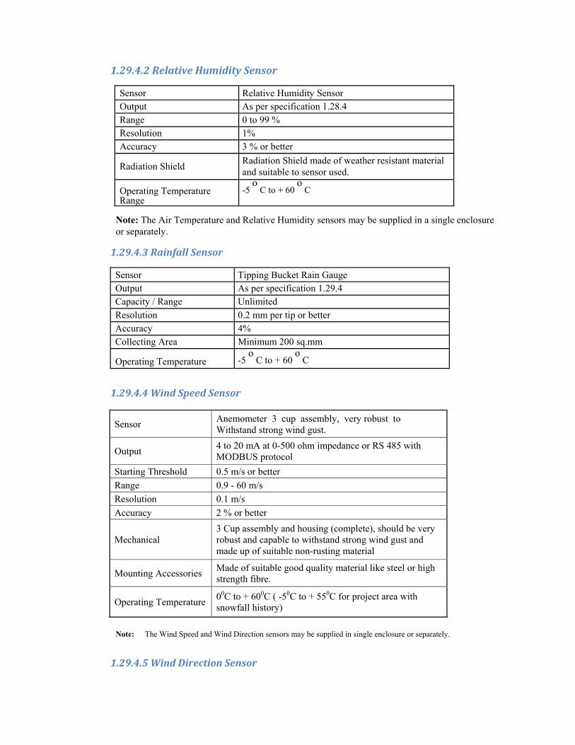
1.29.4.2 Relative Humidity Sensor
Sensor Relative Humidity Sensor
Output As per specification 1.28.4
Range 0 to 99 %
Resolution 1%
Accuracy 3 % or better
Radiation Shield Radiation Shield made of weather resistant material and suitable to sensor used.
Operating Temperature -5 o
C to + 60 o
C Range
Note: The Air Temperature and Relative Humidity sensors may be supplied in a single enclosure or separately.
1.29.4.3 Rainfall Sensor
Sensor Tipping Bucket Rain Gauge
Output As per specification 1.29.4
Capacity / Range Unlimited
Resolution 0.2 mm per tip or better
Accuracy 4%
Collecting Area Minimum 200 sq.mm
Operating Temperature -5 o
C to + 60 o
C
1.29.4.4 Wind Speed Sensor
Sensor Anemometer 3 cup assembly, very robust to Withstand strong wind gust.
Output 4 to 20 mA at 0-500 ohm impedance or RS 485 with MODBUS protocol
Starting Threshold 0.5 m/s or better
Range 0.9 - 60 m/s
Resolution 0.1 m/s
Accuracy 2 % or better
Mechanical 3 Cup assembly and housing (complete), should be very robust and capable to withstand strong wind gust and made up of suitable non-rusting material
Mounting Accessories Made of suitable good quality material like steel or high strength fibre.
Operating Temperature 00C to + 600C ( -50C to + 550C for project area with snowfall history)
Note: The Wind Speed and Wind Direction sensors may be supplied in single enclosure or separately.
1.29.4.5 Wind Direction Sensor

Sensor Wind Direction sensorOutput 4 to 20 mA at 0-500 ohm impedance or RS 485 with
MODBUS protocolStarting Threshold 0.5 m/s or betterRange 0 – 360o (Degrees) Resolution 1o (Degree) Accuracy 3o (Degrees) or betterConstruction of Housing (complete) should be very robust and Housing and vane capable to withstand strong wind gust and made up of
suitable-non-rusting material having high mechanical strength. Wind vane and control head may be of Aluminum or other light UV resistant material
Operating Temperature 0oC to + 60oC (-5oC to + 55oC for project area with snowfall history)
1.29.4.6 Air Temperature Sensor Sensor Air Temperature Sensor
Output 4 to 20 mA at 0-500 ohm impedance or RS 485 with MODBUS protocol
Temperature Range 00C to + 600C ( -50C to + 550C for project area with snowfall history)
Resolution 0.10C Accuracy < 0.5⁰C or better
Radiation Shield Radiation Shield made of weather resistant material and suitable to sensor used.
1.29.4.7 Weather Sensor Installation Requirement
The weather sensor shall be supplied along with necessary accessories (e.g. tripod, stand, clamps etc.) for installation/ fixing of sensors, signal/power cables etc. as part of weather sensors station. All the accessories shall be made of stainless steel or other suitable material having sufficient mechanical strength and corrosion resistance to withstand atmospheric temperature, pressure, wind speed and relative humidity up to the working range(Minimum to Maximum) of sensors for these parameters as defined.
The Employer will prefer to install the sensors on roof top of control centre/substation or other building. The mounting arrangement for all the sensors shall be designed suitably for installation on the roof top.
1.30 Portable Configuration and Maintenance Terminal (PCMT) Contractor shall supply a Portable Configuration and maintenance Terminal (Laptop PC) which shall provide followings capabilities:
(a) RTU Data base configuration & Maintenance
(b) Local Operator Interface & RTU Diagnostics
(c) Master Station and RTU simulator cum protocol analyzer

a) RTU Data base configuration The RTU database Configuration software being supplied with the PCMT shall have the following features
i) Full graphics windows User Interface
ii) Standard editing capabilities e.g. cut, paste, copy, sorting etc.
iii) Capable of controlling revisions of various RTU database files and storing multiple versions of databases for all the RTUs.
iv) Capable of uploading database from the RTU and compare that with another
version of database stored in the PCMT.
v) Provide standard template for database modeling required for I/O modules, MFMs & IEDs, communication setting.
vi) Provide mapping of the individual data points acquired from one
Protocol to another protocol for transmission. The database configuration software shall use the same terminology for configuration of the various protocol parameters as specified in the communication protocol standard i.e. it shall be possible to define these parameters by the user discreetly. Also it shall be possible to select an ASDU type to be used for transmission of a measurand e.g. measured value to be transmitted as ASDU 9 or ASDU 11.
b) Local Operator interface and RTU diagnostics The Local Operator interface software shall support operator inquiries to demand current status and data values of various RTU points, or an overall substation snap-shot, or of the status change buffer. The local operator interface software shall provide the following reports:
i) Status Reports: Display of all substation status indications, of all tele-metered values, and the RTU's status.
ii) Event Report: Display all the stored events in the event buffer of the RTU.
iii) Print Request: Provide user interface for requesting print out of the Reports on the
Logger iv) Maintenance activities: User interface for interacting with the RTU for maintenance
activities like diagnostics, database online requests. The RTU shall have inbuilt features for monitoring the healthiness of the RTU modules and detecting the type of error. The diagnostics software shall have diagnostics for the RTU's processor(s), memory, I/O ports, and any other functional areas of the RTU. It shall list the errors recorded by the RTU and provide troubleshooting tools for the RTU.
c) Master station-cum-RTU simulator & protocol analyzer software tool The Master station and RTU simulator cum Protocol Analyser software shall be used to monitor and test the RTU's operation using the master station communication protocol. It shall have the following features

i) capable of emulating both the master station and the RTU messages in the
communication protocols (IEC 60870-5-101, 104 & MODBUS/103). When the Master station and RTU simulator cum Protocol Analyser software has received or transmitted a message, it shall be possible to immediately "turn around" and transmit or receive a response message.
ii) capability of interfacing to digital side of the RTU for the above purpose.
iii) capable of receiving single and repeated messages using the supplied RTU
communication protocol. Each received message shall be checked for validity, including the checksum code. The messages shall be displayed in HEX format or in the ‘interpreted form’ as desired by the user . It shall maintain and display error counters so that the number of errors during a period of unattended testing can be accurately determined.
iv) capable of formatting and transmitting, both as one-time and periodic transmissions,
any master station-to-RTU command.
v) capable of preparing illegal messages, such as messages having invalid check codes, for transmission.
The Master station and RTU simulator cum Protocol Analyser software shall also be capable of passively monitoring all communication traffic on a channel without inter-fering with channel operation. Channel traffic captured in the active or passive modes of operation shall be displayed. All fields of a message shall be displayed. A pass/fail indication for the security check code shall be included with each code displayed.
1.31 Training, Documentations and TESTING
1.31.1 TRAINING The contractor shall provide training to the Employer’s personnel. The training program shall be comprehensive and provide for interdisciplinary training on hardware and software. The training program shall be conducted in English. RTU/FRTU training course shall cover the following: a) RTU/FRTU operation including data flow. b) Troubleshooting, identification and replacement of faulty Modules. c) Preventive maintenance of the RTU/FRTU d) Use of RTU/FRTU configuration and Maintenance tool e) All functional and Diagnostic testing of RTU/FRTU f) Database modification and configuration of RTU/FRTU
1.31.2 DOCUMENTATION The Contractor shall submit 3 sets of all the standard and customized RTU documents for review and approval which includes the following: a) RTU Function design document b) RTU Hardware description document & all the documents referred therein to meet all the
clauses of the specification. c) RTU Test equipment user documents d) RTU user guide
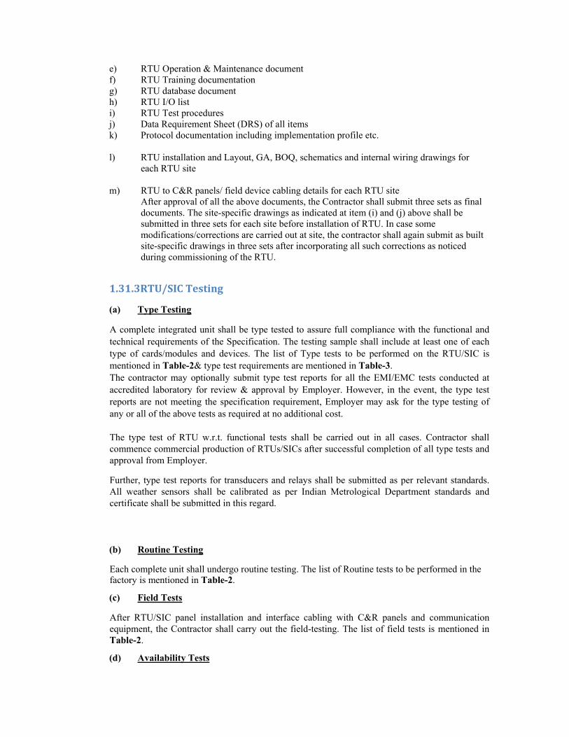
e) RTU Operation & Maintenance document f) RTU Training documentation g) RTU database document h) RTU I/O list i) RTU Test procedures j) Data Requirement Sheet (DRS) of all items k) Protocol documentation including implementation profile etc. l) RTU installation and Layout, GA, BOQ, schematics and internal wiring drawings for
each RTU site m) RTU to C&R panels/ field device cabling details for each RTU site
After approval of all the above documents, the Contractor shall submit three sets as final documents. The site-specific drawings as indicated at item (i) and (j) above shall be submitted in three sets for each site before installation of RTU. In case some modifications/corrections are carried out at site, the contractor shall again submit as built site-specific drawings in three sets after incorporating all such corrections as noticed during commissioning of the RTU.
1.31.3RTU/SIC Testing (a) Type Testing A complete integrated unit shall be type tested to assure full compliance with the functional and technical requirements of the Specification. The testing sample shall include at least one of each type of cards/modules and devices. The list of Type tests to be performed on the RTU/SIC is mentioned in Table-2& type test requirements are mentioned in Table-3. The contractor may optionally submit type test reports for all the EMI/EMC tests conducted at accredited laboratory for review & approval by Employer. However, in the event, the type test reports are not meeting the specification requirement, Employer may ask for the type testing of any or all of the above tests as required at no additional cost. The type test of RTU w.r.t. functional tests shall be carried out in all cases. Contractor shall commence commercial production of RTUs/SICs after successful completion of all type tests and approval from Employer. Further, type test reports for transducers and relays shall be submitted as per relevant standards. All weather sensors shall be calibrated as per Indian Metrological Department standards and certificate shall be submitted in this regard. (b) Routine Testing Each complete unit shall undergo routine testing. The list of Routine tests to be performed in the factory is mentioned in Table-2. (c) Field Tests After RTU/SIC panel installation and interface cabling with C&R panels and communication equipment, the Contractor shall carry out the field-testing. The list of field tests is mentioned in Table-2. (d) Availability Tests
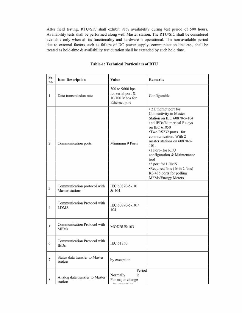
After field testing, RTU/SIC shall exhibit 98% availability during test period of 500 hours. Availability tests shall be performed along with Master station. The RTU/SIC shall be considered available only when all its functionality and hardware is operational. The non-available period due to external factors such as failure of DC power supply, communication link etc., shall be treated as hold-time & availability test duration shall be extended by such hold time.
Table-1: Technical Particulars of RTU
Sr. Item Description Value
Remarks
no.
300 to 9600 bps
1 Data transmission rate for serial port &
Configurable 10/100 Mbps for
Ethernet port
• 2 Ethernet port for Connectivity to Master Station on IEC 60870-5-104 and IEDs/Numerical Relays on IEC 61850 •Two RS232 ports –for communication. With 2
2 Communication ports Minimum 9 Ports master stations on 60870-5- 101.
•1 Port– for RTU configuration & Maintenance tool •2 port for LDMS •Required Nos ( Min 2 Nos) RS 485 ports for polling MFMs/Energy Meters
3 Communication protocol with IEC 60870-5-101 Master stations & 104
Communication Protocol with IEC 60870-5-101/
4 LDMS
104
5 Communication Protocol with
MODBUS/103
MFMs
6 Communication Protocol with
IEC 61850
IEDs
7 Status data transfer to Master
by exception
station
Analog data transfer to Master
Normally Periodic
8 For major change
station by exception

9 No. of Scan Groups supported 16
10 Separate Logical Database for each Master Station
11 RTU shall be able to capture of 20 ms or more contact operations duration.
12 SOE buffer size atleast 1024 events
13 Time stamping accuracy for
1 ms
SOE
14 Supporting Control of Devices Two state & OLTC capacitors
15 Down loading of RTU
Supported
database from master station
16 RTU internal clock stability Atleast 1 ppm
17 Nominal Power supply voltage 48V DC
18 Compliance to cl. 1.29.1 – Transducer Protection

Table-2: List of Tests on RTU/SIC
Test DESCRIPTION OF THE TEST Type test Routine FieldNos test test
. FUNCTIONAL TESTS FOR RTU/SIC
1. Check for BOQ, Technical details, Construction & Wiring as √ √ √per RTU/FRTU/SIC drawings
2. Check for RTU database & configuration settings √ √ √
3. Check the operation of all Analog inputs, Status input & √ √ √Control output points of RTU/SIC
4. Check operation of all communication ports of RTU/FRTU √ √ √
5. Check for communication with master stations or master √ √ √station simulator for RTU/ FRTU
6. Test for downloading of RTU database from Master station √ 7. Test for RTU time synchronization from Master √ √
8. Test Power Supply Voltage Margin, Ripple Levels and Short √ Circuit Protection
9. Test for RTU operation with DC power supply voltage variation √
10. Check for auto restoration of RTU on DC power recovery after √ √ √its failure
11. Test for RTU/ FRTU diagnostic feature √ 12. Test for RTU SOE feature √ 13. RTU Analog accuracy test for analog input √ 14. Transducer accuracy test √ √
15. Test for IEC 60870-5 -104, 61850 & Modbus protocol √ implemented
16. Test for RTU internal Clock stability √ 17. Test for RTU Noise level measurement √ 18. Test for Control Security and Safety for Control outputs √
19. Other functional tests as per technical specification √ requirements
20. End to end test (between RTU/ FRTU & Master station) for all √I/O points
EMI/EMC IMMUNITY TESTS FOR RTU/ FRTU 21. Surge Immunity Test as per IEC 60870-2-1 √ 22. Electrical Fast Transient Burst Test as per IEC-60870-2-1 √ 23. Damped Oscillatory Wave Test as per IEC 60870-2-1 √ 24. Electrostatic Discharge test as per √ 25. Radiated Electromagnetic Field Test as per IEC 60870-2-1 √ 26. Damped Oscillatory magnetic Field Test as per IEC-60870-2-1 √ 27. Power Frequency magnetic Field Test as per IEC-60870-2-1 √
INSULATION TEST FOR RTU/ FRTU 28. Power frequency voltage withstand Test as per IEC 60870-2-1 √
29. 1.2/50 µs Impulse voltage withstand Test as per IEC 60870-2-1 √
30. Insulation resistance test √ ENVIRONMENTAL TEST FOR RTU/ FRTU
31. Dry heat test as per IEC60068-2-2 / 2-3 √ 32. Damp heat test as per IEC60068-2-78 √ 33. Cold Test as per IEC60068-2-1 √
Note: Test levels for above type tests are elaborated in Table 3

Table-3: RTU Type Test Requirements
Test Test Name EUT Test Power Supply I/O PassingNos Status Level Points Points Criteria. CM DM CM 1 Surge Immunity Test ON Level 2 kV 1 kV 2 kV A
3 2 Electrical Fast ON Level 2 KV - 1 kV A
Transient Burst Test 3 3 Damped Oscillatory ON Level 2.5 kV 1 kV 2.5 kV A
Wave Test 3 4 Electrostatic ON Level +/- 6 kV in Contact discharge A
Discharge Test 3 mode or +/- 8 kV in Air discharge mode
5 Radiated ON Level 10 V/m electric field strength A Electromagnetic Field 3 Test
6 Damped Oscillatory ON Level 30 A/m at 1MHz of magnetic A Magnetic Field Test 3 field strength
7 Power frequency ON Level 30 A/m of magnetic field strength A magnetic field 3 (Continuous duration sine wave)
8 Power frequency OFF - 1 KVrms for 1 minute No break voltage withstand down or flashover shall occur
9 1.2/50µs impulse OFF - No break voltage withstand down or 2 kVp flashover shall occur
11 Insulation Resistance OFF - Measure Insulation resistance As per Test using 500 V DC Megger before manufact & after Power Freq& Impulse urer voltage withstand tests standard
12 Dry heat test ON - Continuous operation at 550
C 0 for 16 hrs
13 Damp heat test ON - at 95% RH and 400
C for 16 hrs 014 Cold test ON - Continuous operation at 0
0 C for 0
96 hrs
Note:- 1. EUT - Equipment Under Test 2. CM - Common Mode; DM - Differential mode 3. I/O pints do not include Communication ports 4. Passing Criteria
0 - no failure: normal performance within the specified limits A : minor failure : temporary degradation or loss of function or performance which is self-recoverable
5. Functional test as per the sl. nos. 1-18 of Table-2 shall also be done during type testing.

Appendix A: I/o Count New RTUs
Total Double Status Points
Single Status Points
Single Status Points
Total
Total No. of Bays
Total No. of MFM/
MFT
CB(NO &
NC)
Protection/Alarms
Isolators
DO
DI (Digital Status input)
MFT/MFM(MODBUS/IEC
60870-5-103)S.No.
Name of the Sub-station
Wea
ther
Sen
sor
OL
TC
Tra
nsd
uce
rs(4
-20
mA
)
AI & Transducers
DC
Cap
abili
ty
LD
MS
Sys
tem
Nos
GP
S S
yste
m &
In
terf
ace