Embed Size (px)
Citation preview

A Project on Construction of Pile Foundation
Under MACKINTOSH
BURN LIMITED
Bored Cast-in-situ Piles as Adopted in English Medium High Madrasha Job Site, Malda

Content Sl. No. Subject Page No.
1. CONTRIBUTED BY 1
2. INTRODUCTION 2
3. TERMINOLOGY 3-4
4. PILE CLASSIFICATION 5
5. ABOUT THE PROJECT 6-7
6. REPORT ON CONCRETE MIX DESIGN (M25) 8-11
7. REPORT ON PILE LOAD TESTING 12-15
8. PILE COMPRESSION LOAD TEST BY KENTLEDGE SYSTEM 16-18
9. (COMPRESSION TEST OF CONCRETE) CUBE TEST 19-20
10. THE SLUMP TEST OF CONCRETE 21-22
11. AGGREGATES (FINENESS MODULUS TEST FOR COARSE AGGREGATE)
23-24
12. GENERAL DESCRIPTION OF WORK 25
13. EXECUTION OF CONSTRUCTION WORKS AT SITE 26-27
14. WORKMANSHIP 28-30
15. PILE CUT OFF, EXCAVATION AND CLEAN-UP 31
16. REQUIREMENTS OF DRILLING MUD (BENTONITE) 32
17. PICTURES 33-35
18. CONCLUTION 36

2 | P a g e
INTRODUCTION:
The use of Piles as a foundation can be traced since olden times. The art of driving piles was well- established in Roman times and the details of such foundations were recorded by Vitruvius in 59 A.D. Today, pile foundation is much more common than any other types of deep foundation. Modern pile driving started with the first steam pile drivers, invented by Nasmyth in 1845. Piles may be classified as follows –
A> Classification based on the function:
Based on the function or the use, piles may be classified as:-
1. End Bearing Pile.
2. Friction Pile.
3. Compaction Pile.
4. Tension Pile or Uplift Pile.
5. Anchor Pile.
6. Fender Pile and Dolphins.
7. Batter Pile.
8. Sheet Pile.
B> Classification based on material and composition:
1. Concrete Piles : A. Precast B. Cast-in-situ.
I. Driven Piles: Cased or Uncased. II. Bored Piles: Pressure Piles and under-reamed pipes.
2. Timber Piles :
3. Steel Piles :
A. H-piles.
B. Pipe pile.
C. Sheet Pile.
4. Composite Pile :
A. Concrete and timber.
B. Concrete and steel.
Here, we will discuss about Bored cast-in-situ piles. In this method, Boring is done either by auguring or by
percussion drilling. The bottom of the bore may be under-reamed according to requirements. After boring
is concreted with or without reinforcement.
A pile is driven by a pile driving rig which consists of a frame, a winch and impact hammers. The hammers
may be the drop type, single acting or double-acting steam hammers or the vibrating type. The weights of
hammers depend upon the type of length of piles. For a single-acting hammer, weight vary from 1500 to
10,000 kg and for double acting from 350 kg to 2500 kg.
Sometimes, water jetting is used for driving piles in firm to stiff clays or soils mixed with cobbles or
boulders. Percussion drilling is some time times adopted in soils mixed with gravels and boulders.

3 | P a g e
TERMINOLOGY:
For the purpose of this project, the following definitions will be needed.
Allowable Load: —
The load which may be applied to a pile after taking into account its ultimate load capacity, group effect,
the allowable settlement, negative skin friction and other relevant loading conditions.
Anchor Pile —
An anchor pile means a pile meant for resisting pull or uplift forces.
Bored Cast In-situ Pile —
A pile formed by boring a hole in the ground by percussive or rotary method with the use of
temporary/permanent casing or drilling mud and subsequently filling the hole with reinforced concrete.
Cut-off Level —
It is the level where a pile is cut-off to support the pile caps or beams or any other structural components
at that level.
Diameter of Piles —
Piles of 600 mm or less in diameter are commonly known as small diameter piles while piles greater than
600 m diameter are called large diameter piles. Minimum pile diameter shall be 450 mm.
Elastic Displacement —
This is the magnitude of displacement of the pile head during rebound on removal of a given test load.
This comprises two components:
A. Elastic displacement of the soil participating in the load transfer, and
B. Elastic displacement of the pile shaft.
Factor of Safety —
It is the ratio of the ultimate load capacity of a pile to the safe load on the pile.
Gross Displacement —
The total movement of the pile top under a given load.
Initial Load Test —
A test pile is tested to determine the load-carrying capacity of the pile by loading either to its ultimate
load or to twice the estimated safe load.
Initial Test Pile —
One or more piles, which are not working piles, may be installed if required to assess the load-carrying
capacity of a pile. These piles are tested either to their ultimate load capacity or to twice the estimated
safe load.
Load Bearing Pile —
A pile formed in the ground for transmitting the load of a structure to the soil by the resistance developed
at its tip and/or along its surface. It may be formed either vertically or at an inclination (batter pile) and
may be required to resist uplift forces.
If the pile supports the load primarily by resistance developed at the pile tip or base it is called ‘End
bearing pile’ and, if primarily by friction along its surface, then ‘Friction pile’.
4 | P a g e
Net Displacement —
The net vertical movement of the pile top after the pile has been subjected to a test load and subsequently
released.
Pile Spacing —
The spacing of the piles means the centre-to-centre distance between adjacent piles.
Routine Test Pile —
A pile which is selected for load testing may form a working pile itself, if subjected to routine load test up
to one and 1.5 times the safe load.
Safe Load —
It is the load derived by applying a factor of safety on the ultimate load capacity of the pile or as
determined from load test.
Ultimate Load Capacity — The maximum load which a pile can carry before failure, that is, when the founding strata fails by shear
as evidenced from the load settlement curve or the pile fails as a structural member.
Working Load —
The load assigned to a pile as per design.
Working Pile —
A pile forming part of the foundation system of a given structure.
Negative Skin Friction or Dragdown Force — When a soil stratum, through which a pile shaft has penetrated into an underlying hard stratum,
compresses as a result of either it being unconsolidated or it being under a newly placed fill or as a result
of remoulding during installation of the pile, a dragdown force is generated along the pile shaft up to a
point in depth where the surrounding soil does not move downward relative to the pile shaft. Existence of
such a phenomenon shall be assessed and suitable correction shall be made to the allowable load where
appropriate.

5 | P a g e
PILE CLASSIFICATION:
The word ‘pile’ is used to describe columns, usually of reinforced concrete, driven into or cast in the ground in order to carry foundation loads to some deep underlying firm stratum or to transmit loads to the subsoil by the friction of their surfaces in contact with the subsoil. The main function of a pile is to transmit loads to lower levels of ground by a combination of friction along their sides and end bearing at the pile point or base .Piles that transfer loads mainly by friction to clays and silts are termed friction piles and those that mainly transfer loads by end bearing to compact gravel, hard clay or rock are termed end -bearing piles. Four or more piles may be used to support columns of framed structures. The columns are connected to a reinforced concrete pile cap connected to the pile. Piles may be classified by their effect on the subsoil as displacement piles or non-displacement piles. Displacement piles are driven, forced or cut (by an auger) into the ground to displace subsoil. The strata are penetrated.
Fig :- Main Functions of Piles – End Bearing (left) and Friction (right)
No soil is removed during the operation. Solid concrete or steel piles and piles formed inside tubes which
are driven into the ground and which are closed at their lower end by a shoe or plug, which may either be
left in place or extruded to form an enlarged toe, are all forms of displacement pile. Non-displacement piles
are formed by boring or other methods of excavation that do not substantially displace subsoil. Sometimes
the borehole is lined with a casing or tube that is either left in place of extracted as the hole is filled. Driven
piles are those formed by driving a precast pile and those made by casting concrete in a hole formed by
driving. Bored piles are those formed by casting concrete in a hole previously bored or drilled in the subsoil.

6 | P a g e
ABOUT THE PROJECT :
Total Estimated Cost Put To Tender:- 9 Crore 94 Lakh.
Tender Amount (5.18% Less From Estimated Cost):- 9.42 cr. (942.86 Lakh).
Concrete Used:- M25
Number of Piles:- 251
Number of Piles Daily Completed:- 6
Diameter of Pile:- 0.45 M
Length of Pile Along With 1.6 M Cut Off:- 20.6 M
Area of Pile:- 3.18 Cubic M
Cement Used in Each Pile:- 26 Bags
Design Load on Each Pile:- 45 Tons
Cut Off Length of Pile:- 1.6 M
About the equipments of piling :-
Reinforcements
Full Length Rods Used in 1st Reinforcement:- 4 ( 12 M Each )
Half Length Rods Used in 1st Reinforcement:- 3 (11.4 M Each )
Stirrups Used in 1st Reinforcement:- 72 Pieces
Stiffeners Used in 1st Reinforcement:- 8 Pieces
Covered Blocks Used in 1st Reinforcement:- 12 ( In 3 by 3 Seq. )
Full Length Rods Used in 2nd Reinforcement:- 3 (9.1 M Each )
Half Length Rods Used in 2nd Reinforcement:- 4 (8.4 M Each )
Stirrups Used in 2nd Reinforcement:- 48 Pieces
Stiffeners Used in 2nd Reinforcement:- 5 Pieces
Covered Blocks Used in 2nd Reinforcement:- 9 (In 3 by 3 Seq. )
DMC PIPES
Length of 1st DMC Pipe:- 3.41 M
Length of 2nd DMC Pipe:- 3.47 M
Length of 3rd DMC Pipe:- 3.05 M
Length of 4th DMC Pipe:- 3.409 M
Length of 5th DMC Pipe:- 2.707 M
Length of 6th DMC Pipe:- 2.106 M
Diameter of DMC Pipes:- 0.165 M
TREMIE PIPES
Length of Tremie Pipes:- 2.65 M
Diameter of Tremie Pipes:- 0.213 M

7 | P a g e
CHISEL
Length of Chisel:- 2.71 M
Diameter of Chisel:- 0.39 M
BAILER
Length of Bailer:- 3 M
Diameter of Bailer:- 0.39 M
CASING
Length of Casing:- 2.2 M
Diameter of Casing:- 0.45 M
HOPPER
Height of Hopper:- 0.915 M
Diameter of Hopper Mouth:- 1.25 M
Diameter of Hopper Link:- 0.205 M
STIRRUPS & STIFFENERS
Distance between Two Stirrups:- 0.15 M
Distance between Two Stiffeners:- 1.4 M
DEVELOPMENT LENGTH & LAP LENGTH
Development Length of Reinforcement:- 0.15 M
Lap Length in Reinforcement:- 0.8 M
DIAMETER OF BARS
Diameter of Main Bars:- 12 MM
Diameter of Stirrup Bars:- 8 MM
Diameter of Stiffener Bars:- 12 MM
CEMENT & ADMIXTURE
Type of Cement Used:- Portland Pozzolana Cement ( PPC )
Type of Admixture Used:- Bentonite Powder

8 | P a g e
REPORT ON CONCRETE MIX DESIGN (M-25):
SAMPLE SUPPLIED BY :- Project In Charge, Malda Medical College Project REF. NO :- PLL/Lab/04/2011 DATE : 15-07-2011
DESIGN CRITERIA :-
1) Characteristic Compressive Strength :- 25 MPa. 2) Maximum Size of the Aggregate :- 20 mm. 3) Degree of Workability :- Medium ( Slump 100 mm ) 4) Compacting Factor :- 0.90 5) Degree of Quality Control :- Good. 6) Type of Exposure :- Mild.
TEST DATA OF THE SUPPLIED MATERIALS :-
1) Cement Used :- Portland Pozzolana Cement. Conforming I.S-1489
2) Specific Gravity of the Cement :- 3.00 3) Specific Gravity of the Fine Aggregate :- 2.65 4) Specific Gravity of the Coarse Aggregate :- 2.85 5) Initial Setting Time of Cement :- 135 min. 6) Final setting Time of Cement :- 200 min. 7) Compressive Strength of Cement at 3 days :- 25 MPa. 8) Compressive Strength of Cement at 7 days :- 35 MPa.
GRADING OF AGGREGATES :-
A. FINE AGGREGATE :-
SIEVE SIZES ( MM ) WT. RETAINED ( Gm ) CUMULATIVE WT. RETAINED ( GM )
% AGE CUMULATIVE WT. RETAINED
( GM )
10 0 0 0
4.75 4.00 4.00 0.40
2.36 13.50 17.50 1.75
1.18 219.00 236.50 23.65
0.600 361.50 598.00 59.80
0.300 271.50 869.50 86.95
0.15 38.50 908.00 90.00
RESIDUE 92.00 10000.00 100.00
REMARK :- Conforming to Grading Zone II ( F.M.-2.62 ) as per I.S :- 383-1970
9 | P a g e
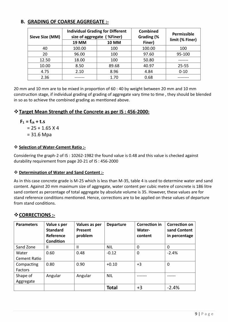
B. GRADING OF COARSE AGGREGATE :-
Sieve Size (MM) Individual Grading for Different
size of aggregate ( %Finer) Combined Grading (%
Finer)
Permissible limit (% Finer)
19 MM 10 MM
40 100.00 100 100.00 100
20 96.00 100 97.60 95-100
12.50 18.00 100 50.80 -------
10.00 8.50 89.68 40.97 25-55
4.75 2.10 8.96 4.84 0-10
2.36 ------- 1.70 0.68 --------
20 mm and 10 mm are to be mixed in proportion of 60 : 40 by weight between 20 mm and 10 mm construction stage, if individual grading of grading of aggregate vary time to time , they should be blended in so as to achieve the combined grading as mentioned above.
Target Mean Strength of the Concrete as per IS : 456-2000:
F1 = fck + t.s = 25 + 1.65 X 4 = 31.6 Mpa
Selection of Water-Cement Ratio :-
Considering the graph-2 of IS : 10262-1982 the found value is 0.48 and this value is checked against durability requirement from page 20-21 of IS : 456-2000
Determination of Water and Sand Content :-
As in this case concrete grade is M-25 which is less than M-35, table 4 is used to determine water and sand content. Against 20 mm maximum size of aggregate, water content per cubic metre of concrete is 186 litre sand content as percentage of total aggregate by absolute volume is 35. However, these values are for stand reference conditions mentioned. Hence, corrections are to be applied on these values of departure from stand conditions.
CORRECTIONS :-
Parameters Value s per Standard Reference Condition
Values as per Present problem
Departure Correction in Water-content
Correction on sand Content in percentage
Sand Zone II II NIL 0 0
Water Cement Ratio
0.60 0.48 -0.12 0 -2.4%
Compacting Factors
0.80 0.90 +0.10 +3 0
Shape of Aggregate
Angular Angular NIL ------- ------
Total +3 -2.4%

10 | P a g e
Corrected Water Content :-
186.00 Kg/m³ X 1.03 = 191.6 lit/m³ Corrected sand content as percentage of total Aggregate by absolute volume = (35.00 – 2.40) = 32.60 In Fraction i.e. P = 32.6/100 = 0.326
Calculation of Cement Content:-
Water Cement Ratio -> 0.48 Water Content -> 1910.6 Therefore, Cement Content = 191.6/0.48 = 399.16 Kg/m³ say 400 kg/cum. This value is to be checked calculated for durability requirement from IS: 456. Here, against the mild exposure and for the case of Reinforced concrete minimum cement content is 300 kg/cum, which is less than 450 kg/cum. Hence, Cement content adopted = 400 kg/cum.
Determination of F.A and C.A Content :-
1-0.02 = [191.6+399.00/3.00 + 1/0.326 X Wf /2.65] X 1/1000 Which leads to Wf = 562.73 kg/cum
1-0.02 = [191.60 + 399.00 / 3.00 + 1 / (1-0.326) X Wc /2.85] X 1/1000 Therefore, the Wc = 1258.95 kg/cum
As CA I and CA II are in proportion of 60 : 40, The weight of CA I and CA II per cum of concrete are 755.37 kg and 503.58 kg.
The required proportion is:-
Water 191.60 0.48
Cement 399.00 1
FA 562.73 1.41
CA I 755.37 1.89
CA II 503.58 1.26
Correction due to absorbing/ moist aggregate :-
If Fine Aggregate has any amount of surface moisture, which it will contribute towards mixing water. Hence, so much water has to be deduced from mixing water. After contributing the surface moisture (i.e. after it attains SSD condition) It’s weight decreases hence so much water is to be added with the weight of F.A. Generally, the coarse aggregate at sight is absorbing type and it’s water absorption is to be founded out. The calculated absorbed amount of water is to be added to the mixing water and consequently that amount is to deduced from the weight of C.A.

11 | P a g e
RESULTS OF TRIAL MIXES :-
Trial Mix no.
Quantity of Material per Cubic Metre of Concrete (Kg)
Concrete Characteristics
Remarks Cement & W/C Ratio
Water Content
Sand CA I CA II Workability
(CF) Visual
Observation
28 Days Compressive
Strength(MPa)
1 399.00
W/C=0.48 191.60 562.73 755.37 503.58 0.86
Cohesive Slump-75MM
30.44 For all cases
Correction has to be applied
2 400.00
W/C=0.48 192.00 565.57 754.53 503.02 0.90
Cohesive Slump-100MM
32.44
3 446.51
W/C=0.43 192.00 552.17 736.66 491.10 0.78
Non Cohesive
34.66
4 362.26
W/C=0.53 192.00 57 769.03 512.69 0.95
Cohesive but Slump
More than !00
MM
28.67 Non
Required
SO THE FINAL PROPORTION OF THE MIX DESING M-25 IS AS FOLLOWS:-
Water CEMENT FA CA I CA II 192.00 400.00 565.57 754.53 503.02
0.48 1 1.414 1.89 1.26
To obtain 150-180 MM slump add SUPERPLASTISIZER @ 2% by weight of cementitious material.

12 | P a g e
TITLE:- VERTICAL LOAD TEST (ROUTINE)
PILE NO:- P92
DATE OF TESTING:- 21.12.2015 & 22.12.2015
CLIENT :-
EXECUTIVE ENGINEER, P.W.D,
MALDA DIVISION, GOVT. OF WEST BENGAL
CONTRACTOR :-
MACKINTOSH BURN LIMITED

13 | P a g e
ROUTINE LOAD TEST
VERTICAL PILE LOAD TEST (ROUTINE):
Date
Time Load
In Division
Total Load In
Ton
Dialgauge In M.M. Average
In M.M.
Remarks Dial I Dial II Dial III Dial IV
21.12.15 14.15 6.25 68.937 3.48 3.72 3.57 3.21 3.495
14.45 6.25 68.937 3.52 3.76 3.62 3.26 3.540
15.15 6.25 68.937 3.55 3.79 3.65 3.29 3.570
16.15 6.25 68.937 3.56 3.80 3.66 3.30 3.580
17.15 6.25 68.937 3.57 3.81 3.67 3.31 3.590
18.15 6.25 68.937 3.57 3.82 3.68 3.32 3.597
19.15 6.25 68.937 3.57 3.82 3.69 3.33 3.602
20.15 6.25 68.937 3.57 3.82 3.69 3.33 3.602
21.15 6.25 68.937 3.57 3.82 3.69 3.33 3.602
22.15 6.25 68.937 3.57 3.82 3.69 3.33 3.602
23.15 6.25 68.937 3.57 3.82 3.69 3.33 3.602
22.12.15 0.15 6.25 68.937 3.57 3.82 3.69 3.33 3.602
1.15 6.25 68.937 3.57 3.82 3.69 3.33 3.602
2.15 6.25 68.937 3.57 3.82 3.69 3.33 3.602
3.15 6.25 68.937 3.57 3.82 3.69 3.33 3.602
4.15 6.25 68.937 3.57 3.82 3.69 3.33 3.602
5.15 6.25 68.937 3.57 3.82 3.69 3.33 3.602
6.15 6.25 68.937 3.57 3.82 3.69 3.33 3.602
7.15 6.25 68.937 3.57 3.82 3.69 3.33 3.602
8.15 6.25 68.937 3.57 3.82 3.69 3.33 3.602

14 | P a g e
ROUTINE LOAD TEST
VERTICAL PILE LOAD TEST (ROUTINE):
Date
Time
Load In
Division
Total Load In
Ton
Dialgauge In M.M. Average
In M.M.
Remarks Dial I Dial II Dial III Dial IV
22.12.15 9.15 6.25 68.937 3.57 3.82 3.69 3.33 3.602
10.15 6.25 68.937 3.57 3.82 3.69 3.33 3.602
-: Load Released :-
10.15 5 55.150 3.57 3.82 3.69 3.33 3.602 Load
Released
10.30 5 55.150 3.57 3.82 3.69 3.33 3.602
10.30 4 44.120 3.54 3.77 3.67 3.31 3.572 Load
Released
10.45 4 44.120 3.54 3.77 3.67 3.31 3.572
10.45 3 33.090 3.41 3.57 3.52 3.15 3.412 Load
Released
11.00 3 33.090 3.41 3.57 3.52 3.15 3.412
11.00 2 22.060 3.14 3.34 3.32 2.98 3.195 Load
Released
11.15 2 22.060 3.14 3.34 3.32 2.98 3.195
11.15 1 11.030 2.78 2.95 3.01 2.67 2.852 Load
Released
11.30 1 11.030 2.78 2.95 3.01 2.67 2.852
11.30 0 0.00 2.01 2.24 2.10 1.86 2.052 Load
Released
11.45 0 0.00 1.91 2.16 1.96 1.77 1.950
12.00 0 0.00 1.88 2.14 1.94 1.76 1.930 Load
Released
12.15 0 0.00 1.88 2.14 1.94 1.76 1.930
12.30 0 0.00 1.88 2.14 1.94 1.76 1.930
TOTAL SETTLEMENT : 3.602 MM
NET SETTLEMENT : 1.930 MM
REBOUND : 1.672 MM

15 | P a g e
Pile Compression Load Test by Kentledge System:
General:
The compression test using Kentledge system is undertaken on a test pile concurrent with the construction of the main piling works or for a preliminary pile outside the site. The test is used to validate the pile design.
Frequency:
The frequency of this test is one pile to represent the entire site including current and future pile installation. Engineer may increase no. of piles (Tests) as required.
Prerequisite:
The static axial capacity of piles typically changes as time elapses after pile installation, possibly increasing (setup) or decreasing (relaxation), depending on the soil or rock properties and the pore water pressure and soil structure disturbance induced by installation. This behaviour may affect both driven piles and cast in-place piles. The Engineer may specify a waiting period between pile installation and static testing to investigate time effects. The waiting period may range from 3 to 30 days, or longer, based on testing (for example re-driving piles) or prior experience. Also the concrete to be sufficiently hardened. This can be confirmed by the concrete test cube reports.
Method:
The pile head shall be prepared usually with casing (for cast in situ piles) to be above the ground by a sufficient length or a minimum of 300mm.
A. Assemble the Kentledge system as shown in the diagram with sufficient care when stacking and placing the I-beams the geometry of the arrangement should also aim to minimize interaction between the test pile, reaction system and reference beam supports. Allow a 10% to 20% margin on the capacity of the reaction against maximum test load. Install two or more reaction piles, or anchors, for the reaction frame after the installation of the test pile. For driven piles, locate these reaction piles not less than (3 m) or the sum of 5 reaction pile diameters and 5 test pile diameters (whichever of the two criteria is the greater distance) from the test pile or reference beam supports. For drilled shafts or micro piles, locate these reaction piles not less than (3 m) or 5 reaction pile diameters (whichever of the two criteria is the greater distance) from the test pile or reference beam supports. These distances are measured between the faces of the test pile and reaction piles. Anchors, if used, must be designed with sufficient free length so as not to interfere with the load test pile or the reference system. Design the reaction frame and reaction piles to resist four times the pile design load indicated in the contract documents without undergoing a magnitude of deflection exceeding 75 percent of maximum travel of the jack.
B. A hydraulic jack and reacting against a set of steel beams tied to anchor piles is placed.
C. Fix (4 or 2) nos. Dial gauges on an independent ‘frame’ to measure the pile head displacement.
D. Movement of the pile head shall be measured using the dial gauge and checked with a levelling instrument and scale rules fixed to their holders. The scale rule shall have an accuracy of 1mm, visually interpretable to 0.5mm.
E. All testing equipment shall be protected from unnecessary disturbance prior to and throughout the load test.
F. The loading sequence shall follow the client’s specification including the step and duration.
G. Records shall be kept promptly throughout the testing period. A copy shall be extended to the Superintending Officer at the end of the test.

16 | P a g e
Structural Installation details of Kentledge for Vertical Pile Load Test
(Initial) at Construction of High Madrasha English Medium School, Malda.
Contractor: Mackintosh Burn Ltd.
Pile Dia: 450 MM Design Load: 45 MT Test Load: 112.5 MT
Details of Kentledge
𝐀𝐯𝐠. 𝐒𝐢𝐳𝐞 ∶ (6.2 M X 6.2 M) + (5.5 M X 5.5 M)
2 X 3.0 M = 103.035 M3
Avg. weight of Sand : 1450 Kg/m3 Total weight of Sand : 103.035 M3 X 1450 Kg/m3 = 149.400 MT ISMB 450 : 3 nos. X 6.5 M X 72.4 kg/m = 1.411 MT ISMB 300 : 10 nos. X 6.5 M X 44.2 Kg/m = 2.873 MT Reinforcement : Lump Sum = 1.500 MT

17 | P a g e
Section view of Tension Test Setup using reaction pile and a hydraulic jack
View of Tension Test Setup system

18 | P a g e
COMPRESSION TEST OF CONCRETE (CUBE TEST):
AIM :-
To determine the compressive strength of concrete after 7 days & after 28 days.
EQUIPMENTS :-
Concrete Cube Mould ( It is a square metallic mould, having a surface area of 50 cm^2 in each side, thus having a width, length & height of 7.06 cm )
Tamping Rod ( Having 16 mm diameter & 0.6 m length with bullet end )
Compression Machine
Trowel
PROCEDURE :-
At first, the moulds are filled by the fresh concrete in three layers.
Each layer must have an approximate 1/3 height of the mould, & each layer must be compacted by 25 blows from the tamping rod.
After totally filling the mould, the upper surface is struck off & levelled by using a trowel.
The moulds are then left for 24 hours for the concrete to dry.
After that, the moulds are opened to get the concrete cubes. Then the blocks are immerse into water.
After 7 days, the half of the cubes are taken out from water, then they are left to dry for several hours, after that, their compressive strength is tested in the compression machine & the average value of results from the tested blocks is taken.
The same procedure is repeated after 28 days on the rest of the blocks.
PRECAUTIONS :-
The moulds must be placed on a plain surface; otherwise, the blocks won’t develop the proper shape.
The concrete must be well compacted by the tamping rod, presence of any void will result of having a weaker compressive strength.
After taking out from the water, the concrete cubes must be properly dried before starting the compression test.

19 | P a g e
INFORMATIONS :-
At least 6 cubes are prepared in each set, 3 of them are tested after 7 days & the other 3 cubes are tested after 28 days.
After 7 days; concrete gains its 2/3 strength & after 28 days; it gains its maximum strength.
For M25 concrete, the maximum strength must be 70 tons after 28 days; hence, it must withstand a load of at least 47 tons after 7 days.
RESULTS :- The average strength of concrete cubes after 7 days is recorded as 59 tons & the average strength of concrete cubes after 28 days is recorded as tons, both of which are higher than 47 tons & 70 tons respectively.
JUDGEMENTS :- Hence the concrete sample has a good & preferable compressive strength.

20 | P a g e
THE SLUMP TEST OF CONCRETE:
AIM :-
The slump test is used to measure the workability of the freshly mixed concrete.
EQUIPMENTS :-
The Slump Test Apparatus ( A hollow, metallic & two side opened conical mould, having a bottom dia. of 20 cm, top dia. of 10 cm & height of 30 cm)
Tamping Rod ( Having a dia. of 16 mm & a length of 0.6 m along with bullet end)
A Plain Surfaced Base Plate
Trowel
Measuring Tape
PROCEDURE :-
At first, the slump test apparatus is placed on the base table in such a way that there must not be any open gap between the mould & the table surface.
Then the mould is filled with freshly mixed concrete in three layers, each layer having 1/3 height of the mould.
Each layered is tamped 25 times by the tamping rod.
After the top layer has been rodded, the concrete is struck off level with a trowel.
The mould is then removed from the concrete immediately by raising it slowly & carefully in a vertical direction.
The difference in level between the height of the mould & that of the highest point of the subsided concrete is measured as the true slump.
PRECAUTIONS :-
The test must be done with freshly mixed concrete, thus, this test must be completed as rapidly as possible, before the concrete starts to harden.
In the case of pile concreting, the slump value must remain under 150-180 mm.
INFORMATIONS :-
The slump can be of three types, they are :-
True Slump :-
If the concrete slumps evenly, then it is called true slump.
Shear Slump :-
If one half of the concrete mass slides down, then it is called shear slump. This slump indicates that the concrete has a tendency of segregation.

21 | P a g e
Collapse :-
If the total concrete mass falls down, then it is called a collapse. This represents excess water content in concrete.
RESULT :-
The true slump of the freshly mixed concrete for pile concreting is found to be 168 mm, which falls within the range of 150-180 mm.
JUDJEMENTS :-
Hence, the concrete is appropriate to be used as pile concreting.

22 | P a g e
AGGREGATES:
Aggregate is a collective term for the mineral materials such as sand, gravel and crushed stone that are used with a binding medium (such as water, bitumen, Portland cement, lime, etc.) to form compound materials (such as asphalt concrete and Portland cement concrete). Aggregate is also used for base and sub base courses for both flexible and rigid pavements. Aggregates can either be natural or manufactured. Natural aggregates are generally extracted from larger rock formations through an open excavation (quarry). Extracted rock is typically reduced to usable sizes by mechanical crushing. Manufactured aggregate is often the by-product of other manufacturing industries.
Sieve Analysis:
This is the name given to the operation of dividing a sample of aggregate into various fractions each consisting of particles of the same size. The sieve analysis is conducted to determine the particle size distribution in a sample of aggregate, which we call gradation. A convenient system of expressing the gradation of aggregate is one which the consecutive sieve openings are constantly doubled, such as 10 mm, 20 mm, 40 mm etc. Under such a system, employing a logarithmic scale, lines can be spaced at equal intervals to represent the successive sizes. The aggregate used for making concrete are normally of the maximum size 80 mm, 40 m, 20 mm, 10 mm, 4.75 mm, 2.36 mm, 600 micron, 300 micron and 150 micron. The aggregate fraction from 80 mm to 4.75 mm are termed as coarse aggregate and those fraction from 4.75 mm to 150 micron are termed as fine aggregate. The size 4.75 mm is a common fraction appearing both in coarse aggregate and fine aggregate (C.A. and F.A.). Grading pattern of a sample of C.A. or F.A. is assessed by sieving a sample successively through all the sieves mounted one over the other in order of size, with larger sieve on the top. The material retained on each sieve after shaking, represents the fraction of aggregate coarser than the sieve in question and finer than the sieve above. Sieving can be done either manually or mechanically. In the manual operation the sieve is shaken giving movements in all possible direction to give chance to all particles for passing through the sieve. Operation should be continued till such time that almost no particle is passing through. Mechanical devices are actually designed to give motion in all possible direction, and as such, it is more systematic and efficient than hand sieving. For assessing the gradation by sieve analysis, the quantity of materials to be taken on the sieve.
SET OF SIEVES

23 | P a g e
Fineness Modulus of Coarse Aggregate:
Apparatus:
i. Sieves of sizes 20mm, 16mm, 10mm, 4.75mm and 2.36mm. ii. Weight machine.
Observation:
Weight of coarse aggregate taken = 1000 gm. = 10 kg.
F.M of Coarse Aggregate = ∑B
100=
0.27358
100
F.M of Coarse Aggregate = 2.735
Result:
This Aggregate is good for Construction.
Sl No. Sieve Size Weight of Stone retained
in gm…
Wt. of cumulative retained in
gm.
% of cumulative retained (B)
% Finer
1. 20 2.033 2.033 0.02033 99.98
2. 16 1.521 3.554 0.03554 99.96
3. 10 3.01 6.564 0.06564 99.93
4. 4.75 0.742 7.306 0.07306 99.92
5. 2.36 0.595 7.901 0.07901 99.92

24 | P a g e
General description of work:
This contract involves the complete piling works for English Medium High Madrasah Building. This contract includes supply of equipment, equipment operation, operators, workers, supervision of piling works, concrete mixing, and installation of reinforcements and casting of piles in accordance with technical specification, procedures, codes and drawings.
Location:
The proposed location of the plant is adjacent to the existing English Medium High Madrasah Building as shown in layout plan.
Piling Work:
The proposed building is on pile foundation. The diameter of the pile is 450mm. Total 252 nos. of piles are involved in this project. All piles are bored cast-in-situ end bearing piles with socket as per relevant IS codes. In all types of soils such as ordinary / hard soil, Kankar, murrum gravels, pebbles, Bajri, stone boulders big or small, under water, mud, etc.
Materials:
Cement and reinforcement steel will be free issued by Mackintosh Burn Limited. Rest of the materials required for the construction to be supplied by contractor. Grade M25 mix with minimum cement content of 400kg/m3 shall be used.
Dewatering:
Since water table is high in the project location, dewatering may be required for the construction. Bailing out of water or any other water, if met with, from excavation area.
Back Filling:
Back filling is to be done with excavated or imported earth, free from all foreign matter, boulders etc. and compacted according to specifications if any excavation is done for the piling purpose.
Power and Water:
Will be supplied by Mackintosh Burn Limited at one point. Distribution of which at various location of the project is to done by contractor.
Period of Completion:
The work shall be completed in one month which will be reckoned from the seventh day of the work order date.

25 | P a g e
Execution of construction works at site:
Preliminary Works:-
Submit the Coarse Aggregate, fine aggregate and cement to approved laboratory and keep ready Mix Design Report for M25(for Pile).
Get the material tested such as steel, MS liners, Etc.
Fixing of concrete alignment and marking layout of bridge.
Water supply arrangement for boring including for bore wash and for concreting.
Arrangements for disposal of mud water coming out from bore.
Keep all the machinery like Winch, Tripod, Bailer, DMC(Direct Mud Circulating), Tremie pipes, etc. ready.
Keep the MS liners, reinforcement cage ready.
Keep welding plant ready for welding of lines and reinforcement.
Keep cement, Fine and Coarse aggregates ready.
Provide a separate pit for mixing and adding Bentonite Slurry.
Piling Work:-
We have in possession of Mix Design report for M25(for Pile) and other tests reports for steel, liners, etc.
We have “Total Station”.
Marked the correct Centre line layout of bridge. Marked the correct location of each pile by driving iron rods and made concrete pillars.
The area is developed by excavating wasted materials from the top.
One tank is made for collecting water and one another for mixing of Bentonite which will be used for boring.
Checked the CA, FA and Cement for requirement as per Mix design.
MS liners are ready, reinforcement cage is ready.
Welding plant is ready which will be required for welding of MS liners and reinforcement cage.
Steps of Piling:-
1. First of all, tripod stand is placed correctly in pile location.
2. Then, the Bailer is attached to winch through wire pipe, pulley and the tripod legs are adjusted the tripod legs so that the bailer is placed exactly over the pile Centre (And it’s done by Bob)
3. After that, Boring work is started by Bailer (by hammering process). In the first, up to three meter (Approx.), the boring is done by Bailer and there after Chisel.
4. When, first boring procedure is completed by Bailer, then Casing is entered by wire pipe and then by hammering by Chisel(to fit that exactly).
5. Then, Chisel (2.71 M) is removed from the wire and DMC pipes are attached with wire by which water is injected at Chisel level. After that, water supply is attached at the top of DMC pipe and again start boring. The more boring is completed, the more DMC pipe is attached one after one. Total 6 DMC pipes are used. Here is the chart of DMC pipes(are used in sequence) —

26 | P a g e
1st DMC Pipe 3.41 M 2nd DMC Pipe 3.47 M 3rd DMC Pipe 3.05 M
4th DMC Pipe 3.409 M 5th DMC Pipe 2.707 M 6th DMC Pipe 2.106 M
Dia. of each DMC is 0.165 M. This method is continued for half to one hour through DMC pipe and then, when it is completed, all are withdrawn.
6. Then, the reinforced cage which was made in two parts, is lowered one by one by welding maintaining Lap length. Here is the details of reinforcement----
1st reinforcement Full length rods X 4 (12 M each)
Half-length rods X3 (11.4 M each)
2nd reinforcement Full length rods X 4 (9.1 M each)
Half-length rods X3 (8.4 M each)
7. After that, Tremie pipe is lowered and the bore is further washed with Bentonite for 10 min (Approx.).
8. After completing washing procedure, a Hopper is attached at the top of the Tremie pipe for poring the concrete.
9. At the neck of the Hopper, some lock type of arrangement is provided by which concrete can be stopped/allowed to fall only after full Hopper is loaded with concrete.
10. At first, two or three times, the concrete is allowed to fall only after full Hopper is loaded called Charging.
11. Then, the concreting is continued through tremie pipe till completion.
12. During this process, tremie pipes are withdrawn as concreting level is coming up.
13. At last, when concreting is done totally, those tremie pipes are withdrawn carefully and casing is withdrawn gently by wire.
27 | P a g e
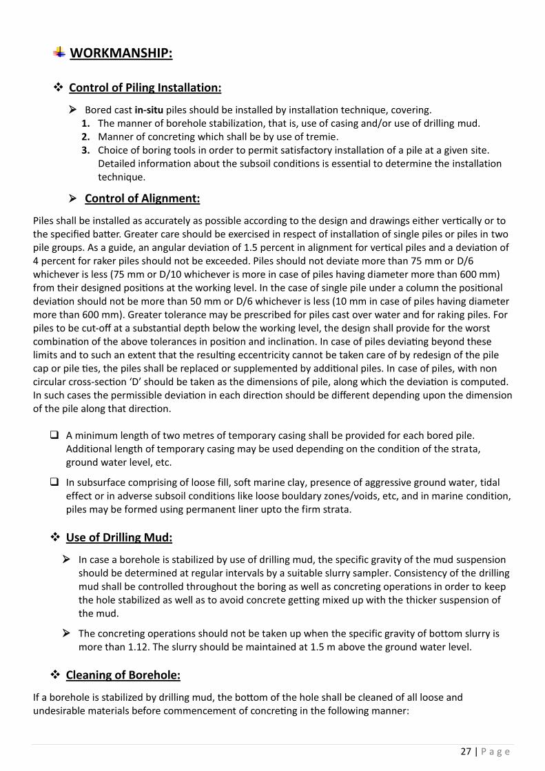
WORKMANSHIP:
Control of Piling Installation:
Bored cast in-situ piles should be installed by installation technique, covering. 1. The manner of borehole stabilization, that is, use of casing and/or use of drilling mud. 2. Manner of concreting which shall be by use of tremie. 3. Choice of boring tools in order to permit satisfactory installation of a pile at a given site.
Detailed information about the subsoil conditions is essential to determine the installation technique.
Control of Alignment:
Piles shall be installed as accurately as possible according to the design and drawings either vertically or to the specified batter. Greater care should be exercised in respect of installation of single piles or piles in two pile groups. As a guide, an angular deviation of 1.5 percent in alignment for vertical piles and a deviation of 4 percent for raker piles should not be exceeded. Piles should not deviate more than 75 mm or D/6 whichever is less (75 mm or D/10 whichever is more in case of piles having diameter more than 600 mm) from their designed positions at the working level. In the case of single pile under a column the positional deviation should not be more than 50 mm or D/6 whichever is less (10 mm in case of piles having diameter more than 600 mm). Greater tolerance may be prescribed for piles cast over water and for raking piles. For piles to be cut-off at a substantial depth below the working level, the design shall provide for the worst combination of the above tolerances in position and inclination. In case of piles deviating beyond these limits and to such an extent that the resulting eccentricity cannot be taken care of by redesign of the pile cap or pile ties, the piles shall be replaced or supplemented by additional piles. In case of piles, with non circular cross-section ‘D’ should be taken as the dimensions of pile, along which the deviation is computed. In such cases the permissible deviation in each direction should be different depending upon the dimension of the pile along that direction.
A minimum length of two metres of temporary casing shall be provided for each bored pile. Additional length of temporary casing may be used depending on the condition of the strata, ground water level, etc.
In subsurface comprising of loose fill, soft marine clay, presence of aggressive ground water, tidal effect or in adverse subsoil conditions like loose bouldary zones/voids, etc, and in marine condition, piles may be formed using permanent liner upto the firm strata.
Use of Drilling Mud:
In case a borehole is stabilized by use of drilling mud, the specific gravity of the mud suspension should be determined at regular intervals by a suitable slurry sampler. Consistency of the drilling mud shall be controlled throughout the boring as well as concreting operations in order to keep the hole stabilized as well as to avoid concrete getting mixed up with the thicker suspension of the mud.
The concreting operations should not be taken up when the specific gravity of bottom slurry is more than 1.12. The slurry should be maintained at 1.5 m above the ground water level.
Cleaning of Borehole:
If a borehole is stabilized by drilling mud, the bottom of the hole shall be cleaned of all loose and undesirable materials before commencement of concreting in the following manner:

28 | P a g e
A. Boring done with normal bailer and chisel with temporary/permanent liner — First heavier material to be removed with cleaning tools, such as, bailer and then reinforcement cage and tremie pipe to be lowered. Flushing then to be continued with water/drilling fluid under pressure through tremie pipe.
B. Boring done with bentonite slurry — Procedure given in (a) above to be followed. However, flushing shall be done with fresh bentonite slurry.
C. Boring done by rotary drilling rigs — cleaning bucket attached to the kelly shall be used for cleaning the bore. Wherever bentonite slurry is used, after using cleaning bucket, the bore shall be flushed with fresh bentonite slurry.
In case of flushing with water or bentonite slurry, the pump capacity shall be suitably decided depending on depth and diameter of bore so that sufficient pressure is built to lift the material up along with the fluid. Flushing should be continued till coarse materials cease to come out with the overflowing fluid. The finer materials will normally remain suspended in the fluid but they do not pose any problem. Alternatively, air lift technique may be used for cleaning of bore hole, if required.
Tremie Concreting:
Concreting for bored piles shall be done by tremie method. The following requirements are particularly to be followed for tremie concrete work:
A. The concrete should be coherent, rich in cement (not less than 400 kg/m3) and of slump between 150-180 mm.
B. The tremie should be water-tight throughout its length and have a hopper attached to its head by a water-tight connection.
C. The tremie pipe should be large enough in relation to the size of the aggregate. For 25 mm down aggregate, the tremie pipe should have a diameter not less than 200 mm. For 20 mm down aggregate, tremie pipe should be of diameter not less than 150 mm. All piling above 600 mm diameter piles, should, however preferably be done with 200 mm diameter tremie pipe.
D. A steel plate or a ball is placed at the bottom of the hopper and the hopper is filled with concrete. The first charge of concrete is sent down the tremie by removal of this plate or ball. Additional concrete is then added into the hopper and by surging action is pushed down the tremie and into the pile bore to the bottom of the pile. Theoretically, a small part of the first charge which gets contaminated is supposed to be the top of the rising concrete within the bore.
E. The tremie pipe should always be kept full of concrete and should always remain at least one meter into the concrete in the bore hole with adequate margin against accidental withdrawal of tremie pipes.
F. The pile should be concreted wholly by tremie and the method of deposition should not be changed midway to prevent laitance from being entrapped within the pile.
G. All tremie pipes should be cleaned before and after use.
H. A sliding plug of polystrene or similar material lighter than water and approved by the Engineer-in charge or his representative shall be placed in the tremie pipe to prevent direct contact between the first charge of concrete in the tremie and the bentonite slurry.
Normally concreting of the piles should be uninterrupted. In exceptional cases of interruption of concreting, it shall be resumed within 1 or 2 h, but the tremie shall not be taken out of the concrete. Instead it shall be raised and lowered from time-totime to prevent the concrete around the tremie from setting.

29 | P a g e
In case of withdrawal of tremie out of the concrete, either accidentally or to remove a choke in the tremie, the tremie may be introduced 60 cm to 100 cm in the old concrete and concreting resumed as mentioned before. The fresh concrete will emerge out of the tremie displacing the laitance and scum and prevent impregnation or laitance of scum in the fresh concrete.
The top of concrete in a pile shall be brought above the cut-off level to permit removal of all laitance and weak concrete before capping and to ensure good concrete at the cut-off level. The reinforcing cages shall be left with adequate protruding length above cut-off level for proper embedment into the pile cap.
Where cut-off level is less than 2.5 m below the ground level, concrete shall be cast to a minimum of 600 mm above cut-off level. For each additional 0.3 m increase in cut-off level below the working level, additional coverage of minimum 50 mm shall be allowed. Higher allowance may be necessary depending on the length of the pile. When concrete is placed by tremie method, concrete shall be cast up to the ground level to permit overflow of concrete for visual inspection or to a minimum of one metre above cut-off level. In the circumstances where cut-off level is below ground water level, the need to maintain a pressure on the unset concrete equal to or greater than water pressure should be observed and accordingly length of extra concrete above cut-off level shall be determined.
Defective Pile:
In case, defective piles are formed, they shall be left in place. Additional piles as necessary shall be provided.
Any deviation from the designed location, alignment or load capacity of a pile shall be noted and adequate measures taken well before the concreting of the pile cap and plinth beams.
While removing excess concrete or laitance above the cut-off level chipping by manual or pneumatic tools shall be permitted seven days after pile casting. Before, chipping/breaking the pile top, a 40 mm deep groove shall be made manually all-round the pile at the required cut-off level.
After concreting the actual quantity of concrete shall be compared with the average obtained from observations made in the case of a few piles already cast. If the actual quantity is found to be considerably less, the matter should be investigated and appropriate measures taken.
Recording of Data:
A daily site record shall be maintained for the installation of piles and shall essentially contain the following information:
1. Sequence of installation of piles in a group.
2. Number and dimension of the pile, including the reinforcement details and mark of the pile.
3. Depth bored (including depth in soft/hard rock).
4. Time taken for boring, concreting and empty boring, chiselling and whether the pile is wet or dry.
5. Cut-off level/ working level.
6. Sample bore log in the initial stage or when major variation occur.
7. When drilling mud is used, specific gravity of the fresh supply and contaminated mud in the bore hole before concreting shall be recorded regularly.
8. Any other important observation.

30 | P a g e
PILE CUT OFF, EXCAVATION AND CLEAN-UP:
Pile Cut off Level:
A. All Piles shall be concreted up to a level of 1200 mm above the Specified Pile Cut Off elevation which shall be 75 mm above the bottom of the pile cap.
B. Before casting the pile cap, this excess concrete shall be chipped off up to Pile Cut off elevation by Civil Construction Agency. In case, sound concrete is not met with at such elevation, the piles shall be cut to such elevation where sound concrete is met.
C. Piles shall be cut off at level and true to elevation shown or specified in the drawings. Care shall be taken not to damage the reinforcement or the Concrete below cut off elevation during such stripping operations.
D. Where stripping has been done to a level lower than the specified Cut off Elevation to obtain dense and sound concrete, the Contractor shall built up the pile up to Cut off Elevation at their own cost.
Excavation:
A. Excavation by the Contractor for Pile Cut off shall be done to the depth Specified on the drawings. These excavations shall be co-ordinated with the Engineer-in-charge, so that they will remain open for a minimum possible time and the pile cap concrete is placed as soon as possible thereafter.
B. Any additional excavation carried out due to pile stripping being required to be carried out below the cut off elevation to obtain dense Concrete and the backfilling of all such excavation shall be done by the Contractor at his own cost.
Cleaning of Work Site:
A. Upon completion of the pilling work, all casing equipment. Construction Tools. Protective coverings and debris resulting from the piling operations shall be removed from the works site with the permission of the Engineer- in-Charge.
B. All excavated material and left over drilling mud shall be disposed off as may directed by the Engineer-in-charge away from the site and the cost of all such clean-up operations shall be included by the contractor in his Rates for piling work and no separate payment will be made for the same.

31 | P a g e
REQUIREMENTS OF DRILLING MUD (BENTONITE):
PROPERTIES:
The bentonite suspension used in bore holes isbasically a clay of montmorillonite group having exchangeable sodium cations. Because of the presence of sodium cations, bentonite on dispersion will break down into small plate like particleshaving a negative charge on the surfaces andpositive charge on the edges. When the dispersionis left to stand undisturbed, the particles becomeoriented building up a mechanical structure of itsown. This mechanical structure held by electricalbonds is observed as a thin jelly like mass ormembrane. When the jelly is agitated, the weakelectrical bonds are broken and the suspensionbecomes fluid again.
FUNCTIONS:
The action of bentonite in stabilizing the sides of bore holes is primarily due to thixotropic property of bentonite. The thixotropic property of bentonite suspension permits the material to have the consistency of a fluid when introduced into atrench or hole. When left undisturbed it forms a jellylike membrane on the borehole wall and whenagitated it becomes a fluid again.
In the case of a granular soil, the bentonite suspension penetrations into sides under positivepressure and after a while forms a jelly. The bentonite suspension then gets deposited on the sides of thehole and makes the surface impervious and imparts aplastering effect. In impervious clay, the bentonite does not penetrate into the soil, but deposits only asthin film on the surface of hole. Under such condition,stability is derived from the hydrostatic head of thesuspension.
REQUIREMENTS:
The bentonite powder and bentonite suspension usedfor piling work shall satisfy the following requirements:
1. The liquid limit of bentonite when tested, shall be400 percent or more.
2. The bentonite suspension shall be made bymixing it with fresh water using a pump forcirculation. The density of the freshly prepared bentonite suspension shall be between 1.03 and 1.10 g/ml depending uponthe pile dimensions and the type of soil inwhich the pile is to be bored. The density of bentonite after contamination with deleterious material in the bore hole may riseup to 1.25 g/ml. This should be broughtdown to at least 1.12 g/ml by flushing beforeconcreting.
3. The marsh viscosity of bentonite suspension when tested by a marsh cone shall bebetween 30 to 60 stoke; in special cases itmay be allowed up to 90 s.
4. The pH value of the bentonite suspension shall be between 9 and 11.5.
Re use of Circulated Bentonite Slurry:
While boring in continuation, the fresh suspension gets contaminated with bored spoil and gradually becomes heavy.
This contaminated Bentonite may be re used depending upon the manner of boring, type of strata encountered and the specific gravity of the Contaminated Bentonite.
It is essential to check the specific gravity of the Bentonite Slurry in the bore holes before re using.
The contaminated Bentonite Slurry may be collected in a suitable receptacle and allow the heavier particles to settle down and the SLURRY shall be washed before reuse.

32 | P a g e
KENTLEDGE DIAL GAUGE
CHISEL
HYDRAULIC PUMP
BAILER
RIG (TRIPOD WITH WINCH)

33 | P a g e
CASING
DMC PIPE
COVER BLOCK
REINFORCEMENT
Testing pile

34 | P a g e
HYDROMETER
CONCRETE MIXING MECHINE
TRIMEI PIPE HOPPER
TOTAL STATION
TOTAL SITE VIEW

35 | P a g e
Conclusion:
Bored Cast in situ piling is favourable than other piling processes. Because there is no waste of time and materials so it is economical and can be cast into exact length. It can bear heavier load and transfer it to the ground soil. Also the transportation cost is not high.
It is not necessary to reinforce the pile in normal cases or in places where the pile is completely submerged in the soil. But for more stability and durability of structure we use reinforcement. Over all, Bored cast in situ is preferable for bearing huge amount of load as it can be cast deep inside the ground.


![Pile Foundation Design[1] - ITDmtp.itd.co.th/ITD-CP/data/PileFoundationDesign.pdf · Introduction to pile foundations Pile foundation design Load on piles Single pile design Pile](https://img.dokumen.tips/doc/110x75/5a6ffb387f8b9ab1538b8376/pile-foundation-design1-itdmtpitdcothitd-cpdatapilefoundationdesignpdfpdf.jpg)