Embed Size (px)
Citation preview

REPORT
ON
ENERGY PERFORMANCE EVALUATION
AND OPTIMISATION IN PULP & PAPER
INDUSTRY
SUBMITTED TO
CESS GRANTS AUTHORITY(DEVELOPMENT COUNCIL FOR PAPER, PULP & ALLIED INDUS]
BY
CENTRAL PULP AND PAPER RESEARCH INSTITl
SAHARAN PUR, U. P., INDIAWWW. cppri .org.in

REPORT
ON
ENERGY PERFORlVIANCEEV1~LUi\TIOl~ND OPTIIVIIZA TION IN PULP & P~;\PE
INDUSTRY
SUBi\IITTED TO
CESSGRlc\NTS l\-UTHORITY(DEVELOPMENT COUNCIL FOR PAPER. PULP & ALLIED IXDUSTR
BY
CENTRAL PULP AND PAPER RESEARCH INSTITUlSAHARANPUR., U. P., INDIA
,,\\w.cllpri.org.in

Project
Objective
Dsration
Research Team
Technical Advisor
Principal Investigator
Associates
Project Profile
Energy Performance EvaluatiOptimization in pulp andIndus: ;'Y
-To improve energy efficiencypaper manufacturing.
-To reduce energy costs, whilemaintaining consistent produquality
August 2001 to June 2004
Dr. A.G. KulkarniDirectorCentral Pulp and Paper RInstitute Saharanpur, U. P., 111
Dr. R. M. lVlath!1TScientist E-IIChemical Recovery &Management Division
Dr. B. P. Thapliyal, Scientist EShe Sanjay Tyagi, Sc. BShe Suneel Dixit, TO BShe Alok Kumar Goel, Sc.BShe Arvind Jain, SRFShe Veererwka K.Bhorale, SRI

TABLE OF CONTENTS
Contents Page No.! Executive summary 1I Chapter-II Background 7I Objective 8i Introduction 9: Status of Indian paper industry 9: Energy consumption pattern 11i Chapter-Z: Activities Under Taken 15t Methodology 15: Details of industrial Partners 26Large Wood Based Pulp & Paper iVlills 27Agro Based Pulp & Paper Mills 41Waste Paper Based Pulp & Paper Mills 47Expertise Gained & Infrastructure Created 62
Chanter-JObservations & Recommendations 67Large Wood Based Pulp & Paper Mills 67Aaro Based Pulp & Paper ~Iills 103Waste Paper Based Pulp & Paper Mills 128
Chapter-sConclusion 144List of Paper ;\Iills - Annexure - (Section wise saving potential carried out at different mills-Annexure - IIComprehensive Questionnaire for i\'1iI1Data & Information -Annexure - HI
EXECUTIVE SUMMARY

ENERGY PERFORMANCE EVALUATION ANDOPTIMIZATION IN PULP & PAPER INDUSTRY
EXECUTIVE SUMMARY
GENERAL INTRODUCTION:Pulp & Paper Mills are large and complex facilities consuming en:
quantities of steam & electricity. The industry is under pressure to
energy consumption to become cost competitive in the open econor
globalization. At the same time there is public demand for improving I
quality and reducing green house gas emissions. In view of these and
energy crisis, the industry has made important strides for reducin
energy use and increasing the Cogeneration through self generated b
sources. The pulp & paper industry has been more effective in re
steam demand than electricity demands in new and retrofitted mills
new and modernized plants use less energy than old plants. For in
state of art bleached Kraft pulp mills in the U.S. use about 40% less
and 5% less electricity than typical mills installed in the 1980' s. The
Pulp & Paper Industry on the other hand, is traditionally large consu
energy and is yet to achieve sizable reductions in energy consumptioi
is a challenging task particularly due to the complex structure of Indiar
industry. Therefore industry needs to adopt structured programr
achieving the energy efficiency targets for its sustainability. 1
performance evaluation of the paper industry is a specialized job and
services of experts. Based on the evaluation of energy performance, if
can suitably optimize its unit operations and processes. Realizing the n(
energy efficiency in pulp and paper sector, CPPRI and NCBM initi
project study under cess-funded schemes. The report highlights achieve
of this study.

The energy team during its studies collected data on operating pararnet
study the process efficiency and suggested various optimization measur
increasing the efficiency level.
The report prepared is divided into three main chapters. In chapn
following areas have been covereJ:
a.) Background:
The high energy consumption in Indian mills is due to various factors
as mill integration, its design, processes & equipments in addition to th
materials and product mix, capacity utilization & size of the plant.
absence of modernization has also resulted in poor energy efficiency (
Indian mills. Besides this, the lack of energy efficient process technok
lack of energy monitoring & reporting is also one of the reasons for
energy consumption. In many mills un-optimized process operations wi
energy accounting result in Jarge amount of energy wastage, which ce
trapped by following simple measures thereby saving considerable ener]
b.) Status Of Indian Paper Industry:
Paper industry is one of the energy intensive sector, ranking 6th am
the high energy consuming industries in India. Indian Paper Indu
consumes 4 million tonnes of coal and 2 million MWh of purch:
energy. Out of the total energy requirement of the pulp & P:
production, 75-85% energy is used as process heat and 15-250/.
electrical power. More than 40 % of the electricity and more than 3
of the fuels consumed is cogenerated or recovered.
c.) Energy Consumption Pattern:
The consumption of energy in Indian mills varies, depending on
mill integration, its design of processes and equipments, raw materi:
products, size of the plants etc. Looking into wide variation in enei

consulllPtion in different categories of mills, energy norms h
setup for these mills as given below *;
Particulars Steam, tit Power, KWhJLarge paper mills 9.00 1400Newsprint mills 4.70 2000Medium & small agro mills 5.75 1200Small waste paper based mills 2.80 700
* ClI Report on Specific EnergI) Consumption Norms in Indian 1Paper Industry (1996-97)
However, the energy consumption figures are much higher in tl
than the set norms. The high cost of excessive energy used by 1
the Indian mills makes the economic evaluation of conse
measures reasonably straightforward for cost effective productir
In chapter - 2 following areas have been covered:
a.) Methodology:
A planned methodology was adopted for executing the activitiesthe project as
• Collection of data through questionnaire
• Mill visits
• Data collection & evaluation
b.) Details of industrial partners:
Energy Performance Evaluation and Optimization Studies If
selected Pulp & Paper Mills (Listed below) were carried 01
critically evaluate the energy generation, distribution and consumj
patterns in various sections. Based on these studies, recommendai
have been submitted to the mills to enhance their' energy efficienc)

LARGE WOOD BASE;.) PULP AND PAPER MILLS;
1. ,Mis Seshasayee Paper & Boards Ltd. Erode (T.N.)
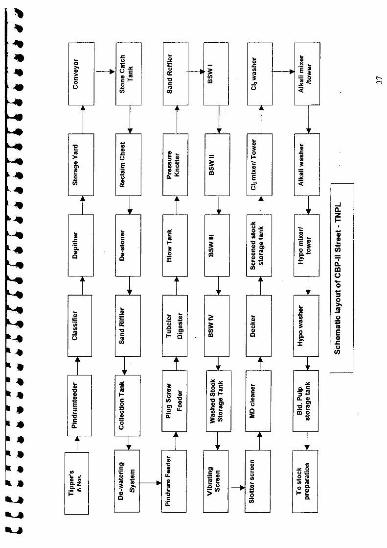
2. Mis Tamil Nadu Newsprint & Paper Ltd., Distt. Karur, (T.N.)
3. Mis BaIIarpur Industries Ltd. (BIL T), Unit: Ballarpur, Distt. Chandrapur (Maharashtn
4. Mis Ballarpur Industries Ltd. (BIL T), Unit: Shree Gopal, Yarnuna Nagar (Haryana)
5. Mis The Sirpur Paper Mills Ltd., Sirpur - Kaghaznagar (A.P.)
AGRO BASED PULP AND PAPER MILLS;
6. Mis Shreyans Industries Ltd., Ahemadgarh (Punjab)
7. Mis Kailash papers, Unit: Kailash Papers Ltd., Aghwanpur, Distt. Moradabad (U.P.)
8. Mis Yash Papers Ltd., Darshannagar, Faizabad (U.P.)
WASTE PAPER BASED PAPER MILLS;
'. Mis Kalptaru Papers Limited, Tal. Kalol, Gandhinagar, Gujarat
O.MIs Well Pack Papers & containers Ltd., Varnaj, Tal. Kalol, Gujarat
1. MIs Rainbow Papers Limited, Ahmedabad, Gujarat
2. MIs Karan Paper Mills, Chhatral, District - Mehsana, Gujarat
3. Mis Shelavi Pulp & Paper Mills Pvt. Ltd., Chhatral, District - Mehsana, Gujarat
L MIs Plaza Papers Pvt. Ltd., Village Ghunna, Behat Road, Distt. Saharanpur (U.P.)
4

c.) Expertise gained & infrastructure created:
During course of the project, CPPRl developed expertise in the
electrical, thermal and process auditing in different categories
and paper mills like large wood based pulp & paper mills, agn
pulp & paper mills and waste paper based pulp & paper IT
constituting a dedicated enerav audit team of scientists and eng]"-' '-~ •....
Under the project activities following equipments have been pl
to strengthen the Enerzv Management Division of the institute.•..... .......; '-'
1. Motor Top along with transducers -Portable equipm
motor and pump efficiency analysis
11. Energy Auditor-portable equipment for evaluation of el.
parameters
Ill. Flue gas analyzer- Portable equipment for the measurer
O2, CO2, CO, NOx, SOx and Hydrocarbons
IV. Non Contact Thermometer- for the temperature measu:
at various uninsulated surfaces
v. WinGEMS 5.0 Computer simulation software for ener
material balance studies
VI. Computer Systems - for data analysis and documentatior
vu. LCD-for presentation and information dissemination
energy audits
Based on the audit studies carried in different categories of pulp ane
mills, recommendations submitted to the mills have been covered in (
-3. The mills have implemented most of the recommendations.
The studies have been useful to identify areas where improvement can be mr
implementation of recommendations have resulted in overall savings of en
the tune of 7-10%. The mill managements have appreciated the studies cor

under the project activities. :'\. large number of energy saving options have also t
identified during the project studies. The energy saving proposals cover all secti
of the mill for pulp and paper production.

REPORT
ON
ENERGY PERFORMANCE EVALUATI(AND OPTIMIZATION IN PULP & PAP}
INDUSTRY

CHAPTER-l

REPORT
CHAPTER -1
BACKGROUND:Paper Industry is one of the highly energy intensive industrj
consumption of energy is considerably higher in Indian paper indus
compared to developed countries. On an average, energy inputs con
more than 25% towards cost of production. The energy cost cornpor
today dictating the cost of production and the Indian paper industry is
tough challenge of competition in the "Global Market".
The high energy consumption in Indian mills is due to various factors s
mill integration, its design, processes & equipments in addition to tl
materials and product mix, capacity utilization & size of the plant
absence of modernization has also resulted in poor energy efficiency
Indian mills. Besides this, the lack of energy efficient process techno
lack of energy monitoring & reporting is also one of the reasons for'
inefficiency. In many mills un-optimized process operations without
accounting result in large amount of energy wastage, which can be t
by following simple measures thereby saving considerable energy.
Studies conducted by CPPRI during last decade have revealed that t
potential to save upto 15% energy in Indian pulp & paper mills by fol
simple energy management practices. Adopting energy mana]
practices in a paper mill is a well-planned programme with actions ai
reducing the organization's energy bills & minimizing the detri
environment effects.
Indian pulp and paper industry has taken up large number of initiatives
energy management programmes to reduce the energy consump
However the efforts made by the mills are not adequate to embark upor
complete energy management drive within the sector. As a result the mil
India still consume higher amount of energy compared to mills in devek
countries. Therefore looking into energy consumption pattern and signifi
effect of energy inputs in the cost of production, Central Pulp and P
Research Institute (CPPRI) along with National Council for Cement
Building Materials (NCBM) initiated the project on "Energy Perform:
Evaluation and Optimization in Pulp and Paper Mills" funded by C.
Grants Authority to check out an energy efficiency programme for the 1
and paper industry.
This proposal was made with the intention of studying the ene
performance of paper industry. By improved energy management practi
the energy efficiency of paper manufacture would be improved resultin,
reduced cost of production. The study was planned to carry out the diagno
energy audits of the representative paper units covering wood, agro, wr
paper and newsprint grade mills and to identify main areas of ene
wastages in various sections & measures for minimizing the energy los
and improving energy efficiency.
OBJECTIVE:
The main objectives of the study are to:
1. Improve energy efficiency in paper manufacturing.
2. Reduce operating energy costs, while maintaining consistent product quality.
The energy audit studies ware carried out in 14 mills of different ca
and the results have shown remarkable saving potential upto 5 to 15(:
energy consumption.
INTRODUCTION:
STATUS OF INDIAN PAPER INDUSTRY:
The paper industry has an important role to play on Indian economy
rising demand of pulp & paper products has made India a large
therefore various International suppliers are willing to step in. The p
paper sector is one of the complex industrial sectors with diversity
material, variation in scale of operation and utilizing old technology
Indian pulp and paper industry consists of about 618 paper mills, m:
small and medium size which are based on obsolete technologies
uneconomical when compared with the mills of developed countries. "
a growing need to invest, thus capital is needed for mill modern
productivity improvements and building of new capacity.
Among the three segments based on raw material usage in the paper ir
the mills based on forest raw material. are slowly moving t
competitiveness through adequate modernization over the years des]
fact that these mills are old and still a significant proportion of paper i
is yet to undertake modernization programs.
The agro-residue based segment has only a few mills complying with
& environmental requirements, whereas large number of units une
category do not have proper technology to produce quality produc
competitive price. This segment is also having serious environ
pollution problems due to lack of chemical recovery systems. Major

or this segment requires modernization and up-gradation in order to bee
competitive.
The third segment, i.e. based on recvcled fiber also has a number of s~. .pulp & paper mills, which are based on obsolete technology. One of
major concern of these mills is lack of adequate equipment for processin
recycled fibers and as a consequence, the quality of paper products prodi
from these mills are not conforming the national standards.
competitiveness of this segment without modernization and up-grada
would be difficult.
Paper industry is one of the energy intensive sector, ranking 6th among
high energy consuming industries in India. Indian Paper Industry consurm
million tonnes of coal and 2 million M\Vh of purchased energy. Out of
total energy requirement of the pulp & Paper production, 75-85% energj
used as process heat and 15-25% as electrical power. More than 40 % of
electricitv and more than 30~·'O of the fuels consumed is cogenerated
recovered.
In India, most of the small & medium paper mills rely on purchased power
looking into the cost constraints. mills are switching to the internal ener
generation facilities. The internal energy generation is mainly frc
cogeneration by generating steam from boiler at high pressure & utilizing tl
in steam turbine for generation of power. The steam extracted in the form
low S: medium pressure is utilized for the process requirements.
The fuels used in boiler are mainly coal, lignite, rice husk, sawdust & oth
agro residues, while the coal is main fuel for large pulp and paper mills. TI
solid fuel consumption per tonne of paper varies from 1.5 to 2.5 tit.

ENERGY CONSUl\tIPTION PATTERN:
The consumption of energy in Indian mills varies, depending on t
integration, its design of processes and equipments, raw materials, pr
size of the plants etc. Looking into wide variation in energy consum]
different categories of mills, energy norms have been setup for these 1
shown below *;
• ClI Report an Specific Energy Consumption Norms in Indian Pulp and Paper 1(1996-97)
Power ConsumptionNorms for Indian Mills
2500 .,----------.-----,
2000 +----
~ 1500
~ 1000
500 -
oLarge paper mills
.fa Newsprint mills!I10Medium & smallI a <Tl"O millsI r,'i! 0 Small waste papeI~sedmills
Steam ConsumptionNorms for Indian Mills
o Large paper mi
10 ~--------------------------~
8 +----'
.•..l:' 6 -+---Q
E-< 4 -+--_
2+--o -L-.:.,;,,--
o Medium & smaagro mills
• Newsprint mill
oSmall wastepaper based mi

However, the energy consumption figures are much higher in the mills tl
the set nonns. The high cost of excessive energy used by most of the lnd
mills makes the economic evaluation of conservation measures reasona
straightforward for cost effective production.
The energy consumption pattern of Wood and Agro based mills in a f
selected mills is shown below. The figures show that there is wide variat
in energy consumption among the mills.
Wood basedPower consumption, per ton of paper
2000 - 1739 1742
500 -
11681390
f?ll.~,~.i!:
12341500 +;
~ 1000-~
SIRPUR SILT-SAL TNPL SILT-SG
14
12
10c:
80---c: 60-4
2
0SPS
Wood basedSteam consumption per ton of paper
13.33
SIRPUR SILT-SAL TNPL SILT-SG
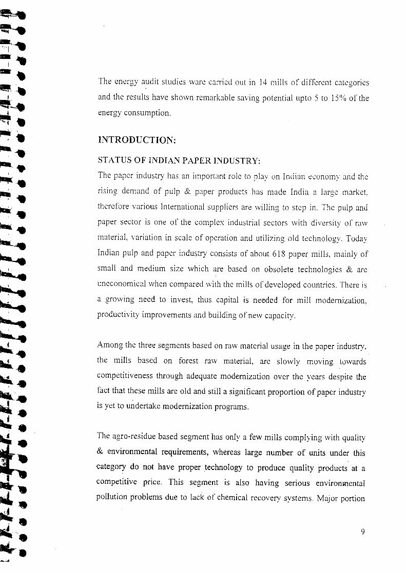
Agro basedPower consumption, per ton of paper
1200 1152
300
1025
900
s:~ 600~
595
Kailash Shreyans Yash
Agor basedSteam consumption, per ton of paper
8
7"
7.5
4.5
Q) 6 j
a.~5o 4co- 3 Jc.£ 2
4.3
1 -i
Io -l-!~-''-
Kailash Shreyans Yash
Implementation of energy management programmes in mills of d
categories with different sizes, different raw materials, products, mill
design of processes & equipments etc. is quite difficult. A 1
methodology cannot be applied in all the mills for energy mana

activities. Studies were conducted during the project implementati
representative mills to find out the areas with maximum saving potentia
studies in mills covered wide domain of activities such as good managi
practices, good house keeping, analysis of process parameters, process
energy efficiency analysis, evaluation of energy consumption ill
equipments and sections, at site energy efficiency monitoring etc.
The study helped to improve energy management practices in some se:
mills of different categories as well as to identify main areas of e
wastages in various sections and to suggest measures for minimizin
energy losses for improving energy efficiency. Some of the particij
mills contributed upto 50% cost for conducting the studies under the pr
The major activities undertaken during the project period are highlighi
next chapter.

CHAPTER-2
CHAPTER - 2
ACTIVITIES UNDERTAKEN:
lYIETHODOLOGY:
A planned methodology was adopted for executing the activities under the
Major activities were:
1. Collection of Data Through Questionnaires:
A questionnaire was prepared to obtain details of mill processe:
materials. chemicals and products. These questionnaires were sent
mills after they agreed to participate in the project study. The dai
evaluated at CPPRI and from the information: energy consumption pat
mill and various processes was determined. The data colleen
questionnaires was useful for the energy team as first hand informatic
from the information available detailed plan for the mill visits was
The copy of the questionnaire is enclosed as Annexure -III.
2. xrm Visits:
The visits to the mills were undertaken after confirmation of dates fra
mills. The audit team comprised of scientists & engineers from CPPF
NCBM. The team carried portable equipment/instruments for data coll
and monitoring of process variables in the plant. The duration of mil
was upto 5 days during which team interacted with the mill managem
shop floor personnel and conducted plant studies.
3. Data Collection & Evaluation:
Relevant data was collected during the mill visits and studies conduc:
plant to evaluate and find out the system efficiency in the plant. Folk
areas were covered during the mill visit.

• Raw material storage. handling and preparation
• Digester House - Cooking of raw material- -• Washing. screening & cleaning of unbleached pulp
• Bleaching section
• Stock preparation
• Chemical additives
• Paper machine
- Wet end
- Pressing & drvinz...... • b
• Finishing &. converting
• Chemical recovery
- Black liquor evaporation
- Recover. boiler
- Causticization
• Power House
- Power boilers
- Co generation
- DG - Sets
• Steam distribution and consumption in different sections / processes
• Electrical energy management
- Electrical load management
- Electrical distribution
- Status of major motors in the mill
- Status of major pumps in the mill
Details of the activities undertaken by the energy management team in above
listed areas. is presented below for large. medium & small mills.
16

3) Raw Material Storage:
_ Details of storage yard losses including the mode of storage of logs I
and time of storage.
_ Finding out the extent of degradation of the raw material celh
content during the storage. The raw material samples collected from
were analvzed at CPPRl laboratories to find out the extent of dezrac- ~
in the raw material storage yard.
b) Handling of Raw Materials:
_ Mode of transportation of logs from the storage yard to the chipper
and determination of its efficiency.
_ Suggestions for suitable transportation alternatives, if possible.
c) Raw Material Preparation:
_ Analysis and evaluation of the preparation of wood (debarking:
material preparation including chipping and chip classification.
_ Evaluation of opportunities for energy savings in the wood prep,
area by optimization of chippers. The energy team during the ~
looked into the chipper operations critically w.r.t.;
• Proper feeding of the raw materials
• Type of chippers, capacity and running hours.
• Knife arrangement in the chipper i.e., their numbers, aligi
changing frequency etc.
• Chip collection mode
• Dust collection and utilization
The team also looked into the quality & uniformity of the chips pn
during the visit. The opportunities for energy saving in the wood prep
area, indirectly linked with the quality & uniformity of the chip:

evaluated. The study team tried to find out the ways to improve the c
quality for;
• Better utilization of the digesters through better packing
• Reduced cooking time
• Reduction in rejects
• Simplification of the pulp cleaning systems thereby reducing 1
energy requirements.
d) Pulping:
- Evaluation of chip storage, conveying and feeding mode to the digesters
- Evaluation of the cooking chemicals to the digesters such as;
• Strength
• Chemical characterization
• Temperatures etc.
- Evaluation of other inputs to the digester such as steam and black Iiqu
for dilution etc.
- Optimization of cooking conditions in terms of active alkali, time
temperature, steam consumption etc. so as to reduce the ener]
consumption while maintaining the pulp quality for bleaching.
- Energy team looked into various opportunities for energy saving in tl
pulping of raw materials. Some of the points evaluated for energy savinj
in chemical pulping were;
• Possibilities to reduce the liquor to wood ratio In the digeste
provided that yield and quality are maintained. The lower the liquor 1
wood ratio, the lower the steam consumption for a certain set (
operational conditions.
• Increase the temperature of white liquor, using waste heat available i
the mill and by insulation of storage tanks.

• Feeding of chips, cooking chemicals etc.
Blow heat recovery- the audit team has also found out the possibi
blow heat recovery, if not practiced in the mill. Alternate utilizat
also suggested for use of energy from blowing of the batch digeste
mill.
e) Washing of Pulps:
The washing efficiency determines the steam load in evapor
chemical recovery and chemical losses during washing. SCI
improvement of the washing efficiency was studied by optimiz
dilution during the pulp washing.
The dissolved organics carryover with the pulp and the soda loss
evaluated and its impact on the bleach section was quantified.
t) Bleaching:
Most of the Indian mills use chlorine based bleach chemicals. C
bleaching sequences are CEH and CEHH. Some large mills (
chlorine dioxide and peroxide partially i.e., CEpHD. Audit sr
concentrated its efforts in this field for optimization of b
parameters so as to reduce the chemical and energy consurnptioi
bleaching operation.
Impact of optimization studies leading to environmental benefits 1
carried out.
g) Stock Preparation:
Stock preparation is one of the major power consuming areas in pal
making processes. The energy efficiency during refining is influenced
the type of refining equipment and its configuration. During audit stud.
following possibilities were explored to reduce the energy consumption.
- Control pulp consistency to the optimum levels.
- Control of pulp inlet & outlet pressures.
- Evaluation of alternate disc pau.ems.
- Utilization of more energy efficient refiners.
h) Paper Machine:
The paper machines consume high quantities of steam & power ar
constitute 30-35% of the mills energy requirement. The high specific eners
consumption of the paper machine is due to practice of old convention
methods of papermaking. These includes head box, slice, foil, table rolls ar
machine clothing. which produce low consistency web. Low consistenc
forming increases evaporation loads on the dryers. Press section is also ver
conventional in most of the mills. Paper machine mostly have partial close
dryers section. Condensate recovery ranges between 60-90%.
During studies these processes were critically evaluated for their efficiencj
Some of the points for energy audit studies are narrated below;
i. Reduce paper breaking - Paper-breaking leads to wastage of energ:
and reduced yield. Improved understanding of the process, efficien
equipment design and better instrumentation controls can minimize it
Stud" team looked into optimization of processes to reduce pape:
breaking.
2C

II. Improved removal of sand and foreign substances in the a11
flow systems - :\ systematic study of the pulp screening bet
box was undertaken tl) find out its efficiency and best practicwere suezcsted to improve it.~~
Ill. Study of the formation section (Fourdriener or double
Suggestions have been given for improving the formatir
conJucting a detailed study of the wire part. An Increase
consistencv of the paper neb before its transfer to the press il
resistance of the paper sheet to breaks and reduces the paper mo
the web after press section.
iv. Study of the press section - A detailed study of the press sect
been mack and suggestions were given to improve the out let pal
consistency and improve dewatering efficiency in the press secti
main factors affecting the removal of water in the press section, a
below. have been looked after;
• Nip pressure
• Uni form distribution of the pressure in cross direction
• Type of press. its configuration and no. of nips.
v. Options for increase in temperature of the paper sheet by
steam shower on the press have also been evaluated for irnj
dewatering by reducing the viscosity of water.
. vi. Improvement in.the drying of the sheet by increasing the heat tr
in the steam cylinders. It can be achieved by reducing the resi
posed during drying by reducing condensate layer thickness by pre
removing condensate from the cylinder. The study of condensai
removal assembly has been made for determining its condensa
removal efficiency.
vii. Utilization of the flash steam leaving the dryer with condensa
(Blow-through Steam). The condensate recovery system in pap
machines were studied and possible improvements were suggested f
effective utilization of flash steam in some of the dryer groups.
viii. Pocket ventilation system to remove the build up of humidity in tl
pockets between the dryer cylinders.
ix. Hood ventilation system for improving paper drying. Study of tl
economizer heat recovery system in the paper machine.
x. Study of the recycling of white water has been evaluated case by cas
i) Recoverv Section:
Large niills in India are equipped with chemical recovery systems. Durii
energy audit studies black liquor evaporation, incineration in recovery boil:
causticizaiion and lime reburning operations have been evaluated.
Evaporation of black liquor: The steam consumption 10 evaporate
dep~nds OIl some operational variables such as solid content and temperate
of weak black liquor. solid content of the strong black liquor a.
pressure-vacuum in the evaporators.

Following points have been evaluated for energy savings in evaporate:
• Increase of the solid content of weak black liquor from w
Optimization of the washing operation in the pulp mill leads to i
in percent solid content of the weak black liquor. Studies or
saving by optimization of washing operation have been conducte
• Temperature of the weak black liquor - During the stud)
liquor storage has been evaluated for maintaining the high tern]
of the black liquor feed to the evaporators. An increase
temperature of weak black liquor can result. in considerabk
economy in the evaporators.
• Solids content of the Strong black liquor - Possibility for inc
the solids content of the strong black liquor for higher
efficiency of the boiler has been evaluated.
• Possibility of increasing the number of effects in multipl
evaporators - In many mills in India direct contact evapora
being used in the finisher stage. During the studies, effect (
contact evaporators was evaluated and alternative ivlEE
suggested with financial analysis.
a. Recovery Boiler - During the studies, the team evaluated t1
design and operating parameters and subsequently suggestic
given for:
1. Selection of proper primary, secondary and Tertiary air.
ii. Black liquor characteristics, which can affect the cor
behavior etc.

b. Causticizing:
The recausticizing process was evaluated considering production
clean and hot white liquor and suggestions were given to improve
caustisization efficiency.
j) Power House:
Efficiency Evaluation of boiler by conducting a detailed survey of bo:
operation, which includes;
• Boiler details - Type of Boiler, designed capacity (t/hr), feed wa
flow rate, steam pressures, fuel consumption etc.
• Fuel analysis
• Bottom Ash Analysis
• Flue gas analysis
Optimization studies in the boiler by conducting a simulation exercise for:
• Maintaining optimum excess air level
• Optimization of blow down
• Waste heat recovery by use of heat recovery systems, if not existing
• Performance evaluation of existing heat recovery systems
• Reduction of radiation and other structural losses.
k) DG Sets:
The DG sets consist of two main sub systems:-
• An Internal combustion engine (Most frequently, a compressic
ignition one) and
• An alternator
While conducting an energy audit it is the engine or the prime mover par
which is concentrated upon. Some conservation options for fueJ an
lubricating oil usage in the DG set have been considered, such as;
• Assessing the operating efficiency of the DG set in terms of
(Specific Electricity Generation Ratio) with the unit of kWh/li:
figures, which are computed, have been compared with the no
figures supplied by the DG set manufacturer. Efforts have bee
to identify the cause of lower SEGR of the sets.
• Proper engine loading was determined. The drop in ef
becomes fairly pronounced at loads below 60% and this re
energy losses.
These activities were sufficient to assess the overall enerzv efficiency~", "'
and paper mills. Based on the results of the study a large no. of IT
were suggested for improvements and are discussed in the next sectioi
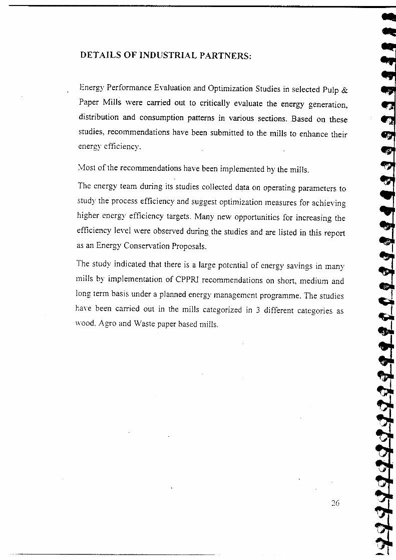
DETAILS OF INDUSTRIAL PARTNERS:
Energy Performance Evaluation and Optimization Studies in selected Pu
Paper Mills were carried out to critically evaluate the energy general
distribution and consumption patterns in various sections. Based on tl
studies, recommendations have been submitted to the mills to enhance t
energy efficiency.
Most of the recommendations have been implemented by the mills.
The energy team during its studies collected data on operating parameter
study the process efficiency and suggest optimization measures for achiev
higher energy efficiency targets. Many new opportunities for increasing
efficiency level were observed during. the studies and are listed in this reJ
as an Energy Conservation Proposals.
The study indicated that there is a large potential of energy savings in m:
mills by implementation of CPPRI recommendations on short, medium j
long term basis under a planned energy management programme. The stue
have been carried out in the mills categorized in 3 different categories
wood, Agro and Waste paper based mills.

LARGE, WOOD BASED PULP AND PAPER lYULLS
Energy performance evaluation and optimization studies were conduc
following wood based mills:
1. l\tI/s Seshasayee Paper and Boards Ltd., Erode, T.N.,
The study on energy performance evaluation and optimization was co
at Mis Seshasayee Paper & Boards Ltd., Erode (TN). from 14.5.:
19.05.2001 and 04.11.2003 to 06.11.2003.
Mis Seshasayee Paper & Boards Ltd., Erode is a leading firm unde
Group of Companies, located at Erode (TN). The mill was establi
1960. Commercial production was started in the year 1962 with collal
of Parson & Whittmore, South Asia, USA for a production cap.
20,000 tpa. As on today, mill produces 1,15,000 tpa paper an:
utilizing bagasse, casurina, eucalyptus hybrid, waste paper and impon
as main raw materials. Mill produces a wide range of products
machines viz. writing and printing papers, multi layer duplex, boa
packaging papers. Mill has three pulping streets for producing
chemical pulp (110 tpd), hard wood chemical pulp (110 tpd) and I
paper street (80 tpd). The mill has 3 chippers, 4 stationary dige
continuous digesters, 3 washing -sections, 4 power boilers, 3 turbo ge
and 2 recovery boilers.

I Outside Bagasse r-H Tank
1 1Remer
1 1SlushingI 'I 1 "-I
I Ponni Bagasse f-,ir
I I~ I ConvevorI r Pin Feeder
l r Aqua SeparsScrew Feeder I.•.• I I I I 1
,Ir
I Pandia Digester 1I Blow tank
1 1 Knorters1 1
BSW 4 Sta""l I "'-1 I "-I..,Tllh•••
.1,Sec. Centrifufal I ~ I lI
Pri. Centrifufal 1Centricleaners I '/'r ••••n f"'" I '/'r ••••n r" I Washed Stoc
Cb., J I +I I Screened Stock I 1 1Thickner I I rh•.er r ""l Chlorine Mixer I "1 Chlorine Tow
"I Hvpo Tower I I Washer I I Caustic Tower
I r WasherI I ~ I I I
'---_\_\'_as_h_e_r_...J---~~IBleached Stock
y
Schematic Layout of Pulp Mill (Bagasse Street)Seshasavee Paper and Boards Ltd.

Rechipper
Wood
WoodOscillating
Screen
I Knottersl Blow Tank1-" 2 Nos.
y
I I•.. Washed
BSW 4 Stage Stock
St. Digester ~>----C
Pri. CentrifufalScreen
Ch
I Chlorine Mixer I.l- Screened StockChest
~_~~_T_hi_c_~_e_r_~~~~----C=
I Chlorine Tower 11--_-l~~IL-_w_as_h_e_r_...JII----i•.~ I Caustic Tower d---l"~ [
___ w_a_s_he_r I"'~I----IHypo Tower II ~ I Washer· I~~I----"-:~
Bleached Stock
Schematic Layout of Pulp Mill (Hard Wood Street)Sesbasayee Paper and Boards Ltd.
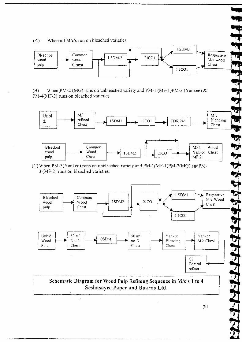
(A) When all M/c's run on bleached varieties
Bleachedwoodpulp
ISDM3CommonwoodChest
I SDM-2
I leal
(B) When ]>M-2 (MG) runs on unbleached variety and PM-l (MF-l )PM-3 (Yankee) .PM-4(MF-2) runs on bleached varieties
Unbld.w{\(vl
MFrefinedChest I TDR24" 1--
Ar-Bleached Common MFIwood Wood I I I ~.1COI : ' Yanke~ ISDM2pulp Chest
.. ,MF2
(C) When PM-3(Yankee) runs on unbleached variety and PM-l(MF-I)PM-2(MG) andpJ\3 (MF-2) runs on bleached varieties.
rISDMIBleached Common
Iwood ~ Wood ISDM2 ~JCOIpulp Chest •••
lJJCOJ (I
50 m; 50 m;r-
Unbid. Yankee YarWood )\0. ~ no. 3 Blending M/(Pulp Chest Ch~st Chest
C3Controlrefiner
Schematic Diagram for Wood Pulp Refining Sequence in Mlc's 1 to 4Seshasayee Paper and Boards Ltd.

From CBP+WPStockprepar- CWPation
ColourClayWhltenmg
BlendingChest
Machine CRChest
Controlrefinin2
ConstantlevelboxCy 3.5-4% Consistency
regulator
Cy.25%
.----~y.17-1 B~Wire Cy.. 3-0.5~l Cy.O.3-0Ao/. 3 sta
Press Pressurized~
Se lecti fier cenn.---- Part ~ Part ~ ~head box screen syste1 no.
'---Suction press
,ir
rl Reels
M.G Cy95~ Pope•.. Dryer with •.. ~iRewinder ~•.. •.. reel2 no. hot pressroll
SheetCutter
L-t
Process flow block diagram of Paper Machine-3 (Yankee Mlc)Seshasavee Paoer and Boards Ltd.
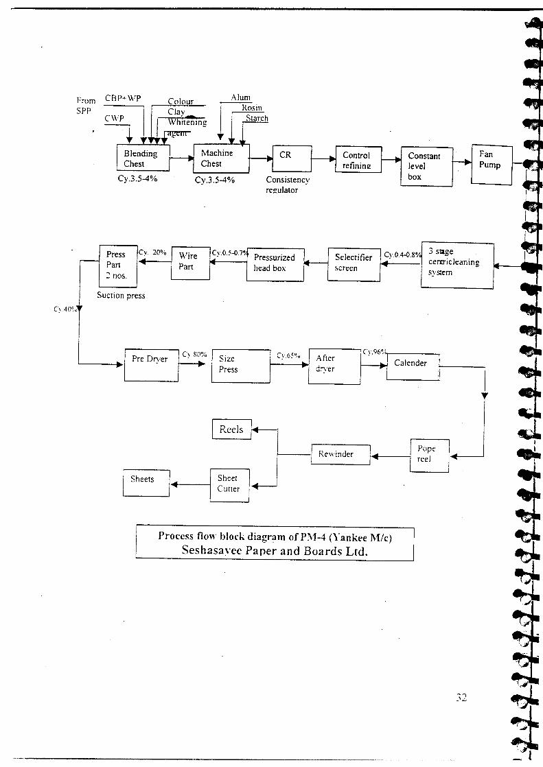
From CBP+\VP ColourSPP Clav
CWP ..•.~
Whitening
T
Blending Machine CR ConstantChest Chest level
Cy.3.5-4% Cy.3.5-4% Consistency boxregulator
3 stagePress Cy 20~o Wire Cy.O.5-O.7° Selectitier Cy.O.4-0.8%.. Pressurized~ cerzrich.-- Part ...•
Part r" head box ...•screen sysern2 nos.
Suction press
C~ 80% Cy.96~·Size Cy.65°/~ After Calender Ii~ ...Press •. dryer ..
q
:!
Pre Dryer
I Reels r-L I~Rewinder I~ PopeJI reel
~~SheetCutter
Process flow block diagram of P\1-4 (Yankee M/c)Seshasavee Paper and Boards Ltd.
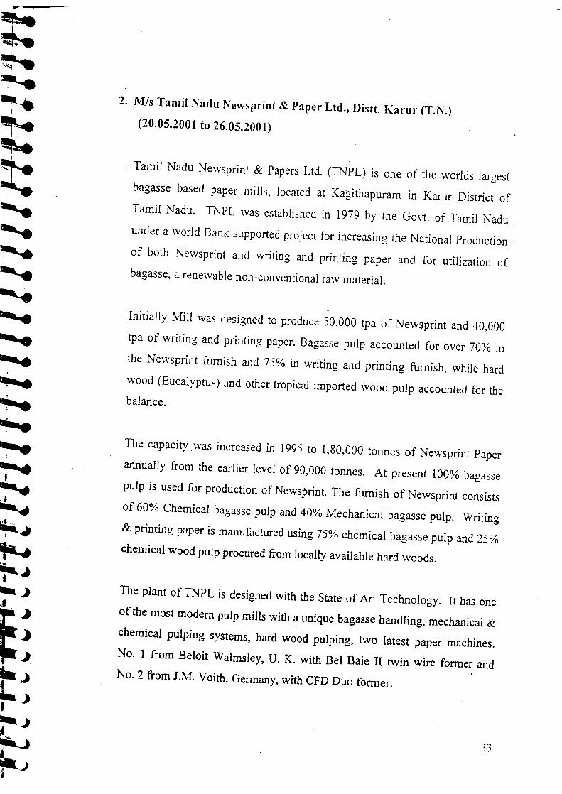
2. Mis Tamil Nadu Newsprint & Paper Ltd., Distt. Karur (T.N.)
(20.05.2001 to 26.05.2001)
Tamil Nadu Newsprint & Papers Ltd. (TNPL) is one of the worlds
bagasse based paper mills, located at Kagithapuram in Karur Dis
Tamil Nadu. TNPL was established in 1979 by the Govt. of Tam
under a world Bank supported project for increasing the National Pro
of both Newsprint and writing and printing paper and for utiliza
bagasse, a renewable non-conventional raw material.
Initially Mill was designed to produce 50,000 tpa of Newsprint and
tpa of writing and printing paper. Bagasse pulp accounted for over ~
the Newsprint furnish and 75% in writing and printing furnish, whil
wood (Eucalyptus) and other tropical imported wood pulp accounted.balance.
The capacity _was increased in 1995 to 1,80,000 tonnes of Newsprint
annually from the earlier level of 90,000 tonnes. At present 100% bs
pulp is used for production of Newsprint. The furnish of Newsprint co
of 60% Chemical bagasse pulp and 40% Mechanical bagasse pulp. W
& printing paper is manufactured using 75% chemical bagasse pulp and
chemical wood pulp procured from locally available hard woods.
The plant of TNPL is designed with the State of Art Technology. It ha
of the most modern pulp mills with a unique bagasse handling, mechanic
chemical pulping systems, hard wood pulping, two latest paper mach
No.1 from Beloit Walmsley, U. K. with Bel Baie II twin wire former.No.2 from 1.M. Voith, Germany, with CFD Duo fanner.

The mechanical bagasse' pulping has two stage pressurized primary refit
and atmospheric secondary refining system. Mill has 2 streets of 6 et
LTV evaporators with FC concentrators, and one street 7 effect falling :
black liquor evaporation plant. Concentrated black liquor is fired on
recovery boilers of 285 and 375 tpd BLDS with steam generation of 35 1
and 45 tIhr. @ 44 kg/crrr' pressure and 440°C temperature. Mill is equip
with 4 power boilers having 60 t/hr. steam generation capacity at 44 kg/:
pressure and 440°C temperature and one power boiler having 90 tIhr. stc:
generation capacity at 44 kg/em' pressure and 440°C temperature, three tu
generators having 8 MW, 18 Mw and 10.5 MW capacity. Water intal«
from River Cauvery through a 4 Km. pipe line.
TNPL produces quality Newsprints like standard Newsprint (49 gsm) h:
brightness Newsprint, Pink Newsprint etc. Its writing & printing pap
include telephone directory paper, computer stationary paper, SS maplitl
offset printing paper, Cream wove paper, super printing etc.
The Company has recently introduced photocopier paper with brand nar
TNPL copier.
3

III0)o
't:Jos
o(f)
•..I--------~==~----~~0r--- ~ >.
CII>c:oU
•..o.~CII 0
tJ~tJCO
~CO
eCIICII•..o
(f)
•..CII0.,e-J:U
...Qi.Q•..o>.CII>c:oU
f
•...o::l
.go
.~
•..tJCII
~ '(i)a::
•..CII0.0. J:...~+-.!.. ~~ 0
-
~
't:J0.I-..,MIIICIIe
u..
r---.~J:tJc:a..
•
't:J0.I-
~,..
•..CII...IIICII0)o
~c:"'...
c:CIICIICII•..tJIII•..CII......oc:~
=
0. •.•_ C1I::l ~0.0'0;ClIO)
s: "'III •.•
"'03:;;;
a. •..::l CIIa.~o'0'"CII CIIc 0)
CII "'CII ••••.•0tJ •••en fI)
•
•..CII.:..:oCIIc
III•..CIIc:CIItJ:::c:CIIU
eCIIC1I•..tJfI)•..CII•...2
en
•..CII~o-
•..C1IJ:fI)
"'s
o
•..CIIsoI-..:;<U
,
•..CII)(
E
.•..CIIJ:III
"'~o0.>.:I:
•..C1I
o ~a.B>.-'::
:I:C1I,~E
'ZCDJ:co"'~o0.>.J:

•...0>-Q)
>=0o
.~."0•..C'CI>-Q)
ClC'CI•..0...•en
...1!::=0.Q)
a
to
...Q)
::rJlrJlC'CI
U
~
...III"0IIIIII...E
I] IyI
~rJl •••• IIIIII 0o.z0.i=<.P
- no-
uC'CIoXo =III C'CI=~0-en
~,-rJl •..III Q)-= :;::o ....
Q)
E ~~ "0
=() C'CIQ) en~
r
•.. oXIII == C'CI0 ~- ~IIIIII .2Cl co
~
•..Q) •.. •..:;::.... III IIIa: - ...•
III III.0 III
"0 :3 .~= ~aC'CIen
~oX
~=I'll III •••~ ••• III
()"Oe en III0 Cllll::; :3LJ...() Ia:III
0 IoII.
•..III
Cl "0
= III.;: E IIIQ) III
LJ...- - EI'll III~ >- :3III en •..
"0a =0..
Solenco
•..- ~v;~ '"en ~a:l N
:..J
,r
oX oX()= •..o I'll IIICi)~ ~"0 III 0III Cl ~
.:: C'CI NrJl •••C'CI£~en
,..
Cl •..- = IIIIII )(- III -I'll•.. •.. -.0 () ..;<
::;en o
- oX()oX
Q) o -III - -•.. rJl C'CI() -rJl "0 III•.. Q) Cl
2 - C'CIQ) •..- Q) 0E .......
en () rJlen
,r
•..III= •..C'CI IIIIII
oX()
o Ill"
a a:E
I
... IIIIs ,0
I...•C'CI
oXC'CI
"•..IIIJ:IIII'll
~C'CI
oX
;;:
-•..III)( •..E IIIs0 00.->-::z:
,r...III.::IIIC'CIs00.>-::z:
~
oX0.=_ I'll:3-
0.. IIICl
"0 I'll- ...CD0-rJl
~r
=~ou:.;::::o C1J........III C1J00.~ ~0.
..Ja.zI-
I.•..(l)(l)....•..II)
Ia.CDo-o.•..:::lo>.~o
:;:;~E(l)s:oen
..0>.G)>c0o
~~
'a..ca>G)0'1I!0-en
~~
..G).c-'CoG)c
,,..
..G);;';II)ca(3
I..G)
'aG)G)-E=..'aCi:i:
ien~.. .,;G) Q~z
.- IQ••••
.c ..G)U e- -ca.llC G) H ~c c 0:::
G) ca enct- 'a m0 c- caen en
~jl.
'r ,r
-II)G)G) ••.c =o •• G)
== ~E g: 0'; G) C en(j a:~ mG)0::: .~
,r ,Ir
.. .lICG) CC ca -0 t- ~- ~II) enIG) 0 mc iii
.~,Ir ,.
..G) ..e ..
~G) G)-ii: Q; II) ~.a G)'a = 0'1 enc t- o mcaen
t +r.lIC .lIC.lIC
~ U CC o caca G) .. 0•...t- .. G)Uc en 'a 'aG)G)0 0'1 G) G)en:; .cl!U = LL II) 0.! a:: ca_'0 ~enc
~jl.
+ ,Ir..G)
en '0c G) 0'1''::: E G) c cG) G) LL ,- G)- - E
-G)ca II) •.. I! ••~ >. ~ ::s .aUI en - .- en
Q) " >c ci:i:
..G).cenca~
..G) ..~ G)0 .c
•••• II)ca1:: ~G)
)( fti'§ .lICN «(3
.lICU.lICo C-ca(1)-'0 G)G)enc caG) ••G) 0..-U II)en
..G).lICUG)C
..G)ccaG)(jc:E
cG)
euII)..~en
1::G),~ ..E ;o 0Q,->.:I:
..G).cII);oQ,>.:I:
.lICQ,C
- ca=-Q.G).en
'Oca- ..m.sII)
C.lICOu:;o ca- ..en cao Q,
~!Q,
3. MIs Ballarpur Industries Ltd. (BILT), Unit: Ballarpur,
Chandrapur (Mabarasbtra)
(27.04.2003 to 03.05.2003)
MIs Ballarpur Industries Ltd. (BILT), Unit: Ballarpur, is located at Ball:
District Chandrapur, Maharashtra, 200 km from Nagpur. The av
production of the mill is 116269 mt against the installed capacity of ~
tonnes per annum. The main raw material is hard wood and bamboo i.
ratio of 55:45. mill produces writing & printing paper of different grade
quality on six nos. of paper machines. The mill has 10 nos. stationary
digesters, Brown stock washing section, Bleaching section (CDEopH
four power boilers (two running) and three turbines.
The present energy consumption of the mill is given below
1. Electrical energy consumption, kWhIt of paper = 1168
2. Steam, tit of paper . = 8.4
3. Fresh water consumption, mJit of paper = 142
4. MIs Ballarpur Industries Ltd. (BILl), Unit: Shree Gopal, Yan
Nagar (Haryana)- .
. (28.07.2003 to 06.08.2003)
MIs Ballarpur Industries Ltd. (BILn, Unit: ShreeGopal is locatetI -
~~~,~~Clg~'J~~.~a). The average production of re mill is 75,000against'thc"inStalled'eapacity of53,000.tonnes per annum.' The main
',,' . "it~i">t:X\~'*V'\";I;'" I -
material is hard wood and bamboo in jlte ratio of 84:16. Mill prod~ ;
writing & printing paper of different grades and quality on six nos. of p
machines. The mill has 3 nos. stationary batch digesters, Brown s

washing section, Bleaching section (CDEoDID2), five power boilers (1
running) and two turbines.
The present energy consumption of the mill is given below
4. Electrical energy consumption, kWhlt of paper = 1235"S I t/" f (E.l1du.nGrt£Ul) 1t~qrnuDf;i8"'3'~5. team, t 0 paper ': _ ' ",' = .
6. Fres'h water consumption, m3/f~fp~p~f\'\01U:O~J·{~r'f90
5. Mis The Sirpur Paper Mills Ltd., Sirpur - Kaghaznagar (A.P.)
(25.08.2003 to 30.08.2003)
MIs The Sirpur Paper Mills Ltd. Is located at Sirpur - Kaghaznagar (A,
The average production of the mill is 77,974 MT against the insta
capacity of 83~550 tonnes per annum. The main raw material is hard w
and mill produces" writing & printing, Packaging', board and specialty pa
of different grades and quality on seven nos. of paper machines. The mill
14 nos. stationary batch digesters, Brown stock washing section, Bleach
section (CEpH)H2), Eight power boilers (three running), two recovery boil
and four turbines.
The present energy consumption of the mill is given below
7. Electrical energy consumption, kWhit of paper = 17428. Steam, tit of paper
9, Fresh water consumption, m3/t of paper
= 13.33
= 193
L
AGRO BASED PULP AND PAPER iVlILLS
Energy performance evaluation and optimization studies were cond
following agro-based mills;
1. Mis Shreyans Industries Ltd., Ahemadgarh (Punjab)
(27.08.2001 to 31.08.2001)
Mis Shreyans Industries Limited, Unit: Shreyans Paper, Ahmadg:
leading firm under Oswal Group of Companies, located at Ahr
(Punjab). The mill was established in 1982. Commercial production st
1984 with production of 30 tonnes per day. As on today, mill prod
tonnes paper per day utilizing wheat straw, bagasse, sarkanda gra
caddies and imported waste paper as main raw materials. Mill p
writing and printing paper with one machine. The mill has ten
spherical digesters, one continuous digester, washing and bleaching
four power boilers, a turbo generator and the Enders fluidized bed rea
recovery of inorganic pulping chemicals.

_______ 2.....JHH Y pow ash er -2 H __ H_D_t_o_w_e_r_...JH'- C_h_e-,st
rTPulpto
stock preparation
Che st ssw - 2
Dilution tank
ssw - 4 ssw - 3
Chlorine tower'---J'hlorine washe
Hypo tower A Ika Ii was her
~ Thickener H Centicleaner Hibratory
Schematic diagram of Pulping/bleaching StreetShreyans Industries Ltd.

2. MIs Kailash papers, Unit: Kailash Papers Ltd., Aghwanpu
Moradabad (U.P.)
(13.06.2002 to 15.06.2002)
MIs Kailash papers, Unit: Kailash Papers Ltd. is located at
Aghwanpur.l J'" km east from Moradabad - Dhampur road. Initially
was promoted by Dhampur Sugar Mills Ltd., for the manufacture
kraft paper in year 1977 with an installed capacity of 30 tonnes p
day. The capacity was upgraded to 50 tonnes per day in year 1988
management was taken over by Mis Kailash Papers Ltd. in Decemb
As on today, mill produces 50 - 55 tonnes of Kraft paper per day by
Bagasse and Wheat Straw as main raw materials and 15-16% imj
indigenous waste paper. Mill produces kraft paper of 22 BF in the
80 GSM to 210 GSM, on one fourdriner paper machine. The mill has
spherical digesters, brown stock washing section, one power boiler a
sets. There is no bleaching section and chemical recovery secti
schematic diagram of the plant is given in·below.

Through hrough
lbelt belt 12' Digesterconveyor conveyor 4 Nos.....•..
wmllcriaJ Depither L Blow tank Febrilizeryard ~ No.1 4:2 f-+ I ~ I
ssclwhw I 14' Digesteruraw 4 Nos.
.,r
l. Screen I Hot chest TOR Hot chest No. PorcherNo.3 21" 1&2 ~...• ......- ...•
,.:>Ccker BSWNo.I&2 H.D.Tower Cycling Chest TOR~ No. :2 •. 21'·~ .. ~
••n Pump I~ Machine chest Mixing Chest Mixing Chest Cycling Chest
No.I&2 No.2 ~ No.1 No.1I...• ...• ...• I...•
~.ad Box Wire Press Part Dryer Pope Reel~ •.. •.~ .. •.
,.iading Godown Packing Small Reels Rewinder~ ~I ...• ...• ...•
T
Schematic Diagram of Plant - Kailash papers
44

3. MIs Yash Papers Ltd., Darshannagar, Faizabad (U.P.)
(23.06.2003 to 26.06.2003)
Mis Yash Papers Ltd. is located at Darshananagar, about 10k
Faizabad (U.P.). The mill was established in 1983 with an initial cat
1940 MT of Kraft Paper per annum based on waste paper. Capacity el
from 1940 TPA to 3010 TPA with addition of gunny & bagasse pulp
in the year 1984. Further capacity enhanced from 3010 TPA to 4000
the year 1989. Mill has set up unit-2 with an installed capacity of 60
to manufacture kraft paper in the year 1991. Under Modemizat:
expansion programme the capacity increased from 4000 TPA to 6000
unit 1 and from 6000 TPA to 10,000 TPA of unit 2 in the year 1995
today the capacity of the mill is 16000 MT per annum and mill produ:
45 tonnes of kraft paper per day by utilizing 75% bagasse as ill<
material and 20% gunny and 5% waste paperlKCB. Mill produces kra
and super deluxe in plain & ribbed of 20-100 GSM. The mill has ~
spherical digesters, 3 power boilers, one. 2.5 MW. Turbine & and t
paper machines. The mill is self sufficient in power. There is no bl
section and chemical recovery section.
Present Energy Consumption is given below:
(i) Water Consumption, m3/tp : 12a-:.140
(ii) Steam Consumption, tltp : 4.5 .
(iii) Electricity Consumption, KWhltp : 900.:-1150.. I~
.. . IThe schematic diagrams of both the units are given below
-: II

Throughhell
Raw material conveyorHydra Pulper Pulper Sand Trap I I TurbI I
I "'I "' Storage ReflerI "'Irh••~
M/c Chest JNos
ant level~ox
Through.,..- ...,TDR Refining
Chest
Fan Pump Primal')'Centricleaner
Sh~, C",'a t-1 RC_elS_---lI. I,-_Re_\\'i_nd_er---,~
PorcheBNi Washing
PressureScreen
Dryers
___ PO_p_e_R_e_e_'__ /-r------
Schematic Diagram of Plant - Yash Papers Ltd.

WASTE PAPER BASED PAPER MILLS
Energy performance evaluation and optimization studies were cond
following Waste based mills;
1. l\tl/s Kalptaru Papers Limited, Tal. Kalol, Gandhi Nagar, Cujarai
(29.01.2002 to 31.01.2002)
NIls Kalptaru Papers Limited is a leading firm located at Tal. Kale
Gandhinagar. The mill was established in 1990 and commercial pre
started in 1990 with the production capacity of 10 tonnes per day.
today, mill produces about 30 tonnes of Newsprint and 60 tonnes At
Kraft paper per day by utilizing imported and indigenous waste p
main fibrous raw materials. Mill produces Newsprint and Absorbei
paper with two machines.

Throughbelt
conveyor
,3W materMII Pulper I Pulper chest j Higll density , Turbo..cleaner "- separator•. rl 1 P' I •.
C)' 3%
Refiner Chest
~rschine chest Refined stock ~ Refiner ~ Thickner chest Thickner !<IIIchest ....• .....•
c, 3-3.5%
rnstam level Fan pump Primary' •.. 1 Pressure ... Head boxbox
•.cenmcleaners ..-, screen P'
0.9-1.0",.
)SI dryer ~ t-t G. dryer I~...•
93-44~'o
Pre dryer Press (2 No) I'" I Wire pan I.I...----- 27% 1-~ __ I
Talender
~1L..__ p_(lp_e_r_ce_'_.•.. ~,-I__ R_e"_'I_nd_e_r_
Flow Diagram of Paper Machine No.1 - Kalptaru Papers Ltd.
48

Throughbelt
conveyor
Raw material Pulper Pulper chest High density _J Turb..cleaner separa
,. ,."'"I
NDLKC, Krattpaper waste,OCC, mixed
paper & boards
Refiner Chestr ~I Machine chest ~ Relined stock Refiner Thickner chest ~ Thicknchest ...• -..
Cy 3-3.5%
,Ir
Constant level Paper machinebox ~
No.2
Cy 3-3.5%
Pulp Street for the manufacturing of absorbent grade paper on Pl\IKalptaru Papers Ltd.
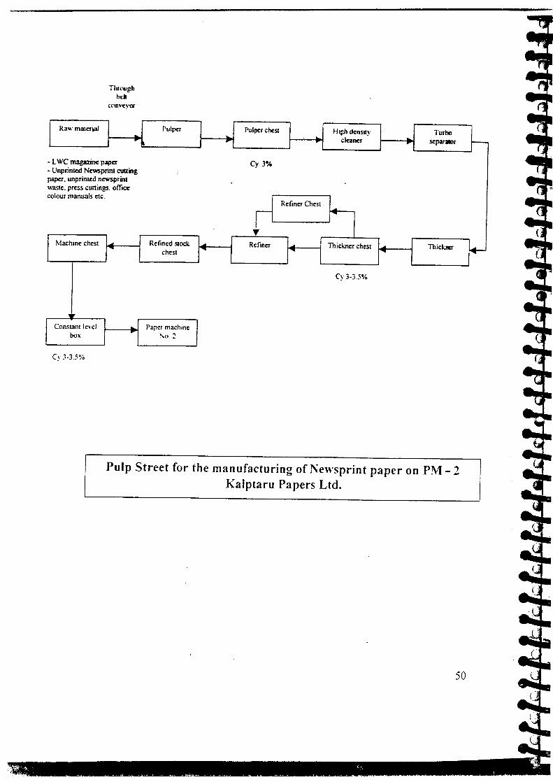
ThrClll!,!bbdt
con\~\-or
3'" marerjai I J Pulpcr I J Pulper chest Hll,!hdensuy Turbo•..cleaner ~I "'-1 I -, •. scparalr
C magazine papermnted Newsprint cuuing• unprinted newsprint. press cuttings. office
Cy 3%
r manuals CIC.
Refiner Chestr ~
achme chest .. Refined stock ..• Refiner I..• Thickner chest ~ ThickllCl'"'" chest "'"
/"'" ~
Cy 3-3.5%
ir
nstant level Paper machinebox •.
~o. 2
Pulp Street for the manufacturing of Newsprint paper on PM - 2Kalptaru Papers Ltd.
5C

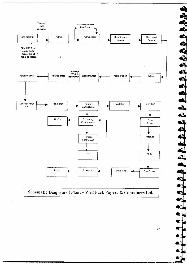
2. Mis Well Pack Papers & Containers Ltd., Vamaj, Tal. Kalol, GUj:
(02.02.2002. to 04.02.2002)
Mis Well Pack Papers and Containers Limited is located at village Va
km west from Mehsana high way road with an installed capacity of
tons/annum. The project came into production on 16 November 1995
today, mill produces about 43 tonnes of Kraft paper per day by l
imported & indigenous waste paper as main raw materials. Mill pl
Kraft paper of 16 BF to 28 BF in the range of 100 GSM to 220 GSM,
fourdriner paper machine.
Throughhell
.~ Sand Trap ~conveyor
••~aw matenal I I Pulper I J Pulper chest I High dens I!)' HorizontalI
I "'-1 I ...-, cleaner Screen.~DLKC. Kraftpaper waste.OCC,mixed .
)apcr & boards
e-
lachine chest ~ Mixing chest TDR& Refiner Chest ~ Thickner chest ~ Thickner~ ••• UUI' ~
1ronstant level Fan Pump
"'- Primary Head Box Wire Panbox I r'
Centricleaner •. •..
~ I~
Thicker Secondary r- Press~CentricJeaners 3 Nos.
~ 1Ternary f--
~
Centriclears
I
Throueh
M.G.
___ R_C_e1_S_---'I. IL__ R_CI_"_In_d_cr_--1Pope Reel Post Dryers
Schematic Diagram of Plant - Well Pack Papers & Containers Ltd.,
3. Mis Rainbow Papers Limited, Ahmedabad, Gujarat
(05.02.2002 to 07.02.2002)
Mis Rainbow Papers Limited is a leading firm located at Ahmedab:
mill produces about 80 tonnes paper per day of different varieties.
utilizing wide variety of waste paper both indigenous and imported g
the production of duplex and other varieties of papers. The Importee
are hard white cuttings, soft white cuttings, envelop with window c
super mIX mixed waste paper, mechanical cuttings (newsprint), N
oee etc. Indigenous grades are; white cutting, note books, Cl'U
records, Lee, bottom layer duplex cutting, text books, mixed cutting
cuttings, paper tubes etc.
Paper machine No. 1 & 2 are multi cylinder mould machines producin
38 t/day and 25 to 30 t/day respectively. PM-3, a fourdrinier machir
yankee dryer produces M.G. poster.
The mill has two boilers, one supplied by Mis Thermax, Pune and ott
supplied by Par Techno (Ahmedabad).

MIDDLE LA YER I I ROTTOM'.A YFnTOP r.A \,F:R
Convevor
I•••
TDR ChestIY 1+TDR
•••Chem icaJ Chest
I•••
I 1\1iddle Chest
Pulp Mill No. I & II For Duplex Board - Rainbow Papers Ltd.
5·

Conveyor Sand Trap PIT
Thickner
Potcher TDR Chest TDR
M/c Chest
Pulp Mill No.3 For G Poster - Rainbow Papers .•..td.
• .•.•..-...." .•.. --
.• ~ ...•.

4. ~s.Karao Paper Mills, Chhatral, District - Mehsana, Gujarat
-" (15:4.2003 to 16.4.2003)
MJsKaran Paper Mills is located at Kadi - Kalol Road, Chhatral, Distri-"¥.!
Mehsana, G~jarat. As on today, mill produces 45-48 tonnes of Kraft Pal
-~~.•••• Media (B grade), Ribbed Super Deluxe, Ribbed Kraft, Poster White,
Newsprint by utilizing waste papers like imported OCC, indigenous O(
sack kraft, white ~utting and newsprint as main raw materials. Mill produ
Kraft paper of 14-28 BF in the range of 100 GSM to 160 GSM, on two Iv
paper machines.
•••
5

Raw material .1 II; dr:! Pulper1 Sand Trap I High density Turbo
cleaner ..-, -, , - r
, tImpOCC,lndOCC, Sack Kraft.Trims, Neesprint
Rejects
"No.5 chest J \1(\ ·1chest TOR
No 2 Chest ...• No. I Chest ~ Thick,~I ~ ~ ""
JMachine Chest I1 Wire P.
rolls IConstant level I Head Box SuctionFall Pump ..•. Primary .. No. Bag:box -[ ~ Ccntricleaner - r f\,
Throuah
SecondaryCcntrrcleaners
TertiaryCentriclears
PitPredry.
M.G.
'---_R_C_e1_S__ 1 ~ 1....._R_e_w_in_de_r_I .•••~t---'--_P_OP_e_R_ce_I_~
Schematic Diagram of Plant - Karan Paper Mill

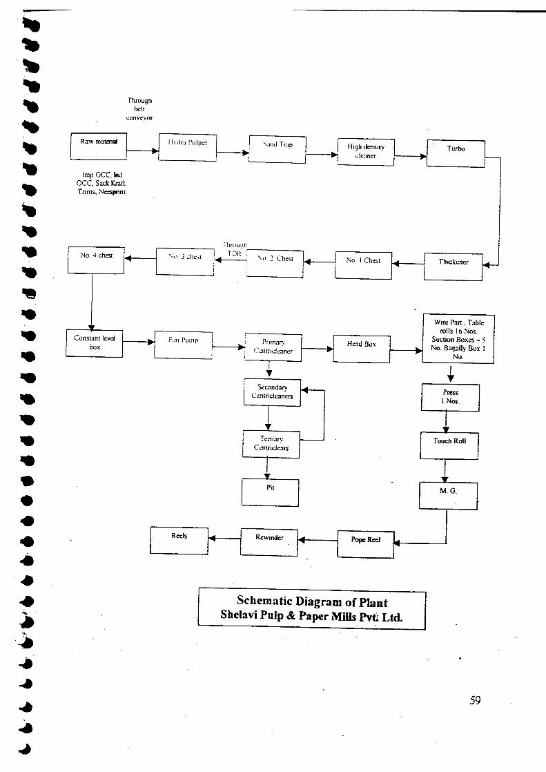
s. MIs Shelavi Pulp & Paper Mills Pvt. Ltd., Chhatrai, District - Mehsana
-Gujarat
(17.4.2003 to 18.4.2003)I
MIs Shelavi Pulp & Paper Mills Pvt. Ltd. is located at Kadi - Kalol Roar
Chhatral. District _ Mehsana. Gujarat. As on today, mill produces 15 tonne
of Kraft paper. media (8 grade). ribbed super deluxe, ribbed kraft, posn
white and newsprint by utilizing waste papers like imported OC(
indigenous acc, sack kraft. white cutting and newsprint as main ra
materials. Mill produces Kraft paper of 14-18 BF in the range 0[60 GSM·
150 GS\1. media (8 Grade of 12 BF in the range of 60 GSM to 120 GS~
ribbed super deluxe in the range of 40 GSM to 80 GSM, poster white in tl
range or 32 GSM to 46 GSi\1. ribbed kraft in the range of 44 GSM & :
GSM and newsprint in 39 GSM on one M.G. paper machine.
Throughbelt
Raw matcm& , II Ivdru Putper S.llld Trap I High densrty~ ~',I______ ,..'- ~!---;~.'_. 1---- cleaner
Imp OCC.1ndOCC, Sack Kraft.Trims, Nc::sprint
NO.4 chest I \,) J chest Il I
Constant level I Fan Pump Ibox ~I I
Turl
____ N_'O_._IC_h_c_st_'~ 1'-__ Th_l_ck_.e
Wire Palrolls I
: Suction E, Prunarv .•.. Head Box ....•. No. Bagai Ccntnclcaner r ,
N.
c=Rewinder . '~~r---.....,r--Po-pc-Ree-'-rr--__ I
I'Y
SecondaryC entricleaners
Pit
,--_R_ec_ls_~I~
PressI Nos.
Schematic Diagram of PlantShelavi Pulp & Paper Mills Pvtf Ltd.
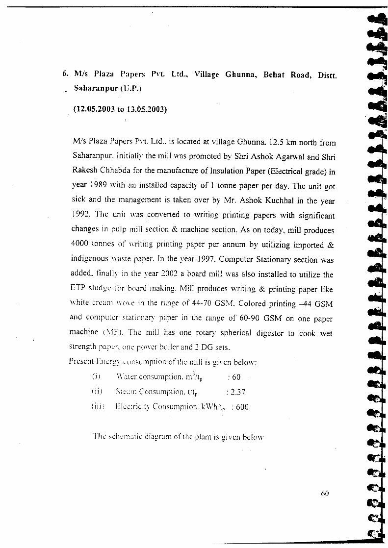
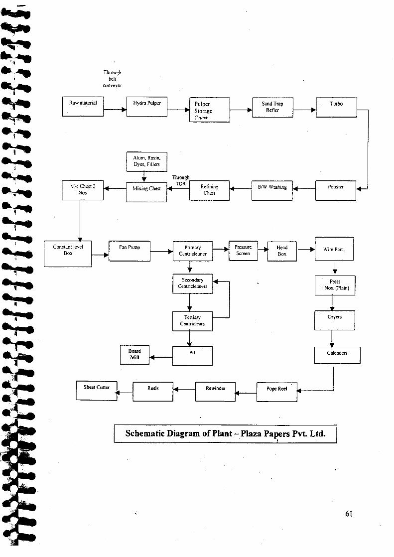
6. Mis Plaza Papers Pvt. Ltd., Village Ghunna, Behat Road, Di
. Saharanpur (V.P.)
(12.05.2003 to 13.05.2003)
Mzs Plaza Papers Pvt. Ltd .. is located at village Ghunna, 12.5 kin north fn
Saharanpur. Initially the mill was promoted by Shri Ashok Agarwal and S
Rakesh Chhabda for the manufacture of Insulation Paper (Electrical grade)
year 1989 with an installed capacity of 1 tonne paper per day. The unit!
sick and the management is taken over by Mr. Ashok Kuchhal in the y<
1992. The unit was converted to writing printing papers with signifier
changes in pulp mill section & machine section. As on today, mill produc
4000 tonnes of writing printing paper per annum by utilizing imported
indigenous waste paper. In the year 1997. Computer Stationary section w
added. finally in the year 2001 a board mill was also installed to utilize t
ETP sludge for board making, Mill produces writing & printing paper Iii
white cream vvove in the range of 44-70 GSM. Colored printing -44 GS:
and computer stationary paper in the range of 60-90 GSM on one pap
machine (\1F J, The mill has one rotary spherical digester to cook w
strength paper. one power hailer and 1DG sets.
Present Ener;: consumption of the mill is given below:
(i) \\'~ler consumption. m:;/tp : 60
(ii) Sli::~!!11 Consumption. tltp : 1.37
(iii) Electricity Consumption. kWh.t, : 600
The schematic diagram of the plant is given below
Throughbdt
conveyor
.----Raw material Hydra Pulper Pulper Sand Trap.. ~ Refler ..
r' .. Storage(,h ••sr l....--..
Alum, Rosin.Dyes, Fillers
•• Throughr--
~I!cChest 2 Mixing Chest~ TOR Relining BfW Washing ~ P,
Nos...• ""'I
Chest'---
IF -c:Constant level Fan Pump •.. Primary ~ Pressure ~ HeadBox ~
~ Centncleaner Screen Box
•Secondary ~ -II N~
Centric leaners
,Tertiary I--
~Centriclears
~
Board PitMill ""'I
I ShmC_ }-1_Rec ls I~ I"---~ewl_.nd~ ~ I Pope Reel . rf-----Schematic Diagram of Plant -Plaza Papers Pvt. Ltd.

EXPERTISE GAINED & INFRASTRUCTURE CREATED:
Energy audits constitute the first step towards the adoption of an en
conservation program through energy performance evaluation
optimization In any mill. Energy audits are generally classifiec
preliminary and detailed audits. During the course of project, C1I
developed expertise in the area of electrical, thermal and process auditir. -
different categories of pulp and paper mills like large wood based pul
paper mills, agro based pulp & paper mills and waste paper based pul
paper mills by constituting a dedicated energy audit team of scientists
engineers.
While most of the other auditing agencies conducting energy audits in J
and paper sector are capable of conducting only electrical and thermal aut
the scope of CPPRI studies covers pulping and papermaking pro:
optimization also. The energy conservation opportunities identified
CPPRI during the audit studies range from operating and maintenance in
area of process, electrical and utility sections that reduce energy usage
optimization of the process operations. The measures aim at improving
energy efficiency of the whole mill.
Infrastructure Created:
Under the project activities following equipments have been procured
strengthen the Energy Management Division of the institute.
Name of the Equipments:
1. Motor Top along with transducers -Portable equipment for motor a
pump efficiency analysis
The instrument IS manufactured by M/s Vogelsang & E
Prozessdatentechnik, GmbH and supplied by Mis V B India, Bar.
Well-matched motors and load are essential for minimizing energy co
ensuring motor longevity. Generally the motors and pumps install at
the pulp and paper industry are more than 5-10 years old. Over a pe
time, efficiency losses take place; therefore determination of pump eff
is a direct measure of energy losses. CPPRI has acquired facilit
performing electrical energy audits in plants with this unique inst
called Motor Top, which is a sophisticated computerized equipmen
phase asynchronous motors to provide precise overview about op
matched motors to their load cycle. Motor troubleshooting is
simplified by Motor Top.
CPPRI conducts following tests by using Motor Top
i) Efficiency Test: to evaluate the efficiency of motor at particular k
providing basic information on the status of the motor.
ii) Endurance Test: For loading pattern over a period of time to I
information on the minimum, mean and maximum/peak load.
iii) No-load-curve test: To evaluate losses - copper, friction and iron
which provides information for remedial actions or repairs.
iv) Pump Efficiency Analysis: Q-H characteristics of pump can be per
on-line at field with instrument by monitoring and analyzing analog
from discharge & suction pressure transducers and flow transmitters i:J
on site. NPSH characteristics of pumps can be evaluated at the worksh

J7k W st.en4.,.1",oUr
2. Energy Auditor-portable equipment for evaluation of electrical parameters
The instrument is manufactured and supplied by MIs MEeO Instruments P'
Ltd., Mumbai. CPPRI audit team uses this portable energy auditor (on-li
power analyzer) to measure voltage, current, active power, reactive pow:
apparent power, active energy, frequency, power factor, phase ang
presence of Harmonics and peak value.
3. Flue gas analyzer- Portable equipment for the measurement of O2, C(
CO, NOx, SOx and Hydrocarbons
The instrument was procured for combustion efficiency analysis in the POVI
boilers during energy audits. The instrument is manufactured by Ka
International Limited, UK and supplied by MIs Nevco Engineers Pvt. Lt
New Delhi. The instrument determines the oxygen, carbon di oxide, carb
mono oxide, oxides of nitrogen, oxides of sulfur, hydrocarlx
temperature in the flue gases with the help of module fitted in the eqi
The novel feature of the equipment is that the CO2 value is alv
measured value not the calculated value.
4. Non Contact Thermometer- for the temperature measuren
various uninsulated surfaces
The instrument was purchased for the measurement of surface tempe]
hot, hazardous, moving or hard to reach objects without contact.
Principal:
Infrared thermometer measures the surface temperature of an opaque
The unit's optics senses emitted, reflected, and transmitted energy, w
collected and focused onto a detector. The unit's electronics trans
information into a temperature reading, which is displayed on the unit

5. WinGEMS 5.0 Computer simulation software for energy and man
balance studies
6. Computer Systems - for data analysis and documentation
-7. LCD-for- presentation and information dissemination during em
audits
CHAPTER-3

CHAPTER-3
OBSERV ATIONS& RECOlVIMENDATIONS
During the studies CPPRI team conducted energy conservation stu
various sections of the mill like raw material preparation, pulping
preparation, papermaking and chemical recovery. The study incIue
utilities section also. Most of the recommendations arising out of the 1
optimization and modernization have shown potential for huge savin;
utilities section covered the water treatment, boiler house, power gem
pumps, motors and effluent treatment plant. Though there are a no. of
saving opportunities available in the utilities section, most (
recommendations are of general nature and are based on good house kpractices.
The strength of CPPRl audit team has been in the area of p
understanding related to the pulping, papermaking and chemical rec
operations. These audits have, therefore, resulted in overall savings of (;
to the tune of 7-10%. The mill management have appreciate
recommendations and most of these recommendations have
implemented. This section highlights the major recommendations gn
into various areas for wood based, agro based and waste paper based mi
LARGE WOOD BASED PULP AND PAPER MILLS:
I. Raw Material Preparation and Handling:
1. Debarking of hardwood for- Chemical & Energy Savings and Pulp
Improvement During Cooking in the Batcb Digesters: I
In general, mills in India do not practice debarking and the chips with
are used for pUlping. In one of the mills covered tinder the study, prodi
bleached varieties, casurina was being -chipped _and cooked wi

debarking. The casurina logs procured by the mill ranged between 4 incl
to 6 inches in diameter and up to 6-meter length. These logs, clad witl. ..
very thin bark, difficult to peel off when fresh, and green logs, could
. easily removed in dry logs. The logs are transported from the storage yard
the chipper house by trucks and in many cases truck loads of fresh green I,
are taken directly to chipper house and used for cooking. A study was do:
at laboratory in CPPRl, which revealed that bark resulted in higher cookii
chemicals and steam consumption. It was indicated to the mill that it c.
reduce its chemical charge by optimizing cooking after properly debarkir
the logs. It was proposed that mill should install a chain de-barker in i
chipper house or get the debarked logs from the forest. At present the mill
using debarked logs procured from the suppliers for chipping and he:
substantially reduced its chemical and steam consumption.
2. Increasing the Chip Silo Size and Chip Feeding Rate in Stationary Digester
for Reducing Chip-Filling Time:
Chip production, storage and transportation needs to be managed in a well
planned way. A large number of mills do not follow the best practice ferchij
management. The reason is mainly the lack of proper facilities and ld 0:
planning. During studies conducted by CPPRI, it was observed that thediips
were being taken to the chip silo through a belt conveyor and from chVsilc
these were fed to digester. The time required for chip filling into the di!tster
was approximately 2 hrs .. as the chip holding capacity of chip silo WliS not
sufficient for a single charge.
It was proposed that by increasing the size of the chip silo and chip-fesing
rate, mill could save up to 60 minutes time per cook, in chip fillingand
thereby reduce the cooking cycle by one hour. The cooking cycle whidis 7
68

hours may be reduced upto 6 hours and as a result, the number of cor
day can be increased upto 16 from 14.
3. Replacement of Depither Motors:
In a large mill producing chemical pulp from hard wood and bagasse,
observed that bagasse received from the sugar mills was being depithe
depithers, which were driven by 110 KVA motor each. The energj
team conducted studies in depither and it was observed that these mot
running under load during depithing. It was suggested that the mo
depithers could be replaced with 55 KVA motors, which could result i
amount of energy saving.
-4. Installation of Suitable devices for reducing the blockage in Chip E
" ..Process related problems some times affect the efficiency of the s
Some simple measures some times help to remove the bottleneck and (
them optimally. During the audit in one of the mill it was observed t
time of chip filling in the ttigester was more i.e. 90 minutes, due to jai
problem of chips in the chip bin. The time for chip filling in the d
should not be more than 60 minutes. It was therefore suggested
portable magnetic vibrator may be used with chip bin at the time of fil
a hole of 20 mrn diameter may be made on two sides of chip bin to n
the chips manually with the help of a solid steel rod.
5. Proper Arrangment of Shower Piping on Log Conveyor in Cl
House: ""'
Minor design faults can lead to system inefficiency and must be .looke
keenly by the mill personnel as well as the out side agencies. Duri-audit in one of the mill it was observed that the showers provided at lcconveyors were parallel to conveyor belt and water sprayed to wet tt

was falling only on one side, therefore proper wetting of logs was not tak:
place. In absence of proper wetting the dust and pin chip formation \l
excessive. It was also resulting in frequent changes in knifes as a result
increased wear out. It was suggested that the showers may be provid
perpendicularly with twapipes. over the belt conveyor to get the proj
wetting of wood logs.I
6. Proper Screening of Chips by Selecting Appropriate Chip Screen He
Diameter in Oscillating Screen:
Selection of proper equipment design affects the operation of oth
subsequent unit operations. During the audit in one of the mills, it w:
observed that the upper screen hole diameter of oscillating screen installed
chipper house was of 50 mm size. Normally the hole diameter of UPPI
screen of the chips classifier is recommended up to 30 mm for unifon
cooking, minimum pulp rejects and higher unbleached pulp yield. It we
suggested to replace existing 50 mm hole screen with 30 mm hole screen i
oscillating chip screen.
7. Cleanliness of Purchased Chips and Other Raw Materials b:
ScreeningThrough Oscillating Chip Screen Before Processing:
The raw material being fed to the digester is an important input for assessin,
the product quality. The cleanliness of material before feeding to digeste
must be ascertained to ensure that no additional cleaning is required in the
processing steps and to avoid unnecessary contaminants in the stock and fina
product. During the audit in one of the mill, it was observed that the
purchased eucalyptus chips are fed to digester directly i.e. without screening
and the chips contain lot of dust (3-4%) and oversize/ over-thick chips (2-3
%) also. It was suggested that purchased eucalyptus chips may be passed
70

through oscillating chip screen prior to feed the digester by increasin
length of conveyer belt (new) by 3 meter approximately.
Purchased chips storage
Drum chipper No. I
Drum chipper No.2
8. Proper Utilization of Equipment by Distributing the Equal Load
Oscillating Chip Screens:The equipment utilization should be judiciously performed to ensui
proper utilization. During audit in a mill, it was observed that out of th
oscillating chip screens, the chips distribution in all the three oscillatii
screens was not equal. Almost all of the time the screen no. -3 was I
with full load, screen no.-2 on 50 % load and screen no.-4 on 25 %
less only. Mill was recommended to modify the distribution
(distribi, -~onbox) for chips coming from chipper to' screen by makin
minor changes asproposed by CPPRI energy team.

a.•• No-J
Adjustabledividers
Food '" Food 10 Feed 10
Saea -2 Sa... -3 SCRCII -4
IPn:sc:nt shipe of distribution box Propoocd Wpc of diSlriburi ••• box
9. Separate Chipping and Pulping of Different Types of Raw Materials:
As a common practice, most of the hardwood based mills in India carrj
mixed cooking for different types of hardwood. During audit in a mill, it .
observed that the mill was practicing mixed cooking of mango \
eucalyptus and subabul chips. All the three raw material have diffei
pulping characteristics. Mango requires much more cooking chemical
longer cooking time in comparison to eucalyptus and subabul in order
produce same kappa pulp, therefore mixed pulping of these raw mater
resulted in higher reject content, variation in kappa number and non-unife
pulp quality. It was recommended that mill should adopt separate pulping
mango by separately chipping and storing the chips in one or two chip ~
above the digester. After separate pulping mill can mix mango pulp \\
mixed hardwood pulp in the same blow tank,
II. Pulp Mill Section:
1. Utilization of Flash Steam of Pandia Digester Through Blow Heat Recovi
for Water Heating and Replacing Live Steam in the Bleach Plant 'Washer:
Utilization of flash steam from blow tank is an important energy savi
option. Most of the large mills using batch digesters utilize the flash ste:
from blow tank for generation of hot water. However some of the mi
producing the chemical pulp from hard wood and bagasse have install

pandia digester for pulping of bagasse. In one of the mill covered unde
project' study bagasse pulp from Pandia Digester blown along with the
black liquor was collected in the blow tank. The blowing was controll
maintaining the black liquor level by opening the blow valve sc
sufficient black liquor was mixed with pulp to avoid fiber degradati,
account of high shear forces generated during the blowing at high press
temperature. The flash steam from blow tank was vented into the atmo:
and therefore was not properly utilized.
It was proposed that a heat exchanger may be put up to heat the wa
utilizing the flash steam generated in the blow tank and used in no. 1 ,
of bleach plant. At present, mill is utilizing live steam to heat the pul
chlorine washer and approximate 30-t/d steam is used. This hot watei
result in significant saving of the live steam.
BlowtankPulpcy-16 %Tern-139 °cVol. -687 rn1
BL-230rn1
To washcr inbleached plant
(71fC)

2. Insulation of Batch Digesters, Black Liquor Sump Chest, St
Pipelines, Hot Black Liquor and Pulp Lines in Pulp Mill:
A large quantity of heat is wasted due to improper insulation in mills. Du
study it was observed that many areas need proper insulation in the mill:
many mills, which have stationary batch digesters, some of the diges
were found to have improper insulation. Similarly insulation was
provided at black liquor seal tanks, various steam pipe lines to the statior
digesters, blow pipe lines, pulp pipe lines up to washers and hot black liqu
white liquor lines and this was resulting in considerable heat losses.
It was informed that in most of the cases the insulation in digester house d
not stand longer due to handling of corrosive materials. It was suggestec
plan a preventive maintenance schedule for insulation in pulp mill to av
the radiation losses. A monthly check up of insulation in pulp mill ,
corrective measures taken up immediately would yield significant savings
the mills.
3. Installation of Indirect Liquor Heating System and Recirculation of Liqu
During Cooking in Stationary Batch Digesters:
The batch digesters used in large mills utilize medium pressure steam to he
the content in digester to pulping temperature by using preheaters. T
sensible latent heat of steam is utilized for heating. The condensate
recovered and taken back to boiler house in a closed system. This results
considerable energy saving. Many mills still use direct heating system in tl
stationary batch digesters for cooking of casurina and eucalyptus hybr
chips. The bath ratio is maintained at 1:3.5, however due to direct steamir
actual bath ratio is raised up to 1:4.25. In one of the mill it was informed the
earlier the mill was heating the liquor by indirect steaming and recirculatin
7

it for cooking the hardwood chips. But due to problems faced by
during cooking due to frequent jamming of the strainers it was disconi
For stationary batch digesters indirect heating is an energy efficient n
of cooking, resulting in lower bath ratio during cooking due tc
condensation of steam, utilization of condensate by returning it to
house and uniform & better cooking due to re-circulation of hot liquor.
In this case it was proposed that following suggestions could consic
reduce the frequent strainers choking:
1. Debarking of casurina
2. Reducing white liquor suspended solids with better settling.
The indirect steaming system was suggested to put back into operatio
incorporating the above measures and resultant savings were highlights
4. Optimization of Bagasse Pulping for Reducing the RAA Requir
for Processing of Weak Black Liquor:
In one of the mills it was observed that in the combined weak black
RAA of 10-12 gil as Na20 is maintained which is on much higher sid
possible that the mill is forced to maintain high RAA because of black
instability i.e. the tendency of black liquor constituents to precipi
higher solids concentration and high viscosity of bagasse black liqu
was suggested to conduct laboratory scale' studies on bagasse pull
optimize the cooking conditions and study the bagasse black liquor pre. .at different RAA levels. I
5. Installation of Barometric Leg on Brown-Stock Washers:
In most of the mills, vacuum required for BSW is developed by in:
barometric leg. This is an energy efficient method and results in sigJenergy savings in the mill. In one of the mills, in two streets of BS~

unbleached bagasse pulp and hardwood unbleached pulp washing, vac
pumps were being utilized for vvashing pulp in both the washing streets.
barometric legs were not used as the height of bagasse BSW's
approximately 7 meters and further increase in height was not possible.
wood pulp street BSW's earlier had barometric legs and was replaced ,I
vacuum pump on account of inadequate vacuum.
It was proposed that mill should use barometric legs for displacemem
liquor in 3rd & 4th stages of wood washing street where as in stage 151 &
washing may be continued by developing vacuum through vacuum pumps
this way, mill could reduce its electrical consumption in washing
replacing existing vacuum pump with a lower capacity pump.
In Bagasse Street, the barometric leg could be installed by placing the liq:
seal tanks in underground pits and the required height could be achieved,
per requirement.
7c
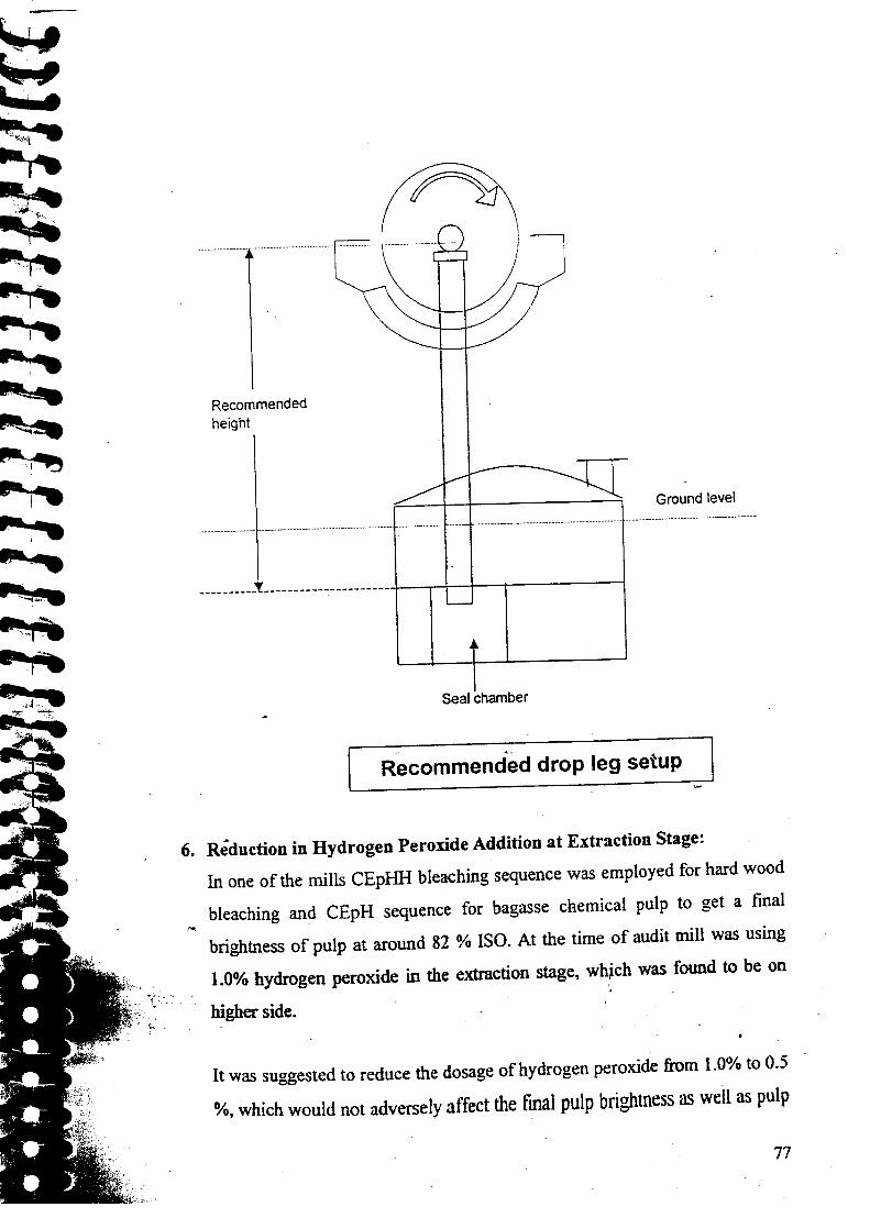
Recommendedheight
Ground leve.._.__ .._.-.-_ .._ .._--_ _-_ .._ _ _........... . _............................ .._ _ _- ..._ _ __ _ .._-._ ......•..................... _........... . _ _ __ ....•...... _ _ .
________________________________~~-+--+----------l
Seal chamber
,.;,.~
Recommended drop leg setup
6. Reduction in Hydrogen Peroxide Addition at Extraction Stage:
In one of the mills CEpHH bleaching sequence was employed for hart
bleaching and CEpH sequence for bagasse chemical pulp to get
brightness of pulp at around 82 % ISO. At the time of audit mill wa
1.0% hydrogen peroxide in the extraction stage, which was found tc
higher side.
It was suggested to reduce the dosage of hydrogen peroxide from 1.O~
%, which would not adversely affect the final pulp brightness as well
quality. Mill was suggested to conduct laboratory trials before implemen
the proposal.
.7. Adoption of Oxidative Extraction (Eo):
Use of gaseous oxygen in the extraction stage of bleaching enhances
removal of lignin present in the pulp. By adoption of oxidative extract
(Eo) in the existing CEpHH/CEpH sequence, 25-30 % reduction in ka
number can be achieved without affecting the pulp qualities, like freeru
viscosity etc. The effluent from bleaching sequences containing oxidant
the extraction stage applied on chlorinated pulp showed decrease in cc
substantially.
It was suggested to use oxygen at extraction stage to lower the kappa num1- and increase brightness of pulp. The existing CEpHH and CEpH sequence
bleaching can be converted in to CEopHH and CEopH bleaching sequer
by putting up an oxygen mixer in place of existing alkali mixer.
8. Pumping of Bleached Pulp from Pulp Mill to Stock Preparation Throu
Medium Consistency Pumps Instead of Low Consistency Pumps:
In most of the mills the bleached bagasse and hard wood pulp is stored
high-density storage tower. From this tower the pulp is pumped to sto
preparation by diluting with machine backwater. The consistency in the hig
density tower is around 8-10 % in the upper portion and 3- 4 % in the low
portion. Machine backwater is pumped from paper machine to the higl
density tower and pulp at 3- 4 % consistency is taken to the stoc
preparation. In one of the mill it was observed that the distance betwee
high-density tower (old pulp mill) and stock preparation was approximate]
lOa meters. where as the distance between HD tower (new pulp min) an.stock preparation was more than 500 meters. This requires huge ammnt (
••
7

pumping energy to transfer stock at 3 % consistency and to pump n
backwater from paper machine to HD tower.
It was suggested to utilize medium consistency pumps for transfer of!
around 8 % consistency from HD tower to the stock preparation. This
result in considerable saving in the pumping energy.
9. Replacement of Seal Tank pump in Pulp Mill:
During audit studies in pulp mill section of one mill, seal tank
discharge was measured by flow meter. The flow of the seal tank pur
recorded as 140 m3/hr. The head developed by pump was 22 mete
power consumption of 22 kW. During discussion it was informed by t
personnel that impeller was already trimmed by 10%. It was sugge
replace the existing seal tank pumps with higher efficient pump of 75
efficiency.
10.. Use of Hot Water in Place of Fresh Water at Malone Filter Insta
Blow Heat Recovery System in Pulp Mill:
During audit in one of the mills, it was observed that the hot water rec
from blow heat recovery system contains some amount of fiber becaus
was no fiber separator at the top of the blow tank. To remove this fibe
hot water, mill was using malone filter. For washing of the wire of I
filter, mill was using fresh water showers, which reduces the tempera
hot water from 84 -85 Oc to "74-75 0C. It was suggested that mill COl
hot water in place of fresh water at malone filter. Supply line of the hoi
may be taken from the. outlet of supply pump of the hot water tank.

ll. Installation of Slotted Centrifugal Screen after Brown Stock Washing
During the audit in one of the mills. it was observed that for the remova
debris contents present in the pulp, mill uses Johnson knotter screen bel
the brown stock washing which has 8 mm round hole. Sieves and small Sl
cooked chips pass through the screen, which was visible at brown suI _
washers. After washing, the pulp was diluted and passed through centisoi
with round hole screen. At the centisorter small semi-cooked chips w
separated out, but sieves still remained with pulp and were taken to
bleach plant as such, where they consumed more bleaching chemicals. fv
was suggested to either install centricleaners after centisorter or slot
centrifugal screen instead of centisorter for proper screening of pulp.
12. Utilization of Old and Redundant Equipments:
It was observed in one of the mill that it was using four stage brown sto
washing system, which has washing capacity around 160 tones/day. As 111
has increased its production up to 200 - 210 tonnes Iday, these washers we
overloaded and resulted in poor washing efficiency (soda loss - 40-45 kg/n
of pulp as Na2S04 ). It was suggested that mill should use their 0
redundant bleach line washers as brown stock washers for proper washing
unbleached pulp, 70 % of the pulp could be washed through existing brov
stock washers and rest 30 % of pulp could be washed through three of the 0
bleach line washers (as 4th washer i.e. former hypo-2 washer was of Iow
capacity)
13. Use of Chlorine Washer Filtrate for Dilution of Unbleached Pulp Befor
Suction Filter:
During the audit, it was observed in one of the mills that for the dilution c
the pulp before suction filter in the pulp mill it was using machine backwate
8(

as well as fresh water sometimes. As the residual chlorine level in the
of the chlorine washer was on higher side (0.0137 - 0.0355 gil),
recommended that mill should use chlorine washer filtrate for dilu
unbleached pulp. This will also lead to reduction of overall c
consumption in the bleach plant.
III. Chemical Recovery Section:
1. Indirect Steaming of Concentrated Black Liquor in the Mixing
Prior to Firing:
It is a prime goal of chemical recovery section of a mill to fire black Ii
highest possible concentration. In one of the study it was observed the
liquor from cascade evaporator was received in the mixing tan
concentration of 70% solids and a temperature of 87°C. Prior to firin:
boilers, this concentrated black liquor was mixed with hopper ash fr
recovery boilers and heated to a temperature of 110°C. Heat
concentrated black liquor was done by direct steaming with 30 psi ste
control offiring liquor temperature.
It was proposed to replace the direct heating system with indirect
system. Indirect steam heating of concentrated black liquor in the
tank would provide the following benefits:
• Improve recovery of condensate to power boiler.
• Save fuel.
• Save make-up water and its treatment cost.
• Improve thermal efficiency of recovery boilers.
2. Replacing the Steam Driven Ejector Sets with Vacuum Pumps
Evaporator Plant:
In one of the mills it was observed that steam ejector sets used in the multi:
effect evaporation plant consumed steam at the rate of 170 kglhr. It \~
suggested that by replacing the stearn ejector set with vacuum pump I
liquid ring type), lower operating cost could be acheved incurred. It ViI . . .
proposed that ejector set should be replaced by vacuum pump operating w
a 20 hp, high efficiency motor.
3. Thermal Treatment of Bagasse Black Liquor for Viscosity Reduction:
Bagasse black liquor has inherent problem of high viscosity at high soli
concentration. This is due to lignin-carbohydrate complexes (LCC) present
bagasse black liquor. The LCC can be easily broken down by using thenn
treatment option, where the liquor is subjected to a thermal shock
temperature higher than the pulping temperature to disrupt the lignin ar
carbohydrate linkage. In one of the mill it was suggested that mill should ~
for Thermal Treatment of bagasse black liquor, if no substantial reduction i
RAA is achieved after optimization of bagasse black liquor propertie
Thermal treatment involves heating of semi concentrated black liquor (35 t
40 % solids) to l80-1850C and maintaining the black liquor at th
temperature for about half hour. This can result in substantial reduction c
auxiliary fuel and also produce steam at higher economy from back liquoi
Low viscosity would result in Jow power consumption also.
4. Installation of External Pre Heaters in the Evaporation Plant:
The old Multiple Effect Evaporation Plant in one of the mill was ofL TI' typ:
with forced circulation and consists of 6 Effect bodies and one forcer
circulation body. Of these. 4 effects were in operation. Liquor flow sequence
was E4 - E5 - E3 - E2 - El - F.e. There were no preheaters and the Steam
82
economy was low i.e. 2.8 - 3.0. It was suggested that external f
should be incorporated in the plant before E 1, E2 and E3.
5. Efficiency Improvement of Lime Mud Filter:
During the audit in a mill, it was observed that dryness of lime sludg
on lower side i.e. only 38%. To improve the dryness & efficiency
filter, following points were suggested;
• Wire cloth must be stiff on the circumference of the drum.
• Leakages at the sealing plate at both the ends to be arrested.
• The pipe containing spray nozzlesto be shifted towards feed.
spray nozzles to be modified to spray the hot wash water prop'
• Replace 3 stages washing with single stage.
• Check the rotor of the vacuum pump for any scale build up.
6. Insulation of Bare Pipes & Vessels in Evaporator Section:
During an audit it was observed that pipelines are not properly insu
evaporators (MEE I, MEE II and MEE III) of chemical recovery secti:
surface temperature when measured by CPPRI team was found to be
as 80-1200C. This resulted' in high energy loss through these unin
surfaces in the form of radiation. It was suggested to put proper insula
the uninsulated surfaces of pipelines in evaporator section to reduce tIloss through radiation.
7. Re-use of Pump Sealing Water in Evaporator Section:
During the audit in a mill, it was observed that sealing water of 12
pumps in the evaporator section of chemical recovery was going to
The quantity estimated was around 100 m3 / day. It was suggested tI1

water should be collected in an under ground tank and recirculated witt
help of pump of required capacity.
••'8. OptimiZation of Excess Ai! in R~covery Boiler:
MOnitoring and control of recovery boiler flue gas parameters is an impor
study for energy audit. During the audit studi~ in one of the mill,' flue
analysis was made at boiler-bank outlet and ESP inlet. The 02 percentag
boiler bank outlet was 5.2% whereas at ESP inlet 02 was 9.3% & 8.0%. T
clearly indicated that there was some infiltration of air between boiler be
and ESP. Based on measurement taken by audit team, mill personnel blocl
some visible holes to. arrest the infiltration. Again the measurement of I
was taken after arresting the infiltration of air, which was found 7.5~. N(
the reading was found within controllable limit. It was recommended
control the carbon monoxide by preventing the carryover & by prop
combustion, which could be done by proper distribution of air at primm
secondary & tertiary zone and also to maintain the bed temperature
optimum level so that combustion may take place properly.
9. Condensate Recovery from Recovery Boiler:
Condensate is a valuable energy source and should not be wasted anyshen
During audit study in one of the mills it was observed that lot of condcnsat
was going to drain. Mill has provided a condensate-co.llecting tank, wher
condensate was collected from various areas, D.M. water was sprayed m th.
collecting tank and finally it was pumped to feed water tank. A lot ofvapo
was venting out from the collecting tank, resulting in huge loss of heat &
condensate and system was found to. be inefficient. Firstly it was
recommended to. relocate the condensate tank so that 100% condensate
recovery could be achieved. Further it was suggested to relocate the e>isting
84

collecting tank & erect this tank 2 feet below the existing floor. Co
the condensate from above areas in >ll common header by laying a
pipeline and to connect common header to condensate tank just 01
below the center of the tank. It was also suggested to provide 3" d
inste_adof existing 6" diameter or vent pipe to reduce the vapors cal
Mill should also provide two D.M. water shower pipes, first one just 4
below the vent pipe and second one >600mm below the vent pipe,
maximum condensate recovery could be achieved. Existing pump 1
used to deliver the hot water to feed water tank or polishing tank.
10. Installation of Heat Recovery System to Recover Waste Heat from
During the audit studies in one of the mills, it was observed that m
operating continuous blow down (CBD) system for FBC & soda re
boilers and this CBD was going to drain. It was suggested to insta
recovery system to recover waste heat from CBD by;
I. Installation of flash tank (operating at 3.5 to 4 bar) for col
the blow down water from all the 4 boilers.
ii. Flash the blow down water in flash tank to a pressure
kglcm2 and feed the flash to deaerator.
iii. Send the remaining condensate to pulp mill or mix wit
condensate of evaporator.
11. Installation of Steam Traps for Condensate Removal:
Steam traps are common device used to re.move condensate from the
line. Many mills continuously discharge the condensate without using
During audit studies in one of the mills, it was observed that turbo feed
was always in ready mode for instant stating, due to which steam was !
drained continuously from governor head, exhaust line and main chaml

Approximately 4 kg/hr of steam was gomg to drain per hour. It
suggested to install steam trap at the above locations i.e. at governor h.
exhaust line and main chamber, so that only condensate could be drai
instead of stearn. The condensate coming from the trap can be collecter
RIB cooling/collecnng water pit.
12. Replacement of Feed Liquor Pump in the Evaporator street:
During audit studies in a mill, flow of feed liquor pump of evaporator \
measured by flow meter to check the efficiency of the pump. The measur
efficiency of the operating pump was very low. Pump efficiency v
calculated on design parameters, which was only 37%. So the pump v
inefficient in both the cases. It was suggested to isolate the feed pump and
feed the liquor with the help of vacuum in the system i.e. 600 mm Hg. Due
vacuum, liquor would be sucked inside the system, since the head was 8
meters. It was suggested to utilize the pump only during startup, once t
system is stabilized the pump could be isolated. Flow control could be doi
with the help of control valve. Secondly the pump was very inefficient, and
was recommended to go for a new pump or with the help manufacture:
impeller trimming could be done up to 10% of the total diameter. It w:
suggested to study the pump characteristics curve before trimming tl
impeller. Impeller trimming could also result in energy saving but increase i
efficiency of the pump would be very marginal, since the design efficienc
itself was on lower side.
13. Optimization of Causticization by Using Good Quality Lime:
Quality of white liquor from caustisization section depends to a large exten
on quality of lime used. During audit study in one of the mill, it was observer~ .
that mill was producing 60 m-t/hr Green Liquor of 75 gpl. The Green Liquoi
86

was treated with lime having 48% - 50% Available Lime Index (ALI)
resulted in White Liquorproduction of only 60 gpl concentration.
In the slacker, mill was using live steam of 0.5 kglcm2 pressui
temperature 135-1400C for raising reaction temperature from 70 to 8(
was suggested to use good quality lime of 60% Available Lime Index
By using high purity lime mill would be benefited by raisin
concentration of white liquor from 60 gpl to 100 gpl also no steam wo
required for slacking.
14. Insulation of Bare Pipes & Tank in Chemical Recovery Section:
During the audit studies in one of the mills, it was observed that in ch:
recovery section some pipelines and tanks were not properly insulate
surface temperature when measured by audit team was found to be hi!
ranging between 80 - 160 0c. This resulted in high-energy losses tt
these uninsulated surfaces in the form of radiation. It was suggested 1
proper insulation on the uninsu1ated surfaces of pipelines and
in chemical recovery section to reduce the heat losses th:
radiation.
15. Increasing the Temperature of the Flue Gas in Boiler to Increai
Service Life of the ESP:
In one of the mills, semi concentrated black liquor (SCBL) at a concent
of 45% IDS from the evaporators was further concentrated in theJ
contact cascade evaporator using the flue gases from the recovery boil
was observed that the flue gas temperature after the cascade 1 & 2 un
the MHI boiler, was only 110° and 1190 C respectively. It was suggeste
the exit gas temperature from the cascade evaporation must be maim
above the dew point of S02 i.e. above 1490 C. The flue gas temperature could
be increased by reducing the energy demand of the cascade evaporators by
raising the MEE outlet concentration from 45% TDS to 50% TDS. It was
proposed that by retrofitting a 3-section plate type concentrator prior to the
. existing effects, the outlet concentration of FF rviEE could be raised. Higher
product liquor concentration could be achieved in the LTV design evaporator
by incorporating two additional falling film effects after the forced
concentrator body.
16. Replacing the Steam Driven Ejector Sets with Vacuum Pumps in Multiple
Effect Evaporator:~eam ejector sets were used in the rviEE for evolution of non-condensible
gases from the evaporation plant in one of the mills audited. It was suggested
that the lower operating costs could be incurred by replacing the steam
ejector sets with vacuum pumps.
17. Installation of Secondary Surface Condenser and Stripping Column to
Purify the Foul or Contaminated Condensate Generated from the
Evaporation Plant:In one of the mills, the secondary condensate at the rate of 230 m
31hr. was
generated from falling film & LTV Evaporators. This secondary condensate
reportedly has black liquor entrainment. As a result of which, only 100-
m3/hr condensate is being utilized in the recausticization plant while the
remaining condensate i.e. about 130 m3/hr at 60° C was diverted to the E.T.P.
It was suggested that the mill should install a stripping column to purify the
foul condensate in order to facilitate the condensate return to power boiler. It
was also suggested that a secondary condenser should be installed in series
with existing surface condenser. The primary and secondary condenser
should be so designed that the primary unit condenses approximately 85% of
88
the vapor which contains only small amount of odorous & BOD pre
compounds. The secondary unit condenses the remaining 15% of tht
containing major quantities of these objectionable compounds
arrangement permits separation & concentration of foul condensates
tum would reduce the condensate stripping steam requirement.
IV. Stock Preparation and Paper Machine Section:
1. Use of Ferric Alum in Place of Non-Ferric Alum in Unbleache
Coloured Varieties of Papers:
The paper mills in India produce multiple varieties of paper. In one
study it was observed that the mill apart from producing bleached ~
was also producing unbleached board and coloured varieties. Out of th
paper production of 77,974 tons per annum, the unbleached and co
varieties account for 27,609 tons of paper per annum, which was abou
of total production. For sizing the paper, the mill was using fortified
size and non - ferric alumlgum rosin at the rate of 1.2 - 1.5% and 7 1
respectively. The non-ferric alum was received in solid form by the n
was recommended to discontinue the use of non-ferric alum in unble
and coloured verities. Non -ferric alum is generally used in bleached B
where brightness is an important parameter. Since brightness is m
important parameter in case of unbleached and colored varieties a I
cheap alternative of use of ferric - alum was suggested.
2. Replacing the Exhaust Fan in Paper Machines Hood:
In one of the mills, the dryer part of MF-I & MF-2 paper machinesI
partly covered with hoods. The hood has ducts fitted with exhaust f
draw the moisture laden air from inside the hood to atmosphere resu
from the evaporation from dryer surface on backside. On careful examim

of duct, it was observed that design of exhaust fan in duct was not correct
case of PM 1. the exhaust fan was attached to the shaft.
It was suggested that the design of existing exhaust fans should be chang.
The electric motor, which was placed outside, should be removed a
circular hole should be closed-
3. Insulation of Steam and Condensate Pipelines in Paper Machines:
During the visit the mills, it was observed that maximum number of steal
flash steam and condensate Pipe lines coming in the dryer section of pap
machine were not insulated. The surface temperature of these pipelines w
as high as 110° C to 1500 C. This indicated the high-energy loss in the for
of radiation. This situation should be avoided because it results not only :
energy losses but also increases the ambient temperature of working plac
causing problem for the persons working there.
It was recommended to put the proper insulation (asbestos rope type) emth
bare pipes to reduce the heat losses through radiation and to save the energy.
4. Installation of' On -Line Streaming Current Titrator for Wet ED<
Charge Measurement:
In one of the mills, it was found that paper machines were not equipped witt
anyon-line wet end charge-measuring instrument. Now- a-days, most Gf the:
high-speed machines are going for on line wet end charge measurenents.
This is necessary to manage the complex wet end chemistry more
scientifically and with increasing flexibility. To-date, manufacturers have
installed on line streaming current titrator on numerous paper and roard
machines throughout the world. These installations have shown that
stabilization of wet end chemistry and control of the system cationic deaand
90
and charge is the base for all benefits possible from the technolo
instrument provides an easy-to-use simple and practical appro.
monitoring and control of paper machine wet end.
5. Installation of On-Line Wire and Felt Cleaning System on
Machines;
During the visit to the mills, it was found that paper machines wire (
cleaning practice existing in mills was of conventional type i.e. the IT
was shut for cleaning the wire and felts. It was suggested to install~ ~~
wire & felt cleaning system on paper machines to reduce the downtii
to cleaning of wire and felts. Various on-line cleaning systems are av
and details can be taken from the suppliers in this regard.
6. Insulation of Sides of Dryers and M. G. of Paper Machines:
The sides of the drying cylinders and M.G. dryers are generally not ins
which results in losses through these open sides in the form of radiatio
loss of heat from dryers sides resulted in lower drying capacity, more I
consumption or low speed of machine leading to production loss. Duri
audit studies, the CPPRl audit team suggested to insulate the sides
drying cylinders/ M.G. of paper machines to reduce the heat losses thradiation.
7. Proper Utilization of Cooling Tower in Paper Machines:
Cooling towers installed in most. of the mills were found to be under ut
~.During one of the study it was observed that 80% of total water being w
the cooling water (20m31hr) was being recirculated through overflow ta
cooling tower. It was also observed that the cooling tower fan wa
running and as a result the temperature difference found was marginal
close study revealed that fines coming with backwater blocked the co
tower fins resulting in efficiency losses. It was recommended that the on
filters should be installed to separate the fines coming from macl
backwater. The cooling tower fan should be repaired and started to get .
efficiency of cooling tower (In winter season the fan was suggested tc
stopped). Suggestions were given to utilize 100% water in all the vacr
pumps and o~er pumps in paper machines for avoiding use of fresh water
8. Use of Machine Back Water in Place of Fresh Water in Paper Machin
Paper machine is the area where maximum recycling of machine backw:
takes place. In one of the mill it was observed that fresh water is being u
at couch pit, thickner and Johnson screen in five paper machines. It \
recommended that at these points, machine back water should be used wh
would not affect the paper quality.
9. Recovery of Condensate from Paper Machines:
Condensate is a valuable energy source and should not be wasted anywhere. Duri
audit study in one of the mill it was observed that condensate in one of the pal
machine was going to drain. The volume measured by audit team ~
approximately 60 LPM at temperature of 900C. It was recommended that t
condensate of paper machine be pumped to power boiler / D. M. Plant for its hi
utilization.
10. Replacement of Defective Steam Trap at Paper Machines:
Steam traps are provided in the steam pipelines to remove pipelir
condensate without steam losses. However the leakage in traps results
major steam losses. During the studies made in plants, special attention We
paid to trap monitoring and in most of the cases along with quantitativ
analysis of losses, it was observed that steam traps fitted at the steam lin
were not working properly. Suggestions were given to follow a reguls
9

maintenance schedule for steam traps. In one case it was observec
trap by-pass valve was kept open, and as a result the steam was bein:
at the rate of 20 kglhr. it was suggested to replace the existing st,
with new efficient steam trap.
U. Installation of VFD in Back Water Jump at Paper .Machines:
Variable frequency drives (VFD's) provide significant energy sav
regulating the motor speed and there by the flow from the pumps. ~
significant energy saving measure in cases where pumps are operatir
capacity and the valves are throttled to regulate. the water flow. Du
audit study in one of the mills, it was observed that the backwater pu
running only with 25% valve opening. The matter was discussed w
officials and they informed that the valve was adjusted accon
grammage of paper and it varied from 120 m3lhr to 250 m31hr. DUl
25% valve opening the flow was 120 m3/h and at this operating condi
efficiency of pump work out to 17.8%. Accordingly the pump efl
would be 20% at 250 m31hr. flow for actual developed head of lOme
was proposed to replace the existing pump with new pump of high eff
(75%- 80%) and to regulate the flow with VFD, to control the flow pras per the requirement.
12. Cascading the Steam & Condensate System Arrangement in 1
Cylinders of Paper Machines:
Condensate is expensive with regards to its heat content and the
purification cost, therefore its wastage is considered as significant lo~I
efforts should be made to recover the flash steam from condens-. ,,
processes wherever indirect heating/ drying takes place. Paper me
condensate is flashed in condensate tank and the flash steam is availal

utilization. The available flash steam can be utilized by cascading
condensates flash steam in first group dryers. During the audit in one o:
mill it was noticed, that the condensate generated from dryers, collecte
condensate tank and pumped to Boiler House and the flash steam fromi
condensate was not utilized. It was proposed to flash the condensate in f
tank and use the flash steam in other groups of dryers using cascade syster
13. Removal of Backwater Pump at Paper Machines:
During an audit, it was observed that backwater generated from machine 1
6 was collected in an intermediate tank and then pumped to backws
storage tank at ground floor through a pump connected with 15 kW mo
which was consuming 12 kW power. Detailed study revealed that pump ~
not required and could be by passed by laying straight pipe to backwa
tank; as the water can flow through gravity. Therefore it was recommend
that the back water collected in the side tank at back side of paper machi:
can go easily to backwater storage tank at ground level by gravity and the
is no need to pump the backwater from first floor to ground floor.
14. Increase the Capacity of Primary Centricleaner Reject Tank Installed ~Paper Machines:
During one of the studies, it was observed that centricleaners in the approac
flow of paper machine were not functioning properly. The machine has tw,
stage centricleaners. The reject of primary was passed through secondarj
stage and reject of secondary was going to drain. It was observed that the
overflow of primary centricleaners mixing directly with the secondary rejeci
was going to drain. This was due to low capacity of primary reject pit. It was
recommended that primary centricleaner reject overflow to secondary reject
should be stopped, by increasing the primary reject tank capacity.
94

15. Use of Paper Machine Backwater In Place of Fresh 'Vater at Co
of Paper Machines:
In one of the mills, fresh water was found to be used in the knocl
shower of couch pit for removing the paper web from the wire, Fresl
was also used for dilution of pulp before pumping it to the chest. The
was running most of time with an average flow rate of water ab
liter/min. Use of paper machine back water was suggested in place c
water for the dilution of pulp at couch pit.
16. Installation of Deckle Strip on the Sides of Wire Table near
Opening of Paper Machines:
The studies in one of the mills, it was found that stock from the he
slice, spread all around the machine edges near breast roll, which resu
the spillage of stock on floor and machine moving parts like table rc
This being direct loss of pulp and other additives, also spoiled the shoj
area resulting in bad house keeping. Deckle strip was suggeste
installation on both sides of all 6 machines in the mill.
17. Reusing of Cooling Water of Hydraulic Loading Unit of Refill
Paper Machine:
During audit study in one of the mills, it was noticed that about 80
cooling water from hydrodynamic loading system of refmer at PM _
going to drain. It was suggested to reuse this water in system itseconnecting the outlet pipe to incoming line.
18. Installation of Horizontal Agitator at Couch Pit of Paper Machines:
It was noticed that the couch pits of 6 paper machines were found not
equipped with any agitator. During the time of break. paper web collect
couch pit was pumped to chest for mixing with machine stock. The I

web was diluted with fresh water. Due to lack of proper mixing of paper ,
water, the stock could not get homogenized and resulted in unnecessary I
on the pump. Also the stock received at chest was, not found to be unifi. I _ - ~"""...'...,..•..'-. ~....,..<i...... " 4"". •
which ultimately disturbs the chest consistency, and .r~Hltc:d' ingramm"'J"', 'j"'l'''1'111 "'fU.U e',JQ li •. ~ ,',- ·-.rt"~ 1:.1',1 f .•.t';:~\":"':;~J ~_-r! tJ', .~.HIUf).l.-_,;-~,"·i,."; ~''';_ Ju.;'•...,.__~-._t.."'.t" "', "
HWI_ld ,'·:Jf~vanaiimi·of~aper: It'\vas proposed that mill should install'proper agitator:, .. . ·· ••q"·"ff7l·<k'rlff' ~. "".,.~~:"oFq:~~!tnivotn!J1'1Ql;;1(J' t!~urolu 1~W'I(Jn.t..
":if.N rl2!'hori'kntaI tyJ,giitilie'coticn pits. This would result in proper mixing of srI . .
and produce homogeneous stock as well as result in low load on pump. 1
would also reduce grammage variation and improve the paper quality.
19. Proper Cleaning /Thickenlng at Hill Screen of Stock Preparation PlaD1
During the visit to one of the mills, it was observed that hill screen instal]
at stock preparation plant was not functioning properly. The inlet distributi
pipe of hill screen was damaged from many places resulting in heavy sto
flow from pipe. The most of the nozzles of pipe were also jammed. Most
the stock was going down the chest without any dewatering because
insufficient retention time to stock. It was proposed that inlet distributii
stock pipe should be changed/repaired so that stock should flow across tl
full width of hill screen with enough retention time on screen and resultproper dewatering.
20. Installation of Enclosed Hood at Dryer Sections on Paper Machines:
In India many mills are using second hand paper machines and the machine
are not equipped with enclosed hood. In one of the mills, it was found the
the dryer section of 6 Nos. paper machines do not have any hood. Onl
machine No.5 has open canopy over top of dryers, which was also nc
functioning properly. In absence .of the hood in paper machine dryer
moisture evaporated from the paper surface can not be removed efflcientlj
from machine house, which results in dripping problem especially in the
rainy and winter season. It was recommended to place enclosed hoods on the
96
dryer section of paper machines. It should consist of an insulated
above the operating floor. Front lifting panels and rear-sliding p
used to provide access to the dryer above the operating floor.
V. Electrical and UtilitiSection:
1. Preheating the Combustion Air to 150°C in the Boiler:
In one of the mills, combustion air temperature in boiler was fou:
maintained lower than the designed values. it was proposed that in
attain better combustion efficiency, the combustion air must be preh
2. Replacement of Oversizedl Under Loaded Motors with SmalMotors:
During the audit studies measurements were taken wherever poss
ascertain loading of major LT induction motors in the plant w
objective of analyzing this data for identifying underloaded motors.
pointed out that the operating efficiency and power factor of unde
motors is lower resulting in wastage of energy. The motors, which a
than 6Q% loaded, are considered to be underloaded as there is more SCI
saving through replacemem or reshuffling of these motors. Suggestion
given to the mills for replacement of these motors considering the ~
application that the motor had been put to, before trying to replace i
smaller motor of optimum rating. In this regard,high starting 1
.',' l' 't:lJ.~·;j . 0-y~U~,~~~;~t,~v~\\'~~t!~'l1if~';'~;~~~~:~?oo.::mcreaserequrremen ,. dJiiture plans forcapacl~,hikezmOdificatiollS·~#,~"\'J;;~~'1llfeS~~~"f.~~
- mOnitoring of underloaded motors, specific case-to-case deciSion wereto replace them with smaller motors.
3. Optimization of Fuel Combustion in Boilers:
Energy audit team conducted measurements of excess air by using portal
flue gas analyzer, In one of the mill the oxygen level in flue gases van
from 8.0 - 9.0/ % in boilerNo. 6 and 5.5 ~ 9.0 % in boiler No.7. 'The hi
.oiYg~4fiJ{,~f~fl~eW~~~oPt2df~t~dt~'~~~r-OJfrddnria~'rtd~'bu~ti~ilP'T~m~2rili1~Ji'63l ~!6~i'%i~b~ileiN~'"6 ~d '47~r6l8'%~'b~ii~~!No~'7. T
high amountof excess air takes away large amount of usable heat with it aJ
results in higher losses through flue gas exit. Audit team suggested prop
balance of ID and FD fans to maintain the oxygen level in flue gas betwec
5.0 - 5.5 % by proper damper opening or by installation ofVFD.
4. Maintain Uniform Ratio of Mixed Fuel in Boilers:
Mills use mixed fuel like imported coal, raw lignite, pith, coconut shell an
wood dust in Boiler No.6 and 7 in different ratio. The variation was found i
fuel feed rate and ratio for 6 days of the study period. It was suggested the
the wide variation in fuel mix resulted in significant variation of calorifi
value and moisture in the fuel. As a result boiler-operating conditions wer
disturbed very frequently. This ultimately lead to variation in performance 0
boiler efficiency. The calculation conducted with operating paramete
indicated that with in a period of 6 days, there was a variation of 1 - 2% ir
boiler performance efficiency only due to variation in fuel mix. The
moisture variation with feed variation disturbs the operation and efficiency olESP's also.
5. Reuse of Caustic Used in Regeneration in Strong Based Anions Cell of
D.M~Plant:
During the visit to one of the mills, it ~as noticed that 200 kg (solid basis) of
caustic soda was being used for regeneration in strong base anion cell ofDM. ,
Plant twice a day. Prior to feeding into the resin column, caustic was
98

dissolved in water to make a solution of 60-70 gpl. The caustic sup]
regeneration was not used completely and about 35-40 % of caustic
unused and was going to the drain. Out of two charges in strong bas
cell one wash was used to charge weak base anion and wash of
charge was going to drain. It was suggested that wash of another
presently which was going to drain should be collected in a tank and
use for caustic dilution / chemical recovery / pulp mill.
6. Installation of Isolation Valve at D. M. Plant Vessels:
In one of the mills, it was observed that anion / cation / mixed bed,
vent lines were kept open continuously after venting the air, which ws
mainly for easy operation of the plant and also there was no isolation
On an average approximately 180 LPM of water was going to
continuously. It was recommended to provide isolation valve for the
vent pipe, so that valve can be opened and closed after venting the vess
7. Installation of Permanent Pipeline with Shut Off Valve in Samplin:at D. M. Plant:
During the audit study in one of the mills, it was observed, that samplir
of polished water of ammonia dozing was continuously kept open an
polished water was going to drain through a hosepipe. Almost 20
polished water (1.2 m3 I hr) was going to' <hin through hosepipe. 11
recommended that a permanent pipeline with a shut off valve
be installed in- place of hosepipe from-the main line and the sample s: . ~.'" ""# ~ ;'_i>'.'~$., '" .•. ;t, ~.'i:"",', ,~.,.:) ,':-"'.... .' ~~ .c.
'~~'1ii~~~~;~~:~=~~~~,~tld/g~~'~;Qi'~"~;'I<" t,'''}t,.i<.~ ':-"W" 1'I~•.";"i •••t~""'t::';"""':';:"'~;rl'; ,i,;"" __ I'·t.h,,,,, j," 'l., 'i""""'I'llp-""t.,.••••.• 'H.l,~ t'" ,.b:.t1lJ;;"-r....l",,,...,.;. •.,,¥f~;'W" ~", ,~",,~,-~1..;" l;'~"r...',{", .~,t,,J.. ',_
Bypassing 0(-Intermedia'te Screw Conveyor in Power Boiler:'- i
In one 'of the m,iIls,it was observed that mill was using 3 nos. of ~
Conveyor to discharge the ESP ash. It was proposed to by

intermediate screw conveyor by extending the lSI conveyor by abo
.2 meters.
, . - - I .. ,'. "-, ...~ ....,'".'., .....-9. . Optimization of FreshWater Consumption in Mill: . . .
:)riJo~,t)Duringthe~ aJdit:r~itrd~f~~bri~;()f~ili~< ihiUs;u if wasri~~~eivid'fill~t.in ea. .' C<:, """.1 t!>' 1:,•••.~:.:~ru','J.,~w,.t g.Q.(>~:'.LlUH •..•h~U. c."t..-i"..~g il.U!.,!llnnt-!, \,:{JlnOI 1:-111';, .
. ,,: - section: the fresh water taping of size' 1" & 2" were provided for gener, .
purpose. These fresh water taps were noticed continuously kept open durir
audit studies as a result approximately 600 LPM fresh water was going ,
drain. It :was proposed to provide 114" or maximym 1/2" taping i
place of existing 1"I 2" size of fresh water and also to provid
plunger type valve to avoid wastage of fresh water.
10. Provide Local Electrical Switches in place of Common Switches:
It was observed that for general lightning purpose common switches wer
provided in many places i.e. mainly in Recovery Boiler & Finishing Hous
Sections in one of the mills. Therefore all lights were in on condition i
daytime because light was needed at a particular place. It was suggested t
provide local electrical switches in place of common switches to avon
lighting during daytime wherever it was not needed.
11. Motor Efficiency Testing & Saving Potential by Replacing with Energj
Efficient Motors:
In one of the mills, some selected motors were tested under load condition:
as per IEEE specifications. The motors, which were running below the
required efficiency level, were suggested to replaced by energy
efficient motors.
100

VI. Others:
1. Collection of Over-Flow Water from High Pressure Cleaning]
Evaporator & Pulp Mill Section:
The overflow water of service tank provided with high-pressure mad
going to drain (Approximately 7.2 m3/hr) in one of the mills, wher
were conducted. It is suggested to provide a service tank of MS/(
with high pressure pumps of capacity about 3-5 m3 with control valv
use the overflow water which was going to drain.
2. Replacement of V-BeIt by Flat Belt of Vacuum Pumps, Agitators:
Blowers:
During the audit in many mills, it was observed that multi grooves'" ~
drives were in operation to run the vacuum pump and agitators. FI
being much more flexible than the V-belts and also requires less em
traveling around the pulleys, friction losses are less compared to V-be
belt is free on the pulley since there is no wedging into the grooves a
over all energy saving occurs. It was suggested that vacuum pum
agitators should have flat belt type drive systems.
3. To By-pass the Mechanical Bar- Screen at E. T. Plant:
During audit studies in one of the mills, it was observed that mechani
screen installed in the main drain which was going to primary elar
ETP was not properly designed. The big size particles were going bad
drain instead of removing. Mechanical bar screens were installer
': ;~con~entioriaI(bar'·scieen:}and tlie)8ig~WCfes~iihttJ~~aYtgdr~3=;~;:~1~~i~\·i~~~~~,.~:~~l"f;~~,{:·~J!1:~I~I;:··~i'(2~~,!zy.:Z}~;;~'+l·~·~{R:"0 ,i: ~. . '; ~;;.,~.,}~,r
these screenS."OnIy few particles were 'gomg'to mechanical bar sen
nos.), which were running with the help of 2 motors of 2 lIP each.
proposed that either mechanical bar' screen should be properly desigi

remove all foreign material or stop them. One person may remove t
~9~:~;;.;J;;;~jl1;~mnt~~~~~~:,; ..·:;~,·;:tY'i'ti.{;~.(\{~f;~;}~~r.j· ·~.:;hrtt1N;{~:';"'Y?C;.·~~.tt~~i.4,1.~'~...,.u. ,:l~~~l\r4~t~:~~.iS'.to;i't .'·}<~'~:~~~:7<?~..th.~.~lIs.~·~~\'!~\-o,~~~~~~~t~~~· ~~:~~g~,Y~~,,"~d DAJ
n~tri~~ts forbact~ria ~~the aeration tank at effluent treatment plant. Al
850 kg urea and 300 kg DAP were being used every day. It was propcI
I
that mill should use Single Super Phosphate in place of DAP. To main
the same dosing 'of nitrogen and phosphorous, mill has to increase
quantity of urea to 971 kg per day from 850 kg per day, But the quantitj
Single Supper Phosphate would be required only 225 kg/ day in place
DAP (300 kg/day).
10
AGRO BASED PULP AND PAPER MILLS:
.L Raw Material Preparation and Handling:
. 1. Washing of Bagasse Before Feeding to Digester:
The bagasse contains large amount of free sugars, water soluble com]
etc. During storage, these sugars convert in to alcohols, acetic acid
acid etc., which ultimately consume some amount of cooking chem
one of the mills the depithed bagasse was going directly to the digesi
cooking. In case bagasse is processed through existing hydr~ pulper
washing system, it can remove a portion of the pith and large portion
fine dirt, sugars and acids. It was suggested that the mill should 1
existing hydra pulper drainer washing system normally used for
washing to wash the depithed bagasse depending upon the availability
washing system. Mill can save up to 2.0 % of cooking chemical to p
same kappa pulp with improvement in unbleached pulp yield by 3.0
bleached pulp yield by 2.0 %.
2. Connect Raw Material Washing System with Continuous DI- .
through Belt Conveyor:
In one of the mills, wheat straw coming out of hydra pulper drainer w
system has temperature around 45 .; 51°C. The washed rheat straw w
dumped on ground and then sent to continuous digester throug
conveyor. In this process the temperature of wheat straw came down 1
. 35.oC in summer, in;winte'r;seas~n\thete'mper~ture~'ay\comedown 1} .~,,.4"~ _.·'·~-':,·f\, ;.,,:,:.-,.,e '~'7-""}',,:",f)'?~'::f-_ ':-~~ _"'~ _~_,_, ·,t' --, ,", " . ~'r:'__t
..~~··~o "'-r'''"!]? h;~ff/{fi~ 'J~;J.j ~·!'.v.~1m fHnL j ••~{i,!··)f~J'1o.";'~'.'-e:';;- > ·.·.·20"""C._By.connecting •.thewashing .•~ystelllrt1?l',.cP~dig~:·...... . "'. -'" ,·.iJ~.N"'"'"'''.'''".-~·'f·~.' ""',,"r.." rJ-...:I'.ii , "" ,., ,,'.~' .•• ;MI't"'.. , ,.. ,,., ,;:",f'rr ~(v~~("~-ltmh'f"1")~n!'fnsW;'ruu'~".Qlv:' . .'~JJ)'III\I""t''''-
, . conveyor belt, 'the temperature of washed wheat s~w could be man-.. '. ./'. ,.,..
on relatively higher side, before feeding to continuous digester. It woul
huge amount of steam used to increase the raw material temperatun
25°C to 45 °C:' It was suggested that a covered conveyor belt system sh
be installed between hydra puJper drainer. washing. system to the exi:
conveyor .io~r!continuous digester for transferring· the hot ~heat s':$lHiW.:i»it lJd~;1l\ii,H. tr..i.l!1l'l ibJ'l;'it .•l?i hQJ: - - .l"
- £ji~f.~8[~~f~'~~'~~W¥¥;~~~~~~i.!P.~£2~~,?-~gi~~t~~±th!S'~~1.~pre\.'entr'the'.heai'josses:·occuning in dumping and .!fansportation of w
'-< ~ ••• j\;''''.t.>---_t!~~. '~I~'Ito·.\.'''~n'4)".1''·n·~''· '"'1.1 ~--.", ,~. ,..";;-t:;~'f!r.! ).' : '\., , ., '.- " -...straw.
3. Proper Stacking of Bagasse and Wheat Straw:
During the' visit to one of the mills, it was noticed that bagasse and wl
straw was not stacked properly and raw material was falling down in the s
drains, thus chocking the drain lines. It also deteriorates the raw mate:
quality, which ultimately affect the fmal product i.e. paper. It was sugges
that mill should stack bagasse and wheat straw properly. The proper stacki
of bagasse / wheat straw would help in conservation of raw material.
4. Covering of Bagasse and Wheat Straw Conveyor Belts:
In one of the mills, it was observed that the conveyor belts conveyn
bagasse and wheat straw to depither and then to digester were not coven
resulted in poor house keeping and loss of raw material due to removal c
raw material during strong wind or on rainy days. It was suggested that mi
should cover all the conveyor belts from the top to reduce the loss elfra-
material in rainy season. It would also save the faIling of wet raw mneris
during rains on the moving part of conveyor belt, thus reducing thmaintenance cost.
5. Use of Fresh Wheat Straw in Place of Stored Wheat Straw as Furnisb:
It was observed that a mill was using about 42% of wheat straw as .I raw
material in. its furnish with an annual consumption of 12000tlannum. Mill
stored a good amount of wheat straw for its use during off seasons. Mill was
104

usmg the stored wheat straw first and fresh straw was stored
suggested that mill should use the fresh wheat straw directly and
rest incoming wheat straw to save the transportation cost incurred d
handling of raw material inside the mill.
6. Installation of Drum Cleaner for the Cleaning of Wheat Straw:
One of the mills using wheat straw and bagasse as a main raw mat
not have any system for cleaning of wheat straw. Both bagasse an
straw were mixed at the beginning of the conveyor belt and fed to (
The depithed bagasse and wheat straw were then fed to digester. The
of wheat straw without cleaning resulted in the entry of lot of dirt,
shives and unwanted material in the system ..increasing the load on c
equipment on one side and deteriorating the paper quality on other
was suggested that mill should install a drum type cleaning system t
the wheat straw from any shives, dirt, grains, particles, stone etc.
-- (---,.-.I,I, 2.5 1.0
.-.I I

7. Installation of Feed Controller at Baggase Conveyor:
During the visit to one of the mills, it was observed that the raw mate
(loose bagasse) was being put on conveyor belt manually, which was feI '.• . . . . I· .' . ... "','
:••.•H."j.·.,.~.~...n..·.....p.....t..•.H'J~.5~,·f~~~~d.'~f.•~...,:~~ .•~'ffh".'.&J~~pua~.~~eo.'~e.e.,§g"i~~~' ~.~~f~.C.9..~.tr....<?!l_e.d..by. ", " or~:.n·lJ'."'~!'.' ):rn' ·qHt"EIl\V ~·~t~·r.:.'fr .,"~'''''''"-:''';!l(!''~'~,•.."''''''to.' ."li .
~~~iS:~rf.'.~1:~~.:,~~!j,e~~".:.c.:~~,;,;.,~,;.~~f~e...\~.\"~~~~~.Lll~tWtt{ji.l!i~~ .•..~~~~lJ.lgt....u.~fu~!!i,.1.~O,', "'~~.!"t'", ;!~f'rt(('<:'''ici'~'"'''''i'' "'I .-f'·'1·"v-,·., "'., "''''''_''''''", .,' motor; there ore the operator' deputed' 'at depither" had to' stop thewtI '
bagasse feed conveyor. It was suggested that a feed controller should
installed for constant feeding to depither. The feed controller may,
fabricated locally as per the requirement.
I Tapered Plates I
Bagasse
8. Raw Material Yard Flooring with ConcretelBricks:
It was observed during visit to one mill that raw material (Bagasse) procure
from near by sugar mills was stored in open area (Approximately 10
stacks). Only 50 stacks have flooring with Concrete/bricks, rest stack do nc
have proper flooring resulted in the deterioration of raw material in the 2 or
bottom layers of bagasse bales as the material is stored for 8 months. It wa
suggested that raw material yard should be floored with concretelbricks alon,
with proper drainage system.
] O~

9. Installation of Side Guard on Wastepaper Conveyor:
It was observed in one of the mills, that the side guard was not provi:
waste paperlKCB conveyor system resulting in poor housekeepir
wastage of raw material due to falling of waste paper from sides.
suggested that side guard should be installed at waste paper conveyor.
n. Pulp Mill Section;
1. Increase the Bath Ratio in the Continuous Digester:'
Generally continuous digesters are known to produce uniform pulp, h
during the audit in one of the mill the Permanganate number of unbl
pulp produced from continuous digester varied from 12-19 (in te
kappa number, the variation is :::::18-30). It was suggested that the ba
should be increased from 1:2 to 1:3.5 for proper liquor penetrati
digestion. The desired bath ratio can be attained by addition of appi
quantity of weak black liquor.
2. Re-cooking of the Rejects of Vibrating Screen:
It was observed in one of mills, that mill. ~as screening their pulp b
Vibratory screen, Centrifugal screen and centricleaners. the rejects
out from these cleaning equipments were estimated as given below:
Vibratory screen rejects (0.5 tonnes/ day)
Centrifugal screen rejects (2.0 tonnes/day)
TCC rejects (2.0 tonneS/day)
Thus approximately 4.5-tonneslday roughly equivalent to 7.0 % of 1I
G~).pulp Produced .•:v.vasbeing10st~;,'i\por,tionpf~tllis,.C9Uld~be._r.edu~~d..~~"'11\'O:\'~'i""'C~-.'•..k.~.''lii'!li..·''ifll\\i••:,;,.at.. :...•.~ 'Ii,,,,..~.. '~.' '~'.. . ~..•.' "~_.' ..'.' ~ ~ •..'.' ~ '.'!"~:'i..~..·'.•.....•.•....~'.i r•.·l.i~a.··'.·.·_.,,"''" ,;"_" .• ,•."._"~?,~!_~,•.t",·>_,,,cd ..l',\,,.:£t}.f~~~~~~~. ",,~;~;~-.r: ~~"'."~a;~, .'~~
., .. -:'cooking :of<:vibraforY;lsCreen:tejects;;pres:eritlYnm~1f}Y~j u.Sll.lga~e, . . I
with. 14 nun diameter holes in vibratory screen of unbleached pulp. - 'I .
suggested to. reduce the' screen diameter of plate from 14 mm to 8·
This would result in reduction of centrifugal screen rejects and
centricleaner rejects. By reducing the screen diameter of plate from 14 mr
8-10 m~. the major portion of uncooked raw material/pulp can be retai
on vibratory screen, and can be re-cooked with the raw materia1.
3. Utilization of Flash Steam of Blow Tank for Heating Water:
In one of the 'mills, the wheat straw pulp from continuous digester blo
along with the weak black liquor was collected in the blowtank. 'l
bagasse/sarkanda pulp from batch digesters was also blown to blow ta
The flash steam from blow tank was vented into atmosphere without bl.
heat recovery. It was suggested that the existing heat exchanger may
utilized to heat the water by utilizing the flesh steam generated in the bh
tank. This hot water can be used at the washers of bleach plant or in f
washing of paper machine.
4. Insulation of Rotary Digesters, Blow Tank, Steam Pipelines, Hot Bla
Liquor and Pulp Lines in Pulp Mill:
During the audit in one of the mills, it was observed that mill has 10 rota
spherical digesters and some of them were found to have improper insulatio
Similarly insulation was not provided at blow tank, blowpipe lines, pu
pipelines up to washers and hot black liquor lines, and these resulted
considerable heat losses.
It was observed that in most of the cases that the insulation in digester hom
does not stand longer due to handling of corrosive materials. It was suggeste
to plan a preventive maintenance schedule for insulation in pulp mill to avoi
the heat losses. A monthly check up of insulation in pulp mill and correctiv
measures taken up immediately would yield significant savings to the mills.
101
5. Installation of Barometric Leg on Brown StockWasher No. -1& 2
Alkali Washer:
The mill audited has 4- stage brown stock washing system and at B~
1, BSW No.2 and at alkali washer, vacuum pumps were used.
It was suggested that the mill should use barometric legs for displacer
liquor in l " & 2nd stages of pulp washing and at alkali washer. In th
mill can reduce its electrical consumption by replacing existing \
pumps with barometric legs.
6. Adoption of Oxidative Extraction (Eo):
Use of gaseous oxygen in the extraction stage of bleaching enham
removal of lignin present in the pulp. In one of the mills, it was observ
by adoption of oxidative extraction (Eo) in the existing CEHH sequen
30% more Kappa-number can be reduced without affecting tlu
qualities, like freeness, viscosity etc. The effluent from bleaching se
containing oxidant in the extraction stage applied on chlorinated pulp
27-70% decrease in colour. It is possible to lower kappa number of pt
increase brightness by using oxygen at extraction stage. The existing
sequence of bleaching can be converted in to CEoHH bleaching seque
putting up an oxygen mixer in place of existing alkali mixer.

NaOH
Steam
y
Effluent mixer
Oxygen
EoTower
7. Modification in the Design of Spherical Rotary Digester for Compl
Blow Down of Cooked Pulp:
During the audit in one of the mills, it was noticed that the mill was usi
spherical rotary digesters for cooking the raw material and the pulp was I
completely blown down in blow tank after cooking. Some amount of cook
pulp always left in the digester. This left over was blown down on the fie
and was cooled down and after dilution by paper machine backwater pr
was pumped to the chest. The above procedure indicates that the design
the spherical rotary digester was not proper. There should be no pulp left
the digester after blowing. The practice of dumping the pulp on the floor at
diluting it with machine backwater resulted in excessive heat loss that cou
be otherwise recovered in blow tank. Beside this it also accounted f
increasing pumping cost incurred during the pumping of the pulp. It We
suggested to modif-y the design of the digesters as per the proposed design (
CPPRl audit team.
-.
j](

Pulp discharge end
Lid
.,.-_1 Proposl

8. Installation of Magnetic Traps before Refiners in Pulp Mill:
In one of the mills, it was observed that mill was using waste paper as
material and there was chance of having metallic contaminants / impuritie
the form of nails, pins etc. in spite of good sorting practice carried out at n
There might be a chance of carryover of small iron pieces in the fibre Ii
which could ~educe the life of refiner plates. A magnetic trap should
installed in the inlet line of refining. The magnetic trap has magnetic b
inside, which can trap the metallic pieces and would not let the iron partie
to go in the refiner. The trap is cleaned periodically for removing .contents.
Magnetic rods
Refiner
112

9. Insulation of Blow Tank Pipelines in Pulp Mill:
During the visit to one of the mills, it was noticed that blow tank p
taking pulp to blow tank and recovered steam for water heating ",
insulated. This resulted in high-energy loss through these unir
surfaces in the form of radiations. The loss of heat resulted in the pc
recovery from blow tank. It was suggested to put proper insulation
uninsulated pipes to reduce the heat loss through radiation.
Il Replacement of SDR by TDR in Pulp Mill:
The mill audited has installed one single disc refiner for refining its pui
washing in potcher in unit - I before pumping it to the vibratory (10
screen. The refiner was running continuously by a motor of 100 HP.
suggested that the SDR should be replaced by TDR as it is more I
efficient. A TDR consumes 20% less energy to maintain the same pro]
as SDR. This is due to the decrease in the size of TDR and incr
refining surface (two disc surface as compared to single disc in ,
Besides the energy, the TDR action results in greater bonding sndevelopment, less cutting, more fibrillation and less damage to the fiber
IlL Chemical Recovery Section:
I. Indirect Steam Heating of Strong Black Liquor Feed to VeCyclone:
In one of the mills, strong black liquor from the evaporator at 25% solid:
further concentrated to 40-45% solids by direct contact with the flue:
(from the Fluidized bed reactor) in the venturi cyclene, The strong I
liquor feed temperature of 90°C to the venturi cyclone was mainn
through line heating utilizing 2 tonnes/ day of live steam of 10 Kg!

pressure. It was suggested that indirect heating of strong black liquor she
be adopted to maintain strong black liquor feed to venturi at 90°C.
2. Insulation of Weak Black Liquor Storage Tanks:
In a mill the chemical recovery section of mill was receiving over 900 1
day of w~ak black liquor from the pulp mill at a temperature of 6SoC. 1
weak black liquor was stored in two weak black liquor storage tanks bef
feeding in the evaporation plant. It was observed that the weak black liqi
storage tanks were uninsulated and as a result the temperature of the we
black liquor dropped down to 5SoC from 6SoC. It was suggested that we
black liquor storage tanks be provided with a lining of heat insulati
material so as to reduce the heat loss through radiation.
3. Installation of Pre-heaters in the LTV Evaporator:
During the study in one of the mills, it was observed that mill was equipp
with a 7 body, 6 effects LTV evaporator with the following liquor fie
sequence E6 - E7- E5- E4 - E3- E1. There were no preheaters in tl
evaporation plant and the steam economy was low ie 3.2. It was suggest!
that preheater bodies be incorporated in the plant with the following Iiqu
flow sequence E6 - PH6 - PH7- E7 - PH5- E5 -E4 - PH3 - E3 - E1.
IV. Stock Preparation and Paper Machine Section:
1. Installation of Enclosed Hood on Paper Machine Dryer Section:
In one of the mills, the dryer section of the paper machine did not hav
enclosed hood. The dryers were covered only on topside. The side panel
were not fitted along the full length of dryers. The exhaust fans of the hoo
were also not in running condition. As such the moisture evaporated from th
paper surface at dryer section was not removed completely from machine

house, which resulted in dripping problem especially in the rainy an:
seasons. It was recommended to place an enclosed hood on the dryer
of paper machine. It consists of an insulated enclosure above the 01
floor. Front lifting panels and rear sliding panels are used to provide a
the dryer above the operating floor. The purpose of basement enclosi
provide the control of air infiltration from the basement enclosure. Tl
of hood would increase the drying capacity a f machine result in an i
in the speed of machine. An increase in speed of machine by 15
minute to 20 meter/ minute would result on an average about 1650 tor
production annually.
2. Cascading the Steam and Condensate System Arrangement in
Cylinders of Paper Machine:
In a mill the paper machine dryer section had overall 28 number ol
divided into six groups. The dryers were heated by steam supplie
power house at a pressure of 3.5 kg/ern" One line of steam was also,
from power house at a pressure of 9.00 kg/em", The condensate cr
from the drvers was taken into a condensate-collecting tank from '"'-was pumped back to boiler house. The flash steam collected from coni
was used to heat the zero group dryers having six numbers of
cylinders. Other dryers were heated with live steam. It was propos
flash steam should be used in some other groups of dryers by using (
system. It was also suggested that differential pressure and blow t
steam must be created to drain the dryers. The steam and cone
handling system outside the dryers is responsible for creating the diffi
pressure and handling the blow through steam in an ef~cient manner.

-
3. Insulation of Steam and Condensate Pipelines, Drying Cylinders
Faces at Paper Machines:
Like wood based mills. in agro residue based mills also steam, flash st:
and condensate pipelines in the dryer section of paper machines were
found insulated properly. It was recommended to put a proper insulation
the bare surfaces to reduce heat loss through radiation.
4. Putting Up of Exhaust Fan/ Blower in the Area between Size Press 3
First Dryer of Fourth Dryer Group:
During the audit in one of the mills, it was noticed that the gap between i
size press and first dryer of the fourth dryer group was large. Since there v
no dryer in this space, the ambient temperature in this region would rem:
low in comparison to other dryers. In winter season, the water vapc
evaporated' from the web condense quickly in this region as compared
other part of dryers causing dripping on the paper. Since paper runs withe
any support in this region, paper easily get broken causing poor rnachii
runnability and loss in production. It was recommended that there should 1
a proper exhaust of moisture-laden air from this region either by exhaust f
or pocket ventilation system. This will help in reducing the paper breaks
dryer section and hence improve the machine runnability. An average breal
if consume 10 minutes in rethreading of sheet and four breaks per day due 1
dripping in this particular section will result in the loss of 2.5 T of paper pe
day.
5. Fiber Recovery from Paper Machine White Water:
During the study in one of the mills, it was observed that there was no fibe
recovery system on paper machine to recover the fibers and chemicals fron
the paper machine backwater. The machine backwater was used in variou:
sections in pulp mill and paper machine for dilution purpose without an)
116

fiber recovery. From many points, in pulp mill these fibers and c
went to ETP through various drain lines. It was recommended
should install proper fiber recovery system either sedimentation typ
, (Mark) saveall or flotation type Krofta Saveall.
6. Improvement of Glaze in Paper:
Glaze on Paper surface is an important surface property of
manufactured on MG machines. During the visit in one of the mill
found that the glaze of the paper was not very satisfactory.
recommended that mill should take proper care to improve its qualit
of the suggestions are listed below:
• Installation of doctor blades on dryer surface to clean the dryers pro
• Gradual increase in dryers temperature especially at wet end dryers.
• Regular monitoring of dryer temperature profile.
• Use of chemicals like cartaflex etc. for the improvement of glaze.
7. Recirculation of Vacuum Pumps Sealing Water:
In this mill, fresh water was being used for the sealing of vacuum
This fresh water was not recycled and was continuously drained to
plant. On taking the measurement, roughly 3-4 rrr' of fresh water \'I
per hour in vacuum pumps for sealing purpose. It was suggested that
water used in vacuum pumps should be recirculated. For this purpose
pit may to be constructed to collect pump sealing water and
recirculated through a small pump to all vacuum pumfs.

8. Use of Flash Steam in Wet End Dryer Group Using Ther
Compressor:
In a mill, the flash steam generated from the condensate collected from
dryer groups was used for heating the backwater in paper machine silo
condensate was pumped back to boiler. In paper machine there was no fl1
steam recovery system and condensate along with flash steam was pum
directly to boiler. Thus the mill was. neither recovering flash steam from
condensate system, nor utilizing it properly, thus loosing a good quantity
heat energy. The flash steam if recovered properly from the drye
condensate; can be used in wet end dryer group where temperat
requirement is less. This will save the live steam and hence reduce load
boiler house. It was suggested that mill should use thermo-compressor
reclaim low pressure flash steam that is otherwise vented or go waste. Srn
quantities of low-pressure flash steam are compressed to a reusable pressi
using thermal vapour recompression technology.
I~--T-.t-...;.:...~=-:.::: -
Thermo compressor
9. Recovery of Fiber from the Tertiary Centricleaners Rejects:
During the audit in one of the mills, it was observed that valuable fibers wer
also coming out in the rejects of tertiary centricleaner. A sample of thes
rejects was collected and analyzed in CPPRl laboratory - for fibn
lU

classification. The Baur McNett result of tertiary centricleaners rejeci
indicated that sample has more than 50% of long finer content. Tl
fiber (+50) content should be recovered for paper making after sepa
from -200 fraction (i.e. dirt particles, sand particles etc.).
recommended that mill should clean its reject from sand and dirt I
after passing it through the raffler. The cleaned fiber portion sh.
thickened either by passing it through decker or hill screen before b~
back into the system.
10. Improving the Condensate Recovery from Paper Machine
Cylinders:
Mills should try to recover most of the condensate generated in d
sections during various operations. In one of the mills, it was found
condensate recovery from the dryer section was on lower side i.e. onl
Due to the lack of installation of proper monitoring device in the
house, actual amount of recovery could not be measured. During the
the paper machine, many leakages and uninsulated condensate lin
found. Mill was advised to take necessary action.
11. Removal of J. Screen Pump:
During the audit in one of the mills, it was observed that the stock aff
was collected in S. S. tank 'and then pumped to the dilution box of J.
by a pump attached with 20 HP motor in pulp mill -1. Normally SDl
has sufficient pumping capacity at delivery end, therefore it was sug. .
that mill can take a trial by making a direct pipe line from SDR to d
box ofJ. Screen and by passing the existing S. S. tank.and J. Screen pu
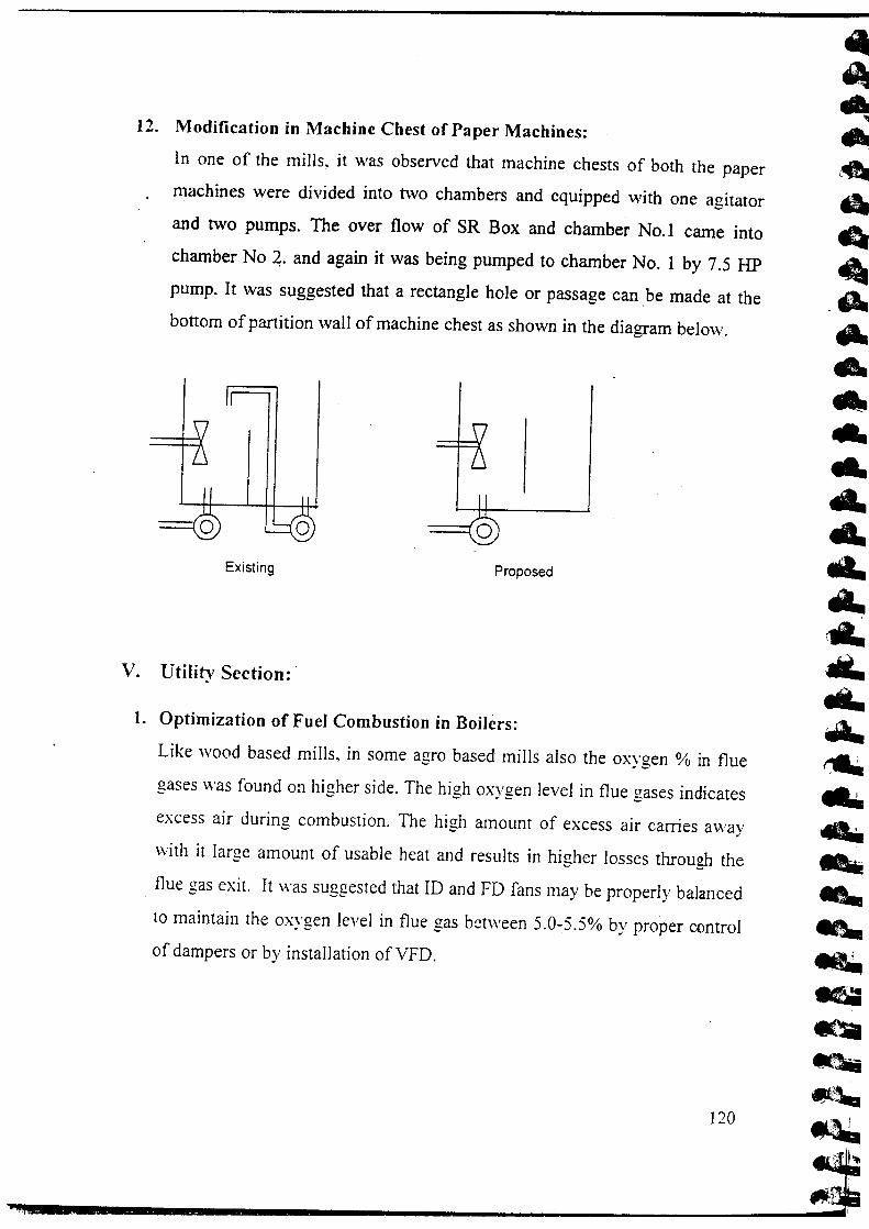
12. Modification in Machine Chest of Paper Machines:
In one of the mills, it was observed that machine chests of both the p
machines were divided into two chambers and equipped with one agi
and two pumps. The over flow of SR Box and chamber No.1 came
chamber No ~. and again it was being pumped to chamber No.1 by 7.5
pump. It was suggested that a rectangle hole or passage can be made at
bottom of partition wall of machine chest as shown in the diagram below.
Existing Proposed
v. UtilitySection:'
1. Optimization of Fuel Combustion in Boilers:
Like wood based mills, in some agro based mills also the oxygen % in fl
gases was found on higher side. The high oxygen level in flue gases indicat
excess air during combustion. The high amount of excess air carries aw,
with it lame amount of usable heat and results in higher losses throuzh tl~ ~-, flue gas exit. It was suggested that ID and FD fans may be properly balance
to maintain the oxygen level in flue gas between 5.0-5.5% by proper contn
of dampers or by installation ofVFD.
12(

2. Feeding of Fuel With Uniform Moisture in Boilers:
During the audit study period of four days in one of the mills, it was
that mill was using rice husk as a fuel in boiler and a lot of varia
found in the moisture level in the fuel being fed to the boiler no.
result the boiler operating conditions were disturbed which ultimate
variation in efficiency. The observations made by the study team
that with in a period of 4 days, there was a variation of 1-2%
performance efficiency only due to variation in fuel moisture. The
variation disturbs the operation and efficiency of dedusting devices a
3. Replacement of Oversized / Under Loaded Motors with Sm:
Motors:
Measurements were taken wherever possible, to ascertain loading
LT induction motors in the plant with the objective of analyzing thi:
identifying under loaded motors. It was pointed out here that the I
efficiency and power factor of under loaded motors comes down re:
wastage of energy. The motors, which were less than 60% loaded,
considered to be under loaded as in this case there is scopes fc
through replacement or reshuffling. However, it is essential to con
type of application that the motor has been put to, before trying to ]
with smaller motor of optimum rating. In this regard, high startir
requirements, frequent process control variations; frequent emerge)
increase requirements, and future plans for capacity hike/ mod
should be taken into account. Considering these aspects, and uru
regular monitoring of under loaded motors, specific case-to-case
should be taken to replace them with smaller motors.I

4. Insulation of Steam and Mud Drums of Boiler:
During the visit in one of the mills, it was noticed that steam and mud dr
of boiler were not insulated. The surface temperature when measurer
CPPRI team was found to be as high as 125°C. This results in high-em
loss through I these uninsulated surfaces in the form of radiation. It
suggested to put proper insulation on the uninsulated areas to reduce the Iloss through radiation.
5. Increasing the Height of Stack Attached with D.G. Sets:
The height of stacks attached with all the three D.G. sets was found near!'~ .the same level of the roof of D.G. rooms when studies were conducted in t
mill. The exit gases coming out from the stack could not raise to pro;
elevation to dispersed in atmosphere. As per the rule the minimum sts
height should be 7 meters and 4.5 meters above the roof of D. G. rooms.
the D.G. sets of 1250 KVA and 500 KVA respectively. It was recommend
that the height of stack should be raised to proper level to control me ;pollution.
6. Insulation of Condensate Returns Line and Feed Water Line of Boilers:
In agro residue based mills also, it was observed that in some of the mil
condensate return line and Feed water line were not insulated.
It was suggested to put proper insulation on all the mentioned surfaces 1
reduce the heat losses through radiation.
7. Reuse of Caustic Used in Regeneration of D.M. Plant:
During the visit in one of the mills, it was noticed that 25 kg of caustic flake
were being used for regeneration of D.M. plant per day. This caustic wa
dissolved in 200 liters ofwater prior to feeding into the resin column. Caustit
used for regeneration was not consumed completely and about 30% caustic
122

remains In the drain water, which was tested and confirmed i
laboratory during visit. It was suggested that drain water after reger
presently, which was going to drain (200 liters) should be collec:
drum/tank and be used in digester.
8. To Stop One Rice Husk Feed Conveyor of Boilers;
In one of the mills, it was observed that fuel (Rice husk) was bein
hopper of boiler no. 4 by two belt conveyors simultaneously. E
conveyors were running at just half of its capacity i.e. approximately
and total running hrs. of-each conveyor was approximately 15 hr/day
recommended to stop one conveyor belt and double the load on tl
conveyor.
9. Optimization of Excess Air in FBC Boilers:
It was observed that oxygen percentage in Boiler No. 4 was on higl
i.e. 11.1% in this mill resulting in excess air of 114%. It was recomme
optimize excess air by proper controlling the damper of I. D. fan & F
and accordingly changing feeding parts & to arrest free air entering
furnace or duct. For this, mill has to install close loop combustion
system in the online O2 sensor system.
VI. Others:
1. Use of Treated Effluent in Place of Fresh Water for the Prepara
Milk of Lime (MOL) in EmuentTreatment Plant:
During the audit in one of the mills, it was observed lthat to increase
of effluent generated from chlorination washer of 'bleach plant {pull
prior to addition with the effluent generated from other sections of the
equalization tank and to further maintain the pH in reaction tank. r
lime (MOL) is used. To prepare tfiis milk of lime (MOL)~ound 2-3
••
of lime and 100 m3 fresh water were beinz used everv day. It was sunnest-- .,.. --that mill can use treated effluent in place of fresh water for the preparation
milk of lime. However, the requirement of the lime may be higher marginal
i.e. 2-3% due to low pH of treated effluent than fresh water.
2. Slogans for Energy Savings:
In most of the mills, it was observed that slogans regarding ener,
conservation were not displayed properly. As the slogans are important toc
to create awareness among the staff members and workers in the industry,
was suggested that energy saving slogans should be written in different are
of plant (especially in the areas of high energy consumption) in simple and
attractive manner. This will motivate the people at grass root level to sa'
energy.
3. Installation of Proper Monitoring Devices to Monitor Section Wi:
Steam Consumption:
During the audit in many mills, it was observed that section wise monitorir
system for steam consumption was not in practice due to which it is vel
difficult to know the area of high consumption. It was recommended that mi
should install proper monitoring devices for proper monitoring of steam flo
rate in various sections. This will help in root cause analysis for the hig
consumption of steam in the particular section.
4. Installation of Water Flow Meter in Feed 'Vater Main Line Instead (
Bypass Line:
In this mill. it was observed that water flow meter was installed in the bypas
line of main reed water line instead of main line in power boiler section. Th:
was entirely wrong. For the correct measurement of incoming water to th
boiler, flow meter should be placed in main line and not in bypass line, whic
12

remains shut for most of the time. It was recommended to change
meter position.
5. Replacement of V-Be It Drive of Vacuum Pump by Flat Belt:
As a general practice, in some of the mills of agro sector are also us
grooves V belts drives to run the vacuum pumps. The major disadv
V-belt is that these absorbs a great deal of useful power and add!
costs. These power losses are typically dissipated in the form of he
in tern has a deteriorative effect on the belt life. It was recommei
vacuum pumps should have flat belt type drive system in place
grooves V belts drives.
6. To Stop 'Vater Leakages in Mill Colony at Different Points:
During the audit in one of the mills, it was observed that there wer
leakages through water supply line, tanks and valves in the paper mil
It was suggested that these leakages should' be stopped on pri
repairing all the leakage points. Meanwhile mill can go for rosn
water supply to the colony to minimize the wastage of water.
7. Use of Fresh Wheat Straw in Place of Stored Wheat Straw in Fui
This mill was using 42% of wheat straw as a raw material in its fun
an annual consumption of 12,000 tJannum..Mill stored a substantial
of wheat straw for its use during off-season. It was also observed
always use the stored wheat straw first and store rest of the incomir,
straw. It was suggested that during the season, mill should use t
wheatstraw directly and store the rest incoming wheJt straw. .

9. Recycling of Waste Water Generated from Potchers:
It was observed in one of the mills that in pulp mill, fresh waterlback w,
was being used to wash the pulp in all four potchers. The estimated quan
of water. was 190 m3/hr, which was going to the anaerobic lagoon at ETP
was suggested to recycle at least 50% of the waste water from potchers
other areas of pulp mill after discarding first 90 minutes water to anaero
lagoon.
10. Optimization of Nutrients Dozingat ETP:
During the audit in one of the mills, it was observed that as nutrients 300
single super phosphate and 200 kg urea were added to aeration tank direc
.once in a day. As the nutrients were being fed directly in the aeration tar
the doze will not remain same throughout the day resulting in an unbalanc
nutrition to the microbes. Therefore it was recommended to dissolve t
single super phosphate and urea in the separate dissolving tanks prior
addition in the inlet of aeration tank after adjusting the flow as per tl
requirement.
11. Modification of Outlet line in Aeration Tank at ETP:
In one of the mills, it was observed that in aeration tank at Effluei
Treatment Plant, inlet and outlet lines were installed at the same side an
were very close to each other resulting in improper aeration of effluent. Th
inlet and outlet lines should be on opposite side to get maximum efficienc
of aerators. Therefore it was recommended to shift outlet point accordingly.
]2(

xx
xxInlet
Outlet~'---------------~[nlet
x xXX
Existing Proposed
12. Replacement of Existing Pumps at E. T. Plant:
During the visit in one of the mills, it was observed that two pu
under operation for pumping the wastewater (from sump pit to
lagoon -10 H P & 7.5 H P and from sump pit to primary clarifier
suggested to install or operate the single pump of better efficiency.
weak black liquor coming from potcher was being pumped to
lagoon by two pumps (10 HP & 7.5 HP). The same quantity of liqu
pumped by single better efficiency pump of 10 H P. Similarly sam
pump can be used to pump liquor from sump pit to primary clarifier.

WASTE PAPER BASED PAPER MILLS:
I. Raw Material Preparation and Handling:
1. Manual Sorting of Raw Material for Cleaning Waste Paper:
During the visit in one of the mills, it was observed that the mi
specific department / persons for sorting of waste paper. Large con
like Iron Wires, Stones, Plastic sheets etc. were sorted out manua
time of loading the material on the conveyer belt. It was recomrr
provide a raised perforated platform at a height of 4 feet, where
paper cuttings, which are likely to have more dirt, are cleaned b~
shaking, so that the dirt will be collected down and cleaned paper wpulping.
2. Raw Material Yard Flooring with Concrete/Brick:
In one mill it was observed that raw material (Waste paper) procui
out side agencies for making the paper was partially stored in cove
and partially in open area and these areas were not floored with
concrete resulted in increased load on cleaning equipments and pooi
of final product due to dirt. It was recommended that raw mater
should be floored either by brick or concrete so that dirt / sand she
enter along with waste paper.
3. Raising the Height of Wall Separating Raw Material Yard andFuel Yard:
In one of the mills, it was observed that the height of the wall, separat
material yard and boiler fuel yard (saw mill waste) was of low
resulting in contamination of dirt in wastepaper. The dirt in raw Il1

increases the load on cleaning equipments (centricJeaners, screens etc.). It
was recommended that the height of the wall separating raw material yard
and boiler fuel yard should be raised, so that the dirt in the form of the sand,
soil. fly ash etc. should not enter along with raw material.
4. Setting up of Permanent Platform on the Side of Waste Paper FeedingConveyor:
It was observed that bales of waste paper were piled on the one side of waste
paper feeding conveyor and used as elevated floor to load waste paper on
conveyor during the visit to one of the mills. It was recommended that there
should be a permanent structure (stair case) for loading the waste paper. Uses
of raw material pile as a raised platform for loading the waste paper on
conveyor not only damages and deteriorates the raw material for subsequent
paper making operation but also leads to safety hazards and may result inaccidents.
5. Bypassing the First Feed Conveyor for the Boiler:
Two conveyor belts were in operation to feed the fuel in the boiler of a mill.
The operation of first stage belt conveyor was of no use. It should be stopped
immediately as it was consuming electric energy to drive the conveyor and
increasing the wear and tear of belt conveyor without giving any benefit. It
was recommended that saw dust feeding point should be brought near to the
second convevor and fuel should co through second belt convevor onlv for., -..... .,;.,;
feeding to boiler hopper.
6. Introduction of Perforated Platform Before the Waste Paper Conveyor:
CPPRI audit team observed that large contaminants like iron wires, stones,
plastic sheets etc. were sorted out manually at the time of loading the
129

material on the conveyor belt in one of the mill visited. As such la
of small contaminants in the form of dirt, sand. plastic chips,
pieces etc. were going with the waste paper in the pulping street I
poor product quality. It was suggested that a de duster (perforate:
should be introduced before the conveyor belt having appropriate p
which will remove some of the dirt and other external contaminam
waste paper stock thereby improving the quality of incoming wasi
hydra pulper.
Waste paper cutting
I Agitator
Existing Practice

....
D···'----------'
I Agit3lor
Proposed practice
7. Replacement of Air Blows System with Belt Conveyor:
It was observed during audit study that the fuel (saw dust) was fed to boiler
through air blower which was equipped with 7.5 HP motor. It was suggested that a
belt conveyor may be installed in place of air blower as the electrical power
consumption in belt conveyor is much less than air blower. 5 HP motor will be
sufficient to convey the fuel to boiler through conveyor belt. To stop the sweeping
of saw dust by wind. conveyor belt may be covered by half portion of waste drums.
8. Replacement of Existing Belt with New Belt of 78 em Width at Waste
Paper Street:
During the visit to one of the mills. it was observed that rollers of hydra-
pulper belt conveyor were jammed and loaded belt just slides over them.
Besides this the width of belt was less (55 em against the 78 em side guard
distance). This resulted in the gap on both sides of belt resulting in the falling
of raw material from the sides of the belt. Some paper got stuck between
rollers resulting in jamming of rollers. The waste paper falling down was
again collected manually and reloaded on conveyor belt. This unnecessary
131

material handling resulted in time and manpower wastage along
housekeeping. It was suggested that belt width should be increase:
so that the gap on both sides could be covered and prevent the fal
of waste paper. The jammed rollers should be made movable at
greasing. This would result in less load on conveyor motor.
II. Pulp lVlillSection:
1. Installation of Magnetic Traps before Refiners in Pulp Mill:
To increase the life of refiner plates the incoming stock should be
iron particles otherwise these particles may damage the bars of plat
the visit in one of the mills, it-was observed that mill was using w:
as raw material and there was chance of having large metallic conta
impurities in the form of nails, pins etc. It was recommended that a
trap may be installed in the inlet line of refiner. The magnetic
magnetic bars inside which can trap the metallic pieces. The magne
cleaned periodically for removing the contents. This will not let
particles to go in the refiner plant.
I Magnetic rods I.
Refiner

2. Insulation of Spherical Rotary Digester:
During the visit to one of the mills, it was observed that milJ has one
spherical rotary digester for cooking of high wet strength waste paper. The
digester was not insulated and this resulted in considerable heat loss. It was
suggested to put proper insulation on the digester to reduce the heat loss
through radiation.
III. Stock Preparation and Paper Machine Section:
1. Convert V-belt Drives to Flat Belt Drives in the Chest Agitator Drives of
Paper Machines:
During the visit to one of the mills, it was observed that chest agitators
running in different chests were driven by V-belt drive. Flat belts being much
more flexible than the v-belts they require less energy for travel around the
pulleys and thus overall energy saving occurs. It was recommended that
chest agitator's drive be modified to flat belt drive system.
2. Increasing the Life of Triple Disc Refiner (TDR) Plate:
It was observed that dirt. sand particles etc. coming with the pulp are going to
refiner in this mill. The mill was using triple disc refiner (TDR) for refining
its pulp. It was recommended that mill should have a proper sorting system
of raw material or should have proper cleaning equipment (like
centricleaners) capable of removing dirt and sand particles, before refiner
resulting in increase in the life ofTDR plate.
3. Use of Thermo-Compressor to Utilize Flash Steam in Proper Manner:
During the audit study in one of the mill, it was observed that in paper
machine there was no flash steam recovery system and condensate along
with flash steam was pumped directly to boiler. The flash steam if recovered
133

properly from the dryer's condensate; can be used In wet end dr
where temperature requirement is less. This will save the live
hence reduce load on boiler house. It was recommended that mill !
thermo-compressor to reclaim low pressure flash steam that is
vented or go waste.
Thermo compressor
4. Insulation of Uninsulated Condensate Tank and Flash Steam
Paper Machines:
Condensate tank and flash steam line meant for the collection of cc
from the dryers were not found insulated in this mill. It was recomrr
put a proper insulation on the condensate tank and pipeline to recloss through radiation.
5. Condensate Recovery from the Steam Shower Pipe Installed fOI
Roll Cleaning at Paper Machines:
DUring the audit to one of the mills, it was observed that there was
shower installed for cleaning the dandy roll. Steam after conde]
shower pipe was coming out from another end of the pipe in the
condensate through a small piece of hosepipe. There was no recoverj
for such condensate and condensate was falling directly to drain in t- - /

of continuous drops. It was recommended that this condensate should be
collected and reused in boiler house or any other suitable place.
6. Improving the Efficiencies of Centricleaners to Improve tbe Paper
Quality:
In one of the mills. it was observed that a three stage centricleaning system
has been installed in the paper machine section but only two stages were
found in operation resulting in improper cleaning of stock. Also the pressure
gauges installed on the centricleaners were out of the order. Therefore it was
recommended that mill should operate all its three stages of centricleaners.
Pressure gauges should be installed at all stages so that proper pressure
difference is maintained to get required cleaning. Also maintaining the
consistency of feedstock is necessary at desired level. The rejects of primary
stage should be cleaned through secondary centricleaners and rejects of
secondary centric leaners should be cleaned through tertiary stage. The final
rejects from tertiary stage should pass through raffler or sand trap to remove
sand and dirt impurities and to recover fiber.
7. Raising the Height of Hood above M.G. Cylinder:
The gap between hood above M.G. and M.G. of paper machine was not
found sufficient. The vapours raised as a result of evaporation from the paper
sheet were brought out through the duct, which was fitted with the fans. In
this mill. it was recommended that the height of the M.G. hood should be
raised to a proper level so that the exhaust of humid air from the hood can be
removed easily. The improper ventilation of vapours from the dryer hood
will result in sheet rewetting and non-uniform moisture profile. This will
result in higher breakage of paper web and production loss. Mill was also
advised to take suggestion from the hood suppliers regarding appropriate
design.
135

8. InstalJation of Pressure Screen in Paper Machine Approach Flo
During the audit in one of the mills, it was observed that pressure s
not provided in the approach flow of paper machine and the mill w:
to provide the same. This will help. in the removal of flakes, plasi
form of film polyethylene etc. coming from bags or wrappers,
including hot melts, pressure sensitive and latex based sticky
debris, dirt, shives, etc. from the stock. which are not removed
centricleaners. It is also helpful in the removal of stickies to sor
from which mill was facing lot of problems.
9. Manual handling of Hydra-pulper Rejects:
In one of the mills, it was observed that the rejects collected in tl
pulper were removed manually. It was recommended that mill shoul
provision of bigger reject outlet on the side of pulper, extended tov
bottom with an hinged door which can be easily opened for takin,rejects.
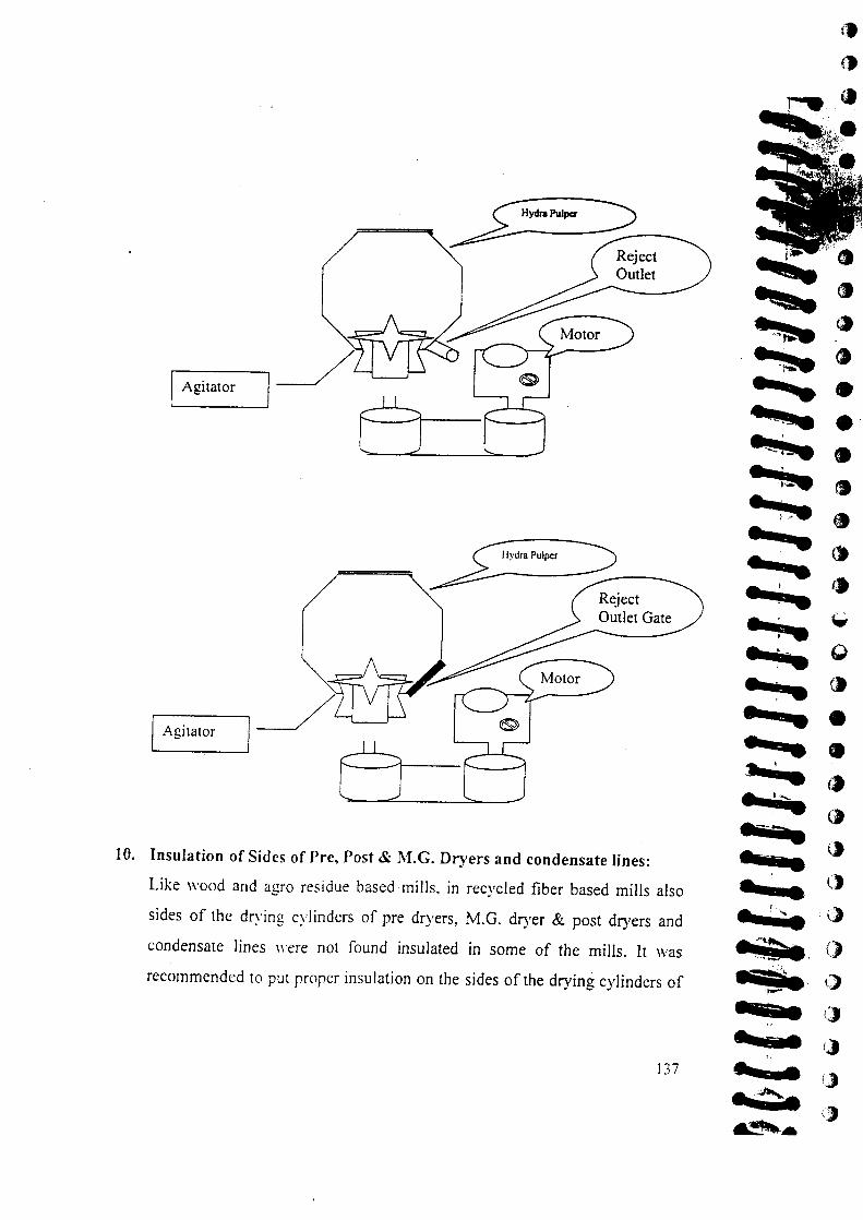
I Agitator
~W'P"'P' ~ _
I Agitator
10. Insulation of Sides of Pre, Post & M.G. Dryers and condensate lines:
Like wood and agro residue based mills, in recycled fiber based mills also
sides of the drying cylinders of pre dryers, M.G. dryer & post dryers and
condensate lines "ere not found insulated in some of the mills. It was
recommended to put proper insulation on the sides of the drying cylinders of
137

pre, post & MG dryer and condensate lines to reduce the heat Ieradiation.
11. Installation of Water Deflectors on Table Rolls:
During the audit to one of the mills, it was observed that no defle
provided on the table rolls to deflect the rimming water from the
nip. As such, the water reamed round the circumference of the roll
the web, thus again increasing the paper web moisture. This inci
load on vacuum element of wire table and suction couch and conseq
presses and dryers. It was recommended that mill should insta
detlectors on table rolls so that rimming water falls down and sfrewet the paper web.
12. Split Sizing in Different layers of Duplexrrriplex Boards:
It was observed that this mill was adding its sizing chemicals in I
chest, which is old and conventional method. Nowadays many m
started split dosing of alum i.e, part of alum is dosed in chemical c
part of it at some other point in approach flow system to get bette
with less chemical consumption. Therefore ir was recommended t
should follow split alum dosing to reduce consumption of rosin salum.
13. Reduction in the Consumption of Rani pal (OBA) by Split Dosing:
As a normal practice in this mill also total quantity of optical brig
agent (OBA) was being added in chemical chest. It was recommend
mill should perform split dosing of Ranipal (OBA). This will bring
20% saving ofOBA without affecting the paper quality.

14. Adoption of Enzymatic De-inking instead of Chemical De-inking:
During the audit to one of the mills. it was observed that mill was performing
chemical de-inking using various chemicals. These de-inking chemicals are
not only environmentally unfriendly but they also affect adversely the fiber
strength. Enzymatic de-inking is an excellent substitution of chemical de-
inking. Therefore it was recommended that mill should explore the
possibility of using the same. Help of CPPRI could be sought for the same.
15. Setting up of Reverse CentricJeaner in Approach Flow System:
It was observed during audit in this mill that particles of thennocoal passed
through installed cleaning system which were deteriorating the quality of
paper and increasing the down time of machine. Since thermocoal is a low
density particle. it cannot be removed by forward cleaner as it passes with
accept pulp. It was recommended that mill should install one leg of reverse
centricleaner for recovery of low density impurities like plastic and
thermocoal. These impurities give sticky problem in dryer section causing
paper breakage.
16. Separate Refining of Imported and Indigenous Waste Paper:
It was observed during mill audit that different grades of wastepaper like
imported ace. Indian ace. sack Kraft and NDLKC 'were used to make
M.G. Kraft Paper. Presently mill is using approximately 50% imported
wastepaper (Imported acC) having long fibres and 50% Indigenous
wastepaper with mixed refining system. It was suggested that during the
manufacturing of unbleached varieties. imported and Indigenous wastepaper
may be refined separately. To get required strength properties in paper,
indigenous waste paper grades requires little refining while imported grades
139

(having soft wood fibres) need more refining. When two grades ;:
together refining leads to deterioration of indigenous fibers
incomplete refining of imported waste paper. In both cases, qualir
will suffer and energy is wasted. It was recommended that separat
of two grades must be carried out.
IV. Utility Section:
1. Optimization of Fuel Combustion in Boilers:
During the audit in one of the mills, it was observed that th
percentage in flue gases of both the boilers was on higher side.
oxygen level in flue gases indicated excess air during combustio
recommended that ID and FD fans may be properly balanced to rna
oxygen level in flue gas between 5.0 - 6.0 % by proper control of da
2. Installation of Economizer in Boilers:
It was observed that the temperature of flue gas at boiler outlet was 1
i.e. 3550
C and 2280 C in two boilers of this mill. The high tempe
flue gases indicated excessive heat loss along with flue gases. The
was recommended that economizer/air preheater may be installed t(
the water/air going to boiler. The temperature of flue gas going
should be around 1500 C.
3. Replacement of Motors Running below the Required Efficiency I
In one of the mills, measurements were -taken where ever pos:
ascertain efficiency of major LT induction motors in the plant 1
objective of analyzing this data for identifying efficiency of motor at
and with load. All the motors tested were found running below the I
efficiency level. It was suggested that these motor be replaced with
efficient motors at the earliest.

7. Removal of Canopy from Stack Attached with Boiler:
It was observed in a mill that the canopy was placed at the top of stack
attached with boiler. It was suggested that the canopy may be removed from
the top of stack because canopy prevents proper dispersion of flue gas in the
atmosphere and also retards the flue gas draft height.
8. Installation of Automatic Tap at Tube Well Line:
It was observed in one of the audits that a tap was provided in the tube well
line near the boiler. Most of the time the tap remained open while not in use,
due to negligence of workers or some fault in the tap. The quantity of fresh
water estimated was around 6 m3/day. It was suggested that the tap provided
in the line of tube well should be changed with automatic tap to save the
fresh water.
9. To Increase the Height of Stacks Attached with D. G. Sets:
It was observed in one of the mills that the stacks attached with both the D.
G. sets i. e. 380 KYA and 320 KVA open at the height of D. G. sets. The
running hours for 380 KYA and 320 KYA D. G. sets were 150 hrs/month
and 100 hrs/rnonth respectively. The Diesel consumption was 52 literslhrs in
380 KVA D. G. set and 48 lit/hr in 320 KYA D. G. set. As per norms. the
stack height for 380 KVA D. G. set should be 3.9 meter above the raofofD.
G. Room and for 320 KYA D. G. set it should be 3.6 meter above the roof of
D. G. Room. By increasing the height of stack, proper dispersion of flue gas
would result in Jess fugitive pollution. Additionally the efficiency of D. G.
sets will beimproved resulting in saving of approximately 2 % in fuel
consumption due to better draft.
141
Installation of Limit Switch at Feed Water Tank of Boiler:
During the audit in one of the mills. it was observed that feed w
water + Condensate) from feed tank of boiler was going to drair
over flow line. It was suggested that over now of boiler feed water i
tank should be stopped since condensate coming from paper mat
high temp (approximately 1000 C). which get mixed with make up s
(ambient temperature) in feed water tank resulting a final temperatui
650 C. By stopping the overflow, about 50 C temperature may be i
resulting in saving of fuel in boiler as well as treated water.
Optimization of Excess Air in Boiler:
It was observed during an audit that oxygen percentage In boiler
higher side, i.e. 11.1 % resulted in excess air of about 114%.
recommended to optimize combustion air by proper controlling the
ofl.D. fan and changing feeding parts accordingly. To arrest free air
into the furnace or duct it was also recommended to use a close
system by installing fuel feeder. Mill was advised to contact boiler
for installation of closed feeding system.
Others:
1. Installation of Agitator at Couch Pit:
During the audit in one of the mills, it was observed that no agita
provided in the couch pit of paper machine. As such the paper fa
couch pit (at the time of paper break on machine) cannot be disintegra
causes high load on pump. It was recommended that mill should iJ
horizontal agitator in the couch pit which would disintegrate th

... -.-
uniformly. A uniformly disintegrated pulp is easy to pump and will cause
less consistency fluctuation.
2. Installation of Section Wise Energy Monitoring System:
During the audit in one of the mills, it was observed that no energy meters
had been installed to monitor section wise electrical consumption. As without
section wise monitoring. it is not possible to find out the area of high
electricity consumption. Therefore it is suggested that mill should install
energy meters in Pulp Mill (Pulper and refiners), Paper machine and Boiler
house
3. The Steam Generation should be Properly Monitored:
To find out the efficiency of boiler it is must to know the quantity of steam
generated by boiler. During the audit in one of the mills, it was observed that
there was no metering device provided in the feed water line as well as in
steam out let line. due to which it was not possible to know the actual steam
production. It was suggested that a flow meter at feed water be installed in
the boiler house. This will help to calculate the efficiency of boiler.
4. Installation of Hot Water Circulation Pump:
In one of the mills. it was observed that condensate coming from paper
machine dryers was collected in condensate tank and pumped back to boiler
house with air pressure from air compressor. This resulted in lowering of
condensate temperature and inclusion of air in the condensate, which may
lead to corrosion in the boiler tubes at high temperature. It was suggested that
this arrangement should be replaced with hot water circulation pump.
]43

CHAPTER-4

CHAPTER - ~
Conclusion:
The study has covered a large cross section of the industry and
many areas where energy saving potential exists. The findings of
would serve as a guideline for the pulp & paper industry to plan th
efficiency drive to achieve cost effective production as well as
energy norms to be notified by Govt. of India under Energy COl
Act - 2001. Study has revealed that by focusing on process optimi
mills can easily achieve these targets for energy efficiency. The stu
shown that largest savings are possible through regular process m
optimization and timely maintenance & upgradation of process eq:
A well-planed energy efficiency drive should be initiated by the
achieve efficiency targets in a phase wise manner.
The improvements suggested in the study may be specific to t
however they represent the overall working of the mills in India. M
to devise strategies for their energy management activities and thes
can help them to understand energy saving potential and identify are
they need to work immediately. In house energy conservation effo
by the mills should also be evaluated for understanding their iII
overall energy consumption. Outside agencies, accredited by Mir
Power, Govt. of India should be entrusted the task to take up the ener
and propose efficiency improvement measures.
For implementation of Energy Conservation Act-200 I. it is necess
process should be audited by the energy auditors as with out process a
is difficult to achieve the suggested energy saving targets. Most of the

audit agencies make their efforts on the utilities area, pump and motors,. . .
which cannot give substantial energy saving options. Mill should find out
such energy auditors who have ample experience in the process auditing in
pulp S: paper industry.
Following process must be covered during future energy management and
efficiency improvement plan by the mills.
• Raw material preparation
• Digester house
• Washing. screening and centricleaning operations
• Bleaching
• Stock preparation
• Paper machine
• Chemical recovery
• Effluent treatment
• Powerhouse
• Other utilities like compressors, vacuum pumps. D. M. Plant etc.
Process simulation &. process integration within the mill can explore many
areas where savings are possible. Process integration is very useful
particularly when mills go for expansion. This exercise can give the details of
total hot S: cold utilities required in the new setup. Therefore the mills after
understanding their process requirements can plan the optimum sized
equipments. Process simulation is another area. which offers significant
saving opportunities. With the introduction of computer controls in the mills,
these tools can be vcrv useful to identify the energy saving areas.
145
In
rs, An analysis ill' cncrgy performance by different mills has shown that in wood
based mills there is potential of significant savings in raw material
preparation & handling section, pulp mill. stock preparation and chemical
recovery sections without making major changes in process & equiprnents.
Similarly in Agro based IIIilis there is large potential in pulp mill section and
stock preparation & paper machines. In the waste paper based mills stock
preparation & paper machines require most of the efforts. Apart from these
electrical. Utilities and power house also offer significant savings. The
studies conducted in this project have given an overview of the energy
performance in mills and highlighted the areas of requiring attention. Since
no two mills are identical in process layout and technological studies,
therefore no common strategies can be adopted for improvement of energy
efficiency. however the experience and efforts made in one mill can form a
guide line to be followed as per the requirement & mill conditions. Section
wise saving potential carried out at different mills is enclosed as annexure - II
9ut
od
Jy
'ill
of
er
~d
nt
's,
[5 146

ANNEXURE

"••"I((
I{
'-"••,"••'"--~
"••••-.~
••••~
"JIll)
I(
Co.
I(
I(
~
Annexure- I
List of mills;
LARGE WOOD BASED PULP AND PAPER MILLS;
1. Mis Seshasayee Paper & Boards Ltd. Erode (T.N.)
2. Mis Tamil Nadu Newsprint & Paper Ltd .. Distt. Karur, (T.N.)
3. MIs Ballarpur Industries Ltd. (BIL T). Unit: Ballarpur, Distt. Chandrapur (Maharashtra)
4. Mis Ballarpur Industries Ltd. (BILT). Unit: Shree Gopal, Yamuna Nagar (Haryana)
5. Mis The Sirpur Paper Mills Ltd., Sirpur - Kaghaznagar (A.P.)
AGRO BASED PULP AND PAPER MILLS;
6. Mis Shreyans Industries Ltd., Ahemadgarh (Punjab)
7. Mis Kailash papers, Aghwanpur, Distt. Moradabad (U.P.)
8. Mis Yash Papers Ltd., Darshannagar, Faizabad (u.P.)
WASTE PAPER BASED PAPER MILLS;
9. Mis Kalptaru Papers Limited, Tal. Kalol, Gandhinagar, Gujarat
10. Mis Well Pack Papers & containers Ltd., Vamaj, Tal. Kalol, Gujarat
11. Mis Rainbow Papers Limited, Ahmedabad, Gujarat
12. MIs Karan Paper Mills, Chhatral, District - Mehsana, Gujarat
13. Mis Shelavi Pulp & Paper Mills Pvt. Ltd., Chhatral, District - Mehsana, Gujarat
14. Mis Plaza Papers Pvt. Ltd., Village Ghunna, Behat Road, Distt. Saharanpur (V.P.)
It"
W-
e••Il.-

Annexure -II
Section wise saving potential car ried out at different mills;
LARGE WOOD BASED PULP AND PAPER MILLS
SI Raw Material I Pulp I Stock Chemical I Electrical Effluent Others" TotalNo. Preparation I Mill" I Preparation Recoverv " " Treatment (Rs. in
and Handling I and Paper . I " Lacs)• I I :\-l:Jchine* I
1. 328.00 i ·UO.O I 59.20 323.05 118.87 - 47.50 11872. 46.60 ! 22-L4 i - I 1.15 ! 24.08 I - 252.00 5483. 220.00 10.25 16.66 132.82 I - 0.50 14.16 2744. 13.12 I 1.37 I 64.71 r 116.73 ! 6.67 - 117.57 3205. 8.93 ! 248.0 ! 226.0 I 18l.00 19.63 5.13 30.00 709
AGRO BASED PULP AND PAPER MILLS
SI Raw Material I Pulp Stock Chcmical Electrical Emuent Others" TotalNo. Preparation M m- Preparation Recovery • . Treatment (Rs. in
:nd Handling I and Paper " Lacs):\-Iachine"
1. 41.07 179.63 17.51 34.24 16.37 - 31.45 2372. 33.00 I 1.92" 1'8.81 - 0.82 - 11.82 663. 24.53 135.10 2.50 - 16.69 3.72 6.50 79
WASTE PAPER BASED PAPER MILLS
SI Raw Material Pulp Stock Electrical Effluent Others" TeblNo. Preparation Mill" Preparation . Treatment (Rs. in
and Handling and Paper • Lacs)• Machine"
1. 1.00 - 13.26 329.00 - 88.21 4312. 18.87 - 50.76 5.65 - 14.30 903. - 1.00 25.32 9.03 - 13.48 494. - 19.40 33.57 - - 3.65 575. 3.30 0.50 13.25 - - 8.08 256. 0.96 0.98 0.56 2.08 - 19.07 24
*AII figure indiating Rs. Lacs per annumSL No: Indic:aling Mill as per listed in annexure-IOthers: Inc:. Power Boiler. OM plant. process improvement etc
..

Annexure - III
COMPREHENSIVE QUESTIONNAIRE FORMILL DATA & INFORlVIATION
For
ENERGY PERFORl"IANCE EVALUATION ANDOPTIMIZATION IN PULP & PAPER
INDUSTRY
BY
CENTRAL PULP AND PAPER RESEARCH INSTITUTESAHARANPUR, U. P., INDIA
www.cppri.org.in
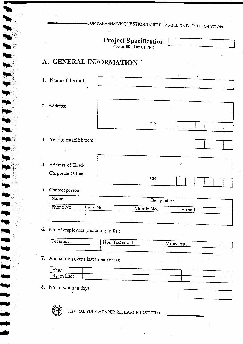
•••••••••••••••••",.--.:-,••••••••••~'/'"
~\~f:;j.,;,;:;'
••••"';;;~'.
•••••••••••••.•,-,".,.••.:..-~'-- ";""-",.,'i.,"; "•••.;~.
•••. f
•••••• t't:
••••••••••••••••••••....,•••••rb
•••-••
------COMPREHENSIVE QUESTIONNAIRE FOR MILL DATA INFORMATION
Project Specification(To be filled by CPPRI) ~--_J
A. GENERAL INFORMATION
1. Name of the mill: '-------~---'--_J2. Address:
PINI I I '1 I 1
3. Year' of establishment:
4. Address of Head!
Corporate Office:PIN
r 1 1 I I 1
.'
5. Contact person
Name DesignationPhone No . Fax No. Mobile No. E-mail·
6. No. of employees (including mill) :
Technical. .1 Non Technical Ministerial .I
7. Annual turn over ( last three years):
Rs. In Lacs
8. No. of working days:~
{~~} CENTRAL PULP & PAPER RESEARCH INSTITUTE..•..•.

~
~ ..
~
•••••••••••••••••"••.-
••.',.••...~ ..-(•.,'
It·-:·~..'.~::;~.;:.~~~••.:,.
r . " .....~;;','
~~'l,~.,
1&II:.
•tfit•••
- COMPREHENSIVE QUESTIONNAIRE FOR ~1!LL DATA I0iFOR:-'lATI00
B . lVIILLDATA1. Installed capacity, tJa
1..,Actual production, tJa
I.3. Capacity utilisation, % :
I4. Raw material furnish, % :
Grade of Paper Raw material furnish. %I I I II I I II I
,II I I II
I I I5. Raw material consumption, tJa:
[--:~:--:w--.:..M_a_t_er_ia_l_+-- -+- 2 __ l 3__ -+ 4__ -+-__ 5__
6. Quality I grades of paper produced, tla:
S1. Gradel Quality tJaNo.12 .3 I456
7. Energy consumption
Particulars Max. Min. Avg.Water consumption, rrr'zt p: I
Steam consumption, tit p
Electricity consumption ,kWh It p:
I.,
• CENTRAL PULP & PAPER RESEARCH INSTITUTE
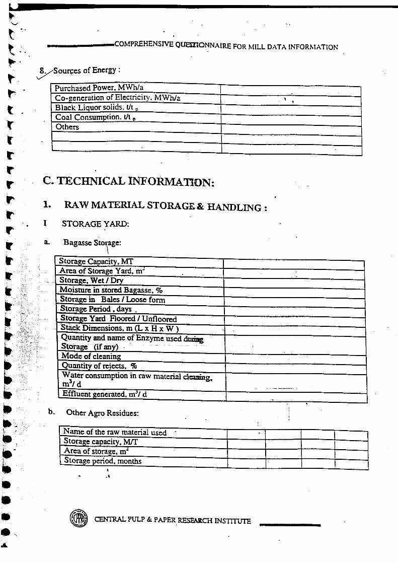
~.\....'t .,"t .:~.t,~.
t .'trr~
r~
t'
"IfrIf
'.'. ~
It->,;,,~,_~'f/r<' " ,.'.'~it- :i;;i~;'~-
~ '.: •• r}.- .
~.'i .lit•••~)--••••••.,
_____ --,COMPREHENSIVE QUEDJONNAIRE FOR MILL OATA INFORt-.tATION
y-Sour~es of Energy:
Purchased Power. MWh/a .Co-generation of Electricity. MYVhh t ,Black Liquor solids. tit 0
Coal Consumption. tit D
Others
C. TECHNICAL INFORMAnON:
1. RAW MATERIAL STORAGE.&: HANDLING:
I STORAGE YARD:
a. Bagasse Storage:t,
Storage Capacity. MTArea of Storage Yard. rrr'Storage. VVet/I>ry.Moisture in stored Bagasse. %Storage in Bales I Loose formStorage Period. days *
-Storage Yam Floored I UnflooredStack Dimensions. m (L x H x W )
"
Quantity and name ~f Enzyme used dwiDgSt()rage--(if an)') - ....--.-
Mode of cleaningQuantity of rejects. %Water consumption in raw material dcmmg.ml/d
.' ..-.-~.--.Effluent generated. m~1d . .
b. Other Agro Residues:
Name of the raw material used . .Storaze capacity, M!fArea of storage, rrr' IStoraze period. months I
-,
CENTRAL PULP & PAPER RESEAR.cHINSTITUTE
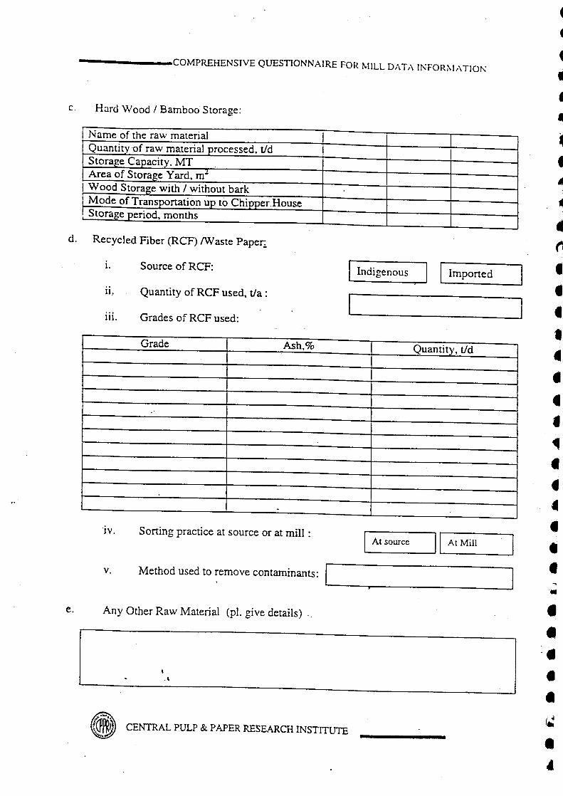
-------COMPREHENSIVE QUESTIONNAIREFORMILLDATAINFOR~IATIOT\
c, Hard Wood / Bamboo Storage:
Name of the raw materialQuantity 'of raw material processed, tid IStorage Capacity, MTArea of Storage Yard, m"
I Wood Storage with / without barki Mode of Transportation up to Chipper Houser Storage period, months
d. Recycled Fiber (ReF) !Waste Paper;
i.[Indigenous I I Imported
Source of ReF:
11. Quantity of RCF used, tla :
111. Grades of ReF used:
Grade Ash,% Quantity, tid
-'iv. Sorting practice at source or at mill : I At source II At Mill
v. Method used to remove contaminants:
e. Any Other Raw Material (pI. give details) "
,,,
~'IU'.{~f~)) CENTRAL PULP & PAPER RESEARCH INSTITUTE.!'.,.~"I.
44
4
••••••~
•tiI
•••••••~••••••'.••'.•••4

•-.: -
•••'-It-••••••••••••••-.••.,It ..".~- .0' .<'
••It·lit .••••••~"~':."-. .',~:'
••LatpIIIt ~",oit\j
~,; ...",,;~~,,.,
-.•••••;" .••
-------COMPREHENSIVE QUESTIONNAIREFORMILL DATAINFQR~Ir\TIOl"
RAW MATERIAL PREPARATION:
a. Bagasse
1.
11.Whether Depithing at Mill siteDepither Details
MakeNo. of DepithersCapacity of each Depither, tidMode of Depithing ,Wet / dryMoisture during depithing, %Quantity of bagasse, d~ithed. tidPith, %Screen size (diameter) .mrnEnergy Consumption kWh / t for depithing BagasseStack Dimensions, m (L x H x W)Quantity and name of Enzyme used during StorageMode of Transportation up to Pu!g MillEnergy ConsuJI!ption, kWh/t for Handling of BagasseMode of disposal / utilisation ofpith
b. Straw:
Type of straw usedQuantity of straw processed, tidType of cutters
..
No. of cuttersThrough put of cuttersEnergy consumption during cutting,kWhlt strawMode of cleaningQuantity of rejects, %
Water consumption in raw material cleaning, rrr'/dEffluent generated, rrr'/dRecirculation of effluent, Yes/ No (If yes, %recirculation)Ener-gy consuJI!ption during cleaning, kWhlt strawMode of disposal/ utilisation of rejects.
,.4
~.-.ll1lDlil, CENTRAL PULP & PAPER RaEARCH INSTITUTE'~f.

-------COMPREHENSJVE QUESTIONNAIREFORt\lILLDATAINFORl\lATIOl\:
c. Other Agro Residues:
Name of the raw material usedIQuantity of raw material processed. tid I I
Type of cuttersINo. of CuttersIMode of cleaning
Effluent generated during raw materialcleaning, m3/dRecirculation of effluent, Yes/ No (Ifyes, % recirculation)Mode of conveying raw material todigester ,Qty of rejects generated, %Mode of disposal/utilization of rejects
d. Wood / Bamboo
I. Details of chipper house
Name of the raw material usedQuantity of raw material processed, tidMoisture content in raw material, %Type of ChipperMakeNo. of ChippersChipper Capacity tIhTotal chip production, tidMode of FeedingTotal Running hours, hrs.l dElectrical Consumption kWh/t wood
IDust generation, %Mode of disposal/utilization of chipper dust
11. Chip screening
.Type of screenMakeAccept Chip dimensionsLength, rnmWidth, rnrnThickness, .mrn 4,Chip Accept, %
{~r~~CENTRAL PULP & PAPER RESEARCH INSTITlTfE,,~_#.

,-...•••~--
••••••II
•••••••••••.,•It"It:,· .
T:~·••1It-
••)'•t-Ilt ,~j.ii....'. ····P!':-
"'" ~; \>:~:-::"
••• }\;_/i~-
"';;:.-•••
-------COMP~HENSIVE QUESTIONNAIREFORMILLDATAINFORt--I,\TIOi\
3. PULP MILL
1. Pulping process employed:Mechanical I 1L...__ C_h_e_m_i_c_a_1_-.,;]
a. Mechanical Pulping
1. Refining Details
Name of the raw material refinedIQuantity of raw material processed, tid!No. of refinersiMake/type of refiner,iElectrical consumption, kWh/t pulpIPresteaming temp.,uC and time, hr.IChemical applied, %IWhite liquor temp. "C,
Sharpness and pattern of refiner platesTemperature of refining, . "CGap between refiner plates, mmRate of feeding through refiner, tlhrSpeed of refiner plates, rpmStages of refining (two/three stage)Refining - Atmospheric / PressurizedPulp consistency, %Freeness rise, . U SRI CSFScreening patternCleaning patternBleaching Sequence
11. Details of Bleaching Stages
Bleaching stage% Chemical additionon pulp .pH
Ternperature.X'Time, hrs.Consistency, %
, .,
_«j) CENTRAL PULP & PAPER RESEARCH INSTITtITE

-------COMPREHENSrvE QUESTIONNAIREFORMILL DATAINFORI\IATIOf\
iii. Pulp Characteristics & Energy Consumption in Bleaching
Initial Pulp Brightness, %Final Pulp Brightness, %Bleached pulp yield, %
Electrical consumption, kWh/t nuln
Steam Consumption in bleaching section, tit CUfD
b. Chemical PUlping
i. Pulping process employed SOda] Kraft
n. Raw material used
Raw Material Quantity tid
....-
111. Type of digester used 1...._B_a_tc_h J I Continuous 1
a. Batch Digester Details:
Type of digesterNo. of digestersCapacity, rrr'Loading capacity, %Chip Feeding Mode ,
.'
CENTRAL PULP & PAPER RESEARCfI INSTITUTE
~
••••J
••

••~'- .
t---
•~
t-t
•tt
•••tta•••.~••••t
"i,i'~',•,.1ft~-- .
•~
••t:•: ·~ttt:~~::....
_______ COMPREHENSIVE QUESTIONNAIRE FOR MILL DATA INFOIUvlATION
I Chi~ Reject, %
e. Waste Paper
1. Sorting I By hand I I Shredded I11. Method used for
removing Manual I I Mechanical r Icontaminants
As such
As such
f. Others
i. Mode of cleaning I Manual I I Mechanical I I As such
ii. If by mechanical means
Make and type of equipmentCapacity, tJ hr.Material processed. tidRejects, %
• CENTRAL PULP & PAPER RESEARCH INSTITUTE

\.,\w ..-v\.;- .
\..\W.\..\w-.\,~\.,
'-"-''-'I\.,~,,'~ 'i1Ui~:,:':c
~.
~.
~.
"-"--~
t~.
jr
----
-- COMPREHENSIVE QLTESTIONNAIRE FOR 1\1ILL O.-\T:\ I0iFOR:'-I..\TIO:"
I. Batch Cooking Details:
I Digester type & capacity. rn' I I IName of the raw materials used I IQuantity of raw material
Iprocessed, tidRaw material to digester (o.d )t/batchActive alkali charge, Kg/batchWhite liquor charge, rrr'Active alkali in white liquor, gilLiquor fill to digester, rrr' IDirectiIndirect steaming I ,
Chip moisture, %Bath ratio IBlack liquor fill, rrr'Effective Alkali charge (asNaOH)%Chip filling time, minutes.Steaming time to temperatureTotal cooking timeH factorInitial temperature °CCooking temp. °CRetention at maximumtemperature, minutesPulp Yield, %Kappa No.Blow temperature (batch) °C "
Blowing timeSteam requirement, LP, tit eulo
Steam requirement, MP tit puln
Electrical consumption, kwh/t oule
Mode of Blow Down (open tank! .blow tank)I
11. Blow heat recoveryIf yes, Yes
IVolume ofwater, m3/d ,t
. Temp., °C --Ir----· -~-I~.-.~.~~MCENTRAL PULP & PAPER RESEARCH INSTITUTE

-------COMPREHENSIVE QUESTIONNAIREFORMILL DATA INFORMATIOl\:
b. Continuous Digester Details:
Name of the DigesterNumber of digesters
II
Capaci!l', tLoading capacity, %Dimensions -No. of tubesLength, mDiameter. m
i.Continuos digestercooking details:
a. Raw material used
Raw MaterialQuantity, tid
b. Cooking conditions
Street] 2Raw material moisture, %
White l!guor charge tI hr.White Liquor active alkali, gilBlack liquor charged t / hr.Black Liquor residual active alkali. gilRetention time, min.Temp.ocL!guor to raw material ratioH factorK'!Ppa no. I .Pulp yield unbleached, %
- .L P Steam flow, tlhr.MP steam flow. tlhr.Electrical consumption KWh! dayType of blow down I
CENTRAL PULP & PAPER RESEARCH INSTITUTE
f«~
•4
•~
•- .t
•••••~
•••••\J
••-

r
--It••••It
•••••••••••••••.---
."--.-•·"•It.'•~-,.-Itja••~:";~:;;~"" '
____ --COMPREHENSIVE QUESTIONNAIREFO[~~IILL o.,T.-\ [:\FOR~l.-\TIOi"
c. Blow heat recoveryI Yes
If yes,
Volume of hot water Igenerated, m3/dTemp.,oC I I
~'IJCENTRAL PULP & PAPER RESEARCH INSTITUTE..

~,.-,.
•••••----•••••••••••••••••••••••••••••••••••....•/'.
"' ··f
_______ COMPREHENSIVE QUESTIONK·\IRE FOR :-'IlLL U.\T:\ J:-':FOI~~I.\TIO:\
..II. Waste Paper / Secondary Fibre Processing
a . Source of ReF:__ I_nu_'i_gc_n_()u_~ __ II __ I_rn_r_o_n_cd_---,l
b. Quantity of ReF used. tJa :.
c. Grades of ReF used:
Grade I Ash'7c I Qtv. tId II
II
I
III
d.IL...-A_t_so_u_r_ce' I I At mill siteSorting practice:
e. Method used to remove contaminants:
Parameters Pulper, HD Deflaker Turbo Coarse FineHClLe Cleaning separator screening screening
No. of unitsCapacity, tlhr.Operating cy. %Opening size,mmofHDCleanerPressure drop in .HD cleaner, mmScreen ,Perforation, mm ,Nature of rejects& their, %Rejects, %Energyconsumption,kWh/t pulp
(@k) CENTRAL PULP & PAPER RESEARCH INSTITUTE
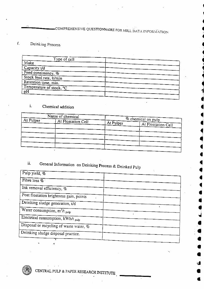
-------COMPREHENSJVE QUESTIONNAIREFORl\lILL DATAJ~FOR\fXTJOl\
f. Deinking Process
I Type of cellMake
1 Capaci!y tid, Feed consistency, %
Stock feed rate, ItlminRetention time, min.Te~erature of stock, DC
..EH
1. Chemical addition
Name of chemical% chemical on pupAt Pu!£er At Floatation Cell At PUlper At Floatation Cell
11. General Information on Deinking Process & Deinked Pulp
Pulp yield, %
Fibre loss % .
Ink removal efficiency, %
Post floatation brightness gain, points
Deinking sludge generation, tid .Water consumption, m"/t pulp
Electrical consumption, kWh/t pulp
Disposal or recycling of waste water, %
Deinking sludge disposal practice.
•..
~ CENTRAL PULP & PAPER RESEARCH INSTITUTE~
4
1
~
444
•~'I
4~
~
1••••~.,4•4••••••
~
•••••\J
••

r~
••••••••--J
~
••••Pt,~•••t·~
••••It.'•••~'.
~,i..II' "je_>:""
~ .. '
f -c•.::'1",j;,~~J:.,
~~.,~'
•••
-------COMPREHENSIVE QUESTIONNAIRE FORMILL DATA INFORMATION
4. <, WASHING / SCREENING / CENTRI -CLEANING ANDREFINING OF UNBLEACHED PULP
I Brown stock washing:
Type & noDrum speed:Stock inlet flow rate.t/hrStock consistency, %Dilution factorHot/ cold water washingSoda loss at BSW - 3/4Energy consumption, kWh/t pulp
II Pulp Screening
Number of vibratory screensScreen hole diameter, mmConsistency of feed pulp % -Quantity of rejects tlday
rReject ash %Rejects re-cooked/soldNumber of centrifugal/ pressurescreensScreen hole dial slot width mmConsistency of feed pulpQuantity of rejects tldayRe-cooked 1 recycled/ sold
,
III Centricleaning.
No. of cenlicleaning stages 314 stage .Consistency of feed pulpQuantity of rejects tlday.Re-cvcled/sotd
IAny other type of screenin!!lcleaning
~ CENTRAL PULP& PAPERRESEARCHINSTITUTE

{~~@CENTRAL PULP & PAPER RESEARCH INSTITUTE...
~
1
t~
~
••.~
4~
~
•1••••4••41
••••41
•••-4•••••~
••
-- COMPREHENSIVE QUESTIONNAIRE FOR ~nLL DATA INFOR~I:\TIO!'
IV Pulp refining
I Type of refinerMakeNumber of refinerRefining consistency ,
Initial/final freenesRefining power

•'-••••-.~-'---"•••••••••••••••••••It
••••••,. ;y.....:!'I'~~'i-:'••••• ">;:~;i';':'-"•• ':;C/,
-. .'1~~
••t.;~i!fl~(Ill"', ?,-; r,
fa"".Ia: /'••
-------COMPREHENSIVE QUESTIONNAIREFORr-.nLL D:\Tr\ INFOR:-'J..\TIOi\
5. PULP BLEACHING:
1. Bleaching process/sequence employed:
II. Bleaching chemical applied. kg/t pulp:
NaOH Hypo Others
ill. Bleaching Conditions:
Bleaching Chemical. pH Temp, Retention Consistency,Stage % °c Time, hrs %
IV. Bleached Pulp Characteristics & Energy consumption In Bleaching
Brightness of bleached pulp, %lSOViscosity of bleached pulp, g/cmJBleaching loss (pulp shrinkage),%Quantity of bleach plant effluent generated ,mJ/t nuln
Recycling/reuse of bleach plant effluent, % .Steam consumption in bleaching section, tit DulD ,Electrical consumption .kWhIt nulD . I
;
I,
., CENTRAL PULP & PAPER RESEARCH INSTITUTE
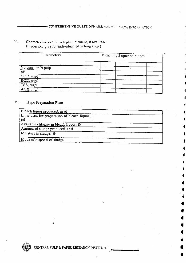
------_CO~1PREHENSIVE QUESTIONNAIREFORt-lILLDATAI?\FOR~J..\TIOr-:
V. Characteristics of bleach plant effluent. if available:(if possible give for individual bleaching stage)
I Parameters Bleaching Sequence. stagesI
IVolume. rrr It pulppHCOD, rng/lBOD, mgllTSS, mgllAOX, mgll
•
VI. Hypo Preparation Plant
~
•f
f
~
f~
••f44t
••~
•••~
••
Bleach liquor produced, rrr'zdLime used for preparation of bleach liquor,tidAvail able chlorine in bleach liquor, %Amount of sludge produced, tIdMoisture in sludge, %
Mode of disposal of sludge
~PJPl CENTRAL PULP & PAPER RESEARCH INSTITUTE •t

-.,-.•••••-.\f," "
"••"••••••"•"••••••':';;-i" •
•• ;'jr.'-~}"--;"":~j~,;'"',,'. ':~'f>'• '''if
tr.....,;.~(J!:,•. tl,~X;'i>"
;),;~
ia•• );-'~~~,,~i
1&.,' .Ii "I: -;,},. ',;,.-,,'. .
[I
t>~;~ ..
l-I-"~l'.::<•• ···:·r·.
:r~~.l~}.-.·'.'~
-------COMPREHENSIVE QUESTIONNAIREFORMILL DAT,\ INFORi\I:\TIO:"
6.'STOCK PREPARATIOl'; & PAPER lVIACHINE
. 1. Refining
Particulars 1 2 3 4Type of refinersMakeNo. of refinersBar shape & size
i
Presence or absence of dams IMetal of refiner plateLife of refiner plate .% Wear of refiner plateRefining consistency, %Temperature, °CpHInitial pulp freeness, °SR or CSFFinal pulp freeness, °SR or CSFRefining power kWhit or hp-day/ton
II. Major furnish Components :
[__N~_~~tl1eI~I:----I~-;---I_.III. Chemical additives in StockPreparation
Major Chemicals
Chemical Type Amount used (Kglt D) Point of additionFillers .Rosin sizeAlum
,Wet strength agentDry strength agentOptical brightnersRetention aidDyeAny other ,,
CENTRAL PULP & PAPER RESEARCH INSTITUTE

-------COMPREHENSIVE QUESTIONNAIREFOR~IILLDATAINFOR~I:\TIO:"\
IV. Details of centricleaner
Type of centricleaners ,,No. of cleaning stagesICleaning consistency, %IInlet pressure differential desiJ!ned/operating. Kglcm2
Outlet pressure differential ,designed/operating,KJ!/cm2LeJ! diameter, mmReject flow rate, rrr' / dReject consistency , %Type of contaminant removedMode of disposal of centricleaner rejects
,
V. Pressure Screening
Type of screenType of perforationCleaning consistency, %Size of hole/slot, mmRate of reject from screen ,%Type of rejectEnergy consumption, kWh/d
PAPER MACIDNE SECTION:
I. Details of Paper Machines
Paper Machine I 2 3. 4 5No.1 Name
Type ofM/cMake
i
Capacity, tid
/'(Designed)Production, tid(actual)Product! gsmDeckle,rri .,'Speed, m1rnin
<,
...•.{~f~\ CENTRAL PULP & PAPER RESEARCH INSTITUTE
'(00,
••41
••••.-t

,••-."--.-"---It•~-.••--•"1.1,
•• c
-----.-,.~
~.
I
-------COMPREHENSIVE QUESTIONN.-\/RE FOR~.lILLD,\1:\I~rOR.\I.\TiO.',
ElectricityIconsumption,I
kWh/t II I
Steam, t/t, I
II I
I I IIQuantity of I
, Imachine backwater e . m3/too I IPoints of use of
·1paper machineback water i
Quantity of backI I Iwater used at each
point I , IType of waterused in sealing ofvacuum pumps &
<
extent ofrecirculation ofsealing waterType of inplantfiltration/purification system forpaper machineback waterFiber loss, kg I t p
Type of save allused for fiberrecovery% of fibre .
recovered from thesave allPoint of use ofclarified waterfrom save allEnergyconsumption inrunning save all,kWhldRecycling of papermachine backwater, %
I,
~~~) CENTRAL PULP & PAPER RESEARCH INSTITUTE

DL--------------------------------rrr·f"r,.rt·rrt,p
r,.•It
.-••••,-.-1~.
~.'-.;.-....It.i... ...·~1~..:'~;•
-------COMPREHENSIVE QUESTIONNAIREFORMILL DATA INFORMATION
a. Head Box
'paper Machine No. I 2 3 4 5Type of head box
IConsistency range in head box. %
I -Consistency regulation(Manual/Auto)Slice opening .mrn
Head of stock, mm
b. Wire Part
Paper Machine No. 1 2 3 4 5Type of wire usedShake mechanism, if anyNo. of elementsWidth of wire ,mmType of couch rollDryness after couch roll ,%Consistency of white water, %Type of driveDrive energy consumption inrunning wire ,kWh! t,Fiber recovery system
lSI Pass Retention, %
..1. Type and number of dewatering elements on wire table
Paper Machine I 2 3 ~ 5No. I -f!ydrafoilsVacuum aidedVacuum boxesH}'drafoilsTable rolls ,
{~) CENTRAL PULP & PAPER RESEAR~H INSTITUTE

---- COMPREHENSIVE QUESTIONNAIRE FOR MILL DATA INFORMATIOr-.:
c. Press part:
Paper Machine No.INo. of presses!Type of pressIVacuum in suction press.rnrn hz
Nip load at press .Kg/crnMaterial of press rollsType of felt usedDryness after each press, %Electrical energy consumption. kWh/t n
d. Dryer Part:
Paper Machine No. 1 2 3 4 5Type of dryin£ cylindersNo. of dryersDrying capacity of dryer cylinders, ~gwater removed IhrSteam pressure .k£/cm~Type of dryer fabric usedWhether equipped with heat recoverySystem, YeslNo If yes, type of hood
Dryness of web before entering thedryer, %Final dryness of web, %Type of condensate removal systemOverall condensate recovery, %Power requirement, kWh/tp
•
e. Size Press:
Paper Machine No. I 2 3 4 5Type of size press .Position of size press (after which dryergroup)Dryness of web before size press, %Size pick up, g/mDryness of web after size press, %Power requirementl kWhit D
{~f~~CENTRAL PULP & PAPER RESEARCH INSmUTE\..;

•,,-••"""-.,••••.,•,••••••.,•·"
.':' b.• ~>ji"',j."
a;','! ,'. ;\~;)T",;
• .i
••""'''-••j'~"
~'.,ffI~'-tt~--••.:~~:'~.
----- __ COMPREHENsrvE QL'ESTIONNAIRE FOR ~lILL D,\T.\ INFORi'-l:\TI01\
f. Calendar :
Paper Machine No. I I I ..., I 3 I 4 I 5 !
!Type of calender I I I IINo. of calender rolls I I IIWorking nip load
I I IPower requirement, kWhit 0
I I i
g. Pope Reel
l~p~:=~_er_M~a~ch~i~ne~N~0~ +- r__2__ +1 __ 3--l~--4------5--~, Tree of pope reel [ . _
Rewinder
5Pa er Machine No. 1 2 3 4T e of rewinderPower re uirernent, kWhlt
.\ ..
,CENTRAL PULP & PAPER RESEARCH INSmUTE
..... ",
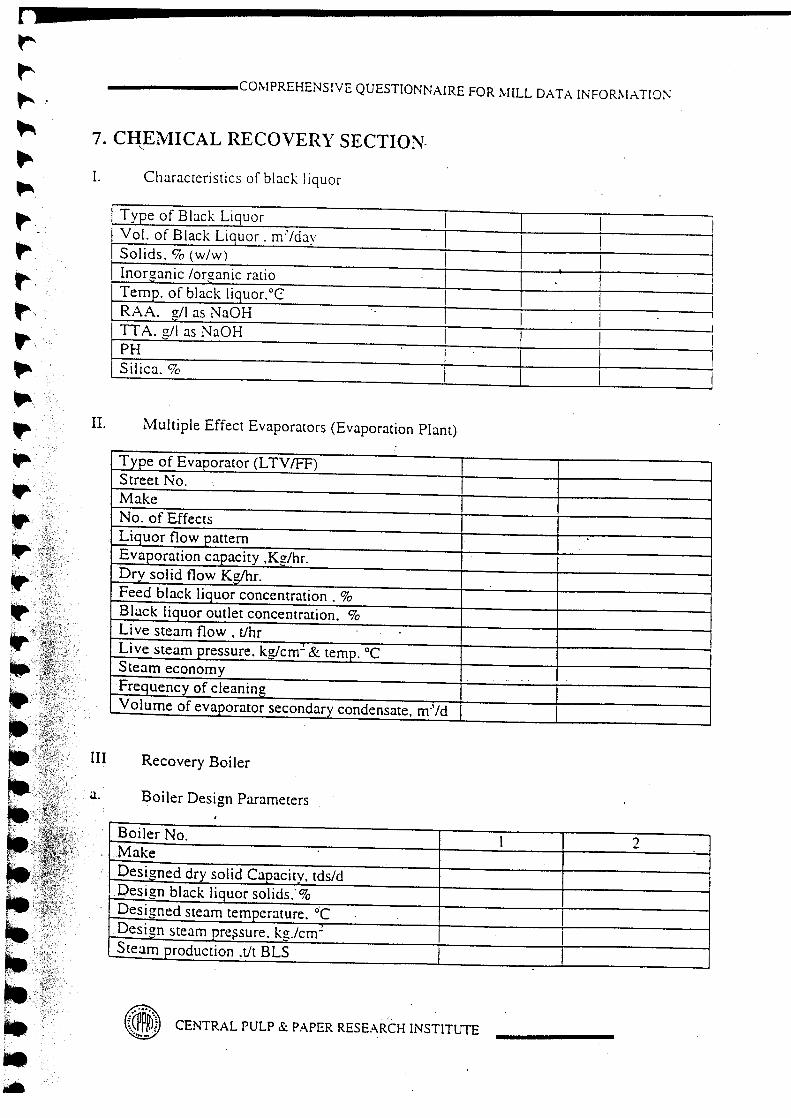
na•• ----------------------------------t'~
~
••••~
~,..•. ,
~\
t',•. '
~.,..••••~
"-.'.p,'-,: -><~;;y
p ,;~~~.,.
IP••••••••t····,...t..-.,...•,..fitlilt,.,. .T.t. :;".~:,1•••••
-------COMPREHENSIyE QUESTIONNAIREFORMILL DATA INFORMATIOj\;
7. CHEMICAL RECOVERY SECTION.<,
L Characteristics of black liquor
Txpe of Black Liquor I IVol. of Black Liguor. m'zday I ISolids. % (w/w) I IInorganic /organic ratio I ITemp. of black liquor.°C: I I IRAA. g/l as NaOH I I I ITT A. g/l as NaOH I I !PH ISilica. % I
II. Multiple Effect Evaporators (Evaporation Plant)
Type of Evaporator (LTVIFF)Street No.MakeNo. of EffectsLLquor flow patternEvaporation capacity .Kg/hr,Dry solid flow Kg/hr.Feed black liquor concentration. %Black liquor outlet concentration. %Live steam flow. tfhrLive steam pressure. kg/em" & temp. °C ISteam economyFrequency of cleaningVolume of evaporator secondary condensate. mJ/d
III Recovery Boiler
a. Boiler Design Parameters
Boiler No. 1 2.Make
Designed dry solid C'!Eacity. tds/dDesign black liquor solids.' %Designed steam temperature. -cDesign steam pressure, kz.zcrrr' ISteam production .Ut BLS
~ CENTRALPULP& PAPERRESEARCHINSTITUTE

---- COMPREHENS1VE QUESTIONNAIRE FOR ~IILL DATA I0:FOR:-'I,\TIO:"
b. Boiler Operating Parameter
Boiler No. I 1 I ") I!
Black liquor firing, tds/d ISteam pressure ,kg/cm-Steam temperature ,DCSteam flow .t/hr.Primary air, %Prim~ air temp ,DCSecondary air ,%Secondary air temperature ,DCTertiary air ,%Tertiary air temperature ,DCFlue gas temp after economizer, DCHigher heating value of black liquor solids·,KCall KgBlack liquor solid before mixing tank, %Chemical losses to stack ,kg/tReduction % dsSmelt from the boiler, t Na20/d
IV. Causticisation
Lime requirement t/daySmelt from the boiler, t Na20/dGreen liquor from dissolver, ,mJ/d'IT A of green liquor gil as Na20Type of slakerCapacity, tid IWeak white liquor, m'/dWhite liquor to storage, m'/dTotal active alkali of White liguor , gil as Na20 .Quantity of lime sludge produced, tidMoisture content in lime sludge, %Mode of disposal of lime sludge
CENTRAL PULP & PAPER RESEARCH INSTITUTE

r
---•••••
--••,
••"••••••••••••~
••\•.'•.-:~\~-:(.', .'r:;
.,.'.~3'-lit·••~-
~~.:.
,-C._.' ... __ ..... :.:::.::_.<;.':.,;_<_ ... ;......•
~;>t;~);,~!:·:~;~,~·,~..
_______ COMPREHENSIVE QUESTIONNAIRE FOR I\IILL U.\T:\ I:\FO!{\1.\TIO!\
'-V, Lime Kiln
I Lime kiln desizn canacitv. UhfI Len zth m ' , .::-
Diameter. m !Type of Coolinz for Lime.No. of coolers ILime sludge feed. tfhr 'Temperature of lime sludze, °CCaCO~ in lime sludge. '70 ILoss on Ignition ( LOI )of lime sludge. %Lime stone or lake shell feed. tfhrMoisture in lime stone. %Furnace oil, feed, lit (lime produced)LOI ofSPM, %Lime produced; tfhr.Temperature of lime. °C
{~~~) CENfRAL PULP & PAPER RESEARCH INSTITUTE~

••••••"••"• VIII.
••litIt a.
I
It
••~
"••.#••••••••• 'c
""", ;;-;,,.j!~)_~~__-_-,_'_,c·') ..
'-'. \('
•
r---_ i::-~'
, ". - 'Z:".~'Ia-t-, '" -'-.:;<
~~;
II,..~J
t;!~IIt..;/·~:\:T'."," t· - '"-_~ •
-- COMPREHENSIVE QUESTIONNAIRE r:OR MILL DATA INFOR7\l..\T!O~,
ETP sludge generated tid: Primary [ ] Secondary
Sludge characteristics:
Sludge dewatering device, if anyIConsistency of dewatered sludge, % ._ .. ..
IMode of disposal of ETP SludgeI
,.,
~.-.~~~ CENTRAL PULP & PAPER RESEARCH INSmUTE~"...
. I
I I

f
Ja
•••••••t•tt
•It•I•""
••••••·'::,"•~;'•~.
It
••t,.••tit·t~<
------..,,_COMPREHENSIVE QUESTIONNAIREFOR:VULL DATAINFOR:-'!.-\nON
8. EFFLUENT TREATlYIENT PLANT
I. Min"Quantity of effluent discharged, m3/d:D
Source of waste water generated:
Max Avg
II.
a. eb fc gd h
III Flow rate measurement device:
IV. Brief details of Pretreatment facilitiesavailable ,if any:
v. ETP details:
Paniculars Type Dimensions, Capacity, Retention Performancem m3 Time, hr. Efficiency, %Primary
ClarifierAnaerobic/Aerobic Pond!LagoonAeration Tank(ASP) .SecondaryClarifierPOlishing PondOther treatmentfacilities, if any
"'" ow sheet ETP s stem• U:::U.le attach 0fl if y
• CENTRAL PULP & PAPER RESEARCH INSTITUTE
'!'.;~..•.J;.,,"." v. ·",t,II•.J.~: •.."': t .•.••' ''l: ~ •. "
, ....I

Area of land irrigated with treated effluent •.hectares
~
4
••~
4t~
4~
~
tt
••4
•4
•4
••4•••~
41
•t
••••••
-------COMPREHENSIVE QUESTiONNAIREFORMILL DATAINFORI\lATIO/\:
VI. General Characteristics of Influent and Effluent :
Characteristics Influent EffluentTemp, VcpHTSS, mgllTDS, mgllChlorides, mgllBOD. mgll .COD. mgllAOX.mgnSAR.Colour, Pt.Co unitPhosphates,mgllNi trogen,mgll
VU. Mode of Discharge of treatedeffluent:
Inland (canal or river) J I Onland discharge Ia. On land discharge:
No. of years the land has been used for irrigationCrops grown in effluent irrigated area
1. Soil characteristics before and after irrigation with effluent
. Characteristics Before Irrigation After Irrization
. . \
~M~'CENTRALPULP & PAPER RESEARCH INSTITUTE•....~~
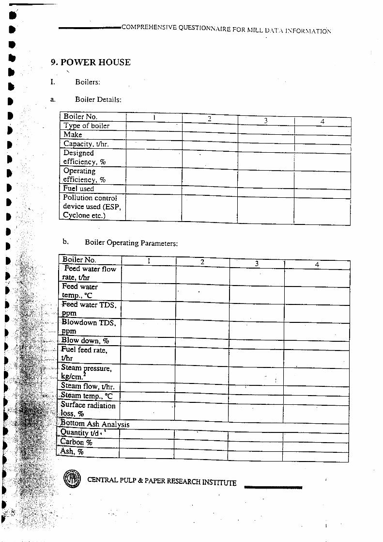
•II••.,.,••••••t•It
•IttIt~;./
t
••~
~
-~ ...•'.~.I,
~,.'~,•
_______ COMPREHENSIVE QUESTIONNAIRE FOR r-IlLL OXL\ l:--.:rOR:--!r\TIOi\
9. POWER HOUSE
1. Boilers:
a. Boiler Details:
Boiler No. 1 ., .., I 4j
Type of boiler IMakeCapacity, t/hr. IDesignedefficiency, %Operatingefficiency, %Fuel usedPollution controldevice used (ESP,Cyclone etc.)
b. Boiler Operating Parameters:
2 3 4
sis
8 CENTRAL PULP & PAPER RESEARCH INSTITUTE

-------COMPREHENSIVE QUESTIONNAIREFORMILLDATAINFORMATIOt\'
F!y Ash Analvsis!Quantity tidICarbon 9c
Ash,90ISPM, rng/Nrrr'
(at stack)
c. Flue Gas Analysis
.Oxygen,%Carbon Monooxide, %Carbondioxide,%Temp.oC
d. Fuel analysis
Name of the fuelCarbon, %Hydrogen, %Oxygen, %Sulfur, %Volatile matter, %Ash, %Moisture, %Gross Cal. Value,Kcallkg
.
,,,
• CENTRAL PULP & PAPER RESEARCH INSTITUTE

.,
•••••••••f;-••r..~
~It-It_.,Itr,,·It.~ ...' (I)":,~Jl~k~.:'i:";,:":. .: ' ~,.",':.-4.;";4ir;;~;,.';;~'; ':" -.~:).-:.... -~.:,0,: ,-,., ,,'''''' .;',.
•••.,
••""••••••It•••••••
_______ COl\IPREHENSIVE QUESTIONNAIRE FOR i\lILL DATA I;\FOR,\LHIO;\
II. .,Co-Generation:
a. Total Co-generation. MW
c. No. of turbines
c. Details of turbines
Turbine No. I 1 I 2 I 3Type I IMakeYear of installation .Capacity, MW /dProduction, MW/dInlet steam' presure,kg/cm2
Inlet steam temp. °CInlet steam flow, t/hr.Outlet steam pressure,kg/cm2
Outlet steam temp. °COutlet steam flow, t/hr.Condensate flow, t/hr .
CENTRAL PULP & PAPER RESEARCH INSTITUTE
.'"':.'..