Embed Size (px)
Citation preview

JPS POWER SYSTEM INTEGRITY INVESTIGATION
REPORT OF THE INVESTIGATION COMMITTEE
INTO
THE PUBLIC ELECTRICITY SYSTEM SHUTDOWN
OF AUGUST 5, 2012
AND
RELIABILITY OF THE POWER GRID
February 5, 2013

JPS Power System Integrity Investigation
System Shutdown of August 5, 2012
OUR Doc: ELE2013001_REP001 i
JPS POWER SYSTEM INTEGRITY INVESTIGATION

JPS Power System Integrity Investigation
System Shutdown of August 5, 2012
OUR Doc: ELE2013001_REP001 ii
EXECUTIVE SUMMARY
Over the last six (6) years, electricity customers island-wide, on four (4) occasions, experienced extended power outages resulting from a complete shutdown of the Jamaica Public Service Company Limited (JPS) Electric Power System. These outages occurred on the following dates and for the reasons indicated:
1. July 15, 2006 – failure of distance relays to operate at Duncans substation following a lightning strike to the Duncans/Bogue 138kV transmission line.
2. July 3, 2007 – due to non-clearance of a fault on lightning arresters for Unit # 2 generator step-up transformer at JPS Old Harbour power station when one pole of the 138kV circuit breaker in the switchyard failed to open properly.
3. January 9, 2008 – due to non-clearance of a fault on the Duhaney/Tredegar 138kV transmission line at the Tredegar substation end after a wooden transmission support pole fell to the ground.
4. August 5, 2012 – due to non-clearance of a fault at pole #1 on the Duhaney/Naggo Head 69kV transmission line at the Duhaney substation end.
The first three (3) incidents have been the subject of OUR Enquiries which set out various recommendations to be implemented by JPS.
The OUR reviewed the JPS preliminary Technical Report(s) on the August 5, 2012 System shutdown and determined that it was necessary to carry out further investigations regarding this shutdown incident, as well as the integrity of the Power System. In consequence the OUR appointed an Investigation Committee (the Committee) comprising members of the OUR’s technical staff along with experienced professional consultants to undertake the aforementioned investigations.
In addition to enquiring into the August 5, 2012 incident, the Committee was required in summary, to undertake all necessary analytical actions in a timely and professional manner to, inter alia:
1) Determine JPS’ compliance with earlier Directives issued by the OUR and the resultant impacts in relation to the System failures which occurred before August 5, 2012.
2) Review and evaluate JPS’ policies and practices governing the provisioning, commissioning, operation and maintenance of Power System protection facilities.
3) Assess the overall Power System reliability, stability and vulnerabilities; and the capabilities and application of the Power System monitoring and control facilities;

JPS Power System Integrity Investigation
System Shutdown of August 5, 2012
OUR Doc: ELE2013001_REP001 iii
4) Make recommendations for appropriate preventative and remedial measures to protect and enhance the reliability of the electric Power System.
The Committee has carried out its duties and the results are contained in the sections below.
OBSERVATIONS AND CONCLUSIONS
The factors leading to the total System shutdown on August 5, 2012 are typical of those which precipitated the three (3) earlier System shutdowns, including the first major incident on July 15, 2006. While the initiating circumstances are different in each case, the underlying sequence of System collapse from generators and transmission circuits tripping follow a familiar and parallel path.
Human error and maintenance short-comings have played a part, as well as manifested deficiencies in the island-wide grid and generation infrastructure. Indeed, in some instances the problem could be viewed as an “accident waiting to happen” given the propensity of the deficiencies and weaknesses to easily precipitate a total System shutdown.
With this background in mind, the Committee has reviewed the JPS “Conclusions and Recommendations” for remedy of several issues identified as associated with the current System shutdown and supports their plans and proposals. However, in addition to the JPS items, the Committee has identified a significant number of other factors, which are extensively listed below. Also, those factors considered to be of particular priority to the on-going integrity of the grid and affecting the reliability of supply to customers have been focused on separately in Section 5 entitled “Issues Critical to System Integrity.”
The Committee makes the following observations and conclusions:
1. The initiating cause of the August 5, 2012 System shutdown was due to a permanent 3-phase fault on Pole #1 located on the Duhaney/Naggo Head 69kV transmission line, probably as a result of a lightning strike to the pole or adjacent shield wire, given the then existing inclement weather conditions prevailing as a result of Tropical Storm Ernesto.
2. The fault was not cleared promptly within the Critical Fault Clearing Time (CFCT) because the trip circuit of the Micom P441 primary protection distance relay at Duhaney substation installed on the Duhaney/Naggo Head 69kV transmission line was taken out of service due to a prior observed mal-function of the relay.
3. The inordinate delay of four (4) months in replacing the defective Micom P441 trip circuit is to be primarily blamed for precipitating the subsequent island-wide system collapse.

JPS Power System Integrity Investigation
System Shutdown of August 5, 2012
OUR Doc: ELE2013001_REP001 iv
4. The backup directional overcurrent protection which was in service on the Duhaney/Naggo Head 69kV transmission line did not operate in time because of the inverse time delay characteristics of the relay, leading to a cascading effect which caused a System collapse.
5. The failure of protective relays at Duhaney substation to quickly clear the fault led to the operation of Zone 2 remote clearance of all of the 69kV tie-lines in the Corporate Area connected to the Duhaney substation and in consequence caused full separation of generating plants in the Kingston region from the rest of the island.
6. The Corporate Area network subsequently collapsed from a combination of under-voltage situations impacting the auxiliary services of Jamaica Private Power Company (JPPC) plant and the JPS Rockfort barge diesel generators, as well as, subsequently, a high voltage state on the 69kV busbars of West Kingston Power Plant (WKPP).
7. The remainder of the grid linking generators at Old Harbour, Bogue, hydro plants and wind turbine generators also collapsed after a sub-separation, caused from a combination of generator trips led by the JEP diesel generators on loss of auxiliary supplies and frequency distortions which initiated protective relay operations on various transmission circuits.
8. The inherent inability of the primary protection scheme on the 138kV side of the main bulk power transformers at Duhaney substation to detect and respond to a fault on the 69kV side, as well as the absence of backup protection on the same 69kV side significantly contributed to non-clearance of the fault for the Rural Area subsystem which subsequently led to the collapse of that subsystem.
9. The Duhaney 138/69kV substation is a major weak link in the integrity of the transmission system as it serves as the only connection between generating plants in the Corporate Area and those in Old Harbour, as well as Bogue power station located in the North West of the island. Any failure of either the 138kV or in particular the 69kV infrastructure at the substation is likely to precipitate an island-wide System shutdown.
10. The protective relaying system for the Duhaney substation needs a complete review to remedy the weaknesses of the 69kV radial lines, 69kV busbar and 138/69kV transformer protection schemes, in respect of which there appears to be no backup protection installed on the 69kV side of the transformers.
11. The 69kV single busbar arrangement at Duhaney substation requires some form of physical reconfiguration in order to facilitate isolation of sections of the busbar in the event of a fault on either side.

JPS Power System Integrity Investigation
System Shutdown of August 5, 2012
OUR Doc: ELE2013001_REP001 v
12. The Zone 2 backup distance protection on the New Twickenham/Duhaney 69kV line failed to trip, it is clear that the configuration or relay settings on this transmission line is amiss and needs to be urgently remedied.
13. There is an urgent requirement to strengthen the 138KV network so that strong direct links are available to tie the main generating plants to each other, preferable with contingency paths for power flow during a crisis, it is noted that while customer loading has doubled, no major upgrading of the 138kV transmission infrastructure has taken place in thirty (30) years.
14. Initial analysis suggests that neither the operation of the present Under-Frequency Load Shedding (UFLS) scheme or adequate spinning reserve on-line during the start of the recent major grid disturbances, would have averted a total system collapse.
15. All the diesel generators installed on the system including JPPC, JEP and WKPP units have very limited “Ride-Through” tolerances in instances where a System disturbance results in transient low voltage conditions due to early tripping of the auxiliary service supply busbars.
16. Based on JPS standard protection settings for low voltage ride-through capability, made available to the Committee, WKPP generators should have tripped on the under-voltage condition which affected the plant’s auxiliary busbar similar to other diesel generating units in the Corporate Area Power Island formed during the System separation.
17. Given the sequence of System shutdowns where diesel generator trip-outs have played a critical role, in addition to the units established susceptibility to voltage fluctuations, there is an implied need to examine whether the multitude of medium speed diesel generators existing on the system is further compounding grid stability. Questions are raised in connection with the machine inertia constants, governor controls and dynamic voltage regulation, among other factors.
18. The current philosophy for grid restoration based on JPS documented policy and operating instructions currently in place appears satisfactory to adequately address System restoration procedures following a partial or complete shutdown of the System. However, the System restoration policy appears not to include a provision for a full analysis of the shutdown to be undertaken by technically competent personnel prior to grid restoration activities, in specific instances when the reason for the System shutdown is in doubt.
19. The existing line-to-ground (L-G) fault MVA values for the 69kV busbars in the Corporate Area Zone, particularly at Hunts Bay power station and Duhaney substation are very high, which could negatively impact the Critical Fault Clearing Time, therefore efforts should be made to reduce these values.

JPS Power System Integrity Investigation
System Shutdown of August 5, 2012
OUR Doc: ELE2013001_REP001 vi
20. On-going tests and maintenance of all manual and automatic synchronizing equipment installed on the grid should be made a priority.
21. The “write-over” of data on some critical protection relays is a major obstacle to a full and complete analysis of technical problems following a System disturbance, JPS needs to find a remedy as soon as possible.
22. Recommendations emerging from earlier System shutdown Enquiries for the installation of dual batteries at select critical grid facilities, was not acted upon by JPS.
23. The dispatch of MVARs from generators, the automatic/manual control of 69kV capacitor installations and the maintenance of correct voltages on 138kV and 69kV busbars island-wide particularly at light loads by JPS System Control operators appears to be a problem and the relevant policy needs to be reviewed and appropriate training undertaken where indicated.
24. There is a concern relating to the current policy and procedures governing the dispatch of MW and MVAR by the System Control operators to ensure that IPPs always operate under the dispatchers guide and in strict compliance with the agreed practices, embedded in the Generation Code, PPAs and other relevant codes and standards.
25. Many Sequence of Events (SOE) Recorders required to facilitate proper System operation are not installed or where installed are non-functional. JPS needs to develop an action plan and promptly effect implementation, given that this matter has been an issue since the 2006 System shutdown.
26. It is noted that accurate Global Positioning System (GPS) time synchronizing of all critical System monitoring and data recording equipment is essential to effective System operation. JPS needs to effect early installation where indicated, given that this matter has also been an issue since the 2006 System shutdown.
27. It was observed that the on-going maintenance and availability of Digital Fault Recorders installed on the grid was not being accorded priority, since many of them were found to be out of service during the August 5, 2012 System disturbance. Data from these devices are critical for fault analysis.
28. The JEP 138kV single tie-line interconnection to the JPS grid at Old Harbour with total 124MW of diesel generators, poses a serious risk to grid stability since the mere tripping of the tie-line breaker for any cause will possibly remove a significant block of generation from the System, thereby violating the established N-1 security constraint of maximum of 60MW of lost generation.
29. There appears to be no clear and effective management method in place to follow up on the remedying of dysfunctional critical items of grid equipment

JPS Power System Integrity Investigation
System Shutdown of August 5, 2012
OUR Doc: ELE2013001_REP001 vii
and other System defects, items can simply “fall through the cracks”. Management staff needs to be held more accountable when such incidents occur.
30. It is noted that the parameters, particularly the inertia constants of the engine/generator sets of the IPPs and possibly JPS generators used for planning and stability studies are not the actual values of the machines, but rather typical values, an update of generator parameters with actual values is therefore needed.
31. It is noted that international accepted practice of periodic tests for generating machines are not being undertaken for generators in the Power System, full load and partial load rejection tests, along with other standard mandatory operational machine tests should be conducted on all JPS and IPP units on a periodic basis within a five (5) year time span.
32. Given the critical nature of the availability of the communication network to the on-going reliability of the grid protection and monitoring systems, all efforts should be made by JPS to effect early completion of plans for full redundancy of alternate signal and data routing in the event of failure of the default path.
33. A review indicates that the power-flow into the New Twickenham 69kV substation seems to follow a circular path, between Duhaney, Old Harbour and Tredegar, JPS needs to examine this and consider whether or not opening one of the 69kV lines to New Twickenham may be a more suitable mode of operation.
34. Full SCADA visibility of monitored and controlled apparatus installed on the grid is crucial to reliable operations, JPS needs to ensure near 100% up time and promptly fix any identified defective component of the system as soon as possible.
35. JPS had reported ‘Black Start’ issues with some of the IPPs, this has however been denied by the respective entities. Nevertheless, it is felt that every attempt should continue to be made to ensure that all plants equipped with such facilities keep the start-up machines in good working order.
36. The Generation Code which sets out the agreed policy and procedures governing generation operations between JPS and the IPPs is not yet enacted, this needs to be fast tracked.
37. Given the impending increase in IPP connections to the JPS grid and other determining factors, consideration should be given to the development of a separate “Generation Inter-connection Code” (components of which are already in use) which does not form a part of the current Generation Code, in order to better focus on the issues inherent with the inter-tie arrangement between JPS and a current or future IPP or IPP/customer.

JPS Power System Integrity Investigation
System Shutdown of August 5, 2012
OUR Doc: ELE2013001_REP001 viii
38. The Transmission Code which similarly sets out the principles and practices for JPS operations covering System planning, engineering design, operations and maintenance for the transmission system is not yet completed, this needs to be expedited and promptly implemented given its overall importance to System integrity.
39. It is important that consideration be given to the review and expansion of current systems of monitoring JPS and the IPPs, including follow-up on items crucial to System integrity arising from previous System shutdown Enquiries and Investigations.
40. It is necessary for the OUR to establish and chair an on-going “Grid Reliability Committee” to include the major stake holders, JPS and the major IPPs, in order to focus on and expedite issues related to System integrity.
41. It is necessary that the OUR be vested with the authority to impose sanctions on regulated entities in the Electricity Sector in instances of serious breaches under the OUR Act or in a situation of on-going non-compliance with the Directives of the OUR. In consideration of this, a detailed study of the issues involved should be conducted by knowledgeable legal experts and other relevant professionals in order to remedy the likely impediments inherent in the framework for the imposition of such sanctions.
42. There is a recognition that the OUR should commit itself to an on-going regulatory overview of actions recommended by the various Enquiry Panels in the recent past and ensure that the relevant items are executed expeditiously by JPS or respective IPPs.
In preparation for future incidents, it is the opinion of the Committee that the OUR should prepare a list of standard precursor actions which JPS and IPPs should take after the incident in order to preserve the evidence as far as is possible. Such items would include the taking of appropriate pictures, safeguarding of cross-arms, insulators, etc. removed from poles, or any other damaged apparatus, as well as all data recordings during the incident and subsequent restoration of power.

JPS Power System Integrity Investigation
System Shutdown of August 5, 2012
OUR Doc: ELE2013001_REP001 ix
RECOMMENDATIONS
The Committee has extensively reviewed the detailed submissions from JPS and IPPs, responses to specific questions raised, as well as other relevant documentation. The Committee made certain observations and arrived at a number of conclusions, as a result of which it made the following Recommendations.
Jamaica Public Service Company Ltd
JPS should urgently carry out the Recommendations made in their report entitled “Technical Report Power System Shutdown - August 5, 2012” dated September 28, 2012 (see Appendix 1).
In addition, the specific recommendations of the Committee are as follows:
1) Urgently review the protective relaying configuration for Duhaney substation to remedy the weaknesses inherent in the protection schemes for the 69kV radial lines, 69kV busbar, 138/69kV transformers backup protection and the apparent malfunction of the Duhaney/New Twickenham transmission line protection.
2) Commission a study to be undertaken by independent evaluators on the necessity for the installation of a second station battery and/or communication battery at critical substation and power station switchyard locations island-wide.
3) Evaluate recommendations for down-grading the Duhaney substation given its present potential to seriously compromise the grid integrity and either cause or adversely contribute to a total Power System collapse.
4) Conduct planning studies to evaluate an apparent need to upgrade and strengthen the 138KV grid so that robust direct links are available to tie the main generating plants to each other for support island-wide and reduce the possibility of grid separation during major System disturbances.
5) Engage the services of experienced and qualified professionals to conduct a detailed assessment of the dire and unacceptable problem with “Ride-Through” tolerances of generators on the System, including low voltage protective schemes and settings; affecting in particular, the medium speed diesel generators and make specific recommendations to guarantee that the generators do not trip off spuriously and unnecessarily during major System disturbances, a copy of which should be made available to the OUR.
6) Carry out a study to determine the cause of the transient rise in voltage in the Corporate Area following the grid separation resulting from the August 5, 2012

JPS Power System Integrity Investigation
System Shutdown of August 5, 2012
OUR Doc: ELE2013001_REP001 x
System shutdown which caused the tripping of WKPP diesel generators and undertake remedial actions.
7) Revise the current JPS System restoration manual to include analysis by competent technical personnel in situations where the initiating cause of an outage is not apparent, prior to restoration of the System.
8) Evaluate the recommendation to un-ground some of the generator step-up transformers located in the Corporate Area with the objective of reducing the 69kV single line to ground (S-L-G) fault levels.
9) Ensure that the maximum fault clearing time setting for primary and backup protection at all busbars deemed critical to System security does not exceed the Critical Fault Clearing Time (CFCT) for that busbar.
10) Implement a program of on-going tests and maintenance on all manual and automatic synchronizing equipment installed on the grid.
11) Review and remedy the current problem with “write-over” of data on critical protection relays.
12) Undertake discussions with manufacturers and conduct whatever research is necessary to understand the reasons for the non-operation of some of the Under-Frequency Load Shedding (UFLS) schemes, when the System is subjected to severe disturbances.
13) Comprehensively review the overall UFLS scheme, taking into consideration
the feeder/load characteristics for peak, partial peak and light load conditions.
14) Review the current policy and procedures covering the dispatch of MW and MVAR by the System Control operators to ensure that IPPs always operate under the dispatchers guide and in strict compliance with agreed practices.
15) Review the policy and procedures for dispatch of MVARs from generating units, the automatic/manual control of 69kV capacitor installations and the maintenance of correct voltages on 138kV and 69kV busbars island-wide undertaken by JPS System Control operators, particularly at light loads.
16) Develop an action plan and promptly effect in-service implementation of all Sequence of Events Recorders required to facilitate proper System operation.
17) Immediately implement time synchronizing of all GPS systems installed on the grid and at power stations, which was previously recommended and is long overdue.
18) Ensure the repair, on-going maintenance and availability of all Digital Fault Recorders installed on the grid.

JPS Power System Integrity Investigation
System Shutdown of August 5, 2012
OUR Doc: ELE2013001_REP001 xi
19) Ensure that full simulator training of System Control operators in System recovery techniques for partial or total System shutdown is undertaken and repeated at intervals.
20) Ensure that System Control Centre maintains an on-going log of crucial System defects which is copied to all responsible maintenance management personnel.
21) Examine options and implement physical changes to the existing JEP 138kV single tie-line interconnection to the JPS grid at Old Harbour which supports a total of 124MW of diesel generation, in order to provide a second 138kV link to the Old Harbour switchyard.
22) Implement a program wherein full load or partial load rejection tests, along with other required routine operational machine tests are performed periodically on all JPS and IPP generating units above 5MW capacity within a five (5) year time span.
23) Ensure that the parameters, particularly the inertia constants of the engine/generator sets of the IPPs and possibly JPS generator units used for planning and stability studies reflect the actual values of the machines.
24) Conduct a study to evaluate the impact of the multiple smaller capacity medium speed diesel generators versus the conventional steam/slow-speed diesel machines on System stability.
25) Complete the implementation of plans for full redundancy of alternate communication signal and data routing in the event of failure of the default path.
26) Review the possibility of circular power flows between Old Harbour, Tredegar, Duhaney and the New Twickenham 69kV substation.
27) Ensure that full SCADA visibility of monitored and controlled apparatus installed on the grid is a priority objective and that a near 100% up time is maintained.
28) Ensure that all plants equipped with “Black Start” facilities keep the start-up machines in good working order.
29) Ensure that the Generation Code which sets out the agreed policy and procedures for generating operations between JPS and the IPPs is complied with.
30) Cooperate with the OUR to examine the appropriateness of developing a “Generation Inter-connection Code” in respect of which components are already in use, as a separate document from the Generation Code.

JPS Power System Integrity Investigation
System Shutdown of August 5, 2012
OUR Doc: ELE2013001_REP001 xii
31) Complete the Transmission Code which is in the draft stage and implement promptly.
Independent Power Producers (IPPs) JEP, WKPP & JPPC
1) Ensure that all diesel generation plants equipped with Black Start facilities are kept in an “available on call” condition with the start-up machines in good working order.
2) Cooperate with JPS and its agents and consultants in the conduct of the assessment of issues related to the “Ride-Through” capabilities of its generators.
3) Support the implementation as required of all the provisions of the Generation Code.
4) JEP along with JPS examine options and implement physical changes to the existing JEP 138kV single tie-line to the JPS grid at Old Harbour which connects an aggregate of 124MW of installed diesel generation.
5) WKPP to carry out checks on relay configuration and settings to determine whether the protection scheme is operating correctly for low voltage conditions.
Office of Utilities Regulation (OUR)
1) Review and expand the present method of monitoring JPS and the IPPs, technical operations and maintenance, including follow-up on items crucial to System integrity arising from previous System shutdown Enquiries and investigations.
2) Employ third party consultants or other technical experts to conduct periodic audits into the technical functioning of aspects of the JPS and IPPs operations.
3) Convene and chair a “Grid Reliability Committee” to include the major stake holders i.e. JPS, the major IPPs and any other participant considered appropriate.
4) Ensure through its regulatory oversight authority that the Generation Code which binds JPS and the IPPs to a common and agreed set of technical commitments and operating practices for generation, is enacted and its specific provisions observed by the parties.

JPS Power System Integrity Investigation
System Shutdown of August 5, 2012
OUR Doc: ELE2013001_REP001 xiii
5) In consultation with JPS, examine the appropriateness of developing a “Generation Inter-connection Code” in respect of which components are already in use, as a separate document from the Generation Code.
6) Ensure that early completion of work on the Transmission Code is undertaken by JPS.
7) Prepare a list of standard precursor actions which JPS and IPPs should take after a System incident in order to preserve the evidence as far as is possible.
8) Conduct studies to facilitate the development of an appropriate legal framework and mechanism for the imposition of sanctions by the OUR in the Electricity Sector
It is considered that given the need and urgency of implementing some of the recommendations indicated above, specific timelines should be set by the OUR. It is recommended that such timeframes be included as part of any future Directive sent to the relevant regulated entities.

JPS Power System Integrity Investigation
System Shutdown of August 5, 2012
OUR Doc: ELE2013001_REP001 xiv
TABLE OF CONTENTS
EXECUTIVE SUMMARY ............................................................................ ii 1 INTRODUCTION .................................................................................. 1
1.1 Background ....................................................................................................... 1
1.2 Investigation Committee ................................................................................... 2
1.3 Structure of Report ............................................................................................ 3
2 JPS SYSTEM OVERVIEW ................................................................... 5
2.1 Generating System ........................................................................................... 5
2.2 Transmission Grid ............................................................................................. 6
2.3 Protective Relaying ........................................................................................... 6
2.4 System Demand and Supply............................................................................. 9
2.5 Under-Frequency Load Shedding ................................................................... 10
2.6 System Control and Data Acquisition (SCADA) .............................................. 10
2.7 Communication System .................................................................................. 10
3 SYSTEM SHUTDOWN AND RESTORATION.................................... 12
3.1 Shutdown Sequence ....................................................................................... 12
3.2 Analysis of Events ........................................................................................... 14
3.2.1 Corporate Area Power Island (CAPI) ....................................................... 16
3.2.2 Rural Area Power Island (RAPI) .............................................................. 19
3.3 System Restoration ......................................................................................... 21
4 OBSERVATIONS AND CONCLUSIONS ........................................... 23
5 ISSUES CRITICAL TO SYSTEM INTEGRITY ................................... 29
5.1 System Stability .............................................................................................. 29
5.2 Generation Ride-Through Capabilities ............................................................ 30
5.3 Under-Frequency Load Shedding ................................................................... 32
5.4 Voltage Load Shedding ................................................................................... 33
5.5 Grid Protection Philosophy and Maintenance ................................................. 34
5.6 Duhaney Substation ........................................................................................ 34
5.7 Station and Communication Batteries ............................................................. 37
5.8 Grid Strengthening and Upgrading ................................................................. 37
5.9 Rural Grid Operating Mode ............................................................................. 38
5.10 Corporate Area 69kV System Grounding ........................................................ 38
5.11 System Control and SCADA Operations ......................................................... 39
5.12 Generation and Transmission Codes .............................................................. 40
6 COMPLIANCE WITH PORT RECOMMENDATIONS ......................... 42
7 COMPLIANCE WITH 2008 RECOMMENDATIONS ........................... 43
8 OUR MONITORING OF JPS AND IPPs ............................................. 44
8.1 Monitoring of JPS ............................................................................................ 44
8.2 Monitoring of IPPs ........................................................................................... 46
8.3 Establishment of Grid Reliability Committee (GRC) ........................................ 47
9 SANCTIONS FOR BREACHES ......................................................... 49
10 RECOMMENDATIONS ...................................................................... 51

JPS Power System Integrity Investigation
System Shutdown of August 5, 2012
OUR Doc: ELE2013001_REP001 xv
10.1 Jamaica Public Service Company Ltd ............................................................. 51
10.2 Independent Power Producers (IPPs) JEP, WKPP & JPPC ........................... 54
10.3 Office of Utilities Regulation (OUR) ................................................................. 54
APPENDIX 1 ............................................................................................ 56
APPENDIX 2 ............................................................................................ 64
APPENDIX 3 ............................................................................................ 72
APPENDIX 4 ............................................................................................ 90
APPENDIX 5 ............................................................................................ 94
APPENDIX 6 ............................................................................................ 98
APPENDIX 7 .......................................................................................... 100
APPENDIX 8 .......................................................................................... 102
APPENDIX 9 .......................................................................................... 116
APPENDIX 10 ........................................................................................ 127
APPENDIX 11 ........................................................................................ 132
APPENDIX 12 ........................................................................................ 134

JPS Power System Integrity Investigation
System Shutdown of August 5, 2012
OUR Doc: ELE2013001_REP001 Page 1
1 INTRODUCTION
1.1 Background
At approximately 11:59 p.m. on Sunday August 5, 2012 the Jamaica Public Service Company (JPS) System suffered a total collapse. Investigations subsequently established that the initiating cause of the System shutdown was a fault on pole #1 located just outside the Duhaney substation on the Duhaney/Naggo Head 69kV radial transmission line, of wood pole construction. The line primary distance protection relay at Duhaney substation failed to isolate the faulted transmission line because the trip circuit for the relay had been disabled due to earlier malfunctions of the relay.
The fault condition stayed online for approximately 1.23 seconds before it was cleared by local and remote backup protection. However, by this time the System was in a very advanced state of instability, thereby causing generators and transmission lines to trip off-line incorrectly and out of sequence. The result was a cascading effect which resulted in the collapse of the entire JPS power grid. The incident precipitated a separation of the 69kV corporate area zone, including the power stations at Hunts Bay and Rockfort from the rest of the JPS System island-wide.
JPS reported that on April 2, 2012 the primary distance protection relay for the Duhaney/Naggo Head 69kV transmission line mentioned above was observed showing erroneous measurement data and as such the trip circuit was disconnected to prevent spurious operation and to allow for further evaluation of the relay. However, this situation was left unattended for a period of four (4) months.
This System shutdown is the fourth in a series of such recent incidents extending back to July 15, 2006 when the first major collapse occurred. Since then, there were succeeding total System failures on July 3, 2007, and January 9, 2008, all of which have been the subject of intensive technical investigations conducted internally by JPS and independently by the Office of Utilities Regulation (OUR). As well, overseas consultants, the Power Outage Review Team (PORT) conducted a forensic analysis on behalf of the GOJ into the July 15, 2006 island-wide System failure.
Following the System shutdown of August 5, 2012, JPS submitted a preliminary technical report to the OUR on the circumstances, cause and details of the occurrence. The report reflected the company’s internal investigation of the incident and also responded to a set of questions earlier raised by the OUR relative to the System shutdown. The preliminary technical JPS report was subsequently followed by a comprehensive final technical report dated September 28, 2012. The Executive Summary of the aforementioned JPS Technical Report is attached as Appendix 1.
The System shutdown of August 5, 2012 is the subject of this current investigation by the OUR, which assembled a team of experts and experienced technical personnel for the purpose of examining the circumstances and cause of the System failure and to

JPS Power System Integrity Investigation
System Shutdown of August 5, 2012
OUR Doc: ELE2013001_REP001 Page 2
review the on-going integrity of the Power System, with the objective of making recommendations for corrective actions.
1.2 Investigation Committee
The Investigation Committee (“the Committee”) was comprised as follows:
• Courtney Francis Senior Regulatory Engineer, OUR (Chairman)
• Raymond Silvera Electrical Consultant, Power System Specialist
• Aston Stephens Electrical Consultant, System Planning Specialist
• Peter Broven Electrical Consultant, Grid Protection Specialist
• Peter Johnson Manager, Utility Monitoring, OUR
• Andrew Lewis Regulatory Engineer, OUR In addition to investigating the August 5, 2012 incident, in summary the Committee was required to undertake all necessary analytical actions in a timely and professional manner to, inter alia:
1. Determine the JPS’ compliance with earlier remedial directives issued by the OUR and the resultant impacts in relation to the System failures which occurred before August 5, 2012.
2. Review and evaluate JPS’ policies and practices governing the provisioning, commissioning, operations and maintenance of the Power System protection facilities.
3. Assess the overall Power System reliability, stability and vulnerabilities; and the capabilities and application of existing Power System monitoring and control facilities;
4. Make recommendations for appropriate preventative and remedial measures to protect and enhance the reliability of the electric Power System.
The specific Terms of Reference for the conduct of the investigation is attached at Appendix 2. In carrying out its mandate, the Committee met several times to consider the initial reports submitted by JPS and by the Independent Power Providers (IPPs). The Committee also required JPS and the major IPPs to respond to a set of follow up questions generated after examination of various documentation and technical submissions. The questions posed by the Committee included an initial and follow up (additional) requests for information over the period of the Committee’s undertaking of the investigation. The set of questions and requests for information, including those issued by the OUR prior to the formation of the Committee comprise those listed below:

JPS Power System Integrity Investigation
System Shutdown of August 5, 2012
OUR Doc: ELE2013001_REP001 Page 3
• Information and Questions for System Shutdown Investigation – August 8, 2012
• OUR Information Request – September 14, 2012
• Information Requirements–JPS Power System Integrity Investigation (JPSII) – November 16, 2012
• Additional documents required and questions for JPS – November 29, 2012
• Additional documents required and questions for JPPC – November 30, 2012
• Additional documents required and questions for JEP – November 30, 2012
• Additional documents required and questions for WKPP – November 30, 2012
• Outstanding items and additional information required from JPS – December 4, 2012
The lists of request for information to the various entities are attached at Appendix 3.
The responses were extensively reviewed and the Committee after deliberation made certain observations and arrived at specific conclusions, details of which are contained in the main section of the investigation report.
1.3 Structure of Report
This report is divided into ten (10) sections including this introductory section:
Section 2: provides an overview of JPS System including the demand and supply situation, protective relaying philosophy and communication and control strategies.
Section 3: identifies the causes of the System shutdown, provides analysis on the sequence of events and details of the restoration activities
Section 4: presents the observations and conclusions arising from the investigation into the August 5, 2012 total System shutdown
Section 5: addresses issues critical to the overall integrity and reliability of the Power System
Section 6: summarizes JPS compliance with PORT Recommendations
Section 7: provides an update on the level of compliance with the 2008 System shutdown Enquiry Recommendations

JPS Power System Integrity Investigation
System Shutdown of August 5, 2012
OUR Doc: ELE2013001_REP001 Page 4
Section 8: sets out a regulatory monitoring framework for JPS and IPPs to be adopted by the OUR
Section 9: focusses on the issue of imposing sanctions for breaches by licensees operating the electricity sector.
Section 10: presents the recommendations for preventing future blackouts and reducing the effect of any that may occur.
This report also includes eleven (11) appendices:
Appendix 1: contains the executive summary of JPS Technical Report on the August 5, 2013 Power System shutdown.
Appendix 2: provides the OUR Terms of Reference for conducting the JPS Power System Integrity Investigation
Appendix 3: is a list of OUR/Investigation Committee questions and requests for information sent to JPS and IPPs regarding the August 5, 2012 System shutdown
Appendix 4: contains the Sequence of Events Recordings during the August 5, 2012 System shutdown
Appendix 5: entails JPS System Under-Frequency load shedding stages and relayed points
Appendix 6: contains the Critical Fault Clearing Times for JPS substations
Appendix 7: shows the typical Low Voltage Ride-Through Curve for generating units
Appendix 8: provides and analysis of JPS Power System stability
Appendix 9: contains a detailed report from JPS on the implementation status of the PORT Recommendations
Appendix 10: contains JPS Report of compliance with the January 9, 2008 System shutdown Enquiry Recommendations
Appendix 11: shows power transformers in the JPS Power System that are solidly grounded
Appendix 12: provides extract of JPS Load Flow Report in connection with the August 5, 2012 System shutdown

JPS Power System Integrity Investigation
System Shutdown of August 5, 2012
OUR Doc: ELE2013001_REP001 Page 5
2 JPS SYSTEM OVERVIEW
2.1 Generating System JPS’ generating system currently comprises eighteen (18) generating units at four (4) main power plants located at Rockfort, Hunts Bay, Bogue and Old Harbour. In addition, there are six (6) hydro plants and two (2) wind generation facilities, which together total an installed capacity of 634.3MW as set out in Table 1 below: Table 1: JPS Generation Capacity by Location and Type
Site Type Maximum Continuous Rating (MW)
Old Harbour Steam 223.5
Rockfort Diesel 40.0
Hunts Bay Steam 68.5
Hunts Bay GTs 54.0
Bogue GTs 225.5
Hydros Hydro 22.8
Munro Wind As available
Total 634.3 Independent Power Producers have an installed capacity of 262.16MW comprised mainly of diesel generation, detailed in the Table 2 below: Table 2: IPP Generation Capacity by IPP and Type
Plant Type MCR (MW)
Jamaica Energy Partners (JEP) MSD 124.36
West Kgn Power Partners (WKPP) MSD 65.5
Jamaica Private Power Co. (JPPC) SSD 61.3
Jamalco Cogen 11*
Wigton I Wind As available
Wigton II Wind As available
Firm Total 262.16 *contracted capacity
The total generating capacity including wind turbine generators, which are non-firm generation resources, total over 900MW.

JPS Power System Integrity Investigation
System Shutdown of August 5, 2012
OUR Doc: ELE2013001_REP001 Page 6
2.2 Transmission Grid The JPS transmission grid is composed of transmission lines and substations energized at 138kV and 69kV. The grid comprises sixty-one (61) transmission lines and fifty-three (53) bulk power substations located island-wide. The transmission lines total approximately 1,200km in length, with the 69kV lines providing the connections between power stations in the corporate area zone and the 138kV/69kV system providing the primary link between power stations for the rest of the island.
The 138kV circuits are constructed of steel lattice towers and wood poles while the 69kV lines are primarily wood pole structures.
The geographic layout of major JPS transmission lines and generating stations are shown in Figure 1and a one-line diagram of the JPS Power System shown in Figure 2.
2.3 Protective Relaying Primary and backup protective relaying systems are installed on all generation and transmission grid facilities island-wide. The purpose is to ensure that faults occurring on any circuitry are promptly isolated by high voltage circuit breakers, thereby limiting the extent of outages to customers and ensuring that the System stability remains intact.
Three-zone distance protection is used for transmission lines protection. On the 138kV transmission system and some critical 69kV transmission lines, communication-assisted trip is employed in a Permissive Overreaching Transfer Trip (POTT) scheme with reverse Zone 3 and sensitive ground directional overcurrent function to detect high impedance faults and echo trip is employed for open circuit breaker condition. An accelerated Zone 1 communication assisted tripping scheme is employed on all 138kV line.
Three-zone distance relays provide backup protection to many of the critical lines on the 138 & 69kV system. Directional phase and ground overcurrent relays are also installed.
High-impedance busbar differential protection and current differential protection exist at stations deemed critical to ensure stability of the System. 138kV and 69kV station bus ties utilize current differential protection. Local breaker-fail protection exists at all substation deemed critical based on the Critical Fault Clearing Time (CFCT).
Transformers are protected by high-speed differential protection with backup overcurrent relays, gas pressure, temperature and oil level relays are also used.

JPS Power System Integrity Investigation
System Shutdown of August 5, 2012
OUR Doc: ELE2013001_REP001 Page 7
Figure 1: Geographic Layout of Major JPS Transmission Lines and Fault Location

JPS Power System Integrity Investigation
System Shutdown of August 5, 2012
OUR Doc: ELE2013001_REP001 Page 8
Figure 2: One-Line Diagram of the JPS Power System

JPS Power System Integrity Investigation
System Shutdown of August 5, 2012
OUR Doc: ELE2013001_REP001 Page 9
2.4 System Demand and Supply JPS provides electricity to approximately 576,000 customers island-wide with a total consumption of over 3,215 GWh for year ending 2011. The main load centre is concentrated in the Greater Kingston, Portmore and Spanish Town area, which accounts for approximately 50 percent of total System load. Remaining loads are dispersed across the island. A total of 53 distribution substations supply these loads.
In 2011 a peak of 617.7MW (gross) was achieved in August at about 8:00pm and the 2012 peak was 635.8MW (gross) in September at approximately 8:00pm.
The System installed generation reserve now stands at 30% with an approximate load factor of about 75%. The light load demand is about 400 MW that typically occurs at night and on weekends.
Generally, the daily load profile is dominated by an evening peak that normally exceeds the day peak by some 34 MW. Figure 3 shows a typical daily load profile.
Figure 3: Typical Daily Load Profile
Daily Load Profile (MW)
0
100
200
300
400
500
600
700
12:3
0 A
M
2:0
0 A
M
3:3
0 A
M
5:0
0 A
M
6:3
0 A
M
8:0
0 A
M
9:3
0 A
M
11:0
0 A
M
12:3
0 P
M
2:0
0 P
M
3:3
0 P
M
5:0
0 P
M
6:3
0 P
M
8:0
0 P
M
9:3
0 P
M
11:0
0 P
M
Time
MW
System Demand (MW)

JPS Power System Integrity Investigation
System Shutdown of August 5, 2012
OUR Doc: ELE2013001_REP001 Page 10
2.5 Under-Frequency Load Shedding In instances of generation-load imbalance when there is a sudden increase in load or a generator trips off-line, automatic under-frequency load-shedding is employed to restore the balance and maintain nominal frequency. The scheme also gives the operator enough time to respond and take corrective action. Five (5) stages are employed at 49.35, 49.2, 48.9, 48.5 and 48.1 Hz.
2.6 System Control and Data Acquisition (SCADA) A SCADA/EMS is used by the System Control Engineers and Planning Engineers in managing and controlling the Power System on a daily basis. The basic SCADA (Supervisory Control And Data Acquisition) system allows Control Engineers to remotely monitor and control the Power System while the EMS (Energy Management System) has several network applications that utilize real time data and makes decisions for network optimization. JPS installed the MonarchTM SCADA/EMS in February 2009 supplied by Open Systems International, USA which replaced the previous ABB Ranger SCADA/EMS.
The SCADA system is the component that provides real time information of the Power Systems’ parameters, including Frequency, Volts, Amps, Watts and Vars, among others; and return alarms and alerts for limit violations or change of equipment status. The system consists of a master station at System Control and multiple Remote Terminal Units (RTUs) at remote stations island-wide. The RTUs collect analog and status data from field equipment such as breakers and transformers automatically and stores them in a buffer until the master station polls them via the communications link to acquire the data. At the master station, the data is stored and a predefined set of data is displayed graphically and in tabular form. The operators are able to remotely open or close grid circuit breakers and switches and to read telemetered data at System Control. The critical components of the system are duplicated to provide a high level of reliability.
2.7 Communication System The JPS Communications Network consists of both a Digital Microwave Network (island-wide) and a Fibre Optic Network in all Parishes except St Mary, Portland and St Thomas. This provides the transmission medium for JPS’s internal communications including SCADA, voice and data traffic.
The SCADA system uses both the Digital Microwave and Fibre Network for communicating with the SCADA/EMS system at System Control.

JPS Power System Integrity Investigation
System Shutdown of August 5, 2012
OUR Doc: ELE2013001_REP001 Page 11
For the areas of the island where no fibre exists, the Digital Microwave system is used as the primary communication medium and a mixture of analogue and PLC equipment is used as backup for SCADA.
The above networks provide communication services for the following:
• SCADA (Supervisory Control & Data Acquisition)
• Tele-protection (transmission lines)
• Relay Monitoring
• WAN (Wide Area Network) Data Services
• PPMS (Power Plant Monitoring System)
• Revenue Metering / Substation Metering
• Internal Telephone (Telephone Network)
Primary protection relaying systems on the transmission circuits depend significantly on the on-going availability of the various communication systems.

JPS Power System Integrity Investigation
System Shutdown of August 5, 2012
OUR Doc: ELE2013001_REP001 Page 12
3 SYSTEM SHUTDOWN AND RESTORATION
3.1 Shutdown Sequence At approximately 11:59pm on Sunday, August 5, 2012 a System shutdown was initiated by a single phase-to-ground fault on wood pole #1 of the Duhaney to Naggo Head 69kV radial transmission line (See Figure 4). The pole is located just outside the perimeter fence of the Duhaney substation.
Figure 4: Photo of Faulted Pole Structure #1 on the Duhaney to Naggo Head 69kV Line

JPS Power System Integrity Investigation
System Shutdown of August 5, 2012
OUR Doc: ELE2013001_REP001 Page 13
A pilot insulator of the TDE type pole construction was dislodged from the cross-arm and was observed to be resting on the brace of the lower cross-arm. Detailed inspection determined that the cross-arm was aged and probably burn-off due to tracking from contamination over time.
Prior to the System shutdown the island was experiencing inclement weather, rain, wind and lightning activities associated with tropical storm Ernesto.
The fault transitioned to phases B-C in three (3) cycles and a 3-phase fault in ten (10) cycles. The duration of the fault on the Duhaney to Naggo Head 69kV line was approximately 1.23 seconds and the time to complete System shutdown determined to be 18.76 seconds.
The location of the fault on the transmission grid is shown in Figure 5 below.
Figure 5: Single Line Diagram Showing the Location of the Fault

JPS Power System Integrity Investigation
System Shutdown of August 5, 2012
OUR Doc: ELE2013001_REP001 Page 14
The Sequence of Events (SOE) of generator and transmission circuit shutdowns and trip-outs leading to the total System collapse, put together and reported by JPS investigation, is attached in Appendix 4.
JPS reports that “on August 5, 2012 at 11:59:16 when the fault developed on the Duhaney – Naggos Head line the primary distance relay trip circuit was disabled.” The reports further revealed that during routine inspections on April 2, 2012 the relay was observed showing erroneous measurement data and the responsible engineer authorised the disabling of the trip circuit to prevent spurious operation and to allow for further evaluation of the relay. It was left unresolved and unattended for four (4) month period and the method of disabling prevented the generation of SCADA alarms.
“In the absence of the trip circuit for the primary distance protection the backup protection is required to trip the circuit breaker.”
However, the fault was not cleared by the local line backup protection within the Critical Fault Clearing Time (CFCT) given the settings and therefore remote Zone 2 distance relay operations occurred at Washington Boulevard, Port Authority and Hunts Bay to isolate the fault from the Corporate Area generation within 523 ms.
The remote clearance of the fault resulted in isolation of the Corporate Area 69kV grid system which subsequently collapsed when Jamaica Private Power Company (JPPC) diesel generators tripped off–line from under-voltage experienced on the auxiliary busbars, along with JPS Rockfort generators. Hunts Bay B6 generator was out of service for maintenance. The remaining generators online which were located at West Kingston Power Plant (WKPP) eventually tripped due to over voltage on the 69kV busbars.
The Rural Area sub-system comprising Old Harbour-based generators and Bogue Power station was initially left intact by the grid separation at Duhaney. However, the trip-out of JEP diesel units located at Old Harbour from low voltage affecting the auxiliary busbars, together with the tripping of several 138kV and 69kV transmission line circuit breakers in the Rural Area subsystem, caused various separations and a total and rapid collapse of this subsystem.
A more detailed analysis of the System shutdown is outlined under the Section 3.2 entitled “Analysis of Events” expanded on separately below.
3.2 Analysis of Events The initiating event occurred at approximately 11:59 pm on August 5, 2012. It first started as a single phase fault on pole #1, just outside the Duhaney substation, on the Duhaney/Naggo Head 69kV line. It then transitioned to a double line to ground fault and finally into a three phase fault. The fault remained on the transmission system for

JPS Power System Integrity Investigation
System Shutdown of August 5, 2012
OUR Doc: ELE2013001_REP001 Page 15
approximately 1.23 seconds before it was cleared and during that time the bus voltages throughout the System became severely depressed.
Based on the fairly rapid transition from a single phase to ground fault to a solid three phase fault, the spacing of adjacent conductors and the prevailing weather conditions, the Committee was of the view that the fault likely resulted from a lightning strike either directly to Pole#1 or to the shield wire attached to the top of the pole. In such a scenario, it is expected that the shield wire would first have intercepted the lightning strike which due to the subsequent voltage uplift may have then arced over to the adjacent line conductors. Although no burning of the shield wire was evident, the pole’s ground wire was burnt at the top and bottom giving support to this view.
The fault should have been cleared by the installed Micom P441 primary protection distance relay at Duhaney, but the trip circuit of the relay was not in service due to a prior observed mal-function of the device. The backup directional overcurrent protection was still in service. However, delayed fault clearance occurred because the directional overcurrent protection operated on an inverse time delay curve beyond the critical fault clearing time, thereby leading to a System collapse.
The delayed operation of the backup line protection on the Duhaney/Naggo Head 69kV line to clear the fault resulted in the operation of remote backup Zone 2 distance protection on the following Corporate Area 69kV transmission lines:
• Washington Boulevard/Duhaney
• Port Authority/Duhaney
• Hunts Bay/Duhaney
However, the Zone 2 backup distance protection on the New Twickenham/Duhaney 69kV line failed to trip. It is clear that the configuration or relay settings on this transmission line is amiss and needs to be urgently remedied. With the tripping of the above circuits, the JPS transmission network was separated into two (2) power islands:
• the Corporate Area Power Island - CAPI
• the Rural Area Power Island – RAPI
It is noted that in the JPS Technical Report on the Power System Shutdown – August 5, 2012 the demand and generation in the Corporate Area prior to System separation are 110.73MW and 160.1MW respectively. However from the load flow report provided by JPS relating to the same shutdown incident, the demand and generation for the system is as shown in Table 3 and Figure 6. See Appendix 12 for an extract of JPS’ load flow simulation report.

JPS Power System Integrity Investigation
System Shutdown of August 5, 2012
OUR Doc: ELE2013001_REP001 Page 16
Table 3: Generation vs. Demand in Subsystems
Subsystem Generation
(MW) Demand + Losses
(MW) Difference
(MW)
Corporate Area 160.7 137.9 22.8
Rural Area 236.3 259.1 -22.8
Total 397.0 397.0 0.0
Source-JPS Load Flow Data Representing August 5, 2012 System Shutdown Incident
Figure 6: Demand vs. Generation in Subsystems
3.2.1 Corporate Area Power Island (CAPI)
Prior to the creation of the Corporate Area Power Island, low voltage conditions on the 69kV busbar resulted in the tripping of the JPPC Complex (JPPC 1 and 2), where the units have a low voltage trip setting of 200 ms if the bus voltage falls below 55% of nominal value.
The loss of the JPPC complex was followed by the loss of the two (2) JPS Rockfort units (RF1 and RF2), due to the prevailing low voltage condition.
Note that Hunts Bay B6 generator was out of service for maintenance during the incident.

JPS Power System Integrity Investigation
System Shutdown of August 5, 2012
OUR Doc: ELE2013001_REP001 Page 17
Upon creation of the CAPI 523 ms after fault inception, the fault condition was no longer connected to the Corporate Area network. The inadequacy of generation due to the generator trips stated above resulted in a 102.8% overload of the CAPI, thereby initiating stages 0, 1, 2 and 3 of the Under-Frequency Load Shedding (UFLS) scheme, see Appendix 5.
With the tripping of loads due to the UFLS operation, the CAPI was left very lightly loaded and experienced an overvoltage situation resulting from a number of contributing factors, including transient line charging.
The WKPP generation Complex which had the only set of generators remaining on-line, tripped 8.338 seconds after fault inception due to overvoltage conditions at the terminals of the generators.
Figure 7, 8 and 9 show the voltage and frequency profile of the System as obtained from JPS Fault Recorders.
Figure 7: Rockfort Voltage Profile during the Fault
0 10 20 30 40 50 60 70 80 90100
110
120
130
140
150
160
170
180
190
200
210
220
Va 43 42 34 25 22 22 21 19 17 16 15 15 15 15 15 15 15 15 15 15 15 15 14
Vb 43 44 43 41 40 39 39 32 21 17 16 16 16 16 15 15 15 15 15 15 15 15 16
Vc 43 42 40 39 39 39 38 38 36 35 34 33 33 33 33 32 32 32 32 32 32 31 31
05
101520253035404550
Vo
lta
ge
kV
Time (ms)
Rockfort Voltage Profile
Va
Vb
Vc
Fault Inception Pick-up

JPS Power System Integrity Investigation
System Shutdown of August 5, 2012
OUR Doc: ELE2013001_REP001 Page 18
Figure 8: System Voltage Profile at Hunts Bay substation
Figure 9: System Frequency and Voltage Pot at Hunts Bay During the Incident
Hunts Bay at HB_DFR, 23:59:16.704479 Sun 05 Aug 2012 (218)Fund. over on channel 16 'Ib-69KV PAJ L6'
x4 Vab-69KV N/Bus
0:00.00 0:00.25 0:00.50 0:00.75 0:01.00 0:01.25 0:01.50 0:01.75 0:02.00 min:sec
22 kV Rockfort and JPPC
units undervoltage pickup
22kV @ 200ms - All JPPC
and Rockfort units possibly
tripped here
Hunts Bay at HB_DFR, 23:59:16.704479 Sun 05 Aug 2012 (218)Fund. over on channel 16 'Ib-69KV PAJ L6'
x3 Freq: Vab-69KV N/Bus
Hz
53.214
0.000
49.80549.805
50.83750.837
1.0321.032
x4 Vab-69KV N/Bus
kV
82.80
0.0055
53.8653.86
78.1778.17
24.3124.31
0:00.00 0:01.00 0:02.00 0:03.00 0:04.00 0:05.00 0:06.00 0:07.00 0:08.00 min:sec
3-phase fault occurence
Fault duration
B-gnd fault
Fault clearance
frequency 48.365
63 kV
7.6 kV
79 kV
50 hz at collapse
82 kV at collapse
T1: T2: TD: min:sec0:00.00 0:06.37 0:06.37

JPS Power System Integrity Investigation
System Shutdown of August 5, 2012
OUR Doc: ELE2013001_REP001 Page 19
3.2.2 Rural Area Power Island (RAPI)
With the severing of the Corporate Area subsystem from the rest of the grid 523ms after fault initiation and the fact that 22.8 MW of imported generation into the Rural Area subsystem was lost, there was a 9.6% overload in this area. However, because the fault still remained on the network, the RAPI frequency continued to be high and therefore no UFLS operation took place at this stage.
The CFCT for a three (3) phase fault on the Duhaney 69kV bus at the time of the fault was 14 cycles (280 ms) – see Appendix 6. This indicates that when Zone 2 line distance protection in the Corporate Area operated (in 523 ms) to create CAPI, the System was already in an advanced state of instability, which is associated with several power swings across the network. The first indication of this occurred at 23:59:17.417 (691 ms after the initiating fault event) on the Kendal/Duncans 138kV transmission line, where the Kendal substation is approximately 80 km (50 miles) from the fault location.
The severe power swings which took place resulted in Out–of-Step (OOS) conditions, seen by the line relays, thereby initiating the trip of line circuit breakers, first at Kendal substation to open the line from that end, then the Permissive Overreaching Transfer Trip (POTT) scheme initiating the line circuit breaker at Duncans substation to open the line 18.24 miles from the Duncans substation end.
The subsequent tripping of other line circuit breakers for similar OOS conditions that were taking place in RAPI, resulted in multiple subsystems. The two (2) major subsystems in the RAPI were the:
• Bogue Power Island - BPI
• Old Harbour Power Island - OHPI
These were formed at 768 ms after fault initiation. The 69kV circuit breaker located at Bellevue substation for the Bellevue/Lower White River 69kV transmission line opened, due to the OOS condition that the line relay at Bellevue substation detected. The orientation of the electrical subsystems is shown in Figure 10.

JPS Power System Integrity Investigation
System Shutdown of August 5, 2012
OUR Doc: ELE2013001_REP001 Page 20
Figure 10: Illustration of Power Islands and UFLS Points
Prior to the formation of BPI and OHPI, the subsystem voltage was still depressed because the fault condition still existed. The low voltage condition coupled with the power swings that were taking place, resulted in the sequential tripping of approximately 65.5 MW comprising 23.3 MW and 42.2 MW from JEP and Old Harbour unit #3 respectively. The overload condition in the RAPI was now 51.7%. The generation/load demand situation following the segregation of the RAPI into BPI and OHPI is shown in Table 4. Table 4: Generation vs. Demand Status in RAPI
Subsystem Generation (MW)
Demand + Losses (MW)
Difference (MW)
BPI 56.2 131.0 -74.8
OHPI 114.6 128.1 -13.5
Total 170.8 259.1 -88.3 Bogue Power Island (BPI)
After formation, the BPI suffered a drastic frequency collapse because the available online generation and the three (3) load shedding points could not sustain the 133.1% overload that was experienced.

JPS Power System Integrity Investigation
System Shutdown of August 5, 2012
OUR Doc: ELE2013001_REP001 Page 21
Old Harbour Power Island (OHPI)
As shown in Table 4 the load/generation imbalance indicates an 11.8% overload in the OHPI. The OOS conditions being experienced within the OHPI continued and caused the line protection relays to trip transmission circuits.
Upon the isolation of the fault 1.23 seconds after initiation, the power swings continued and the OHPI remained in a state of instability. This caused generators to trip off-line and simultaneously the OOS condition resulted in the tripping of transmission lines. The entire JEP Complex came offline 2.25 seconds after the initiation of the fault. The overload conditions experienced in the subsystems caused complete System collapse at 23:59:35.059 (18.758 seconds after the initiating event), with the tripping of the Old Harbour unit 4.
3.3 System Restoration Complete restoration of the grid and electrical supplies to customers island-wide was carried out by JPS System Control operators by 9:26am of the following day. The total time taken was approximately 9 hours and 27 minutes.
The time to effect restoration is somewhat typical of such events, based on observations of the earlier total System shutdowns experienced between the July 15, 2006 incident and present, when the particular issues related to this incident is taken into account.
Specifically, time was lost due to a number of problems encountered;
• Reported problems with the black-starting of generators by JEP and JPPC (both IPPs subsequently denied that there were such issues).
• The inadvertent re-closure of the Duhaney/Naggo Head 69kV circuit breaker at Duhaney substation on the faulted circuit.
• The trip-out of some gas turbines at Bogue and Hunts Bay power stations after synchronising to the grid.
• The inability to synchronise the 138kV busbars at Bogue power station with the grid in order to reconnect the power islands, due to malfunctioning synchronising equipment at Bogue.
• The waiting time to effect repairs to the damaged wood structure of pole #1 of the Duhaney/Naggo Head transmission line, before the Portmore area could be re-energized.

JPS Power System Integrity Investigation
System Shutdown of August 5, 2012
OUR Doc: ELE2013001_REP001 Page 22
The load restoration profile is shown below. Except for the Portmore, delay some 88% of customer loads were restored in about 7 hours and 30 minutes. Refer to Figure 11.
Figure 11: System Restoration Profile
S y s te m R e s to ra t io n - A u g u s t 6 , 2 0 1 2
D e m a n d (M W ) a n d C u s t o m e r R e s to ra t io n P ro f ile
0 % 0 % 3 %9 %
2 0 %2 5 %
3 2 %3 7 % 4 2 %
4 6 %
7 0 %7 9 % 8 2 % 8 3 % 8 6 % 8 8 % 8 8 % 8 8 % 8 8 % 9 2 % 9 2 %
0 .0 0
5 0 .0 0
1 0 0 .0 0
1 5 0 .0 0
2 0 0 .0 0
2 5 0 .0 0
3 0 0 .0 0
3 5 0 .0 0
4 0 0 .0 0
4 5 0 .0 01
2:0
0 A
M
12
:30
AM
1:0
0 A
M
1:3
0 A
M
2:0
0 A
M
2:3
0 A
M
3:0
0 A
M
3:3
0 A
M
4:0
0 A
M
4:3
0 A
M
5:0
0 A
M
5:3
0 A
M
6:0
0 A
M
6:3
0 A
M
7:0
0 A
M
7:3
0 A
M
8:0
0 A
M
8:3
0 A
M
9:0
0 A
M
9:3
0 A
M
10
:00
AM
T im e
MW
De
ma
nd
0 %1 0 %2 0 %3 0 %4 0 %5 0 %6 0 %7 0 %8 0 %9 0 %1 0 0 %
% C
ust
om
er
Re
sto
red
% o f T o ta l M W D e m a n d

JPS Power System Integrity Investigation
System Shutdown of August 5, 2012
OUR Doc: ELE2013001_REP001 Page 23
4 OBSERVATIONS AND CONCLUSIONS
The factors leading to the total System shutdown on August 5, 2012 are typical of those which precipitated the three (3) earlier System shutdowns, including the first major incident on July 15, 2006. While the initiating circumstances are different in each case, the underlying sequence of System collapse from generators and transmission circuits tripping follow a familiar and parallel path.
Human error and maintenance short-comings have played a part, as well as manifested deficiencies in the island-wide grid and generation infrastructure. Indeed, in some instances the problem could be viewed as an “accident waiting to happen” given the propensity of the deficiencies and weaknesses to easily precipitate a total System shutdown.
With this background in mind, the Committee has reviewed the JPS “Conclusions and Recommendations” for remedy of several issues identified as associated with the current System shutdown and supports their plans and proposals. However, in addition to the JPS items, the Committee has identified a significant number of other factors, which are extensively listed below. Also, those factors considered to be of particular priority to the on-going integrity of the grid and affecting the reliability of supply to customers have been focused on separately in Section 5 entitled “Issues Critical to System Integrity.”
The Committee makes the following observations and conclusions:
1. The initiating cause of the August 5, 2012 System shutdown was due to a permanent 3-phase fault on Pole #1 located on the Duhaney/Naggo Head 69kV transmission line, probably as a result of a lightning strike to the pole or adjacent shield wire, given the then existing inclement weather conditions prevailing as a result of Tropical Storm Ernesto.
2. The fault was not cleared promptly within the Critical Fault Clearing Time (CFCT) because the trip circuit of the Micom P441 primary protection distance relay at Duhaney substation installed on the Duhaney/Naggo Head 69kV transmission line was taken out of service due to a prior observed mal-function of the relay.
3. The inordinate delay of four (4) months in replacing the defective Micom P441 trip circuit is to be primarily blamed for precipitating the subsequent island-wide system collapse.
4. The backup directional overcurrent protection which was in service on the Duhaney/Naggo Head 69kV transmission line did not operate in time because of the inverse time delay characteristics of the relay, leading to a cascading effect which caused a System collapse.

JPS Power System Integrity Investigation
System Shutdown of August 5, 2012
OUR Doc: ELE2013001_REP001 Page 24
5. The failure of protective relays at Duhaney substation to quickly clear the fault led to the operation of Zone 2 remote clearance of all of the 69kV tie-lines in the Corporate Area connected to the Duhaney substation and in consequence caused full separation of generating plants in the Kingston region from the rest of the island.
6. The Corporate Area network subsequently collapsed from a combination of under-voltage situations impacting the auxiliary services of Jamaica Private Power Company (JPPC) plant and the JPS Rockfort barge diesel generators, as well as, subsequently, a high voltage state on the 69kV busbars of West Kingston Power Plant (WKPP).
7. The remainder of the grid linking generators at Old Harbour, Bogue, hydro plants and wind turbine generators also collapsed after a sub-separation, caused from a combination of generator trips led by the JEP diesel generators on loss of auxiliary supplies and frequency distortions which initiated protective relay operations on various transmission circuits.
8. The inherent inability of the primary protection scheme on the 138kV side of the main bulk power transformers at Duhaney substation to detect and respond to a fault on the 69kV side, as well as the absence of backup protection on the same 69kV side significantly contributed to non-clearance of the fault for the Rural Area subsystem which subsequently led to the collapse of that subsystem.
9. The Duhaney 138/69kV substation is a major weak link in the integrity of the transmission system as it serves as the only connection between generating plants in the Corporate Area and those in Old Harbour, as well as Bogue power station located in the North West of the island. Any failure of either the 138kV or in particular the 69kV infrastructure at the substation is likely to precipitate an island-wide System shutdown.
10. The protective relaying system for the Duhaney substation needs a complete review to remedy the weaknesses of the 69kV radial lines, 69kV busbar and 138/69kV transformer protection schemes, in respect of which there appears to be no backup protection installed on the 69kV side of the transformers.
11. The 69kV single busbar arrangement at Duhaney substation requires some form of physical reconfiguration in order to facilitate isolation of sections of the busbar in the event of a fault on either side.
12. The Zone 2 backup distance protection on the New Twickenham/Duhaney 69kV line failed to trip, it is clear that the configuration or relay settings on this transmission line is amiss and needs to be urgently remedied.
13. There is an urgent requirement to strengthen the 138KV network so that strong direct links are available to tie the main generating plants to each other,

JPS Power System Integrity Investigation
System Shutdown of August 5, 2012
OUR Doc: ELE2013001_REP001 Page 25
preferable with contingency paths for power flow during a crisis, it is noted that while customer loading has doubled, no major upgrading of the 138kV transmission infrastructure has taken place in thirty (30) years.
14. Initial analysis suggests that neither the operation of the present Under-Frequency Load Shedding (UFLS) scheme or adequate spinning reserve on-line during the start of the recent major grid disturbances, would have averted a total system collapse.
15. All the diesel generators installed on the system including JPPC, JEP and WKPP units have very limited “Ride-Through” tolerances in instances where a System disturbance results in transient low voltage conditions due to early tripping of the auxiliary service supply busbars.
16. Based on JPS standard protection settings for low voltage ride-through capability, made available to the Committee, WKPP generators should have tripped on the under-voltage condition which affected the plant’s auxiliary busbar similar to other diesel generating units in the Corporate Area Power Island formed during the System separation.
17. Given the sequence of System shutdowns where diesel generator trip-outs have played a critical role, in addition to the units established susceptibility to voltage fluctuations, there is an implied need to examine whether the multitude of medium speed diesel generators existing on the system is further compounding grid stability. Questions are raised in connection with the machine inertia constants, governor controls and dynamic voltage regulation, among other factors.
18. The current philosophy for grid restoration based on JPS documented policy and operating instructions currently in place appears satisfactory to adequately address System restoration procedures following a partial or complete shutdown of the System. However, the System restoration policy appears not to include a provision for a full analysis of the shutdown to be undertaken by technically competent personnel prior to grid restoration activities, in specific instances when the reason for the System shutdown is in doubt.
19. The existing line-to-ground (L-G) fault MVA values for the 69kV busbars in the Corporate Area Zone, particularly at Hunts Bay power station and Duhaney substation are very high, which could negatively impact the Critical Fault Clearing Time, therefore efforts should be made to reduce these values.
20. On-going tests and maintenance of all manual and automatic synchronizing equipment installed on the grid should be made a priority.
21. The “write-over” of data on some critical protection relays is a major obstacle to a full and complete analysis of technical problems following a System disturbance, JPS needs to find a remedy as soon as possible.

JPS Power System Integrity Investigation
System Shutdown of August 5, 2012
OUR Doc: ELE2013001_REP001 Page 26
22. Recommendations emerging from earlier System shutdown Enquiries for the installation of dual batteries at select critical grid facilities, was not acted upon by JPS.
23. The dispatch of MVARs from generators, the automatic/manual control of 69kV capacitor installations and the maintenance of correct voltages on 138kV and 69kV busbars island-wide particularly at light loads by JPS System Control operators appears to be a problem and the relevant policy needs to be reviewed and appropriate training undertaken where indicated.
24. There is a concern relating to the current policy and procedures governing the dispatch of MW and MVAR by the System Control operators to ensure that IPPs always operate under the dispatchers guide and in strict compliance with the agreed practices, embedded in the Generation Code, PPAs and other relevant codes and standards.
25. Many Sequence of Events (SOE) Recorders required to facilitate proper System operation are not installed or where installed are non-functional. JPS needs to develop an action plan and promptly effect implementation, given that this matter has been an issue since the 2006 System shutdown.
26. It is noted that accurate Global Positioning System (GPS) time synchronizing of all critical System monitoring and data recording equipment is essential to effective System operation. JPS needs to effect early installation where indicated, given that this matter has also been an issue since the 2006 System shutdown.
27. It was observed that the on-going maintenance and availability of Digital Fault Recorders installed on the grid was not being accorded priority, since many of them were found to be out of service during the August 5, 2012 System disturbance. Data from these devices are critical for fault analysis.
28. The JEP 138kV single tie-line interconnection to the JPS grid at Old Harbour with total 124MW of diesel generators, poses a serious risk to grid stability since the mere tripping of the tie-line breaker for any cause will possibly remove a significant block of generation from the System, thereby violating the established N-1 security constraint of maximum of 60MW of lost generation.
29. There appears to be no clear and effective management method in place to follow up on the remedying of dysfunctional critical items of grid equipment and other System defects, items can simply “fall through the cracks”. Management staff needs to be held more accountable when such incidents occur.
30. It is noted that the parameters, particularly the inertia constants of the engine/generator sets of the IPPs and possibly JPS generators used for planning and stability studies are not the actual values of the machines, but

JPS Power System Integrity Investigation
System Shutdown of August 5, 2012
OUR Doc: ELE2013001_REP001 Page 27
rather typical values, an update of generator parameters with actual values is therefore needed.
31. It is noted that international accepted practice of periodic tests for generating machines are not being undertaken for generators in the Power System, full load and partial load rejection tests, along with other standard mandatory operational machine tests should be conducted on all JPS and IPP units on a periodic basis within a five (5) year time span.
32. Given the critical nature of the availability of the communication network to the on-going reliability of the grid protection and monitoring systems, all efforts should be made by JPS to effect early completion of plans for full redundancy of alternate signal and data routing in the event of failure of the default path.
33. A review indicates that the power-flow into the New Twickenham 69kV substation seems to follow a circular path, between Duhaney, Old Harbour and Tredegar, JPS needs to examine this and consider whether or not opening one of the 69kV lines to New Twickenham may be a more suitable mode of operation.
34. Full SCADA visibility of monitored and controlled apparatus installed on the grid is crucial to reliable operations, JPS needs to ensure near 100% up time and promptly fix any identified defective component of the system as soon as possible.
35. JPS had reported ‘Black Start’ issues with some of the IPPs, this has however been denied by the respective entities. Nevertheless, it is felt that every attempt should continue to be made to ensure that all plants equipped with such facilities keep the start-up machines in good working order.
36. The Generation Code which sets out the agreed policy and procedures governing generation operations between JPS and the IPPs is not yet enacted, this needs to be fast tracked.
37. Given the impending increase in IPP connections to the JPS grid and other determining factors, consideration should be given to the development of a separate “Generation Inter-connection Code” (components of which are already in use) which does not form a part of the current Generation Code, in order to better focus on the issues inherent with the inter-tie arrangement between JPS and a current or future IPP or IPP/customer.
38. The Transmission Code which similarly sets out the principles and practices for JPS operations covering System planning, engineering design, operations and maintenance for the transmission system is not yet completed, this needs to be expedited and promptly implemented given its overall importance to System integrity.

JPS Power System Integrity Investigation
System Shutdown of August 5, 2012
OUR Doc: ELE2013001_REP001 Page 28
39. It is important that consideration be given to the review and expansion of current systems of monitoring JPS and the IPPs, including follow-up on items crucial to System integrity arising from previous System shutdown Enquiries and Investigations.
40. It is necessary for the OUR to establish and chair an on-going “Grid Reliability Committee” to include the major stake holders, JPS and the major IPPs, in order to focus on and expedite issues related to System integrity.
41. It is necessary that the OUR be vested with the authority to impose sanctions on regulated entities in the Electricity Sector in instances of serious breaches under the OUR Act or in a situation of on-going non-compliance with the Directives of the OUR. In consideration of this, a detailed study of the issues involved should be conducted by knowledgeable legal experts and other relevant professionals in order to remedy the likely impediments inherent in the framework for the imposition of such sanctions.
42. There is a recognition that the OUR should commit itself to an on-going regulatory overview of actions recommended by the various Enquiry Panels in the recent past and ensure that the relevant items are executed expeditiously by JPS or respective IPPs.
In preparation for future incidents, it is the opinion of the Committee that the OUR
should prepare a list of standard precursor actions which JPS and IPPs should take
after the incident in order to preserve the evidence as far as is possible. Such items
would include the taking of appropriate pictures, safeguarding of cross-arms, insulators,
etc. removed from poles, or any other damaged apparatus, as well as all data
recordings during the incident and subsequent restoration of power.

JPS Power System Integrity Investigation
System Shutdown of August 5, 2012
OUR Doc: ELE2013001_REP001 Page 29
5 ISSUES CRITICAL TO SYSTEM INTEGRITY
5.1 System Stability A summary of JPS Power System stability regarding the August 5, 2012 System shutdown is provided below however, a detailed analysis on the overall stability of the System is attached at Appendix 8.
The delay in clearing the fault on August 5, 2012 caused the formation of three (3) major power islands, for which three (3) aspects of Power System stability were involved. These are rotor angle stability, frequency stability, voltage stability.
Prior to the formation of the CAPI, JPPC units tripped on low voltage followed by the JPS Rockfort Barge diesel generating units. Hunts Bay unit B6 was out of service for maintenance during the incident.
The first island occurred when line protection separated the Corporate Area from the rest of the Power System, thereby isolating the Corporate Area network from the fault.
The generating/load imbalance in the CAPI resulted in overload conditions, which triggered the operation of the UFLS scheme. The shedding of load resulted in a lightly loaded network which contributed to an uncontrollable and unstable voltage rise which led to the tripping of the entire WKPP generation Complex on over-voltage. The inadequacy of dynamic reactive power support (MVARs) due to the early tripping of other generators in the Corporate Area, also contributed to the high voltage condition.
With the fault still on the line on the remainder of the System, rotor angle instability occurred, causing transmission lines and generators to trip off-line. The generators at Bogue formed one island and those at Old Harbour formed the other. Bogue suffered a frequency collapse because the generation/load imbalance was 56.2/131.0MW. At Old Harbour, the JEP units which historically do not ride through major disturbances on the 138kV transmission system and also the JPS Old Harbour unit 3 tripped off-line causing an overload of the subsystem leading to another frequency collapse.
The line protection system in general, is appropriately configured, except for human issues relating to the non-functioning of the distance protection on the Duhaney/Naggo Head 69kV transmission line and some identified protection deficiencies at the Duhaney substation. However, had the Zone 1 protection on this line operated, the System would probably have recovered, but the JPPC units would still trip offline. The line backup protection on the New Twickenham/Duhaney 69kV transmission line also experienced problems. It appears that the configuration or relay settings on this transmission line is amiss and needs to be urgently remedied.
It is noted that the parameters used for modeling of the IPPs and possibly JPS generator units for planning and stability studies are not actual values of the machines,

JPS Power System Integrity Investigation
System Shutdown of August 5, 2012
OUR Doc: ELE2013001_REP001 Page 30
but rather typical figures. An update of generator parameters with actual values is therefore needed.
Given the sequence of System shutdowns where diesel generators trip-outs have played a critical role, in addition to the units established susceptibility to voltage fluctuations there is an implied need to examine whether the multitude of medium speed diesels existing on the System is further compounding grid stability. Are the multiple smaller-sized diesel generators collectively a source of System instability versus the traditional larger JPS steam units which has a different inertia constant? Studies are needed to ascertain the situation.
A cursory analysis suggests that neither the operation of the present UFLS nor adequate spinning reserve on-line during the start of the recent major grid disturbances, would have averted a total System collapse.
5.2 Generation Ride-Through Capabilities The ability of generators on-line to “Ride-Through” (stay on line) in instances of major System disturbances which may include transient low voltage situations is crucial to the grid stability. Where there are deficiencies a total System collapse may occur. It is for this reason that the Committee has examined the history of both routine trips as well as major outages to determine the impact of such shortfalls.
Diesel generation plant operators JEP, WKPP & JPPC and JPS Rockfort Barge all suffer from a serious problem with low voltages affecting the auxiliary busbars which then trip-off essential generator support equipment. JPS Steam units are also impacted but to a much less degree. JEP early tripping on low voltage and failed auxiliaries is a major cause of concern as the units were involved in all four (4) past System shutdowns and trip outs for line faults in-between which affected customers due to load shedding.
Protective relaying schemes for inter-connected generators should provide the level of sensitivity, speed and reliability as required by JPS the Grid Operator. The operation of all protection schemes should be coordinated with JPS, which has oversight responsibility for inspection and compliance of IPPs generator protective schemes and relay settings. See Appendix 7 for JPS Low Voltage Ride-Through Curve for generators.
Table 5 shows the number generator/plant trips that occurred for the six months period between June 8th, 2012 and December 11th, 2012. Of the 696 trips recorded, the JEP barges (DG I & II) were responsible for 353 or 50.7%. This is a matter of serious concern, as it poses a threat to the reliability of the Power System.
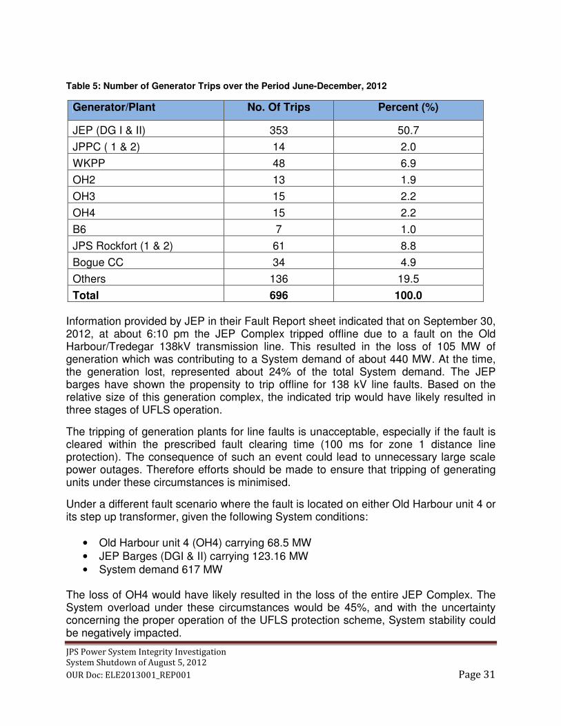
JPS Power System Integrity Investigation
System Shutdown of August 5, 2012
OUR Doc: ELE2013001_REP001 Page 31
Table 5: Number of Generator Trips over the Period June-December, 2012
Generator/Plant No. Of Trips Percent (%)
JEP (DG I & II) 353 50.7
JPPC ( 1 & 2) 14 2.0
WKPP 48 6.9
OH2 13 1.9
OH3 15 2.2
OH4 15 2.2
B6 7 1.0
JPS Rockfort (1 & 2) 61 8.8
Bogue CC 34 4.9
Others 136 19.5
Total 696 100.0 Information provided by JEP in their Fault Report sheet indicated that on September 30, 2012, at about 6:10 pm the JEP Complex tripped offline due to a fault on the Old Harbour/Tredegar 138kV transmission line. This resulted in the loss of 105 MW of generation which was contributing to a System demand of about 440 MW. At the time, the generation lost, represented about 24% of the total System demand. The JEP barges have shown the propensity to trip offline for 138 kV line faults. Based on the relative size of this generation complex, the indicated trip would have likely resulted in three stages of UFLS operation.
The tripping of generation plants for line faults is unacceptable, especially if the fault is cleared within the prescribed fault clearing time (100 ms for zone 1 distance line protection). The consequence of such an event could lead to unnecessary large scale power outages. Therefore efforts should be made to ensure that tripping of generating units under these circumstances is minimised.
Under a different fault scenario where the fault is located on either Old Harbour unit 4 or its step up transformer, given the following System conditions:
• Old Harbour unit 4 (OH4) carrying 68.5 MW
• JEP Barges (DGI & II) carrying 123.16 MW
• System demand 617 MW The loss of OH4 would have likely resulted in the loss of the entire JEP Complex. The System overload under these circumstances would be 45%, and with the uncertainty concerning the proper operation of the UFLS protection scheme, System stability could be negatively impacted.

JPS Power System Integrity Investigation
System Shutdown of August 5, 2012
OUR Doc: ELE2013001_REP001 Page 32
Clearly there is a fundamental issue with the ride-through capability of the medium speed diesel generators. Analysis undertaken in this and previous Enquiries corroborates the view that low voltage affecting the auxiliary equipment busbars is the main factor impacting the acceptable ride-through capabilities. This is unacceptable under North American Electric Reliability Corporation (NERC) generator protection guidelines, which recommend that generating units should not be tripped by undervoltage relaying, in accordance with IEEE standard C37.102 “IEEE Guide for AC Generator Protection”.
The appropriate response is to provide an alarm for low voltage conditions; if undervoltage tripping is provided, the set-points must be coordinated with external protection so that the generator is not taken off line for external System faults.
5.3 Under-Frequency Load Shedding The UFLS scheme is also a factor in maintaining a stable System. The situations described in Section 5.2 could have resulted in a disaster if the UFLS was not designed to allow the System to respond to the indicated level of over load.
Table 6 contains information obtained from JPS for the period June 24 - December 11, 2012 regarding the tripping of generating units/plants and the resulting UFLS operation.

JPS Power System Integrity Investigation
System Shutdown of August 5, 2012
OUR Doc: ELE2013001_REP001 Page 33
Table 6: The Effect of Generation Outage on UFLS and Online Reserves, June – December, 2012
No. Date Time Station Units
Tripped
Condition Prior to Outage UFLS
Stages
Remarks
Unit
Capacity
(MW)
Dispatch
Level
(MW)
System
Demand
(MW)
Online
Reserve (MW)
1 Jun-24 8:30 pm Bogue GT9 20.0 10.0 576.4 15.0 0
2 Jun-30 3:42 am OH JEP,
DG9 16.73 16.73 449.5 21.5 0
3 Jul-7 9:42 pm Bogue GT13 38.0 30.0 465.2 47.8 0, 1
4 Jul-7 3:38 pm Bogue GT13 38.0 26.7 492.4 43.7 0
5 Jul-7 5:25 pm Bogue GT3 21.5 17.0 481.6 54.9 0
6 Aug-8 6:59 pm Bogue GT12 38.0 36.0 552.3 105.9 0 Large online reserve
7 Aug-27 8:25 am OH OH4 68.5 45.7 472.7 85.2 0 Large online reserve
8 Aug-30 4:12 am OH OH4 68.5 43.4 422.9 87.8 0 Large online reserve
9 Aug-30 2:19 pm OH OH4 68.5 57.0 589.3 39.3 0, 1
10 Sep-26 4:02 am Hunts Bay B6 68.5 40.0 396.0 86.5 0, 1 Large online reserve
11 Sep-27 10:48 pm Bogue GT13 38.0 38.0 486.7 83.5 0 Large online reserve
12 Sep-30 4:55 pm Bogue GT12 38.0 36.0 435.3 51.7 0
13 Sep-30 5:55 pm Bogue GT7 14.0 10.7 440.0 30.6 0
14 Sep-30 6:10 pm OH JEP 124.0 105.0 440.0 Source: JEP
15 Oct-8 2:25 pm OH OH4 68.5 58.1 568.3 36.2 0, 1
16 Nov-4 8:36 am OH OH3 65.0 46.1 479.1 52.7 0, 1
17 Nov-7 2:07 am Hunts Bay B6 68.5 48.9 434.4 72.0 0, 1
18 Nov-16 4:11 pm Hunts Bay WKKP 65.5 66.4 520.5 52.6 0, 1
19 Nov-17 11:56 am OH JEP DG9 16.73 16.73 474.5 33.0 0, 1
20 Dec-17 9:17 am OH OH4 68.5 50.0 529.5 34.5 0, 1
As shown in Table 6 on a number of occasions the amount of MW lost due to generator trips is less than the planned spinning reserve, however UFLS operation still occurred. This indicates that although JPS employs a minimum of 30MW spinning reserve to reduce the extent of the UFLS, the spinning reserve regime is largely ineffective in containing System outages within the specified limit. This apparent dysfunction could negatively impact System security, stability and reliability.
5.4 Voltage Load Shedding The OUR Terms of Reference required the Committee to examine the applicability of the installation of Under Voltage Load Shedding (UVLS) protection to complement the UFLS scheme. The principle is that the protection scheme would shed load based on the level of detected voltages on critical busbars, similar to the UFLS scheme.
Research has indicated that such schemes are applied only in situations where a response delay is tolerable in the range of 1-10 seconds. Therefore, given that the Critical Fault Clearing Time (CFCT) at critical substations on the JPS 138kV network is of the order of 400 ms or less, the Committee is of the opinion that such a scheme would not be applicable.

JPS Power System Integrity Investigation
System Shutdown of August 5, 2012
OUR Doc: ELE2013001_REP001 Page 34
5.5 Grid Protection Philosophy and Maintenance The Committee has reviewed the general System protection philosophy which governs the basis of JPS’ installation of protective relays at generating stations and also at substations for busbars, transformers and transmission line protection. The Committee finds the systems currently in place to be generally adequate and meets international standards for reliable utility operation.
There are however, some issues and deficiencies which are unique to particular locations i.e. Duhaney substation which have been addressed elsewhere in this report.
The Committee feels that concerning the documented practice used as the reference and currently utilised by JPS for the test and routine maintenance of relays and control devices, the correct principle of cycle checks are adequate. Nevertheless, it is recognised that the human factor plays an important role in the effectiveness of maintenance, together with the dedication to detail and a process of rigid management follow up on defects is an issue of considerable concern.
Indeed, recent System shutdowns have highlighted this problem and JPS needs to urgently remedy the human factor in order to prevent a repeat occurrence.
5.6 Duhaney Substation The Duhaney 138/69kV substation is a major weak link in the transmission grid integrity as it serves as the only link between generators in the Corporate Area with the Old Harbour plants and Bogue located on the North West coast of the island. Any failure on either the 138kV or in particular the 69kV is likely to precipitate an island-wide System shutdown. Accordingly, the Committee has focused attention on and carefully analysed this particular facility and makes the following points and recommendations.

JPS Power System Integrity Investigation
System Shutdown of August 5, 2012
OUR Doc: ELE2013001_REP001 Page 35
Figure 12: One Line Diagram of Duhaney substation
A single line diagram of Duhaney substation is shown in Figure 12.
The protective relaying system for the Duhaney substation needs a complete review to remedy the weaknesses of the 69kV radial lines, 69kV busbars and 138/69kV transformer backup protection schemes. These measures include:
• The installation of new relays or re-setting of existing inverse–time overcurrent relays to instantaneous operation on the Naggo Head and Constant Spring 69kV radial lines, to facilitate immediate isolation of line faults.
The installation of overcurrent relays on the 69kV bus-tie breaker to facilitate
early separation of Bus #1 and Bus #2 in the event of a sustained fault on either
side.

JPS Power System Integrity Investigation
System Shutdown of August 5, 2012
OUR Doc: ELE2013001_REP001 Page 36
• The installation of backup inverse–time overcurrent relays on all three (3)
138/69kV transformers to sever and isolate the 138kV system from any faults
occurring on the 69kV busbars. Since relaying on the 138kV side of Duhaney
and remote relays at Tredegar and Old Harbour is unable to clear even a
sustained 3-phase fault on the 69kV busbars or attached lines, timed overcurrent
relays must be set to promptly carry out the necessary separation in order to
avoid a System collapse.
• The separation of operations of the 81 under-frequency relay component from
the 59/81 composite relay.
The issue of a recommendation from a previous Enquiry for installation of a dual station battery given the substation’s importance in providing the only link between Old Harbour and Hunts Bay power stations has not been addressed. If a single cell, of the many existing series connected nickel–cadmium cells comprising the 125V DC battery, was to fail, all of the control systems, protective relays, alerts and other devices depending on a reliable power source would be affected. International best practices would suggest as well that all primary, secondary and backup relaying be appropriately split between the batteries to reduce the risk of failure. Nevertheless, the Committee is of the view that an independent evaluation should be carried out to justify the need for dual batteries at critical locations.
The 69kV single busbar arrangement at the substation poses a significant risk to System security and requires some form of upgrading in order to limit the effects of a fault impacting the busbar. A breaker-and-half configuration would be ideal, however space at the location would appear to be limited. Therefore it is suggested that JPS examine the possibility of installing a 69kV ring bus which would add some level of security to crucial fault clearances.
Finally, it is suggested as an additional measure that JPS consider the possibility of down grading Duhaney substation to a two (2) 138/69kV transformer facility. This could be achieved by transferring one of the existing 80/100MVA transformers to the Hunts Bay B switchyard and possibly upgrading one of the existing 69kV lines to 138kV for tie back to Duhaney substation. Options include re-routing the Old Harbour 138kV line to Duhaney to directly tie into Hunts Bay.
This action would achieve both a reduced reliance on the Duhaney substation (which could be completely destroyed, including the relay building if one of the existing 80/100MVA transformers were to go up in flames) and establish a strong transmission tie linking the Old Harbour power stations to the considerable generating pool now existing at Hunts Bay/Rockfort.

JPS Power System Integrity Investigation
System Shutdown of August 5, 2012
OUR Doc: ELE2013001_REP001 Page 37
5.7 Station and Communication Batteries
The observation is made in connection with all key substations and power station switchyards that the availability of both the station battery which provides DC supply for protection and control circuits, as well as the communication battery which provides a similar function with regard to crucial data, control and monitoring to facilitate operation of the grid, is extremely critical.
A recommendation was made in the last Enquiry for JPS to “Evaluate the provision of a duplicate battery at critical 138kV substations,” which was not undertaken. Therefore, the Committee is of the view that a study should be carried out by independent evaluators as to the need for duplicate batteries for station and/or communication DC supplies at key grid facilities at both 69kV and 138kV voltage levels.
Such an evaluation should include the risk of failure of either one of the aforementioned batteries at these locations and the consequential threat to System security. The study should explore the need for stand-by generation, photovoltaic installations and any other feasible options available.
As cost will be a major concern, the indicative expenditure to undertake the options which have been considered by the evaluators and recommended for implementation should be provided in the study.
5.8 Grid Strengthening and Upgrading
The existing transmission connections between the main power stations at Hunts Bay, Old Harbour and Bogue are weak. While customer loads have doubled and substantial new generation added there has not been any significant upgrading of the main 138kV transmission network since that undertaken in 1983 -1986, almost thirty (30) years ago.
A break-up of the System leaving the rural infrastructure on a relatively long 138kV link to Bogue will inevitably result in load swings and frequency distortions which will cause lack of proper protection relay co-ordination and consequent malfunctioning of the primary relaying system. This situation will be made worse with the proposed base load generation exceeding 300MW from whatever fuel source. Therefore special attention is required to ensure that adequate transmission export capacity is in place to accommodate the expected new generation.
In addition to the above, the current intention to introduce “wheeling” where transmission system reliability, availability and correct voltage levels are important parameters for success, demands that early action be taken to improve grid integrity. Therefore there is a need for JPS to conduct planning studies for re-enforcement of the grid, in particular the138kV system. In respect of the recent history of some four (4)

JPS Power System Integrity Investigation
System Shutdown of August 5, 2012
OUR Doc: ELE2013001_REP001 Page 38
System shutdowns, if robust and direct alternative routes were available for MW and MVAR transfer between Old Harbour and Hunts Bay, as well as Old Harbour and Bogue power stations, the outcome would have been different.
5.9 Rural Grid Operating Mode The rural grid covering the Old Harbour to Bogue transmission network is currently operated with many 69kV loop circuits closed in parallel with the 138kV main bulk power transmission lines. While this approach ensures some form of security to the grid, the set up however, presents great problems in coordinating the proper function of primary and backup protection relays located on the 69kV loop circuits.
In instances of major System disturbances or grid separation, power swings and frequency distortions complicate the issue leading to trip-outs which may otherwise have been averted. Accordingly, the suggestion is made for JPS to further study the matter of opening some of the 69kV loops at select locations between the 138/69kV transformation points, preferably at points where there are minimum flows of MW and MVAR.
The effect would be to create radial 69kV lines, in respect of which the protection system would be very simple and reliable comprising possibly of instantaneous overcurrent relays for backup. On the radial lines there would also be containment of the extension of an outage from a fault. Zig-zag grounding transformers are already in place at these transformation points to serve as effective System grounds in the event of faults on the radials.
A future goal would be a requirement for a sturdy looped 138kV transmission system and operation of the radials which could be effected simply by opening 69kV breakers at selected points. The Corporate Area Zone 69kV existing loop operation would need to be continued unless or until a fundamental decision is made to upgrade the system in part or in whole to 138kV.
5.10 Corporate Area 69kV System Grounding JPS has indicated that the Single–Line-to-Ground (SLG) and Line-to-Line (LL) short circuit levels at the following busbar locations in the Corporate Area are as follows: Duhaney 69kV Duhaney 138kV Hunts Bay 69kV SLG – 1,171 MVA SLG – 1,876 MVA SLG – 1,776 MVA LL – 1,273 MVA LL – 1,383 MVA LL – 1,314 MVA

JPS Power System Integrity Investigation
System Shutdown of August 5, 2012
OUR Doc: ELE2013001_REP001 Page 39
At Hunts Bay where much of the generation is concentrated between the JPS B6, Gas Turbines and WKPP diesel units, the SLG fault level is considerably higher (35%) than the comparable LL fault level.
A request was made for information on the specific generator step-up transformers located in the Corporate Area Zone, which have the star neutral point solidly grounded. Based on the information made available and the SLG fault levels it is apparent that all such transformers are solidly grounded. See Appendix 11
The Committee suggests that JPS review this situation and take steps to un-ground some of the less important generator step up transformers in order to reduce the SLG levels, given that the Critical Fault Clearing Time will be negatively impacted by the higher SLG fault MVA.
The un-grounded star points could be connected to ground via a station class lightning arrestor sized to protect the neutral point from undue voltage up-lift during fault conditions. A by-pass switch installed across the lightning arrestor could facilitate direct grounding as needed.
5.11 System Control and SCADA Operations
It is noted that the restoration time for customer supplies following the System shutdown on August 5, 2012 was generally in-line with prior instances of total System collapse.
This observation is made given that the typical time taken for restoration is about 7 hours, except that in this case a number of unexpected events took place; black start issues at some power stations, the inadvertent re-closing of the Naggo Head line onto the fault, failure of synchronizing facilities at Bogue, as well as the time taken to physically repair the damaged pole#1 on the Naggo Head line.
The Company’s restoration policy and procedure document was examined by the Committee and the strategies specified for promptly restoring service to customers appear to be well considered, detailed and adequate for the purpose. We note however, a need for the System Control operators to be exposed to continuing training and exposure to the restoration techniques, given the need for speed while taking care in regard to safety and other relevant factors.
It has been indicated elsewhere in this report that a management method to follow up on the repair of dysfunctional critical items of grid equipment and System defects in an effective manner is greatly needed. To avoid items from falling ”through the cracks” the suggestion is made for System Control to log and date all such items and remit the information on a daily basis to the responsible maintenance management personnel. No item would be removed from the log unless verified by a competent senior person.

JPS Power System Integrity Investigation
System Shutdown of August 5, 2012
OUR Doc: ELE2013001_REP001 Page 40
In some instances of major System outages, there may be a requirement for a full analysis of the event to be undertaken by competent technical personnel prior to the restoration exercise. This clearly applies in complex situations where the originating cause of a trip-out is not obvious.
In regard to the tools available to the System Control operators, note is taken of the use of up-to-date computerized control equipment with state of the art applications. As such, the on-going training of key personnel to maximize the utilization of the Monarch EMS/SCADA system is recommended.
As well, the on-going maintenance of the data and communication systems network, RTUs, Digital Fault Recorders and Sequence of Events Recorders is of equal importance to the preservation of grid integrity.
5.12 Generation and Transmission Codes The Committee has examined the current draft of the Generation Code which is not yet in complete use by the main stakeholders involved in power generation i.e. JPS and the IPPs. A perusal of the document indicates that it is well structured, clearly sets out the applicable policy and practices for operation of generating units on the System and appears to address the main issues of concern or likely to arise between the Grid Operator JPS and the IPPs.
However, the following observations and suggestions are made.
While Section 6 of the Generation Code does provide for routine tests of generators, It is nevertheless recommended that all generator units above 5MW gross capacity operating on-line be subject to mandatory specified tests every five (5) years, which should meet the international standards for such testing, including;
• Verification of Real Power Capability.
• Verification of Reactive Power Capability.
• Verification & Modelling of Generator Excitation Systems & Voltage Controls.
• Coordination of Generator Voltage Regulator Controls with Unit Capabilities and Protection.
• Generator Performance During Frequency and Voltage Excursions.
Such tests should also be carried out routinely as part of re-commissioning exercises if major changes or upgrading is made to any generator. The tests should be geared among other objectives, to provide accurate machine parameters and characteristics to facilitate the proper modelling and the conduct of System studies.

JPS Power System Integrity Investigation
System Shutdown of August 5, 2012
OUR Doc: ELE2013001_REP001 Page 41
It is noted that no clear policy or provision is made in the Generation Code to specifically cover the dispatch of MVARs by IPPs. While it is appreciated that the respective Power Purchase Agreements (PPAs) may make some reference to this item, the matter of the proper maintenance of adequate busbar voltages and by extension that provided to customers is of paramount importance. Proper MVAR dispatch in some instances of System disturbances may well be a key factor to System stability. Therefore, the Committee recommends that a section be added to the Generation Code to clearly address this aspect of generation dispatch.
It is recommended that consideration be given to the development of a separate “Generation Inter-connection Code” (components of which are already in use) which does not form a part of the current Generation Code, in order to better focus on the issues inherent with the inter-tie arrangement between JPS and a current or future IPP or IPP/customer.
The Generation Code is a very important element in ensuring that proper and correct procedures are followed in the generation sector and therefore, should be enacted as soon as possible.
The Committee notes that a Transmission Code which similarly sets out the principles and practices for JPS operations covering System planning, engineering design, operations and maintenance for the transmission system is not yet completed. Given its vital importance to guiding all key operations relevant to grid integrity, the finalization of this document also needs to be expedited and promptly implemented.
Recommendations for the formation of a Grid Reliability Committee have been made under Section 8.3. The undertaking of the obligations of the various parties under the Generation Code and other relevant Codes will be enhanced and harmonized by the functioning of the Grid Reliability Committee, but care should be taken not to compromise the functions of the Generation Code Review Panel.

JPS Power System Integrity Investigation
System Shutdown of August 5, 2012
OUR Doc: ELE2013001_REP001 Page 42
6 COMPLIANCE WITH PORT RECOMMENDATIONS
A comprehensive report on the JPS compliance with the overseas Consultant Gowlings Consulting Incorporated & Rusnov Associates Limited - Power Outage Review Team (PORT) recommendations concerning the JPS System shutdown of July 15, 2006, is attached at Appendix 9.
In general, the many items comprising the recommendations which were categorised and coded for priority attention have been complied with in part or in whole.
• JPS has indicated that the “Computerised Maintenance Management System (COMMS) implemented to create defects and maintenance job orders, was put in effect in 2010”. Also that “Daily System defects are circulated via email to relevant operations personnel in substation maintenance and Communications departments”.
However, it is clear from the recent episode where a crucial protection relay was not repaired or replaced for some 4 months at Duhaney substation, that the intent of this system is not being achieved. A recommendation is made elsewhere in this report for the System Control operators to undertake logging of all key system defects as a parallel measure.
• The ten (10) substations reported as not having SCADA visibility need to be put on the system as soon as possible. Also, the missing alternative paths for the communication network including planned fibre and microwave links, require attention.
• The matter of the availability of “Black Start” facilities when required still appears to be an issue. Measures to remedy this problem are comprehensively and adequately covered in the Generation Code which requires enactment at an early date.
• The recommended training of System operators and other key operations personnel still appears to require further attention from JPS management, as current efforts seem to be in abeyance.
It should be noted that many of the earlier un-completed PORT recommendations have since been carried forward and formed a part of the enquiry recommendations for subsequent System shutdowns occurring on July 3, 2007 and January 9, 2008. Refer to Section 7 – Compliance with 2008 OUR Enquiry Recommendations.

JPS Power System Integrity Investigation
System Shutdown of August 5, 2012
OUR Doc: ELE2013001_REP001 Page 43
7 COMPLIANCE WITH 2008 RECOMMENDATIONS JPS has provided a detailed report on the Company’s compliance with the recommendations arising from the OUR enquiry into the January 9, 2008 Island-wide System shutdown. The report is attached at Appendix 10.
A perusal of the report along with follow–up clarifications sought from JPS by the Committee indicates that the Company has generally responded to the recommendations and implemented the majority of items flagged for action.
However, the following items remain an issue;
• Re-commission all substation alarms – While this exercise was reported as completed in October 2008, JPS is to be reminded that maintenance checks should be an on-going activity and if a program is not now in place to do this, such a system should be developed and implemented.
• Install fault recording equipment at the JPPC Rockfort plant - Time synchronizing of the installed SOE equipment at JPPC needs to be implemented as soon as possible.
• Evaluate the provision of a duplicate battery at critical 138kV substations – This recommendation was not complied with by JPS. However, the matter of duplicate batteries at critical Grid facilities is addressed in Section 5.7 – Station and Communication Batteries.
• Take steps to ensure major generating units can ride-through System upsets – boiler automatic and manual controls, auxiliary systems, voltage regulators; include a steam dump valve to relieve drum pressure excursions due to load rejections – The inability of generators across the System to “ride-through” major System disturbances remains a major issue and a main contributor to System collapse incidents. A specific recommendation for an approach to deal with this vital issue is set out in Section 5.2 – Generator Ride-Through Capabilities.
• Perform a work-study analysis to establish appropriate staffing levels for the Protection and Control group – This issue is apparently still a problem and JPS needs to accord some priority to the personnel aspect in order to ensure that among other goals, proper and effective maintenance of the technically complicated gird infrastructure takes place.

JPS Power System Integrity Investigation
System Shutdown of August 5, 2012
OUR Doc: ELE2013001_REP001 Page 44
8 OUR MONITORING OF JPS AND IPPs Regulatory oversight of reliability in Power Systems can be detailed, extensive and comprehensive. Nonetheless, effective oversight can encourage compliance and appropriate behaviour by System participants. The utility must ensure that there is adequate generation and transmission resources to meet standards that assure a reliable electricity supply to customers. At the same time, entities that use the transmission system must adhere to the established codes and standards for the reliable operation of the power grid.
The regulator must vigorously oversee compliance with the applicable codes and standards, and violations should be subject to penalties.
In the Jamaican electricity market, the OUR has oversight responsibility for reliability, which encompasses the entire interconnected Power System.
The OUR, pursuant to its statutory function, is obliged to set out the regulatory monitoring framework, which will establish the rules for ensuring the appropriate levels of System reliability and security and the monitoring approach for achieving compliance by System participants. This applies to:
• JPS in its capacity as Grid Operator and also Owner of Generation Facilities; and
• Independent Power Producers (IPPs)
8.1 Monitoring of JPS
Licence requirements:
The Amended and Restated All-Island Electric Licence 2011 (“the Licence”) issued to JPS provides a framework for the efficient planning and reliable operation of the country’s electricity System as set out below.
Condition 2, paragraph 3 of the Licence requires the Licensee (JPS) to provide an adequate, safe and efficient service based on modern standards.
Condition 22, requires the Licensee to comply with a Generation Code as approved by the Office, consistent with internationally accepted technical standards and best practice and which is in accordance with prudent utility practice:
(a) Covering all material technical aspects relating to connections to and the
operation and use of the System (and insofar as they affect the system, the
operation of electric lines and electrical plant connected to the system);

JPS Power System Integrity Investigation
System Shutdown of August 5, 2012
OUR Doc: ELE2013001_REP001 Page 45
(b) Setting out the rules and procedures which govern the despatch and scheduling
of generator maintenance;
(c) Setting out the rules and procedures which provide for the safe and secure
operation of the System; and
(d) Designed to ensure:
i) The development, maintenance and operation of an efficient, co-ordinated
and economical system for the generation and transmission of electricity;
and
ii) The promotion of security and efficiency of the System as a whole.
Condition 24, paragraph 1, requires the Licensee to follow prudent utility practices, detailed technical design standards relating to the Transmission System and the Distribution System to cover areas such as technical criteria and conditions for connection of customers; reliability targets for major sub-systems of the Transmission System; the configuration and distribution of sub-stations and transformers and the design standards for the Transmission and Distribution Systems.
Condition 34, requires the Licensee to establish, implement and comply with a Transmission and Distribution Code, consistent with internationally accepted technical standards and which is in accordance with prudent utility practice.
In view of the responsibility of the OUR to ensure the availability, security and reliability of electricity supply to customers, it is imperative that continuous monitoring of JPS’ System operations is carried out by adopting the following:
• Ensuring that the codes and standards mentioned above are established and
implemented as soon as possible;
• Setting and ensuring reliability benchmarks and Key Performance Indicators
(KPIs) for the Generation and Transmission System;
• Ensuring that JPS complies with all the established rules, practices, policies and
procedures, codes and standards necessary for the safe, secure and reliable
operation of the System;
• Investigate the conduct of JPS in the operation and maintenance of the
transmission system and generation plants;
• Requiring periodic reliability performance reporting on the generation and
transmission systems;

JPS Power System Integrity Investigation
System Shutdown of August 5, 2012
OUR Doc: ELE2013001_REP001 Page 46
• Establishing, monitoring and enforcing inspection and maintenance standards for
generation and transmission apparatus;
• Reviewing customer service reliability complaints to ascertain cause and effects,
and possible deficiencies in the network;
• Investigating the conduct of the Grid Operator in major System events; and
• Investigating complaints against the Grid Operator by other market participants.
In carrying out the monitoring functions it is recommended that the activities be carried out utilizing a number of complementary mechanisms.
1. Routine auditing carried out by OUR or agents appointed for that purpose.
2. The submission of periodic reports by JPS in connection with specific areas
indicated by the OUR where it has been determined that correct operation and/or
maintenance is critical to grid reliability.
3. The conduct of special Enquiries or investigations by the OUR or experienced
and qualified professionals.
Some of the component facilities which would clearly require attention and be a focus of monitoring would include:
• Transmission lines
• Substations, including protective relaying
• Generators and auxiliary systems at power stations
• Communications network
• SCADA/EMS
Implementation of the above, at the earliest opportunity, is recommended.
8.2 Monitoring of IPPs
Subject to conditions in their respective Licences, IPPs are required to comply with the Generation Code, their respective PPAs and other applicable codes and standards.
This framework forms the core for monitoring the reliability performance of IPPs interconnected to the System.

JPS Power System Integrity Investigation
System Shutdown of August 5, 2012
OUR Doc: ELE2013001_REP001 Page 47
In the process of monitoring IPPs, the OUR should seek to:
• Ensure that IPPs comply with all the established rules, practices, procedures, codes and standards necessary for the safe, secure and reliable operation of the Power System;
• Ensure periodic reliability performance reports are submitted in a timely manner;
• Establish, monitor and enforce inspection and maintenance standards;
• Investigate the conduct of IPPs in major System events.
In carrying out the monitoring functions it is recommended that the activities be carried out utilizing a number of complementary mechanisms.
1. Routine auditing carried out by OUR or agents appointed for that purpose.
2. The submission of periodic reports by IPPs in connection with specific areas
indicated by the OUR where it has been determined that correct operation and/or
maintenance is critical to grid reliability.
3. The conduct of special Enquiries or investigations by the OUR or experienced
and qualified professionals.
Some of the component facilities which would clearly require attention and be a focus of monitoring would include:
• Generators and auxiliary systems at power stations
• Switchyard
• Sequence of Events Recorders and other relevant monitoring equipment
Implementation of an effective monitoring system, as outlined above, will serve to focus attention on the weaknesses and deficiencies of the System, the correction of which will significantly enhance the reliability of the System.
8.3 Establishment of Grid Reliability Committee (GRC) In light of the frequency of total System shutdown events in the Jamaican Power System, the OUR needs to consider the establishment of an on-going Grid Reliability Committee (GRC) as an added means of addressing issues impacting the reliability and security of the Power System. The group would meet regularly to identify items which

JPS Power System Integrity Investigation
System Shutdown of August 5, 2012
OUR Doc: ELE2013001_REP001 Page 48
currently threaten or could threaten grid integrity and ensure expediting of agreed remedies. The OUR should chair the GRC to include the major stake holders i.e. JPS, the major IPPs and any other participant considered appropriate. The GRC’s major responsibilities would include:
• Working with all stakeholders to assist in the development of codes and standards necessary for the reliable operation of the Power System;
• Assisting with the monitoring of compliance with those standards;
• Assessing Generation and Transmission resource adequacy;
• Providing educational resources to assist Power System participants in improving their understanding of the System’s topology and operation; and
• Assisting in the investigation and analysis of the causes of significant Power System disturbances in order to help prevent future events.
The OUR should ensure as convener of the GRC, that there is no conflict of interest or over-ride of the responsibilities of the Generation Code Review Panel established under the Generation Code. The OUR should ensure that similar consideration be given when the Transmission Code is enacted.

JPS Power System Integrity Investigation
System Shutdown of August 5, 2012
OUR Doc: ELE2013001_REP001 Page 49
9 SANCTIONS FOR BREACHES
Very serious breaches under the OUR Act or a situation of on-going non-compliance with the Directives of the OUR which has oversight responsibility for the reliable and economic delivery of services from utilities in connection with operational issues, requires strong action on the part of the OUR to effect compliance.
Such action could entail the application of sanctions against the specific utility or regulated entity in instances when particular situations occur. However, the action would necessarily have to be legally applicable either under the general provisions of the OUR Act or specifically under an applicable Law or Statute which governs the operations of the regulated entity.
The Telecommunications Act which is of modern vintage provides for such sanctions to be imposed by the OUR. However, it is not expected that the Electric Lighting Act which was enacted many years ago will any time soon be amended or reframed to cover the issue of sanctions for breaches. Therefore for the foreseeable future, reliance would have to be placed on amendments to the provisions of the existing OUR Act to deal with the matter of sanctions in the Electricity Sector.
In the case of electric Power System, there are instances such as System shutdowns which affect the entire country resulting in significant financial and economic impact to the various rate categories including industrial and residential customers. Consequently, if there are situations where there has been a clear breach of set standards, practices or codes or where such breach continues to be in existence despite the reasonable efforts of the OUR then sanctions should be applied.
However, the contemplated action should not itself be a breach of any licence conditions or impose undue hardship of the licensee.
The OUR Act as currently exists does not now provide for a situation as set out above. Section 9 (2) of the OUR Act in general terms only mandates a penalty against the licensee in the event that a regulated entity is not fulfilling its obligation under its licence conditions or enabling instrument. In the case of a continuing breach, the provisions of the OUR Act allow for the prosecution of the licensee before a Resident Magistrate wherein a fine may be imposed.
Clearly, in order to effect sanctions as being envisaged it would be necessary to carry out inter-alia, an amendment to the OUR Act which clearly sets out the conditions under which such sanctions may be applied and by whom. Since the OUR would appear to be exercising the powers of “judge and jury” if given the authority to unilaterally impose sanctions without constraints it would be necessary that certain specified pre-conditions be met.

JPS Power System Integrity Investigation
System Shutdown of August 5, 2012
OUR Doc: ELE2013001_REP001 Page 50
It is suggested that these would have to include:
• Transparency in respect of any investigation carried out by the OUR whether
conducted internally or by contracted parties.
• The facilitation of the licensee to be present, be represented or be put into a
position of being able to respond verbally or in writing to any alleged breach of
the amended OUR Act.
• That limitations be placed on the levels of sanctions that can be applied in
particular situations of a breach.
• That the monetary value of the sanctions should be interpreted as a penalty to
licensee for the breach and not as compensation to any customer or customers
of the licensee who may have suffered financially from the breach.
It is recommended that since any amendment to the OUR Act would necessarily apply across the board to all regulated utilities and entities except where otherwise prescribed by an applicable sector specific Law, it would be prudent that the effect of any amendment be examined scrupulously by experienced legal persons.
While it may appear practical and reasonable to set the limitation of a monetary sanction for a breach as a percentage of the Net Income of the licensee, the complexity and subset of the licensee’s Net Income may be such that the sanction level which results may be an unreasonable amount for the breach. A similar situation may exist if the sanction is based on the asset base of a utility given the variation in investment value and size of the regulated entities and their mode of operation.
Therefore, it is recommended that a detailed study be made by knowledgeable legal minds and other relevant professionals in order to examine the many issues which could arise from the matters raised above, prior to any consideration of amending the OUR Act.

JPS Power System Integrity Investigation
System Shutdown of August 5, 2012
OUR Doc: ELE2013001_REP001 Page 51
10 RECOMMENDATIONS
The Committee has extensively reviewed the detailed submissions from JPS and IPPs, responses to specific questions raised, as well as other relevant documentation. The Committee made certain observations and arrived at a number of conclusions, the consequence of which it makes the following Recommendations.
10.1 Jamaica Public Service Company Ltd JPS should urgently carry out the Recommendations made in their report entitled “Technical Report Power System Shutdown - August 5, 2012” dated September 28, 2012 (see Appendix 1).
In addition, the specific recommendations of the Committee are as follows:
1) Urgently review the protective relaying configuration for Duhaney substation to remedy the weaknesses inherent in the protection schemes for the 69kV radial lines, 69kV busbar, 138/69kV transformers backup protection and the apparent malfunction of the Duhaney/New Twickenham transmission line protection.
2) Commission a study to be undertaken by independent evaluators on the necessity for the installation of a second station battery and/or communication battery at critical substation and power station switchyard locations island-wide.
3) Evaluate recommendations for down-grading the Duhaney substation given its present potential to seriously compromise the grid integrity and either cause or adversely contribute to a total Power System collapse.
4) Conduct planning studies to evaluate an apparent need to upgrade and strengthen the 138KV grid so that robust direct links are available to tie the main generating plants to each other for support island-wide and reduce the possibility of grid separation during major System disturbances.
5) Engage the services of experienced and qualified professionals to conduct a detailed assessment of the dire and unacceptable problem with “Ride-Through” tolerances of generators on the System, including low voltage protective schemes and settings; affecting in particular, the medium speed diesel generators and make specific recommendations to guarantee that the generators do not trip off spuriously and unnecessarily during major System disturbances, a copy of which should be made available to the OUR.

JPS Power System Integrity Investigation
System Shutdown of August 5, 2012
OUR Doc: ELE2013001_REP001 Page 52
6) Carry out a study to determine the cause of the transient rise in voltage in the Corporate Area following the grid separation resulting from the August 5, 2012 System shutdown which caused the tripping of WKPP diesel generators and undertake remedial actions.
7) Revise the current JPS System restoration manual to include analysis by competent technical personnel in situations where the initiating cause of an outage is not apparent, prior to restoration of the System.
8) Evaluate the recommendation to un-ground some of the generator step-up transformers located in the Corporate Area with the objective of reducing the 69kV single line to ground (S-L-G) fault levels.
9) Ensure that the maximum fault clearing time setting for primary and backup protection at all busbars deemed critical to System security does not exceed the Critical Fault Clearing Time (CFCT) for that busbar.
10) Implement a program of on-going tests and maintenance on all manual and automatic synchronizing equipment installed on the grid.
11) Review and remedy the current problem with “write-over” of data on critical protection relays.
12) Undertake discussions with manufacturers and conduct whatever research is necessary to understand the reasons for the non-operation of some of the Under-Frequency Load Shedding (UFLS) schemes, when the System is subjected to severe disturbances.
13) Comprehensively review the overall UFLS scheme, taking into consideration
the feeder/load characteristics for peak, partial peak and light load conditions.
14) Review the current policy and procedures covering the dispatch of MW and MVAR by the System Control operators to ensure that IPPs always operate under the dispatchers guide and in strict compliance with agreed practices.
15) Review the policy and procedures for dispatch of MVARs from generating units, the automatic/manual control of 69kV capacitor installations and the maintenance of correct voltages on 138kV and 69kV busbars island-wide undertaken by JPS System Control operators, particularly at light loads.
16) Develop an action plan and promptly effect in-service implementation of all Sequence of Events Recorders required to facilitate proper System operation.
17) Immediately implement time synchronizing of all GPS systems installed on the grid and at power stations, which was previously recommended and is long overdue.

JPS Power System Integrity Investigation
System Shutdown of August 5, 2012
OUR Doc: ELE2013001_REP001 Page 53
18) Ensure the repair, on-going maintenance and availability of all Digital Fault Recorders installed on the grid.
19) Ensure that full simulator training of System Control operators in System recovery techniques for partial or total System shutdown is undertaken and repeated at intervals.
20) Ensure that System Control Centre maintains an on-going log of crucial System defects which is copied to all responsible maintenance management personnel.
21) Examine options and implement physical changes to the existing JEP 138kV single tie-line interconnection to the JPS grid at Old Harbour which supports a total of 124MW of diesel generation, in order to provide a second 138kV link to the Old Harbour switchyard.
22) Implement a program wherein full load or partial load rejection tests, along with other required routine operational machine tests are performed periodically on all JPS and IPP generating units above 5MW capacity within a five (5) year time span.
23) Ensure that the parameters, particularly the inertia constants of the engine/generator sets of the IPPs and possibly JPS generator units used for planning and stability studies reflect the actual values of the machines.
24) Conduct a study to evaluate the impact of the multiple smaller capacity medium speed diesel generators versus the conventional steam/slow-speed diesel machines on System stability.
25) Complete the implementation of plans for full redundancy of alternate communication signal and data routing in the event of failure of the default path.
26) Review the possibility of circular power flows between Old Harbour, Tredegar, Duhaney and the New Twickenham 69kV substation.
27) Ensure that full SCADA visibility of monitored and controlled apparatus installed on the grid is a priority objective and that a near 100% up time is maintained.
28) Ensure that all plants equipped with “Black Start” facilities keep the start-up machines in good working order.
29) Ensure that the Generation Code which sets out the agreed policy and procedures for generating operations between JPS and the IPPs is complied with.

JPS Power System Integrity Investigation
System Shutdown of August 5, 2012
OUR Doc: ELE2013001_REP001 Page 54
30) Cooperate with the OUR to examine the appropriateness of developing a “Generation Inter-connection Code” in respect of which components are already in use, as a separate document from the Generation Code.
31) Complete the Transmission Code which is in the draft stage and implement promptly.
10.2 Independent Power Producers (IPPs) JEP, WKPP & JPPC
1) Ensure that all diesel generation plants equipped with Black Start facilities are kept in an “available on call” condition with the start-up machines in good working order.
2) Cooperate with JPS and its agents and consultants in the conduct of the assessment of issues related to the “Ride-Through” capabilities of its generators.
3) Support the implementation as required of all the provisions of the Generation Code.
4) JEP along with JPS examine options and implement physical changes to the existing JEP 138kV single tie-line to the JPS grid at Old Harbour which connects an aggregate of 124MW of installed diesel generation.
5) WKPP to carry out checks on relay configuration and settings to determine whether the protection scheme is operating correctly for low voltage conditions.
10.3 Office of Utilities Regulation (OUR)
1) Review and expand the present method of monitoring JPS and the IPPs, technical operations and maintenance, including follow-up on items crucial to System integrity arising from previous System shutdown Enquiries and investigations.
2) Employ third party consultants or other technical experts to conduct periodic audits into the technical functioning of aspects of the JPS and IPPs operations.
3) Convene and chair a “Grid Reliability Committee” to include the major stake holders i.e. JPS, the major IPPs and any other participant considered appropriate.

JPS Power System Integrity Investigation
System Shutdown of August 5, 2012
OUR Doc: ELE2013001_REP001 Page 55
4) Ensure through its regulatory oversight authority that the Generation Code which binds JPS and the IPPs to a common and agreed set of technical commitments and operating practices for generation, is enacted and its specific provisions observed by the parties.
5) In consultation with JPS, examine the appropriateness of developing a “Generation Inter-connection Code” in respect of which components are already in use, as a separate document from the Generation Code.
6) Ensure that early completion of work on the Transmission Code is undertaken by JPS.
7) Prepare a list of standard precursor actions which JPS and IPPs should take after a System incident in order to preserve the evidence as far as is possible.
8) Conduct studies to facilitate the development of an appropriate legal framework and mechanism for the imposition of sanctions by the OUR in the Electricity Sector
It is considered that given the need and urgency of implementing some of the recommendations indicated above, specific timelines should be set by the OUR. It is recommended that such timeframes be included as part of any future Directive sent to the relevant regulated entities.

JPS Power System Integrity Investigation
System Shutdown of August 5, 2012
OUR Doc: ELE2013001_REP001 Page 56
APPENDIX 1
EXECUTIVE SUMMARY
OF
JPS TECHNICAL REPORT
POWER SYSTEM SHUTDOWN – AUGUST 5, 2012

JPS Power System Integrity Investigation
System Shutdown of August 5, 2012
OUR Doc: ELE2013001_REP001 Page 57
EXECUTIVE SUMMARY
Event
On Sunday, August 5, 2012 at approximately 11:59 pm, the JPS power grid experienced a total system shutdown (collapse) initiated by a fault on woodpole # 1 on the Naggo's Head radial 69kV line located just outside the Duhaney substation. The fault was cleared by remote backup protection in 1.23s, with generator and transmission line trips occurring during and subsequent to the fault event and the creation of several -power islands during the cascade to shutdown. It was observed that at pole #1, a TDE pole, the pilot insulator was dislodged from the cross-arm and was resting on the brace of the lower cross-arm. Further inspection of the arm shows that the arm is an aged cross-arm that was burnt off, possibly caused by tracking due to contamination. The last Detail patrol done in March 2011 indicated that the cross-arms were in satisfactory condition at this location. Prior to the fault, the Naggo Head line distance protection trip circuit at Duhaney was disabled due to a malfunctioning Micom P441 distance relay, the back-up directional overcurrent protection was however, still in service. This caused the delayed fault clearance as the direction overcurrent protection operated on a time-inverse curve beyond the critical fault clearing time, a therefore the cascade to system collapse.
Historical Shutdown Performance The JPS power system has experienced five (5) all island system shutdowns since year 2000 that are summarised in the following table. An internal JPS team, the Office of Utilities Regulation (OUR) and an external Power Outage Review Team (PORT), comprehensively investigated the July 15th, 2006 event. Arising from these investigations several recommendations were made which are relevant to the investigation and review of this shutdown event on August 5, 2012.

JPS Power System Integrity Investigation
System Shutdown of August 5, 2012
OUR Doc: ELE2013001_REP001 Page 58
August 5, 2012 July 9, 2008 July 3, 2007 July 15, 2006 October 24, 2001 Feb. 27, 2000
Day and time Sun, 11:59pm Sat, 6:12pm Tue 5:11am Sat, 4:16pm Wed, 5:37pm Sun, 12:47pm Initiating Event Failed crossarm
at Loc #1 on Duh-Naggo Head 69kV line
Loc #18 Woodpole failure on Duh-Tred. 138kV line
Flashover on arrestor on OH2 GSU
Lightning 3-ph fault on Bogue-Duncans 138kV line
Manual 69kV switching onto 2-ph fault on 13.8kV
Fire protection malfunctioned, resulting in 3-ph fault on 138kV
System Load 398 MW 547 MW 445.3 465 MW 425 MW 326MW Spinning Reserve 50.1 MW 60.53 71.1 MW 30 MW 70MW 69MW Restoration 9.5 hours 4.15 hours 11.75 hours 8 hours 5.75 hours 3 hours Elapse time to Shutdown
>10s 8 s >10s >10s >10s >10s
System Defects Yes (suspected
defective primary distance relay disabled)
Yes (burnt breaker trip coil, dc breaker for breaker fail scheme “off”)
Yes (dislodged downdropper on 138kV switch)
Yes (open DC breaker, disabled primary protection, SCADA unavailability)
Yes (non-functioning HV cct breakers due to discharged batteries)
Yes (fire protection system)
SCC Aware of Defects
No No No (not relevant)
No (regarding DC breaker & protection)
No No (not relevant)
Malfunction of Line Protection
Yes Yes Yes Yes Yes No
Incorrect Gen Protectn
Yes No No Yes Yes Yes
Blackstart problems
Yes (JEP & JPPC)
Yes (JEP & JPPC)
No (but generators took a long time to come online after station energised e.g. JPPC, Rockfort, OH)
Yes Yes Yes
Prior System Condition Prior to the system event the island was experiencing inclement weather (rain, wind and lightning activities) associated with tropical storm Ernesto. The available generation capacity at 11:59pm was 580.53 MW. The online capacity was 448.3 MW serving a demand of 398.2 MW, with a spinning reserve of 50.1 MW. The Hunt’s Bay B6 unit was on forced maintenance; JPPC unit 1 was on forced restriction,

JPS Power System Integrity Investigation
System Shutdown of August 5, 2012
OUR Doc: ELE2013001_REP001 Page 59
while the JEP complex was restricted to 102.12 MW (DG#10 on planned outage); OH unit #2 on planned maintenance. Three (3) transmission lines were out of service due to faults which and the Maggotty line breaker at Spur Tree was out of service for repairs. Approximately 36,000 customers were out of service due to the outage of feeders on Annotto Bay, Highgate, Port Antonio, Greenwich Road and Tredegar feeders. Power flow along the bulk 138kV transmission lines were less than 50% of rated capacity in all cases and voltages across the network were within normal tolerances except within the Corporate Area. SCADA visibility of the 53 visible substations was 100% prior to the event. Event Analysis A fault on the Duhaney – Naggo Head 69 kV line would require the line primary distance and backup overcurrent protection schemes to activate to clear the fault. On August 5, 2012 at 11:59:16.721 when the fault developed on the Duhaney – Naggo Head line the primary distance relay trip circuit was disabled. It was revealed by JPS that during routine inspections on April 2, 2012 the relay was observed showing erroneous measurement data and the responsible engineer authorised the disabling of the trip circuit to prevent spurious operation and to allow for further evaluation of the relay. It was left unresolved and unattended for four (4) month period and the method of disabling prevented the generation of SCADA alarms. In the absence of the trip circuit for the primary distance protection the backup protection is required to trip the circuit breaker. By design, the directional overcurrent relays generally do not coordinate with distance relays and with the failure of the local distance relay trip function for the Naggo Head line, remote distance relays at Washington Boulevard, Port Authority, Hunts Bay and New Twickenham are required to operate to interrupt the fault. Remote zone 2 distance relay operations occurred at Washington Boulevard, Port Authority and Hunts Bay and isolate the fault from the Corporate Area generation within 523 ms. At this point the system is divided into two sub-systems, namely, the Corporate Area sub-system and the Rural Area sub-system. The fault was eventually cleared by the operation of the 69kV Naggo Head line breaker at Duhaney substation (8-610) subsequent to a trip signal from the backup protection overcurrent relay on the Duhaney-Naggo Head 69kV line. The rural area island continued to experience fault conditions, with multiple transmission line trips on primary distance Z1 ABC (Kendal- Duncans 138kV, Bellevue-Duncans 138kV, Ocho Rios-Roaring River 69kV, Bellevue-Lower White River 69kV, Lower White River-Ocho Rios 69kV, Duhaney-Tredegar 138kV, Monymusk 69kV breaker towards

JPS Power System Integrity Investigation
System Shutdown of August 5, 2012
OUR Doc: ELE2013001_REP001 Page 60
Parnassus) and generator trips (JEP Barge, Old Harbour #3) occurring up to the clearance of the fault at 1.23s after fault inception. These multiple transmission line trips created a further splintering of the main power island into several non-viable islands. This was caused by mal-operation of system protection relays on 138 kV and 69 kV transmission lines resulted in the tripping of several non-faulted lines and then creation of several generation islands on the grid of which none survived. The generating units at Old Harbour, that is JEP and OH3, as well as JPPC and Rockfort tripped before the fault was isolated from the system resulting in depressed system voltage as a consequence of the fault. This remaining generators trip offline during the spurious transmission trips creating unsustainable islands (load-generation balance) culminating in a total system shutdown.
System Restoration A total system shutdown was confirmed after the status of all generating plants was ascertained. Subsequent to this confirmation, restoration plans and activities at all locations were commenced. SCADA indication suggested that there was a major system disturbance at Duhaney on the 69kV bus as it had been isolated by remote and local breakers. This was a significant factor in this event and the relevant field personnel were dispatched to this location to conduct investigations. At 1:18am System Control was advised that the 69kV bus was checked and found with no fault, and protection relays reset. Black start instructions and switching operations commenced at 12:05 am. This represented the start of the restoration process. The decision was taken to create two (2) islands for the restoration process. JPPC and JEP reported problems with making black start facilities available and were not black-started. At Hunts Bay GT10 came online at 12:27 am with Hunts Bay feeders, while at Bogue, GT7 was brought online at 12:26 am with Bogue 410. After stability of the electrical islands was achieved, then a path was created using 138kV transmission lines to interconnect and synchronise the islands. The entire grid was fully energized at 9:23 am with the re-storation of Naggo Head substation and Naggo Head feeders by 9:26am. Customers served from Annotto Bay, Highgate and Port Antonio substation remained out of service due to faulted transmission lines serving those substations, as well as Michelton 110 that was also out on a feeder fault.

JPS Power System Integrity Investigation
System Shutdown of August 5, 2012
OUR Doc: ELE2013001_REP001 Page 61
The restoration process began at 12:05 am and ended at 9:26 am and therefore took 9 hours and 21 minutes.
Demand and Customer Restoration Profile
CONCLUSIONS
1. A permanent three-phase fault developed on the Duhaney to Naggo Head line at pole # 1 just outside of Duhaney substation. The fault was not cleared within the critical fault clearing time to prevent system instability. Therefore it precipitated a series of generators and transmission lines trips causing a system shutdown.
2. The delayed fault clearance was due to the prior disabling of the trip circuit for the primary distance protection of the Duhaney – Naggo Head 69kV line and the setting of the backup overcurrent relay outside the required critical fault clearing time at Duhaney 69kV bus.
3. The mal-operation of system protection relays on 138 kV and 69 kV transmission lines resulted in the tripping of several non-faulted lines and then creation of several generation islands on the grid of which none survived.
0% 0% 3%9%
20%25%32%
37%42%46%
70%79%82%83%86%88%88%88%88%92%92%
0%10%20%30%40%50%60%70%80%90%100%
0.0050.00
100.00150.00200.00250.00300.00350.00400.00450.00
12
:00
AM
12
:30
AM
1:0
0 A
M
1:3
0 A
M
2:0
0 A
M
2:3
0 A
M
3:0
0 A
M
3:3
0 A
M
4:0
0 A
M
4:3
0 A
M
5:0
0 A
M
5:3
0 A
M
6:0
0 A
M
6:3
0 A
M
7:0
0 A
M
7:3
0 A
M
8:0
0 A
M
8:3
0 A
M
9:0
0 A
M
9:3
0 A
M
10
:00
AM
% C
ust
om
er
Re
sto
red
MW
De
ma
nd
Time
System Restoration - August 6, 2012
Demand (MW) and Customer Restoration Profile
% of Total MW Demand

JPS Power System Integrity Investigation
System Shutdown of August 5, 2012
OUR Doc: ELE2013001_REP001 Page 62
4. The system experience a system split at Duhaney during the fault and the Corporate Area subsystem lasted for 7.58 seconds while the Rural Area sub-system lasted for 18.758 seconds before collapse due voltage violations.
5. Other islands were created in the Rural Area sub-system where the hydros at Lower White River and Upper White River were separated from those at Roaring River and Rio Bueno and they were in turn separated from the generators at Bogue and Maggotty.
6. Operation of the WKPP generators on constant power factor control contributed to the collapse of the Corporate Area sub-system.
7. The initial tripping of the first four units on JEP barge 1 was due to battery failure and consequent PLC mal-operation.
RECOMMENDATIONS
1. Review protection philosophy with regard to Radial Transmission lines to ensure the N-1 protection failure will not cause system instability.
2. Implement a “Systems Defects” management system to effectively manage the
reporting, assignment, corrections and notifications of status and progress to critical stakeholders (e.g. System Control)
3. Conduct re-training of Systems Operations personnel in the existing JPS policies
and procedures with regard to system changes and commissioning.
4. Review with the relay manufacturer the reasons for the mal-operation of the protection relays with “frequency tracking” and implement recommendations to mitigate against a recurrence.
5. Aggressively implement the recommendations from the review of the Protection
and Control (P&C) philosophy as was done by the P&C consultant.
6. Finalise and implement selected recommendation from the Siemens PTI Stability study to mitigate the adverse impact of stuck breaker conditions at Duhaney substation on system security
7. Conduct system security study focussed on reviewing islanding of the network
during major system disturbance to include recommendations for additional UFLS points and the distribution of these points on the JPS network.
8. Conduct review and provide recommendations on the required operations mode
of WKPP in the Corporate Area subsystem to support system security in

JPS Power System Integrity Investigation
System Shutdown of August 5, 2012
OUR Doc: ELE2013001_REP001 Page 63
particular when Hunts Bay B6 is out of service.
9. Fast Track the purchasing and installation of digital fault recorders on the network.
10. Fast Track time-synchronisation of devices on the network required for post-
system disturbance analysis. 11. Implement regular training and development “Power System Analysis”
workshops for improving system planning and protection capabilities in performing system analysis and studies utilising the simulation softwares PSS/E and CAPE.
12. Correct issues with black-start facilities at JEP and JPPC, which have failed in
previous system shutdowns.
13. Review all synchronizing facilities on the network for correct operation, and correct failed synchronizing facility at Bogue substation.
14. Conduct re-training of Systems Operators personnel in restoration strategies and
stress management techniques to ensure minimisation of network restoration times.
15. Ensure compliance with voltage management policies and criteria by System
Operators during system light load conditions.

JPS Power System Integrity Investigation
System Shutdown of August 5, 2012
OUR Doc: ELE2013001_REP001 Page 64
APPENDIX 2
JPS POWER SYSTEM INTEGRITY INVESTIGATION
TERMS OF REFERENCE

JPS Power System Integrity Investigation
System Shutdown of August 5, 2012
OUR Doc: ELE2013001_REP001 Page 65
Office of Utilities Regulation
JPS POWER SYSTEM INTEGRITY
INVESTIGATION
Terms of Reference

JPS Power System Integrity Investigation
System Shutdown of August 5, 2012
OUR Doc: ELE2013001_REP001 Page 66
September 2012
1. INTRODUCTION ......................................................................................................... 67
2. BACKGROOUND ........................................................................................................ 68
Regulatory Framework ............................................................................................................. 68
The Electricity Sector ............................................................................................................... 68
Procedural History ...................................................................................................... 69
3. TASKS AND SCOPE OF WORK ................................................................................. 69
4. DELIVERABLES ........................................................................................................ 71
5. TIME SCHEDULE ........................................................................................................ 71
TABLE OF CONTENTS

JPS Power System Integrity Investigation
System Shutdown of August 5, 2012
OUR Doc: ELE2013001_REP001 Page 67
1. INTRODUCTION
The Office of Utilities Regulation, Jamaica (OUR) intends to engage the services of
experienced and competent Electrical Consultant(s) (“the Consultant”) to investigate the
integrity of the electric power system operated by the Jamaica Public Service Company
Limited (JPS), and the related operational policies and procedures.
The need for the investigation has arisen generally as a result of a series of island-wide
shutdown of the JPS system over the last six years, and more specifically in response to the
latest incident which occurred on August 5, 2012.
The Consultant will be required to undertake all necessary investigative actions in a timely
and professional manner to, inter alia:
1. determine the JPS’ noncompliance with the OUR’s remedial directives, and the
resultant impacts, in relation to the system failures which occurred before August 5,
2012;
2. review and evaluate JPS’ policies and practices governing the provisioning,
commissioning and maintenance of the power system operations and protection
facilities;
3. assess the overall power system reliability, stability and vulnerabilities, and the
capabilities and application of existing power system monitoring and control
facilities;
4. make recommendations for appropriate preventative and remedial measures to protect
and enhance the reliability of the electric power system
Details of the work activities are set out in section 3 (Tasks and Scope of Work) of these
Terms of Reference.

JPS Power System Integrity Investigation
System Shutdown of August 5, 2012
OUR Doc: ELE2013001_REP001 Page 68
2. BACKGROUND
Regulatory Framework
The OUR is a multi-sector regulatory agency which was established in 1995 by the Office of
Utilities Regulation Act (the “Act”). Under the Act, the OUR has regulatory authority over
the telecommunications, electricity, water and sewage and the transportation (road, rail and
ferry) sectors. With respect to the electricity sector, the OUR regulatory powers encompasses
the dimensions of prices, technical standards and quality of service.
The OUR has a mandate under the Act to “undertake such measures as it considers
necessary or desirable to:
a) ...
b) protect the interests of consumers in relation to the supply of a prescribed utility
service;
c) ...
d) promote and encourage the development of modern and efficient utility services”
Accordingly, the OUR views the work to be carried out under these Terms of Reference to be
consistent with the fulfillment of its mandate.
The Electricity Sector
The electricity sector is comprised of the JPS, a vertically integrated company, which owns
the transmission and distribution grid and accounts for 74% or 637.3 MW of the total
generating capacity on the national grid, and three (3) independent power producers who
provide the remaining 26% of the capacity.
The full complement of the JPS production capacity consists of eighteen (18) thermal power
generating units located at four (4) Sites (Rockfort, Hunts Bay, Bogue and Old Harbour),
eight (8) hydro plants independently sited across the island and a small wind plant (3MW) at
Munroe in the south central part of the island.
The transmission system is comprised of approximately 400 km and 800 km of 138 kV lines
and 69 kV lines, respectively. The system is supported by twelve (12) 138/69 kV inter-bus
transformers with a total capacity of 798 MVA, and fifty three (53) 69 kV transformers with
a total capacity of 1026 MVA. The primary distribution system is constructed on a network
of 24 kV, 13.8 kV and 12 kV power lines. System losses are currently at 22%. An estimated
10% are of a technical nature and the other 12% are attributed to non-technical issues such as
theft and billing/metering errors.

JPS Power System Integrity Investigation
System Shutdown of August 5, 2012
OUR Doc: ELE2013001_REP001 Page 69
At present, JPS serves over 580,000 residential and business customers. Of this number 90%
are residential customers. Under the Amended and Restated All-Island Electric Licence,
2011, JPS has the exclusive right to transmit, distribute and supply electricity for public and
private purposes in all parts of the island. However, there are a number of self-generators -
mainly in the bauxite-alumina and the sugar sectors - that operate more or less independently
of the national grid. To date, highest peak demand registered on the JPS system is 644 MW.
Procedural History
During the last six years, electricity customers, on four (4) occasions, experienced power
outages which resulted from island-wide shutdowns of the JPS system. These outages
occurred on the following dates and for the reasons indicated:
1. July 15, 2006 – failure of distance relays to operate at Duncans substation following a
lightning strike to the Duncans/Bogue 138 kV transmission line.
2. July 3, 2007 – due to non-clearance of a fault on lightning arresters for generator No.
2 step-up transformer at Old Harbour where one pole of the 138 kV circuit breaker in
the switchyard failed to open properly.
3. January 9, 2008 – due to non-clearance of a fault on the Duhaney/Tredegar 138 kV
transmission line at the Tredegar end after a wooden transmission support pole fell to
the ground.
4. August 5, 2012 – due to non-clearance of a fault on the Duhaney/Naggos Head 69 kV
transmission line at the Duhaney end at pole #1.
The first three incidents have been the subject of OUR enquiries which set out various
recommendations to be implemented by JPS.
The OUR has reviewed the JPS preliminary Technical Report(s) on the August 5, 2012
System shutdown and has determined that it is necessary to carry out further investigations
regarding the capability of the Power System and its associated protection schemes to
respond to faults and contingency events.
3. TASKS AND SCOPE OF WORK
The Consultant shall:
1. Review outage reports from the Grid Operator (JPS), enquiry/ investigation reports
and other information pertinent to previous system shutdowns.

JPS Power System Integrity Investigation
System Shutdown of August 5, 2012
OUR Doc: ELE2013001_REP001 Page 70
2. Provide comments supported by analysis on how the non-compliance with
recommendations from previous incidents has contributed to the vulnerability of the
system.
3. Review and critically evaluate the policies, processes, approach, systems, and
management techniques employed by JPS for selecting, commissioning, co-
ordinating and maintaining protection equipment/systems and deriving and
implementing the associated protection settings.
4. Verify whether all protective relays and other system protection equipment are
thoroughly tested before being put into service.
5. Review and analyse JPS’ updated Stability Study. This should include contingency
analysis to identify possible vulnerabilities in the power system when subjected to
various system conditions. The consultant(s) will be required to order, through the
OUR, any specific scenario of system configuration that will facilitate their analysis.
6. Examine all issues connected with the critical fault clearing times (CFCT) for the
transmission system, particularly the 138 kV and 69 kV transmission lines in the
corporate area.
7. Assess the capability of JPS SCADA system to perform real-time (online)
contingency analysis and comment on its functionality and whether it is presently
being utilized in the planning and control process.
8. Review JPS policies and procedures for contingency operations and restoration of the
power system following a major outage and make recommendations to the OUR.
9. Evaluate the applicability of under-voltage load shedding as a means of containing
uncontrolled cascading of the power system.
10. Comment on the adequacy and responsiveness of JPS’ under-frequency load shedding
scheme. Indicate whether generating units under-frequency relays are coordinated
with the under-frequency load shedding relays.
11. Make proposals for controlled islanding of JPS’ system to limit the extent of system
outages.
12. Develop a framework for the technical monitoring of the transmission system.
13. Recommend appropriate sanctions, consistent with industry best practice and
international benchmarks, to be applied in cases where there are clear breaches of
technical and reliability standards.
14. Make recommendations to the OUR on how the reliability of the power system can be
improved.

JPS Power System Integrity Investigation
System Shutdown of August 5, 2012
OUR Doc: ELE2013001_REP001 Page 71
15. Develop a comprehensive schedule for all the corrective action to be taken.
The Consultants shall function as members of a technical team complemented by OUR
Professionals.
4. DELIVERABLES
The team of consultants shall deliver written reports in accordance with the schedule in the
following section 5, and which shall include, but not be limited to:
• Description of activities performed.
• Description of the methodology of, and the rationale for, the approaches used
• Significant issues encountered and methods of addressing
• Description of findings of the investigation.
• Discussion of the implications of results
• Conclusions
• Comprehensive Recommendations
• Photographs, records, etc., as appropriate
5. TIME SCHEDULE
1. Draft Consultancy Report to the OUR by October 31, 2012
2. Final Consultancy Report by November 14, 2012
END OF DOCUMENT

JPS Power System Integrity Investigation
System Shutdown of August 5, 2012
OUR Doc: ELE2013001_REP001 Page 72
APPENDIX 3
LIST OF QUESTIONS SENT TO JPS and IPPs

JPS Power System Integrity Investigation
System Shutdown of August 5, 2012
OUR Doc: ELE2013001_REP001 Page 73

JPS Power System Integrity Investigation
System Shutdown of August 5, 2012
OUR Doc: ELE2013001_REP001 Page 74
OFFICE OF UTILITIES REGULATION
INFORMATION AND QUESTIONS FOR SYSTEM SHUTDOWN INVESTIGATION
JPS Island-wide System Shutdown of August 5, 2012
August 8, 2012
1. The system status prior to the commencement of the system shutdown incident.
2. The cause and correction of the fault on Duhaney-Naggo Head 69 kV Line
(11:59:16.721) Pole #1, B phase to ground– fault located just outside Duhaney
substation, which transitioned to phases B-C in three cycles and three phases in ten
cycles.
3. The operating sequence of the system shutdown with indication of circuit breakers
which operated and at what time.
4. Generators which came off-line, including IPP units, at what time and the reason for
the separation from the system grid.
5. Any partitioning of the transmission system, location and time.
6. In respect of Duhaney-Naggo Head 69kV Line, all circuit breakers and protection
relays which operated, in what sequence, inclusive of times.
7. In respect of Duhaney substation, all circuit breakers and protection relays which
operated, in what sequence, inclusive of times.
8. Remote backup relays on the transmission grid external to Duhaney substation,
which operated and time alignment with the incident on Duhaney-Naggo Head
transmission line.
9. Any SOE recordings from the System Control Center or generating plants relevant to
the incident which would serve as confirmation of items (2) to (7) above.
10. Any eye witness account pertinent to the event.
11. Information on currents, voltages and frequencies which may have been recorded
on busbars across the island, particularly at Duhaney, Washington, Boulevard, Port
Authority and Hunts Bay.
12. Oscillograph of the fault records in terms of phase currents and voltages
13. Cause attributed to fault condition on the Duhaney-Naggo Head transmission line.
14. The cause attributed to the removal of the Duhaney-Naggo Head primary distance
relay trip circuit from service.
15. The precise date when the Duhaney-Naggo Head primary distance relay trip circuit
was removed from service and why it remained out of service for so long, given the
critical nature of this component.
16. Whether any circuit breaker, switch, protective relay or any other major item of
equipment in the Duhaney substation was found defective or otherwise out of
service.

JPS Power System Integrity Investigation
System Shutdown of August 5, 2012
OUR Doc: ELE2013001_REP001 Page 75
17. The date or dates of the last maintenance patrol/inspection carried out in relation to
the Duhaney-Naggo Head transmission line.
18. Specifically, the date when the pole #1 at which the fault developed was last
inspected.
19. Comment on the impact of not having the primary protection system on the
Duhaney-Naggo Head line in respect of the system collapse.
20. Whether the backup protection for the Duhaney-Naggo Head line operated
appropriately to isolate the fault and the time it took.
21. Specifically, the date or dates when the key protection relays, including any breaker
failure protection relay involved in the incident at the Tredegar substation were last
inspected and maintained.
22. The critical fault clearing time for the fault in question, and the respective times for
the main and backup protection relays to operate.
23. Availability of the SCADA remote monitoring and control and telecommunication
systems during and after the incident.
24. Black-start capability of generating plants.
25. Single line diagram for the Duhaney and Naggo Head substation showing the
transmission line and the fault location.
26. Electrical diagram of Duhaney and Naggo Head substations, showing protective relay
types and locations.
27. Tripping logic for Duhaney and Naggo Head substations.
28. Island transmission grid (138 and 69 kV)
29. JPS’ opinion as to the weaknesses of the system which may have lead to the system
collapse.
30. Information on the sequence of system restoration, timelines and any incidents or
issues that may have delayed the restoration exercise.

JPS Power System Integrity Investigation
System Shutdown of August 5, 2012
OUR Doc: ELE2013001_REP001 Page 76
OFFICE OF UTILITIES REGULATION
Information Requirements
JPS Power System Integrity Investigation (JPSII)
November 16, 2012
After a review of the reports and outage data submitted by JPS, the Investigation Team requests
that JPS address the following:
1. Load Flow Analysis
The information provided in tables 3 - 3 and 3 - 4 on pages 19 and 20 of the, 'Technical
Report, Power System Shutdown - August 5, 2012', is not sufficient to do the comparison
with the Load Flow simulation that the OUR obtained. More line flows and bus voltages
readings, throughout the system are required.
Note: Load Flow simulations must be compared with real time SCADA line flows and bus
voltages for calibration purposes.
2. Stability Study
� What dynamic data type is used to model the WKPP plant (i.e. actual or typical values)
� The model should include the distance protection scheme for the following 138 and 69
kV lines
Table: Transmission lines with distance protection to be included
Bus Name kV Line
From To
Old Harbour 138 Old Harbour Duhaney
Tredegar 138 Tredegar Duhaney
Kendal 138 Kendal Duhaney
Bellevue 138 Bellevue Duhaney

JPS Power System Integrity Investigation
System Shutdown of August 5, 2012
OUR Doc: ELE2013001_REP001 Page 77
Washington Boulevard 69 Washington Boulevard Duhaney
Hunts Bay 69 Hunts Bay Duhaney
PAJ 69 PAJ Duhaney
New Twickenham 69 New Twickenham Duhaney
Duhaney 69 Duhaney Naggo Head
Note: The simulations should include the relay characteristics and the trajectory of the
impedance locus, with regards to the applied fault condition.
3. Cases to be simulated
The characteristics of the fault should be model as it occurred on the system, and the cases to be
simulated at this time are:
• Simulate the fault condition without any generating units and line tripping
• Fault cleared by Zone 1 distance protection scheme on the Duhaney to Naggo Head 69
kV line, at Duhaney substation
• Zone 1 distance protection on Naggo Head 69 kV line failed and fault cleared by Zone 2
distance protection, to include Duhaney to Naggo Head 69 kV line operated
• Distance protection at Naggo Head failed and remote backup Zone 2 distance protection
schemes
• Distance protection at Naggo Head 69 kV and Zone 2 distance protection at New
Twickenham 69 line failed. Remote backup Zone 2 distance protection schemes
• Distance protection at Naggo Head 69 kV and Zone 2 distance protection at New
Twickenham 69 line failed. Remote backup Zone 2 distance protection schemes. Fault on
Duhaney to Naggo Head 69 kV line cleared by directional overcurrent in 1,229 ms.
The simulation plots are to include
• Bus voltages and frequency at;
o Bogue 69 kV
o Old Harbour 138 kV
o Old Harbour 69 kV
o Hunts Bay 69 kV
o WKPP 69 kV and
o Rockfort 69
o Hope 69 kV

JPS Power System Integrity Investigation
System Shutdown of August 5, 2012
OUR Doc: ELE2013001_REP001 Page 78
o West Kings House 69 kV
o Duhaney 69 kV
o Paradise 69 kV
o Orange Bay 69 kV
o Ocho Rios 69 kV
The frequency plots should be on the same graph
• For the generators, the plot should include, speed, terminal voltage, MW and MVAR
output and rotor angle for the following machines:
o At Bogue, GT12, GT13 and ST14
o At Old Harbour, JEP unit 4, JEP 9, OH3 and OH4
o At Hunts Bay WKPP and
o At Rockfort RF1 and JPPC1
The rotor angel plots should be on the same graphs
It is suspected that the machines/generators did not pick up spinning reserves and as
such they should not be model with the capabilities of carrying these reserves
4. Concerns regarding the performance of the JEP units, during disturbances
The information is required on the last six transmission line faults, which resulted in the
loss/tripping of JEP units.
The information to be provided are:
• The nature of the fault
• The exact location of the fault
• The JEP units that were online at the time
• MW and MVAR output of the plants and bus voltages
• Units that tripped offline
5. Bus Voltages
• JPS to provide bus voltage values from July 30, 2012 to August 5, 2012, and for the time
period 11:00 pm, 11:30 pm and 12:00am for:
o Bogue 69 kV
o Old Harbour 138 kV
o Old Harbour 69 kV
o Hunts Bay 69 kV

JPS Power System Integrity Investigation
System Shutdown of August 5, 2012
OUR Doc: ELE2013001_REP001 Page 79
o WKPP 69 kV and
o Rockfort 69
o Hope 69 kV
o West Kings House 69 kV
o Duhaney 69 kV
o Duhaney 138
o Paradise 69 kV
o Orange Bay 69 kV
o Ocho Rios 69 kV
o Port Antonio 69 kV
6. Questions and Clarifications related to Power System Shutdown Technical Report
• In the preliminary report, in was reported that 12 MW was exported to the Rural Area,
via the Duhaney substation, while the Final report have 49.35 MW, being exported. This
needs to be clarified by JPS.
• The Spur Tree to Maggotty 69 kV line was open at Spur Tree. Does this mean that the
circuit was energized from the Maggotty end?
• Why is time synchronization of plants and apparatus connected to the system still a
problem? Explanation to be provided by JPS.
• The supporting frequency graphs for Bogue, Old Harbour, Hunts Bay and Rockfort were
not included. We expect that these would have been captured by SCADA. These are
required to facilitate the investigation and JPS needs to make them available to the OUR.
• The SOE shows that first set of units to trip off line were the JEP generators (DG I and II)
It must be noted that these units tripped off line before the units at the WKPP generation
Complex which was closer to the location of the fault. This needs to be explained.
• Page 33, of the Technical Report Power System Shutdown - August 5, 2012, Table 3 - 9:,
Summary of Sequence of Events:
o JPS indicated that the 138 kV system was within the +/- 5% voltage tolerable
limit. However, the report did not provide similar detail for the 69 kV voltages.
Please provide information on the voltage deviation on the 69 kV system.

JPS Power System Integrity Investigation
System Shutdown of August 5, 2012
OUR Doc: ELE2013001_REP001 Page 80
Office of Utilities Regulation
JPS Power System Integrity Investigation
Additional Documents required and Questions for JPS
November 29, 2012
1. The JPS Technical Report out-lines the current philosophy for grid restoration following a system shutdown, please provide JPS actual documented policy and operating instructions currently in place which covers system restoration procedures following partial or complete shutdown of the system.
2. Does the restoration policy include any provision for a full analysis of the shutdown to be undertaken by technically competent personal prior to grid restoration activities?
3. Provide the existing line-to-ground and phase-to-phase fault MVA values for Duhaney 138kV and 69kV busbars and Hunts Bay B6 busbars.
4. Provide a schedule of all Under-Frequency Load-Shedding stages, activation frequencies, amount of load shedded and specific locations where installed, also the history of stage 0 operations over the last six (6) months prior to the system shutdown.
5. The specific reason why the synchronizing equipment at Bogue failed in operation during the restoration exercise, provide details.
6. The specific locations of all (a) JPS and IPP 69kV generator step-up or inter-tie transformers currently in operation with the star neutral point solidly grounded and (b) the locations of 69kV grounding transformers, existing in the Corporate Area transmission system zone, including Tredegar substation.
7. Whether Trip Circuit Supervision “healthy trip” relays for DC protective and control systems at Duhaney substation exist and if so, whether SCADA remote monitoring of the related annunciator alarms are in effect.

JPS Power System Integrity Investigation
System Shutdown of August 5, 2012
OUR Doc: ELE2013001_REP001 Page 81
8. Confirmation that all primary and back up protective relaying at Duhaney are on separated DC circuits and supplied by separate breaker or fuse distribution panel boards.
9. Indicate whether there was any observed direct damage to the shield wire carried on the Duhaney/Naggo Head 69kV line pole #1
10. Why was the Duhaney/Naggo Head 69kV line overcurrent backup protective relaying scheme not equipped with instantaneous trip given that the line is a radial with no possibility of loop inter-tie operation?
11. Was it a JPS system control requirement for the WKPP generators to operate on “fixed power factor”, if so what was the logic?
12. The “write-over” of data on some critical protection relays appears to be a major impediment to a full and complete analysis of technical problems following a system disturbance, does JPS have a solution to this issue.
13. Some SOEs required to facilitate proper system operation are not installed or where installed are non-functional, what is JPS’ detailed action plan to correct this deficiency, inclusive of dates when items will be effected?
14. Accurate GPS time synchronizing of all key system monitoring and data recording equipment is fundamental to effective system operation, what is JPS’ detailed action plan to correct this deficiency, inclusive of dates when items will be effected?
15. What specifically did JPS do to “rehabilitate” the Duhaney/Tredegar 138kV wood Pole line relative to recommendations following the 2008 system shutdown, provide details on number of poles and structures changed.
16. Has JPS undertaken or commissioned any planning studies for upgrading the 138kV and 69kV transmission grid to facilitate the planned installation of 360MWs of new generating capacity at Old Harbour?
17. Are 69kV capacitor banks installed in the Corporate Area zone if so, their locations, sizes and mode of operation, also whether the banks were in

JPS Power System Integrity Investigation
System Shutdown of August 5, 2012
OUR Doc: ELE2013001_REP001 Page 82
operation prior to the system shutdown, also specifically what provisions are in place for automatic switch out for over-voltage conditions?
18. The 138kV bus at Bogue was recorded at 133kV prior to the shutdown (a) is this a normal value at light load (b) why was the generator(s) at that location not required to carry more VARs to maintain a higher bus voltage (c) what was the corresponding voltage recorded on the 69kV bus.
19. Why were the Digital Fault Recorders at Duhaney and Bogue “unavailable” at the time of system shutdown?
20. 24kV feeders from Kings House and Hope substations were reported to have tripped very early in the system shutdown sequence, were these under-frequency relay operations, if not please specify the cause.
21. The 81 under-frequency relay on the Duhaney/Naggo Head line is noted as having tripped the Duhaney 69kV bus#1 via the breaker failure relay, is this the first operation of the 81 and why was the mal-operation not observed before, also has JPS considered the possibility that the 59 component of the 59/81 composite relay which is associated with protection of the 69kV grounding transformer, may if fact have triggered the breaker failure operation?
22. Flags should have operated and remote alarms triggered for the operation of both the primary (even while out of service) and backup protection relays for the Duhaney/Naggo Head line, why was on-site personnel and system control not alerted to the possibility of a fault on the line by this?
23. What is the principle of GPS coordination currently being utilized by JPS, is it strictly by unconnected satellite links or does JPS also use its own communication network to ensure time synchronizing at the various generating stations and substations, as well is there any possibility of a significant time displacement or errors in the process sufficient to affect the accuracy of establishing the shutdown sequence of the grid?
24. The overcurrent relay recordings of currents on the 138kV side of Duhaney show the existence of a neutral current, which is inconsistent with the known fault on the 69kV side given the delta configuration on that side, this suggests the possibility of a wiring error in the protective circuits, please comment.

JPS Power System Integrity Investigation
System Shutdown of August 5, 2012
OUR Doc: ELE2013001_REP001 Page 83
25. Please provide a single line diagram for the 138kV side of Duhaney substation, including the inter-bus transformers, which sets out the protective relaying scheme as well as the associated tripping logic diagram.
26. It is noted that timed overcurrent relays on the 69kV bus-tie breaker at Duhaney substation appears to be missing, please comment.
27. It is observed that instantaneous overcurrent relays which should comprise the primary and very reliable means of clearing a fault on the Duhaney/Naggo Head line which is radial is not installed, also on the Duhaney Constant Spring line, why were these omitted – We note JPS’ current recommendations to correct the situation.
28. What are JPS plans to ensure that the 138kV inter-bus protection scheme at Duhaney promptly clear a sustained fault on the 69kV side of the substation?
29. Does JPS have valid or actual dynamic model data for governors, voltage regulators and machine data, along with other pertinent parameters for generators operated by the major IPPs i.e. JEP, WKPP and JPPC?
30. Has JPS experienced previous problems with the reliability or issues with the Micom P441 distance relays installed at various locations on the grid?
31. Was the critical out-of –service Micom P441 primary protection relay for the Duhaney/NaggoHead line recorded on JPS’ Computer Maintenance Management System (COMMS) if not, why not and if affirmative why was nothing done to urgently remedy the problem?

JPS Power System Integrity Investigation
System Shutdown of August 5, 2012
OUR Doc: ELE2013001_REP001 Page 84
Office of Utilities Regulation
JPS Power System Integrity Investigation
Additional Questions for JEP
November 30, 2012
32. There has been a number of trip-outs of individual units of JEP generators at Old Harbour over a period of time due to a fault occurring on the JPS grid, please provide details of these for the last six (6) recorded tripping incidents, including reason for the trip(s) and what action if any, has was taken subsequently to remedy any defects or deficiencies found.
33. During the August 5, 2012 system shutdown, generators were noted to have tripped off line due to low voltage conditions experienced which caused the loss of critical auxiliaries, why is transient low voltage conditions an issue since generators and supporting auxiliary services are expected by design and setup to “ride-through” such circumstances.
34. Was full–load rejection tests carried out as part of the commissioning activities on all of JEP diesel units and if so, has optimal operation of the governor and voltage regulator been confirmed by tests for each generator?
35. It is reported that issues were encountered in connection with the availability of JEP “Black Start” capability at Old Harbour when attempts were made to restart generation and promptly restore power to customers, please explain cause and what action has since been taken to prevent a recurrence of this situation, also JEP’ policy on routinely checking and testing the black start facilities for the plant to ensure on-going availability.

JPS Power System Integrity Investigation
System Shutdown of August 5, 2012
OUR Doc: ELE2013001_REP001 Page 85
Office of Utilities Regulation
JPS Power System Integrity Investigation
Additional Questions for WKPP
November 30, 2012
36. Given the similarity with the JEP sister plant at Old Harbour, please advise if the electrical setup and relay settings relative to the generator auxiliaries are also similar and possibly susceptible to trip-outs resulting from low voltage conditions?
37. During the August 5, 2012 system shutdown, WKPP generators on-line were said to have been operating on “Constant Power Factor”, please confirm report and if true, explain the logic of this mode of operation and indicate whether it was JPS or WKPP which initialed this method of operation of the plant.
38. Was full–load rejection tests carried out as part of the commissioning activities on all of WKPP diesel units and if so, has optimal operation of the governor and voltage regulator been confirmed by tests for each generator?

JPS Power System Integrity Investigation
System Shutdown of August 5, 2012
OUR Doc: ELE2013001_REP001 Page 86
Office of Utilities Regulation
JPS Power System Integrity Investigation
Additional Questions for JPPC
November 30, 2012
39. During the August 5, 2012 system shutdown, JPPC generators were noted to have tripped off line due to low voltage conditions, why is transient low voltage conditions an issue since generators and supporting auxiliary services are expected by design and setup to “ride-through” such circumstances.
40. It is reported that issues were encountered in connection with the availability of JPPC “Black Start” capability at Rockfort when attempts were made to restart generation and promptly restore power to customers, please explain cause and what action has since been taken to prevent a recurrence of this situation, also JPPC’ policy on routinely checking and testing the black start facilities for the plant to ensure on-going availability.
41. Was full–load rejection tests carried out as part of the original commissioning activities on all of JPPC diesel units and if so, has optimal operation of the governor and voltage regulator been confirmed by tests for each generator?

JPS Power System Integrity Investigation
System Shutdown of August 5, 2012
OUR Doc: ELE2013001_REP001 Page 87
Office of Utilities Regulation
JPS Power System Integrity Investigation
Outstanding Items and Additional Information Required from JPS
December 4th, 2012
Outstanding Items from JPS
1. Provide a matrix showing the tripping of generators and the corrective actions taken, in
generation outage events over the past six month. This should include:
a. the system demand prior to the tripping of a particular unit(s) in a given generation
outage event
b. the available online/spinning reserve, prior to the trip
c. the name, type, size and the MW output of the generator at the time of the trip
d. Load shedding operation and under-frequency stages, if any.
2. For the SCADA/EMS system
a. State the application software available and being utilized
b. What level of calibration is being done, to verify the accuracy of the parameters being
measured and processed
c. to what extent is the SCADA online contingency analysis facility is applied in system
operation. If this is not being done, please explain.
3. Power system operation and voltage control
a. what are the reactive power capabilities of the following generators:
JPPC - Rockfort
JPS - Rockfort
WKPP - Hunts Bay
b. provide the reactive power capablity curves for the generators in item a above
c. what voltage control measures were in place, prior to the shutdown
4. What is the value of the short circuit current and MVA at the Duhaney substation 69 kV bus,
prior to the shutdown
5. Provide the supporting frequency graphs for Bogue, Old Harbour, Hunts Bay and Rockfort,
during the shutdown event.

JPS Power System Integrity Investigation
System Shutdown of August 5, 2012
OUR Doc: ELE2013001_REP001 Page 88
Additional Questions
1. Provide the following on installed substation capacitor banks that are installed throughout the transmission network:
a. status b. location c. commissioned MVARs size d. mode of operation e. records, if any kept by System Control including , MVARs, switching
activity f. what provision is in place to switch out the banks for over - voltage g. The banks status, prior to the shutdown
2. Indicate the dynamic load model that is used by JPS for its stability/dynamic studies
3. Explain why not all SCADA readings were available for some equipment, such as:
a. the Duncan - Bogue 138 kV transmission line b. the Duhaney T4 138/69 kV interbus transformer c. the Bogue 138/69 kV interbus transformer d. are there other points on the system with similar problems.
4. Provide explanation for the tripping of GT# 10 during the restoration exercise, when attempting to energize the Rockfort substation. Also, provide explanation for the tripping of generators at Bogue.
5. Provide, SCADA power flow (MW, MVAR and MVA) for the following:
• The Tredegar to New Twickenham 69 kV line
• The New Twickenham to Duhaney 69 kV line
• The loading at the New Twickenham substation
• The Old Harbour to Tredegar 138 kV line
• The Old Harbour to Duhaney 138 kV line
• The Tredegar Duhaney to Tredegar 138 kV line and
• The Duhaney interbus transformers

JPS Power System Integrity Investigation
System Shutdown of August 5, 2012
OUR Doc: ELE2013001_REP001 Page 89
The information is required just prior to the shutdown and for a typical week day demand, between 9:00 am and 3:30 pm. It be would be best if a print out from SCADA could be provided
Additional Simulation Case Study
Simulation Conditions
• 100% generation availability
• Transmission system intact
• No spinning reserve on generators
• all MVAR compensating resources available
Case Simulation: Power Islanding under fault condition
• Build 138 kV line from Old Harbour to Up Park Camp. Split the Old Harbour
switchyard using normally closed bus - tie breakers. Ensure that generation from
Old Harbour for the two subsystems are reasonable balanced. Simulate a
islanding condition for a Three phase fault on Duhaney 69 kV bus, cleared by
remote Zone 2 distance protection in 25 cycles.
The result should also include print out of the power flow simulation

JPS Power System Integrity Investigation
System Shutdown of August 5, 2012
OUR Doc: ELE2013001_REP001 Page 90
APPENDIX 4
SEQUENCE OF EVENTS RECORDING
DURING THE AUGUST 5, 2012 SHUTDOWN

JPS Power System Integrity Investigation
System Shutdown of August 5, 2012
OUR Doc: ELE2013001_REP001 Page 91
Sequence of Events Recording (SOE)
No Station Breaker(s) Relay(s) Operated SOE Time Time elapsed (s)
Line/CB Operation/ Generating Unit Comment
1 Fault incident calculated time: 23:59:16.721 00.00:00.000
2 West Kings Hse 6-310 23:59:16.877 00.00:00.156
24kV Feeder recloser
3 Hope 6-150 23:59:17.008 00.00:00.287 24kV Feeder recloser
4 Wash Blvd 8-230 P442, Z2 ABC 4.05 mls 23:59:17.164 00.00:00.443
W. Blvd - Duhaney 69kV line
5 PAJ
8-130 P442, Z2 ABC 3.692 miles
23:59:17.173 00.00:00.452 PAJ – Duhaney 69kV line
8-230 23:59:17.173 00:00:00.452
“
6 Hunts Bay 8-230 SEL321, Z2, ABC 5.00 mls 23:59:17.244 00.00:00.523
Hunts Bay – Duhaney 69kV line breaker
Corporate Area subsystem separated into a power island.
7 JEP CB 4-720 Loss of Aux Power 23:59:17.323 00:00:00.602 (Unit #7)
8 Kendal
9-130
Event overwritten
23:59:17.407 00.00:00.686 Kendal-Duncans 138kV line 9-530 23:59:17.412 00.00:00.691
9 Duncans
9-130
SEL321, Z1, ABC 18.24 mls
23:59:17.410 00.00:00.689 Duncans-Kendal 138kV line (30.2mls)
9-230 23:59:17.417 00.00:00.696
10 JEP CB 4-620 Loss of Aux Power 23:59:17.452 00:00:00.731 (Unit #6)
11 Duncans 9-230A SEL321, Z1, ABC 7.90 mls 23:59:17.461 00.00:00.740
Duncans-Bellevue 138kV line (35 mls)
12 Old Harbour CB 9-320A 27BH 23:59:17.464 00:00:00.743 (Unit #3)
13 Bellevue 9-630 SEL321, Z1, ABC 23.92 mls 23:59:17.424 00.00:00.703
Bellevue-Duncans 138kV line (35 mls)
14 Blackstonedge 8-130
SEL321, Z1, ABC 17.59mls 23:59:17.460 00.00:00.739
Blackstonedge-Bellevue 69kV line (6.7mls)
Bellevue end of line does not trip.
15 Old Harbour CB 9-320A
(Unit #3) 27BH 23:59:17.464 00:00:00.743
Old Harbour #3
16 JEP CB 4-120 Low lube oil 23:59:17.478 00:00:00.757 (Unit #1)
17 Roaring River 8-330 SEL321, Z1, ABC 12.14 mls 23:59:17.479 00.00:00.758
Roaring River-Ocho Rios 69kV line (5 mls)
18 JEP CB 4-520 Loss of Aux Power 23:59:17.484 00:00:00.763 (Unit #5)
19 Bellevue
8-250 SEL321, Z1, ABC -6.60 mls
23:59:17.489 00.00:00.768 Bellevue-Lower White River 69kV line (10 mls) 8-150 23:59:17.490 00.00:00.769
20 Lower White 8-130 SEL321, Z1, ABC 0.87 mls 23:59:17.504 00.00:00.783
Lower White River – Bellevue 69kV line (10 mls)
21 Lower White 8-230 SEL321, Z1, BC -1.68 mls 23:59:17.510 00.00:00.789
Lower White River – Ocho Rios 69kV line (3.2 mls)
22 JEP CB 4-220 Low cooling water pressure 23:59:17.576 00:00:00.855 (Unit #2)
23 JEP CB 4-420 51 23:59:17.819 00:00:01.098 (Unit #4)
24 Tredegar
9-830
SEL321, Z1, ABC 52.49 mls
23:59:17.765 00.00:01.044 Tredeger-Duhaney 138kV line (7.4 mls) “ 9-530 23:59:17.772 00.00:01.051

JPS Power System Integrity Investigation
System Shutdown of August 5, 2012
OUR Doc: ELE2013001_REP001 Page 92
No Station Breaker(s) Relay(s) Operated SOE Time Time elapsed (s)
Line/CB Operation/ Generating Unit Comment
25 Duhaney 9-730 SEL321, DT, AB -50.33 mls 23:59:17.766 00.00:01.045
Duhaney-Tredegar 138kV line
26 Monymusk 8-130 SEL321, Z1, ABC -43.59 mls 23:59:17.790 00.00:01.069
Monymusk-Parnassus 69kV (11 mls)
27 Paradise 6-110 81U 23:59:17.887 00.00:01.166 24kV Feeder Stage 0 Operation : 49.35 Hz
28 Orange Bay 6-310 81U 23:59:17.930 00.00:01.209 24kV Feeder Stage 0 Operation : 49.35 Hz
29 Duhaney 8-610 P143, 67B 23:59:17.950 00.00:01.229 Duhaney-Naggo Head 69kV line FAULT CLEARED
30 JEP CB 4-920 81U 23:59:18.976 00:00:02.255 (Unit #9)
31 JEP CB 4-1020 81U 23:59:18.976 00:00:02.255 (Unit #10)
32 JEP CB 4-1120 81U 23:59:18.976 00:00:02.255 (Unit #11)
33 Duhaney 8-230 23:59:18.951 00:00:02.230
Duhaney-New Twickenham 69kV line
The New Twickenham end of the line did not trip.
34 Bogue 8-630 SEL, Z1 ABC, 92.92 miles
23:59:19.064 00:00:02.343 Bogue-Queens Drive L1 “
The Q. Drive end of the line does not trip. 35 8-350 23:59:19.066 00:00:02.345
36 Spur Tree 6-310 81U 23:59:19.137 00.00:02.416 24kV Feeder Stage 0 Operation :
49.35 Hz
37 6-210 81U 23:59:19.142 00.00:02.421 24kV Feeder Stage 0 Operation :
49.35 Hz
38 JEP CB 4-320 51 23:59:18.157 00:00:01.436 (Unit #3)
39 Duhaney 6-210 81U 23:59:19.191 00.00:02.470 24kV Feeder Stage 3 Operation :
48.5 Hz
40 Twick 6-210 81U 23:59:19.200 00.00:02.479 24kV Feeder Stage 2 Operation :
48.9 Hz
41 Twick 6-410 81U 23:59:19.203 00.00:02.482 24kV Feeder Stage 2 Operation :
48.9 Hz
42 Duhaney 6-410 81U 23:59:19.232 00.00:02.551 24kV Feeder Stage 3 Operation :
48.5 Hz
43
Bogue 8-450 SEL, Z1 ABC, 37.31 miles
23:59:19.232 00:00:02.511 Bogue-Queens Drive L2 “ 8-930 23:59:19.238 00:00:02.517
44 Queens Dr 8-130 SEL, Z1, ABC, 60.6 miles 23:59:19.279 00:00:02.558
Q. Drive-Bogue 69kV L2
45 Const Spring 6-210 81U 23:59:19.305 00.00:02.584 24kV Feeder Stage 1 Operation : 49.2 Hz
46 UP Camp 6-510 81U 23:59:19.685 00.00:02.964 24kV Feeder Stage 1 Operation : 49.2 Hz
47 Hunts Bay 5-810 81U 23:59:19.685 00.00:02.964 24kV Feeder Stage 1 Operation : 49.2 Hz
48 Hope 6-410 81U 23:59:19.693 00.00:02.972 24kV Feeder Stage 2 Operation : 48.9 Hz
49 Duhaney
8-180
81
23:59:19.715 00.00:02.994 T1 69kV bkr
Relay indicate underfrequency trip actuation but the Duhaney 69kV bus clear similar to breaker fail scheme for Naggo Head 69kV line breaker.
8-350 23:59:19.715 00.00:02.994 69kV bus-tie bkr “
8-530 23:59:19.716 00.00:02.995 Duh-W. Blvd 69kV line bkr “
8-170 23:59:19.717 00.00:02.996 T3 69kV bkr “
8-430 23:59:19.718 00.00:02.997 Duh-H/Bay 69kV line bkr “
8-480 23:59:19.721 00.00:03.000 T4 69kV bkr “
8-930 23:59:19.736 00.00:03.015 Duh-C. Spring 69kV line bkr “

JPS Power System Integrity Investigation
System Shutdown of August 5, 2012
OUR Doc: ELE2013001_REP001 Page 93
No Station Breaker(s) Relay(s) Operated SOE Time Time elapsed (s)
Line/CB Operation/ Generating Unit Comment
50 W Blvd 6-410 81U 23:59:19.745 00.00:03.024 24kV Feeder Stage 2 Operation :
48.9 Hz
51 W Blvd 6-310 81U 23:59:19.749 00.00:03.028 24kV Feeder Stage 2 Operation :
48.9 Hz
52 Hunts Bay 6-510 81U 23:59:19.793 00.00:03.072 24kV Feeder Stage 2 Operation :
48.9 Hz
53 W Blvd 6-510 81U 23:59:19.754 00.00:03.033 24kV Feeder Stage 2 Operation :
48.9 Hz
54 W Blvd 6-710 81U 23:59:19.796 00.00:03.075 24kV Feeder Stage 1 Operation :
49.2 Hz
55 W Blvd 6-810 81U 23:59:19.804 00.00:03.083 24kV Feeder Stage 1 Operation :
49.2 Hz
56 Duncans
8-530A SEL321, Z1, ABC 23:59:19.957 00:00:03.236
Duncans-Martha Brae/Rio Bueno 69kV line
8-430 23:59:19.960 00:00:03.239 Duncans-Martha Brae 69kV line
57 Three Miles 5-110 81U 23:59:20.133 00:00:03.412 13.8kV Feeder Stage 3 Operation : 48.5 Hz
58 Grwich Rd 6-710 81U 23:59:20.142 00:00:03.421 24kV Feeder Stage 3 Operation : 48.5 Hz
59 Duncans 8-530 SEL321, Z1 ABC 23:59:20.255 00:00:03.534 Duncans-Rio Bueno 69kV line
60 Bogue CB 8-1490 81U 23:59:21.522 00:00:04.801 (Unit#ST14)
61 WKPP CB 4-420 59 23:59:24.267 00:00:07.546 (Unit #4)
62 “ CB 4-620 59 23:59:24.272 00:00:07.551 (Unit #1) 63 “ CB 4-520 59 23:59:24.282 00:00:07.561 (Unit #5)
64 “ CB 4-120 59 23:59:24.293 00:00:07.572 (Unit #1)
65 “ CB 4-220 59 23:59:24.295 00:00:07.574 (Unit #2)
66 “ CB 4-320 59 23:59:24.305 00:00:07.584 (Unit #3)
67 Rio Bueno CB 8-190 27 23:59:25.059 00:00:08.338 (Unit A & B)
68 Old Harbour CB 9-420/420A
Loss of auxiliary power to burner management system 23:59:35.059 00:00:18.758 (Unit #4)

JPS Power System Integrity Investigation
System Shutdown of August 5, 2012
OUR Doc: ELE2013001_REP001 Page 94
APPENDIX 5
DESCRIPTION OF JPS POWER SYSTEM LOAD SHEDDING SCHEME

JPS Power System Integrity Investigation
System Shutdown of August 5, 2012
OUR Doc: ELE2013001_REP001 Page 95
Source: JPS – 2012 Shutdown Investigation Committee Data Request

JPS Power System Integrity Investigation
System Shutdown of August 5, 2012
OUR Doc: ELE2013001_REP001 Page 96
Stage Freq Set Point (Hz)
Loads to be Shed 2006 2007
Light Day Evening Light Evening
1 49.2 Paradise (Sav) 7.8 14.0 13.4 8.0 14.1
Bogue 6.3 14.7 11.0 6.6 11.6
Hunts Bay 1.2 3.2 2.2 1.3 2.3
Orange Bay 5.5 7.4 9.5 5.7 10.0
Spur Tree 13.1 15.7 22.6 13.5 23.8
Washington Boulevard 4.9 9.2 8.5 5.1 8.9
Up Park Camp 2.8 5.6 4.9 2.9 5.2
Approx Stage 1 Load 41.7 69.8 72.2 43.1 75.9
2 48.9 Hunts Bay 8.7 22.1 15.1 9.0 15.9
Washington Boulevard 13.0 24.4 22.5 13.5 23.7
New Twickenham 12.2 14.3 21.1 12.6 22.2
Approx Stage 2 Load 33.9 60.8 58.7 35.1 61.8
3 48.5 Cane River 0.6 0.6 1.1 0.6 1.1
Kendal 3.7 5.7 6.4 3.8 6.8
Parnassus 9.0 19.7 15.5 9.3 16.3
Greenwich Road 3.5 9.8 6.0 3.6 6.3
Three Miles 7.3 10.7 12.6 7.5 13.3
Duhaney 5.5 7.6 9.5 5.7 9.9
Hope 3.1 5.2 5.4 3.2 5.6
May Pen 5.4 7.7 9.3 5.6 9.8
Approx Stage 3 Load 38.0 67.1 65.8 39.3 69.2
4 48.1 Greenwich Road 5.5 15.4 9.5 5.7 10.0
Tredegar 13.1 17.5 17.5 13.5 23.8
Naggo Head 9.7 14.3 14.3 10.0 17.7
West King House 9.3 19.4 19.4 9.7 17.0
Rockfort 1.3 2.0 2.0 1.4 2.4
Hunts Bay 2.6 6.5 4.4 2.7 4.7
Approx Stage 4 Load 41.4 75.2 67.2 42.9 75.5
Approx Total Load Shed 155.0 272.9 263.9 160.5 282.4
Source: JPS 2006, 2007 Technical Report on System Shutdown

JPS Power System Integrity Investigation
System Shutdown of August 5, 2012
OUR Doc: ELE2013001_REP001 Page 97
Table __ Under Frequency Load Shedding Scheme (UFLS) for 2008
Stage1 Stage 2 Stage 3 Stage 4
Substation Load Shed Substation
Load Shed Substation
Load Shed Substation
Load Shed
Bogue 1.56% Hunts Bay 2.62% Three Mile 1.95% Greenwich
Road 2.13%
Hunts Bay 0.16% New
Twickenham 1.25% Cane River 0.28% Hunts Bay 0.77%
Orange Bay 0.98% Washington
Blvd 4.12% Duhaney 1.13% Naggos Head 2.63%
Paradise 0.70% Greenwich
Road 1.32% Rockfort 1.24%
Spur Tree 1.48% Hope 1.38% Tredegar 3.39%
Up Park Camp 0.38% Kendal 0.73% West Kings
House 2.90%
Washington Blvd 1.68% May Pen 1.25%
Constant Spring 1.42% Parnassus 2.18%
Total % per Stage 8.3%
10.2% 13.1% 8.0%
Source: JPS 2008 Technical Report on System Shutdown

JPS Power System Integrity Investigation
System Shutdown of August 5, 2012
OUR Doc: ELE2013001_REP001 Page 98
APPENDIX 6
CRITICAL FAULT CLEARING TIMES

JPS Power System Integrity Investigation
System Shutdown of August 5, 2012
OUR Doc: ELE2013001_REP001 Page 99
Critical Fault Clearing Times (CFCT) prior to the event in Cycles
STATION VOLTAGE (kV) CFCT (cycles) CFCT (ms) BELLEVUE 138 34 680
BOGUE 138 26 520
DUHANEY 138 20 400
DUNCANS 138 40 800
KENDAL 138 24 480
OLD HARBOUR 138 9 180
PARNASSUS 138 12 240
SPUR TREE 138 28 560
TREDEGAR 138 19 380
CEMENT CO. 69 23 460
DESNOES & GEDDES 69 15 300
DUHANEY 69 14 280
GREENWICH ROAD 69 15 300
HOPE 69 47 940
HUNTS BAY "B" 69 10 200
NEWPORT (PAJ) 69 14 280
ROCKFORT 69 13 260
THREE MILES 69 15 300
UP PARK CAMP 69 18 360
WASHINGTON BOULEVARD 69 16 320
WEST KINGS HOUSE ROAD 69 18 360
WKPP 69 9 180

JPS Power System Integrity Investigation
System Shutdown of August 5, 2012
OUR Doc: ELE2013001_REP001 Page 100
APPENDIX 7
JPS LOW VOLTAGE RIDE-THROUGH (LVRT) REQUIREMENT
FOR
GENERATING UNITS CONNECTED TO THE POWER GRID

JPS Power System Integrity Investigation
System Shutdown of August 5, 2012
OUR Doc: ELE2013001_REP001 Page 101

JPS Power System Integrity Investigation
System Shutdown of August 5, 2012
OUR Doc: ELE2013001_REP001 Page 102
APPENDIX 8
ANALYSIS OF JPS POWER SYSTEM STABILITY

JPS Power System Integrity Investigation
System Shutdown of August 5, 2012
OUR Doc: ELE2013001_REP001 Page 103
Power System Stability
In looking at the transient stability response of the JPS Power System, consistent with the operation in other electric utility systems, three categories of stability were observed:
• Rotor angle stability
• Voltage stability and
• Frequency stability Rotor Angle Stability
The time frame for these studies ranges from three (3) to five (5) seconds based on the nature of the transient conditions. The application of the fault condition on the Duhaney substation 69kV busbar depressed bus voltages throughout the System. Had Zone 1 line distance protection operated as designed (100 ms), the fault would have been cleared and the System settled down to a new operating, but stable state. However, the delayed fault clearing for such a location with CFCT in the range of 14 cycles (280 ms) resulted in rotor angle instability taking place. The consequence of which was severe power swings leading to fluctuations in power flow, bus voltages and frequencies. Critical to the rotor angle stability is the ability of the System to clear the fault quickly, and therefore, accurately determining the critical fault clearing time is very important. As the System configuration changes, especially the generation configuration and the System load, the fault clearing time will also vary. In order to more accurately determine the CFCT, a number of network configurations should be considered to achieve the lowest value of CFCT at a particular busbar. Voltage Stability
JPS operating data suggests that during the steady state operation of the System, usually in the late evening and early morning, that there are problems controlling busbar voltages, as is shown in their Technical Report on System Shutdown, August 5, 2012 and in their responses to requests for information related to the investigation. Indications were that high voltage conditions were experienced at some of the critical substations. Also, the generators at Rockfort were absorbing MVARs in an attempt to control System voltages. Some of the factors contributing to the high voltages are:

JPS Power System Integrity Investigation
System Shutdown of August 5, 2012
OUR Doc: ELE2013001_REP001 Page 104
• High demand power factor - pole mounted capacitor banks that are switched on at all time (fixed banks)
• MVAR contribution from line charging because the transmission circuits are lightly loaded
Following the sequence of the System shutdown event, prior to the creation of the Corporate Area Power Island (CAPI), both JPPC diesel generating units capable of producing 22.5MVARs tripped. The JPPC units are equipped with definite time under-voltage relays, which are set to trip the units in 200 ms if the bus voltage falls below 55% of nominal value. Low voltage conditions also caused the two JPS Rockfort diesel generating units, which are equipped with inverse time under-voltage relays to trip.
Upon the creation of CAPI, the tripping of these units did not only cause an overload of the subsystem, it further compromised the voltage recovery process by removing the dynamic reactive power support that would have been critical in the voltage recovery process of the subsystem. After the creation of CAPI, the busbar voltages in the area were still depressed and the overload condition prevailed, causing Under-Frequency Load Shedding (UFLS) for stages 0, 1, 2 and 3 to take place. The voltage recovery process which was initiated by the available online excitation control system, along with additional support from the high power factor load and line charge from the lightly loaded 69 kV transmission network in the CAPI led to an uncontrollable high voltage condition, resulting in the tripping of the WKPP plant at Hunts Bay on over-voltage. Frequency Stability
As an example, the loss of a 68.5 MW generating plant (Hunts Bay B6 or Old Harbour unit 4), for a 617 MW demand represents an 11.1% generation lost or a 12.5% System overload. Comparably, for the state of New York, the electricity System has a peak demand of 33,939 MW and benefits from interconnected markets. The loss of a similar unit size would represent only a 0.2% generation loss and a 0.2% System overload. For the loss of a 1000 MW plant in the same System, the percentage generation loss would be 3% and the corresponding impact on frequency would be minimal The situation, however, is significantly different from a JPS scenario, where an 11% loss of generation will result in a sizeable impact on System frequency. Recognizing this condition it is therefore important that the protective means employed to safeguard this small island electricity System from frequency instability are very quick, responsive and accurate. The operational strategies employed by JPS for ensuring frequency stability include:

JPS Power System Integrity Investigation
System Shutdown of August 5, 2012
OUR Doc: ELE2013001_REP001 Page 105
• Spinning Reserve
• under-frequency load shedding scheme Spinning Reserve: Spinning reserve provides the first line of defence against frequency instability. At present, JPS has a spinning reserve policy of 30 MW, in order to protect the System from the loss of unit size of 30 MW and below. This implies the loss of generation in excess of 30MW would require the operation of the UFLS protection scheme. A brief history of generation trips shown in Table 1 indicate that machines response to the reserves that they are carrying is either inadequate or they are not responding to the changes in System frequency, whenever a generator trips off line or unnecessarily calling into action the operation of the UFLS scheme. Two generator trip scenarios highlighted in Table 1 and pertinent to the situation are :
• Scenario 1 (Item 5 in Table 1) – Bogue GT3 was available at 21.5MW and dispatched at 17MW, with online reserve of 54.9MW. The unit subsequently tripped and although the online reserve was in excess of the spinning reserve requirement after the generator tripped, under-frequency load shedding operation (stage 0) still resulted which in this instance should not have occurred.
• Scenario 2 (Item 13 in Table 1) – Bogue GT7 was available at 14MW and dispatched at 10.7MW, with online reserve of 30.6MW. The unit subsequently tripped and although the spinning reserve requirement was available, under-frequency load shedding operation (stage 0) still resulted which should not have occurred.
This apparent deficiency in the functioning of the spinning reserve needs to be reviewed and remedied by JPS in order to prevent unnecessary loss of load and frequency stability problems. Under-Frequency: There are a total of thirty eight (38) UFLS points distributed throughout the transmission and distribution system, twenty four (24) of which are located in the Corporate Area. Due to the generation/ load imbalance situation in the Corporate Area; on any given day during peak hour, in excess of 100MW has to be imported via the Duhaney substation. During the System shutdown on August 5, 2012, four stages of UFLS scheme activated (stages 0, 1, 2 and 3), resulting in 20 of the 38 UFLS points operating.

JPS Power System Integrity Investigation
System Shutdown of August 5, 2012
OUR Doc: ELE2013001_REP001 Page 106
In the August 15th, 2006 System shutdown report, it was stated that there were 24 UFLS locations existing in the System, fourteen (14) of which were in the Corporate Area due to the generation/load imbalance existing at the time. During the System shutdown event, there was a generation shortfall and System frequency was depressed below the normal operating limit. At this point in the shutdown sequence only stage 1 of the UFLS scheme, which has eight (8) UFLS points, operated (there was no stage 0 at that time). Four (4) of these UFLS points were located in the Corporate Area. The failure to appropriately clear the fault resulted in power swings taking place throughout the System which led to Out of Step (OOS) operation of the protective relays and the Corporate Area was separated from the rest of the power grid. The Corporate Area experienced a frequency collapse because the other three stages of the UFLS scheme in that subsystem failed to operate. The cause of the mal-operation of these stages of the UFLS scheme is yet to be resolved and therefore raises concerns regarding the effectiveness of the UFLS protection in its ability to appropriately shed the required amount of load in order to secure the System. Although a modified UFLS scheme involving five (5) stages was in effect in the August 5, 2012 shutdown a similar occurrence was evident. Information provided by JEP in their Fault Report sheet indicated that on September 30, 2012, at about 6:10 pm the JEP Complex tripped offline due to a fault on the Old Harbour/Tredegar 138kV transmission line. This resulted in the loss of 105 MW of generation which was contributing to a System demand of about 440 MW. At the time, the generation lost, represented about 24% of the total System demand. The tripping of generation offline for a line fault is unacceptable, especially if the fault is cleared within the prescribed fault clearing time (100 ms for zone 1 distance line protection).The JEP barges have shown the propensity to trip offline for 138 kV line faults. Based on the relative size of this generation plant the indicated trip would have likely resulted in three stages of UFLS operation. Under a different fault scenario where the fault is located on either Old Harbour unit 4 or its step up transformer, given the following System conditions:
• Old Harbour unit 4 (OH4) carrying 68.5 MW
• JEP Barges (DGI & II) carrying 123.16 MW
• System demand 617 MW The loss of OH4 would have likely resulted in the loss of the entire JEP complex. The System overload under these circumstances would be 45%, and with the uncertainty concerning the proper operation of the UFLS protection scheme, System stability could be negatively impacted.

JPS Power System Integrity Investigation
System Shutdown of August 5, 2012
OUR Doc: ELE2013001_REP001 Page 107
Table 1: Generator Outages, Online Reserve and Under-Frequency Operation No. Date Time Station Units
Tripped
Condition Prior to Outage UFLS
Stages
Remarks
Unit
Capacity
(MW)
Dispatch
Level
(MW)
System
Demand
(MW)
Online
Reserve (MW)
1 Jun-24 8:30 pm Bogue GT9 20.0 10.0 576.4 15.0 0
2 Jun-30 3:42 am OH JEP,
DG9 16.73 16.73 449.5 21.5 0
3 Jul-7 9:42 pm Bogue GT13 38.0 30.0 465.2 47.8 0, 1
4 Jul-7 3:38 pm Bogue GT13 38.0 26.7 492.4 43.7 0
5 Jul-7 5:25 pm Bogue GT3 21.5 17.0 481.6 54.9 0
6 Aug-8 6:59 pm Bogue GT12 38.0 36.0 552.3 105.9 0 Large online reserve
7 Aug-27 8:25 am OH OH4 68.5 45.7 472.7 85.2 0 Large online reserve
8 Aug-30 4:12 am OH OH4 68.5 43.4 422.9 87.8 0 Large online reserve
9 Aug-30 2:19 pm OH OH4 68.5 57.0 589.3 39.3 0, 1
10 Sep-26 4:02 am Hunts Bay B6 68.5 40.0 396.0 86.5 0, 1 Large online reserve
11 Sep-27 10:48 pm Bogue GT13 38.0 38.0 486.7 83.5 0 Large online reserve
12 Sep-30 4:55 pm Bogue GT12 38.0 36.0 435.3 51.7 0
13 Sep-30 5:55 pm Bogue GT7 14.0 10.7 440.0 30.6 0
14 Sep-30 6:10 pm OH JEP 124.0 105.0 440.0 Source: JEP
15 Oct-8 2:25 pm OH OH4 68.5 58.1 568.3 36.2 0, 1
16 Nov-4 8:36 am OH OH3 65.0 46.1 479.1 52.7 0, 1
17 Nov-7 2:07 am Hunts Bay B6 68.5 48.9 434.4 72.0 0, 1
18 Nov-16 4:11 pm Hunts Bay WKKP 65.5 66.4 520.5 52.6 0, 1
19 Nov-17 11:56 am OH JEP DG9 16.73 16.73 474.5 33.0 0, 1
20 Dec-17 9:17 am OH OH4 68.5 50.0 529.5 34.5 0, 1
Table 2 below shows the number generator/plant trips that occurred for the six month period between June 8th and December 11th, 2012. Of the 696 trips reported, the JEP barges (DG I & II) were responsible for 353 or 51% of the total. This is a matter of significant concern and if not controlled could have major implications for System reliability, security and stability. Table 2: Number of Generator Trips over the Period June-December, 2012
Generator/Plant No. Of Trips Percent (%) JEP (DG I & II) 353 50.7
JPPC ( 1 & 2) 14 2.0
WKPP 48 6.9
OH2 13 1.9
OH3 15 2.2
OH4 15 2.2
B6 7 1.0
JPS Rockfort (1 & 2) 61 8.8
Bogue CC 34 4.9
Others 136 19.5
Total 696 100.0

JPS Power System Integrity Investigation
System Shutdown of August 5, 2012
OUR Doc: ELE2013001_REP001 Page 108
Power Islands As a part of JPS’ contingency analysis planning, it is expected that they adopt suitable contingency strategies such as examining the possibility of dividing the network into smaller subsystems, geared at limiting the extent of damage or outages during major Power System events. In the August 5, 2012 shutdown, three major power islands were created in the sequence of events prior to total System collapse, see Figure 1. These are:
• Corporate Area Power Island (CAPI)
• The Bogue Power Island (BPI)
• Old Harbour Power Island (OHPI)
Figure 1: Illustration of Power Islands and UFLS Points
During severe fault condition for which fault clearing is slow, power generating station that are in close proximity normally swings together. The delay in clearing the fault will see groups of machines swinging out of step, causing line distance protection to trip, creating multiple electrical islands. In the event of a System separation that leads to the creation of individual electrical islands a significant generation imbalance may result in either:
• generators tripping off line when there are more generation than load, or
• UFLS operation in the event that load is largely in excess of generation

JPS Power System Integrity Investigation
System Shutdown of August 5, 2012
OUR Doc: ELE2013001_REP001 Page 109
The generation/load situation for the electrical islands is as shown in the Figure 2. According to the System stability data provided by JPS:
• BPI and OHPI, frequency collapsed because sufficient UFLS points were not
available.
• A lack of sufficient dynamic reactive support (SVC or STATCOM), resulted in
uncontrollable voltage rise (voltage instability) in CAPI, causing the tripping of the
WKPP plant.
Figure 2: Generator/Load Balance Diagram
In relation to islanding operation, power transfer requirements during peak load period would be different. Initially, it may be ideal to create two forced islands, with the Corporate Area as one and the rest of the power grid as the other. However, during peak load conditions, in excess of 100 MW is imported into the Corporate Area via the Duhaney substation, and as such the condition would result in excess generation in one area and excess load in the other. Therefore, for forced islanding mode of operation to work in this situation, one would have to consider building the 138 kV line from Old Harbour to Hunts Bay and reconfiguring the Old Harbour 138 kV busbar with inter – tie bus circuit breakers in order to divide the Old Harbour switchyard to supply rural load and Corporate Area loads during major disturbances.

JPS Power System Integrity Investigation
System Shutdown of August 5, 2012
OUR Doc: ELE2013001_REP001 Page 110
Low Voltage Fault Ride-Through (LVRT) Capabilities A number of generators failed the requirement for them to sustain the low voltage condition for the prescribed time given in Appendix 7, these include:
• JPPC units 1 & 2
• JEP units 1, 5, 6 and 7, and
• Old Harbour unit 3 Their inability to ride-through the fault compromised the System recovery process to prevent the shutdown. Dynamic Load Model The dynamic load model used in the stability study is the default, constant current, constant impedance load model for the real and reactive power respectively. This is usually the load model recommended for utilities that do not have at its own disposal, an in-house developed load model for conducting its own stability study. These models will give only an indicative but not a complete representation of the System. A complete and true representation of the System is required to properly conduct:
• Voltage stability studies
• Forced islanding
• Application of rate of change under-frequency load shedding relays etc. JEP and WKPP Dynamic Data Table 3 shows the dynamic characteristics used for JEP in the 2008 System shutdown stability analysis. The inertia constants used for JEP Barge 1 and Barge 2 were 0.66 and 0.75 respectively. In the 2012 System shutdown stability study the inertia constant used for both JEP and WKPP generators was 1.5, refer to Table 4. This inertia constant was suggested by Siemens PTI when they conducted the 2008 study for JPS. At the time they expressed the view that the previous values for inertia constant were too low and were not reflective of typical values for engine/generator sets of that type. The value used for these plants by JPS in their 2012 stability analysis for the shutdown event was 1.5. JPS needs to get verification from the IPPs on their plant dynamic data, specifically for WKPP which came online in 2012 and the same inertia constant recommended for JEP Barges was used.

JPS Power System Integrity Investigation
System Shutdown of August 5, 2012
OUR Doc: ELE2013001_REP001 Page 111
Table 3: GENERATOR DYNAMIC CHARACTERISTICS USED BY JPS FOR IPPs, UP TO THE 2008 SYSTEM SHUTDOWN STUDY
GENERATORS DATA
Power Station Type Unit
Number of Units
kV Power Factor MVA
No. Poles
Speed (RPM)
Reactances (pu) Time Constants (sec.)
H Direct Axis Quadrature Axis Open Circuit
Xd X'd X"d Xq X'q X"q T'do T"do T'qo T"qo
Private Power
JEP (DGI) SSD JEP 8 11.000 0.800 13.140 12 500 2.1600 0.4230 0.2940 1.0600 1.0600 0.3300 4.2000 0.0310 0.350 0.108 0.660
JEP (DGII) SSD NJEP 3 11.000 0.800 21.345 12 500 1.878 0.324 0.194 0.941 0.941 0.221 7.353 0.02941 0.127 0.750
Table 4: GENERATOR DYNAMIC CHARACTERISTICES USED BY JPS FOR IPPs, IN THE AUGUST 5th, 2012 SYSTEM SHUTDOWN STUDY
GENERATORS DATA
Power Station Type Unit
Number of Units
kV Power Factor MVA
No. Poles
Speed (RPM)
Reactances (pu) Time Constants (sec.)
H Direct Axis Quadrature Axis Open Circuit
Xd X'd X"d Xq X'q X"q T'do T"do T'qo T"qo
Private Power
JEP SSD JEP 8 11.000 0.800 13.140 12 500 2.1600 0.4230 0.2940 1.0600 1.0600 0.3300 4.2000 0.0310 0.350 0.108 1.500
JEP (DGII) SSD NJEP 3 11.000 0.800 21.345 12 500 1.878 0.324 0.194 0.941 0.941 0.221 7.353 0.02941 0.127 1.500
WKPP SSD NJEP 6 11.500 13.1 12 500 2.160 0.423 0.294 1.060 4.200 0.032 0.108 1.500

JPS Power System Integrity Investigation
System Shutdown of August 5, 2012
OUR Doc: ELE2013001_REP001 Page 112
Observations and Comments
1. Voltage Control: a. It does not appear as if generators are tested in terms of their ability to
generate and absorb reactive power. b. It is not clear that JPS have full information on the reactive power
capability of the generators on the System. c. The contingency analysis tool does not appear to be properly calibrated,
because during the simulation cases JPS should have been prompted for the high voltage condition, and corrective actions taken.
2. Awareness of the functionalities of the UFLS
a. JPS was unable to quantify the amount of load shed per UFLS stages, or the total amount of load to be shed.
b. The continued ineffectiveness of the UFLS scheme seem not to be assessed by JPS.
3. Based on the history of generation outages it is apparent that the first line of
protection against loss of load is ineffective because spinning reserve appears not to be working appropriately and in some instances is unable to protect the System from the loss of generation less than 30 MW.
4. It appears as if very little analysis is being carried out by JPS to assess the
performance of the System following a major System disturbance or System incidents where generators are tripping continuously offline.
5. The N - 1 operational planning criteria adopted by JPS does not provide sufficient
operational planning safeguard for the network. The N-1 planning criteria is acceptable and used by System planners in developing their long term System expansion planning process. For improved System security N – 2 criteria could be considered.
6. For the 2012 shutdown event, if the fault was cleared by the Zone 1 primary
distance line protection scheme, the System would have recovered and settled down to a new and stable operating state.
7. The operating time for the local directional overcurrent backup protection for the
Duhaney/Naggo Head 69 kV lines is far too slow to protect the System. Instantaneous backup is recommended.
8. The application of primary A and B distance protection scheme was effective in
creating CAPI in the specified design time during the 2012 shutdown event. On a number of lines the primary A scheme failed, but the primary B scheme was effective.

JPS Power System Integrity Investigation
System Shutdown of August 5, 2012
OUR Doc: ELE2013001_REP001 Page 113
9. During the 2012 shutdown event: a. CAPI collapse resulted from:
i. The tripping of the JPPC units 1 and 2, due to their very sensitive under-voltage relay settings
ii. High power factor load iii. Too much load was shed by the UFLS protection scheme iv. Insufficient dynamic reactive power support. v. The unstable transient overvoltage condition that impacted the
WKPP plant.
b. OHPI collapse resulted from: i. The tripping of some JEP units for under-voltage condition ,
followed by ii. Old Harbour unit 3 tripped on under-voltage and iii. The frequency collapse due to the System overload
c. BPI suffered a frequency collapse due to the System overload
10. Forced islanding with the aim of reducing the possibility of widespread outages
during major System disturbances can be achieved by dividing the grid into carefully structured subsystems and incorporating the Out of Step blocking element on the line distance relays
11. All of the diesel generators interconnected to the System including JPPC, JEP
and WKPP units have very limited “Ride-Through” tolerance in instances where a system disturbance results in a transient low voltage condition which affects the auxiliary supply busbars.
12. The likelihood of the JPPC units tripping offline for faults on the 69 kV
transmission network in the Corporate Area, can pose security problem for the System during light load conditions.
13. The dynamic characteristics of the JEP and WKPP units appear not to be verified
by JPS, especially the inertia constant of the engine/generator set.
14. The dynamic load model used by JPS is the default constant current and constant impedance model, used to represent the real and reactive load demand respectively. This does not give an accurate representation of the System responses during the transient timeframe.

JPS Power System Integrity Investigation
System Shutdown of August 5, 2012
OUR Doc: ELE2013001_REP001 Page 114
Recommendations
1. Implement a program wherein routine operational machine tests are performed periodically on all JPS and IPP generating units above 5MW capacity within a five (5) year time span. The results of which must be reported to the OUR.
2. JPS to review the current policy and procedures covering the dispatch of MW and MVAR by the System Control operators to ensure that IPPs always operate under the dispatchers guide and in strict compliance with agreed practices.
3. JPS to review the policy and procedures for dispatch of MVARs from generators subject to their reactive capability curves, the automatic/manual control of 69kV capacitor installations and the maintenance of correct voltages on 138kV and 69kV busbars island-wide undertaken by JPS System Control operators, particularly at light loads.
4. JPS should ensure that the data and tools used for modelling the System are properly calibrated.
5. JPS should determine if the machines that are designated for carrying spinning reserves are capable of doing so and if not should fix it.
6. JPS should undertake discussions with manufacturers and conduct whatever research is necessary to understand the reasons for the non-operation of some of the UFLS scheme, when the System is subjected to severe System disturbances.
7. JPS should comprehensively review its overall UFLS scheme, taking into consideration the feeder/load characteristics for peak, partial peak and light load conditions.
8. JPS should conduct simulation studies and to compare with real - time event to ensure that the UFLS scheme is performing as designed.
9. JPS should determine the status of the pole mounted fixed and switched capacitor banks and evaluate their impact on high voltage conditions which occur on the System from time to time.
10. JPS should ensure that the maximum fault clearing time for primary and backup protection at a particular location is in conformity with the Critical Fault Clearing Time (CFCT) for that location.
11. JPS should engage the services of experienced and qualified professionals to conduct a detailed assessment of the dire and unacceptable problem with “Ride-Through” tolerances of generators on the System, including low voltage protective schemes and settings; affecting in particular, the medium speed diesels and make specific recommendations to guarantee that the generators do

JPS Power System Integrity Investigation
System Shutdown of August 5, 2012
OUR Doc: ELE2013001_REP001 Page 115
not trip off spuriously and unnecessarily during major System disturbances, a copy of which should be made available to the OUR.
12. JPS should ensure that the parameters, particularly the inertia constants of the engine/generator sets of the IPPs and possibly JPS generator units used for planning and stability studies reflect the actual values of the machines.
13. JPS should conduct a study to assess how the creation of Power Islands in the network can prevent a complete System collapse and provide improved restoration time.
14. JPS should utilize data from fault recorders to assist in the development of more accurate dynamic load models for planning and analysis purposes.

JPS Power System Integrity Investigation
System Shutdown of August 5, 2012
OUR Doc: ELE2013001_REP001 Page 116
APPENDIX 9
JPS REPORT ON IMPLEMENTATION STATUS OF
PORT RECOMMENDATIONS

JPS Power System Integrity Investigation
System Shutdown of August 5, 2012
OUR Doc: ELE2013001_REP001 Page 117
Implementation Status of PORT Recommendations in 2008
GROUP ITEM DESCRIPTION CODE STATUS
Group I Correct the Immediate Causes of
the July 15, 2006 All-Island
Shutdown
Start Progress Completion
1a. i) Investigate deficiency in
reporting of system protection
defects
ii) Implement mechanisms to
address the causes of i) above
1
1
Computerised Maintenance Management
System (COMMS) implemented to create
defects and maintenance job orders in
2010.
Daily system defects circulated via email
to relevant operations personnel in
Substation maintenance and
Communications departments.
1b. Review DC power supplies at critical
substations and generating stations
and separate panel boards for
critical supplies.
1 DC panel boards duplicated for all 138 kV
stations
1c. Review protection setting of critical
substations with critical fault
clearing times of less than 0.5
seconds and make adjustments
1 Breaker Fail timing revised in line with
CFCT completed November 2008.
2a. Redesign JEP power barge DBII 51N
relay scheme and connect power
barge DBI PLC controller to an UPS
1 Settings revised and implementation
completed September 2006.
DBI PLC controller, UPS connection
completed March 2007.
2b. Ensure coordination of JPS/JEP
interface generator protection to
prevent unnecessary tripping of
units
1 Completed 2nd Quarter 2007.
3. IPPs review the need for and
implement similar corrective actions
as set out in 2a. & 2b. above, where
applicable
1 Completed as indicated in 2a. & 2b.
CODE: 1–OUR recommends implementation. 2–OUR agrees in principle with implementation, however, JPS should undertake
further study to evaluate the technical feasibility and options and cost implications prior to executing. 3–JPS “housekeeping”
item.

JPS Power System Integrity Investigation
System Shutdown of August 5, 2012
OUR Doc: ELE2013001_REP001 Page 118
GROUP ITEM DESCRIPTION CODE STATUS
Group II Improve the Effectiveness of
Protection Systems
Start Progress Completion
1a. Set line protection relays to include
the effect of apparent system
impedance
1 Philosophy adopted to include the effects
of in-feed on distance protection.
1b. Provide duplicate high speed
protection on all 138 kV lines
2 Primary “B” distance protection exists,
however they are not communication
assisted. Primary “A” distance protection
has Permissive Overreaching Transfer
Trip (POTT) and Accelerated Zone 1 trip
schemes via separate communication
channels.
1c. Separate DC panel boards for “A”
and “B” protections
1 Separation Completed December 2008.
1d. Review the reliability of the DC
control circuitry of 138 kV lines
1 Completed June 2006.
1e. Verify protection settings with
system planning studies
1 Breaker-fail timming and high-speed
busbar differential protection schemes
implemented in line with Critical Fault
Clearing Times (CFCTs) from system
planning studies.
1f. Revise the directional over-current
relay settings criteria
1 Coordinating Time Interval (CTI) reduced
from 0.4 to 0.3 sec and Definite Time
implementation where applicable.
Revision and Implementation ongoing.
1g. Modify the 69 kV line relaying to
include pilot protection for critical
lines
2 Pilot Protection including Directional
ground fault application implemented for
69kV Line.
1h. Enable switch-on-to-fault (SOTF)
protection on all 138 kV lines and
add to critical 69 kV lines
2 Implementation completed for all ring
and Brk ½ Bus configurations.
1i. Check and update all P & C drawings
to “as-installed-status”
3 In progress, started in 2009
3a. Re-evaluate spinning reserve and
under frequency load shedding
(UFLS) policy and functions vs
transient instability
2 3rd qtr
2008
Completed Jan 2010. Study [“Review of
JPS Spinning Reserve Policy and UFLS
Scheme”] submitted to the OUR on Jan
2010. Awaiting a feedback on the OUR on
the conclusions and recommendations.
3b. Coordinate UFLS with generation
and transmission line settings
2 Completed in 2010 with the addition of
stage 0 at 49.35 Hz
3c. Consider the use of a fast acting
special protection system to trip
loads
2 2nd
qtr
2010
A Special Protection Scheme was
designed specifically for the scenarios of
the coincident outage of two (2) 138kV
lines out of Old Harbour or Duhaney
138kV substations. It is not currently
utilized due to the fact the mode of
implementation (through existing relays
and communication networks) will not
provided the required reliability and
accuracy of operation when triggered.
Industry best practice recommends for
dependability and reliability that
redundant protection devices and
communication systems be utilized.
3d. Together with the OUR evaluate the
true cost of higher spinning reserve
capacity
2 Jan
2010
See response to Group II 3a above

JPS Power System Integrity Investigation
System Shutdown of August 5, 2012
OUR Doc: ELE2013001_REP001 Page 119
CODE: 1–OUR recommends implementation. 2–OUR agrees in principle with implementation, however, JPS should undertake
further study to evaluate the technical feasibility and options and cost implications prior to executing. 3–JPS “housekeeping”
item.

JPS Power System Integrity Investigation
System Shutdown of August 5, 2012
OUR Doc: ELE2013001_REP001 Page 120
GROUP ITEM DESCRIPTION CODE STATUS
Group
III
Strengthen Power System Planning Process
Start Progress Completion
1a. Provide system operating limits for a
comprehensive set of first N-1
contingencies
1 The new SCADA/EMS system provides for the
real time simulation, assessment and
recommended corrective actions of N-1
contingencies.
1b. Identify corrective control actions to
be taken to quickly bring the system
back to a secure state
1 See Group III 1a.
2a. Ensure that planning considerations
influences the design and protection
and control settings rather than
vice-versa
1 2nd
qtr
2008
System Stability studies conducted since
2008 have been reviewed and discussed by
System Planning and System Protection
departments. System Planning reviews
protection settings for new generating plant
for compliance with “Interconnection
Criteria” however the department still does
not review of other protection settings on the
transmission system before implementation.
2b. Reconcile inconsistencies between
planning and operating criteria
regarding load loss
3 2009 Design criteria cannot currently be
implemented in Operations due to limitations
to the system and Spinning Reserve.
2c. Review station configurations and
modify them to limit the effect of
single element failures
2 Sept.
2009
Initial meetings held in 3rd quarter 2009. This
activity to be pursued in the context of a
Transmission Expansion plan.
2d. Review the implications to system
performance of single line to ground
fault regarding breaker failure
situations
1 May
2008
Completed May 2008. Stability Study of
Jamaica Power system conducted by
Independent Consultant Siemens PTI in May
2008 included system impact of a range of
contingencies including single and three
phase faults at critical buses, loss of
generation and stuck breaker with faults. The
review considered islanding and the
underfrequency load shedding scheme
(UFLS) for system security. Recommended
modification to UFLS completed in2008.
2e. Review the appropriateness of the
constant P and Q load modeling
assumptions used in transient
stability studies
3 N/A The existing use of constant P and Q load
modeling assumptions provide the most
conservative (worse case) results to system
studies. Detailed load characteristics
information not currently presently to
determine the frequency and voltage
dependence of system loads.
2f. Include system studies to cover
credible criteria beyond
contingencies to assess system
resiliency
1 On-
going
All system stability studies since 2008 have
included credible criteria beyond N-1
contingencies (generation and transmission
line outages) in order to assess system
resiliency.
2g. Review the value of an under voltage
load shedding scheme as a safety net
for the corporate area
2 N/A System stability studies conducted since
2008 have not recommended the use of an
undervoltage load shedding scheme as a
safety net for the Corporate Area.
2h. Ensure that planning studies
consider a range of feasible system
conditions including generation
dispatches
1 See response to Group III 2f above

JPS Power System Integrity Investigation
System Shutdown of August 5, 2012
OUR Doc: ELE2013001_REP001 Page 121
CODE: 1–OUR recommends implementation. 2–OUR agrees in principle with implementation, however, JPS should undertake
further study to evaluate the technical feasibility and options and cost implications prior to executing. 3–JPS “housekeeping”
item.

JPS Power System Integrity Investigation
System Shutdown of August 5, 2012
OUR Doc: ELE2013001_REP001 Page 122
GROUP ITEM DESCRIPTION CODE STATUS
Group
IV
Improve Operations and
Situational Awareness
Start Progress Completion
1a. Provide 100% visibility of all
138/69 kV substations through fully
redundant communication channels
2 Ten (10) Stations still do not have
redundant channels connected to Monarch:
Highgate, Good Year, Lyssons, Munro,
Martha Brae, Oracabessa, Porus, St. Jago,
Upper White River and JEP (Barge 1 + 2)
Status of Communication System:
1)JPS Fiber and all island microwave
network provides primary and backup
SCADA in Kingston and St Catherine.
2)Flow’s leased Dark fiber network
provides primary SCADA for all parishes
with the exception of St. Mary, Portland and
St. Thomas.
3) Redundant Microwave and some PLC
circuits are used for parishes without Fiber.
4) It is proposed that in the first quarter of
2013, JPS will lease additional fiber from
Flow for these (3)parishes which will
provide increase reliability and availability.
1b. Provide mechanism to reduce the
impact on loss of visibility and
SCADA from the failure of a single
remote data acquisition subsystem
or hub
2 The new SCADA FEP Software provides an
improved interface and alarms to alert
operators when one channel has failed. For
stations with multiple channels automatic
switching is done on failure of either one.
JPS is now installing its own Fiber from
Rhodens Pen To Naggoes Head in Portmore
which will complete the outer ring and
provide greater redundancy. This will be
completed by December 2012 to provide
additional redundancy and increase SCADA
visibility
1c. Ensure that the status of all
protections including alarms is
monitored by the system control
center
1 Alarms from relays are configured into
Monarch and placed in a special alarm
group for easy filtering and display.
1d. Evaluate the telecom facility
performance in terms of failure and
repair times
3 With redundant SCADA circuits, the
departments SLA is to respond to all failed
circuits within 4 hours and restore all failed
circuits within 24 hours
2a. Implement the security analysis
tools available in the Ranger EMS to
assist system controllers
2 Security Analysis tools have been
implemented with the new EMS.
Contingency Analysis, Operators Load Flow,
State Estimation, Network Status
Situational Awareness Widgets have also
been added.
2b. Provide system controllers with up-
to-date man-machine systems
including displays and alarm
filtering
2 This was completed with the new Monarch
SCADA/EMS
2c. Ensure that the Ranger EMS is
updated with the latest
manufactures items
3 This was completed with the new Monarch
SCADA/EMS

JPS Power System Integrity Investigation
System Shutdown of August 5, 2012
OUR Doc: ELE2013001_REP001 Page 123
GROUP ITEM DESCRIPTION CODE STATUS
Group
IV
Improve Operations and
Situational Awareness
Start Progress Completion
3a. Strive to achieve a ray adjustment
time of 30 minutes to bring the
system back to a secure operating
state after a contingency
2 Feb
2009
With the installation of new SCADA/EMS
system controllers have the ability to do
real time power flow analysis of the
network
3b. Install lightning detectors to provide
advance warning to system
controllers of adverse weather that
has the potential to cause outages to
multiple system elements
2
To be evaluated with our current weather
partner Wilkens Weather Technologies in
the context of other applications that have
been looked at in Feb 2009.
4a. Install time synchronized
disturbance data recorders at
strategic locations across the power
system
2 Time synchronized DFR installed at Bogue,
Old Harbour, Duhaney and Hunts Bay in
2009
4b. Ensure that event reporting is
initiated from all digital relays
2 All Microprocessor relays recording
capabilities have been enabled.
4c. Ensure that all SCADA/EMS
protective relays digital fault
recorders digital event recorders
and system disturbance recorders
are time stamped at the point of
observation using a GPS
synchronized signal
2 Time stamped features are enabled for GPS
time sync capable devices and is ongoing.
4d. Ensure that all recording and time
synchronized equipment are
monitored and periodically
calibrated to ensure accuracy and
liability
3 Monitoring of equipment is carried out on a
routine maintenance basis.
CODE: 1–OUR recommends implementation. 2–OUR agrees in principle with implementation, however, JPS should undertake
further study to evaluate the technical feasibility and options and cost implications prior to executing. 3–JPS “housekeeping”
item.

JPS Power System Integrity Investigation
System Shutdown of August 5, 2012
OUR Doc: ELE2013001_REP001 Page 124
GROUP ITEM DESCRIPTION CODE STATUS
Group V Improve Emergency
Preparedness and System
Restoration
Start Progress Completion
a. Identify why the black-start units
were not available on July 15, 2006
1 July
16,
2006
Various challenges faced at the different
stations were communicated and addressed
by plants where applicable.
b. Formally include in policies and
procedures a requirement that the
generator operator of each black-
start generating units shall test…..
3 A requirement by JPS plants, included in
Generation Code to be ratified, IPP are
required to test set twice per year and
report any failed attempt.
c. Ensure that the system restoration
procedure is updated on a regular
basis
3 Revision and updates of restoration
procedures performed every year.
d. Formally include in policies and
procedures a requirement that
periodic drills of the system
restoration be carried out twice each
year
1 Feb
2009
One (1) drill currently embedded in
Disaster Preparedness activities annually.
e. Ensure that all system controllers
are trained in responding to system
emergencies using realistic
simulations of system emergencies
1 Feb
2009
Dispatch Training Simulator (DTS)
implemented with SCADA/EMS and used in
ongoing controller training.
f. Provide dedicated communication
facilities for use in emergencies that
are not reliant upon the public
network
2 1)JPS Fiber and all island microwave
network provides primary and backup
SCADA in Kingston and St Catherine.
2)Flow’s leased Dark fiber network
provides primary SCADA for all parishes
with the exception of St. Mary, Portland and
St. Thomas.
3)Redundant Microwave and some PLC
circuits are used for parishes without Fiber.
4)It is proposed that in the first quarter of
2013, JPS will lease additional fiber from
Flow for these (3)parishes which will
provide increase reliability and availability.
g. Ensure that the public does not have
telephone access to the system
controllers in the control room
3 Periodic changes of the telephone numbers
being done.
CODE: 1–OUR recommends implementation. 2–OUR agrees in principle with implementation, however, JPS should undertake
further study to evaluate the technical feasibility and options and cost implications prior to executing. 3–JPS “housekeeping”
item.

JPS Power System Integrity Investigation
System Shutdown of August 5, 2012
OUR Doc: ELE2013001_REP001 Page 125
GROUP ITEM DESCRIPTION CODE STATUS
Group
VI
Improve Facilities Maintenance Start Progress Completion
1a. Establish security processes and
procedures to control access to relay
buildings and substations switch
yards
3 2010 Perimeter Intruder detection system
installed at all critical substations. Less
critical substations will be completed in
4th quarter 2012. An intruder Alarm
system terminating at systems control is
also installed at all substations.
2a. Determine the causes of the high
number of transmission line outages
and propose solutions to bring the
frequency of these outages in line
with industry averages
1 On
Going
Monthly root cause failure analyses are
done to determine drivers of line faults
plus line with frequent/multiple
interruptions.
2b. Review specifications used for
transmission line design with a view
to include a performance
requirement for outages caused by
lightning
1 On
going
The replacement of porcelain insulators
with polymer insulators is ongoing along
with the installation lightning arresters
on transmission lines.
3a. Put in place a mechanism with
appropriate oversight to ensure that
system defects are addressed in a
timely manner in the future
1
On
Going
COMS was developed to address this
requirement, which led to a manual
database due to challenges. A T&D work
order management system is now being
implemented.
3b. Ensure that all system defects are
promptly communicated to the
system controllers
2 Sept
2012
To be included in HEAT system (Blaine)
for follow up to resolution, continuous
review of SCADA points is ongoing as
well as all new stations has to be
commissioned with tested SCADA points
3c. Ensure that housekeeping under
environmental conditions in relay
buildings are improved
3 On
Going
The relay buildings are currently
maintained in accordance with our
maintenance practices. No further
improvements were made due to cost
constraint.
3d. Ensure that station batteries are
properly mounted and maintained
3 On
Going
Batteries are maintained every two
months in accordance with JPS standard
3e. Ensure that switch yard and P& C
prints are up-to-date and properly
organized and stored at all stations
3 On
Going
Drawings conversion to AutoCad and
update in progress since 2009
CODE: 1–OUR recommends implementation. 2–OUR agrees in principle with implementation, however, JPS should undertake
further study to evaluate the technical feasibility and options and cost implications prior to executing. 3–JPS “housekeeping”
item.

JPS Power System Integrity Investigation
System Shutdown of August 5, 2012
OUR Doc: ELE2013001_REP001 Page 126
GROUP ITEM DESCRIPTION CODE STATUS
Group
VII
Improve Personnel Training Start Progress Completion
1a. Develop and implement a formal
operator training programme
1 Sept
2009
Course outline completed in Nov 2009,
however programme not yet started,
training at present is on the job as well as
in specialized engineering applications.
1b. Ensure that training sessions review
system incidents including major
disturbances as learning exercises to
improve overall performance
1 1st qtr
2010
Sessions between Transmission and
System Planning & Control divisions
organized and held for post-event review
of major system disturbances to support
learning and improve overall
performance. However, these sessions
are not currently actively held.
1c. Ensure that staff who will be
implementing new technology are
provided appropriate training
3 Equipment specific training conducted
and is ongoing
2a. Develop and implement a formal
training programme for P&C and
field personnel on the operation of
the power system and their role in
ensuring reliability
3 Field personnel formally trained as
authorized switchers, reliability and
safety incorporated in training program
2b. Ensure that P&C personnel
participate in international
standards organizations
3 Ongoing
CODE: 1–OUR recommends implementation. 2–OUR agrees in principle with implementation, however, JPS should undertake
further study to evaluate the technical feasibility and options and cost implications prior to executing. 3–JPS “housekeeping”
item.

JPS Power System Integrity Investigation
System Shutdown of August 5, 2012
OUR Doc: ELE2013001_REP001 Page 127
APPENDIX 10
JPS REPORT OF COMPLIANCE
WITH JANUARY 9, 2008 SYSTEM SHUTDOWN
ENQUIRY RECOMMENDATIONS

JPS Power System Integrity Investigation
System Shutdown of August 5, 2012
OUR Doc: ELE2013001_REP001 Page 128
JPS Report - 2008 Shutdown Recommendation
5.1 Recommended for Immediate Implementation (within 6 months)
ITEM Action/Directive Comments Status Actual/
Proposed Completion
Date
5.1.1 Complete the ongoing
program to replace all bulk
oil circuit breakers
Slow obsolete breakers have
been a factor in recent faults,
including this event.
Three bulk oil circuit breakers
remain on the system
December
31, 2012
5.1.2 Complete the ongoing
program to install
duplicate main protection
schemes and upgrade
backup protection schemes
This item is essential to improve
system reliability.
Duplicate protection commissioned
in 2008. Additional relays installed
based on assessment and is on-going
October 2008
5.1.3 Re-commission all
substation alarms
Critical alarms at Tredegar were
not functional and contributed to
this event.
All SCADA Points and Alarms were
recommissioned with the new Monarch
SCADA/EMS installed in Feb 2009
COMPLETED
2009
5.1.4 Rebuild Duhaney-
Tredegar 138kV line
using steel structures
Critical lines require robust
construction, particulary in
uncertain terrain
Line was rehabilitated with wood
poles and access road established for
ease of maintenance
5.1.5 Review relay settings at
Bogue, JEP Old Harbour
and JPPC Rockfort to
identify and correct any
deficiencies that may lead
to uncoordinated tripping
of units; recommission
schemes as needed.
Bogue combined cycle plant is
reported as having very tight
undervoltage and overfrequency
protections settings, these need
to be reviewed to allow the units
to operate within their capacity
to support system operations,
Some JEP units tripped on
overcurrent and others on
overvoltage after they were
separated from the faulted
system. Need to review the
settings and also the breaker
SCADA monitoring, as it appears
breakers may have operated
without being logged.
There was no record of what
initiated the main breaker trip at
JPPC Rockfort. All protection
schemes must be reviewed to
determine the root cause of any
trip, so that any recurrence can
be prevented.
• Implement
recommendations from
relay coordination study
for Barges 1 & 2 –
• Implement voltage control
function on 11 kV earth
fault protection on Barge 2
–
• Modify 380V breaker
control circuit to include
time delay to compensate
for transient voltage
excursions on Barge 2 –
• Install UPS to provide
stable power supply for
PLC controllers on Barge
1 –
August 2006
September
2006
October
2006
March 2007
5.1.6 Install fault recording
equipment at the JPPC
Rockfort plant.
Lack of any fault recording
capability hampers fault analysis
and leads to inconclusive reports.
Evaluate needs and install stand-
alone fault recorder to monitor
the two generating unit
connections.
JPPC installed Sequence Of Events
(SOE) recorder in July 2012. Not
time synched to GPS at the time of
this report.
July 2012

JPS Power System Integrity Investigation
System Shutdown of August 5, 2012
OUR Doc: ELE2013001_REP001 Page 129
ITEM Action/Directive Comments Status Actual/ Proposed
Completion Date
5.1.7 Complete the programme
for installation of fault
recorders at selected
substations.
Recorders in hand for installation
at Duhaney, Hunts Bay, Old
Harbour and Bogue.
Time synchronized DFR installed at
Bogue, Old Harbour, Duhaney and
Hunts Bay.
2009
5.1.8 Study and implement
measures to avoid
complete system collapse –
include consideration of
islanding and enhanced
load shedding schemes.
Provides full diversity of
protection DC supply.
Stability Study of Jamaica Power
system conducted by Independent
Consultant Siemens PTI in May 2008
included system impact of a range of
contingencies including single and
three phase faults at critical buses,
loss of generation and stuck breaker
with faults. The review considered
islanding and the underfrequency
load shedding scheme (UFLS) for
system security. Recommended
modification to UFLS completed
in2008.
Study
completed
May 2008
Implementati
on of study
recommenda
tions in
progress.
5.1.9 Evaluate the provision of a
duplicate battery at critical
138kV substations
Provides full diversity of
protection DC supply.
Duplicate batteries were
implemented for communications
system. More aggressive alarm
monitoring implemented for battery
alarms.
2008
5.1.10 Evaluate the provision of
standby generators for
battery charging during
prolonged outages under
poor weather conditions
Presently installed solar battery
chargers are a useful addition to
cater for prolonged supply
outages, but their utility is
compromised with bad weather –
this could hamper recovery
operations following a hurricane
Portable generators are used
currently to charge batteries after
long outages

JPS Power System Integrity Investigation
System Shutdown of August 5, 2012
OUR Doc: ELE2013001_REP001 Page 130
2008 Shutdown Recommendation
5.2 Recommended for Near Term Implementation (6- 8 months)
ITEM Action/Directive Comments
Status Completion Date Actual/
Proposed Completion
Date
5.2.1 Take steps to ensure major
generating units can ride
through system upsets –
boiler automatic and
manual controls, auxiliary
systems, voltage regulators
– include a steam dump
valve to relive drum
pressure excursions due to
load rejections
This item is critical to
ensuring that the power
system can survive major
upsets; units should be able
to support system operations
and ride through faults and
load rejections.
Policy: JPS has developed an
“Interconnection Criteria” for
new generating plant connecting
to the transmission grid. This
criteria provides the performance
guidelines for new generating
plant to the grid in order to
ensure each unit is able to
support system security and fault
ride-through capability. It is to be
included in the revised
Generation Code
New Plant: The Interconnection
Criteria was utilized with new
WKPP 65.5MW plant , Wigton II
windfarm and the Bid documents
for the 480MW plant.
Existing Plant: The units are
equipped with safety valves and
the governor will drive the unit to
control steam flow to adjust
frequency at the load reduction
point. If the breaker opens on
electrical fault for example, the
boiler trips as there no bypass
valve for the steam turbine.
April 2010
5.2.2 Improve the physical
environment for protecting
digital equipment –
properly air conditioned
rooms, free of dus;
consider the use of
prefabricated buildings
where replacement is
considered necessary.
Microprocessor relays and
electronic equipment in
general require a cool and
clean environment to operate
reliably. Some of the stations
that were visited (Old
Harbour, Tredegar) did not
meet these criteria.
The relay buildings are currently
maintained in accordance with
our maintenance practices. No
further improvements were done
due to cost constraint.
5.2.3 Investigate the feasibility
of replacing all 138kV
wooden transmission lines
with steel or concrete
structures.
Please see response 5.1.4
5.2.4 Perform a work-study
analysis to establish
This group is functioning
effectively, but there appears
This was not reviewed.

JPS Power System Integrity Investigation
System Shutdown of August 5, 2012
OUR Doc: ELE2013001_REP001 Page 131
ITEM Action/Directive Comments
Status Completion Date Actual/
Proposed Completion
Date
appropriate staffing levels
for the Protection and
Control group.
to be a need for additional
personnel to cover all
required areas.

JPS Power System Integrity Investigation
System Shutdown of August 5, 2012
OUR Doc: ELE2013001_REP001 Page 132
APPENDIX 11
POWER TRANSFORMER
GROUNDING

JPS Power System Integrity Investigation
System Shutdown of August 5, 2012
OUR Doc: ELE2013001_REP001 Page 133
SOILDLY GROUNDED POWER TRANSFORMER IN THE POWER SYSTEM

JPS Power System Integrity Investigation
System Shutdown of August 5, 2012
OUR Doc: ELE2013001_REP001 Page 134
APPENDIX 12
EXTRACT OF JPS LOAD FLOW REPORT
IN CONNECTION WITH THE
AUGUST 5, 2012 SYSTEM SHUTDOWN
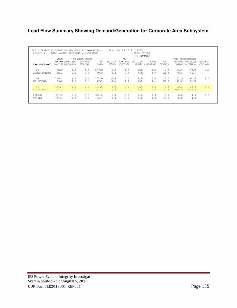
JPS Power System Integrity Investigation
System Shutdown of August 5, 2012
OUR Doc: ELE2013001_REP001 Page 135
Load Flow Summary Showing Demand/Generation for Corporate Area Subsystem


![INDUSTRIAL SAFETY COMMITTEE/TEAM AWARD · [Industrial Safety Committee/Team Award] ... Annual Shutdown Slogan Ben Carson Reading Room Plymouth Mill –LIFE Safety Week - 2016](https://img.dokumen.tips/doc/110x75/5b36c0d17f8b9a310e8b5d8f/industrial-safety-committeeteam-award-industrial-safety-committeeteam-award.jpg)


