Embed Size (px)
Citation preview

Presented to the International Rife Technology Conference.Las Vegas March 2002.
Report of the British Rife Group
British Rife Group
2
Introduction.
I came away from the last Rife conference with a sense of excitement,tinged with sadness. Excitement, because I was convinced that we wererapidly approaching a major breakthrough in Rife technology and thedevelopment of devices that could finally replicate the success of Dr Rife`smedical experiments.But sadness? Well, some of you have technical and historical information thatis not being shared.I think it is time to remind us all that we gather together in a sense ofcommunity with the intention of solving a major scientific mystery, andbenefiting the health of others.Rife research is the collective product of shared knowledge. In the pastvested interests, to include former members of the American MedicalAssociation, have acted to suppress what could have been a fascinating andbeneficial medical technique. Putting it bluntly, lives have been lost becausecommercial advantage was put before the needs of patients.A wise man once said that ‘those who do not learn the lessons of the past arecondemned to repeat them.’ Let us learn from this and share our knowledgefreely. Remember, selfishness is not a virtue.
The British Rife Group was formally established last year as a small teamwith professional expertise in electronic and biological sciences. We arebound together by a determination to provide scientifically proven answers toremaining questions in Rife research.This document is an account of some of our work in progress, and a series ofconclusions from repeatable data. We humbly offer this to the Rife communityin the hope that its’ application may lead to new and improved medicaltreatments.
Stuart Andrews. RTEB
Secretary, British Rife Group.

British Rife Group
3
Contents.
1. The secrets of the 1939 production Beam-Ray Machine. 2. Rife tube fields & effects. 3. Rife Missing Link ? The significance of Impedance in Rife Therapy. -a paper by Aubrey Scoon.

British Rife Group
4
1) Secrets of the 1939 Production Bean Ray Machine.
Through a set of unique circumstances, members of the British Rife Grouprecently had the opportunity to examine and test an original 1939 productionBeam-Ray machine.
History.
This device was discovered walled up in the closet of a former Doctors’surgery. It had lain there undisturbed for some fifty years. The name of theoriginal Doctor who possessed it, and possibly used it, is unknown. Themachine was in a poor state of repair and replacement of some power supplycomponents were necessary before active electronic testing could beundertaken. With the machine was discovered a single page from an un-dated diary. This page contained pencil written dial settings and acorresponding list of diseases, presumably for which the machine was usedto treat.
Physical Description.
The machine consists of a large metal cabinet approximately 24 inches highby 23 inches wide with operational controls on the front panel, test jacks onthe rear panel and a bracket on the left hand side that we believe held aspring loaded arm on which was mounted the Rife plasma tube.A flip up lid was provided on the top of the cabinet in order to gain access tocritical oscillator stages, for calibration purposes and for replacement ofelectron tubes.
Note: Beam Ray
CorporationLogo on lid.

British Rife Group
5
A Beam Ray logo was in evidence on both the top lid and the main accesspanel on the back of the machine.
Operational controls on the front of the machine were as follows:
Far left: Four position band switch oscillator control.Centre: Continuously variable vernier oscillator control.Far right: Power output control.
In addition to the there were various switches for electron tube heaters andan ‘operate’ switch which activated the high voltage feed to the RF poweroscillator.
Block Diagram.
As can be seen in the above block diagram, the machine consists of a fourband oscillator, with an operational range of between 16 Hz to 200,000 Hz.
4 band osc.16Hz- 200Khz
RF Osc+ vari reactance
PSU 1 PSU 2
Plasma Tube

British Rife Group
6
Each of the four ranges are continuously variable. This oscillator has aseparate and relatively well smoothed power supply.
This four band low frequency oscillator feeds a power triode which acts as aself oscillating radio frequency (RF) power oscillator. This is coupled to a Rifetube of Phanotron design via a variable reactance path. A separate highvoltage power supply is provided for this RF oscillator, with a power supplyrail exhibiting a high degree of ripple.
Circuit Description.
For the purpose of this document, I shall be using the British convention ofdescribing electron tubes as ‘valves’; this is to prevent confusion betweendescription of ‘tubes’ and ‘Rife tubes’. (Please don’t protest to yourCongressman on this one !)
Please see Figure 1. (see Appendix for larger view)
Fig. 1.
This is the schematic of the Beam Ray low-frequency oscillator stages.The circuit consists of a standard Wien-bridge oscillator of the HewlettPackard design; this being the most stable of all oscillator designs that wereavailable pre World War II. Please note lamp F1 as part of the feedback pathon the 6SJ7 valve.The use of a Wien-bridge oscillator in this machine gives us our first andmost surprising conclusion: that beam ray machines used sine waves, andnot square waves!
British Rife Group
7
Later electronic testing showed a pure sine wave at the output (across C5) ofthe cathode follower buffer amplifier 6K6A. 1
Another surprise followed when we set the Wien bridge oscillator to the dialsettings for BX (band 4, dial 10) given on the hand-written pencil notes. Weobtained a frequency of 21275 Hz or 21.275Khz. We then set the machine tothe other dial setting in the notes, and found that in all cases the activefrequencies produced by this 1939 machine were 10 x that of the standardCrane-Stafford frequencies of the 1950s.This reminded us of a very strange letter written by Dr. Millbank-Johnson onNovember 4th 1936. Johnson stated that while working in the laboratory, theyhad found ‘a new wave band’ of frequencies. Johnson goes on to mentionthat this new band broke glass in the laboratory. Frequencies of 21275 Hz etc. are supersonic in that they cannot be heard bythe human ear. But when generated at a sufficiently high amplitude, theyhave the capability to cause resonant destruction of glass and other fragilematerials. Our conclusion then, is that this explains the effect that Johnsonobserved in 1936.The use of 10 x Crane frequencies may be of great significance to the actualoperational uses of modern Rife technology. We urge researchers to try thisout.It is noted in the bottom right hand of the schematic that a 6SN7 valve( double triode) remains unconnected and performs no electronic function. Itis speculated that this may have been intended as part of a multivibrator (flip-flop) circuit to provide gating or, to act as another stage of bufferamplification. We simply don’t know at this time.
The Wien-bridge oscillator stages of this machine produce a highly stablesine wave output variable from 0 to 50 volts, peak to peak.
1 A quick note of explanation: at no time since the recovery of this machine have any of thepre-set oscillator controls been adjusted in any way. We left things exactly as we found them.In other words, just as they had been set in 1939 or in the 1940s.

British Rife Group
8
We now move on to the main RF stage. See Figure 2. (See Appendix forlarger version)
Fig. 2
This consists of a medium MU 812A power triode coupled in a tuned anodeself-oscillating configuration. A full wave power supply is provided by two 866A diode valves feeding asimple LC smoothing circuit (L1-C2). RF choke L2 prevents radio frequenciesfrom being reflected back into the power supply. It is noted that the mainsmoothing capacitor C2 is only 2 uF (2 Microfarads) resulting in a high ripplecurrent on the main power supply rail.This high voltage rail operates at approximately 990 V while the oscillator isrunning. A Jack socket is provided at J2 to inject an external frequency source or,alternatively (and more likely) to monitor the output of the Wien-bridge duringcalibration. Jack socket J3 forms the main cathode feed to the 812A triodeand would be a convenient monitoring point to measure combined grid andanode current.The 812A triode produces an output in the region of 40 Watts RF, and Riferesearchers will appreciate that this is a far lower power than we have beenled to believe was used in 1939.Main carrier frequency was measured at 4.6 Mhz with harmonics being notedat 2.15 Mhz and 9.09 Mhz. This is to be expected as there is no harmonicsuppression in this circuit.
There are a number of features in this circuit that are both unique andingenious.

British Rife Group
9
• Firstly, the main RF tuning capacitor C1 is series fed to ground by theplasma tube (at Jack point J1). This means that the plasma tube itselfforms part of a variable capacitor, and that it will be reactive when broughtnear any object or patient. This means that the main frequency tuning ofthe RF oscillator will change according to the individual capacitance of apatient. We believe this to be significant, particularly as contemporaryaccounts describe the tube being placed within 10 inches of the patient.
• Secondly, the ground wire output of the plasma tube is fed to ground via
R4 rheostat ( or in modern terms, a variable resistance ) This was found tobe set at 2.2 Kilo-ohms. Such a resistor at this point in the circuit willprovide the means to precisely control the impedance match of one of themany characteristics of the plasma tube. It is worth remembering that thelater Vern-Thompson machine incorporated a similar arrangement, butused switched resistors instead of a variable one.
• Thirdly, a combination of 120Hz ripple ( in the USA ) on the main highvoltage power supply rail and a 60Hz ripple noted at pin 1 (cathode) of the812A valve will result in a 60Hz gating, or additional modulation, of thesignal passing through this valve. This is the reason, we suspect, whyPhilip Hoyland, the designer, did not use the 6SN7 as a gating device inthe Wien-bridge oscillator. He found another way to achieve the gatingeffect with greater simplicity !
Modulation from the Wien bridge is applied across the grid via L4. The circuitneeds about 50 volts peak to peak, at this point, to drive the 812A to full(100%) modulation. It is noted that the Wien-bridge amplitude control R4enables modulation depth to be varied. During our experiments we found thatthe best results were obtained at levels of 100% modulation.The effect of applying this sort of modulation to the grid of a self oscillatingRF triode are two fold.
• Firstly; It places a changing amplitude audio voltage on the grid whichmodulates the 812A. This results in amplitude modulation, that is, thestrength of the RF power oscillator changes.
• Secondly; the change of overall grid voltage caused by the appliedmodulation signal will move the 812A up & down its operating curve. Thisaffects the reactance of the valve.
Because the 812A is a free running RF oscillator, changing the reactanceresults in a change of frequency.In short, frequency modulation. What does this mean ?It means that our 812A is generating a 4.6Mhz carrier that is both amplitudeand frequency modulated.
In conclusion. This 1939 circuit incorporates a variable reactance poweroscillator, producing AM & FM components. The RF voltage swings up to 2Kilo volts. This is different from modern Rife-Bare devices which produce a

British Rife Group
10
low voltage, high current signal from a linear amplifier. The 1939 machinegenerates a high voltage, low current waveform that drives the plasma tube.
Enough already ! - lets see some wave-forms.
British Rife Group
11
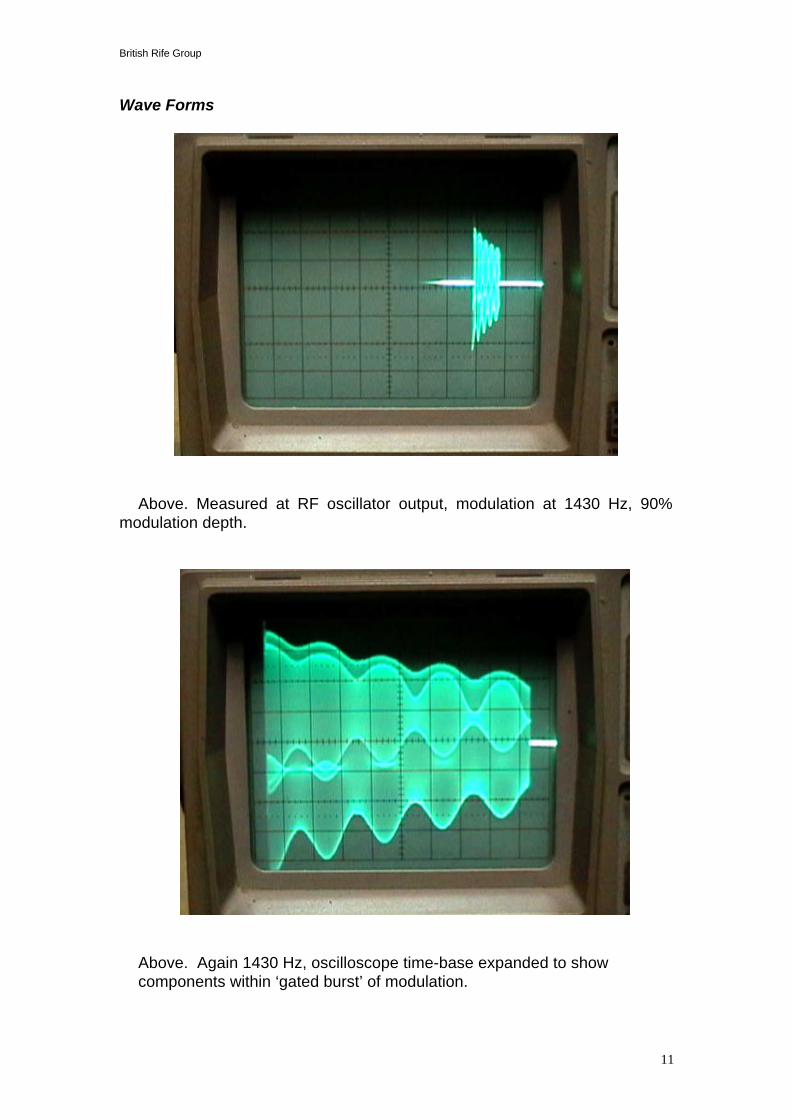
Wave Forms
Above. Measured at RF oscillator output, modulation at 1430 Hz, 90%modulation depth.
Above. Again 1430 Hz, oscilloscope time-base expanded to show
components within ‘gated burst’ of modulation.
British Rife Group
12
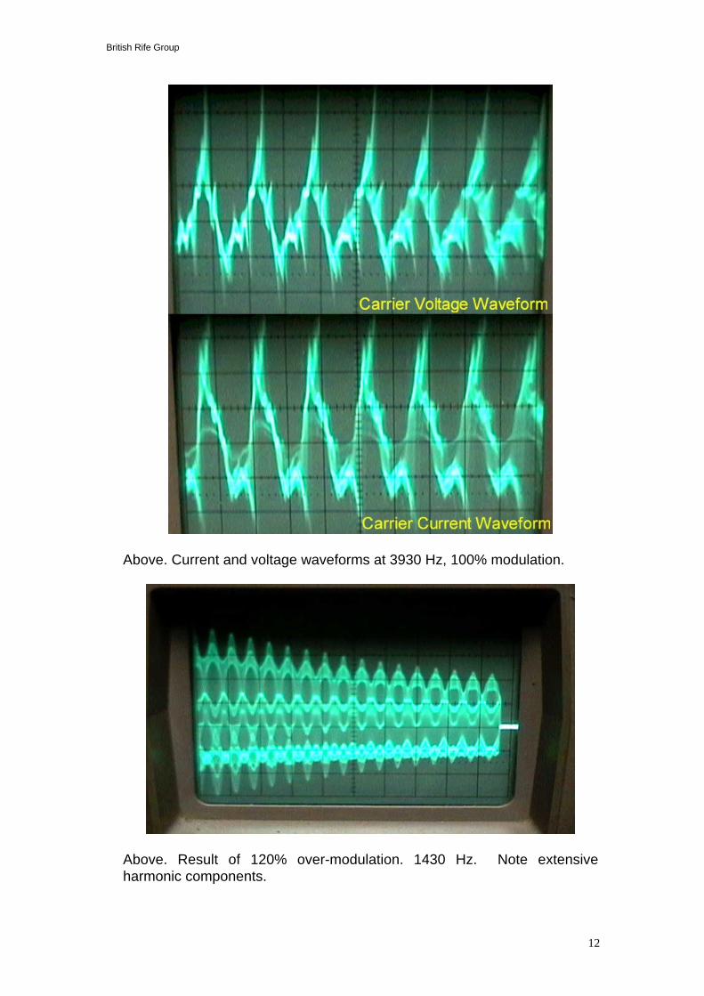
Above. Current and voltage waveforms at 3930 Hz, 100% modulation.
Above. Result of 120% over-modulation. 1430 Hz. Note extensive
harmonic components.

British Rife Group
13
Above. 1000 Hz modulation at 35%. Note with a USA/Canadian mainsfrequency of 60 Hz, the output of the 1939 machine gates at approximately 16ms (milli-seconds). With European mains frequency of 50 Hz, gating willoccur at approximately 20 ms.
Time base expanded version of above waveform.

British Rife Group
14
Pictures of the Machine.
Above. Wien bridge modulator oscillator with valves removed.
Above. RF oscillator section. Rectifiers on the left, main tuning coil on right.
British Rife Group
15
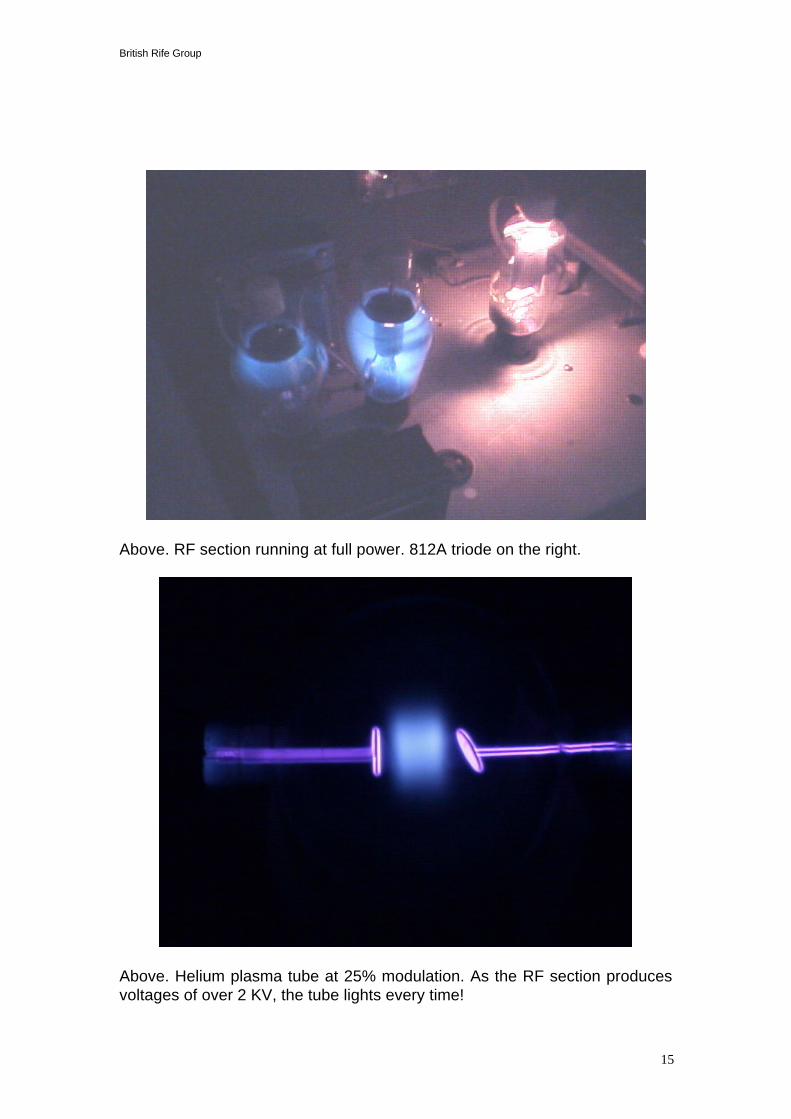
Above. RF section running at full power. 812A triode on the right.
Above. Helium plasma tube at 25% modulation. As the RF section producesvoltages of over 2 KV, the tube lights every time!

British Rife Group
16
Appendixes
Figure 1: Beam Ray LF Oscillator.
Figure 2: RF power section and output.

British Rife Group
17

British Rife Group
18

British Rife Group
19
2) Rife tube fields & effects.
During our experiments with a number of Rife type devices, we observed aspecific and directional field output from the plasma tube. See Figure 1.
Fig. 1
A narrow ( 5 degree wide ) electric field was detected, and this forms a planearound the plasma tube. See Figure 2.
Fig 2.
( Only half the field is shownin this picture )
The plane of the field “wobbles” around the tube centre axis, as M.O.Rfrequency is varied.
5Ø
Electric field vector -15Ø
from +ion axis
Positiveion beam

British Rife Group
20
Low light observations and special photographic exposures seem to suggestevidence of differing electron cloud formations around the angled electrode.The density and position of these electron clouds is dependant on appliedvoltage, gas type and modulation excitation.It is our belief that the electron clouds form a crude lens which serve toseparate and deflect plasma ions and give rise to a focusing of the electricfield.The existence of such a narrow, directional, electric field may have treatmentimplications. We are reminded that Dr Rife was quoted as stating that heused a Heathkit field strength meter to locate some sort of directional energyemission from the plasma tube, and that this energy was “aimed” to thepatient.

British Rife Group
21
3) Impedance- the missing link in Rife Research ?-a paper by Aubrey Scoon.