Embed Size (px)
Citation preview

OTIC USACERL ADP Report M-91/24S rSeptember 1991
US Army Corpsof EngineersConstruction Enginering A D-A 243 66Research Laboratory 111l1lMIl1l lit
Cathodic Protection DiagnosticComputer Program for Sacrificialand Impressed Current Systems:Overview and User's ManualbyVicki L. Van BlaricumC. David Page, Jr.Kim ReinkeAshok Kumar
The total cost of corrosion at Army facilities is asignificant percentage of maintenance and repairbudgets. Corrosion in underground gas piping ispaticularly costly because pipe damage is diffi-cult to determine or assess until a leak occurs.Cost-effective maintenance of underground gaspiping and other structures requires that cathodicprotection (CP) systems operate properly andthat some measure of current and projected pipecondition be available. To meet this requirement,data on CP systems must be constantly mon-itored, and CP faults indicated by the data mustbe correctly recognized and interpreted. The CPDiagnostic computer program helps meet therecordkeeping, analysis, and maintenance re-quirement of sacrificial and impressed currentcathodic protection systems.
CP Diagnostic is a data base management pro-gram consisting of two microcomputer systems: 91 -18787Sacrificial CP Diagnostic and Impressed CurrentCP Diagnostic. This User's Manual gives anoverview of the capabilities of CP Diagnostic, andstep-by-step instructions for its installation anduse.
Approved for public release; distribution is unlimited. 91 ,

The contents of this report are not to be used for advertising, publication,or promotional purposes. Citation of trade names does not constitute anofficial indorsement or approval of the use of such commercial products.The findings of this report are not to be construed as an official Depart-ment of the Army position, unless so designated by other authorizeddocuments.
DESTROY THIS REPORT WHEN IT IS NO LONGER NEEDED
DO NOT RETURN IT TO THE ORIGINATOR

1.RAGENCYU EPONLYO(LeavAIBNaForm ApprovedREPOT DOUMETATIN PA E - OMB No. 0704-0188
Public reporting burden for this collection of infor dion is estimated to average f hour pe r s c i fiiewng instructions, eching existing data souces,gathering and Curntaining the data needed snd completing and reviewing the collection of inPomtion. Send comnts regarding this burden estimate or any other a13 ect of thscollection of information, including sugge~iore for reducing this burden, to Washington H-eadquarters Senivos Directorate for information Operations and Reports, 1215 Jefferson
Davis Highway. Suite 1204, Arlington, VA 22202-4302, and to the Office of Management and Budget. Paprwr Reduction Project (0704-0188). Washington, DC 20503.1. AGENCY USE ONLY (Leave Blank) 2. REPORT DATE 3. REPORT TYPE AND DATES COVEREDI September 1991 Final
4. TITLE AND SUBTITLE 5. FUNDING NUMBERSCathodic Protection Diagnostic Computer Program for Sacrificial andImpressed Current Systems: Overview and User's Manual PE 162731
P. AUTHOR(S) PR AT41WU MB
Vicki L. Van Blaricum, C. David Page, Jr., Kim Reinke, and Ashok Kumar TO C 19
7. PERFORMING ORGANIZATION NAME(S) AND ADDRESS(ES) 8. PERFORMING ORGANIZATIONREPORT NUMBER
U.S. Army Construction Engineering Research Laboratory (USACERL)AD M-12PO Box 9005AD M-12
Champaign, IL 61826-9005
9. SPONSOR ING'MONITORIN* AGENCY N.AME S) AP'O ADDRESS(ES) 10. SPONSORING/MONITORINGAGENCY REPORT NUMBER
U.S. Army Engineering and Housing Support CenterATTN: CEHSC-FU-SFort Belvoir, VA 22060-5516
11. SUPPLEMENTARY NOTES
Copies are available from the National Technical Information Service, 5285 Port Royal Road,Springfield, VA 2216-1
1 2a. DISTRIBUTION/AVAILABILITY STATEMENT 12b. DISTRIBUTION CODE
Approved for public release; distribution is unlimited.
13. ABSTRACT (Maximum 200 words)
The total cost of corrosion at Army facilities is a significant percentage of maintenance and repair budgets.Corrosion in underground gas piping is particularly costly because pipe damage is difficult to determine orassess until a leak occurs. Cost-effective maintenance of underground gas piping and other structuresrequires that cathodic protection (CP) systems operate properly and that some measure of current andprojected pipe condition be available. To meet this requirement, data on CP systems must be constantlymonitored, and CP faults indicated by the data must be correctly recognized and interpreted. The CPDiagnostic computer program helps meet the recordkeeping, analysis, and maintenance requirement ofsacrificial and impressed current cathodic protection systems.
CP Diagnostic is a data base management program consisting of two microcomputer systems: SacrificialCP Diagnostic and Impressed Current CP Diagnostic. This User's Manual gives an overview of thecapabilities of CP Diagnostic, and step-by-step instructions for its installation and use.
14. SUBJECT TERMS 15. NUMBER OF PAGES
Cathodic Protection Diagnostic Computer Program (CP Diagnostic) 156underground gas piping maintenance 16. PRICE CODE
17 SECURITY CLASSIFICATION 18. SECURITY CLASSIFICATION 19. SECURITY CLASSIFICATION 20. LIMITATION OF ABSTRACT
OF REPORT OF THIS PAGE OF ABSTRACT
Unclassified Unclassified Unclassilied SAR
NSN 7540-01 -280-5500 Swxad Fon 28 (lev. 2-89)Prownbed by ANSI Std 239-18298-102

NOTICE TO PROGRAM RECIPIENTS
This program is furnished by the U.S. Government and is accepted and used by the recipient withthe express understanding that the Government makes no warranty, expressed or implied, concerning theaccuracy, completeness, reliability, usability, or suitability for any particular purpose of the informationand data contained in this program or furnished in connection therewith, and the United States shall beunder no liability whatsoever to any person by reason of any use made thereof.
The program belongs to the Government. Therefore, the recipient further agrees not to assert 2n1proprietary rights therein or to represent this program to anyone as other than a Government programThe recipient also agrees that the program and all documents related thereto, including all copies and ver-sions (except when expressly authorized otherwise) in possession thereof, will be discontinued from useor destroyed upon request by the Government.
The program is to be used only in the public interest and/or the advancement of science and willnot be used by the recipient to gain unfair advantage over any client or competitor. Whereas the recipientmay charge clients for the ordinary costs of applying the program, the recipient agrees not to levy acharge, royalty, or proprietary usage fee (except to cover any normal copying and/or distribution costs)upon any client for the development or use of the received program. Recipients deciding to modify andre-market the program will be required to comply with a separate agreement. Only minor or temporarymodifications will be made to the program (e.g., necessary corrections or changes in the format of inputor output) without written approval from the Government. Should the program be furnished by therecipient to a third party, the recipient is responsible to that third party for any support and upkeep of theprogram. Information on the source of the program will be furnished to anyone requesting suchinformation.
The accuracy of this program depends on user-supplied data. It is the user's responsibility tounderstand how the input data affects the program output and to use the output data only as intended.
All documents and reports conveying information obtained as a result of the use of the program bythe recipient will acknowledge the Corps of Engineers, Department of the Army, as the origin of theprogram. All such documentation will state the name and version of the program used by the recipient.
CP Diagnostics is not to be used for advertising, publication, or promotional purposes. Citation oftrade names does not constitute an official endorsement or approval of the use of such commercialproducts. Program findings are not to be construed as an official Department of the Army position, unlessso designated by other authorized documents.

FOREWORD
This work was performed for the Office of the Chief of Engineers (OCE) under Project4A162731AT41. Work Unit MB, Task C19, "Corrosion Mitigation and Management Systems." Fundingwas also provided by the U. S. Army Engineering and Housing Support Center (USAEHSC) under theFacilities Engineering Applications Program (FEAP). The technical monitor was Mr. Malcolm E.McLeod, CEHSC-FU-S.
The work was conducted by the Engineering and Materials Division (EM) of the U.S. ArmyConstruction Engineering Research Laboratory (USACERL). The Principal Investigator was Dr. AshokKumar. The software was developed by Kim Reinke of Argus Systems, Urbana, Illinois. The technicalassistance provided by Mr. Malcolm McLeod, Mr. Ivan Leef, and Mr. Thomas Spoemer of theUSAEHSC and by Mr. Vincent Hock, USACERL, was invaluable to the successful completion of thiswork. Dr. Paul A. Howdyshell is acting Chief, USACERL-EM. The USACERL technical editor was Mr.William J. Wolfe, Information Management Office.
COL Everett R. Thomas is Commander and Director of USACERL, and Dr. L.R. Shaffer isTechnical Director.
A t i r
I*. ..............
sit 1 AC
3
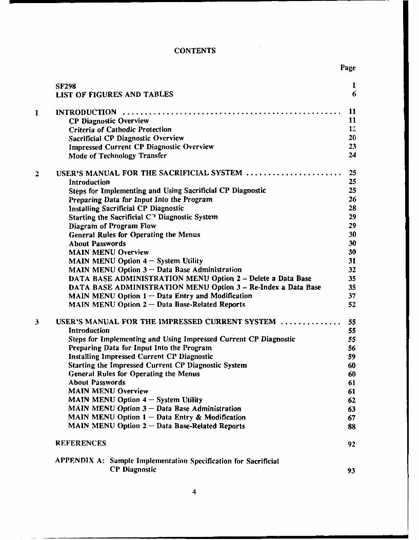
CONTENTS
Page
SF298 1LIST OF FIGURES AND TABLES 6
INTRODUCTION .................................................. 11CP Diagnostic Overview 11Criteria of Cathodic Protection 1,7
Sacrificial CP Diagnostic Overview 20Impressed Current CP Diagnostic Overview 23Mode of Technology Transfer 24
2 USER'S MANUAL FOR THE SACRIFICIAL SYSTEM ...................... 25Introduction 25Steps for Implementing and Using Sacrificial CP Diagnostic 25Preparing Data for Input Into the Program 26Installing Sacrificial CP Diagnostic 28Starting the Sacrificial C-1 Diagnostic System 29Diagram of Program Flow 29General Rules for Operating the Menus 30About Passwords 30MAIN MENU Overview 30MAIN MENU Option 4 - System Utility 31MAIN MENU Option 3 - Data Base Administration 32DATA BASE ADMINISTRATION MENU Option 2 - Delete a Data Base 35DATA BASE ADMINISTRATION MENU Option 3 - Re-Index a Data Base 35MAIN MENU Option 1 - Data Entry and Modification 37MAIN MENU Option 2 - Data Base-Related Reports 52
3 USER'S MANUAL FOR THE IMPRESSED CURRENT SYSTEM .............. 55Introduction 55Steps for Implementing and Using Impressed Current CP Diagnostic 55Preparing Data for Input Into the Program 56Installing Impressed Current CP Diagnostic 59Starting the Impressed Current CP Diagnostic System 60General Rules for Operating the Menus 60About Passwords 61MAIN MENU Overview 61MAIN MENU Option 4 - System Utility 62MAIN MENU Option 3 - Data Base Administration 63MAIN MENU Option 1 - Data Entry & Modification 67MAIN MENU Option 2 - Data Base-Related Reports 88
REFERENCES 92
APPENDIX A: Sample Implementation Specification for Sacrificial
CP Diagnostic 93
4

CONTENTS (Cont'd)
Page
APPENDIX B: Background Data Collection Forms for SacrificialCP Diagnostic 107
APPENDIX C: Diagram of Program Flow for Sacrificial CP Diagnostic 112APPENDIX D: Sample Implementation Specification for Impressed
Current CP Diagnostic 118APPENDIX E: Relationships Between System Components 133APPENDIX F: Background Data Collection Forms for Impressed
Current CP Diagnostic 136APPENDIX G: Diagram of Program Flow for Impressed Current
CP Diagnostic 144
DISTRIBUTION
5
FIGURES
Number Page
1-1 Structure-to-soil potential versus time upon application ofcathodic protection 13
1-2 IR drop in structure-to-soil potential 17
2-1 MAIN MENU (sacrificial) 31
2-2 GENERAL SYSTEM INFORMATION screen (sacrificial) 32
2-3 DATABASE ADMINISTRATION MENU screen (sacrificial) 33
2-4 SELECTING A DATABASE screen (sacrificial) 34
2-5 MISSING FILES screen (sacrificial) 35
2-6 DELETE A DATABASE screen (sacrificial) 36
2-7 REBUILD INDEX FILES screen (sacrificial) 37
2-8 ADD/MODIFY/DELETE MENU screen (sacrificial) 38
2-9 ENTER ADD/EDIT PASSWORD screen (sacrificial) 39
2-10 STRUCTURE TYPE SPECIFICATION screen (sacrificial) 39
2-11 PIPE SECTION IDENTIFICATION screen (sacrificial) 40
2-12 TANK IDENTIFICATION screen (sacrificial) 40
2-13 ADD/EDIT PIPE BACKGROUND DATA screen (sacrificial) 41
2-14 ADD/EDIT UNDERGROUND TANK BACKGROUND DATA screen (sacrificial) 42
2-15 ADD/EDIT BACKGROUND DATA (isolation joints-sacrificial) 43
2-16 TEST SITE IDENTIFICATION screen (sacrificial) 43
2- 17 ADD/EDIT TEST SITE DATA screen (sacrificial) 45
2-18 ADD/EDIT TEST SITE INITIAL POTENTIALS screen (sacrificial) 45
2-19 ADD/EDIT ANODE DATA screen (sacrificial) 46
2-20 ANODE CURRENT OUTPUT screen (sacrificial) 46
6

FIGURES (Cont'd)
Number Page
2-21 ADD/EDIT REPAIR DATA screen (sacrificial) 47
2-22 ADD/EDIT TEST SITE FIELD DATA screen (sacrificial) 48
2-23 TEST SITE FIELD COLLECTION DATA screen with data table (sacrificial) 49
2-24 ANODE CURRENT FIELD DATA (sacrificial) 49
2-25 ENTER DELETE PASSWORD screen (sacrificial) 50
2-26 DELETE TANK DATA screen (sacrificial) 51
2-27 DELETE TEST SITE DATA screen (sacrificial) 52
2-28 CP CRITERIA MENU screen (sacrificial) 53
3-1 MAIN MENU (impressed current) 62
3-2 GENERAL SYSTEM INFORMATION screen (impressed) 63
3-3 DATABASE ADMINISTRATION MENU screen (impressed current) 64
3-4 SELECTING A DATABASE screen (impressed) 65
3-5 MISSING FILES screen (impressed) 66
3-6 DELETE A DATABASE screen (impressed) 67
3-7 REBUILD INDEX FILES screen (impressed) 68
3-8 ADD/MODIFY/DELETE MENU (impressed) 69
3-9 ENTER ADD/EDIT PASSWORD screen (impressed) 70
3-10 SELECTING A RECTIFIER screen (impressed) 70
3-11 SPECIFY PIPE OR TANK screen (impressed) 71
3-12 ADD/EDIT RECTIFIER DATA screen #1 (impressed) 72
3- 12a ADD/EDIT RECTIFIER DATA screen #2 (impressed) 72
3-13 JUNCTION BOX IDENTIFICATION scrcen (impressed) 73
3-14 GROUND BED DATA screen #1 (impressed) 73
7

FIGURES (Cont'd)
Number Page
3-15 GROUND BED DATA screen #2 (impressed) 74
3-16 WATER STORAGE TANK ANODE DATA screen (impressed) 75
3-17 STRUCTURE TYPE SPECIFICATION screen (impressed) 75
3-18 PIPE SECTION IDENTIFICATION screen (impressed) 76
3-19 TANK IDENTIFICATION screen (impressed) 77
3-20 ADD/EDIT PIPE BACKGROUND DATA screen (impressed) 77
3-21 ADD/EDIT UNDERGROUND TANK BACKGROUND DATA screen (impressed) 78
3-22 ADD/EDIT WATER TANK BACKGROUND DATA screen (impressed) 78
3-23 ISOLATION JOINTS LOCATION screen (impressed) 79
3-24 TEST SITE IDENTIFICATION screen (impressed) 80
3-25 ADD/EDIT TEST SITE DATA screen #1 (impressed) 80
3-26 ADD/EDIT TEST SITE DATA screen #2-initial potentials (impressed) 81
3-27 REPAIR DATA screen (impressed) 82
3-28 FIELD COLLECTION MENU screen (impressed) 82
3-29 TEST SITE COLLECTION screen (impressed) 83
3-30 TEST SITE COLLECTION screen #2 (impressed) 84
3-31 ADD/EDIT RECTIFIER FIELD DATA screen (impressed) 84
3-32 ANODE CURRENT DATA screen (impressed) 85
3-33 DELETE PASSWORD screen (impressed) 86
3-34 DELETE MENU screen (impressed) 86
3-35 DELETE RECTIFIER DATA screen (impressed) 87
3-36 DELETE STRUCTURE DATA screen (impressed) 88
3-37 DELETE TEST SITE DATA screen (impressed) 89
8

FIGURES (Cont'd)
Numnber Page
3-38 CP CRITERIA MENU screen (impressed) 90
TABLE
I Summary of Cathodic Protection Criteria 19
9

CATHODIC PROTECTION DIAGNOSTIC COMPUTER PROGRAMFOR SACRIFICIAL AND IMPRESSED CURRENT SYSTEMS:OVERVIEW AND USER'S MANUAL
1 INTRODUCTION
The total cost of corrosion at Army facilities is a significant percentage of maintenance and repairbudgets. Corrosion of underground gas piping, underground storage tanks, and water storage tanks isparticularly costly because the presence and extent of damage are difficult to determine until a leak occurs.The normal approach taken by Army Directorates of Engineering and Housing (DEHs) to leakmaintcr, ance is therefore corrective rather than preventive, to take maintenance measures only after a pipeleaks. One effective method to prevent corrosion-induced leaks is the use of cathodic protection.However, cathodic protection systems must be properly maintained to achieve peak effectiveness. Propermaintenance of cathodic protection systems requires recording and evaluating a large amount of data.
The U.S. Army Construction Engineering Research Laboratory (USACERL) has developed a com-puter-based approach for preventive rather than corrective corrosion mitigation. This approach consistsof two computer systems. The Cathodic Protection Diagnostic Computer Program (CP Diagnostic) helpsthe user maintain the appropriate data on cathodic protection systems and recognize possible malfunctionsof these systems. The Gas Piper Computer System (GPIPER) allows the user to maintain detailed dataabout gas piping, predicts pipe condition, and identifies the pipes that need leak prevention maintenance.This report describes CP Diagnostic.
CP Diagnostic Overview
CP Diagnostic maintains background information about CP systems (e.g., number and type ofanodes, date of installation) as well as data from field measurements (e.g., pipe-to-soil potential, rectifiercurrents and voltages). CP Diagnostic generates reports that present relevant data, emphasizing informa-tion t1;:'t suggests CP system malfunctions. A planned revision to the program will also inform the userof the spccific repair needs indicated by the data.
CP Diagnostic is divided into two parts: Sacrificial CP Diagnostic manages information related toSacrificial CP systcms, and Impressed Current CP Diagnostic manages data related to impressed currentCP systems. Sacrificial CP Diagnostic has been tested at Fort Riley, Kansas, and Impressed Current CPDiagnostic has been tested at Fort Hood, Texas. 2
R. Guglomo. et al., (;PIPER Inplementation Guide and User Manual. Draft Technical Report (U.S. Army ConstructionEngineering Research Laboratory [USACERLI. 1990); Further discussion of GPIPER data entry screens and reports is includedin: Ashok Kumar, Margaret Blyth. and Michael Bergcnhousc, "Implementation of a Pipe Corrosion Management System."Prot-ecaings of the National Association of Corrosion Enginecrs (San Francisco, 1987).Cathodic Protection Module at Fort Riley, Kansas (Corrpro Companies, Inc., Schaumburg, IL, 28 February 1989); CathodicProtection Computer System Impressed Current Field Investigotion (HARCO Technologies Corp., Medina, OH. July 1989).
11

Both the Sacrificial and Impressed systems are user-friendly programs writtrn in the dBASE III+programming language and compiled with the Clipper compiler.3 Because these programs are compiled,the only software required is the program disk(s) supplied. CP Diagnostic operates on an IBM-compatiblemicrocomputer system with 640K of Random Access Memory (RAM). A hard drive is required becauseof the large amounts of data stored by the program. It supports both color and monochrome monitors.The program can be configured to support most dot matrix and laser printers.
Capabilities of the two parts of CP Diagnostic are discussed later in this chapter. An overview ofthe data that is required and the reports that are generated is given. For more detail, refer to the figures(located in later chapters) that are noted throughout this overview.
IMPORTANT NOTE: CP Diagnostic stores data for both pipes and tanks. The word "structure"will be used throughout the text to denote both pipes and tanks in general. The words "pipe" and "tank"will only be used if the information being given is specific to either pipes OR tanks. Thus, the word"structure" as used in this text means "pipe and/or tank."
Before the programs themselves are discussed, it is important for the user to understand the criteriathat are used to determine whether or not cathodic protection is being achieved on a structure. Thisunderstanding is critical to the successful application of CP Diagnostic. The section should be readcarefully before the programs are used.
Criteria of Cathodic Protection
Introduction
One of the key functions of CP Diagnostic is to pinpoint malfunctions in CP systems. It is thereforeessential to understand the criteria which are used to determine whether or not cathodic protection of astructure is being achieved. No one simple criterion has been accepted by all cathodic protectionengineers and that can be practicably measured in the field under all circumstances. Therefore, CPDiagnostic has been designed such that program users may select from several of the criteria currentlyused by cathodic protection enginet rs, or they may enter their own criterion as dictated by regulation,management, or experience. For further information on cathodic protection system operation, maintenance,and criteria selection, the reader should consult the references given at the end of this report.
Explanation of Potential Changes
In order to understand the criteria of CP, it is critical to understand the changes that occur in theelectrical potential of a structure when the protective current is applied to it. Husock explains:
It should be noted that cathodic protection when properly appli-d produces a change in the potentialof a structure with respect to a reference electrode placed in the soil in proximity to that structure. Thec:tlhodtic proteclion current makes the potential thus measured more negative than the potential was
dBASE is a registered trademark of Ashton-Tate, Torrence, CA. Clipper is a registered trademark of the Nantucket Corp., LosAngeles. CA.Husock. Bernard. Evaluation of Cathodic Protection Criteria, Report Number ESL TR-79-14 (Headquarters. Air ForceEngineering and Services Center [HQAFESCI. April 1979), p. 12-14.
12

before the current was applied, and the amount of change produced is a measure of the effectivenessof the cathodic protection at that location.
The changes in electrical potential of the structure (with respect to a copper-copper sulfate referenceelectrode) that occur when the cathodic protection current is applied are depicted graphically in Figure 1-1.Before current is applied, the structure is at its original or "native" potential. When the current is applied,there is a change in potential in the negative direction at the instant the current is turned on. As thecurrent is continuously applied over an extended period of time, the potential tends to increase negativelybecause of polarization. According to Husock, "polarization of a structure is a phenomenon which occursover a long time period and a structure may not be entirely polarized even after the cathodic protectionsystem has been in operation for many months." If the current is interrupted after the structure haspolarized, the potential becomes less negative at the instant of turn-off. The potential then begins todecay, or depolarize, back to the original or native potential.
CP Criteria
The guidance typically used by corrosion engineers concerning the criteria of cathodic protectionis contained in two Recommended Practices (RPs) published by the National Association of CorrosionEngineers (NACE): RP-01-69, "Control of External Corrosion on Underground or Submerged MetallicPiping Systems," and RP-02-85, "Control of External Corrosion on Metallic Buried, Partially Buried, orSubmerged Liquid Storage Systems." Although there are some differences in wording between the two
'O)tv " I0t1rt io f
l I Pclor'izcktion D!ec: o\1
tlltlI k eqjon of" 100,-V• I pi(I-Ir ': -ot Inn decoy
,~~~~~; cn ion~t, h~
"0, I\ nstant E+ Potential
This NOos.Lretrnt ;_ the
, - true pe~or zed potentiot ofI-the structure IR free (no
0 current F((c*;n9 to theP structure) If you achieve
• t ,/ IF -~ -<on 10P of -085 V you hovent'tc-rupt 'i net the -085 V NACE-10 c .- teron
OW V , to
Inc,wh- pr, o
Figure 1-1. Structure-to-soil potential versus time upon application of cathodic protection.
13

RPs due to the different structures that are being described, the content is essentially the same. Refer to
Figure 1-1 for a graphical representation of the criteria below, taken from NACE RP-01-69:5
6.1 Introduction
6.1.1 This section lists criteria for cathodic protection which, when complied with eitherseparately or collectively, will indicate that adequate cathodic protection of a metallic pipingsystem in its electrolyte has been achieved.
6.2 General
6.2.1 The objective of using cathodic protection is to control the corrosion of metallicsurfaces in contact with electrolytes.
6.2.2 The selection of a particular criterion for achieving this objective depends, in part, uponpast experience with similar structures and environments wherein the criterion has been usedsuccessfL'ly.
6.2.3 The criteria in Section 6.3 have been developed through laboratory experiment or havebeen empirically determined by evaluating data obtained from successfully operated cathodicprotection systems. It is not intended that persons responsible for corrosion control be limitedto these criteria if it can be demonstrated by other means that the control of corrosion hasbeen achieved.
6.2.4 Voltage measurements on pipelines are to be made with the reference electrode locatedon the electrolyte surface as close as practicable to the pipeline. Such measurements on allother structures are to be made with the reference electrode positioned as close as feasible tothe structure surface being investigated. Consideration should be given to voltage (IR) dropsother than those across the structure-to-electrolyte boundary, the presence of d:,ssimilar metals,and the influence of other structures for valid interpretation of voltage measurements. [Note:RP-02-85 adds the following at this point: Measurements made with a reference electrodelocated on blacktop pavement or concrete slab may be in error.]
6.2.5 No one criterion for evaluating the effectiveness of cathodic protection has proved tobe satisfactory for all conditions. Often a combination of criteria is needed for a singlestructure.
6.3 Criteria
6.3.1 For steel and cast iron structures:
6.3.1.1 A negative (cathodic) voltage of at least 0.85 volt as measured between the structuresurface and a saturated copper-copper sulfate reference electrode contacting the electrolyte.Determination of this voltage is to be made with the protective current applied.
6.3.1.2 A minimum negative (cathodic) voltage shift of 300 millivolts, produced by theapplication of protective current. The voltage shift is measured between the structure surfaceand a stable reference electrode contacting the electrolyte. This criterion of voltage shift doesnot apply to structures in contact with dissimilar metals.
"Control of External Corrosion on Underground or Submerged Metallic Piping Systems," Recommended Practice RP-01-69(National Association of Corrosion Engineers [NACE], Houston, TX, 1983 revision), p. 6-7.
14

6.3.1.3 A minimum negative (cathodic) polarization voltage shift of 100 millivolts measuredbetween the structure surface and a stable reference electrode contacting the electrolyte. Thispolarization voltage shift is to be determined by interrupting the protective current andmeasuring the polarization decay. When the current is initially interrupted, an immediatevoltage shift will occur. The voltage reading after the immediate shift shall be used as thebase reading from which to measure polarization decay....
6.3.2 For aluminum structures:
6.3.2.1 A minimum negative (cathodic) voltage shift of 150 millivolts, produced by theapplication of protective current. The voltage shift is measured between the structure surfaceand a stable reference electrode contacting the electrolyte. (See precautionary notes in 6.3.2.3and 6.3.2.4.)
6.3.2.2 A minimum negative (cathodic) polarization voltage shift of 100 millivolts measuredbetween the structure surface and a stable reference electrode contacting the electrolyte. Thispolarization voltage is to be determined by interrupting the protective current and measuringpolarization decay. When the current is initially interrupted, and immediate voltage shift willoccur. The voltage reading after the immediate shift shall be used as the base reading fromwhich to measure polarization decay. (See precautionary notes in 6.3.2.3 and 6.3.2.4.)
6.3.2.3 PRECAUTIONARY NOTE - Excessive Voltages: Notwithstanding the alternativeminimum criteria in 6.3.2.1 and 6.3.2.2, aluminum, if cathodically protected at voltages morenegative than -1.20 volts measured between the structure surface and a saturated copper-copper sulfate reference electrode contacting the electrolyte and compensated for the voltage(IR) drops other than those across the structure-electrolyte boundary, may suffer corrosion asthe result of the build-up of alkali on the metal surface. A voltage more negative than -1.20volts should not be used unless previous test results indicate no appreciable corrosion willoccur in the particular environment.
6.3.2.4 PRECAUTIONARY NOTE - Alkaline Soil Conditions: Since aluminum may sufferfrom corrosion under high pH conditions and since application of cathodic protection tendsto increase the pH at the metal surface, careful investigation or testing should be made beforeapplying cathodic protection to stop pitting attack on aluminum structures in environmentswith a natural pH in excess of 8.0.
6.3.3 For copper structures:
6.3.3.1 A minimum negative (cathodic) polarization voltage shift of 100 millivolts measuredbetween the structure surface and a stable reference electrode contacting the electrolyte. Thispolarization voltage shift is to be determined by interrupting the protective current andmeasuring the polarization decay. When the current is initially interrupted, an immediatevoltage shift will occur. The voltage reading after the immediate shift shall be used as thebase reading from which to measure polarization decay.
Army guidance on the criteria of cathodic protection is given in the following publications:
" TM 5-811-7 Electrical Design, Cathodic Protection" CEGS 16640 "Cathodic Protection System (Sacrificial Anode)"• CEGS 16641 "Cathodic Protection System (Steel Water Tanks)"" CEGS 16642 "Cathodic Protection System (Impressed Current)."
15

CEGS 166406 and CEGS 16642 refer to the three criteria described above from NACE RP-01-69.TM 5-811-78 refers to the -0.85 volt criterion as set forth in the NACE RP.
Guidance for steel water tanks is somewhat different because disbonding of the interior coating dueto excessive protective current must be mitigated. For steel water tanks, CEGS 166419 states:
3.4.1. Minimum - The criterion of protection shall be a negative voltage of at least minus 0.85 voltas measured between the tank and a saturated copper-copper-sulphate reference electrode.Determination of the voltage shall be made with the cathodic protection system in operation.
3.4.2 Maximum - In order to mitigate disbonding of the interior coating in the tank, potential betweena copper-copper-sulphate reference electrode and the tank shall not be more negative than minus 1.1volt measured with the electrode located between 1/4 and 1/2 inch away from the steel surface but nottouching it.
Understanding the IR Drop
The NACE criteria state that the IR drop shall be considered when measurements are interpreted.According to Myers' ° "only polarization provides cathodic protection. No protection is provided by thethe voltage drops other than those across the structure-to-electrolyte boundary." Figure 1-1 shows theregion of the potential versus time curve which is considered to be the IR drop. There are two IR dropsthat are referred to: the soil IR drop and the metal IR drop. Husock" defines and explains these IRdrops and offers suggestions for considering them in the interpretation of structure-to-soil potentials.(Note: "E" in the following description refers to the absolute value of the measured structure-to-soilpotential.)
It is the IR drops in the soil (IR) s and metal of the pipeline (IR)M that must be considered as shown
in Figure 1-2 and the following equation:
E = Ep + (IR)M + (IR)s
where:
Ep = the pipe-to-soil potential which exists between a hypothetical reference electrode immediatelyadjacent to the pipe surface and a metallic contact to the pipe close to the referenceelectrode.
"Cathodic Protection System (Sacrificial Anode)." Guidc Specification for Military Construction, Electrical, Section 16640 (U.S.Army Corps of Engineers [USACEI. December 1988), p. 8-9.
7 "Cathodic Protection System (Impressed Current)," Guide Specification for Military Construction, Electrical, Section 16642(USACE, March 1989), p. 11-12.
'Electrical Design. Cathodic Protection, Technical Manual (TM) 5-811-7 (Headquarters, Department of the Army [HQDA],22 April 1985), p. 2-1.
9 "Cathodic Protection System (Steel Water Tanks)," Guide Specification for Military Construction, Electrical, Section 16641(USACE, February 1989), p. 12.Myers, J.R., Cathodic Protection Acceptance Criteria - A Guide for Directorate of Engineering and Housing (DElI) Inspectors,Contractor Report (USACERL, 1988), p. 88-89.Husock, p. 37-47.
16

(1R), = Voltage (IR) drop in soil between the hypothetical reference electrode placed immediatelyadjacent to the pipe surface and the actual position of the reference electrode placed at grade(or other location).
(IR)M = Voltage (IR) drop in pipe (often referred to as metal IR drop) between a point of metalliccontact close to the reference electrode and the actual point of contact to the structure ....
Both of these IR drops are an inherent part of the potential which is measured. On coated pipe, soilIR drop is not usually significant, but it can be considerable on bare pipes especially in higherresistivity soils. Metal IR drops, particularly where there is substantial line current, must be consideredon all lines, both coated and bare, particularly where there is some distance between the contact pointand the reference electrode location.
In the application of the NACE potential criterion (i.e., -0.85V for steel), regardless of structurematerial, the potential must be interpreted as a polarized value. Structure-to-electrolyte measurements forcomparison to the chosen criterion must be free of IR drop error. Sometimes this can be achieved byplacing the reference electrode immediately adjacent to the structure or, alternatively, by measuring thepotential instantaneously after the cathodic protection current is interrupted (sometimes called "instant off'potentials).
The IR drop also affects the potential shift criteria (i.e., 100 mV polarization voltage shift and 300mV potential shift). According to the 100 mV criterion, if the corrosion potential is polarized electro-negatively by at least 100 mV, protection is considered to be achieved. To apply this criterion it is neces-sary to record structure corrosion potentials prior to the energization of the cathodic protection system andthen to measure polarized potentials at the same locations after the cathodic protection system has been
REFERENCEELECTRODE
C13NTACT TO
GRDSOIL
E=POTENTIALMETALLIC .... ,. PIPE CONTACT TO
CONTACT TO REFRNCE- CR)s = SOIL IR DROPSTRUCTURE
N liEp
-- (]R)n = METAL ]R DROP IN PIPEI'NE --
Figure 1-2. IR drop in structure-to-soil potential.
17

placed in operation. Since polarization is a function of time, it is sometimes advantageous, especially onbare structures, to allow the cathodic protection system to operate for a period of time before conductingthe potential survey. It is imperative that all potentials measured after energization be free of IR drop sothat a valid comparison to the native potentials can be made. If baseline corrosion potential data were notrecorded prior to energization, the cathodic protection system can be turned off to allow the structure todepolarize so that the baseline data can be obtained. This has the disadvantage that the structure couldremain unprotected for an extended period of time.
The 300 mV potential shift criterion should be used with extreme caution, because the IR drop isnot considered or correcLed for in its measurement. The magnitude of the IR drop error, and, cosequently, the magnitude of structure polarization, are both unknown. When the IR drop is large (i.e., 20CmV or greater) and the corresponding polarization component is small (i.e., less than 100 mV), then the300 mV shift criterion could be invalid.
Selection of a Criterion
As stated in NACE RP-01-69, no one criterion for evaluating the effectiveness of cathodic protectionhas proved to be satisfactory for all conditions. The selection of the criterion to be used should be madecarefully, preferably with the assistance of a corrosion engineer who has expertise in cathodic protection.To select the proper criterion for a particular situation, it is important to understand each criterion and itslimitations. If the results obtained with the particular criterion selected indicate that the level of cathodicprotection on the structure does not meet that criterion, we do not have the freedom to impulsively selectanother criterion which may be more easily met. The criterion must be appropriate for the application.
Each of the criteria described above has advantages and disadvantages which affect its applicabilityto a given situation. Table 1, which has been reproduced from Husock,12 summarizes the appropriateuses for each criterion. For further details, the reader should consult ESL TR-79-14.
Application to CP Diagnostic
CP Diagnostic has been designed to give the user considerable flexibility in selecting the criterionto be used in determining whether or not cathodic protection is being achieved at a given test site. CPDiagnostic uses the criterion selected to generate the Trouble Readings report. This report will list all ofthe test sites which do not meet the selected criterion. Note that in order to use the 300 millivolt and 100millivolt shift criteria, the program requires the native potentials at the test site.
CP Diagnostic offers the following criteria selections:
H 1 -0.85 Volt Criterion: This is the criterion described in NACE RP-01-69, paragraph 6.3.1.1.CP Diagnostic will compare the "on" potentials that are input into the field measurements table(Figures 2-23 and 3-30) with -0.85 volt as referenced to a Cu/CuSO4 reference cell. Those testsites with "on" potentials that arc less negative than -0.85 volt will be listed in the TroubleReadings Report.
[.21 300 Millivolt Shift Criterion: This is the criterion described in NACE RP-01-69, paragraph6.3.1.2. CP Diagnostic will compare the "on" potentials that are input into the field measurements
12 Husock, p. 49.
18

Table 1
Summary of Cathodic Protection Criteria
100 MillivoltCriteria: 300 Millivolt Polarization -0.85 VoltCharacteristics -0.85 Volt Voltage Shift Shift Instant Off
Frequency of use Most often 2nd most often used Seldom used Rarely usedused
Readings taken with On Off and on Off and on OffCP current: then off
Ease of field use Easiest Somewhat moire Not easy Suitabledifficult
Suitable for use in Yes No No Nostray current areas
Must consider IR drop Yes Yes No No
Primarily used on Well-coated Bare Bare Well-coatedstructures structures structures structures
Can also be used when Copper Aluminum or Aluminum or Copperinterconnected with galvanized steel galvanized steel
table (Figures 2-23 and 3-30) with the native potentials that are entered in the test site backgrounddata (Figures 2-17 and 3-25). Test sites with "on" potentials that are at least 300 mV morenegative than the native potential will meet this criterion. All other test sites will be listed in theTrouble Readings Report.
[31 100 Millivolt Shift Criterion: This is the criterion described in NACE RP-01-69, paragraph6.3.1.3. CP Diagnostic will compare the "instant off' potentials that are input into the fieldmeasurements table (Figures 2-23 and 3-30) with the native potentials that are input into the testsite background screen. Test sites with "instant off' potentials that are at least 100 mV morenegative than the native potential will meet this criterion. All other test sites will be listed in theTrouble Readings Report.
[41 -0.85 Volt "Instant Off" Criterion: This criterion will compare the readings that are input intothe "instant off" potential column with -0.85 volts. Those test sites with instant off potentials thatare less negative than -0.85 volt will be listed in the Trouble Readings Report.
I51 User-Specified Criterion: This option allows the user to input minimum and maximumthreshold "on" potentials. However, the program will not allow any threshold "on" potential tobe less negative than -0.85 volt. Those test sites with "on" potentials that do not fall within theuser-specified range will be listed in the Trouble Readings Report.
19

Sacrificial CP Diagnostic Overview
The Sacrificial CP Diagnostic System consists of the Sacrificial CP Diagnostic Program (SCP), anumber of support files, and one or more Cathodic Protection data bases. The Cathodic ProtectionDiagnostic Program and all required support files are provided on the system distribution disk. The usercreates CP data bases to hold background information and field data concerning cathodic protectionsystems for underground gas pipes, underground storage tanks, and water storage tanks. Data is analyzedand information is retrieved from the databases through a series of reports. One of the key functions ofSCP is determining whether or not a system meets the criteria for cathodic protection as described above.
SCP provides menu-driven data-entry screens allowing the user to add new structures, anodes, andtest sites to the data base, edit the information already in the data base, and record new data collected inthe field. The types of information recorded may be classified as either background information or fieldmeasurements. Each datum, whether of the background information or the field measurements, is directlyassociated with a structure, anode bed, or test site. Structures, anode beds, and test sites are interrelatedas well. A structure may be associated with many anode beds (those which protect it) and may have manyassociated test sites in the data base. An anode bed is associated with one test site, and a test site isassociated with (provides field measurement points for) one structure. An anode bed is therefore asso-ciated with one structure. This description summarizes the relationships within the data; we now give amore detailed description of the data.
Background Information
Background information such as pipe section or tank ID, physical dimensions, location, coatinginformation, soil information, and current requirements is stored for each pipe section or tank. The userenters values for all fields except Surface Area and Total Current Required - CP Diagnostic computes thevalues for these fields based on the user-entered data. Pipe Surface Area Ap in square feet (ft2) is com-puted as:
Ap = 3.14 * Dp * Lp [Eq 1]
where:
Dp = pipe diameter (ft)Lp = pipe length (ft)
Tank surface area AT (ft2) is computed as:
AT = 3.14DT * (Lr + 0.5DT) [Eq 2]
DT = tank diameter (ft)L,. = tank length (ft)
I ft = 0.305 m; I sq ft = 0.093 m3.
20

CP Diagnostic computes Total Current Required (Iq) for both pipes and tanks as:
I,,q =A* i*(1-CE) [Eq 3]
where:
A = surface area of pipe (Ap) or tank (AT) (ft2 )
i = required current density in milliamperes/sq ft(mA/ft2 )
CE = coating efficiency (expressed as a decimal fraction).
Test site background information consists of information that can be entered when a test site (i.e.,
test station or test point) is installed or first recorded in CP Diagnostic. A test station is a collection of
one or more measurement points, usually wires, that is designed for the purpose of allowing structure-to-
soil potentials, or other values that indicate the effectiveness of a CP system, to be measured. A test point
is any other location at which measurements can be taken, such as a riser for a gas service line to a house.
This is explained in greater detail in a later chapter of this manual. Test site background information
includes data such as test site description and location, natural potential, and number of wires. This data
is expected to change only infrequently or to remain unchanged during the life of the CP system. It can
be easily modified; however, previously recorded data is replaced by any new data. Old data is not saved
for historical information. Information that is expected to change periodically, for which all values should
be kept (such as periodic measurements of structure-to-soil potentials), is recorded on a field measurement
screen discussed later.
In addition to the test site background information (Figure 2-17), anode bed background information
and initial potential and anode current measurements are recorded. Sacrificial CP Diagnostic provides
space to record pipe-to-soil potential measurements both when the anodes are connected and when they
are disconnected. Though new potential and anode current measurements are entered in field measurement
screens, initial measurements are stored with the background information.
Background information regarding the anodes associated with a test site is also recorded when the
CP system is initially installed, or when CP Diagnostic is first used with the system, and is expected to
remain relatively static. The anode background information data entry screen is shown in Figure 2-19.Initial anode current outputs are also recorded with this background information (Figure 2-20).
Finally, information regarding repairs may be stored with the background information. The date,
type, and cost of any repair to a pipe section may be recorded with the background information of that
pipe section. Repair information is entered using the data entry screen shown in Figure 2-21.
Field Collection Data
Collection of field data for Sacrificial CP Diagnostic is done periodically at the test sites. Theprogram stores the collected readings over time so that an accurate performance history of the CP system
is maintained. Figure 2-23 displays a test site field collection data entry screen for potential measure-
ments. The program provides space to enter both potential measurements collected with the anodes
connected and potential measurements collected with the anodes disconnected. While a test point
gencrally requires only one or two potential measurements (for anodes connected and disconnected), a test
station may have an arbitrary number of measurement points for potentials. Therefore, the test site data
entry screen provides multiple rows for recording measurements.
21

Figure 2-24 displays a test site field collection data entry screen for anode currents. The numberof anode current output terminals is taken from the anode background data for the anode bed associatedwith the test site. If no anode bed is associated with the test site or 0 is recorded for the number of anodecurrent output terminals, the test site field collection data entry screen for anode currents will not appear.
Reports
Sacrificial CP Diagnostic generates (1) reports that analyze data and (2) reports that simply retrieveinformation from the databases. Sacrificial CP Diagnostic can generate the following reports:
I. Field Collection Forms: A user of Sacrificial CP Diagnostic may record field data on datacollection forms, which are organized by structure ID. A data collection form lists all test sites associatedwith a structure, and contains a description of each test site. The forms may be used to collect the anodecurrent outputs and pipe-to-soil potentials for each measurement point at each test site. Data may thenbe entered into Sacrificial CP Diagnostic from the data collection forms.
2. Trouble Readings Report: This report identifies all test sites with readings that do not meetthe user-specified criterion for proper cathodic protection. The criteria that are available in CP Diagnosticarc discussed in the "Criteria of Cathodic Protection" section above. The report prints every reading takenafter a user-specified date. The user also has the option of printing all such readings for the entire historyof the CP system.
3. Structure Listing: This report provides a listing of all structures in the data base. It gives thestructure ID and its location. It is useful as a concise description of the overall pipe and tank inventory.
4. Structure Master Listing: This report displays the background information for each structurerecorded in the data base, providing a more detailed description of the pipes and tanks than does thestructure listing.
5. Field Collection Report: This report gives a complete listing of all field data collected at alltest sites during a user-specified time period. For each test site, the listing includes the date and resultof each potential or anode current measurement or dielectric evaluation.
6. System History Report: This report lists dates and descriptions of repairs that have beenperformed and dates and locations of field measurements that have been taken during the life of thesystem. The listing is in chronological order.
7. Test Sites Not Collected: This report prints the identifiers of all test sites from which field datahas not been collected over a user-specified time period (a range of dates).
8. Repair History: This report prints the contents of the repair database including repair date,failure type, repair length, and cost of repair. The repairs are listed by year and annual repair costs aretotalled. This report can be printed for one structure or for all structures in the database.
9. Anode Current Output Drop: This report plots the anode current outputs over time for anyanode current output terminal that has experienced a significant drop in current during a user-specifiedt:.ne period. A significant drop in anode current output is defined to be a drop of at least 10 percentbetween any two readings (they need not be consecutive) or a drop of any amount over three consecutivereadings (that is, two consecutive drops of any amount).
22
Impressed Current CP Diagnostic Overview
The Impressed Current Cathodic Protection (CP) Diagnostic System provides data base managementand diagnostics for underground pipes, underground tanks, and elevated water storage tanks that areprotected by an impressed current cathodic protection system. The Impressed Current Cathodic ProtectionDiagnostic System consists of the Impressed Current CP Diagnostic Program (ICP), a number of supportfiles, and one or more cathodic protection data bases. ICP and all support files are provided on thedistribution disk. The user creates the CP data bases to hold information about the cathodically protectedstructures being maintained.
As in the sacrificial program, the user creates CP databases to hold background information and fieldinformation concerning cathodic protection systems for underground gas pipes, underground storage tanks,and water storage tanks. Data is analyzed and information is retrieved from the databases through a seriesof reports.
The types of data maintained for an impressed current CP system are similar to those for a sacrificialCP system, with two major differences. For an impressed current CP system, information about therectifiers is recorded, and measurements of data about rectifier operation should be taken regularly toensure that the rectifiers are providing appropriate current to the anodes. The relationships between thetypes of data maintained by Impressed Current CP Diagnostic are similar to those for Sacrificial CPDiagnostic, with the following modifications and additions. Anode currents are measured at junctionboxes rather than at test sites. A junction box is associated with exactly one anode bed, and every anodebed is associated with a junction box. A rectifier may be associated with (supply current to) manyjunction boxes, and therefore many anode beds, but a junction box and anode bed are associated with onlyone rectifier. A rectifier also may be associated with (help protect) many structures. A structure may beassociated with (partially protected by) many rectifiers. While it remains true that a test site is associatedwith exactly one structure, notice that because anode beds are directly associated with junction boxesinstead of test sites, and because a junction box is associated with a rectifier which may help protect manystructures, an anode bed may be associated with (help protect) many structures.
Data Entry
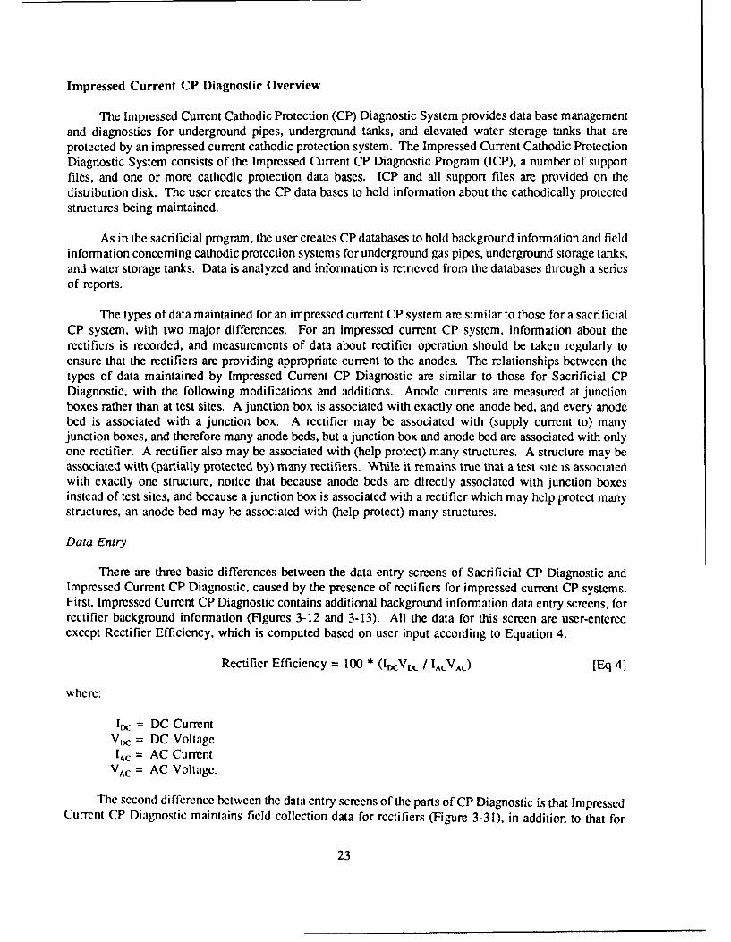
There are three basic differences between the data entry screens of Sacrificial CP Diagnostic andImpressed Current CP Diagnostic, caused by the presence of rectifiers for impressed current CP systems.First, Impressed Current CP Diagnostic contains additional background information data entry screens, forrectifier background information (Figures 3-12 and 3-13). All the data for this screen are user-enteredexcept Rectifier Efficiency, which is computed based on user input according to Equation 4:
Rectifier Efficiency = 100 * (lDVtC IACVAC) [Eq 4]
where:
I = DC CurrentVoc = DC Voltage
'AC = AC CurrentVAC = AC Voltage.
The second di fference between the data entry screens of the parts of CP Diagnostic is that ImpressedCurrent CP Diagnostic maintains field collection data for rectifiers (Figure 3-31), in addition to that for
23

test sites. This data may be used to ensure that a rectifier is continuing to operate properly. As with otherfield collection data, this information is associated with a collection date. The user may store and accessthis data to gain a history of the rectifier's operation.
A final difference between the data entry screens within CP Diagnostic is that the impressed currentprogram refers to the "on" potential and the "instant off" potential instead of "connected" and"disconnected" potentials. This difference is seen in all of the potential measurements tables.
Reports
Impressed Current CP Diagnostic provides the same reports described for Sacrificial CP Diagnostic.Some reports are slightly modified to include relevant information about rectifiers. Impressed Current CPDiagnostic also provides two additional reports that give information about rectifiers:
I. Rectifier Master Listing: This listing prints the background information for each rectifierrecorded in the data base.
2. Rectifier History Report: This report prints all field collection data recorded for each rectifier.The user may specify a range of dates for the report, which then provides only field measurementscollected during the requested range of dates.
Mode of Technology Transfer
It is anticipated that the CP Diagnostic Program will be forwarded to the Engineering and HousingSupport Center (EHSC) at Fort Belvoir, VA, for program maintenance, support, and distribution.
24

2 USER'S MANUAL FOR THE SACRIFICIAL SYSTEM
Introduction
The Sacrificial CP Diagnostic program is a user-friendly rccordkeeping and diagnostic program forcathodic protection systems that use sacrificial anodes. Background and field data is stored in severaldatabase files. The program provides information through a series of reports. The purpose of this chapteris to give detailed instructions on the operation of the program. All of the program options will beexplained. The user will be guided through the steps of preparing data for input into the program,installing the program on the computer, configuring the program, creating databases, entering backgroundand field data, and generating reports. A sample implementation specification for the sacrificial CPDiagnostic system is included in Appendix A.
Steps for Implementing and Using Sacrificial CP Diagnostic
Initial Implementation
In general, these steps will need to be performed just once, unless modifications are made to the CPsystem or to the protected structures that would change the background information.
1. Divide the CP system and protected structures into components as described below in "PreparingData for Input Into the Program."
2. Collect background data about the components as described in "Preparing Data for input Intothe Program." This will probably require a field survey to verify the information. If a field survey isdone, the first set of field data (structure-to-soil potentials, anode current outputs, and diele.tric conditions)should be collected at this time.
3. 1ihstall and configure the program as described under MAIN MENU OPTION 4 - System Utility.
4. Create databases in which to input the CP system data as described under MAIN MENUOPTION 3 - Database Administration.
5. Input background data into the databases as described under MAIN MENU OPTION 1 - DataEntry and Modifications, Submenu Option [1] - Add/Edit Structure/Test Site/Anode Background Data.
6. If the first set of field data was collected, enter it into the field collection database as describedunder MAIN MENU OPTION I - Data Entry and Modifications, Submenu Opion [2] - Add/Edit TestSite Field Collection Data. If you wish to store field collection data that was collected in the past, youmay enter it also.
7. Generate the reports of interest as described under MAIN MENU OPTION 2- Database RelatedReports.
25
Periodic Collection of Field Data
1. Generate field collection forms as described under MAIN MENU OPTION 2 - Database RelatedReports, Submenu Option I11 - Field Collection Forms.
2. Collect field data.
3. Input field data into program as described under MAIN MENU OPTION I - Data Entry andModifications, Submcnu Option (21 - Add/Edit Test Site Field Collection Data.
4. Generate the reports of interest as described under MAIN MENU OPTION 2 - Database RelatedReports.
Preparing Data for Input Into the Program
Overview
Before the program can be used, data concerning the CP system and the structure that it protectsmust be compiled. All following sections of this manual assume that this data has been compiled and isready to input into the program. Each system component will be given its own unique identificationnumber. Appendix G contains a chart which shows the relationships between system components. It willbe helpful to refer to it while you are reading this section. A record in the database will be created foreach component and data about it will be collected and entered into the record. All of the records willbe stored in the program database files. It is recommended that you obtain maps and/or drawings thatshow as much detail as possible about the system and the protected structures.
Defining the Protected Structures
Sacrificial CP Diagnostic recognizes two types of protected structures: underground pipes (such asgas distribution pipes) and underground storage tanks. A piping network is defined as a collection of"pipe sections." Each pipe section will have its own individual record in the database in which theinformation associated with it will be stored. For a system of tanks, each tank will have its ownindividual record in the database which contains the data associated with it.
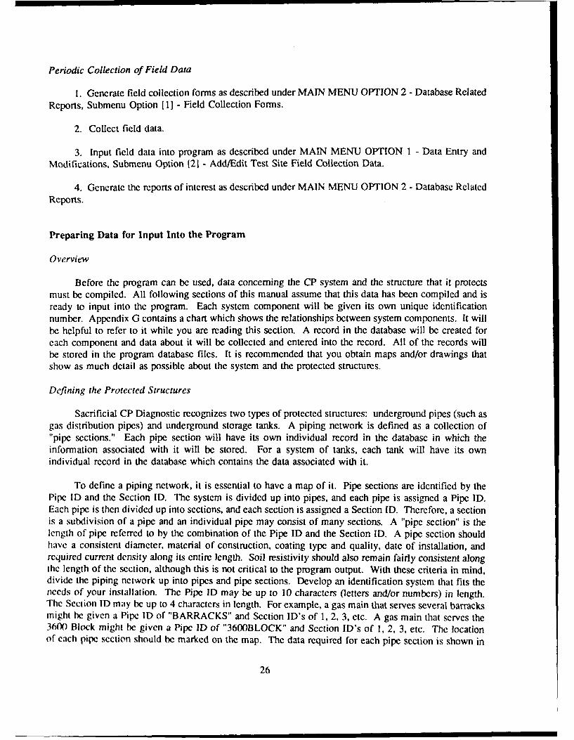
To define a piping network, it is essential to have a map of it. Pipe sections are identified by thePipe ID and the Section ID. The system is divided up into pipes, and each pipe is assigned a Pipe ID.Each pipe is then divided up into sections, and each section is assigned a Section ID. Therefore, a sectionis a subdivision of a pipe and an individual pipe may consist of many sections. A "pipe section" is thelength of pipe referred to by the combination of the Pipe ID and the Section ID. A pipe section shouldhave a consistent diameter, material of construction, coating type and quality, date of installation, andrequired current density along its entire length. Soil resistivity should also remain fairly consistent alongthe length of the section, although this is not critical to the program output. With these criteria in mind,divide the piping network up into pipes and pipe sections. Develop an identification system that fits theneeds of your installation. The Pipe ID may be up to 10 characters (etters and/or numbers) in length.The Section ID may be up to 4 characters in length. For example, a gas main that serves several barracksmight be given a Pipe ID of "BARRACKS" and Section ID's of 1, 2, 3, etc. A gas main that serves the360n) Block might be given a Pipe ID of "3600BLOCK" and Section ID's of 1, 2, 3, etc. The locationof each pipe section should be marked on the map. The data required for each pipe section is shown in
26

Figure 2-13. In addition to this data, mark and note the location of isolation joints. Isolation jointsassociated with a pipe section are numbered consecutively starting with 1. You may wish to use the PipeSection Background Data Sheet in Appendix B to help organize and compile the data. Complete one formfor each pipe section. This data is then ready to input into CP Diagnostic.
To define a system of tanks, assign a Tank ID (up to 10 characters) to each tank. Figure 2-14shows the data that is required for each tank. You may wish to use the Underground Storage TankBackground Data Sheet in Appendix B to help organize and compile the data. Complete one form foreach tank. In addition, if the piping associated with the tank is cathodically protected, an undergroundpiping record (as described in the preceding paragraph) may be created for it. This data is then ready toinput into CP Diagnostic.
Defining the Cathodic Protection System
CP Diagnostic defines the sacrificial CP system itself as a collection of "test sites." Each test siteis associated with a protected structure (pipe or tank). Each test site has one or more anodes associatedwith it.
We should first clarify the definitions of "test site," "test station," and "test point" as they will beused in this document. "Test site" is used in CP Diagnostic as a generic term for "test stations" and "testpoints." Thus, a test site may be either a "test station" or a "test point." A test station is a collection ofone or more measurement points, usually wires, that is designed for the purpose of allowing structure-to-soil potentials and/or anode current outputs to be measured. Many test stations contain a wire connectedto each nearby structure and another connected to a copper-copper-sulfate (Cu-CuSO4) half-cell in the soil.We can use these wires to measure structure-to-soil potentials without digging up the structure. The sametest station may contain terminals for anodes or groups of anodes of an anode bed that protects thestructure. At each terminal, the current flowing between the protected structure and the anodes connectedto the terminal may be measured. A test point is any other location at which we are able to take measure-ments of interest. For example, a riser for a gas service line to a house is a useful test point. Becausethe riser is above ground, we can measure the structure-to-soil potential easily. In addition, a riser shouldhave a dielectric, or isolation, joint to electrically isolate the house piping from the gas service line.Therefore, at such a test point we would also like to measure the potential across the dielectric, to ensurethat it is working properly.
To define the CP system, assign a test site ID to each test site associated with each structure in thesystem. The use of symbol conventions will make this easier. For example, test stations might be labelledTS 1, TS2, etc.; riser test points might be labelled R 1, R2, etc.; and valve test points might be labelled V 1,V2, etc. Isolation joints must also be represented as test sites since they will be tested to ensure that theyare working properly. Recall that isolation joints were numbered consecutively beginning with I whenthe protected structures were defined above. To remain consistent with this, it is suggested that thisnumber that was previously assigned to the joint should be used when inputting it into the test site datasection. To identify it as an isolation joint test site, the number might be prefaced with an I. Often,isolation joints are located at risers at which potential measurements may also be taken. In this situation,the isolation joint number might be prefaced with RI to denote it as an isolation joint that is also a risertest point. Since the test site chart allows the entry of both potentials and dielectric conditions, all of thedata for risers with isolation joints may be entered on one screen. Only riser test points without isolationjoints would be named RI, R2, etc.
27

The test sites should be marked on the system map. Each test site will contain one or morelocations at which to perform potential measurements and may contain one or more locations at which to
perform current measurements. The data required for each test site is shown in Figures 2-17 through 2-20.
Test site information requirements for pipes and tanks are identical. Information describing the test site
itself and the anode bed associated with it are needed. In addition, structure-to-soil potentials for each
potential measurement point of the test site should be collected in the field and recorded at the time the
program is implemented. Dielectric conditions (i.e., good, short, none) should be determined and recorded.Also, anode current outputs are to be collected in the field and recorded. If initial potentials and anode
currents are available (i.e., potentials and currents that were measured when the CP system was installed)
they should also be recorded. Guidance for conducting field measurements can be found in Air Fc.cc
Manual (AFM) 85-5.' 3 You may wish to use the Test Site Background Data Sheet in Appendix B to
help organize and compile the data. This data is then ready to be input into the CP Diagnostic program.
Installing Sacrificial CP Diagnostic
The Sacrificial Cathodic Protection Diagnostic System is distributed on a single disk that containsthe following files:
SCHEMAA.DBF SCHEMAW.DBFSCHEMAB.DBF SCHEMAY.DBFSCHEMAD.DBF SCHEMAZ.DBFSCHEMAI.DBF GSI.DBFSCHEMAM.DBF DB.DBFSCHEMAR.DBF SCP.EXESCHEMAT.DBF INSTSCP.BATSCHEMAU.DBF
Before doing anything with the distribution disk you should make a backup copy of the disk usingthe DOS "DISKCOPY" command. If you are not familiar with the DOS operating system or the"DISKCOPY" command, please consult your DOS manual.
As stated in Chapter 1, CP Diagnostic operates on an IBM-compatible microcomputer system with640K of Random Access Memory (RAM). A hard drive is required because of the large amounts of datastored by the program. It supports both color and monochrome monitors. The program can be configuredto support most dot matrix and laser printers.
First, check your CONFIG.SYS file to see if it contains the statement:
FILES=50
If this statement is not in the CONFIG.SYS file, you must add it. If there is a FILES statement, but thenumber is less than 50, you must change it to 50. Consult your DOS manual for assistance. If theFILES=50 statement is not in your CONFIG.SYS file, CP Diagnostic will not run properly.
' Maintcnance and Operation of Cathodic Protection Systems, Air Force Manual (AFM) 85-5 (Headquarters. U.S. Air Force,1982).
28

IMPORTANT: In the installation procedure that follows:
A: refers to the letter designation of the floppy disk drive from which you are installing theprogram.
C: refers to the letter designation of the hard drive on which you are installing the program.
Your disk drives may or may not be designated by the letters A: and C:. If not, substitute the appropriateletters for A: and C:.
To install the Sacrificial Cathodic Protection Diagnostic System on a hard disk, place the backupdisk into the floppy disk drive of your computer. You will see the DOS prompt "C:>" to which you willenter the following command "A:". The DOS prompt will now read "A:>" to which you will respond"INSTSCP A: C:". Your screen should show:
C:> A:A:> INSTSCP A: C:
(Note: the C:> and A:> portions of the commands are DOS prompts and are not user-entered.) The"INSTSCP" program creates a directory named SCP on the hard disk and copies all the files needed torun the Sacrificial Cathodic Protection Diagnostic System to the SCP directory. After the "INSTSCP"program has finished, the system is ready to use. Remember to store the distribution and back-up disksin a safe place.
Starting the Sacrificial CP Diagnostic System
Before starting the Sacrificial Cathodic Protection Diagnostic System, you need to access thedirectory and drive containing SCP and its support files. If you have just installed the program, you arealready in the correct directory. If not, you will need to change to the SCP directory. For example, ifthe Sacrificial Cathodic Protection Diagnostic System was installed on drive C, the following commandsaccess the drive and directory containing SCP.
A:> C:C:> CD\SCP
(Note: The A:> and the C:> are DOS prompts and are not user-entered commands.) The programis then started by entering the command SCP at the DOS prompt. As the program starts, it displays anopening screen that lists the program authors. Press any key to continue. After the opening screen iscleared the program displays either the MAIN MENU screen or a MISSING FILE(S) error screen. If theerror screen appears, make a note of the missing file(s), copy them from your backup disk, and restart theprogram.
Diagram of Program Flow
To assist you with navigating throughout the Sacrificial CP Diagnostic Program, a diagram showingthe program flow is included in Appendix C. This diagram consists of five sheets labelled A through E.All menus and menu options in the diagrams are cross-referenced with their descriptions in the main text
29

of this manual. Cross references are given in brackets { } and consist of a letter and a number. The letterrefers to the sheet of the diagram on which the option or menu appears. For example, in the text below,the cross-reference (Al) appears after the title "Main Menu Overview." To locate this in the diagram,turn to Appendix C and find sheet A. Block (Al) is located at the top of sheet A. By using the diagramsand the cross-references, you can easily determine your location in the program at any time.
General Rules for Operating the Menus
CP Diagnostic is a menu-driven, user-friendly program. There are two basic rules that apply to theoperation of ALL menus throughout the program.
1. Menu options are selected by (1) typing the number of the option, or (2) moving the selectionbar to the desired option and pressing <Enter>. Once an option is selected, the program either executesthe option or displays a message about its failure to perform the option.
2. The <Esc> key can be used to move back to the previous menu or program screen.
About Passwords
Certain sections of the CP Diagnostic program are password-protected to reduce the chance ofunauthorized persons editing or deleting your data. There are three passwords which you may set: theadd/edit password, the delete password, and the general system information password. The add/editpassword is used to control access to the "Add/ Edit Structure/ Test Site/ Anode Data" option and the"Add/ Edit Test Site Field Collection Data" options of the ADD/ MODIFY/ DELETE menu. The deletepassword is used to control access to all options which allow deletion of structures, test sites, or entiredatabases. The general system information password is used to control access to the "System Utility"option of the MAIN MENU. Procedures for setting these passwords will be discussed in the "SystemUtility" section.
A particular password only needs to be entered once during a program run. For example, once youenter your delete password, you will be allowed access to all "delete" options until you exit the program.You will not be prompted for the password every time you attempt to access a "delete" option, even ifyou have performed other program operations in the meantime. After you exit the program and thenrestart it, you will be prompted for the passwords again.
Most of the instructions for each program option described in this manual are written with theassumption that the password necessary to access the option has not yet been entered. If you have, in fact,entered the password during your current working session, disregard the references to the passwordscreens.
MAIN MENU Overview [Al)
The MAIN MENU screen (Figure 2-1) illustrates a number of features of SCP's user interface. Themenu displays an informative header across the top of the screen containing three information boxes: theFile Box, the Banner Box, and the Version Box. The File Box (top left of the screen) displays the nameof the active Cathodic Protection data base. The Banner Box (top middle of the screen) displays the name
30

of the program, the current location in the program, and a short description of the active CP data base.The program Version Box (top right of the screen) displays SCP's version number. The current date andtime are displayed below the file and version boxes to complete the program's header. On a colormonitor, the color of the header provides the following additional information:
" RED All Error Screens" WHITE The MAIN MENU and Secondary Menu Screens" CYAN All Other Menu or Option Screens.
The Sacrificial Cathodic Protection Diagnostic Program is operated from the MAIN MENU (Figure2-1). The MAIN MENU has five options. The following sections of this manual describe each of theprogram's MAIN MENU and secondary menu options in detail.
MAIN MENU Option I (Data Entry & Modification) and Option 2 (Data Base-Related Reports) areordered before Options 3 and 4 in the MAIN MENU because they are used most often. Most of yourwork in the Sacrificial Cathodic Protection Diagnostic System will be done through Options I and 2.However, there are several procedures which you must perform initially when using CP Diagnostic forthe first time. You must configure the program for your hardware using MAIN MENU Option 4. Youmust then create and/or select a database for use using MAIN MENU Option 3. Thus, MAIN MENUOption 4 will be discussed first, followed by Option 3. Options 1 and 2 will be discussed last.
MAIN MENU Option 4 - System Utility {A81
This option is used to configure CP Diagnostic for your hardware and to set passwords (Figure 2-2).If passwords have not yet been set, the General System Information screen (Figure 2-2) 1 A9} will appearimmediately after this option is selected. If passwords have been set, you will be prompted to enter yourgeneral system information password. Type your password and press <Enter>. Your password will notbe displayed on the screen as you type it.
File Selected Cathodic Protection System M icro cr DiagnosticsHIM~ MENUI
FTHILEV Ft. RIlcy Field Test Verslon 1.1
03,o1ZI91 16:00:56
| I~iPl titii l IlII IKI
Z Database Belated Reports.3 Database Administration.I System Utility.0 Exit C? Diagnostics.
OPTIcO
Figure 2-1. MAIN MENU (sacrificial).
31

File SelectedCatitodic Protectiov" System icoCDigstsFila I SYSTEM IFOWTION I
FTRILEY Ft. Riley Field Test Uersiom 1.1
M/L1/91 08:57:34
Name U. S. Army Corps of EngineersAddress P. 0. Box 4005City Champaign State IL Zip 618Z4-400S
Password to access ADD/EDIT Module ftPassword to access DELETE Modu lc DPassword to access GSI Module Z
Printer codes: 10 epi 27 38 107 48 83Printer codes: 17 cpi ZV 35 107 50 83
(in decimal ASCII)
Use Color Monitor settings
Figure 2-2. GENERAL SYSTEM INFORMATION screen (sacrificial).
Enter your name (or the installation's name) and address in the top portion of the screen.
As discussed previously, each of the three kinds of data manipulation--add/edit data, delete data, andedit general system information (system utility)-has its own password. Passwords may be up to sixcharacters in length. Enter the desired passwords in the appropriate location. Once you enter a passwordfor the GSI (system utility) module, you will not be able to access this screen again without it. Thus, itis critical that you commit the passwords to memory or write them down.
The printer codes are needed to configure CP Diagnostic for your printer so that the reports printcorrectly. The printer codes are entered in decimal ASCII. Consult your printer manual to determine thecodes needed to switch your printer to compressed mode and enter them as the 17-characters-per-inchcodes. Next, determine the codes needed to cancel compressed mode and enter these as the 10-character-per-inch codes.
The monitor setting controls whether or not CP Diagnostic screens appear in color. If you have acolor monitor, enter "Y" after the "Use Color Monitor Settings?" prompt. If you do not have a colormonitor, enter "N".
CP Diagnostic is now configured for your hardware. These settings will be stored by the program.You will only need to repeat this setup procedure if you wish to change the passwords or if you use theprogram with a different printer or a different monitor type. To return to the MAIN MENU, hit <Esc>or press <Enter> on the "Use Color Monitor Settings" field.
MAIN MENU Option 3 - Data Base Administration {A6}
The Data Base Administration option of the MAIN MENU is used to manipulate the database filesthat are stored by CP Diagnostic. Databases can be added (created), selected for use, deleted, andreindexed using this option. When the Data Base Administration option is selected, the DATA BASEADMINISTRATION MENU screen (Figure 2-3) (A7) will appear.
32

[ie 1eece Cath~odic Protect ion System Micro CF Diagnostics
File~elcted IDATABASE ADIIISTRATIOM MENFTRILEV Ft. Riley Field Test Uersion 1.1
18/Z5/51 1S:58:59
2 Delete a Database.3 Relidex Selected Database.4 Register an Existing Database.0 Return to Main henu.
Figure 2-3. DATABASE ADMINISTRATION MENU screen (sacrificial).
DATA BASE ADMINISTRATION MENU Option I - Add/Select a Data Base [El)
This option allows you to (1) add (create) a new database, or (2) select an existing database for use.This option also alerts you if files are missing from a database that you are attempting to select. Note thatif you are using CP Diagnostic for the first time, you will need to add a database before entering any data.
The Sacrificial Cathodic Protection Diagnostic System can maintain many separate CP data bases.The amount of information stored is limited only by the available space on the hard disk. You may wishto store all of your data in one database, or you may wish to divide it up into several databases. Storingdata in more than one database is advantageous when you have a large amount of data or when you aremaintaining data for more than one installation. Each CP data base is given a one- to seven-charactername within the Sacrificial Cathodic Protection Diagnostic Program. The program creates a series of diskfiles to store the information for each of the databases that is created. The names of the disk files consistof the one- to seven-character database name plus a single character. For example, the disk files for theCP database HOOD would have the following names:
HOODA.DBF Anode current background data for the CP database HOODHOODB.DBF Anode current field data for the CP database HOODHOODD.DBF Test site field data for the CP database HOODHOODI.DBF Isolation joint locations for the CP database HOODHOODM.DBF Pipe section background data for the CP database HOODHOODR.DBF Repair information for the CP database HOODHOODT.DBF Test site and anode background data for the CP database HOODHOODU.DBF Underground storage tank background data for the CP database HOODHOODW.DBF Test site wire background data for the CP database HOODHOODY.DBF Test site field comments for the CP database HOODHOODZ.DBF Anode current field comments for the CP database HOOD
33

When you choose the Add/Select a Data Base option from the Data Base Administration Menu, the
SELECTING A DATA BASE screen will appear (Figure 2-4). This screen lists all the Cathodic Protec-
tion data bases (if any) that have been entered into the Sacrificial Cathodic Protection Diagnostic System.
To ADD (Create) a New Database: {E2) As stated above, you will need to do this if you are using
the program for the first time. To create a CP data base, simply type a one- to seven-character name for
it at the "Database" prompt of the SELECTING A DATA BASE screen and press <Enter>. IMPOR-
TANT. The database name must not include any spaces. For example, TEST DB would not be an
acceptable database name. In addition, the database name must begin with a letter. The name must be
different from the other existing database names. When a database name is entered that does not alreIdy
exist in the program, the CREATING A DATA BASE screen appears. This screen asks you if you want
to create a new CP data base. If you answer no <N>, you are returned to the DATABASE ADMIN-
STRATION MENU, and the currently selected data base is not changed. If you answer yes <Y>, a new
CP data base (with the name that you have specified) is added to the system. Before the new data base
is created, it must be given a description. The program prompts for a short (up to 20-character)
description of the data base. The data base files are then created, the data base is automatically selected,
and you are returned to the DATABASE ADMININSTRATION MENU.
To SELECT an Existing Database for Use: {E3) All CP data bases that have been previously
entered into the system are listed in the "selecting a database" screen. If there are many CP data bases
on the disk, the list may contain multiple pages. The <PgUp> and <PgDn> keys may be used to pagethrough multiple-page listings of Cathodic Protection data base files. To select one of the listed databasesfor use, type its name at the "Database" prompt and press <Enter>. To exit the SELECTING A DATABASE screen without changing the currently active CP data base, use <Esc>. After the data base is
selected, its name and description are placed in the program's header, and you are returned to theDATABASE ADMINSTRATION MENU.
File SelectedCathvodic Frotection system MlicroCDigstc
File Selected SELECTING A DATABASE Dinots
FTRILEY FtI. Riley Field Test j Version 1.1
03,12/I91 16:04:07
Database:
TEST test dbFTRILEY Ft. Riley Field Test
(PgUp) <PgDn) preuious / next page (ESC) quit
Figure 2-4. SELECTING A DATABASE screen (sacrificial).
34

Note that if this is not the first time you have used the program, the data base that was in use thelast time the program was run remains active when the program is started again and does not need to be
activated with the Data Base Administration option.
If Some Files Are Missing from the Selected Database: Occasionally all or some of the disk filesof a Cathodic Protection data base may be missing. This can occur, for example, if you delete the filesusing DOS and forget to remove the CP data base name from SCP. The MISSING FILE(S) Screen alsoappears when the program is started using an incomplete or missing data base. When this occurs, theMISSING FILE(S) Screen (Figure 2-5) appears. To use the incomplete data base, note the names ofthe missing file(s). Press any key to return to the DATABASE ADMINISTRATION MENU. LeaveSCP, copy the file(s) from a backup disk, and restart SCP.
DATA BASE ADMINISTRATION MENU Option 2 - Delete a Data Base {E4}
The Delete a Database o. .,on allows you to remove data base files from your hard drive. After youselect this option, enter your "delete" password when prompted. The SELECTING A DATABASE screenwill appear. Select a database to delete and type its name at the prompt. Next, the DELETE A DATABASE screen will appear (Figure 2-6). It will display the name of the data base that you have selectedin the lower left hand comer of the screen and will ask you if you really wish to delete all the recordsassociated with this data base.
If you do not wish to delete the selected database, press <N> or <Enter> at the prompt to return tothe DATABASE ADMINISTRATION MENU.
If you wish to delete all records of the data base from your hard disk and the SCP program, pressthe <Y> at the prompt. It is recommended that you make a backup of the files on a disk beforeproceeding with the delete option. DELETED DATA BASE FILES CANNOT BE RECALLED.
After the files are deleted, press any key when prompted to return to the DATABASE ADMINIS-TRATION MENU.
File Selected Cathodic Protection System Micero CP DiagnosticsMISSING FILMXS)
(none) No File Selected Version 1.1
0213,91 IS!29:53
Database not found on working disk.Flease copu fron your backup diskette.
TEST?.DBF FOUNDTESTN.DBF FOUNDTESrT. DBF FOUNDTEST!. DRF FOUNDTEST . DDF FOUNDTESTW. DBF FOUDTESTY. DBF FOUNDTESrA.DBF NOT FOUINDTESTB.DBF FOUNDTESTZ. DF FOUND
Press any key to return to Main Menu
Figure 2-5. MISSING FILES screen (sacrificial).
35

ril Se lCcted cathodic Potectoil uste. Plicro Cr Diagnostics
e DELETE A DATABASE
TEST test dt Uers ion 1.1
6Z,'i3/1 15:31:38
i Delete Database TEST This option DELETES All Recordsfrom the Selected database.
H
(VA) Is this what gnu wish to do?
Figure 2-6. DELETE A DATABASE screen (sacrificial).
DATA BASE ADMINISTRATION MENU Option 3 - Re-Index a Data Base (ES)
This option will create new index files for the current data base. The index is used in searching filesfor particular records and must exist in order for the program to operate properly. Re-indexing data basefiles from time to time will help the system run faster. If, over a period of time, many operations havebeen performed such as adding or deleting records, re-indexing will help speed your work by "cleaningup" the index. This option should also be used if the index files are accidentally erased.
You will be asked if you want to rebuild the index for the currently selected data base (Figure 2-7).If this is what you want to do, press <Y> for YES. After indexing is complete, press any key to returnto the DATABASE ADMINISTRATION MENU. If this is not what you want to do, press <N> for NO.The program will return to the DATA BASE ADMINISTRATION menu.
DATABASE ADMINISTRATION MENU Option 4 - Register on Existing Database [E6)
It is possible that existing CP data bases will not be listed in the SELECTING A DATA BASEScreen's data base list. For example, this occurs if you install a new version of SCP on a computer withexisting CP data bases. Before these data bases can be selected for use, they must be "registered" withthe program so that it recognizes their existence. To "register" an existing data base with the system, typeits name at the "Database" prompt of the SELECTING A DATA BASE Screen. The MISSING FILE(S)Screen (Figure 2-5) will list any files of the data base that may be missing. If any of the data base filesare missing, note their names, exit the program, and copy them from a backup disk, then restart the SCPprogram, and select the data base. If no files are missing, the MISSING FILE(S) Screen is supplementedwith the message that the data base is being added to the system. You are then prompted to enter a newdescription for the data base. After you enter the description, the new database becomes the currentdatabase in use, and you are returned to the MAIN MENU.
DATA BASE ADMINISTRATION MENU Option 0 - Return to Main Menu (E7}
This option returns you to the Main Menu of Sacrificial CP Diagnostic.
36

FieSletdCathodic Protectiton System. Mincro cr iagnosticsFile~elcted I UDI I"DZC TILES
FTRILEV Ft. Rilenj Field Test Version 1.1
03/1Z./91 16:65:18
This will rebuild the Index for the currently selected database.Do you wish to continue?
Figure 2-7. REBUILD INDEX FILES screen (sacrificial).
MAIN MENU Option 1 -- Data Entry and Modification (A2}
The Data Entry and Modification option of the MAIN MENU is used to create and update informa-tion about cathodic protection systems in the currently active CP data base. A CP data base must beactive (selected) before this option can be used. If no CP data base is active when you select the DataEntry and Modification Option, the SELECTING A DATABASE screen will appear. Type the name ofthe database that you wish to work with at the prompt. If you attempt to exit the SELECTING ADATABASE screen before typing a database name, the program displays the error message:
"You Must Have A Data Base In Use!"
You will not be allowed to exit this screen without selecting a database.
After you have selected the Data Entry & Modification option and have an active database, the AD-D/MODIFY/DELETE MENU (A3) will appear. You will notice that the ADD/ MODIFY/ DELETEMENU Screen displays five options (Figure 2-8). Select the desired option in the usual manner.
General Rules for Data Entry and Modification
CP system data is entered via a series of screens, each of which contains a series of promptsfollowed by blank spaces, or "fields," in which the data is to be entered. There are several general rulesthat apply throughout all of the Data Entry and Modification screens.
1. Enter data in each field by typing your response and pressing the <Enter> key. The cursor thenmoves to the next field.
37

file Selected I Cathodic Protection System Micro Cr DiagnosticsS ADDflODIFY/DELETE IMi
FTRILEY Ft. Rileg Field Test kUersion 1.1
8328"l 15:03:21
2 ADD/IDIT Test Site Field Collection Data3 DELETE Structure/Test SiteAnode Data4 DELETE Test Site/Anode Data Onlg0 Exit to Main Menu.
Figure 2-8. ADD/MODIFY/DELETE MENU screen (sacrificial).
2. If the information for a field is not available, press <Enter> to bypass that field and move theprompt to the next field. The former field will be left blank. If the information for that field becomesavailable at a later date, it may be entered into the program at that time.
3. The backspace and delete keys may be used to correct mistakes in data entry. The backspacekey will erase the character immediately to the left of the cursor. The delete key will erase the characterat the cursor.
4. The insert key may be used to toggle between insert mode and typeover mode.
5. The left and right arrow keys may be us-J to move the cursor within the field that you arecurrently editing.
6. The up arrow key may be used to move to the field above the one you are currently in and thedown arrow key may be used to move to the field below it.
ADD/MODIFY/DELETE MENU Option 1 - ADD/EDIT Structure/Test Site/Anode Data (BI)
This option allows you " enter new structures, test sites, and anode bed,. -ith the associated data,into the system, and allows you to edit data for existing structures, test sites, and anode beds.
After you choose this option, the ENTER ADD/EDIT PASSWORD screen (Figure 2-9) will appear.At the prompt, type your add/edit password and press <Enter>. The password will not be displayed onthe screen as you type it.
After you enter the password, the STRUCTURE TYPE SPECIFICATION screen (Figure 2-10) willappear. You will be asked whether you are editing pipe section records or tank records. Type yourresponse at the prompt. The appropriate STRUCTURE IDENTIFICATION screen will appear. Figure2-1 1 shows the pipe section identification screen. Figure 2-12 shows the tank identification screen.
38

File Selected | Cathodic Protection System Micro CF Diagnostics]HTER ADD/ED PASSWORD
FTRILEY Ft. Riley Field Test Uersion 1.1
83/I Z/91 16:07:48
Enter Password
Figure 2-9. ENTER ADD/EDIT PASSWORDscreen (sacrificial).
File Selected Cathodic Protection System Micro CF DiagnosticsSTUCTUIz TYPE SPECITICATIo10
?NAMS Tank Database Version 1.1
03,Z/91 15:45:99
Do you wish to work with a pipe section (P)or an underground storage tank (T)?
Please enter T or P: P
Figure 2-10. STRUCTURE TYPE SPECIFICATION
screen (sacrificial).
39

File CJ Seece Cathodic Protectioni Sysatem Micro CF DiagnosticsII IPFIE SECTION IDENTIFICATIOIN
FRLYFt. Rileyj Field Test Version 1.1
03/1Z/931 16:66 :15
Enter PIFE ID:Enter SECT ID:
ST24 CHT31ST24 MARY
<Pgqp) <PgDn> previous / next page <ESC) quit
Figure 2-11. PIPE SECTION IDENTIFICATION screen(sacrificial).
File Selected Cathodic Protectin Sysitem Micro CF DiagnosticsTANX IDENITIFICATIOlN
TANKS Tank Database f Version 1.1
03.2Z91 15:46:25
Enter TANX ID:
01
<PgUp) <FgDn> previous / next page <ESC) quit
Figure 2-12. TANK IDENTIFICATION screen (sacrificial).
40

If you wish to edit an existing record, consult the list of structure ID's shown on the screen. This
is a complete list of the identification numbers of previously entered structures. The <PgUp> and <PgDn>
keys are used to scroll through the pages of the list. To select an existing pipe section record for editing,
type the PIPE ID (up to 10 characters) exactly as it appears in the list at the prompt and press the <enter>
key to move the prompt to SECT ID. Enter the four-character section identification number at the prompt
and press <Enter>. To select an existing tank record for editing, enter the TANK ID (up to 10 characters)
exactly as it appears in the list of existing structures.
If you wish to create a new record, type a new structure ID at the prompt, following the procedures
given in the preceding paragraph for entering structure ID's. The program automatically creates a new
record when a structure ID is entered that does not already exist in the program (i.e., does not appear on
the list).
After you have entered the Structure ID, the ADD/EDIT BACKGROUND DATA screen (Figure
2-13 for pipes; Figure 2-14 for tanks) will appear. The STRUCTURE/TEST SITE/ANODE DATA
submenu (CI) is located at the bottom of the screen and displays a list of four options from which you
may choose.
STRUCTURE/ TEST SITE/ ANODE SUBMENU Option I - Add/Edit Background Data. (C21
You may add or edit background information about the structure that you have selected by choosing
option 1 of the submenu. This is the information that you collected on the Pipe Background Data Sheets
or the Underground Tank Background Data Sheets from Appendix B. Add or edit background information
by typing the appropriate information at the corresponding prompt on the screen and pressing <Enter> to
move to the next prompt. Note that Surface Area and Total Current Required are automatically calculatedby the program.
file Selected Cathodic Protection System Iicro CP DiagnosticsADD/EDIT BACIGRONiD DATA
FTHILE Ft. lle Field Test Version 1.1
03-28.91 15:06:17
Pipe ID ST24 Coating Type TAPE/ TARSection Id CHII Coating Quality (ohms) 0LAcatlon From 2" LATERAL Coating Efficienc (y) 30.00Location To I" lATERAL Soft Resistivity (ohm-cn) 3100.Date Pipe Installed 02?.02./4 Section Length (ft) 1200.00Date CP Activated 01-0184 Section Diameter Cin) 6.00CP Installer JPI Req. Carrevt DLesit 9 (WA/sq.ft) 1.00
Surface Area (sq.ft) 1884.00
Do Isolation Joint: Exist? T Total Current Required (A) 8.19
2 ADD/EDIT Test Site Background Data3 ADD/EDIT Repair Data0 Exit to AdA/Delete Menu
Figure 2-13. ADD/EDIT PIPE BACKGROUNDDATA screen (sacrificial).
41

Fili Selected Cathodic Protcction System Micro CF DiagnosticslDdD/EDIT D XAiOUH DATA
HOTPHT R Gray AAF-Hot Pt RI" Vers ion 1.1
18/Z9/9 1 11 :ee:56
Tank ID HOTPOINTI Coating TypeTank Type UIDERGROi) Coating Quality (o") 0Location ?AMX FARMI-UEST SIDE Coating Efficiency (;) 0.00Date Tank Installed 1011AIS Soil Resistiuity (ohm-cm) 3600Tank Material DBL. WALL STEE Tank Length (ft) 60.90Tank Contents JP-6 Tank Diameter (ft) iZ.00Date CP Actiuated / / Req. Current Density C.afsq.ft) 0.00CP Installer WINU Surface Area (sq.ft) 2486.88
Total Current Required (A) 0.00Do Isolation Joints Exist7 Y
Z ADDEDIT Test Site Background Data
3 ADD/EDIT Repair Data0 Exit to Add/Delete Menu
Figure 2-14. ADD/EDIT UNDERGROUND TANK BACKGROUNDDATA screen (sacrificial).
To answer the question "Do Isolation Joints Exist?", press either <Y> for Yes or <N> for No. If<Y> is pressed a window will appear at the bottom of the ADD/EDIT BACKGROUND DATA SCREENasking for the location of the identified isolation joints (Figure 2-15). Enter the location description andpress <return>. You may enter as many isolation locations as desired. Use the up/down arrow keys onyour keyboard to page through the entered isolation joint locations. When finished, press <Esc> to returnto the STRUCTUREITEST SITE/ANODE DATA submenu.
STRUCTURE/rEST SITE/ANODE SUBMENU Option 2 - Add/Edit Test Site Background Data.{C3} This option allows you to add or modify test site and anode bed background data, initial potentials,initial dielectric conditions, and initial anode currents for the test sites that are associated with the currentlyselected structure. This option also allows you to add new test sites for the currently selected structure.For a detailed explanation of test sites, see the section in this chapter entitled "Defining the CathodicProtection System."
When this option is selected, the SCP program will display the TEST SITE IDENTIFICATIONscreen (Figure 2-16). The TEST SITE IDENTIFICATION screen prompts you to enter a Test Site IDnumber.
If you wish to edit an existing record, consult the list of test site ID's shown on the screen. Thisis a complete list of the identification numbers of previously entered test sites for the currently selectedstructure. The <PgUp> and <PgDn> keys are used to scroll through the pages of the list. To select anexisting test site record for editing, type the Test Site ID exactly as it appears in the list at the prompt andpress the <Enter> key.
If you wish to create a new test site for the currently selected structure, type a new test site ID atthe prompt. The program automatically creates a new record when a Test Site ID is entered that does notalready exist in the program (i.e., does not appear on the list).
42

File Selected Cathodic Protection System icro CF DiagnosticsI AbDDEDIT DA#CXGROUII DATA
FTRILEY Ft. Rileg Field Test Uersion 1.1
83/1"/1 09:4?7:51
Pipe ID STZI Coating TypeSection Id CHTR Coating Quality (alms)Location Fro m Coating ErFtciency (0Location To Soil Resistivity (ohN-cM)Date Pipe Installed Section Length (ft)Date CP Activated Section Diameter (in)CP Instazller Req. Current Density CmWvsq.ft)
Surface Area (sq.ft) 1864.00
Number Isolation Location
1 I 5I~t Il 5
t I select - add location <ENTER) modify location<(gUp> <PgDn> previous / next page <ESC> quit
Figure 2-15. ADD/EDIT BACKGROUND DATA(isolation joints-sacrificial).
File Selected Cathodic Protection System IMicro CF DiagnosticsTEST SITE IDENTIFICATIONl
FTHILE! Ft. illey Field Test Version 1.1
10/29/,91 1:04:5?7
Enter Test Site ID:
OOIGAS02GGAS03CHGAS4OGAS05CHGAS
(PgUp) (PgDn> previous / next page <ESC> quit
Figure 2-16. TEST SITE IDENTIFICATIONscreen (sacrificial).
43
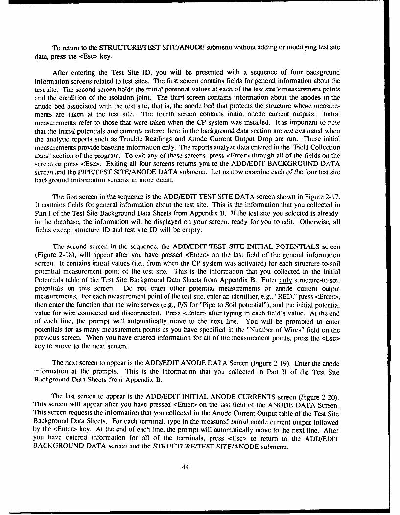
To return to the STRUCTURE/TEST SITE/ANODE submenu without adding or modifying test sitedata, press the <Esc> key.
After entering the Test Site ID, you will be presented with a sequence of four backgroundinformation screens related to test sites. The first screen contains fields for general information about thetest site. The second screen holds the initial potential values at each of the test site's measurement pointsand the condition of the isolation joint. The third screen contains information about the anodes in theanode bed associated with the test site, that is, the anode bed that protects the structure whose measure-ments are taken at the test site. The fourth screen contains initial anode current outputs. Initialmeasurements refer to those that were taken when the CP system was installed. It is important to r 'tethat the initial potentials and currents entered here in the background data section are not evaluated whenthe analytic reports such as Trouble Readings and Anode Current Output Drop are run. These initialmeasurements provide baseline information only. The reports analyze data entered in the "Field CollectionData" section of the program. To exit any of these screens, press <Enter> through all of the fields on thescreen or press <Esc>. Exiting all four screens returns you to the ADD/EDIT BACKGROUND DATAscreen and the PIPE/TEST SITE/ANODE DATA submenu. Let us now examine each of the four test sitebackground information screens in more detail.
The first screen in the sequence is the ADD/EDIT TEST SITE DATA screen shown in Figure 2-17.It contains fields for general information about the test site. This is the information that you collected inPart I of the Test Site Background Data Sheets from Appendix B. If the test site you selected is alreadyin the database, the information will be displayed on your screen, ready for you to edit. Otherwise, allficlds except structure ID and test site ID will be empty.
The second screen in the sequence, the ADD/EDIT TEST SITE INITIAL POTENTIALS screen(Figure 2-18), will appear after you have pressed <Enter> on the last field of the general informationscreen. It contains initial values (i.e., from when the CP system was activated) for each structure-to-soilpotential measurement point of the test site. This is the information that you collected in the InitialPotentials table of the Test Site Background Data Sheets from Appendix B. Enter only structure-to-soilpotentials on this screen. Do not enter other potential measurements or anode current outputmeasurements. For each measurement point of the test site, enter an identifier, e.g., "RED," press <Enter>,then enter the function that the wire serves (e.g., P/S for "Pipe to Soil potential"), and the initial potentialvalue for wire connected and disconnected. Press <Enter> after typing in each field's value. At the endof each line, the prompt will automatically move to the next line. You will be prompted to enterpotentials for as many measurement points as you have specified in the "Number of Wires" field on theprevious screen. When you have entered information for all of the measurement points, press the <Esc>key to move to the next screen.
The next screen to appear is the ADD/EDIT ANODE DATA Screen (Figure 2-19). Enter the anodeinformation at the prompts. This is the information that you collected in Part II of the Test SiteBackground Data Sheets from Appendix B.
The last screen to appear is the ADD/EDIT INITIAL ANODE CURRENTS screen (Figure 2-20).This screen will appear after you have pressed <Enter> on the last field of the ANODE DATA Screen.This screen requests the information that you collected in the Anode Current Output table of the Test SiteBackground Data Sheets. For each terminal, type in the measured initial anode current output followedby the <Enter> key. At the end of each line, the prompt will automatically move to the next line. Afteryou have entered information for all of the terminals, press <Esc> to return to the ADD/EDITBACKGROUND DATA screen and the STRUCTURE/TEST SITE/ANODE submenu.
44

File Slected Cathodic Protection System I Micro C? DiagnosticsI DD/EDIT TEST SITE DATA
FTRILEV Ft. RiLeq Field Test Uersion 1.1
e4,11/91 10:36:28
Pipe Identification STZ4 OITRTest Site ID OI0CGAS
Location COINER BULLARD & NORIMNYDescription GENERICUedor GOODALLSurface or Flush Mounted? (SeF]FTools Required MNatural Potential (uolts) 0.622Intl. Bond Resistance (ohms) 9.00Does Interfereice Exist? NShunt Resistor Value (ohms) 8.06e6Humber of Mires 1Coments
Figure 2-17. ADD/EDIT TEST SITE DATA screen (sacrificial).
File Selected Cathodic Protection System Miiicro CF DiagnosticsADD/EDIT TEST SITE DATA
MTIILEY Ft. 111CY Field Test VJersion 1.1
03/22/91 16:31:80
Test Site ID: 1CIGAS
Measurement Point Initial Potentials (IV)
MO. IDENTIFIER FUNCT ION CONNECTED DISOINECTED DIELECTRIC
t I select t add mire <EITER) modify wire
<PUp) (?gDn> preulous / next page <ESC) quit
Figure 2-18. ADD/EDIT TEST SITE INITIALPOTENTIALS screen (sacrificial).
45

File Selected I Cathodic Protection System Micro CF Diagnostics)ADD.EDIT ANODE DATA
FIRILEY Ft. Riley Field Test Uersion 1.1
63/1/31 10: 16:46
Test Station Id
AnodeTypeDesign Life (yjrs)Anmode Mqaterial Anode spacing (ft) /
Anode Diameter (in) Structure to Anode
Anode Length (in) Distance (ft)Anode Weight (ib) DirectionNumber of; Cable Gauge
Anodes * Cable Insulation TypeAnode Current Output Termina]s
Figure 2-19. ADD/EDIT ANODE DATA screen(sacrificial).
File Selected Cathodic Protection System Mlicro Cr DiagnosticsADD/-EDIT ANODE DATA e: esoI.
FIRILEY Ft. Riley Field Test Version 1.1
03,19/91 10:16:46
Test Station/roint ID: 91CIIAS
initial Current Output
TERMINAL NUBER ANODE CURRENT OUTPUT (Amps)
I I select / edit anode <ENTER) modify anode<PgUp> <YgDn) previous / next page <ESC) quit
Figure 2-20. ANODE CURRENT OUTPUT screen (sacrificial).
46

STRUCTURE/TEST SITE/ANODE SUBMENU Option 3 - Add/Edit Repair Data. {C4} To enterinformation regarding repairs on the currently selected cathodically protected structure, select submenuoption 3 at the bottom of the ADD/EDIT BACKGROUND DATA screen. A pop-up screen will appearat the bottom of the ADD/EDIT BACKGROUND DATA screen (Figure 2-21). Enter the repair date atthe prompt. If you wish to use the current (default) date that is displayed, simply hit <Enter>. Enter therepair information for the selected structure as prompted. After you enter all of the repair information,the program will remove the pop-up screen and replace it with the ADD/EDIT STRUCTURE/TESTSITE/ANODE DATA submenu.
STRUCTUREITEST SITE/ANODE SUBMENU Option 0 - Exit to Add/Delete Menu. {C5) Thisoption allows you to exit from the ADD/EDIT BACKGROUND DATA screen. You will first exit to theSTRUCTURE IDENTIFICATION screen. If you wish to add or edit background data for a differentstructure, type its ID as described earlier. If you do not wish to work with another structure, hit <Esc>.This will return you to the ADD/MODIFY/DELETE MENU.
ADD/MODIFY/DELETE MENU Option 2 - ADD/EDIT Test Site Field Collection Data {B2)
The ADD/EDIT Test Site Field Collection Data option allows you to enter potentials and anode cur-rents each time they are gathered in the field. These are the measurements that will be evaluated by theanalytic reports. When you select this option, you will be asked to enter your add/ edit password if youhave not already done so. After you enter the password, the STRUCTURE TYPE SPECIFICATIONscreen (Figure 2-10) will appear. You will be asked whether you are editing pipe section records (P) ortank records (T). Type your response at the prompt. The appropriate STRUCTURE IDENTIFICATIONscreen will appear. Select the structure with which you wish to work in the usual manner. Next, theTEST SITE IDENTIFICATION screen will appear. Enter the ID of the test site with which you wish towork at the prompt.
NOTE: The Test Site ID must already exist; you will not be able to proceed further in this opera-tion if the appropriate background information corresponding to this Test Site ID has not already been
File Selected Cathodic Protection Sustem M icro CF DiagnosticsAD,/EDIT BAC1GROUN DATA
FIRlLE Ft. Mi .e Field Test I Version 1.1
03,12,91 16:15:I9
Pipe ID 3724 Coating Type TArE., TARSection Id CHTR Coating Quality (ohms) 0Location From Z" LATERAL Coating Efficiency (.) 50.00Location To 4" LATERAL Solt Resistivity (ohm-cm) 0.Date Pipe Installed 01?O-044 Section Length (ft) 1200.00Date CP Activated 03401.84 Section Diameter (in) 6.00CP Installer J]PH Req. Current Density (mA/sq.ft) 1.00
Enter Date of RepairFAILURE
NAM REPAIR LENGTH (FT)maddyy TOTAL COST (S)
COMMETS
Figure 2-21. ADD/EDIT REPAIR DATA screen (sacrificial).
47

entered. To enter the appropriate background information, go to the ADD/EDIT BACKGROUND
INFORMATION series of screens and enter all available information corresponding to this test site. Onceyou have done so, you will be able to return to the ADD/EDIT FIELD DATA operation and proceed to
add or modify data relevant to the test site.
Next, enter the date on which the field collection data was gathered at the prompt (Figure 2-22).If you wish to use the current (default) date, simply hit <Enter>. Type comments regarding fieldcollection at the prompt. Hit <Enter>. The ADD/EDIT TEST SITE FIELD DATA Screen (Figure 2-23)displays the color and wire function for each wire that you had previously identified under BackgroundInformation on the Initial Potentials Screen. If the Test Site is a Test Point, the measurement point r~aynot be a wire, in which case you may disregard the Wire Color field. Enter the collected Connected andDisconnected Potentials for each wire. Enter only the structure-to-soil potentials on this screen. Do notenter other potential measurements or anode current output readings. Enter Dielectric Status if themeasurement allows you to evaluate a dielectric joint. As usual, press <Enter> to move the prompt to thenext location on the screen.
When you are finished entering potentials, hit <Esc>. If the test site provides anode current outputdata (i.e., if the "Number of Anode Current Output Terminals" field of the test site and anode backgroundinformation is greater than 0), you will then be prompted to enter anode current data. If you wish to enteranode current data at the test site, then enter the date when prompted, or hit <Enter> to keep the current(default) date. Enter collection comments at the prompt and press <Enter>. The anode current data tablewill then appear (Figure 2-24). Type the anode current output readings for each terminal of the test site.Press <Enter> after each line. When you are finished entering the current readings, press <Esc> to returnto the Test Site Identification screen. If you do not wish to enter anode current data for the test site,simply hit <Enter> repeatedly to bypass the data and collection comments fields and then press <Esc> toreturn to the Test Site Identification screen. After you return to the Test Site Identification screen, if youwish to edit data for another test site associated with this structure, type its name at the prompt. If youdo not wish to edit data for another test site associated with this structure, press <Esc> to return to the
File Selected Cathodic Protection System Mlicro CP DiagnosticsTEST SITE IDENTIFICATIONI
FrRILEY Ft. Alley Field Test Ucrslon 1.1
03/'"B,31 15:18:10Structure-to-Sail Potential Field Data for
Test Site ID: GIC-IGAS Collection Date:
Figure 2-22. ADD/EDIT TEST SITEFIELD DATA screen (sacrificial).
48

Fie elctdCathodic Protection System Mlicro CF Diagnostics
FileSeletedTEST SITE IDENTIFICATION
FTRILEY Ft. Riley Field Test Version 1.1
03z" I 15:18:10Structure-to-Soil Potential Field Data for
Test Site ID; OICHGAS Collection Date:Col lect ion Coments: ___________________________
Measurement Point Potentials (U)
No. IDENTIFIER FUNCTIOH COIMECTED DISCOINWECTED DIELECTIIC
I BLACX P/S S , , *,
T I select / edit ure (ENTER) modify uire
(PgUp> <FgDn> preuious / next page CESC> quit
Figure 2-23. TEST SITE FIELD COLLECTION DATA screenwith data table (sacrificial).
File Selected Cathodic P'rotection System Micro CF DiagnosticsTEST SIT IDENTIFICATION I
FTRILEY Ft. Riley Field Test Uersion 1.1
03,Z81l 15:21:.,OAnode Current Output Field Data for
lest Site ID: 1-IHGAS Collection Date:Collection Comments: ________________________
TEIINAL NUIMBER ANODE CUJRRENT OUTPUT (Amps)
I I select / edit anode <ENTER> modify anode
<PgUp) (FgDn> preulous / next page <ESC> quit
Figure 2-24. ANODE CURRENT FIELD DATA(sacrificial).
49

Structure Identification screen. Select another structure from the list, or press <Esc> to return to the ADD/MODIFY/DELETE MENU.
NOTE: Before going to the field to collect Test Site data, print Report Option 1: FIELDCOLLECTION FORMS. The wire numbers, colors, and functions will be printed and can then help serveas a reference for collecting potential data.
ADD/MODIFY/DELETE MENU Option 3 - Delete Structure/Test Site/Anode Data fB3}
Use this option to delete the records of an entire structure from the data base, along with ALLassociated Test Site records. After you have selected this option, the password screen will appear (Figure2-25). Enter your DELETE password at the prompt and press <Enter>. The password will not be dis-played on the screen as you type it.
After you enter the password, the STRUCTURE TYPE SPECIFICATION screen (Figure 2-10) willappear. You will be asked whether you are deleting pipe section records (P) or tank records (T). Typeyour response at the prompt. The appropriate STRUCTURE IDENTIFICATION screen will appear.Select the structure with which you wish to work in the usual manner.
After you have entered the Structure ID you wish to delete, the program shows the DELETE PIPESECTION DATA screen or the DELETE TANK DATA screen (Figure 2-26). This screen displays thestructure ID in the upper left-hand comer below the header for your reference. The prompt appears at thebottom left hand comer of the screen. To delete the pipe section records press <Y> for Yes. If you donot wish to delete the pipe section records as well as all associated test site records, press <N> on yourkeyboard for "No."
An additional waming is posted at the lower right hand comer of the screen. Please carefullyconsider deletion of pipe section information from the data base. USE THIS OPTION WITH EXTREME
File Selected Cathodic Protection SyJstem Mlicro CF DiagnosticsENITER DELETE PASSIMORD
FTRILEY Ft. Allley Fcld Test Version 1.1
03.4,.-91 16:16:04
Enter Password
Figure 2-25. ENTER DELETE PASSWORD screen(sacrificial).
50
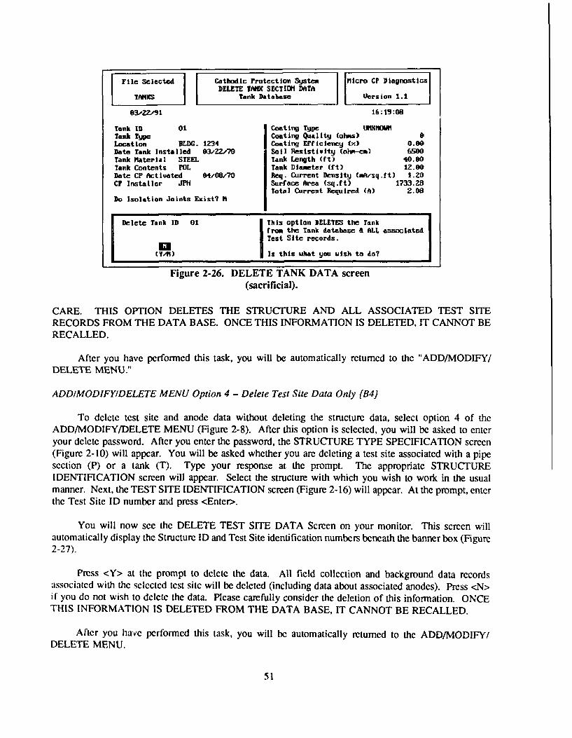
File Selected I Cathodic Protection System Micro CF DiagnosticsI DELETE TANK SECTIOM DATA
TAN Tank Data'base Vers ion 1.1
03/ZZ/91 16:19:08
Tank ID 01 Coating TypC uhIIOWITank Type ICoating Quality (olas) 0Location BLDG. 1234 Coating Efficiency W') 0.00Date Tank Installed 03/22/70 Soil Resistiulty (ohw-cm) 6500Tank Material STEEL Tank Length (ft) 40.00Tank Contents FOL Tank Diameter (ft) 12.60Date CP Activated 04/08/70 Req. Current Density (.fk/sq.ft) 1.20CP Installer JPH Surface Area (sq.ft) 1733.28
Total Current Required (A) 2.08Do Isolation Joints Exist? H
Delete Tank ID 01 This option DELETES the Tankfrom the Tank database A ALL associatedTest Site records.
Is this uhat you uish to &o7
Figure 2-26. DELETE TANK DATA screen(sacrificial).
CARE. THIS OPTION DELETES THE STRUCTURE AND ALL ASSOCIATED TEST SITERECORDS FROM THE DATA BASE. ONCE THIS INFORMATION IS DELETED, IT CANNOT BERECALLED.
After you have performed this task, you will be automatically returned to the "ADD/MODIFY/DELETE MENU."
ADD/MODIFY/DELETE MENU Option 4 - Delete Test Site Data Only [B4)
To delete test site and anode data without deleting the structure data, select option 4 of theADD/MODIFY/DELETE MENU (Figure 2-8). After this option is selected, you will be asked to enteryour delete password. After you enter the password, the STRUCTURE TYPE SPECIFICATION screen(Figure 2-10) will appear. You will be asked whether you are deleting a test site associated with a pipesection (P) or a tank (T). Type your response at the prompt. The appropriate STRUCTUREIDENTIFICATION screen will appear. Select the structure with which you wish to work in the usualmanner. Next, the TEST SITE IDENTIFICATION screen (Figure 2-16) will appear. At the prompt, enterthe Test Site ID number and press <Enter>.
You will now see the DELETE TEST SITE DATA Screen on your monitor. This screen willautomatically display the Structure ID and Test Site identification numbers beneath the banner box (Figure2-27).
Press <Y> at the prompt to delete the data. All field collection and background data recordsassociated with the selected test site will be deleted (including data about associated anodes). Press <N>if you do not wish to delete the data. Please carefully consider the deletion of this information. ONCETHIS INFORMATION IS DELETED FROM THE DATA BASE, IT CANNOT BE RECALLED.
After you have performed this task, you will be automatically returned to the ADD/MODIFY/DELETE MENU.
51

File Selected Cathodic Protection System Micr CF DiagnosticsADELETE TEST SITE DATA
FTRILEY Ft. Rilej Field Test Larsion 1.1
83/Z8/I 15:15:45
Pipe Identification ST24 QiTRTest Site ID IQICGAS
Location CORNER BULLARD & NORMANDYDescriptionUoendorSurface or Flush flounted? [S/FF]Tools RequIredNatural Potential (uolts) 0.000Intf. Bond Resistance (ohms) 0.00
Does Interference Exist?
Delete Test Site This option DELETES the Test SiteO1CHGAS froem the database a ALL
Field Collection records.a(Y/N) Is this uhat you uish to do?
Figure 2-27. DELETE TEST SITE DATA screen (sacrificial).
ADD/MODIFY/DELETE MENU Option 0 - Return to Main Menu {BS}
This option will return you to Sacrificial CP Diagnostic's main menu.
MAIN MENU Option 2 - Data Base-Related Reports (A4}
The Sacrificial CP Diagnostic System's MAIN MENU option 2 allows you to generate reportswhich retrieve and analyze specific data from the CP databases. After you select option 2 of the MAINMENU, the REPORT MENU (A5) will appear on your screen. To generate a report, select it from themenu and respond to the prompts. Many of the reports are displayed to the printer only, so make surethat your printer is on and loaded with paper. If you did not already configure CP Diagnostic for yourprinter by entering the printer control strings on the System Utility screen, be sure to do so beforeattempting to generate any reports. The reports that can be generated are explained below.
REPORT MENU Option I - Field Collection Forms [DI)
This report prints a series of field data collection forms (organized by pipe section) that can be usedby the field inspector. A data collection form lists all test sites associated with a pipe section, andcontains a description of each test site. The forms may be used to collect the anode current outputs andpipe-to-soil potentials (both with the anodes connected and disconnected) from the measurement pointsat each test site. Data may then be entered into Sacrificial CP Diagnostic from the data collection forms.To generate the report, select it from the menu. The inspection forms will begin printing as soon as theoption is selected from the menu. After the report has printed, you will be returned to the REPORTMENU.
REPORT MENU Option 2 - Trouble Readings Report [D2}
This report identifies all test sites with readings that do not meet the selected criterion for propercalihodic protection. To generate the report, select it from the menu and enter the earliest date that you
52

REPORT MENU Option 2 - Trouble Readings Report (D2}
This report identifies all test sites with readings that do not meet the selected criterion for proper
cathodic protection. To generate the report, select it from the menu and enter the earliest date that you
wish the readings to be analyzed at the prompt. Select the criterion that you wish to use from the CP
CRITERION MENU (Figure 2-28). The criterion should be selected with extreme care. See Chapter 1
for a detailed discussion and guidance on this subject. The report will begin printing as soon as you select
the critericri. The report prints every reading taken after the specified date that does not meet the selected
criterion.
REPORT MENU Option 3 - Structure Listing {D3)
This report provides a listing of all structures in the data base. It gives the structure ID and location.It is useful as a concise description of the overall structure inventory. To generate the report, select itfrom the menu. You will be presented with a screen that asks whether you wish to send the report to the[Slcreen, [Pirinter, or [Q]uit. Press the first letter of the option you wish to select. Printer [P] is thedefault option and may be selected by pressing <Enter>. If you choose to display the report on the screen,press the <Cntl> and <S> keys to stop or start the scrolling of the data that is being displayed. Press anykcy after the report has been displayed on the screen to return to the REPORT MENU. If you select[Q]uit, you will be returned to the REPORT MENU and the report will not be generated.
REPORT MENU Option 4 - Structure Master Listing {D4)
This report displays the background information for each structure recorded in the data base, provid-ing a more detailed description of the structures than the Structure Listing (Report 3). To generate thisreport, select it from the menu and respond to the [Sicreen, [Printer, or [Qluit prompt as described abovefor the Structure Listing report. If you choose to display the report on the screen, press the <Ctrl> and<S> keys to stop or start the scrolling of the data that is being displayed. Press any key after the report
File Selected Cathodic Protection System Mlicro Cl DilagnosticsTROUBILE READIfIGS REPORT
tICHAIR Ft. Hooed idLctar Vill Version 1.1
O6.O6a/91 10:~40:01
Please select the cathodic protectioncriterion that you wish to use.
| IpN| KIT.1 am In a I MiPfilI MI
2 300 HIllivolt Shift Criterion3 100 Nhlliolt Shirt Criterion4 -0.85 Volt Instant-Ott-Potential Criterion5 User-Specified On-Potenttal Range0 EXIT Withmat Printing Report
Figure 2-28. CP CRITERIA MENU screen(sacrificial).
53

has been displayed on the screen to return to the REPORT MENU. If you select [Q]uit, you will be
retumed to the REPORT MENU, and the report will not be generated.
REPORT MENU Option 5 - Field Collection Report [D5}
This report gives a complete listing of all field data (arranged by test point) collected at all test sitesduring a user-specified time period. The listing includes dates, potentials, and dielectric status for eachtest point. To generate the report, select it from the menu, and it will begin printing immediately. Afterthe report is printed, you will be returned to the REPORT MENU screen.
REPORT MENU Option 6 - System History Report fD6)
This report lists dates and descriptions of repairs that were performed and dates and locations thatfield measurements were taken for all structures throughout the life of the system. The listing is inchronological order. To generate the report, select it from the menu and it will begin printingimmediately. After the report is printed, you will automatically be returned to the REPORT MENUscreen.
REPORT MENU Option 7 - Test Sites Not Collected [D7}
This report prints the identifiers of all test sites from which field data has not been collected overa specified range of time. To generate the report, select it from the menu and enter the desired range ofdates at the prompt. To keep the default (current) date, simply press <Enter>. Respond to the [Sicreen,[Pirinter, or [Qluit option as discussed above. You will be returned to the REPORT MENU after thereport is printed.
REPORT MENU Option 8 - Repair History [D8}
This report prints the contents of the repair database including repair date, failure type, repair length,and cost of repair. The repairs are listed by year, and annual repair costs are totalled. This report can beprinted for structure or for all structures in the database. To generate the report, select it from the menu.At the prompt, enter a structure ID if you wish to print the report for one structure only, or enter "ALL"if you wish to print the report for all structures in the database. Press <Enter> after you type yourselection, and the report will be printed. You will be returned to the REPORT MENU after the report isprinted.
REPORT MENU Option 9 - Anode Current Output Drop (D9)
This report identifies the pipe section, test site, and anode current output for any test site that hasexperienced a drop in the anode current output over time during a user-specified time period. A signifi-cant drop in anode current output is defined to be a drop of at least 10 percent between any two readings(they need not be consecutive) or a drop of any amount over three consecutive readings (that is, two con-sccutive drops of any amount). To generate this report, select it from the menu and enter the earliest andlatest reading dates that you wish the report to consider. The report will print immediately after you enterthe dates, and you will be returned to the REPORT MENU after the report is printed.
REPORT MENU Option 0 - Return to Main Menu [D10)
This option returns you to the Main Menu screen of Sacrificial CP Diagnostic.
54

3 USER'S MANUAL FOR THE IMPRESSED CURRENT SYSTEM
Introduction
The Impressed Current CP Diagnostic program is a user-friendly record-keeping and diagnosticprogram for cathodic protection systems that use impressed current anodes. Background and field datais stored in several database files. The program provides information through a series of reports. Thepurpose of this chapter is to give detailed instructions on the operation of the program. All of the programoptions will be explained. The user will be guided through the steps of preparing data for input into theprogram, installing the program on the computer, configuring the program, creating databases, enteringbackground and field data, and generating reports. A sample implementation specification for theimpresscd current CP Diagnostic system is included in Appendix D.
Steps for Implementing and Using Impressed Current CP Diagnostic
Initial Implementation
In general, these steps will need to be performed just once, unless modifications are made to the CPsystem or to the protected structures that would change the background information.
1. Divide the CP system and protected structures into components as described below in "PreparingData for Input Into the Program."
2. Collect background data about the components as described in "Preparing Data for Input Intothe Program." This will probably require a field survey to verify the information. If a field survey isdone, the first set of field data (structure-to-soil potentials, anode current outputs, dielectric conditions, andrectifier readings) should be collected at this time.
3. Install and configure the program as described under MAIN MENU OPTION 4 - System Utility.
4. Create databases in which to input the CP system data as described under MAIN MENUOPTION 3 - Database Administration.
5. Input background data into the databases as described under MAIN MENU OPTION 1 - DataEntry and Modifications, Submenu Option [1] - Add/Edit Rectifier/Structure/Test Site Background Data.
6. If the first set of field data was collected, enter it into the field collection database as describedunder MAIN MENU OPTION I - Data Entry and Modifications, Submenu Option [2] - Add/Edit TestSite Field Collection Data. If you wish to store field collection data that was collected in the past, youmay enter it also.
7. Generate the reports of interest as described under MAIN MENU OPTION 2 - Database RelatedReports.
55

Periodic Collection of Field Data
1. Generate field collection forms as described under MAIN MENU OPTION 2 - Database RelatedReports, Submenu Option [11 - Field Collection Forms.
2. Collect field data.
3. Input field data into program as described under MAIN MENU OPTION I - Data Entry andModifications, Submenu Option [21 - Add/Edit Test Site Field Collection Data.
4. Generate the reports of interest as described under MAIN MENU OPTION 2 - Database RelatedReports.
Preparing Data for Input Into the Program
Overview
Before the program can be used, data concerning the CP system and the structure that it protectsmust be compiled. All of the following sections of this manual assume that this data has been compiledand is ready to input into the program. Each system component will be given its own unique identifica-tion number. Appendix E contains a chart which shows the relationships between system components.It will be helpful to refer to it while you are reading this section. A record in the database will be createdfor each component and data about it will be collected and entered into the record. All of the records willbe stored in the program database files. It is recommended that you obtain maps and/ or drawings thatshow as much detail as possible about the system and the protected structures.
CP Diagnostic defines the impressed current CP system itself as a collection of rectifiers, junctionboxes, and "test sites." Each rectifier has one or more junction boxes associated with it. Each junctionbox has a collection of anodes associated with it. Each rectifier protects one or more structures. Inaddition, each structure has a collection of "test sites" associated with it.
Rectifiers
Begin collecting data for Impressed Current CP Diagnostic by assigning a Rectifier ID (up to 10characters) to each rectifier in the CP system. Mark the rectifiers and their ID's on the system map. Thebackground data required for each rectifier is shown in Figure 3-12. You may wish to use the RectifierBackground Data Sheet in Appendix F to help organize and compile the data. Fill out one form for eachrecti fier.
Junction Boxes and Anode Ground Beds (Underground Structures)
If any of the rectifiers identified in the preceding paragraph protect underground structures, junctionbox and anode ground bed data must be collected for each. As stated above, each rectifier that protectsunderground tanks or pipes has one or more junction boxes associated with it. Typically, the junction boxcontains a series of terminals to which anodes are connected and at which anode currents may bemeasured. Assign a junction box ID (up to five characters) to each junction box. These ID's should bemarked on the system map. Background data as shown in Figure 3-14 is required for the anodes whichare connected to the junction box. Anode currents should be measured at each termianl when the program
56

is implemented. In addition, initial anode current outputs (i.e., those that were mesured when the CP
system was installed) should be collected and recorded if they are available. You may wish to use the
Ground Bed Data Sheet in Appendix F to help organize and compile this data. Fill out one form for each
junction box/ anode ground bed.
Elevated Water Storage Tank Anodes
If any of the rectifiers identified above protect elevated water storage tanks, information concerningthe anodes inside the tank must be compiled for each. The data that is required for each rectifier/ waterstorage tank is shown in Figure 3-16. You may wish to use the Water Tank Anode Background DataSheet in Appendix F to compile the data. Fill out one form for each rectifier/ water storage tank.
Defining the Protected Structures
The next step in preparing to implement Impressed Current CP Diagnostic is to define and collectdata concerning the structures that are protected by each rectifier that was identified previously. ImpressedCurrent CP Diagnostic recognizes three types of protected structures: underground pipes (such as gasdistribution pipes), underground storage tanks, and elevated water storage tanks. A piping network isdefined as a collection of "pipe sections." Each pipe section will have its own individual record in thedatabase in which the information associated with it will be stored. For a system of tanks, each tank willhave its own individual record in the database that contains the data associated with it.
To define a piping network, it is essential to have a map of it. Pipe sections are identified by thePipe ID and the Section ID. The system is divided up into pipes, and each pipe is assigned a Pipe ID.Each pipe is then divided up into sections, and each section is assigned a Section ID. Therefore, a sectionis a subdivision of a pipe and an individual pipe may consist of many sections. A "pipe section" is thelength of pipe referred to by the combination of the Pipe ID and the Section ID. A pipe section shouldhave a consistent diameter, material of construction, coating type and quality, date of installation, andrequired current density along its entire length. Soil resistivity should also remain fairly consistent alongthe length of the section, although this is not critical to the program output. With these criteria in mind,divide the piping network up into pipes and pipe sections. Develop an identification system that fits theneeds of your installation. The Pipe ID may be up to 10 characters (letters and/or numbers) in length.The Section ID may be up to four characters in length. For example, a gas main that serves severalbarracks might be given a Pipe ID of "BARRACKS" and Section ID's of 1, 2, 3, etc. A gas main thatserves the 3600 Block might be given a Pipe ID of "3600BLOCK" and Section ID's of 1, 2, 3, etc. Thelocation of each pipe section should be marked on the map. The data required for each pipe section isshown in Figure 3-20. In addition to this data, mark and note the location of isolation joints. Isolationjoints associated with a pipe section are numbered consecutively starting with 1. You may wish to usethe Pipe Section Background Data Sheet in Appendix F to help organize and compile the data. Completeone form for each pipe section. This data is then ready to input into CP Diagnostic.
To define a system of tanks, assign a Tank ID (up to 10 characters) to each tank. Figure 3-21shows the data that is required for each underground storage tank. Figure 3-22 shows the data that isrequired for each elevated water storage tank. You may wish to use the Underground Tank BackgroundData Sheet or the Water Storage Tank Background Data Sheet from Appendix F to organize and compilethe data. Complete one form for each tank. In addition, if the piping associated with the tank iscathodically protected, an underground piping record (as described in the preceding paragraph) may becreated for it. This data is then ready to input into the program.
57
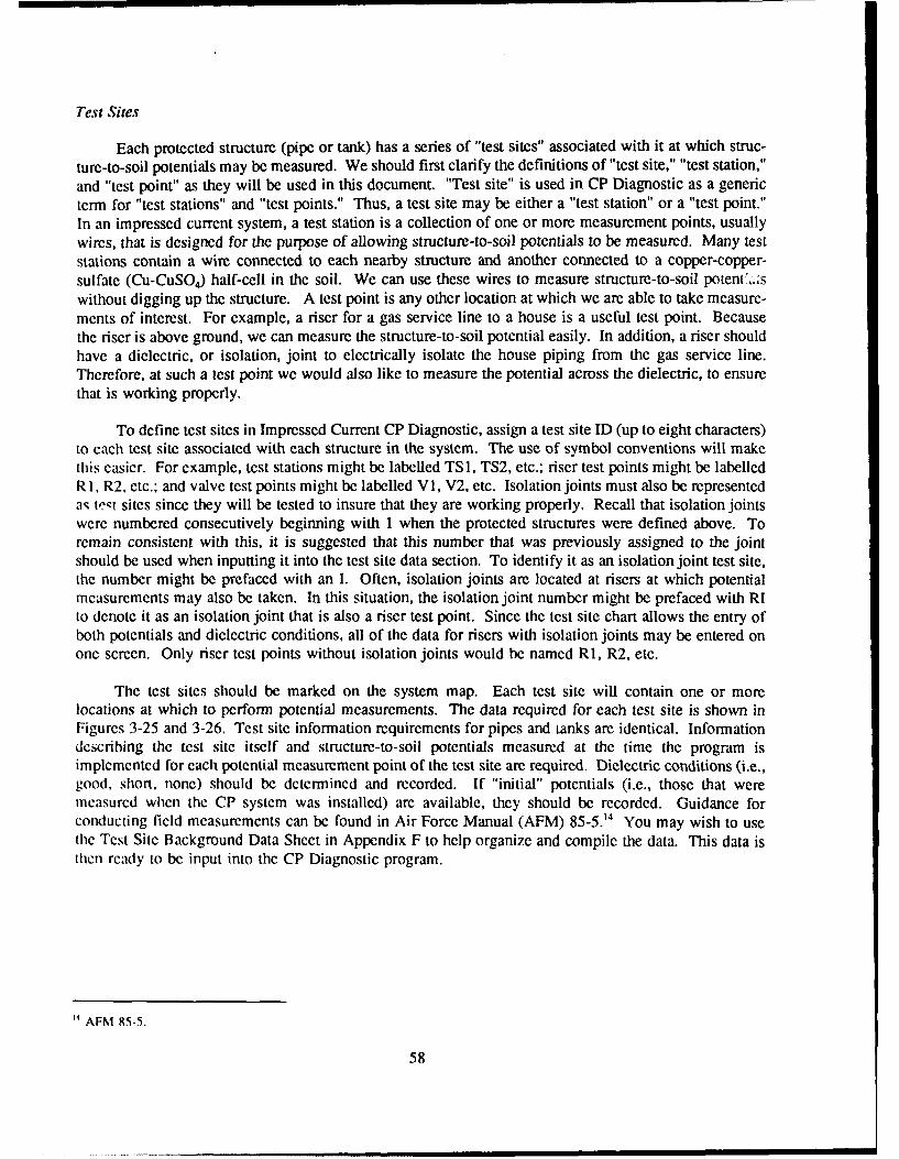
Test Sites
Each protected structure (pipe or tank) has a series of "test sites" associated with it at which struc-ture-to-soil potentials may be measured. We should first clarify the definitions of "test site," "test station,"and "test point" as they will be used in this document. "Test site" is used in CP Diagnostic as a genericterm for "test stations" and "test points." Thus, a test site may be either a "test station" or a "test point."In an impressed current system, a test station is a collection of one or more measurement points, usuallywires, that is designed for the purpose of allowing structure-to-soil potentials to be measured. Many teststations contain a wire connected to each nearby structure and another connected to a copper-copper-sulfate (Cu-CuSO 4) half-cell in the soil. We can use these wires to measure structure-to-soil poten',.,f'swithout digging up the structure. A test point is any other location at which we are able to take measure-ments of interest. For example, a riser for a gas service line to a house is a useful test point. Becausethe riser is above ground, we can measure the structure-to-soil potential easily. In addition, a riser shouldhave a dielectric, or isolation, joint to electrically isolate the house piping from the gas service line.Therefore, at such a test point we would also like to measure the potential across the dielectric, to ensurethat is working properly.
To define test sites in Impressed Current CP Diagnostic, assign a test site ID (up to eight characters)to each test site associated with each structure in the system. The use of symbol conventions will makethis easier. For example, test stations might be labelled TS1, TS2, etc.; riser test points might be labelledRI, R2, etc.; and valve test points might be labelled VI, V2, etc. Isolation joints must also be representedaq tvt' sites since they will be tested to insure that they are working properly. Recall that isolation jointswere numbered consecutively beginning with 1 when the protected structures were defined above. Toremain consistent with this, it is suggested that this number that was previously assigned to the jointshould be used when inputting it into the test site data section. To identify it as an isolation joint test site,the number might be prefaced with an I. Often, isolation joints are located at risers at which potentialmeasurements may also be taken. In this situation, the isolation joint number might be prefaced with RIto denote it as an isolation joint that is also a riser test point. Since the test site chart allows the entry ofboth potentials and dielectric conditions, all of the data for risers with isolation joints may be entered onone screen. Only riser test points without isolation joints would be named R1, R2, etc.
The test sites should be marked on the system map. Each test site will contain one or morelocations at which to perform potential measurements. The data required for each test site is shown inFigures 3-25 and 3-26. Test site information requirements for pipes and tanks are identical. Informationdescribing the test site itself and structure-to-soil potentials measured at the time the program isimplemented for each potential measurement point of the test site are required. Dielectric conditions (i.e.,good, short, none) should be determined and recorded. If "initial" potentials (i.e., those that weremeasured when the CP system was installed) are available, they should be recorded. Guidance forconducting field measurements can be found in Air Force Manual (AFM) 85-5.14 You may wish to usethe Test Site Background Data Sheet in Appendix F to help organize and compile the data. This data isthen ready to be input into the CP Diagnostic program.
' AFM 85-5.
58

Installing Impressed Current CP Diagnostic
The Impressed Current Cathodic Protection Diagnostic System is distributed on a single disk whichcontains the following files:
SCHEMAA.DBF SCHEMAI.DBF SCHEMAN.DBFSCHEMAB.DBF SCHEMAJ.DBF SCHEMAR.DBFSCHEMAC.DBF SCHEMAM.DBF SCHEMAT.DBFSCHEMAD.DBF DB.DBF SCHEMAU.DBFSCHEMAF.DBF GSI.DBF SCHEMAW.DBFSCHEMAG.DBF ICP.EXE SCHEMAX.DBFSCHEMAH.DBF INSTICP.BAT SCHEMAY.DBF
Before doing anything with the distribution disk you should make a backup copy of the disk usingthe DOS "DISKCOPY" command. If you are not familiar with the DOS operating system or the"DISKCOPY" command, please consult your DOS manual.
As stated in Chapter 1, CP Diagnostic operates on an IBM-compatible microcomputer system with640K of Random Access Memory (RAM). A hard drive is required because of the large amounts of datastored by the program. It supports both color and monochrome monitors. The program can be configuredto support most dot matrix and laser printers.
First, check your CONFIG.SYS file to see if it contains the statement:
FILES = 50
If this statement is not in the CONFIG.SYS file, you must add it. If there is a FILES statement, but thenumber is less than 50, you must change it to 50. Consult your DOS manual for assistance. If theFILES=50 statement is not in your CONFIG.SYS file, CP Diagnostic will not run properly.
IMPORTANT: In the installation procedure that follows:
A: refers to the letter designation of the flomtv disk drive from which you are installing the program.
C: refers to the letter designation of the hard drive on which you are installing the program.
Your disk drives may or may not be designated by the letters A: and C:. If not, substitute the appropriateletters for A: and C:.
To install the Impressed Current Cathodic Protection Diagnostic System on a hard disk, place thebackup disk into the floppy disk drive of your computer. You will see the DOS prompt "C:>" to whichyou will enter the following command "A:". The DOS prompt will now read "A:>" to which you willrespond "INSTICP A: C:". Your screen should show:
C:> A:A:> INSTICP A: C:
(Note: the C:> and A:> portions of the commands are the DOS prompts and are not user-enteredcommands.) The INSTICP program creates a directory named ICP on the hard disk and copies all the
59

files needed to run the Impressed Current Cathodic Protection Diagnostic System to the ICP directory.After the INSTICP program has finished, the system is ready to use. Remember to store the distributionand backup disks in a safe place.
Starting the Impressed Current CP Diagnostic System
Before starting the Impressed Current Cathodic Protection Diagnostic System (ICP), access thedirectory and drive containing ICP and its support files. If you have just installed the program you arealready in the correct directory. If not, you must change to the ICP directory. For example, if theImpressed Current Cathodic Protection Diagnostic System were installed on disk drive C the followii,,commands would access the drive and directory containing ICP:
A:> C:C:> CD ICP
(Note: The A:> and the C:> are DOS prompts and are not user-entered.) The program is thenstarted by entering the command ICP at the DOS prompt. As the program starts, it displays an openingscreen which lists the program authors. Press any key to continue. After the opening screen is cleared,the program displays either the MAIN MENU screen or a "MISSING FILE(S)" error screen. If the errorscreen appears, note the missing file(s), copy them from the backup disk and restart the program.
Diagram of Program Flow
To assist you with navigating throughout the Impressed Current CP Diagnostic Program, a diagramshowing the program flow is included in Appendix G. This diagram consists of five sheets labelled Athrough E. All menus and menu options in the diagrams are cross-referenced with their descriptions inthe main text of this manual. Cross references are given in brackets { ) and consist of a letter and anumber. The letter refcrs to the sheet of the diagram on which the option or menu appears. For example,in the text below, the cross-reference [Al I appears after the title "Main Menu Overview." To locate thisin the diagram, turn to Appendix G and find sheet A. Block (A]) is located at the top of sheet A. Byusing the diagrams and the cross-references, you can easily determine your location in the program at anytime.
General Rules for Operating the Menus
Impressed Current CP Diagnostic is a menu-driven, user-friendly program. There are two basic rulesthat apply to the operation of ALL menus throughout the program.
1. Menu options are sclected by (1) typing the number of the option or (2) moving the selectionbar to the desired option and pressing <Enter>. Once an option is selected, the program eitherexecutes the option or displays a message about its failure to perform the option.
2. The <Esc> key can be used to move back to the previous menu or program screen.
60

About Passwords
Certain sections of the CP Diagnostic program are password-protected to reduce the chance of
unauthorized persons editing or deleting your data. There are three passwords which you may set: the
add/edit password, the delete password, and the general system information password. The add/edit
password is used to control access to the "Add/ Edit Rectifier/ Structure/ Test Site Data" option and the"Add/ Edit Test Site Field Collection Data" options of the ADD/ MODIFY/ DELETE menu. The delete
password is used to control access to all options that allow deletion of rectifiers, structures, test sites, orentire databases. The general system information password is used to control access to the "SystemUtility" option of the MAIN MENU. Procedures for setting these passwords will be discussed in the"System Utility" section.
A particular password only needs to be entered once during a program run. For example, once youenter your delete password, you will be allowed access to all "delete" options until you exit the program.You will not be prompted for the password every time you attempt to access a "delete" option, even ifyou have performed other program operations in the meantime. After you exit the program and thenrestart it, you will be prompted for the passwords again.
Most of the instructions for each program option described in this manual are written with theassumption that the password necessary to access the option has not yet been entered. If you have, in fact,entered the password during your current working session, disregard the references to the passwordscreens.
MAIN MENU Overview {A1}
The MAIN MENU screen (Figure 3-1) illustrates a number of features of the ICP user interface.The menu displays an informative header across the top of the screen. The header contains three informa-tion boxes: the File Box, the Banner Box, and the Version Box. The File Box (top left of the screen)displays the name of the active Cathodic Protection data base. The Banner Box (top middle of thescreen) displays the name of the program, the current location in the program, and a short description ofthe active CP data base. The program Version Box (top right of the screen) displays ICP's versionnumber. The current date and time are displayed below the file and version boxes to complete theprogram's header. On a color monitor the color of the header provides the following additional informa-tion:
" RED All Error Screens" WHITE The MAIN MENU and Secondary Menu Screens" CYAN All Other Menu or Option Screens
ICP is operated via the MAIN MENU shown in Figure 3-1. The MAIN MENU has five options.The following sections of this manual describe each of the program's main and secondary menu optionsin detail.
MAIN MENU Option 1 (Data Entry & Modification) and Option 2 (Data Base-Related Reports) areordered before Options 3 and 4 in the MAIN MENU because they are used most often. Most of yourwork in the Impressed Current Cathodic Protection Diagnostic System will be done through Options I and2. However, there are several procedures which you must perform initially when using CP Diagnostic forthe first time. You must configure the program for your hardware using MAIN MENU Option 4. You
61

fieSelected Cathodic Protect ion Syjste Micro CP Diagnostics
Ft. Hooa cHair Uit Versio,, 1.1
iIZ,41 15:48:43
2 Data'ase Related Reports.3 beta1ase Administration.4 System Utility.0 Exit CP Diagnostics.
I cniMew Ass istance
Press the numbcr of your selection or use the ti keys anti [Enter].[Esc) Exit Menu
Figure 3-1. MAIN MENU (impressed current).
must then create and/or select a database for use using MAIN MENU Option 3. Thus, MAIN MENUOption 4 will be discussed first, followed by Option 3. Options 1 and 2 will be discussed last.
MAIN MENU Option 4- System Utility [AS)
This option is used to configure CP Diagnostic for your hardware and to set passwords. Ifpasswords have not yet been set, the General System Information screen (Figure 3-2) {A9) will appearimmediately after this option is selected. If passwords have been set, you will be prompted to enter yourgeneral system information password. Type your password and press <Enter>. Your password will notbe displayed on the screen as you type it. The General System Information screen will appear after youhave entercd your password correctly.
Enter your name (or the installation's name) and address in the top portion of the screen.
Each of the three kinds of data manipulation-add/edit data, delete data, and edit general systeminformation (system utility)-has its own password. Passwords may be up to six characters in length.Enter the desired passwords in the appropriate location. Note that once you enter a password for the GSI(system utility) module, you will not be able to access this screen again without it. Thus, it is critical thatyou commit the passwords to memory or write them down in a safe place.
The printer codes are needed to configure CP Diagnostic for your printer so that the reports printcorrectly. The printer codes are entered in decimal ASCII. Consult your printer manual to determine thecodes needed to switch your printer to compressed mode and enter them as the 17-characters-per-inchcodes. Next, determine the codes needed to cancel compressed mode and enter these as the 10-character-per-inch codes.
62

File Selected I Cathodic P'rotection System Micro CIF DiagnosticsI GENEAL SYtSTEM IH 701MT lOl
PICMAI I I Ft. Hooa Mc~air 1)111 Version 1.1
04/." 1 13:42:13
Name .S ryCrso nierAddress ' 0 0City hmaiIlL i q_0s
Password to access ADDeEDIT ModulePassword to access DELETE ModulePassword to access GSI Module
Printer codes: 10 cpl Z"? 38 1 4: l1sPrinter codes: 17 cpi
(in decimal f ,SCll)
Use Color Monitor settings
Figure 3-2. GENERAL SYSTEM INFORMATION screen (impressed).
The monitor setting controls whether or not CP Diagnostic screens appear in color. If you have acolor monitor, enter "Y" after the "Use Color Monitor Settings?" prompt. If you do not have a colormonitor, enter "N".
CP Diagnostic is now configured for your hardware. These settings will be stored by the program.You will only need to repeat this setup procedure if you wish to change the passwords or if you use theprogram with a different printer or a different monitor type. To return to the MAIN MENU, hit <Esc>or press <Enter> on the "Use Color Monitor Settings" field.
MAIN MENU Option 3 - Data Base Administration {A6)
The Data Base Administration option of the MAIN MENU is used to manipulate the database filesthat are stored by CP Diagnostic. Databases can be added (created), selected for use, deleted, andrcindexed using this option. When you select the MAIN MENU's option 3, the "DATA BASE ADMIN-ISTRATION MENU" screen will appear (Figure 3-3) (A7).
DATA BASE ADMINISTRATION MENU Option I - Add/Select a Data Base {El)
This option allows you to (1) add (create) a new database, (2) select an existing database for use.or (3) register an existing database file with the program. This option also alerts you if files are missingfrom a database that you are attempting to select. Note that if you are using CP Diagnostic for the firsttime, you will need to add a database before entering any data.
The Impressed Current Cathodic Protection Diagnostic System can maintain many separate CP databases. The amount of information stored is limited only by the available space on the hard disk. Youmay wish to store all of your data in one database, or you may wish to divide it up into several databases.Storing data in more than one database is advantageous when you have a large amount of data or whenyou are maintaining data for more than one installation. Each CP data base is given a one- to seven-character name within the Impressed Current Cathodic Protection Diagnostic Program. The program
63

Sfile Selctd Cathodic Protection SUsten Micro CF Diagnostics
DATA BSE ADMINISTRATION MINUPATTON Ft. I4oo-Pat-ton Park Version 1.1
10G,'9/51 11:07:29
2 letea a Database.3 Relndex Selected Database.4 Register an Existing Database.0 Return to Main Menu.
Menu Assistance
Press the number of your selection or use the t4 keys and Eier].[Esc] Exit Menu
Figure 3-3. DATABASE ADMINISTRATION MENU screen(impressed current).
creates a series of 14 disk files to store the information for each of the databases that is created. Thenames of the disk files consist of the one- to seven-character database name plus a single character. Forexample, the disk files for the CP data base HOOD would have the following names:
HOODA.DBF Junction box field collection comments for the CP data base HOODHOODB.DBF Junction box background file for the CP data base HOODHOODC.DBF Rectifier information file for the CP data base HOODHOODD.DBF Field collection information file for the CP data base HOODHOODFDBF Rectifier field collection information for the CP data base HOODHOODG.DBF Anode background information for the CP data base HOODHOODH.DBF Water tank information file for the CP data base HOODHOODI.DBF Isolation joint information file for the CP data base HOODHOODJ.DBF Water tank anode background information file for the CP data
base HOODHOODM.DBF Pipe section information file for the CP data base HOODHOODN.DBF Junction box and anode field collection file for the CP data base HOODHOODR.DBF Repair information file for the CP data base HOODHOODT.DBF Test site information file for the CP data base HOODHOODU.DBF Underground storage tank information for the CP data base HOODHOODX.DBF A cross-reference file linking pipe sections to a rectifier for CP data base HOODHOODY.DBF Test site field collection comments for the CP data base HOOD
When you choose the Add/Select a Data Base option from the Data Base Administration Menu, theSELECTING A DATA BASE screen will appear (Figure 3-4). This screen lists all the Cathodic Protec-tion data bases (if any) that have been entered into the Impressed Current Cathodic Protection DiagnosticSystem.
To ADD (Create) a New Database: {E2) As stated above, you will need to do this if you are usingthe program for the first time. To create a CP data base, simply type a one- to seven-character name for
64

File elected Cathodic Protectiou Soist Icro CP DiagnosticsS.ETING A DATASE
NIR I I Ft. Hood McKair Uill Version 1.1
04/12/o91 IS :49 :SS
Databs:
PATTOIN Ft. Hood-Patton Park"MIIR Ft. Hood McNair Uill
(PgUp) 4FgDu> previoUB - UeXt page (ESC> quit
Figure 3-4. SELECTING A DATABASE screen (impressed).
it at the "Database" prompt of the SELECTING A DATA BASE screen and press <Enter>.IMPORTANT! The database name must not include any spaces. For example, TEST DB would not bean acceptable database name. In addition, the database name must begin with a letter. The name mustbe different from the other existing database names. When a database name is entered that does notalready exist in the program, the CREATING A DATA BASE screen appears. This screen asks you ifyou want to create a new CP data base. If you answer no <N>, you are returned to the DATABASEADMINSTRATION MENU, and the currently selected data base is not changed. If you answer yes <Y>,a new CP data base (with the name that you have specified) is added to the system. Before the new database is created, it must be given a description. The program prompts for a short (up to 20-character)description of the data base. The data base files are then created, the data base is automatically selected,and you are returned to the DATABASE ADMININSTRATION MENU.
To SELECT an Existing Database for Use: {E3) All CP data bases that have been previouslyentered into the system are listed in the "selecting a database" screen. If there are many CP data baseson the disk, the list may contain multiple pages. The <PgUp> and <PgDn> keys may be used to pagethrough multiple-page listings of Cathodic Protection data base files. To select one of the listed databasesfor use, type its name at the "Database" prompt and press <Enter>. To exit the SELECTING A DATABASE screen without changing the currently active CP data base, press <Esc>. After the data base isselected, its name and description are placed in the program's header, and you are returned to theDATABASE ADMINSTRATION MENU.
Note that if this is not the first time you have used the program, the data base that was in use thelast time the program was run remains active when the program is started again and does not need to beactivated with the Data Base Administration option.
If Some Files Are Missing from the Selected Database: Occasionally all or some of the disk filesof a Cathodic Protection data base may be missing. This can occur, for example, if you delete the filesusing DOS and forget to remove the CP data base name from ICP. The MISSING FILE(S) Screen alsoappears when the program is started using an incomplete or missing data base. When this occurs, theMISSING FILE(S) Screen (Figure 3-5) appears. To use the incomplete data base, note the names of the
65
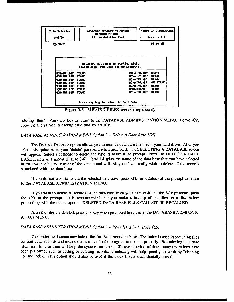
File Selected Cathodic ?rotcctloai Syjstem Micro CF Blagnostics
MISSING TILE(S)PATTON Ft. Hood-Patton Park Uersion 1.1
6Z."Z8/91 16:26:15
Database not found on working disk.Please copy from your backup diskette.
18C1AJI.DBF FOUND 11CHAII.DB1F FOUNPIMCAIRI .DBF FOUND HCHAIRY.DBF FOUND
MCNAIRT.DIF FOUND MCMAIRG.DBF FOIDt CIRD.DBF FOUND MCHAIRM.DBF NOT FOUNDMCNIRIII.DBF FOUND MCHAIRA.DBF FOUNDMCNAIIC.DBF FOUND NC IIIX.DHf FOUNDlCNAIRF.DBF FOUND MCIIAIRB.DBD FOUND
Press ang key to return to Main 1eau
Figure 3-5. MISSING FILES screen (impressed).
missing file(s). Press any key to return to the DATABASE ADMINISTRATION MENU. Leave ICP,
copy the file(s) from a backup disk, and restart ICP.
DATA BASE ADMINISTRATION MENU Option 2 - Delete a Data Base [E4)
The Delete a Database option allows you to remove data base files from your hard drive. After yo'select this option, enter your "delete" password when prompted. The SELECTING A DATABASE sc-eenwill appear. Select a database to delete and type its name at the prompt. Next, the DELETE A DATABASE screen will appear (Figure 3-6). It will display the name of the data base that you have selectedin the lower left hand corner of the screen and will ask you if you really wish to delete all the recordsassociated with this data base.
If you do not wish to delete the selected data base, press <N> or <Enter> at the prompt to returnto the DATABASE ADMINISTRATION MENU.
If you wish to delete all records of the data base from your hard disk and the SCP program, pressthe <Y> at the prompt. It is recommended that you make a backup of the files on a disk beforeproceeding with the delete option. DELETED DATA BASE FILES CANNOT BE RECALLED.
After the files are deleted, press any key when prompted to return to the DATABASE ADMINSTR-ATION MENU.
DATA BASE ADMINISTRATION MENU Option 3 - Re-Index a Data Base (E5)
This option will create new index files for the current data base. The index is used in seai, hing filesfor particular records and must exist in order for the program to operate properly. Re-indexing data basefiles from time to time will help the system run faster. If, over a period of time, many operations havebeen performed such as adding or deleting records, re-indexing will help speed your work by "cleaningup" the index. This option should also be used if the index files are accidentally erased.
66

rieSlce Cathodic Protect ion Syjstem Mlicro Ci' Diagnostics[ ~ j I DELETE A DATABASEPATTON Ft. Hoo-Patt a Park I Version 1.1
7Za08,3 1:18:26
Delete Database PATTO This option DELETES All Recardsfrom the Selected database.
(IAH) Is this what gon wish to do7
Figure 3-6. DELETE A DATABASE screen (impressed).
You will be asked if you want to rebuild the index for the currently selected data base (Figure 3-7).If this is what you want to do, press <Y> for YES. After indexing is complete, press any key to returnto the DATABASE ADMINISTRATION MENU. If this is not what you want to do, press <N> for NO.The program will return to the DATA BASE ADMINISTRATION" menu.
DATABASE ADMINISTRATION MENU Option 4 - Register an Existing Database [E6)
It is possible that existing CP data bases will not be listed in the SELECTING A DATA BASEScreen's data base list. For example, this occurs if you install a new version of ICP on a computer withexisting CP data bases. Before these data bases can be selected for us , they must be "registered" withthe program so that it recognizes their existence. To "register" an existing data base with the system, typeits name at the "Database" prompt of the SELECTING A DATA BASE Screen. The MISSING FILE(S)Screen (Figure 3-5) will list any files of the data base that may be missing. If any of the data base filesare missing, note their names, exit the program, and copy them from a backup disk, then restart the ICPprogram, and select the data base. If no files are missing, the MISSING FILE(S) Screen is supplementedwith the message that the data base is being added to the system. You are then prompted to enter a newdescription for the data base. After you enter the description, the new database becomes the currentdatabase in use, and you are returned to the MAIN MENU.
DATA BASE ADMINISTRATION MENU Option 0 - Return to Main Menu [E7)
This option returns you to the Main Menu of Impressed Current CP Diagnostic.
MAIN MENU Option 1 -- Data Entry & Modification {A2)
The Data Entry and Modification option of the MAIN MENU is used to create and updateinformation about cathodic protection systems in the currently active CP data base. A CP data base mustbc active (selected) before this option can be used. If no CP data base is active when you select the DataEntry and Modification Option, the SELECTING A DATABASE screen will appear. Type the name of
67

F ]elce Cathodic Protection System Mlicro CF DiagnosticsRE BUILD INDEX FILES
PATTON Ft. Hood-Patten Park V ersion 1.1
Z.-Z8.,91 10:18:55
This will rebuild the index for the currently selected database.Do you wish to continue?
N
Figure 3-7. REBUILD INDEX FILES screen (impressed).
the database that you wish to work with at the prompt. If you attempt to exit the SELECTING ADATABASE screen before typing a database name, the program displays the error message:
"You can not perform option 1 without first selecting a data base!Press any key to continue."
You will not be allowed to exit this screen without selecting a database.
After you have selected the Data Entry & Modification option and have an active database, theDD/MODIFY/DELETE MENU {A3) will appear. You will notice that the ADD/ MODIFY/ DELETEMENU Screen displays four options (Figure 3-8). Select the operation you wish to perform in the usualmanner.
General Rules for Data Entry and Modification
CP system data is entered via a series of screens, each of which contains a series of promptsfollowed by blank spaces, or "fields," in which the data is to be entered. There are several general rulesthat apply throughout all of the Data Entry and Modification screens.
1. Enter data in each field by typing your response and pressing the <Enter> key. The cursor thenmoves to the next field.
2. If the information for a field is not available, press <Enter> to bypass that" field and move theprompt to the next field. The former field will be left blank. If the information for that field becomesavailable at a later date, it may be entered into the program at that time.
3. The backspace and delete keys may be used to correct mistakes in data entry. The backspacekey will erase the character immediately to the left of the cursor. The delete key will erase the characterat the cursor.
68

File Selected I Cathodic Protection System Micro C? DiagnosticsI AT)D,MODIY/DEMEE KEM
PATTON Ft. Hoot-Patton Park Uera ion 1.1
10/30/91 69:66:18
2 ADD/DIT Field Collection Data3 DELETE Rectiier/Structure/Test Site Data0 Exit to Main Menu.
lenu Assistance
Press the number or y~ selection or use the tt keys and [Enter].lEst) Exit Menu
Figure 3-8. ADD/MODIFY/DELETE MENU (impressed).
4. The insert key may be used to toggle between insert mode and typeover mode.
5. The left and right arrow keys may be used to move the cursor within the field that you arecurrently editing.
6. The up arrow key may be used to move to the field above the one you are currently in and thedown arrow key may be used to move to the field below it.
ADD/MODIFY/DELETE MENU Option I - ADD/MODIFY Rectifier/Structure/Test Site Background [B)
This option allows you to create new rectifiers, junction boxes, structures, test sites, and anode beds,and enter the associated data into the system. It also allows you to edit data for existing rectifiers,junction boxes, structures, test sites, and anode beds.
After you choose this option, the ENTER ADD/EDIT PASSWORD screen (Figure 3-9) will appear.At the prompt, type your add/edit password and press <Enter>. The password will not be displayed onthe screen as you type it.
After you enter your password, the SELECTING A RECTIFIER screen appears (Figure 3-10). Theidentification numbers of existing rectifier records are displayed on this screen. If you wish to edit anexisting rectifier record (or the structure, junction box, or test site data associated with an existing rectifierrecord), consult this list. The <PgUp> and <PgDn> keys are used to scroll through the pages of the list.To select an existing rectifier record for editing, type the Rectifier ID (up to 10 characters) at the promptand prss <Enter>.
If you wish to create a new rectifier record, type a new Rectifier ID at the prompt. If you enter aRectifier ID that does not already exist in the program (i.e., does not appear on the list), the screen ofFigure 3-1 1 appears. This screen asks whether the rectifier protects underground structures (pipes orunderground storage tanks) or water tanks.
69
Siie Sclccted Cathodic Protection System Mlcro CT DiagnosticsZHDTER ADD/EDIT PASSWORD
MlMl Ft. Noma Mclair Vill Version 1.1
OZ.Z8/91 13:08:54
Enter Password
Figure 3-9. ENTER ADD/ EDIT PASSWORD screen (impressed).
File Selected Cathodic Frotection SUstem Miicro CF DiagnosticsSELECIIHG A RECTIFIER
ICIMAIR Ft. Hood lcfair Vill I Version 1.1
OIZ91 15:50:49
Pectirier ID:
297
(PIp) (?gln> preuious * next page (ESC) quit
Figure 3-10. SELECTING A RECTIFIER screen (impressed).
70

Fii Selectecd Cathodic Protection Ssten Micro CF DiagnosticsI0TECTED STRUCTURE TYPE
Iq(ftIR Ft. Hood Mclair Uill Version 1.1
4,1591 11:42 :17
Does this rectifier protect water tanm (W)or underground structures (U)?
Please enter U or U: 3
Figure 3-11. SPECIFY PIPE OR TANK screen (impressed).
After you have entered the Rectifier ID at the prompt, the ADD/EDIT RECTIFIER DATA screen (Figure3-12) will appear. At the bottom of this screen appears a submenu, the ADD/EDIT BACKGROUNDINFORMATION Submenu. (CI)
ADD/EDIT BACKGROUND INFORMATION SUBMENU Option 1 - Add/Edit Rectifier Back-ground. (C2) This option allows you to add or edit background information about the rectifier that youhave selected. After you select this option, the submenu will disappear from Rectifier Screen #1 shownin Figure 3-12. As usual, type the appropriate information at the corresponding prompts and press<Enter> to move to the next field. Rectifier Screen #2 (Figure 3-12a) allows you to enter backgroundinformation for up to three rectifier circuits. To move to Rectifier Screen #2, press <Enter> on the lastfield of screen #1 or press <Esc> at any point on screen #1.
When numeric values are entered on the ADD/EDIT RECTIFIER DATA screen, the program willvalidate the value entered for each numeric field. A message will appear at the bottom left comer of thescreen if a field value is invalid. Type a valid entry to correct it. The percentage value of rectifierefficiency is automatically calculated by ICP according to Equation 4 (Chapter 1).
When you have finished entering information for a particular rectifier in the ADD/EDIT RECTIFIERDATA screens (i.e., afte- you have pressed <Enter> on the last field of the screen), a series of screensrelated to the rectifier will appear on your monitor.
If the rectifier protects underground structures, these screens are the JUNCTION BOX IDENTIFI-CATION screen (Figure 3-13), and the GROUND BED DATA screens (Figures 3-14 and 3-15). Whenthe JUNCTION BOX IDENTIFICATION screen appears, select a junction box from the list in the usualmanner or create a new junction box record by typing a new junction box number at the prompt. Aftera junction box identification number has been selected, the GROUND BED DATA screen #1 shown inFigure 3-14 appears. This screens displays background information about the anode ground bed thatreceives current from the rectifier and protects the exterior of the structure. Enter data in the usualmanner. To move to GROUND BED DATA screen #2 (Figure 3-15), press <Enter> on the last field ofscrecei #1 or press <Esc> at any point on screen #1. Screen #2 displays initial anode current output
71

]FilC Selected Cathodic Protection System Micro CF DiagnosticsADD/D0I RECTIFIER SACKWYO DATA
Ft. Hoo& McNair Viil Version 1.1
el,15.31 11:43:26
R ect ifiecr ID "81
Aectificr Location . s 8so I Humber of FusesRectifier Type Fuse Rating (A) 6 IMRectifier Manuf. Number of CircuitsRectifier Model Operating odeDC Rated Voltage (U) 01 lilt. Rheostat SettingaDC Rated Current (A) I Init. Automatic (set point)Ref. Electrode Pot. CV) I MW Protected Structures I/Ul II
2 ADD,'EDIT Structure Background3 ADD/EDIT Test Site Background4 ADD/EDIT Structure Repair Log0 Exit to Add/Delete Newu
Figure 3-12. ADD/ EDIT RECTIFIER DATA screen #1 (impressed).
File Selected Cathodic P'rotection System Micro CF DiagnosticsRECTIFIER BACXGRONID DATA 2
MCHAIR Ft. Hood MNfair Vil Version 1.1
06,13/91 16:42:22
CIRCUIT I CIRCJIT 2 CIRCUIT 3
Shunt Value (ohms) a oI I e a massInitial Tap Setting
FineCoarse
Initial DC Voltage (U)Initial DC Current (A) IInitial AC Voltage (U)Initial AC Current (A)Circuit Resistance (ohms) 35.33 53.00 0.00Rectifier Efficiencus0. 14.53 9.60 0.00
Figure 3-12a. ADD/EDIT RECTIFIER DATA screen #2 (impressed).
72

File Selected Cathodic Protection System Micro C i agnostcI JUICIOH BOX IDEITIFICATIONMCN I aFt. Hood Mcltair Uill Version 1.1
1VIZ/91 15:52:83
ROCTIFIER ID: 7Enter JUHC?10H BOX HO:
7
<PgUp) <PgDn> previous o next page <EC> quit
Figure 3-13. JUNCTION BOX IDENTIFICATION screen (impressed).
rile selected I Cathodic Protection System flicro CP DiagnosticsGU BE011Dl DATA
HCHAII Ft. Hood Mcair Vill Jersion 1.1
OL/1291 15:52:23
Rectifier 1d Humber of:Junction Box "o AnodesAnode Type Anode Current Output TerminalsAnode Material Anode Spaecing (ft)Anode Diater (1in 7 ) Structure to Anode
Anode Length (in) Distance (Ct)Anode Weight (Ib) DirectionDesign Life (Vrt) Cable GaugeHax Current Density (Asq.ft) Cable Insulation Typi
Shunt Rating: Main Circuit Amps per 0JShunt Rating: Anode Circuit Amps per
Qrind Bded _____________tVDescription
Figure 3-14. GROUND BED DATA screen #1 (impressed).
73
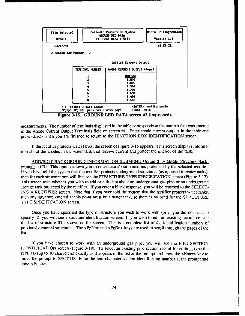
Fle Slecte Cathodic Protection Systen Micro CF )lagnostlcsGROM BED DATA
MCIN Ft. Hood flcNair Wit Version 1.1
OVIZ/91 15:52:3
Junction Box Number. 7
Initial Current Output
TERMIIL IMER ANODE CURRENT OUTFUT (Amps)
I EMz 1.0"3 1.004 1.5005 1.7986 1.6007 1.4009 1.s00
t I select / edit anode (ENTER) ottifU anode<PgUp> <?gDn> preolus - next page <ESC> quit
Figure 3-15. GROUND BED DATA screen #2 (impressed).
measurements. The number of terminals displayed in the table corresponds to the number that was enteredin the Anode Current Output Terminals field on screen #1. Enter anode current outputs in the table andpress <Esc> when you are finished to return to the JUNCTION BOX IDENTIFICATION screen.
If the rectifier protects water tanks, the screen of Figure 3-16 appears. This screen displays informa-tion about the anodes in the water tank that receive current and protect the interior of the tank.
ADD/EDIT BACKGROUND INFORMATION SUBMENU Option 2- Add/Edit Structure Back-3round: [C) This option allows you to enter data about structures protected by the selected rectifier.
If you have told the system that the rectifier protects underground structures (as opposed to water tanks),then for each structure you will first see the STRUCTURE TYPE SPECIFICATION screen (Figure 3-17).This screen asks whether you wish to add or edit data about an underground gas pipe or an undergroundstorage tank protected by the rectifier. If you enter a blank response, you will be returned to the SELECT-ING A RECTIFIER screen. Note that if you have told the system that the rectifier protects water tanks,then any structure entered at this point must be a water tank, so there is no need for the STRUCTURETYPE SPECIFICATION screen.
Once you have specified the type of structure you wish to work with (or if you did not need tospecify it), you will see a structure identification screen. If you wish to edit an existing record, consultthe list of structure ID's shown on the screen. This is a complete list of the identification numbers ofpreviously entered structures. The <PgUp> and <PgDn> keys are used to scroll through the pages of thelist.
If you have chosen to work with an underground gas pipe, you will see the PIPE SECTIONIDENTIFICATION screen (Figure 3-18). To select an existing pipe section record for editing, type thePIPE ID (up to 10 characters) exactly as it appears in the list at the prompt and press the <Enter> key tomove the prompt to SECT ID. Enter the four-character section identification number at the prompt andpress <Enter>.
74

rile Selected Cathodic Protection System Micro CP DiagnosticsGHCM BED DATA
MCARFt. Hood. McNair Vill Version 1.1
4/15/91 11:44:12
WATER TANX RECTIFIER Mo. Uali/Bol Anode StringsRectifier ID Mo. Anods/StringAnode Tqpe String Length (it)
Anode Manf acturer Mo. Anodes on Riser StringDesign Life (yrs) Riser String Length (ft)
Cable Gauge Anode Spacing (ft)Cable Insulation Type Anode-to-Wall Distance (ft)Ice Free Design? [V.l
Reference Electrodes:no. in Riser Location fHo. in Bowl Location
Figure 3-16. WATER STORAGE TANK ANODE DATAscreen (impressed).
File Selected Cathodic Protection System IMicro CF DiagnosticsSTRUCTURE TYPE SPECIFICATION
TANNS Tank Database Version 1.1
03,/,91 15 :45:99
Do you wish to work with a pipe section (P)or an underground storage tank (T)?
Please enter T or P: *
Figure 3-17. STRUCTURE TYPE SPECIFICATION screen (impressed).
75

[Fil 3electead Cathodic Protection Systen Mico Cr Diagnostica?n SECTIoI IDDITIFICATION
"C"Ok IM AFt. Hood NcKair Wit hers ion 1.1
04,IZ/1 15:53:2B
Enter FIPE ID:Enter SZCT ID: Of=
1.5 14 Z4 3
(PgU) <PgDn> previous / next page CESC) quit
Figure 3-18. PIPE SECTION IDENTIFICATION screen(impressed).
If you have chosen to work with an underground storage tank or a water tank instead of anunderground gas pipe, you will see the TANK IDENTIFICATION screen (Figure 3-19). Its operation issimilar to that of the PIPE SECTION IDENTIFICATION screen. It will only display existing tanks ofthe type you have chosen (either underground storage tanks or water tanks).
To select an existing tank record for editing, enter the TANK ID (up to 10 characters) exactly asit appears in the list of existing structures.
If you wish to create a new record (pipe or tank), type a new structure ID at the prompt, followingthe procedures given in the preceding paragraph for entering structure ID's. The program automaticallycreates a new record when a structure ID is entered that does not already exist in the program (i.e., doesnot appear on the list).
After you have entered the structure ID at the prompt, a screen will appear to allow you to addand/or edit background information about the structure. If the structure is a pipe, the ADD/EDIT PIPESECTION BACKGROUND DATA screen (Figure 3-20) will appear. If the structure is an undergroundstorage tank, the ADD/EDIT UNDERGROUND STORAGE TANK BACKGROUND DATA screen(Figure 3-21) will appear. If the structure is a water tank, the ADD/EDIT WATER TANK BACK-GROUND DATA screen (Figure 3-22) will appear.
You may now add or edit background information about the structure by typing the appropriateinformation at the corresponding prompts on the screen in the usual manner. If it is an undergroundstructure, one of the prompts is the question, "Do Isolation Joints Exist?" To answer the question, presseither <Y> (Yes) or <N> (No). If you press <Y> to signify that isolation joints do exist, the"ISOLATION JOINTS LOCATION" screen (Figure 3-23) will appear on your monitor.
The currently selected rectifier is automatically associated with a new structure. If the structure isprotected by more than one rectifier, you may wish to make this association in the CP database. Toassociate additional rectifiers with the structure, answer "Y" to the question "Do you wish to modify the
76

File Selected | Cathodic Protection System lcro CP DiagnosticsIATER TANK IDENTIFICATION
Ft. Hood MlcKair Uill [ ersion 1.1
64,15# 1 13:28:36
WATER TAM ID:
4001
<PgUp) <PgDn> preuious / next page (ESC> quit
Figure 3-19. TANK IDENTIFICATION screen (impressed).
File Selected Cathodic Protection System icro CF DiagnosticsADD.EDIT DACHGROUND DATA
flOAIR Ft. Hoo-c~air Vill ve-sion 1.1
6066,W91 10:53:S5
Pipe ID 4 Coating TypeSection Id = Coating QualitJ (ohms)Location From Coating Efficiency ()Location To Soil Resistivity (ohm-cm)Date Pipe Installled Section Length (ft)Date CP Activated Section Diameter (in)C? Installer Req. Current Density (aA/sq.ft)
Surface Area (sq.ft) .33Do Isolation Joints Exist? fl Total Current Required (A) S.4Z
Figure 3-20. ADD/EDIT PIPE BACKGROUND DATA screen(impressed).
77
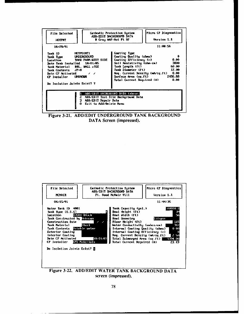
File Selected I Cathodic Protection System Micro CF DiagnosticsI DD/EDIT BACKROMID DA-T
HOTPNT R Gray AAF-Hot Pt Rt Version 1.1
le/z9/9111:00:56
Tank ID HOTPOINTI Coating TypcTank Type UNDERGROUND Coating Quality (olms) 0Location AtMN FARM-UEST SIDE Coating Efficiency (x) 0.00Date Tank Installed 101S Soil Resistluity (ohm-cA) 390Tank Material DBL. WALL aTEE Tank Length (ft) 60.09Tank Contents Jr-6 Tank Diameter (ft) 1Z.60Date CP Activated / Req. Current Density CNm/sq.ft) 0.00CP Installer LIKHQOUN Surface Area (sq.ft) 2486.88
Total Current Required (A) 0.00Do Isolation Joints Exist? Y
IZ ADD/EDIT Test Site Background Data3 ADD/EDIT Repair Data0 Exit to Add/Delete henu
Figure 3-21. ADD/EDIT UNDERGROUND TANK BACKGROUNDDATA Screen (impressed).
File Selected Cathodic Protection System Micra CP DiagnosticsADD/EDIT BACI(GRO(MND DATA
WZ?4A11 Ft. liood McNair Vill Version 1.1
04/IS/91 11:44,3S
Water Tank ID 401 Tank Capacity (gal.)Tank Type [ES.G] Bowl Height (ft)Location 0 Bc Boul Midth (ft)Tank Conitructed wn BBowl GeometryConstruction Date Riser Height (ft)Tank Material - ater Canductvity(unlscm)
Tank Contents a Internal Coating Quality (ais) IExterior Coating Internal Coating Erficiency (.)Interior Coating Req. Current Density (mA/sq.ft)Date CP Activated Total Submerged Area (sq.ft) /CP Installer Total Current Required (A) Z3.43
Do Isolation Joints Exist? M
Figure 3-22. ADD/EDIT WATER TANK BACKGROUND DATAscreen (impressed).
78

File Selected Cathodic Protection Systam Micro CP DiagnosticsADD.-EDIT BACXG OW DATA
MCMAIR Ft. Hood Kcf4ai Vill Version 1.1
eZ-ZS.9i 13:19:58
Pipe ID 4 I Coat ing Type Coal TarSection I& ZI Coating Quality (obs) 0Location From S. Gal/ Unit 155 Coating Efficiency (x) 0.00
Location To S. Gaff/ Unit 160 Soil Resistiuity (olin-cn) 4360Date Pipe Installed Z41/49Date CP Activated 86.41/85 ftmber Isolation LocationCF Installer Unknoun
0 1 BLDG. 1552 BLDG. 156
Do Isolation Joints Exist? y 3 BLDG. 1574 BLDG. 1585 BLDG. 1536 BLD6. 160
T I select / add location (ENTER) modif u location<PgUp> <PgDn> previous / next page (ESC> quit
Figure 3-23. ISOLATION JOINTS LOCATION screen (impressed).
list of rectifiers that help protect this pipe section/tank?" After you answer "Y", the rectifier ID popupwindow will appear. Enter the IDs of the additional rectifiers that protect the structure. (Note: Therectifier prompt and popup window are not shown in the figures below.)
ADD/EDIT BACKGROUND INFORMATION SUBMENU Option 3 - Add /Edit Test Site Back-ground. {C4) This option allows you to add or edit information about test sites that are associated withthe selected rectifier. After you select this option, select a structure in the usual manner. You must selectan existing structure; new structures cannot be created with this option. After a structure has beenselected, the TEST SITE IDENTIFICATION screen (Figure 3-24) appears. Select a test site from the listin the usual manner or create a new test site by typing a new test site ID at the prompt.
After you have selected a test site to work with, the ADD/ EDIT TEST SITE DATA screen #1(Figure 3-25) will appear. Enter the requested background information about the test site in the usualmanner. The ADD/ EDIT TEST SITE DATA screen #2 (Figure 3-26) appears after you press <Enter>on the last field of screen #1 or after you press <Esc> at any point in screen #1.
The TEST SITE DATA screen #2 asks you to enter several pieces of information related to themeasurement points of the test site. An "identifier" refers to any identifying characteristic of a test stationwire (such as color), a riser, or any other measurement point at a test site which will distinguish it fromthe other measurement points. The "Function" field is used to describe the reason for testing themeasurement point; an example entry for this field is "P/S 101," indicating that the pipe-to-soil potentialof pipe 101 may be read from the wire. Only initial structure-to-soil potentials are to be entered on thisscreen. Do not enter other potentials or anode currents. Fields are provided for the ON and INSTANTOFF potentials and the dielectric condition for each test taken. It is important to note that the initialpotentials entered here in the background data section are not evaluated when the Trouble Readings reportis run. These initial measurements provide baseline information only. The reports analyze data that isentered in the "Field Collection Data" section of the program.
Press <Esc> when all entries are complete and you will return to the TEST SITE IDENTIFICATIONscreen. If you wish to edit data for another test site associated with this structure, type its name at the
79

Iile Selected | Cathodic Protection System Micro Cr Diagnostics17ST SITE IDENTIFICATION
IC !11 Ft. Ho" Nflair Uill Version 1.1
04/15/91 13:45:29
Enter Test Site ED:
15515615715815916e
(Pglp) <PgD)n> preuious / next page (ESC> quit
Figure 3-24. TEST SITE IDENTIFICATION screen(impressed).
]rile Selected Cathodic Protection System micro ,F DiagnosticsADD/EDIT TEST SITE DATA
I1CA1N Ft. Hood Mlc~air 'Jill Version 1.1
0415/91 13:48:26
Pipe Identification 4 ZTest Site ID 155
Locat ion "DescriptionVendorSurface or Flush Mounted? (ISrlTools RequiredNatural Potential (volts)Intf. Dond Resistance (ohms) aDoes interference Exist?Shunt Resistor Value (ohms)Number of WiresComments
Figure 3-25. ADD/ EDIT TEST SITE DATA screen #1
(impressed).
80

File Selected I Cathodic Protection Sjstex Micro CF DiagnosticsI ADD/EDIT TEST SITE DATA
MCiAIR Ft. Hood -ciair U Vioersion 1.1
66/ 06.i 16:46:36
Test Site ID: 155
Measurement Point Initial Potentials (-U)
NO. IDENTIFIER FUIICTION (311 INSTANT OFF DIELECTRIC
t I select , edit uire <ENTER mmdifg wire<PgUp) <PgDn> preulous / next page <ESC> quit
Figure 3-26. ADD/ EDIT TEST SITE DATA screen #2-initial potentials (impressed).
prompt. If you do not wish to edit data for anaother test site associated with this structure, press <Esc>to return to the ADD/ EDIT BACKGROUND INFORMATION submenu.
A DD/EDIT BACKGROUND INFORMATION SUBMENU Option 4 - Add/Edit Structure RepairLog. (C5) This option allows you to enter information regarding repairs of a cathodically protectedstructure. After you select this option, select a structure in the usual manner. After you select a structure,a pop-up screen appears at the bottom of the ADD/EDIT BACKGROUND DATA screen (Figure 3-27),prompting you to enter the repair information regarding the selected structure. After you enter all therepair information for this screen, the program will replace the pop-up screen with the ADD/EDIT BACK-GROUND INFORMATION submenu.
ADD/EDIT BACKGROUND INFORMATION SUBMENU Option 0- Exit to Add/Delete Menu.This option will return you to Impressed Current Cathodic Protection Diagnostic's ADD/ MODIFY/DELETE menu.
ADD/MODIFY/DELETE MENU Option 2 - Add/Edit Field Collection Data (B2)
The ADD/EDIT Field Collection Data option allows you to enter potentials, anode currents, andrectifier readings each time they are gathered in the field. These are the measurements that will beevaluated by the analytic reports. After you select this option, the ENTER ADD/EDIT PASSWORDscreen (Figure 3-9) will appear. Type your ADD/EDIT password at the prompt and press <Enter>. Thepassword will not be displayed a- you type it. After you have entered the password correctly, the FIELDCOLLECTION MENU (Figure 3-28) fB3) will appear. Select the option that you wish to perform in theusual manner.
FIELD COLLECTION SUBMENU Option I - Add/Edit Test Site Field Data. {B4) This optionallows you to enter structure-to-soil potentials that have been measured at specific test sites during fieldtesting of the cathodic protection system. After you select this option, select a structure in the usualmanner. Alter you have selected a siijcture, the TEST SITE IDENTIFICATION screen (Figure 3-24)
81

file Selected Cathodic Protection Sy~stem Mlicro CP DiagnosticsAWDEDIT BACKGROUND DATA
MCNAIR Ft. Hood McNair Uill Iera ion 1.1
04/lZ/91 15:54:59
Pilpe ID 1.5 Coating TypeSecionIIICoating Quality (ohms)
Location From Coating Ericicency (Y)Location To Soil Resistiuity (ohm-cm)Date Pipe Insta lied I I Section Length (ft) TDate CP Actiuated Section Dialeter (in) DoCP Installer Req. Current DensitU (mA/sq.ft) I I
Enter Date of Repair II 0-I= REPAIR LENGTHmuddJy TOTAL COST
Figure 3-27. REPAIR DATA screen (impressed).
File Selected Cathodic Protection System Mi cro CF DiagnosticsFIELD COLLECTION MNtU
tCIR Ft. flood fc~oir Vill Version 1.1
04/17/91 09 :03 :SS
Z AddFEdit Rectifier Field Data0 Exit to Add/Delete Ienu
Menu Assistance
Press the number or your selection or use the It keys and [Enter].lEse] Ewlt Menu
Figure 3-28. FIELD COLLECTION MENU screen
(impressed).
82

appears and displays the test sites that are associated with the selected structure. Select a test site in theusual manner. You will be prompted to enter the date that the data was collected (Figure 3-29). Typethe date, or press <Enter> to use the current date. Next, type collection comments at the prompt and press<Enter> when done. The data table will then appear (Figure 3-30). Note that only structure-to-soilpotentials are entered in this table. Do not enter anode current outputs or other potential measurements.Select a measurement point by moving the pointer (on the left side of the screen) to it and pressing<Enter>. Type the data and press <Enter>. The pointer will move to the next line of the table. Whenyou are finished entering data, press <Esc> to return to the TEST SITE IDENTIFICATION screen. If youwish to enter data for another test site associated with this structure, type its ID at the prompt. If you donot wish to enter data for another test site associated with the structure, press <Esc> to return to theFIELD COLLECTION MENU.
FIELD COLLECTION SUBMENU Option 2 - Add/Edit Rectifier Field Data. {B5) This optionallows you to enter field measurements of rectifier operating parameters and anode current outputs. Afteryou select this option, the SELECTING A RECTIFIER screen (Figure 3-10) appears. Select the rectifierfor which you wish to enter data in the usual manner. The ADD/ EDIT RECTIFIER FIELD DATAscreen (Figure 3-31) will appear.
Enter the data requested in the usual manner. When you are finished entering data, press <Enter>on the last field of the screen or press <Esc> at any field. The JUNCTION BOX IDENTIFICATIONscreen (Figure 3-13) will appear. Select the junction box that you wish to work with in the usual manner.The ANODE CURRENT OUTPUT screen will appear. Enter the data collection date and collectioncomments at the prompts. Press <Enter>. The rest of the screen, which contains the anode current outputtable, will appear (Figure 3-32). Select the terminal for which you wish to enter data by moving thepointer (on the left side of the screen) to it and pressing <Enter>. Type the data, then press <Enter>. Thepointer will move to the next line of the table. When you are finished entering anode currents, press<Esc> to return to the FIELD COLLECTION MENU.
File Selected Cathodic Protection System M ficro CF DiagnosticsTEST SIATIOIIPOINT IDEITIFICATION
tICAIH Ft. Hood MlcNair Vill Vcrslon 1.1
03-o.04/91 16:23:31
Test Station/Point ID: 155 Collection Date: 03.441
Figure 3-29. TEST SITE COLLECTION screen(impressed).
83

File Selected I Cathodic Protection Syjstem Micro CF DiagnosticsI TEST SITE IDENTIFICATION
MCNAIR Ft. Hood McNair Vill Version 1.1
6.06/91 10:40:58Field Potential Measurements for
Test Site ID: 155 Collection Date:Collection Comients:
Measurenent Point Field Potentials (-U)
MO. IDENTIFIER FIJUCTION Om INSTANT OFF DIELECTRIC
I RISER P/S la I= MAsi
T I select / edit uire (ENTER) modifg uire(PgUp> <PgDn> preulous / next page (ESC> quit
Figure 3-30. TEST SITE COLLECTION screen #2 (impressed).
File Selected Cathodic Protection System fMicro CP DiagnosticsADD/EDIT RECTIFIER FIELD 'DATA
CHMAIJ Ft. Hood icHair Viii Version 1.1
06.06,91 10:47,17
Rectifier ID 1Collection Date 06/06/31Corwents; _ Operating ode
Rheostat SettingAutomatic Set Point
CIRCUIT 1 CIRCUIT 2 CIRCUIT 3Tap Settinq
Fine:CoArse:
DC Voltage (U): sDC Current (A): I IAC Voltage (V):AC Current (A):Circuit Resistance (olh.): 0.68 0.00 0.00Rectifier Erficiency (): 76.53 0.00 0.00
Figure 3-31. ADD/ EDIT RECTIFIER FIELD DATA screen(impresed).
84

File Selected I Cathodic Protection System Micro C? DiagnostirsIJUNlCTION BOX IDEN4TIFICATIONl
ICMA I I Ft. Hood McNair Ujill Version 1.1
e4/z/91 15:56:49Anode Current Output Field Data for
Junction Box Number: 7 Collection Date;Collection Cowments:
TERMINAL NIMBER ANODE CURRENT OUTPUT (Amps)
2 1.9003 1.0004 1.5005 1.7006 1.6007 1.1000 1.500
t I select / edit anode (ENTER)- modify anode<l'gUp) <PgDn> preulous , next page (ESC) quit
Figure 3-32. ANODE CURRENT DATA screen (impressed).
FIELD COLLECTION SUBMENU Option 0-Exit to ADD/MODIFY/DELETE menu. This optionreturns you to the ADD/MODIFY/DELETE menu.
ADD/MODIFY DELETE MENU Option 3 - Delete Structure/Rectifier/Test Site Data (B6}
This option allows you to delete the rectifier, structure, and test site records from the currentlyselected database. After you select this option, the password screen (Figure 3-33) will appear. Enter yourpassword at the prompt. The password will not be displayed on the screen as you type it. After you haveentered your password, the program will display the DELETE MENU screen (Figure 3-34) {B71. Selectthe operation that you wish to perform in the usual manner.
DELETE MENU Option 1 - Delcte Rectifier Data. {B8 This option allows you to permanentlydelete a rectifier and all of the associated structure and test site records from the database.
WARNING: USE THIS OPTION WITH EXTREME CARE. THIS OPTION DELETESTHE RECTIFIER FROM THE RECTIFIER DATA BASE AND DELETES ALL ASSOCI-ATED TEST SITE RECORDS. ONCE DELETED, THEY CANNOT BE RECALLED!
When you select this option, the program will display the SELECT A RECTIFIER screen (Figure 3-10).Type the ID of the rectifier that you wish to delete at the prompt and press <Enter>. The DELETERECTIFIER DATA screen (Figure 3-35) will appear.
To delete the rectifier records corresponding to the displayed rectifier ID, answer the prompt in thesubmenu with <Y> (Yes). If, however, you do not wish to delete the rectifier records and all associatedtest site records, press <N> (No).
The lower right-hand comer of the screen displays an additional warning. As stated above, pleasecarefully consider deletion of the rectifier information from the data base. ONCE DELETED, THISINFORMATION CANNOT BE RECALLED.
85
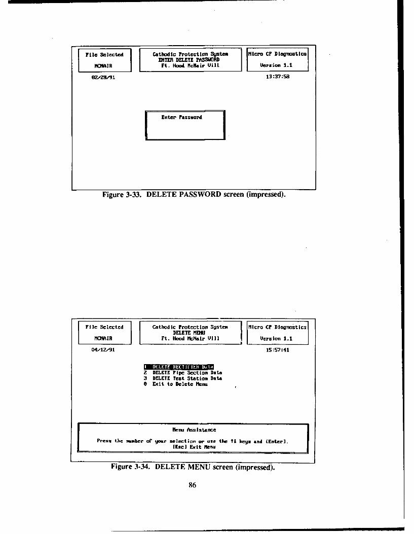
Ile Seletd Cathodic Protection Sjten Micro Ci Diagnostics
ZHETER DELETE PA33WORDCMAIR Ft. Hood Ncftair Uill. Uersion 1.1
6Z#ZS/S1 13:37:58
Enter Pass word
Figure 3-33. DELETE PASSWORD screen (impressed).
File Selected Cathodic Protection SUstev Micro CF DiagnosticsDELETE MENU
"CHAIR Ft. Hood McNair Vill Version 1.1
0441914 15:57:41
IM I ll a afI iIa IIIMIaGZ DELETE Pipe Section Data3 DELETE Test Station Data0 Exit to Delete le=t
hi.nu Assistance
Press the nmLer or gour selection or use the ?1 kets and (Enter].(Esc] Exit lMenu
Figure 3-34. DELETE MENU screen (impressed).
86

Fie elctdCathodic Protection System Micro CF Diagnostics
File I DELETE RECTIFIER DATAMCNA IR Ft. Hooda PMe~ir Ujill Version 1.1
06/05/91 10:49:56
R-ctif ier ID 7
Rectifier Location Humber of FusesRectifier Type Fuse Rating (A)Rectifier hamaf. Humber of CircuitsRectifier Model O[perating ModeDC Rated Uoitage (U) init. Rheostat Setting goDC Rated Current (A) Inilt. Automatic (set point)Ref. Electrode Pot. (V) Protected Structures iMAJI 0
Delete Rectifier ID? This option DELETES the Rectifier IDfrom the Rectifier database and ALL
Field Collection records.
(Y/IH) Is this uhat you wish to do?
Figure 3-35. DELETE RECTIFIER DATA screen (impressed).
After you have performed this task, the program automatically returns to the DELETE MENU.
DELETE MENU Option 2 - Delete Structure Data. {B9) This option enables you to delete allrecords associated with a structure. Select a structure in the usual manner. The program will thengenerate the DELETE STRUCTURE DATA screen (Figure 3-36).
ONCE AGAIN, USE THIS OPTION WITH EXTREME CARE. THIS OPTION DELETESTHE STRUCTURE INFORMATION FROM THE APPROPRIATE STRUCTURE DATABASE AND DELETES ALL ASSOCIATED TEST SITE RECORDS. ONCE DELETED,THIS INFORMATION CANNOT BE RECALLED.
To delete the structure records corresponding to the displayed structure ID, respond to the promptin the pop-up screen with <Y> (Yes). If you do not wish to delete the structure records, and all associatedtest site records, press <N> for No.
An additional warning is posted in the lower right-hand comer of the screen. Please carefullyconsider deletion of the structure information. ONCE DELETED, THIS INFORMATION CANNOT BERECALLED.
After performing this task, the program returns to the DELETE MENU.
DELETE MENU Option 3 - Delete Test Sitc Data. [BI0) By selecting the DELETE MENU'sOption 3, you are able to delete all records associated with a specific Test Site.
USE THIS OPTION WITH EXTREME CARE. THIS OPTION DELETES THE TEST SITEINFORMATION FROM THE TEST SITE DATA BASE. ONCE DELETED, THISINFORMATION CANNOT BE RECALLED.
87

[ileSelect Cathodic Protection System Micro C? DiagnosticsI I DELETE PIFE SECTIOI DATA
IFt. Hooa-McKair Ujil Version 1.1
66,,0/91 10:55:04
Pipe ID 4 Coating Type Coal tarSection 1d 2 Coating Quality (alas) 0Location From S. Gai./ Unit 155 Coating Efficiency () 0.00Location To S. Gafi/ I lt 160 Soil Resistluity (ohm-cm) 4360.Date Pipe Installed SZ/81/49 Section Length (ft) 200.86Date CP Actiuated 681/85 Section Diameter (in) 4.00CP Installer Unknomn Req. Current Density (nf/sq.ft) Z.00
Surface Area (sq.ft) 209.33Do Isolation Joints Exist? Total Current Required (A) 0.42
Delete Pipe ID I This option DELETES the ripe Section
Section # Z from the Pipe database A ALL associatedTest Site rcords.
U(YAI) Is "Ltis uhat you wish to do7
Figure 3-36. DELETE STRUCTURE DATA screen (impressed).
Select a structure in the usual manner. After you select a structure, the program will display theTEST SITE ID screen (Figure 3-24). Select the test site whose records you wish to delete by typing itsID at the prompt and press <Enter>. The ICP program will then display the DELETE TEST SITE DATAScreen (Figure 3-37).
To delete the Test Site records corresponding to the displayed Test site ID, respond to the promptin the pop-up screen with a <Y> (Yes). If you do not wish to delete the Test site records from the database, as well as all associated field collection records, press <N> (No).
Again, as with other deletion options, you will notice that at the lower right-hand comer of yourscreen an additional warning is posted. Please consider deletion of the Test site information carefully.ONCE DELETED, IT CANNOT BE RECALLED.
After you have performed this task, you will be automatically returned to the DELETE MENU.
DELETE MENU Option 0 - Exit to ADD/MODIFY/DELETE Menu. This option returns you tothe ADD/MODIFY/DELETE menu.
MAIN MENU Option 2 - Data Base-Related Reports {A4}
When you select this option, the REPORT MENU (A5} will appear. To generate a report, selectit from the menu and respond to the prompts. Many of the reports are displayed to the printer only, somake sure that your printer is on and loaded with paper. If you did not already configure CP Diagnosticfor your printer by entering the printer control strings on the System Utility screen, be sure to do so beforeattempting to generate any reports. The reports that can be generated are explained below.
88

File Selected I Cathodic Protection System Mlicro CF DiagnosticsIDELETE TEST STATION-POINT DATA
i CHAIR Ft. Hood McNir Ui Version 1.1
ez/z8,9i 13:42:44
ripe Identification ITest Station/Point ID 155
Location BLDG. 155Description RISER TEST POINTUendor MASurface or Flush Mlounted? [/F]Tools Required NMNatural Potential (volts) 0.600Intf. Bond Resistance (ohms) 0.00Does Interference Exist?
Delete Test Station/Point This option DELETES the Test Station
155 or Point from the database A ALLField Collection records.
M
(VAN) Is this what you wish to do?
Figure 3-37. DELETE TEST SITE DATA screen (impressed).
REPORT MENU Option I - Field Collection Forms (DI)
This report prints a series of field data collection forms that can be used by the field inspector. Adata collection form lists all test sites associated with a structure, and contains a description of each testsite. The forms also list each rectifier with its associated junction boxes. The forms can be used to collectpipe-to-soil potentials at the test sites, anode current outputs at the junction boxes, and rectifier readings.Data may then be entered into Impressed Current CP Diagnostic from the data collection forms. To gene-rate the report, select it from the menu. The inspection forms will begin printing as soon as the optionis selected from the menu. After the report has printed, you will be returned to the REPORT MENU.
REPORT MENU Option 2 - Trouble Readings Report (D2)
This report identifies all test sites with readings that do not meet the selected criterion for propercathodic protection. To generate the report, select it from the menu and enter the earliest date that youwish the readings to be analyzed at the prompt. Select the criterion that you wish to use from the CPCRITERION MENU (Figure 3-38). The criterion should be selected with extreme care. See Chapter 1for a detailed discussion and guidance on this subject. The report will begin printing as soon as you selectthe criterion. The report prints every reading taken after the specified date that does not meet the selectedcriterion.
REPORT MENU Option 3 - Structure Listing [D3}
This report provides a listing of all structures in the data base. It gives the structure ID and location.It is useful as a concise description of the overall structure inventory. To generate the report, select itfrom the menu. You will LU presented with a screen that asks whether you wish to send the report to the[Sicreen, [PIrinter, or [Qluit. Press the first letter of the option you wish to select. Printer [P] is thedefault option and may be selected by pressing <Enter>. If you choose to display the report on the screen,press the <Cntl> and <S> keys to stop or start the scrolling of the data that is being displayed. Press anykey after the report has been displayed on the screen to return to the REPORT MENU. If you select[Qluit, you will be returned to the REPORT MENU and the report will not be generated.
89

File Selected I Cathodic Protection System Micro CF DiagnosticsTROUBLE READItGS REPORT
MCHAIR Ft. Hood lcNair Uill Uersion 1.1
606/91 10:40:01
Please select the cathodic protectioncriterion that you wish to use.
Z 360 hllliuott Shift Criterion3 10 lil1luolt Shift Criterion1 -0.85 Volt Instant-Iff-Potential Criterion5 User-Specified On-Potential Range0 EXIT Uithout Printing Report
Figure 3-38. CP CRITERIA MENU screen (impressed).
REPORT MENU Option 4 - Structure Master Listing (D4)
This report displays the background information for each structure recorded in the data base,providing a more detailed description of the structures than the Structure Listing (Report 3). To generatethis report, select it from the menu and respond to the [Sicreen, [P]rinter, or [Q]uit prompt as describedabove for the Structure Listing report. If you choose to display the report on the screen, press the <Cntl>and <S> keys to stop or start the scrolling of the data that is being displayed. Press any key after thereport has been displayed on the screen to returnto the REPORT MENU. If you select [Q]uit, you willhe returned to the REPORT MENU, and the report will not be generated.
REPORT MENU Option 5 - Field Collection Report (D5}
This report gives a complete listing of all field data (arranged by test point) collected at all test sitesduring a user-specified time period. The listing includes dates, potentials, and dielectric status for eachtest point. To generate the report, select it from the menu, and it will begin printing immediately. Afterthe report is printed, you will be returned to the REPORT MENU screen.
REPORT MENU Option 6 - System History Report (D6)
This report lists dates and descriptions of repairs that were performed and dates and locations thatfield measurements were taken for all structures throughout the life of the system. The listing is inchronological order. To generate the report, select it from the menu and it will begin printingimmediately. After the report is printed, you will automatically be returned to the REPORT MENUscreen
REPORT MENU Option 7 - Test Sites Not Collected Report (D7)
This report prints the identifiers of all test sites from which field data has not been collected overa specified range of time. To generate the report, select it frori the menu and enter the desired range ofdates at he prompt. To keep the default (current) date, simply press <Enter>. Respond to the [Sicreen,
90

[PIrinter, or [Q]uit option as discussed above. You will be returned to the REPORT MENU after the
report is printed.
REPORT MENU Option 8 - Repair History Report (D8}
This report prints the contents of the repair database including repair date, failure type, repair length,and cost of repair. The repairs are listed by year, and annual repair costs are totalled. This report can beprinted for structure or for all structures in the database. To generate the report, select it from the menu.At the prompt, enter a structure ID if you wish to print the report for one structure only, or enter "ALL"if you wish to print the report for all structures in the database. Press <Enter> after you type yourselection, and the report will be printed. You will be returned to the REPORT MENU after the report isprinted.
REPORT MENU Option 9 - Anode Current Output Drop Report [D9}
This report identifies the rectifier, junction box, and anode current output for any anode currentterminal that has experienced a drop in the anode current output over time. A significant drop in anodecurrent output is defined to be a drop of at least 10 percent between any two readings (they need not beconsecutive) or a drop of any amount over three consecutive readings (that is, two consecutive drops ofany amount). To generate this report, select it from the menu and enter the earliest and latest readingdates that you wish the report to consider. The report will print immediately after you enter the dates, andyou will be returned to the REPORT MENU after the report is printed.
REPORT MENU Option 10 - Rectifier Master Listing (DIO)
This report prints the background information for each rectifier recorded in the data base.
REPORT MENU Option 11 - Rectifier History Report (DI1)
This report prints all field collection data recorded for each rectifier. The user may specify a rangeof dates for the report. The report provides only field measurements collected during the requested rangeof dates.
REPORT MENU Option 0 - Return to Main Menu
This option returns you to the Main Menu screen of Impressed Current CP Diagnostic.
91

REFERENCES
Cathodic Protection Computer System Impressed Current Field Investigation (HARCO Technologies, Inc., Medina, OH, July1989).
Cathodic Protection Module at Fort Riley, Kansas (Corrpro Companies, Inc., Schaumburg, IL, 28 February 1989).
"Cathodic Protection System (Sacrificial Anode)," Guide Specification for Military Construction, Electrical, Section 16640 (U.S.Army Corps of Engineers [USACE], December 1988).
"Cathodic Protection System (Impressed Current)," Guide Specification for Military Construction, Electrical, Section 16642(USACE, March 1989).
"Cathodic Protection System (Steel Water Tanks)," Guide Specification for Military Construction, Electrical, Section 16641(USACE, February 1989).
"Control of External Corrosion on Underground or Submerged Metallic Piping Systems," Recommended Practice RP-01 -69, 1983revision (National Association of Corrosion Engineers [NACE]. Houston, TX, 1983).
"Control of External Corrosion on Metallic Buried, Partially Buried, or Submerged Liquid Storage Systems," RecommendedPractice RP-01-85 (NACE, 1985).
Electrical Design, Cathodic Protection, Technical Manual (TM) 5-811-7 (Headquarters, Department of the Army [HQDA], April1985).
Guglomo, R., et al., GRIPER Implementation Guide and User Manual, Draft Technical Report (U.S. Army ConstructionEngineering Research Laboratory [USACERL], 1990).
Husock, B., Evaluation of Cathodic Protection Criteria, ESL TR-79-14 (Headquarters, Air Force Engineering and Services Center[HQAFESCJ, Tyndall Air Force Base, FL, April 1979).
Kumar, Ashok, Margaret Blyth, and Michael Bergenhouse, "Implementation of a Pipe Corrosion Management System,"Proceedings of the National Association of Corrosion Engineers (NACE, San Francisco, 1987).
Maintenance and Operation of Cathodic Protection Systems, Air Force Manual (AFM) 85-5 (Headquarters, U.S. Air Force, 1982).
Myers, J.R., Cathodic Protection Acceptance Criteria: A Guide for Directorate of Engineering and Housing (DEH) Inspectors,Contractor Report (USACERL, 1988).
UNCITED REFERENCES
Cathodic Protection-Measurement Principles (NACE. 14 November 1986).
Myers, J.R.. and M.A. Aimone. Corrosion Control for Underground Steel Pipelines: A Treatise on Cathodic Protection (AirForce Institute of Technology, 1977).
92

APPENDIX A: Sample Implementation Specification for Sacrificial CP Diagnostic
OVERVIEW
This Appendix contains an example of a scope of work that may be used by an Army installationwishing to utilize a contractor for the implementation of Sacrificial CP Diagnostic. Words that are in[bold print and brackets] indicate site specific data to be inserted by the installation. This Appendix isonly intended to be a guide for the technical content of the scope of work. Each installation may wishto add, change, or delete sections or use a different format depending upon its typical contractingprocedures.
Maps are referred to throughout the specification. These maps are to be supplied by each installationas an attachment and are not included in this publication.
The remainder of Appendix B contains the complete sample implementation specification.
SPECIAL NOTE: The Army Technical Manual referred to in Paragraph 1.1.4 of the specificationwas in publication and had not been released at the time that this manual was written. Until it is released,references to it should be deleted from this specification. Such references will appear in [brackets).When it is released, insert the number in place of the question marks given in each bracketed reference.
93

SCOPE OF WORK
IMPLEMENTATION OF SACRIFICIAL CP DIAGNOSTICAT
[INSTALLATION'S NAME]
1.0 GENERAL
1.1 APPLICABLE PUBLICATIONS
The publications listed below form a part of this specification to the extent referenced. Thepublications are referred to in the text by basic designation only.
1.1.1 U.S. Army Construction Engineering Research Laboratory (USACERL)
USACERL ADP Cathodic Protection DiagnosticReport M-91/24 Computer Program for Sacrificial
and Impressed Current Systems:Overview and User's Manual
1.1.2 Headquarters, Department of the Air Force
Air Force Manual Maintenance and Operation ofAFM 85-5 Cathodic Protection Systems9 February 1982
1.1.3 National Association of Corrosion Engineers
NACE Standard Recommended Practice,RP-01-69 Control of External CorrosionJanuary 1983 revision on Underground or Submerged
Metallic Piping Systems
NACE Standard Recommended Practice,RP-02-85 Control of External CorrosionMarch 1985 on Metallic Buried, Partially
Buried, or Submerged LiquidStorage Systems
1.1.4 Headquarters, Department of the Army)
[Technical Manual (Operation and MaintenanceTM 5-??? of Cathodic Protection(This document had not Systems)yet been released when thismanual was published))
94

1.2 SYNOPSIS OF WORK
The Contractor shall furnish all materials and perform all services required to implement theSacrificial Cathodic Protection (CP) Diagnostic computer program as set forth in these detailedspecifications for [installation's name]. Approximately [insert number] linear feet of "ndergroundpiping and 'insert number] underground storage tanks are to be included. These structures are shownon the maps in Appendix III of this specification. CP Diagnostic maintains background information andfield test data about cathodic protection systems and the structures that they protect and generates reportsthat assist in pinpointing system malfunctions. Work shall be accnmplished in accordance with thepublications cited in section 1.1, except as modified elsewhere in these specifications. The following itemsof work, explained more fully in Sections 2.0 through 6.0, are included:
1.2.1 Inventory and Initial Field Testing: Establish an identification system for the specifiedunderground pipes, underground storage tanks, and test sites as directed in the CP Diagnostic UserManual. Fumish reproducible mylar maps showing the pipe network, tanks, and test sites with all of theidentification numbers clearly marked. Collect and record all of the reonired background data for eachstructure and test site, initial structure-to-soil potentials, initial anode current outputs, and dielectricconditions as explained under Section 2.0, Inventory.
1.2.2 Data Entry: Enter all data into the CP Diagnostic program and provide a complete databaseand an error-free run.
1.2.3 Generation of Reports: Furnish computer printouts of the reports specified in Section 4.0.These reports show the information input into the data base and pinpoint possible problems in the cathodicprotection system. Include these the final report, along with a discussion of the results. Providerecommendations where applicable.
1.2.4 Training: Provide training to DEH personnel on the CP Diagnostic system set-up and use.
1.2.5 Preparation of Final Report: A final report as discussed in Section 6.0 shall be prepared witha formal narrative section describing the work and method of accomplishment. All data and program-gcnerated reports shall also be included. The final report shall be presented to the DEH at an exit briefing.
1.3 PROJECT MANAGEMENT
1.3.1 Proiect Supervisor: The supervisor shall serve as a single point of contact and liaison for allwork required under this Contract. Upon award of the Contract, this individual and an alternate shall beimmediately designated in writing by the Contractor. These designated individuals shall be approved bythe Government Project Engineer. One of these individuals shall be available at the installation wheneverthe Contractor is performing work under this Contract.
1.3.2 Installation Assistance: A duly authorized represcntative from within the Directorate ofEngineering and Housing will serve as the point of contact for obtaining available information andassisting in establishing contacts with the proper individuals and organizations, as necessary, in theaccomplishment of the work required under this Contract.
1.3.3 Public Disclosures: The Contractor shall make no public announcements or disclosuresrelative to information contained or developed in this Contract, except as authorized by the ContractingOffice.
95

1.3.4 Conferences: Conferences shall be scheduled as shown on the Implementation Schedule basedon work status or whenever requested by the Contractor or Government Project Engineer for the resolutionof quest ions or problems encountered in the performance of the work. The Contractor shall be requiredto attend and participate in all conferences pertinent to the work as directed by the Contracting Officer.
1.3.5 Qualifications of Personnel: Field inspections shall be performed by technically trainedpersonnel under the direct supervision of a National Association of Corrosion Engineers (NACE)-accredited Cathodic Protection Specialist OR a NACE-accredited Corrosion Specialist with a specialty areaof Cathodic Protection. All data and the final report shall be, at a minimum, reviewed and signed by aNACE-accredited Cathodic Protection Specialist OR NACE-accredited Corrosion Specialist wi;' ,specialty area of Cathodic Protection.
1.3.6 Scheduling: At the beginning of the contract period, the Contractor shall submit animplementation schedule using the format shown in Appendix II of this specification for approval by theGovernment Project Engineer. Detailed schedules for field work will be coordinated through theGovernment Project Engineer each week. In-progress reviews should be scheduled as follows:
• At the completion of establishing the structure and test site identification in the office and priorto proceeding with any field work.
" At the completion of the field survey data input." At the final exit briefing during the presentation to the DEH of the complete CP Diagnostic
system.
Incremental Contractor checked data shall be furnished to the government as required by the GovernmentProject Engineer for review and concurrence.
1.4 PAYMENT
1.4.1 Overhead, Supervision, Site Visits and Inspection: All overhead, supervision, travel costs,and other expenses to be incurred by the Contractor, directly or indirectly, including costs of the site visitsthroughout the work, shall be included in the proposal under the work items described. These costs shallnot be considered separately.
1.4.2 Monthly Payment, Lcss Deductions: The Contractor shall be paid, upon the submission ofproper invoices or vouchers, the prices stipulated in the proposed schedule rendered and accepted, lessdeductions, if any, as herein provided. Unless otherwise specified, payment will be on performanceaccepted by the U. S. Government when the amount due on such performance so warrants. Payment maybe requested not more than once each month.
1.4.3 10 Percent Retention: In making such payments, the U.S. Government may, at its option,rctain 10 percent of the estimated amount until final completion and acceptance of the Contract work.lowcvcr, if the U.S. Government, at any time after 50 percent of the work has been completed, finds that
satisfactory work is being performed, it may authorize any of the remaining payments to be made in full.When the work is substantially complete, if the Government considers the amount to be retained in excessof the amount adequate for the protection of the U.S. Government, the Government may, at its discretion,rclcase to the Contractor all or a portion of such excess amount.
1.4.4 Final Payment on Release: Upon completion and acceptance of all work, the amount due theContractor under this Contract is dependent upon the presentation of a properly executed voucher after
96

the Contractor has furnished the U.S. Government with a release, if required, of all claims against the U.S.Government arising by virtue of this Contract, other than claims in stated amounts as may be specificallyexpected by the Contractor from the operation of the release. If the Contractor's claim to amounts payableunder this Contract has been assigned under the Assignment of Claims Act of 1940, as amended (31U.S.C. 203, 41 U.S.C. 15), a release may also be required of the assignee.
1.5 SAFETY
The Contractor shall conduct operations in a safe manner at all times. Safety provisions shall beconsistent with the Army Corps of Engineers Safety Manual. The Contractor's operation shall not causea potential safety hazard to occupants of the area, Contractor's and U.S. Government personnel, and U.S.Government property.
1.6 CONTRACTOR & INSTALLATION WORK HOURS
The normal hours of operation at the installation will be between [insert hours] Monday throughFriday except on the following Federal holidays:
New Years Day President's DayMemorial Day 4th of JulyLabor Day Veterans DayThanksgiving ChristmasMartin Luther King Day Columbus Day
Field work in Family Housing areas shall be conducted during the hours of [insert hours]. Other siteconditions or security requirements may necessitate that the required field work be performed outside ofthe normal hours of operation.
1.7 ACCESS TO RESTRICTED AREAS
The list of structures and test sites which are in restricted areas, and the procedure to obtain accessto these areas is as follows: [insert list of structures/ test sites and access procedures]
1.8 CONTRACT DURATION
The Contract completion date shall be [insert number] calendar days after the Notice to Proceedhas been received by the Contractor.
1.9 POINTS OF CONTACT
1.9.1 Directorate of Engzineering and Housing Point of Contact: [list name(s) here]
[INSERT OTHER ORGANIZATIONS AND POINTSOF CONTACT HERE AS APPLICABLE]
97

2.0 INVENTORY AND INITIAL FIELD TESTING
2.1 GENERAL
A complete description of the inventory and field test data requirements for CP Diagnostic is givenin the USACERL report "Cathodic Protection Diagnostic Computer Program for Sacrificial and ImpressedCurrent Systems: Overview and User's Manual." This publication will be referred to as the CPDiagnostic User's Manual throughout the remainder of this specification. The Contractor shall utilizeinstallation drawings and records, perform field surveys, conduct interviews with DEH personnel, andassemble other information as necessary to gather the required data. The Contractor shall m-ake areasonable effort to obtain 100 percent of the required data. If any part of the required data cannot becollected, the Contractor shall submit in writing a complete list of the unavailable data, along with areason for its unavailability. The reason must be approved by the Contracting Officer before the databasewill be accepted as "error-free" as discussed in Section 3.0. A complete listing and explanation ofunavailable data shall also be given in the final report. The Contractor shall copy blank forms from theCP Diagnostic User's Manual or other reference as necessary to perform work and submit with the finalreport as specified by this Contract.
2.2 DEFINITION AND IDENTIFICATION OF PROTECED STRUCTURES
The Contractor shall define and set up an identification system for the network of protectedstructures as described in the CP Diagnostic User Manual. This shall be done in coordination with andshall be subject to approval by the DEH point of contact given in section 1.9. For an underground pipingsystem, this procedure involves dividing the system into a series of pipe sections, each with its own uniqueidentification number. For a system of underground storage tanks, each tank will be assigned its ownunique identification number. These structures shall be clearly identified on the reproducible mapsdescribed in 1.2.1.
2.3 COLLECTION OF STRUCTURE BACKGROUND DATA
The Contractor shall collect a complete set of background data as described in the CP DiagnosticUser's Manual for each structure (i.e., pipe section or tank) identified under paragraph 2.2. Thisinformation shall be collected on the Pipe Section Background Data Sheet and/or the Underground TankBackground Data Sheet provided in the CP Diagnostic User's Manual or a reasonable facsimile thereof.One form shall be completed for each structure. It is the Contractor's responsibility to reproduce theforms in sufficient quantities to collect data for the entire system. The following information is requiredfor each pipe section:
* Location from • Coating quality (ohms)" Location to • Coating efficiency (%)" Date installed • Soil resistivity (ohm-cm)* Date CP activated * Section length (ft)" CP installer - Section diameter (in)" Coating type • Required current density (mA/sq ft)" Locations of isolation
joints
98

The following information is required for each underground storage tank:
• Tank type * Coating type• Location • Coating quality (ohms)* Date tank installed • Coating efficiency (%)" Tank material - Soil resistivity (ohm-cm)" Tank contents • Tank length (ft)" Date CP activated - Tank diameter (ft)" CP installer * Required current density (mA/sq ft)" Locations of isolation
joints
2.4 DEFINITION OF CATHODIC PROTECTION SYSTEM
The cathodic protection system itself is defined as a series of "test sites" with their associated anodesor anode beds. A "test site" may either be a test station or any other test point at which potential orcurrent measurements are taken, such as a riser or a valve. Each test site is associated with a particularstructure. The Contractor shall define and set up an identification system for the test sites as describedin the CP Diagnostic User's Manual. This shall be done in coordination with and shall be subject toapproval by the DEH point of contact given in paragraph 1.9.
2.5 COLLECTION OF TEST SITE BACKGROUND DATA
The Contractor shall collect a complete set of background data as described in the CP DiagnosticUser's Manual for each test site identified under paragraph 2.4. This information shall be collected onthe Test Site Background Data Sheet provided in the CP Diagnostic User Manual or a reasonable facsimilethereof. One form shall be completed for each test site. It is the Contractor's responsibility to reproducethe forms in sufficient quantities to collect data for the entire system. The following backgroundinformation is required for each test site:
Structure ID • Natural potential (volts)" Location • Interference bond resistance (ohms)* Description • Does interference exist?" Vendor - Shunt resistor value (ohms)" Surface or flush mounted - Number of wires" Tools required - Comments
2.6 COLLECTION OF TEST SITE POTENTIAL MEASUREMENTS
For each potential measurement point of each test site identified in 2.4, the Contractor shall assignan identifier (such as wire color) and shall collect the following information:
" Measurement point identifier" Function of measurement point" "Connected" potential (volts)" "Disconnected" potential (volts)
If initial potentials (those that were taken when the CP system was installed) are available, they shall alsobe recorded on the data sheets.
99
................. .... . ~ lnn u~lu H

Potentials shall be measured using the procedures in AFM 85-5 {and/or Army TM 5-???). All of thecollected information shall be recorded on the Test Site Background Data Sheets that were prepared underparagraph 2.5.
2.7 COLLECTION OF DIELECTRIC CONDITION DATA
The Contractor shall determine the condition (i.e., good, shorted, etc.) of each dielectric fitting andshall record this information.
2.8 COLLECTION OF ANODE BACKGROUND DATA
The Contractor shall collect a complete set of background data as described in the CP DiagnosticUser's Manual for the anodes associated with each of the test sites identified under 2.4. This informationshall be recorded in Part II of the Test Site Background Data Sheets prepared under paragraph 2.5. Thefollowing information is required:
" Anode type • Design life (yrs)" Anode material • Anode spacing (ft)" Anode diameter (in) • Structure to anode distance (ft)" Anode length (in) • Structure to anode direction• Anode weight (lbs) - Cable gauge" Number of anodes • Cable insulation type* Number of anode current
output terminals
2.9 COLLECTION OF INITIAL ANODE CURRENT OUTPUTS
For each anode current output terminal of each test site identified in 2.4, the Contractor shallmeasure the anode current output in amperes. The measurements shall be recorded in Part II of the TestSite Background Data Sheets that were prepared under paragraph 2.5. If initial currents (those that weretaken when the CP system was installed) are available, they shall also be recorded on the data sheets.Currents shall be measured using the procedures in AFM 85-5 {and/or Army TM 5-???).
3.0 DATA ENTRY
3.1 GENERAL
The Contractor shall code for entry into CP Diagnostic all verified data collected from installationdrawings and records, field surveys, interviews, or other sources. Coding for the computer shall be inaccordance with the CP Diagnostic User's Manual. The result shall be a complete, error-free database.
3.2 DATA ENTRY
The Contractor shall enter data into the database on a Government-owned microcomputer. TheGovernment shall provide a copy of the CP Diagnostic program for the Contractor's use. The Contractorshall ensure and verify that the data stored in the database corresponds with the field data. Care shall betaken to ensure that data input into the database follows a sequence that avoids duplication or omissionsand provides as a finished product an error free, complete database ready for CP Diagnostic operations.
100

3.3 INITIAL DATA CHECKING
The structure and test site identification information shall be entered, checked, corrected by theContractor, and approved by the Government's Contracting Representative before other data is input intothe program. This information must correspond to the reproducible drawings covered in Paragraph 1.2.1.
3.4 DATA CHECKING
When the structure and test site information is approved and the remainder of the data has beenentered, checked, and corrected by the Contractor, the Contractor shall produce one copy of the data storedin the computer for review by the Government. Any input errors discovered through the review of this"data dump" will be changed by the Contractor within a 2-week period after the review.
3.5 FINAL DATA CHECKING
If5 percent or more of the data requires changes, a second "data dump" and review will be required.The Contractor will respond "o changes of the second data dump within a 1-week period. Review andcorrection will continue in this same fashion until the data base is error free.
4.0 GENERATION AND INTERPRETATION OF REPORTS
4.1 STRUCTURE MASTER LISTING
The Contractor shall generate a complete Structure Master Listing report for the entire final (error-free) CP Diagnostic database for [installation's name]. This report displays background information foreach structure in the database and shall be submitted as part of the final report.
4.2 STRUCTURE LISTING
The Contractor shall generate a complete Structure Listing report for the entire final (error-free) CPDiagnostic database for [installation's name]. This report gives a concise listing (ID and location) forall of the structures in the database and shall be submitted as part of the final report.
4.3 TROUBLE READINGS REPORT
The Contractor shall generate a complete Trouble Readings report foc the entire final (error-free)CP Diagnostic database for [installation's name]. This report identifies all test sites at which themeasurements do not meet the selected criteria of cathodic protection. Selection of the criteria to be usedshall be made in conjunction with the DEH and a NACE-certified Corrosion Specialist. Based upon theresults of the Trouble Readings report, the contractor shall identify locations in the system where problemsexist and further investigation is warranted. This shall be documented in the final report. Guidance forthe selection of criteria and the interpretation of data can be found in AFM 85-5, [Army TM 5-???,)NACE RP-01-69, and NACE RP-02-85.
101

5.0 TRAINING
5.1 CLASSROOM INSTRUCTION
The Contractor will provide a minimum of [insert number] hours of training in the use of the CP
Diagnostic System to employees of the DEH during the Contract. This orientation and training will
include, but is not to limited to, the following:
• Computer and program start-up• Definition of structures and test sites* Field data collection (i.e., structure-to-soil potentials, anode current outputs, and dielectric
conditions)• Data entry and editing• Report generation* Interpretation of reports* Use of the reports to identify problems with the CP system• Backing up the data base• Exiting the program.
5.2 SCHEDULING
A training schedule will be coordinated with and submitted to the DEH for approval a minimum of15 working days prior to the training. The Contractor will contact the DEH representative directly toreserve conference rooms and training areas and to check the availability of audio/visual equipment,computer terminals, and other equipment or facilities necessary for the training. Equipment (e.g., audio/visual equipment, computer terminals, etc.) that is necessary for the training but is not available from theDEH shall be fumished by the Contractor.
5.3 LIST OF ATTENDEES
The Contractor shall include, in the final report, a list of DEH personnel including name, title, officesymbol, and telephone number that were trained under this contract.
6.0 FINAL REPORT
6.1 REPORT FORMAT
Formal reports and tabular data shall be typed or computer-printed (at least near letter quality) on8-1/2 x I 1-in. bond paper with foldouts for maps, sketches, schematics, charts, graphs and other illustrativematerial, as may be necessary. Data which cannot be clearly described in narrative form shall be showngraphically.
6.2 REPORT BINDING
Formal documents shall be securely bound with a durable cover. The title of the document shallappear on the cover of all submittal documents. Final documents shall be bound in a manner which willfacilitate repeated disassembly and reassembly, unless otherwise specified herein.
102
6.3 NETWORK DRAWINGS
Site maps showing the locations of the protected structures and the test sites shall be reproduciblemylar drawings. The drawings shall provide easy identification of the pipe sections, tanks, and test sites.
6.4 REPORT SUBMITTAL
[Insert number] preliminary (draft) copies of the final report shall be submitted to the Governmentfor approval. Following the return of comments, the Contracting Officer will schedule a meeting for theirdiscussion if necessary. The Contractor shall furnish written notification of intended action on eachcomment within one week after this meeting. Intention of noncompliance with any comment shall besubstantiated in detail. Authorization to proceed with final submittal will be granted in writing with orafter the Contracting Officer's approval of the contractor's intended actions on the review comments.[Insert number] copies of the final report will be submitted.
6.5 ORGANIZATION OF REPORT
Narrative contents shall be arranged in a logical sequence and organized by sections. Reproducibletransparencies, drawings, and/or maps shall be submitted separately. The report shall fully document theimplementation process, the data collected, and the results achieved. The report shall include, but is notlimited to, the following items:
6.5.1 A formal narrative section describing the work that was done, how it was accomplished, andwhen it was accomplished. The narrative shall include a brief description of each of the followingportions of this report.
6.5.2 The CP Diagnostic reports specified in Section 4 shall be generated from the completed database and submitted as part of the final report.
6.5.3 Based upon the results of the above reports, the contractor shall note areas of the system inwhich furthr investigation is warranted to pinpoint problems in the CP system. The contractor shall makerecommendations as to the nature, extent, and approximate "ballpark" cost of these investigations.
6.5.4 A list of DEH personnel including name, title, office symbol, and telephone number that weretrained by the Contractor under the Contract.
6.5.5 An Appendix containing copies of all of the data collection forms that were completed underSection 2, Inventory. These shall be arranged in an organized, logical sequence.
6.5.6 All maps and drawings necessary to identify the CP system and protected structures, includingtwo copies of the mylar maps.
6.5.7 A backup copy of the complete, error-free CP Diagnostic database on 5-1/4 in. floppy disks.
103

6.6 EXIT BRIEFING
Upon completion of the work, an exit briefing will be given to the DEH. The final report shall be
presented to the DEH at this briefing. The briefing shall cover the scope of work, accomplishments,findings, problems, conclusions, and identification of problem areas in the CP system.
104

CONTRACT SPECIFICATION APPENDIX I
LIST OF GOVERNMENT FURNISHED MATERIALS AND INFORMATION
The Government shall furnish the following items at the time the Notice to Proceed is issued;
however, all will be returned to the Government at the end of the project:
• Area site plan maps (1 set)
" Supplemental area maps (1 set)
" Drawings of the cathodically protected structures (1 set)
" Drawings or other description of the cathodic protection system. If drawings showing thecathodic protection system do not exist, other descriptive material shall be provided as available.
" Other existing background or historical information (as available) that cannot be readilymeasured in the field by the Contractor and is required under Section 2.0, Inventory.
" CP Diagnostic computer program
" USACERL ADP Report "Cathodic Protection Diagnostic Computer Program for Sacrificial andImpressed Current Systems: Overview and User's Manual."
105

CONTRACT SPECIFICATION APPENDIX II
IMPLEMENTATION SCHEDULE
ITEM NUMBER
1. Mylar Maps
2. Structure andSystem Identi-fication
3. Background andField DataCollection
4. Data Entry
5. Report Generationand Interpretation
6. Training
7. Final Report andBricfing
0 20 40 60 80 100 120 140 160 180 200
Calendar Days from Contractor's Notice to Proceed
[INSTALLATION MAPS SHOULD BE ATTACHED AS APPENDIX HI. ANY OTHER
ATTACHMENTS SUCH AS PRICE/COST SCHEDULES SHOULD BE INCLUDED INADDITIONAL APPENDICES]
106

APPENDIX B: Background Data Collection Forms for Sacrificial CP Diagnostic
107

PIPE SECTION BACKGROUND DATA SHEET (SACRIFICIAL)
The numbers in brackets [ represent the maximum number of characters to be entered in the field.
Pipe ID [101
Section ID [4]
Location From [20]
Location To t201
Date Pipe Installed (MM/DD/YY) / /
Date CP Activated (MM/DD/YY) / __ /__
CP Installer [20]
Coating Type [151
Coating Quality (ohms)
Coating Efficiency (%)
Soil Resistivity (ohm-cm)
Section Length (ft)
Section Diameter (in)
Required Current Density (mA/ sq. ft.)
Do Isolation Joints Exist? Y N (circle one) If Yes, fill out the following table.
If you need more space, continue underneath the table or on the back.
NO._I LOCATION [201 lNo. LOCATION [201
1 8
2 9
3 10
4 11
5 12
C, 13
7 14
108
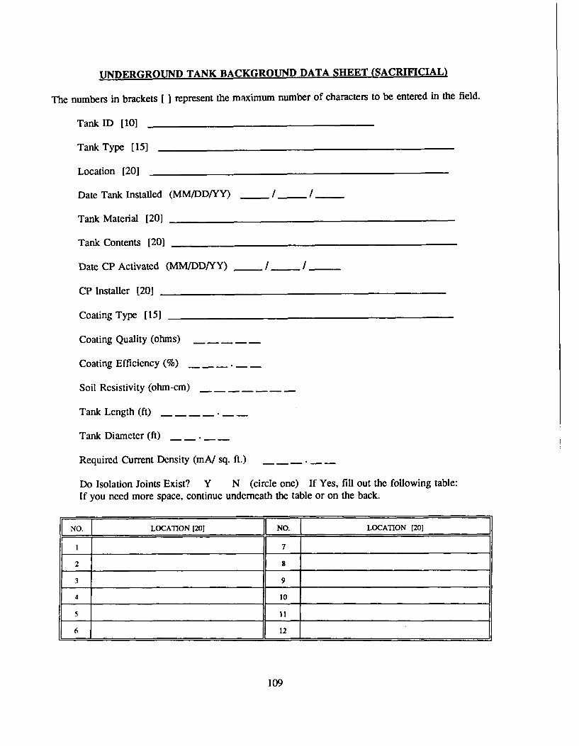
UNDERGROUND TANK BACKGROUND DATA SHEET (SACRIFICIAL)
The numbers in brackets [] represent the maximum number of characters to be entered in the field.
Tank ID [10]
Tank Type [15]
Location [20]
Date Tank Installed (MM/DD/YY) / /
Tank Material [20]
Tank Contents 120]
Date CP Activated (MM/DD/YY) I / ___
CP Installer [201
Coating Type [15]
Coating Quality (ohms)
Coating Efficiency (%)
Soil Rcsistivity (ohm-cm)
Tank Lcngth (ft)
Tank Diameter (ft)
Required Current Density (mA/ sq. ft.)
Do Isolation Joints Exist? Y N (circle one) If Yes, fill out the following table:
If you need more space, continue underneath the table or on the back.
NO._ LOCATION [201 NO. ( LOCATION [201
1 7
2 8
3 9
4 10
5 II
6 12
109

TEST SITE BACKGROUND DATA SHEET
The numbers in brackets [ ] represent the maximum number of characters to be entered in the field.
Part I: Test Site Information and Initial Potentials
Pipe ID [10] Section ID [4]
OR Tank ID [10]
Test Site ID [8]
Location [30]
Description [2J]
Vendor [30]
Surface or Flush Mounted? S F Tools Required [20]Natural Potential (V) Intf. Bond Resistance (ohms)
Does interference exist? Y N Shunt Resistor Value (ohms)
Number of Wires (should be the same as the number of entries in the Initial Potentials table below)
Comment 1 [30]Comment 2 [301
POTENTIALS (VOLTS)
NO. IDENTIFIER FUNCTION CONNECTED * DISCONNECTED * DIELECTRIC
*Enter initial potcntials in the left half of each block. These are potentials that were measured at CPsystem installation. Enter today's potentials in the rigzht half of each block.
110

TEST SITE BACKGROUND DATA SHEET (cont'd)
Part II: Anode Bed Data and Initial Anode Current OutDuts
Test Site ID [8]
Anode Type [20]
Anode Material [20]
Anode Diameter (inches) Anode Length (inches)
Anode Weight (lbs.)
Number of: Anodes Anode Currcnt Output Terminals _
(should be the same as the number ofentries in the Anode Current table below)
Design Life (yrs.) Anode Spacing (ft.)
Structure to Anode: Distance (ft.) Direction [20]Cable Gauge Cable Insulation Type [10]
ANODE CURRENT OUTPUTS (AMPS)
If you need more space, continue underneath the table or on the back. initial anode currents are those thatwere measured when the CP system was installed.
TERMINAL INITIAL ANODE TODAY'S ANODE TERMINAL INITIAL ANODE TODAY'S ANODENUMBER CURRENT (A) CURRENT (A) NUMBER CURRENT (A) CURRENT (A)
1 8
2 9
3 10
4 11
5 12
6 13
7 14
Ill

TEST SITE BACKGROUND DATA SHEET (cont'd)
Part II: Anode Bed Data and Initial Anode Current Outputs
Test Site ID [81
Anode Type [201
Anode Material [20]
Anode Diameter (inches) . . . . . Anode Length (inches)
Anode Weight (lbs.)
Number of: Anodes Anode Current Output Terminals(should be the same as the number ofentries in the Anode Current table below)
Design Life (yrs.) Anode Spacing (ft.)
Structure to Anode: Distance (ft.) ----- Direction [20]
Cable Gauge Cable Insulation Type [10]
ANODE CURRENT OUTPUTS (AMPS)
If you need more space, continue underneath the table or on the back. Initial anode currents are those thatwere measured when the CP system was installed.
TERMINAL INITIAL ANODE TODAY'S ANODE TERMINAL INITIAL ANODE TODAY'S ANODENUMBER CURRENT (A) CURRENT (A) NUMBER CURRENT (A) CURRENT (A)
1 8
2 9
3 10
4 11
5 12
6 13
7 14
Ill

-0-
_m 00i. a. I
0
w ~ O 0-C !
w cr.01 z 0
1 co 0 x
0Dzz 03wo . crW
zW4 ZW)! 0.w.ZL ow wwcui 0U
U-1.I I- izU;co- z w >-
- 0 Z 0
w : -cc= wI. <00 w 0
0
> O z
<
c. 0 z
->zu
113 - L

us- I. Z- 0 WOZ
00
I.-r _Lu *w 1U 0< W t c 9Lui -CI.- -
0 a 01- 0 ;woo 0 -
WUJOW
<LL ZLCC-
- /) us~'~W)
Lu~~ m~ Lw0 LO oz ~ - Lu
0 w -. z 0z I-Ul0Ul 1 0 x 0 03: 2 0 < IL :UAam 0-pm- nz~~~~~L XZ cc ( v -
I-- CE.Cz O_j 0 c - LL W l CCLU0-j '-UW J
LL LU U4
<I U-Q '- 0w
0 L
114 ~t

x -xz - 0 0.a
wz x co -j m
00 IL 41.w m0 co
LL .C .> -
mo c z i-0 r. 0
o a 0 IL
> wU wLUI
LLC I- W 0. . I.oJ4 oz ILLz z c XW3: z WLL
o CI> -- <- 0 M
LL LU mUc
-U ClI- z IL 0&IL g
ae, o~ 0 0z3
I- w~
co I0 -
C0 .. w
z o
o z115

w 0
0 UW
- = L
0 003.
to 4. 0 C
5 W J 10 cr 0JWWWO 1.,no: .
0_ zi w- n a1 crZO
Con o
z E)i0 0_0_
<LL
C)0 -
a . 0 ,3cocr C
oz
cc z L z i-
r- . -
0 Z 2 O co LU CCo I-- w
.- Z
116wZ

z
0 1
0 0
0~Z0
<1 W zc
co* 0 L)
00
z zODo-
Co '-00"'
0 au
4c 000U
< w 0- ccw<
a.~~ w - LCUoc uz L ' W I-c C2W
Ui Ww 0m(00
117

APPENDIX D: Sample Implementation Specification for Impressed Current CP Diagnostic
OVERVIEW
This Appendix contains an example of a scope of work which may be used by an Army installationwishing to utilize a contractor for the implementation of Impressed Current CP Diagnostic. Words thatare in [bold print and brackets] indicate site specific data to be inserted by the installation. ThisAppendix is only intended to be a guide for the technical content of the scope of work. Each installationmay wish to add, change, or delete sections or use a different format depending upon its typicalcontracting procedures.
Maps are referred to throughout the specification. These maps are to be supplied by each
installation as an attachment and are not included in this publication.
The remainder of Appendix D contains the complete sample implementation specification.
SPECIAL NOTE: The Army Technical Manual referred to in Paragraph 1.1.4 of the specificationwas in publication and had not been released at the time that this manual was written. Until it is released,references to it should be deleted from this specification. Such references will appear in {brackets).When it is released, insert the number in place of the question marks given in each bracketed reference.
118

SCOPE OF WORK
IMPLEMENTATION OF IMPRESSED CURRENT CP DIAGNOSTICAT
[INSTALLATION'S NAME]
1.0 GENERAL
1.1 APPLICABLE PUBLICATIONS
The publications listed below form a part of this specification to the extent referenced. Thepublications are referred to in the text by basic designation only.
1.1.1 U.S. Army Construction Engineering Research Laboratory (USACERL)
USACERL ADP Cathodic Protection DiagnosticReport M-91/24 Computer Program for Sacrificial
and Impressed Current Systems:Overview and User's Manual
1.1.2 Headquarters, Department of the Air Force
Air Force Manual Maintenance and Operation ofAFM 85-5 Cathodic Protection Systems9 February 1982
1.1.3 National Association of Corrosion Engineers
NACE Standard Recommended Practice,RP-01-69 Control of External CorrosionJanuary 1983 revision on Underground or Submerged
Metallic Piping Systems
NACE Standard Recommended Practice,RP-02-85 Control of External CorrosionMarch 1985 on Metallic Buried, Partially
Buried, or Submerged LiquidStorage Systems
{1.1.4 Headquarters, Department of the Army)
(Technical Manual (Operation and MaintenanceTM 5-??? of Cathodic Protection(This document had not Systems)yet been released when thismanual was published))
119

1.2 SYNOPSIS OF WORK
The Contractor shall furnish all materials and perform all services required to implement the
Impressed Current Cathodic Protection (CP) Diagnostic computer program as set forth in these detailedspecifications for [installation's name]. Approximately [insert number] linear feet of underground
piping, [insert number] underground storage tanks, and [insert number] water storage tanks are to beincluded. These structures are shown on the maps in Appendix III of this specification. CP Diagnosticmaintains background information and field test data about cathodic protection systems and the structuresthat they protect and generates reports that assist in pinpointing system malfunctions. Work shall beaccomplished in accordance with the publications cited in section 1.1, except as modified elsewher, ;ithese specifications. The following items of work, explained more fully in Sections 2.0 through 6.0, areic!Luded:
1.2.1 Inventory and Initial Field Testing: Establish an identification system for the specifiedrecti iers, junction boxes, underground pipes, underground storage tanks, water storage tanks, and test sitesas directed in the CP Diagnostic User Manual. Furnish reproducible mylar maps showing the rectifiers,junction boxes, pipe network, tanks, and test sites with all of the identification numbers clearly marked.Collect and record all of the required background data for each rectifier, junction box, anode bed,structure, and test site, initial structure-to-soil potentials, initial anode current outputs, and dielectricconditions as explained under Section 2.0, Inventory.
1.2.2 Data Entry: Enter all data into the CP Diagnostic program and provide a complete database'ind an error-free run.
1.2.3 Generation of Reports: Furnish computer printouts of the reports specified in Section 4.0.These rcporls show the information input into the data base and pinpoint possible problems in the cathodic
rllotection svstcm. Include these the final report, along with a discussion of the results. ProviderCcoiincildalions where applicable.
1.2.4 Training: Provide training to DEll personnel on the CP Diagnostic system set-up and use.
1.2.5 Preparation of Final Report: A final report as discussed in Section 6.0 shall be prepared witha formal narrative section describing the work and method of accomplishment. All data and program-generated reports shall also be included. The final report shall be presented to the DEH at an exit briefing.
13 PROJE-CT MANAGEMENT
1.3. 1 Proiect Supervisor: The supervisor shall serve as a single point of contact and liaison for allwork rcquired under this Contract. Upon award of the Contract, this individual and an alternate shall befilmediately designated in writing by the Contractor. These designated individuals shall be approved bythe Government Project Engineer. One of these individuals shall be available at the installation wheneverthe Contractor is performing work under this Contract.
1.3.2 Installation Assislance: A duly authorized representative from within the Directorate of't-iiricring dnd Housing will serve as the point of contact for obtaining available information and
,s.sisling in establishing contacts with the proper individuals and organizations, as necessary, in theaccomplishment of tile work required under this Contract.
120

1.3.3 Public Disclosures: The Contractor shall make no public announcements or disclosuresrelative to information contained or developed in this Contract, except as authorized by the ContractingOffice.
1.3.4 Conferences: Conferences shall be scheduled as shown on the Implementation Schedule basedon work status or whenever requested by the Contractor or Government Project Engineer for the resolutionof questions or problems encountered in the performance of the work. The Contractor shall be requiredto attend and participate in all conferences pertinent to the work as directed by the Contracting Officer.
1.3.5 Qualifications of Personnel: Field inspections shall be performed by technically :rainedpersonnel under the direct supervision of a National Association of Corrosion Engineers (NACE)-accredited Cathodic Protection Specialist OR a NACE-accredited Corrosion Specialist with a specialty areaof Cathodic Protection. All data and the final report shall be, at a minimum, reviewed and signed by aNACE-accredited Cathodic Protection Specialist OR NACE-accredited Corrosion Specialist with aspecialty area of Cathodic Protection.
1.3.6 Scheduling: At the beginning of the contract period, the Contractor shall submit animplementation schedule using the format shown in Appendix II of this specification for approval by theGovernment Project Engineer. Detailed schedules for field work will be coordinated through theGovernment Project Engineer each week. In-progress reviews should be scheduled as follows:
At the completion of establishing the rectifier, junction box, structure and test site identifica-tion in the office and prior to proceeding with any field work.
* At the completion of the field survey data input.* At the final exit briefing during the presentation to the DEH of the complete CP Diagnostic
system.
Incremental Contractor checked data shall be furnished to the government as required by the GovernmentProject Engineer for review and concurrence.
1.4 PAYMENT
1.4.1 Overhead, Supervision, Site Visits and Inspection: All overhead, supervision, travel costs,and other expenses to be incurred by the Contractor, directly or indirectly, including costs of the site visitsthroughout the work, shall be included in the proposal under the work items described. These costs shallnot be considered separately.
1.4.2 Monthly Payment, Less Deductions: The Contractor shall be paid, upon the submission ofproper invoices or vouchers, the prices stipulated in the proposed schedule rendered and accepted, lessdeductions, if any, as herein provided. Unless otherwise specified, payment will tbe on performanceaccepted by the U.S. Government when the amount due on such performance so warrants. Payment maybe requested not more than once each month.
1.4.3 10 Percent Retention: In making such payments, the U.S. Government may, at its option,retain I0 percent of the estimated amount until final completion and acceptance of the Contract work.lowever, if the U.S. Government, at any time after 50 percent of the work has been completed, finds that
satisfactory work is being performed, it may authorize any of the remaining payments to be made in full.When the work is substantially complete, if the Government considers the amount to be retained in excess
121

excess of the amount adequate for the protection of the U.S. Government, the Government may, at itsdiscretion, release to the Contractor all or a portion of such excess amount.
1.4.4 Final Payment on Release: Upon completion and acceptance of all work, the amount due theContractor under this Contract is dependent upon the presentation of a properly executed voucher afterthe Contractor has furnished the U.S. Government with a release, if required, of all claims against the U.S.Government arising by virtue of this Contract, other than claims in stated amounts as may be specificallyexpected by the Contractor from the operation of the release. If the Contractor's claim to amounts payableunder this Contract has been assigned under the Assignment of Claims Act of 1940, as amended (31U.S.C. 203, 41 U.S.C. 15), a release may also be required of the assignee.
1.5 SAFETY
The Contractor shall conduct operations in a safe manner at all times. Safety provisions shall beconsistent with the Army Corps of Engineers Safety Manual. The Contractor's operation shall not causea potential safety hazard to occupants of the area, Contractor's and U.S. Government personnel, and U.S.Government property.
1.6 CONTRACTOR & INSTALLATION WORK HOURS
The normal hours of operation at the installation will be between [insert hours] Monday throughFriday except on the following Federal holidays:
New Years Day President's DayMemorial Day 4th of JulyLabor Day Veterans DayThanksgiving ChristmasMartin Luther King Day Columbus Day.
Field work in Family Housing areas shall be conducted during the hours of [insert hours]. Other siteconditions or security requirements may necessitate that the required field work be performed outside ofthe normal hours of operation.
1.7 ACCESS TO RESTRICTED AREAS
The list of structures and test sites which are in restricted areas, and the procedure to obtain accessto these areas is as follows: [insert list of structures/ test sites and access procedures]
1.8 CONTRACT DURATION
The Contract completion date shall be [insert number] calendar days after the Notice to Proceedhas been received by the Contractor.
1.9 POINTS OF CONTACT
1.9.1 Directorate of Engincering and Housing Point of Contact: [list name(s) here]
[INSERT OTHER ORGANIZATIONS AND POINTSOF CONTACT HERE AS APPLICABLE]
122

2.0 INVENTORY AND INITIAL FIELD TESTING
2.1 GENERAL
A complete description of the inventory and field test data requirements for CP Diagnostic is givenin the USACERL report "Cathodic Protection Diagnostic Computer Program for Sacrificial and ImpressedCurrent Systems: Overview and User's Manual." This publication will be referred to as the CP Diag-nostic User's Manual throughout the remainder of this specification. The Contractor shall use installationdrawings and records, perform field surveys, conduct interviews with DEH personnel, and assemble otherinformation as necessary to gather the required data. The Contractor shall make a reasonable efi'ort toobtain 100 percent of the required data. If any part of the required data cannot be collected, ,heContractor shall submit in writing a complete list of the unavailable data, along with a reason for itsunavailability. The reason must be approved by the Contracting Officer before the database will beaccepted as "error-free" as discussed in Section 3.0. A complete listing and explanation of unavailabledata shall also be given in the final report. The Contractor shall copy blank forms from the CP DiagnosticUser's Manual or other reference as necessary to perform work and submit with the final report asspecified by this Contract.
2.2 IDENTIFICATION OF RECTIFIERS
The Contractor shall define and set up an identification system for all of the rectifiers for which CPDiagnostic is to be implemented as described in the CP Diagnostic User's Manual. This shall be donein coordination with and shall be subject to approval by the DEH point of contact given in section 1.9.Each rectifier shall be assigned its own unique identification number. The rectifiers shall be clearlyidentified on the reproducible maps described in 1.2.1.
2.3 COLLECTION OF RECTIFIER BACKGROUND DATA
The Contractor shall collect a complete set of background data as described in the CP DiagnosticUser's Manual for each rectifier identified under paragraph 2.2. This information shall be collected onthe Rectifier Background Data Sheet provided in the CP Diagnostic User's Manual or a reasonablefacsimile thereof. One form shall be completed for each rectifier. The following information is requiredfor each rectifier:
" Location • Number of fuses" Rectifier type • Fuse rating" Rectifier manufacturer • Number of circuits• Rectifier model * Operating mode" DC rated voltage * Initial rheostat setting" DC rated current • Initial automatic (set point)." Reference electrode
potential
For each circuit of the rectifier, the following information is required:
" Shunt value • DC voltage* Tap setting: fine • DC current" Tap setting: coarse • AC voltage• Circuit resistance - AC current.
123
If initial rectifier readings (i.e., those taken when the CP system was installed) are available, they
shall also be recorded on the data sheets.
2.4 IDENTIFICATION OF JUNCTION BOXES AND ANODE GROUND BEDS
The Contractor shall define and set up an identification system for all junction boxes associated withall of the rectifiers identified in paragraph 2.2 which protect underground structures. This shall be doneas described in the CP Diagnostic User's Manual. This shall be done in coordination with and shall besubject to approval by the DEH point of contact given in section 1.9. Each junction box (with itsassociated ground bed) shall be assigned an identification number. The junction boxes shall be cle-.-;yidentified on the reproducible maps described in 1.2.1.
2.5 COLLECTION OF JUNCTION BOX AND ANODE GROUND BED BACKGROUND DATA
The Contractor shall collect a complete set of background data for each junction box identified inparagraph 2.4 with its associated anode ground bed as described in the CP Diagnostic User's Manual.This information shall be collected on the Ground Bed Background Data Sheet provided in the CPDiagnostic User's Manual or a reasonable facsimile thereof. One form shall be completed for eachjunction box/ ground bed. The following information is required for each junction box/ anode ground bed:
" Anode type * Number of anode current output terminals" Anode material • Anode spacing" Anode diameter * Structure-to-anode distance" Anode length e Structure-to-anode direction" Anode weight • Cable gauge• Design life • Cable insulation type" Maximum current • Shunt ratings
density • Ground bed description." Number of anodes
2.6 COLLECTION OF ANODE CURRENT OUTPUTS
For each anode current output terminal of each junction box identified in 2.4, the Contractor shallmeasure the anode current output in amperes. The measurements shall be recorded on the Ground BedBackground Data Sheets that were prepared under paragraph 2.5. if initial currents (those that were takenwhen the CP system was installed) are available, they shall also be recorded on the data sheets. Currentsshall be measured using the procedures in AFM 85-5 (and/or Army TM 5-???).
2.7 COLLECTION OF WATER STORAGE TANK ANODE BACKGROUND DATA
For each of the rectifiers identified in Paragraph 2.2 that protects a water storage tank, the Contractorshall collect a complete set of background information concerning the anodes in the water tank asdescribed in the CP Diagnostic User's Manual. This information shall be collected on the Water TankAnode Background Data Sheet provided in the CP Diagnostic User's Manual or a reasonable facsimilethereof. One form shall be completed for each rectifier that protects a water storage tank. The followinginformation is required for each rectifier with its associated anodes:
" Anode type • Number of anodes per wall/bowl string" Anode material • Wall/bowl anode spacing
124

• Anode manufacturer • Number of anodes on riser string" Design life • Riser string length" Cable gauge - Riser anode spacing* Cable insulation type • Anode-to-wall distance• Is it an ice-free design? * Number and location of reference electrodes• Number of wall/bowl - Wall/bowl anode string
anode strings length.
2.8 DEFINITION AND IDENTIFICATION OF PROTECTED STRUCTURES
The Contractor shall define and set up an identification system for the network of protectedstructures as described in the CP Diagnostic User Manual. This shall be done in coordination with andshall be subject to approval by the DEH point of contact given in section 1.9. For an underground pipingsystem, this procedure involves dividing the system up into a series of pipe sections, each with its ownunique identification number. For a system of underground storage tanks and/or water storage tanks, eachtank will be assigned its own unique identification number. Each structure shall be given a unique ID andshall be clearly identified on the reproducible maps described in 1.2.1.
2.9 COLLECTION OF STRUCTURE BACKGROUND DATA
The Contractor shall collect a complete set of background data as described in the CP DiagnosticUser's Manual for each structure (i.e., pipe section or tank) identified under paragraph 2.2. Thisinformation shall be collected on the Pipe Section Background Data Sheet the Underground TankBackground Data Sheet, and/or the Water Tank Background Data Sheet provided in the CP DiagnosticUser's Manual or a reasonable facsimile thereof. One form shall be completed for each structure. It isthe Contractor's responsibility to reproduce the forms in sufficient quantities to collect data for the entiresystem. The following information is required for each pipe section:
" Location from - Coating quality (ohms)" Location to • Coating efficiency (%)" Date installed • Soil resistivity (ohm-cm)" Date CP activated - Section length (ft)" CP installer - Section diameter (in)" Coating type - Required current density (ma/sq ft).* Locations of isolation
joints
The following information is required for each underground storage tank:
• Tank type • Coating type" Location - Coating quality (ohms)• Date tank installed • Coating efficiency (%)" Tank material • Soil resistivity (ohm-cm)" Tank contents • Tank length (ft)" Date CP activated - Tank diameter (ft)" CP installer * Required current density (ma/sq ft)." Locations of isolation
joints
125

The following information is required for each water storage tank:
" Tank type • Bowl height• Location • Bowl width" Constructed by • Bowl geometry" Construction date • Riser height* Tank material • Water conductivity" Tank contents • Internal coating quality• Exterior coating - Internal coating efficiency" Interior coating * Required current density• Date CP activated - Total submerged area• Tank capacity - Location of isolation joints.
2.10 IDENTIFICATION AND DEFINITION OF TEST SITES
Each protected structure may have associated with it a series of "test sites." A "test site" may eitherbe a test station or any other test point at which potential measurements are taken, such as a riser or avalve. The Contractor shall define and set up an identification system for test sites and shall assign anID to each test site associated with each structure that was identified in paragraph 2.8. This shall be doneas described in the CP Diagnostic User's Manual. This shall be done in coordination with and shall besubject to approval by the DEH point of contact given in paragraph 1.9.
2.11 COLLECTION OF TEST SITE BACKGROUND DATA
The Contractor shall collect a complete set of background data as described in the CP DiagnosticUser's Manual for each test site identified under paragraph 2.10. This information shall be collected onthe Test Site Background Data Sheet provided in the CP Diagnostic User's Manual or a reasonablefacsimile thereof. One form shall be completed for each test site. It is the Contractor's responsibility toreproduce the forms in sufficient quantities to collect data for the entire system. The followingbackground information is required for each test site:
• Structure ID • Natural potential (volts)• Location - Interference bond resistance (ohms)• Description * Does interference exist?" Vendor • Shunt resistor value (ohms)" Surface or flush mounted • Number of wires• Tools required • Comments.
2.12 COLLECTION OF TEST SITE POTENTIAL MEASUREMENTS
For each potential measurement point of each test site identified in 2.10, the Contractor shall assignan identifier (such as wire color) and shall collect the following information:
" Measurement point identifier" Funiction of measurement point• On potential (volts)• "Instant-off" and/or off potential as required for evaluation of the system against the cathodic
protection criteria se'.-cted under section 4.3
126

If initial potentials (those that were taken when the CP system was installed) are available, they shall also
be recorded on the data sheets.
Potentials shall be measured using the procedures in AFM 85-5 {and/or Army TM 5-???). All of the
collected information shall be recorded on the Test Site Background Data Sheets that were prepared under
paragraph 2.11.
2.13 COLLECTION OF INITIAL DIELECTRIC CONDITION DATA
The Contractor shall determine the condition (i.e., good, shorted, etc.) of each dielectric fittng andshall record this information.
3.0 DATA ENTRY
3.1 GENERAL
The Contractor shall code for entry into CP Diagnostic all verified data collected from installationdrawings and records, field surveys, interviews, or other sources. Coding for the computer shall be inaccordance with the CP Diagnostic User's Manual. The result shall be a complete, error-free database.
3.2 DATA ENTRY
The Contractor shall enter data into the database on a Government-owned microcomputer. TheGovernment shall provide a copy of the CP Diagnostic program for the Contractor's use. The Contractorshall ensure and verify that the data stored in the database corresponds with the field data. Care shall betaken to ensure that data input into the database follows a sequence that avoids duplication or omissionsand provides as a finished product an error free, complete database ready for CP Diagnostic operations.
3.3 INITIAL DATA CHECKING
The rectifier, junction box/ ground bed, structure, and test site identification information shall beentered, checked, corrected by the Contractor, and approved by the Government's ContractingRepresentative prior to other data being input into the program. This information must correspond to thereproducible drawings covered in Paragraph 1.2.1.
3.4 DATA CHECKING
When the rectifier, junction box, anode/ ground bed, structure, and test site information is approvedand the remainder of the data has been entered, checked, and corrected by the Contractor, the Contractorshall produce one copy of the data stored in the computer for review by the Government. Any inputerrors discovered through the review of this "data dump" will be changed by the Contractor within a 2-week period after the review.
3.5 FINAL DATA CHECKING
If 5 percent or more of the data requires changes, a second "data dump" and review will be required.The Contractor will respond to changes of the second data dump within a 1-week period. Review andcorrection will continue in this same fashion until the data base is error free.
127

4.0 GENERATION AND INTERPRETATION OF REPORTS
4.1 STRUCTURE MASTER LISTING
The Contractor shall generate a complete Structure Master Listing report for the entire final (error-free) CP Diagnostic database for [installation's name]. This report displays background information foreach structure in the database and shall be submitted as part of the final report.
4.2 STRUCTURE LISTING
The Contractor shall generate a complete Structure Listing report for the entire final (error-free) CUDiagnostic database for [installation's name]. This report gives a concise listing (ID and location) forall of the structures in the database and shall be submitted as part of the final report.
4.3 TROUBLE READINGS REPORT
The Contractor shall generate a complete Trouble Readings report for the entire final (error-free)CP Diagnostic database for [installation's name]. This report identifies all test sites at which themeasurements do not meet the selected criteria of cathodic protection. Selection of the criteria to be usedshall be made in conjunction with the DEH and a NACE-certified Corrosion Specialist. Based upon theresults of the Trouble Readings report, the contractor shall identify locations in the system where problemsexist and further investigation is warranted. This shall be documented in the final report. Guidance forthe selection of criteria and the interpretation of data can be found in AFM 85-5, [Army TM 5-???,)NACE RP-01-69, and NACE RP-02-85.
4.4 RECTIFIER MASTER LISTING REPORT
The Contractor shall generate a complete Rectifier Master Listing report for the entire final (error-free) CP Diagnostic database for [installation's name]. This report prints the background informationfor each rectifier recorded in the database and shall be submitted with the final report.
5.0 TRAINING
5.1 CLASSROOM INSTRUCTION
The Contractor will provide a minimum of [insert number] hours of training in the use of the CPDiagnostic System to employees of the DEH during the Contract. This orientation and training willinclude, but is not to limited to, the following:
* Computer and program startup* Definition of rectifiers, junction boxes, structures and test sites* Field data collection (i.e., structure-to-soil potentials, anode current outputs,
rectifier readings, and dielectric conditions)* Data entry and editing* Report generation* Interpretation of reports* Use of the reports to identify problems with the CP system* Backing up the data base* Exiting the program
128

5.2 SCHEDULING
A training schedule will be coordinated with and submitted to the DEH for approval a minimum of
15 working days prior to the training. The Contractor will contact the DEH representative directly to
reserve conference rooms and training areas and to check the availability of audio/visual equipment,
computer terminals, and other equipment or facilities necessary for the training. Equipment (e.g., audio/
visual equipment, computer terminals, etc.) that is necessary for the training but is not available from theDEH shall be furnished by the Contractor.
5.3 LIST OF ATTENDEES
The Contractor shall include, in the final report, a list of DEH personnel including name, title, officesymbol, and telephone number that were trained under this contract.
6.0 FINAL REPORT
6.1 REPORT FORMAT
Formal reports and tabular data shall be typed or computer-printed (at least near letter quality) on8-1/2 x Il-in. bond paper with foldouts for maps, sketches, schematics, charts, graphs and other illustrativematerial, as may be necessary. Data which cannot be clearly described in narrative form shall be showngraphically.
6.2 REPORT BINDING
Formal documents shall be securely bound with a durable cover. The title of the document shallappear on the cover of all submittal documents. Final documents shall be bound in a manner which willfacilitate repeated disassembly and reassembly, unless otherwise specified herein.
6.3 NETWORK DRAWINGS
Site maps showing the locations of the protected structures, rectifiers, junction boxes, and the testsites shall be reproducible mylar drawings. The drawings shall provide easy identification of the pipesections, tanks, and test sites.
6.4 REPORT SUBMITTAL
[Insert number] preliminary (draft) copies of the final report shall be submitted to the Governmentfor approval. Following the return of comments, the Contracting Officer will schedule a meeting for theirdiscussion if necessary. The Contractor shall furnish written notification of intended action on eachcomment within I week after this meeting. Intention of noncompliance with any comment shall besubstantiated in detail. Authorization to proceed with final submittal will be granted in writing with orafter the Contracting Officer's approval of the contractor's intended actions on the review comments.[Insert number] copies of the final report will be submitted.
129

6.5 ORGANIZATION OF REPORT
Narrative contents shall be arranged in a logical sequence and organized by sections. Reproducibletransparencies, drawings, and/or maps shall be submitted separately. The report shall fully document theimplementation process, the data collected, and the results achieved. The report shall include, but is notlimited to, the following items:
6.5.1 A formal narrative section describing the work that was done, how it was accomplished, andwhen it was accomplished. The narrative shall include a brief description of each of the followingportions of this report.
6.5.2 The CP Diagnostic reports specified in Section 4 shall be generated from the completed database and submitted as part of the final report.
6.5.3 Based upon the results of the above reports, the contractor shall note areas of the system inwhich further investigation is warranted to pinpoint problems in the CP system. The contractor shall makerecommendations as to the nature, extent, and approximate "ballpark" cost of these investigations.
6.5.4 A list of DEH personnel including name, title, office symbol, and telephone number that weretrained by the Contractor under the Contract.
6.5.5 An Appendix containing copies of all of the data collection forms that were completed underSection 2, Inventory. These shall be arranged in an organized, logical sequence.
6.5.6 All maps and drawings necessary to identify the CP system and protected structures, includingtwo copies of the mylar maps.
6.5.7 A backup copy of the complete, error-free CP Diagnostic database on 5-1/4 in. floppy disks.
6.6 EXIT BRIEFING
Upon completion of the work, an exit briefing will be given to the DEH. The final report shall bepresented to the DEH at this briefing. The briefing shall cover the scope of work, accomplishments,findings, problems, conclusions, and identification of problem areas in the CP system.
130

CONTRACT SPECIFICATION APPENDIX I
LIST OF GOVERNMENT FURNISHED MATERIALS AND INFORMATION
The Government shall furnish the following items at the time the Notice to Proceed is issued,
however, all will be returned to the Government at the end of the project:
• Area site plan maps (1 set)
" Supplemental area maps (I set)
" Drawings of the cathodically protected structures (I set)
" Drawings or other description of the cathodic protection system. If drawings showing thecathodic protection system do not exist, other descriptive material shall be provided as available.
" Other existing background or historical information (as available) that cannot be readilymeasured in the field by the Contractor and is required under Section 2.0, Inventory.
" CP Diagnostic computer program
" USACERL ADP Report "Cathodic Protection Diagnostic Computer Program forSacrificial and Impressed Current Systems: Overview and User's Manual"
131

CONTRACT SPECIFICATION APPENDIX II
IMPLEMENTATION SCHEDULE
ITEM NUMBER
1. Mylar Maps
2. Structure andSystem Identi-fication
3. Background andField DataCollection
4. Data Entry
5. Report Generationand Interpretation
6. Training
7. Final Report andBriefing
0 20 40 60 80 100 120 140 160 180 200Calendar Days from Contractor's Notice to Proceed
[INSTALLATION MAPS SHOULD BE ATTACHED AS APPENDIX MI. ANY OTHERATTACHMENTS SUCH AS PRICE/COST SCHEDULES SHOULD BE INCLUDED INADDITIONAL APPENDICES]
132

APPENDIX E: Relationships Between System Components
133

U)< wcoOcc
00
woLi- w 0O
WZ 0 -<. w -
fJ Dcr
w 0
<00
LU0 0w :3 _OCCE
"17 Z134

I-
z LU -LUcom
zu W o ow m
zc 0M
0-JL-U) 0 W
cr. I.- a
0 W z 1.0
=) a.135

APPENDIX F: Background Data Collection Forms for Impressed Current CP Diagnostic
136

RECTIFIER BACKGROUND DATA SHEET (IMPRESSED CURRENT)
Rectifier ID 1101 _________________________
Rectifier Location [20] _____________________________
Rectifier Type 1101]__________ Rectifier Manufacturer [10] ________
Rectifier Model [10] ) __________
DC Rated Voltage (V) -- .___DC Rated Current (A)
Reference Electrode Potential (V)-
Number of Fuses -___ Fuse Rating (A)
Number of Circuits___
Operating Mode_________________________
Initial Rheostat Setting
Initial Automatic (set point)
Enter the settings for each circuit in the following table. Enter -initial settings in the left half of eachblock. These are the settings that were measured at CP system installation. Enter today's settings in therig!ht half of each block.
Parameter Circuit J Circuit 1 Circuit
Shunt Value (ohms) I_________Tap Setting: Fine
Tap Setting: Coarse
Circuit Resistance (ohms)
DC Voltage (V) __________________
DC Current (A)
AC Volage (V)
AC urrnt(A)
137

GROUND BED BACKGROUND DATA SHEET (IMPRESSED CURRENT)
The numbers in brackets [ ] represent the maximum number of characters to be entered in the field.
Rectifier ID [10] Junction Box ID [5]
Anode Type [20]
Anode Material [20]
Anode Diameter (in) Anode Length (in) Anode Weight (Ib)
Design Life (yr) Max. Current Density (mA/sq.ft.)
Number of: Anodes Anode Current Output Terminals
Anode Spacing (ft) - -
Structure to Anode: Distance (ft) Direction [20]Cable Gauge -- __ Cable Insulation Type [10]
Shunt Rating: Main Circuit Amps per mV
Anode Circuit __ Amps per mV
Ground Bed Description [60]
ANODE CURRENT OUTPUTS (AMPS)
Initial anode currents refer to currents that were measured when the CP system was installed.
TERMINAL INITIAL TODAY'S TERMINAL INITIAL TODAY'S
NUMBER ANODE ANODE NUMBER ANODE ANODECURRENT (A) CURRENT (A) CURRENT (A) CURRENT (A)
8
2 9
3 10
4 1
5 12
6 13
7 14
138

WATER TANK ANODE BACKGROUND DATA SHEET (IMPRESSED CURRENT)
The numbers in brackets [ represent the maximum number of characters to be entered in the field.
Rectifier ID [101
Anode Type [20]
Anode Material [20]
Anode Manufacturer [20]
Design Life (yrs)
Cable Gauge Cable Insulation Type [10]
is this an ice-free design? Yes No (circle one)
Wall/ Bowl Anode Strings:
No. of Wall/ Bowl Anode Strings No. Anodes per String
String Length (ft) Anode Spacing (ft)
Riser Anode String:
No. of Anodes on Riser String Riser String Length (ft) -
Anode Spacing (ft)
Anode-to-Wall Distance (ft)
Reference Electrodes:
No. in Riser: Location [20]
No. in Bowl: Location [201
139
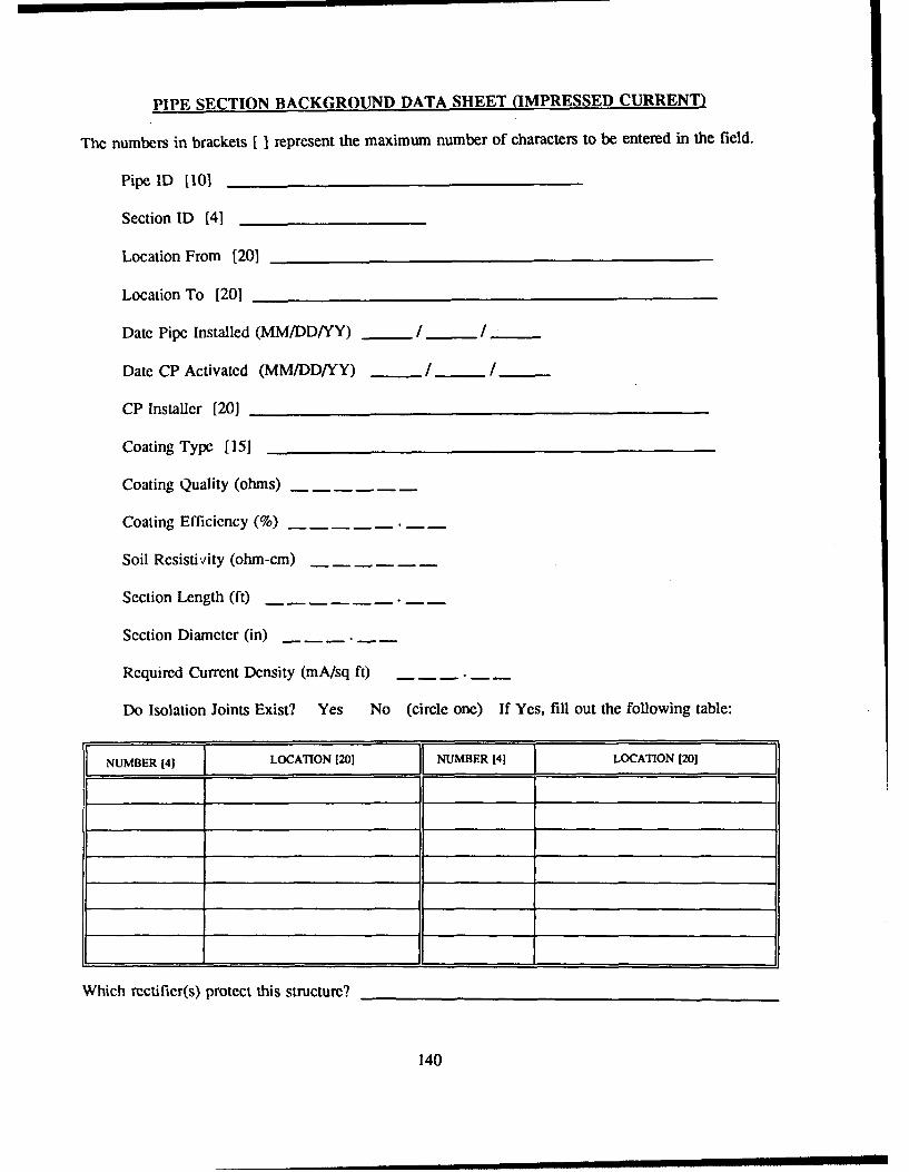
PIPE SECTION BACKGROUND DATA SHEET (IMPRESSED CURRENT)
The numbers in brackets [ represent the maximum number of characters to be entered in the field.
Pipe ID [101
Section ID [41
Location From [20)
Location To [201
Date Pipe Installed (MM/DD/YY) / / "
Date CP Activated (MM/DD/YY) _ / /
CP Installer [20]
Coating Type [15]
Coating Quality (ohms)
Coating Efficiency (%)
Soil Resistivity (ohm-cm)
Section Length (ft)
Section Diameter (in)
Required Current Density (mA/sq ft)
Do Isolation Joints Exist? Yes No (circle one) If Yes, fill out the following table:
NUMBER 41LLOCATION [201 IE NUMBER [41 LOCATION [201
Which rectifier(s) protect this structure?
140

UNDERGROUND TANK BACKGROUND DATA SHEET (IMPRESSED CURRENT)
The numbers in brackets IIIrepresent the maximum number of characters to be entered in the field.
Tank ID 1101 __ _ _ _ _ _ _ _ _ _ _ _ _ _ _ _
Tank Type [15] _________________________
Location [20] _____________________________
Date Tank Installed (MM/DD/YY)__I I
Tank Material [20] _________________ ________
Tank Contents [20] __________________________
Date CP Activated (MMJDD/YY) ___I /___
CP Installer [201 ___________________________
Coating Type 1151 ___________________ ________
Coating Quality (ohms)
Coating Efficiency (%)_
Soil Resistivity (ohm-cm)
Tank Length (ft)
Tank Diameter (in) ---
Required Current Density (mA/sq ft) --- --
Do Isolation Joints Exist? Yes No (circle one) If Yes, fill out the following table:
NUMBER [41 LOCATION 1201 NUMBER [41 ]LOCATION [20]
Which rectifier(s) protect this structure? ________ ____________________
141
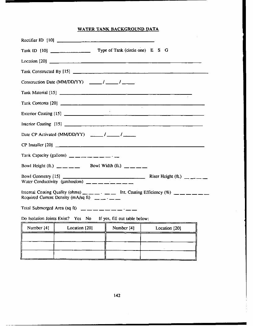
WATER TANK BACKGROUND DATA
Rectifier ID [10]
Tank ID 1101 Type of Tank (circle one) E S G
Location [201
Tank Constructed By [151
Construction Date (MM/DD/YY) / /
Tank Material [151
Tank Contents [201
Exterior Coating [15]
Interior Coating [151
Date CP Activated (MM/DD/YY) _ 1 _ 1__
CP Installer [20]
Tank Capacity (gallons)
Bowl Height (ft.) Bowl Width (ft.)
Bowl Geometry [15] Riser Height (ft.)Water Conductivity (plmhos/cm)
Internal Coating Quality (ohms) Int. Coating Efficiency (%)Required Current Density (mA/sq ft)
Total Submerged Area (sq ft)
Do Isolation Joints Exist? Yes No If yes, fill out table below:
Number [4] Location [201 L Number [4] Location [20]
142

TEST SITE BACKGROUND DATA SHEET
The numbers in brackets [ represent the maximum number of characters to be entered in the field.
Pipe ID [101 Section ID [4]OR Tank ID [10]
Test Site ID [8]
Location [30]
Description [20]
Vendor [30]
Surface or Flush Mounted? S F Tools Required [20]Natural Potential (V) Intf. Bond Resistance (ohms)
Does interference exist? Y N Shunt Resistor Value (ohms)
Number of Wires (should be the same as the number of entries in the Initial Potentials table below)
Comment 1 [301Comment 2 [30]
POTENTIALS (VOLTS)
NO. IDENTIFIER FUNCTION CONNECTED * DISCONNECTED * DIELECTRIC
'~Enter initial potentials in the left half of each block. These are potentials that were measured at CPsystem installation. Enter today's potentials in the right half of each block.
143

APPENDIX G: Diagram of Program Flow for Impressed Current CP Diagnostic
The following five pages labelled A through E depict the flow through the Impressed Current CPDiagnostic program. The following conventions and symbols are used:
• A rectangle denotes a point of decision. This includes menus, selection screens (such as selectinga pipe section or selecting a database), and other places where a decision is required before youcan proceed.
" A circle denotes any other data entry screen or option that does not involve a decision.
" A letter and number in brackets { I denotes a cross-reference to the main text of the manual.All menus and menu options are cross-referenced with the main text.
144

-0-
CC I a
0 0cz
L _ OD - 0
F- EWO~
I-~se CL W-l
0O Cl,,C
Z CO 0 3-
Dz z 0 c5
0 ' wE <w 0 0
0 L
-_U < 0C,,>
x C
0o Z
0... 0 Z
CC 0w wU 0<0
0C. m m-4 W.. . -a tuw LLm l
zu 0 w 0
LUzW
a.I Z
(u') 0
746
145

uz-S
-U. I.-
UJW 00Z.I.-
w L ,)w
0) usW W W.-C. w 2)
ul 2l Ix(! a ww L
Q_ Z~ w wa
-J-a 0U<l
WI-
0 W DJ. .jU5
l
PO n .. ,.
0l - L) M S
LL.~U -.. U
ow -a i
0 1-01- Z
w cO.--. W..c ou
Zw <' 0LLJ~~~~~~8 ccnI-a w# W u
0 - Z0 a u21-- 0 w
cc~~~S 0 L CQZZM I
Zj! CO usw az 0
*W 00O
Ozwin! Z'u
w .1-
a -J 0 1... m146I

I0
0 wi
-- S
Lut WOgg sO* -o
0)0 WW a -c
-r 0
C)0 0
o z
1z z .
I.- Sl
U -
£, OX -cm
* - 4-. .c wcc - -.
-U cc uo V ~ *
--11 --
'C ~0 0.usz w 3
0'-~ 35
C) .. *3m
cco- go U -0 a
I- -0 IL0 dc -
LU0 - wsO C
a . z ..MZw wm Wo .0' N . 4~
C l) zz 1 .U z ,-6 3
LU W4600 - *0 6.~oUu 0 -Cc
w a.3 0 ~
78& ! -. "I
147

.- Oo o Z
~I -
oz
5E - Luc
0 -
ZCi 3 ,0;.o ZCo 0 C UI
C, ixa
0o L
1. wo Co
00C) 0 1Cmz -I
c, woom 1 c cC0 0 C 0z ~
CeCozw 0z
00cc 0 Iwa
0zK)- C) OW00-148r

0~
wZ ccr1%
ZCOO
0~~~ z'Q O
< C0 COW
-mm
IW 0
CO J 0)Owl
z0.~W0
0 0 w zLLW
(UAW
a a 0U-COW 0
-CC -Ca 0
149c
DISTRIBUTION
Chief of Engineers Military Dist of WashingtonATTN: CEHEC-IM-LH (2) A'IN: DEHATTN: CEHEC-IM-LP (2) Cameron Station (3) 22314ATTN: CERD-L Fort Lesley J. McNair 20319
Fort Myer 22211CEHSC
ATTN: CEHSC-FUW 22060 TRADOC (19)HQ, TRADOC, ATTN: ATEN-DEH 23651
US Army Engineer Districts ATTN: DEHATTN: Library (40)
WESTCOMUS Army Engr Divisions Fort Shafter 96858ATTN: Library (14) ATI'TN: DEH
US Army Europe Fort Belvoir, VA 22060V Corps ATTN: Engr Studies CenterATI'N: DEH (11) AITN: CECC-RVII CorpsATI'N: DEH (16) CECRL, ATTN: Library 0375521st Support CommandATI'N: DEH (12) CEWES, ATTN: Library 39180USA BerlinATTN: DEH (9) HQ, XVIII Airborne Corps and
Ft. Bragg 28307
USA Japan (USARJ) ATTN: AFZA-DEH-EEATTN: DEH-Okinawa 96331
Engineering Societies Library
AMC - Dir., Inst., & Svcs. New York, NY 10017ATTN: DEH (22)
US Government Printing Office 20401FORSCOM (28) Receiving/Depository Section (2)
FORSCOM Engineer, ATTN: Spt Det. 15071ATTN: DEH US Army Env. Hygiene Agency
ATTN: HSHB-ME 21010HSC
Fitzsimons AMC 80045 Defense Technical Info. Center 22304ATN: HSHG-DEH ATTN: DTIC-FAB (2)Vint Hill Farms Station 22186ATTN: IAV-DEH
1979/91
This publicaion was fproduced on rmcycled paper.