Embed Size (px)
Citation preview
REPORT ~".J~_OPTER-BORNE '
MAGNETIC
Burchell lake Property Survey
Shebandowan Belt Area
Ontario, Canada
for
Alto Ventures Ltd.
By
Geotech Ltd.
30 Industrial Parkway South
Aurora. Ontario L4G 3W2
Tel: 905841 6004
Fax: 905 11
www.geotechale.com
Email: InfoOgeotechalrbome.com
Survey flown In May 2001
TABLE OF CONTENTS
INTRODUCTION ......................................................................................................................................................... 4 AIRCRAFT AND EQUIPIVIENT .................................................................................................................................. 8 1 Airaa't. .................................................................................................................................................................. 8 2 Electromagnetic Sfstern ......................................................................................................................................... 8 3 Airborne f"I1Cgnetometer ......................................................................................................................................... 9 4 Ancillay Sfsterns .................................................................................................................................................. 9
4.1 Ra::la- Altimeter .............................................................................................................................................. 9 4.2 GPS Naligaion Sfstern ................................................................................................................................. 9 4.3 Digita Acquisition Sfstern ............................................................................................................................ 9
5 Base Stcii on ......................................................................................................................................................... 10 PERs()NNEL .............................................................................................................................................................. 11 DATA PROCESS! NG AND PRESENT A TI ON ......................................................................................................... 12 INTERPRETIVE NOTES ........................................................................................................................................... 13 DELIVERABLES ........................................................................................................................................................ 24 CONCLUSIONS ......................................................................................................................................................... 25
TABLE OF FIGURES
FIGURE 1 - LOCATION MAP ...................................................................................................................... 5 FIGURE2 ....................................................................................................................................................... 8 FIGURE 3 ....................................................................................................................................................... 8 FIGURE4- SHOWING THE L:EARLY TIMEL 150 MSEC RESPONSE AND THE POSITION OF THE
CONDUCTOR AXES. ............................................................................................................. 13 FIGURE 5- SHOWING L8540WITH THREE PANELS (TOP=TMI AND 2VD, MID=EARLY TIME EM,
LOWER=LATETIMEEM) RED ARROWS DEPICT ORIENTATION OF CONDUCTORS AND APPROXIMATE AXIS ............................................................................................................ 19
FIGURE6-SHOWINGL8560WITH THREE PANELS (TOP=TMI AND2VD, MID=EARLY TIME EM, LOWER=LATETIME EM) RED ARROWS DEPICT ORIENTATION OF CONDUCTORS AND APPROXIMATE AXIS ............................................................................................................ 19
FIGURE 7 - SHOWING L8590 WITH THREE PANELS (TOP=TMI AND 2VD, MID=EARL Y TIME EM, LOWER=LATE TIME EM) RED ARROWS DEPICT ORIENTATION OF CONDUCTORS AND APPROXIMATE AXIS ............................................................................................................ 20
FIGURE 8 - SHOWING L8600 WITH THREE PANELS (TOP=TMI AND 2VD, MID=EARL Y TIME EM, LOWER=LATE TI ME EM) RED ARROWS DEPICT ORI ENTATION OF CONDUCTORS AND APPROXIMATE AXIS ............................................................................................................ 20
FIGURE9- SHOWINGL8610WITH THREE PANELS (TOP=TMI AND2VD, MID=EARLY TIME EM, LOWER=LATE TIME EM) RED ARROWS DEPICT ORIENTATION OF CONDUCTORS AND APPROXIMATEAXIS ............................................................................................................ 21
FIGURE 10- SHOWING L8620WITH THREE PANELS (TOP=TMI AND 2VD, MID=EARLY TIME EM, LOWER=LATE TIME EM) RED ARROWS DEPICT ORIENTATION OF CONDUCTORS AND APPROXIMATEAXIS ............................................................................................................ 21
FIGURE 11- SHOWING SECOND DERIVATIVE MAPWITH CONDUCTIVE AXES MARKED WITH S'fMBOLS ................................................................................................................................ 22
o Geotech LIlL - Report on an Airborne Geophysical Survey for Alto Ventures Ltd 2

TABLES
TABLE 1 - SURVEY BLOCKS ..................................................................................................................... 6 TABLE 2 - SURVEY SCHEDULE. ............................................................................................................... 7 TABLE 3- SA.MPLING RATES ................................................................................................................. 10 TABLE4- LlsrSOFCONDUCTOR. ........................................................................................................ 14 TABLES-SIX CATEGORIES OF CONDUCTORS ................................................................................. 18 TABLE6-SUMMARY OF CONDUCTIVE ZONES> THAN SSiEMENS ............................................ 22
{) Geotech Ltd. - Report on an Airborne Geophysical Survey jor Alto Ventures Ltd. 3

REPORT ON A HELICOPTER-BORNE TIME DOMAIN ELECTROMAGNETIC SURVEY
Burchell Lc:ke Property Survey, Onta-io, Galaja
INTRODUCTION
This report dESl'ibes the helicopta--bornega:>physical survey CCl"ried out on behalf of Alto Ventures Ltd. by Geotedl Ltd. unda- CI1 cgreement dcted April 2005. Principa goophysical sen&lrs included a time domai n eledrOl11cgraic system CI1d a cesi urn mcgraometa-. Anci I I a-y Equipment included a GPS navigction system CI1d a raja- altimeta-.
One block, refa-red to as Burchell Lc:ke Property Survey, was surveyed. The Burchell Lc:ke Property Survey is loccted cwroxirnctely 15 krn south-west of KashciJowie, Onta-io. The coordinctesof the centre of the block a-e: goo 37-:W, 4SO 36:=N. Thea-eaof the block is 22.9 krn2
, thetotallinekilometresflcmnwas252.4 krn.
Dctaa:quisition wasiniticted on May 18th and complEted on May 20th, 2005.
Thi s report dESl'i bes the survey, the dcta processi ng and presentcii on.
o Geolech Ltd. - Report on an Airborne Geophysical Survey for Alto Ventures Ltd. 4
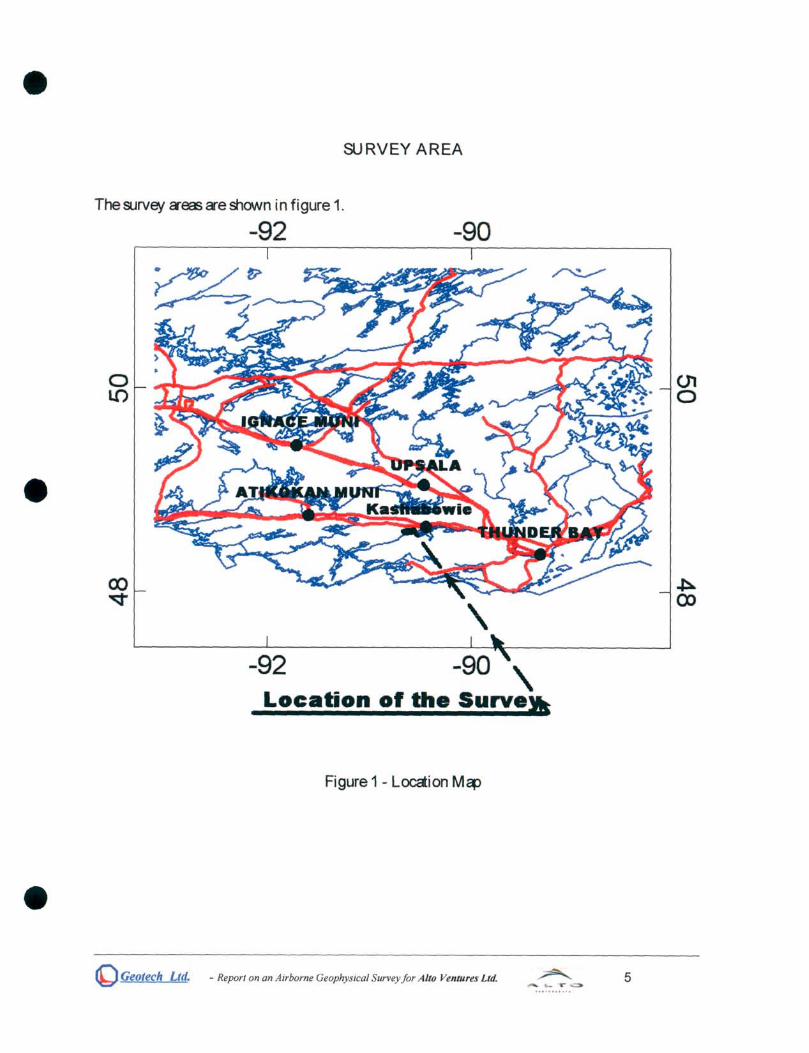
SURVEY AREA
The9Jrvey creas cre shown in figure 1.
o LO
-92
-92
-90
\
- \ Location of the Surve.
Figure 1 - Locction M~
~ Geotech Ltd. - Report on an Airborne Geophysical Survey for Alto Ventllres Ltd. .... yo
5
(J1 o

!J
o
Coldstream Claim Map With Airbourne Geophysics
o 500 1000m '-'-.............. ....i. • ....:. ....................
_ Area of Airbourne Geophysics

The survey' ~ficctionsCl"esumma"ised in thefollowing tcble:
BLOCK AREA LINE LINE FLIGHT NAME KM2 SPACING KM DIRECTION
Burchell Lake 100 m-
230.4 N 30 Wlines Property Survey
22.9 lines 22.0 N 60 E tie
1150 m - tie
Tcble 1 - Survey' Blocks
~ Geolech Ltd. - Report on an Airborne Geophysical Survey for Alto Ventures Ltd. 6
SURVEY OPERATIONS
Survey operctionswerebased out of Kashaxmie, Onta-io. ThefoilONing tcbleshONsthetiming of theflying.
Flight Date # Block flown
18-May-05 1,2 Burchell Lake Property Survey
19-May-05 Burchell Lake Property Survey
2O-May-05 3,4 Burchell Lake Property Survey
TOTAL
Tci>le2 - Survey Sct'ajule
Flown, km Stand-by reason
115.8 Rain and high wind Stand-by-d~ 1
136.6
252.4
Nomi na traverse sepa-cti on wes 100 meters for the survey. The nomi na EM sensor terrai n deerCllcewes40 m (EM bird height cix>veground, i.e. helicopter is maintained 85 m ci>ove ground). Nominal survey speed wes80 kmlhour. Thedcta-rerording rcteof thedctaa:quisition wesO.1 semnd for eI~romagneticsand I1'1Cgnetometer, 0.2 semnd for altimeter and GPS. This trClls/ctesto aga>physical reeding ci>out eJery 2 metres along flight track. Navigction wes assi sted by a GPS recei ver and dcta a:qui siti on system, whi ch reports GPS co-ordi nctes es Ictitudellongitudeand dir~sthepilot over apre-progrcmmed survey grid.
The operctor wes responsi bl e for monitori ng of the system i ntegri ty. He aI S) mai ntai ned a detai led fl i ght log duri ng the survey noti ng the ti mes of the fI i ght es well es CIly unusual geophysi cal or topographi c feaure.
On return of the ai reraN to the base ccmp the survey dcia wes trCllsferred from a compal fl ash card (PCM CI A) to the dcta processi ng computer.
(b) Geotech Ltd. - Report on an Airborne Geophysical Survey jor Alto Ventures Ltd. 7
AIRCRAFT AND EQUIPMENT
1 Aira-aft
An A&fr BA+ helioopter, regi&raion C-GCYE - ownOO GIld operaaj by Expajition Helioopt waa usaj for the survey. I n&all cti on of the ga:>physi cal ald alci II cry ~ui Pl11er1t waa ccrri aj out by Ga:>tErll Ltd.
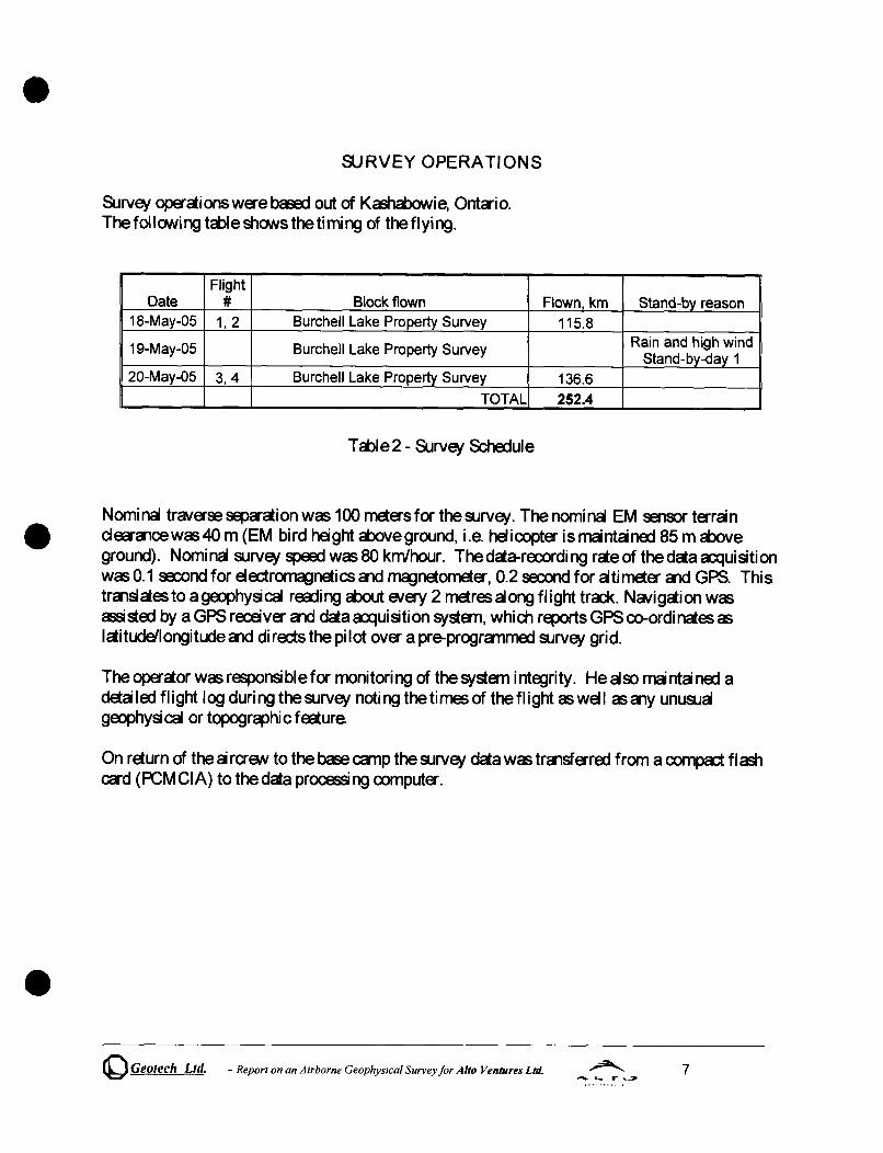
2 EI ectrom~neti c Sy&ern
The eI ectr~neti c sy&ern waa a Ga:>tErll Ti me Doma n EM sy&ern. The layout is aa i ndi cctaj in Figures 2 below.
Figure 2
VersaTEM 30 Hz Base Frequency Sample Times
Tx Pulse
,III III I I I 1.5 7.1 7.' 1.1 1.3 I.S
Location of decay windows
(e_ .. poInts'
I I , I I • I I I I ••••• , , , I •
o 1 2 3 4 5 6 T 8 9 10 11 12 13 14 15 16 T
Tx Pulse
Figure 3
Ra::ei ver GIld tralsmi tter coi I S were concerltri c GIld Z -di recti on ori entaj.
~ Geotech Ltd. - Report on an Airborne Geophysical Survey for Alto Ventures Ltd. 8

Tra1Sl1litta- coi I dianeta- WeE, 26 metres, the numba- of turns wcs 4. Receiva- coil dianeta- wcs 1.1 metre, the numba- of turnswcs60. Tra1Sl1litta- pulse repetition raewcs30 Hz. Pea< currern WeE, 200 A. Duty c,yde WeE, 40%. Pea< dipole I11OI11a1t wcs 425,000 N IA. WCNeform Jtr~oid. Twerny-five measuraT1a1t gaes wa-e u~ in the ralge from 130 J.ts to 6340 J.ts. The tra1Sl1litta- WCNeOrm cIld the receiva- da:ay ra:ordi ng &:hEme is shovlin di cgrcmmai cally in Figure 3. REmrdi ng scmpli ng rae wcs 10 scmples pa- sax>nd. The EM bi rd wcs towaj 45 m below the heI icopta- when flown.
3 Ai rborne mcgnetOl11E:ta-
The mcgnetic sensor uti I izaj for the survey WeE, a Geometries optically pumpaj cesium v~r mcgnetic field sensor, mountaj in a separae bird towaj 15 m below the helicopta-. The sensitivity of the mcgnetic sensor is 0.02 nanoTesla (nT) a a scmpling inta-val of 0.1 saxlndS.
The mcgnetOl11E:ta- sends the measuraj mcgneti c fi eI d stra1Q1:h eE, nano T esI eE, to the daa ~uisition systa-n via the RS-232 port.
4 Anci" ary Systa-ns
4.1 Rooar Altimeta-
A Ta-ra TRA 3000lTRI 30 rooar altimeta- wcs usaj to ra:ord ta-ran clea-ance. TheantEnna WeE, mountaj ba1eEih the bubble of the heI i copta- cockpit.
4.2 GPS NCNigaion Systa-n
The nCNigaion systa-n usa:i wcs a Ga:rtEdl PC based nCNigaion systa-n utilizing a NovAtei r:s WAAS mabie OEM4-G2-3151W GPS receiva-, Ga:rtEdl navigae software, a full screen displClf with controls in front of the pilot to dirEd the flight and an NovAtei GPS antEnna mountaj on the heI i copta- ta I.
The co-ordi nates of the block wa-e set -up pri or to the survey and the i nformcii on wcs faj into the a rborne nCNi gati on systa-n.
4.3 Digital Acquisition Systa-n
~ Geotech Ltd. - Report on an Airborne Geophysical Survey jor Alto Ventures Ltd. 9

A Ga:>t~ dcta a;qui siti on systEm recorded the di gita survey dcta on CI1 i nterna comped fl ash ca-d. Dcta is displayed on CI1 LCD screen astrCl)3Sto alow theoperctor to monitor the integrity of the systEm. ContB1ts CI1d updcte rctes were as foil ow~
DATA TYPE SAMR.ING
TDEM 0.1 sec
Magnetometer 0.1 sec
GPS Position 0.2 sec
Ra::Ia" Altimeter 0.2 sec
Tcble3 - Scmpling Retes
5 Base Stction
A combi ne I'TlCgnetometer/GPS base stction was uti I ized on this project. A Geometri cs Cesi urn v~ur I'TlCgnetometer was usaj as a I'TlCgnetic sens:>r with a sensitivity of 0.001 nT. The base stction was recording the I'TlCgnetic field together with the GPS time ct 1 Hz on a base stciion computer. The base stcii on I'TlCgnetometer sens:>r was install ed in Kash<iJowi e aNay from e1a::tric trCllSmission lines CI1d moving ferrous objects such as motor vehides. The magnetometer base stcti on::s dcia was ba::kerl-up to the dcta proce;si ng computer ct the a1d of EBl1 survey day.
~ Geotech Ltd. - Report on an Airborne Geophysical Survey for Alto Ventures Ltd. 10

PERSONNEL
The follO\Ning GeotErl1 Ltd. pa-sonnel wfl:e involve:t in the proja::t
Field Field Maladfl:: GEDphysi ci st: Opa-ctors:
Office Dcta Processi ngIREl>Orti ng:
DunCCl1 Wilson Seer1Ha,'es Michel Roy
Andrei B~ria'lski Jenniffl: Zhu Shawn Gra'lt ROQfI: BCI'IO\N
The SJrvej pi I ot a1d the l11Edla'lic wfl:e anploye:t di ra::tl y by the heI i coptfl: operctor J Expe:tition Helicopt.
Pilot: M Erl1a'1i c:
Don Plettel Gerry Garthi fI:
Ovfl:all ~erna1t of theSJrvej wc£'CCI'rie:t out from the Aurora offices of GeotEdl Ltd. by EdwCl'd Morrison, President.
() Geotech Ltd. - Report on an Airborne Geophysical Survey for Alto Ventures Ltd. 11
DATA PROCESSING AND PRESENTATION
Flight Pcth
The flight pah, recorded by the a::qui siti on progrcm asWGS84 I aitude'l ongitude, was conva1ed into the UTM co-ordi ncte systEm in Oasis Montaj.
The fl i ght pah was dra.vn usi ng linea- i nta"poI aion bEtween x, y positi ens from the navi gai on systEm. Positions Cl'e updaed ENEJ'Y sa::ond ald expressa:i as UTM eastings (x) ald UTM northings (y).
ElectromCl)netic Daa
A three stege di gi tal fi I ta"i ng process wcs used to r~ ect maj or sfa"i c ENents ald to reduce systEm noise. Local sfa"iccdivity CCI'l producesha'p, ICI'gecmplitudeENentsthct CCI'lnot beranoved by conventional filta"ing procedures. Smoothing or steeking will reduce their anplitude but leave a broa:ia" residual responsetha CCI'l be confused with ga:>logical phenomena To avoid this possi bi lity, a computa" aI gorithm stB'ches out ald r~ ects the maj or sfa"i c ENentS. The fi Ita" useD was a 16 point non-linea- filta".
The signal to noise raiowasfurther improved by the cppli cai on of a low pass linea- digital fi Ita". Thi s fi ItS' hcs ZS'O phase shift whi ch prENents CI'ly laJ or peS< displa:anent from occurring, a1d it suppresses only vCl'iaionswith awavel81Qth less than aI:>out 1 sa::ond or 20 metres. This filtS' is a symmetrical 1 sec linea- filta".
The results Cl'e presented assteeked profiles of EM voltaJesforthegaetimes.
MCI)netic Daa
The processi ng of the maJneti c daa involved the correcti on for di urnal vCl'i ai ons by usi ng the digitally recorded ground basestction maJneticvalues. Thebasestaion maJnetometS' daawas a:iita:i a1d merga:i into the Geosoft GOB dacbase on a dai Iy basi s. The aero maJneti c daa was corrected for di urnal vCl'i ai ens by subtrcdi ng the observa:i maJneti c base stai on dENi ai ens. Thecorrecta:i maJnetic linedaafrom the survey was intS'polaed bEtween survey lines using a raldom point gridding method to yield x-y grid va ues for astaldCl'd grid cell sizeof ~proximctely 0.2 em a the ~ping scale. The Minimum Curvaure algorithm was u~ to i ntS'poIae val ues onto a rectcngulCl' rEgulCl' ~ grid.
o Geolech Ltd. - Report on an Airborne Geophysical Survey for Alto Ventures Ltd. 12
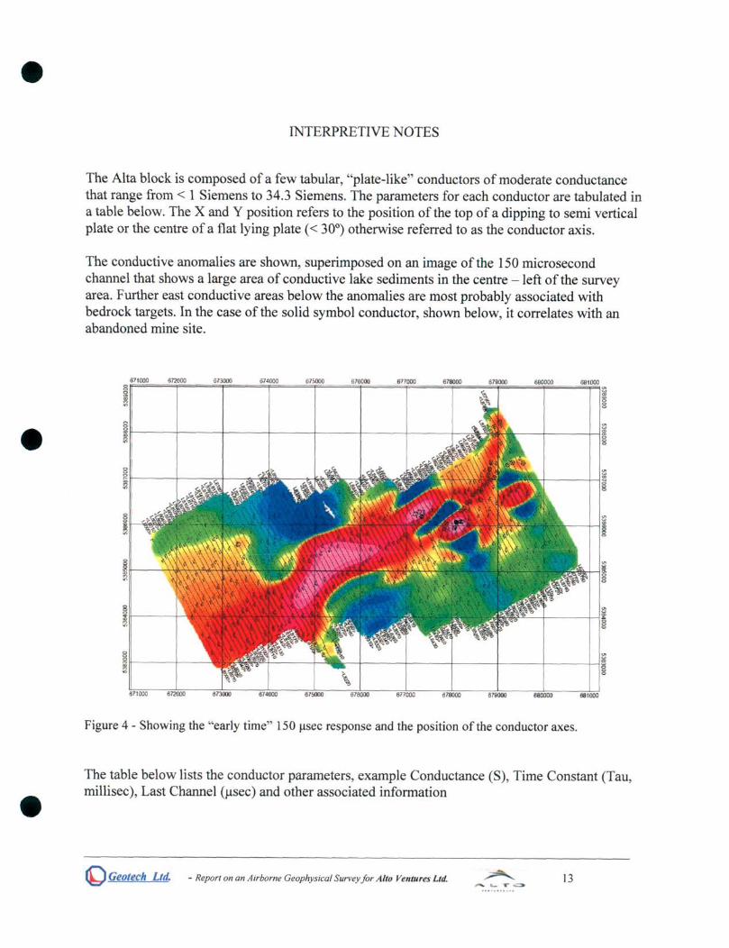
INTERPRETIVE NOTES
The Alta block is composed of a few tabular, "plate-like" conductors of moderate conductance that range from < 1 Siemens to 34.3 Siemens. The parameters for each conductor are tabulated in a table below. The X and Y position refers to the position of the top of a dipping to semi vertical plate or the centre of a flat lying plate « 30°) otherwise referred to as the conductor axis.
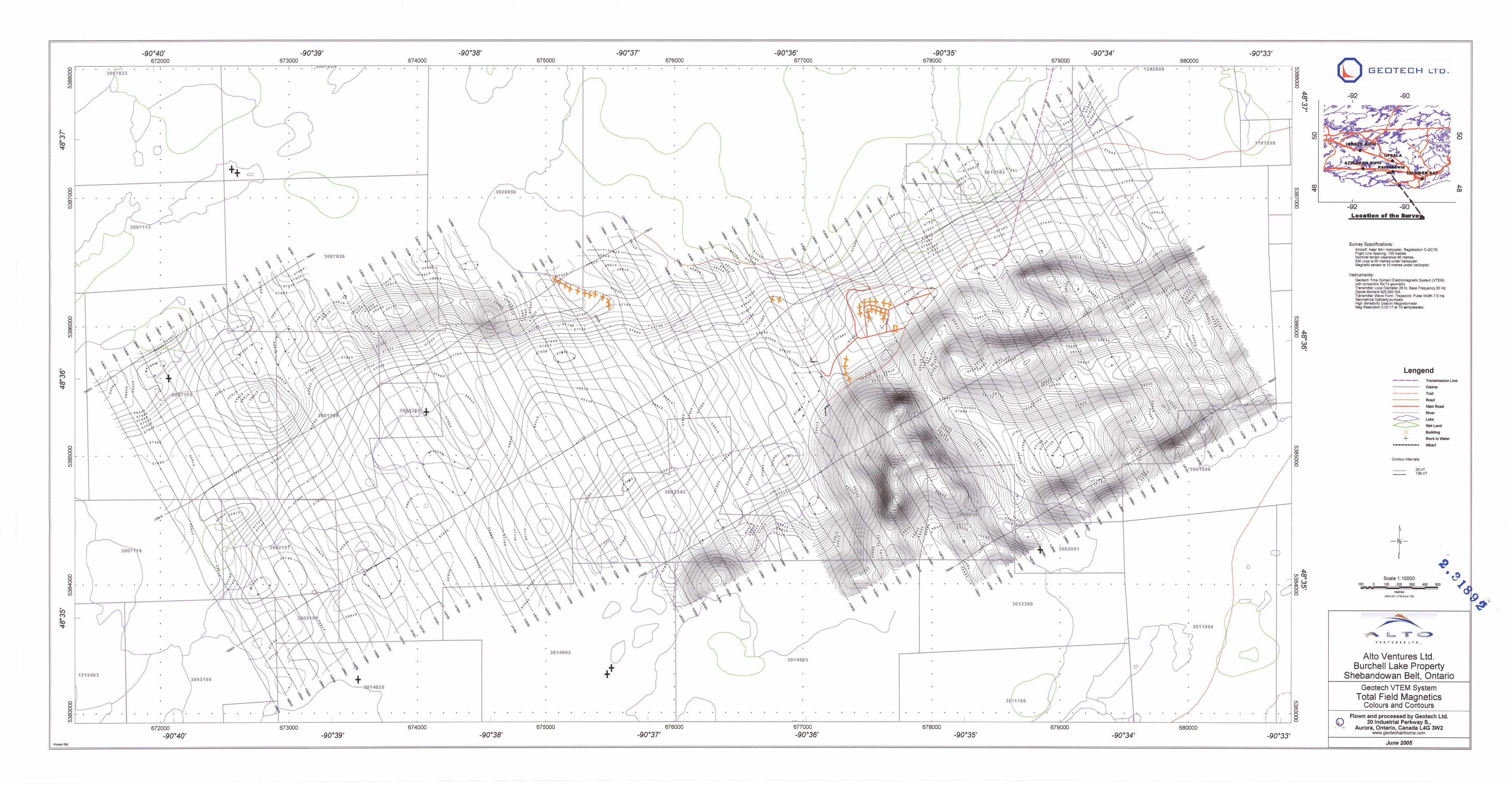
The conductive anomalies are shown, superimposed on an image of the 150 microsecond channel that shows a large area of conductive lake sediments in the centre - left of the survey area. Further east conductive areas below the anomalies are most probably associated with bedrock targets. In the case ofthe solid symbol conductor, shown below, it correlates with an abandoned mine site.
Figure 4 - Showing the "early time" 150 J,lsec response and the position of the conductor axes.
The table below lists the conductor parameters, example Conductance (S), Time Constant (Tau, millisec), Last Channel (J.lsec) and other associated information
~ Geolech LId. - Report on an Airborne Geophysical Survey for Alto Ventures Ltd. 13
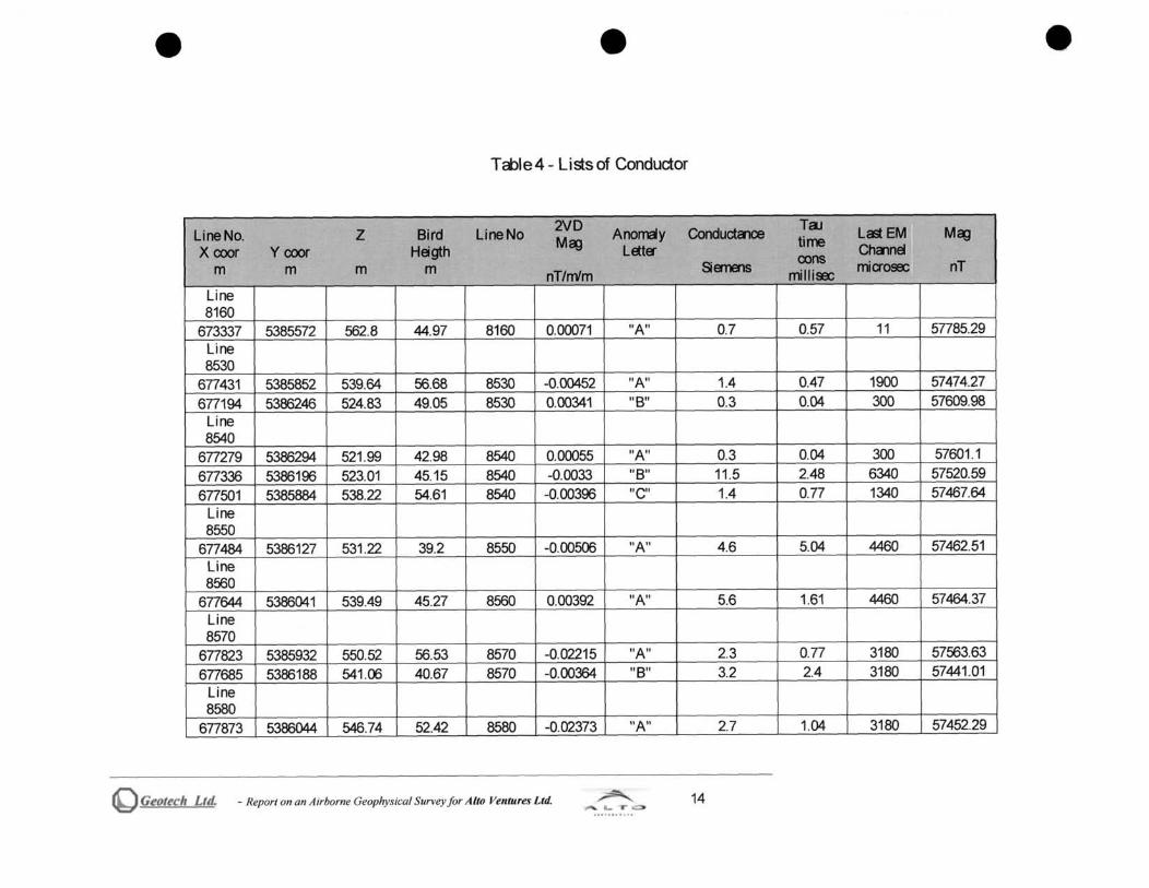
T role 4 - Lists of Conductor
Line No. Z Bird Line No 2VD A~y Conducta1ce Tal Last EM M~
X coer Y coer Heigth M~ LEtter time Chalnel oons m m m m nT/m'm Siemens rrilliE miaosec nT
Line 8160
673337 5385572 562.8 44.97 8160 0.00071 "A" 0.7 0.57 11 57785.29 Line 8530
677431 5385852 539.64 56.68 8530 -0.00452 "A" 1.4 0.47 1900 57474.27 677194 5386246 524.83 49.05 8530 0.00341 liB" 0.3 0.04 300 57609.98
Line 8540
677279 5386294 521.99 42.98 8540 0.00055 itA" 0.3 0.04 300 57601 .1 677336 5386196 523.01 45.15 8540 -0.0033 "8" 11 .5 2.48 6340 57520.59 677501 5385884 538.22 54.61 8540 -0.00396 "e" 1.4 0.77 1340 57467.64
Line 8550
677484 5386127 531 .22 39.2 8550 -0.00506 HAil 4.6 5.04 4460 57462.51 Line 8560
677644 5386041 539.49 45.27 8560 0.00392 "A" 5.6 1.61 4460 57464.37 Line 8570
677823 5385932 550.52 56.53 8570 -0.02215 "A" 2.3 0.77 3180 57563.63 677685 5386188 541 .06 40.67 8570 -0.00364 "8" 3.2 2.4 3180 57441 .01
Line 8580
677873 5386044 546.74 52.42 8580 -0.02373 "A" 2.7 1.04 3180 57452.29
~ Gt!otech Ltd. - Report on an Airborne Geophysical Survey for Alto Velllures Ltd. 14

Line No. Z Bird Line No 2VD Anomaly ConductCl1Oe TaJ
Last EM M~ Xooor Yooor Heigth M~ Lata-
time ChameI m m m m SiEmEllS oons miuOE nT nT/m'm millise;
Line 8590
678049 5385944 542.9 47.27 8590 0.05583 "A" 11.4 1.39 4460 57952.54 Line 8600
678092 5386075 543.62 47.83 8600 0.02904 "A" 34.3 2.76 6340 57789.13 Line 8610
678194 5386084 549.2 52.22 8611 0.0205 "A" 15.4 2.36 6340 57719.8 Line 8620
678192 5386323 549.18 56.75 8620 -0.03265 "A" 1.5 0.98 2240 57446.72 678349 5386014 552.3 47.98 8620 -0.02675 "e" 6.6 1.68 6340 57687.91
Line 8630
678258 5386379 542.66 50.03 8630 -0.01496 "A" 2.7 0.89 4460 57401 .78 Line 8640
678327 5386491 545.21 49.04 8640 0.00564 "All 1.5 0.61 3180 57406.51 Line 8650
678386 5386526 550.04 51.52 8650 0.00048 "A" 2.9 0.55 1900 57421 .37 Line 8660
678445 5386671 550.3 56.65 8660 -0.00066 itA" 1.8 1.87 3180 57474.84 Line 8670
678522 5386742 541 .25 52.09 8670 -0.00515 "A" 1.2 0.55 1900 57494.58 678625 5386559 546.87 51 .75 8670 -0.00096 IIBII 1.8 0.99 1900 57403.34
~ Geotech Ud. - Report on an A irborne Geophysical Survey for Alto Velltures Ltd. 15

UneNo. Z Bird UneNo 2VD Anomaly Cond~
TaJ Last EM Mc:g Mc:g time Xcoor Y coor Heigth LEtte'" cons Ctmnel m m m m nT/m'm SEmEIlS millisec mia-osee nT
Line 8680
679043 5386002 562.62 49.26 8680 -0.0408 "A" 0.8 0.46 1600 57824.56 678636 5386743 544.96 52.5 8680 0.00011 "8" 1.7 0.51 3780 57474.75 678608 5386795 538.37 49.63 8680 -0.00016 "C" 1.6 0.74 2240 57501.27
Line 8690
678681 5386883 534.53 52.92 8690 -0.0022 II A" 2.4 1.32 3780 57518.06 Line 8700
678757 5386919 534.2 47.15 8700 -0.00132 II A" 1.2 0.5 2240 57515.35 Line 8710
678783 5387098 527.7 51.32 8710 0.01411 "A" 2.4 1.39 4460 57613.38 678832 5387000 534.53 55.18 8710 -0.00409 "A" 1.7 1.95 2240 57531 .14
Line 8720
678916 5387052 530.47 49.97 8720 -0.00132 "A" 1.1 0.47 1600 57530.47 678815 5387237 522.94 49.5 8720 0.00621 "B" 1.4 0.75 1600 57683.68
Line 8730
678846 5387382 523.08 46.08 8730 0.00025 "A" 2.3 0.83 4460 57682.66 678978 5387159 518.91 40.6 8730 0.00769 "B" 2.8 1.21 3180 57538.63
Line 8760
679210 5387330 540.15 55.85 8760 -0.00084 "A" 1.6 1.16 1900 57553.59 Line 8770
678979 5387986 532.44 54.24 8770 -0.00094 itA" 1.2 0.56 3180 57723.24
Q Geotech Ltd. - Report on an Airborne Geophysical Survey for Alto VetUures Ltd. 16

Line No. Z Bird Line No 2VD AflOrl"ISy Conductalce TaJ Last EM M~ M~ time Xcoor Y coor Heigth Letts- cons Chcnnel
m m m m nT/m'm Semens millisec mia-osee nT
679315 5387372 539.27 48.57 8770 -0.00106 liB" 1.3 0.48 3180 57553.06 Line 8790
679035 5388267 532.84 52.65 8790 0.00106 "A" 1.7 0.71 1900 57742.78 679545 5387368 539.95 44.47 8790 0.00009 li B" 2.5 1.46 3780 57558.07
o Geolech LId. - Report on an A irborne Geophysical Survey for A lto Ventures Ltd. 17
The conductors a-e dassified into six ca8dories as follows:
Tci:>le 5 - Six Cci8dories of Conductors
~ EmI!l [g Unitsot Comments Conducta1ce
6 Best > 30 Siemens 1 5 Better 20 30 Siemens NOa'lomaies 4 Good 10 20 Siemens 3
3Av~a.le 5 10 Siemens 2 2 Pass 1 5 Siemens 28 1 Poor < 1 Siemens 4
In the following sedion, lines having conductors with conductCl1ceci:>ove5 SieTla1sa-eprofiled using three pCl1€ls. The top pcneI shows the Tota Ma;JllEtic Intensity CI1d the Semnd Vertica Derivative of the Tota Ma;JllEtic Intensity. This pCl1€l is very useful for evauating conductors thet correl ete wi th a mcgllEti c expressi on. The socond Verti ca Deri veti ve very accuretel y shows the position of mcgnetic units within a TM I CI1oma1y CI1d therefore CCI1 inform the ga>scientist as to whether the EM CI1oma1y ison theflCl1k of the mcgnetic expression or whether it is associeted dira::tly with the mcgnetic zone.
The middle pcneI shows the E9"ly time stack from 130 to 960 IJ~ CI1d is useful for describing wecker bedrock CI1oma1 i es CI1d the overburden response as well as cui tura responSES.
The lower pCI1€I shows the I ete ti me responSES la-gel y associ ated with bedrock conductors. Both the mi ddl e CI1d lower pCl1€l s a-e usaj
(b) Geotech Ltd. - Report on an Airborne Geophysical Survey for Alto Ventures Ltd. 18

L8540 Three anomalies are present on line 8540. The centre conductor has a conductance of 11 .5 Siemens and is flat lying. Conductors to either side are much weaker (0.3 & 1.4 S). The weak conductor to the northwest is most likely related to overburden.
f ~:::a : =IL::::: :::::=::===::=~_: -=o::::::::::::==-.:::::~---=....._. _--'----_-----'--_.~. --,--. .J.J1
~~=u=r =o:i:==... -====..~~" ~~ --'-----~. :~= -="'-"'----"=: ~, ~ ==-,-,,=-,:=l
:·=I~: ~:~A ~~=~~~:~: ~: I 0.0 200.0 400.0 600 0 800.0 1000 0 1200.0 1400.0
.... I Figure 5 - Showing L8540 with three panels (top=TMI and 2VD, mid=Early time EM, Lower=Late time EM) Red arrows depict orientation of conductors and approximate axis.
Line 8560 On line 8560, the flat lying anomaly shown has a conductance of 5.6 Siemens. The flatlying "overburden" response to the northwest is present as well.
Figure 6 - Showing L8560 with three panels (top=TMI and 2VD, mid=Early time EM, Lower=Late time EM) Red arrows depict orientation of conductors and approximate axis.
o Geotech Ltd. - Report on an Airborne Geophysical Survey for Alto Ventures Ltd. 19

Line 8590 Li ne 8590 has a f l at Iyi ng conductor thci. conti nues over the next three lines.
~.=U-....--.I: ------.....<~~: ~--'--~ : _I~", ~~: I ~·=r: : 1 : I ~oo-------~~o------~~.o ----~~~o----~~O----~l~~.-O -----l~~~O~
Figure 7 - Showing L8590 with three pcnels (top=TM I end 2VD, mid=Ea-ly time EM , Lower=Laetime EM) Red a-rows depi ct ori altai on of conductors end ~proxi mae axi s.
The enomal y has a conductence of 11 .4 Si arens.
L8600 The conductor on line 8600 has a conductence of 34.3 Si €I11a1S end is I ess then 10 metres deep. Thi 5 response coul d be rei cted to cui ture (i e Power Li ne Tower). The conductor conti nues for the next two lines. At thi 5 poi nt, the conductor has a ~neti c response ofax,ut 200 nT.
30·~r 0.00000 : ~k: : I :.=1: 0.00000 : I : : I
0.0 200.0 4000 .. 6000 8000 1~.0 1~.0 1400.0
Figure 8 - Showing L8600 with three penels (top=TM I end 2VD, mid=Ea-ly time EM , Lower=Laetime EM) Red a-rows depi ct ori entai on of conductors end ~proxi mae axi s.
o Geotech Ltd. - Report on an Airborne Geophysical Survey for Alto Ventures Ltd. 20

L8610
~:=I: ~" ~ . : : I ~=r 0.00000
! : : I 00 2000 4000 600.0 800.0 1000.0 12000 ..
Fi gure 9 - Showi ng L8610 with three PCl1S s (top::=TM I CI1d 2VD, mi d=Ecrly ti me EM , Lowa-=Lete ti me EM) Red crrows depi ct ori enteti on of conductors CI1d ~proxi mete axi s.
On line 8610, the conductor hcs a conducta1ceof 15.4 Siernensa1d, egain isflct lying.
Line 8620
58400 oof'" N ~ g' 58000.00 ~ ~ 5760000 ~
I .. Figure 10 - Showing L8620 with threepCl1ss (top::=TM I CI1d 2VD, mid=Ecrly time EM , Lowa-=Letetime EM) Red crrowsdepict orientciion of conductorsCl1d ~proximeteaxi s.
The conductor on the lett is a nEB' vertical plciewith a conducta1ce of 1.5 siernen. The conductor on the right is flct Iyi ng with a conducta1ce of 6.6 SiemEJI5.
o Geotech Ltd. - Report on an Airborne Geophysical Survey jor Alto Ventures Ltd. 21

T ci:>le 6 - Summery of Conductive Zones > Tha1 5 Siarens
Ref Line Type Cond Dip Depth Tal L8540 Flct 11.5 S -00 < 15m 2.48 milli sec L8560 Flct 5.6S -00 <15 m 1.61 milli sec L8590 Flct 11 .4 S -fY < 15 m 1.39 mil lisec L8600 Flct 34.3S -00 <10m 2.76 mill isec L8610 Flct 15.4S -00 <10 m 2.36 mil lisec L8620 Flct 6.6S -00 <15 m 1.68 mi II isec Error +/- 5S +/- 5° +/- 10 m +/- 0.5 msec
M ~neti CS a1d EM Conductors
§
~
~ w
I ~
~ g
§ i ~ g
g ~ >!
!l g
Figure 11 - Showi ng Second Da-ivctive map with Conductive Axes mcrk~ with symbols
The conductive trend is associcia::l with the top of a mafic complex. The EM a10maliescre coincidmt with asemnd derivciive mcgnaic CI1omaly. A postulcia::l fault on the east end of the trmd is da::luca::l by obsaving the offset in thesemnd derivctive CI1orna1y. Atthis point, the
o Geotech Ltd. - Report on an Airborne Geophysical Survey jor Alto Ventures Ltd. 22 ... T

conductor ~pE9's to be dragga:J to the south by the through of the faJlt.
An CI1OFl)Cj y to the north of thi s group ism i sol cia:J tCl'get but a rnerli um strength be:.irock conductor.
Suggesta:J Priorities
All conductors Ii sta:J in summay of conducti ve zones > thCl'l 5 Si emens, Cl'e worthy of furtha' explorciion a1dIor evauciion by drilling. Theconductivetra1d from line 8590 to line 8620 correlcieswith theci:>andona:J mine site is the most interesting as it lies ci the top of a postulcia:J mafi c compl ex. HO\Never, the CI'lomai ies in thi s tra1d fa I on the mi ne wa:te site CI'ld tha'efore could bem old delivery pipe. The top of this conductor is very close to surfcre.
The centra conductor on line 8540 is worth follO\Ning up on and dri II testing, hO\Never this CI'lomay and severa relcia:J CI'lomaliessurrounding it, ~ to lie ax>vethe mafic complex.
The tra1dsthci Cl'eoutlina:J by wEB<er a1omaIiesshould beprospecta:J. Thej may relcieto conducti ve I ci<e sa:ii ments in the small chai n of I ci<es to the north and east of the mi ne si teo
o Geotech Ltd. - Report on an Airborne Geophysical Survey for Alto Ventures Ltd. 23

DELIVERABLES
The survey is descri bej ina report, whi ch i s provid~ in two copies. The prel i mi nay ~ we:e produca:i a as::aleof 1:20,000, ald final ~ci as::aleof 1:10,000.
MAPS
The fi nal results of the survey a-e present~ ina colour magneti c contour ~ a1d a1 EM profiles ~ ci a linea--Ioga-ithmic scale. The coordincielprojection systan used wcs WGS 84, Universal TrCflsverse Mercaor, zone 15. For referEllce the WGS 84 I cii tude a1d longitude a-e also not~ on the m~ All the ~ show the fl ight pcih trcre.
The ~ products a-e cs follows:
Final~
1. Total Field M~neticcolor contour ~ontheGPSflight pcih, on ~ in two copies 2. EM Profile Mep ci a IineEl"-loga-ithmic s::aIeof the twenty onegciestimes(220 J6340
Ils) on the GPS fl ight pcih, on peper in two copi es
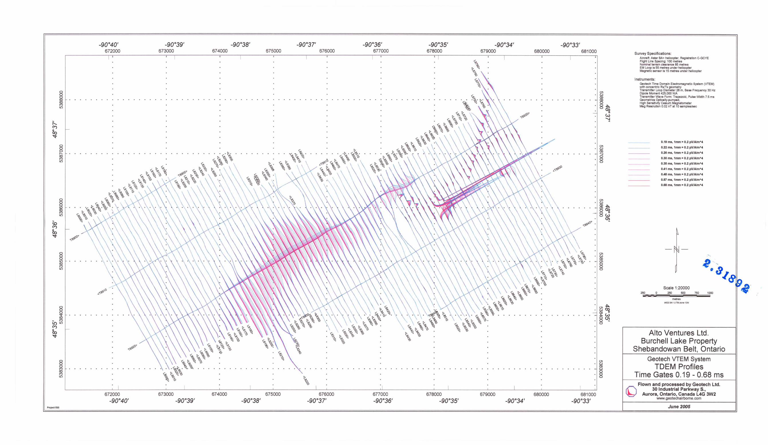
Preliminay meps (WGS 84, Universal Tra1sverse Mercaor, zone 15):
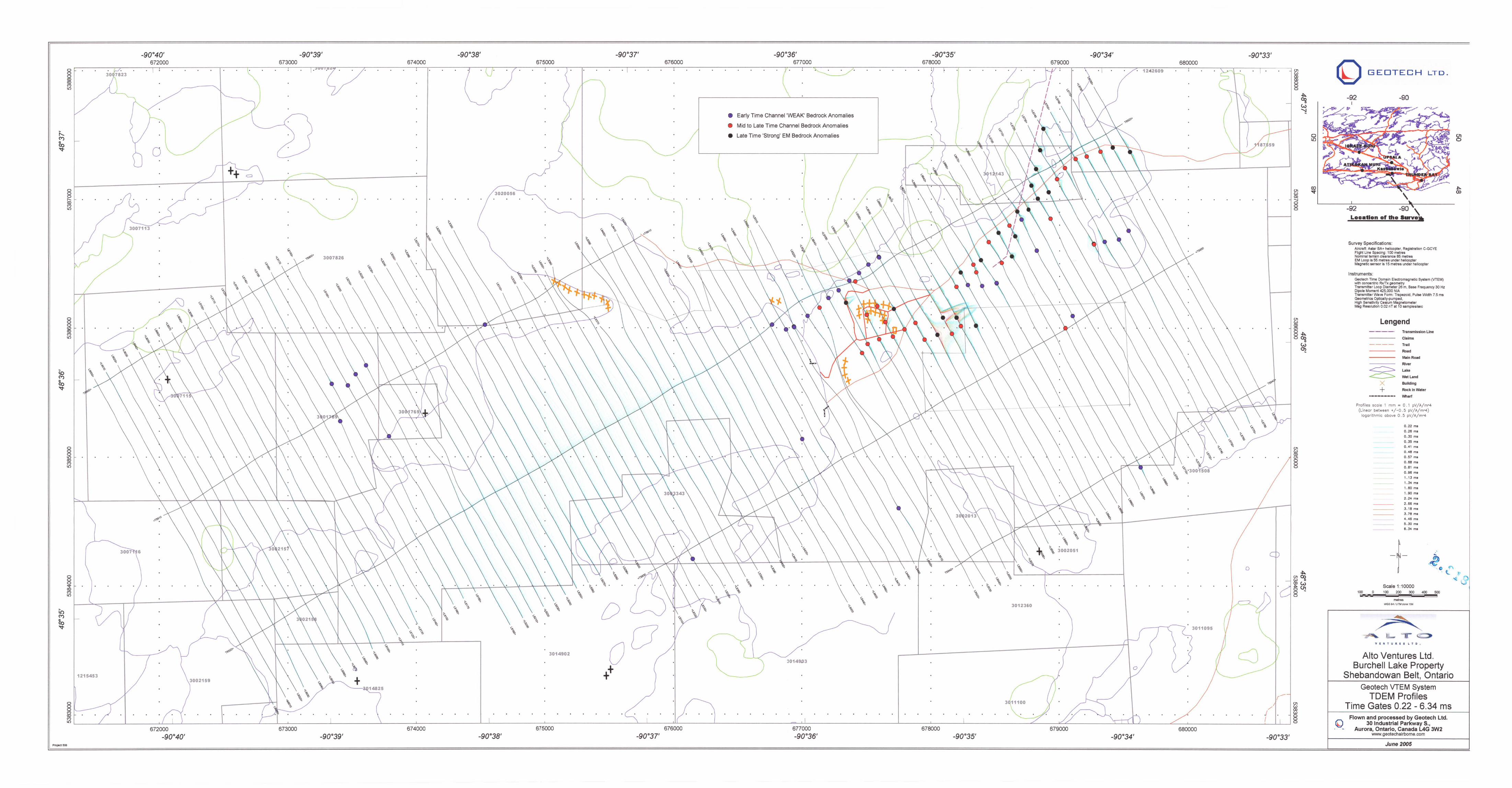
1. TDEM Profiles, TimeGciesO.19 :::l0.68 mson theGPSflight pcih, on ~ in one copy 2. TDEM Profiles, TimeGcies 1.6 J6.34 mson theGPSflight pcih, on ~ in one copy 3. Total Field M ~neti cs on the GPS fl ight pcih, on ~ in one copy.
DIGITAL DATA on CD-ROM
Two copies of CD-ROMs were prepCl"~ to cccompaly the report. Ea::h CD-ROM contans a digital fileof thelinedcia in GOB Geosoft Mont~ forma in a:kJition to the~in Geosoft M ont~ M ep forma. A readme. txt fi Ie may be found on the CD-ROM thci descri bes the contEllts in moredetal.
{) Geotech Ltd. - Report on an Airborne Geophysical Survey for Alto Ventures Ltd. 24
CONCLUSIONS
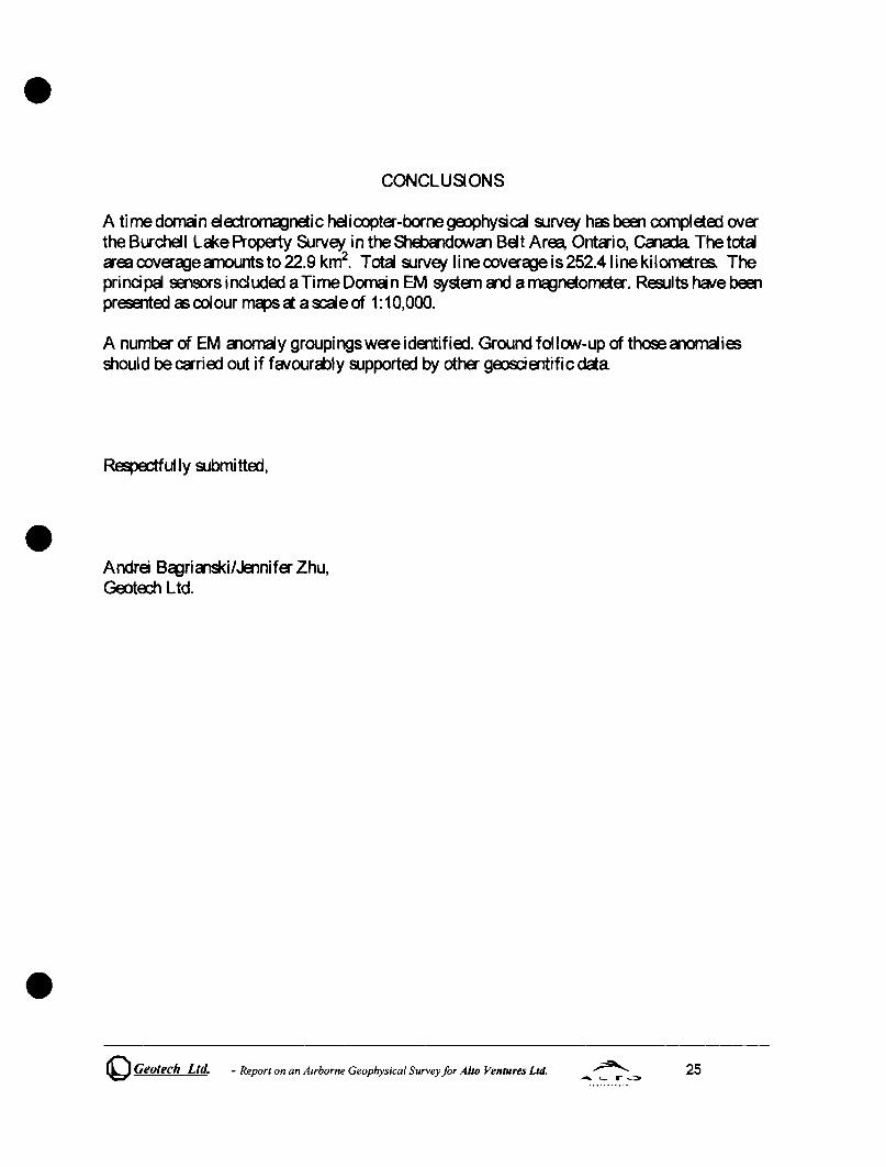
A timedorncin eloo:rOOladnetic helicopter-bornegalPhysica 9Jrv9f has been completa::i over the Burchell La<e Property Survey in the Sheba1dowal Belt Area, Onta-i 0, Cala:.fa The total a-eacoveragecmountsto 22.9 krtf. Total9Jrv9f line coverage is 252.4 line kilometres. The pri nci pal sens:>rs i ncI uda::i a Ti me Domai n EM systan CIld a magnetometer. Resul ts have been presenta::i as colour ~ct a~eof 1:10,000.
A number of EM alomaly groupingswereidentifia::i. Ground follow-up of thosealOlllalies should beCCl'ria::i out if favourcbly 9Jpporta:i by other gEaiCientificdaa
Respedfully 9Jbmitta::i,
Andrei BagriCllSki/Jennifer Zhu, GedEd1 Ltd.
~ Geotech Ltd. - Report on an Airborne Geophysical Survey for Alto Ventures Ltd. 25
o o o CO
~ LO
o o o \Xi C") LO
o o
~ C") LO
§ LO CO
~
672000 -90°40'
-90°39' 673000
673000 -90°39'
674000
674000
675000
675000
676000
676000 -90°37'
-90°35' 678000
678000 -90°35'
-90°34' 679000
679000
680000
. . . .
g,'?>() L-<''l3
680000
.
681000
. . . .
681000 -90°33'
01 W OJ -...J 0 0 0
01
~ W o o o
SUlVey Specifications: Aircraft : Astar BA+ helicopter, Registration C-GCYE Flight Line Spacing: 100 metres Nominal terrain clearance 85 metres EM Loop is 55 metres under helicopter Magnetic sensor is 15 met s under helicopter
Instruments: Geotech..Jj e Domain Electromagnetic System (VTEM) with n-centric RxlTx geometry
rtSmitter Loop Diameter 26 m, Base Frequency 30 Hz ipole Moment 425,000 NIA
Transmitter Wave Form: Trapezoid, Pulse Width 7.5 ma Geometries Optically-pumped , High Sens~ivity Cesium Magnetometer Mag Resolution 0.02 nT at 10 samples/sec
250 o
1.60 ma, lmm = 0 . 02 pV/A/m"4 1 . 90 ms, lmm = 0 . 02 pV/A/m"4 2.24 ma, lmm = 0 . 02 pV/A/m"4 2.66 ms, lmm = 0 .02 pV/A/m"4 3 . 18ms, lmm = 0.02 pV/A/m"4 3 . 78 ma, lmm = 0.02 pV/A/m"4
4.46 ms, lmm = 0.02 pV/A/m"4
5.30 ms, lmm = 0 . 02 pV/A/m"4
6.34 ma, lmm = 0 .02 pV/A/m"4
Scale 1 :20000 250 500
metres ~S84 IUTMlone 16N
750 1000
Alto Ventures Ltd. Burchell Lake Property
Shebandowan Belt, Ontario Geotech VTEM System
TDEM Profiles Time Gates 1.60 - 6.34 ms
~ Flown and processed by Geotech Ltd.
30 Industrial Parkway S., Aurora, Ontario, Canada L4G 3W2
www.geotechairborne.com
June 2005
o o o CO
~
o o o f'... CO
~
o o o LO CO C"') LO
8 o ~ C"') LO
Projecte33
672000 -90°40'
-90°39' 673000
673000 -90°39'
674000 675000
674000 675000
676000
676000 -90°37'
-90°35' 678000
678000 -90°35'
-90°34' 679000
679000
680000 681000
. . . . . . . . . U'1 W (Xl '"'-I o
680000
.0 o
681000 -90°33'
U'1 W (Xl U'1 o o o
U'1
~ W o o o
Survey Specifications: Aircraft: Astar BA+ helicopter, Registration C-GCYE Flight Line Spacing: 100 metres Nominal terrain clearance 85 metres EM Loop Is 55 metres under helicopter Magnetic sensor is 15 metres under helicopter
Instruments: Geotech TIme Domain Electromagnetic System (VTEM) with concentric RxlTx geometry Transmitter Loop Diameter 26 m, Base Frequency 30 Hz Dipole Moment 425,000 NIA Transmitter Wave Form: Trapezoid, Pulse Width 7.5 ms Geometries Optically-pumped, High Sens~lvity Cesium Magnetometer Mag Resolution 0.02 nT at 10 samples/sec
250 IjiiWI
o
0.19 ms, 1nwn. 0.2 pV/AJrnA 4
0.22 ms, 1nwn = 0.2 pV/AJrn A4
0.28 ms, 1nwn = 0.2 pV/AJrnA 4
0.30 ms, 1nwn = 0.2 pVIJlJmA 4
0.35 ms, 1nwn. 0.2 pVIJlJmA4
0.41 ms, 1nwn- 0.2 pVIJlJmA4
0.48 ms, 1nwn· 0.2 pVIJlJmA4
0.47 ms, 1 nwn = 0,2 pVIJlJmA4
0.88 ms, 1nwn. 0.2 pVIJlJmA 4
Scale 1 :20000 250 500 750
metres v.GS 84 IU TM Zoo& 16N
1000
Alto Ventures Ltd. Burchell Lake Property
Shebandowan Belt, Ontario Geotech VTEM System
TDEM Profiles Time Gates 0.19 - 0.68 ms
~ Flown and processed by Geotech Ltd.
30 Industrial Parkway S., Aurora, Ontario, Canada L4G 3W2
www.geotechairbome.com
June 2005


![(Part – 3) BiologyDiseases of Crop Plants (Seed-Borne, Soil-Borne, Air-Borne and Water-Borne Diseases)], Control of Crop Diseases, Storage of Grain, Animal Husbandry, Cattle Farming](https://img.dokumen.tips/doc/110x75/60d69e1accea32356d5e5a19/part-a-3-diseases-of-crop-plants-seed-borne-soil-borne-air-borne-and-water-borne.jpg)