Embed Size (px)
Citation preview
Report No.: 10003Inspector: Jeff WallingEmployer: Eagle Inspection Inspection Date: 5/10/2010
ACME ChemicalsBeaumont, TX
R-3503
API Certification No. 2782
Solutions Bldg
Reactor
Inspector Signature
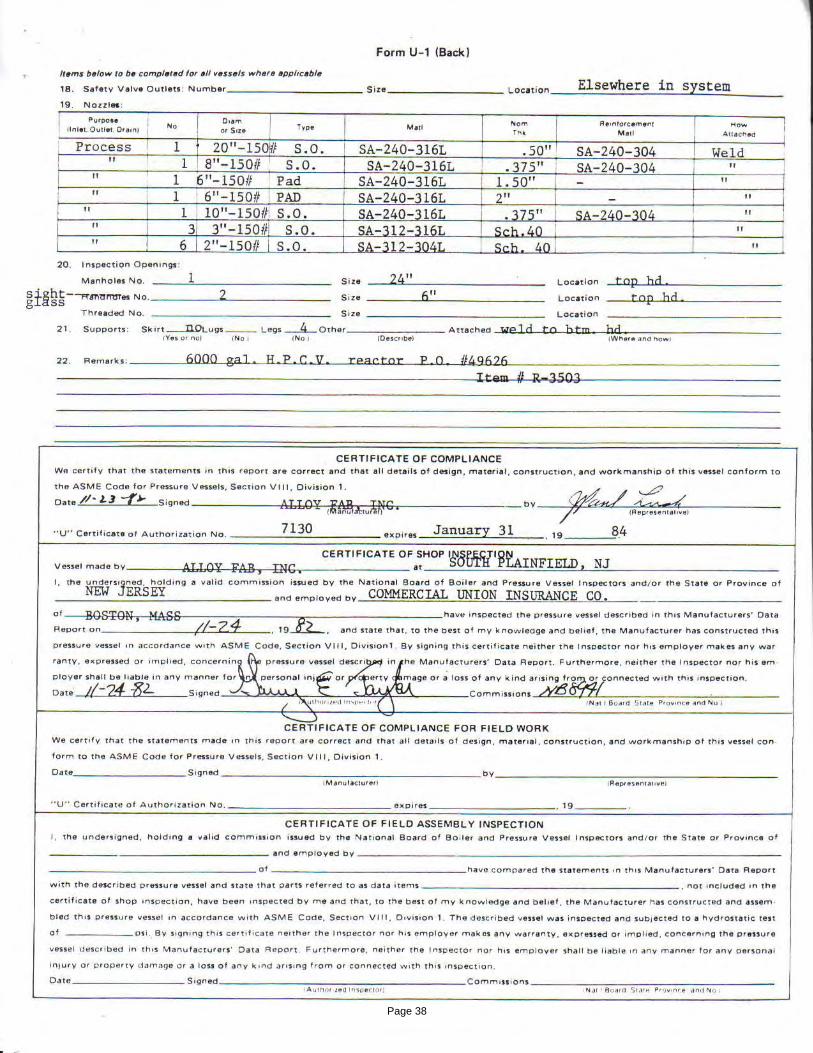
An API Standard 510 Inspection based on client criterion for nondestructive examinations was conducted on Reactor Vessel R-3503 in the ACME Chemicals facility located at Beaumont, TX on 5/10/2010. This vessel was originally built to ASME Section VIII, Divison 1. This inspection was conducted in accordance with requirements of the API-510 standard for inspections of Pressure Vessels. The following is a detailed report of the inspection including findings and recommendations.
OUT-OF-SERVICE
Inspection Report For
Report No.: 10003
Page 1
3.1 Foundation3.2 Vessel Shell 3.3 Vessel Heads3.4 Appurtenances
4.0 RECOMMENDATIONS4.1 Foundation4.2 Vessel Shell 4.3 Vessel Heads4.4 Appurtenances4.5 Next Inspection
5.0 ULTRASONIC THICKNESS MEASUREMENTS5.1 Results 5.2 Recommendations
OUT-OF-SERVICE
1.0 EXECUTIVE SUMMARY
2.0 VESSEL DATA
INSPECTION RESULTS,
TABLE OF CONTENTS
3.0
APPENDIX A
APPENDIX B
APPENDIX C
APPENDIX D
APPENDIX E
APPENDICIES Mechancial Integrity Calculations
Thickness Measurement Records
Inspection Drawings
Inspection Checklist
Manufacturers Data Sheets
APPENDIX F Inspection Photographs
APPENDIX G NDE Records
APPENDIX H References
Report No.: 10003
Page 2

1.0 EXECUTIVE SUMMARY
An API Standard 510 inspection of pressure vessel R-3503 located at Beaumont, TX was conducted on 05/10/2010. This inspection was made to collect data in order to evaluate the mechanical integrity and fitness for service of the vessel. This inspection consisted of Internal and External VT and UT (A scans) exams.
The shell has experienced significant deterioration in the form of concentrated pitting in the mid girth weld and lower shell course longitudinal welds and cracks in the baffle attachment welds that require weld repairs before placing back inservice. Nozzle N16 needs to be replaced due to deep pitting and crack in the internal surface of the nozzle.
There are some deformations of the shell congruent with the half pipe jacket layout. It appears that the shell has undergone plastic deformation due to the effects of thermal shocking (hammering) within the heating/cooling system.
This vessel has been in-service for over 28 years with 1/2 pipe jacket weld leaks possibly related to this issue (see Appendix A for Thermal Shock Stress Evaluation for a detailed discussion and evaluation). The bottom head 1/2 pipe jacket coils have several leaks throughout that need weld repair.
Recommendations in regards to thermal shock include the following:1) Review the standard operating procedures to ensure that it includes a sequencing system that maintains a slow transition between initial heating and cooling the vessel to ensure even temperature gradients in the vessel and jacketwalls.2) Strip the lower 24" to 36" of shell insulation and do a VT exam to identify leaking coil welds.3) Perform a Dye Penetrant examination of the exposed external coil attachment welds and HAZ of the shell and bottom head to identify any incipient cracking.4) Perform Brinell Hardness examination of the exposed external coil attachment welds and shell HAZ of the shell and bottom head to identify any possible hardening of the metal due to the cycle effect of the thermal shocking (hammering). BHN should be between 149 - 217 5) Schedule the next internal inspection in three years to perform follow-up NDE on shell deformations.6) Perform Dye Penetrant & Brinell Hardness examinations on the bulged areas on the internal surfaces of the vessel lower shell and bottom head at the next scheduled internal inspection.
Report No.: 10003
Page 3
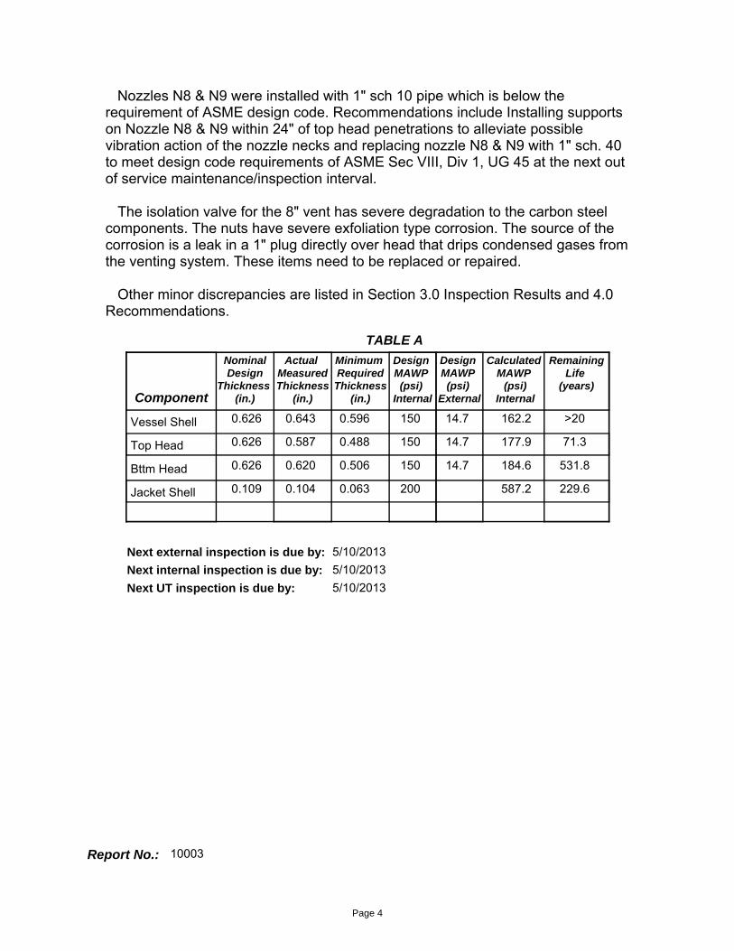
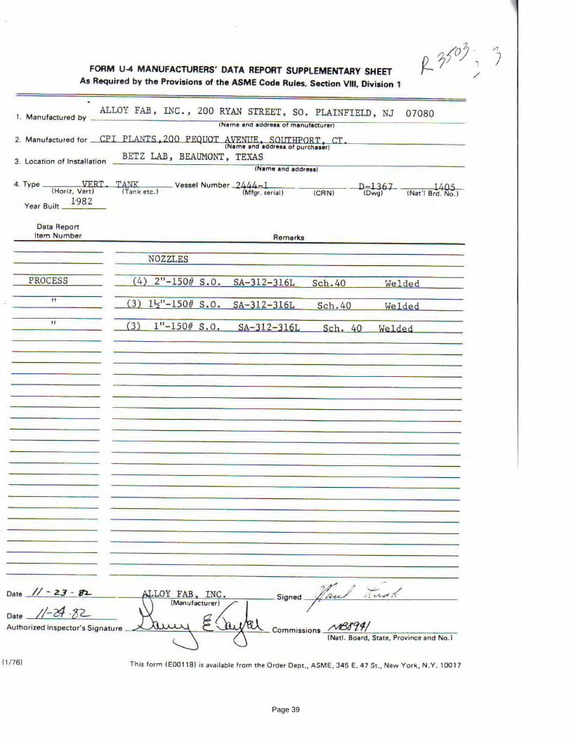
Nozzles N8 & N9 were installed with 1" sch 10 pipe which is below the requirement of ASME design code. Recommendations include Installing supports on Nozzle N8 & N9 within 24" of top head penetrations to alleviate possible vibration action of the nozzle necks and replacing nozzle N8 & N9 with 1" sch. 40 to meet design code requirements of ASME Sec VIII, Div 1, UG 45 at the next out of service maintenance/inspection interval.
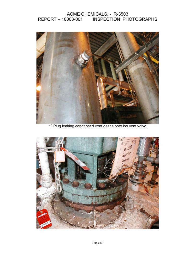
The isolation valve for the 8" vent has severe degradation to the carbon steel components. The nuts have severe exfoliation type corrosion. The source of the corrosion is a leak in a 1" plug directly over head that drips condensed gases fromthe venting system. These items need to be replaced or repaired.
Other minor discrepancies are listed in Section 3.0 Inspection Results and 4.0 Recommendations.
0.626 0.643 0.596 150Vessel Shell0.626 0.587 0.488 150Top Head0.626 0.620 0.506 150Bttm Head
Component
NominalDesign
Thickness (in.)
Actual MeasuredThickness
(in.)
Minimum RequiredThickness
(in.)
Design MAWP (psi)
Internal
Calculated MAWP
(psi)Internal
RemainingLife
(years)
TABLE A
0.109 0.104 0.063 200Jacket Shell
14.7
14.7
14.7
Design MAWP (psi)
External
>20
71.3
531.8
229.6
162.2
177.9
184.6
587.2
5/10/2013Next external inspection is due by: 5/10/2013Next internal inspection is due by:
5/10/2013Next UT inspection is due by:
Report No.: 10003
Page 4

Product: Unknown
Build Date: 1982
NB No.: 1405
Inside Dia (in.): 102
Length (in.): 165
MAWP (psi): 150
Design Temp.°F: 375
MDMT °F: -20
Oper. Press.(psi): Unknown Const Code: ASME S8 D1
Head Type: 2:1 Ellipsoidal
2.0 VESSEL DATA
Oper. Temp.°F: Unknown
Material Type: Stainless Steel
Vessel Config.: Vertical
Insul. Type: Fiberglass
Insul. Thk (in.): 2
MAWP (psi): 200
Design. Temp.°F: 375
Medium: Stm/Wtr
Oper. Press.(psi): Unknown
Oper. Temp.°F: Unknown
Material: Stainless Steel
General Data:Main Vessel Data
1/2 Pipe Jacket Data_________________________________________________________________________
Report No.: 10003
Page 5
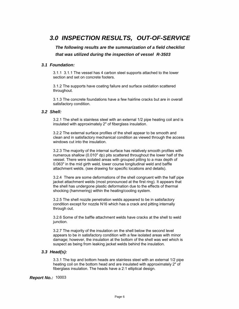
3.1 Foundation:
3.1.1 3.1.1 The vessel has 4 carbon steel supports attached to the lower section and set on concrete footers.
3.1.2 The supports have coating failure and surface oxidation scatteredthroughout.
3.1.3 The concrete foundations have a few hairline cracks but are in overallsatisfactory condition.
3.2 Shell:
3.2.1 The shell is stainless steel with an external 1/2 pipe heating coil and isinsulated with approximately 2" of fiberglass insulation.
3.2.2 The external surface profiles of the shell appear to be smooth andclean and in satisfactory mechanical condition as viewed through the access windows cut into the insulation.
3.2.3 The majority of the internal surface has relatively smooth profiles withnumerous shallow (0.010" dp) pits scattered throughout the lower half of thevessel. There were isolated areas with grouped pitting to a max depth of0.063" in the mid girth weld, lower course longitudinal weld and baffleattachment welds. (see drawing for specific locations and details).
3.2.4 There are some deformations of the shell congruent with the half pipe jacket attachment welds (most pronounced at the first ring). It appears that the shell has undergone plastic deformation due to the effects of thermal shocking (hammering) within the heating/cooling system.
3.2.5 The shell nozzle penetration welds appeared to be in satisfactory condition except for nozzle N16 which has a crack and pitting internally through out.
3.2.6 Some of the baffle attachment welds have cracks at the shell to weldjunction.
3.2.7 The majority of the insulation on the shell below the second levelappears to be in satisfactory condition with a few isolated areas with minordamage; however, the insulation at the bottom of the shell was wet which is suspect as being from leaking jacket welds behind the insulation.
3.3 Head(s):
3.3.1 The top and bottom heads are stainless steel with an external 1/2 pipeheating coil on the bottom head and are insulated with approximately 2" offiberglass insulation. The heads have a 2:1 elliptical design.
3.0 INSPECTION RESULTS,
The following results are the summarization of a field checklist
that was utilized during the inspection of vessel R-3503
OUT-OF-SERVICE
Report No.: 10003
Page 6
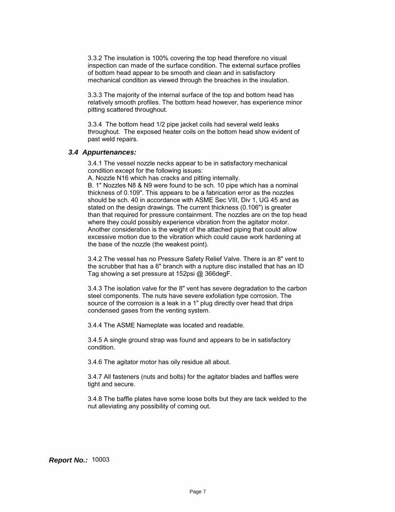
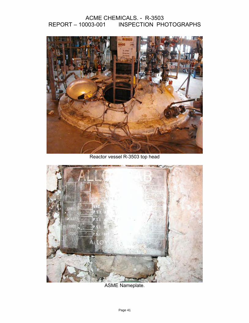
3.3.2 The insulation is 100% covering the top head therefore no visualinspection can made of the surface condition. The external surface profilesof bottom head appear to be smooth and clean and in satisfactorymechanical condition as viewed through the breaches in the insulation.
3.3.3 The majority of the internal surface of the top and bottom head hasrelatively smooth profiles. The bottom head however, has experience minor pitting scattered throughout.
3.3.4 The bottom head 1/2 pipe jacket coils had several weld leaksthroughout. The exposed heater coils on the bottom head show evident of past weld repairs.
3.4 Appurtenances:
3.4.1 The vessel nozzle necks appear to be in satisfactory mechanicalcondition except for the following issues:A. Nozzle N16 which has cracks and pitting internally.B. 1" Nozzles N8 & N9 were found to be sch. 10 pipe which has a nominalthickness of 0.109". This appears to be a fabrication error as the nozzlesshould be sch. 40 in accordance with ASME Sec VIII, Div 1, UG 45 and asstated on the design drawings. The current thickness (0.106") is greaterthan that required for pressure containment. The nozzles are on the top head where they could possibly experience vibration from the agitator motor. Another consideration is the weight of the attached piping that could allow excessive motion due to the vibration which could cause work hardening at the base of the nozzle (the weakest point).
3.4.2 The vessel has no Pressure Safety Relief Valve. There is an 8" vent to the scrubber that has a 6" branch with a rupture disc installed that has an ID Tag showing a set pressure at 152psi @ 366degF.
3.4.3 The isolation valve for the 8" vent has severe degradation to the carbon steel components. The nuts have severe exfoliation type corrosion. The source of the corrosion is a leak in a 1" plug directly over head that drips condensed gases from the venting system.
3.4.4 The ASME Nameplate was located and readable.
3.4.5 A single ground strap was found and appears to be in satisfactory condition.
3.4.6 The agitator motor has oily residue all about.
3.4.7 All fasteners (nuts and bolts) for the agitator blades and baffles weretight and secure.
3.4.8 The baffle plates have some loose bolts but they are tack welded to the nut alleviating any possibility of coming out.
Report No.: 10003
Page 7
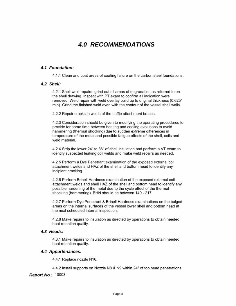
4.1 Foundation:
4.1.1 Clean and coat areas of coating failure on the carbon steel foundations.
4.2 Shell:
4.2.1 Shell weld repairs: grind out all areas of degradation as referred to onthe shell drawing. Inspect with PT exam to confirm all indication wereremoved. Weld repair with weld overlay build up to original thickness (0.625" min). Grind the finished weld even with the contour of the vessel shell walls.
4.2.2 Repair cracks in welds of the baffle attachment braces.
4.2.3 Consideration should be given to modifying the operating procedures to provide for some time between heating and cooling evolutions to avoidhammering (thermal shocking) due to sudden extreme differences intemperature of the metal and possible fatigue effects of the shell, coils andweld material.
4.2.4 Strip the lower 24" to 36" of shell insulation and perform a VT exam toidentify suspected leaking coil welds and make weld repairs as needed.
4.2.5 Perform a Dye Penetrant examination of the exposed external coilattachment welds and HAZ of the shell and bottom head to identify anyincipient cracking.
4.2.6 Perform Brinell Hardness examination of the exposed external coilattachment welds and shell HAZ of the shell and bottom head to identify any possible hardening of the metal due to the cycle effect of the thermalshocking (hammering). BHN should be between 149 - 217.
4.2.7 Perform Dye Penetrant & Brinell Hardness examinations on the bulged areas on the internal surfaces of the vessel lower shell and bottom head at the next scheduled internal inspection.
4.2.8 Make repairs to insulation as directed by operations to obtain neededheat retention quality.
4.3 Heads:
4.3.1 Make repairs to insulation as directed by operations to obtain neededheat retention quality.
4.0 RECOMMENDATIONS
4.4 Appurtenances:
4.4.1 Replace nozzle N16.
4.4.2 Install supports on Nozzle N8 & N9 within 24" of top head penetrations
Report No.: 10003
Page 8

to alleviate possible vibration action of the nozzle necks. Consider replacing nozzle N8 & N9 with 1" sch. 40 to meet design code requirements of ASME Sec VIII, Div 1, UG 45 at the next out of service maintenance/inspection interval.
4.4.3 Normally the safety relief systems should not be installed with pressure rating greater than the MAWP of the vessel (in this case 150psi at 375degF). The rupture disc install is set higher to burst by 2 psi but has a lower temperature rating (366degF) than the vessel is rated for. The rupture disc should be verified as being in code for this use. Otherwise replace it with a disc rated for 150@375degF.
4.4.3 Replace the isolation valve for the 8" vent and seal the leak in the 1"plug in the 8" vent line over the isolation valve.
4.5 Next Inspection:
5/10/2013
4.5.1 Next external inspection is due by 5/10/2013
4.5.2 Next internal inspection is due by
5/10/20134.5.3 Next UT inspection is due by
Vessel Shell4.5.4 Governing component limiting life
Report No.: 10003
Page 9
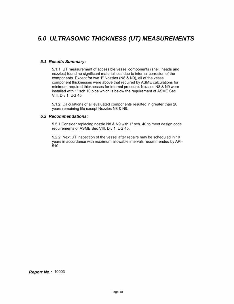
5.1 Results Summary:
5.1.1 UT measurement of accessible vessel components (shell, heads and nozzles) found no significant material loss due to internal corrosion of the components. Except for two 1" Nozzles (N8 & N9), all of the vessel component thicknesses were above that required by ASME calculations for minimum required thicknesses for internal pressure. Nozzles N8 & N9 were installed with 1" sch 10 pipe which is below the requirement of ASME Sec VIII, Div 1, UG 45.
5.1.2 Calculations of all evaluated components resulted in greater than 20 years remaining life except Nozzles N8 & N9.
5.2 Recommendations:
5.5.1 Consider replacing nozzle N8 & N9 with 1" sch. 40 to meet design code requirements of ASME Sec VIII, Div 1, UG 45.
5.2.2 Next UT inspection of the vessel after repairs may be scheduled in 10 years in accordance with maximum allowable intervals recommended by API-510.
5.0 ULTRASONIC THICKNESS (UT) MEASUREMENTS
Report No.: 10003
Page 10
APPENDIX A
1) Cylindrical Shell Calculations
2) Formed Head Calculations
3) PV Nozzle RL Calculations
4) PV Nozzle Pressure Calculation
5) Half Pipe Jacket Calculations
6) Thermal Shock Stress Analysis
Mechancial Integrity Calculations
Report No.: 10003
Page 11
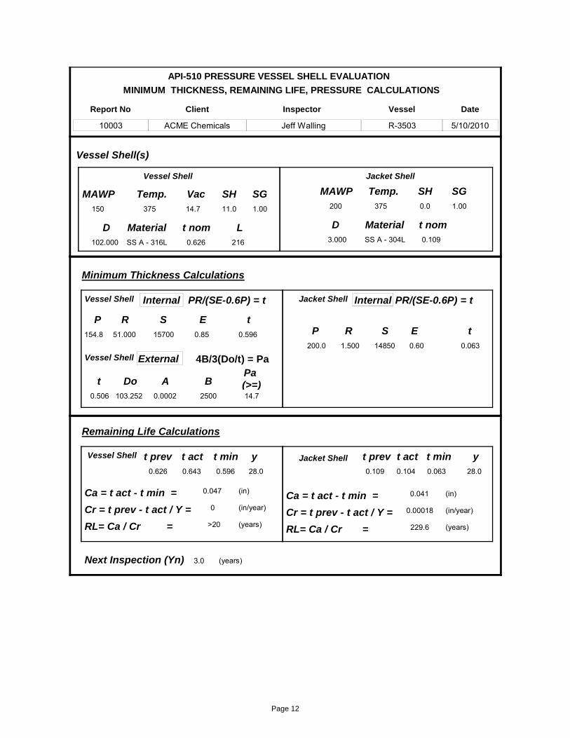
MINIMUM THICKNESS, REMAINING LIFE, PRESSURE CALCULATIONS
API-510 PRESSURE VESSEL SHELL EVALUATION
Report No
10003
Inspector
Jeff Walling
Client
ACME Chemicals
Vessel
R-3503
Date
5/10/2010
102.000
MAWP150
Temp.375
SH11.0
E0.85
t act0.643
t prev0.626
t nom0.626
L216
Do103.252 2500
MaterialSS A - 316L
A0.0002
y28.0
MaterialSS A - 304L
R1.500
P200.0
Temp.375
E0.60
t act0.104
t prev0.109
t min0.596
y28.0
t min0.063
t0.506
Vessel Shell(s)
Minimum Thickness Calculations
Internal
External
P154.8
R51.000
t 0.596
PR/(SE-0.6P) = t
Pa (>=)14.7
Internal PR/(SE-0.6P) = t
t 0.063
(in)
(in/year)
(years)
(years)
Ca = t act - t min = 0.047
Cr = t prev - t act / Y = 0
RL= Ca / Cr = >20
Remaining Life Calculations
(in)
(in/year)
(years)
Ca = t act - t min = 0.041
Cr = t prev - t act / Y = 0.00018
RL= Ca / Cr = 229.6
Vac14.7
Vessel Shell Jacket Shell
Vessel Shell
Vessel Shell Jacket Shell
Vessel Shell
D
Jacket Shell
SH0.0
t nom0.109
MAWP200
3.000
D
4B/3(Do/t) = Pa
B
15700
3.0Next Inspection (Yn)
14850
SG1.00
SG1.00
SS
Page 12
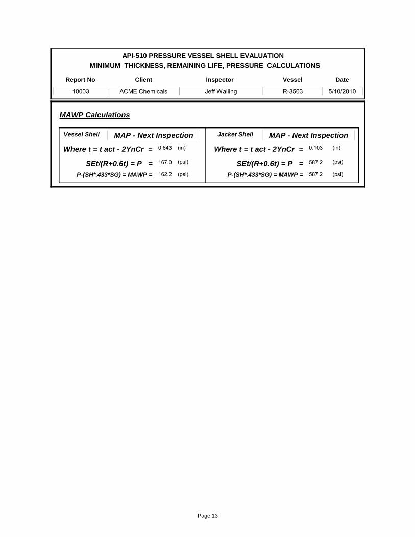
MINIMUM THICKNESS, REMAINING LIFE, PRESSURE CALCULATIONS
API-510 PRESSURE VESSEL SHELL EVALUATION
Report No
10003
Inspector
Jeff Walling
Client
ACME Chemicals
Vessel
R-3503
Date
5/10/2010
MAWP Calculations
MAP - Next Inspection
(in)Where t = t act - 2YnCr = 0.643
(psi)SEt/(R+0.6t) = P = 167.0
MAP - Next Inspection
(in)Where t = t act - 2YnCr = 0.103
(psi)SEt/(R+0.6t) = P = 587.2
Vessel Shell Jacket Shell
162.2P-(SH*.433*SG) = MAWP = (psi) 587.2P-(SH*.433*SG) = MAWP = (psi)
Page 13
MINIMUM THICKNESS, REMAINING LIFE, PRESSURE CALCULATIONS
API-510 PRESSURE VESSEL SHELL EVALUATION
Report No
10003
Inspector
Jeff Walling
Client
ACME Chemicals
Vessel
R-3503
Date
5/10/2010
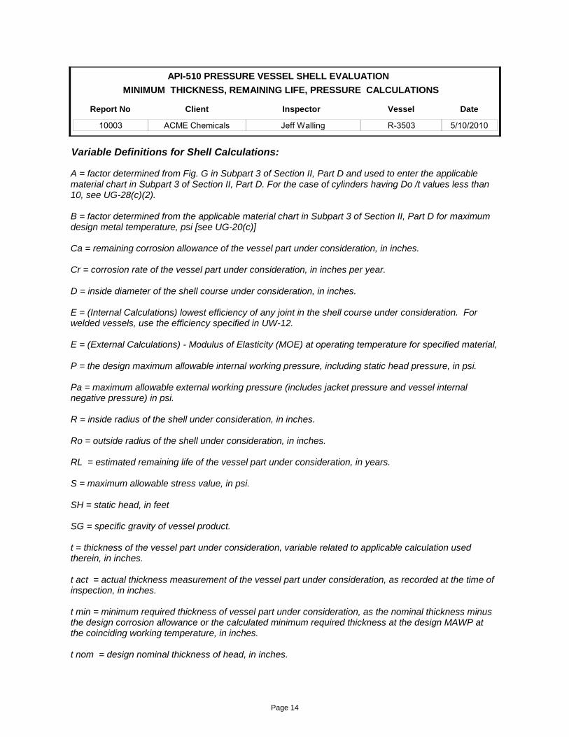
Variable Definitions for Shell Calculations:
A = factor determined from Fig. G in Subpart 3 of Section II, Part D and used to enter the applicable material chart in Subpart 3 of Section II, Part D. For the case of cylinders having Do /t values less than 10, see UG-28(c)(2).
B = factor determined from the applicable material chart in Subpart 3 of Section II, Part D for maximum design metal temperature, psi [see UG-20(c)]
Ca = remaining corrosion allowance of the vessel part under consideration, in inches.
Cr = corrosion rate of the vessel part under consideration, in inches per year.
D = inside diameter of the shell course under consideration, in inches.
E = (Internal Calculations) lowest efficiency of any joint in the shell course under consideration. For welded vessels, use the efficiency specified in UW-12.
E = (External Calculations) - Modulus of Elasticity (MOE) at operating temperature for specified material,
P = the design maximum allowable internal working pressure, including static head pressure, in psi.
Pa = maximum allowable external working pressure (includes jacket pressure and vessel internal negative pressure) in psi.
R = inside radius of the shell under consideration, in inches.
Ro = outside radius of the shell under consideration, in inches.
RL = estimated remaining life of the vessel part under consideration, in years.
S = maximum allowable stress value, in psi.
SH = static head, in feet
SG = specific gravity of vessel product.
t = thickness of the vessel part under consideration, variable related to applicable calculation used therein, in inches.
t act = actual thickness measurement of the vessel part under consideration, as recorded at the time of inspection, in inches.
t min = minimum required thickness of vessel part under consideration, as the nominal thickness minus the design corrosion allowance or the calculated minimum required thickness at the design MAWP at the coinciding working temperature, in inches.
t nom = design nominal thickness of head, in inches.
Page 14
MINIMUM THICKNESS, REMAINING LIFE, PRESSURE CALCULATIONS
API-510 PRESSURE VESSEL SHELL EVALUATION
Report No
10003
Inspector
Jeff Walling
Client
ACME Chemicals
Vessel
R-3503
Date
5/10/2010
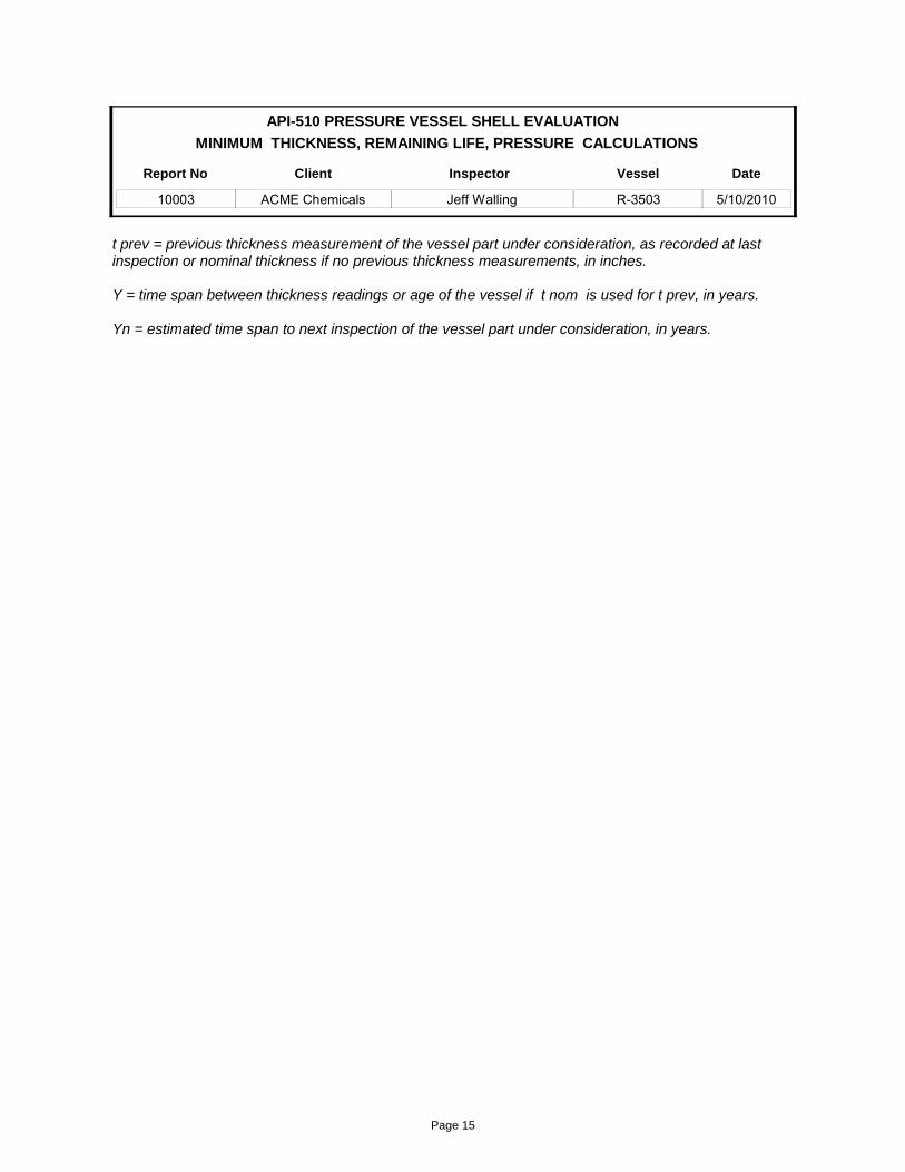
t prev = previous thickness measurement of the vessel part under consideration, as recorded at last inspection or nominal thickness if no previous thickness measurements, in inches.
Y = time span between thickness readings or age of the vessel if t nom is used for t prev, in years.
Yn = estimated time span to next inspection of the vessel part under consideration, in years.
Page 15
MINIMUM THICKNESS, REMAINING LIFE, PRESSURE CALCULATIONS
API-510 PRESSURE VESSEL HEAD EVALUATION
Report No
10003
Inspector
Jeff Walling
Client
ACME Chemicals
Vessel
R-3503
Date
5/10/2010
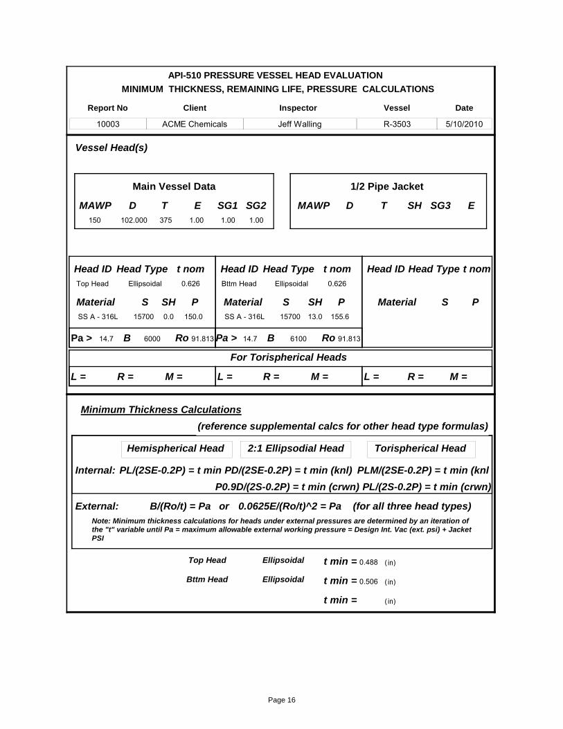
D102.000
MAWP150
T375
L =
Vessel Head(s)
Minimum Thickness Calculations
Hemispherical Head
t min = 0.488
PL/(2SE-0.2P) = t min
E1.00
DMAWP T E
Head IDTop Head
Head TypeEllipsoidal
t nom0.626
Material SS A - 316L
SH0.0
P150.0
Head IDBttm Head
Head TypeEllipsoidal
t nom0.626
MaterialSS A - 316L
SH13.0
P155.6
Head ID Head Type t nom
Material P
2:1 Ellipsodial Head
PD/(2SE-0.2P) = t min (knl)
Torispherical Head
PLM/(2SE-0.2P) = t min (knl
R =
Top Head Ellipsoidal
M =
For Torispherical Heads
L =
t min = 0.506
R =
Bttm Head Ellipsoidal
M = L =
t min =
R = M =
Internal:
B/(Ro/t) = PaExternal:Note: Minimum thickness calculations for heads under external pressures are determined by an iteration of the "t" variable until Pa = maximum allowable external working pressure = Design Int. Vac (ext. psi) + Jacket PSI
6000 6100Ro 91.813 Ro 91.813Pa > 14.7 Pa > 14.7
0.0625E/(Ro/t)^2 = Pa (for all three head types)or
(in)
(in)
(in)
SH
P0.9D/(2S-0.2P) = t min (crwn) PL/(2S-0.2P) = t min (crwn)
B B
15700 15700
1/2 Pipe JacketMain Vessel Data
SG11.00
SG21.00
SG3
S S S
(reference supplemental calcs for other head type formulas)
Page 16
MINIMUM THICKNESS, REMAINING LIFE, PRESSURE CALCULATIONS
API-510 PRESSURE VESSEL HEAD EVALUATION
Report No
10003
Inspector
Jeff Walling
Client
ACME Chemicals
Vessel
R-3503
Date
5/10/2010
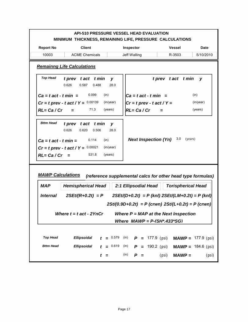
t act0.587
t prev0.626
y28.0
t min0.488
(in)
(in/year)
(years)
(years)
Ca = t act - t min = 0.099
Cr = t prev - t act / Y = 0.00139
RL= Ca / Cr = 71.3
Next Inspection (Yn) 3.0
Remainng Life Calculations
MAWP Calculations
(in) t = 0.579
Top Head
Top Head
t act0.620
t prev0.626
y28.0
t min0.506
(in)
(in/year)
(years)
Ca = t act - t min = 0.114
Cr = t prev - t act / Y = 0.00021
RL= Ca / Cr = 531.8
t = 0.619
Bttm Head
Bttm Head (in)
t actt prev yt min
(in)
(in/year)
(years)
Ca = t act - t min =
Cr = t prev - t act / Y =
RL= Ca / Cr =
t = (in)
Hemispherical Head
2SEt/(R+0.2t) = P
2:1 Ellipsodial Head
2SEt/(D+0.2t) = P (knl)
Torispherical Head
2SEt/(LM+0.2t) = P (knl)Internal
MAP
Ellipsoidal
Ellipsoidal
Where t = t act - 2YnCr Where P = MAP at the Next Inspection
2St/(0.9D+0.2t) = P (crwn) 2St/(L+0.2t) = P (crwn)
(reference supplemental calcs for other head type formulas)
Where MAWP = P-(SH*.433*SG)
(psi)P = 177.9
P = 190.2 (psi)
P = (psi)
MAWP = (psi)
(psi)
(psi)
MAWP =
MAWP =
177.9
184.6
Page 17
MINIMUM THICKNESS, REMAINING LIFE, PRESSURE CALCULATIONS
API-510 PRESSURE VESSEL HEAD EVALUATION
Report No
10003
Inspector
Jeff Walling
Client
ACME Chemicals
Vessel
R-3503
Date
5/10/2010
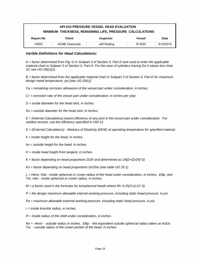
A = factor determined from Fig. G in Subpart 3 of Section II, Part D and used to enter the applicablematerial chart in Subpart 3 of Section II, Part D. For the case of cylinders having Do /t values less than 10, see UG-28(c)(2).
B = factor determined from the applicable material chart in Subpart 3 of Section II, Part D for maximum design metal temperature, psi [see UG-20(c)]
Ca = remaining corrosion allowance of the vessel part under consideration, in inches.
Cr = corrosion rate of the vessel part under consideration, in inches per year.
D = inside diameter for the head skirt, in inches.
Do = outside diameter for the head skirt, in inches.
E = (Internal Calculations) lowest efficiency of any joint in the vessel part under consideration. For welded vessels, use the efficiency specified in UW-12.
E = (External Calculations) - Modulus of Elasticity (MOE) at operating temperature for specified material.
h = inside height for the head, in inches.
ho = outside height for the head, in inches.
H = inside head height from tangent, in inches.
K = factor depending on head proportions D/2h and determined as 1/6[2+(D/2h)^2]
Ko = factor depending on head proportions Do/2ho (see table UG 33.1)
L = Hemi. Hds - inside spherical or crown radius of the head under consideration, in inches,. Ellip. and Tor. Hds - inside spherical or crown radius, in inches,
M = a factor used in the formulas for torispherical heads where M= 0.25(3+(L/r)^.5)
P = the design maximum allowable internal working pressure, including static head pressure, in psi.
Pa = maximum allowable external working pressure, including static head pressure, in psi.
r = inside knuckle radius, in inches.
R = inside radius of the shell under consideration, in inches.
Ro = Hemi - outside radius in inches. Ellip. - the equivalent outside spherical radius taken as KoDo. Tor. - outside radius of the crown portion of the head, in inches.
Varible Definitions for Head Calculations:
Page 18
MINIMUM THICKNESS, REMAINING LIFE, PRESSURE CALCULATIONS
API-510 PRESSURE VESSEL HEAD EVALUATION
Report No
10003
Inspector
Jeff Walling
Client
ACME Chemicals
Vessel
R-3503
Date
5/10/2010
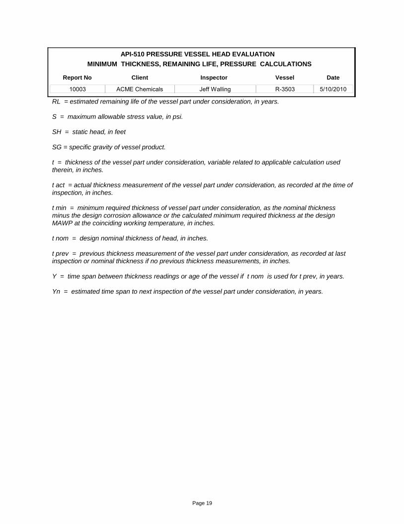
RL = estimated remaining life of the vessel part under consideration, in years.
S = maximum allowable stress value, in psi.
SH = static head, in feet
SG = specific gravity of vessel product.
t = thickness of the vessel part under consideration, variable related to applicable calculation used therein, in inches.
t act = actual thickness measurement of the vessel part under consideration, as recorded at the time of inspection, in inches.
t min = minimum required thickness of vessel part under consideration, as the nominal thickness minus the design corrosion allowance or the calculated minimum required thickness at the design MAWP at the coinciding working temperature, in inches.
t nom = design nominal thickness of head, in inches.
t prev = previous thickness measurement of the vessel part under consideration, as recorded at last inspection or nominal thickness if no previous thickness measurements, in inches.
Y = time span between thickness readings or age of the vessel if t nom is used for t prev, in years.
Yn = estimated time span to next inspection of the vessel part under consideration, in years.
Page 19

Minimum Thickness Determinations:
a) The following nozzle minimum thicknesses are based on current ASME Standards. Minimum thickness allowed for nozzles walls are based on standard pipe thicknesses minus 12.5% or connecting shell/head required thickness whichever is smaller. (ASME Sect VIII, UG-45)
b) Large size nozzles or nozzles subject to high pressures are calulated per ASME Sect VIII, DIV 1, UG-27 as follows: PR/SE-0.6P = t.
Size 2" 3" 4" 6" 8" 10" 12"t min 0.135" 0.189" 0.207" 0.245" 0.282" 0.319" 0.328"
>12"0.328"
1"0.116"
3/4"0.100"
1.5"0.127"
MINIMUM THICKNESS, REMAINING LIFE, PRESSURE CALCULATIONS
API-510 PRESSURE VESSEL NOZZLE EVALUATION
Report No
10003
Inspector
Jeff Walling
Client
ACME Chemical
Vessel
R-3503
Date
5/10/2010
Size t prev t act t min Ca Cr RL
Nozzle Remaining Life Calculations:
Noz ID MaterialTML AgeMW1 0.513 0.185 0 >2028.0 0.50024008 SS A - 316L 0.328N1 0.529 0.201 0 >2028.0 0.50020009 SS A - 316L 0.328N2 0.210 0.021 0.00021 98.028.0 0.2163010 SS A - 316L 0.189N3 0.153 0.018 0.00004 >2028.0 0.1542011 SS A - 316L 0.135N4 0.153 0.018 0.00004 >2028.0 0.1542012 SS A - 316L 0.135N5 0.213 0.024 0.00011 224.028.0 0.2163013 SS A - 316L 0.189N6 0.395 0.076 0 >2028.0 0.36510014 SS A - 316L 0.319N7 0.388 0.106 0.00064 164.928.0 0.4068015 SS A - 316L 0.282N8 0.106 -0.010 0.00011 028.0 0.1091016 SS A - 316L 0.116N9 0.107 -0.009 0.00007 028.0 0.1091017 SS A - 316L 0.116N10 28.06018 SS A - 316LN11 28.06019 SS A - 316LN12 0.209 0.020 0.00025 80.028.0 0.2163020 SS A - 316L 0.189N13 0.154 0.019 0.00000 >2028.0 0.1542021 SS A - 316L 0.135N14 28.0 0.1542022 SS A - 316L 0.135N15 28.0 0.1542023 SS A - 316L 0.135N16 28.0 0.1451.5024 SS A - 316L 0.127N17 28.06025 SS A - 316LN18 28.0 0.1542026 SS A - 316L 0.135N19 28.06027 SS A - 316LN20 28.0 0.1791028 SS A - 316L 0.116
10003Report No.:
Page 20

Client: ACME Chem
Date 5/11/2010PRESSURE VESSEL NOZZLE CALCULATIONS
Project No.: 10003-001 Vessel R-3503Year Built
1982ASME S8 D1, UG-27_45
Inside Radius, in. 0.560
Design Pressure, psi150.0
Joint Efficeincy0.60
Stress, psi15700
Int. Pressure Min. Thickness Calc
Calculated t, in. 0.063
Outside Diameter, in.1.32
Minimum Thickness, in.0.100
External Pressure Minimum Thickness CalculationEffective Length, in. 9 A 0.007
L/Do 6.8182
Do/t 13.2
Thickness, in.0.100 Internal Pressure, psi1519.4
Cu Ft0
Cylinder Capacities
Plate DataSq In
32
Gals0
lb's ofWater
0
ProdS.G.1.00
Sq Ft
0
lb's of Prod.
0
lb's of Steel
1
MetalCu in
3
Prod + Steel
1
Shell Length, in. 9.000
Shell Thickness, in0.109
Variables for Capacities
Total lb's
Shell Radius, in.0.560
Comp. N8 & N9
r
P
E
S
t
L
t
Do
External Pressure, psi
Internal Pressure Calculation SEt/R+0.6t = P
Pt = tnom - Ca =
Material SS A - 316L
Factor from Figure G
Thickness, in.0.100
External Pressure CalculationA 0.007
L/Do 6.8182
Do/t 13.2
4B/3(Do/t) = Pa
t
External Pressure
Factor from Figure G
X-Chart HA-4
X-Chart HA-4
MAWP150
Temp.375
tnom0.109
Ca0.009
S.H.0.0
Do1.32
Prod. SG1
t for Reinf. Calc0.005
PR/SE-0.6P = t and PR/S-0.6P = t
t
Noz. Type Sch 10 Pipe / WN
04
Size1
0.116Minimum Required Thickness =0.488Attaching Component tmin =
Standard Pipe - 12.5% = 0.116Minimum Design t = 0.125
9400
Pa 949.5
B
4B/3(Do/t) = Pa
Stress Value
9400
Pa 949.5
B Stress Value
NOTE:Flange Weight Not Considered
Page 1 of 1Project No.: 10003-001 Author: JLW
Page 21

Client: ACME Chem
Date 05/11/10PRESSURE VESSEL HALF PIPE JACKET CALCULATIONS
Project No.: 10003-001 Vessel R-3503
Year Built1982
ASME SECTION VIII, D1 NON-MANDATORY APP. EE
Cu Ft23.53
Cylinder Capacities
Plate DataSq In
52850.23
Gals176.02
lb's ofWater 1467.5
ProdS.G.
1
Sq Ft
367.3
lb's of Prod.1467.5
lb's of Steel
1632.2
MetalCu in
5760.7
Prod + Steel
3099.6
Shell Length, in. 9613
Shell Thickness, in0.109
Variables for Capacities
Total lb's
Shell Radius, in.1.750
Component: VesseJacket Material SS A - 304L
MAWP200
Temp.375
tnom0.109
Ca0.000
Sch1010 3.5
Size3.5
F17430
K11
Sc6120
Max Permisible Jckt Int. Pressure
Pjm1585
F/K = Pjm
Sv15700
Dv102
tv0.625
Pv150
Tv375
Condition Acceptable, Pjm >Jacket Design MAWP
Attaching Component Variables
R1.641
P200
S14850
Half Pipe Jacket Internal Pressure Minimum Thickness Calcs
t0.063 PR/.85S-0.6P = t (but not < 0.063")
R1.641
t0.109
S14850
Half Pipe Jacket Internal Pressure Calculations
P806.3 .85St/R+0.6t = P
Page 1 of 1Project No.: 10003-001 Author: JLW
Page 22
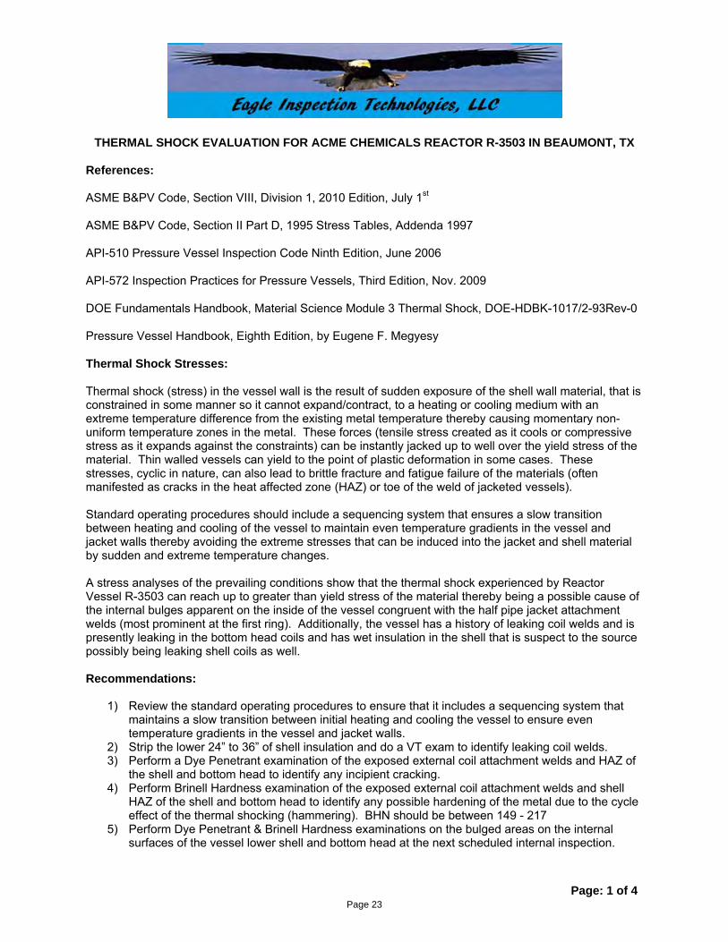
THERMAL SHOCK EVALUATION FOR ACME CHEMICALS REACTOR R-3503 IN BEAUMONT, TX
Page: 1 of 4
References:
ASME B&PV Code, Section VIII, Division 1, 2010 Edition, July 1st
ASME B&PV Code, Section II Part D, 1995 Stress Tables, Addenda 1997
API-510 Pressure Vessel Inspection Code Ninth Edition, June 2006
API-572 Inspection Practices for Pressure Vessels, Third Edition, Nov. 2009
DOE Fundamentals Handbook, Material Science Module 3 Thermal Shock, DOE-HDBK-1017/2-93Rev-0
Pressure Vessel Handbook, Eighth Edition, by Eugene F. Megyesy
Thermal Shock Stresses:
Thermal shock (stress) in the vessel wall is the result of sudden exposure of the shell wall material, that is constrained in some manner so it cannot expand/contract, to a heating or cooling medium with an extreme temperature difference from the existing metal temperature thereby causing momentary non-uniform temperature zones in the metal. These forces (tensile stress created as it cools or compressive stress as it expands against the constraints) can be instantly jacked up to well over the yield stress of the material. Thin walled vessels can yield to the point of plastic deformation in some cases. These stresses, cyclic in nature, can also lead to brittle fracture and fatigue failure of the materials (often manifested as cracks in the heat affected zone (HAZ) or toe of the weld of jacketed vessels). Standard operating procedures should include a sequencing system that ensures a slow transition between heating and cooling of the vessel to maintain even temperature gradients in the vessel and jacket walls thereby avoiding the extreme stresses that can be induced into the jacket and shell material by sudden and extreme temperature changes. A stress analyses of the prevailing conditions show that the thermal shock experienced by Reactor Vessel R-3503 can reach up to greater than yield stress of the material thereby being a possible cause of the internal bulges apparent on the inside of the vessel congruent with the half pipe jacket attachment welds (most prominent at the first ring). Additionally, the vessel has a history of leaking coil welds and is presently leaking in the bottom head coils and has wet insulation in the shell that is suspect to the source possibly being leaking shell coils as well. Recommendations:
1) Review the standard operating procedures to ensure that it includes a sequencing system that maintains a slow transition between initial heating and cooling the vessel to ensure even temperature gradients in the vessel and jacket walls.
2) Strip the lower 24” to 36” of shell insulation and do a VT exam to identify leaking coil welds. 3) Perform a Dye Penetrant examination of the exposed external coil attachment welds and HAZ of
the shell and bottom head to identify any incipient cracking. 4) Perform Brinell Hardness examination of the exposed external coil attachment welds and shell
HAZ of the shell and bottom head to identify any possible hardening of the metal due to the cycle effect of the thermal shocking (hammering). BHN should be between 149 - 217
5) Perform Dye Penetrant & Brinell Hardness examinations on the bulged areas on the internal surfaces of the vessel lower shell and bottom head at the next scheduled internal inspection.
Page 23

THERMAL SHOCK EVALUATION FOR ACME CHEMICALS REACTOR R-3503 IN BEAUMONT, TX
Page: 2 of 4
Thermal Shock Stress Analysis: R-3503 Material: 300 Series Stainless Steel, SA 240 316L Yield Stress: 25,000 psi Tensile Stress: 70,000 psi
Thermal Shock Stress Evaluation
E = MOE, psiα = COE, °F-1
Tmin = Operating temperature of cooling mediumTmax = Operating temperature of heating medium∆T = Temperature Diff., ºF (=Tmax-Tmin)S1 =Stress in compression of vessel wall, psi (= Eα∆T)
E α Tmin Tmax ∆T S1
26750000 0.0000091 50 350 300 73028PSI °F-1 ºF ºF ºF PSI
Hoop Stress (Operating Pressure) Evaluation
p = maximum pitch, in. (dist between stiffeners)P = max operating pressure on vessel wall, psiC = 2.1, Coeff. for welded stays for plates < 7/16 in. in thicknesst = thickness of the vessel part under consideration, inS2 = hoop stress in vessel wall, psi (= P/((t/p)^2C))
p P C t S2
3.5 140 2.1 0.25 13067in psi in ºF
Final Stress Analysis
S = total stress on vessel wall, psi (S1 + S2)Y = yield stress of material, psiRatio = S/Y Ratio's > 0.6 may experience chronic damage in the form of brittle fracture (cyclic effect).
Ratio's > 1.0 may experience acute damage in the form of brittle fracture, weld cracks, and deformation.
S Y Ratio
86094 25000 3.44
psi psi Overstress condition
(when area of interest is not slowly and evenly heated over sufficient period of time)
Page 24

THERMAL SHOCK EVALUATION FOR ACME CHEMICALS REACTOR R-3503 IN BEAUMONT, TX
Page: 3 of 4
Page 25

APPENDIX B
1) Component Thickness Measurements
2) Nozzle Thickness Measurements
Thickness Measurement Records
Report No.: 10003
Page 26

Inspection Data
Components with Vert. Axis: tml-1 N., tml-2 E., tml-3 S., tml-4 W. (Drawing N.)
Components with Horz. Axis: tml-1 Top, tml-2 Side, tml-3 Bttm., tml-4 Side (Clock Wise)
API-510 PRESSURE VESSEL COMPONENT THICKNESS RECORD
Report No
10003
Inspector
Jeff Walling
Client
ACME Chemical
Vessel
R-3503
Date
5/10/2010
Comp ID Location Service tml-1 tml-2 tml-3 tml-4 MinimumCML #
Top Head Crown Radius Product 0.616 0.603 0.603 0.587 0.587001
Vessel Shell Upper Shell Product 0.655 0.655 0.650 0.652 0.650002
Vessel Shell Mid Shell Product 0.654 0.656 0.663 0.643 0.643003
Vessel Shell Lower Shell Product 0.659 0.665 0.664 0.660 0.659004
Bttm Head Crown Radius Product 0.646 0.620 0.640 0.637 0.620005
Jacket Coil Shell Steam 0.107 0.106 0.106 0.108 0.106006
Jacket Coil Bttm Head Steam 0.106 0.105 0.107 0.104 0.104007
24" MW MW1 Manway 0.531 0.521 0.513 0.528 0.513008
20" MW N1 Agitator 0.542 0.538 0.539 0.529 0.529009
3" Nozzle N2 Blank 0.213 0.212 0.212 0.210 0.210010
2" Nozzle N3 GOAG 0.154 0.154 0.154 0.153 0.153011
2" Nozzle N4 Injection 0.153 0.155 0.153 0.155 0.153012
3" Nozzle N5 Reflux 0.213 0.213 0.214 0.213 0.213013
10" Nozzle N6 Reflux 0.395 0.396 0.396 0.399 0.395014
8" Nozzle N7 Vent 0.400 0.401 0.388 0.392 0.388015
1" Nozzle N8 Nitogen 0.110 0.106 0.106016
1" Nozzle N9 PSI Gage 0.110 0.107 0.107017
6" Boss N10 Site Glass018
6" Boss N11 Site Glass019
3" Nozzle N12 MEA 0.214 0.215 0.212 0.209 0.209020
2" Nozzle N13 NOAH 0.154 0.155 0.154 0.155 0.154021
2" Nozzle N14 T.I.022
Report No.: 10003
Page 27

Comp ID Location Service tml-1 tml-2 tml-3 tml-4 MinimumCML #
2" Nozzle N15 T.I.023
1.5" Nozzle N16 T.I.024
6" Boss N17 Cooling025
2" Nozzle N18 Recirc026
6" Boss N19 Cooling027
1" Nozzle N20 Injection028
Report No.: 10003
Page 28
APPENDIX C
1) Vessel Drawing
2) Shell Layout Drawing
Inspection Drawings
Report No.: 10003
Page 29

Page 30

Page 31
APPENDIX D
1) Pressure Vessel Inspection Checklist
Inspection Checklist
Report No.: 10003
Page 32

Company: ACME Chemical Vessel: R-3503 Report No.: 10003 Date: 5/10/2010
Inspector: Jeff WallingCert No.: 2782
API-510 PRESSURE VESSEL INSPECTION CHECKLIST
a. Xb. Xc. Xd. X
a. Xb. Xc. X
b.
c.
a.b.c.d.e.
a. Xb.c.d.e. Xf.g. X
a. Xb. Xc. Xd. Xe. Xf.g. Xh.
a. Xb. Xc. Xd. Xe. Xf. Xg. X
a. Xb. X
X Inlet: 6" Outlet: 6"d. Xe. X None Foundf. X 152psi@366degFg. X Ruprtur Disc - FIKE
a.b.
c.
1.1 Steel Members
Visually inspect for pitting, and corrosion.
Check fnd bolts secure with minimum thrd engagement.
Check for coating failures
Check attachment welds for cracking and corrosion.
1.3 Concrete Foundation Supports
Inspect for broken concrete, spalling and cracks.
Inspect for erosion under foundation.
Check for settlement around perimeter of tank.
1 FOUNDATION
1.4 Wooden Saddle Support
Check for degradaded members (split, broken, dry rotted et.).
Inspect for errosion and vegetation tank fnd.
Check for settlement around perimeter of tank.
1.2 Containment
Inspect the area for buildup of trash, vegetation and obstructions.
Inspect sump drain operation.
Check that runoff rainwater drains away from the tank.
Describe type of construction - Earthen, Concrete, Asphalt, Grav
Inspect condition of containment.
2.1 External Visual Inspection
2 SHELLS
Visually inspect shell surface for paint failures, pitting, corrosion, denting, out-of-round and part deformation.
Check for broken, unused insulation rod supports causing corrosion nodes.
Visually inspect weld joints for cracking, pitting, corrosion and signs of leaking (product residue).
Perform dye penetrant or magnetic particle tests if leaks or cracks are suspected.
Check for proper grounding
2.2 Internal Visual Inspection
Check atmospheric conditions, fill out and post safe entry permit form.
Appropriate and wear required PPE for safe entry.
Inspect shell surfaces for coating failures, pitting and corrosion.
Inspect baffle plate surfaces weld attachments for cracking, pitting, or corrosion. Check bolts are secure with minimum thread engagement.
Inspect agitator shaft and blade surfaces for cracking, pitting, corrosion. Check bolts are secure and have minimum thread engagement.
Inspect heating coils surfaces and weld attachments, for cracking, pitting, corrosion. Check bolts are secure with minimum thread engagemen
Inspect pressure containing weld joints for cracking, pitting, and corrosion.
Perform dye penetrant or magnetic particle tests if cracks are suspected.
3.1 Manways and Nozzles
3 SHELL APPURTENANCES
Inspect for cracks or signs of leakage on weld joints at nozzles, manways, and reinforcing plates.
Inspect for shell plate dimpling around nozzles, caused by excessive pipe deflection.
Inspect for flange leaks and leaks around bolting.
Check flange bolts are secure and have minimum thread engagement.
Inspect sealing of insulation around manways and nozzles.
Check for inadequate manway flange and cover thickness on mixer manways.
Check exposed flange and cover faces.
3.2 Relief Devices
Inspect for flange leaks and leaks around bolting.
Check flange bolts are secure and have minimum thread engagement.
Record inlet and outlet sizes sizes.
Check that relief system outlet discharges to safe location (outside of building).
Record certification date
Record pressure setting
Record type and ID
Inspect sample lines for function of valves and plugging of lines, including drain or return-to-tank line.
Check circulation pump for leaks and operating problems.
Test bracing and supports of sample system and equipment.
3.3 Shell-Mounted Sample Station
a.
c.
Clean angles and other components that form catch basins and check for degradation and corrosion..
Inspect nozzle penetration surfaces and welds for corrosion, cracking and deformation.
Page 1 of 3
Page 33

Company: ACME Chemical Vessel: R-3503 Report No.: 10003 Date: 5/10/2010
Inspector: Jeff WallingCert No.: 2782
API-510 PRESSURE VESSEL INSPECTION CHECKLIST
a. X
a. Xb. Xc. X
a.b.
c.d.
a.b.c.
a. Xb. Xc. Xd.e.f.g. Xh.
a. Xb. Xc. X
a.b.c.d.
a. Xb. X
Inspect condensate drain for presence of oil, indicating leakage.
3.4 Heater (Steam Coils)
Inspect for proper mounting flange and support.
3.5 Mixer/Agitator
Inspect for leakage.
Inspect condition of power lines and connections to mixer.
Inspect deck plate for corrosion-caused thinning or holes (not drain holes) and paint failure.
Inspect plate-to-frame weld for rust scale buildup.
Inspect grating for corrosion-caused thinning of bars and failure of welds.
Check grating tie down clips. Where grating has been retrofitted to replace plate, measure the rise of the step below and above the grating surface and with other risers on the stairway.
3.6 Deck Plate and Grating
Inspect stairway stringers, rungs and treads for corrosion, paint failure and weld failure.
Inspect stairway supports to shell welds and reinforcing pads.
Inspect steel support attachment to concrete base for corrosion.
3.7 Stairway Stringers/Rungs/Treads
Identify type of jacket (half pipe, cylindrical, dimpled and spot welded, etc.)
Measure and record pitch distances.
Visually inspect shell surface for paint failures, pitting, corrosion, denting, out-of-round and part deformation.
4 VESSEL JACKET
Clean angle support rings and inspect for corrosion and thinning on plate, annular space and welds.
Inspect the shell-to-foundation seal or barrier.
Check for broken, unused insulation rod supports causing corrosion nodes.
Visually inspect for weld joints for cracking, pitting, corrosion and signs of leaking (product residue).
Perform dye penetrant or magnetic particle test if leaks or cracks are suspected.
Check for holes, missing portions, deterioration due to corrosion or abuse.
Check for sufficient sealing, especially around vessel appurtenances.
Check for wetness
5 INSULATION
4.1 Jacket Shell
5.1 Visual Inspection
Check that indicators are securely attached and operating properly.
Check that indicators are in accessible locations and readable.
Check that indicators have current calibration date.
6 PRESSURE /TEMPERATURE INDICATORS
6.1 Physical and Operating Conditions
Check for any damage, and corrosion build up.
Check that ASME plate is securely attached
Check that ASME plate is in accessible location and readable.
7 ASME/NAME PLATE DATA
7.1 Physical Condition
Page 2 of 3
Page 34
Company: ACME Chemical Vessel: R-3503 Report No.: 10003 Date: 5/10/2010
Inspector: Jeff WallingCert No.: 2782
API-510 PRESSURE VESSEL INSPECTION CHECKLIST
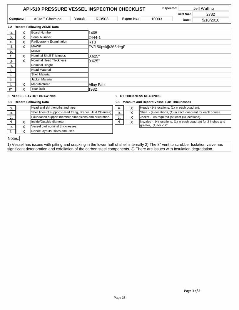
a. X 1405b. X 2444-1c. X RT3d. X FV/[email protected]. X 0.625"g. X 0.625"h.i.j.
k.l. X Alloy Fab
m. X 1982
Board Number
Serial Number
7.2 Record Following ASME Data
Radiography Examination
MAWP
MDMT
Nominal Shell Thickness
Nominal Head Thickness
Nominal Hieght
Head Material
Shell Material
Jacket Material
Manufacturer
Year Built
a.b.c.d. Xe. Xf. X
Head and skirt lengths and type.
8 VESSEL LAYOUT DRAWINGS
8.1 Record Following Data
Shell lines of support (Head Tang, Braces, Jckt Closures)
Foundation support member dimensions and orientation.
Inside/Outside diameter.
Vessel part nominal thicknesses.
Nozzle layouts, sizes and uses.
a. Xb. Xc. Xd. X
9 UT THICKNESS READINGS
9.1 Measure and Record Vessel Part Thicknesses
Shell - (4) locations, (1) in each quadrant for each course.
Jacket - As required (at least (4) locations).
Nozzles - (4) locations, (1) in each quadrant for 2 inches and greater, (1) for < 2"
Heads - (4) locations, (1) in each quadrant.
Notes:
1) Vessel has issues with pitting and cracking in the lower half of shell internally 2) The 8" vent to scrubber Isolation valve has significant deterioration and exfoliation of the carbon steel components. 3) There are issues with Insulation degradation.
Page 3 of 3
Page 35
APPENDIX E
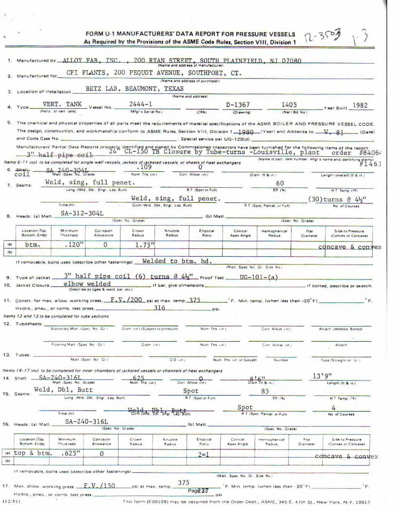
1) U1 Mfg Data Sheet
Manufacturers Data Sheets
Report No.: 10003
Page 36
Page 37
Page 38
Page 39

APPENDIX F
Inspection Photographs
Report No.: 10003
Page 40
ACME CHEMICALS. - R-3503 REPORT – 10003-001 INSPECTION PHOTOGRAPHS
Reactor vessel R-3503 top head
ASME Nameplate.
Page 41

ACME CHEMICALS. - R-3503 REPORT – 10003-001 INSPECTION PHOTOGRAPHS
Rupture Disc and corroded iso vent valve
Corroded iso vent valve
Page 42
ACME CHEMICALS. - R-3503 REPORT – 10003-001 INSPECTION PHOTOGRAPHS
1” Plug leaking condensed vent gases onto iso vent valve
Page 43
ACME CHEMICALS. - R-3503 REPORT – 10003-001 INSPECTION PHOTOGRAPHS
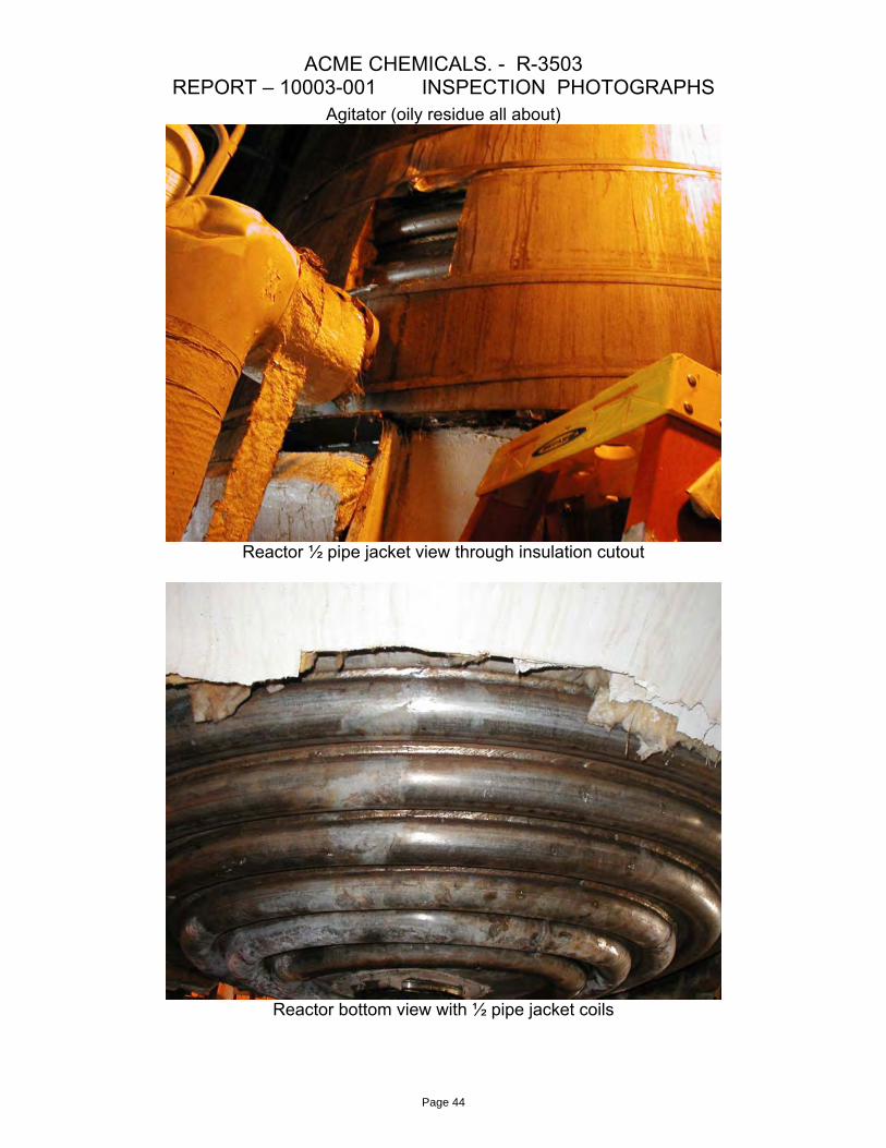
Agitator (oily residue all about)
Reactor ½ pipe jacket view through insulation cutout
Reactor bottom view with ½ pipe jacket coils
Page 44
ACME CHEMICALS. - R-3503 REPORT – 10003-001 INSPECTION PHOTOGRAPHS
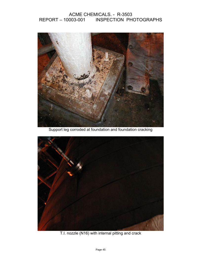
Support leg corroded at foundation and foundation cracking
T.I. nozzle (N16) with internal pitting and crack
Page 45
ACME CHEMICALS. - R-3503 REPORT – 10003-001 INSPECTION PHOTOGRAPHS
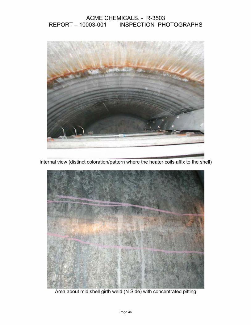
Internal view (distinct coloration/pattern where the heater coils affix to the shell)
Area about mid shell girth weld (N Side) with concentrated pitting
Page 46

ACME CHEMICALS. - R-3503 REPORT – 10003-001 INSPECTION PHOTOGRAPHS
Stress cracks at the baffle attachment weld to shell
Cracks in nozzle N16
Page 47
ACME CHEMICALS. - R-3503 REPORT – 10003-001 INSPECTION PHOTOGRAPHS
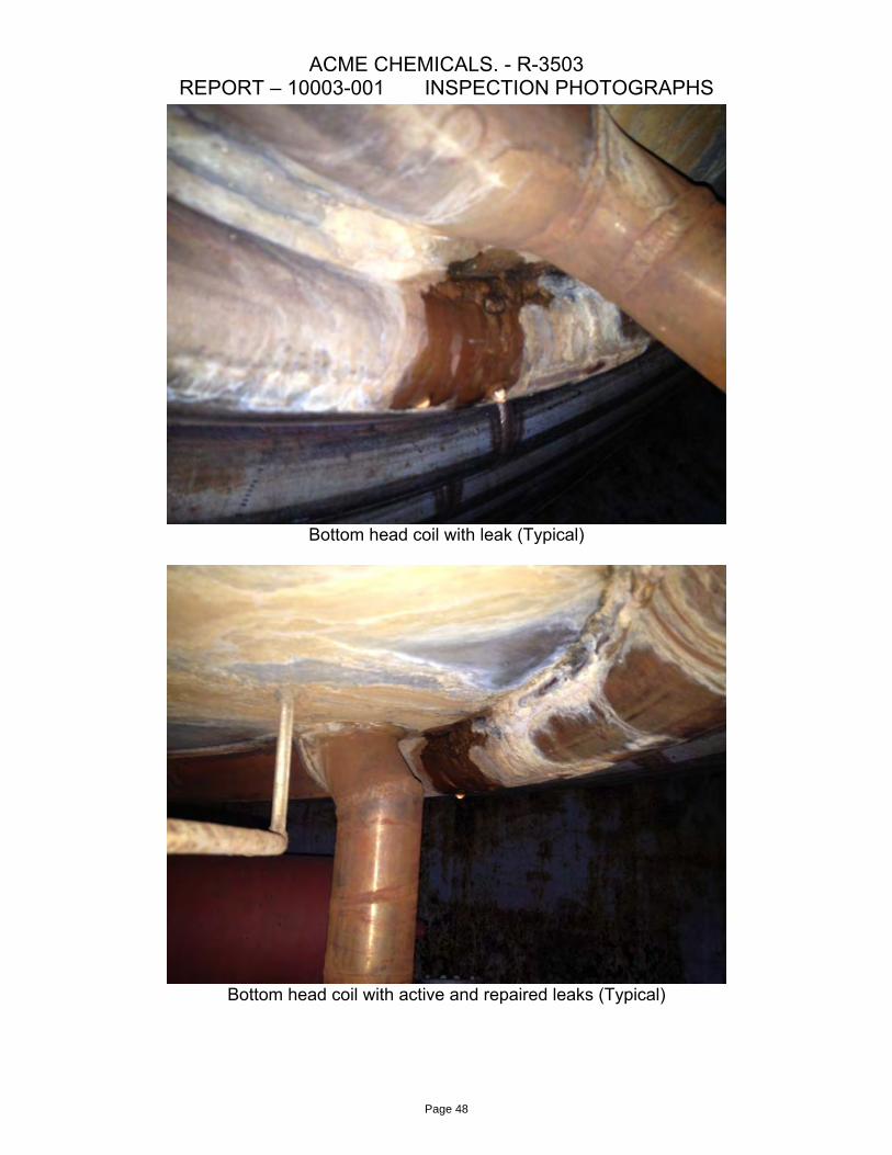
Bottom head coil with leak (Typical)
Bottom head coil with active and repaired leaks (Typical)
Page 48
ACME CHEMICALS. - R-3503 REPORT – 10003-001 INSPECTION PHOTOGRAPHS
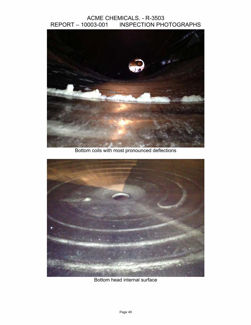
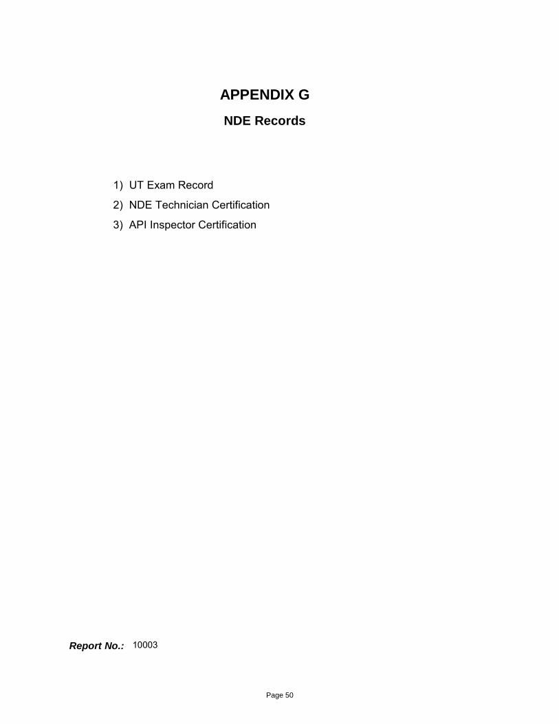
Bottom coils with most pronounced deflections
Bottom head internal surface
Page 49
APPENDIX G
1) UT Exam Record
2) NDE Technician Certification
3) API Inspector Certification
NDE Records
Report No.: 10003
Page 50
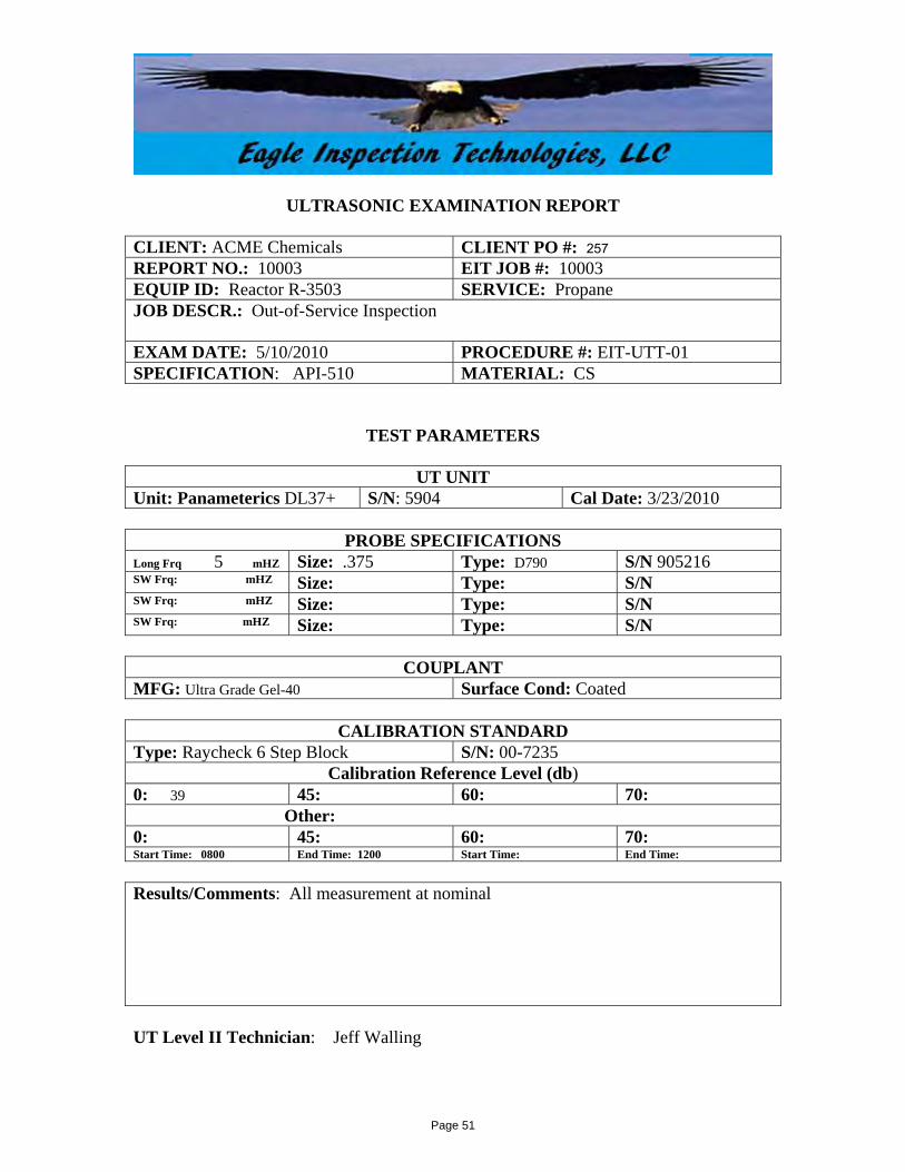
ULTRASONIC EXAMINATION REPORT CLIENT: ACME Chemicals CLIENT PO #: 257REPORT NO.: 10003 EIT JOB #: 10003 EQUIP ID: Reactor R-3503 SERVICE: Propane JOB DESCR.: Out-of-Service Inspection EXAM DATE: 5/10/2010 PROCEDURE #: EIT-UTT-01 SPECIFICATION: API-510 MATERIAL: CS
TEST PARAMETERS
UT UNIT Unit: Panameterics DL37+ S/N: 5904 Cal Date: 3/23/2010
PROBE SPECIFICATIONS Long Frq 5 mHZ Size: .375 Type: D790 S/N 905216 SW Frq: mHZ Size: Type: S/N SW Frq: mHZ Size: Type: S/N SW Frq: mHZ Size: Type: S/N
COUPLANT MFG: Ultra Grade Gel-40 Surface Cond: Coated
CALIBRATION STANDARD Type: Raycheck 6 Step Block S/N: 00-7235
Calibration Reference Level (db) 0: 39 45: 60: 70: Other: 0: 45: 60: 70: Start Time: 0800 End Time: 1200 Start Time: End Time:
Results/Comments: All measurement at nominal UT Level II Technician: Jeff Walling
Page 51

NAME:
METHOD LEVEL DATE EXAMINER GENERAL SPECIFIC PRACTICAL COMPOSITEUTT II 4/9/2010 Joe Monroe 86% 100% 95% 94% 4/9/2015PT II 9/3/2010 Wayne Bailey 93% 95% 91% 93% 9/3/2015MT II 9/3/2010 Wayne Bailey 93% 95% 85% 91% 9/3/2015
MFE II 1/21/2011 Brian Rotto 90% 85% 89% 88% 1/21/2016
FROM TO6/2009 9/2013
1/19/2004 11/20/20099/1/1998 4/15/2003
9/16/1995 9/1/1998
EAGLE I. TECHNOLOGIES Jeffrey WallingNDT CERTIFICATION / QUALIFICATION RECORD Employee ID Number: 3965
NDT CERTIFICATIONS EXAM SCORES EXPIRATION DATE RESTRICTIONS
thickness onlyNoneNoneNone
PREVIOUS EMPLOYER NDT CERTIFICATIONSCOMPANY NAME/ADDRESS NDT METHODS & HIGHEST LEVEL ATTAINED
Westech Inspection Level II UT thickness limitedBP/GIANT Level II UTT/MT/PT/LT
MATIS Level II UTT/MT/PT
CAPE Level II UTT/MT/PT/MFE
EYE EXAMINATION EDUCATION AND TRAININGDATE TYPE TESTED BY PASS / FAIL ORG DATE LENGTH
10/22/2012 Far Amer. Best Pass MATIS 12/16/1997 12 hours10/22/2012 Near Amer. Best Pass MATIS 12/16/1997 12 hours10/22/2012 Color Contrast Amer. Best Pass Eastern NDT 4/9/2010 24 hours
WCFS 8/25/2010 20 hoursWCFS 8/27/2010 12 hoursCAPE 1/21/2011 8 hours
CERT EXP DATE CERT EXP DATEAPI 653 4/30/2014 PD DEP 1/10/2016API 510 6/30/2014 NB Comm. 2014API 570 6/30/2014 VA-B&PV Com 2013 HOURS
STI 9/18/2017 MET.AS 2012
-ASNT
CERT No.
10/22/2012DATE
INSTRUCTOR SUBJECTDavid Spooner Level II UTT
Joe Monroe Level II UTTDavid Spooner Level II PT
refer to employee eye exam cert (CAPE-FRM-101) Stan Meyer Level II MT
OTHER NOTABLE CERTIFICATIONS OR QUALIFICATIONS
Stan Meyer Level II PTBrian Rotto Level II MFE
TRAINEE / LEVEL I NDT HOURS (IF APPLICABLE)METHOD EMPLOYER TOTAL DATE
Jeff Walling
This NDT Qualification record is in accordance with EIT-WP-01 and SNT-TC-1A (2006). All historical information supplied for this document is true and accurate to the best of my knowledge.SIGNATURE
EIT Certification Record Form: CAPE-FRM-102
NDE PROGRAM MANAGER
Page 52

Page 53
APPENDIX H
ASME B&PV Code, Section VIII, Division 1, 2010 Edition, July 1st
ASME B&PV Code, Section II Part D, 1995 Stress Tables, Addenda 1997
API-510 Pressure Vessel Inspection Code Ninth Edition, June 2006
API-572 Inspection Practices for Pressure Vessels, Third Edition, Nov. 2009
DOE Fundamentals Handbook, Material Science Module 3 Thermal Shock, DOE-HDBK-1017/2-93Rev-0
Pressure Vessel Handbook, Eighth Edition, by Eugene F. Megyesy
ASNT SNT-TC-1A 2011 Edition
References
Report No.: 10003
Page 54