Embed Size (px)
Citation preview
M i n i s t è r e d e l ’ E c o l o g i e , d u D é v e l o p p e m e n t d u r a b l e e t d e l ’ E n e r g i e
Bureau d’Enquêtes et d’Analysespour la sécurité de l ’aviation civile
Report
Accident on 25 April 2010at Nadi (Fiji)to the Beechcraft B200registered F-OIANoperated by Air Alizé
Published August 2014

F-OIAN - 25 April 20102
The BEA is the French Civil Aviation Safety Investigation Authority. Its investigations are conducted with the sole objective of improving aviation safety and are not intended to apportion blame or liability.
BEA investigations are independent, separate and conducted without prejudice to any judicial or administrative action that may be taken to determine blame or liability.
SPECIAL FOREWORD TO ENGLISH EDITION
This is a courtesy translation by the BEA of the Final Report on the Safety Investigation. As accurate as the translation may be, the original text in French is the work of reference.
Safety Investigations

F-OIAN - 25 April 20103
Table of Contents
SAFETY INVESTIGATIONS 2
GLOSSARY 5
SYNOPSIS 6
ORGANISATION OF THE INVESTIGATION 7
1 - FACTUAL INFORMATION 8
1.1 History of the Flight 8
1.2 Killed and Injured 8
1.3 Damage to the Aircraft 8
1.4 Other Damage 9
1.5 Personnel Information 91.5.1 Captain 91.5.2 Co-pilot 9
1.6 Aircraft Information 10
1.6.1 Airframe 101.6.2 Engines 101.6.3 Maintenance 101.6.4 Weight and balance 101.6.5 Description of the electrical system 101.6.6 Landing gear 11
1.7 Meteorological Conditions 15
1.7.1 General situation 151.7.2 Meteorological conditions at Nadi during the landing 15
1.8 Aids to Navigation 15
1.9 Telecommunications 15
1.10 Aerodrome Information 15
1.11 Flight Recorders 15
1.12 Wreckage and Impact Information 151.12.1 The site 151.12.2 Airframe and engines 161.12.3 Electrical system 17
1.13 Medical and Pathological Information 18
1.14 Fire 18
1.15 Survival Aspects 18

F-OIAN - 25 April 20104
1.16 Tests and Research 181.16.1 Investigation of the electrical failure 181.16.2 Landing gear control handle 181.16.3 Diodes fitted to electric circuit No. 2 181.16.4 Hypothesis about overvoltage in the electrical system 18
1.17 Information on Air Alizé 19
1.18 Additional Information 19
1.18.1 Accounts from the flight crew 191.18.2 Anomalies detected on the hydraulic power packs 201.18.3 Emergency and abnormal situations 201.18.4 Similar events 21
2 - ANALYSIS 23
2.1 Failure of Electric Circuit N° 2 23
2.2 Management of the Electrical Failure 23
3 - CONCLUSION 25
3.1 Findings 25
3.2 Causes of the Accident 25
LIST OF APPENDICES 26
F-OIAN - 25 April 20105
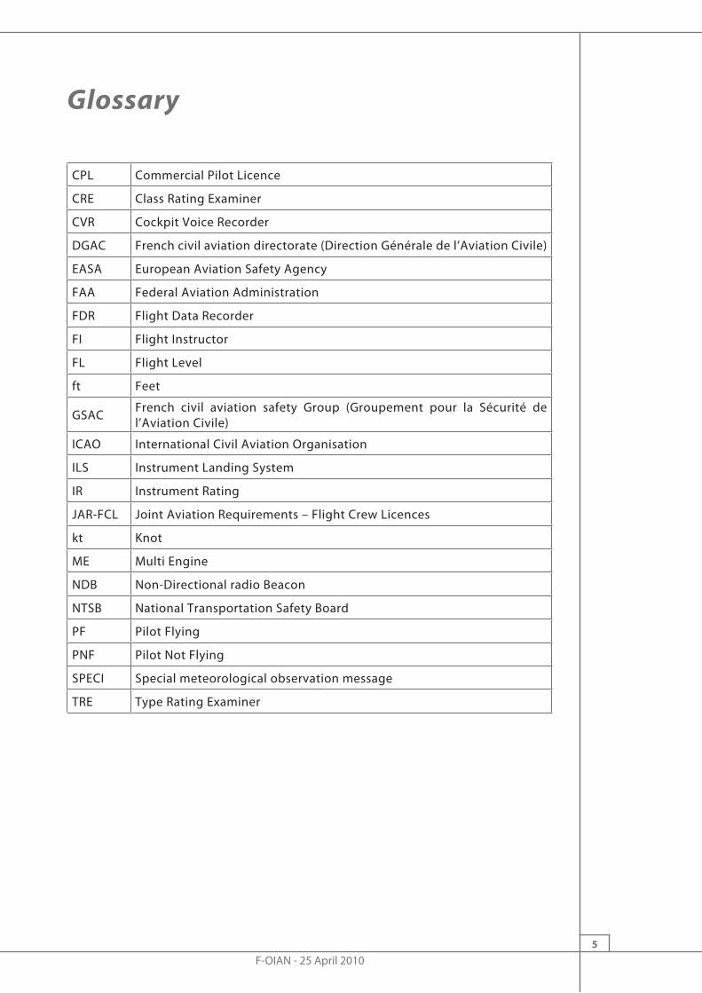
Glossary
CPL Commercial Pilot Licence
CRE Class Rating Examiner
CVR Cockpit Voice Recorder
DGAC French civil aviation directorate (Direction Générale de l’Aviation Civile)
EASA European Aviation Safety Agency
FAA Federal Aviation Administration
FDR Flight Data Recorder
FI Flight Instructor
FL Flight Level
ft Feet
GSAC French civil aviation safety Group (Groupement pour la Sécurité de l’Aviation Civile)
ICAO International Civil Aviation Organisation
ILS Instrument Landing System
IR Instrument Rating
JAR-FCL Joint Aviation Requirements – Flight Crew Licences
kt Knot
ME Multi Engine
NDB Non-Directional radio Beacon
NTSB National Transportation Safety Board
PF Pilot Flying
PNF Pilot Not Flying
SPECI Special meteorological observation message
TRE Type Rating Examiner

F-OIAN - 25 April 20106
Synopsis
f-an100424.en
Electrical failure during approach, landing with gear retracted, lateral runway excursion
Aircraft Beechcraft 200 registered F-OIANDate and time 25 April 2010 at 14h01(1)
Operator Air AlizéPlace Nadi AD (Fiji)Type of flight Positioning flight ahead of a medical evacuationPersons on board 2 flight crew, 2 passengersConsequences and damage Aircraft damaged
(1)All times in this report are UTC, except where otherwise specified. Twelve hours should be added to obtain the time in Fiji on the day of the event.
SUMMARY
During an ILS approach at night to runway 2 at Nadi aerodrome (Fiji), the n°2 electrical system failed. A little later, during final approach, the aural warning for non-extension of landing gear sounded. The crew decided to continue the approach. On landing, the aeroplane exited the runway to the right and came to a stop leaning on the fuselage. Examination of the aeroplane showed that the landing gear was retracted with the landing gear doors open.
The landing on the fuselage resulted from an incomplete analysis by the crew of the consequences of the electrical failure and the warning that triggered during the final approach.
CONSEQUENCES
Injuries Equipment
Fatal Serious Light/None
Crew - - 2
DamagedPassengers - - 2
Others - - -

F-OIAN - 25 April 20107
ORGANISATION OF THE INVESTIGATION
At the request of the Fiji Islands civil aviation authorities, the investigation was completely delegated to the BEA. A field investigator from New Caledonia went to Nadi to undertake the initial stages of the investigation, in coordination with the Fiji civil aviation authorities.
The NTSB (United States), as State of Manufacture of the aeroplane, appointed an accredited representative.
F-OIAN - 25 April 20108
1 - FACTUAL INFORMATION
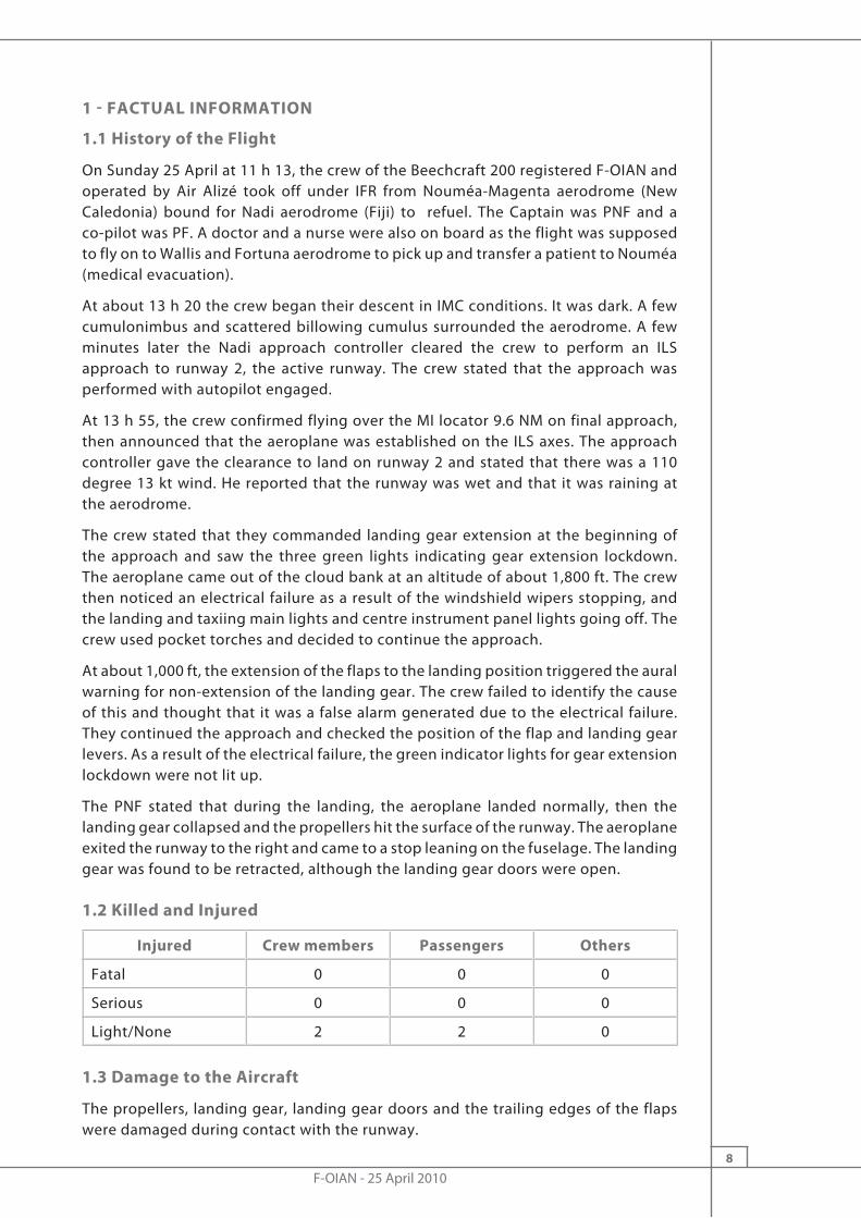
1.1 History of the Flight
On Sunday 25 April at 11 h 13, the crew of the Beechcraft 200 registered F-OIAN and operated by Air Alizé took off under IFR from Nouméa-Magenta aerodrome (New Caledonia) bound for Nadi aerodrome (Fiji) to refuel. The Captain was PNF and a co-pilot was PF. A doctor and a nurse were also on board as the flight was supposed to fly on to Wallis and Fortuna aerodrome to pick up and transfer a patient to Nouméa (medical evacuation).
At about 13 h 20 the crew began their descent in IMC conditions. It was dark. A few cumulonimbus and scattered billowing cumulus surrounded the aerodrome. A few minutes later the Nadi approach controller cleared the crew to perform an ILS approach to runway 2, the active runway. The crew stated that the approach was performed with autopilot engaged.
At 13 h 55, the crew confirmed flying over the MI locator 9.6 NM on final approach, then announced that the aeroplane was established on the ILS axes. The approach controller gave the clearance to land on runway 2 and stated that there was a 110 degree 13 kt wind. He reported that the runway was wet and that it was raining at the aerodrome.
The crew stated that they commanded landing gear extension at the beginning of the approach and saw the three green lights indicating gear extension lockdown. The aeroplane came out of the cloud bank at an altitude of about 1,800 ft. The crew then noticed an electrical failure as a result of the windshield wipers stopping, and the landing and taxiing main lights and centre instrument panel lights going off. The crew used pocket torches and decided to continue the approach.
At about 1,000 ft, the extension of the flaps to the landing position triggered the aural warning for non-extension of the landing gear. The crew failed to identify the cause of this and thought that it was a false alarm generated due to the electrical failure. They continued the approach and checked the position of the flap and landing gear levers. As a result of the electrical failure, the green indicator lights for gear extension lockdown were not lit up.
The PNF stated that during the landing, the aeroplane landed normally, then the landing gear collapsed and the propellers hit the surface of the runway. The aeroplane exited the runway to the right and came to a stop leaning on the fuselage. The landing gear was found to be retracted, although the landing gear doors were open.
1.2 Killed and Injured
Injured Crew members Passengers Others
Fatal 0 0 0
Serious 0 0 0
Light/None 2 2 0
1.3 Damage to the Aircraft
The propellers, landing gear, landing gear doors and the trailing edges of the flaps were damaged during contact with the runway.
F-OIAN - 25 April 20109
1.4 Other Damage
The propeller blades left marks on the surface of the runway and a runway perimeter light (the 25th on the right, starting from the approach end of runway 2) was destroyed.
1.5 Personnel Information
1.5.1 Captain
Male, aged 60
� Commercial pilot’s licence CPL (A) dated 29 July 1974, issued by France in accordance with JAR-FCL1 requirements
� Multi-engine instrument rating IR/ME (A) valid until 30 April 2011
� Beechcraft Be90/99/10/200 type rating valid until 30 April 2011
� Class rating examiner authorisation CRE (A) valid until 31 July 2012
� Flight instructor rating FI (A) valid until 30 September 2011
� Medical certificate, class 1, dated 4 March 2010 valid until 30 September 2010
� Experience:
� 5,527 flying hours, of which 1,739 hours on type � 63 hours in the previous three months, of which 50 on type � 34 hours in the previous thirty days, of which 28 on type
The Captain was recruited by Air Alizé in October 2006.
1.5.2 Co-pilot
Male, aged 54
� Commercial pilot’s licence CPL (A) dated 7 April 1989 issued by France in accordance with JAR-FCL1 requirements
� Multi-engine instrument rating IR/ME (A) valid until 30 September 2010
� Beechcraft Be90/99/10/200 type rating valid until 30 September 2010
� Helicopters: Valid commercial pilot’s licence CPL (H), flight instructor rating FI (H) and type rating examiner authorisation TRE (H)
� Medical certificate, class 1, dated 19 November 2009 valid until 31 May 2010
� Aeroplane experience:
� 1,135 flying hours, of which 402 hours on type � 28 hours in the previous three months, all on type � 13 hours in the previous thirty days, all on type
The co-pilot was employed by Air Alizé and also worked as a helicopter pilot for another operator (Hélicocéan).

F-OIAN - 25 April 201010
1.6 Aircraft Information
1.6.1 Airframe
The Beechcraft B200 is a twin-turboprop, low-wing aeroplane certified for single-pilot operation. The maximum approved passenger seating capacity is 9(2).
Manufacturer Beech Aircraft Corporation
Type Beech B200
Serial number BB-1220
Registration F-OIAN
Entry into service July 2005
Certificate of airworthiness No. 251486 dated 6 October 2009 issued by the DGAC
Airworthiness review certificate No. 2514861271193 dated 24 September 2009 issued by the DGAC and valid for one year
Utilisation as of 25 April 2010 8,498 flying hours
1.6.2 Engines
Manufacturer: Pratt & Whitney
Type: PT6A-42
Engine No. 1 Engine No. 2
Total running time 1,486 hours 8,327 hours
1.6.3 Maintenance
The aeroplane had been maintained by the LOCAVIA Part 145-approved integrated workshop in accordance with the approved maintenance manual. Its maintenance checks were up to date.
1.6.4 Weight and balance
The maximum takeoff weight (MTOW) for the Beechcraft 200 is 5,670 kg.
The aeroplane was within the weight and balance limits.
1.6.5 Description of the electrical system
Two electrical generators (left and right) and a battery supply electrical power to two main bus bars that are connected. Four independent secondary bus bars (dual-fed sub-bus) are linked to each of the main bus-bars through a series connection made up of a 50 A breaker and a 70 A diode.
In case of breaker tripping or the failure of a diode, the link with the main bus-bar is cut off. The secondary circuit remains powered by the other main bus-bar. When both of the diodes and the two breakers fail, the secondary circuit is isolated and no longer supplies the equipment associated with this circuit.
(2)Reference: EASA Type Certificate Data Sheet (EASA-TCDS IM A.277, Issue 03, 25 August 2011).
F-OIAN - 25 April 201011
The circuit-breaker panels located on the left and right sides of the cockpit allow the crew to know if a breaker has been tripped. However, the diodes are installed under the cabin floor and are not accessible to crews. There is no display in the cockpit to indicate the failure of one or more of the diodes.
Secondary circuit n°2 supplies the following equipment:
� The landing gear position lights; � The windscreen wipers; � The lighting for the centre console, the overhead panel and the lower instrument
panel; � The lighting system for the engine and avionics system instruments; � The RH engine control instruments (oil pressure, oil temperature, flowmeter); � The landing gear control; � The right side landing lights; � The identification lights; � The navigation lights; � The taxiing lights.
According to the aeroplane’s flight manual, the abnormal procedures associated with the electrical system are as follows:
� Electrical generator inoperative (amber light lit up L (R) DC GEN); � Excessive charge rate on the battery (amber BATTERY CHG light on); � Indication of excessive electrical load; � Breaker tripped; � Power supply circuit breaker (bus feeder) tripped.
1.6.6 Landing gear
1.6.6.1 Description of landing gear
F-OIAN is equipped with tricycle landing gear that is controlled electrically and manoeuvred hydraulically.
The three landing gears (nose and main) are located in compartments closed by two lateral doors when the landing gear is retracted. The movement of the doors is in synch with the movement of the landing gear.
Each landing gear has a hydraulic actuator.
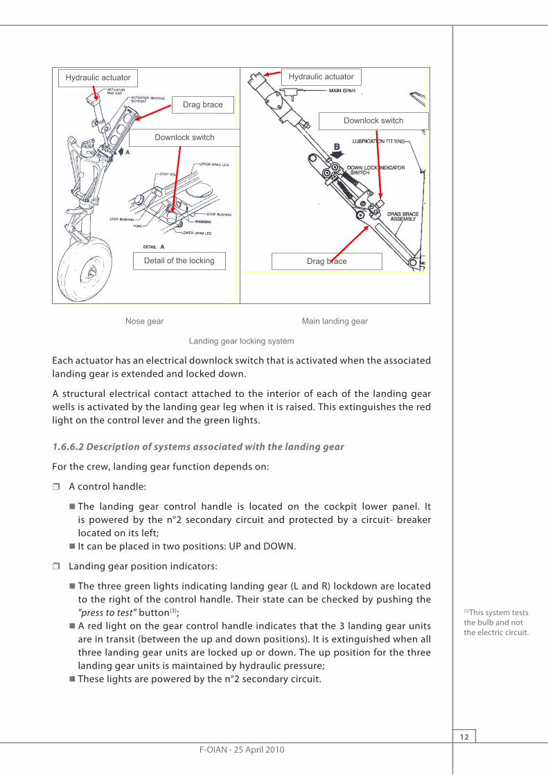
The nose gear is locked down both by a mechanical lock inside the hydraulic actuator and by locking a drag brace. The main landing gear is locked down by a mechanical catch installed on the drag brace, which is itself activated by the hydraulic actuator.
F-OIAN - 25 April 201012
Drag brace
Detail of the locking
Downlock switch
Hydraulic actuator Hydraulic actuator
Downlock switch
Drag brace
Nose gear Main landing gear
Landing gear locking system
Each actuator has an electrical downlock switch that is activated when the associated landing gear is extended and locked down.
A structural electrical contact attached to the interior of each of the landing gear wells is activated by the landing gear leg when it is raised. This extinguishes the red light on the control lever and the green lights.
1.6.6.2 Description of systems associated with the landing gear
For the crew, landing gear function depends on:
� A control handle:
� The landing gear control handle is located on the cockpit lower panel. It is powered by the n°2 secondary circuit and protected by a circuit- breaker located on its left;
� It can be placed in two positions: UP and DOWN.
� Landing gear position indicators:
� The three green lights indicating landing gear (L and R) lockdown are located to the right of the control handle. Their state can be checked by pushing the "press to test" button(3);
� A red light on the gear control handle indicates that the 3 landing gear units are in transit (between the up and down positions). It is extinguished when all three landing gear units are locked up or down. The up position for the three landing gear units is maintained by hydraulic pressure;
� These lights are powered by the n°2 secondary circuit.
(3)This system tests the bulb and not the electric circuit.

F-OIAN - 25 April 201013
� A warning system:
�When the landing gear have not extended or are not locked, an aural warning, powered by the n°2 secondary circuit and protected by a 5 A circuit-breaker, is triggered in the following circumstances:- When the thrust of at least one of the engines is less than 81% N1,- or if the flaps are in landing position.
� In either case, the control handle red light also comes on.
These systems are independent of each other and a failure of one of them does not affect the functioning of the others.
1.6.6.3 Hydraulic system
The hydraulic pressure used for normal operation of the landing gear is supplied by a hydraulic power pack. A manual pump, whose lever is located in the cockpit between the control pedestal and the Captain’s seat, allows pressure to be supplied to extend the landing gear in an emergency.
The hydraulic power pack consists mainly of:
� A hydraulic reservoir;
� A hydraulic power pack that includes:
� An electric pump protection system; � An electric pump that supplies the hydraulic pressure required to extend and retract the landing gear. It is supplied with 28 V DC by the right main busbar through a power relay. It is protected by a 60A circuit breaker located under the cabin floor. The electric pump is no longer powered electrically:- when the three landing gear units are in the up position;- when the three landing gear units are extended and locked down;- when the protection circuit is operating.
� A pressurised reservoir supplies the electric pump and the hand pump; � A pressure contact that allows the electric pump to be powered through power relays in relation to hydraulic system pressure. The electric pump is thus powered electrically to maintain pressure of between 2,400 and 2,800 psi;
� A low hydraulic fluid level detector; � A valve activated by two solenoids (one for gear retraction and the other for extension). This valve makes it possible to supply the hydraulic fluid under pressure to the landing gear actuators. It also makes it possible for the hydraulic fluid coming from the actuators to return to the reservoir. When the extension (or retraction) solenoid is powered electrically, the valve allows the hydraulic fluid coming from the electric pump to pass into the exit chamber of the landing gear actuators. The choice of solenoid is determined by the position of the landing gear control handle;
� An accumulator that allows pressure in the hydraulic circuit to be maintained when the landing gear is retracted and to prevent the electric pump from operating too frequently.

F-OIAN - 25 April 201014
1.6.6.4 Electrical operation during landing gear manoeuvre
When the landing gear control lever is placed in extended position:
� The electric pump valve solenoid used for extending the landing gear is powered up. The hydraulic fluid coming under pressure from the electric pump is sent into the exit chamber of the landing gear actuators;
� The electric pump power relay is energized;
� The valve’s electric locking contact lights the associated green light when a landing gear is extended and locked down;
� When all three landing gear units are extended and locked down:
� The electrical pump and the solenoid used for extending the landing gear are no longer powered electrically,
� The red light on the control handle is no longer lit up.
When the landing gear control lever is placed in retracted position:
� The electric pump valve solenoid used for retracting the landing gear is powered up. The hydraulic fluid coming under pressure from the electric pump is sent into the entry chamber of the landing gear actuators;
� The electric pump power relay is energized to maintain pressure at between 2,400 and 2,800 psi, which enables the landing gear to be maintained in the retracted position (the accumulator also makes it possible to maintain the pressure in the circuit and prevents the electric pump from operating too frequently);
� The red light on the control handle is switched off as soon as the structure contacts detect that the landing gear units are in the stowed position.
1.6.6.5 Hydraulic power pack maintenance
Based on information provided by the manufacturer(4), it may be stated that:
� One cycle(5) of the hydraulic power pack is a normal operation which occurs once or twice as the aeroplane climbs towards cruise altitude;
� The hydraulic power pack may perform a cycle occasionally if the pressure drops or there is a change in temperature;
� The time between any two hydraulic power pack re-pressurisation cycles is approximately 15 to 30 minutes;
� An interval between cycles of less than 15 minutes requires a complete inspection of the system (hydraulic power pack, actuators, hand pump, control valve and accumulator) to check for any leaks or by-passes.
An operational test of the hydraulic power pack must be performed during every 200 and 600-hour maintenance inspection. If an anomaly is detected the power pack must be replaced.
Other than during these tests performed as part of maintenance inspections, the hydraulic power pack must also be replaced if an anomaly is discovered. Beechcraft do not specify any operating limits for the hydraulic power packs. The maintenance manual indicates that after each cycle of operation, the cooling time is one minute before the next use. An additional five-minute wait is required after five cycles.
(4)Service Information 2006-02 from the manufacturer, page 8/18.(5)Operation of the hydraulic power to re-pressurize the hydraulic circuit.
F-OIAN - 25 April 201015
1.7 Meteorological Conditions
1.7.1 General situation
An active convergence line was crossing the north of the Fiji islands with cumulonimbus and squalls.
From 12 h 15 onwards, cumulonimbus at Nadi aerodrome produced storms with rain, reducing visibility at times to 3,000 m. This cloud had moved on by 17 h 00.
1.7.2 Meteorological conditions at Nadi during the landing
SPECI issued at 14 h 00:
� SPECI NFFN 251400Z 13013KT 10KM TSRA FEW018CB SCT028TCU OVC100 23/22 Q1006 TEMPO 3000 TSRA RMK RR 7.1(6)
1.8 Aids to Navigation
The ILS 02 approach procedure for Nadi relies on the following radio navigation equipment:
� Two locators (MI at a frequency of 364 kHz and Al, an outer marker, at a frequency of 385 kHz);
� An ILS (INN at a frequency of 109.9 MHz); the beam of the localiser is aligned with the runway; the glide slope is three degrees.
1.9 Telecommunications
The transcript of the communications between the crew of F-OIAN and the Nadi approach controller is in Appendix 2. It shows that the crew made no mention of a technical problem during the approach and landing.
1.10 Aerodrome Information
The characteristics and configuration of the aerodrome had no bearing on the accident.
The ILS approach procedure for runway 2 is provided in appendix 3.
1.11 Flight Recorders
No flight data (FDR) or voice (CVR) recorder is required by the regulations for this type of aeroplane. The aeroplane was not equipped with these recorders.
1.12 Wreckage and Impact Information
1.12.1 The site
Marks made by the propeller blades were visible on the runway, covering a distance of about 200 metres, starting 1,020 metres from the approach end of runway 2. Additional marks, spaced further apart, were visible leading up to the aeroplane. The engines powered the propellers equally almost until the aeroplane came to a stop alongside the runway.
(6)RR 7.1: 7.1 mm of rain in the previous hour.

F-OIAN - 25 April 201016
The aeroplane came to rest on a flat, grassy surface, alongside runway 2, approximately 1,560 metres from the approach end of the runway. It was supported by the lower part of the fuselage, and the direction of its longitudinal axis was 055°.
1.12.2 Airframe and engines
There were visible signs of an impact on the composite material radome that was more likely to be due to an impact with a foreign body, probably as the aeroplane skidded with the landing gear not extended, rather than to a lightning strike.
The nose gear doors were in an almost completely open position. The main gear’s doors had been scraped as a result of the sustained contact with the runway during the landing, and their position was close to completely open. The landing gear control handle in the cockpit was in the "down" position.
The propeller blades were bent backwards and twisted. The flaps were fully extended.
Position of the aeroplane in relation to the runway
F-OIAN - 25 April 201017
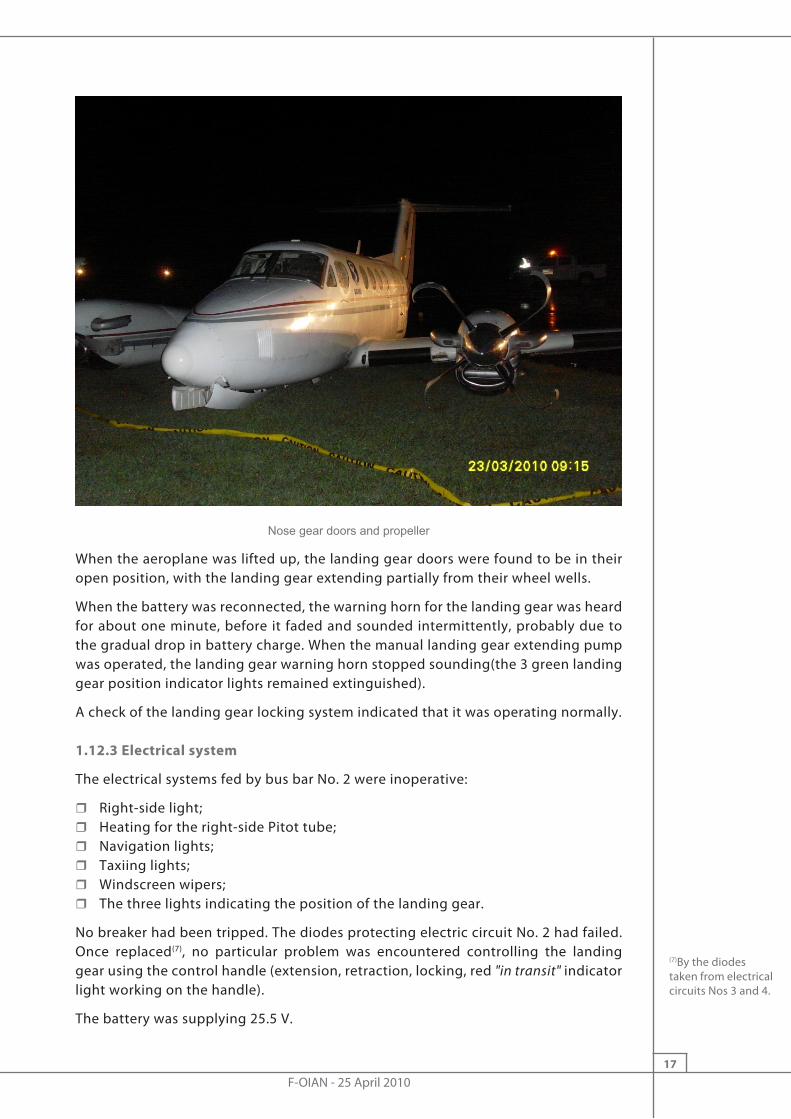
Nose gear doors and propeller
When the aeroplane was lifted up, the landing gear doors were found to be in their open position, with the landing gear extending partially from their wheel wells.
When the battery was reconnected, the warning horn for the landing gear was heard for about one minute, before it faded and sounded intermittently, probably due to the gradual drop in battery charge. When the manual landing gear extending pump was operated, the landing gear warning horn stopped sounding(the 3 green landing gear position indicator lights remained extinguished).
A check of the landing gear locking system indicated that it was operating normally.
1.12.3 Electrical system
The electrical systems fed by bus bar No. 2 were inoperative:
� Right-side light; � Heating for the right-side Pitot tube; � Navigation lights; � Taxiing lights; � Windscreen wipers; � The three lights indicating the position of the landing gear.
No breaker had been tripped. The diodes protecting electric circuit No. 2 had failed. Once replaced(7), no particular problem was encountered controlling the landing gear using the control handle (extension, retraction, locking, red "in transit" indicator light working on the handle).
The battery was supplying 25.5 V.
(7)By the diodes taken from electrical circuits Nos 3 and 4.
F-OIAN - 25 April 201018
1.13 Medical and Pathological Information
There was nothing to indicate that physiological or other factors affected the faculties of the flight crew or impaired their performance.
1.14 Fire
There was no fire.
1.15 Survival Aspects
The two members of the flight crew and the two passengers evacuated the aeroplane without encountering any particular problem.
1.16 Tests and Research
1.16.1 Investigation of the electrical failure
Ground tests were carried out on an aeroplane of the same type (supported on jacks). These tests revealed that an input on the control handle to extend the landing gear, associated with an almost simultaneous cut-off in the electrical power supply on the circuit breakers of the n° 2 electrical circuit, led to the complete opening of the landing gear doors as well as the beginning of the extension of the landing gear. The position of the doors and the landing gear was then similar to that noted when the aeroplane was lifted. The three green lights in the cockpit remained extinguished and landing gear actuation using the handle was no longer possible.
When either one of the power levers was placed in a reduced power position, the warning horn sounded to indicate that the landing gear was not locked.
1.16.2 Landing gear control handle
The landing gear control handle taken from F-OIAN(9) was fitted to another aeroplane of the same type. Its correct operation was checked.
1.16.3 Diodes fitted to electric circuit No. 2
Examination of the diodes taken from F-OIAN(10) revealed that they had failed due to a break in the internal physical link (a loose power supply pin) which created an open circuit when this pin was pulled gently.
Statistics provided by Beechcraft indicate that the failure rate for the type of diodes fitted on board F-OIAN is extremely low. This same low failure rate was confirmed for the same diodes fitted to other types of aeroplane. The documentation provided by Beechcraft does not mention the operating limit (or service life) of these diodes. They only have to be checked during the "periodic inspection of dual-bus-feeder diodes", which is performed after every 600 flying hours. The last such inspection of F-OIAN was performed in January 2009, 481 flying hours before the accident flight.
1.16.4 Hypothesis about overvoltage in the electrical system
A hypothesis relating to a lightning strike or a short circuit leading to overvoltage in the electrical system was tested to try to explain the loss of the two diodes in secondary circuit n°2, as well as the movement of the landing gear from the locked to the transit position.
(9)Reference SWITCH ASSY-LDG GR CONT 101-384137-1.
(10)Reference 70 HF 10.
F-OIAN - 25 April 201019
The electrical power supply, not only to the electric pump valve solenoid in use to retract the landing gear, but also to the electric pump power relays, depends on the position of the landing gear control handle:
� The hydraulic module valve solenoids are electrically controlled by the control handle. When the control handle is placed in the down position, the hydraulic module valve is positioned so as to direct the hydraulic fluid towards the landing gear control actuator exit chambers. The valve remains in this position as long as the landing gear control is not placed in the up position;
� The hydraulic module electric pump is powered by a different circuit that that of the control handle.
An overvoltage in the electrical system that might explain the unlocking of the three landing gear units would thus have involved the right main circuit as well as secondary circuit n° 2. In addition, between all of the aeroplane’s main and secondary circuits, only the secondary circuit n° 2 had any damage after the failure of the two protective diodes that led the circuit to be isolated and to the non-operation of the electric pump. Further, unlocking the three landing gear units implies a power supply to the hydraulic module valve solenoid and to the electric pump for sufficient time before the failure of the two diodes. Beechcraft has no feedback evidence relating to the simultaneous collapse of the three landing gear units after locking down and illumination of the three green lights in the cockpit.
The hypothesis that the unlocking of the three gear units due to an overvoltage caused by a short-circuit or lightning appears unlikely, given that it would require several specific events occurring simultaneously without causing other damage apart from that noted to the two diodes on secondary circuit n° 2.
1.17 Information on Air Alizé
Air Alizé is an operator that holds a valid air operator certificate issued by France. A Beechcraft B200 (conducting medical evacuation flights) and a Piper 31T3 (used primarily for tourist flights and corporate use) are mentioned on its air transport certificate.
Air Alizé is authorised to perform medical evacuation flights between Wallis and Nouméa aerodromes, for three month periods, with a frequency of eight flights per month.
In terms of operating the Beechcraft 200, the minimum certified flight crew consists of a single, type-rated pilot. When used as a public transport aeroplane, it is flown by two type-rated pilots.
1.18 Additional Information
1.18.1 Accounts from the flight crew
Cleared to perform an ILS approach to runway 2, the crew reduced the aeroplane’s speed to 120 kt and selected "approach" flaps before reaching the MI locator. During the descent it was raining with "light" turbulence. As he approached the ILS glide slope, the PNF moved the landing gear control handle to its "down" position and checked that the associated three green lights had lit up. He called out: "Landing gear down". The propellers were then set to high-rpm, low-pitch.

F-OIAN - 25 April 201020
At about 1,500 ft, following an electrical failure, the indicator lights on the central panel and on the lower panel, and specifically the green landing gear position indicator lights, were extinguished. The crew took out and used portable emergency lamps and noted that all the breakers were in their normal position. The meteorological conditions around the aerodrome did not encourage the crew to abandon the approach.
Due to the loss of information provided by the indicator lights, the crew decided to continue with the approach under manual control. The windscreen wipers and landing lights were inoperative.
At about 1,000 ft, when the flaps were extended to their landing position, the crew heard a discontinuous audible warning that it could not identify. This warning stopped intermittently, and the crew believed it to be caused by the electrical failure. The crew checked the position of the landing gear control handle and the flaps. The crew believed that the three greens were not lit due to the electrical failure. However, since they had seen them lit at the start of the final approach, they decided to continue with the approach and to land.
During the landing, the right-hand propeller touched the ground first. The PF attempted to control the aeroplane’s path and it came to a stop on the right-hand side of the runway. After the engines shut down, the crew and passengers left the aeroplane without sustaining any injuries. The crew then noticed that the aeroplane was resting on its fuselage.
1.18.2 Anomalies detected on the hydraulic power packs
In a letter dated 08 October 2009, the technical manager of the company responsible for maintaining F-OIAN drew the attention of the local manager of the GSAC (the local civil aviation safety organisation) to the repetitive nature of the failures affecting the hydraulic power packs, and requested an examination of the power packs received. The anomalies detected during these examinations related primarily to the very short cycle times caused by internal and/or external leaks. The intervals between cycles recorded during these examinations were 3 to 4 seconds as a minimum, and 5 to 6 minutes as a maximum, whereas in normal operation they should be approximately 15 to 30 minutes (se §1.6.7.4). These cycle interval malfunctions were observed after several hundred flights.
1.18.3 Emergency and abnormal situations
Situations created by a failure that affects the operation of the aeroplane, or which endanger aeroplane safety are known as abnormal or emergency situations respectively. The management of these situations by the crew requires aeroplane handling actions and/or actions to address the failure that in turn require aeroplane handling techniques and/or the execution of procedures. If these actions must be taken immediately then the situation is considered as an emergency, if not then it is an abnormal situation.
F-OIAN - 25 April 201021
The handling of an abnormal situation (such as the failure of an electric circuit or a landing gear locking problem) is a multi-phase process:
� Identifying and confirming the warnings (audible, visual) and the failures detected by the crew members;
� Checking the aeroplane’s flight path, depending on the circumstances;
� Performing checks, applying procedures and check-lists;
� Analysing, evaluating the possible consequences of the failure on the continuation of the flight (technical, operational, commercial, human, etc. aspects);
� Taking a decision based on the analysis conducted;
� Notifying air traffic control, cabin crew, passengers and the operator of the decision taken.
1.18.4 Similar events
1.18.4.1 The "Feedback" publication
The publication entitled "Feedback", produced by the continuing airworthiness branch of Transport Canada, provides information about problems that have been encountered and reported which have consequences on the airworthiness of aircraft. The first issue for the year 2011 specifically describes an event involving the failure of a diode fitted to an electrical dual bus for a B200:
"On approach and following the landing gear "down" selection; there was an immediate loss of all engine instruments other than the R/H engine torque gauge. In addition, the Captain’s ADI, propeller auto feather, pitot heat and intercom function were lost. The crew also noted that there was no "gear down and locked" indication. The gear doors were open however, the gear was still in the wheel wells but slightly extended. All other aeroplane indications were normal, no circuit breakers had popped and the inverters and generators appeared to be functioning normally. The crew then declared an emergency and diverted to the nearest airport with emergency facilities. On approach to the alternate airport; the crew manually extended the landing gear; however, there was still no "green" indications. Just before final landing; all of the failed aeroplane systems indications came back on line, including all three of the landing gear "green" indications. An uneventful landing was carried out."
Examination by maintenance found that a wire between a terminal block and the dual bus diode assembly was loose. Excessive heat had also damaged this diode.
Transport Canada comments:
"When inspecting or installing power diodes; it is important to ensure that the diode is firmly attached to its respective mounting, which serves as a heat sink. Diodes that carry substantial current will become overheated/damaged unless the heat is conducted away by the mounting structure. It is important to have maximum metal-to-metal contact between the base of the diode and the mounting structure. Electrical current and voltage ratings determine its physical size of a diode with the larger power diodes capable of carrying over 2,500A."
F-OIAN - 25 April 201022
1.18.4.2 Aviation Maintenance Alerts
Issue 261 dated April 2000 of the Aviation Maintenance Alerts publication (Advisory Circular No. 43-16A) issued by the FAA describes a diode failure event. During flight, the crew reported via radio that the landing gear position indicators had failed. Other cockpit indicator lights were also inoperative. By resetting the bus feed circuit breaker the crew recovered all cockpit indications. After landing, maintenance personnel discovered that one of the two diodes fitted to electric circuit No. 2 had failed. The aeroplane had flown for about 125 hours since its last maintenance inspection.
Note: The information contained in these publications is based on feedback reports on difficulties encountered in service (FAA Service Difficulty reports) that have been reviewed by Beechcraft. These reports being incomplete, Beechcraft stated that it had been unable to determine the causes of the problems identified. Consequently, Beechcraft did not publish any information for its clients.

F-OIAN - 25 April 201023
2 - ANALYSIS
2.1 Failure of Electric Circuit N° 2
In the absence of an on-board recorder, it was not possible to determine with certainty the sequence of events that began with the failure of electric circuit N° 2. However, examination of the aeroplane, accounts from the crew and the tests performed indicate that the electrical failure occurred during the approach, at some time between the crew’s actuation of landing gear extension and the full extension of the landing gear. It is likely that one of the two diodes that protect electric circuit N° 2 was already damaged before the electrical failure and that the second diode failed during actuation of the landing gear. The cause of the failure of the two diodes may have been due to the excessive number of hydraulic module cycles.
After setting the landing gear control handle to "down", the crew reported that they had seen the three green indicators lit. This would necessarily imply that the landing gear was mechanically locked in its down position. In this position, the pressure in the hydraulic circuit is released and, unless the crew physically move the landing gear control handle, the landing gear cannot retract or unlock. Moreover, the tests performed on the aeroplane after the accident revealed that inputs on the landing gear control handle actuated the landing gear correctly. Inspection of the landing gear’s locking mechanism also revealed that it was in accordance with the manufacturer’s design specifications. During the investigation, it was not possible to reproduce the sequence described by the crew, namely the illumination of the green landing gear down indicator lights followed by the unlocking of the landing gear with no action taken by the crew on the associated controls. The hypothesis of an overvoltage due to a lightning strike or to a short-circuit, leading to the unlocking of the landing gear and causing damage only to electric circuit n° 2, seems unlikely.
2.2 Management of the Electrical Failure
During the final approach, the failure of electric circuit N° 2 specifically led to the extinguishing of the cockpit panel indicator lights. The crew decided to continue with the approach under manual control with a view to landing. A few seconds later, when the crew actuated the extension of the flaps to their landing position, they did not associate the warning that they heard with the failure of the landing gear to lock in its down position, but rather with the electrical failure. Consequently, the crew did not question the strategy of continuing with their approach, and did not consider the possibility that the landing gear was not locked. The crew’s decision to continue with the final approach without performing a precise evaluation of the situation was probably reinforced by:
� The fact that the crew stated that they saw the three greens indicating that the landing gear was down after actuating the landing gear control handle;
� The failure of the circuit breakers to trip on the various cockpit panels;
� The turbulent flying conditions, at night with rain, while the windscreen wipers were no longer operating due to the electrical failure;
� The fact that he crew had certainly acquired the visual references necessary at the moment when the audible warning sounded.

F-OIAN - 25 April 201024
An assessment of the failed equipment would probably have led the crew to identify the defective electrical circuit and to observe that it also powered the landing gear position indicator lights and the actuation of the landing gear. However, consulting the diagram for the electrical system would gave implied missing the final approach, an option rejected by the crew because of the meteorological conditions, which it judged to be degraded in the vicinity of the aerodrome.
During the landing, with the landing gear in an intermediate position, wich was not possible to determine, it is likely that the wheels touched the ground first. The landing gear then moved back up into the wells leading to contact with the aeroplane’s fuselage and propellers about 1,000 metres from the threshold of runway 02.

F-OIAN - 25 April 201025
3 - CONCLUSION
3.1 Findings
� The aeroplane had a valid airworthiness certificate.
� The crew held the licences and ratings required for the flight.
� The aeroplane’s maintenance checks were up to date.
� The aeroplane was not fitted with a flight data recorder, which deprived the investigation of important information, such as indications on landing gear lockdown (or its failure).
� When it landed, the aeroplane’s landing gear doors were open.
� The landing gear control handle on the instrument panel was operational.
� The two diodes provided to protect electric circuit N° 2 were found to be inoperative.
� The warning horn that indicates that the landing gear is not down was working.
3.2 Causes of the Accident
At night in adverse meteorological conditions, the crew decided to continue with the approach and to land, while the landing gear was not locked in the down position due to the failure of the secondary electric circuit.
The origin of this failure was probably the increase in the number of operating cycles of the hydraulic power pack which delivers the hydraulic energy required to extend and retract the landing gear. This led to the failure of the diodes in the protective secondary circuit, which could not be checked in flight.
The decision to continue the approach resulted from incorrect comprehension of the electrical failure and the aural warning that sounded during the final approach. The conviction that the landing gear was locked down, associated with the meteorological conditions and the failure of the circuit-breakers to trip, did not prompt the crew to correctly assess the risk associated with the electrical failure.

F-OIAN - 25 April 201026
List of Appendices
Appendix 1
Transcript of the communications between the crew of F-OIAN and the Nadi controllers
Appendix 2
ILS runway 02 approach chart at Nadi

F-OIAN - 25 April 201027
Appendix 1
Transcript of the communications between the crew of F-OIAN and the Nadi controllers
Heure UTC Stationémettrice
Stationréceptrice Communications
13 17 09 F-OIAN APP NADI APPROACH, F-OIAN ON ONE ONE NINER DECIMAL ONE 28 APP F-OIAN F-OIAN, NADI
32 F-OIAN APP NADI, F- AN, WE ARE CRUISING FL250, WE ESTIMATE ALBAB AT 1325 AND NN VOR 1345
51 APP F-OIAN F-OIAN, CLEARED TO NOVEMBER NOVEMBER VOR VIA ALBAB. TOP OF DECSCENT, DESCEND TO FIVE THOUSAND. EXPECT THE ILS APPROACH AT NADI, SIERRA 1008.
18 16 F-OIAN APP F-AN ROGER, WE ARE PROCEEDING TO NN VOR VIA ALBAB. AT TOP OF DESCENT, WE DESCEND TO FIVE THOUSAND AND EXPECT ILS APPROACH AT NADI. QNH ONE ZERO ZERO EIGHT
31 APP F-OIAN F-AN TRACKING DIRECT TO MIKE INDIA IS AVAILABLE, ADVISE 37 F-OIAN APP F-AN, AFFIRMATIVE
42 APP F-OIAN ROGER RECLEARED TO MIKE INDIA NDB VIA ALBAB. NIL RESTRICTIONS TO PICK UP THE LOCALIZER SOUTH OF MI AND, CONFIRMING, TOP OF DESCENT, DESCEND TO FIVE THOUSAND
52 F-OIAN APP F-AN, ROGER, WE PROCEED DIRECT TO MI NDB AND WE DESCENT TO FIVE THOUSAND
19 02 APP F-OIAN F-AN, REPORT LEAVING TWO FIVE ZERO. REQUEST AN ESTIMATE MIKE INDIA AND POB
11 F-OIAN APP ROGER, WILL REPORT LEAVING TWO FIVE ZERO, POB FOUR AND CALL BACK FOR THE ESTIMATE
21 APP F-OIAN F-AN 20 08 APP F-OIAN F-AN, CHANGE QNH NADI NOW ONE ZERO ZERO SEVEN 44 APP F-OIAN F-OIAN, NADI
52 F-OIAN APP NADI, AND WE ESTIMATE MIKE INDIA NDB AT 1346 AND WE BEGINNING DESCENT NOW TO FIVE THOUSAND
21 05 APP F-OIAN F-AN AND CHANGE QNH NADI ONE ZERO ZERO SEVEN 11 F-OIAN APP QNH 1007 56 APP F-OIAN F-AN, REPORT PASSING ONE ZERO THOUSAND 22 02 F-OIAN APP F-AN, WE REPORT PASSING ONE ZERO THOUSAND 28 50 APP F-OIAN F-AN, REPORT YOUR PASSING LEVEL NOW 54 F-AN APP AH…F-AN…AH… ONE FOUR ZERO
13 28 58 APP F-OIAN F-AN, COPIED AND RECLEARED CONTINUE DESCENT TO THREE THOUSAND, ESTABLISHED ON THE LOCALISER, CLEARED ILS APPROACH RUNWAY 02
29 08 F-OIAN APP AH…CONTINUE DESCENT TO THREE THOUSAND AND CLEARED ILS APPROACH, F-AN
15 APP F-OIAN F-AN…AND DISREGARD THE ONE ZERO THOUSAND CALL…CALL AGAIN CROSSING MIKE INDIA INBOUND
24 F-OIAN APP F-AN, WILCO
31 42 F-OIAN APP F-AN, PASSING ONE ZERO THOUSAND TO THREE THOUSAND AND WE HAVE REDUCED SPEED DUE TO TURBULENCE AND WE ESTIMATE MIKE INDIA AT FOUR NINE
59 APP F-OIAN F-AN COPIED AND AH ONCE ESTABLISHED ON THE LOCALISER, YOU CLEARED FOR THE ILS APPROACH RUNWAY 02
32 08 F-OIAN APP F-AN, CLEARED ILS APPROACH 11 APP F-OIAN F-AN, CALL AGAIN CROSSING MIKE INDIA INBOUND
18 F-OIAN APP F-AN, WE CALL CROSSING MIKE INDIA NDB
41 19 F-OIAN APP AH…NADI, F-AN, THREE THOUSAND FEET, NEW ESTIMATE AT MIKE INDIA FIVE TWO
47 16 F-OIAN APP AH…NADI…F-AN 48 33 F-OIAN APP AH…NADI, F-AN AH NEW ESTIMATE AT MIKE INDIA ONE THREE FIVE TOO 55 18 F-OIAN APP AH…NADI, F-AN, CROSSING MIKE INDIA NDB
33 APP F-OIAN F-OIAN, CONFIRM CROSSING MIKE INDIA NOW? 38 F-OIAN APP F-AN, AFFIRMATIVE, WE ARE ESTABLISHED ON THE…ER..ON…ER…ILS
45 APP F-OIAN F-AN, CLEARED TO LAND RUNWAY 02, WIND IS ONE ONE ZERO AT ONE THREE KNOTS. RUNWAY SURFACE WET, RAIN OVER THE FIELD
55 F-OIAN APP AH….F-AN ROGER, CLEARED TO LAND RUNWAY 02 14 01 04 APP F-OIAN F-OIAN, TAXI TO GATE 5 VIA TAXIWAY ALFA 26 APP F-OIAN F-AN, NADI
32 F-OIAN APP EMERGENCY, EMERGENCY On évacue on s’est crashé sur le bord de la piste.
End of Transcript

F-OIAN - 25 April 201028
Appendix 2
ILS runway 02 approach chart at Nadi

Bureau d’Enquêtes et d’Analysespour la sécurité de l’aviation civile
200 rue de ParisZone Sud - Bâtiment 153
Aéroport du Bourget93352 Le Bourget Cedex - France
T : +33 1 49 92 72 00 - F : +33 1 49 92 72 03www.bea.aero