Embed Size (px)
Citation preview

REPORT NO. 370
EFFECT OF VARIATION OF CHORD AND SPAN OF AILERONS ON HINGE MOMENTS
AT SEVERAL ANGLES OF PITCH
BY B. H. MONISH
SUMMARY
Thi~ report presents the results of an investigation ofthe hinge momentsof aiferons of rarious chordsand spanson two aiq%i[s hatn”ngihe Clark Y and L?.S. A. ,97wingsectionsj supplementing the investigations described inReference~ 1 and 2, of the rolling and yawing momentsdue to similar ailerons on these two airfoil sections.
The measurements were made at mvious angles ofpitch, but at zero angle of roll and yaw, the wing chordbeing set at an angle of -!-4° to thefuselage axis. In thecase of the Clark T airfoil the measurement hare beenartendedto a pitch angle of ..@”, using ailerons of spanqua[ to 67 per cent of the wing semispan and chord equalto 20 and 30 per cent of the uing chord.
The work was done in the 10#oot tunnel of the Bureauof Standarde on models of 6(?-inch span and 10-inchchord? hating square tips, no taper in plan form orthickness, zero dihedral, and zero mceepback.
INTRODUCTION
This investigation was cmried out in cooperationwith the aeronautics branch of the Department ofCommerce and the h’ational .kdvisorv Committee
3.5 inches in chord cut from the trailing edge. Eachaileron had a companion strip or flIIerblock such thatthe two would iill the space in the wing and conformmith the wing section to within +0.02 inch. A metalend plate, cut to the section used, fastened the fll.lerblock to the wing and acted as a bearing plate for thepivot at the outer end of the aileron, while small metalstraps sunk into the upper and lower surfaces of thewing and filler block secured the ot.herend of the fillerblock. The pivot bearing at the inside end of theaileron was carried in a piece of metal sunk into thewing body in the case of ailerons of 20-inch span andinto the filler block in the case of ailerons of 10 and 15inch span. Placing alJ the ailerons on the same wingtip minimized the effect of twist in the tunnel air flowmentioned in Reference 2-I
The pi-rots were made of steel and threaded throughbrass blocks set into the ends of the aiIerons. By ti.means end play was done away with and the gapbetween the inside end of the aileron and the wing bodykept smaIL
.—..—
——
,.-
for Aeronautics, for the porpose of f~thering the /know~edge of the hinge moments of con~entionalailerons on some representative herican wing —sections. Very little work on the hinge moments ‘=7;of ailerons has been published, the most rxxtensive c=
..—.—
being that of Irtig, Owen, and Hankins. (Ref-erence 3.1
DESCRIPTION OF APPARATUS AND MODELS
A description of the tunnel and models is given inReference 1, and the profiles and” coordinates of thesections are shown ‘m Figure 1.
As it visa necess+wy to modify the hinging of theailerons from the method used when measuring rolhngand yawing moments, it was decided to construct anew set of ailerons rather than adapt the old. Figurez sho~ the scheme adopted.
All the ailerons were mounted on the right wing tip,as this had a reotwngular opening 20 inches in span by
SWoo-32210
PrmRE L—ProdIesend coordinatesof CferkY and U. 8. A. S7wbMsectfone
~ metal sting ending in a smaIIeye was placed in thetrailing edge of each aileron 10 inches from the outsideend to ftih a point of attachment for the balanceand counterweight wires.
Due to diflhdties in construction it was necessaryto Ieave a slight gap between the aiIeron leading edge —‘and the filler block. An effort was made to smooth -.-over the crack while sealing the gap, so as to dupIicate
1Afterthe completionof the work describedfn tlds ~p?r and fn References1and %onr attentfonwasdireeted ti sometheoreticalworkdesmibedfn Itefererm 4,wbkh fndkgtesthat the eombfnedresultsobteinedby summationofkta ona singfeatleronam mt exaetly the same es would be obtained by tbe use of two dlerone&ceusa ofMkenca fn the IIftWributlon.
137

138 REPORT NATIONAL ADVISORY
conditions during the rolling and yawing moment tests.Filling the cracks with a hard grease was found to beimpractical because of the added friction, A seal ofthin sheet rubber over the joint was also tried. Whenboth edges of the rubber were cemented the stretch ofthe sheet added too much restoring force and when
f
FIQUEE2.-ConstruaUon of afleronefor hinge momenti
.7EndplateJ
Wing
:>
‘Fiffer*block
Pivotblock
mewwament
Ncm..-For dlmemionedsketohof mdel see N. A. C. A. Te.chnklReDortNO.238.
only one edge was cemented the sheet fluttered exces-sively. Finally it was decided to keep the gap as smaIlas possible and ta seal it with a thin layer of petroleumjelly. This jelly added no discernible friction andmade an efleotive seal. Since previous tests haveshown that a crack introduced little or no change as
Frculls 8,-Armngement forbingemomentmeESUremO?N
long as the gap was seiled (Reference 3), this methodis believed to be satisfactory.
Figure 3 shows the method of mounting the modeland of applying the restraining forcee. The modewas placed in the tunnel so that the leading edge ofthe wing was vertical and secured in pitch, roll, andyaw. Wires from the sting led on one side over a
COMM~EE FOR AERONAUTICS
pulley to a counterweight and on the other side to abell crank, through which the forces were transmittedto a balance of the pendulum type, & motion of thobalance pan would displace the aileron from its setding,an adjusting screw and pointer were provided to bringthe aileron back to the desired position.
For all up-aileron measurements and for down-aileron measurements to an angle of pitch of 20°, thebalance and counterweight wires were kept normal tothe wind direction. For down-aileron measurements
-=s’iJ~-—-Whd whecfion - - “
. TA’
+
4
Fmum 4.-Cakokt!on of htoge moment frombalancenei T. Hfngemoment- !4%cm A’
at angles of pitch greater than 20° the balance wirewas ‘mn downstream at an angle of approximately36° to the tuhnel .asis, over a pulley, and out to thebell crank, as indicated by ,dotted lines in Figure 3,The counterweight wire was carried upstream in acorresponding manner.
METHOD OF OBSERVATION
Observationa were made at wind v~cities of 40,58.7, and 80 feet per second (respectively 27.3,40, and54.5 inibs per hour). Readings were taken at a suffi-cient number of aileron angles to determine the charac-
I
-.—-
FrauEBti.-Errer due ta tire not be!ng vertlmf. Ilinsemoment. ~msecos A#+’l%sln adn Ar
teristics of the curves desired. The ailerons were sotto the desired angle by means of the turnbuckle shownin Figure 3, and the angle was measured by nmtaltemplatw applied to the model.
I!vfotionof the balance pan which would allow theaileron to move from its setting was compensated forby an adjusting screw between the end of the bellcrank and the balance pan, a pointer and scale beingarranged for accuracy of adjustment. By this meansthe bell-crank arm was kept level, eliminating anyerror from this source.
REDUCTION OF OBSERVATIONS
The calculation of the hinge moment from. the net -reading of the balance is made with the aid of Figures —4, 5, 6, and 7. If the wires to the balance and counter-

EFFECT OF VARIATION OF CHORD AND SPAN OF AILERONS ON HINGE MOMENTS 139
weight had negligible drag, did not stretch, and re-mained normal to the wind direction, the hinge momtmtwouId equal
T h COS A’.where T= the net reading of the balance.
h= the chord of the aileron measured from thepoint of attachment of the balance wireto the pi-rot line of the aileron.
A’= the angle between the wind direction andthe pivot-to&ng line of the aileron.
Am
~GCF31!6.–Cmrection forwire&a&D. ~moment=(T— D tan A’)k cm A’
If the wire is not normal to the wind direction (fig. 5),the hinge moment is given by the expression
Thcosecos A’+-Thsincsin A’.where 90° – c= the mgle of the wire to the wind
direction.T cos ●= the cotiponent of the tension in the
bakmce wires normal to the winddirection.
h cos A’= the effective lever arm of the normalcomponent of the tension.
T sin E= the component of the tension in thebalance wire parallel to the winddirection.
h sin A’ = the effective lever arm of the paraUelcomponent of the tension.
T h sin Esin A’ and the departure of cos Efrom unitywere made negligible by making e small. Tl& was
FIG=E 7—Correctionforwirestretch
Y=T *, (nearig)
&=ong’ulardetlectloncansedunit had when aileron kml towind.
accomplished by using a long baIance wire and placingthe balance so that the deviation, ~, with full aileronmovement was distributed equally in an upstreamand downstream direction.
If the wire drag is not negligible, the true hingemoment (fig. 6) is given by the expression
(T–D tan A’) h COS A’.where D = that part of the wire drag applied to the
aiIeron.D h sin A’ = the moment on the aileron caused by the
drag of the wires. This value is ex-pressed as a correction to the measuredtension in the above fornda.
The wire drag is, of sticient magnitude to be car-ried through the computations. In computing thepart of the wire drag applied to the aileron, the drag isassumed to be uniformly distributed over that partof the wire exposed to the air stream.
The wires will change length, or stretch, with in-creasing load. The angular deflection (fig. 7) isgiven with su.fiicientaccuracy by the expression
where Y= the angular deflection due to the stretch ofthe wire.
~= the anguhr deflection due to one unit ofload when the aileron is parallel to thewind direction.
By using a steel wire of sufficient diameter thisdeflection was made negligible for the forc~ encoun-tered in this test.
For the measuraent of hinge moments on down-ailerons at pitch angles above 20° it was necessary
ofw7erw7 ofci”atkron cmqleL7--
.C%rdrias of Wkq
8 = Pifchmgle~a= 4.A = em’fcv- C7CYA-YA = 7“f= U.liA27h = Trueaiferm chard
A =A’+fl. A’=@+ fu+A+ct{h: .=9676 ‘ 20”1,3~&?:(~= 5-V”),3tv4’g=(eg7
Hi@e momen<~ =M’+MD -M. -
FIGtmsS.-Computation of h!ngemomenfi Fordown aUeronat M@ pfteh angles
to run the balance and counterweight wir~ at ana~ole of approximately 35° to the wind direction, asshown by the dotted Iines in Figure 3. The resolu-tion of the forces is shown in Figure 8. In this casethe Iift component of the force on the wir= must beconsidered.
The expression for hinge moment is given asb~~=~~’ +~f~ – 3i=
where MH = the binge moment.Ill’ = the moment due to the net tension in the
balance wire.i%= the moment due to the drag of the wire.I&= the moment due to the lift of the wire.
and M’=2’h sin A.ili~=D h Sill A’.ML=L h MS A’.
where A= the angle between the pi-rot-to4ng Lineof the aileron and the baIance wire.
A’= the angle between the pivot-to-sting lineand the wind direction.
D= that part of the wire drag apphd to thesting.
L= that part of the wire lift applied to thesting.
-.
. ..—
.—
.—. . .

140 REPORT NATIONAL ADVISORY COWKCTEE FOR AERONAUTICS
Values of the various angles for the set-ups used aregiven in Figure 8.
All results are reduced to “the usual-N.-”A. C. A.form of dimensionless coefficients as given below:
where CH= the absolute hinge moment coefficientfor one aileron.
K? = the hinge moment in pounds-feet.q = 1/2 p V*= O.001M!3 v~.c = wingchord in feet.
S’ =vring area in square feet (chord length xspan).
V =wind speed in feet per second,P = the density of air, i. e., 0.002378 slugs per
cubic foot at 15° C. and 760 mm.pressure.
A moment tending to produce clockwise rotation asviewed from the pilot’s seat is regarded as positive.All values for a single aileron~efer to an aileron on theright wing tip, and the values for the ,derons com-bined are for the right aileron up and the left ailerondown.
RESULTS
HINGE MOMENT COEFFICIENTS FOR A SINGLE AILERON
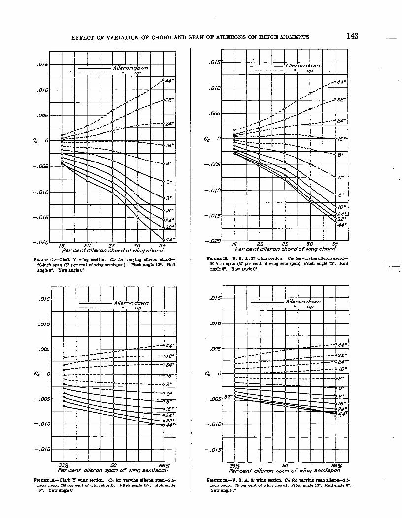
Figures 9, 11, 17, and 19 show values of hinge mo-ment coeflkients for a single aileron plotted against percent aileron chord of wing chord, and Figures 10, 12,18, and 20 the v“aluesplotted against per cent aileronspan of wing semispan. F~om the figmes it can beseen that the hinge moment varies roughly as thesquare of the chord and as the span. For ailerons ofvarying chord the rate of increase of hinge momentwith increasing chord is shgh”ilyg!reaterfor the U. S. A.27 ~ng sectionthan for the Clark Y, while for aileronsof varying span the reversw is true. In general, themoments are higher for the Clark Y section.
Zero hinge moment does.not occur at zero aileronangle, but at some upward angle whose value dependson the angle of pitch, the size of the aileron, and thewing section used. Figures 29 and 30 show this travelof angle for zero moment for two ailerons on the Clark1“ section. .,
HINGE MOMENT COEFFICIENTS FOR COMBINED AILERONS
Figures 13, 15, 21, and 23 show values of combinedhinge moment coefficients plotted against aileron anglefor ailerons of varying chord, and Figures 14, 16, 22,and 24 show values for aileronsof varying span. Fromthese it is seen that the hinge moment varies roughlyas the aileron angle. At zero degrees pitch the slopeincreases at about 20° and decreases again when theangle is greater than 30°, ._These points of increaseand decrease are not present in all of the curves for 12°pitch, most of the curves being concave downwards.
The combined hinge moments also vary nearly asthe square of the chord and as the span, with the rateof increase with increasing chord greater for the U. S. A.27 ~g section, and the rate of increase with incrOas~gspan greater for the Clark Y section.
In general, ailerona cm the Clark Y section givo agreater hinge moment coefficient than on the U, S. A.27, the difference varying with the pitch angle and thesize of aileron used.
VARIATIONOF HINGE MOMENT COEFFICIENTS WITH ANGLE OFPITCH
F~res 25, 26, 27, 28, 29, and 30 show the eflcct ofangle of pitch on hinge moments of two ailerons of20-inGh span by 2 and 3 inch chord on the ClarkY wing. Figures 25 and 26 show individual valuesand Figures 27 and 28 combined values plotted againstangle of pitch.
Figures 29 and 30 show individual values of hingemoment coefficient for one aileron at various anglesof pitch plotted against aileron angle. The cm-me arofairly smooth except at high angles of pitch, where
.-.
the curves drop suddenly in the ncighl-mrhood of 32°up-aileron. Beyond 12°, increase of pitch has lesseffect on the hinge moment.
CONCLUSION
In general, the hinge moment of an aileron variesroughly as the square of the chord and as the span.
..
The Clark Y wing sec$on gave higher bingo momentsthroughout than did the U. S. A. 27. The rato ofincrease with increasing chord was higher for theU. S. A. 27, and the rate of increase with increasingspan was higher for the Clark Y. An increase of theangle of pitch beyond 12° @d comparatively littleeffect on the hinge moment except at large upward “”displacements of the ahon, at which the hinge mo-ment dropped abruptly, changing sign in one case.
No conclusions are drawn in this report as to thomost efficient aileron~as such conclusions would ncces-sitate. a study of the rolling and yawing moments inadditiou to the hinge moments.
ACKNOWLEDGMENT.—
The author wishes to acknowledge tho assistance ofhfr. 177.C. Nlockj jr., in making the moaaurements,and of Dr. H. L. Dryden in the preparation of themanuscript.
REFERENCES
1. Heald, R. H., and strother,D. H.: Effeot of Varintion ofChord and Span of Ailerons on RolIing and YawingMomenta in LeveI Flight. 1?. A. C. A. Technical Re-port No. 298, 1928.
2. Heald,R. H., and Strother, D. H., and hfonish, B. H.: 13f-feat of Variation of Chord and Span of Ailerons on
- Rolling and Yawing Momenta at several Angles of Pilah.N. A. C. A. Technioaf Report No. 343, 1930.
3. Irving, H. B., and Ower, E., and Hankins, G. A.: An invcs-tigation of the Aerodynamic Properties of Wing Ailerons.Part I: The Effeot of Variation of l?fan Form of Wing
: -Tip, and Span of Ailerons. Aeronautical Rmmroll Com-mittee (Great Britain), R. & M. 550, 191S.
4.B3iFtahorni A. S.: Theoretical Relationship for a Wing withUnbalanced Ailerons. Aeronautical Resmrch Corn- .“.mittee (Great Britain), R. & M. 1259, 1929.
ZUREAU OF STANDARDS,
WASHINGTON, D. C.,Augud11,19S0.

EFFECT OF VARIATION OF CHOFLD AND SPAN OF AILERONS ON HINGE MOM?NTS 141 ,–
t 1 I I ‘Aileron down ! I——____ “
.oi5- w 1 ,444“-,’
.Ar .~’320/-
> .-.0!0 ,
Jf ./
/
4. Je
.Lw5
---- -- “-’- 16”–
<
–.005
-.010.
\ \’ \ ‘M’”
-.0/5 ‘24”>
~32”
-.&m
, /5 20 25 30 35Per cent aileronchord of wingcfsord
FIG~E o.~lsrk Y W@ SW410LCn for raryfng afkon rhord-mIn& span (67 ~r cent of wfng sexnkpan). Pftefr angle ~. Roll
mgte IF. Yaw angle (F
.ot5 I 1‘Aileron down
-— ____ _“UP
.0/0--~’ 44”
------
xLF#-- ---~’32”---
--- ----- --< ----- --~ 24”
.--- --- -----..--~t~~.___ --- ---
CH o ..--*8”
—. — o“
<‘8;-.005 ~ ‘[6”-
~ - 24:
-1 32--.010 \
1%! 44”
-.015
33% 50 66%Per cenf ui[eron span of wing semispon
FiocEI 1O.-C!M Y wfng asetion. C.g fm W- aDsn-2.&fnehchord (25psr rent d wing chord). PItdI arrgIeW. RoIf angIe~.YawBugleP
.0/5 ~!llb.Aife&7&wn J’44°—————— _. UP .“t
4~/
.Ofo ./ •- ,a’/- .
-“/ / / ’24°.
.m5. .“ ---
~.-. -z(#.-
------ --- --
–.005
-.OIO~ *16”
\~ ’24”
-.D15 >\
~ 44”
-.CE’O.
!5 20Per cent uikron ~rd of %g cbor%5
FIGmE IL—U.$. A. 27wfrrgaeetiou CE for mryhg aileronchord—ZHnch spe.n(67per cent of wfng semfapsn). Pitch angIeW. RoilengIeLT. Yaw angle0°
.(N5 III L ,Ailemn & wn
——————— “ UP,
.0/0
.&
<.r
-L-l - a- -’--- ‘--4 “--- ‘--
~~ -–.005
—w t44”
–.010
–.015
33fi m mgPer cenf aikmn spcm of wing semispan
FIOFSU12.-U. S. A. 27wing aeetion. C&h varying afleronSpWI–9.Mndr rhord (25 per cent of wing dsord). Pltclr angIe W. EoHanglec“. Yaw englew
—
..—

142 REPORT NATIONAL ADVLSORY COMMITTEE FOR AERONAUTICS
.0401 1’1 I 1’
k V Aikbon’d 20i~.—A AiJ&on’& 20i;.---!
.005
24°. 52- 40”Ailertm ongle, right w- tefidown
FImrEE18.-CInrk Y wfng.wetlon. CombinedCHforvergingaileronchord.Pitch engIeW. Roll angle~. Yaw engleW
.035
.030 1“V Allerori&~r:?t:i:
O ~lerdn spbn ,i5in.] chord 2.5 m
.025 +d lIeron~~a~$O;~.
.CEo/
G?
.of5 J)
//
.010 / ‘ / ‘/ { + ‘
A/ / / ‘
.0U5
o0° 8“ 16” 24° 92” 40”Aileron ongle, ri& t up - Jeff do wn
~Gurm 14.-Chrk Y wingeeatlon. CWhbfnedCEfor varying aileronepm.Pitch engleOO.Rbll engleO“. Yaw engle(P
.04a
I—~ Ailyron~:firj-A Meron an W in.—
] %-d~O 1~
.035-“ + Aileron soon ~Oin. ~ Aileron qxn 20 in.chord 2.5 u ‘~ chard 3.0 ~
O Aileron;~d2i~)
.090 - 1
/ ~
.025 - / ~/
Ca
.40 - <
.0/5 - J ●
.010 -
.005. ..
/ / ~ -
24” 32” , 40 “Aileron cwqle, right w - lef f obwn
PIGUEE16.—U.6. A.27whg section. (hmbbred C~forveryingelIeronchord.Piteb engleW. Roll engleW’. YawangleO*
Fmumr16.—U.S. A. 27 wing ration. CombLnedCR for vmybrg efkmnqmn. Plti engleW. RolIangleCF. Yew engleW
EFFECT OF VJLRIATIONOF CHORD AND SPAN OF AILERONS ON EINGE MOMENTS 143
t.0/5 IAileron gbwn. --—-——- .
P,J44”
#.010
.~. . A ~3~
/ - --.“ ~--
v.=
. .--A0 e“
H“ ~.dr &--- ---~ ~24-
–.O&
> } 0“
-.010
–.0!5
–.020 ,5
Per cen%ran %ordof b%g Chor%=
Fmcrm 17.-Clark Y wfog aectfon. CR for mrying aileron chord—ma span (67w cd of wing Semispanl. Pitch angle w. RonsngIe~. Yaw angleIY
.of5 I ,Aileron 06wn’‘
——-— —_— .r t up
.010
1
.0a5 - t I --- -+44=---
4+
I—..
& 1= -L I I I t I0“
–.005 - 8“t
16”24“
-.0/0.32”44”-
---
FrGr!ws18.—ClarkY W@ S@Ion. C.qfor varyfngafleronapan-2.E-fnchchord (25par cent of wfngchord). PItdr angle l%. Roll angIew. Yaw angfao“
.0/5 - I I ‘Aileron obwn.—--- —-- . y
**.’ ’44”.Oto e“
--”J~
-.> K7z”-,= ---
.005/ ./ v
I ..- ---
.. ---4 1- ..--~ 24”
--- --
--- --CE o <“16k-- -- ------ L--- --.
h <. --~16“
.–.005
–.010
–.015
-.020 15Zo 25 .30 35
per cent aileron cbordof wing chord
F’mwaxU.—U. 8. A. 27 wing ardfon. Cx forvaryingafleronehord-!iWfnchspan (67P& O?rltOfWhg SerttfSpa4.Pit& angleW. IiOIlangleOO. YawangfaW
.0}5 # IAileron & wn
-— -—--- -[ t up
.010
.m---.---~44”
---~*--- ---.(32=----------
● ~24”-----------
CE o-- -------~)}6”
-.(310~
-.015
33X .53 66%Per cenf aileronSpm of wing semf”span
FIQCaE2).-U. ELA. 27wiog aecrfon.C.. for wryfng m aUeron-2J-fnch ChOfi(23H cant of wfngchord). Pitch an@ Hi?.Roll a@u W.Yaw angleV
-.-—.—

144 REPORT NATIONAL ADWS-ORY
.035-’7 Aileron SPOn 20 h.-A Aileron epon 20 in.—~ chord l.5”
; A#eron~r;?O;”:J ~i,~roti~>d;:i;
I chord 3.0”0 Aileron~&d;On.
$
.030,,
.025
.lZ=’o 1-
c~ / ~ x
.015 21 ../+/
? ,/c /
.010
.005
0
Aileron ongle, righf up - Ief t down
FIGIJRE21.-Clark Y wingw&on. Combfnd CRforvaryingafkmonchord.PItohangle1%. RollangleO“. Yaw angleW
.035-
.030V Aikrontiv; :O;-:
O Aileron spon Ikin.
+ ;iferL%hd;?i; -.025chord 2.5 ~“
.020
c=
.015 4.
+/+/
-)
.010 / ~r 7
> ~
.005
00“ 8“ /6” 24” 32” 40”Aileron angle, right up- left dew%,
F1OCREZ!2.-ckk Y wing6eLWon.Cornbfnedf% for varying aileronsmn.Pftehangle17. Rollangle~. Yaw angleW
CO~E POR AERONAUTICS
-1--I
0-’I 1 I I I 1 I I 1 I
o“ 8“ 16- 24” 92” 40”Alferon ortgfe, right up - Ief t down
FrGrrrcE23.-U. S. A. 27 wing e&tlon. Cqnblned Cmfor varslng aileronchord. Pitch angIe1P. RollangIeIP. Yaw anglefP
—,
.055
.030 t
ChOrd d.t$’” AO filedn span 15in.
.025Icbord2.5 N
+ .41eron~~~Oj:–
CE
.020
.- —I,, 11111111111 I
+“+H—H-H++i-t--l
.Olb -
.0q5
—
oo“ 8“ 16- 24” 32” 40 “Ailercm ongle, right up-left down
FIafiii 24.-U. S. A, 27 wing eedion. Combined CR for vnrylng olleronepan. PItcb angleIP. Rolfangle~. Yaw angloW

EFFECT OF VARIATION OF CHORD AND SPAN OF KDJERONS ON HINGE MOMENTS 145
.015 1Ailekn cb wn “
—— ————— . UPt
.0[0
0L
(
44”( $
-.010
-.015 ~10” m“ 30” 40”
Pifch orqle
FIGLZX 2,L<W y w-@ AOZL & V- pitch ~Ie for Om
aileron. AUemnspan 20 Inches. Mleron chord 2.0 Lnc+xs. RollangIeW. Yaw engh IF
–.005
–.0/6
-.015
-.026
I 1 Aileron &wn———___ “
I UP I
<L-. .tL-. ‘R, 1-.
‘-u.”\1h‘.‘.. ‘\
‘Q t. --- ---*L ‘. \-.. . ‘\ ‘.k . -~:=’ ‘g
-u-.. . r-. >, --- ----. N -- .-
‘ rz4--
‘.-
-.? * - r16------ ---- ~~-
.- . --- 8-
< N ~. .
—, L 0“
t1 - 8“
~-
1 16”
<>1
24”32’=
1/44”
0. 10” 20” 5’0” do”,-Pifch anqle ‘-
mGUEI 23.-CLarkY wing seetkm. CE mrsus pfteh angk for oneWren. AiIeron span 20 fnehes. .Ulemn chmd 3.0 fnches. RollW@ W. YawU@ W
.03U I
.i%5
.=0
q
_015 . .(
.0[0 ~ ~44*
— 8 I\ ,
:132 “
s 7 t Q24:\ &
1(~[6”
1)
I
A<‘8”
o 0. ro- 20° 30. 40”Pifch mgle
FIGCEE27.-CIark Y wing eectlon. Cambhmd CRTarsuspitch anglafor onEaileron. AUeronspan m Inches. Ueron chord 2.0 Inches.EoIl angleO“. Yaw angleW
440
D35 -
.030
.025 \ ‘
c=
.Eo
\ ,\ t44”-
.0[5 k ~~~32“
<1.0[0 -
~ — -
~ Ii6”
.0=
o0= lo” 20° 30” 40°
Pifch w.%
FIGVRE Z&-Clark Y wing section. CombinedCm~ pitch anglefor one &OJL AIIeronePWIXI Indws. AiIeronchord 3.0 Inchee.RoJlangle0“. Yaw angle-r
----
—

146 REPORT NATIONAL ADVISORY
.0/0o
I I
x———— /g
—+----------20”-—-—.—3@A
.005 v—..—..— 40= A J
2 f
o
CH
-.005
-.0/0
-.0/5
32” /6” m 16” 32 “Aileron dew-n ‘~ileron uj-
FImJR!iZJ.-Clsrk Y wingeedion. CMTezmsdleron ongIefor verIouspitchangles. Aileronspan ZI inches. Aileronohord 2.0 Inches. Angle of rolfW. Angfeofyaw O“
COWTI’EE FOR AERONAUTICS ,
.Oio , I
—----’----2P—.——30=—..——
.00s
-d “
~.w.
-.005 /‘ ..?,/’
/ ,,~.
{/ H/ J~ —
-.oto
-.0/
32 “ 16” o“ 16” 32 “-Aileron down A!leron up
FIQUEE30.-Clark Y wfngeeetIon. C%versusallwonrmgfofor mrfous p[tchangles. Aileronspan 2QInches. Allemn chord 8.0 hrchcs. Angle of roll
W. Angleofyaw 0°

EFFECT OF VARIATION OF CHORD AND SPAN OF AILERONS ON HINGE MOMENTS 147 — —
ABLE IM.—U. S. A. 27 WING SECTION—HINGE MO-bfENT COEFFICIENT
.-TABLE I.—CLARK Y V71NG SECTION—HINGE M031ENTCOEFFICIENT
[Varyingchord of aIIerou*“; a%$$o%’%~~l$m? @at@e’ of~w,
srytng chordof afIeron. An@ ofpitch of afrplams OO;@e of attack or wfn!i+4”; anK1eof3-SW,r; englaof rod, LPI
“tm.-Ths vslnee appIy ta eI&=@hdr Ieft afkon, the slans rek to the rfght
AILERON SPAN ZI INCHES (67PEE CENT OF WING 6EM16PAN)
[NoTx.-The vshes appIy to sfther rfghghnle&alkron; the sfgnsreferh the rfghl
AILERON SPAN ‘M~CHES (67PEIt CENT OF WDJQ SE.MISPAIW
AfIemrtchrrd 2 fnchss~mj?opercentofAfkmr chordwI&n&~dj16PSTcent.of
oI
Aflaom Im A=ke
–o. mfr–. Im3
&&.mlo.mn.m~.mw.m22
:E
–’y&NJ
–.m14”–. 00UJ–.m22–. mm–. m29–. m–. 0)37-. m41–. mm–. mm
r+LCL9. a)14 $.lxal.mm “%.m ;W.0042.0H9 %.m w.ma m.Wo @.mia 4“
–k mn3–.Oms–.m+:=
.m19
.mm
. ml
.mm
.W
.m~
.(W9
–cLm16–. mm–. m24-. ORo-. mm–. w–. c4M9–. 0056-. 0m2-. m–. m–. W
+; mm.m.mm.mt’a.mm.m?4.-.ama.Oul.Olm. oIa6
–o. (m2–. m–. anlo–. mm–.CQla–.0316–.mu–.m–.m?5–.0727-.IxQa–.ml
I2*
.mll
. m17
. mm
.mm
.OmlA&
t %!’
–&mm–. am
II
–o. am–. mlz–. 0)17–. Oml-. m27–. IxUl-. m–. m4a–. m4s-. (W9–. mm–. mm
+o —
.-;: No
. m17
.Cm3
.mm
.0m4
.fnm
.m43
.0345
..—.- ---
● .J
, .=AIYeronrhord ? In@es-(20P cent of IIAfleronchord8.6fnches(36E eat of
wing chord)Wtngenorru II
18Aileron
r-rP
w –a ma4“ –. amP –. mu1Plr 4’:gIIJw24” .aw
.ma?; .Olmw .011940= .019044” .0141 rco#&e
+0&&3.0339. 012): o&ls&
.m7
:%!Jmf&
Commel
+hri&.W9.m92.0116.0144. Oln.Olm.0210.02M.0m9
Af.leronm
-o. mlo–.0235,–. m–. Dx9–. 0105–. OM–. 0134–. 0146–. Olin–.olm–. Oln–.Olm
w *. p2& ‘ –o-mm4“ –NMe -. W –. m51lr +.(#7 –.am
.m~ –.mi4% .Cmo –. mm24” -. mm
%% –.olms . mi4 –. Olulw . m- -.0125w44” :% :E
–o. m27-. m14–. ml+. mn
.m27
.m44
.mao
.0076
.mm
. Olm
.0110
.0119
-am +L251$–a mm
–. Cm2 . am 6-2. ~ .m79 Is
. ml–. mm .ca43 Z–.o112 :o~ i %“–. o125 w–. OEM .0224 w–. Ola .0244 %“–. Olm .mm *–. Olm . 02i4 44”
–a m.io–. m22–. m+. rnn.Ca27.ma.COi7.0104. 012L.0120.OMo. Olm
-0.0040 ‘ o–.oom ~+aoms
1–.0073 .0m9–. m92 .0106–. Ou .ON:&l I -m.0172
–. 0M7 .Om–. Olii Am&–. Ola!l–. olP4 .0334–. mm .mm .—
TABLE H.-CLARK Y WING SECTION—HINGE MObIENT COEFFICIENT
~emim men of dkon. AmIe of pitch of+“;-eof~aw,~ ~W~~W~O’a~kof **
TABLE IV.-U. S. A. 27 WING SECTION—HINGE*MOMENT COEFFICIENT
‘LuytugSperrofefkoa-W;~oOff~%%~e~$q? ofstw 04.hg,
[Norrr.-The values app~ to either rf@~@njti afkrow Wesflmsreferto @ @
AILERON CHORD %5INCIHES (26 PER CENT OF WING CHORD)
~ors+l?he wdues apply to fdth=ti~h;f Ie4tsdhro%the sfansrek to ths rfght
“AILERONCHORD 2.SINCHES CMPEE CENT OF ‘WINGCHORD)
4 -AIIeronapm~ fnnmp~ pet centof AileronW&~&&U per cent of
:emb:aq ,H
Afleron AI&nUP
AaeronUP
-.—
—IY
$EP16”w24”
z.%”w44”
-am -0. m-. m –. mu-.mol –.m~+:= –.mm
–.0029.mm –.0m6.mu –.IM6.0019 –.WM.0025 –.w.fml –mm.Ixa4 –.W.CcG6 –.m
I“IT+Lma 4“. m17 r.mt?a.C035 ‘ $.m45 ‘ w.Wd 24”.0m5 w. m74 W. ml 124P-~ [email protected] 44”
-1-hem. an4.fam.0029.m.m47..mm.ms9.DM6. mi2.Om
–a mu—.mo7-.Imn-1-.WU2.m.mIfl.mm.Ooa.Cw4
:%2.m?il
-a ma–. mm–.m24–.m-.m–.m42–.004s–.0oE4-.mm~.
-.mio
+4-fl&.Lm2.m44.006s.m.ml.m93. OIM. Olla. Oul
-0. OmJ–. ma–. m
$:a&.m14. mu.mm. m24.m.0231
–a m.M–. mlo–.am+:g
.mM
.0m2-Oreo.Oms.aws.mm.W6
-fL mm–.arz! + &tO&–mea–.m34 .Ln2.9–.m42 .0m2–.m .(035–.mm–.0cE4 .:%3!–.m .Olw–. m .oLm–. w . Olm–. w .0144
.—.—
.———,,
I Aileronspan Xlh&w&per cent ofwfng
—Aileronmen ZJfnches(67percent ofwfu I
aemfspin -
MeronUP =cm#l#d6Lfkronup M&n cozllb&d
v4“
S
S24”wU?Ww44”
–_:~~ ‘-.m27-. ml!–. 0242–. mm-. mm-. mm—.mi4-.omo-. Ox&–. 0m7
+ ~4
. CO(4
.Wr
.mn
.maa
.0105
. Olx
. Ol?a
. OIM
. mu
–_l..M
+: pg
. m15
. am
.mm
.0x7
.0)47
.mm
. cm?
.mi4
.-

148 REPORT NATIONAL ADVISORY COMMITTEE FOR AERONAUTICS .—
TABLE V.—CLARK Y WING SECTION—H~NGEMONIENT COEFFICIEN~”-
[Vdng chord of rdhron. Ar@ of Pitoh of ah lane, +I%; SUzleof attack o4!wfng,+16°; aogleofyaw, F, an e ofroff,0“]
[NOTE.–T’he values aPPIY to Otthorrl ht or left OkOn, the@ refexto the rfgh&ron]
rABq .VII.-U. S. A. 27 WING SECTION—HINGEBfONIENT COEFFICIENT
Var@ng chord of aflemn. Anglo of p[tchofairpfanr +1%. angleofattack ofwkrg,+16”;arrgteofyaw, ~; angle0/ roll, d“]
lJoTE.-The vahwaapply to either r~h~nfeft atfomn,tho tdgnerek to the right
JLERON SPAN, Xl INCHES (67 PER CENT OF WIN(3 SEMISPAN)AILERON SPAN 24INCHES (67 PER CENT OF WING SEMISPAN)
,, -f —Afleronchord 1,5fn$hw_(15per cant of II@ron ebord ~Inches@ p cent of AiIarOnchord 1.5fneijs (Mper csnt of
*. . wingeh@lAthon chord a frwhee
w~chord~ W at “f I
e Afleron AdfllnnUP
— — .
wing cnora) II VrlngCnom)
AfJeronUP
Ad$r# Combmed ~I
Afleron ~ A&# Cool:e4. . UPe
t i+ Of&
.W22
.mm
.fw
.0043
.0347
.aLil
.m54
.mw
.Oma
-11—1—fP : L&nf -o. m184“
-. Omo-. m4-. @mo
1% -. am2 -. fms+: ~ “-. m
% -.004324” .W14 -.0016w’ . mm -.00498P .0022 -. mmw .mm :. Co&
% :% -. m54
F -o.mm“4” –. m-m
-.0314g –. m
–. WIN10? +: g
! % .004.2; 8P .CI)17
.m
;,?$ :&?
o“4“
ISI
10”
z28’3P36”
%
-O. (EM7–. mm-. mm+: ~
.moa
:%.0m3. mlo. ma. W17
-o.om7–. Imlo–-mm-. W16-. ml!a-:0022.WJ25–. m27-mm
yg
++&.0317.mas.Oam.WB2.0m4.C#7.m42
: M!
‘F’4“
slIPw24”%“
%@44”
-a C018-. m14–. IxIll-. 0xt7–. Omz
4. mm.LHm4.Imxi
:$%.mu
–O. W18–. m-. m25–. mm-.0338-.0036-. m40–. m43–. W6-. m47-. mfs–. w
— ~.Aileron chord~c:~d30 fx?r cent of AfleronehordwMJmltio&5per cent of
\ ,...
(.:
Aflsroi chord 3 inch= 30 &r cent of\.L~, wfngchord. .
Atleronchord3.6inehm(35per cent ofwfngchord)
C.aaml:e(
-Coog-iiar
LAfleron A&unn
UP- —-_: ~; -o. mw
-.0xJ8–. #al -. WJi8–. fKm8 –. Om7+:~ –. 0025
–. 0102.Oms –. Olm.m43 –. o114.CU13S –. Oils. m71 –. o121.W31 –. Olm.Ct%9 -. OIYA
o IAfkon I ‘4””Ad:arrn Cm& ~UP
AIfeonnD e
-a mm-. m43-. m34–. Oola-. Oom+: g3#
.Q240JJo&
.0072
.m
-0. C(M.2–. 0Y6-. C(B7–. fmfl-.0109-.0118–. 01.26-.0121-. Ola?–. 0142–. 0147-. 01s1
:: p&
:%.0122.0155.0177. Olfl?
:%!.0227
-. $Eg
–. m46–. mm–, m+: $)&
.m56
.m7e
:%%. Of.w
-o.mm–. mw–. o~a–. OEM-.0137-.0146–. 0165–. 0164–.”oln–. Ofm
::3
‘o+aCKL3&
:s.0L57.Olm:%i. 02?6.0$97.om4
+l$I&l.fum.m9’J. Olla. Olm.0167.0178. Olm.0m4.oala
-0. ~b-.0055–. 0034-.0317
:. Wls.m36.mm.OJn’.0m2.Omt.0112
. .
‘AELll VIII.—U. S. A, 27 WING SEC~.ON—IHNGEMOMENT COEFFICIENT
TABLE VI.—CLARK Y WING SECTIOFJ-HING1hlOfifENT COEFFICIENT
Varyingspan ofaflerom Angle of pltoh of tiPIsne, +2”; wle of attack of TVfU+16°; angle of yaw, W; angle of roll, O’1
[Norm–The vrdneaapply tn etthar ~~nlleft aifemn,the efsm referto tie ri@
AILERON CHORD, 2.6 INCHES (35 PER CENT OF WING CHORD
TarytngSDWIofaileron. Arrgfeof tohofrdrplane,+lP; angleof attack of wing?+l@; angleo yaw, ~; angleofml~O“]
{cmE.-The v81u898PP19@ ek.horrfght or hft &ff4ZOXLtho s@9 lefOKtO therfght afleron]
AILERON CHORD 2.6 INCHES (26PER CENT OF WING CHORD),1
—n—Afferon
IA&~nn
UP
—
0 AileronUP
*nn Combtrw
+&&
.m
.om6
.m45
.0054
.0m3
. 6W2..0081
.rsRz
.0333
AfforonUP
~ %2
–. c017–. mm
;:~
. IM24
.0032
. om7. X0&4
yo~
-o.m22–.m40-.mm–.fxm-.0059–.0Qa4–.mm–.0074–.m77-.ml–. 0m3-. mm
Wdnm
i-l:::.0344.mm.0072. Ocm. W98.Olfra. Olla.0125.01=
— —-“am22 -a am–. m16 -.0020–. 0010 -.0027–. m -. m44+:=9 -. mm
-. m56. fJl16 –. mw
-. m62:%% -. om4.m -. mm.m40 ~m.m47 -. mm
~o:oJ~
–. mll–. mm–. 0m2+: ~
. mla
. mm
.0022
.m27
.0032
-a Oom–. 0024–. 0023–. oo3a–. maa–. w–. 0046-. mm–. m54-. m59:!
Ir -- glJ4“
-.om7S –. Km
i? $ @&3324”w ..m15
it :M40Q44” ,___ :%
~:g7
–.mm–.m32--mas–bmuY C041-.0044-.m467 m49–.ml–.WJ63
$.rnn:$%.0m5.W.mdl:%!.m74.(KI79. mm
+;5&4.ml,m53.0u34, m74.m23.Oom.m.0104.0107
t] .--..A.lleronspan 20tn&&i’Mr ceot ofwingAfferonspan 20ln&*p&67pezcent ofwfng
e AIfaronUI Ah&l Coml:fy
. —
Lflemn up
-a mm–. Qn7
I $:(&–.m46–. m52 .m32-. mm . am–. mm .mal
.:g~ I :=~.n I .0116
I.0124
–. mm . Olal–. m . ON-7
--- ~“ ! o+a m17
–. OoM . 0CL24–. 0062 “.fwil-. om9A 0076 :%-. Oml .Lum–. cm7 .0115;. .0129
.0142-.0101 , .Olm–.0102
I.0161
-a m28–. mlo–.mlo
w –a (x&s4“ -.00298“ -mm
Iw -.mI116° -. ml
+: M&:ix,!2W
afr :E36” .00454@ .005244” .mm
!:$t#
.mn
.mao
. f037
.m44
. m51
.mm
——

EFFECT OF VARIATION OF CHORD AND SPAN OF AILERONS ON =GE MOMENTS 149
TABLE 1X.—CLARK 1“ WING SECTION—HINGE 310- j TABLE 1X.—CLARK y IVING SECTION—HINGE IUO-lIENT COEFFICI~T I MENT COEFFICIENT—Continusd
[Voryfng chcrdofekon. Angieofpftchofeirplnne,●H@engfeofnttack ofwfng,+24°;angfeofyaw, ~; angleofro~ ~]
; [T.wyfnschordot 8flmOmAI@ Of tch Ofafr@wM,+@; W@ Oftiteck Of~P+44”;angleo yaw, O’;angfeofrow W]
[Norm–The valuesapply to either r~~~f~ ~~o% ~s~ref~totitit I Ncm.-The dm SPPIYto dthw rfE&t#J aifercmthe signsreferto the right .—
AILERON EPAN m INCHES (67 PER CEY17 OF _“Q SEM18PANl i AILER ON 6PXiV !2) INCHES (67 PER CENT OF TING SE3~SP.lNl —.,, ,:, ,.
AfIeronchti&m&e&20 PercentofI
4
‘ Affemnchord&hd&&lparcentof
a
!~.VsIues
Afferon .——
.—
8 I A.fTeaun~ =UP
I——
Aflemn 1AfleronUp I down
Afferonm
MJ3r0ron :omyui&er
-
$allo.fem.Cm22
%J.ms.0m8.m.Im93.mt
:atitib~
$:%7
: gg
.m
. OIoi
. 01Z4
.0M4
. Om
.0M9
. m77
# 8—@4“
S%w2s”62”36”40Q44”
.-,,. —..
–_a $2&
~ ~~
–. m45–. m48–.UIS2-. (W5–. mm-. mm–. w–. 0S7
-a mm–. 0m2–. ml–. mm~ :1
–. OM–.OISI–.olsi–. 0144–. Olsl–. Ofm
P’4“
1?S24”
z3$=
44” ,
]mMll ffho&’ $.Om II-
%:E%~~ ~.o14T.OLif.0182 II w.Lm3w.OmI : $.
-0.0032–. mzi–. mz–.~li–. am—. m–. faR+:s&
. m14
.mz
.0030
t 1 -a mm-. mm–. OIC-4–. OLIz–. oua–. 0s26–. 0184–. 018s–. 0146–.0L57–.0M3–. ol&i
.——
—-—.-
—.—
Ill
Narying ckrd of fdkron. An4!Jeof pitch ofairplane.+6W;angfeofattsck ofW@ ~+34”;ande ofyaw, (P;@e of@ WI I
. -.
[NoTE.-The-we 8PPIFto either rfgh;r~n{eftaflem%the 9kIISrefertothe@t i
AIL ERON SPLW 21 JXCHE5 (67 PER CENT OF I’ifXG 8EML8PAN)
Aileronchwd&hc&mm~per rent of
LAJ&ron C= 1
4:Ombin
Ve4us
1:= ,m.s& :
.awi
.0116
.0162
.OIz
.0163
. 016S
. OlmI
AUeronw
-yKei&
-.0317–. OIu–. ~i–. m+: SD&
.m
.m
:%%
Aileronm
-o. mis–. mm–. mm–. W16–. m–mm–. m16+. mnX&
–:B.%
MIelen
-0.0378–. m–mm–.oIm–.au6–.om–.0E42–.0L40—.0147–. 01.49–.016s–. Olm
-.
<~:. fmo
–. m .Om__~ .m–. m46 .am–. mm .m49–. 01s4 . 0ki7–. wi7 .0M4–. mm .=–. QM8–. m :%?–. w .fmia
—
.------- --
:.-.


LETTER OF SUBIHITTAL
NATIONAL ADVISORY COMXZIT EE FOR AERONAUTICS,
Kashin@on, D. C., tlctober 5’, 1%30.GENTLEMEN: The chairman of the ootittee on probIems of air navigation in a letter dated October 24,
1928, to the subeotittee on instruments, requested that at the outset the subcommittee prepare and submit
a report summing up the present status of air navigation instruments, and include in the report the specfic
recommendations of the subcommittee. In response to this request the subcommittee has preptired a report on
the Present Status of Airciraft Instruments, a copy of which is attached hereta.
In preparing this report it was believed inadvisable to limit the scope to a consideration of the CIESS of
instruments ordinsxily called navigation ins~ents, because the safe operation of an aircraft may depend as
Well upon the satisfactory performance of other airoraft instruments. Accordingly the scope of the report wasenlarged to include the present state of development of aircraft instruments. The customary c1aasii3cationofinstruments is folIowed in the report, which contains sections on speed, altitude, navigation, power phnt, oxygen,and fog-flying instruments. The reocmunendation.sof the subcommittee are embodied in the sections on generalproblems and summary of instrument and research problems.. The outstanding problems at the present timeare those relating to navigation in fog and to landing during fog and poor visibility. A satisfactory solution ofthose problems wiU no doubt depend largely on the use and development of radio equipment and specialinstruments. The other research problems which are outlined in this report relate mainly to the rehementof existing instruments in order to secure greater accuracy and reliability, which may greatly increase safetyduring fight.
On behalf of the subcommittee on instruments I have the honor to reoommend that the attached report bepublished as a Tech.nicaI Report of the National Advisory Committee for Aeronautics..
Respectfully,SUBCOMMITTEE ON INSTRUMENTS,
~. J. BBIGQS, ~atian.
THE EXECUTIVE COM~EE,
Nationul Adtioiy Committeefor Aeronuutim, Washington, D. C.(Through the committee on probkns of air navigation.)
ORGANIZATION
SUBCOMMITTEE ON INSTRUMENTS
Dr. L. J. Briggs, Bureau of Standards, chairman.lfr. hf. S. Boggs, Aeronautics Branch, Department of Commerce.Dr. ‘W. G. Brombacher, Bureau of Wandmds.Dr. Samuel Burka, lUat6rie1Division, Air Corps, United i%ates .tiy.
Mr. C. H. CoIv-in, Society of Automotive Engineers.Lieut. A. F. Hegenberger, Air Corps, United States Army.Dr. A. W. Hull, GeneraI Electric Co.hr. C. ‘W. Keuffel, Keu.flel & Esser Co..Mr. George W. Lewis, National Advisory Committee for Aeronautics.Lieut. T. C. Lonnquest; Burehu of Aeronautics, United States Navy.$fi. H. J. E. Reid, Kat.ional Advisory Committee for Aeronautics.
.-.—
_.-—
-—.-—.—
-
151