Embed Size (px)
Citation preview

es toepoxyf af threeedectionalarryingled that
Repair of Damaged Steel-Concrete Composite GirdersUsing Carbon Fiber-Reinforced Polymer Sheets
M. Tavakkolizadeh, A.M.ASCE,1 and H. Saadatmanesh, M.ASCE2
Abstract: The aging infrastructure of the United States requires significant attention for developing new materials and techniqueffectively and economically revive this aging system. Damaged steel-concrete composite girders can be repaired and retrofitted bybonding carbon fiber-reinforced polymer~CFRP! laminates to the critical areas of tension flanges. This paper presents the results ostudy on the behavior of damaged steel-concrete composite girders repaired with CFRP sheets under static loading. A total olarge-scale composite girders made of W355313.6 A36 steel sections and 75-mm-thick by 910-mm-wide concrete slabs were preparand tested. One, three, and five layers of CFRP sheet were used to repair the specimen with 25, 50, and 100% loss of the cross-sarea of their tension flange, respectively. The test results showed that epoxy bonded CFRP sheet could restore the ultimate load-ccapacity and stiffness of damaged steel-concrete composite girders. Comparison of the experimental and analytical results reveathe traditional methods of analysis of composite beams were conservative.
DOI: 10.1061/~ASCE!1090-0268~2003!7:4~311!
CE Database subject headings: Rehabilitation; Fiber reinforced polymers; Carbon; Girders; Concrete; Steel; Sheets.
doao
rn
omoem
dnd
oa
e
tesof
on
s-Inel
acehethee-either,m-
ird-
RPsitef-
eelofn-ofot-
n-e
iv
s
un
orbr
Introduction
Different local and federal agencies have developed programsrate bridges throughout the United States during the last fewcades. Their findings have been alerting to civil engineers natiwide. It has been found that more than one third of the highwbridges in the United States are considered substandard. Accing to the latest National Bridge Inventory~NBI! update, thenumber of substandard highway bridges in this country is mothan 167,000, more than half of which are structurally deficie~FHWA Bridge Program Group 2001!.
Steel bridges comprise more than 34% of the total numberbridges in the United States and were among the most recomended group for improvement based on the NBI report. Manythese bridges need to be repaired due to permanent damagcritically stressed locations of the tension members. These daages were caused by direct physical impact, corrosion, or growof small cracks under fatigue loading~gradual loss of the crosssection!. Considering the repair and retrofit option before deciing to replace a bridge is the rational approach. Rehabilitation arepair in most cases is far less costly than replacement. In adtion, this usually takes less time, shortening service interruptiperiods. Because there are limited resources available to mitigthe problems associated with substandard bridges, the needadopting cost-effective techniques and new materials is appar
1Assistant Professor, Dept. of Civil Engineering, Jackson State UnJackson, MS 39217.
2Professor, Dept. of Civil Engineering and Engineering MechanicThe Univ. of Arizona, Tucson, AZ 85721.
Note. Discussion open until April 1, 2004. Separate discussions mbe submitted for individual papers. To extend the closing date by omonth, a written request must be filed with the ASCE Managing EditThe manuscript for this paper was submitted for review and possipublication on April 10, 2001; approved on June 25, 2002. This papepart of theJournal of Composites for Construction, Vol. 7, No. 4, No-vember 1, 2003. ©ASCE, ISSN 1090-0268/2003/4-311–322/$18.00.
JOURNAL OF C
Downloaded 25 Oct 2009 to 194.225.128.135. Redistribution subject to
toe-n-yrd-
et
f-
fto-
th
-di-
ntefornt.
Fiber-reinforced polymers~FRPs! possess excellent mechani-cal and physical properties that make them excellent candidafor repair and retrofit of steel girder bridges. FRPs are madehigh strength filaments~tensile strength in excess of 2 GPa! suchas glass, carbon, and kevlar placed in a resin matrix. Carbfiber-reinforced polymers~CFRPs! display outstanding mechani-cal properties, with typical tensile strength and modulus of elaticity of more than 1,200 MPa and 140 GPa, respectively.addition, the CFRP laminates weigh less than one fifth of the steand are corrosion resistant.
CFRP plates or sheets can be epoxy bonded to the tension fof the damaged members to restore strength and stiffness. TCFRP sheets bridge over the damaged area and transferstresses across. The stress level in the original member will dcrease, and that will result in a longer fatigue life. There havbeen several studies on repair and retrofit of concrete girders wepoxy bonded FRP materials during the past decade; howevvery few of them have addressed the use of epoxy bonded coposite plates or sheets for strengthening and repair of steel gers.
This paper discusses the effectiveness of epoxy bonding CFsheets to the tension flange of damaged steel-concrete compogirders to restore their ultimate load-carrying capacity and stifness.
Previous Work
The most commonly used techniques for repair of damaged stbridges include strengthening of damaged members, replacingmembers, and adding of members. In general, all of these coventional techniques require heavy machinery and long periodsservice interruption, and all are costly. In most cases, they do neliminate the possibility of reoccurrence of the problem completely.
The most common attachment technique for performing coventional repair is welding. These techniques usually includ
.,
,
ste.leis
OMPOSITES FOR CONSTRUCTION © ASCE / NOVEMBER 2003 / 311
ASCE license or copyright; see http://pubs.asce.org/copyright
inteldndte
tes19ete
atetivox
ivengu
re
am
bsmasu
ththe
03heR
lonan30es
ri-ge
sh
itireesanforpigpecio
srig
d ido
he
oxtee
c-isa
ngsiteste
cleis
hnoruld
ersithe-ndk-the
mly.ne,theveerehere
ns
i-as
iseal
heo
eren
6of
welding of a cover plate to the damaged area after performgeneral clean-up and preventative measures. Unfortunawelded cover-plates pose several problems, such as the neeheavy machinery, sensitivity of the welded detail to fatigue, athe possibility of galvanic corrosion between the welded plaexisting members, and attachment materials.
The first reported application of epoxy bonding of steel plafor strengthening of concrete structures dates as far back asin Durban, South Africa, where the reinforcements in a concrbeam were accidentally left out during construction~Dussek1980!. The beam was strengthened by epoxy bonding steel plto the tension face. By 1975, in Japan, more than 200 defecelevated highway concrete slabs were strengthened with epbonded steel plates~Raithby 1980!.
In a study conducted at the University of Maryland, adhesbonding and end bolting of steel cover plates to the tension flaof steel girders provided a substantial improvement in the fatiglife of the system~Albrecht et al. 1984!. They reported an in-crease in the fatigue life of more than twenty times, as compato the welded cover plates.
In another study conducted at the University of South Floridthe possibility of using CFRP in the repair of steel-concrete coposite bridges was investigated~Sen and Liby 1994!. They testeda total of six 6.10-m-long beams made of W203310.9 steel sec-tions attached to 710-mm-wide by 115-mm-thick concrete slaThe CFRP sheets used in the study were 3.65 m long, 150wide, and had two different thicknesses of 2 and 5 mm. It wreported that CFRP laminates could considerably improve thetimate flexural capacity of composite beams.
The advantages of using advanced composite materials inrehabilitation of deteriorating bridges were investigated atUniversity of Delaware~Mertz and Gillespie 1996!. As a part oftheir small-scale tests, they retrofitted eight 1.52-m-long W234.5 steel beams using five different retrofitting schemes. Treported an average of 60% flexural capacity increase in CFretrofitted systems. They also tested and repaired two 6.4-m-corroded steel girders. The girders were typical American Stdard I shapes with depths of 610 mm and flange widths of 2mm. Their results showed an average of 25% increase in stiffnand 100% increase in the ultimate load carrying capacity.
In a study conducted by the writers at The University of Azona, the effectiveness of CFRP patches for repairing damasteel beams was investigated~Tavakkolizadeh and Saadatmane2001b!. A total of eight small-scale S12734.5 steel beams weretested. The tension flanges of six beams were cut thoroughly wtwo different depths of 3.2 and 6.4 mm, then beams were repaby CFRP patches with different lengths. A four-point bending twas performed using the displacement control loading regimeseveral unloading and reloading cycles were performed befailure of the beam. In order to avoid lateral instability, the toflanges of the beams were braced using turnbuckle and hstrength steel cables at third points and the beam was clamdown at the supports. Increases in ultimate load-carrying capaof 145% and 63% for the beams with 80% and 40% losstension flange area were reported, respectively. The stiffnesthe damaged beam after patching was recovered to 95% the onal stiffness. The different modes of failures that were observethe experiments were end peeling and delamination. They incated that the drawbacks of this technique included the lossductility and the possibility of galvanic corrosion between tCFRP plate and steel.
Very few studies have investigated the effectiveness of epbonding CFRP sheets to the tension flange of large-scale s
312 / JOURNAL OF COMPOSITES FOR CONSTRUCTION © ASCE / NOV
Downloaded 25 Oct 2009 to 194.225.128.135. Redistribution subject to
gy,for
,
64
sey
ee
d
,-
.m
l-
e
yPg-
s
d
hdtde
hd
tyfofi-
ni-f
yl-
concrete composite girders. There is only one study on the effetiveness of this technique for the repair of damaged girders. Thstudy was limited to small-scale steel girders and testing ofcouple of corroded large-scale girders.
This paper investigates the effectiveness of epoxy bondiCFRP sheets to tension flange damaged steel-concrete compogirders that lost a portion or their entire tension flange at the mocritical location. The experimental results are compared with thconventional methods of analysis. The writers in a separate artihave addressed the concern of galvanic corrosion, when CFRPused in conjunction with steel~Tavakkolizadeh and Saadatmanes2001a!. The results of this study indicated that galvanic corrosiowas not significant and that providing a thin layer of adhesivea nonmetallic composite layer between the steel and CFRP cofurther reduce it.
Experimental Study
The feasibility of epoxy bonding of CFRP sheets in restoring thultimate load-carrying capacity and stiffness of composite girdewas examined by testing three large-scale girders repaired wpultruded carbon fiber sheets. In order to observe the effectivness of this technique, three different damage levels of 25, 50, a100% loss of tension flange were considered and different thicnesses of CFRP laminates were used. The tension flanges ofgirders were cut with different total depths of 43, 86, and 171 mto simulate 25, 50, and 100% loss of tension flange, respectiveThese girders were then strengthened by epoxy bonding of othree, and five layers of CFRP sheets to the bottom surface oftension flange. Concrete slabs with two different compressistrengths were used. The overall lengths of CFRP sheets widentical and covered more than over 80% of the girder span. Tcut-off points for each layer were staggered to prevent prematufailure at termination points due to stress concentratio~Schwartz 1992!.
Materials
Tack Coat
A two-component viscous epoxy was used for bonding the lamnate to the steel flange surface. The mixing ratio of the epoxy wone part resin~bisphenal A based! to one part hardener~polyeth-ylenepolyamin! by volume. The epoxy had a pot life of 30 min atroom temperature and was fully cured after 2 days at 25°C. Thepoxy immediately reached high tack consistency and was idfor over-head applications.
Epoxy
A two-component less viscous epoxy was used for bonding tlaminates to each other. The mixing ratio of the epoxy was twparts resin~bisphenal A based! to one part hardener~polyamide!by volume. The epoxy had a pot life of 1 h at room temperatureand was fully cured after 7 days at 25°C. This epoxy had a longgel time and much lower viscosity and was used in betweCFRP sheets to insure the least entrapped voids.
CFRP
A unidirectional pultruded carbon fiber sheet with a width of 7mm and a thickness of 1.27 mm was used. After testing a total
EMBER 2003
ASCE license or copyright; see http://pubs.asce.org/copyright

s.3n
ro
t1n
l
ma
teant
n,reere-
hein
on
on.ept
w.e,
toth65,
P.35
etsnes,redce
16 straight strips~coupons! with a length of 400 mm and a widthof 25 mm, an average tensile strength of 2,137 MPa, a tenmodulus of elasticity of 144.0 GPa, and a Poisson’s ratio of 0were obtained. A typical stress-strain plot for CFRP coupotested in uniaxial tension is shown in Fig. 1~a!.
Steel
W355313.6 A36 hot rolled sections were used for the expements. A uniaxial tension test was performed on seven dog-bspecimens with a gauge length of 125 mm, a gauge width ofmm, and a thickness of 9.5 and 6.4 mm cut from flanges andweb, respectively. Average yield strengths of 354.9 and 38MPa, moduli of elasticity of 198.3 and 177.5 GPa, and Poissoratios of 0.305 and 0.299 were obtained from the specimensfrom the flange and web, respectively. A typical stress-strain pfor the flange in uniaxial tension test is shown in Fig. 1~a!. Theminimum reinforcement in concrete slabs for temperature ashrinkage was provided by using a 150315036.4 mm weldedsmooth wire mesh.
Concrete
Concrete was ordered from a ready mix plant with nominal copressive strengths of 15.5 and 27.5 MPa, slump of 100 mm,maximum aggregate size of 10 mm. Twenty 753150 mm cylin-ders were made at the time of castings and were kept withgirders during curing. They were tested under uniaxial comprsion right before the beam tests. The compressive strengthmodulus of elasticity of concrete were 16.6 and 29.1 MPa a13.8 and 19.3 GPa, respectively. Typical stress-strain plots ofconcrete with two different compressive strengths under uniaxcompression test are shown in Fig. 1~b!.
Fig. 1. Typical stress-strain behavior:~a! CFRP and steel;~b! concrete
JOURNAL OF C
Downloaded 25 Oct 2009 to 194.225.128.135. Redistribution subject
ile4s
i-ne
25he.9’s
cutot
nd
-nd
hes-ndd
heial
Specimen Preparation and Instrumentation
The steel sections were first cut into 4.9-m-long beams. Theshear studs with diameters of 13 mm and heights of 51 mm wewelded to the compression flange in two rows 125 mm on centalong the two shear spans. After constructing the forms and scuring the edges of the forms, the wire mesh was placed in tmidheight of the slab by using 38-mm-high chairs, as shownFig. 2. Two hooks made of rebar with a diameter of 12.5 mmwere welded to the top flange at quarter lengths for transportatiof the girders after casting. Slabs~753910 mm! were cast on twoseparate times and a hand-held vibrator was used for compactiSeveral 753150 mm cylinders were cast at the same time as thslabs for compression testing. The girders and cylinders were kemoist under a plastic cover for one week.
CFRP sheets were cut to the proper length with a band saFor the specimen retrofitted with one layer, a pair of 75-mm-wid3.95-m-long CFRP sheets was placed side by side and bondeda 171-mm-wide tension flange. For the specimen retrofitted withree layers, three pairs of CFRP sheets were cut to 3.95, 3.and 3.35 m long~150 mm staggers! and placed side by side on thesteel girder. For the specimen retrofitted with five layers, CFRsheets were cut to the lengths of 3.95, 3.80, 3.65, 3.50, and 3m ~75 mm staggers!. The ends of the sheets were finishedsmoothly using grid 150 sandpaper. The surfaces of the shewere sand blasted with No. 30 sand, then washed with salisolution and rinsed with fresh water. After drying of the sheetfor multiple layer systems, the surfaces of the sheets were covewith thick layers of epoxy and were squeezed together to for
Fig. 3. Endview of typical repaired girder showing binder clips andaluminum angels
Fig. 2. Formwork for concrete
OMPOSITES FOR CONSTRUCTION © ASCE / NOVEMBER 2003 / 313
to ASCE license or copyright; see http://pubs.asce.org/copyright
srio2at
rse
ew
tat
An
ceg
n
2Fut
. Inhehe
ders
e
stor0
used
the air bubbles and the excess epoxy out. Binder clips were uin close intervals for securing the edges of the sheets togethe
After the concrete slabs were completely cured, the tensflanges of the girders were cut using a Recipro Saw with a 1.mm-thick blade. The flanges of the girder with the 15.5 MPconcrete strength were cut 42.7 mm deep on both sides atmidspan~50% loss!. The tension flanges of the other two girdewith higher concrete compressive strength were cut entir~100% loss! and 21.4 mm deep on both sides at the midspan~25%loss!. Just before applying the CFRP sheets, the tension flangeach girder was sand blasted using No. 30 sand, washedsaline solution, and rinsed with fresh water.
Upon drying of the steel beam and the CFRP sheets, thecoat was mixed and applied to the tension flange surface andsheets. The cut at midspan were also filled with adhesive.pieces were covered with uniform and thin layers of tack coat awere squeezed together to force the air pockets out with exepoxy. The CFRP sheets were secured throughout their lenusing binder clips and 4034033 mm aluminum angle bars, whilethe tack coat was curing. After two hours, the extra epoxy arouthe bond area was scraped off. A typical retrofitted specimenshown in Fig. 3.
After one week, electrical strain gauges with resistance of 1Ohms were mounted on the surfaces of the steel beam, Csheets, and the concrete slab. In the midspan, the strain gawere mounted on the top and bottom of the concrete slab, the
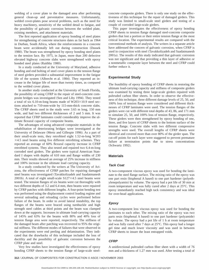
Fig. 4. Schematic of strain gauge locations at midspan
314 / JOURNAL OF COMPOSITES FOR CONSTRUCTION © ASCE / NOV
Downloaded 25 Oct 2009 to 194.225.128.135. Redistribution subject to
ed.n
7-
he
ly
ofith
ckhelldss
ths
dis
0RPgesop
flange and web of the steel beam, and on the CFRP sheetsaddition, strain gauges were mounted at the end and at tquarter-length on the CFRP sheets and the tension flange. Tlocations of the strain gauges at midspan are shown in Fig. 4.
Eight 1003100 mm wooden blocks were cut and tightly fitbetween the flanges using cider wedges at the supports and unthe loading blocks to prevent web crippling. Two loading platenon top of the slab were prepared by casting two 100340035 mmblocks using anchoring cement~Pour-Stone!. The blocks were500 mm apart and placed symmetrically on both sides of thmidspan along the center of the slab.
Experimental Setup
Four-point bending tests were performed using a 2,200 kN teframe. Loading was applied by an MTS-244.41 hydraulic actuatand an Enerpac-RRH10011 hydraulic jack with capacities of 50and 1,000 kN, respectively. The Enerpac had to be used becathe capacity of the MTS actuator was limited to 500 kN. The loa
Fig. 6. Test setup
Fig. 5. Schematic of loading setup
EMBER 2003
ASCE license or copyright; see http://pubs.asce.org/copyright

448
Table 1. Constitutive Properties of Materials
Concrete Steel CFRP
Compression I II Tension Web Flange Tension
Strength~MPa! 16.6 29.1 Yield strength~MPa! 381.9 354.9 Strength~MPa! 2,137Modulus ~GPa! 13.8 19.3 Modulus~GPa! 177.5 198.3 Modulus~GPa! 144.0Peak strain 0.00197 0.00241 Poisson’s ratio 0.299 0.305 Poisson’s ratio 0.3Failure strain 0.00399 0.00352 Strain hardening onset 0.0278 0.0263 Failure strain 0.01
A
od
t
5
a
th
u
ic
P
n,fect
hip
thee-forhe
ndndal
Thehatcu-re
reicaloree
was measured by two MTS-661.23A-02 load cells with a capacof 500 kN each and the deflection was measured by a DUNC600 series transducer with a range of675 mm. Monotonic load-ing was performed under actuator displacement control withrate of 0.025 mm/s. A total of three unloadings were carriedduring each test: before steel yielded, after steel yielded, an500 kN load level~switching from the actuator to the jack!. Theload, midspan deflection, and strains at different points werecorded with a Daytronic System 10 data acquisition system infacing with a PC through Microsoft Excel software.
The clear span was 4.78 m and the loading points were 0.apart, as shown in Fig. 5. The loading points and supports wmade using rolling blocks, and one sphere blockhead was usetransfer the load from the hydraulic jack to the spreader beThe test setup is shown in Fig. 6.
Analytical Modeling
The ultimate strength design method adopted by American Asciation of State Highway and Transportation Officials~AASHTO!was used to predict the ultimate load-carrying capacity ofdamaged and repaired girders. In addition, an incremental demation method insuring compatibility of deformations and eqlibrium of forces was used in the analysis to estimate the momecurvature behavior of the composite sections. The analytcurves were stopped when the strain in the extreme fiber inconcrete reached 0.0038.
JOURNAL OF
Downloaded 25 Oct 2009 to 194.225.128.135. Redistribution subject
ityN
autat
re-er-
mered tom.
so-
efor-i-nt-al
the
Moment-Curvature Behavior
The moment-curvature behavior of the steel-concrete-CFRgirder was predicted considering the following assumptions:
1. Linear strain variation across the depth of the cross sectio2. Perfect bond between steel, concrete, and CFRP, i.e., per
composite action and no slippage,3. Elastic-perfectly-plastic behavior for steel~«,0.025!,4. Hognestad’s parabola for concrete stress-strain relations
~Park and Paulay 1975!, and5. Linear elastic behavior for CFRP.
Uniaxial tension and compression tests were performed onmaterials in order to obtain their constitutive properties. The rsults of these tests are listed in Table 1. The stress-strain plotsthe concrete with two different compressive strengths and tcorresponding Hognestad’s parabolas are shown in Fig. 7.
In order to develop the relationship between the moment acurvature of a section, the concrete slab, top flange, web, abottom flange were discretized into ten strips each with equthickness. The CFRP sheet was considered as one layer.strain at top of the concrete slab was the primary parameter tvaried at each step and the depth of the neutral axis was callated by trial and error. A pair of values for moment and curvatuwas obtained at each point.
The ultimate compressive strength and strain for concrete weassumed to be 29.1 MPa and 0.38%, respectively. The theoretmoment-curvature plots for the damaged composite girders befretrofitting are shown in Fig. 8. It is apparent that cutting th
Fig. 7. Constitutive modeling of concrete with different strengths~I: 16.6 MPa; II: 29.1 MPa!
COMPOSITES FOR CONSTRUCTION © ASCE / NOVEMBER 2003 / 315
to ASCE license or copyright; see http://pubs.asce.org/copyright

Fig. 8. Theoretical moment-curvature plot for damaged girders
e
ioc
eio
il
i
eon
d
ssc-
3,e,e
3.eteinelu--
flange reduced the ultimate moment capacity and rigidity of thsections significantly. The ultimate moment capacity of the composite girder reduced 12, 24, and 48% while the yielding moments~moments at the onset of tension flange yielding! decreasedby 16, 33, and 67% as a result of 25, 50, and 100% loss of tensflange area, respectively. Meanwhile, the flexural rigidity of setions reduced by 14, 29, and 63% before yielding due to losses25, 50, and 100%, respectively. Three damaged sections wthen assumed to be retrofitted. CFRP provided additional tensforce to overcome the loss of steel flange. The required areacomposites was selected such that the tensile stress in the CFlayers remained between 30 and 35% of their ultimate tensstrength after the tension flange yielded. One, three, and five laers of CFRP sheet were considered for repairing the sections w25, 50, and 100% tension flange loss, respectively. The ultimamoment capacity and rigidity of the retrofitted sections increassignificantly, as shown in Fig. 9. The ultimate moment capacitythe girders with 25, 50, and 100% loss improved by 39, 107, a233%, while the yielding moment increased by 6, 25, and 85%respectively. The elastic and postelastic rigidity of the retrofitte
316 / JOURNAL OF COMPOSITES FOR CONSTRUCTION © ASCE / NOV
Downloaded 25 Oct 2009 to 194.225.128.135. Redistribution subject to
--
n-ofren
ofRPey-thtedfd,
sections increased as well. Girders with 25, 50, and 100% loshowed a 5, 21, and 75% increase in their elastic rigidity, respetively. Rigidity in the plastic region~the slope of the linear seg-ment! displayed much higher improvements and increased 6.17.3, and 29.7 times for 25, 50, and 100% loss of tension flangrespectively. A summary of the theoretical values for the ultimatcapacity and the rigidity of the sections is listed in Table 2.
Ultimate Moment Capacity (AASHTO)
AASHTO uses the Whitney’s block approximation to estimate thecompression stress in concrete at failure~AASHTO 1992!. In thisapproach, the ultimate strain in concrete is assumed to be 0.00Using this method and considering different properties for thweb and flanges, the nominal moment capacity and the ultimacurvature of the sections were obtained. The results are shownTable 3. By adding CFRP sheets to the flange of damaged stegirders, the moment capacity increased significantly and the netral axis lowered, which reduced the ultimate curvature and duc
Fig. 9. Theoretical moment-curvature plot for repaired girders
EMBER 2003
ASCE license or copyright; see http://pubs.asce.org/copyright

Table 2. Calculated Moment and Rigidity of Virgin, Damaged, and Repaired Sections (f c8529.1 MPa)
Damaged Repaired
Damagelevel
Yieldingmoment~kN.m!
Elasticrigidity
~MN.m2!
Ultimatemoment~kN.m!
Plasticrigidity
~MN.m2!Number of
CFRP layers
Yieldingmoment~kN.m!
Elasticrigidity
~MN.m2!
Ultimatemoment~kN.m!
Plasticrigidity
~MN.m2!
25% 255.7 44.57 372.1 0.630 1 272.3 46.97 516.4 3.98550% 203.9 36.78 321.2 0.581 3 254.7 44.43 665.7 10.024100% 99.8 19.32 219.0 0.519 5 185.0 33.85 729.5 15.395Virgin 305.8 51.78 422.7 0.699
tc
ein
e
h
a
2
aR
lti-hedof
theterteeirebut
etem-ion
onhape
siveto
sh-see
inor
ionheal toatinggndis,
ced.ad-theca-
tility of the section. The results of the AASHTO method wermore conservative as compared with the values obtained byiterative numerical method.
Experimental Analysis
Three composite girders were tested in the present study. All thgirders were repaired by epoxy bonding of one, three, and filayers of CFRP sheets to their tension flanges. They were sjected to monotonic loading with few unloading cycles. The loaing was applied under the displacement control regime withconstant rate of 0.025 mm/s. In the elastic region, data werelected at specified load levels, and after yielding, they were clected at specified deflection levels. The specimens were desigfor failure under concrete crushing, but other possible modesfailures that could occur were CFRP sheet rupturing, CFRP shdebonding, flange local buckling, and web crippling.
Girder with 25% Flange Damage, Repaired with OneLayer of CFRP Sheets
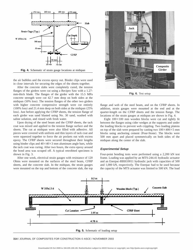
The load-deflection behavior of the repaired composite girdwith 25% loss in the flange area is shown in Fig. 10. The concrslab had an average compressive strength of 29.1 MPa. The gshowed a fairly linear response to the load from the beginniDuring the unloading cycle in the elastic region~not shown!, nosign of permanent deformation and nonlinearity was observThe elastic stiffness of the girder was 19.6 kN/mm. The bottoflange of the girder started to yield at the 166.6 kN load level. TCFRP sheet was under a tensile stress of 170.3 MPa, equal toof its ultimate strength at that point. Proceeding into the posteltic region, the girder was twice unloaded and reloaded. The elastiffnesses of the first and second reloading segments wereand 22.0 kN/mm, respectively. The girder continued to carry tload with a plastic stiffness of 6.7 kN/mm. At the 449.5 kN loalevel, the CFRP sheet started to show signs of failure~i.e., snap-ping of the edge fibers! while it was carrying 2,045 MPa, equal to96% of its tensile strength. The girder failed at 471.8 kN andultimate deflection of 49 mm. The ultimate tensile stress in CF
JOURNAL OF
Downloaded 25 Oct 2009 to 194.225.128.135. Redistribution subject
ethe
reeveub-d-heol-ol-nedof
eet
erte
rderg.
d.me8%s-
stic1.5
hed
nP
was 2,298.0 MPa, 7.5% above its average tensile strength. Umate compressive strain in the top of the concrete slab reac0.0018, which is very close to the peak strain value. The signextreme deformation at the tip of the cuts was visible andtension flange at one of the cut tips ruptured 20 mm long, affailure. A few longitudinal cracks were observed in the concreslab, but they did not have any effect on the result due to thlimited width. At the midspan, between two loading points, thweb and flanges displayed clear shear plane due to yielding,there was no buckling and crippling. In other words, the concrslab and wooden blocks stayed effective in supporting the copression flange and web up to failure. The CFRP sheet tensfailure mode was very similar to the one in the uniaxial tensitests. The sheets burst into several narrow and long needle spieces attached to the girder at their ends.
Girder with 50% Flange Damage, Repaired with ThreeLayers of CFRP Sheets
The concrete slab of the second specimen had a compresstrength of 16.6 MPa. The lower strength concrete was usedchange the mode of failure to overreinforced compression cruing of concrete. As shown in Fig. 11, the load deflection responof the composite girder was initially linear with a slight curve duto transverse cracks~shrinkage!. The stiffness of the girder in theelastic region was 20.4 kN/mm. The unloading and reloadingthe elastic region did not show any permanent deformationhysteresis. The behavior continued to be linear until the tensflange of the girder reached its yielding strain at 136.5 kN. TCFRP sheet was under a small tensile stress of 71 MPa, equ3.5% of its strength. At the load level of 245 kN, the epoxy thfilled the cut started to separate itself from the steel. Continuloading of the girder into its postelastic regime, two unloadinand reloading cycles were performed at load levels of 400 a500 kN. While both cycles showed a slight amount of hysteresthe energy dissipation in the second cycle was more pronounThe reloading stiffnesses were 20.2 and 18.3 kN/mm for reloing after reaching 400 and 500 kN, respectively. Debonding ofCFRP sheet from the steel girder in the midspan at the cut lotion ~20 mm on each side! started at the load of 480 kN. The
layers
Table 3. Calculated Ultimate Moment and Curvature of Virgin and Repaired Sections (f c8529.1 MPa)
Method Parameter Virgin 25% loss and one layer 50% loss and three layers 100% loss and five
Whitney ~AASHTO! Neutral axis~mm! 98.2 105.4 123.5 128.1Moment ~kN.m! 393.7 423.2 484.8 501.6Curvature~1/m! 0.0305 0.0285 0.0243 0.0234
Hognestad~incremental deformation! Neutral axis~mm! 74.9 82.0 98.3 108.1Moment ~kN.m! 422.7 516.4 665.7 729.5Curvature~1/m! 0.0507 0.0463 0.0387 0.0351
COMPOSITES FOR CONSTRUCTION © ASCE / NOVEMBER 2003 / 317
to ASCE license or copyright; see http://pubs.asce.org/copyright
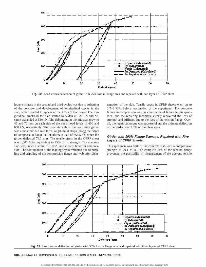
Fig. 10. Load versus deflection of girder with 25% loss in flange area and repaired with one layer of CFRP sheet
inhne
n
eeecin
toeteci-of
ver-tion
ivegesile
lower stiffness in the second and third cycles was due to softenof the concrete and development of longitudinal cracks in tslab, which started to appear at the 475 kN load level. The logitudinal cracks in the slab started to widen at 530 kN and bcame expanded at 580 kN. The debonding in the midspan grew45 and 70 mm on each side of the cut at load levels of 600 a660 kN, respectively. The concrete slab of the composite girdwas almost divided into three longitudinal strips~along the edgesof compression flange! at the ultimate load of 658.5 kN, when thegirder deflected 74.3 mm. The tensile stress in the CFRP shwas 1,606 MPa, equivalent to 75% of its strength. The concrslab was under a strain of 0.0029 and clearly failed in comprsion. The continuation of the loading was terminated due to buling and crippling of the compression flange and web after dis
318 / JOURNAL OF COMPOSITES FOR CONSTRUCTION © ASCE / NOV
Downloaded 25 Oct 2009 to 194.225.128.135. Redistribution subject to
ge--tod
er
ettes-k--
tegration of the slab. Tensile stress in CFRP sheets went up1,748 MPa before termination of the experiment. The concrfailure in compression was the clear mode of failure in this spemen, and the repairing technique clearly recovered the lossstrength and stiffness due to the loss of the tension flange. Oall, the repair technique was successful and the ultimate deflecof the girder was 1.5% of the clear span.
Girder with 100% Flange Damage, Repaired with FiveLayers of CFRP Sheets
This specimen was built of the concrete slab with a compressstrength of 29.1 MPa. The complete loss of the tension flanprevented the possibility of measurement of the average ten
Fig. 11. Load versus deflection of girder with 50% loss in flange area and repaired with three layers of CFRP sheet
EMBER 2003
ASCE license or copyright; see http://pubs.asce.org/copyright
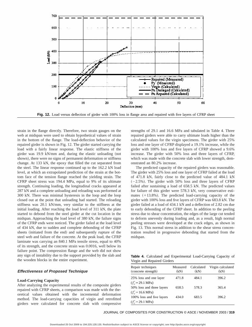
Fig. 12. Load versus deflection of girder with 100% loss in flange area and repaired with five layers of CFRP sheet
thrahthhe
somoaoha
doin
hetethnvR
R0i
on
erthonediv
eehe%the%P,-
le.d
Pesi-
ee
ngdedaln inen-he
f
strain in the flange directly. Therefore, two strain gauges onweb at midspan were used to obtain hypothetical values of stin the bottom of the flange. The load-deflection behavior of trepaired girder is shown in Fig. 12. The girder started carryingload with a fairly linear response. The elastic stiffness of tgirder was 19.9 kN/mm and, during the elastic unloading~notshown!, there were no signs of permanent deformation or stiffnechange. At 133 kN, the epoxy that filled the cut separated frthe steel. The linear response continued up to the 162.2 kN llevel, at which an extrapolated prediction of the strain at the btom face of the tension flange reached the yielding strain. TCFRP sheet stress was 194.4 MPa, equal to 9% of its ultimstrength. Continuing loading, the longitudinal cracks appeared287 kN and a complete unloading and reloading was performe300 kN. There was minimal hysteresis in the loop and the loclosed out at the point that unloading had started. The reloadstiffness was 20.1 kN/mm, very similar to the stiffness at tinitial loading. After reaching the load level of 311 kN, the plastarted to debond from the steel girder at the cut location inmidspan. Approaching the load level of 380 kN, the failure sigof the CFRP ends were noticed. The girder failed at the load leof 434 kN, due to sudden and complete debonding of the CFsheets~initiated from the end! and subsequently rupture of thesteel web and failure of the concrete. At the peak load, the CFlaminate was carrying an 840.1 MPa tensile stress, equal to 4of its strength, and the concrete strain was 0.0016, well belowfailure point. The compression flange and the web did not shany sign of instability due to the support provided by the slab athe wooden blocks in the entire experiment.
Effectiveness of Proposed Technique
Load-Carrying CapacityAfter analyzing the experimental results of the composite girdrepaired with CFRP sheets, a comparison was made with theoretical values obtained with the incremental deformatimethod. The load-carrying capacities of virgin and retrofittgirders were calculated for concrete slab with compress
JOURNAL OF C
Downloaded 25 Oct 2009 to 194.225.128.135. Redistribution subject to
einee
s
dt-eteatatpg
eselP
P%tswd
se-
e
strengths of 29.1 and 16.6 MPa and tabulated in Table 4. Thrrepaired girders were able to carry ultimate loads higher than tcalculated values for the virgin specimens. The girder with 25loss and one layer of CFRP displayed a 19.1% increase, whilegirder with 100% loss and five layers of CFRP showed a 9.6increase. The girder with 50% loss and three layers of CFRwhich was made with the concrete slab with lower strength, demonstrated an 80.2% increase.
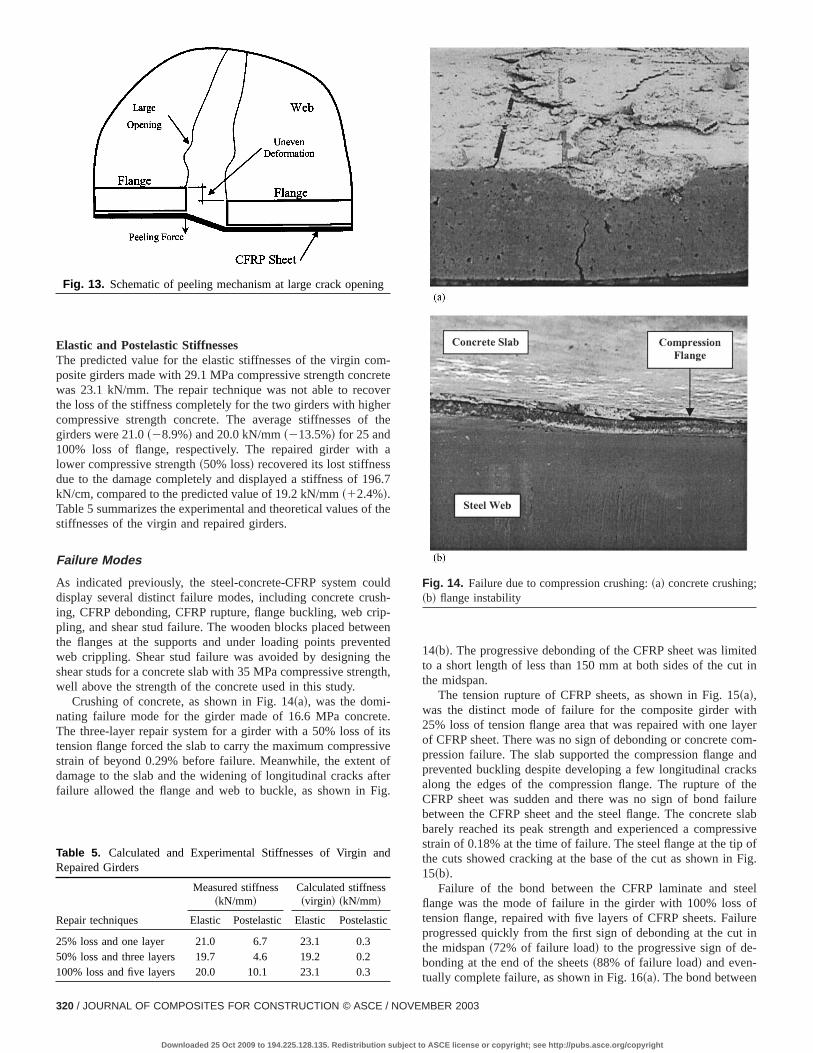
The predicted capacity of the repaired girders was reasonabThe girder with 25% loss and one layer of CFRP failed at the loaof 471.8 kN, fairly close to the predicted value of 484.1 kN~22.5%!. The girder with 50% loss and three layers of CFRfailed after sustaining a load of 658.5 kN. The predicted valufor failure of this girder were 578.3 kN, very conservative estmates ~113.8%!. The predicted load-carrying capacity of thegirder with 100% loss and five layers of CFRP was 683.8 kN. Thgirder failed at a load of 434.1 kN and a deflection of 2.82 cm duto early debonding of the CFRP sheet. In addition to the peelistress due to shear concentration, the edges of the large cut tento deform unevenly during loading and, as a result, high normpeeling stresses were developed at the crack edges, as showFig. 13. This normal stress in addition to the shear stress conctration resulted in progressive debonding that started from tmidspan.
Table 4. Calculated and Experimental Load-Carrying Capacity oVirgin and Repaired Girders
Repair techniques~concrete strength!
Measured~kN!
Calculated~kN!
Virgin calculated~kN!
25% loss and one layer( f c8529.1 MPa)
471.8 484.1 396.2
50% loss and three layers( f c8516.6 MPa)
658.5 578.3 365.4
100% loss and five layers( f c8529.1 MPa)
434.0 683.5 396.2
OMPOSITES FOR CONSTRUCTION © ASCE / NOVEMBER 2003 / 319
ASCE license or copyright; see http://pubs.asce.org/copyright
eert
a
th
lh
etee
etsv
e
edin
hyerm-
andksthelureslabsiveofig.
eelofrein
Elastic and Postelastic StiffnessesThe predicted value for the elastic stiffnesses of the virgin composite girders made with 29.1 MPa compressive strength concrwas 23.1 kN/mm. The repair technique was not able to recovthe loss of the stiffness completely for the two girders with highecompressive strength concrete. The average stiffnesses ofgirders were 21.0~28.9%! and 20.0 kN/mm~213.5%! for 25 and100% loss of flange, respectively. The repaired girder withlower compressive strength~50% loss! recovered its lost stiffnessdue to the damage completely and displayed a stiffness of 196kN/cm, compared to the predicted value of 19.2 kN/mm~12.4%!.Table 5 summarizes the experimental and theoretical values ofstiffnesses of the virgin and repaired girders.
Failure Modes
As indicated previously, the steel-concrete-CFRP system coudisplay several distinct failure modes, including concrete crusing, CFRP debonding, CFRP rupture, flange buckling, web crippling, and shear stud failure. The wooden blocks placed betwethe flanges at the supports and under loading points prevenweb crippling. Shear stud failure was avoided by designing thshear studs for a concrete slab with 35 MPa compressive strengwell above the strength of the concrete used in this study.
Crushing of concrete, as shown in Fig. 14~a!, was the domi-nating failure mode for the girder made of 16.6 MPa concretThe three-layer repair system for a girder with a 50% loss of itension flange forced the slab to carry the maximum compressistrain of beyond 0.29% before failure. Meanwhile, the extent odamage to the slab and the widening of longitudinal cracks aftfailure allowed the flange and web to buckle, as shown in Fig
Fig. 13. Schematic of peeling mechanism at large crack opening
Table 5. Calculated and Experimental Stiffnesses of Virgin andRepaired Girders
Repair techniques
Measured stiffness~kN/mm!
Calculated stiffness~virgin! ~kN/mm!
Elastic Postelastic Elastic Postelastic
25% loss and one layer 21.0 6.7 23.1 0.350% loss and three layers 19.7 4.6 19.2 0.2100% loss and five layers 20.0 10.1 23.1 0.3
320 / JOURNAL OF COMPOSITES FOR CONSTRUCTION © ASCE / NOV
Downloaded 25 Oct 2009 to 194.225.128.135. Redistribution subject to
-ter
he
.7
e
d--nd
th,
.
efr.
14~b!. The progressive debonding of the CFRP sheet was limitto a short length of less than 150 mm at both sides of the cutthe midspan.
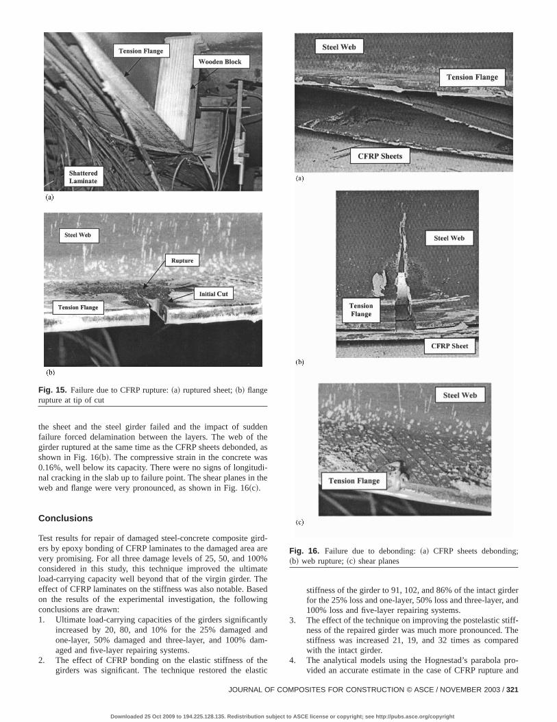
The tension rupture of CFRP sheets, as shown in Fig. 15~a!,was the distinct mode of failure for the composite girder wit25% loss of tension flange area that was repaired with one laof CFRP sheet. There was no sign of debonding or concrete copression failure. The slab supported the compression flangeprevented buckling despite developing a few longitudinal cracalong the edges of the compression flange. The rupture ofCFRP sheet was sudden and there was no sign of bond faibetween the CFRP sheet and the steel flange. The concretebarely reached its peak strength and experienced a compresstrain of 0.18% at the time of failure. The steel flange at the tipthe cuts showed cracking at the base of the cut as shown in F15~b!.
Failure of the bond between the CFRP laminate and stflange was the mode of failure in the girder with 100% losstension flange, repaired with five layers of CFRP sheets. Failuprogressed quickly from the first sign of debonding at the cutthe midspan~72% of failure load! to the progressive sign of de-bonding at the end of the sheets~88% of failure load! and even-tually complete failure, as shown in Fig. 16~a!. The bond between
Fig. 14. Failure due to compression crushing:~a! concrete crushing;~b! flange instability
EMBER 2003
ASCE license or copyright; see http://pubs.asce.org/copyright
dethed,
asdi-the
irda
0%ateese
ng
tlyanam
hesti
erand
iff-Thered
ro-and
;
the sheet and the steel girder failed and the impact of sudfailure forced delamination between the layers. The web ofgirder ruptured at the same time as the CFRP sheets debondeshown in Fig. 16~b!. The compressive strain in the concrete w0.16%, well below its capacity. There were no signs of longitunal cracking in the slab up to failure point. The shear planes inweb and flange were very pronounced, as shown in Fig. 16~c!.
Conclusions
Test results for repair of damaged steel-concrete composite gers by epoxy bonding of CFRP laminates to the damaged areavery promising. For all three damage levels of 25, 50, and 10considered in this study, this technique improved the ultimload-carrying capacity well beyond that of the virgin girder. Theffect of CFRP laminates on the stiffness was also notable. Baon the results of the experimental investigation, the followiconclusions are drawn:1. Ultimate load-carrying capacities of the girders significan
increased by 20, 80, and 10% for the 25% damagedone-layer, 50% damaged and three-layer, and 100% daged and five-layer repairing systems.
2. The effect of CFRP bonding on the elastic stiffness of tgirders was significant. The technique restored the ela
Fig. 15. Failure due to CFRP rupture:~a! ruptured sheet;~b! flangerupture at tip of cut
JOURNAL OF CO
Downloaded 25 Oct 2009 to 194.225.128.135. Redistribution subject to
n
as
-re
d
d-
c
stiffness of the girder to 91, 102, and 86% of the intact girdfor the 25% loss and one-layer, 50% loss and three-layer,100% loss and five-layer repairing systems.
3. The effect of the technique on improving the postelastic stness of the repaired girder was much more pronounced.stiffness was increased 21, 19, and 32 times as compawith the intact girder.
4. The analytical models using the Hognestad’s parabola pvided an accurate estimate in the case of CFRP rupture
Fig. 16. Failure due to debonding:~a! CFRP sheets debonding~b! web rupture;~c! shear planes
MPOSITES FOR CONSTRUCTION © ASCE / NOVEMBER 2003 / 321
ASCE license or copyright; see http://pubs.asce.org/copyright

e
relr
d
s
yr.sh
.’’
,
small loss in tension flange area. For the mode of failure duto compression crushing of concrete and moderate loss otension flange area, the theory was fairly conservative. Fosignificant loss of tension flange and in order to consider thdebonding mode of failure, the stress concentration and peeing stresses at the crack should be considered as the primacause of failure.
5. While the analytical models indicated that the ductility of theretrofitted system was less than for virgin girders, repairedgirders with small to moderate loss of their tension flangedeflected between 50 and 75 mm, which is about 1/100 an1/65 of the clear span.
6. A theoretical model for prediction of debonding of the CFRPsheets needs to be developed in order to consider the posbility of premature failure due to this phenomenon.
Acknowledgments
The writers wish to acknowledge the funding of this research bthe National Science Foundation, Grant No. CMS-9413857, DJohn B. Scalzi, Program Director. The results and conclusionpresented here are those of the writers and do not represent tviews of the National Science Foundation.
References
Albrecht, P., Sahli, A., Crute, D., Albrecht, Ph., and Evans, B.~1984!.‘‘Application of adhesive to steel bridges.’’Rep. FHWA-RD-84-037,Federal Highway Administration, Washington, D.C., 106–147.
322 / JOURNAL OF COMPOSITES FOR CONSTRUCTION © ASCE / NOVE
Downloaded 25 Oct 2009 to 194.225.128.135. Redistribution subject to A
f
-y
i-
e
American Association of State Highway and Transportation Officials~AASHTO!. ~1992!. Standard specifications for highway bridges,15th Ed., Washington, D.C.
Dussek, I.~1980!. ‘‘Strengthening of the bridge beams and similar struc-tures by means of epoxy-resin-bonded external reinforcementTransportation Research Record 785, Transportation Research Board,Washington, D.C., 21–24.
Federal Highway Administration~FHWA! Bridge Program Group.~2001!. ‘‘Count of deficient highway bridges.’’^http://www.fhwa.dot.gov/bridge&.
Mertz, D., and Gillespie, J.~1996!. ‘‘Rehabilitation of steel bridge girdersthrough the application of advanced composite material.’’NCHRPRep. 93-ID11, Transportation Research Board, Washington, D.C.1–20.
Park, P., and Paulay, T.~1975!. Reinforced concrete structures, 1st Ed.,Wiley, New York.
Raithby, K. ~1980!. ‘‘External strengthening of concrete bridges withbonded steel plates.’’Supplementary Rep. 612, Transport and RoadResearch Laboratory, Dept. of Environment, Crowthorn, U.K., 16–18.
Schwartz, M.~1992!. Composite material handbook, 2nd Ed., McGraw-Hill, New York.
Sen, R., and Liby, L.~1994!. ‘‘Repair of steel composite bridge sectionsusing carbon fiber reinforced plastic laminates.’’Rep. FDOT-510616,Florida Department of Transportation, Tallahassee, Fla.
Tavakkolizadeh, M., and Saadatmanesh, H.~2001a!. ‘‘Galvanic corrosionof carbon and steel in aggressive environments.’’J. Compos. Constr.,5~3!, 200–210.
Tavakkolizadeh, M., and Saadatmanesh, H.~2001b!. ‘‘Repair of crackedsteel girder using CFRP sheet.’’Creative systems in structural andconstruction engineering, Balkema, Rotterdam, The Netherlands,461–466.
MBER 2003
SCE license or copyright; see http://pubs.asce.org/copyright