Embed Size (px)
Citation preview

www.hydroleduc.com
REPAIR INSTRUCTIONS
FOR LEDUC TXV UP TO 120 AND DELTA PUMP SERIES

www.hydroleduc.com
REPAIR OF HYDRO LEDUC HYDRAULIC PUMP Hydraulic bent axis pump
TXV 40 to 120 series Date :
04/05/2012 Page :
Page 2 of 16 1: Exploded view / parts list:
Part number Designation Qty /
pump 3 Seal 3 5 Seal 1 8 O-ring 1 10 Needle 10 11 Washer 1 12 Spring 1 13 Anti extrusion ring 1 14 O-ring 1 16 Circlips 1 17 Circlips 1 18 Needle roller bearing 1 21 O-ring 1 22 Piston 11 26 O-ring 3 26 Return plate 1 27 Washer 1 28 Ball joint 1 29 Shaft 1 30 Roller bearing 1 33 Plastic washer 1 36 Nitrile lip seal 1 37 Seal 1 56 O-ring 1 57 O-ring 1 58 Carstick plug 1 60 Cylinder barrel 1 65 Internal ring 1 67 Washer 1 68 O-ring 1 70 Circlips 1 73 Screw 2 77 Bearing shell 2 88 Plastic tube 1 96 O-ring 1 98 Shim 1 99 Internal ring 1
110 O-ring 1

www.hydroleduc.com
REPAIR OF HYDRO LEDUC HYDRAULIC PUMP Hydraulic bent axis pump
TXV 40 to 120 series Date :
04/05/2012 Page :
Page 3 of 16
TXV 40 TO 92

www.hydroleduc.com
REPAIR OF HYDRO LEDUC HYDRAULIC PUMP Hydraulic bent axis pump
TXV 40 to 120 series Date :
04/05/2012 Page :
Page 4 of 16
TXV 120

www.hydroleduc.com
REPAIR OF HYDRO LEDUC HYDRAULIC PUMP Hydraulic bent axis pump
TXV 40 to 120 series Date :
04/05/2012 Page :
Page 5 of 16
Fig.1 Fig.2. Fig.3 Fig.4
2: Disassembly / Assembly: Disassembly process: 1 - Clean the pump and Mark the rear cover 4 and the
housing (Pay attention: the cover has to be reassembled in the same position).
2 - Put the pump in a bench clamp and then loosen the
four screws holding the LS control (Allen key 4). Look at Fig.1.
3 - Remove the vent tube and the lead inside a screw head
located on the front cover. Fig.2. 4 - Loosen the four screws (Allen key 12). Look at Fig.3. 5 - Remove slowly the front cover. Look at Fig.4.
Pay attention: when you pull out the front housing to hold in the same the cylinder barrel.
www.hydroleduc.com
REPAIR OF HYDRO LEDUC HYDRAULIC PUMP Hydraulic bent axis pump
TXV 40 to 120 series Date :
04/05/2012 Page :
Page 6 of 16 Fig.5. Fig.6. Fig.7. Fig.8.
6 - Put the pump on a multipurpose workbench with a hole
to pass through the drive shaft end. Fig.5. 7 - Remove the plate and check it to ensure no mark of
cavitation or scratches. Fig.6. 8 - Remove the retainer ring from the drive shaft and then
the bearing inner ring. If the bearing inner ring cannot be removed, warm it and push out in the same time with a screwdriver. Fig.7.
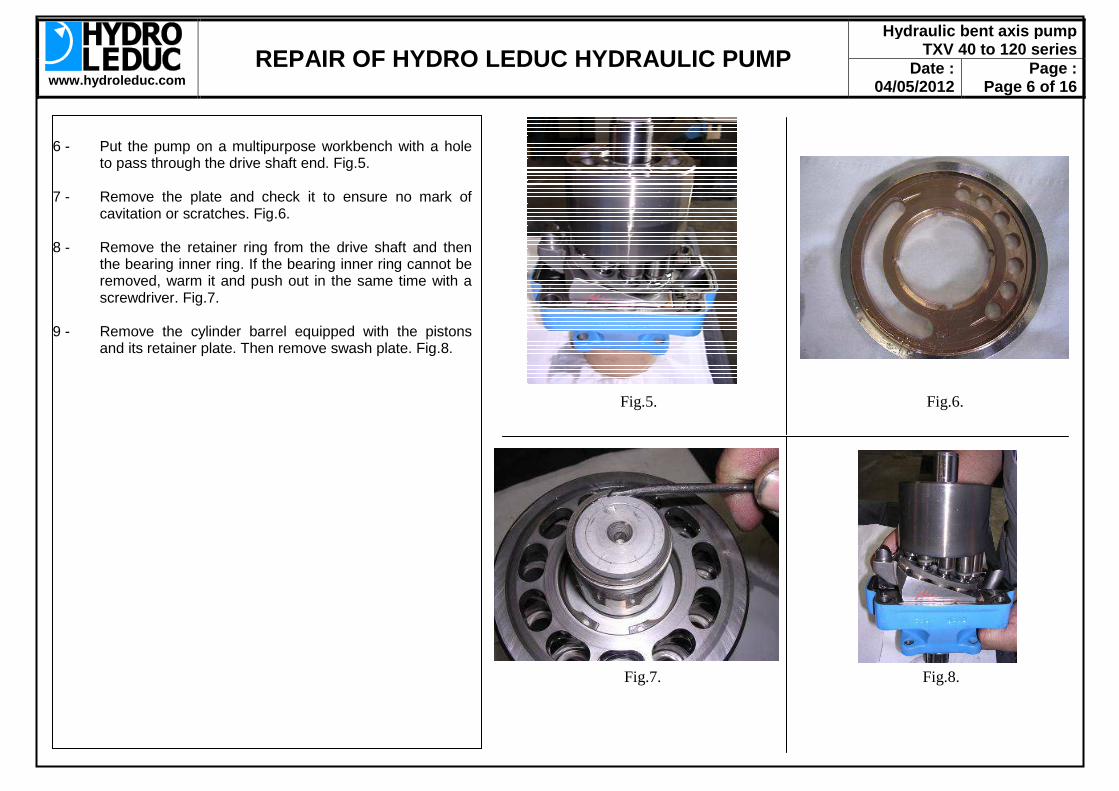
9 - Remove the cylinder barrel equipped with the pistons
and its retainer plate. Then remove swash plate. Fig.8.

www.hydroleduc.com
REPAIR OF HYDRO LEDUC HYDRAULIC PUMP Hydraulic bent axis pump
TXV 40 to 120 series Date :
04/05/2012 Page :
Page 7 of 16 Fig.9. Fig.10. Fig.11. Fig.12.
10 - Pull out the Viton lip seal with a screwdriver. Fig.9.
(after disassembling this seal cannot be reused). 11 - Remove the plastic shim between the two lip seals.
Fig.10. 12 - Pull out the Nitrile lip seal by perforating it with a
screwdriver and making lever. Fig.11. (after disassembling this seal cannot be reused).
13 - Pull out the circlips which holding the drive shaft.
Fig.12. Then remove the shaft from the front housing.

www.hydroleduc.com
REPAIR OF HYDRO LEDUC HYDRAULIC PUMP Hydraulic bent axis pump
TXV 40 to 120 series Date :
04/05/2012 Page :
Page 8 of 16 Fig.13. Fig.14.
14 - Pull out the roller bearing and the lip seal bracket from
the front housing, by slightly heating the lip seal bracket and pushing them with a hydraulic press. Fig.13.
If you have to replace drive shaft, bushing or the roller bearing, follow the disassembling procedure below: 15 - Pull out the bushing for the lip seals from the drive
shaft. Apply a hammer blow on the bushing to break it and pull it out easily. Fig.14.
16 - Pull out the internal ring of the roller bearing from the
drive shaft. Use a hydraulic press to push it. Fig.15.
Fig.15.

www.hydroleduc.com
REPAIR OF HYDRO LEDUC HYDRAULIC PUMP Hydraulic bent axis pump
TXV 40 to 120 series Date :
04/05/2012 Page :
Page 9 of 16 Fig.1. Fig.2. Fig.3.
Reassembly process: 1 - Clean carefully all the spare parts, excluding the seals
(with cleaner HAKUPUR 1025 for example). Then check carefully every spare parts.
If you need to replace the drive shaft, roller bearing or bushing look at the page N°10.
2 - Install the O-ring 56 on the lip seal bracket and apply
some grease on it. See Fig.1. 3 - Heat the front housing at 80-90°C Fig.2. and as semble
first the roller bearing 30 with glue LOCTITE 630 or equivalent, then the lip seal bracket into the front housing with LOCTITE® 641 (Pay attention of the O-ring during assembling). See Fig.3.
Grease

www.hydroleduc.com
REPAIR OF HYDRO LEDUC HYDRAULIC PUMP Hydraulic bent axis pump
TXV 40 to 120 series Date :
04/05/2012 Page :
Page 10 of 16
Fig.4. Fig.5.
4 - Apply LOCTITE 641® on the drive shaft (red surface on
Fig.4.). Heat the bushing 65 at 110°C and assemble it without shock.
5 - Put the drive shaft (splines to the top) and install the
internal ring of the roller bearing 30 as Fig.5. 6 - Install the front cover onto the drive shaft and then
mount the bearing inner ring and the bushing, as Fig.6. 7 - Assemble the circlips into its groove. Fig.7. Pay attention: do not scratch the bushing during
assembly.
Fig.6. Fig.7.

www.hydroleduc.com
REPAIR OF HYDRO LEDUC HYDRAULIC PUMP Hydraulic bent axis pump
TXV 40 to 120 series Date :
04/05/2012 Page :
Page 11 of 16
Fig.8. Fig.9.
8 - Apply grease on the lip and assemble the Nitrile lip seal
32 (spring toward inside). Fig.8. 9 - Assemble the plastic washer into its groove. Pay
attention the open of the washer is in front of the vent hole and apply white grease on it. Fig.9.
10 - Apply grease on the lip and assemble the Viton lip seal
68 (spring toward outside). Fig.10. 11 - Assemble the bearing shells 77 onto the front housing,
apply glue on the screws (LOCTITE® 270 or equivalent) and tighten at 3 Nm. Fig.11.
Pay attention: the extremity of the bearing shells have to be in contact.
Fig.10. Fig.11.

www.hydroleduc.com
REPAIR OF HYDRO LEDUC HYDRAULIC PUMP Hydraulic bent axis pump
TXV 40 to 120 series Date :
04/05/2012 Page :
Page 12 of 16
Fig.12. Fig.13.
12 - Assemble the O-ring 96 with grease. Fig.12. Pay attention: the O-ring is mounted properly inside
its groove. 13 - Apply grease or oil on the bearing shells and then install
the swash plate onto the front housing with the small driver on the stop side. Fig.13.
14 - The cylinder barrel is equipped with the spring. Apply
grease to the internal splines and then install the six pins 10 and the ball bearing. Fig.14.
15 - Apply oil inside the cylinder barrel bores and then
assemble the pistons with the retainer plate onto the cylinder barrel, as Fig.15.
Fig.14. Fig.15.
Small driver Stop side
www.hydroleduc.com
REPAIR OF HYDRO LEDUC HYDRAULIC PUMP Hydraulic bent axis pump
TXV 40 to 120 series Date :
04/05/2012 Page :
Page 13 of 16
Fig.16. Fig.17.
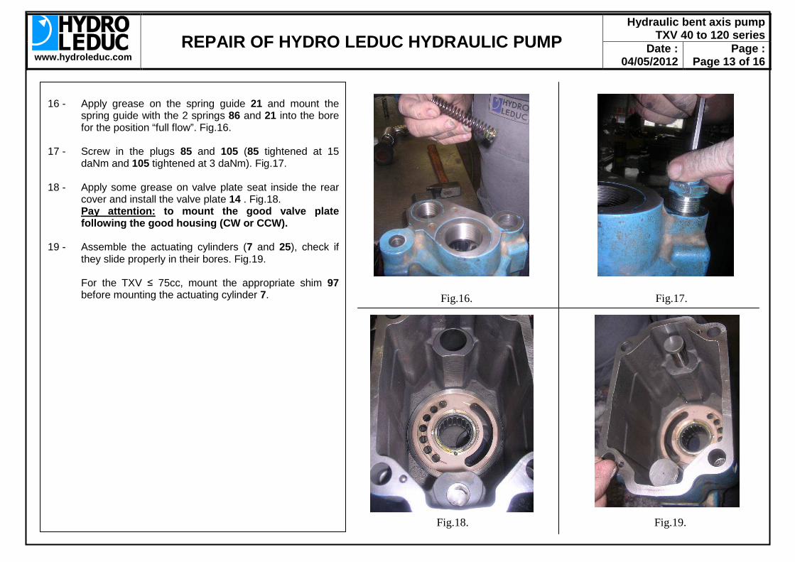
16 - Apply grease on the spring guide 21 and mount the
spring guide with the 2 springs 86 and 21 into the bore for the position “full flow”. Fig.16.
17 - Screw in the plugs 85 and 105 (85 tightened at 15
daNm and 105 tightened at 3 daNm). Fig.17. 18 - Apply some grease on valve plate seat inside the rear
cover and install the valve plate 14 . Fig.18. Pay attention: to mount the good valve plate
following the good housing (CW or CCW). 19 - Assemble the actuating cylinders (7 and 25), check if
they slide properly in their bores. Fig.19. For the TXV ≤ 75cc, mount the appropriate shim 97
before mounting the actuating cylinder 7. Fig.18. Fig.19.

www.hydroleduc.com
REPAIR OF HYDRO LEDUC HYDRAULIC PUMP Hydraulic bent axis pump
TXV 40 to 120 series Date :
04/05/2012 Page :
Page 14 of 16
Fig.20. Fig.21.
20 - Install the cylinder barrel equipped onto the front cover.
Fig.20. 21 - Install the needle bearing inner ring and the retainer
spring. Fig.21. Pay attention: the retainer spring is mounted properly into its groove.
22 - Move into position the housing on the front cover with the small actuating cylinder on the big driver. Fig.22. Pay attention: Hold the 2 actuating cylinders until they come in contact with the swash plate.
23 - Apply some glue (LOCTITE® 2701 or equivalent) on the four screws 34. Tighten the screws in cross with pre-torque at 6 daNm and final tightening torque at 23 daNm. Fig.23.
Between the pre-torque and the final tightening torque, we advise to turn the drive shaft on few turns with the appropriate rotation direction (CW or CCW according to the pump).
Fig.22. Fig.23.
Big driver
Small cylinder

www.hydroleduc.com
REPAIR OF HYDRO LEDUC HYDRAULIC PUMP Hydraulic bent axis pump
TXV 40 to 120 series Date :
04/05/2012 Page :
Page 15 of 16
Fig.24. Fig.25.
24 - Replace the 3 O-rings 26 on the LS control and apply
some grease on them. Fig.24. 25 - Assemble the LS control onto the pump and tighten the
four screws at 0,85 daNm. Fig.25. 26 - Install a new vent tube. Fig.26. 27 - Install a lead inside 1 screw head. Fig.26.

www.hydroleduc.com
REPAIR OF HYDRO LEDUC HYDRAULIC PUMP Hydraulic bent axis pump
TXV 40 to 120 series Date :
04/05/2012 Page :
Page 16 of 16 An example of a test stand schematic to check the pump:
5: Checking procedure for test stand: 1 - Connect the inlet and outlet line to the pump. 2 - Fill it the pump with hydraulic oil. 3 - Ensure the pump is setting for the right direction of
rotation (CW or CCW). 4 - Run the pump at N=1500rpm, this is the speed at which
we take all measurements. 5 - Check the stand-by pressure and set it if necessary (the
stand-by pressure setting has to be between 25 and 40 bar for satisfactory operation).
6 - Check the cancellation pressure and set it if necessary,
maximum setting pressure is: • 400 bar for TXV40/60/75 • 380 bar for TXV92 • 360 bar for TXV120
7 - Check the volumetric efficiency at 250 bar. It has to be
superior at 95 percents. (Q at 250 bar) / (Q at 0 bar) ≥ 95%
Setting pressure ≤ 400 bar Only for safety reason.
LS
Valve closed: Check the stand-by pressure
Valve closed:
Check the cancelling pressure
LS line
T
M