Embed Size (px)
Citation preview
Description: Thermocouple V1 Part number: 623020 Look for Service Centres, Point of Sale addresses and other information on: www.thetford.eu
Version: V1
Date: 04-03-2010
Tools required: Spanner 7mm
Repair instruction
A B
05/09

Repair instruction
A
B
C
Description: Fin clip Part Number: 623023 Look for Service Centres, Point of Sale addresses and other information on: www.thetford.eu
Version: V1
Date: November 2010
Tools required:
Note: be aware on which fin the original fin clip is positioned.
D
1/1 11/10 634517
Place capilary tube back into new fin clip and push it back onto the fin.
Remove capilary tube from fin clip. Note: be carefull with bending the capilary tube. In case it cracks, thermostat needs to be replaced.
Pull fin clip off the fin.
Repair instruction
A
B
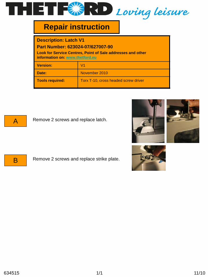
Description: Latch V1 Part Number: 623024-07/627007-90 Look for Service Centres, Point of Sale addresses and other information on: www.thetford.eu
Version: V1
Date: November 2010
Tools required: Torx T-10, cross headed screw driver
Remove 2 screws and replace latch.
1/1 11/10 634515
Remove 2 screws and replace strike plate.

Repair instruction
A
B
C
Description: Control knob Part Number: 62302507/62302607-30/62568207-30 Look for Service Centres, Point of Sale addresses and other information on: www.thetford.eu
Version: V1
Date: November 2010
Tools required:
Pull knob from axle.
1/1 11/10 634504
Make sure the new knob has the same geometry as the knob you removed. Note: if this is incorrect the indicator of the knob will not match with the icons on the refrigerator.
Push new knob on axle.
Repair instruction
A
B
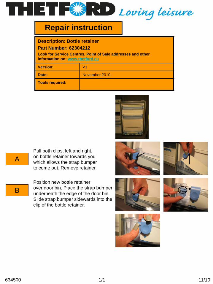
Description: Bottle retainer Part Number: 62304212 Look for Service Centres, Point of Sale addresses and other information on: www.thetford.eu
Version: V1
Date: November 2010
Tools required:
Pull both clips, left and right, on bottle retainer towards you which allows the strap bumper to come out. Remove retainer.
1/1
Position new bottle retainer over door bin. Place the strap bumper underneath the edge of the door bin. Slide strap bumper sidewards into the clip of the bottle retainer.
11/10 634500

Repair instruction
A
Description: Freezer door Part Number: 623043-08 Look for Service Centres, Point of Sale addresses and other information on: www.thetford.eu
Version: V1
Date: November 2010
Tools required: Philips screwdriver
B
1/1 12/10 634537
Place freezer door in front of freezer cabinet, pushing it up and inwards, (against the tension of the springs in the hinges), place screws back.
Remove 2 screws attaching the freezer door hinges to the bottom of the freezer cabinet. Remove freezer door.

Repair instruction
A
B
Description: Thermistor Part Number: 623077 Look for Service Centres, Point of Sale addresses and other information on: www.thetford.eu
Version: V1
Date: November 2010
Tools required:
C
1/1 11/10 634523
Remove thermistor from fin clip.
Pull fin clip off the fin
Note: be aware on which fin the original fin clip is positioned.
D
Disconnect the connector by pushing in clip on the side.
Push new thermistor in and place fin clip back onto the fin.
Repair instruction
A
B
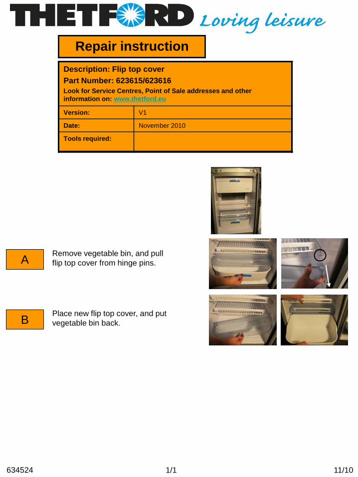
Description: Flip top cover Part Number: 623615/623616 Look for Service Centres, Point of Sale addresses and other information on: www.thetford.eu
Version: V1
Date: November 2010
Tools required:
1/1 11/10 634524
Place new flip top cover, and put vegetable bin back.
Remove vegetable bin, and pull flip top cover from hinge pins.
Repair instruction
A
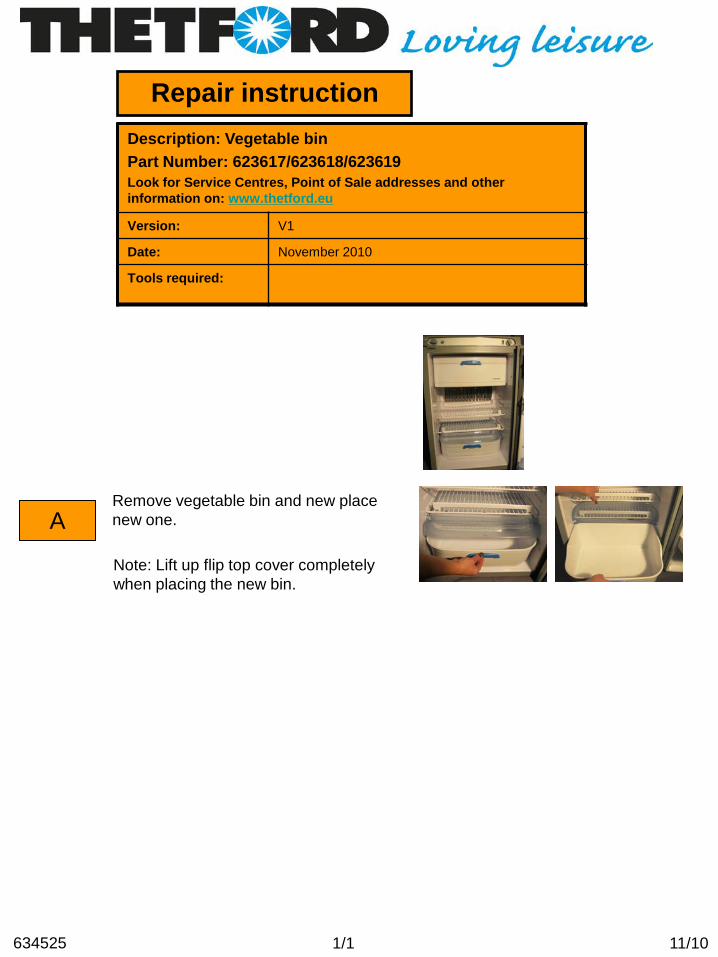
Description: Vegetable bin Part Number: 623617/623618/623619 Look for Service Centres, Point of Sale addresses and other information on: www.thetford.eu
Version: V1
Date: November 2010
Tools required:
1/1 11/10 634525
Note: Lift up flip top cover completely when placing the new bin.
Remove vegetable bin and new place new one.
Repair instruction
A
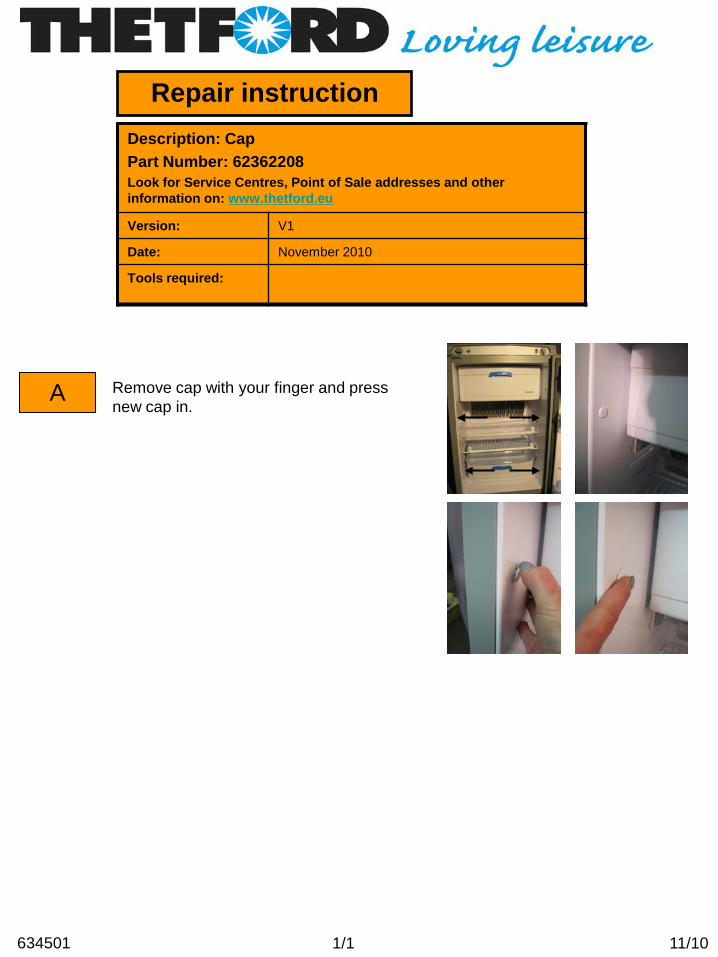
Description: Cap Part Number: 62362208 Look for Service Centres, Point of Sale addresses and other information on: www.thetford.eu
Version: V1
Date: November 2010
Tools required:
Remove cap with your finger and press new cap in.
1/1 11/10 634501

Repair instruction
A
B
C
Description: Clip shelf large Part Number: 62362508/62362608 Look for Service Centres, Point of Sale addresses and other information on: www.thetford.eu
Version: V1
Date: November 2010
Tools required:
Hold shelf with one hand, push up shelf clip with your finger and simoltaniously lift shelf up.
D
1/1 11/10 634503
Replace shelf in desired position on the left side. Lower shelf on the right side to the same height. Push the clip down into the recess.
Press new clip in and make sure that the nodge on te shelf matches the hole in the clip.
Remove shelf from refrigerator and push clip of the shelf.

Repair instruction
A
B
Description: Bottom latch small Part Number: 62400127 Look for Service Centres, Point of Sale addresses and other information on: www.thetford.eu
Version: V1
Date: November 2010
Tools required:
1/1 11/10 634532
Pull bottom latch in direction of the door and replace.
Open door and turn bottom latch completely inwards.

Repair instruction
A
B
Description: Interior light cover Part Number: 624002 Look for Service Centres, Point of Sale addresses and other information on: www.thetford.eu
Version: V1
Date: November 2010
Tools required:
1/1 11/10 634518
Press new cover in.
Push in the 2 clips on the side of the cover, and remove cover.

Repair instruction
A
B
Description: Interior light bulb Part Number: 624003 Look for Service Centres, Point of Sale addresses and other information on: www.thetford.eu
Version: V1
Date: November 2010
Tools required:
C
1/1 11/10 634519
Press new light bulb and cover in.
Push in the 2 clips on the side of the cover, and remove cover.
Remove light bulb fitting.

Repair instruction
A
B
Description: Combustion flap Part Number: 624020/624021 Look for Service Centres, Point of Sale addresses and other information on: www.thetford.eu
Version: V1
Date: November 2010
Tools required:
1/1 11/10 634535
Bend foam strips (4x) in correct position.
Remove protective layer from tape, and attach combustion flap on top rear of refrigerator.

Repair instruction
A
B
C
Description: Screw / Speednut insulation cover Part Number: 624026/624027 Look for Service Centres, Point of Sale addresses and other information on: www.thetford.eu
Version: V1
Date: November 2010
Tools required: Spanner
Push speed nut over insulation cover, make sure the holes line up.
1/1 11/10 634511
Place the screw and tighten with spanner
Position the insulation cover on top of the burner box, lining up the holes in the burner box and the speednut.

Repair instruction
A
B
Description: Glass fuse Part Number: 624030 Look for Service Centres, Point of Sale addresses and other information on: www.thetford.eu
Version: V1
Date: November 2010
Tools required: Torx T-10 screwdriver, Philips screwdrive
C
1/1 11/10 634534
Remove 2 screws from strain relief on power board housing, and remove cover.
Remove 2 screws on side attaching the power board housing to the refrigerator.
Remove 4 screws from black cover on power board housing.
Replace glass fuse. D

Repair instruction
A
B
Description: Shelf food retainer Part Number: 624456-08 Look for Service Centres, Point of Sale addresses and other information on: www.thetford.eu
Version: V1
Date: November 2010
Tools required:
1/1 11/10 634529
Place new shelf food retainer and slide clip underneath the shelf wire. Bend shelf food retainer on other side to connect it to the shelf.
Tilt shelf food retainer backwards onto the shelf. Bend shelf food retainer to release it from the shelf.

Repair instruction
A
Description: Cabinet side seal Part Number: 624476/624477/624478 Look for Service Centres, Point of Sale addresses and other information on: www.thetford.eu
Version: V1
Date: November 2010
Tools required:
1/1 11/10 634536
Note: closed side of seal should point backwards.
Remove protective layer from tape, and attach side seal to side rear end of refrigerator.
Repair instruction
A
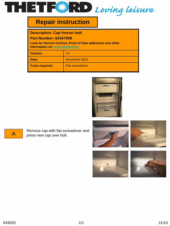
Description: Cap freezer bolt Part Number: 62447908 Look for Service Centres, Point of Sale addresses and other information on: www.thetford.eu
Version: V1
Date: November 2010
Tools required: Flat screwdriver
Remove cap with flat screwdriver and press new cap over bolt.
1/1 11/10 634502

Repair instruction
A
B
Description: Storage strap Part Number: 624679-07 Look for Service Centres, Point of Sale addresses and other information on: www.thetford.eu
Version: V1
Date: November 2010
Tools required:
1/1 11/10 634516
Push new storage strap onto the hinge pin.
Pull latch back and pull up storage strap to remove it from hinge pin.

Repair instruction
A
B
Description: Hinge freezer door Part Number: 624680-08 Look for Service Centres, Point of Sale addresses and other information on: www.thetford.eu
Version: V1
Date: November 2010
Tools required: Philips screwdriver
C
1/1 11/10 634530
Place freezer door in front of freezer cabinet, pushing it up and inwards, (against the tension of the springs in the hinges), place screws back.
Remove both hinges by taking out the 2 screws
Remove 2 screws attaching the freezer door hinges to the bottom of the freezer cabinet. Remove freezer door.

Description: Displayboard LCD Part number: 626972 Look for Service Centres, Point of Sale addresses and other information on: www.thetford.eu
Version:
Date: November 2010
Tools required: Cross Head Screwdriver,
Repair instruction
A
B
C
When exchanging the Display Board there is no need to remove the fridge however we do advise to isolate the fridge from the mains and 12v supply
Remove the oval perspex display by using a small flat screwdriver. Push the screwdriver behind the on/off button and pull forward
Once the first couple of clips have been released the overlay simply pops out
1/3 11/10 634507

D
E
F
Now the overlay has been removed you will see two holes in the grey control board housing.
Fully remove the two screws, one found at the bottom of each hole
The grey control board housing can now be removed taking care not to pull to far from the fridge as the cable is still attached
G
H
Looking inside the control board housing from the back you will notice the LCD display is held in by two clips
Simply hold the clips back and remove the display
2/3 11/10 634507

I Unclip the white wiring loom from the display board by holding the black plug, this way the wiring loom shouldn’t get damaged
J
K
L
Replace the display board into the control board housing ensuring the holes sit over the lugs and the clips are firmly back in place
Replace the control board housing taking care as not to trap any of the wires before screwing it back in place
Re-attach the overlay by clipping back in place. The fridge can now be reconnected to the electricity supply and tested
3/3 11/10 634507
Repair instruction
A
B
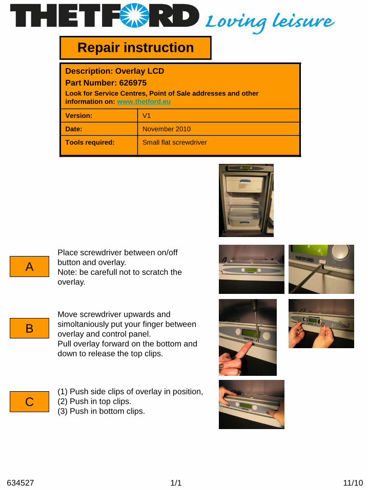
Description: Overlay LCD Part Number: 626975 Look for Service Centres, Point of Sale addresses and other information on: www.thetford.eu
Version: V1
Date: November 2010
Tools required: Small flat screwdriver
C
1/1 11/10 634527
(1) Push side clips of overlay in position, (2) Push in top clips. (3) Push in bottom clips.
Move screwdriver upwards and simoltaniously put your finger between overlay and control panel. Pull overlay forward on the bottom and down to release the top clips.
Place screwdriver between on/off button and overlay. Note: be carefull not to scratch the overlay.

Repair instruction
A
B
Description: Latch V2Part Number: 626985-07/27Look for Service Centres, Point of Sale addresses and other information on: www.thetford.eu
Version: V2
Date: March 2012
Tools required: Torx T-10 , Cross headed screw driver
Remove 2 screws and replace latch.
1/1 03/12634514
Remove 2 screws and replace strike plate.

Repair instruction
A
B
Description: Storage strap V2 Part Number: 62698607-90 Look for Service Centres, Point of Sale addresses and other information on: www.thetford.eu
Version: V1
Date: November 2010
Tools required:
Turn storage strap outwards, and pull it up.
1/1 11/10 634512
Place new storage strap and push it in position

Repair instruction
A
B
Description: Blade fuse Part Number: 626996/626998/624028/624029 Look for Service Centres, Point of Sale addresses and other information on: www.thetford.eu
Version: V1
Date: November 2010
Tools required: Torx T-10 screwdriver, Philips screwdriver
C
1/1 11/10 634533
Remove 2 screws from strain relief on power board housing, and remove cover.
Remove 2 screws on side attaching the power board housing to the refrigerator.
Remove 4 screws from black cover on power board housing.
D There are 3 fuses on the power board. Check the fuses, and replace the blown fuse.

Repair instruction
A
B
C
Description: Flue exhaust long/short Part Number: 624480/627008 Look for Service Centres, Point of Sale addresses and other information on: www.thetford.eu
Version: V1
Date: November 2010
Tools required: Spanner
Loosen clamp screw.
1/1 11/10 634513
Place new flue exhaust and tighten the clamp screw by hand. Replace the refrigerator in the vehicle, position flue exhaust as shown in drawing. Tighten the clamp screw. Note: for further instructions we advise to read our installation manual.
Remove flue exhaust from refrigerator by pulling it upwards.

Repair instruction
A
B
C
Description: Interior light switch Part Number: 629722 Look for Service Centres, Point of Sale addresses and other information on: www.thetford.eu
Version: V1
Date: November 2010
Tools required: Cross Head Screwdriver,
On the N180 fridge the reed switch for the interior light is situated in the bottom right hand corner of the cabinet beneath the lining, therefore the fridge needs to be disconnected and laid down in order to change it. This needs to be done by a qualified competent gas engineer
Once the fridge has been laid down you will see an envolope flap towards the front of the fridge, remove the tape holding the cardboard in place to reveal the wiring loom
The reed switch is located at the right hand side and has 2 black wires going to it
D Simply unclip the existing faulty reed switch
1/2 11/10 634508

E
F
Chase the wiring back to the plug and unclip the reed switch ensuring you pull the white male and female plugs and not the wires
Connect the new Reed switch
G
H
I
Once the new part has been reconnected to the wiring loom clip the reed switch back into place
Once it is back in place ensure the reed switch is pushed up as far as it will go,
Replace all the wiring into the chanel and tape the cardboard back in place before re-installing the fridge.
2/2 11/10 634508
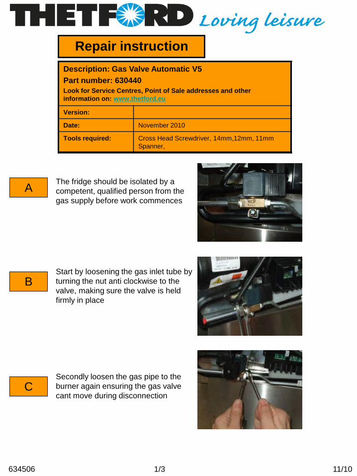
Description: Gas Valve Automatic V5 Part number: 630440 Look for Service Centres, Point of Sale addresses and other information on: www.thetford.eu
Version:
Date: November 2010
Tools required: Cross Head Screwdriver, 14mm,12mm, 11mm Spanner,
Repair instruction
A
B
C
The fridge should be isolated by a competent, qualified person from the gas supply before work commences
Start by loosening the gas inlet tube by turning the nut anti clockwise to the valve, making sure the valve is held firmly in place
Secondly loosen the gas pipe to the burner again ensuring the gas valve cant move during disconnection
1/3 11/10 634506

D
E
F
The gas inlet tube can now be removed from the gas valve
Completely unscrew the fastening that holds the burner pipe to the gas valve
Remove the plug from the valve by undoing the screw on the front
G
H
Remove the screw thats holding the gas valve to the galvenised bracket
The gas valve can now be removed by sliding it away from the burner tube
2/3 11/10 634506
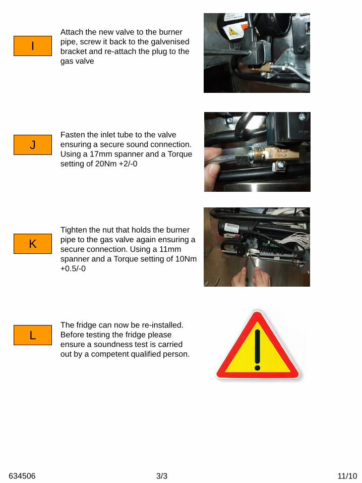
I Attach the new valve to the burner pipe, screw it back to the galvenised bracket and re-attach the plug to the gas valve
J
K
L
Fasten the inlet tube to the valve ensuring a secure sound connection. Using a 17mm spanner and a Torque setting of 20Nm +2/-0
Tighten the nut that holds the burner pipe to the gas valve again ensuring a secure connection. Using a 11mm spanner and a Torque setting of 10Nm +0.5/-0
The fridge can now be re-installed. Before testing the fridge please ensure a soundness test is carried out by a competent qualified person.
3/3 11/10 634506

Description: Gas assembly / Burner Part number: 631248/631249/623019/623058 Look for Service Centres, Point of Sale addresses and other information on: www.thetford.eu
Version: V1
Date: November 2010
Tools required: Cross Head Screwdriver, 14mm,12mm, 11mm Spanner
Repair instruction
A
B
C
Before work commences please ensure the fridge is isolated from the gas supply, this must be carried out by a competent qualified person, and that you have good access to the back of the fridge
Start by removing the two 7mm screws from the burner box housing
Remove the cover taking care not to damage electrode lead
1/3 11/10 634505

D
E
F
Remove the one screw that is holding the burner to the burner box
Remove the plug from the gas valve by undoing the screw and pulling away.
Undo the screw which is holding the valve to the galvanised bracket
Please be aware that on certain models the gas inlet tube may need to be removed
G
H
The whole assembly can now be removed by sliding the burner out of the burner box housing
When inserting the new assembly please ensure that the burner sits back in the slot in the burner box
2/3 11/10 634505

I The valve can now be re-attached to the galvenised bracket and the black plug screwed onto the new valve making sure the seal is correctly in place, where necessary re-attach the inlet tube using a 17mm Spanner and a torque setting of 20Nm +2/-0
J
K
Secure the burner to the housing by replacing the screw ensuring there is no movement from the burner
The burner box cover can now be put back in place, making sure the electrode lead is free from kinks and passing through the black shroud
L The fridge can now be re-installed. Before testing the fridge please ensure a soundness test is carried out by a competent qualified person.
3/3 11/10 634505

Repair instructionDescription: Power Board HousingPart Number: 634420/634421/634422/634423Look for Service Centres, Point of Sale addresses and other information on: www.thetford.eu
Version: V1
Date: December 2010
Tools required: Torx T10, Philips screwdriver, 7mm nut spinner
A
B
C
If the fridge needs to be removed pleasemake sure this is done by a qualifiedcompetent person. Isolate the fridge fromall power sources. Once you have access to the power bored start by removing the 3 torque screws holding the cover in place.
Once the cover has been removed, the mains and 12v connections can bedisconnected *.
The power board can now be removed byundoing the two 7mm nut screws, oneeach side of the board, please note thatthe gas solenoid valve may need to berotated to access one of the screws.
* Please note, the colour of the 12v cables illustrated may not match those of the fridge you are working on.
The power board and housingcan now be pulled clear of the fridge for ease of access.
D
1/4 12/10633925
NOTE: make sure to wear ESD protection/ f.i. ESD bracelet

Now you have clear access to the board remove the 3 torque screws from the top of the board housing.
Using a flat headscrewdriver undo the 2 clips holding the top of power board cover in place.
The power board lid can nowbe removed giving you access to the circuit boards and wiring beneath.
To disconnect the power board start by removing the earth bar and Mainselement.
E
F
G
H
IAlso remove the 12v element connections and the white wiringharness taking care to pull the black socket and not the wires.
2/4 12/10633925
J And finally the electrode lead andgas valve leads can be removed.

KThe replacement board can now bereconnected connecting the wires in reverse as above.
L
M
N
Install heater cables, spark electrode, solenoid cable and earth cables onsame position.
Place strainrelief. Torque 1 Nm.
Make sure also white wire harnessis installed.
O Place cover and mount cover with2 screws to bottom. Torque 1 Nm.
P Place tywrap around white wireharness & heater cables.
3/4 12/10633925
Q Install power board housing toback of fridge by 2 screws.Torque 2 Nm.

R
S
4/4 12/10633925
T
Pull cables away from burner andfix them with a tywrap to tube.
Install power cables.Attention: Make sure the sleevesare placed in the strainrelief asindicated in picture.
Place strainrelief by mounting2 screws. Torque 1 Nm.
U
V
Place lid by sliding it into thepower board housing and fixit by 1 screw. Torque 1 Nm.
Assemble solenoid cable androtate. Torque handtight.
The fridge can now be re-installed. Before testing the fridge pleaseensure a soundness test is carriedout by a competent qualified person.

January 2010Date:
Philips screwdriver (or drill) and a small flat head screwdriver
Tools required:
Version:
HingesLook for Service Centres, Point of Sale addresses and other information on: www.thetford.eu
Fridge exchange instruction
A
As the door from the original fridge is to be used, the correct hinges must be fitted. If the hinges on the original fridge differ from the replacement then they will have to be swapped over.
On fridge freezers the centre bracket will also need swapping if it differs from the original. These brackets on the new style are handed.
Note: instruction is for adapting fridge from left to right and/or moved hinge configuration.
New style centrebracket forleft hand fridges.
New style centrebracket forright hand fridges.
Old style hinge
New style hinge
1/3 01/10

In case of LCDC
To access the top hinge simply undo the 2 Philips screws in the control assembly (there are 3 holes but the centre one has a location pin).
If the hand of the fridge is to be changed the control assembly has to be rotated to allow the hinge to fit through the cut out. To do this the plug for the display panel and reed switch will need disconnecting.
B In case of V85
To access the hinges remove the 2 control knobs and the 2 screws on the black cover.
Remove the 3 screw which secure the fascia.
Once all screws have been removed the fascia can be pulled forward to allow easy access to the top hinge.
2/3 01/10

H
GIf fitted, the bottom travel catch will need to be removed from the original fridge. This can be taken off by removing the 3 Philips screws. The new fridge will be pre drilled to accept this part.
Warranty fridges are supplied with grey or black caps which are to be put into any visible holes which have not been used once the new fridge has been prepared.
D
E
F
All warranty fridges are pre drilled to accept left or right hand options. The holes are also the same for the new and old hinges.
Remove the 3 screws from both the bottom and top hinge using a Philips screwdriver.
If you have to swap the centre bracket you will have to take off the display panel (see separate instructions) then remove the 4 Philips screws. Ensure the correct hand is fitted if using the new style.
3/3 01/10

631151/0707
Manufactured by:Thetford BVP.O. box 1694870 AD Etten-LeurThe NetherlandsTel.: +31 (0) 76 504 22 00E-mail: [email protected]
When to use a vent cover?Wann sollte eine Winterabdeckung benutzt werden?Quand utiliser les "Caches-hiver" ?Wanneer moet u een vent cover gebruiken?Quando usare un coperchio invernale?¿Cuándo se utiliza un cubierta para el respiradero?När ska ventilens täcklucka användas?
<8°C
Disassemble / Auseinanderbauen / Dépose / Demonteren /Smontaggio / Desmontar / Montera bort
Assemble / Zusammenbauen / Pose / Monteren / Montaggio /Montar / Montera
1
2
3
4