Embed Size (px)
Citation preview

1
Preface
This Repair Manual is designed to facilitate competent repair of the engines listed herein.
The pictures and relevant descriptions show typical work that may not always be applicable to the engine inhand, which nevertheless does not mean that they are not correct. In such cases the repair work is to beplanned and carried out in a similar way.
The expert knowledge necessary for handling Diesel engines was taken for granted when this publicationwas compiled.
Any repair of components such as injection pump, alternator etc. ought to be left to our or the manufactur-er’s service department.
MAN Nutzfahrzeuge AktiengesellschaftNuremberg Works
We reserve the right to make technical modifications in the course of further development.
1999 MAN Nutzfahrzeuge AktiengesellschaftReprinting, copying or translation, even in the form of excerpts, is forbidden without the written permissionof MAN. MAN expressly reserves all rights in accordance with the law on copyright.
MTDA / 05.99 51.99493-8428
Contents
2
PageSafety instructions 5 . . . . . . . . . . . . . . . . . . . . . . . . . . . . . . . . . . . . . . . . . . . . . . . . . . . . . . . General information on the overhaul of engines 8 . . . . . . . . . . . . . . . . . . . . . . . . . . . . . . Trouble shooting table 9 . . . . . . . . . . . . . . . . . . . . . . . . . . . . . . . . . . . . . . . . . . . . . . . . . . . . Engine views, D 2866 LE401 16 . . . . . . . . . . . . . . . . . . . . . . . . . . . . . . . . . . . . . . . . . . . . . . Schematic diagram of engine lubrication system 20 . . . . . . . . . . . . . . . . . . . . . . . . . . . . . Schematic diagram of fuel system 21 . . . . . . . . . . . . . . . . . . . . . . . . . . . . . . . . . . . . . . . . . Schematic diagram of cooling system 22 . . . . . . . . . . . . . . . . . . . . . . . . . . . . . . . . . . . . . .
Fuel systemChecking and adjusting start of fuel delivery 23 . . . . . . . . . . . . . . . . . . . . . . . . . . . . . . . . . Removing and installing injection pump 27 . . . . . . . . . . . . . . . . . . . . . . . . . . . . . . . . . . . . . Removing and installing fuel injectors 30 . . . . . . . . . . . . . . . . . . . . . . . . . . . . . . . . . . . . . . Checking and repairing fuel injectors 32 . . . . . . . . . . . . . . . . . . . . . . . . . . . . . . . . . . . . . . . Cleaning fuel prefilter 35 . . . . . . . . . . . . . . . . . . . . . . . . . . . . . . . . . . . . . . . . . . . . . . . . . . . . . Changing fuel filter cartridges 36 . . . . . . . . . . . . . . . . . . . . . . . . . . . . . . . . . . . . . . . . . . . . .
Cooling systemDraining and filling with coolant 37 . . . . . . . . . . . . . . . . . . . . . . . . . . . . . . . . . . . . . . . . . . . . Removing and installing thermostat 39 . . . . . . . . . . . . . . . . . . . . . . . . . . . . . . . . . . . . . . . . Removing and installing water pump 40 . . . . . . . . . . . . . . . . . . . . . . . . . . . . . . . . . . . . . . . Repairing water pump 42 . . . . . . . . . . . . . . . . . . . . . . . . . . . . . . . . . . . . . . . . . . . . . . . . . . . . Repairing water pump 41 . . . . . . . . . . . . . . . . . . . . . . . . . . . . . . . . . . . . . . . . . . . . . . . . . . . . Removing and attaching expansion tank 45 . . . . . . . . . . . . . . . . . . . . . . . . . . . . . . . . . . . . Removing and installing heat exchanger 46 . . . . . . . . . . . . . . . . . . . . . . . . . . . . . . . . . . . . Cleaning heat exchanger pipe set 48 . . . . . . . . . . . . . . . . . . . . . . . . . . . . . . . . . . . . . . . . . . Raw water pump 49 . . . . . . . . . . . . . . . . . . . . . . . . . . . . . . . . . . . . . . . . . . . . . . . . . . . . . . . . .
LubricationChanging oil filter 51 . . . . . . . . . . . . . . . . . . . . . . . . . . . . . . . . . . . . . . . . . . . . . . . . . . . . . . . . Removing and installing oil cooler 52 . . . . . . . . . . . . . . . . . . . . . . . . . . . . . . . . . . . . . . . . . . Removing and installing oil pump 53 . . . . . . . . . . . . . . . . . . . . . . . . . . . . . . . . . . . . . . . . . . Oil spray nozzle 57 . . . . . . . . . . . . . . . . . . . . . . . . . . . . . . . . . . . . . . . . . . . . . . . . . . . . . . . . .
Flywheel / Crankshaft sealRemoving and installing vibration damper, changing front crankshaft seal 58 . . . . . . . Removing and installing flywheel, replacing gear ring 62 . . . . . . . . . . . . . . . . . . . . . . . . . Removing and installing crankshaft seal (flywheel end) 64 . . . . . . . . . . . . . . . . . . . . . . . Exchanging bearing race 65 . . . . . . . . . . . . . . . . . . . . . . . . . . . . . . . . . . . . . . . . . . . . . . . . . Crankshaft seals 66 . . . . . . . . . . . . . . . . . . . . . . . . . . . . . . . . . . . . . . . . . . . . . . . . . . . . . . . . .
Intake / exhaust systemRemoving and installing intake manifold 67 . . . . . . . . . . . . . . . . . . . . . . . . . . . . . . . . . . . . Turbocharger, trouble shooting 70 . . . . . . . . . . . . . . . . . . . . . . . . . . . . . . . . . . . . . . . . . . . . Checking the charge-air pressure 72 . . . . . . . . . . . . . . . . . . . . . . . . . . . . . . . . . . . . . . . . . . Removing and installing turbocharger 73 . . . . . . . . . . . . . . . . . . . . . . . . . . . . . . . . . . . . . . Checking axial and radial play of turbocharger rotor shaft 75 . . . . . . . . . . . . . . . . . . . . . Exchanging waste gate 76 . . . . . . . . . . . . . . . . . . . . . . . . . . . . . . . . . . . . . . . . . . . . . . . . . . . Removing and installing intercooler 77 . . . . . . . . . . . . . . . . . . . . . . . . . . . . . . . . . . . . . . . .
Contents
3
Cylinder headRemoving and installing cylinder head 79 . . . . . . . . . . . . . . . . . . . . . . . . . . . . . . . . . . . . . . Setting valve clearance 84 . . . . . . . . . . . . . . . . . . . . . . . . . . . . . . . . . . . . . . . . . . . . . . . . . . . Disassembling and assembling rocker arms 86 . . . . . . . . . . . . . . . . . . . . . . . . . . . . . . . . . Removing and installing valves 87 . . . . . . . . . . . . . . . . . . . . . . . . . . . . . . . . . . . . . . . . . . . . Removing and installing valve guides 90 . . . . . . . . . . . . . . . . . . . . . . . . . . . . . . . . . . . . . . . Replacing valve seat insert 91 . . . . . . . . . . . . . . . . . . . . . . . . . . . . . . . . . . . . . . . . . . . . . . . . Reworking valve seat 93 . . . . . . . . . . . . . . . . . . . . . . . . . . . . . . . . . . . . . . . . . . . . . . . . . . . . . Refacing valves 96 . . . . . . . . . . . . . . . . . . . . . . . . . . . . . . . . . . . . . . . . . . . . . . . . . . . . . . . . . Checking compression 97 . . . . . . . . . . . . . . . . . . . . . . . . . . . . . . . . . . . . . . . . . . . . . . . . . . .
Valve timingRemoving and installing timing case 98 . . . . . . . . . . . . . . . . . . . . . . . . . . . . . . . . . . . . . . . . Removing and installing camshaft, exchanging camshaft bearing 99 . . . . . . . . . . . . . . Checking valve timing 101. . . . . . . . . . . . . . . . . . . . . . . . . . . . . . . . . . . . . . . . . . . . . . . . . . . .
Crankgear, pistonsRemoving and installing crankshaft 102. . . . . . . . . . . . . . . . . . . . . . . . . . . . . . . . . . . . . . . . Removing and installing piston with connecting rod 105. . . . . . . . . . . . . . . . . . . . . . . . . . . Detaching piston from and attaching to connecting rodchecking - changing connecting rod 108. . . . . . . . . . . . . . . . . . . . . . . . . . . . . . . . . . . . . . . . Removing, installing and changing piston rings 110 . . . . . . . . . . . . . . . . . . . . . . . . . . . . . . Replacing cylinder liners 112 . . . . . . . . . . . . . . . . . . . . . . . . . . . . . . . . . . . . . . . . . . . . . . . . . . Measuring piston protrusion 115 . . . . . . . . . . . . . . . . . . . . . . . . . . . . . . . . . . . . . . . . . . . . . . . Removing and installing starter 116 . . . . . . . . . . . . . . . . . . . . . . . . . . . . . . . . . . . . . . . . . . . . V-belts 117 . . . . . . . . . . . . . . . . . . . . . . . . . . . . . . . . . . . . . . . . . . . . . . . . . . . . . . . . . . . . . . . . . . Coolant level probe 119 . . . . . . . . . . . . . . . . . . . . . . . . . . . . . . . . . . . . . . . . . . . . . . . . . . . . . .
AttachmentsSpecial tools 124. . . . . . . . . . . . . . . . . . . . . . . . . . . . . . . . . . . . . . . . . . . . . . . . . . . . . . . . . . . .
Index 135. . . . . . . . . . . . . . . . . . . . . . . . . . . . . . . . . . . . . . . . . . . . . . . . . . . . . . . . . . . . . . . . . . . . .

Safety instructions
4
General information
This brief overview summarises important instructions and is structured into areas of main concern in orderto impart the knowledge necessary to prevent accidents involving injury to persons, damage to the engineor other property and harm to the environment. Additional notes are included in the operator’s manual forthe engine.
Important: If despite all safety precautions an accident occurs as a result of contact with caustic acids,penetration of fuel into the skin, scalding with hot oil, anti-freeze splashes into the eyes etc, consult a doc-tor immediately!
1. Instructions for preventing accidents with injury to persons
Checks, setting jobs and repair work must be carried out by authorised skilled personnel only.
D When carrying out maintenance and repair work, ensure that the engine cannot be ac-cidentally started from the bridge by unauthorised persons.
D The engine must be started and operated by authorised personnel only.
D When the engine is running, do not get too close to revolving components. Wear tight-fitting working clothes.
D Do not touch hot engine with bare hands: risk of burning yourself.
ËË
D Keep engine vicinity, ladder and steps free of oil and grease. Accidents resulting fromslipping may have serious consequences.
D Work only with tools that are in good condition. Worn spanners slip: risk of injuries.
D Persons must not stand under an engine suspended from a crane hook. Keep liftinggear in good order.
D Open coolant circuit only after the engine has cooled down. If opening the coolant cir-cuit while the engine is hot is unavoidable, observe the instructions in the chapter”Maintenance and care” in the Operator’s Manual.
D Neither retighten nor open pressurised pipelines and hoses (lube oil circuit, coolant cir-cuit and downstream hydraulic oil circuit if fitted): risk of injuries resulting from emergingfluids.
Safety instructions
5
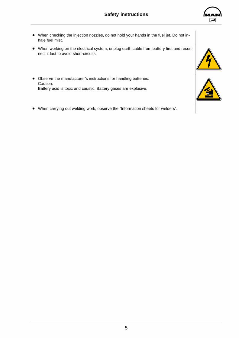
D When checking the injection nozzles, do not hold your hands in the fuel jet. Do not in-hale fuel mist.
D When working on the electrical system, unplug earth cable from battery first and recon-nect it last to avoid short-circuits.
D Observe the manufacturer’s instructions for handling batteries.Caution:Battery acid is toxic and caustic. Battery gases are explosive.
D When carrying out welding work, observe the ”Information sheets for welders”.

Safety instructions
6
2. Instructions for preventing damage to the engine and premature wear
D Prior to repairing the engine, clean it thoroughly. Ensure that dirt, sand or foreign matter willnot get into the engine during repair work.
D In the event of operational faults immediately identy the cause and rectify to prevent more serious dam-age.
D Always use genuine MAN parts only. Installation of ”equally” good parts from other suppliers may causesevere damage for which the workshop carrying out the work is responsible.
D Never operate the engine while it is dry, i.e. without lubricant or coolant. Use a suitable label to mark engines not ready for operation.
D Only use operating materials (fuel, engine oil, antifreeze and anticorrosion agents) approved by MAN.Ensure that everything is kept clean. Diesel fuel must be free of water.
D Do not fill up with engine oil above the max. notch on the dipstick. Do not exceed the engine’smaximum permissible operating inclination.Non–compliance with these instructions may cause severe engine damage.
D Control and monitoring devices (charge check, oil pressure, coolant temperature) must work faultlessly.
D Observe the instructions for operating the alternator; see chapter ”Commissioning and operation” in theOperator’s Manual.
3. Instructions for preventing environmental damage
Engine oil and filter cartridges and elements, fuel/fuel filters
D Take old oil to an old oil disposal point only.
D Ensure without fail that oil and Diesel fuel will not get into the sewerage system or the ground.Caution:Danger of contaminating potable water!
D Treat filter elements and cartridges as special waste.
Coolant
D Treat undiluted anticorrosion and/or antifreeze agents as special waste.
D The regulations of the relevant local authorities are to be observed for the disposal of spent coolants.
Safety instructions
7
4. Instructions for handling used engine oil *
Prolonged or repeated contact of any kind of engine oil with the skin causes the skin to degrease, whichmay result in dryness, irritation or inflammation. Old engine oil also contains hazardous substances whichin animal experiments have caused skin cancer. Handling old engine oil does not pose any health hazard ifthe basic safety and hygiene related regulations are observed.
Health and safety regulations:
D Avoid prolonged, excessive or repeated contact of old engine oil with the skin.
D Use a suitable skin protection agent or wear protective gloves.
D Clean the skin that has been in contact with engine oil.– Wash yourself thoroughly with soap and water. A nailbrush is an effective aid.– Special hand cleaning agents facilitate cleaning soiled hands.– Do not use petrol, Diesel fuel, gas oil, fluxes or solvents as cleaning agents.
D After washing apply moisturising handcream to your skin.
D Change oil-soaked clothes and shoes.
D Do not put any oil-soaked cloths into pockets.
Pay meticulous attention to the proper disposal of old engine oil. – Old oil is a water hazard –
Therefore, do not pour any old oil into the ground, the drains or the sewerage system. Any violation of thisrule is punishable.
Collect and dispose of old engine oil properly. For information concerning collection points, contact seller,supplier or the local authorities.
∗ Based on the ”Merkblatt für den Umgang mit gebrauchtem Motorenöl”
(Notes on how to handle old engine oil).
General information on the overhaul of engines
8
Very different factors have an influence on the life expectancy of an engine. For this reason it is not pos-sible to give certain predetermined numbers of operating hours for basic overhauls.
Regular interim inspections and overhauls frequently carried out on large engines (e.g. on those from MANAugsburg) are generally not necessary on MAN Diesel engines from the MAN Nuremberg works.
In our opinion, opening an engine or carrying out a basic overhaul is not appropriate as long as the engineachieves good compression values and the following operating values measured and recorded and havenot changed significantly since commissioning:
D Charge-air pressure
D Exhaust-gas temperature
D Coolant and lube-oil temperature
D Oil pressure and oil consumption
D Formation of smoke
The following criteria have a major influence on the life expectancy of an engine:
D Correct output setting according to the type of operation.
D Expert installation in accordance with the installation instructions.
D Inspection of the installation by authorized personnel.
D Regular maintenance as per maintenance plan
D Selection and quality of lube oil, fuel and coolant as specified in the publication”Fuels, Lubricants, Coolants for Industrial and Marine Diesel Engines”.
Trouble shooting table
9
Faults and possible causes
We recommend
Repair work is to be considered complete only after the damage which has occurred and the possible
causes have been eliminated. Ascertaining the causes of damage is frequently more difficult than eliminat-
ing the damage caused. For this reason we recommend you have the operational fault exactly described to
you before removal or disassembly work is commenced. Then, track down the probable causes by asking
specific questions, examining and eliminating these causes one by one with the aid of the table and your
own experience. This helps to reduce repairs to those necessary and counter complaints about ”prema-
ture” exchange of parts and expensive working and downtimes.
Remark:
The subsequent list is meant to be a memory aid so that no causes of damage will be overlooked in the
elimination of faults. The precondition for this, however, is that you are familiar with the Repair Manual for
the engine and the relevant Operating Instructions as well as the publication ”Fuels, Lubricants, Coolants
for Industrial and Marine Diesel Engines”.
Trouble shooting table
10
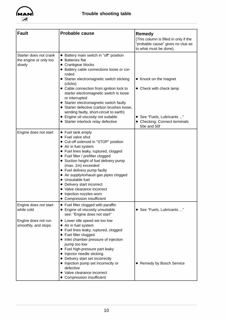
Fault Probable cause Remedy(This column is filled in only if the”probable cause” gives no clue asto what must be done).
Starter does not crankthe engine or only tooslowly
D Battery main switch in ”off” positionD Batteries flatD Crankgear blocksD Battery cable connections loose or cor-
rodedD Starter electromagnetic switch sticking
(clicks)D Cable connection from ignition lock to
starter electromagnetic switch is looseor interrupted
D Starter electromagnetic switch faultyD Starter defective (carbon brushes loose,
winding faulty, short-circuit to earth)D Engine oil viscosity not suitableD Starter interlock relay defective
D Knock on the magnet
D Check with check lamp
D See ”Fuels, Lubricants ...”D Checking: Connect terminals
50e and 50f
Engine does not start D Fuel tank emptyD Fuel valve shutD Cut-off solenoid in “STOP” positionD Air in fuel systemD Fuel lines leaky, ruptured, cloggedD Fuel filter / prefilter cloggedD Suction height of fuel delivery pump
(max. 1m) exceededD Fuel delivery pump faultyD Air supply/exhaust gas pipes cloggedD Unsuitable fuelD Delivery start incorrectD Valve clearance incorrectD Injection nozzles wornD Compression insufficient
Engine does not startwhile cold
D Fuel filter clogged with paraffinD Engine oil viscosity unsuitable
see: ”Engine does not start”D See ”Fuels, Lubricants ...”
Engine does not runsmoothly, and stops
D Lower idle speed set too lowD Air in fuel systemD Fuel lines leaky, ruptured, cloggedD Fuel filter cloggedD Inlet chamber pressure of injection
pump too lowD Fuel high-pressure part leakyD Injector needle stickingD Delivery start set incorrectlyD Injection pump set incorrectly or
defectiveD Valve clearance incorrectD Compression insufficient
D Remedy by Bosch Service
Trouble shooting table
11
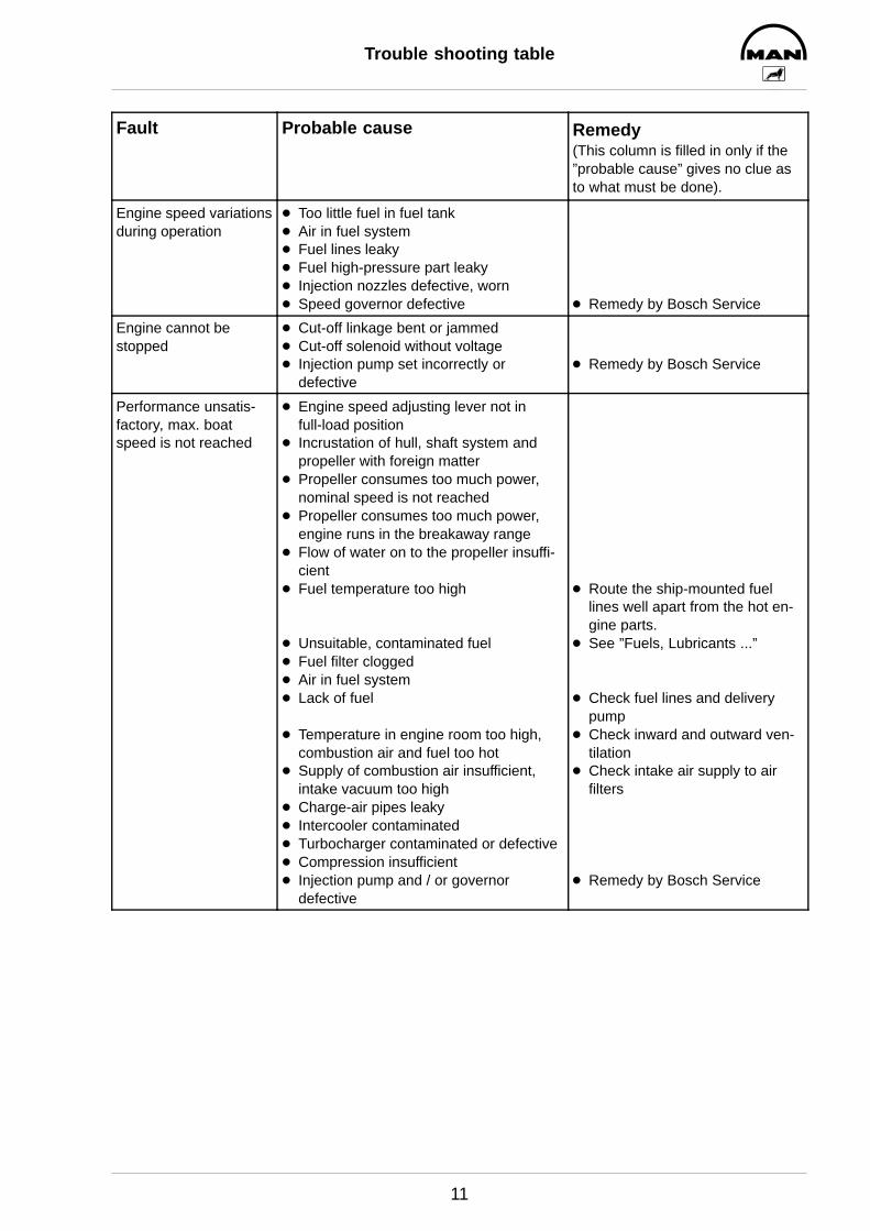
Fault Remedy(This column is filled in only if the”probable cause” gives no clue asto what must be done).
Probable cause
Engine speed variationsduring operation
D Too little fuel in fuel tankD Air in fuel systemD Fuel lines leakyD Fuel high-pressure part leakyD Injection nozzles defective, wornD Speed governor defective D Remedy by Bosch Service
Engine cannot be stopped
D Cut-off linkage bent or jammedD Cut-off solenoid without voltageD Injection pump set incorrectly or
defectiveD Remedy by Bosch Service
Performance unsatis-factory, max. boatspeed is not reached
D Engine speed adjusting lever not in full-load position
D Incrustation of hull, shaft system andpropeller with foreign matter
D Propeller consumes too much power,nominal speed is not reached
D Propeller consumes too much power,engine runs in the breakaway range
D Flow of water on to the propeller insuffi-cient
D Fuel temperature too high
D Unsuitable, contaminated fuelD Fuel filter cloggedD Air in fuel systemD Lack of fuel
D Temperature in engine room too high,combustion air and fuel too hot
D Supply of combustion air insufficient,intake vacuum too high
D Charge-air pipes leakyD Intercooler contaminatedD Turbocharger contaminated or defectiveD Compression insufficientD Injection pump and / or governor
defective
D Route the ship-mounted fuellines well apart from the hot en-gine parts.
D See ”Fuels, Lubricants ...”
D Check fuel lines and deliverypump
D Check inward and outward ven-tilation
D Check intake air supply to air filters
D Remedy by Bosch Service
Trouble shooting table
12
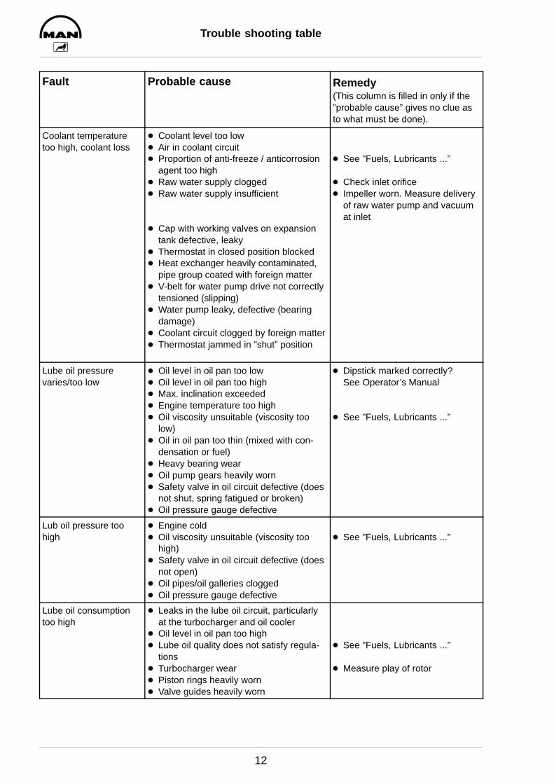
Fault Remedy(This column is filled in only if the”probable cause” gives no clue asto what must be done).
Probable cause
Coolant temperaturetoo high, coolant loss
D Coolant level too lowD Air in coolant circuitD Proportion of anti-freeze / anticorrosion
agent too highD Raw water supply cloggedD Raw water supply insufficient
D Cap with working valves on expansiontank defective, leaky
D Thermostat in closed position blockedD Heat exchanger heavily contaminated,
pipe group coated with foreign matterD V-belt for water pump drive not correctly
tensioned (slipping)D Water pump leaky, defective (bearing
damage)D Coolant circuit clogged by foreign matterD Thermostat jammed in ”shut” position
D See ”Fuels, Lubricants ...”
D Check inlet orificeD Impeller worn. Measure delivery
of raw water pump and vacuumat inlet
Lube oil pressure varies/too low
D Oil level in oil pan too lowD Oil level in oil pan too highD Max. inclination exceededD Engine temperature too highD Oil viscosity unsuitable (viscosity too
low)D Oil in oil pan too thin (mixed with con-
densation or fuel)D Heavy bearing wearD Oil pump gears heavily wornD Safety valve in oil circuit defective (does
not shut, spring fatigued or broken)D Oil pressure gauge defective
D Dipstick marked correctly?See Operator’s Manual
D See ”Fuels, Lubricants ...”
Lub oil pressure toohigh
D Engine coldD Oil viscosity unsuitable (viscosity too
high)D Safety valve in oil circuit defective (does
not open)D Oil pipes/oil galleries cloggedD Oil pressure gauge defective
D See ”Fuels, Lubricants ...”
Lube oil consumptiontoo high
D Leaks in the lube oil circuit, particularlyat the turbocharger and oil cooler
D Oil level in oil pan too highD Lube oil quality does not satisfy regula-
tionsD Turbocharger wearD Piston rings heavily wornD Valve guides heavily worn
D See ”Fuels, Lubricants ...”
D Measure play of rotor

Trouble shooting table
13
Fault Remedy(This column is filled in only if the”probable cause” gives no clue asto what must be done).
Probable cause
Fuel consumption toohigh
D Constant full-load operationD Speed resistance owing to incrustation
of hull, shaft system and propeller withforeign matter
D Poor efficiency of the drive systemD Fuel quality does not satisfy regulationsD Fuel leaks in the systemD High power requirements by additional
units (hydraulic pumps, compressorsetc)
D Delivery start set incorrectlyD Injection pump set incorrectly or defec-
tiveD Valve clearance incorrectD Intake vacuum / exhaust backpressure
too highD Injection nozzles worn
D Adjust propellerD See ”Fuels, Lubricants ...”
D Remedy by Bosch Service
Black smoke D Lack of combustion air, intake vacuumtoo high
D Engine speed reduction owing to thepropeller’s taking up too much power
D Sudden full load after long low load oridling periods
D Air filter contaminatedD Leaks in air pipes downstream of com-
pressorD Diaphragm in wastegate leakyD Intercooler leaky, defectiveD Unsuitable fuelD Turbocharger defectiveD Delivery start set incorrectlyD Injection nozzles defective, cokedD Injection pump set incorrectly or
defectiveD Exhaust backpressure too high
D Check intake air supply to air fil-ters (engine room ventilation)
D See ”Fuels, Lubricants ...”
D Remedy by Bosch Service
Blue smoke D Engine coolant/intake air still too coldD Mainly low-load operationD Piston rings worn or brokenD Valve guides wornD Crankcase breather clogged (overpres-
sure in crankcase)
White smoke D Engine coolant/intake air still too coldD Water evaporates in exhaust gas pipe
during raw water injectionD Delivery start set incorrectlyD Cylinder head gasket leaky/burned
throughD Fuel quality does not satisfy regulationsD Injection nozzles defectiveD Injection pump set incorrectly or
defective
D See ”Fuels, Lubricants ...”
D Remedy by Bosch Service
Trouble shooting table
14
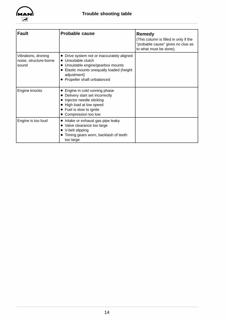
Fault Remedy(This column is filled in only if the”probable cause” gives no clue asto what must be done).
Probable cause
Vibrations, droningnoise, structure-bornesound
D Drive system not or inaccurately alignedD Unsuitable clutchD Unsuitable engine/gearbox mountsD Elastic mounts unequally loaded (height
adjustment)D Propeller shaft unbalanced
Engine knocks D Engine in cold running phaseD Delivery start set incorrectlyD Injector needle stickingD High load at low speedD Fuel is slow to igniteD Compression too low
Engine is too loud D Intake or exhaust gas pipe leakyD Valve clearance too largeD V-belt slippingD Timing gears worn, backlash of teeth
too large
Trouble shooting table
15
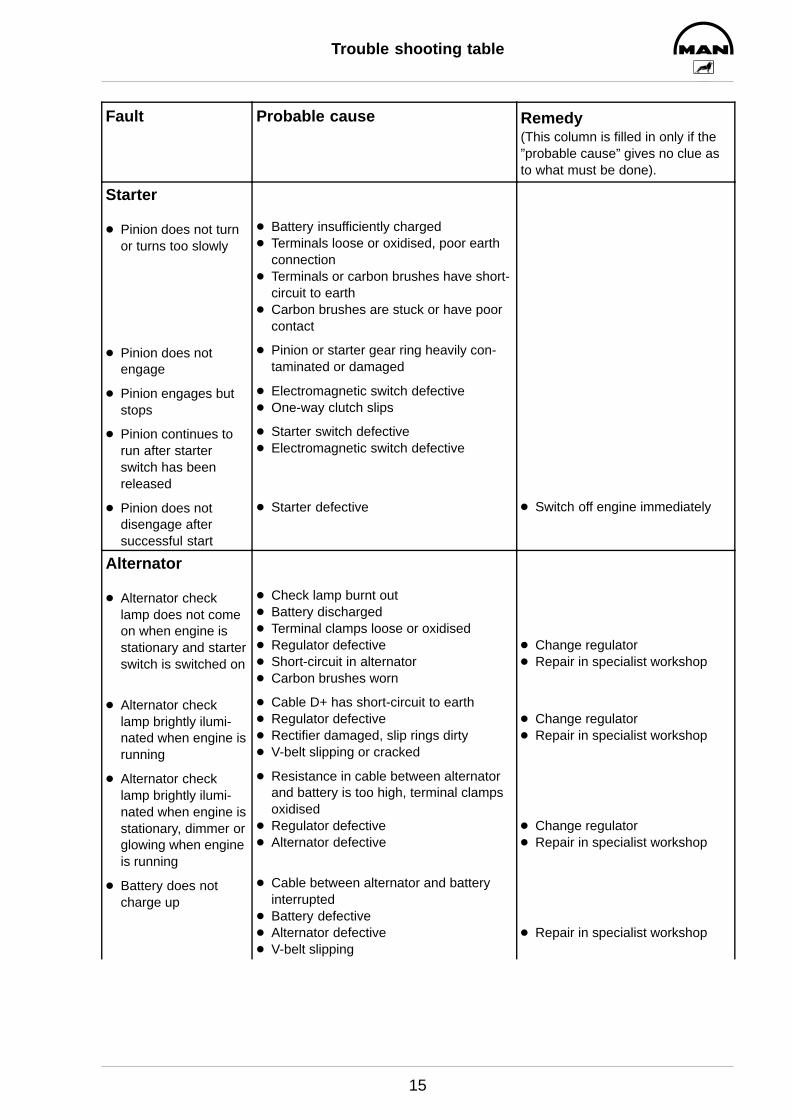
Fault Remedy(This column is filled in only if the”probable cause” gives no clue asto what must be done).
Probable cause
Starter
D Pinion does not turnor turns too slowly
D Pinion does not engage
D Pinion engages butstops
D Pinion continues torun after starterswitch has been released
D Pinion does not disengage after successful start
D Battery insufficiently chargedD Terminals loose or oxidised, poor earth
connectionD Terminals or carbon brushes have short-
circuit to earthD Carbon brushes are stuck or have poor
contact
D Pinion or starter gear ring heavily con-taminated or damaged
D Electromagnetic switch defectiveD One-way clutch slips
D Starter switch defectiveD Electromagnetic switch defective
D Starter defective D Switch off engine immediately
Alternator
D Alternator checklamp does not comeon when engine isstationary and starterswitch is switched on
D Alternator checklamp brightly ilumi-nated when engine isrunning
D Alternator checklamp brightly ilumi-nated when engine isstationary, dimmer orglowing when engineis running
D Battery does notcharge up
D Check lamp burnt outD Battery dischargedD Terminal clamps loose or oxidisedD Regulator defectiveD Short-circuit in alternatorD Carbon brushes worn
D Cable D+ has short-circuit to earthD Regulator defectiveD Rectifier damaged, slip rings dirtyD V-belt slipping or cracked
D Resistance in cable between alternatorand battery is too high, terminal clampsoxidised
D Regulator defectiveD Alternator defective
D Cable between alternator and batteryinterrupted
D Battery defectiveD Alternator defectiveD V-belt slipping
D Change regulatorD Repair in specialist workshop
D Change regulatorD Repair in specialist workshop
D Change regulatorD Repair in specialist workshop
D Repair in specialist workshop
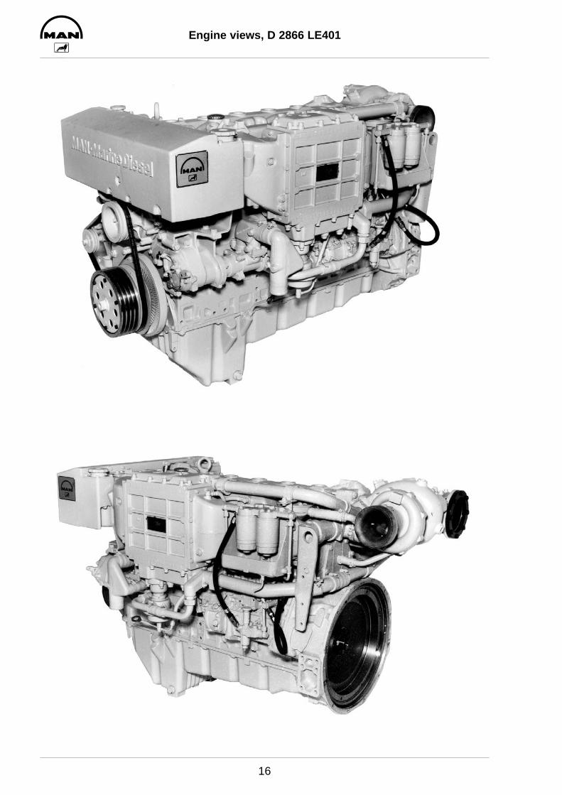
Engine views, D 2866 LE401
16

Engine views, D 2866 LE401
17

Cross section of engine
18
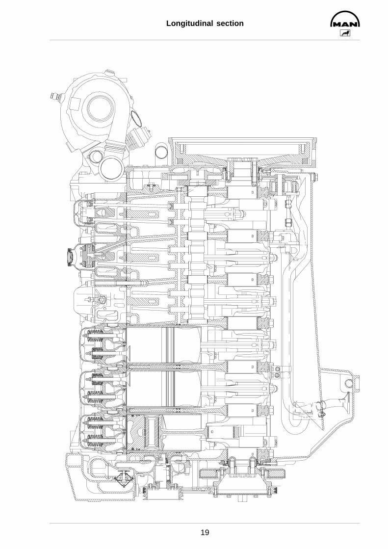
Longitudinal section
19
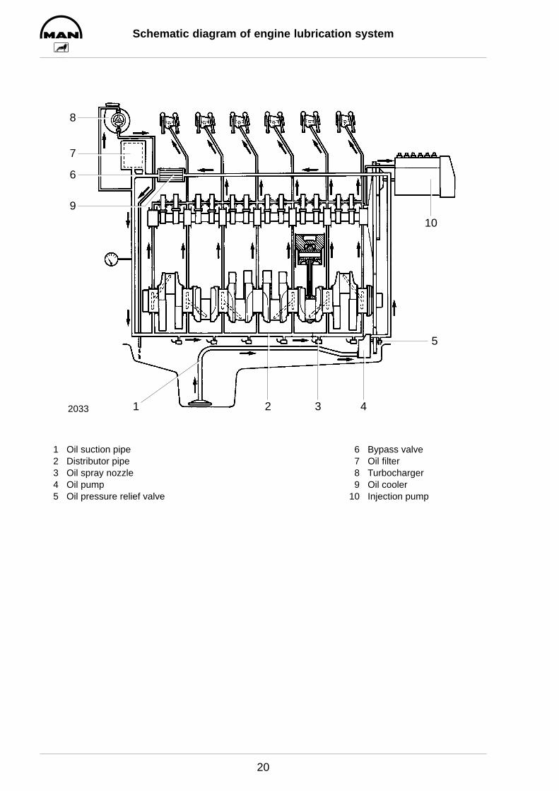
Schematic diagram of engine lubrication system
20
12033 2 3 4
5
9
6
7
8
10
1 Oil suction pipe 6 Bypass valve2 Distributor pipe 7 Oil filter3 Oil spray nozzle 8 Turbocharger4 Oil pump 9 Oil cooler5 Oil pressure relief valve 10 Injection pump
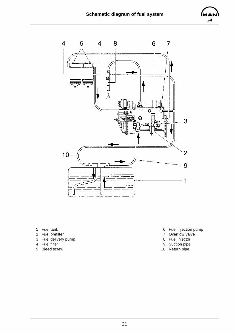
Schematic diagram of fuel system
21
1 Fuel tank 6 Fuel injection pump2 Fuel prefilter 7 Overflow valve3 Fuel delivery pump 8 Fuel injector4 Fuel filter 9 Suction pipe5 Bleed screw 10 Return pipe

Schematic diagram of cooling system
22
9
12345 76 8
10 111514 13
12
16
2583
1 Water pump housing with 9 Expansion tankintegrated thermostat housing 10 Over/underpressure valve
2 Water pump impeller 11 Coolant filler neck3 Engine oil cooler 12 Heating lead and return line4 Crankcase 13 Measuring point for cooling water temperature5 Exhaust manifold, liquid-cooled 14 Bleed screw on turbocharger6 Turbocharger, liquid-cooled 15 Raw water pump7 Thermostat 16 Intercooler8 Engine coolant/raw water heat exchanger
1
2
3
4
Checking and adjusting start of fuel delivery
23
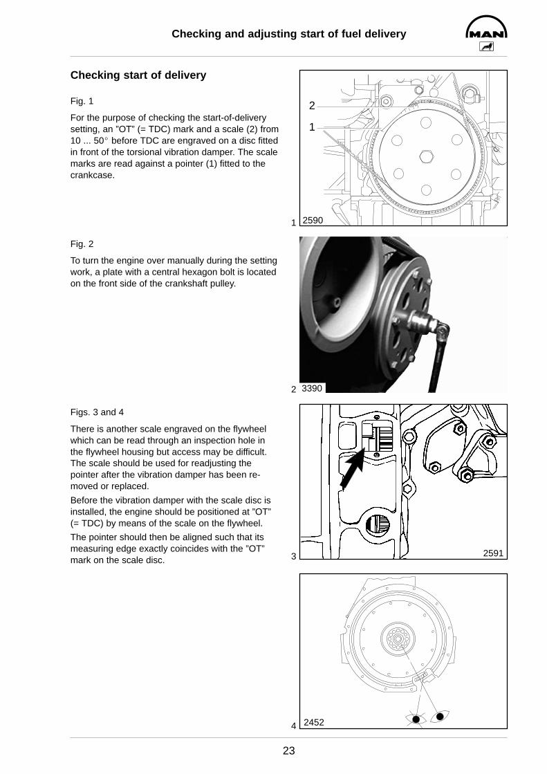
Checking start of delivery
Fig. 1
For the purpose of checking the start-of-deliverysetting, an ”OT” (= TDC) mark and a scale (2) from10 ... 50_ before TDC are engraved on a disc fittedin front of the torsional vibration damper. The scalemarks are read against a pointer (1) fitted to thecrankcase.
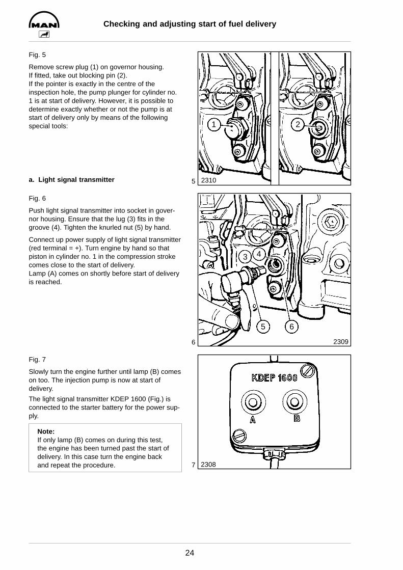
Fig. 2
To turn the engine over manually during the settingwork, a plate with a central hexagon bolt is locatedon the front side of the crankshaft pulley.
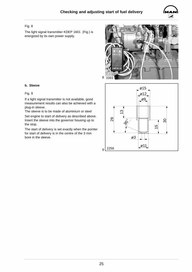
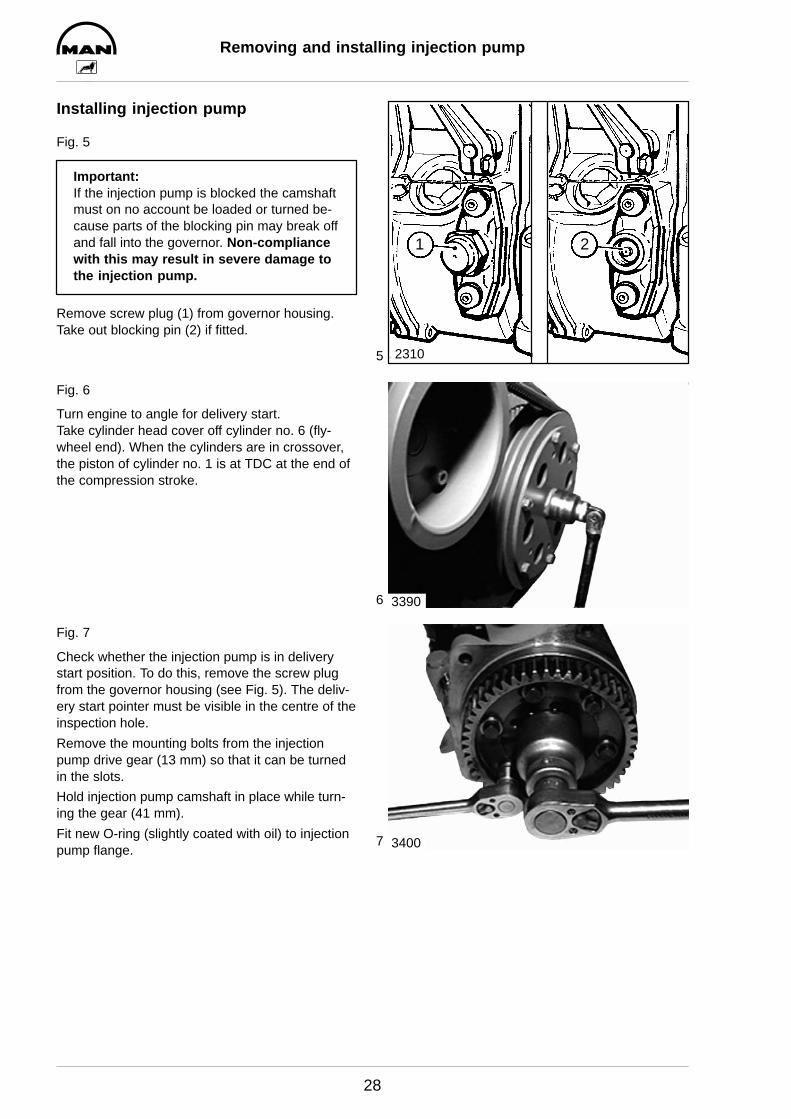
Figs. 3 and 4
There is another scale engraved on the flywheelwhich can be read through an inspection hole inthe flywheel housing but access may be difficult.The scale should be used for readjusting thepointer after the vibration damper has been re-moved or replaced.
Before the vibration damper with the scale disc isinstalled, the engine should be positioned at ”OT”(= TDC) by means of the scale on the flywheel.
The pointer should then be aligned such that itsmeasuring edge exactly coincides with the ”OT”mark on the scale disc.
2590
1
2
3390
2591
2452
5
6
7
Checking and adjusting start of fuel delivery
24
Fig. 5
Remove screw plug (1) on governor housing.If fitted, take out blocking pin (2).If the pointer is exactly in the centre of the inspection hole, the pump plunger for cylinder no.1 is at start of delivery. However, it is possible todetermine exactly whether or not the pump is atstart of delivery only by means of the followingspecial tools:
a. Light signal transmitter
Fig. 6
Push light signal transmitter into socket in gover-nor housing. Ensure that the lug (3) fits in thegroove (4). Tighten the knurled nut (5) by hand.
Connect up power supply of light signal transmitter(red terminal = +). Turn engine by hand so thatpiston in cylinder no. 1 in the compression strokecomes close to the start of delivery.Lamp (A) comes on shortly before start of deliveryis reached.
Fig. 7
Slowly turn the engine further until lamp (B) comeson too. The injection pump is now at start of delivery.
The light signal transmitter KDEP 1600 (Fig.) isconnected to the starter battery for the power sup-ply.
Note:If only lamp (B) comes on during this test,the engine has been turned past the start ofdelivery. In this case turn the engine backand repeat the procedure.
1 2
2310
3 4
5
2309
6
2308
8
9
Checking and adjusting start of fuel delivery
25
Fig. 8
The light signal transmitter KDEP 1601 (Fig.) isenergized by its own power supply.
b. Sleeve
Fig. 9
If a light signal transmitter is not available, goodmeasurement results can also be achieved with aplug-in sleeve.The sleeve is to be made of aluminium or steel
Set engine to start of delivery as described above.Insert the sleeve into the governor housing up tothe stop.
The start of delivery is set exactly when the pointerfor start of delivery is in the centre of the 3 mmbore in the sleeve.
3393
ø9
ø15
ø12
ø11
ø3
29
13
15
30
2259

10
11
12
Checking and adjusting start of fuel delivery
26
Adjusting start of delivery
If the check according to method a) or b) shouldprove that the delivery start is not correct, proceedas follows:
Fig. 10
Remove timing case cover (13mm).
Fig. 11
Loosen all bolts fastening the drive gear to the in-jection pump hub (13mm). For this, two completeturns of the engine are necessary.
Fig. 12
Turn engine to specified angle for delivery start.Remove cylinder head cover from cylinder no. 6(flywheel end). When the values of this cylinderare in crossover, the piston in cylinder no. 1 is atignition TDC.Remove screw plug from governor housing (seeFig. 5). The delivery start pointer must be visible inthe centre of the inspection hole.Turn the injection pump camshaft on the driveflange to the left or right until the conditions men-tioned under a) or b) apply.Tighten bolts for fastening drive gear to driveflange consecutively to 5 Nm and then to 30 Nm.Check delivery start once again.Close governor housing.
3394
2325
3395

1
2
3
4
Removing and installing injection pump
27
Removing injection pump
Fig. 1
Close cut–off valve from fuel tank to engine.
Remove all fuel and air (LDA) connections fromthe injection pump and detach the injection lines.
Caution:The lines contain fuel.Catch emerging fuel in a container.
Fig. 2
Remove bracket from the injection pump (19 mm).
Fig. 3
Remove the mounting bolts from the injectionpump flange (17 mm).
Note:For reasons of space the mounting bolt be-tween the injection pump and the crankcase(hexagon M10 bolt with reduced head 13mm) can be reached only with a 3/8” socketand an extension.
Fig. 4
Take off injection pump.
Note:Ensure meticulous cleanliness when workingon the injection pump.Prevent dirt and foreign matter from pene-trating into opened line connections.
3396
3397
3398
3399
5
6
7
Removing and installing injection pump
28
Installing injection pump
Fig. 5
Important:If the injection pump is blocked the camshaftmust on no account be loaded or turned be-cause parts of the blocking pin may break offand fall into the governor. Non-compliancewith this may result in severe damage tothe injection pump.
Remove screw plug (1) from governor housing.Take out blocking pin (2) if fitted.
Fig. 6
Turn engine to angle for delivery start.Take cylinder head cover off cylinder no. 6 (fly-wheel end). When the cylinders are in crossover,the piston of cylinder no. 1 is at TDC at the end ofthe compression stroke.
Fig. 7
Check whether the injection pump is in deliverystart position. To do this, remove the screw plugfrom the governor housing (see Fig. 5). The deliv-ery start pointer must be visible in the centre of theinspection hole.
Remove the mounting bolts from the injectionpump drive gear (13 mm) so that it can be turnedin the slots.
Hold injection pump camshaft in place while turn-ing the gear (41 mm).
Fit new O-ring (slightly coated with oil) to injectionpump flange.
1 2
2310
3390
3400
8
9
Removing and installing injection pump
29
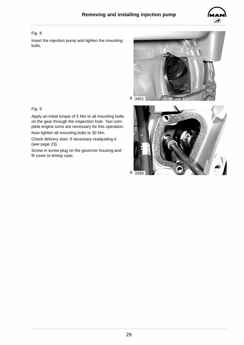
Fig. 8
Insert the injection pump and tighten the mountingbolts.
Fig. 9
Apply an initial torque of 5 Nm to all mounting boltson the gear through the inspection hole. Two com-plete engine turns are necessary for this operation.
Now tighten all mounting bolts to 30 Nm.
Check delivery start, if necessary readjusting it(see page 23).
Screw in screw plug on the governor housing andfit cover to timing case.
3401
3395

1
2
3
4
Removing and installing fuel injectors
30
Removing fuel injectors
Fig. 1
Remove leakage fuel return lines.
Fig. 2
Remove injection lines.
Fig. 3
Remove pressure screw from fuel injector using apin spanner.
Fig. 4
Bolt inertia puller on to fuel injector and knock outthe injector.
3402
3403
3378
3404
5
6
7
Removing and installing fuel injectors
31
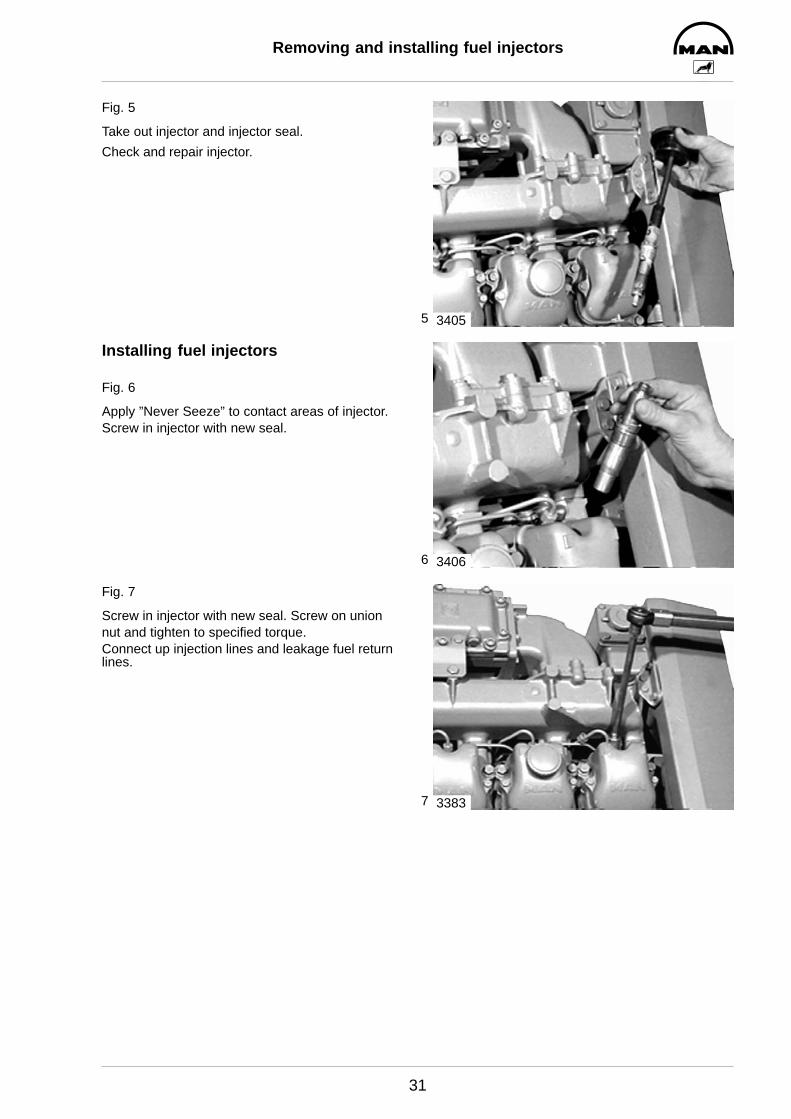
Fig. 5
Take out injector and injector seal.
Check and repair injector.
Installing fuel injectors
Fig. 6
Apply ”Never Seeze” to contact areas of injector.Screw in injector with new seal.
Fig. 7
Screw in injector with new seal. Screw on unionnut and tighten to specified torque.Connect up injection lines and leakage fuel returnlines.
3405
3406
3383

1
2
Checking and repairing fuel injectors
32
Checking fuel injectors
Fig. 1
The nozzle tester (manual test stand) is used to check the– opening pressure– tightness– spray pattern of the injection nozzle.
Use pure testing oil or pure Diesel fuel for the test.Prior to testing, clean nozzle and check it for wear.
Fig. 2
Check injector assembly.Connect the nozzle’s supply connection to the testunit’s pressure line.
Caution:The high opening pressure may leadto severe injuries. Do not place handsunder the jet. Wear safety goggles.
1. Checking opening pressure:Switch on the pressure gauge and slowly presslever downwards until the nozzle emits a jet with alight grating noise.Read opening pressure from the pressure gauge.In the event of a pressure deviation insert a differ-ent shim. If the pressure is too low, insert thickershims, if it is too high, insert thinner shims (7). Theinitial tension of the compression spring (6) de-creases if a high number of operating hours hasbeen clocked up. Consequently, the injection pres-sure drops slightly. When repairing injectionnozzles, always set the opening pressure to theupper limit (+ 8 bar).
Note:Shims are available in 0.02 mm steps from1.0 mm to 1.98 mm.
2. Checking tightness:Actuate hand lever. At a pressure of 20 bar belowthe opening pressure set not a single drop mustfall from the nozzle opening within 10 sec.
3. Checking jet:Switch off pressure gauge and carry out someswift strokes. The nozzle must emit an audiblegrating noise and/or a well-atomised jet.
Nozzles that satisfy these three requirements canbe reused.
2581
2
3
4
5
6
78
26441
1 Seal2 Nozzle tension nut3 Injection nozzle4 Intermediate washer5 Pressure pin6 Compression spring7 Shim8 Circlip
3
4
5
6
Checking and repairing fuel injectors
33
Disassembling fuel injectors
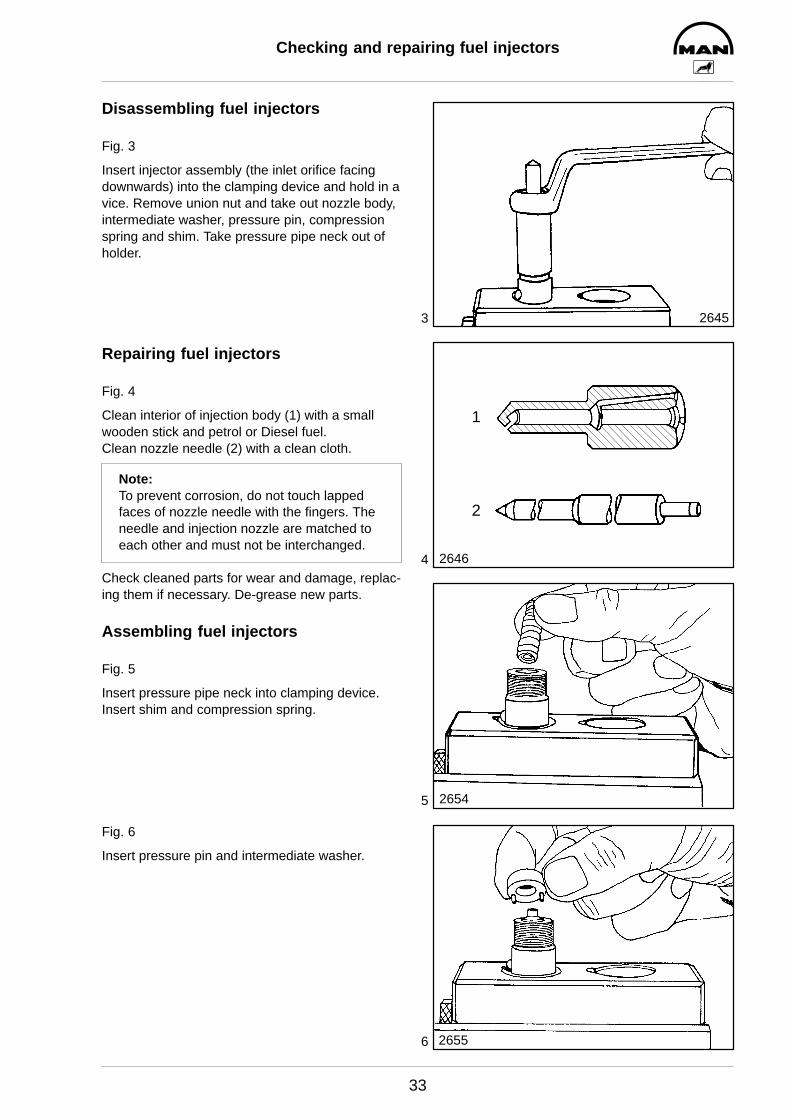
Fig. 3
Insert injector assembly (the inlet orifice facingdownwards) into the clamping device and hold in avice. Remove union nut and take out nozzle body,intermediate washer, pressure pin, compressionspring and shim. Take pressure pipe neck out ofholder.
Repairing fuel injectors
Fig. 4
Clean interior of injection body (1) with a smallwooden stick and petrol or Diesel fuel.Clean nozzle needle (2) with a clean cloth.
Note:To prevent corrosion, do not touch lappedfaces of nozzle needle with the fingers. Theneedle and injection nozzle are matched toeach other and must not be interchanged.
Check cleaned parts for wear and damage, replac-ing them if necessary. De-grease new parts.
Assembling fuel injectors
Fig. 5
Insert pressure pipe neck into clamping device.Insert shim and compression spring.
Fig. 6
Insert pressure pin and intermediate washer.
2645
2646
1
2
2654
2655
7
8
9
Checking and repairing fuel injectors
34
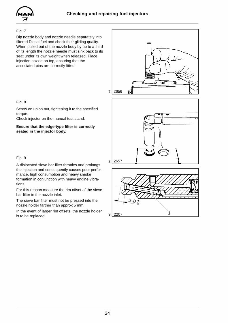
Fig. 7
Dip nozzle body and nozzle needle separately intofiltered Diesel fuel and check their gliding quality.When pulled out of the nozzle body by up to a thirdof its length the nozzle needle must sink back to itsseat under its own weight when released. Placeinjection nozzle on top, ensuring that theassociated pins are correctly fitted.
Fig. 8
Screw on union nut, tightening it to the specifiedtorque.Check injector on the manual test stand.
Ensure that the edge-type filter is correctly seated in the injector body.
Fig. 9
A dislocated sieve bar filter throttles and prolongsthe injection and consequently causes poor perfor-mance, high consumption and heavy smokeformation in conjunction with heavy engine vibra-tions.
For this reason measure the rim offset of the sievebar filter in the nozzle inlet.
The sieve bar filter must not be pressed into thenozzle holder farther than approx 5 mm.
In the event of larger rim offsets, the nozzle holderis to be replaced.
2656
2657
12207

1
2
3
Cleaning fuel prefilter
35
Fig. 1
Shut cut-off valve from fuel tank to engine.
Remove round nut and take off filter housing withsieve.
Use a bowl to catch fuel that may emerge.
Fig. 2
Wash out filter housing and gauze filter in cleanDiesel fuel and blow them out with compressed air.
Reassemble fuel prefilter using new seal.
Fig. 3
Actuate plunger of hand priming pump until theoverflow valve of the injection pump opens audibly.
Check fuel pre-filter for leaks while engine is run-ning.
3407
3408
3409
1
2
3
4
Changing fuel filter cartridges
36
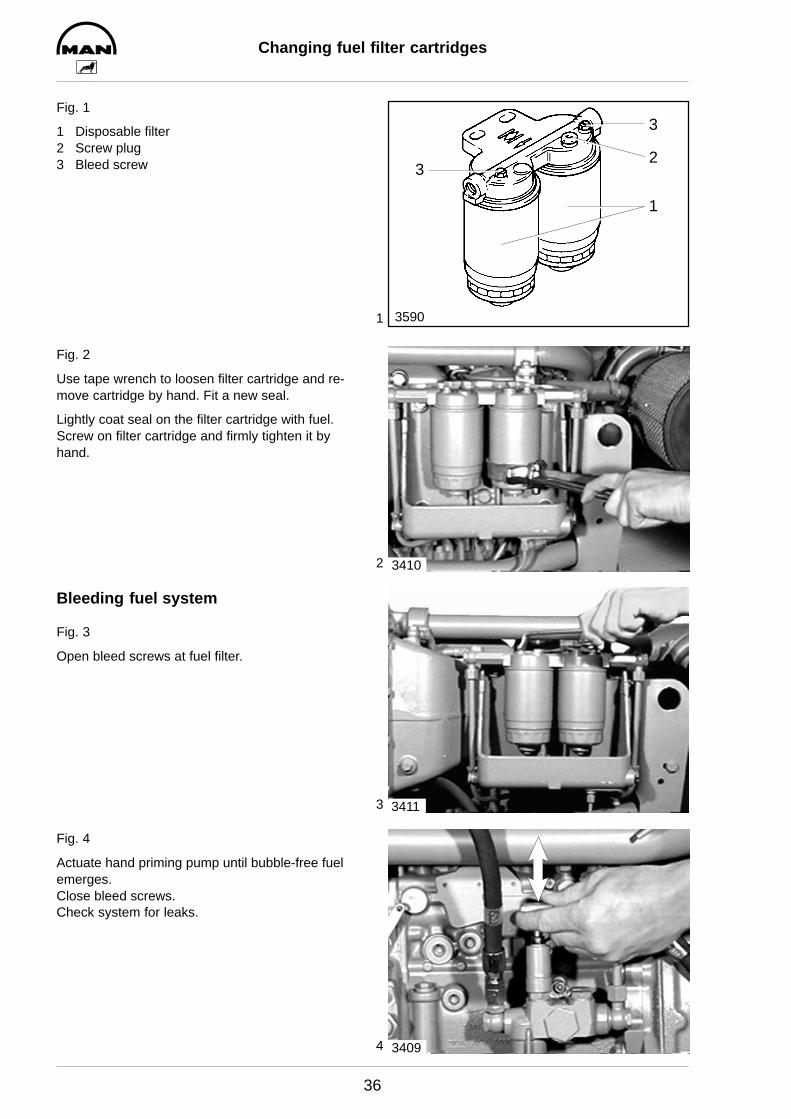
Fig. 1
1 Disposable filter2 Screw plug3 Bleed screw
Fig. 2
Use tape wrench to loosen filter cartridge and re-move cartridge by hand. Fit a new seal.
Lightly coat seal on the filter cartridge with fuel.Screw on filter cartridge and firmly tighten it byhand.
Bleeding fuel system
Fig. 3
Open bleed screws at fuel filter.
Fig. 4
Actuate hand priming pump until bubble-free fuelemerges.Close bleed screws.Check system for leaks.
3
3
2
1
3590
3410
3411
3409

1
2
3
Draining and filling with coolant
37
Draining coolant
Drain coolant as follows when the engine is cold:
Caution:Risk of scalding if hot coolant isdrained! Drain coolant into a containerand dispose of it in accordance withlocal regulations
Fig. 1
Remove cap (arrow) from filler neck on the coolantexpansion tank. Open drain plugs.
Fig. 2
Open drain plug in the oil cooler housing.
Use a container to catch coolant that may emerge.
Fig. 3
Further drain plugs for draining the coolant are lo-cated on the exhaust-gas collector pipe (picture)and on the intercooler.
3412
3413
3414
4
5
6
Draining and filling with coolant
38
Filling up with coolant
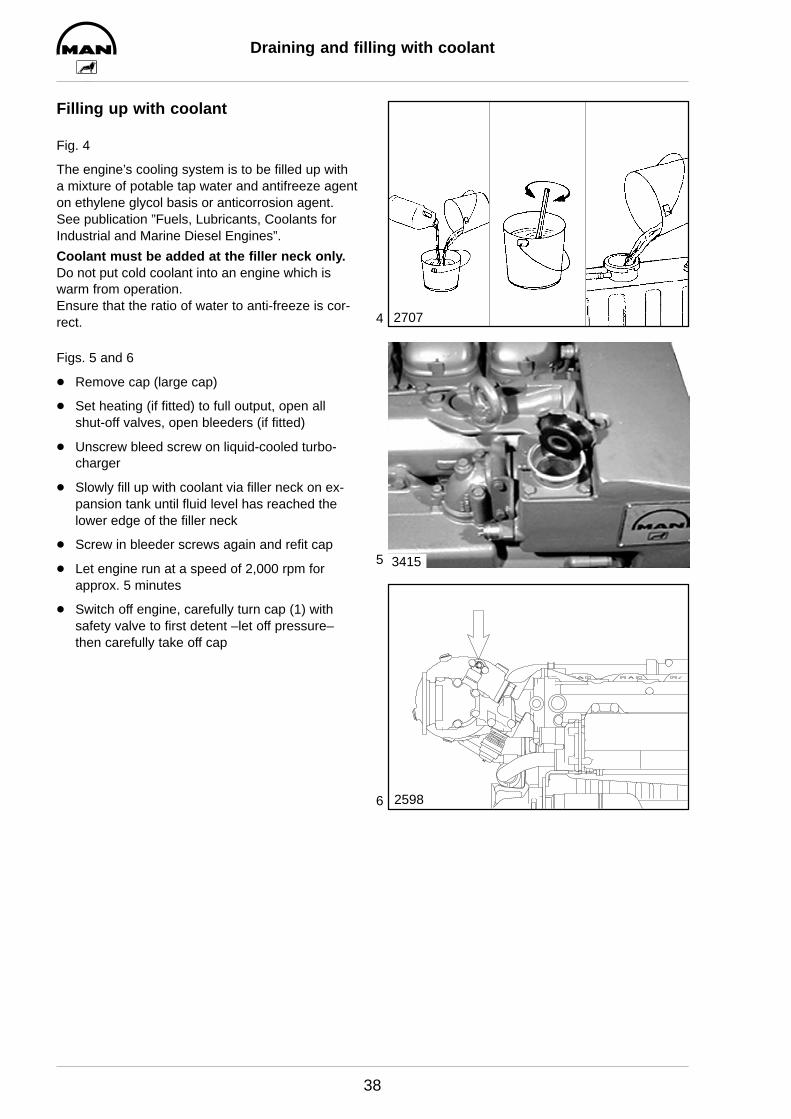
Fig. 4
The engine’s cooling system is to be filled up witha mixture of potable tap water and antifreeze agenton ethylene glycol basis or anticorrosion agent.See publication ”Fuels, Lubricants, Coolants forIndustrial and Marine Diesel Engines”.
Coolant must be added at the filler neck only.Do not put cold coolant into an engine which iswarm from operation. Ensure that the ratio of water to anti-freeze is cor-rect.
Figs. 5 and 6
D Remove cap (large cap)
D Set heating (if fitted) to full output, open allshut-off valves, open bleeders (if fitted)
D Unscrew bleed screw on liquid-cooled turbo-charger
D Slowly fill up with coolant via filler neck on ex-pansion tank until fluid level has reached thelower edge of the filler neck
D Screw in bleeder screws again and refit cap
D Let engine run at a speed of 2,000 rpm forapprox. 5 minutes
D Switch off engine, carefully turn cap (1) withsafety valve to first detent –let off pressure–then carefully take off cap
2707
3415
2598

1
2
3
Removing and installing thermostat
39
Fig. 1
D Drain coolant, see page 37D Remove expansion tank, see page 45
Once the expansion tank has been removed thethermostats in the water pump housing are visible.
Fig. 2
Take out thermostat.
Check the function of the thermostat as follows.
D Hang thermostat in a pot filled with waterD Heat waterD Use suitable thermometer to ascertain the
opening start and compare it with the set–pointvalue given in ”Engineering S Data S Setting val-ues”.
D Measure opening stroke if necessary.
Exchange defective thermostats.
Fig. 3
Insert thermostat inserts (ball valve facing upwards(”TOP”) with new O-ring seal (1) and new seal (2).
3428
3429
1
2
1
2
3
Removing and installing water pump
40
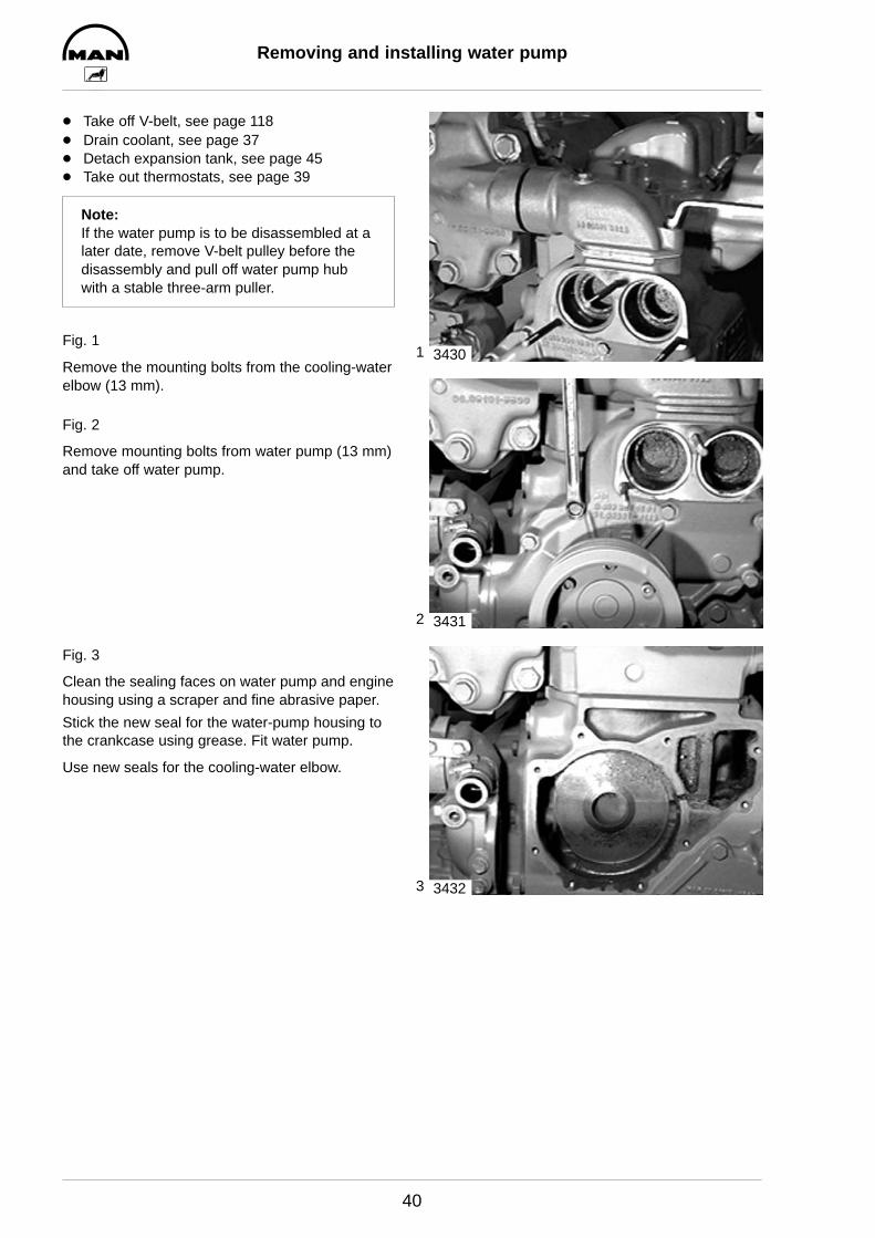
D Take off V-belt, see page 118D Drain coolant, see page 37D Detach expansion tank, see page 45D Take out thermostats, see page 39
Note:If the water pump is to be disassembled at alater date, remove V-belt pulley before thedisassembly and pull off water pump hubwith a stable three-arm puller.
Fig. 1
Remove the mounting bolts from the cooling-waterelbow (13 mm).
Fig. 2
Remove mounting bolts from water pump (13 mm)and take off water pump.
Fig. 3
Clean the sealing faces on water pump and enginehousing using a scraper and fine abrasive paper.
Stick the new seal for the water-pump housing tothe crankcase using grease. Fit water pump.
Use new seals for the cooling-water elbow.
3430
3431
3432
1
2
3
4
Repairing water pump
41
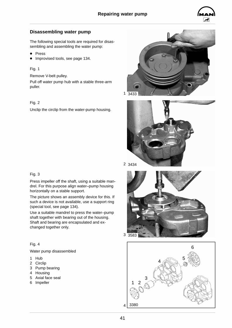
Disassembling water pump
The following special tools are required for disas-sembling and assembling the water pump:
D PressD Improvised tools, see page 134.
Fig. 1
Remove V-belt pulley.
Pull off water pump hub with a stable three-armpuller.
Fig. 2
Unclip the circlip from the water-pump housing.
Fig. 3
Press impeller off the shaft, using a suitable man-drel. For this purpose align water–pump housinghorizontally on a stable support.
The picture shows an assembly device for this. Ifsuch a device is not available, use a support ring(special tool, see page 134).
Use a suitable mandrel to press the water–pumpshaft together with bearing out of the housing.Shaft and bearing are encapsulated and ex-changed together only.
Fig. 4
Water pump disassembled
1 Hub2 Circlip3 Pump bearing4 Housing5 Axial face seal6 Impeller
3433
3434
3583
3380
4
1 23
5
6
5
6
7
Repairing water pump
42
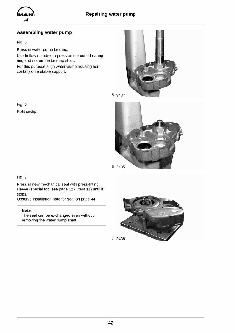
Assembling water pump
Fig. 5
Press in water pump bearing.
Use hollow mandrel to press on the outer bearingring and not on the bearing shaft.
For this purpose align water-pump housing hori-zontally on a stable support.
Fig. 6
Refit circlip.
Fig. 7
Press in new mechanical seal with press-fittingsleeve (special tool see page 127, item 11) until itstops.Observe installation note for seal on page 44.
Note:The seal can be exchanged even withoutremoving the water pump shaft.
3437
3435
3438
8
9
Repairing water pump
43
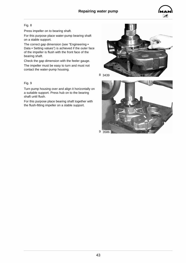
Fig. 8
Press impeller on to bearing shaft.
For this purpose place water-pump bearing shafton a stable support.
The correct gap dimension (see ”Engineering SData S Setting values”) is achieved if the outer faceof the impeller is flush with the front face of thebearing shaft.
Check the gap dimension with the feeler gauge.
The impeller must be easy to turn and must notcontact the water-pump housing.
Fig. 9
Turn pump housing over and align it horizontally ona suitable support. Press hub on to the bearingshaft until flush.
For this purpose place bearing shaft together withthe flush-fitting impeller on a stable support.
3439
3586
Repairing water pump
44
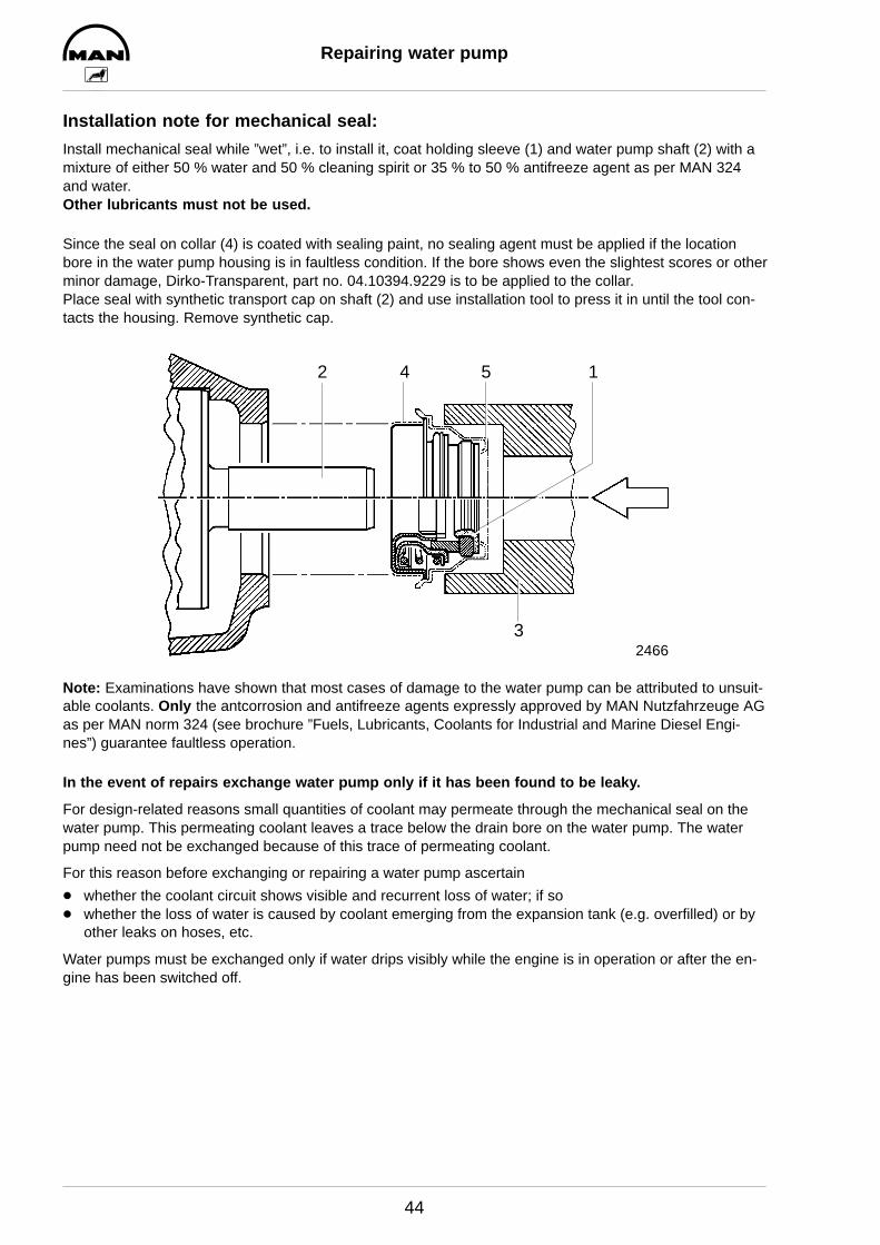
Installation note for mechanical seal:
Install mechanical seal while ”wet”, i.e. to install it, coat holding sleeve (1) and water pump shaft (2) with amixture of either 50 % water and 50 % cleaning spirit or 35 % to 50 % antifreeze agent as per MAN 324 and water.Other lubricants must not be used.
Since the seal on collar (4) is coated with sealing paint, no sealing agent must be applied if the locationbore in the water pump housing is in faultless condition. If the bore shows even the slightest scores or otherminor damage, Dirko-Transparent, part no. 04.10394.9229 is to be applied to the collar.Place seal with synthetic transport cap on shaft (2) and use installation tool to press it in until the tool con-tacts the housing. Remove synthetic cap.
3
1542
2466
Note: Examinations have shown that most cases of damage to the water pump can be attributed to unsuit-able coolants. Only the antcorrosion and antifreeze agents expressly approved by MAN Nutzfahrzeuge AGas per MAN norm 324 (see brochure ”Fuels, Lubricants, Coolants for Industrial and Marine Diesel Engi-nes”) guarantee faultless operation.
In the event of repairs exchange water pump only if it has been found to be leaky.
For design-related reasons small quantities of coolant may permeate through the mechanical seal on thewater pump. This permeating coolant leaves a trace below the drain bore on the water pump. The waterpump need not be exchanged because of this trace of permeating coolant.
For this reason before exchanging or repairing a water pump ascertain
D whether the coolant circuit shows visible and recurrent loss of water; if soD whether the loss of water is caused by coolant emerging from the expansion tank (e.g. overfilled) or by
other leaks on hoses, etc.
Water pumps must be exchanged only if water drips visibly while the engine is in operation or after the en-gine has been switched off.
1
2
3
4
Removing and attaching expansion tank
45
D Drain coolant, see page 37
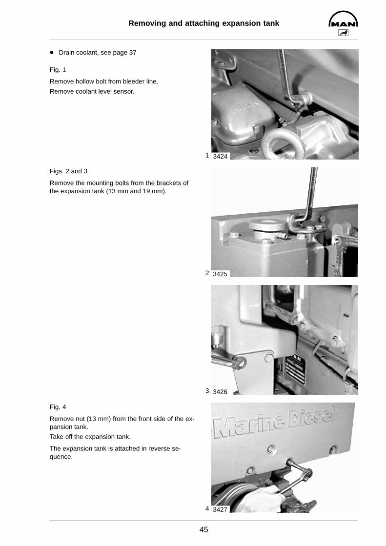
Fig. 1
Remove hollow bolt from bleeder line.
Remove coolant level sensor.
Figs. 2 and 3
Remove the mounting bolts from the brackets ofthe expansion tank (13 mm and 19 mm).
Fig. 4
Remove nut (13 mm) from the front side of the ex-pansion tank.
Take off the expansion tank.
The expansion tank is attached in reverse se-quence.
3424
3425
3426
3427
1
2
3
Removing and installing heat exchanger
46
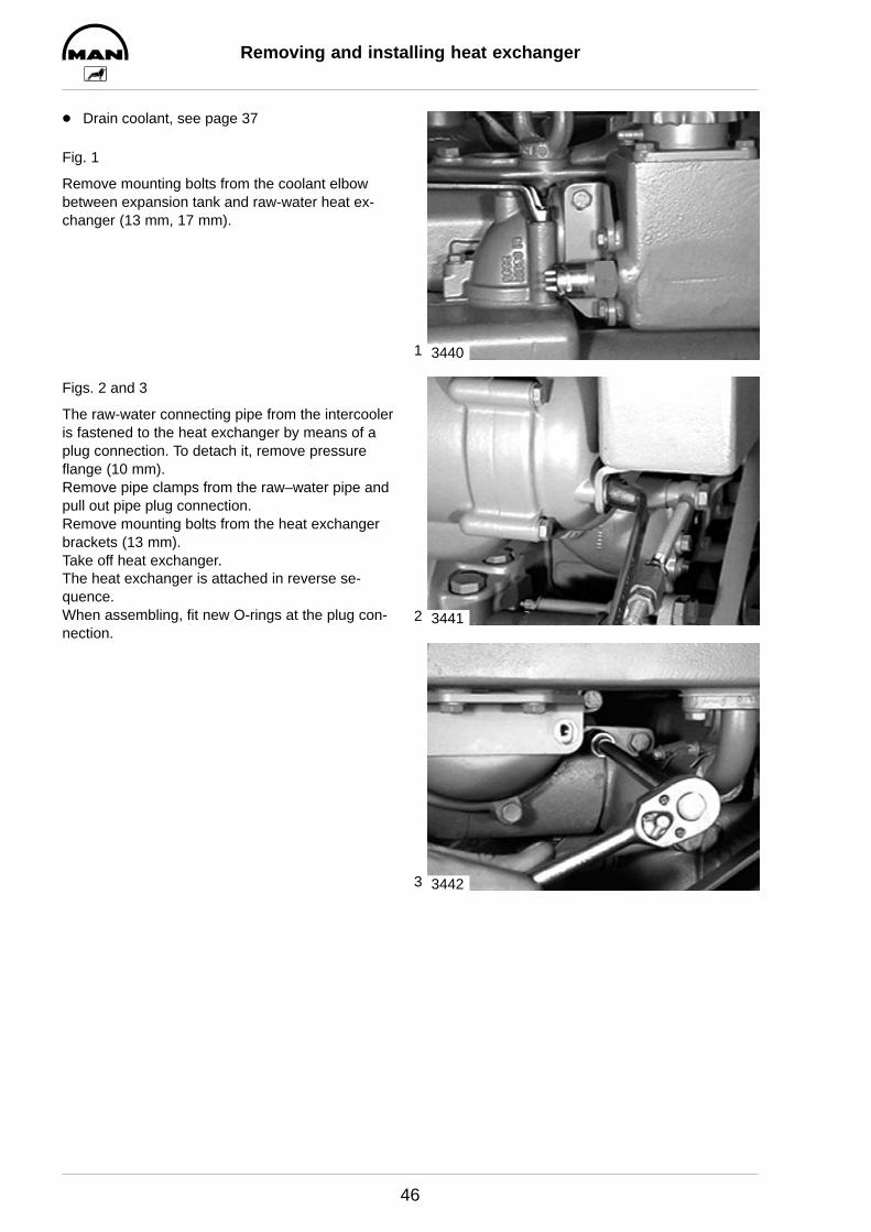
D Drain coolant, see page 37
Fig. 1
Remove mounting bolts from the coolant elbowbetween expansion tank and raw-water heat ex-changer (13 mm, 17 mm).
Figs. 2 and 3
The raw-water connecting pipe from the intercooleris fastened to the heat exchanger by means of aplug connection. To detach it, remove pressureflange (10 mm).Remove pipe clamps from the raw–water pipe andpull out pipe plug connection.Remove mounting bolts from the heat exchangerbrackets (13 mm).Take off heat exchanger.The heat exchanger is attached in reverse se-quence.When assembling, fit new O-rings at the plug con-nection.
3440
3441
3442

1
2
3
4
Removing and installing heat-exchanger pipe set
47
D Remove raw-water heat exchanger,see page 46
Fig. 1
Match-mark the position of the covers relative tothe heat-exchanger housing (arrow) and removeboth covers (13 mm).
Fig. 2
Take off cover.At the flywheel end of the heat exchanger the col-lar of the pipe cluster (arrow) is visible.
Fig. 3
Carefully knock out pipe cluster from the oppositeend using a block of wood.
Fig. 4
Pull out pipe cluster.The pipe cluster is installed in reverse sequence.When installing the pipe cluster, use new O-ringsand check the heat exchanger for leaks.
3443
3444
3445
3446
Cleaning heat exchanger pipe set
48
Internal cleaning of the pipe set in raw water heat exchangers
Deposits may form on the sea–water side of the pipe cluster in the heat exchanger, impairing the heat tran-sition to such an extent that the coolant heat can no longer be sufficiently conducted away. This is bound tocause an increase in the coolant temperature.
In the event of an increase in coolant temperature, check all other components of the cooling system first.
D Raw-water filter contaminated?
D Raw-water inlet clogged up?
D Flow rate of raw water sufficient? Impeller of raw-water pump worn?
If all components of the cooling system are in order, but the coolant temperature remains neverthelesshigh, cleaning the pipe cluster may eliminate the fault.
Proceed as follows:
D Lay or stand removed pipe set in a suitable container made of synthetic material such as PE, PP, PVC,GRP etc.
D Fill container with undiluted genuine pickling liquid at room temperature (engine pickling fluid RB-06)until the pipe set is completely submerged.
D Allow pickling fluid to soak in for approx. 10 hours. If this period of time is not sufficient, allow another 5 hours
D The pickling period can be shortened by heating up the pickling fluid up to a maximum of 50_C (120_F)and by moving the set of pipes from time to time.
D After the pickling the pipe set is to be intensively rinsed with tap water and again installed in the heat exchanger.
D Use new seals (O-ring seals) for the caps.
D Install pipe set and check heat exchanger for leaks.
Waste water conditioning
With the aid of soda lye the drained and used cleaning and pickling fluid is conditioned to a pH value of 7.5to 8.5. After the sediments have settled the clear fluid above can be drained into the sewerage system. Thesludge is to be taken to a dump for special waste.
1
2
3
Raw water pump
49
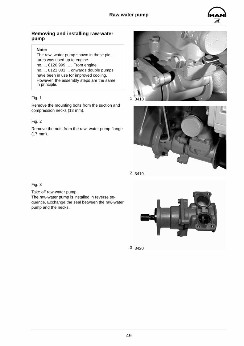
Removing and installing raw-waterpump
Note:The raw–water pump shown in these pic-tures was used up to engine no. ... 8120 999 ... . From engine no. ... 8121 001 ... onwards double pumpshave been in use for improved cooling.However, the assembly steps are the samein principle.
Fig. 1
Remove the mounting bolts from the suction andcompression necks (13 mm).
Fig. 2
Remove the nuts from the raw–water pump flange(17 mm).
Fig. 3
Take off raw-water pump.The raw-water pump is installed in reverse se-quence. Exchange the seal between the raw-waterpump and the necks.
3418
3419
3420

1
2
3
Raw water pump
50
Changing impeller
Fig. 1
Remove cover (8 mm).
Fig. 2
The impeller can be removed only together withthe cam.
Note:The impeller will be destroyed if it is forciblypulled out without the cam.
To do this, remove the cap screw in the pumphousing between the suction and the compressionneck using a screwdriver.
Fig. 3
Pull out impeller together with the cam using a pairof pliers.
Exchange worn or damaged impeller together withthe wearing parts (repair kit) (observe the directionof rotation).
Coat new impeller slightly with Vaseline before as-sembling it.
When assembling, secure cap screw with Loctite 648.
Fit cover with new seal.
Operating the impeller while it is dry entails irrepa-rable damage. Fill pump with water before com-missioning it and check it for leaks.
3421
3422
3423
1
2
3
Changing oil filter
51
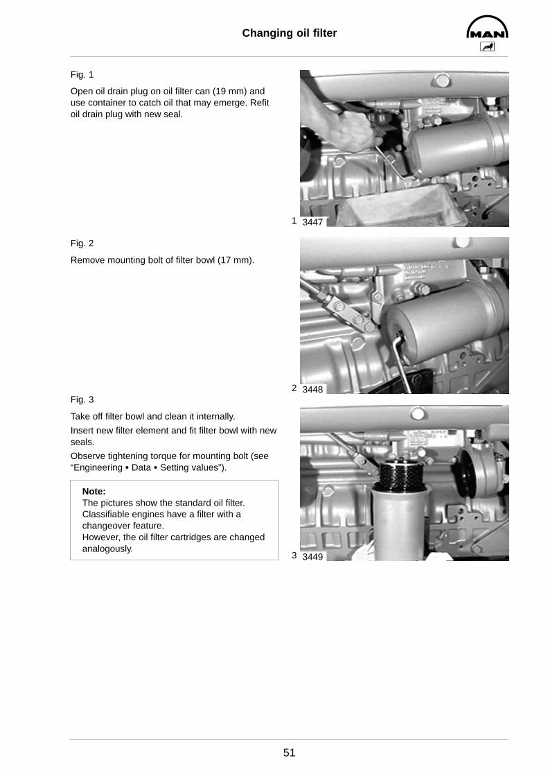
Fig. 1
Open oil drain plug on oil filter can (19 mm) anduse container to catch oil that may emerge. Refitoil drain plug with new seal.
Fig. 2
Remove mounting bolt of filter bowl (17 mm).
Fig. 3
Take off filter bowl and clean it internally.
Insert new filter element and fit filter bowl with newseals.
Observe tightening torque for mounting bolt (see“Engineering S Data S Setting values”).
Note:The pictures show the standard oil filter.Classifiable engines have a filter with achangeover feature.However, the oil filter cartridges are changedanalogously.
3447
3448
3449
1
2
3
Removing and installing oil cooler
52
D Drain engine oilD Drain coolant, see page 37.D Remove oil filter, see page 51.
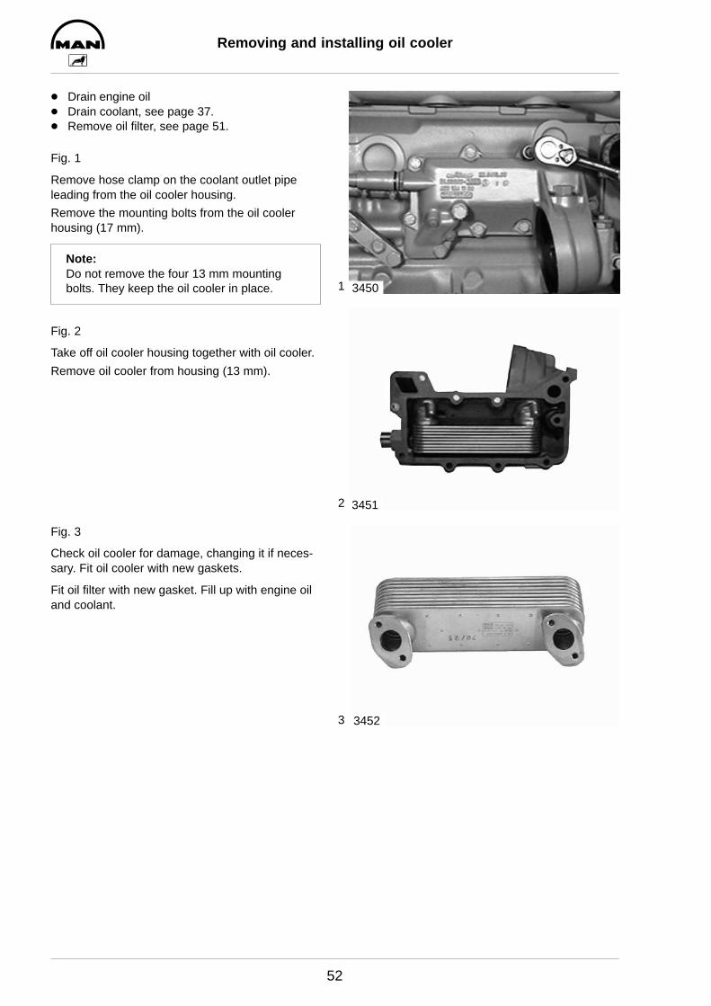
Fig. 1
Remove hose clamp on the coolant outlet pipeleading from the oil cooler housing.
Remove the mounting bolts from the oil coolerhousing (17 mm).
Note:Do not remove the four 13 mm mountingbolts. They keep the oil cooler in place.
Fig. 2
Take off oil cooler housing together with oil cooler.
Remove oil cooler from housing (13 mm).
Fig. 3
Check oil cooler for damage, changing it if neces-sary. Fit oil cooler with new gaskets.
Fit oil filter with new gasket. Fill up with engine oiland coolant.
3450
3451
3452
1
2
3
4
Removing and installing oil pump
53
Removing oil pump
D Drain engine oil.
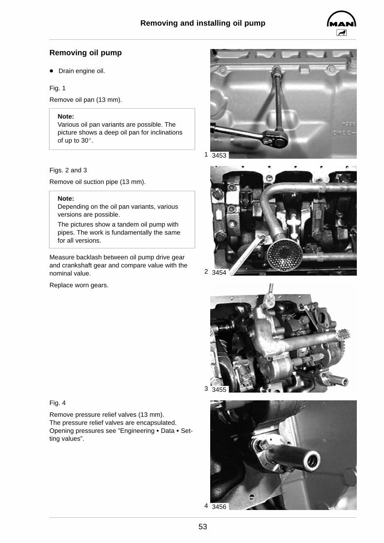
Fig. 1
Remove oil pan (13 mm).
Note:Various oil pan variants are possible. Thepicture shows a deep oil pan for inclinationsof up to 30_.
Figs. 2 and 3
Remove oil suction pipe (13 mm).
Note:Depending on the oil pan variants, variousversions are possible.
The pictures show a tandem oil pump withpipes. The work is fundamentally the samefor all versions.
Measure backlash between oil pump drive gearand crankshaft gear and compare value with thenominal value.
Replace worn gears.
Fig. 4
Remove pressure relief valves (13 mm).The pressure relief valves are encapsulated.Opening pressures see ”Engineering S Data S Set-ting values”.
3453
3454
3455
3456

5
6
7
Removing and installing oil pump
54
Fig. 5
Remove oil pump.
Note:Depending on the engine model and oil panvariant, various oil pump versions are possible.
In engines with tandem pumps, first remove the2nd pump À with intermediate shaft Á, connectionsleeves  and circlips Ã.
Disassembling and assembling oilpump
Fig. 6
Clamp oil pump in a vice (fitted with soft jaws). Re-move oil pump cover (13 mm).
Fig. 7
Pull driven oil pump gears out of the housing.Check gears and pump housing for wear (see ”Engineering S Data S Setting values”).
1
2
3
3
4
4
2703
3669
3458

8
9
Removing and installing oil pump
55
Fig. 8
Remove oil pump drive gear. To do this, lay pumpon suitable support and press off drive gear usinga mandrel.Place drive gear on the shaft and press it intoplace. Thereby support opposite shaft end. Pres-sing force see ”Engineering S Data S Setting va-lues”.
Checking axial play of the pump gears
Fig. 9
Position dial gauge and push shaft up to the stopin one direction and set dial gauge to - 0 -. Pushshaft in opposite direction and read the movementfrom the dial gauge.
3459
3582
10
11
12
Removing and installing oil pump
56
Installing oil pump
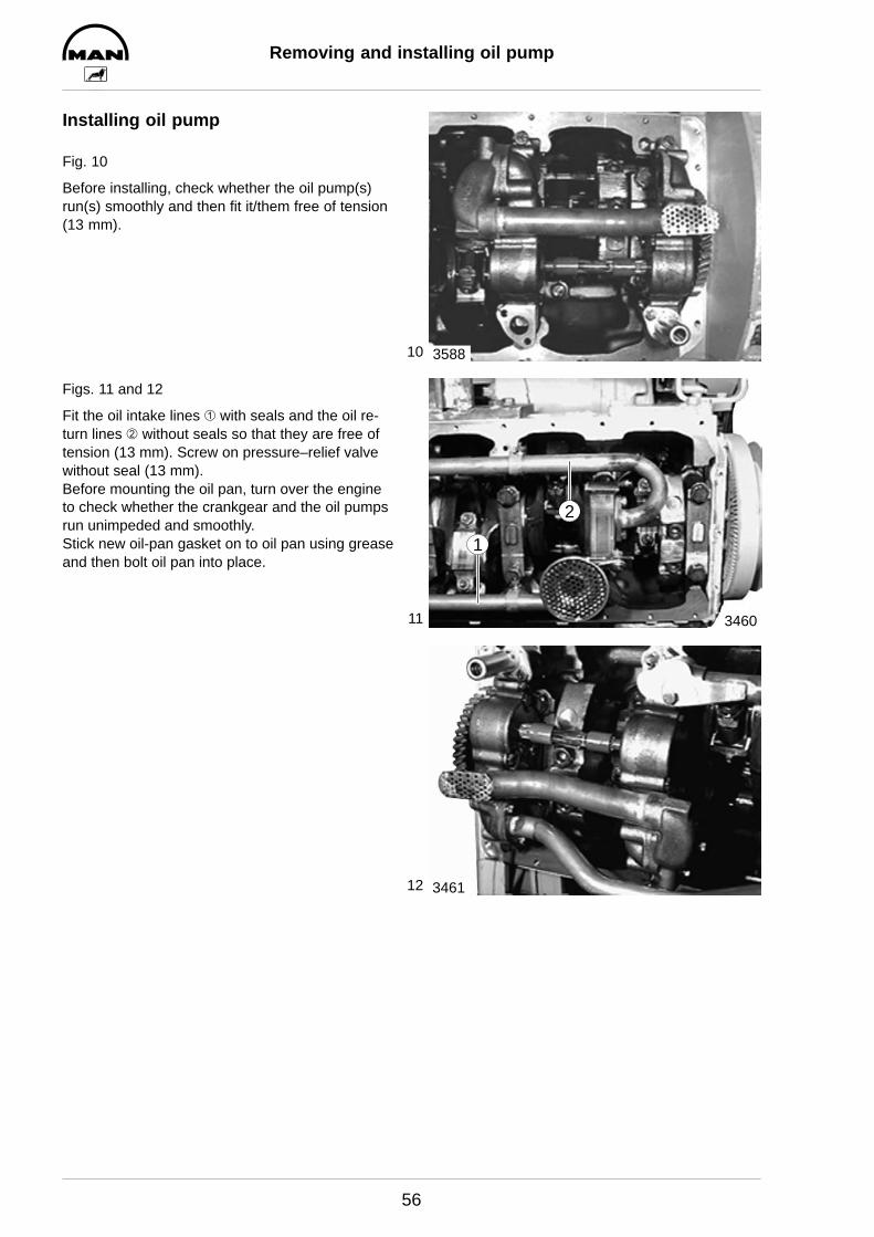
Fig. 10
Before installing, check whether the oil pump(s)run(s) smoothly and then fit it/them free of tension(13 mm).
Figs. 11 and 12
Fit the oil intake lines À with seals and the oil re-turn lines Á without seals so that they are free oftension (13 mm). Screw on pressure–relief valvewithout seal (13 mm).Before mounting the oil pan, turn over the engineto check whether the crankgear and the oil pumpsrun unimpeded and smoothly.Stick new oil-pan gasket on to oil pan using greaseand then bolt oil pan into place.
3588
3460
1
2
3461
1
2
3
4
Oil spray nozzle
57
Removing oil spray nozzle
D Drain engine oilD Remove oil pan, see page 53
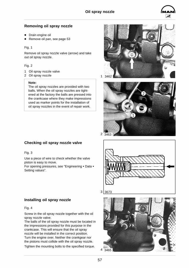
Fig. 1
Remove oil spray nozzle valve (arrow) and takeout oil spray nozzle.
Fig. 2
1 Oil spray nozzle valve2 Oil spray nozzle
Note:The oil spray nozzles are provided with twoballs. When the oil spray nozzles are tight-ened at the factory the balls are pressed intothe crankcase where they make impressionsused as marker points for the installation ofoil spray nozzles in the event of repair work.
Checking oil spray nozzle valve
Fig. 3
Use a piece of wire to check whether the valvepiston is easy to move.For opening pressures, see ”Engineering S Data SSetting values”.
Installing oil spray nozzle
Fig. 4
Screw in the oil spray nozzle together with the oilspray nozzle valve.The balls of the oil spray nozzle must be located inthe impressions provided for this purpose in thecrankcase. This will ensure that the oil spraynozzle will be installed in the correct position.Turn the engine over. Neither the crankgear northe pistons must collide with the oil spray nozzle.
Tighten the mounting bolts to the specified torque.
3462
3463
2
1
3673
3465
1
2
3
4
Removing and installing vibration damper,changing front crankshaft seal
58
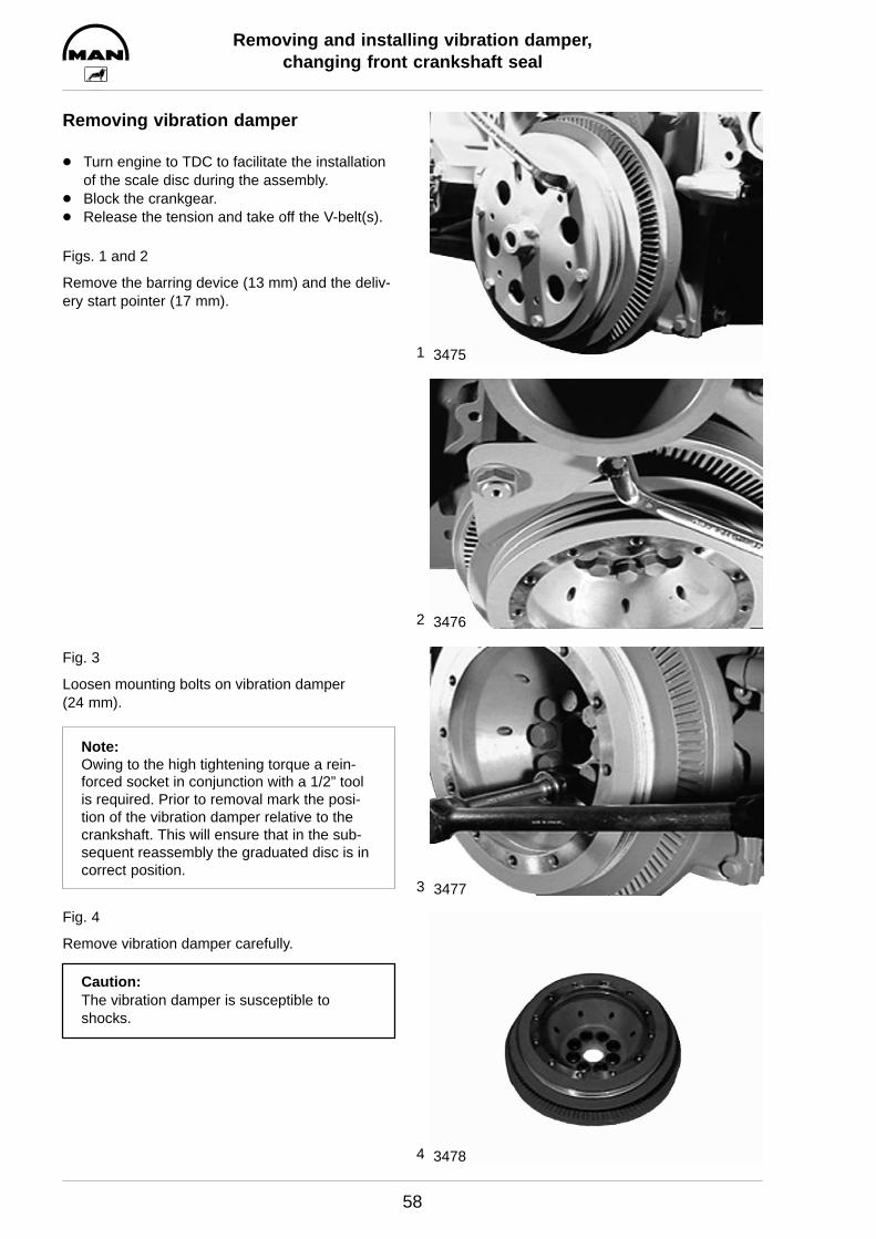
Removing vibration damper
D Turn engine to TDC to facilitate the installationof the scale disc during the assembly.
D Block the crankgear.D Release the tension and take off the V-belt(s).
Figs. 1 and 2
Remove the barring device (13 mm) and the deliv-ery start pointer (17 mm).
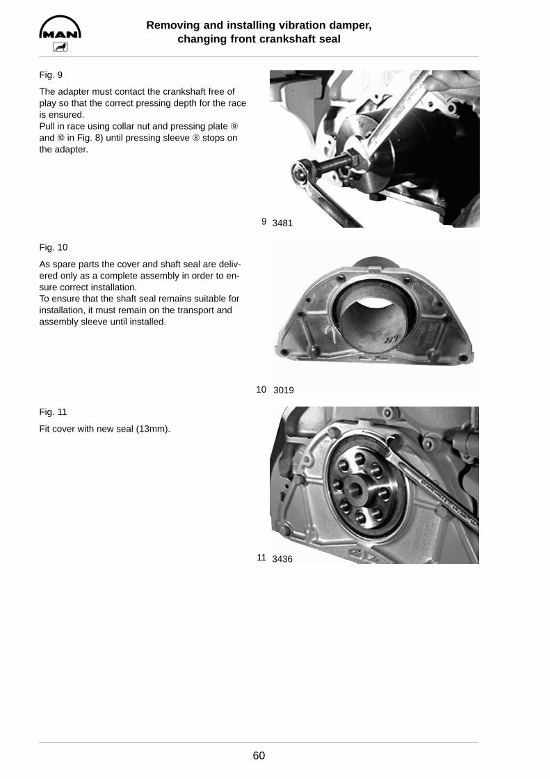
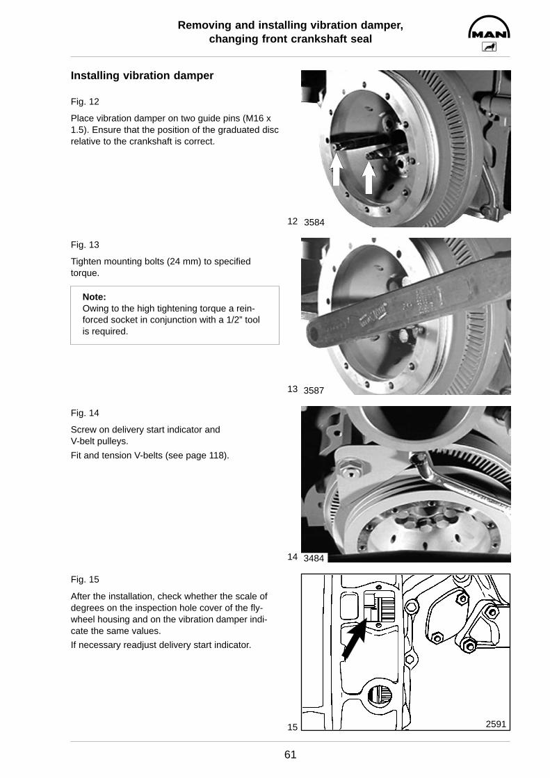
Fig. 3
Loosen mounting bolts on vibration damper (24 mm).
Note:Owing to the high tightening torque a rein-forced socket in conjunction with a 1/2” toolis required. Prior to removal mark the posi-tion of the vibration damper relative to thecrankshaft. This will ensure that in the sub-sequent reassembly the graduated disc is incorrect position.
Fig. 4
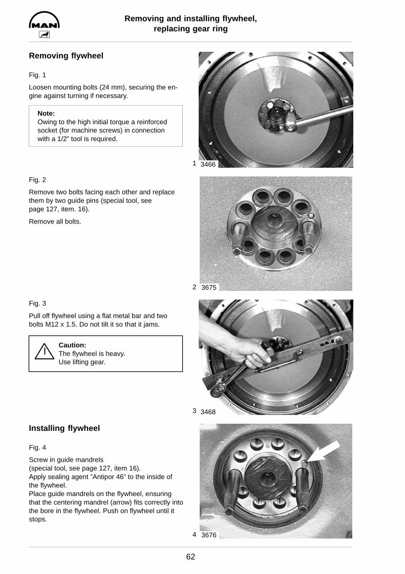
Remove vibration damper carefully.
Caution:The vibration damper is susceptible toshocks.
3475
3476
3477
3478

5
6
7
8
Removing and installing vibration damper,changing front crankshaft seal
59
Changing front crankshaft seal
Fig. 5
Remove cover (13 mm).Replace front crankshaft seal only as a completeunit, i.e. race and radial shaft seal.
Fig. 6
To remove the race, a puller (special tool, seepage 127, item 13) is necessary.
Fig. 7
Pull off race.
Fig. 8
Special tools are required for installing the race(see page 127, item 15).
Clean inner side of race and crankshaft stub. Coatcrankshaft stub with sealing agent ”Antipor 46”.
D Push race Æ and pressing sleeve Ç ontoadapter Â.
D Tighten spindle À in adapter  with nut Ã.
D Bolt adapter  to crankshaft.
3479
2718
3480
3091
9
10
11
Removing and installing vibration damper,changing front crankshaft seal
60
Fig. 9
The adapter must contact the crankshaft free ofplay so that the correct pressing depth for the raceis ensured.Pull in race using collar nut and pressing plate Èand É in Fig. 8) until pressing sleeve Ç stops onthe adapter.
Fig. 10
As spare parts the cover and shaft seal are deliv-ered only as a complete assembly in order to en-sure correct installation.To ensure that the shaft seal remains suitable forinstallation, it must remain on the transport andassembly sleeve until installed.
Fig. 11
Fit cover with new seal (13mm).
3481
3019
3436
12
13
14
15
Removing and installing vibration damper,changing front crankshaft seal
61
Installing vibration damper
Fig. 12
Place vibration damper on two guide pins (M16 x1.5). Ensure that the position of the graduated discrelative to the crankshaft is correct.
Fig. 13
Tighten mounting bolts (24 mm) to specifiedtorque.
Note:Owing to the high tightening torque a rein-forced socket in conjunction with a 1/2” toolis required.
Fig. 14
Screw on delivery start indicator and V-belt pulleys.
Fit and tension V-belts (see page 118).
Fig. 15
After the installation, check whether the scale ofdegrees on the inspection hole cover of the fly-wheel housing and on the vibration damper indi-cate the same values.
If necessary readjust delivery start indicator.
3584
3587
3484
2591
1
2
3
4
Removing and installing flywheel,replacing gear ring
62
Removing flywheel
Fig. 1
Loosen mounting bolts (24 mm), securing the en-gine against turning if necessary.
Note:Owing to the high initial torque a reinforcedsocket (for machine screws) in connectionwith a 1/2” tool is required.
Fig. 2
Remove two bolts facing each other and replacethem by two guide pins (special tool, see page 127, item. 16).
Remove all bolts.
Fig. 3
Pull off flywheel using a flat metal bar and twobolts M12 x 1.5. Do not tilt it so that it jams.
Caution:The flywheel is heavy. Use lifting gear.
Installing flywheel
Fig. 4
Screw in guide mandrels (special tool, see page 127, item 16).Apply sealing agent ”Antipor 46” to the inside ofthe flywheel.Place guide mandrels on the flywheel, ensuringthat the centering mandrel (arrow) fits correctly intothe bore in the flywheel. Push on flywheel until itstops.
3466
3675
3468
3676

5
6
7
Removing and installing flywheel,replacing gear ring
63
Fig. 5
Lightly oil new mounting bolts (elasticated bolts) ,screw them in and tighten alternately on oppositesides of the ring gear to specified torque (see ”Engineering S Data S Setting values”).
Changing starter gear ring
Fig. 6
Remove flywheel.Drill a hole in starter gear ring and snap it using achisel.
Caution:Take care not to damage the flywheel.
Fig. 7
Heat new starter gear ring up to approx. 200_C to230_C and press on until it stops.Check axial runout and compare with max. permis-sible value.
3470
3471
2716
1
2
3
Removing and installing crankshaft seal(flywheel end)
64
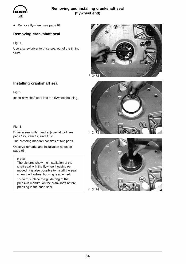
D Remove flywheel, see page 62
Removing crankshaft seal
Fig. 1
Use a screwdriver to prise seal out of the timingcase.
Installing crankshaft seal
Fig. 2
Insert new shaft seal into the flywheel housing.
Fig. 3
Drive in seal with mandrel (special tool, see page 127, item 12) until flush.
The pressing mandrel consists of two parts.
Observe remarks and installation notes on page 66.
Note:The pictures show the installation of theshaft seal with the flywheel housing re-moved. It is also possible to install the sealwhen the flywheel housing is attached.
To do this, place the guide ring of thepress–in mandrel on the crankshaft beforepressing in the shaft seal.
3472
3473
3474
1
2
3
4
Exchanging bearing race
65
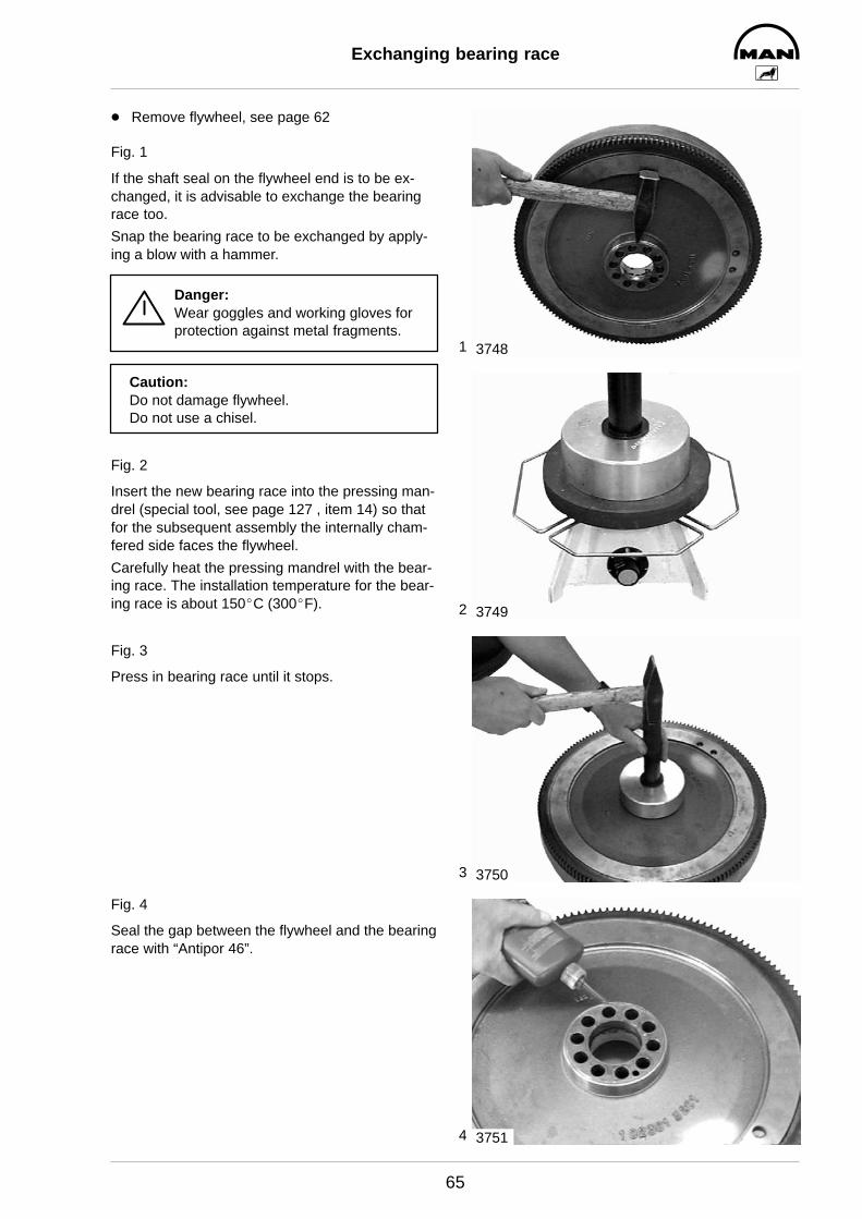
D Remove flywheel, see page 62
Fig. 1
If the shaft seal on the flywheel end is to be ex-changed, it is advisable to exchange the bearingrace too.
Snap the bearing race to be exchanged by apply-ing a blow with a hammer.
Danger:Wear goggles and working gloves forprotection against metal fragments.
Caution:Do not damage flywheel.Do not use a chisel.
Fig. 2
Insert the new bearing race into the pressing man-drel (special tool, see page 127 , item 14) so thatfor the subsequent assembly the internally cham-fered side faces the flywheel.
Carefully heat the pressing mandrel with the bear-ing race. The installation temperature for the bear-ing race is about 150_C (300_F).
Fig. 3
Press in bearing race until it stops.
Fig. 4
Seal the gap between the flywheel and the bearingrace with “Antipor 46”.
3748
3749
3750
3751

Crankshaft seals
66
General remarks on crankshaft seals
As a matter of fundamental principle only radial shaft seals made of polytetrafluor ethylene (PTFE), tradename Teflon, are used.
PTFE seals can be easily distinguished from the former elastomer seals by their considerably wider andflat sealing lip which is no longer pre-loaded by means of a tubular spring.
As a result of its relatively high initial stress the sealing lip curves inwards. For this reason PTFE seals aresupplied on transport sleeves. They must not be taken off the sleeves before they are needed so as to en-sure that they can still be installed. Great care should be taken when fitting lip seals. Even the slightestdamage to the seal would result in leaks.
The sealing lip and the race of the flywheel must not be coated with oil or any other lubricants.
When installing a new seal always replace the race too.
Assembly instructions for crankshaft seals
D The PTFE seal must be absolutely free of oil and grease when installed. Even the slightest traces of oilon the race or the sealing ring cause leakage.
D Before installing the race remove oil, grease and anticorrosion agent from it. All cleaning agents nor-mally used in workshops can be used for this purpose.
D A PTFE seal soiled with oil or grease is useless. Cleaning it is not permissible.
D The PTFE seal must never be stored without the transport sleeve delivered with it. Even after a storageperiod of only 30 minutes without the transport sleeve it looses its initial stress and becomes useless.

1
2
3
4
Removing and installing intake manifold
67
D Drain coolant, see page 37D Remove intercooler, see page 77
Note:When carrying out work on the intake sys-tem, ensure meticulous cleanliness to pre-vent dirt and foreign matter from penetratinginto the system.
Removing intake manifold
Fig. 1
Remove hose connection from LDA.
Fig. 2
Remove the mounting bolts from the intake pipe (13 mm).
Fig. 3
Take off intake pipe.
Installing intake manifold
Fig. 4
Place intake manifold with new seals in position.Tighten mounting bolts to the specified torque.Ensure that the seals are correctly seated.
3490
3491
3492
3493
1
2
3
4
Removing and installing exhaust manifold
68
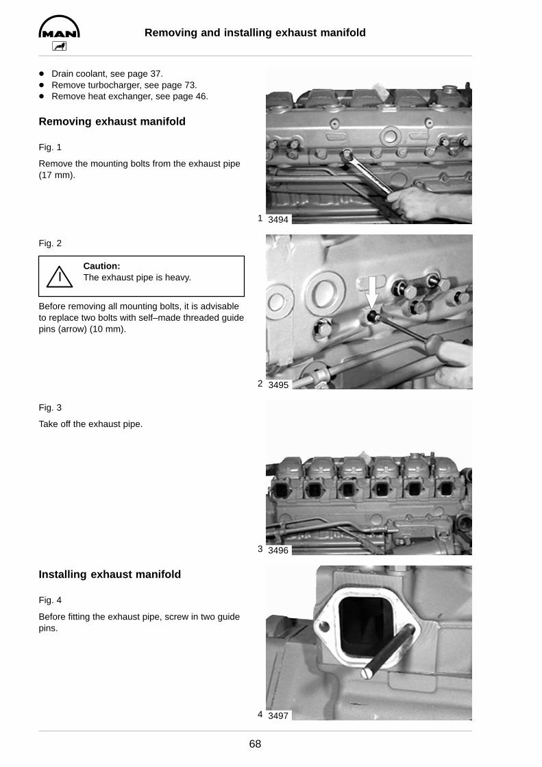
D Drain coolant, see page 37.D Remove turbocharger, see page 73.D Remove heat exchanger, see page 46.
Removing exhaust manifold
Fig. 1
Remove the mounting bolts from the exhaust pipe(17 mm).
Fig. 2
Caution:The exhaust pipe is heavy.
Before removing all mounting bolts, it is advisableto replace two bolts with self–made threaded guidepins (arrow) (10 mm).
Fig. 3
Take off the exhaust pipe.
Installing exhaust manifold
Fig. 4
Before fitting the exhaust pipe, screw in two guidepins.
3494
3495
3496
3497
5
6
Removing and installing exhaust manifold
69
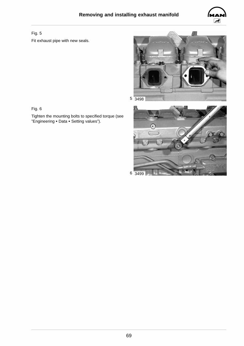
Fig. 5
Fit exhaust pipe with new seals.
Fig. 6
Tighten the mounting bolts to specified torque (see”Engineering S Data S Setting values”).
3498
3499

Turbocharger, trouble shooting
70
Before removing the turbocharger carry out the following checks
Turbochargers are frequently exchanged if the oil consumption is too high, the output too low or the intakeand/or exhaust gas noises appear to be abnormal. Subsequent inspections by the manufacturer of the sup-posedly defective parts frequently prove the turbochargers to be in order.
To ensure that only defective turbochargers will be exchanged in future, the following checks are to be car-ried out beforehand:
If the oil consumption is too high
– Check air filter for contamination,– ensure that the engine room ventilation is adequate,– check intake pipe for cross section reduction (owing e.g. to damage, contamination).
These causes lead to higher oil consumption owing to the increased vacuum on the intake side of the com-pressor.
– Check outside of turbocharger for oil traces.
Oil consumption caused directly by turbocharger depends on the bearing wear and results in relatively earlymechanical damage.
If engine performance is not satisfactory
Correct adjustment of the
– delivery start,– valve clearance,– speed adjustment (to full load stop).
In addition, the following are to be checked:
– the compression,– the air filters for contamination,– the charge-air pressure,– the pressure in the inlet chamber of the injection pump,– the exhaust back pressure.
If you do not detect any possible cause in the above checks, check the turbocharger for:
– Carbonization in the turbine area, which impairs the movement of the wheel assembly (can be eliminated by axial movement).
– Dirt in the compressor area.– Damage caused by foreign objects.– Scraping of the turbine rotor on the housing.
If a considerable amount of dirt has accumulated, clean the compressor end and check the bearing clearance.
Important! Do not damage the aluminium compressor wheel.
Turbocharger, trouble shooting
71
When there is unusual intake or exhaust noise
– Check the intake and exhaust system in the area of the charger group.– Defective gaskets can lead you to think the turbocharger is defective. Replace them.– If there are still unusual noises, check the bearing clearance.– Turbochargers in good working order do not make any excessive noise.
Oil accumulation in charge-air lines and the intercooler
A small amount of oil collects in the charge-air system. This is supposed to happen, is caused by oil mist,and is desirable. The oil mist is required to lubricate the intake valve seats.
If more oil accumulates than usual, that is, if oil pockets develop in the lower air box of the intercooler, forexample, this can lead to oil disintegration or uncontrolled raising of the engine speed when the oil is sepa-rated. In such cases, you must eliminate the cause.
Possible causes:
– The engine is overfilled with oil.– Check whether the correct dipstick and guide pipe combination is installed.– The engine oil used is unsuitable (see publication ”Fuels, Lubricants, Coolants for Industrial and Marine
Diesel Engines”).– The engine is being run on impermissibly steep inclines.– The crankcase pressure is to high. This may be caused by a defective oil separator valve or piston ring
wear.
Compressor carbonization
This can occur when the charge-air temperature is permanently high, for example when the engine isconstantly run at full load.
Carbonization lowers the charging pressure but does not negatively affect performance or acceleration.
Carbonization can lead to increased exhaust clouding.
If exhaust emissions test values are no longer met:
– Remove the compressor housing, being careful not to let it get jammed. If it gets jammed, the compres-sor wheel blades may get damaged or bent, and the resultant imbalance can ruin the turbocharger.
– Remove carbonization in the compressor housing with a suitable cleaning agent.
Caution:Never spray in cleaning agent while the engine is running.– ineffective– dangerous
In problem cases, use oil types that are less likely to lead to compressor carbonisation (see publication”Fuels, Lubricants, Coolants for Industrial and Marine Diesel Engines”)
1
2
Checking the charge-air pressure
72
Why must the charge-air pressure be checked?
Sufficient charge-air pressure is indispensable for full power output and clean combustion.
Checking the charge-air pressure helps detect damage to the turbocharger, operating faults in the waste-gate and leaks in the intercooler and in the charge-air pipes.
Extreme operating conditions (full-load operation and high air temperature) and the use of unsuitable en-gine oils (also see publication ”Fuels, Lubricants, Coolants for Industrial and Marine Diesel Engines”) maycause deposits on the compressor as well as in the intercooler, which results in a reduction in charge-airpressure.
Preconditions for the measurement:
The delivery start and the valve clearance must be set as specified, and the engine must be at operating
temperature.
How high must the charge-air pressure be?
A general set-point value for the charge-air pressure cannot be given. Values ascertained on the test bedought not to be used for comparison, as the respective installation conditions are decisive. The value whichwas ascertained when the ship was commissioned and was noted in the commissioning report is to beused as the set-point value.
What must be observed during the measurement?
Owing to various atmospheric reference conditions during the measurements and to tolerances of the pres-sure gauges used, deviations of max. ± 100 hPa (± 100 mbar) are permissible.
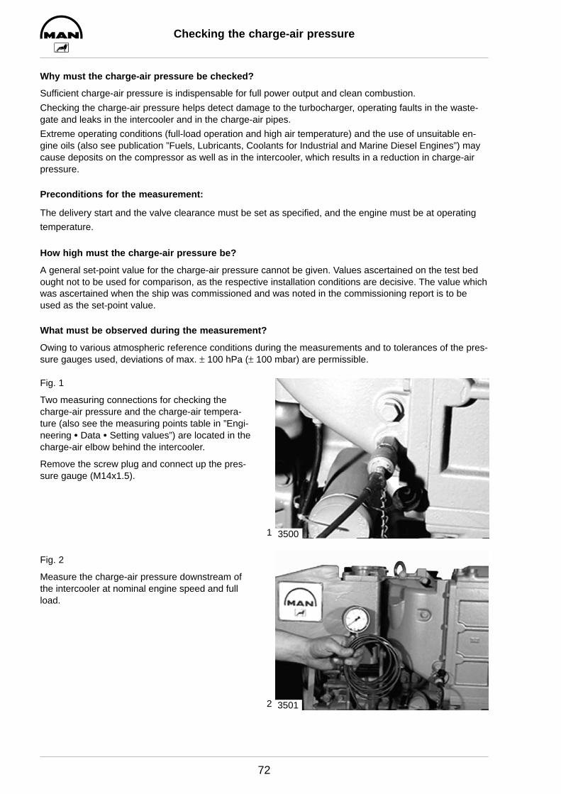
Fig. 1
Two measuring connections for checking thecharge-air pressure and the charge-air tempera-ture (also see the measuring points table in ”Engi-neering S Data S Setting values”) are located in thecharge-air elbow behind the intercooler.
Remove the screw plug and connect up the pres-sure gauge (M14x1.5).
Fig. 2
Measure the charge-air pressure downstream ofthe intercooler at nominal engine speed and fullload.
3500
3501

1
2
3
4
Removing and installing turbocharger
73
Removing turbocharger
D Drain coolant, see page 37
Fig. 1
Take off air filter. Remove the hose from the crank-case breather.Take off air filter. Remove the hose from the crank-case breather.Remove the air intake funnel and the connectionfrom the compressor to the charge-air elbow.Remove the hose from the wastegate.
Fig. 2
Remove oil supply and return lines (17 mm).
Fig. 3
Remove the coolant supply line from the turbo-charger.
Fig. 4
Remove the mounting bolts from the exhaust man-ifold (17 mm).
Remove the coolant line between the turbine hous-ing and the exhaust manifold.
3502
3503
3504
3505

5
6
7
Removing and installing turbocharger
74
Fig. 5
Take off exhaust manifold.
Fig. 6
Remove the four (self–locking) nuts from the turbo-charger flange (17 mm).
Take off turbocharger.
Note:Ensure meticulous cleanliness when puttingthe turbocharger aside to prevent dirt andforeign matter from penetrating into the inte-rior of the turbocharger.
Installing turbocharger
Fig. 7
The turbocharger is assembled in reverse order.When assembling, use new seals and new self–locking nuts.Before connecting up the oil supply line, fill bearinghousing up with clean engine oil.Check all connections for leaks and tension.
3506
3508
3509
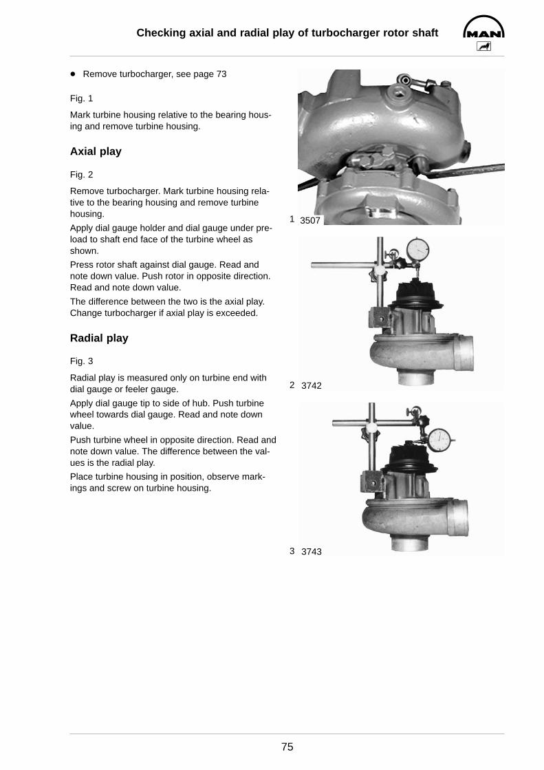
1
2
3
Checking axial and radial play of turbocharger rotor shaft
75
D Remove turbocharger, see page 73
Fig. 1
Mark turbine housing relative to the bearing hous-ing and remove turbine housing.
Axial play
Fig. 2
Remove turbocharger. Mark turbine housing rela-tive to the bearing housing and remove turbinehousing.
Apply dial gauge holder and dial gauge under pre-load to shaft end face of the turbine wheel asshown.
Press rotor shaft against dial gauge. Read andnote down value. Push rotor in opposite direction.Read and note down value.
The difference between the two is the axial play.Change turbocharger if axial play is exceeded.
Radial play
Fig. 3
Radial play is measured only on turbine end withdial gauge or feeler gauge.
Apply dial gauge tip to side of hub. Push turbinewheel towards dial gauge. Read and note downvalue.
Push turbine wheel in opposite direction. Read andnote down value. The difference between the val-ues is the radial play.
Place turbine housing in position, observe mark-ings and screw on turbine housing.
3507
3742
3743
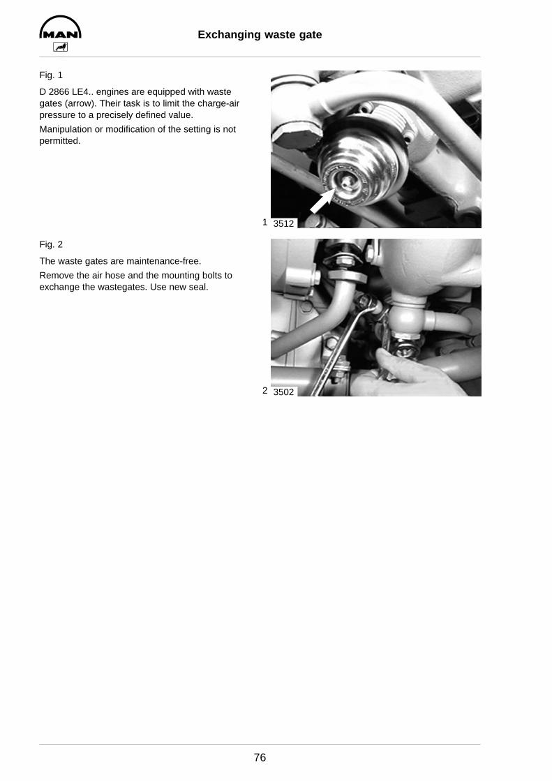
1
2
Exchanging waste gate
76
Fig. 1
D 2866 LE4.. engines are equipped with wastegates (arrow). Their task is to limit the charge-airpressure to a precisely defined value.
Manipulation or modification of the setting is notpermitted.
Fig. 2
The waste gates are maintenance-free.
Remove the air hose and the mounting bolts toexchange the wastegates. Use new seal.
3512
3502
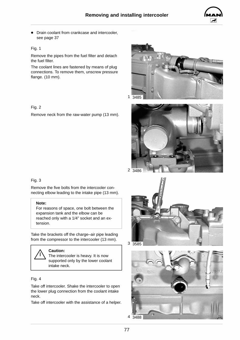
1
2
3
4
Removing and installing intercooler
77
D Drain coolant from crankcase and intercooler,see page 37
Fig. 1
Remove the pipes from the fuel filter and detachthe fuel filter.
The coolant lines are fastened by means of plugconnections. To remove them, unscrew pressureflange. (10 mm).
Fig. 2
Remove neck from the raw-water pump (13 mm).
Fig. 3
Remove the five bolts from the intercooler con-necting elbow leading to the intake pipe (13 mm).
Note:For reasons of space, one bolt between theexpansion tank and the elbow can bereached only with a 1/4” socket and an ex-tension.
Take the brackets off the charge–air pipe leadingfrom the compressor to the intercooler (13 mm).
Caution:The intercooler is heavy. It is nowsupported only by the lower coolantintake neck.
Fig. 4
Take off intercooler. Shake the intercooler to openthe lower plug connection from the coolant intakeneck.
Take off intercooler with the assistance of a helper.
3485
3486
3585
3488
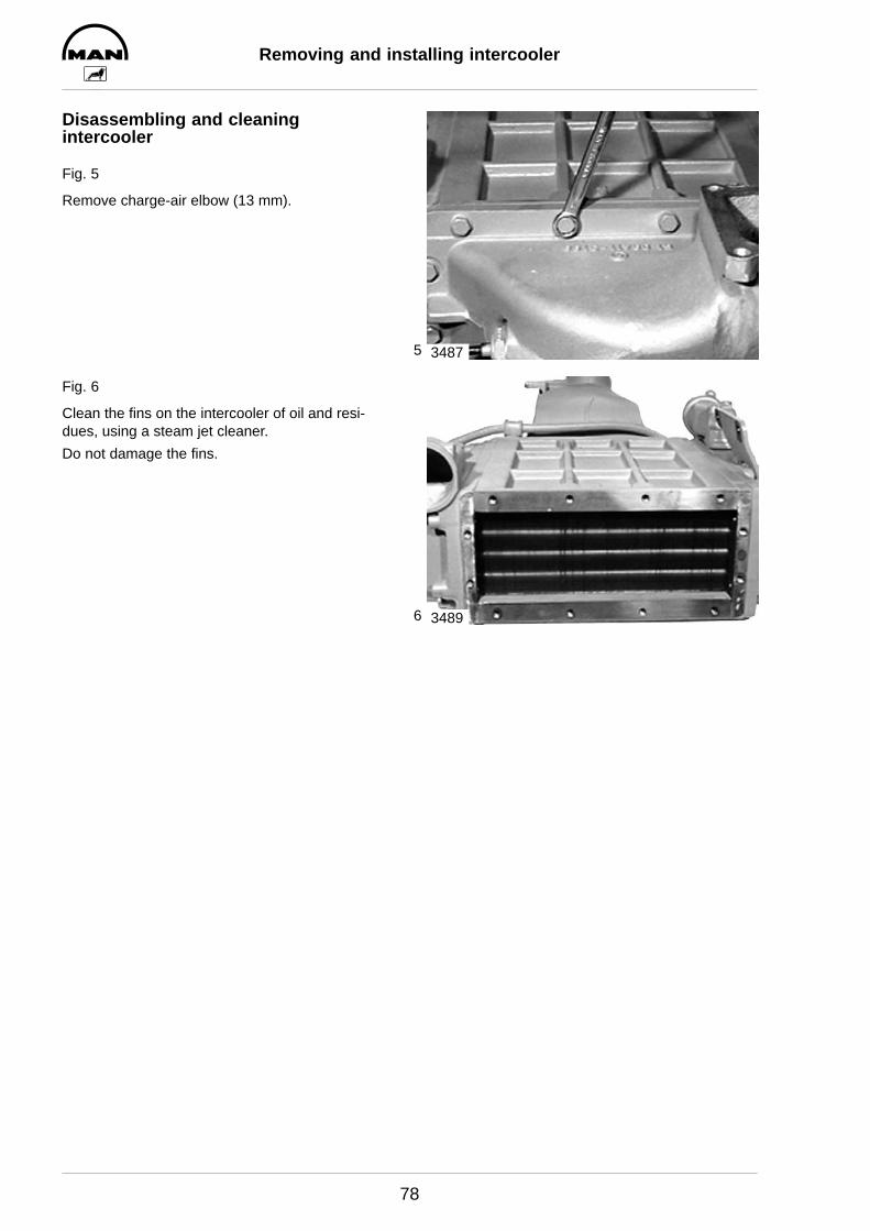
5
6
Removing and installing intercooler
78
Disassembling and cleaning intercooler
Fig. 5
Remove charge-air elbow (13 mm).
Fig. 6
Clean the fins on the intercooler of oil and resi-dues, using a steam jet cleaner.
Do not damage the fins.
3487
3489

1
2
3
4
Removing and installing cylinder head
79
Removing cylinder head
D Drain coolant, see page 37
Note:The intake and exhaust pipes need not bedetached for removing the cylinder head.
Fig. 1
Remove the injection nozzles, see page 30.
Take off the cylinder head covers (13 mm).
Fig. 2
Remove the coolant bleed pipe.
Fig. 3
Back off valve adjusting screws.Loosen mounting bolts of rocker arm bracket(17mm).
Fig. 4
Remove rocker arm bracket.
3406
3513
3514
3515

5
6
7
8
Removing and installing cylinder head
80
Fig. 5
Take out push rods.
Fig. 6
Remove cylinder head bolts in reverse order oftightening.
Note:Use reinforced socket (screw–driving ma-chine) to loosen and tighten the cylinderhead bolts.
Fig. 7
Remove the mounting bolts from the intake andexhaust pipes for the respective cylinder head.
Also remove those intake and exhaust pipe bolts,which are adjacent to the respective cylinder head.
This will reduce the tension on the cylinder head,and the head can be taken off more easily.
Fig. 8
Take off cylinder head and cylinder head gasket.
Check whether cylinder head sealing face and cyl-inder block are plane using a straight edge.Non-plane cylinder heads can be remilled 1 mm.Notice specified projection of injection nozzles andvalve recess (see ”Engineering S Data S Settingvalues”).
Note:Check cylinder heads for cracks.
3516
3517
3518
3705
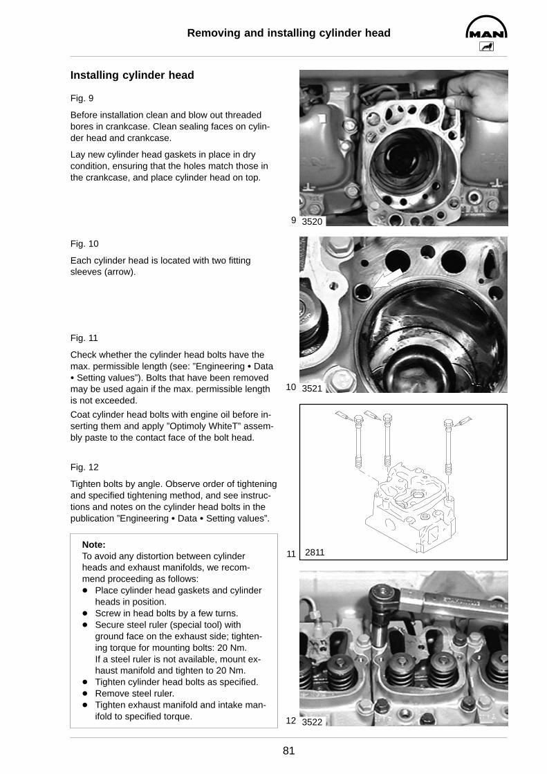
9
10
11
12
Removing and installing cylinder head
81
Installing cylinder head
Fig. 9
Before installation clean and blow out threadedbores in crankcase. Clean sealing faces on cylin-der head and crankcase.
Lay new cylinder head gaskets in place in drycondition, ensuring that the holes match those inthe crankcase, and place cylinder head on top.
Fig. 10
Each cylinder head is located with two fittingsleeves (arrow).
Fig. 11
Check whether the cylinder head bolts have themax. permissible length (see: ”Engineering S DataS Setting values”). Bolts that have been removedmay be used again if the max. permissible lengthis not exceeded.
Coat cylinder head bolts with engine oil before in-serting them and apply ”Optimoly WhiteT” assem-bly paste to the contact face of the bolt head.
Fig. 12
Tighten bolts by angle. Observe order of tighteningand specified tightening method, and see instruc-tions and notes on the cylinder head bolts in thepublication ”Engineering S Data S Setting values”.
Note:To avoid any distortion between cylinderheads and exhaust manifolds, we recom-mend proceeding as follows:D Place cylinder head gaskets and cylinder
heads in position.D Screw in head bolts by a few turns.D Secure steel ruler (special tool) with
ground face on the exhaust side; tighten-ing torque for mounting bolts: 20 Nm.If a steel ruler is not available, mount ex-haust manifold and tighten to 20 Nm.
D Tighten cylinder head bolts as specified.D Remove steel ruler.D Tighten exhaust manifold and intake man-
ifold to specified torque.
3520
3521
2811
3522
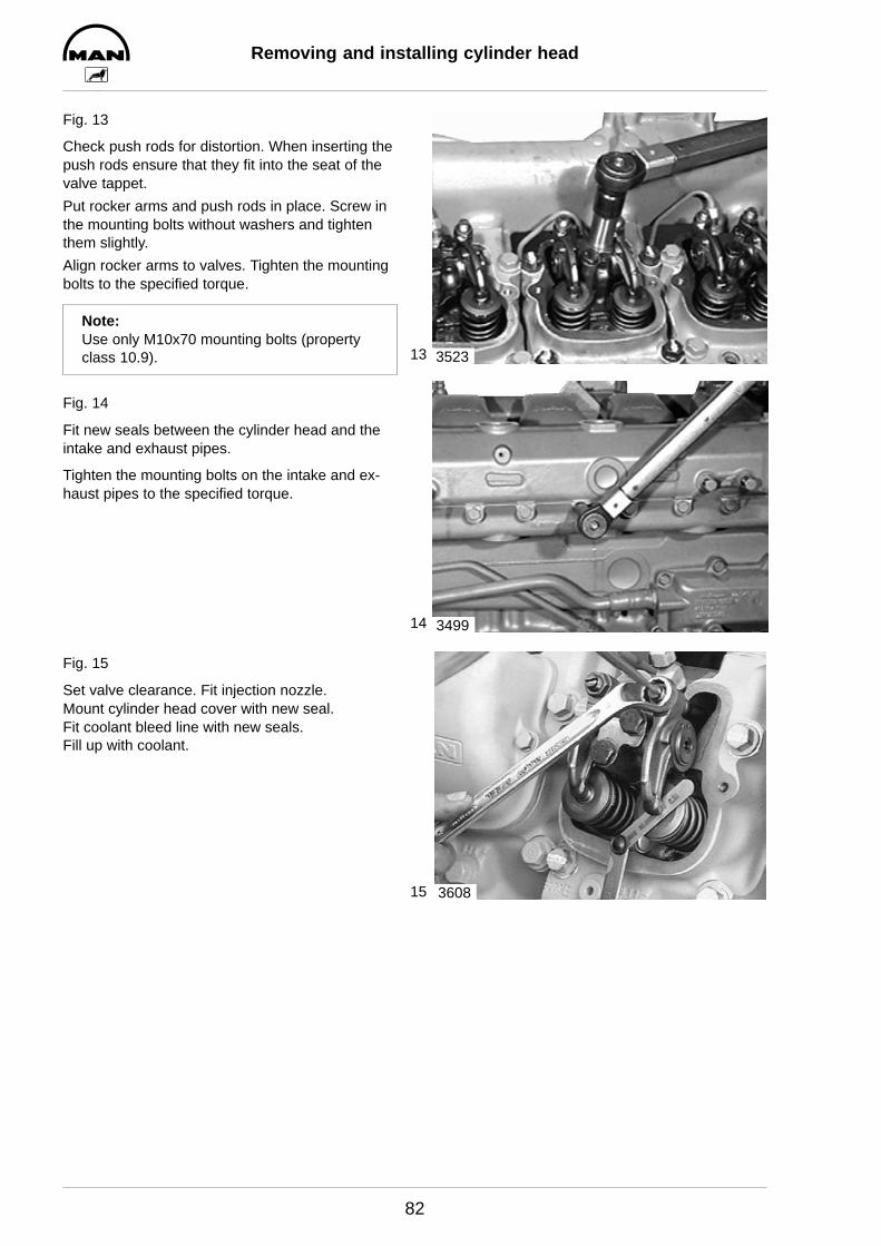
13
14
15
Removing and installing cylinder head
82
Fig. 13
Check push rods for distortion. When inserting thepush rods ensure that they fit into the seat of thevalve tappet.
Put rocker arms and push rods in place. Screw inthe mounting bolts without washers and tightenthem slightly.
Align rocker arms to valves. Tighten the mountingbolts to the specified torque.
Note:Use only M10x70 mounting bolts (propertyclass 10.9).
Fig. 14
Fit new seals between the cylinder head and theintake and exhaust pipes.
Tighten the mounting bolts on the intake and ex-haust pipes to the specified torque.
Fig. 15
Set valve clearance. Fit injection nozzle.Mount cylinder head cover with new seal.Fit coolant bleed line with new seals.Fill up with coolant.
3523
3499
3608

Removing and installing cylinder head
83
General notes:
The sealing effect of the cylinder head gasket largely depends on whether the required initial tension for thecylinder head bolts is reached and maintained.
Use calibrated torque wrenches to tighten the cylinder head bolts. When the specified final torque is appliedit must be maintained for at least 5 seconds. When using snap-type torque wrenches tighten bolts graduallysince otherwise the torque selected will not be fully transferred to the bolts.
Observe notes on usability of cylinder head bolts, order of tightening and specified tightening method inpublication ”Engineering S Data S Setting values”.
Tightening
”Tightening” is defined as the first–time tightening of newly fitted bolts that have not been tightened after arepair, e.g. changing the cylinder head gasket. Tighten cylinder head bolts while the engine is cold, i.e. thecrankcase is warm to the touch or colder.
Before inserting the cylinder head bolts, apply engine oil to the thread (not to the threaded hole) and ”Opti-moly White T” assembly paste to the contact faces of the bolt heads.Do not use oil or oil additives containing MoS2.If the bolts are not oiled, a significant amount of the tightening torque is converted into friction and thus lostfor the bolt pretensioning.
D To position cylinder heads, tighten cylinder head bolts only lightly.
D Align cylinder heads by screwing on the steel ruler (special tool). If a steel ruler is not available, use ex-haust or intake manifold.
D Tighten bolts in specified order and to specified torque / tightening angle in steps.
Caution:If during initial tightening some bolts are excessively tightened, the cylinder head will be distorted. This distortion cannot be cancelled out by continuing to tighten according to the instructions.

1
2
3
4
Setting valve clearance
84
Fig. 1
Remove cylinder head cover (13mm).
Figs. 2 and 3
Use barring device to turn engine so that the pis-ton in the cylinder to be set is at TDC and the twovalves are closed. At this point both inlet and ex-haust valves will be open i.e. valves overlap.
Note:As far as possible turn engine only in direc-tion of rotation (anti-clockwise as seen whenlooking at the flywheel) in order to preventthe direction of rotation of the raw waterpump impeller being reversed.
Fig. 4
Arrangement of cylinders and valves
I Engine front endII Flywheel sideA Exhaust valveE Inlet valve
3389
3390
Valves are in crossover in cylinder
1 5 3 6 2 4
6 2 4 1 5 3
Set valves in the cylinder
I IIE A E A E A E A E A E A1 2 3 4 5 6
3607
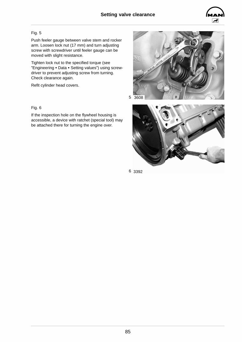
5
6
Setting valve clearance
85
Fig. 5
Push feeler gauge between valve stem and rockerarm. Loosen lock nut (17 mm) and turn adjustingscrew with screwdriver until feeler gauge can bemoved with slight resistance.
Tighten lock nut to the specified torque (see ”Engineering S Data S Setting values”) using screw-driver to prevent adjusting screw from turning.Check clearance again.
Refit cylinder head covers.
Fig. 6
If the inspection hole on the flywheel housing isaccessible, a device with ratchet (special tool) maybe attached there for turning the engine over.
3608
3392

1
2
3
4
Disassembling and assembling rocker arms
86
Fig. 1
Remove rocker arms.
Fig. 2
Unclip circlip.
Fig. 3
Take rocker arms off the rocker arm shaft.
Note:If the rocker arm bearing bushes have to beexchanged, ready-to-install new or recondi-tioned rocker arms are to be used.
Fig. 4
Before fitting the rocker arms (1) to the rocker armshafts and brackets, coat sliding faces (2 and 3)with Optimoly Paste White T. This applies to bothnew and already used parts.
3524
3525
3526
2812
1 2
23
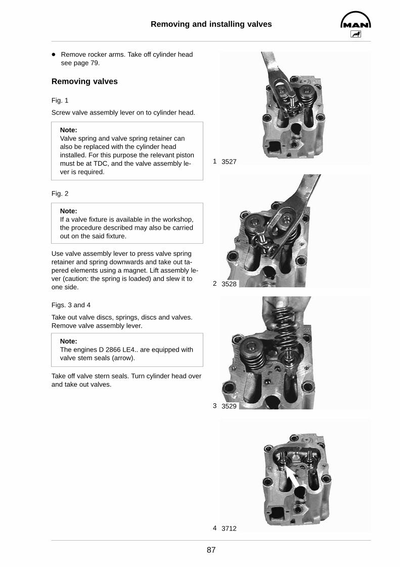
1
2
3
4
Removing and installing valves
87
D Remove rocker arms. Take off cylinder headsee page 79.
Removing valves
Fig. 1
Screw valve assembly lever on to cylinder head.
Note:Valve spring and valve spring retainer canalso be replaced with the cylinder headinstalled. For this purpose the relevant pistonmust be at TDC, and the valve assembly le-ver is required.
Fig. 2
Note:If a valve fixture is available in the workshop,the procedure described may also be carriedout on the said fixture.
Use valve assembly lever to press valve springretainer and spring downwards and take out ta-pered elements using a magnet. Lift assembly le-ver (caution: the spring is loaded) and slew it toone side.
Figs. 3 and 4
Take out valve discs, springs, discs and valves.Remove valve assembly lever.
Note:The engines D 2866 LE4.. are equipped withvalve stem seals (arrow).
Take off valve stern seals. Turn cylinder head overand take out valves.
3527
3528
3529
3712
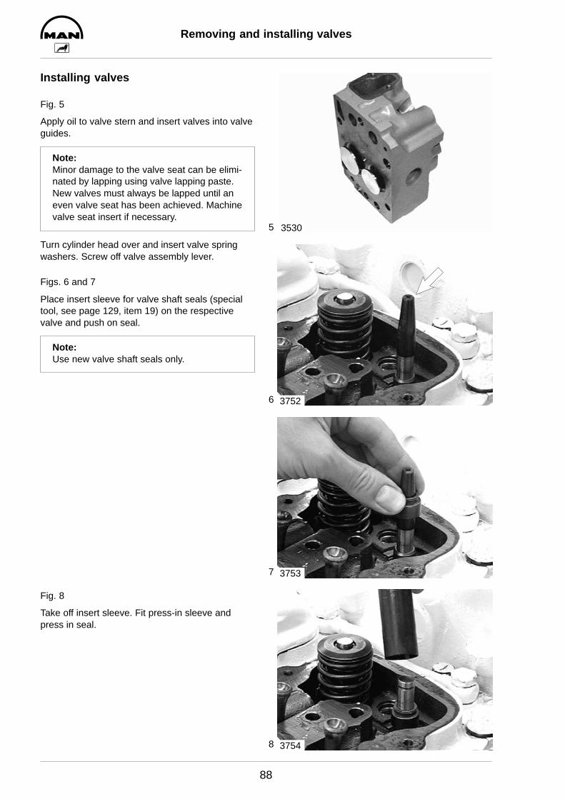
5
6
7
8
Removing and installing valves
88
Installing valves
Fig. 5
Apply oil to valve stern and insert valves into valveguides.
Note:Minor damage to the valve seat can be elimi-nated by lapping using valve lapping paste.New valves must always be lapped until aneven valve seat has been achieved. Machinevalve seat insert if necessary.
Turn cylinder head over and insert valve springwashers. Screw off valve assembly lever.
Figs. 6 and 7
Place insert sleeve for valve shaft seals (specialtool, see page 129, item 19) on the respectivevalve and push on seal.
Note:Use new valve shaft seals only.
Fig. 8
Take off insert sleeve. Fit press-in sleeve andpress in seal.
3530
3752
3753
3754
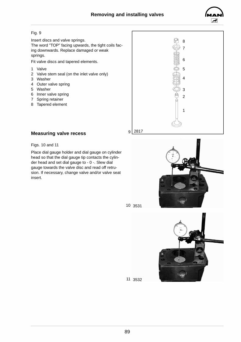
9
10
11
Removing and installing valves
89
Fig. 9
Insert discs and valve springs.The word ”TOP” facing upwards, the tight coils fac-ing downwards. Replace damaged or weaksprings.
Fit valve discs and tapered elements.
1 Valve2 Valve stem seal (on the inlet valve only)3 Washer4 Outer valve spring5 Washer6 Inner valve spring7 Spring retainer8 Tapered element
Measuring valve recess
Figs. 10 and 11
Place dial gauge holder and dial gauge on cylinderhead so that the dial gauge tip contacts the cylin-der head and set dial gauge to - 0 -. Slew dialgauge towards the valve disc and read off retru-sion. If necessary, change valve and/or valve seatinsert.
1
2
3
4
5
6
7
8
2817
3531
3532

1
2
Removing and installing valve guides
90
D For removing and installing cylinder head, see page 79
D For removing and installing valves, see page 87
Fig. 1
Press valve guide out of the combustion chamberside using pressing mandrel (special tool, seepage 129, item 20).
Oil new valve guide and drive/press it into the cyl-inder head using pressing mandrel and spacersleeve (special tool).
Fig. 2
The valve guides vary only in length.
1 Inlet = long guide2 Exhaust = short guide3 Press-in depth (see publication ”Engineering S
Data S Setting values”).
The correct press-in depth is obtained by using thespacer sleeve.Afterwards ream valve guide to specified dimension.
Note:When the valve guides have been changed,the valve seats too must be reworked (seetechnical data and manufacturers’ instruc-tions for valve seat lathes found in individualworkshops).
3533
3
21
2818
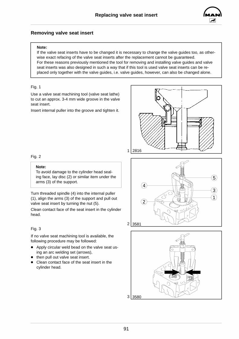
1
2
3
Replacing valve seat insert
91
Removing valve seat insert
Note:If the valve seat inserts have to be changed it is necessary to change the valve guides too, as other-wise exact refacing of the valve seat inserts after the replacement cannot be guaranteed.For these reasons previously mentioned the tool for removing and installing valve guides and valveseat inserts was also designed in such a way that if this tool is used valve seat inserts can be re-placed only together with the valve guides, i.e. valve guides, however, can also be changed alone.
Fig. 1
Use a valve seat machining tool (valve seat lathe)to cut an approx. 3-4 mm wide groove in the valveseat insert.
Insert internal puller into the groove and tighten it.
Fig. 2
Note:To avoid damage to the cylinder head seal-ing face, lay disc (2) or similar item under thearms (3) of the support.
Turn threaded spindle (4) into the internal puller(1), align the arms (3) of the support and pull outvalve seat insert by turning the nut (5).
Clean contact face of the seat insert in the cylinderhead.
Fig. 3
If no valve seat machining tool is available, thefollowing procedure may be followed:
D Apply circular weld bead on the valve seat us-ing an arc welding set (arrows),
D then pull out valve seat insert.D Clean contact face of the seat insert in the
cylinder head.
2816
3581
12
34
5
3580
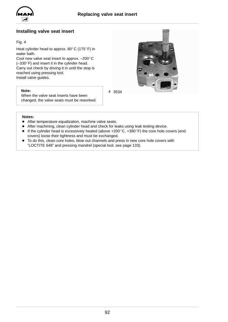
4
Replacing valve seat insert
92
Installing valve seat insert
Fig. 4
Heat cylinder head to approx. 80_C (175_F) in water bath.Cool new valve seat insert to approx. –200_C(–330_F) and insert it in the cylinder head.Carry out check by driving it in until the stop isreached using pressing tool.Install valve guides.
Note:When the valve seat inserts have beenchanged, the valve seats must be reworked.
3534
Notes:D After temperature equalization, machine valve seats.D After machining, clean cylinder head and check for leaks using leak testing device.D If the cylinder head is excessively heated (above +200_C, +390_F) the core hole covers (end
covers) loose their tightness and must be exchanged.D To do this, clean core holes, blow out channels and press in new core hole covers with
”LOCTITE 648” and pressing mandrel (special tool, see page 133).

1
2
3
Reworking valve seat
93
Reworking valve seat(with Mira precision valve seat machining device)
Fig. 1
1 Feed nut with mm scale2 Guide ball3 Jaccard lever4 Lubricating nipple5 Rotary head6 Hex socket screw7 Tool8 Guide mandrel9 Driving crank
10 Toggle switch11 Handle12 Lubricating nipple13 Mains connection14 Magnetic flange with coil15 Guide pipe16 Slewing arm
Fig. 2
Select suitable guide mandrel, screw it in with aspanner (12 mm) and tighten it.
Note:For extreme precision work the guide man-drel must fit snugly.
Select and insert the tool with the correspondingseat width and the corresponding seat angle.
Fig. 3
Set the tool with a setting gauge and tighten it withthe hex socket screw.
Insert unit with guide mandrel into the valve guide.
3358
1234567
8
10
9
11
1213
14
15
16
3360
3359
21

4
5
6
7
Reworking valve seat
94
Fig. 4
Release Jaccard lever, place magnetic flange flushon the clamping plate and set the height so thatthe tool does not contact the valve seat.Set toggle switch to position 1.Tighten the Jaccard lever.
Fig. 5
Machine the valve seat by turning the driving crankevenly in clockwise direction and simultaneouslyoperating the feed nut.
Caution:During the machining process turn the driv-ing crank vigorously and evenly but under nocircumstances against the direction of turn-ing, as otherwise the carbide cutting edgemay break.
Fig. 6
Once the valve seat has been expertly machined,reduce the working pressure of the tool by 2-3 rev-olutions without feed motion.During these revolutions turn the feed nut 2-3 rev-olutions back.Press toggle switch briefly to position 2 to lift themagnetic field.Now move the whole Mira unit out upwards andinsert it into the next valve guide, repeating thecentering operation.Use the same tool settings for all intake and allexhaust valve seats (see below).
Fig. 7
Observe specified seat angle.
1 Exhaust, total angle: 90_, tool setting: 45_2 Inlet, total angle: 120_, tool setting: 30_
Repeat the chip-removing machining process untilthe valve seat is clean and free of pores.
3361
3362
3363
2819
21
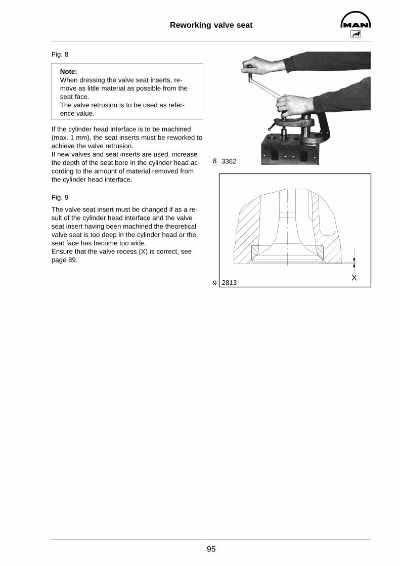
8
9
Reworking valve seat
95
Fig. 8
Note:When dressing the valve seat inserts, re-move as little material as possible from theseat face.The valve retrusion is to be used as refer-ence value.
If the cylinder head interface is to be machined(max. 1 mm), the seat inserts must be reworked toachieve the valve retrusion.If new valves and seat inserts are used, increasethe depth of the seat bore in the cylinder head ac-cording to the amount of material removed fromthe cylinder head interface.
Fig. 9
The valve seat insert must be changed if as a re-sult of the cylinder head interface and the valveseat insert having been machined the theoreticalvalve seat is too deep in the cylinder head or theseat face has become too wide.Ensure that the valve recess (X) is correct, seepage 89.
3362
2813X

2
2
3
4
Refacing valves
96
Fig. 1
Apply abrasive paste to tapered area on the valveseat.
Oil valve guide and insert valve.
Fig. 2
Use valve refacer to reface valve seat by applyingmoderate axial pressure and describing a turningmotion.
Important:Keep valve stem and valve guide free of abrasive paste.
Fig. 3
The valve seat must have a faultless, closed grind-ing pattern (2).The grinding pattern width is correct if the valveseat insert is in order.
1 Valve tapered area2 Valve seat
Fig. 4
1 Valve seat insert2 Valve3 Valve seat good4 Valve seat too wide
Note:Valve seats which are too wide tend to accu-mulate coking residues,
– valves become leaky –
Valve seats that are too small prevent rapiddischarge of heat from the valve disc to thecylinder head,
– valves burn –
3535
3591
2821
1 2
2822
1 2 1 2
43
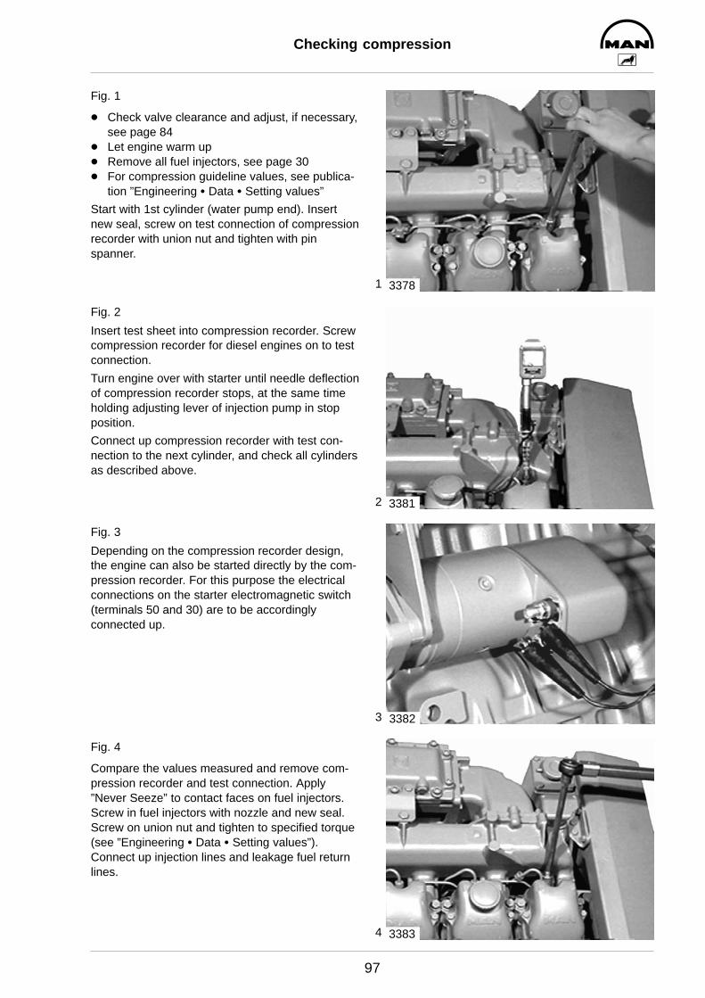
1
2
3
4
Checking compression
97
Fig. 1
D Check valve clearance and adjust, if necessary,see page 84
D Let engine warm upD Remove all fuel injectors, see page 30D For compression guideline values, see publica-
tion ”Engineering S Data S Setting values”
Start with 1st cylinder (water pump end). Insertnew seal, screw on test connection of compressionrecorder with union nut and tighten with pinspanner.
Fig. 2
Insert test sheet into compression recorder. Screwcompression recorder for diesel engines on to testconnection.
Turn engine over with starter until needle deflectionof compression recorder stops, at the same timeholding adjusting lever of injection pump in stopposition.
Connect up compression recorder with test con-nection to the next cylinder, and check all cylindersas described above.
Fig. 3
Depending on the compression recorder design,the engine can also be started directly by the com-pression recorder. For this purpose the electricalconnections on the starter electromagnetic switch(terminals 50 and 30) are to be accordingly connected up.
Fig. 4
Compare the values measured and remove com-pression recorder and test connection. Apply”Never Seeze” to contact faces on fuel injectors.Screw in fuel injectors with nozzle and new seal.Screw on union nut and tighten to specified torque(see ”Engineering S Data S Setting values”).Connect up injection lines and leakage fuel returnlines.
3378
3381
3382
3383
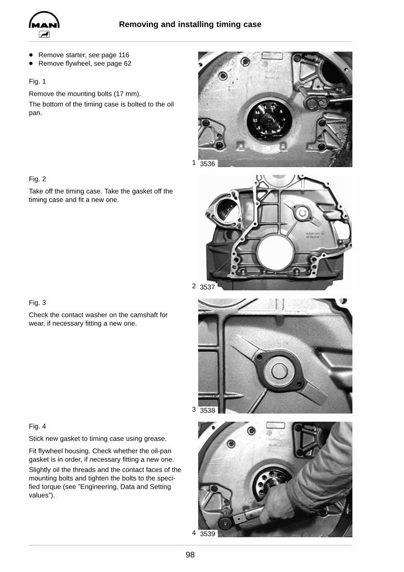
1
2
3
4
Removing and installing timing case
98
D Remove starter, see page 116D Remove flywheel, see page 62
Fig. 1
Remove the mounting bolts (17 mm).
The bottom of the timing case is bolted to the oilpan.
Fig. 2
Take off the timing case. Take the gasket off thetiming case and fit a new one.
Fig. 3
Check the contact washer on the camshaft forwear, if necessary fitting a new one.
Fig. 4
Stick new gasket to timing case using grease.
Fit flywheel housing. Check whether the oil-pangasket is in order, if necessary fitting a new one.
Slightly oil the threads and the contact faces of themounting bolts and tighten the bolts to the speci-fied torque (see ”Engineering, Data and Settingvalues”).
3536
3537
3538
3539
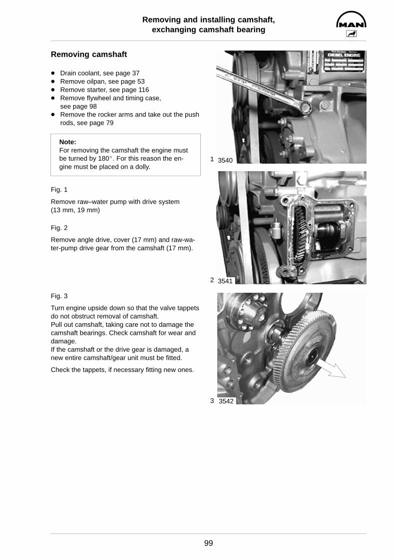
1
2
3
Removing and installing camshaft,exchanging camshaft bearing
99
Removing camshaft
D Drain coolant, see page 37D Remove oilpan, see page 53D Remove starter, see page 116D Remove flywheel and timing case,
see page 98D Remove the rocker arms and take out the push
rods, see page 79
Note:For removing the camshaft the engine mustbe turned by 180_. For this reason the en-gine must be placed on a dolly.
Fig. 1
Remove raw–water pump with drive system (13 mm, 19 mm)
Fig. 2
Remove angle drive, cover (17 mm) and raw-wa-ter-pump drive gear from the camshaft (17 mm).
Fig. 3
Turn engine upside down so that the valve tappetsdo not obstruct removal of camshaft.Pull out camshaft, taking care not to damage thecamshaft bearings. Check camshaft for wear anddamage.If the camshaft or the drive gear is damaged, anew entire camshaft/gear unit must be fitted.
Check the tappets, if necessary fitting new ones.
3540
3541
3542
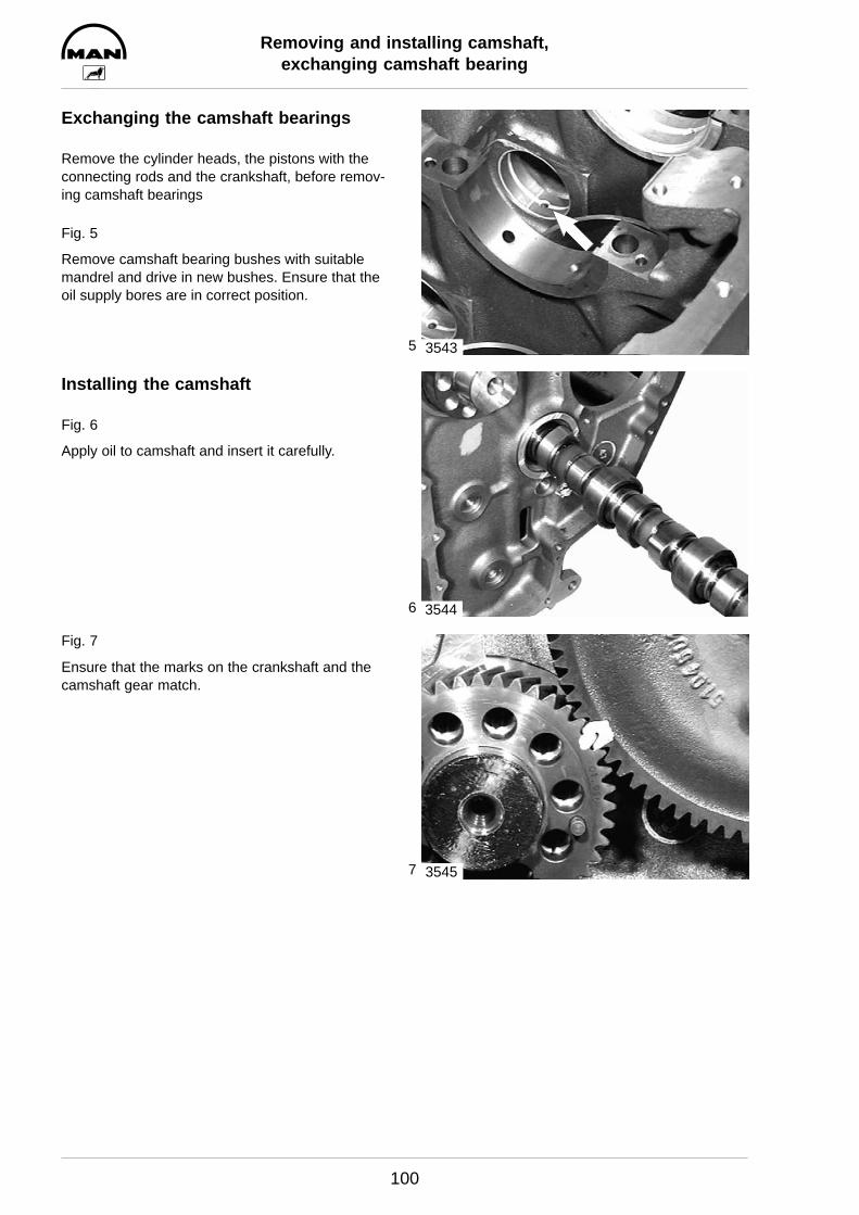
5
6
7
Removing and installing camshaft,exchanging camshaft bearing
100
Exchanging the camshaft bearings
Remove the cylinder heads, the pistons with theconnecting rods and the crankshaft, before remov-ing camshaft bearings
Fig. 5
Remove camshaft bearing bushes with suitablemandrel and drive in new bushes. Ensure that theoil supply bores are in correct position.
Installing the camshaft
Fig. 6
Apply oil to camshaft and insert it carefully.
Fig. 7
Ensure that the marks on the crankshaft and thecamshaft gear match.
3543
3544
3545
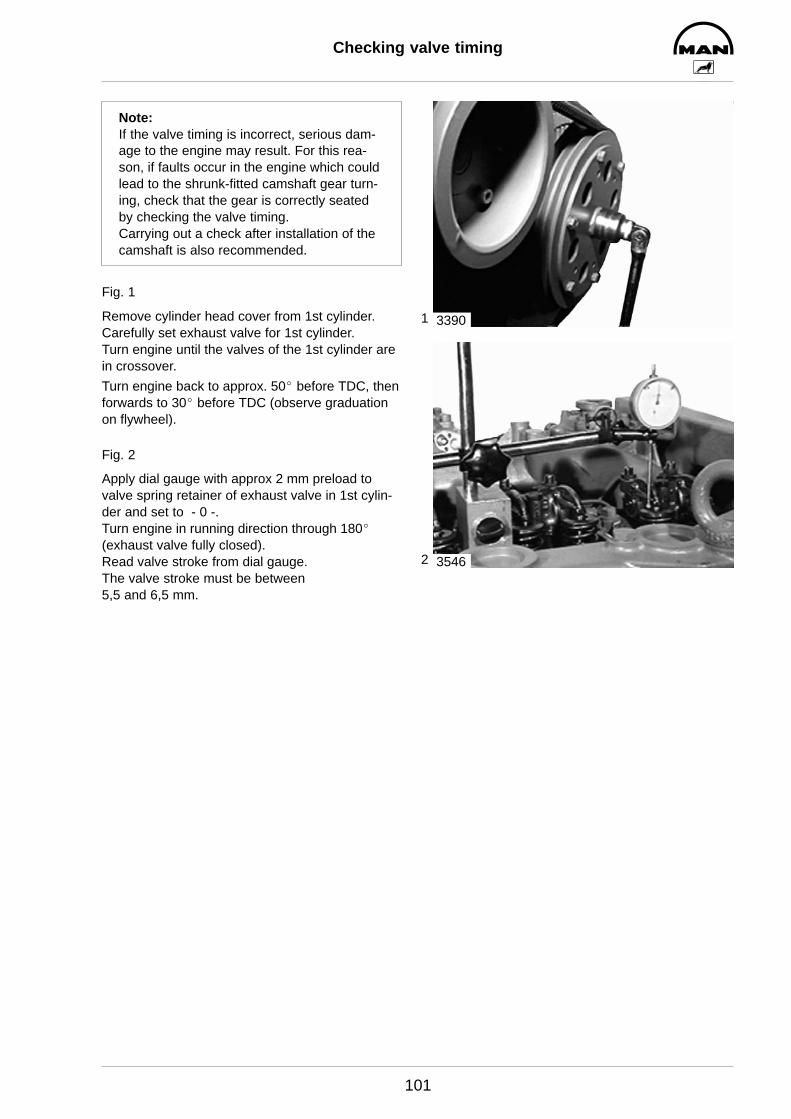
1
2
Checking valve timing
101
Note:If the valve timing is incorrect, serious dam-age to the engine may result. For this rea-son, if faults occur in the engine which couldlead to the shrunk-fitted camshaft gear turn-ing, check that the gear is correctly seatedby checking the valve timing.Carrying out a check after installation of thecamshaft is also recommended.
Fig. 1
Remove cylinder head cover from 1st cylinder.Carefully set exhaust valve for 1st cylinder.Turn engine until the valves of the 1st cylinder arein crossover.
Turn engine back to approx. 50_ before TDC, thenforwards to 30_ before TDC (observe graduationon flywheel).
Fig. 2
Apply dial gauge with approx 2 mm preload tovalve spring retainer of exhaust valve in 1st cylin-der and set to - 0 -.Turn engine in running direction through 180_ (exhaust valve fully closed).Read valve stroke from dial gauge.The valve stroke must be between 5,5 and 6,5 mm.
3390
3546
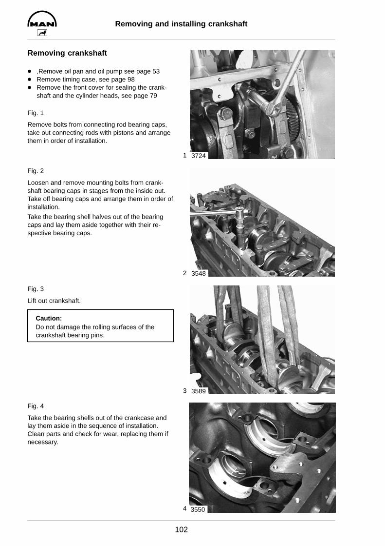
1
2
3
4
Removing and installing crankshaft
102
Removing crankshaft
D ,Remove oil pan and oil pump see page 53D Remove timing case, see page 98D Remove the front cover for sealing the crank-
shaft and the cylinder heads, see page 79
Fig. 1
Remove bolts from connecting rod bearing caps,take out connecting rods with pistons and arrangethem in order of installation.
Fig. 2
Loosen and remove mounting bolts from crank-shaft bearing caps in stages from the inside out.Take off bearing caps and arrange them in order ofinstallation.
Take the bearing shell halves out of the bearingcaps and lay them aside together with their re-spective bearing caps.
Fig. 3
Lift out crankshaft.
Caution:Do not damage the rolling surfaces of thecrankshaft bearing pins.
Fig. 4
Take the bearing shells out of the crankcase andlay them aside in the sequence of installation.Clean parts and check for wear, replacing them ifnecessary.
3724
3548
3589
3550

5
6
7
8
Removing and installing crankshaft
103
Checking spread of bearing shells
Fig. 5
Position bearing shells together on flat surface.Measure and note down spread dimensions ”A”and ”B”.
Spread dimension = A – B
Installing crankshaft
Fig. 6
Clean oil ducts in crankcase and in crankshaft withdry compressed air.
Thoroughly clean bearing shells and bearing journals.
Install bearing shells in crankcase, observing thenumbering.
Fig. 7
Apply oil to the running surfaces on the bearingshells and install crankcase, ensuring that the markings on the crankshaft and camshaft gearscoincide.
Fig. 8
Check whether the bearing cap bolts have ex-ceeded the max. permissible length (see ”Engi-neering, data and setting values”). Bolts that havebeen removed may be reused if the max. permissi-ble length is not exceeded.
Insert bearing cap screws and tighten to specifiedtorque in stages from the inside out (see ”Engi-neering, Data, Setting values”).
Tighten finally by angle.
Check to see that crankshaft runs smoothly.
Important:Faulty bearing caps cannot be replaced singly.
2376
A
B
3543
3545
3551
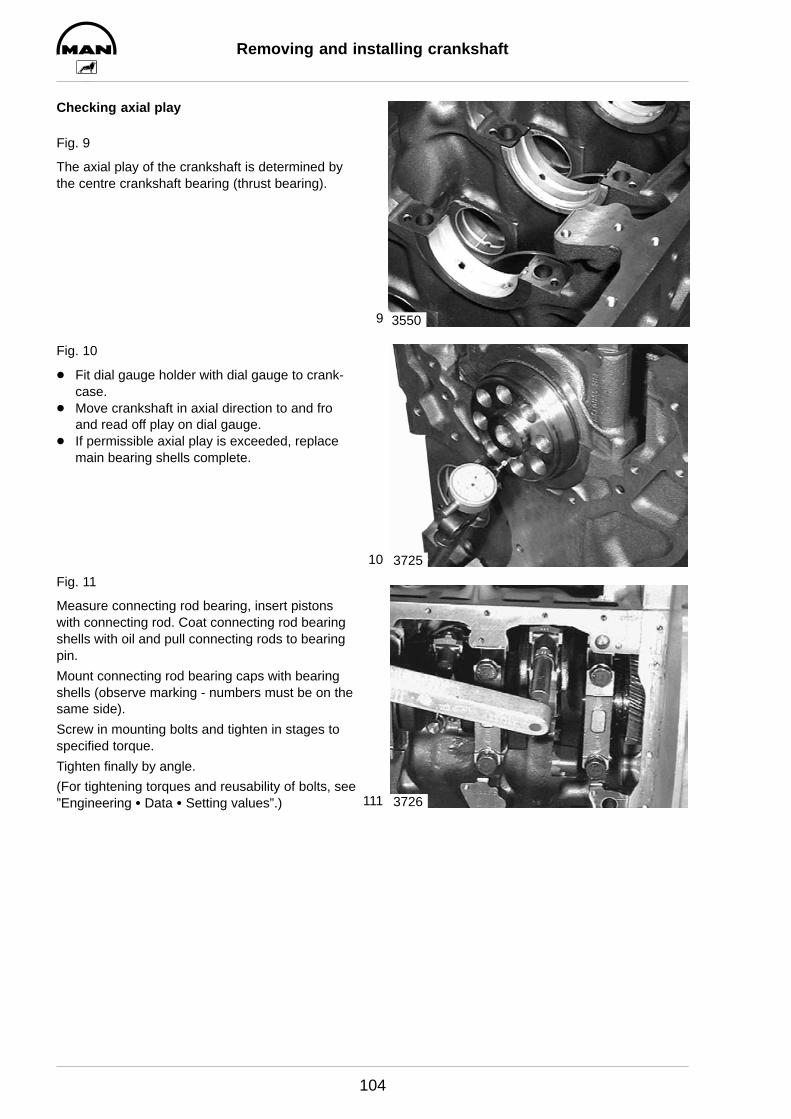
9
10
111
Removing and installing crankshaft
104
Checking axial play
Fig. 9
The axial play of the crankshaft is determined bythe centre crankshaft bearing (thrust bearing).
Fig. 10
D Fit dial gauge holder with dial gauge to crank-case.
D Move crankshaft in axial direction to and froand read off play on dial gauge.
D If permissible axial play is exceeded, replacemain bearing shells complete.
Fig. 11
Measure connecting rod bearing, insert pistonswith connecting rod. Coat connecting rod bearingshells with oil and pull connecting rods to bearingpin.
Mount connecting rod bearing caps with bearingshells (observe marking - numbers must be on thesame side).
Screw in mounting bolts and tighten in stages tospecified torque.
Tighten finally by angle.
(For tightening torques and reusability of bolts, see”Engineering S Data S Setting values”.)
3550
3725
3726

1
2
3
4
Removing and installing piston with connecting rod
105
Removing piston with connecting rod
D Remove oil pan, oil suction pipe, see page 53D Remove cylinder heads, see page 79
Fig. 1
Remove bolts from connecting rod bearing cap.
Fig. 2
Take off connecting rod bearing caps with bearingshells, expediting the procedure by means of lightstrokes with a synthetic hammer if necessary.
Note:Connecting rod bearing caps are match-marked with the connecting rod big ends;arrange them in corresponding order.
Fig. 3
Remove combustion residues (oil carbon) from topcylinder edge using a piece of hard wood.
Caution:Do not damage cylinder liners.
Push out connecting rod with piston in upwarddirection.
Caution:Do not damage oil spray nozzles.
Fig. 4
Lay pistons with connecting rods and associatedcaps aside; use deposit rack if available.Inspect pistons and piston rings visually.
Note:For reworked crankcase sealing faces repairpistons with undersizes of 0.2, 0.4 and 0.6mm in the compression height are available(see ”Engineering S Data S Setting values”).
3724
3553
3554
3555
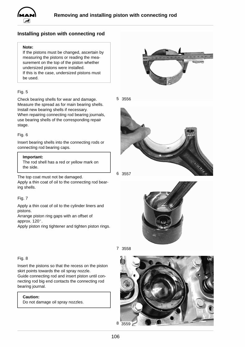
5
6
7
8
Removing and installing piston with connecting rod
106
Installing piston with connecting rod
Note:If the pistons must be changed, ascertain bymeasuring the pistons or reading the mea-surement on the top of the piston whetherundersized pistons were installed.If this is the case, undersized pistons mustbe used.
Fig. 5
Check bearing shells for wear and damage.Measure the spread as for main bearing shells.Install new bearing shells if necessary.When repairing connecting rod bearing journals,use bearing shells of the corresponding repairstage.
Fig. 6
Insert bearing shells into the connecting rods orconnecting rod bearing caps.
Important:The rod shell has a red or yellow mark onthe side.
The top coat must not be damaged.Apply a thin coat of oil to the connecting rod bear-ing shells.
Fig. 7
Apply a thin coat of oil to the cylinder liners andpistons.Arrange piston ring gaps with an offset of approx. 120_.Apply piston ring tightener and tighten piston rings.
Fig. 8
Insert the pistons so that the recess on the pistonskirt points towards the oil spray nozzle.Guide connecting rod and insert piston until con-necting rod big end contacts the connecting rodbearing journal.
Caution:Do not damage oil spray nozzles.
3556
3557
3558
3559

9
10
11
Removing and installing piston with connecting rod
107
Fig. 9
Put connecting rod bearing caps in place.
Important:The numbers on the connecting rod bearingcap and connecting rod big end must be onone side.
Fig. 10
Screw in connecting rod bearing bolts and tightenthem in stages to specified value.
Tighten finally by angle.
(For tightening torques and reusability of bolts, see”Engineering S Data S Setting values”.)
Fig. 11
Slowly turn engine over.Connecting rods and oil spray nozzles (arrow)must not collide or grind against each other.
Note:As far as possible turn engine only in direc-tion of rotation (anti-clockwise as seen whenlooking at the flywheel) in order to preventthe direction of rotation of the raw waterpump impeller being reversed.
3560
3726
3462
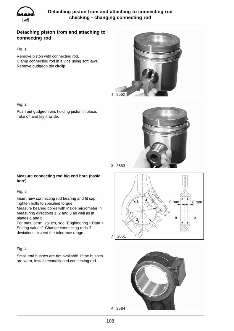
1
2
3
4
Detaching piston from and attaching to connecting rodchecking - changing connecting rod
108
Detaching piston from and attaching toconnecting rod
Fig. 1
Remove piston with connecting rod.Clamp connecting rod in a vice using soft jaws.Remove gudgeon pin circlip.
Fig. 2
Push out gudgeon pin, holding piston in place.Take off and lay it aside.
Measure connecting rod big end bore (basicbore)
Fig. 3
Insert new connecting rod bearing and fit cap.Tighten bolts to specified torque.Measure bearing bores with inside micrometer inmeasuring directions 1, 2 and 3 as well as inplanes a and b.For max. perm. values, see ”Engineering S Data SSetting values”. Change connecting rods if deviations exceed the tolerance range.
Fig. 4
Small end bushes are not available. If the bushesare worn, install reconditioned connecting rod.
3562
3563
3
1 8 mm 8 mm
2ba
2861
3564

5
6
7
Removing piston from and attaching to connecting rodchecking - changing connecting rod
109
Fig. 5
Clean connecting rod and inspect for externaldamage; scrap any defective rods.Check connecting rod to see whether the pistonpin bore is parallel or twisted relative to the bearingshell bore. Change connecting rod if deviationsexceed the tolerance range.
Fig. 6
Fit piston to connecting rod.
Caution:The recess for the oil spray nozzle in the pis-ton shaft (arrow) must be at the side of thesmall end.
Insert gudgeon pin. Fit circlips.Install piston, see page 106.
A
Ø 0
,02
A
3847
3565
4083
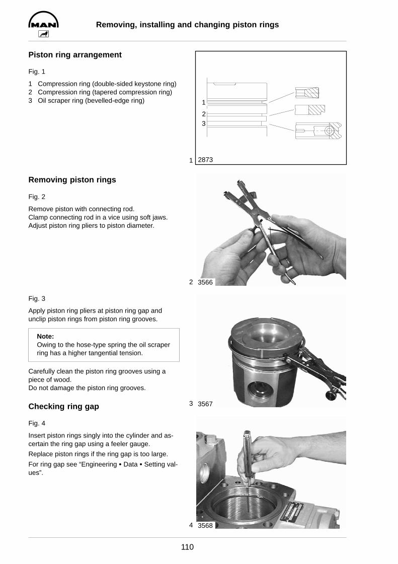
1
2
3
4
Removing, installing and changing piston rings
110
Piston ring arrangement
Fig. 1
1 Compression ring (double-sided keystone ring)2 Compression ring (tapered compression ring)3 Oil scraper ring (bevelled-edge ring)
Removing piston rings
Fig. 2
Remove piston with connecting rod.Clamp connecting rod in a vice using soft jaws.Adjust piston ring pliers to piston diameter.
Fig. 3
Apply piston ring pliers at piston ring gap and unclip piston rings from piston ring grooves.
Note:Owing to the hose-type spring the oil scraperring has a higher tangential tension.
Carefully clean the piston ring grooves using apiece of wood.Do not damage the piston ring grooves.
Checking ring gap
Fig. 4
Insert piston rings singly into the cylinder and as-certain the ring gap using a feeler gauge.
Replace piston rings if the ring gap is too large.
For ring gap see “Engineering S Data S Setting val-ues”.
23
1
2873
3566
3567
3568
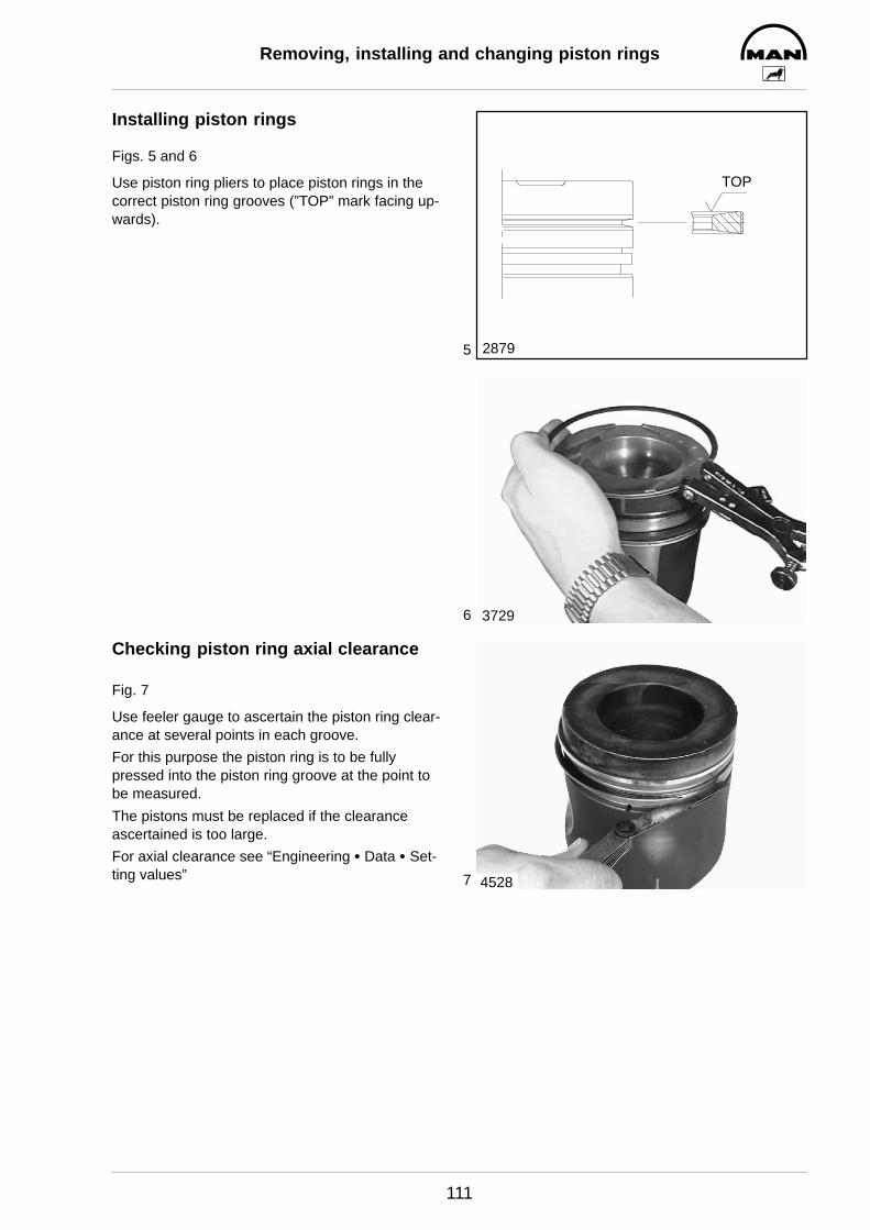
5
6
7
Removing, installing and changing piston rings
111
Installing piston rings
Figs. 5 and 6
Use piston ring pliers to place piston rings in thecorrect piston ring grooves (”TOP” mark facing up-wards).
Checking piston ring axial clearance
Fig. 7
Use feeler gauge to ascertain the piston ring clear-ance at several points in each groove.
For this purpose the piston ring is to be fully pressed into the piston ring groove at the point tobe measured.
The pistons must be replaced if the clearance ascertained is too large.
For axial clearance see “Engineering S Data S Set-ting values”
TOP
2879
3729
4528
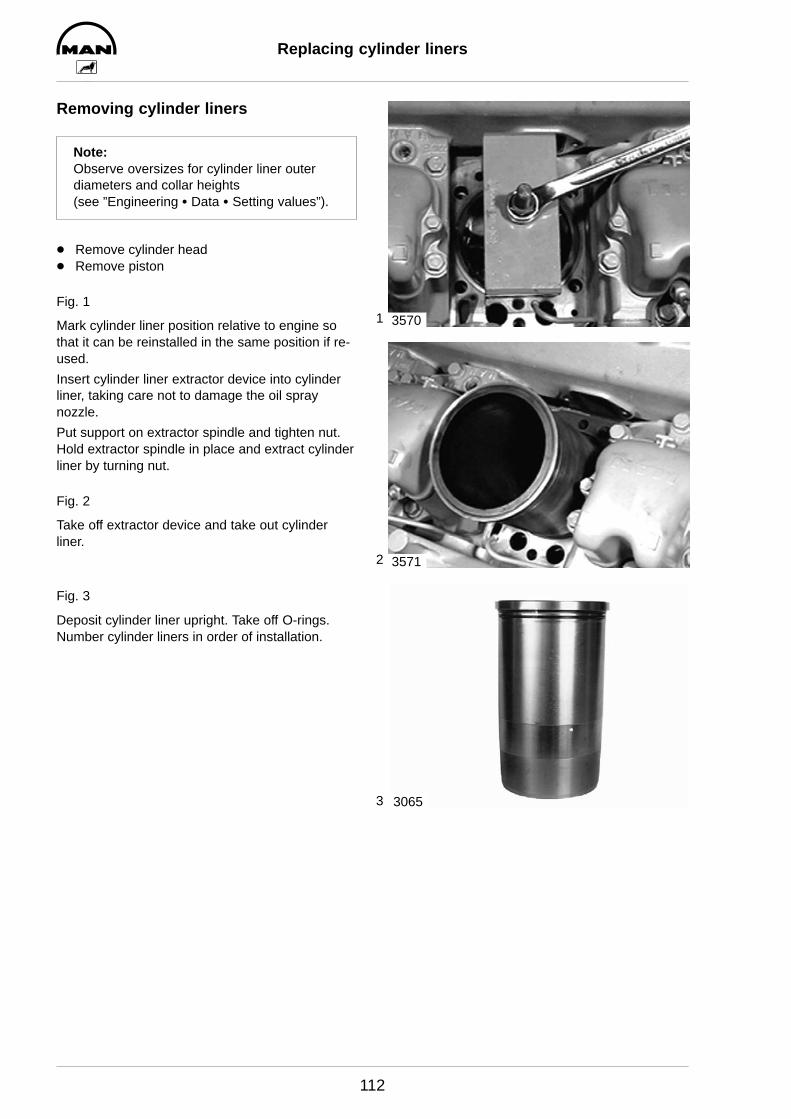
1
2
3
Replacing cylinder liners
112
Removing cylinder liners
Note:Observe oversizes for cylinder liner outerdiameters and collar heights (see ”Engineering S Data S Setting values”).
D Remove cylinder headD Remove piston
Fig. 1
Mark cylinder liner position relative to engine sothat it can be reinstalled in the same position if re-used.
Insert cylinder liner extractor device into cylinderliner, taking care not to damage the oil spraynozzle.
Put support on extractor spindle and tighten nut.Hold extractor spindle in place and extract cylinderliner by turning nut.
Fig. 2
Take off extractor device and take out cylinderliner.
Fig. 3
Deposit cylinder liner upright. Take off O-rings.Number cylinder liners in order of installation.
3570
3571
3065

4
5
Replacing cylinder liners
113
Checking cylinder liner protrusion
Fig. 4
Clean basic bore and cylinder liner.Insert cylinder liner without O-rings into crankcase,observing the marking (ensure that it is identicalwith the position prior to removal).Measure cylinder liner protrusion at at least fourdifferent points, using gauge holder and gauge.
Note:If available, use measuring plate for themeasurement (special tool, see page 132)
Proceed as follows:
Position press-on measuring plate (1) withturned collar facing the liner using 2 fittingsleeves to centre plate.Tighten 4 bolts (2) (improvised: collar bolt51.90020-0270, length shortened to 90 mm)on the press-on measuring plate in stagesand crosswise to 40 Nm.Set dial gauge combination above press-onplate to - 0 - under preload relative to thecrankcase.Measure cylinder liner protrusion at least atfour points.
Fig. 5
Install shim if the protrusion is below the minimumprotrusion even at only one point.The shim is placed under the cylinder liner collar.However, it may be used only if after installationthe upper tolerance limit is not exceeded.
3573
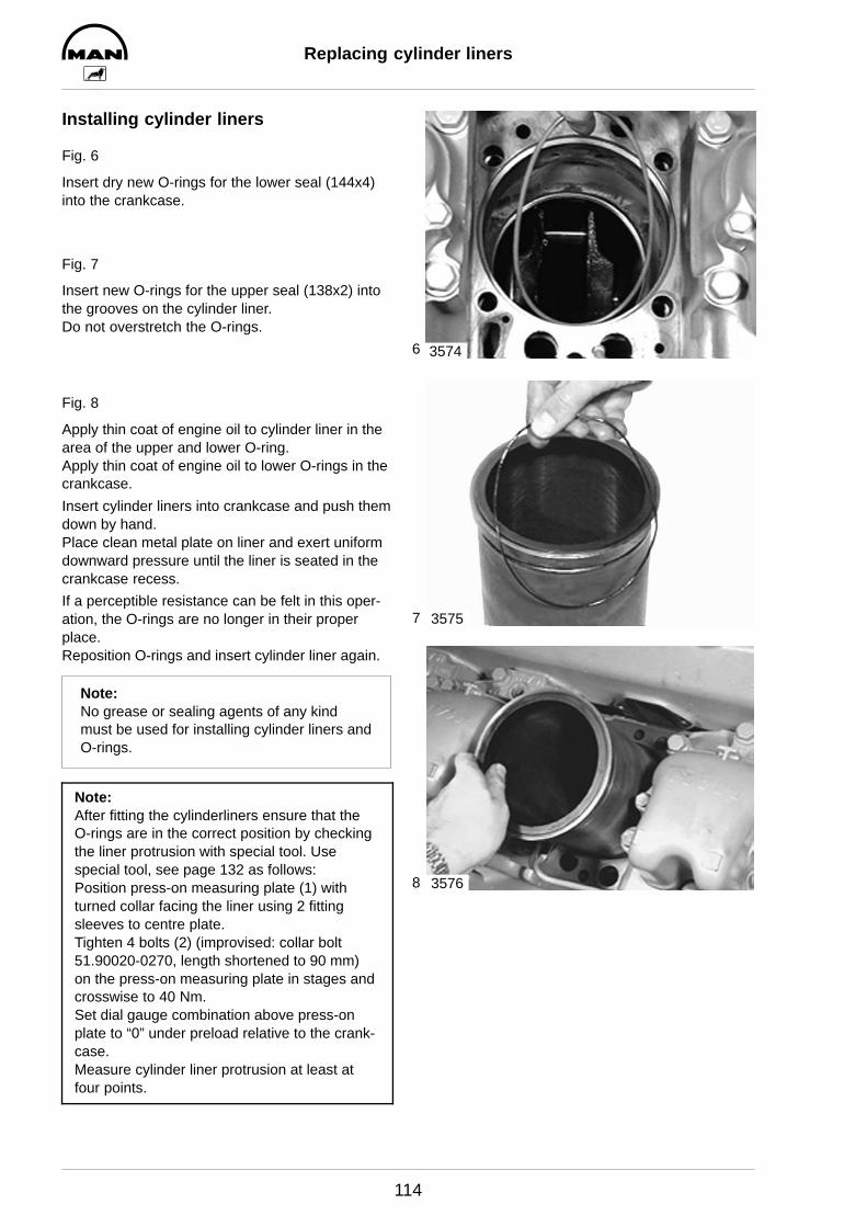
6
7
8
Replacing cylinder liners
114
Installing cylinder liners
Fig. 6
Insert dry new O-rings for the lower seal (144x4)into the crankcase.
Fig. 7
Insert new O-rings for the upper seal (138x2) intothe grooves on the cylinder liner.Do not overstretch the O-rings.
Fig. 8
Apply thin coat of engine oil to cylinder liner in thearea of the upper and lower O-ring.Apply thin coat of engine oil to lower O-rings in thecrankcase.
Insert cylinder liners into crankcase and push themdown by hand.Place clean metal plate on liner and exert uniformdownward pressure until the liner is seated in thecrankcase recess.
If a perceptible resistance can be felt in this oper-ation, the O-rings are no longer in their properplace.Reposition O-rings and insert cylinder liner again.
Note:No grease or sealing agents of any kindmust be used for installing cylinder liners andO-rings.
Note:After fitting the cylinderliners ensure that theO-rings are in the correct position by checkingthe liner protrusion with special tool. Usespecial tool, see page 132 as follows:Position press-on measuring plate (1) withturned collar facing the liner using 2 fittingsleeves to centre plate.Tighten 4 bolts (2) (improvised: collar bolt51.90020-0270, length shortened to 90 mm)on the press-on measuring plate in stages andcrosswise to 40 Nm.Set dial gauge combination above press-onplate to “0” under preload relative to the crank-case.Measure cylinder liner protrusion at least atfour points.
3574
3575
3576
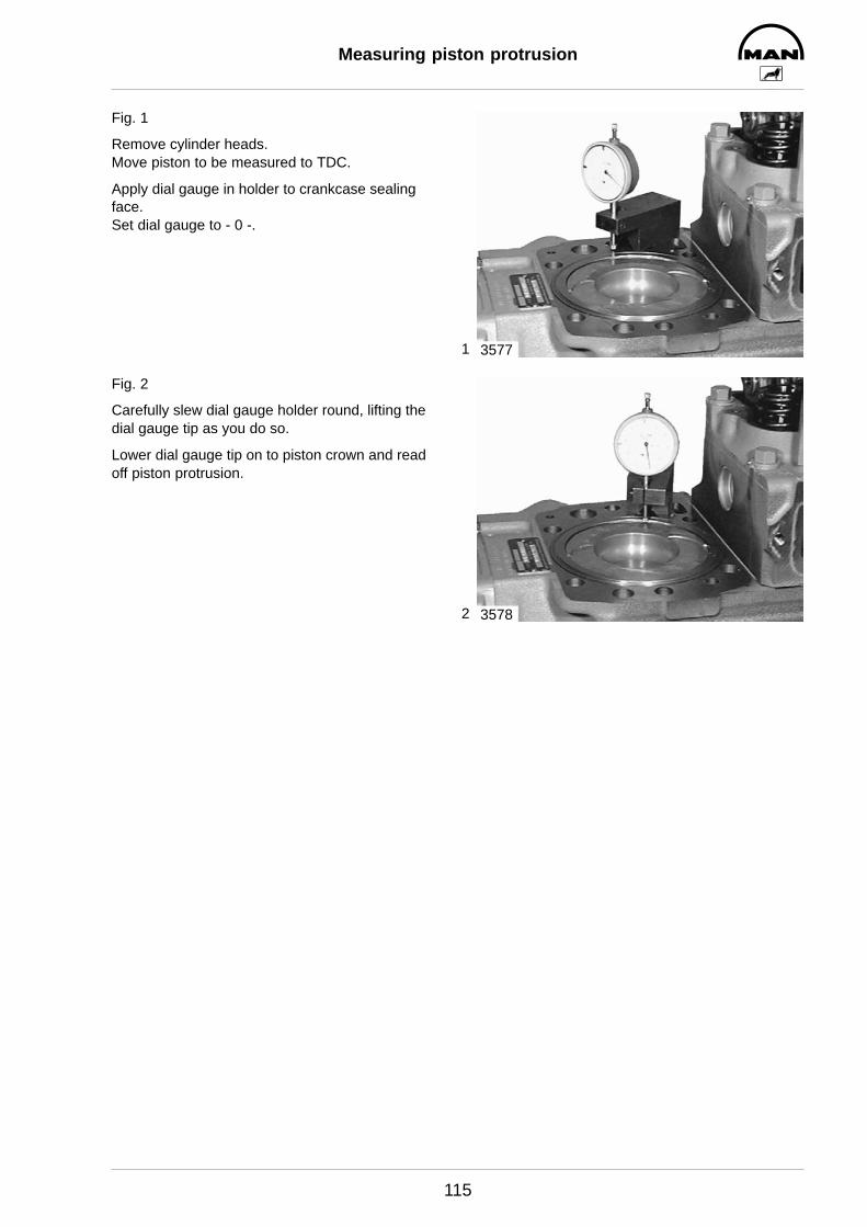
1
2
Measuring piston protrusion
115
Fig. 1
Remove cylinder heads.Move piston to be measured to TDC.
Apply dial gauge in holder to crankcase sealingface.Set dial gauge to - 0 -.
Fig. 2
Carefully slew dial gauge holder round, lifting thedial gauge tip as you do so.
Lower dial gauge tip on to piston crown and readoff piston protrusion.
3577
3578
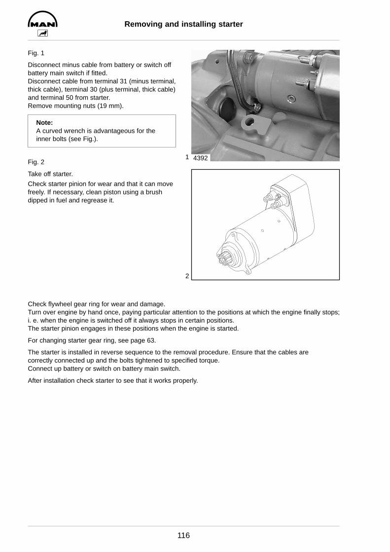
1
2
Removing and installing starter
116
Fig. 1
Disconnect minus cable from battery or switch offbattery main switch if fitted.Disconnect cable from terminal 31 (minus terminal,thick cable), terminal 30 (plus terminal, thick cable)and terminal 50 from starter.Remove mounting nuts (19 mm).
Note:A curved wrench is advantageous for theinner bolts (see Fig.).
Fig. 2
Take off starter.
Check starter pinion for wear and that it can movefreely. If necessary, clean piston using a brushdipped in fuel and regrease it.
4392
Check flywheel gear ring for wear and damage.Turn over engine by hand once, paying particular attention to the positions at which the engine finally stops;i. e. when the engine is switched off it always stops in certain positions.The starter pinion engages in these positions when the engine is started.
For changing starter gear ring, see page 63.
The starter is installed in reverse sequence to the removal procedure. Ensure that the cables are correctly connected up and the bolts tightened to specified torque.Connect up battery or switch on battery main switch.
After installation check starter to see that it works properly.

1
2
3
4
V-belts
117
Checking condition
Fig. 1
D Check V-belts for cracks, oiling, overheatingand wear.
D Change damaged V-belts.
Checking tension
Figs. 2 and 3
Use belt tension indicator to check V-belt tension.
D Lower the gauge arm À in the scale.D Position the tension indicator in the centre of
the belt between the two pulleys so that theedge of the stop face Á locates against the sideof the belt.
D Slowly depress the pressure pad  verticallydownwards until the spring disengages with anaudible click; the gauge arm moves upwards.
A false reading will be obtained if you continue toapply pressure after the spring has disengaged.
Fig. 4
Taking tension reading
D The tension is shown where the top of thegauge arm (1 in picture 2) intersects the kgscale.
D Ensure that the gauge arm does not move be-fore you take the reading.
If the reading does not correspond with the speci-fied value, the V-belt tension must be corrected.
2642
1
2905
2
3
2906
Tensioning forces as per kg scale onthe indicator
V-beltfor newly fitted
assemblyfor mainte-nance af-
width
after as-sembly
after arunningtime of 10 min.
nance after prolon-
ged pe-riods of
operation
B 12,5 50-55 45-50 35
C 13 50-55 40-45 35
2/3VX 90-100 70-80 60
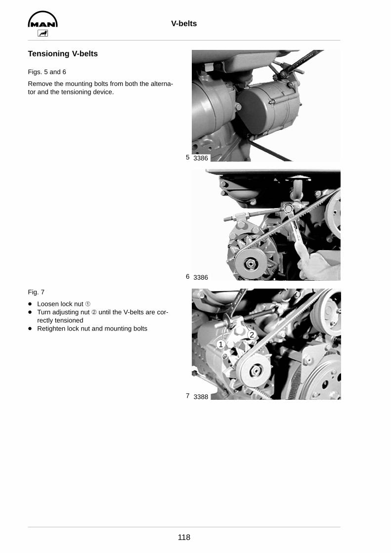
5
6
7
V-belts
118
Tensioning V-belts
Figs. 5 and 6
Remove the mounting bolts from both the alterna-tor and the tensioning device.
Fig. 7
D Loosen lock nut ÀD Turn adjusting nut Á until the V-belts are cor-
rectly tensionedD Retighten lock nut and mounting bolts
3386
3386
3388
12

Coolant level probe
119
Monitoring the coolant level
All engines are equipped with either one or two coolant level probes for monitoring the coolant level in thecoolant expansion tank. This probe is of the capacitative type. The sensor and the evaluating electronicsform a unit.
If the coolant falls below the level monitored a minus potential is sent to the signal output ”S”. With this acheck lamp or a relay can be triggered.
Checking the coolant level probe
The probe features an integrated checking function. As soon as voltage is applied to the probe the signalappears for approx. 2 seconds to signalise that the probe is ready for operation.
If this signal does not appear, the probe must be checked.
It is not possible to carry out a functional check by measuring the resistance (ohmmeter) because of theinternal transistors.
The check can be carried out with a water tank and a small test bulb (< 3 watt).
Dip the probe into the water and apply a supply voltage of 24 V to the plus and minus leads. The output ”S”is to be connected to the plus lead via the test lamp. The test lamp does not come on.
If the probe is taken out of the water, the test lamp must come on after approx. 7 seconds.
If the lamp does not come on the probe is defective and must be changed.
24V+
–
S
max. 3 W
+
–
S
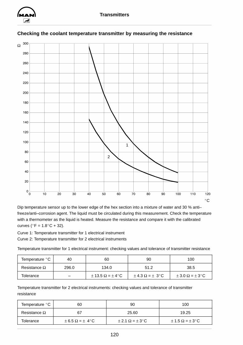
Transmitters
120
Checking the coolant temperature transmitter by measuring the resistance
0
20
40
60
80
100
120
140
160
180
200
220
240
260
280
300
0 10 20 30 40 50 60 70 80 90 100 110 120
_C
Ω
1
2
Dip temperature sensor up to the lower edge of the hex section into a mixture of water and 30 % anti–
freeze/anti–corrosion agent. The liquid must be circulated during this measurement. Check the temperature
with a thermometer as the liquid is heated. Measure the resistance and compare it with the calibrated
curves (_F = 1.8_C + 32).
Curve 1: Temperature transmitter for 1 electrical instrument
Curve 2: Temperature transmitter for 2 electrical instruments
Temperature transmitter for 1 electrical instrument: checking values and tolerance of transmitter resistance
Temperature _C 40 60 90 100
Resistance Ω 296.0 134.0 51.2 38.5
Tolerance – ± 13.5 Ω = ± 4_C ± 4.3 Ω = ± 3_C ± 3.0 Ω = ± 3_C
Temperature transmitter for 2 electrical instruments: checking values and tolerance of transmitter
resistance
Temperature _C 60 90 100
Resistance Ω 67 25.60 19.25
Tolerance ± 6.5 Ω = ± 4_C ± 2.1 Ω = ± 3_C ± 1.5 Ω = ± 3_C
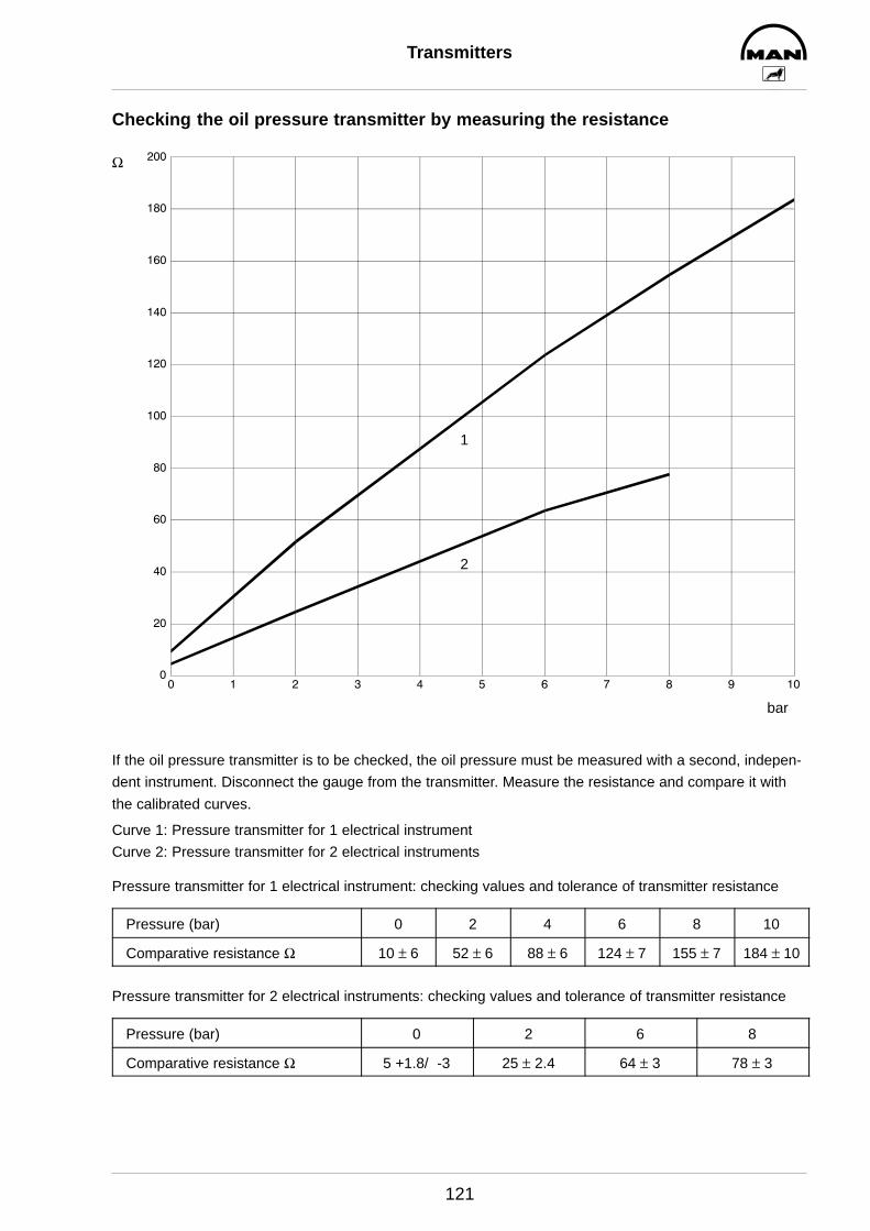
Transmitters
121
Checking the oil pressure transmitter by measuring the resistance
0
20
40
60
80
100
120
140
160
180
200
0 1 2 3 4 5 6 7 8 9 10
bar
Ω
1
2
If the oil pressure transmitter is to be checked, the oil pressure must be measured with a second, indepen-
dent instrument. Disconnect the gauge from the transmitter. Measure the resistance and compare it with
the calibrated curves.
Curve 1: Pressure transmitter for 1 electrical instrument
Curve 2: Pressure transmitter for 2 electrical instruments
Pressure transmitter for 1 electrical instrument: checking values and tolerance of transmitter resistance
Pressure (bar) 0 2 4 6 8 10
Comparative resistance Ω 10 ± 6 52 ± 6 88 ± 6 124 ± 7 155 ± 7 184 ± 10
Pressure transmitter for 2 electrical instruments: checking values and tolerance of transmitter resistance
Pressure (bar) 0 2 6 8
Comparative resistance Ω 5 +1.8/ -3 25 ± 2.4 64 ± 3 78 ± 3
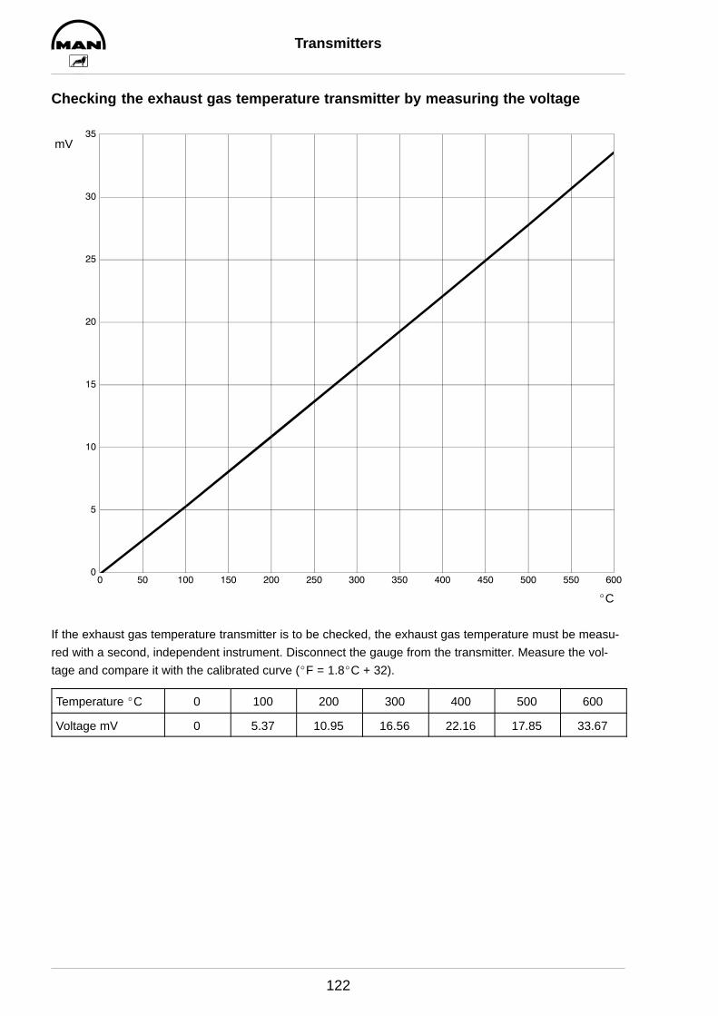
Transmitters
122
Checking the exhaust gas temperature transmitter by measuring the voltage
0
5
10
15
20
25
30
35
0 50 100 150 200 250 300 350 400 450 500 550 600
mV
_C
If the exhaust gas temperature transmitter is to be checked, the exhaust gas temperature must be measu-
red with a second, independent instrument. Disconnect the gauge from the transmitter. Measure the vol-
tage and compare it with the calibrated curve (_F = 1.8_C + 32).
Temperature _C 0 100 200 300 400 500 600
Voltage mV 0 5.37 10.95 16.56 22.16 17.85 33.67
123
Special tools

Special tools
124
2
3
4
5
6
7 9
1
8
6.1 6.2 6.3
Special tools
125
Fig. no. Designation Item number
1 Test connection for compression recorder 80.99607–0002
2 V-belt tension indicator 81.66814–6001
3 Valve gauge 80.99607–0076
4 Valve setting spanner 83.09195–0002
5 Spanner for nuts on injection lines (17 mm) 80.99603–0025
6 Socket spanner set for fuel injector
6.2 4-groove 80.99603–0049
6.3 4-groove with fixing screw 80.99603–0121
6.4 open, 3-groove 80.99603–0038
7 Inertia puller for fuel injectior 80.99602–0011
8 Special wrench for cylinder head bolt under fuel injector 80.99603–0095
9 Clamping device for fuel injectors 80.99606–0008
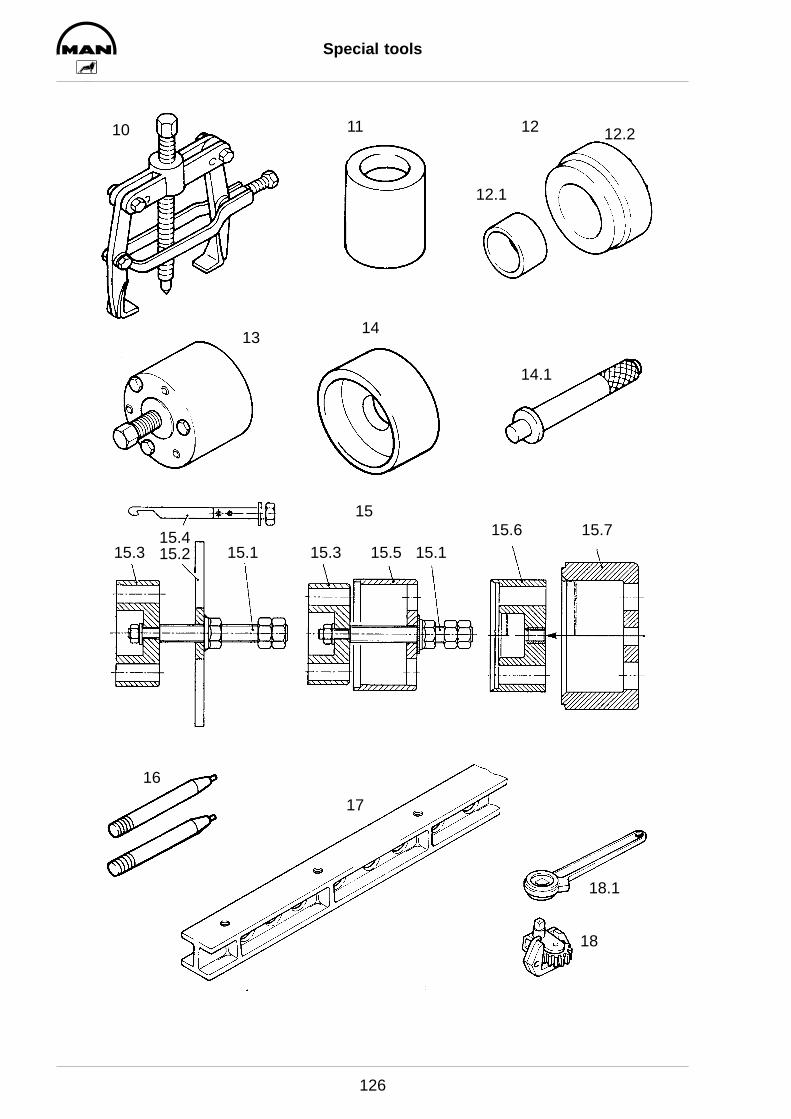
Special tools
126
10 11
16
14
14.1
12
13
18
18.1
17
12.1
12.2
15.515.4
15.115.115.215.3 15.315.6 15.7
15
Special tools
127
Fig. no. Designation Item number
10 Puller for water pump pulley 80.99601–0037
11 Pressing mandrel for cassette seal in conjunction with handle 14.1 80.99617–0091
12 Driving mandrel for seal in timing case
consisting of:
12.1 Guide sleeve 80.99604–0068
12.2 Pressing plate in conjunction with handle 14.1 80.99604–0069
13 Puller for front crankshaft bearing race 80.99601–0076
14 Pressing tool for bearing race on flywheel in conjunction with handle 14.1 80.99617–0017
14.1 Handle 80.99617–0129
15 Special tools for front crankshaft seal 80.99606–6011
Components:
15.1 Spindle 80.99606–0229
15.2 Extractor device 80.99606–0298
15.3 Adapter 80.99606–0264
15.4 Extractor hook 80.99606–6013
15.5 Pressing sleeve 80.99606–0300
15.6 Adapter 80.99606–0302
15.7 Fitting sleeve 80.99606–0301
16 Guide mandrels for flywheel 80.99617–0020
17 Steel ruler 80.99607–0044
18 Engine turning device 80.99626–0004
18.1 Standard ratchet for 18 80.99627–0001

Special tools
128
2122
23
25
25.2
24
25.1
26
27.1 27.2
27
20.119.219.1 20.2
19 20

Special tools
129
Fig. no. Designation Item number
19 Sleeves for valve stem seal
19.1 Insert sleeve for valve stem seal 80.99616–0004
19.2 Pressing sleeve for valve stem seal 80.99604–0005
20 Pressing tool for valve guide
20.1 Pressing mandrel for valve guide 80.99617–0013
20.2 Pressing rings in conjunction with 20.1 80.99616–0003
21 Piston ring tightener 80.99613–0035
22 Piston ring tightening sleeve 80.99604–0134
23 Tightening angle gauge 80.99605–0010
24 Piston ring pliers 83.09144–6090
25 Cylinder liner extractor device 80.99602–0019
25.1 Support for 25 80.99623–0003
25.2 Extractor plate 83.09143–0195
26 Cooling system test unit 80.99607–0061
27 Thread-cutting tool
27.1 Thread drill set, M15 x 2, for cylinder head bolt threads 80.40001–0001
27.2 Associated die ring 80.43001–0001
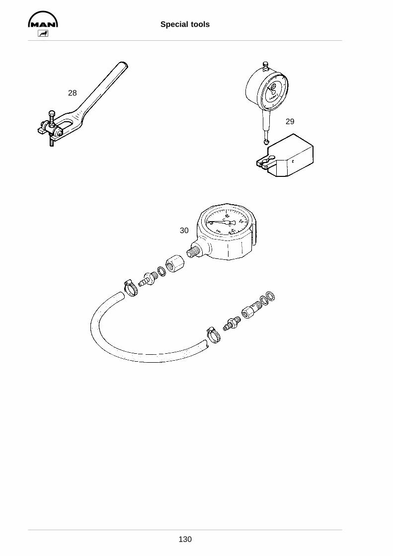
Special tools
130
29
28
30
Special tools
131
Fig. no. Designation Item number
28 Valve assembly lever 80.99606–0031
29 Dial gauge holder for measuring valve retrusion and piston protrusion 90.99605–0172
30 Pressure gauge + accessories for charge-air pressure measurement 80.99605–0160
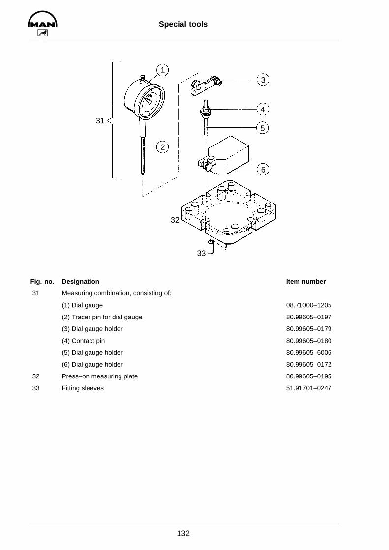
Special tools
132
31
1
2
3
4
5
6
32
33
Fig. no. Designation Item number
31 Measuring combination, consisting of:
(1) Dial gauge 08.71000–1205
(2) Tracer pin for dial gauge 80.99605–0197
(3) Dial gauge holder 80.99605–0179
(4) Contact pin 80.99605–0180
(5) Dial gauge holder 80.99605–6006
(6) Dial gauge holder 80.99605–0172
32 Press–on measuring plate 80.99605–0195
33 Fitting sleeves 51.91701–0247
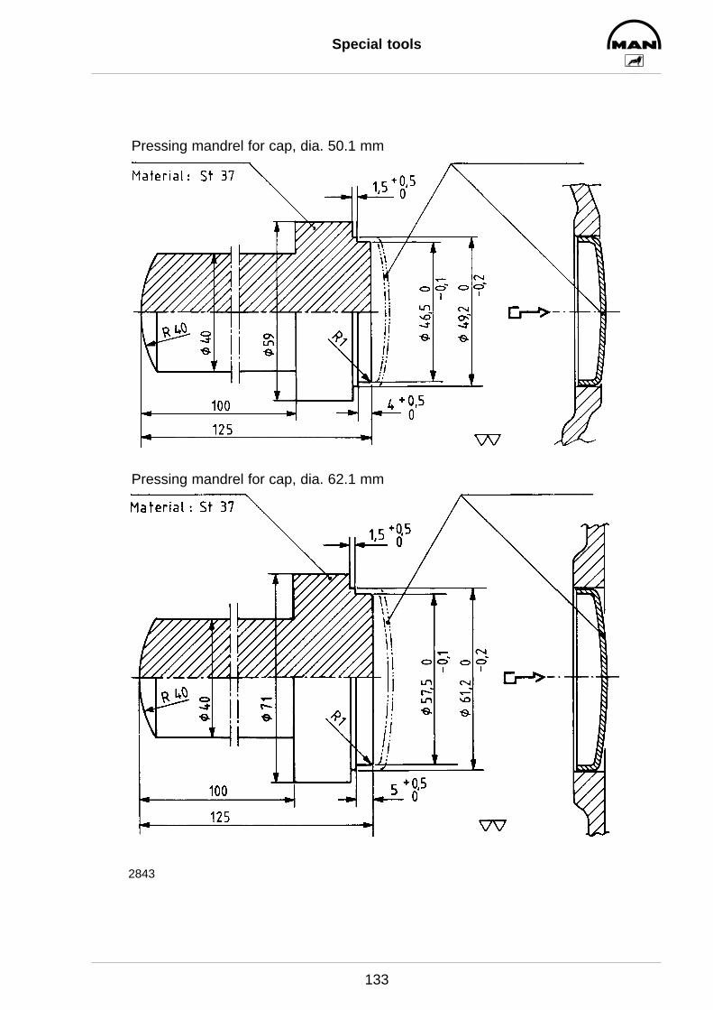
Special tools
133
2843
Pressing mandrel for cap, dia. 50.1 mm
Pressing mandrel for cap, dia. 62.1 mm
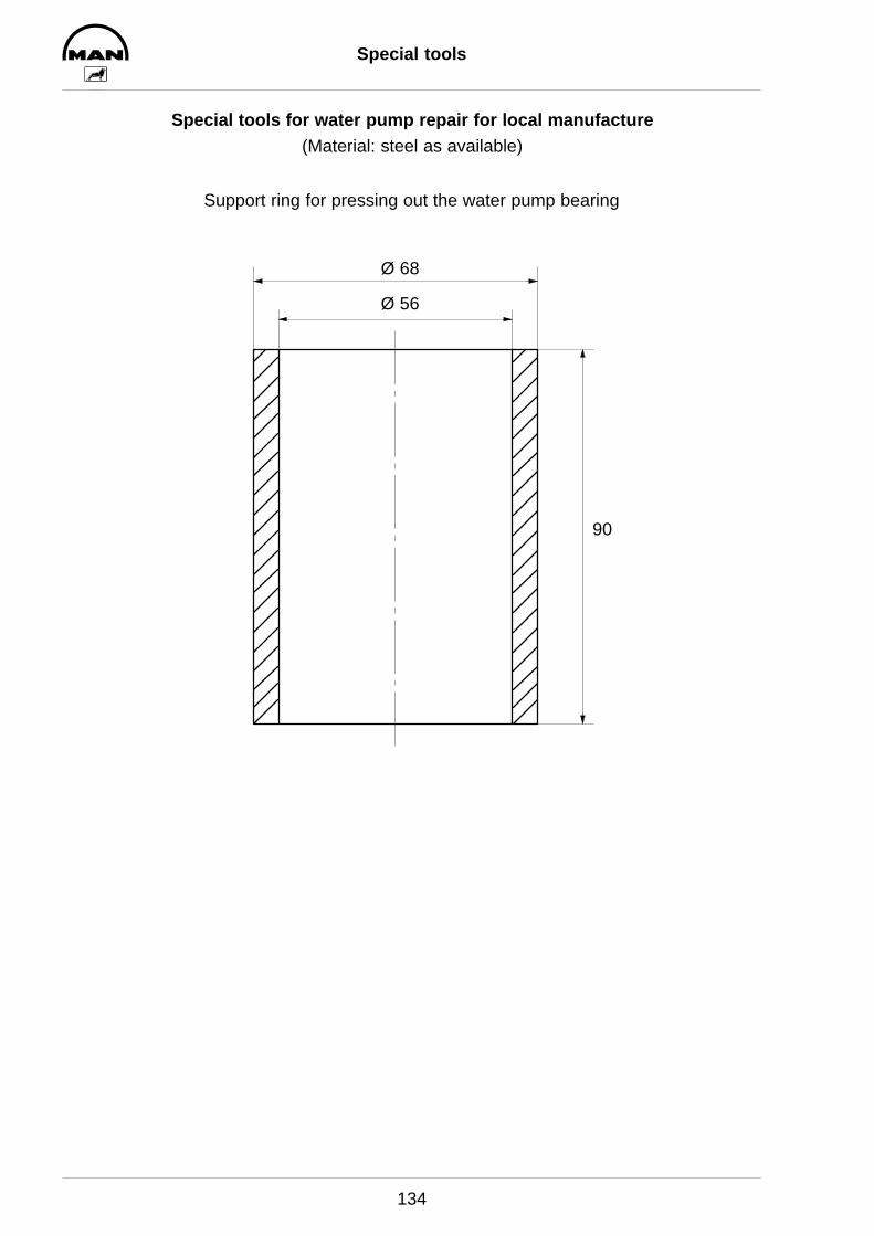
Special tools
134
Special tools for water pump repair for local manufacture(Material: steel as available)
Support ring for pressing out the water pump bearing
Ø 68
Ø 56
90
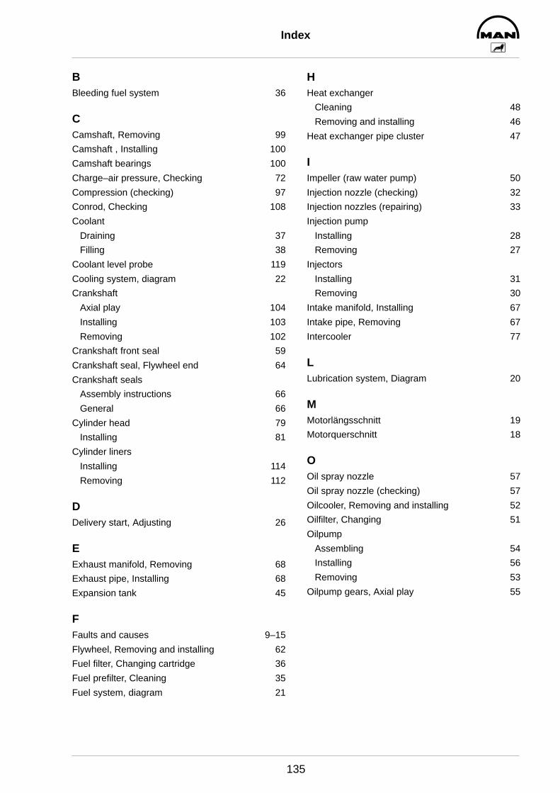
Index
135
BBleeding fuel system 36
CCamshaft, Removing 99
Camshaft , Installing 100
Camshaft bearings 100
Charge–air pressure, Checking 72
Compression (checking) 97
Conrod, Checking 108
Coolant
Draining 37
Filling 38
Coolant level probe 119
Cooling system, diagram 22
Crankshaft
Axial play 104
Installing 103
Removing 102
Crankshaft front seal 59
Crankshaft seal, Flywheel end 64
Crankshaft seals
Assembly instructions 66
General 66
Cylinder head 79
Installing 81
Cylinder liners
Installing 114
Removing 112
DDelivery start, Adjusting 26
EExhaust manifold, Removing 68
Exhaust pipe, Installing 68
Expansion tank 45
FFaults and causes 9–15
Flywheel, Removing and installing 62
Fuel filter, Changing cartridge 36
Fuel prefilter, Cleaning 35
Fuel system, diagram 21
HHeat exchanger
Cleaning 48
Removing and installing 46
Heat exchanger pipe cluster 47
IImpeller (raw water pump) 50
Injection nozzle (checking) 32
Injection nozzles (repairing) 33
Injection pump
Installing 28
Removing 27
Injectors
Installing 31
Removing 30
Intake manifold, Installing 67
Intake pipe, Removing 67
Intercooler 77
LLubrication system, Diagram 20
MMotorlängsschnitt 19
Motorquerschnitt 18
OOil spray nozzle 57
Oil spray nozzle (checking) 57
Oilcooler, Removing and installing 52
Oilfilter, Changing 51
Oilpump
Assembling 54
Installing 56
Removing 53
Oilpump gears, Axial play 55
Index
136
PPiston
Detaching from conrod, Attaching to conrod108
Installing 106
Removing 105
Piston protrusion 115
Piston ring axial play 111
Piston ring gap 110
Piston rings
Installing 111
Removing 110
Preventing environmental damage 6
RRaw water pump 49
Rocker arms 86
SSafety precautions 4–9
Sicherheitsvorschriften, Preventing engine damage6
Start of delivery, Checking 23
Starter, Removing and installing 116
Starter gear ring 63
TTiming case, Removing and installing 98
Transmitter
Coolant temperature 120
Exhaust gas temperature 122
Oil pressure 121
Thermostat, Removing and installing 39
Turbocharger
Axial play 75
Installing 74
Radial play 75
Removing 73
Trouble shooting 70
VV–belts 117–118
Valve guides, Removing and Installing 90
Valve recess 89
Valve seat, Reworking 93
Valve seat insert
Installing 92
Removing 91
Valve timing 101
Valves
Installing 88
Refacing 96
Removing 87
Ventilstößel 99
Vibration damper
Installing 61
removing 58
WWaste gate 76
Waste water conditioning 48
Water pump, Removing and installing 40
Water pump, Repairing 41