Embed Size (px)
Citation preview

Renault DUSTERDriver’s handbook

A passion for performance
ELF, partner of
RENAULT recommends ELFPartners in cutting-edge automotive technology, Elf and Renault combine their expertise on both the racetrack and the city streets. This enduring partnership gives drivers a range of lubricants perfectly suited to Renault cars. Lasting protection and optimum performance for your engine – guaranteed. Whether changing the oil or simply topping up, to find the approved ELF lubricant best suited to your vehicle, ask your Renault dealer for a recommendation or consult your vehi-cle maintenance handbook.
www.lubricants.elf.com
A brand from
0.1
The descriptions of the models given in this handbook are based on the technical specifications at the time of writing. This hand-book covers all items of equipment (both standard and optional) available for these models, but whether or not these are fitted to the vehicle depends on the version, options selected and the country where the vehicle is sold.This handbook may also contain information about items of equipment to be introduced later in the model year.Throughout the manual, the «approved dealer» is your DACIA dealer.
Welcome aboard your vehicle
This Driver’s Handbook contains the information necessary:– for you to familiarise yourself with your vehicle, to use it to its best advantage and to benefit fully from the all the functions and
the technical developments it incorporates.– to ensure that it always gives the best performance by following the simple, but comprehensive advice concerning regular main-
tenance.– to enable you to deal quickly with minor faults not requiring specialist attention.It is well worth taking a few minutes to read this handbook to familiarise yourself with the information and guidelines it contains about the vehicle and its functions and new features. If certain points are still unclear, our Network technicians will be only too pleased to provide you with any additional information.The following symbol will help you when reading this handbook:
Translated from French. Copying or translation, in part or in full, is forbidden unless prior written permission has been obtained from the vehicle manufac-turer.
To indicate a hazard, danger or safety recommendation.
Enjoy driving your new vehicle.

0.2

0.3
Getting to know your vehicle ...............................
Driving ...................................................................
Your comfort .........................................................
Maintenance .........................................................
Practical advice ....................................................
Technical specifications ......................................
Alphabetical index ...............................................
Sections
1
C O N T E N T S
2
3
4
5
6
7

0.4
1.1
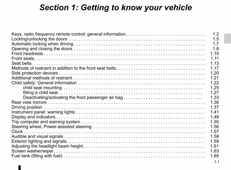
Section 1: Getting to know your vehicle
Keys, radio frequency remote control: general information . . . . . . . . . . . . . . . . . . . . . . . . . . . . . . . . 1.2Locking/unlocking the doors . . . . . . . . . . . . . . . . . . . . . . . . . . . . . . . . . . . . . . . . . . . . . . . . . . . . . . . 1.5Automatic locking when driving . . . . . . . . . . . . . . . . . . . . . . . . . . . . . . . . . . . . . . . . . . . . . . . . . . . . . 1.7Opening and closing the doors . . . . . . . . . . . . . . . . . . . . . . . . . . . . . . . . . . . . . . . . . . . . . . . . . . . . . 1.8Front headrests . . . . . . . . . . . . . . . . . . . . . . . . . . . . . . . . . . . . . . . . . . . . . . . . . . . . . . . . . . . . . . . . . 1.10Front seats. . . . . . . . . . . . . . . . . . . . . . . . . . . . . . . . . . . . . . . . . . . . . . . . . . . . . . . . . . . . . . . . . . . . . 1.11Seat belts. . . . . . . . . . . . . . . . . . . . . . . . . . . . . . . . . . . . . . . . . . . . . . . . . . . . . . . . . . . . . . . . . . . . . . 1.13Methods of restraint in addition to the front seat belts . . . . . . . . . . . . . . . . . . . . . . . . . . . . . . . . . . . . 1.17Side protection devices . . . . . . . . . . . . . . . . . . . . . . . . . . . . . . . . . . . . . . . . . . . . . . . . . . . . . . . . . . . 1.20Additional methods of restraint . . . . . . . . . . . . . . . . . . . . . . . . . . . . . . . . . . . . . . . . . . . . . . . . . . . . . 1.21Child safety: General information . . . . . . . . . . . . . . . . . . . . . . . . . . . . . . . . . . . . . . . . . . . . . . . . . . . 1.22
child seat mounting . . . . . . . . . . . . . . . . . . . . . . . . . . . . . . . . . . . . . . . . . . . . . . . . . . . . . . . . 1.25fitting a child seat . . . . . . . . . . . . . . . . . . . . . . . . . . . . . . . . . . . . . . . . . . . . . . . . . . . . . . . . . . 1.27Deactivating/activating the front passenger air bag . . . . . . . . . . . . . . . . . . . . . . . . . . . . . . . . 1.33
Rear view mirrors . . . . . . . . . . . . . . . . . . . . . . . . . . . . . . . . . . . . . . . . . . . . . . . . . . . . . . . . . . . . . . . 1.36Driving position . . . . . . . . . . . . . . . . . . . . . . . . . . . . . . . . . . . . . . . . . . . . . . . . . . . . . . . . . . . . . . . . . 1.37Instrument panel: warning lights . . . . . . . . . . . . . . . . . . . . . . . . . . . . . . . . . . . . . . . . . . . . . . . . . . . . 1.41Display and indicators . . . . . . . . . . . . . . . . . . . . . . . . . . . . . . . . . . . . . . . . . . . . . . . . . . . . . . . . . . . . 1.48Trip computer and warning system . . . . . . . . . . . . . . . . . . . . . . . . . . . . . . . . . . . . . . . . . . . . . . . . . . 1.50Steering wheel, Power-assisted steering . . . . . . . . . . . . . . . . . . . . . . . . . . . . . . . . . . . . . . . . . . . . . 1.56Clock . . . . . . . . . . . . . . . . . . . . . . . . . . . . . . . . . . . . . . . . . . . . . . . . . . . . . . . . . . . . . . . . . . . . . . . . . 1.57Audible and visual signals . . . . . . . . . . . . . . . . . . . . . . . . . . . . . . . . . . . . . . . . . . . . . . . . . . . . . . . . . 1.58Exterior lighting and signals. . . . . . . . . . . . . . . . . . . . . . . . . . . . . . . . . . . . . . . . . . . . . . . . . . . . . . . . 1.59Adjusting the headlight beam height . . . . . . . . . . . . . . . . . . . . . . . . . . . . . . . . . . . . . . . . . . . . . . . . . 1.61Screen washer/wiper . . . . . . . . . . . . . . . . . . . . . . . . . . . . . . . . . . . . . . . . . . . . . . . . . . . . . . . . . . . . . 1.63Fuel tank (filling with fuel) . . . . . . . . . . . . . . . . . . . . . . . . . . . . . . . . . . . . . . . . . . . . . . . . . . . . . . . . . 1.65

1.2
KEYS, RADIO FREQUENCY REMOTE CONTROL: general information (1/2)
Radio frequency remote control B or C2 Locks all the opening elements.3 Unlocks all the opening elements.
Driver’s responsibility when parking or stopping the vehicleNever leave an animal, child or adult who is not self-sufficient alone on your vehicle, even for a short time.
They may pose a risk to themselves or to others by starting the engine, activating equipment such as the electric windows or by locking the doors.Also, in hot and/or sunny weather, please remember that the temperature inside the passenger compartment increases very quickly.RISK OF DEATH OR SERIOUS INJURY.
Key A1 Coded key for ignition switch, doors
and fuel filler cap.
The key must not be used for any function other than those described in the handbook (removing the cap from a bottle, etc.).
3
2
5
C
4 Coded key for ignition switch, driv-er’s door and fuel filler cap.
5 Remote engine start-up.
41
2
3
4A B

1.3
The remote control unit operating rangeThis varies according to the environ-ment. It is therefore important when handling the remote control to ensure that you do not lock or unlock the ve-hicle by inadvertently pressing the but-tons.
InterferenceThe presence of certain objects (metal objects, mobile telephones, or an area with strong electromagnetic radiation, etc.) close to the key may create inter-ference and affect the operation of the system.
KEYS, RADIO FREQUENCY REMOTE CONTROL: general information (2/2)
Replacement and additional keys or remote controlsIf you lose your remote control key or require another, you can obtain one from an approved dealer.If a remote control or key is re-placed, it will be necessary to take the vehicle and all of its remote control keys to an authorised dealer to reset them.You may use up to four remote con-trol keys per vehicle.
Remote control key failureMake sure that the correct battery type is being used, and that the battery is in good condition and in-serted correctly. These batteries have a service life of approximately two years.Refer to the information on “Radio frequency remote control: Batteries” in Section 5.
AdviceAvoid leaving the remote control in hot, cold or humid areas.

1.4
RADIO FREQUENCY REMOTE CONTROL: useLocking the doorsPress locking button 1.The hazard warning lights and side in-dicator lights flash twice to indicate that the doors have locked.If a door or the tailgate is open or not properly shut, the doors and tailgate lock then quickly unlock and the hazard warning lights and side indicator lights do not flash.
Unlocking the doorsPress unlocking button 2.The hazard warning lights and side in-dicator lights flash once to indicate that the doors have unlocked.
The key must not be used for any function other than those described in the handbook (removing the cap from a bottle, etc.).
Driver’s responsibility when parking or stopping the vehicleNever leave an animal,
child or adult who is not self-suffi-cient alone on your vehicle, even for a short time.They may pose a risk to themselves or to others by starting the engine, activating equipment such as the electric windows or by locking the doors.Also, in hot and/or sunny weather, please remember that the tempera-ture inside the passenger compart-ment increases very quickly.RISK OF DEATH OR SERIOUS INJURY.
If the vehicle has been unlocked but neither the doors or tailgate are open, it locks again automatically after two minutes.
1
2

1.5
LOCKING AND UNLOCKING THE DOORS (1/2)
Manual lockingFrom the outsideUnlock the doors using the remote con-trol (refer to information on the “Radio frequency remote control: use” in Section 1) or using the key in one of the door locks.Depending on the vehicle, the key locks and unlocks the driver’s door or all four doors.From the inside(depending on vehicle)Push in button 1 to lock and lift button 1 to unlock.
Child safetyTo make it impossible for the rear doors to be opened from the inside, move lever 2 on each door and check from the inside that the doors are securely locked.
1 2
Never leave your vehicle with the key or remote con-trol inside.
Driver’s responsibilityIf you decide to keep the doors locked when you are driving, remember that it
may be more difficult for those as-sisting you to gain access to the passenger compartment in the event of an emergency.

1.6
LOCKING AND UNLOCKING THE DOORS (2/2)
Electric central lockingDepending on the vehicle, it can be used to simultaneously lock or unlock the four doors and the boot. Lock or unlock the doors by pressing switch 3.The front door mechanism cannot be locked if the door is open.
Driver’s responsibilityIf you decide to keep the doors locked when you are driving, remember that it
may be more difficult for those as-sisting you to gain access to the passenger compartment in the event of an emergency.
3
Never leave your vehicle with the key or remote con-trol inside.
Door and tailgate status indicator(depending on vehicle)With the ignition on, the warning light integrated in switch 3 informs you of the locking status of the opening elements:– indicator light on, the doors and tail-
gate are locked;– indicator light off, the doors and tail-
gate are unlocked.When you lock the doors, the indicator light remains lit and then goes out.
Locking the opening elements without the radio frequency remote controlFor example, in the event of a dis-charged battery or the radio frequency remote control temporarily not working.With the engine switched off and an opening element (door or boot) open, press and hold switch 3 for more than five seconds.When the door is closed, all the doors and the tailgate will be locked.The vehicle can only be locked from the outside using the radio frequency remote control.

1.7
AUTOMATIC LOCKING WHEN DRIVING
Operating principleAfter the vehicle is started, the system automatically locks the doors once your speed reaches approximately 5 mph (7 km/h).
Activating/deactivating the functionTo activate: with the vehicle at a standstill and the engine running, press the switch 1 until a beep sounds.To deactivate: with the vehicle at a standstill and the engine running, press the switch 1 until a beep sounds.
If you decide to keep the doors locked when you are driving, remember that it may be more difficult for
those assisting you to gain access to the passenger compartment in the event of an emergency.
Operating faultsIf you notice an operating fault (auto-matic locking impossible), first check that all doors are correctly locked. If they are correctly locked and the fault is still present, contact an approved Dealer.Also make sure that locking has not been inadvertently deactivated.If this is the case, reactivate it.
1

1.8
OPENING AND CLOSING THE DOORS (1/2)
Opening from the outsideWith the doors unlocked (refer to the information on “Locking/unlocking the doors” in Section 1).Front: place your hand behind handle 1 and pull it towards you..Rear (manual opening): lift unlocking button 2 from the inside and move the door handle.
Opening from the insideFront: pull handle 3Rear: from the inside, lift unlocking button 2 and pull door handle 3.
As a safety precaution, the doors should only be opened or closed when the vehicle is stationary.
1
2
3

1.9
OPENING AND CLOSING THE DOORS (2/2)
Driver’s responsibility when parking or stopping the vehicleNever leave an animal,
child or adult who is not self-suffi-cient alone on your vehicle, even for a short time.They may pose a risk to themselves or to others by starting the engine, activating equipment such as the electric windows or by locking the doors.Also, in hot and/or sunny weather, please remember that the tempera-ture inside the passenger compart-ment increases very quickly.RISK OF DEATH OR SERIOUS INJURY.
Lights-on reminder buzzerIf you have left the lights on after switch-ing off the ignition, a warning buzzer will sound when a front door is opened (to prevent the battery from discharging, etc.).
Door/tailgate open buzzerDepending on the vehicle, this alarm is fitted to the driver’s side door or on all opening elements.With the vehicle at a standstill, a warn-
ing light 2 will come on if a door or the boot is open or not properly closed. While driving, as soon as the vehicle reaches 12 mph (20 km/h), a warning
light 2 comes on with an audio beep.
Special noteDepending on the vehicle, accessories (e.g. radio) stop working either when the engine is switched off or when the driver’s door is opened or when the doors are locked.

1.10
To raise the headrestPull the headrest upwards to the de-sired height.
To lower the headrestPress button 1 and guide the headrest down to the desired height.
To remove the headrestPress button 1 and lift the headrest to release it (tilt the seatback backwards, if necessary).
To refit the headrestInsert the rods into the sleeves, with the notches facing forwards, and lower the headrest to the desired height. Check that it is correctly locked.
FRONT HEADRESTS
The headrest is a safety component. Ensure that it is fitted and in the correct po-sition: the top of your head
should be in line with the top of the headrest.
1

1.11
FRONT SEATS (1/2)
To move forwards or backwardsLift bar 1 to release. Release the bar once the seat is in the correct position and ensure that the seat is fully locked into position.
To raise or lower the driver’s seat surfaceDepending on the vehicle, lift the lever 2 or pull the handle 4, adjust the seat base to the desired height, then re-lease the lever.
For safety reasons, carry out any adjustments when the vehicle is not being driven.
We would advise you not to recline the seatbacks too far to ensure that the effectiveness of the seat belts is not reduced.Make sure that the seatbacks are correctly locked in place.Nothing should be placed on the floor (area in front of driver) as such objects may slide under the pedal during braking manoeuvres, thus obstructing its use.
13
124
5
To tilt the seatbackDepending on the vehicle, move the control knob 3 or handle 5 and tilt the seatback to the desired position.

1.12
FRONT SEATS (2/2)
Heated seatsDepending on the vehicle, with the igni-tion on, press switch 6.The system, which has a thermostat, decides whether or not the heating is needed.To exit this function, press switch 6 again.
6
6
6

1.13
SEAT BELTS (1/4)Always wear your seat belt when trav-elling in your vehicle. You must also comply with the legislation of the par-ticular country you are in.
Incorrectly adjusted or twisted seat belts may cause injuries in the event of an accident.
The seatbelt is for the use of one person only, whether adult or child. Even pregnant women should wear a seat belt. In this case, ensure that the lap belt is not exerting too much pressure on the abdomen, but do not allow any slack.
Before starting, adjust your driving position and then have each occu-pant adjust their seat belt to ensure optimum protection.
Adjusting your driving position(depending on the vehicle)– Sit well back in your seat (having
removed your coat or jacket etc.). This is essential to ensure your back is positioned correctly;
– adjust the distance between the seat and the pedals. Your seat should be as far back as possible while still allowing you to depress the clutch pedal fully. The seatback should be adjusted so that your arms are slightly bent when you hold the steering wheel;
– adjust the position of your head-rest. For the maximum safety, your head must be as close as possible to the headrest;
– adjust the height of the seat. This adjustment allows you to select the seat position which offers you the best possible view;
– adjust the position of the steering wheel.
Adjusting the seat beltsSit with your back firmly against the seatback.Shoulder strap 1 should be as close as possible to the base of the neck but not on it.Lap belt 2 must be worn flat over the thighs and against the pelvis. The seat belt must be worn as close to the body as possible. i.e.: avoid wearing heavy clothing or keeping bulky objects under the belts, etc.
1
2
Make sure that the rear bench seat is locked in position correctly so that the rear seat belts will operate effi-ciently. Refer to the information on the “Rear bench seat: functions” in Section 3.

1.14
SEAT BELTS (2/4)
To fastenUnwind the belt slowly and smoothly and ensure that buckle 4 locks into catch 6 (check that it is locked by pulling on buckle 4). If it jams, allow it to return before attempting to unwind it again. If your seat belt is completely jammed, pull slowly, but firmly so that just over 3 cm unwinds. Allow it to return slightly before attempting to unwind it again.If there is still a problem, contact an ap-proved dealer.
Adjusting the front seat belt height(depending on the vehicle)Move button 7 to select the position you require so that chest strap 3 is worn as described above.Make sure that the seat belt is locked in position correctly after you have ad-justed it.
ßSeat belt reminder lightDepending on the vehicle, it
comes on when the engine is started and if the driver’s and/or passenger’s seat belt is not fastened. When the ve-hicle is being driven, it comes on and a beep sounds for approximately 2 min-utes until the driver’s seat belt is fas-tened.Note: an object placed on the passen-ger seat base may activate the warning light in some cases.
UnlockingPress button 5 on catch 6; the seat belt is wound up by the inertia reel. Guide the buckle to facilitate this manoeuvre.
3
4 5
66
7
1.15
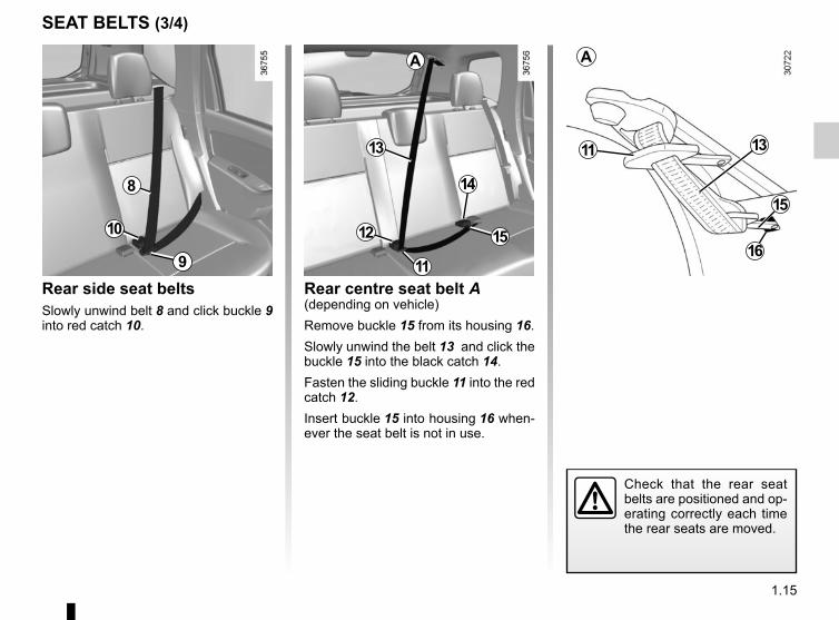
SEAT BELTS (3/4)
Rear side seat beltsSlowly unwind belt 8 and click buckle 9 into red catch 10.
Rear centre seat belt A(depending on vehicle)Remove buckle 15 from its housing 16.Slowly unwind the belt 13 and click the buckle 15 into the black catch 14.Fasten the sliding buckle 11 into the red catch 12.Insert buckle 15 into housing 16 when-ever the seat belt is not in use.
Check that the rear seat belts are positioned and op-erating correctly each time the rear seats are moved.
8
9
14
12
A
11
15
16
13
10 15
11
13
A

1.16
SEAT BELTS (4/4)The following information applies to the vehicle’s front and rear seat belts.
– No modification may be made to the component parts of the originally fitted restraint system: seat belts, seats and their mountings. For special operations (e.g. fitting child seats), contact an authorised dealer.
– Do not use devices which allow any slack in the belts (e.g. clothes pegs, clips, etc.): a seat belt which is worn too loosely may cause injury in the event of an accident.
– Never wear the shoulder strap under your arm or behind your back.– Never use the same belt for more than one person and never hold a baby or child on your lap with your seat belt around
them.– The belt should never be twisted.– Following an accident, have the seat belts checked and replaced if necessary. Always replace your seat belts as soon as
they show any signs of wear.– Make sure that the buckle is inserted into the appropriate catch.– When refitting the rear bench seat, take care that the seat belts are correctly positioned so that they can be used properly.– Ensure that no objects are placed in the area around the seat belt catch as they could prevent it from being properly se-
cured.– Make sure the seat belt catch is properly positioned (it should not be hidden away, crushed or flattened by people or ob-
jects).

1.17
METHODS OF RESTRAINT IN ADDITION TO THE FRONT SEAT BELTS (1/3)
– Have the entire restraint system checked following an accident.
– No operation whatsoever is permitted on any part of the system (air bags, electronic con-trol units, wiring) and the system components must not be reused on any other vehicle, even if iden-tical.
– To avoid premature triggering of the system which may cause injury, only qualified Network per-sonnel are authorisedto work on the methods of restraint in addi-tion to the front seat belt.
– The electric trigger system may only be tested by a specially trained technician using special equipment.
– When the vehicle is scrapped, contact an approved dealer for disposal of the pretensioner and airbag gas generators.
PretensionerWith the ignition switched on, if the vehicle is subject to a significant fron-tal impact the system may, depending on the severity of the impact, trigger a piston which instantly retracts the seat belt.The pretensioner holds the seat belt against the body, holding the occupant more securely against the seat, thus in-creasing the seat belt’s efficiency.
Load limiterAbove a certain level of impact force, this mechanism is used to limit the force of the belt against the body so that it is at an acceptable level.
Depending on the vehicle, they are composed of:– seat belt pretensioners;– chest-level load limiters;– air bags for the driver and front pas-
senger.These systems are designed to act in-dependently or together when the vehi-cle is subjected to a frontal impact.Depending on the severity of the impact, the system can trigger:– seat belt locking;– the seat belt pretensioner to hold the
occupant in the seat, and the force limiter;
– the front air bag.

1.18
METHODS OF RESTRAINT IN ADDITION TO THE FRONT SEAT BELTS (2/3)
Driver’s and passenger air bagsThese may be fitted to the front seats on the driver and passenger side (loca-tion A).Each air bag system consists of:– an air bag and gas generator fitted
on the steering wheel for the driver and in the dashboard for the front passenger;
– an electronic unit for system monitor-ing which controls the gas generator electrical trigger system;
– a special warning light å;– remote sensors.
The air bag system uses pyrotechnic principles. This explains why, when the air bag inflates, it will gener-
ate heat, produce smoke (this does not mean that a fire is about to start) and make a noise upon detonation. An air bag may inflate immediately, causing some minor, superficial grazing to the skin or other discom-fort.
OperationThis system is only operational when the ignition is switched on.If a severe frontal impact occurs, the air bag(s) inflate(s) rapidly, cushion-ing the impact of the driver’s head and chest against the steering wheel and the front passenger’s head against the dashboard. The air bag then deflates immediately so that the passengers are not impeded in any way when they get out of the vehicle.
A

1.19
METHODS OF RESTRAINT IN ADDITION TO THE FRONT SEAT BELTS (3/3)
Warnings concerning the driver’s air bag– Do not modify the steering wheel or the steering wheel boss.– Do not cover the steering wheel boss under any circumstances.– Do not attach any objects (badge, logo, clock, telephone holder, etc.) to the steering wheel boss.
– You must not remove the steering wheel (such work must only be performed by trained personnel from our Network).– When driving, do not sit too close to the steering wheel. Sit with your arms slightly bent (see the information on “Adjusting
your driving position” in Section 1). This will allow sufficient space for the air bag to inflate properly and be fully effective.
Warnings concerning the passenger air bag– Do not attach or glue any objects (badge, logo, clock, telephone holder, etc.) to the dashboard in the proximity of the air bag
housing.– Do not place anything between the dashboard and the passenger (pet, umbrella, walking stick, parcels, etc.).– The passenger must not put his or her feet on the dashboard or seat as there is a risk that serious injuries may occur. In
general, all parts of the body should be kept away from the dashboard (knees, hands, head etc.).– You should reactivate the passenger air bag as soon as you remove the child seat to ensure the protection of the front pas-
senger in the event of an impact.
A REAR-FACING CHILD SEAT MUST NOT BE FITTED TO THE FRONT PASSENGER SEAT UNLESS THE RESTRAINT SYSTEMS IN ADDITION TO THE SEAT BELT, I.E. AIR BAG, ARE DEACTIVATED.
(refer to the information on “Child safety: deactivating/activating the front passenger air bag” in Section 1)
All of the warnings below are given so that the air bag is not obstructed in any way when it is deployed and also to pre-vent the risk of serious injuries caused by items which may be dislodged when the air bag deploys.

1.20
SIDE PROTECTION DEVICESSide air bagsThese air bags may be fitted to the front seats and are deployed at the sides of the seats (door side) to protect the oc-cupants in the event of a severe side impact.
Warnings concerning the side air bag– Fitting seat covers: seats equipped with an air bag require covers specifically designed for your vehicle. Contact an approved dealer to find out if such covers are available from our Network. The use of any covers
other than those designed for your vehicle (including those designed for an-other vehicle) may affect the operation of the air bags and reduce your protec-tion.
– In the front, do not place any accessories, objects or even pets between the seatback, the door and the internal fittings. Do not cover the seatback with ob-jects such as clothes or accessories. This may prevent the airbag from operat-ing correctly or cause injury when the airbag is deployed.
– No work or modification whatsoever may be carried out on the seat or internal fittings, except by qualified personnel from our Network.

1.21
The airbag is designed to complement the action of the seat belt. Both the airbags and seat belts are integral parts of the same protection system. It is therefore essential to wear the seat belt at all times. If seat belts are not worn, the occupants are exposed to the risk of serious injury in the
event of an accident. It may also increase the risk of minor superficial injuries occurring when the airbag is deployed, although such minor injuries are always possible with airbags.If the vehicle should overturn or suffer a rear impact, however severe, the pre-tensioners and air bags are not always triggered. Impacts to the underside of the vehicle, e.g. from pavements, potholes or stones, can all trigger these systems.– No work or modification whatsoever may be carried out on any part of the
driver or passenger air bag system (air bag, electronic unit, wiring, etc.), except by qualified personnel from our Network.
– To ensure that the system is in good working order and to avoid accidental trig-gering of the system which could cause injury, only qualified personnel from our Network may work on the air bag system.
– As a safety precaution, have the air bag system checked if your vehicle has been involved in an accident, or is stolen or broken into.
– When selling or lending the vehicle, inform the user of these points and hand over this driver’s handbook with the vehicle.
– When scrapping your vehicle, contact your approved Dealer for disposal of the gas generator(s).
All of the warnings below are given so that the air bag is not obstructed in any way when it is inflated and also to prevent the risk of serious injuries caused by items which may be dislodged when the air bag inflates.
ADDITIONAL METHODS OF RESTRAINT
Operating faults
This warning light å will light up on the instrument panel when the ignition is switched on and then go out after a few seconds.If it does not light up when the ignition is switched on, or if it lights up when the engine is running, it indicates a fault in the system. In this case, fitting a child seat in the front passenger seat is PROHIBITED.Contact an approved dealer as soon as possible. Your protection will be re-duced until this fault is rectified.

1.22
CHILD SAFETY: General information (1/2)
Carrying childrenChildren, and adults, must be correctly seated and strapped in for all journeys. The children being carried in your vehi-cle are your responsibility.A child is not a miniature adult. Children are at risk of specific injuries as their muscles and bones have not yet fin-ished growing. The seat belt alone would not provide suitable protection. Use an approved child seat and ensure you use it correctly.
A collision at 30 mph (50 km/h) is the same as falling a distance of 10 metres. Transporting a
child without a restraint is the equi-valent of allowing him or her to play on a fourthfloor balcony without rail-ings.Never travel with a child held in your arms. In the event of an accident, you will not be able to keep hold of the child, even if you yourself are wearing a seat belt.If your vehicle has been involved in a road accident, replace the child seat and have the seat belts and ISOFIX fittings checked.
Never leave a child unat-tended in the vehicle.Check that your child is always strapped in and that
the belt or safety harness used is correctly set and adjusted. Avoid wearing bulky clothing which could cause the belts to slacken.Never let your child put their head or arms out of the window.Check that the child is in the correct position for the entire journey, espe-cially if asleep.
To prevent the doors being opened, use the childproof locks (refer to the informa-tion on “Locking/unlocking
the doors” in Section 1).

1.23
CHILD SAFETY: General information (2/2)
Using a child seatThe level of protection offered by the child seat depends on its ability to re-strain your child and on its installation. Incorrect installation compromises the protection it offers the child in the event of harsh braking or an impact.Before purchasing a child seat, check that it complies with the regulations for the country you are in and that it can be fitted in your vehicle. Consult an ap-proved dealer to find out which seats are recommended for your vehicle.Before fitting a child seat, read the manual and respect its instructions. If you experience any difficulties during installation, contact the manufacturer of the equipment. Keep the instructions with the seat.
Set a good example by always fas-tening your seat belt and teaching your child:– to strap themselves in correctly;– to always get in and out of the car
at the kerb, away from busy traf-fic.
Do not use a second-hand child seat or one without an instruction manual.Check that there are no objects in the vicinity of the child seat which could impede its operation.
Never leave a child unat-tended in the vehicle.Check that your child is always strapped in and that
the belt or safety harness used is correctly set and adjusted. Avoid wearing bulky clothing which could cause the belts to slacken.Never let your child put their head or arms out of the window.Check that the child is in the correct position for the entire journey, espe-cially if asleep.
1.24
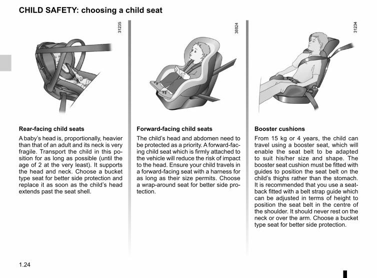
Booster cushionsFrom 15 kg or 4 years, the child can travel using a booster seat, which will enable the seat belt to be adapted to suit his/her size and shape. The booster seat cushion must be fitted with guides to position the seat belt on the child’s thighs rather than the stomach. It is recommended that you use a seat-back fitted with a belt strap guide which can be adjusted in terms of height to position the seat belt in the centre of the shoulder. It should never rest on the neck or over the arm. Choose a bucket type seat for better side protection.
Forward-facing child seatsThe child’s head and abdomen need to be protected as a priority. A forward-fac-ing child seat which is firmly attached to the vehicle will reduce the risk of impact to the head. Ensure your child travels in a forward-facing seat with a harness for as long as their size permits. Choose a wrap-around seat for better side pro-tection.
Rear-facing child seatsA baby’s head is, proportionally, heavier than that of an adult and its neck is very fragile. Transport the child in this po-sition for as long as possible (until the age of 2 at the very least). It supports the head and neck. Choose a bucket type seat for better side protection and replace it as soon as the child’s head extends past the seat shell.
CHILD SAFETY: choosing a child seat

1.25
CHILD SAFETY: mounting a child seat (1/2)Attachment via the seat beltThe seat belt must be adjusted to ensure that it is effective in the event of harsh braking or an impact.Ensure that the strap paths indicated by the child seat manufacturer are re-spected.Always check that the seat belt is cor-rectly fastened by pulling it up, then pulling it out fully whilst pressing on the child seat.Check that the seat is correctly held by moving it from side to side and back to front: the seat should remain firmly fixed.Check that the child seat has not been installed at an angle and that it is not resting against a window.
Attachment with the ISOFIX systemAuthorised ISOFIX child seats are ap-proved in accordance with regulation ECE-R44 in one of the three following cases:– ISOFIX universal 3-point forward-
facing seat;– ISOFIX semi-universal 2-point seat;– specific.For the latter two, check that your child seat can be installed by consulting the list of compatible vehicles.Attach the child seat with the ISOFIX locks, if these are provided. The ISOFIX system allows quick, easy, safe fitting.The ISOFIX system is composed of 2 rings for each rear side seat.
Before using an ISOFIX child seat that you pur-chased for another vehicle, check that its installation is
authorised. Consult the list of ve-hicles which can be fitted with the seat from the equipment manufac-turer.
No modifications may be made to the component parts of the restraint system (seat belts, ISOFIX, seats
and their mountings) originally fitted.
The seat belt must never be twisted or the tension relieved. Never pass the shoulder strap under the
arm or behind the back.Check that the seat belt has not been damaged by sharp edges.If the seat belt does not operate nor-mally, it will not protect the child. Consult an approved dealer. Do not use this seat until the seat belt has been repaired.
Do not use the child seat if it may unfasten the seat belt restraining it: the base of the seat must not rest on
the buckle and/or catch of the seat belt.

1.26
Attach the hook on the belt to one of the rings 3 (4x2 version) or 4 (4x4 version).Pull the belt so that the back of the child seat comes into contact with the back of the vehicle seat.
The third ring of each side seat is used to attach the upper strap on some child seats.Pass the belt between the seatback and the rear parcel shelf (to remove the parcel shelf: refer to Section 3 “Parcel shelf”).
The rings ISOFIX 1 are located be-tween the seatback and the seat base and are clearly visible.To ensure your child seat can be easily fitted and locked on rings 1, use access guides 2 on the child seat.
The ISOFIX anchorage points have been exclusively designed for child seats with the ISOFIX system. Never fit a different type of child seat, seat belt or other objects to these anchorage points.Check that nothing is obstructing the anchorage points.
If your vehicle has been involved in a road accident, have the ISOFIX anchorage points checked and replace your child seat.
CHILD SAFETY: mounting a child seat (2/2)
It is essential to use the boot anchorage points 3 or 4 to attach the upper belt of the child seat.
It is forbidden to use other mounting points to attach this strap.
43
1
2

1.27
CHILD SAFETY: fitting a child seat (1/6)The types of child seats indicated may not be available. Before using a differ-ent child seat, check with the manufac-turer that it can be fitted.
In the front seatThe laws concerning children travel-ling in the front passenger seat differ in every country. Consult the legislation in force and follow the indications on the diagram on the following page.Before fitting a child seat in this seat (if authorised):– deactivate the front passenger air
bag;– lower the seat belt as far as possible;– move the seat as far back as pos-
sible;– gently tilt the seatback away from
vertical (approximately 25°);– on equipped vehicles, raise the seat
base as far as possible.In all situations, reinsert the headrest to its full extent so that it does not interfere with the child seat (see the information on “Front headrests” in Section 1);
RISK OF DEATH OR SERIOUS INJURY: before fitting a child seat in this seat, check that the air bag
has been deactivated (refer to the in-formation on “Deactivating the front passenger air bag” in Section 1).
Some seats are not suitable for fitting child seats. The diagrams on the fol-lowing pages show you how to attach a child seat.
Fit the child seat in a rear seat wherever possible.Make sure that the child seat or the child’s feet do
not prevent the front seat from lock-ing correctly. Refer to the informa-tion on the “Front seat” in Section 1.Check that when installing the child seat in the vehicle it is not at risk of coming loose from its base.If you have to remove the headrest, check that it is correctly stored so that it does not come loose under harsh braking or impact.Always attach the child seat to the vehicle even if it is not in use so that it does not come loose under harsh braking or impact.
After installing the child seat, if neces-sary, the seat may be advanced (so as to leave enough space in the rear seats for passengers or other child seats). For a rear-facing child seat, do not let it touch the dashboard or move it to the furthest forward position.Do not change other settings after in-stalling the child seat.
1.28
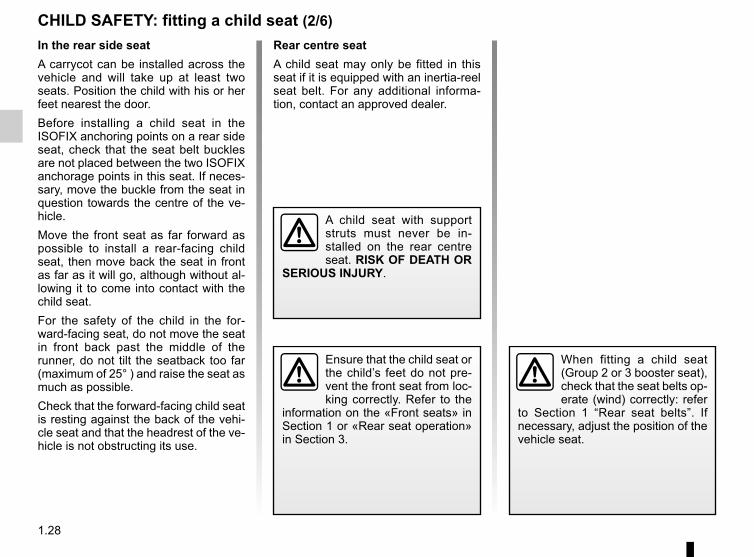
CHILD SAFETY: fitting a child seat (2/6)Rear centre seatA child seat may only be fitted in this seat if it is equipped with an inertia-reel seat belt. For any additional informa-tion, contact an approved dealer.
In the rear side seatA carrycot can be installed across the vehicle and will take up at least two seats. Position the child with his or her feet nearest the door.Before installing a child seat in the ISOFIX anchoring points on a rear side seat, check that the seat belt buckles are not placed between the two ISOFIX anchorage points in this seat. If neces-sary, move the buckle from the seat in question towards the centre of the ve-hicle.Move the front seat as far forward as possible to install a rear-facing child seat, then move back the seat in front as far as it will go, although without al-lowing it to come into contact with the child seat.For the safety of the child in the for-ward-facing seat, do not move the seat in front back past the middle of the runner, do not tilt the seatback too far (maximum of 25° ) and raise the seat as much as possible.Check that the forward-facing child seat is resting against the back of the vehi-cle seat and that the headrest of the ve-hicle is not obstructing its use.
Ensure that the child seat or the child’s feet do not pre-vent the front seat from loc-king correctly. Refer to the
information on the «Front seats» in Section 1 or «Rear seat operation» in Section 3.
A child seat with support struts must never be in-stalled on the rear centre seat. RISK OF DEATH OR
SERIOUS INJURY.
When fitting a child seat (Group 2 or 3 booster seat), check that the seat belts op-erate (wind) correctly: refer
to Section 1 “Rear seat belts”. If necessary, adjust the position of the vehicle seat.

1.29
CHILD SAFETY: fitting a child seat (3/6)
Using a child safety system which is not approved for this vehicle will not correctly protect the baby or child.
They risk serious or even fatal injury.
³ Check the status of the air bag before fitting a child seat or allowing a passenger to use the seat.
Vehicles without air bag OR with air bag deactivated
RISK OF DEATH OR SERIOUS INJURY: before installing a child/baby seat on the front passenger seat,
check that the air bag has been de-activated (refer to “Deactivating the front passenger air bag” at the end of the paragraph).
Child seat attached using the ISOFIX mounting
ü Seat which allows an ISOFIX child seat to be fitted.
± The rear seats are fitted with an anchorage point which allows a forward-facing ISOFIX child seat with universal approval to be fitted. The an-chorage points are located under the luggage compartment carpet and are indicated by a marking.The size of the ISOFIX child seat is in-dicated by a letter:– A, B and B1: for forward-facing seats
in group 1 (9 to 18 kg);– C: rear-facing seats in group 1 (9 to
18 kg);– D and E: shell seat or rear-facing
seats in group 0 or 0+ (less than 13 kg);
– F and G: cots in group 0 (less than 10 kg).
² Seat not suitable for fitting child seats.
¬ Seat which allows a child seat with “Universal” approval to be attached by a seat belt.
Only if the seat is equipped with an inertia-reel belt.1
1

1.30
CHILD SAFETY: fitting a child seat (4/6)
Child seat attached using the belt
¬ Seat which allows a child seat with “Universal” approval to be attached by a seat belt.
Only if the seat is equipped with an inertia-reel belt.
Using a child safety system which is not approved for this vehicle will not correctly protect the baby or child.
They risk serious or even fatal injury.
² Seat not suitable for fitting child seats.
Vehicles with passenger air bag not deactivated
RISK OF DEATH OR SERIOUS INJURY: never fit a child seat to this seat.
Child seat attached using the ISOFIX mounting
ü Seat which allows an ISOFIX child seat to be fitted.
± The rear seats are fitted with an anchorage point which allows a forward-facing ISOFIX child seat with universal approval to be fitted. The an-chorage points are located under the luggage compartment carpet and are indicated by a marking.The size of the ISOFIX child seat is in-dicated by a letter:– A, B and B1: for forward-facing seats
in group 1 (9 to 18 kg);– C: rear-facing seats in group 1 (9 to
18 kg);– D and E: shell seat or rear-facing
seats in group 0 or 0+ (less than 13 kg);
– F and G: cots in group 0 (less than 10 kg).
1
1

1.31
CHILD SAFETY: fitting a child seat (5/6)
(5) RISK OF DEATH OR SERIOUS INJURY: before fitting a child seat on the front passenger seat, check that the air bag has been deactivated (refer to the information on “Deactivating the front passenger air bag” in Section 1).(6) RISK OF DEATH OR SERIOUS INJURY: never fit a child seat to this seat.
The table below summarises the information already shown on the diagram on the previous pages, to ensure the regula-tions in force are respected.
Type of child seat Weight of the child
Seat size
Front passenger seat without air bag or with air
bag deactivated (1) (5)
Front passenger seat with air bag
without deactivation(1) (6)
Rear side
seats
Rear centre seat(7)
Carrycot fitted across the vehicleApproved for group 0
< 10 kg F - G X XU-IL (2)
U
Rear-facing shell seatApproved for group 0 or 0+
< 13 kg9 to 18 kg
D, E U XU-IL (3)
U
Rear-facing seatApproved for group 0+ and 1 9 to 18 kg C U X
U-IL (3)
U
Forward-facing seatApproved for group 1 9 to 18 kg A, B,
B1 X XU - IUF
- IL(4)
U
Booster seatApproved for group 2 and 3
15 kg to 25 kg and 22 to 36 kg
– X XU (4)
U
1.32
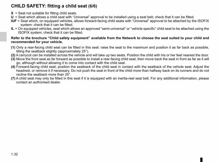
CHILD SAFETY: fitting a child seat (6/6)X = Seat not suitable for fitting child seats.U = Seat which allows a child seat with “Universal” approval to be installed using a seat belt; check that it can be fitted.IUF = Seat which, on equipped vehicles, allows forward-facing child seats with “Universal” approval to be attached by the ISOFIX
system: check that it can be fitted.IL = On equipped vehicles, seat which allows an approved “semi-universal” or “vehicle specific” child seat to be attached using the
ISOFIX system; check that it can be fitted.Refer to the brochure “Child safety equipment” available from the Network to choose the seat suited to your child and recommended for your vehicle.(1) Only a rear-facing child seat can be fitted in this seat: raise the seat to the maximum and position it as far back as possible,
tilting the seatback slightly (approximately 25°).(2) A carrycot can be installed across the vehicle and will take up two seats. Position the child with his or her feet nearest the door.(3) Move the front seat as far forward as possible to install a rear-facing child seat, then move back the seat in front as far as it will
go, although without allowing it to come into contact with the child seat.(4) Forward-facing child seat; position the seatback of the child seat in contact with the seatback of the vehicle seat. Adjust the
headrest, or remove it if necessary. Do not push the seat in front of the child more than halfway back on its runners and do not recline the seatback more than 25°.
(7) A child seat may only be fitted in this seat if it is equipped with an inertia-reel seat belt. For any additional information, please contact an authorised dealer.

1.33
To deactivate the passenger airbag, with the ignition off, press and turn button 1 to the OFF position.With the ignition switched back on, it is essential to check that warning light 2,
], is lit up on the instrument panel.This warning light remains conti-nuously lit to let you know that you can fit a child seat.
Deactivating the front passenger air bag(depending on vehicle)To fit a rear-facing child seat on the front passenger seat, you must deacti-vate the front passenger air bag if your vehicle is fitted with air bag deactiva-tion.
CHILD SAFETY: deactivating/activating the front passenger air bag (1/3)
The passenger air bag must be activated or deactivated with the ignition off.If handled when the igni-
tion is on, the warning light å comes on.Switch the ignition off then on again to reset the air bag in accordance with the lock position.
21

1.34
DANGERSince operation of the front passenger airbag is not compatible with the position
of a rear-facing child seat, NEVER fit a restraint system for a rear-fac-ing child in a seat protected by an ACTIVATED front AIRBAG. This can cause the CHILD’S DEATH or SERIOUS INJURY.
CHILD SAFETY: deactivating/activating the front passenger air bag (2/3)
The markings on the dashboard and labels A on each side of the passenger sun visor 3 (as shown above) repeat these instructions.
A
3
A

1.35
Operating faultsIt is forbidden to fit a rear-facing child seat to the front passenger seat if the air bag activation/deactivation system is faulty.Allowing any other passenger to sit in that seat is not recommended.Contact your approved dealer as soon as possible.
Activation of the front passenger air bag(depending on vehicle)You should reactivate the airbag as soon as you remove the child seat from the front passenger seat to ensure the protection of the front passenger in the event of an impact.To reactivate the airbag: with the vehi-cle at a standstill and with the ignition switched off, press and turn button 1 to the ON position.With the ignition switched on, it is es-sential to check that warning light 2,
], is off.
CHILD SAFETY: deactivating/activating the front passenger air bag (3/3)
21
The passenger air bag must be activated or deactivated with the ignition off.If handled when the igni-
tion is on, the warning light å comes on.Switch the ignition off then on again to reset the air bag in accordance with the lock position.
1.36
REAR VIEW MIRRORS
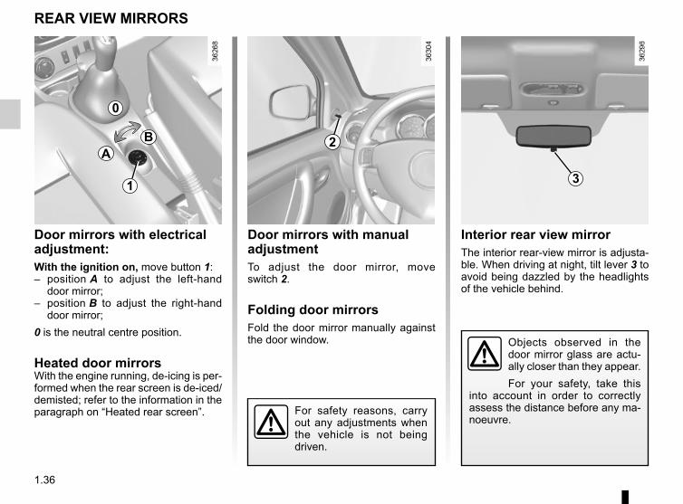
Door mirrors with electrical adjustment:With the ignition on, move button 1:– position A to adjust the left-hand
door mirror;– position B to adjust the right-hand
door mirror;0 is the neutral centre position.
Heated door mirrorsWith the engine running, de-icing is per-formed when the rear screen is de-iced/demisted; refer to the information in the paragraph on “Heated rear screen”.
Interior rear view mirrorThe interior rear-view mirror is adjusta-ble. When driving at night, tilt lever 3 to avoid being dazzled by the headlights of the vehicle behind.
Door mirrors with manual adjustmentTo adjust the door mirror, move switch 2.
Folding door mirrorsFold the door mirror manually against the door window.
For safety reasons, carry out any adjustments when the vehicle is not being driven.
0
BA
1 3
2
Objects observed in the door mirror glass are actu-ally closer than they appear.For your safety, take this
into account in order to correctly assess the distance before any ma-noeuvre.

1.37
DRIVER’S POSITION, LEFT-HAND DRIVE (1/2)
1 2 3 5 127 8 11 161510 17
35
9 13
1837 3638 34 33 192032
27 26282931 30
21222324
25
1464

1.38
DRIVER’S POSITION, LEFT-HAND DRIVE (2/2)The fittings described DEPEND ON THE VEHICLE VERSION AND COUNTRY.
1 Side air vent.2 Side demister outlet.3 Stalk for:
– direction indicator lights,– exterior lights,– front fog lights,– rear fog light,– horn.
4 Audible warning5 Instrument panel.6 Location for driver’s airbag.7 – Steering column stalk for winds-
creen and rear screen wash/wiper.
– On-board computer information readout control.
8 Ignition switch.9 Hazard warning lights switch.10 Centre air vents.11 Electric central locking switch.
12 Central demister outlet.13 Location for radio, navigation system
or storage compartments.14 Location for passenger airbag.15 Side demister outlet.16 Side air vent.17 Passenger airbag activation/deacti-
vation switch.18 Glove compartment19 Activation/deactivation control for
the parking distance control.20 Rear screen and door mirror de-
icing control21 ECO mode switch.22 ESC control (4x4 (4WD) version).23 Activation/deactivation controls for
the Stop and Start function.24 4x2 (2WD), 4x4 (4WD) mode selec-
tor or storage compartment.
25 Cigarette lighter or accessories socket.
26 Handbrake.27 Door mirror adjustment control.28 Gearstick.29 LPG control30 Accessories socket.31 Bottle holders.32 Heating and ventilation controls.33 Cruise control/speed limiter main
control.34 Radio remote control.35 Cruise control/speed limiter controls.36 Beam height adjustment control.37 Bonnet release control.38 Fuse box.

1.39
DRIVING POSITION, RIGHT-HAND DRIVE (1/2)
1 2 3 7 9 10 11 15
34
8 13
33
19 161718
5 64 14
35
12
2122
20
2324
28 26273031 29 25
32
1.40
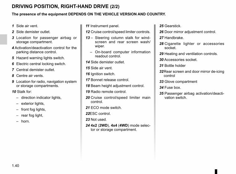
DRIVING POSITION, RIGHT-HAND DRIVE (2/2)The presence of the equipment DEPENDS ON THE VEHICLE VERSION AND COUNTRY.
1 Side air vent.2 Side demister outlet.3 Location for passenger airbag or
storage compartment.4 Activation/deactivation control for the
parking distance control.5 Hazard warning lights switch.6 Electric central locking switch.7 Central demister outlet.8 Centre air vents.9 Location for radio, navigation system
or storage compartments.10 Stalk for:
– direction indicator lights,– exterior lights,– front fog lights,– rear fog light,– horn.
11 Instrument panel.12 Cruise control/speed limiter controls.13 – Steering column stalk for wind-
screen and rear screen wash/wiper.
– On-board computer information readout control.
14 Side demister outlet.15 Side air vent.16 Ignition switch.17 Bonnet release control.18 Beam height adjustment control.19 Radio remote control.20 Cruise control/speed limiter main
control.21 ECO mode switch.22ESC control.23 Not used.24 4x2 (2WD), 4x4 (4WD) mode selec-
tor or storage compartment.
25 Gearstick.26 Door mirror adjustment control.27 Handbrake.28 Cigarette lighter or accessories
socket.29 Heating and ventilation controls.30 Accessories socket.31 Bottle holder32 Rear screen and door mirror de-icing
control33 Glove compartment34 Fuse box.35 Passenger airbag activation/deacti-
vation switch.
1.41
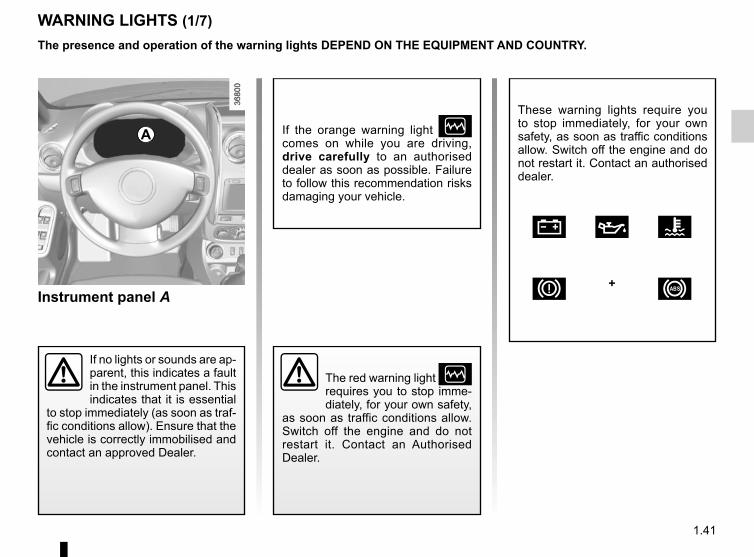
Instrument panel A
WARNING LIGHTS (1/7)
A
If no lights or sounds are ap-parent, this indicates a fault in the instrument panel. This indicates that it is essential
to stop immediately (as soon as traf-fic conditions allow). Ensure that the vehicle is correctly immobilised and contact an approved Dealer.
If the orange warning light Ò comes on while you are driving, drive carefully to an authorised dealer as soon as possible. Failure to follow this recommendation risks damaging your vehicle.
The red warning light Ò requires you to stop imme-diately, for your own safety,
as soon as traffic conditions allow. Switch off the engine and do not restart it. Contact an Authorised Dealer.
The presence and operation of the warning lights DEPEND ON THE EQUIPMENT AND COUNTRY.
These warning lights require you to stop immediately, for your own safety, as soon as traffic conditions allow. Switch off the engine and do not restart it. Contact an authorised dealer.
Ú À Ô
D + x

1.42
WARNING LIGHTS (2/7)
A
D Handbrake “on” warning light and brake circuit inci-
dent warning lightThis comes on when the ignition is switched on. If it comes on during brak-ing or driving and, depending on the ve-hicle, is accompanied by a beep, it in-dicates that the fluid level in the circuit is low; it may be dangerous to continue driving – please contact an authorised dealer.
Ò Warning light malfunction (red or orange)
Urgent stop warning light (red)This lights up when the ignition is switched on and goes out as soon as the engine is started. It lights up at the same time as other warning lights, and is accompanied by a beep.It requires you to stop immediately, for your own safety, as soon as traffic con-ditions allow. Switch off the engine and do not restart it.Contact an approved Dealer.
Warning light (orange)This lights up when the ignition is switched on and goes out as soon as the engine is started. It may comes on in conjunction with other warning lights on the instrument panel.It means you should drive very care-fully to an authorised dealer as soon as possible. If you fail to follow this rec-ommendation, you risk damaging your vehicle.
Ô Coolant temperature warn-ing light
It goes out as soon as the engine starts.If this remains lit while driving and, de-pending on the vehicle, is accompanied by a beep, this means the engine is overheating. Stop and allow the engine to run at idle speed for a minute or two. The temperature should drop. If not, stop the engine. Let it cool down before checking the coolant level. Contact an authorised dealer if necessary.
The presence and operation of the warning lights DEPEND ON THE EQUIPMENT AND COUNTRY.
1.43
WARNING LIGHTS (3/7)
A
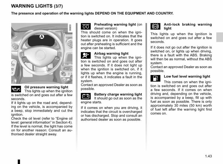
À Oil pressure warning lightThis lights up when the ignition
is switched on and goes out after a few seconds.If it lights up on the road and, depend-ing on the vehicle, is accompanied by a beep, stop immediately and cut the ignition.Check the oil level (refer to “Engine oil level: general information” in Section 4). If the level is normal, the light has come on for another reason: Consult an au-thorised dealer straight away.
É Preheating warning light (on diesel version)
This should come on when the igni-tion is switched on. It indicates that the heater plugs are in operation. It goes out after preheating is sufficient and the engine can be started.
å Airbag warning lightThis lights up when the igni-
tion is switched on and goes out after a few seconds. If it does not light up when the ignition is switched on, if it lights up when the engine is running, or if it flashes, it indicates a fault in the system.Contact an approved Dealer as soon as possible.
Ú Battery charge warning lightIt should go out as soon as the
engine starts.If it comes on when you are driving, it indicates that the circuit is overcharged or has discharged. Stop and consult an authorised dealer as soon as possible.
x Anti-lock braking warning light
This lights up when the ignition is switched on and goes out after a few seconds.If it does not go out after the ignition is switched on, or lights up when driving, there is a fault with the ABS. Braking will then be as normal, without the ABS system.Contact an approved Dealer as soon as possible.
L Low fuel level warning lightThis comes on when the igni-
tion is switched on and goes out after a few seconds. If it comes on when driving and, depending on the vehicle, is accompanied by a beep, fill up with fuel as soon as possible. There is only approximately 30 miles (50 km) worth of fuel left after the warning light first comes on.
The presence and operation of the warning lights DEPEND ON THE EQUIPMENT AND COUNTRY.
1.44
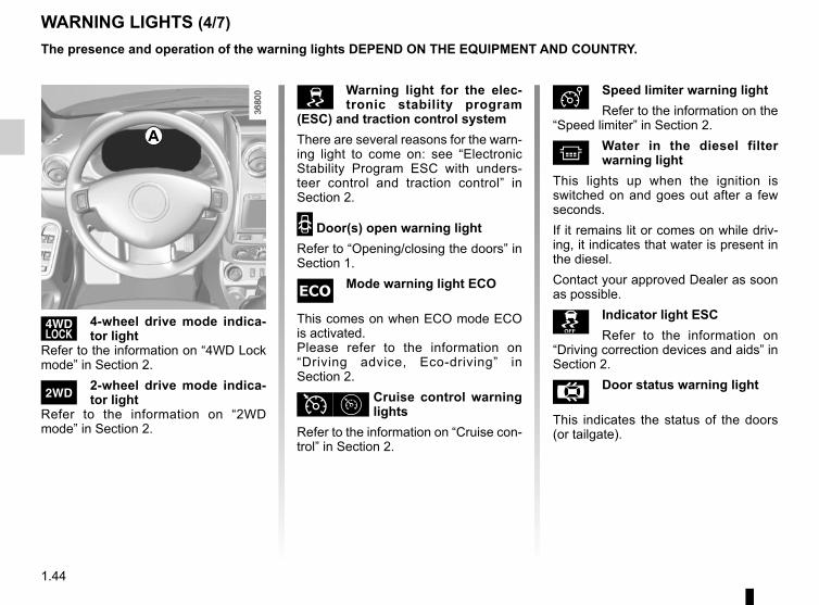
’ 4-wheel drive mode indica-tor light
Refer to the information on “4WD Lock mode” in Section 2.
‘ 2-wheel drive mode indica-tor light
Refer to the information on “2WD mode” in Section 2.
Ð Speed limiter warning lightRefer to the information on the
“Speed limiter” in Section 2.
^ Water in the diesel filter warning light
This lights up when the ignition is switched on and goes out after a few seconds.If it remains lit or comes on while driv-ing, it indicates that water is present in the diesel.Contact your approved Dealer as soon as possible.
Indicator light ESCRefer to the information on
“Driving correction devices and aids” in Section 2.
Å Door status warning light
This indicates the status of the doors (or tailgate).
WARNING LIGHTS (4/7)
A
Warning light for the elec-tronic stability program
(ESC) and traction control systemThere are several reasons for the warn-ing light to come on: see “Electronic Stability Program ESC with unders-teer control and traction control” in Section 2.
2 Door(s) open warning lightRefer to “Opening/closing the doors” in Section 1.
Mode warning light ECO
This comes on when ECO mode ECO is activated.Please refer to the information on “Driving advice, Eco-driving” in Section 2.
Ϧ Cruise control warning lights
Refer to the information on “Cruise con-trol” in Section 2.
The presence and operation of the warning lights DEPEND ON THE EQUIPMENT AND COUNTRY.

1.45
á Main beam headlight tell-tale light
k Dipped beam headlight tell-tale
g Front fog light tell-tale light
f Rear fog light tell-tale
c Left-hand direction indicator tell-tale
b Right-hand direction indica-tor tell-tale
ä æ Gear change indicatorThis lights up to advise
you to change to a higher gear (up arrow) or lower gear (down arrow).
Excess speed warning lightA beep will sound and the warn-
ing light will come on if the vehicle ex-ceeds 70 mph (120 km/h).
The presence and operation of the warning lights DEPEND ON THE EQUIPMENT AND COUNTRY.
A
# Engine oil change warning light
This lights up on the instrument panel when an oil change is required.Change the oil or have it changed as soon as possible.Only the distance travelled between two oil changes is taken into account; the time interval between two oil changes is not. The oil should always be changed when the first threshold is reached, i.e. either the distance travelled or the inter-val specified in your vehicle’s mainte-nance document. This means you may have to change the oil before the warn-ing light comes on.Refer to the information on the “Oil change” in Section 4.
V Rear screen de-icing/de-misting indicator light
d Direction indicator tell-tale light
ê Engine immobiliser system warning light
This light performs several functions.Refer to the information on the “Engine immobiliser” in Section 1.
WARNING LIGHTS (5/7)
1.46
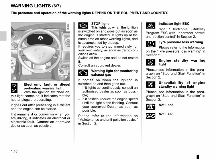
6 Electronic fault or diesel preheating warning light With the ignition switched on,
this light comes on; it indicates that the heater plugs are operating.It goes out after preheating is sufficient and the engine can be started.If it remains lit or comes on when you are driving, it indicates an electrical or electronic fault. Contact an approved dealer as soon as possible.
Æ STOP lightThis lights up when the ignition
is switched on and goes out as soon as the engine is started. It lights up at the same time as other warning lights, and is accompanied by a beep.It requires you to stop immediately, for your own safety, as soon as traffic con-ditions allow.Switch off the engine and do not restart it.Consult an approved dealer.
Ä Warning light for monitoring exhaust gas
It comes on when the ignition is switched on and then goes out.– If it lights up continuously, consult an
authorised dealer as soon as possi-ble;
– If it flashes, reduce the engine speed until the light stops flashing. Contact your approved Dealer as soon as possible.
Please refer to the information on “Maintenance and anti-pollution advice” in Section 2.
ù Indicator light ESCSee “Electronic Stability
Program ESC with understeer control and traction control” in Section 2.
Tyre pressure loss warningPlease refer to the information
on the “Tyre pressure loss warning” in Section 2.
Engine standby warning light
Please see information in the para-graph on “Stop and Start Function” in Section 2.
Unavailability of engine standby warning light
Please see information in the para-graph on “Stop and Start Function” in Section 2.
Ü Not used.
î Not used.
A
The presence and operation of the warning lights DEPEND ON THE EQUIPMENT AND COUNTRY.
WARNING LIGHTS (6/7)

1.47
WARNING LIGHTS (7/7)
Warning lights on console B
] Front passenger air bag de-activation warning light.
Refer to the information on “Child safety: deactivating, activating the front passenger airbag".
B
ß Seat belt reminder lightIt comes on when the engine
is started if the driver and/or passenger seat belt is not fastened (depending on the vehicle). When the vehicle is being driven, it comes on and a beep sounds for approximately 2 minutes until the driver’s seat belt is fastened.
The presence and operation of the warning lights DEPEND ON THE EQUIPMENT AND COUNTRY.

1.48
DISPLAY AND INDICATORS (1/2)
Speedometer 2 (kph or mph)
12
Rev counter 1 (rpm x 1,000) Automatic gearbox display 3This indicates the gear engaged. Refer to information on the “Automatic gear-box” in Section 2.
3

1.49
DISPLAY AND INDICATORS (2/2)
In 4x4 (4WD) mode on rough ter-rain, there is a risk that incorrect in-formation on the fuel level may be displayed. Wait until you are on flat ground again for a stable reading of the oil level indicators.
Fuel gauge warning light 4 or 5The number of squares lit shows the fuel level. When it is at minimum, the squares disappear and the low fuel level warning light comes on, depen-ding on the vehicle.
Trip computer and warning system A or BRefer to the information on the “Trip computer and warning system” in Section 1.
4 5
A B

1.50
ON-BOARD COMPUTER (1/6)
12
The display of information shown below DEPENDS ON THE VEHICLE EQUIPMENT AND COUNTRY.
Trip computer and warning system 1
Display selection key 2Press button 2 to repeatedly to scroll through the following information:a) Total mileage recorderb) Trip mileage recorderc) Fuel consumedd) Average fuel consumptione) Current fuel consumption
f) Estimated rangeg) Distance travelledh) Average speedi) Oil change intervalj) Reset the tyre pressurek) speed limiter.l) Timem) Outside temperature information.Refer to the table on the following pages showing display examples.
Resetting the trip mileageTo reset the trip mileage recorder, the display must show the Trip mileometer function.Press and hold button 2.
1.51
Interpreting some of the values displayed after resettingThe values showing average fuel consumption, range and average speed will become more stable and re-liable the further you travel after pres-sing the reset button.For the first few miles after pressing the reset key you will notice that the range increases as you travel. This range takes into account the average fuel consumption since the last time the reset button was pressed. Therefore, the fuel consumption may decrease when:
– the vehicle stops accelerating,– the engine reaches its operating
temperature (engine cold when reset button pressed),
– when driving from a built-up area onto the open road.
Therefore, if the average fuel consumption decreases, the range will increase.
– You may also notice that the ave-rage fuel consumption increases when the vehicle is stationary and the engine idling.This is normal, since the computer takes account of fuel used during idling.
Manually resetting the journey para-meters: with the display showing one of the journey parameters, press the button 2 until the display is reset.Automatically resetting the journey parameters: the reset is automatic when the capacity of one of the memo-ries is exceeded.
ON-BOARD COMPUTER (2/6)The display of information shown below DEPENDS ON THE VEHICLE EQUIPMENT AND COUNTRY.

1.52
Examples of display selections by repeatedly pressing 2 Interpreting the display selected
Display A Display B
a) Total mileage recorder.
b) Trip mileage recorder.
– c) Fuel used since the last time the reset button was pressed.
–d) Average fuel consumption since the last time the reset button was
pressed.This value is displayed after driving 400 metres and takes into ac-count the distance travelled and the fuel used since the last time the reset button was pressed.
ON-BOARD COMPUTER (3/6)The display of information shown below DEPENDS ON THE VEHICLE EQUIPMENT AND COUNTRY.

1.53
Examples of display selections by repeatedly pressing 2 Interpreting the display selected
Display A Display B
– e) Current fuel consumption.This value is displayed after a speed of approximately 20 mph (30 km/h) is reached.
–
f) Estimated range with remaining fuel.This range takes into account the average fuel consumption since the last time the reset button was pressed.The value is displayed after driving around 400 metres.
– g) Distance travelled since the last time the reset button was pressed.
–h) Average speed since the last reset.
The value is displayed after driving around 400 metres.
ON-BOARD COMPUTER (4/6)The display of information shown below DEPENDS ON THE VEHICLE EQUIPMENT AND COUNTRY.

1.54
ON-BOARD COMPUTER (5/6)
Examples of display selections by repeatedly pressing 2 Interpreting the display selected
Display A Display B
j) Mileage before serviceDistance remaining until the next oil change.There are several scenarios:– mileage before oil change service less than 1000 miles Warning light Ê on the instrument panel comes on accompanied by the message “1000 miles”.
– mileage before oil change service 0 miles. Warning light Ê on the instrument panel comes on accompanied by the message “--- miles”.
The distance appears on the display for approximately 8 seconds when the ignition is switched on as soon as the distance is less than or equal to 1000 miles.The vehicle requires an oil change as soon as possible.
Note: depending on the vehicle, the mileage before an oil change varies according to the driving style (frequent driving at low speed, door-to-door journeys, extensive use at idle speed, towing a trailer etc.). The distance remaining until the next oil change can therefore decrease more quickly in some cases than the actual distance travelled.The oil change intervals are independent of the vehicle’s maintenance schedule: please refer to your vehicle’s maintenance do-cument.Resetting: to reset the mileage before an oil change, press and hold the display reset button for approximately 10 seconds until the display shows the range permanently.
The display of information shown below DEPENDS ON THE VEHICLE EQUIPMENT AND COUNTRY.

1.55
Examples of display selections by repeatedly pressing 2 Interpreting the display selected
Display A Display B
j) Tyre pressure reset.Please refer to the information on the “Tyre pressure loss warning” in Section 2.
k) Recommended cruise control and speed limiter speed (if acti-vated).Refer to the information on the “Speed limiter” and “Cruise control” in Section 2.
l) Time.
m) Exterior temperature.
ON-BOARD COMPUTER (6/6)The display of information shown below DEPENDS ON THE VEHICLE EQUIPMENT AND COUNTRY.

1.56
STEERING WHEEL, POWER-ASSISTED STEERINGPower Assisted SteeringWith the engine running, do not leave the steering wheel at full lock while sta-tionary as this may damage the power-assisted steering pump.With the engine switched off, or if there is a system fault, it is still possible to turn the steering wheel. The force re-quired will be greater.
Adjusting the steering wheelDepending on the vehicle, the steering wheel position is adjustable.Lift lever 1 and place the steering wheel in the required position; raise the lever to lock the steering wheel in place.Make sure that the steering wheel is correctly locked.
For safety reasons, only adjust the steering wheel when the vehicle is station-ary.
Never switch off the igni-tion when travelling down-hill, and avoid doing so in normal driving (assistance
is not provided).
1

1.57
CLOCK
Setting the timeDisplay ADisplay the “Clock” display on the ins-trument panel by pressing the button 1.
If the electrical supply is cut (battery disconnected, broken supply wire, etc.), the clock will lose its time set-ting.The clock must be reset.
For your safety, we recom-mend that you do not adjust the clock while driving.
Press and hold button 1 to enter the hour setting mode.When only the hours flash, press button 1 briefly, to scroll through them.Press and hold button 1 to enter the minute setting mode.When only the minutes flash, press button 1 briefly, to scroll through them.Confirm by pressing and holding button 1.
1
A
1.58
AUDIBLE AND VISUAL SIGNALS
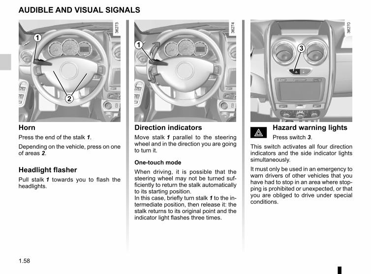
HornPress the end of the stalk 1.Depending on the vehicle, press on one of areas 2.
Headlight flasherPull stalk 1 towards you to flash the headlights.
Direction indicatorsMove stalk 1 parallel to the steering wheel and in the direction you are going to turn it.
One-touch modeWhen driving, it is possible that the steering wheel may not be turned suf-ficiently to return the stalk automatically to its starting position.In this case, briefly turn stalk 1 to the in-termediate position, then release it: the stalk returns to its original point and the indicator light flashes three times.
1
2
1
é Hazard warning lightsPress switch 3.
This switch activates all four direction indicators and the side indicator lights simultaneously.It must only be used in an emergency to warn drivers of other vehicles that you have had to stop in an area where stop-ping is prohibited or unexpected, or that you are obliged to drive under special conditions.
3

1.59
e Switching off the lightsFrom the main beam head-
lights position, pull the stalk 1 towards you, then turn the end of the stalk 1
until the e symbol appears by the mark 2.From the dipped beam headlights posi-tion, turn the end of the stalk 1 until the
e symbol appears by the mark 2.
EXTERIOR LIGHTING AND SIGNALS (1/2)
š Side lightsTurn the end of stalk 1 until the
symbol is opposite mark 2.
k Dipped beam headlights
Turn the end of stalk 1 until the symbol is opposite mark 2.An indicator light on the instrument panel will come on.
á Main beam headlightsWith the dipped beam head-
lights lit, push stalk 1. This indicator light on the instrument panel comes on.To return to the dipped headlight posi-tion, pull the stalk 1 towards you again.
Before driving at night, check that the electrical equipment is operating correctly and adjust the headlight beams (if your vehicle is not carrying its normal load). As a general precaution, check that the lights are not ob-scured (by dirt, mud, snow or objects being transported).
11 2

1.60
EXTERIOR LIGHTING AND SIGNALS (2/2)
g Front fog lightsTurn the centre ring 3 of
the stalk until the symbol is opposite mark 2.The fog lights only light up if the exterior lights have been switched on. An indi-cator light on the instrument panel then lights up.Do not forget to switch off the fog lights when they are no longer needed, to avoid inconveniencing other road users.
h Rear fog lightsTurn the centre ring 3 on
the stalk until the symbol faces mark 2.The fog lights only light up if the exterior lights have been switched on. An indi-cator light on the instrument panel then lights up.Remember to switch off the these lights when they are no longer required to avoid inconveniencing other road users.
e Turning off the fog lights
Turn the centre ring 3 of the stalk until the symbol is opposite mark 2.The corresponding indicator light goes out on the instrument panel.The front and rear fog lights switch off when the exterior lights are switched off.
2 3
Daytime running lights function(front lights only)The daytime running lights come on automatically with no action on stalk 1 when the engine is started, and they go off once the engine is switched off. They are deactivated when the main beams, dipped beams or side lights are lit.
Lights-on warning buzzerIf the lights are on, a warning beep sounds when the driver’s door is opened to warn you that the lights are still on.
1

1.61
Examples of positions for adjusting control A according to the load
Control A
4x2 4x4
Driver alone or with front passenger 0 0
Driver with one front passenger and three rear passengers 1 1
Driver with one front passenger, three rear passengers and luggage 3 2
Driver only and luggage 4 3
The control A is used to adjust the height of the headlight beams accord-ing to the load.Turn control A anticlockwise to lower the beams and clockwise to raise them.
ADJUSTING THE HEADLIGHT BEAM HEIGHT (1/2)
A

1.62
ADJUSTING THE HEADLIGHT BEAM HEIGHT (2/2)
Temporary adjustmentOpen the bonnet and identify the mark-ing B next to one of the front headlight projectors.For each headlight, using a screw-driver, turn the screw 1 by a quarter turn towards the - symbol to lower the beams.Return to the starting point once your trip is over: turn the screw 1 by a quar-ter turn towards the + symbol to raise the beams. When driving on the left in a left-
hand drive vehicle (or vice versa), you must adjust your lights tempo-rarily during your stay.
1
B

1.63
WINDSCREEN WASH, WIPE (1/2)
n Windscreen wiperWith the ignition on, move
stalk 1 around the steering wheel:A Park.B Intermittent wiping.
The wipers will pause for several seconds between sweeps.
C Normal wiping speed.D Fast wiping speed.
s Windscreen wiperWith the ignition on, pull stalk 1
towards you.A brief pull will trigger a single sweep of the wipers, in addition to the wind-screen washer.A longer pull will trigger three sweeps of the wipers, in addition to the wind-screen washer.
In frosty weather, make sure that the wiper blades are not stuck by ice (risk of motor overheating).Keep an eye on the condition of the blades. They should be replaced as soon as they become less efficient. This will occur approximately once a year. Clean your windscreen reg-ularly.If you switch off the ignition before switching off the windscreen wiper (position A) the blades will stop at random on the windscreen.After switching the ignition back on, simply move stalk 1 to position A to place them in the park position.
Before touching the wind-screen (washing the vehi-cle, de-icing, cleaning the windscreen, etc.) move
stalk 1 to position A (park). Risk of injury and/or damage.
When working in the engine compartment, ensure that the windscreen wiper stalk is in position A (park). Risk
of injury.
1
ABC
D

1.64
WINDSCREEN WASH, WIPE (2/2)
Y Rear screen wiperWith the ignition on, turn the
end of stalk 1 to align the symbol with mark 2. Before using the rear wiper, check
that no object is obstructing the travel of the blade.In frosty weather, make sure that the wiper blades are not stuck by ice (to avoid the risk of the motor over-heating).Keep an eye on the condition of the blades. They should be replaced as soon as they become less efficient. This will occur approximately once a year. Clean your windscreen reg-ularly.
p Rear screen washer/wiper
With the ignition on, turn the end of stalk 1 to align the symbol with mark 2.When the stalk is released, it returns to the rear wipe position.
Before touching the wind-screen (washing the vehi-cle, de-icing, cleaning the windscreen, etc.) move
stalk 1 to position A (park). Risk of injury and/or damage.
1
2

1.65
FUEL TANK (1/6)
Petrol and diesel versionsUsable capacity of the fuel tank: 50 litres approximately.Depending on the vehicle, to open the fuel filler flap A, place your finger in opening B and pull.To close, push the fuel filler flap A by hand as far as it will go. Depending on the vehicle, the cap 1 is unlocked using the ignition key. If not, it will be connected to the vehicle by a strip of plastic. For details on filling the fuel tank, please refer to the information on “Filling with fuel”.
Fuel filler cap: this is spe-cific to the vehicle type. If you have to replace it, make sure the new cap is of the
same type. Contact an approved dealer.Never place the cap near a source of heat or flame.Do not wash the filler area with a high-pressure washer.
A
3
C
B
There is a cap holder 3 on the fuel filler flap for holding the cap when the tank is being filled.Depending on the vehicle, lift lever 2 to unlock the fuel filler flap A. Open it, then unscrew fuel filler cap 1.
1
2
1.66
FUEL TANK (2/6)Vehicles running on ethanol-based fuelAlways use unleaded petrol or fuel containing a maximum of 85 percent ethanol (E85).In very cold conditions, it may be very difficult or even impossible to start the engine.Note: you may notice an increase in fuel consumption with this type of fuel.When the fuel is changed the engine must adjust, which may cause minor in-conveniences for a few minutes (longer starting times, cutting out, etc.).
Fuel gradeAlways use a high-grade fuel that complies with the legislation in force in each country. It must conform to the specifications given on label C inside the fuel filler flap.Refer to the “Engine specifications” table in Section 6.Petrol versionIt is essential to use unleaded petrol. The octane rating (RON) must conform to the specifications given on the label inside fuel filler flap C.Diesel versionsIt is essential to use diesel fuel that con-forms to the specifications given on the label inside fuel flap C.
Do not mix even small amounts of petrol (un-leaded or E85) with diesel.Do not use ethanol-based
fuel if your vehicle is not compatible with this fuel.Do not add additive to the fuel other-wise you risk damaging the engine.

1.67
FUEL TANK (3/6)
Filling with fuelInsert the nozzle to open the valve and insert it fully before turning it on to fill the fuel tank (risk of splashing).Keep the nozzle in this position throughout the entire filling operation. When the pump cuts out automatically at the end of the filling procedure, a maximum of two further filling attempts may be made, as there must be suffi-cient space in the fuel tank to allow for expansion.Make sure that no water enters the fuel tank during filling. The valve and its sur-round must remain clean. Persistent fuel odour
If you notice a persistent smell of fuel you should:
– stop the vehicle when traffic conditions allow it and switch off the ignition;
– switch on the hazard warning lights and ask your passengers to leave the vehicle and stay clear of the traffic;
– contact an authorised dealer.
Petrol versionsUsing leaded petrol will damage the antipollution system and may lead to a loss of warranty.To ensure that the fuel tank is not filled with leaded petrol, the fuel tank filler neck contains a restrictor fitted with a foolproof system which only allows the nozzle for unleaded petrol to be used (at the pump).
Vehicle fitted with the Stop and Start functionTo fill up with fuel, the engine must be stopped (and not on standby): stop the engine (please refer to the information on “Starting and stop-ping the engine” in Section 2).
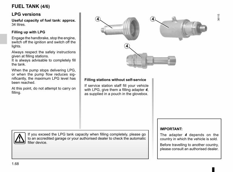
1.68
LPG versionsUseful capacity of fuel tank: approx. 34 litres.
Filling up with LPGEngage the handbrake, stop the engine, switch off the ignition and switch off the lights.Always respect the safety instructions given at filling stations.It is always advisable to completely fill the tank.When the pump stops delivering LPG, or when the pump flow reduces sig-nificantly, the maximum LPG level has been reached. At this point, do not attempt to carry on filling.
If you exceed the LPG tank capacity when filling completely, please go to an accredited garage or your authorised dealer to check the automatic filler device.
FUEL TANK (4/6)
Filling stations without self-serviceIf service station staff fill your vehicle with LPG, give them a filling adapter 4, as supplied in a pouch in the glovebox.
IMPORTANT:The adapter 4 depends on the country in which the vehicle is sold.Before travelling to another country, please consult an authorised dealer.
4 4
4

1.69
FUEL TANK (5/6)
Filling stations with self-serviceWe recommend that you wear gloves when handling the LPG pistol. Open your vehicle’s tank cover and unscrew the cap 5 from the end piece of the LPG filler 6.Carefully follow the information explain-ing how to refill using the LPG distribu-tor.
When the pump finishes or if it has dif-ficulties operating, this means that the maximum tank fill level (80%) has been reached. The filling will stop as soon as you re-lease the button. Release the stop lever (a small amount of gas may be re-leased), lift the pistol and place it on the distributor. Replace the cap 5 to avoid any water or foreign bodies from entering the system.
5
6

1.70
No modifications what-soever are permitted on any part of the fuel supply system (computers, wiring,
fuel circuit, injector, protection covers, etc.) as this may be danger-ous (such work must be undertaken by qualified Network personnel).
Priming bulb (diesel version)After a breakdown caused by com-pletely running out of fuel, the system must be reprimed before the engine is restarted:Note: the bulb is always located on the right-hand side of the engine compart-ment. Operate the priming bulb 8 until the fuel flows through the hose 7.If the engine does not start after several attempts, contact an approved dealer.
The engine may be hot when working in close prox-imity. In addition, the engine cooling fan may come on at
any moment.Risk of injury.
FUEL TANK (6/6)
7 8

2.1
Section 2: Driving(Advice on use relating to fuel economy and the environment)
Running in, Ignition switch . . . . . . . . . . . . . . . . . . . . . . . . . . . . . . . . . . . . . . . . . . . . . . . . . . . . . . . . . 2.2Starting/stopping the engine . . . . . . . . . . . . . . . . . . . . . . . . . . . . . . . . . . . . . . . . . . . . . . . . . . . . . . . 2.3Stop and Start Function . . . . . . . . . . . . . . . . . . . . . . . . . . . . . . . . . . . . . . . . . . . . . . . . . . . . . . . . . . . 2.7Special features of petrol versions . . . . . . . . . . . . . . . . . . . . . . . . . . . . . . . . . . . . . . . . . . . . . . . . . . 2.10Special features of diesel versions . . . . . . . . . . . . . . . . . . . . . . . . . . . . . . . . . . . . . . . . . . . . . . . . . . 2.11Special features of LPG versions . . . . . . . . . . . . . . . . . . . . . . . . . . . . . . . . . . . . . . . . . . . . . . . . . . . 2.12Driving advice, eco-driving . . . . . . . . . . . . . . . . . . . . . . . . . . . . . . . . . . . . . . . . . . . . . . . . . . . . . . . . 2.15Maintenance and antipollution advice . . . . . . . . . . . . . . . . . . . . . . . . . . . . . . . . . . . . . . . . . . . . . . . . 2.20Environment . . . . . . . . . . . . . . . . . . . . . . . . . . . . . . . . . . . . . . . . . . . . . . . . . . . . . . . . . . . . . . . . . . . 2.21Tyre pressure loss warning . . . . . . . . . . . . . . . . . . . . . . . . . . . . . . . . . . . . . . . . . . . . . . . . . . . . . . . . 2.22Gear lever, Handbrake . . . . . . . . . . . . . . . . . . . . . . . . . . . . . . . . . . . . . . . . . . . . . . . . . . . . . . . . . . . 2.29Transmission: 4-wheel drive (4WD) . . . . . . . . . . . . . . . . . . . . . . . . . . . . . . . . . . . . . . . . . . . . . . . . . 2.30Driver correction devices/aids . . . . . . . . . . . . . . . . . . . . . . . . . . . . . . . . . . . . . . . . . . . . . . . . . . . . . . 2.34Speed limiter . . . . . . . . . . . . . . . . . . . . . . . . . . . . . . . . . . . . . . . . . . . . . . . . . . . . . . . . . . . . . . . . . . . 2.38Cruise control . . . . . . . . . . . . . . . . . . . . . . . . . . . . . . . . . . . . . . . . . . . . . . . . . . . . . . . . . . . . . . . . . . 2.41Automatic gearbox. . . . . . . . . . . . . . . . . . . . . . . . . . . . . . . . . . . . . . . . . . . . . . . . . . . . . . . . . . . . . . . 2.45Parking distance control . . . . . . . . . . . . . . . . . . . . . . . . . . . . . . . . . . . . . . . . . . . . . . . . . . . . . . . . . . 2.49Reversing camera . . . . . . . . . . . . . . . . . . . . . . . . . . . . . . . . . . . . . . . . . . . . . . . . . . . . . . . . . . . . . . . 2.51
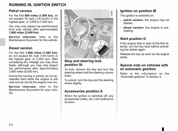
2.2
Petrol versionFor the first 600 miles (1,000 km), do not exceed 78 mph (130 km/h) in the highest gear, or 3,000 to 3,500 rpm.You may only expect top performance from your vehicle after approximately 1,800 miles (3,000 km).Service intervals: refer to the Maintenance Document for the vehicle.
Diesel versionFor the first 1,000 miles (1,500 km), do not exceed 80 mph (130 km/h) in the highest gear, or 2,500 rpm. After completing this mileage you may drive faster, although you may only expect top performance after approximately 3,600 miles (6,000 km).During the running in period, do not ac-celerate hard while the engine is still cold and do not let the engine over-rev.Service intervals: refer to the Maintenance Document for your vehi-cle.
RUNNING IN, IGNITION SWITCH
Stop and steering lock position StTo lock: remove the key and turn the steering wheel until the steering column locks.To unlock: turn the key and the steering wheel slightly.
Accessories position AWhen the ignition is switched off, any accessories (radio, etc.) will continue to function.
Ignition on position MThe ignition is switched on:– petrol version: the engine may be
started.– diesel version: the engine is pre-
heating.
Start position DIf the engine fails to start at the first at-tempt, turn the key back before activat-ing the starter again.Release the key as soon as the engine starts.
Special note on vehicles with an automatic gearboxRefer to the information on the “Automatic gearbox” in Section 2.

2.3
LPG versionsThe engine is always started using petrol:– activate the starter without accelerat-
ing;– release the key as soon as the
engine starts.The system will automatically deter-mine the switchover from petrol to LPG.When operating on LPG, the fuel gauge may indicate a drop in the petrol level and the on-board computer will not op-erate. Under certain winter conditions the system may delay or disable operation with LPG.After stopping the engine, if the envi-ronmental conditions are once again suitable, the system may once again permit LPG mode.
Starting the engineIn very cold conditions (temperatures below –20°C): so that it is easier to start the engine, switch on the ignition for several seconds before starting the engine.When starting the engine, if the outdoor temperature is very low (below -10°C): hold down the clutch pedal until the engine starts.Make sure the engine immobiliser is not activated. Refer to the information on the “Engine immobiliser” in Section 1.
Petrol injection– Turn the key to the start position
without depressing the accelera-tor.
– Release the key as soon as the engine starts.
É Diesel injection
Turn the ignition key to ignition “On” po-sition M, and hold this position until the preheating warning light goes out.Turn the key to starter position D with-out depressing the accelerator pedal.Release the key as soon as the engine starts.
STARTING, STOPPING THE ENGINE (1/4)At temperatures close to 0°C or less, it is recommended to use ECO mode to maximise the use of LPG. Please refer to the information on “Driving advice, Eco-driving” in Section 2.To enable the system to operate smoothly and to prevent any wear to the vehicle’s electric petrol pump, the petrol tank should always be around 1/4 full.

2.4
vehicles with an automatic gearboxBefore starting, move the lever to posi-tion P.Refer to the information on the “Automatic gearbox” in Section 2.
Stopping the engineWith the engine idling, turn the key back to “Stop” position St.
Special noteDepending on the vehicle, accessories (e.g. radio) stop working either when the engine is switched off or when the driver’s door is opened or when the doors are locked.
Driver’s responsibilityNever leave an animal, child or adult who is not self-sufficient alone on your
vehicle, even for a short time.They may pose a risk to themselves or to others by starting the engine, activating equipment such as the electric windows or locking the doors, for example.Also, in hot and/or sunny weather, please remember that the tempera-ture inside the passenger compart-ment increases very quickly.Never switch off the ignition before the vehicle has stopped completely. Switching off the engine disables the assistance equipment: brakes, steering, etc., and additional seatbelt devices.The steering is locked when the key is removed.RISK OF DEATH OR SERIOUS INJURY.
STARTING, STOPPING THE ENGINE (2/4)
Do not park the vehicle or run the engine in locations where combustible sub-stances or materials such
as grass or leaves can come into contact with a hot exhaust system.

2.5
STARTING, STOPPING THE ENGINE (3/4)
Remote engine start-upActivationIf the vehicle is so equipped, press the unlocking button 1 briefly, then press the remote start button 3 twice for about 3 seconds each time.
OperationThis function allows remote starting of the engine.To do this, press the locking button 2, followed by the remote start button 3 for about 3 seconds.
2
3
The remote engine start-up operates if:– the lever is in neutral for vehicles
with a manual or sequential gearbox;– the lever is in position P for vehicles
with an automatic gearbox;– the ignition is off and no key is in-
serted into the ignition switch;– the bonnet is closed;– all of the opening elements (doors
and luggage compartment) are closed and locked when you leave the vehicle.
This function also lets you programme the engine to start, in order to heat or ventilate the passenger compartment up to 24 hours before using the vehicle.The configuration and the program-ming are done using the multimedia display 4, : refer to the multimedia in-structions for your vehicle.
1
4
Special note for vehicles fitted with the “Wake up every 2 hours” function.In the event of use of the function two days in succession, you must drive at least 10 minutes between the two uses. Risk of engine oil wear.Please see your vehicle’s multime-dia instructions.

2.6
STARTING, STOPPING THE ENGINE (4/4)
Do not use the engine remote start-up function or its programming when:– the vehicle is in a garage or in a confined space.Risk of poisoning or suffocation by exhaust gas emissions.
– the vehicle is covered with a protective cover.Fire hazard.
– the bonnet is open or before it opens.Risk of burns or serious injury.
Depending on the country, the use of the remote starting function or its programming can be prohibited by the legis-lation and/or the regulations in force.Before using this function, check the legislation and/or the regulations for the country in force.

2.7
For manual gearboxes:– the gearbox is in neutral;and– the clutch pedal is released.
If the warning light flashes, this means that the clutch pedal is not sufficiently released;and
– the vehicle speed is less than ap-proximately 7 mph (3 km/h).
In all vehicles, the warning light appears on the instrument panel to warn you when the engine is on standby.The vehicle equipment remain opera-tional while the engine is stopped.
STOP AND START function (1/3)This system enables a reduced fuel consumption and lower greenhouse gas emissions.The system is activated automatically when the vehicle is started.While driving, the system stops the engine (standby) when the vehicle is at a standstill (traffic jam, traffic lights, etc).
Conditions for engine standbyThe vehicle has set off from where it was parked;For automatic or sequential gear-box:– The gearbox is in position D, M or N;and– the brake pedal is depressed (suffi-
ciently hard);and– the accelerator pedal is not de-
pressed;and– the vehicle’s speed is zero for around
one second.The engine remains on standby if posi-tion P is selected, or if position N is se-lected with the handbrake engaged and the brake pedal released. Engine on standby - braking
assistance is no longer op-erational.
The ignition must be switched off before leaving the vehicle (please see sec-tion on “Starting, stopping
the engine”).
Keep your vehicle station-ary when the engine is on standby (shown by the
warning light on the instrument panel).
If you get out of the vehicle, a beep notifies you that the engine is on standby and has not been switched off.
If the engine stalls while the system is in operation, pressing the clutch pedal right down will start it again.

2.8
STOP AND START function (2/3)
Conditions preventing the standby of the engineCertain conditions prevent the system from using the engine standby function, including when:– reverse gear is engaged;– the bonnet is not locked;– the outdoor temperature is too low or
too high (less than around 0 °C or higher than around 30 °C);
– the battery is not sufficiently char-ged;
– if available, the vehicle is in “4WD Lock” mode (please see the section “Transmission: 4-wheel drive (4WD)” in Section 2);
– for vehicles with an automatic or sequential gearbox, the gradient is steeper than approximately 12%;
– the engine temperature is too low;– the anti-pollution system is required;or– ...
The warning light lights up on the instrument panel to alert you that engine standby is not available.
To fill up with fuel, the engine must be stopped (and not on standby): always stop the engine (please see “Starting, stopping the engine”).
Deactivate the Stop and Start function for any opera-tion performed in the engine compartment.
Preventing the engine from standing byIn certain situations, when negotiating a junction for instance, it is possible to keep the engine running so as to be ready to move off quickly.Automatic or sequential gearboxKeep the vehicle stationary without pressing too hard on the brake pedal.Manual gearboxKeep the clutch pedal pressed right down.
Conditions for coming out of engine standbyFor automatic or sequential gear-box:– The brake pedal is released, position
D or M engaged or,– the brake pedal is released with
the gear lever in position N and the handbrake off, or
– the brake pedal is pressed again, with position N engaged and the handbrake applied, or
– position R is engaged, or– the accelerator pedal is pressed.For manual gearboxes:– The gearbox is in neutral and the
clutch pedal is slightly depressed, or– the engine is in gear and the clutch
pedal is pressed right down.

2.9
Deactivating, activating the functionPress switch 1 to deactivate the func-tion. Warning light 2 in the switch lights up.Pressing again will reactivate the system. Warning light 2 in switch 1 goes out.
STOP AND START function (3/3)The system is automatically reacti-vated each time the vehicle is started (see “Starting, stopping the engine” in Section 2).
Operating faultsWhen the warning light 2 built in to switch 1 is lit, the system is deacti-vated.Please consult an authorised dealer.
Before getting out of the vehicle, you must switch off the ignition (please see section on “Starting, stop-
ping the engine”).
1 2
Special feature of the automatic engine re-startUnder certain conditions, the engine can restart on its own in order to gua-rantee your safety and comfort.This can occur especially when:– The outdoor temperature is too low
or too high (less than around 0°C or higher than around 30°C);
– the battery is not sufficiently char-ged;
– the vehicle speed is above 3 mph (5 km/h) (downhill slope, etc.);
– repeated pressing on the brake pedal or braking system require-ment;
– ...
Special note: with the engine on standby, press switch 1 to restart the engine.
Special note: for some of these conditions the automatic restarting of the engine is inhibited if a front door is open.

2.10
SPECIAL FEATURES OF PETROL VERSIONSThe following operating conditions:– driving for long periods when the low
fuel level warning light is lit;– using leaded petrol;– using oil or fuel additives which are
not approved by the manufacturer.Or operating faults such as:– faulty ignition system, running out of
fuel or disconnected spark plugs re-sulting in the engine misfiring or cut-ting out when driving;
– loss of power,may cause the catalytic converter to overheat, reducing its efficiency which may irreparably damage it and cause heat damage to the vehicle.
If you notice any of the above operating faults, have the necessary repairs car-ried out as soon as possible by an ap-proved Dealer.These faults may be avoided by reg-ularly taking your vehicle to your ap-proved dealer at the intervals speci-fied in your Maintenance Service Document.
Starting problemsTo avoid damaging the catalytic con-verter, do not keep trying to start the engine (using the start button, or by pushing or towing the vehicle) without having identified and corrected the starting fault.If the fault cannot be identified, do not continue to try and start the engine, but contact an approved dealer.
Do not park the vehicle or run the engine in locations where combustible sub-stances or materials such
as grass or leaves can come into contact with a hot exhaust system.

2.11
SPECIAL FEATURES OF DIESEL VERSIONSDiesel engine speedDiesel engines are fitted with an injec-tion pump which prevents the engine speed being exceeded irrespective of the gear selected.
If the Ä and Ò warning lights come on, consult an approved dealer as soon as possible.When driving, depending on the fuel grade used, it is possible that white smoke may be emitted. This is due to the exhaust particle filter being cleaned automatically, and does not affect the way the vehicle runs.
Running out of fuelIf the tank has been completely drained, the system must be reprimed after the tank is refilled: see information on the “Fuel tank” in Section 1 before restarting the engine.
Precautions to be taken in winterTo avoid any faults in icy weather:– ensure that the battery is always fully
charged;– always keep the diesel tank rela-
tively full to avoid water vapour con-densing in it and accumulating at the bottom of the tank.
Do not park the vehicle or run the engine in locations where combustible sub-stances or materials such
as grass or leaves can come into contact with a hot exhaust system.

2.12
Fuel gauge warning light AThe warning lights A (4 green lights and 1 red light) indicate the level in the LPG tank.The red warning light indicates the fuel tank.The amount of LPG indicated is an in-dicative value.The red warning light indicates that the tank is almost empty and that the engine is operating using the fuel tank (approximately 11 to 13 litres).
SPECIAL FEATURES OF LPG VERSIONS (1/3)LPG vehiclesThese vehicles operate using petrol or LPG.They have two separate tanks.
What is LPG?LPG stands for Liquefied Petroleum Gas.It can be readily identified by its charac-teristic smell.
An LPG installation on a vehicle may lead to changes to the vehicle’s features, compared to
petrol versions. This may relate to the number of seats, mass (usable capacity) and towing capacity. Contact an authorised dealer.
LPG/petrol fuel mode selection control CThis enables the driver to switch from one fuel to another.
Green warning light DA lit warning light indicates that LPG mode is active.Rapid flashing of the warning light D indicates that the system is waiting for the necessary conditions to switch to LPG mode.
Yellow warning light BA lit warning light indicates that petrol mode is active.
If the yellow warning light is on while the green warning light flashes slowly and a beep is heard, please take
your vehicle to an authorised dealer for inspection.
A
D C B

2.13
SPECIAL FEATURES OF LPG VERSIONS (2/3)
Changing fuel while drivingTo switch from petrol to LPGPress control C. The vehicle will switch to LPG the next time the accelerator pedal is pressed.The LPG fuel level A is activated. The yellow warning light B goes out and the green warning light D flashes quickly to confirm that LPG has been selected, then stops flashing when LPG mode is active.
Pressing control C stops the beep from sounding and only the yellow warning light B stays on.
To switch from LPG to petrol.Release the accelerator pedal and press the control C.Petrol mode is indicated by the yellow warning light B.
Automatic switch to petrolThe system automatically switches to petrol mode if there is no more LPG remaining in the tank. You will be in-formed by:– the green D and yellow B warning
lights coming on;– a beep sounds.Pressing control C stops the beep from sounding and only the yellow warning light B stays on.Depending on the vehicle, under certain conditions of use, the system may opt to temporarily switch back to petrol mode (the green warning light D flashes wi-thout any beep sounding, for example, during strong acceleration). Once the suitable conditions are present once again, it will automatically switch back to LPG mode. After several unsuccess-ful attempts, the system may decide to remain in petrol mode for the current driving session. A further attempt may be made after the engine has been at a complete stop for 1 minute.
D C B
A
C

2.14
SPECIAL FEATURES OF LPG VERSIONS (3/3)
If driving under severe conditionsIf driving under severe conditions (hea-vily laden vehicle, high outside tempe-rature, starting on a steep slope, etc), you are recommended to switch to petrol mode.At temperatures close to 0°C or less, it is recommended to use ECO mode to maximise the use of LPG. Please refer to the information on “Driving advice, Eco-driving” in Section 2.
In the event of an accidentThe main precautions to be taken are the same as with petrol vehicles:– apply the handbrake;– stop the engine (a safety device that
stops LPG from entering the engine is automatically triggered);
– switch off the ignition;– observe local regulations.
LPG has a very specific smell so you will be able to detect any leaks easily. If you smell gas in your vehi-
cle or immediately surrounding your vehicle:– switch to petrol mode immedia-
tely and make sure there are no flames or sources of fire near the vehicle;
– go to an authorised dealer.
Do not touch, hit or dis-mantle any part of the LPG system components.
Operating faultIn the event of a fault which may affect the correct operation of the engine, the system automatically switches from LPG to petrol mode.This is confirmed by:– the appearance of the yellow war-
ning light B;– slow flashing of the green warning
light D;– a beep sounds.

2.15
Fuel consumption is accredited in ac-cordance with a standard regulatory method. Identical for all manufactur-ers, this enables vehicles to be com-pared with one another. Consumption in real time depends on vehicle usage conditions, the equipment fitted and the user’s driving style. To optimise fuel consumption, please refer to the follow-ing advice.Depending on the vehicle, you will have various functions which enable you to lower your fuel consumption:– the rev counter;– gear change indicator;– ECO mode – activated by the ECO
button.
Gear change indicator 1To obtain optimum consumption levels, a warning light on the instrument panel lets you know the best time to move up or down a gear:
Š move up a gear;
‰ move down a gear.
DRIVING ADVICE, ECO-DRIVING (1/5)
1

2.16
DRIVING ADVICE, ECO-DRIVING (2/5)
ECO modeECO mode is a function which opti-mises fuel consumption. This acts on certain consumption components, such as the engine.
Activating the functionPress switch 3.
The 2 warning light comes on on the instrument panel to confirm activa-tion.
While driving, it is possible to leave the ECO mode temporarily in order to im-prove engine performance.To do this, press the accelerator pedal firmly and fully.ECO mode is reactivated when you take pressure off the accelerator pedal.
Disabling the functionPress switch 3.
The 2 light goes out on the in-strument panel to confirm deactivation.
2
3

2.17
DRIVING ADVICE, ECO-DRIVING (3/5)– Avoid sudden acceleration.– Brake as little as possible. If you an-
ticipate an obstacle or bend in ad-vance, you may then simply release the accelerator pedal.
– Do not try to maintain the same speed up a hill, accelerate no more than you would on the level. Keep your foot in the same position on the accelerator pedal.
– Double declutching and accelerating before switching off are unnecessary in modern vehicles.On versions with an automatic gear-box, it is preferable to keep the gear lever in position D.
Vehicles with 4x4 (4WD) trans-missionOn flat, level ground, with the vehi-cle unladen, you are recommended to start in second gear.
Driving advice, Eco-drivingBehaviour– Drive carefully for the first few miles
until the engine reaches its normal operating temperature, rather than let it warm up while the vehicle is sta-tionary.
– Speed is expensive.– Sporty driving uses a lot of fuel: drive
with a light right foot.– Do not overrev the engine in the in-
termediate gears. You should always use the highest
gear possible.
Driving problemsOn the driver’s side, only use mats specially adapted for the vehicle and attached
to prefitted devices. Check regularly to make sure they are secure. Do not overlay several mats.Risk of pedals jamming.

2.18
DRIVING ADVICE, ECO-DRIVING (4/5)
Your vehicle has a greater ground clearance than an ordinary passenger vehicle. This gives it a higher centre
of gravity, making it more suscep-tible to rolling during sudden or ag-gressive manoeuvres, or when cor-nering at high speeds.Take extra care when the vehicle is loaded (in particular when the load is on the roof).Ensure that all passengers are wea-ring their seat belts.A label A affixed to the sun visor re-minds you of this.
A
Tyres– An underinflated tyre increases fuel
consumption.– The use of non-recommended tyres
can increase fuel consumption.

2.19
DRIVING ADVICE, ECO-DRIVING (5/5)– In vehicles fitted with air condi-
tioning, it is normal to observe an increase in fuel consumption (es-pecially in urban conditions) when it is used. For vehicles fitted with manual air conditioning, switch off the system when it is not required.Advice for reducing consumption and therefore helping to preserve the environment:If the vehicle has been parked in the sun, open the doors for a few mo-ments to let the hot air escape before starting the engine.
– Do not leave an empty roof rack fitted to the vehicle.
– It is better to fit a trailer for bulky ob-jects.
– When towing a caravan, fit a wind deflector and adjust it carefully.
– Avoid using the car for door-to-door calls (short journeys with long waits in between) because the engine never reaches its normal operating temperature.
Advice on use– Favour ECO mode.– Electricity is fuel; switch off all the
electrical components which are not really needed. However (safety first), keep your lights on when the visibility is bad (“see and be seen”).
– Use the air vents. Driving with the windows open at 60 mph (100 km/h) will increase fuel consumption by 4%.
– Never fill the fuel tank right to the brim to avoid overflow.

2.20
MAINTENANCE AND ANTIPOLLUTION ADVICE Your vehicle complies with criteria for recycling and recovering vehicles at the end of their service life, which will come into force in 2015.Some of the parts on your vehicle have been designed to be recycled later.These parts are easily removable in order to be collected and reprocessed in recycling networks.Furthermore, by virtue of its design, moderate fuel consumption and initial settings, your vehicle also conforms to current anti-pollution regulations. The manufacturer is actively striving to reduce pollutant exhaust gas emis-sions and to save energy. However, the fuel consumption of your vehicle and the level of pollutant exhaust gas emissions are also your responsibility. Ensure that it is maintained and used correctly.
MaintenanceIt is important to remember that fail-ure to respect anti-pollution regulations could lead to legal action being taken against the vehicle owner.In addition, replacing engine, fuel supply system and exhaust compo-nents with parts other than those origi-nally recommended by the manufac-turer may alter your vehicle so that it no longer complies with anti-pollution regulations.Have your vehicle adjusted and checked by an authorised dealer, in ac-cordance with the instructions given in your maintenance schedule: they will have all the equipment necessary for ensuring that your vehicle is maintained to its original standard.
Engine adjustments– Air filter, fuel filter: a choked ele-
ment will reduce efficiency. It must be replaced.
– Idle speed: no adjustment is needed.
Exhaust gas monitoring systemThe exhaust gas monitoring system will detect any operating faults in the vehi-cle’s antipollution system.If this system malfunctions, toxic sub-stances may be released into the at-mosphere or damage may occur.
Ä This warning light on the in-strument panel will indicate if
there are any faults in the system:This lights up when the ignition is switched on and goes out when the engine is started.– If it lights up continuously, consult an
approved Dealer as soon as possi-ble;
– if it flashes, reduce the engine speed until the light stops flashing. Contact an authorised dealer as soon as pos-sible.

2.21
ENVIRONMENTEmissionsYour vehicle has been designed to emit fewer greenhouse gases (CO2) while in use, and therefore to consume less fuel (eg. 140 g/km, equivalent to 5.3 l/100 km for a diesel vehicle).Our vehicles are also equipped with a particle filter system including a cata-lytic converter, an oxygen sensor and an active carbon filter (the latter pre-vents vapour from the fuel tank being released into the open air).For certain diesel vehicles, this system also has a particle filter to reduce the volume of soot particles emitted.
Please make your own contribution towards protecting the environment too– Worn parts replaced in the course of
routine vehicle maintenance (vehi-cle battery, oil filter, air filter, batter-ies, etc.) and oil containers (empty or filled with used oil) must be disposed of through specialist organisations.
– At the end of the vehicle’s service life, it should be sent to approved centres to ensure that it is recycled.
– In all cases, comply with local legis-lation.
RecyclingYour vehicle is 85% recyclable and 95% recoverable.To achieve these objectives, many of the vehicle components have been de-signed to enable them to be recycled. The materials and structures have been carefully designed to allow these components to be easily removed and reprocessed by specialist companies.In order to preserve raw material re-sources, this vehicle incorporates nu-merous parts made from recycled plas-tics or renewable materials (vegetable or animal-derived materials such as cotton or wool).
Your vehicle has been designed with respect for the environment in mind for its entire service life: during production, use and at the end of its life.This commitment is illustrated by the of the manufacturer eco² signature.
ManufactureYour vehicle has been manufactured at a factory which complies with a policy to reduce the environmental impact on the surrounding areas (reduction of water and energy consumption, visual and noise pollution, atmospheric emis-sions and waste water; sorting and re-using waste).

2.22
TYRE PRESSURE LOSS WARNING (1/7)
When fitted to the vehicle, this system notifies the driver if one or more tyres lose pressure.
A
System identificationThere are two tyre pressure loss warn-ing systems:– System A: can be seen on the
label A in the vehicle. To verify its presence, open the driver’s door.
– System B: can be seen on the label A in the vehicle.
A

2.23
TYRE PRESSURE LOSS WARNING (2/7)
SYSTEM AOperating principleThis system detects a loss of pressure in one of the tyres by measuring the wheel speed while driving.
Warning light 1 comes on to alert the driver in the event of insuffi-cient pressure (deflated wheel, punc-tured tyre, etc.).
Operating conditionsThe system has to be reset with an in-flation pressure equal to that written on the tyre inflation pressure label. Otherwise it risks not giving a reliable warning in the event of a significant loss of pressure. Please refer to the informa-tion on “Tyre pressures” in Section 4.In the following situations, the system risk coming into action late or not func-tioning correctly:– system not reset after reinflation or
any operation on the wheels;– system badly reset: different inflation
pressures from the recommended pressures;
– significant change in load or distribu-tion of load on one side of the vehi-cle;
– sporty driving with strong accelera-tion;
– driving on snowy or slippery surface;– driving with snow chains;
– fitting a single new tyre;– use of tyres not approved by the net-
work.– ...
1
This function is an additio-nal driving aid.However, the function does not take the place of the
driver. It cannot, therefore, under any circumstances replace the vi-gilance or the responsibility of the driver.Check the tyre pressures, including the emergency spare wheel, once a month.

2.24
TYRE PRESSURE LOSS WARNING (3/7)
SYSTEM A (cntd.)Resetting the standard level for the tyre pressuresThis should be done:– after each reinflation or readjustment
of the pressure of one of the tyres;– when the standard tyre pressure
needs to be changed to adapt to usage conditions (empty, carrying a load, motorway driving, etc.);
– after changing a wheel;– after using the tyre inflation kit;– after changing wheels around.It should always be done after checking the tyre pressure of all four tyres when cold.Tyre pressures must correspond to the current usage of the vehicle (empty, carrying a load, motorway driving, etc.).
DisplayInflate tyres and SEt tP
The warning light comes on (not flashing).This indicates that at least one tyre is flat or punctured.In the event of a flat tyre, inflate the rel-evant tyre.In the event of a puncture, change the tyre or consult an authorised dealer.Check and readjust the pressure of the four tyres when cold, and launch the reset of the tyre pressure reference value.
Warning light goes out after launching the reinitialisation of the tyre pressure reference value.
2
3
Resetting procedureWith the ignition on:– repeatedly press the button 3 to
select the “SEt tP” function on the display 2;
– press and hold (around 3 seconds) the button 3 to start initialisation. The flashing, lasting around five seconds, followed by a constant display of the message «SEt tP" indicates that the reset request for the tyre pressure reference value has been taken into account.
Reinitialisation is carried out after a few minutes’ driving.
The sudden loss of pressure in a tyre (burst tyre, etc.) cannot be de-tected by the system.
2.25
TYRE PRESSURE LOSS WARNING (4/7)
SYSTEM A (cntd.)Relaunch SEt tP
Warning light flashes for several seconds, then stays on.It indicates that the request to reset the reference tyre pressure value must be relaunched.System unavailable
Warning light flashes for several seconds, then stays on.Indicates that the vehicle is fitted with an emergency spare wheel which is smaller than the other four and is fitted to the vehicle.System to be checked
The warning light flashes for several seconds, then stays on, along
with the orange warning light Ò. They indicate a system fault. Please consult an authorised dealer.
Readjustment of tyre pressuresThe tyre pressures must be adjusted when cold (please refer to the label lo-cated on the edge of the driver’s door).If tyre pressures cannot be checked when the tyres are cold, the recom-mended pressures should be increased by 0.2 to 0.3 bar (3 PSI).Never deflate a hot tyre.After each reinflation or readjustment of the tyre pressure, launch the reinitiali-sation of the tyre pressure reference value.
Replacing wheels/tyresOnly use equipment approved by the brand network, or the system risks being activated late or not operating correctly. Please see the information on “Tyres” in Section 5.
After each change of wheel/tyre, rea-djust the tyre pressure and launch the reset of the tyre pressure reference value.
Emergency spare wheelIf fitted on the vehicle, readjust the tyre pressure and launch the reinitialisation of the tyre pressure reference value.
Inflation kitOnly use equipment approved by the brand network, or the system risks being activated late or not operating correctly. Please refer to “Tyre inflation kit” in Section 5.After using the tyre inflation kit, readjust the tyre pressure and launch the reini-tialisation of the tyre pressure reference value.

2.26
TYRE PRESSURE LOSS WARNING (5/7)
SYSTEM BOperating principleEach wheel (except for the emergency spare wheel) has a sensor in the infla-tion valve which periodically measures the tyre pressure while driving.
Warning light 1 comes on to alert the driver in the event of insuffi-cient pressure (deflated wheel, punc-tured tyre, etc.).
Resetting the standard level for the tyre pressuresThis should be performed:– when the standard tyre pressure
needs to be changed to adapt to usage conditions (empty, carrying a load, motorway driving, etc.);
– after changing wheels around;– after changing a wheel.It should always be done after checking the tyre pressure of all four tyres when cold.Tyre pressures must correspond to the current usage of the vehicle (empty, carrying a load, motorway driving, etc.).
This function is an addi-tional driving aid.However, the function does not take the place of the
driver. It cannot, therefore, under any circumstances replace the vig-ilance or the responsibility of the driver.Check the tyre pressures, including the emergency spare wheel, once a month.
1

2.27
TYRE PRESSURE LOSS WARNING (6/7)Note:The standard tyre pressure cannot be less than that recommended and indi-cated on the door frame.
DisplayCheck tyre pressure
The warning light comes on (not flashing).This indicates that at least one tyre is flat.Check and, if necessary, readjust the pressures of the four wheels when cold.
The warning light goes off after a few minutes’ driving.
Puncture
The warning light and the red
warning light Ò come on steady, together with a beep.They indicate that at least one wheel is punctured or severely underinflated. Replace it or contact an authorised dealer if it is punctured. Top up the tyre pressure if the wheel is deflated.
SYSTEM B (cntd.)Resetting procedureWith the ignition on:– repeatedly press the button 3 to
select the “SEt tP” function on the display 2 ;
– press and hold (around 3 seconds) the button 3 to start initialisation. The flashing, lasting around five seconds, followed by a constant display of the message «SEt tP" indicates that the reset request for the tyre pressure reference value has been taken into account.
Reinitialisation is carried out after a few minutes’ driving.
The sudden loss of pressure in a tyre (burst tyre, etc.) cannot be de-tected by the system.
The red warning light Ò requires you to stop imme-diately, for your own safety,
as soon as traffic conditions allow.
2
3
2.28
TYRE PRESSURE LOSS WARNING (7/7)
SYSTEM B (cntd.)Check tyre sensors
The warning light flashes for several seconds, then stays on, along
with the orange warning light Ò.They indicate that at least one tyre is not fitted with sensors (e.g. emergency spare wheel). In other cases, contact an authorised dealer.
Readjustment of tyre pressuresThe tyre pressures must be adjusted when cold (please refer to the label lo-cated on the edge of the driver’s door).If tyre pressures cannot be checked when the tyres are cold, the recom-mended pressures should be increased by 0.2 to 0.3 bar (3 PSI).Never deflate a hot tyre.
Replacing wheels/tyresThis system requires specific equip-ment (wheels, tyres, hubcaps, etc.). Please see the information on “Tyres” in Section 5.Contact an authorised dealer to fit new tyres and to find out about available ac-cessories compatible with the system and available from your dealer net-work: the use of any other accessory could affect the correct operation of the system.
Emergency spare wheelIf the vehicle is equipped with an emer-gency spare wheel, it will not have a sensor.When fitted to the vehicle, the warn-
ing light and the orange warning
light Ò are displayed on the instru-ment panel.
Inflation kitBecause the valves are specially de-signed, only use equipment approved by the approved network. Please refer to “Tyre inflation kit” in Section 5.
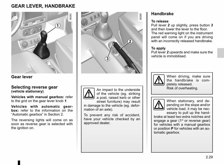
2.29
HandbrakeTo releasePull lever 2 up slightly, press button 3 and then lower the lever to the floor.The red warning light on the instrument panel will come on if you are driving with an incorrectly released handbrake.
To applyPull lever 2 upwards and make sure the vehicle is immobilised.
An impact to the underside of the vehicle (eg. striking a post, raised kerb or other street furniture) may result
in damage to the vehicle (eg. defor-mation of an axle).To prevent any risk of accident, have your vehicle checked by an approved dealer.
GEAR LEVER, HANDBRAKE
When stationary, and de-pending on the slope and/or vehicle load, it may be nec-essary to pull up the hand-
brake at least two extra notches and engage a gear (1st or reverse gear) for vehicles with a manual gearbox or position P for vehicles with an au-tomatic gearbox.
When driving, make sure the handbrake is com-pletely released.Risk of overheating.
1
2
3
Gear lever
Selecting reverse gear(vehicle stationary)Vehicles with manual gearbox: refer to the grid on the gear lever knob 1.Vehicles with automatic gear-box: refer to the information on the “Automatic gearbox” in Section 2.The reversing lights will come on as soon as reverse gear is selected with the ignition on.

2.30
4x2 (2WD) and 4x4 (4WD) mode selectorDepending on the road conditions, tur-ning selector 1 enables the following modes to be selected:– 2WD ;– AUTO ;– 4WD Lock.
TRANSMISSION: 4-wheel drive (4WD) (1/4)
“AUTO" modeTo activate this mode, turn the selec-tor 1 to the “AUTO” position.
Operating principle“AUTO” mode automatically distributes the engine torque between the front and rear axles according to the road condi-tions and the vehicle speed. This po-sition optimises roadholding. Use this mode on any type of road (dry, snow-covered, slippery, etc.) or when towing (trailer or caravan). This mode is not in-dicated on the instrument panel.
“2WD" modeTo activate this mode, turn selector 1 to
the “2WD" position. The ‘ indica-tor light will light up on the instrument panel.
Operating principleThe “2WD” mode uses the front wheels only. Use this mode on dry roads with good grip.
Remember that driving a vehicle off-road is very different to driving it on the road.To make the most of your vehicle in an off-road situation, we recom-mend that you are trained to drive a 4x4 (4WD) vehicle.The safety of both you and your passengers is your responsibility, and depends on your skill and the care you take when driving off-road.
1

2.31
TRANSMISSION: 4-wheel drive (4WD) (2/4)This problem may be resolved by chan-ging the tyres. Always use four identi-cal tyres (same brand, profile, etc.) and with similar wear.In the event of excessive wheelspin, the mechanical components may be overheating.If this happens:
– at first, the ’ warning light flashes. “4WD Lock” mode is still active, however we recommend that you stop as soon as possible to allow the system to cool down (until the warning light stops flashing);
– if the wheels still spin, the system au-tomatically switches to “2WD” mode to protect the mechanical compo-nents.
The ‘ warning light flashes. The mode cannot be changed while the light is flashing.
After one minute, the system switches to “2WD” or “AUTO” mode depending on the position of the selector.Note: if the vehicle is travelling at a speed of more than approximately 49.6 mph (80 km/h) or if it is travel-ling at a speed of between 37.2 and 49.6 mph (60 and 80 km/h) for more than one minute in «4WD Lock" mode, the system automatically switches back to "AUTO" mode. The warning light
’ goes out.
Special features of the 4-wheel drive transmissionThe vehicle may make more noise when the “AUTO" or "4WD Lock" modes are activated. This is normal. If the system detects a difference in the dimensions of the front and rear wheels (eg. un-derinflation, severe wear on an axle), the system automatically switches to "2WD" mode.
The ‘ and Ò warning lights on the instrument panel come on. Drive as soon as possible at a moderate speed to an approved dealer.
To deactivate this mode, turn selector 1
to the “AUTO” position. The ‘ indi-cator light on the instrument panel goes out.
“4WD Lock" modeTo activate this mode, turn selector 1 to the “4WD Lock” position. The selector the returns to the “AUTO” position. The
’ indicator light will light up on the instrument panel.
Operating principle“4WD Lock” mode distributes the engine torque between the front and rear axles in order to optimise the per-formance capacity of the vehicle in off-road situations. This mode should only be used in extreme driving conditions (mud, steep slopes, sand).To deactivate this mode, turn selector 1 to the “4WD Lock” position again. The indicator light on the instrument panel goes out. When the engine is switched off, the system stays in “4WD Lock” mode for one minute.

2.32
TRANSMISSION: 4-wheel drive (4WD) (3/4)Electronic stability program and traction control when driving off-road (vehicles equipped with ESC)When driving on soft ground (sand, mud, deep snow), we recommend that you deactivate the ESC function by pressing the “ ESC” switch.In this case, only individual wheel bra-king remains active. This function ap-plies the brake to any wheel that is slip-ping, allowing the engine torque to be transferred to the wheels with the most grip. This is particularly useful when crossing a bridge.All the ESC functions will be reactivated when the vehicle speed reaches ap-proximately 30 mph (50 km/h) (36 mph (60 km/h) in 4WD Lock mode), when the engine is restarted or when the “ESC” button is pressed again.
Operating faultsIf the system detects an operating fault, it automatically switches to “2WD”
mode, and the ‘ and Ò war-ning lights come on.Drive as soon as possible at a mode-rate speed to an approved dealer.For certain operating faults, the system may not be able to switch to “2WD" or "4WD Lock" mode. "AUTO" mode re-mains active.Contact an approved dealer as soon as possible.
In this case, we recommend that you stop as soon as possible to allow the system to cool down (until the warning light stops flashing).Cooling may take up to five minutes.If the system detects excessive whee-lspin on the front wheels, it adapts the engine to run in a way that reduces wheelspin.
Anti-lock braking in “LOCK” mode (vehicles equipped with ABS)When “4WD Lock" mode is active, the ABS switches to off-road mode. In this case, the wheels may lock intermit-tently to achieve better grip, thus redu-cing braking distances on soft ground. When this mode is active:– the vehicle’s manoeuvrability is limi-
ted during braking. This operating mode is therefore not recommended in very low-grip conditions (eg. ice).
– there may be some noise. This is normal, and does not indicate an operating fault.

2.33
TRANSMISSION: 4-wheel drive (4WD) (4/4)
All-wheel drive system– Irrespective of the mode selected, do not start the engine if one or more wheels are not in contact with the ground (eg. when the vehicle is on a jack or roller bench).– Do not turn the mode selector when cornering, reversing or if the wheels are spinning excessively. Only select the
“2WD”, “AUTO” or “4WD Lock” mode when the vehicle is being driven in a straight line.– Only use tyres which meet the required specifications.– “4WD Lock” mode is reserved solely for use off-road. The use of this mode in any other conditions may adversely affect the
vehicle’s manoeuvrability and damage its mechanical components.– Always ensure tyres with identical specifications are fitted to all four wheels (brand, size, structure, wear etc.). Fitting tyres
of different sizes to the front and rear wheels and/or left and right wheels may have serious consequences for the tyres, gearbox, transfer gearbox and the rear differential pinions.

2.34
ABS (anti-lock braking system)Under heavy braking, the ABS prevents the wheels from locking, allowing the stopping distance to be managed and keeping control of the vehicle. Under these circumstances, the vehicle can be steered to avoid an obstacle whilst braking. In addition, this system can increase stopping distances, particu-larly on roads with low surface grip (wet ground etc.).You will feel a pulsation through the brake pedal each time the system is activated. The ABS does not in any way improve the vehicle's physical perform-ance relating to the road surface and roadholding. It is still essential to follow the rules of good driving practice (such as driving at a safe distance from the vehicle in front etc.).
DRIVER CORRECTION DEVICES/AIDS (1/4)Depending on the vehicle, this is com-posed of:– the ABS (anti-lock braking
system);– the emergency brake assist;– electronic stability control (ESC)
with understeer control and trac-tion control.
– hill start assistance.
These functions are an ad-ditional aid in the event of critical driving conditions, enabling the vehicle behav-
iour to be adapted to suit the driving conditions.However, the functions do not take the place of the driver. They do not increase the vehicle’s limits and should not encourage you to drive more quickly. Therefore, they can under no circumstances replace the vigilance or responsibil-ity of the driver when manoeuvring the vehicle (the driver must always be ready for sudden incidents which may occur when driving).
In an emergency, apply firm and continuous pressure to the brake pedal. There is no need to pump it repeatedly. The ABS will modu-late the force applied in the braking system.
Special feature of 4-wheel drive ve-hicles In 4WD Lock mode, the system may lock the wheels briefly to optimise the braking distance on very wet ground (snow, mud, sand, etc.).

2.35
DRIVER CORRECTION DEVICES/AIDS (2/4)
Emergency brake assist with electronic brake distribution(depending on the vehicle)This system supplements the ABS and helps reduce vehicle stopping dis-tances.
Operating principleThe system is for detecting an emer-gency braking situation. In this case, the braking assistance immediately de-velops maximum power and may trig-ger ABS regulation.ABS braking is maintained as long as the brake pedal is applied.
Operating faults
– If the x warning light on the in-strument panel comes on while you are driving, the brakes will still work normally without ABS;
– If the x and D warning lights on the instrument panel come on while you are driving, there is a fault in the braking system.
In both cases, consult an approved Dealer.
Your braking systems are partially operational. However, it is dangerous to brake suddenly and
it is essential to stop immediately, as soon as traffic conditions allow. Contact an approved dealer.

2.36
DRIVER CORRECTION DEVICES/AIDS (3/4)
Electronic stability program ESC with understeer control and traction controlElectronic Stability Program ESC (depending on the vehicle)This system helps you to keep control of the vehicle in critical driving condi-tions (avoiding an obstacle, loss of grip on a bend, etc.).
Understeer controlThis system optimises the action of the ESC in the case of pronounced under-steering (loss of front axle road hold-ing).
Traction controlThis system helps to limit wheelspin of the drive wheels and to control the ve-hicle when pulling away accelerating or decelerating.
Deactivating the ESC functionIn some situations (driving on very wet ground: snow, mud, etc. or driving with snow chains fitted), the system may reduce the engine output to limit whee-lspin. If this is not required, it is possible to deactivate the function by pressing switch 1.
The warning light on the instru-ment panel comes on to warn you of this.If you deactivate this function, the traction control system will also be deactivated.With the Electronic Stability Program ESC with understeer control and trac-tion control providing additional safety, you are advised not to drive with the function disabled. Correct this as soon as possible by pressing the switch 1 again.Note: The function is automatically reactivated when the ignition is switched on, or when the speed exceeds 30 mph (50 km/h) in “AUTO” and “2WD” modes, and approximately 36 mph (60 km/h) in “4WD Lock” mode.
1

2.37
DRIVER CORRECTION DEVICES/AIDS (4/4)
Hill start assistanceDepending on the gradient of the in-cline, this system assists the driver when starting on a hill. It prevents the vehicle from rolling backwards by au-tomatically applying the brakes when the driver lifts his/her foot off the brake pedal to depress the accelerator pedal.It only operates when the gear lever is in a position other than neutral (other than N or P for automatic transmis-sions) and the vehicle is completely stationary (brake pedal depressed).The system holds the vehicle for ap-proximately 2 seconds. The brakes are then released (the vehicle will move ac-cording to the slope).
Operating principleA sensor in the steering wheel detects the direction selected by the driver.Other sensors throughout the vehicle measure the actual direction.The system compares driver input to the actual trajectory of the vehicle and corrects the trajectory if necessary by controlling the braking of certain wheels and/or engine power. In the event that the system is engaged, the indicator
light flashes on the instrument panel.
Operating faultsWhen the system detects an opera-
ting fault the warning lights Ò and
appear on the instrument panel. In this case, the Electronic Stability Program ESC with understeer control and traction control are deactivated.Please consult an authorised dealer if these warning lights remain displayed on the instrument panel after the igni-tion is switched off and on again.
The hill start assistance system cannot completely prevent the vehicle from rolling backwards in all sit-
uations (extremely steep gradients etc.).In all cases, the driver may depress the brake pedal to prevent the vehi-cle from rolling backwards.The hill start assistance function should not be used for prolonged stops: use the brake pedal.This function is not designed to im-mobilise the vehicle permanently.If necessary, use the brake pedal to stop the vehicle.The driver must remain particularly vigilant when driving on slippery or low-grip surfaces and/or on hills.Risk of serious injury.

2.38
Switching onPress switch 1 on the side showing . The warning light 6 is orange and, de-pending on the vehicle, the message “LIMIT” or the warning light ap-pears on the instrument panel, accom-panied by dashes to indicate that the speed limiter function is activated and waiting to memorise a limit speed.To store the current speed, press switch 2 (+): the limit speed will replace the dashes.The minimum stored speed is 20 mph (30 km/h).
Controls1 Main “On/Off” switch.2 Limit speed activation, storage and
increase switch (+).3 Decreasing the limit speed (-).4 Activation and recall of memorised
limit speed (R).5 Speed limiter function standby (with
limited speed memory) (O).
The speed limiter function helps you stay within the driving speed limit that you choose, known as the limit speed.
CRUISE CONTROL/SPEED LIMITER: speed limiter function (1/3)
6
1 2 3 4 5

2.39
Exceeding the limit speedIt is possible to exceed the limit speed at any time. To do this: press the accel-erator pedal firmly and fully (beyond the resistance point).While the speed is being exceeded, the programmed speed displayed on the instrument panel flashes.Then, release the accelerator: the speed limiter function will return as soon as you reach a speed lower than the stored speed.
Limited speed cannot be maintainedIf driving up or down a steep gradient, the system is unable to maintain the limit speed: the stored speed will flash on the instrument panel information dis-play to inform you of this situation.
Varying the limit speedThe limit speed may be changed by re-peatedly pressing:– switch 2 (+) to increase speed;– switch 3 (-) to reduce speed.
DrivingWhen a limited speed has been stored and this speed is not reached, driving is similar to driving a vehicle without the speed limiter function.Once you have reached the stored speed, no effort on the accelera-tor pedal will allow you to exceed the programmed speed except in an emergency (refer to information on “Exceeding the limit speed”).
CRUISE CONTROL/SPEED LIMITER: speed limiter function (2/3)
The speed limiter function is in no way linked to the brak-ing system.
2 3

2.40
CRUISE CONTROL/SPEED LIMITER: speed limiter function (3/3)
Recalling the limit speedIf a speed has been saved, it can be re-called by pressing switch 4 ((R)).
Putting the function on standbyThe speed limiter function is suspended when you press the switch 5 (O). In this case, the speed limit remains stored and, depending on the vehicle, the message "MEM” or the warning light appears on the instrument panel, accompanied by the stored speed.
Switching off the functionThe speed limiter function is deac-tivated if you press switch 1: in this case a speed is no longer stored. The orange instrument panel warning light goes out, confirming that the func-tion is stopped.
When the speed limiter is put on standby, pressing switch 2 (+) re-activates the function without taking into account the stored speed: it is the speed at which the vehicle is moving that is taken into account.
12 3 4 5
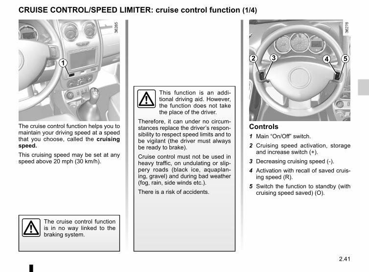
2.41
The cruise control function helps you to maintain your driving speed at a speed that you choose, called the cruising speed.This cruising speed may be set at any speed above 20 mph (30 km/h).
This function is an addi-tional driving aid. However, the function does not take the place of the driver.
Therefore, it can under no circum-stances replace the driver’s respon-sibility to respect speed limits and to be vigilant (the driver must always be ready to brake).Cruise control must not be used in heavy traffic, on undulating or slip-pery roads (black ice, aquaplan-ing, gravel) and during bad weather (fog, rain, side winds etc.).There is a risk of accidents.
The cruise control function is in no way linked to the braking system.
Controls1 Main “On/Off” switch.2 Cruising speed activation, storage
and increase switch (+).3 Decreasing cruising speed (-).4 Activation with recall of saved cruis-
ing speed (R).5 Switch the function to standby (with
cruising speed saved) (O).
CRUISE CONTROL/SPEED LIMITER: cruise control function (1/4)
1 2 3 4 5

2.42
DrivingOnce a cruising speed is stored and the cruise control function is active, you may lift your foot off the accelera-tor pedal.
Important: you are never-theless advised to keep your feet close to the pedals in order to react if neces-
sary.
Activating cruise controlAt a steady speed (above 18 mph (30 km/h approximately)) press switch 2 or (+): the function is activated and the current speed is saved.The cruising speed replaces the dashes and cruise control is confirmed by the appearance (depending on the vehi-cle) of the message “CRUISE” or the warning light and the green 7 warning light as well as the 6 warning light.
Switching onPress switch 1 side .The green warning light 6 comes on and, depending on the vehicle, the message “CRUISE” or the warning light appears on the instrument panel, accompanied by dashes to indi-cate that the cruise control function is activated and waiting to store a cruis-ing speed.
CRUISE CONTROL/SPEED LIMITER: cruise control function (2/4)
1
6
2 3
7

2.43
CRUISE CONTROL/SPEED LIMITER: cruise control function (3/4)
Exceeding the cruising speedThe cruising speed may be exceeded at any time by depressing the accelera-tor pedal. While it is being exceeded, the cruising speed flashes on the in-strument panel.Then, release the accelerator: after a few seconds, the vehicle will automati-cally return to its set cruising speed.
Cruising speed cannot be maintainedWhen driving down a steep gradient, the system is unable to maintain the cruising speed: the stored speed will flash on the instrument panel informa-tion display to inform you of this situ-ation.
Adjusting the cruising speedThe cruising speed may be changed by pressing the following repeatedly:– switch 2 (+) to increase the speed,– switch 3 (-) to decrease the speed.
The cruise control function is in no way linked to the braking system.
2 3

2.44
Switching off the functionThe cruise control function is deacti-vated if you press switch 1: in this case a speed is no longer stored. The two in-strument panel warning lights and go out to confirm that the function is deactivated.
Returning to the cruising speedIf a speed is stored, it can be recalled, once you are sure that the road con-ditions are suitable (traffic, road sur-face, weather conditions, etc.). Press switch 4 (R) if the vehicle speed is above 20 mph (30 km/h).When the stored speed is recalled, acti-vation of the cruise control is confirmed by the illumination of the warning light.NB: if the speed previously stored is much higher than the current speed, the vehicle will accelerate more rapidly to reach this threshold.
When the cruise control function is put on standby, pressing switch 2 (+) reactivates the cruise control function without taking into account the stored speed: it is the speed at which the vehicle is moving that is taken into account.
Putting the function on standbyThe function is set to standby if you:– use the switch 5 (O);– the brake pedal;– depress the clutch pedal or shift into
neutral if the vehicle has an auto-matic gearbox.
In all three cases and depending on the vehicle, the cruising speed remains stored and, depending on the vehicle, the message “MEM”or the warn-ing light appears on the instrument panel. Standby is confirmed when indicator light goes out.
CRUISE CONTROL/SPEED LIMITER: cruise control function (4/4)
Putting the cruise control on standby or switching it off does not cause a rapid reduction in speed: you
must brake by depressing the brake pedal.
2 3 4 51

2.45
AUTOMATIC GEARBOX (1/4)
Selector lever 1Display 3 on the instrument panel shows the mode and gear selected.P: ParkR: ReverseN: NeutralD: Automatic modeM: Manual mode4: zone displaying gearbox mode or
gear engaged in manual mode.
OperationWith the selection lever 1 in position P, switch on the ignition.With your foot on the brake pedal, move the lever out of position P.Only engage D or R when the vehi-cle is stopped, with your foot on the brake and the accelerator pedal re-leased.To move out of position P the brake pedal must be depressed before pressing the unlocking button .2
For safety reasons, do not switch off the ignition before the vehicle has come to a complete standstill.
1
2
3
4
Driving in automatic modePlace the lever into position D.In the majority of driving conditions, you will no longer have to use your gear lever: the gears change automatically, at the right time, to a suitable engine speed because “automatic” takes the vehicle’s load, road profile and driving style into account.
2
1
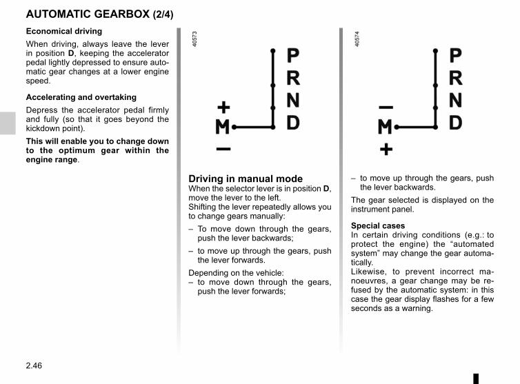
2.46
AUTOMATIC GEARBOX (2/4)
Driving in manual modeWhen the selector lever is in position D, move the lever to the left.Shifting the lever repeatedly allows you to change gears manually:– To move down through the gears,
push the lever backwards;– to move up through the gears, push
the lever forwards.Depending on the vehicle:– to move down through the gears,
push the lever forwards;
– to move up through the gears, push the lever backwards.
The gear selected is displayed on the instrument panel.
Special casesIn certain driving conditions (e.g.: to protect the engine) the “automated system” may change the gear automa-tically.Likewise, to prevent incorrect ma-noeuvres, a gear change may be re-fused by the automatic system: in this case the gear display flashes for a few seconds as a warning.
Economical drivingWhen driving, always leave the lever in position D, keeping the accelerator pedal lightly depressed to ensure auto-matic gear changes at a lower engine speed.
Accelerating and overtakingDepress the accelerator pedal firmly and fully (so that it goes beyond the kickdown point).This will enable you to change down to the optimum gear within the engine range.

2.47
AUTOMATIC GEARBOX (3/4)
Special circumstances– Depending on the vehicle, snow
position: if you are driving on slip-pery surfaces (snow, mud, etc.) press switch 5, the operating indica-tor light 6 comes on.Once these special driving con-ditions no longer apply, exit this function by pressing switch 5 again. The warning light 6 goes out.
5
– If the road contour and bends in the road do not allow you to stay in automatic mode (e.g.: in mountain-ous areas), it is recommended that you switch to manual mode.This will prevent the automatic gear-box from changing gears repeatedly when climbing, and permit engine braking on long descents.
– In cold weather, to prevent the engine from stalling, wait a few sec-onds before moving the selector lever from position P or N and en-gaging it in D or R.
– Vehicles not fitted with traction control: on a slippery surface or surface with a low level of adhesion, change to manual mode and select second gear (or even third) before starting the engine to avoid wheel-spin when accelerating.
In very cold weather, the system may prevent the gears from being shifted in manual mode until the gearbox reaches the right tempera-ture.
6

2.48
AUTOMATIC GEARBOX (4/4)
Parking the vehicleWhen the vehicle is stopped, move the lever to position P while keeping your foot on the brake pedal: the gearbox is in neutral and the drive wheels are me-chanically locked by the driveshaft.Apply the handbrake.
Operating faultsIf a vehicle with an automatic gear-box breaks down, please refer to the information on “Towing” in Section 5. When setting off, if the lever is locked in position P even though you are pressing the brake pedal, the lever can be released manually.To do this, unclip the base of the lever, simultaneously press recess 7 and the unlocking button 2.
An impact to the under-side of the vehicle while manoeuvring (e.g.: strik-ing a post, raised kerb or
other street furniture) may result in damage to the vehicle (e.g.: defor-mation of an axle).To avoid any risk of accident, have your vehicle checked by an ap-proved Dealer.
For safety reasons, do not switch off the ignition before the vehicle has come to a complete standstill.
2
7
Depending on the vehicle, unclip the base of the lever, then insert a tool (rigid rod) into the slot 8 and simulta-neously press the button 2 in order to unlock the lever.Contact an authorised dealer as soon as possible.
8
2

2.49
This function is an addi-tional aid that indicates the distance between the vehi-cle and an obstacle whilst
reversing, using sound signals.Under no circumstances should it replace the driver’s care or respon-sibility whilst reversing.The driver should always look out for sudden hazards during driving: always ensure that there are no moving obstacles (such as a child, animal, pram, bicycle, etc.) or small, narrow objects such as stones or posts in your path when manoeu-vring.
Operating principleUltrasonic sensors, fitted in the vehi-cle’s rear bumper, measure the dis-tance between the vehicle and an ob-stacle when reversing.This measurement is indicated by beeps which become more frequent the closer you come to the obstacle, until they become a continuous beep when the vehicle is approximately 40 centi-metres from the obstacle.There is a beep when reverse gear is engaged. If the beep sounds for a long time (3 seconds), this signals an oper-ating fault.NB: ensure that the ultrasonic sensors are not obscured (by dirt, mud, snow, etc.).
PARKING DISTANCE CONTROL (1/2)
An impact to the under-side of the vehicle while manoeuvring (e.g.: strik-ing a post, raised kerb or
other street furniture) may result in damage to the vehicle (e.g.: defor-mation of an axle).To avoid any risk of accident, have your vehicle checked by an ap-proved dealer.

2.50
PARKING DISTANCE CONTROL (2/2)
Deactivating the systemYou can deactivate the system by pressing switch 1.The warning light built into the switch remains lit constantly.The deactivated system can be reacti-vated by pressing the switch again.
Operating faultsWhen the system detects an operat-ing fault, there will be a three-second continuous beep as a warning. Please consult an authorised dealer.1

2.51
Note: make sure that the reversing camera is not obscured (by dirt, mud, snow, etc.).
REVERSING CAMERA (1/2)
OperationWhen using reverse gear, the camera 1 located near the tailgate sends a view of the area behind the vehicle to the multimedia display 2 together with a static guide line.This system is used with the aid of a fixed distance gauge. When the red zone is reached, use the bumper image to stop accurately.
This function is an additional aid. It cannot, therefore, under any circum-stances replace the vigilance or the responsibility of the driver.The driver should always pay attention to sudden incidents during driv-ing: always ensure that there are no moving obstacles (such as a child,
animal, pram, bicycle, etc.) or small, narrow objects such as stones or posts in your path when manoeuvring.
1
2

2.52
REVERSING CAMERA (2/2)
Static guide line 3:The static guide line 3 has coloured markers A, B and C showing the dis-tance behind the vehicle:– A (red) approximately 30 centime-
tres from the vehicle;– B (yellow) approximately 70 centi-
metres from the vehicle;– C (green) approximately 150 centi-
metres from the vehicle.
This gauge remains fixed and indicates the vehicle trajectory if the wheels are in line with the vehicle.
The screen shows a reverse image.The frames are a representation projected onto flat ground; this in-formation must not be taken into account when superimposed on a vertical object or an object on the ground.Objects which appear on the edge of the screen may be deformed.In very bright light (snow, vehicle in sunshine etc.), the camera vision may be adversely affected.
3
AB
C
3.1
Section 3: Your comfort
Air vents, air outlets . . . . . . . . . . . . . . . . . . . . . . . . . . . . . . . . . . . . . . . . . . . . . . . . . . . . . . . . . . . . . . 3.2Heating/Ventilation/Air conditioning . . . . . . . . . . . . . . . . . . . . . . . . . . . . . . . . . . . . . . . . . . . . . . . . . . 3.4Air conditioning: information and advice on use . . . . . . . . . . . . . . . . . . . . . . . . . . . . . . . . . . . . . . . . 3.7Electric windows . . . . . . . . . . . . . . . . . . . . . . . . . . . . . . . . . . . . . . . . . . . . . . . . . . . . . . . . . . . . . . . . 3.8Interior lighting . . . . . . . . . . . . . . . . . . . . . . . . . . . . . . . . . . . . . . . . . . . . . . . . . . . . . . . . . . . . . . . . . . 3.11Sun visor/grab handle . . . . . . . . . . . . . . . . . . . . . . . . . . . . . . . . . . . . . . . . . . . . . . . . . . . . . . . . . . . . 3.13Ashtrays, Cigarette lighter, Accessories socket . . . . . . . . . . . . . . . . . . . . . . . . . . . . . . . . . . . . . . . . . 3.14Rear headrests . . . . . . . . . . . . . . . . . . . . . . . . . . . . . . . . . . . . . . . . . . . . . . . . . . . . . . . . . . . . . . . . . 3.15Passenger compartment storage space and fittings . . . . . . . . . . . . . . . . . . . . . . . . . . . . . . . . . . . . . 3.16Rear bench seat . . . . . . . . . . . . . . . . . . . . . . . . . . . . . . . . . . . . . . . . . . . . . . . . . . . . . . . . . . . . . . . . 3.20Luggage compartment. . . . . . . . . . . . . . . . . . . . . . . . . . . . . . . . . . . . . . . . . . . . . . . . . . . . . . . . . . . . 3.23Transporting objects in the luggage compartment . . . . . . . . . . . . . . . . . . . . . . . . . . . . . . . . . . . . . . 3.24Transporting objects: towing, towing equipment) . . . . . . . . . . . . . . . . . . . . . . . . . . . . . . . . . . . . . . . 3.26Rear parcel shelf . . . . . . . . . . . . . . . . . . . . . . . . . . . . . . . . . . . . . . . . . . . . . . . . . . . . . . . . . . . . . . . . 3.27Roof bars . . . . . . . . . . . . . . . . . . . . . . . . . . . . . . . . . . . . . . . . . . . . . . . . . . . . . . . . . . . . . . . . . . . . . . 3.28Multimedia equipment . . . . . . . . . . . . . . . . . . . . . . . . . . . . . . . . . . . . . . . . . . . . . . . . . . . . . . . . . . . . 3.29

3.2
1 Left-hand side air vent
2 Left-hand side window demister vent
3 Windscreen demisting vents
4 Centre air vents
5 Control panel
6 Right-hand side window demister vent
7 Right-hand side air vent
8 Front passenger footwell heater outlets
9 Rear passenger footwell heater outlets (depending on the vehicle)
AIR VENTS, air outlets (1/2)
1 2 3 4 5 6 7
8 8
9 9

3.3
Centre and side air ventsAir flowTo open the air vent 10, press on the air vent (point 11) until it is open as far as required.
DirectionTo direct the air flow, swivel side air vent 10.
To remove bad odours from your ve-hicles, only use the systems designed for this purpose. Consult an approved Dealer.
AIR VENTS, air outlets (2/2)
11
10
11
10 10
Rear seats(depending on vehicle)Passenger footwell heater outlets 12.
Do not add anything to the vehicle’s ventilation circuit (for example, to remove bad odours).
There is a risk of damage or of fire.
12

3.4
HEATING, VENTILATION, AIR CONDITIONING (1/3)
2 3 41 5
ControlsThe controls will depend on the vehicle equipment level.1 Distribution of air.2 Switching air conditioning on or off.3 Adjusting the ventilation fan speed.4 De-icing/demisting of the rear screen
and, depending on the vehicle, the door mirrors and windscreen.
5 Air temperature adjuster.6 Switching passenger compartment
isolation mode/air recirculation mode on
Adjusting the air temperatureTurn control 5 to obtain the desired temperature. The further towards the red the slide is, the higher the tempera-ture will be.
Adjusting the ventilation fan speed.Turn control 3 from 0 to 4. The further to the right it is positioned, the more air is blown into the passenger compart-ment. If you want to shut off the flow of air completely and stop the system, set control 3 to 0.The system is deactivated: the ventila-tion speed for the passenger compart-ment air is zero (vehicle stationary), you can however still feel a slight flow of air when the vehicle is moving.
Leaving this control in position 0 for prolonged periods can lead to con-densation forming on the side win-dows and windscreen and problems due to the use of non-renewed air in the passenger compartment.
6
Information and advice on use: refer to information on “Air conditioning: in-formation and advice on use”.
Depending on the vehicle, in the event of setting the “Wake up every 2 hours” remote starting function, the ventilation system must be stopped before leaving the vehicle.Please see your vehicle’s multime-dia instructions.
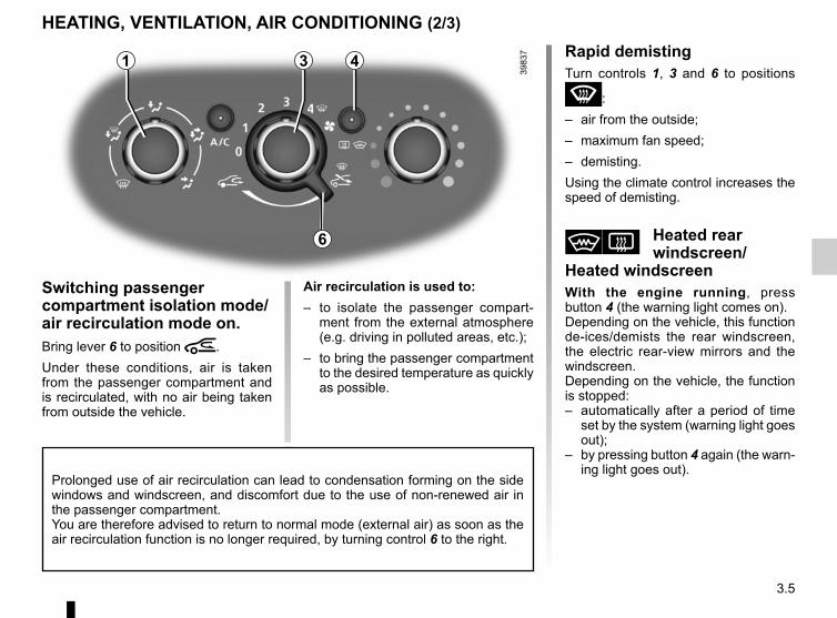
3.5
HEATING, VENTILATION, AIR CONDITIONING (2/3)
43
Switching passenger compartment isolation mode/air recirculation mode on.Bring lever 6 to position â.Under these conditions, air is taken from the passenger compartment and is recirculated, with no air being taken from outside the vehicle.
Air recirculation is used to:– to isolate the passenger compart-
ment from the external atmosphere (e.g. driving in polluted areas, etc.);
– to bring the passenger compartment to the desired temperature as quickly as possible.
Rapid demistingTurn controls 1, 3 and 6 to positions
W:– air from the outside;– maximum fan speed;– demisting.Using the climate control increases the speed of demisting.
V Heated rear windscreen/
Heated windscreenWith the engine running, press button 4 (the warning light comes on).Depending on the vehicle, this function de-ices/demists the rear windscreen, the electric rear-view mirrors and the windscreen.Depending on the vehicle, the function is stopped:– automatically after a period of time
set by the system (warning light goes out);
– by pressing button 4 again (the warn-ing light goes out).
Prolonged use of air recirculation can lead to condensation forming on the side windows and windscreen, and discomfort due to the use of non-renewed air in the passenger compartment.You are therefore advised to return to normal mode (external air) as soon as the air recirculation function is no longer required, by turning control 6 to the right.
1
6

3.6
HEATING, VENTILATION, AIR CONDITIONING (3/3)
2
Distribution of air in the passenger compartmentTurn control 1 to choose the distribution option.
J All the air flow is directed to the dashboard vents.
G The air flow is directed towards the dashboard vents and the
footwells.
F The air flow is mainly distrib-uted between the front and
rear footwells and the dashboard vents.Close the dashboard vents to direct all the air to the foot wells.
i The air flow is distributed be-tween all the air vents, the
front side window demisting air vents, the windscreen demisting vents and the footwells.
W All the air is then directed to the windscreen and front side
window demisting vents.
Switching air conditioning on or offThe air conditioning is switched on (in-dicator light illuminated) or off (indicator light extinguished) using button 2.Activation is not possible if control 3 is set to 0.
The air conditioning system is used for:– lower the temperature inside the
passenger compartment;– eliminate condensation more quickly.The air conditioning does not operate when the exterior temperature is low.
Fuel consumption increases when the air conditioning is being used (switch it off when it is not required).
1 3

3.7
AIR CONDITIONING: information and advice on use
Fuel consumptionYou will normally notice an increase in fuel consumption (especially when driving in town) when the air conditioning is operating.For vehicles fitted with air condition-ing with no automatic mode, switch off the system when it is not re-quired.Advice for reducing consumption and helping to preserve the envi-ronmentDrive with the air vents open and the windows closed.If the vehicle has been parked in the sun, open the doors for a few moments to let the hot air escape before starting the engine.
Operating faultsAs a general rule, contact your ap-proved dealer in the event of an op-erating fault.– Reduction in de-icing, demist-
ing or air conditioning per-formance.This may be caused by the pas-senger compartment filter car-tridge becoming clogged.
– No cold air is being produced.Check that the controls are set correctly and that the fuses are sound. Otherwise, switch off the system.
Do not open the refriger-ant fluid circuit. The fluid may damage eyes or skin.
Presence of water under the ve-hicle. After prolonged use of the air conditioning system, it is normal for water to be present under the vehi-cle. This is caused by condensation.
MaintenanceRefer to the Maintenance Document for your vehicle for the inspection frequency.

3.8
From the front passenger seatOperate switch 6.
ELECTRIC WINDOWS (1/3)
Manual window windersTurn the handle 1 to lower or raise the window to the desired height.
Electric windowsWith the ignition on, press the switch to lower the window to the required level;Lift the switch to raise the window to the desired height.
From the driver’s seatOperate the switches as follows:– 2 for the driver’s side;– 3 for the front passenger side;– 4 and 5 for the rear passengers.
Avoid resting any objects against a half-open window: there is a risk that the electric window winder could be damaged.
Closing windows can cause serious injury.
1
2 3
5
4
6

3.9
ELECTRIC WINDOWS (2/3)
From the rear seatsOperate switch 7.
7
8
Safety of rear occupantsThe driver can prevent operation of the rear electric windows by press-ing switch 8.
Driver’s responsibilityNever leave your vehicle with the key inside, and with a child, adult who is not self-sufficient or a pet, even for a short while. They may pose a risk to themselves or to others by starting the engine or activating equipment (such as the gear lever or electric windows). If any part of the body becomes trapped, reverse the direc-tion of the window immediately by pressing the relevant switch.Risk of serious injury.

3.10
ELECTRIC WINDOWS (3/3)
One-touch windowsWhen the vehicle is equipped with this function, the one-touch mode works in addition to the operation of the electric windows described previously.It is only fitted to the driver’s window.– Fully and briefly press down on the
relevant switch down: the window will open completely.
– Fully and briefly lift the relevant switch: the window will close com-pletely.
Pressing the switch again while the window is moving will stop its move-ment.
Special featuresIf the window detects resistance when closing (e.g.: branch of a tree, etc.) it stops and then lowers again by a few centimetres.If you use the switch while the window is moving, it stops working.
Operating faultsIn case of a fault when closing a window, the system reverts to normal mode: pull the switch concerned up to fully close the window, then hold the switch (still on the closure side) for three seconds then lower and raise the window fully to reinitialise the system.If necessary, contact an approved Dealer.
When closing the windows, ensure that no part of the body (arm, hand, etc.) is protruding from the vehicle.
Risk of serious injury. Avoid resting any objects against a half-open window: there is a risk that the electric window could be damaged.

3.11
INTERIOR LIGHTING (1/2)
Courtesy lightPressing switch 1 provides:– continuous lighting;– or temporary lighting by opening one
of the front doors, or by opening one of the four doors, depending on the vehicle. The light only goes out when the doors are correctly closed;
– no lighting.
1
Map reading lightsPressing switch 2 provides:– continuous lighting;– no lighting.
2
2

3.12
INTERIOR LIGHTING (2/2)
Automatic operation of interior lighting(depending on the vehicle)– if the doors are unlocked using
the remote control, the lighting is switched on for approximately 30 seconds.
– If a door is open (or not properly closed), the lighting is switched on for approximately 3 to 30 mi-nutes.
– if all the doors are closed, the lighting start to dim when the ig-nition is switched on.
43
Boot light 4The light 4 comes on when the boot is opened.
Glovebox light 3Light 3 comes on when the cover is opened.

3.13
Grab handle 4This offers support and can be held when the vehicle is being driven.Do not use these for getting into or out of the vehicle.
SUN VISOR/GRAB HANDLE
4
1 32
Sun visorLower the sun visor 1 or 3 over the windscreen or unclip it and turn it over the side window.
Courtesy mirrors 2Depending on the vehicle, the sun visors are fitted with a courtesy mirror.

3.14
Cigarette lighter 3With the ignition on, push in the ciga-rette lighter 3.It will spring back with a click when it is ready. Pull it out to use. After use, re-place it without pushing it all the way in.
Accessories sockets 3 and 5The sockets are provided for con-necting accessories approved by our Technical Department.
ASHTRAYS/CIGAR LIGHTER/ACCESSORIES SOCKET
AshtrayIt can be housed in either position 1 or 4. Lift the cover 2 to open.Remove the ashtray to empty it.
If your vehicle is not fitted with a cigar lighter and an ashtray, these can be obtained from an approved Dealer.
Connect accessories with a maximum power of 120 Watts (12 V) only.When several accessory
sockets are used at the same time, the total power of the connected accessories must not exceed 180 watts.Fire hazard.
12
4
3
5

3.15
REAR HEADRESTS
The headrest is a safety component. Ensure that it is fitted and in the correct po-sition: the top of your head
should be in line with the top of the headrest.
C
1
To remove the headrests A or BRaise the headrest as far as it will go, then press button 1 and remove the headrest.
To adjust the height of the headrest A(depending on vehicle)Press the button 1 and simultaneously slide the headrest to the desired height.
To reinstall the headrests A or BInsert the rods in the holes, press button 1, lower the headrest and check that it is securely in place.
Position for using the headrest B(depending on vehicle)Lift the headrest to maximum height, then lower it until it locks.
Storage position for the headrest B(depending on vehicle)Press the button 1 and lower the head-rest completely.When the headrest is set at the lowest position (position C), this is for storage only: it should not be in this position when a seat is occupied.
B AAB
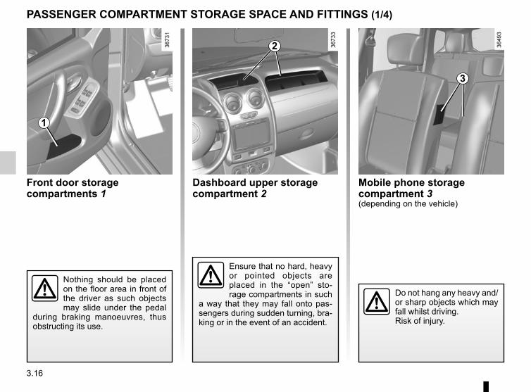
3.16
Dashboard upper storage compartment 2
PASSENGER COMPARTMENT STORAGE SPACE AND FITTINGS (1/4)
Front door storage compartments 1
Ensure that no hard, heavy or pointed objects are placed in the “open” sto-rage compartments in such
a way that they may fall onto pas-sengers during sudden turning, bra-king or in the event of an accident.
Nothing should be placed on the floor area in front of the driver as such objects may slide under the pedal
during braking manoeuvres, thus obstructing its use.
1
2
Mobile phone storage compartment 3(depending on the vehicle)
Do not hang any heavy and/or sharp objects which may fall whilst driving.Risk of injury.
3

3.17
Centre console storage compartment 5(or location of the 4x2 (2WD) and 4X4 (4WD) mode selector)
Locations for cup holder or ashtray 6.
PASSENGER COMPARTMENT STORAGE SPACE AND FITTINGS (2/4)
Centre console storage compartment 4(or radio location)
When cornering, accelera-ting or braking, ensure that the cup does not spill.There is a risk of burning if
hot liquid escapes.
Ensure that no hard, heavy or pointed objects are placed in the “open” sto-rage compartments in such
a way that they may fall onto pas-sengers during sudden turning, bra-king or in the event of an accident.
64
5

3.18
This glove box can be used to store A4 format documents.Inside the cover, a section 8 has been provided for pens, maps, etc.
PASSENGER COMPARTMENT STORAGE SPACE AND FITTINGS (3/4)
Passenger side glove boxPull handle 7 to open it.
Precautions during useCover A in the bottom of the glove box protects a socket reserved ex-clusively for operations by the ap-proved dealer networkYou should therefore avoid keeping liquids in this compartment (there is a risk of liquid leaking and getting into this socket).
Nothing should be placed on the floor area in front of the driver as such objects may slide under the pedal during braking manoeuvres, thus obs-tructing its use.
A
7
8

3.19
10
9
PASSENGER COMPARTMENT STORAGE SPACE AND FITTINGS (4/4)
Front seat storage pockets 9
Ensure that no hard, heavy or pointed objects are placed in the “open” sto-rage compartments in such
a way that they may fall onto pas-sengers during sudden turning, bra-king or in the event of an accident.
Bottle holders 10It can hold a 1.5 litre bottle.
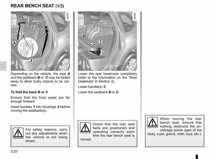
3.20
Lower the rear headrests completely (refer to the information on the “Rear headrests” in Section 3).Lower handle(s) 3.Lower the seatback B or C.
Depending on the vehicle, the seat A and the seatback B or C may be folded away to allow bulky objects to be car-ried.
To fold the back B or CEnsure that the front seats are far enough forward.Insert buckles 1 into housings 2 before moving the seatback(s).
For safety reasons, carry out any adjustments when the vehicle is not being driven.
REAR BENCH SEAT (1/3)
When moving the rear bench seat, ensure that nothing obstructs the an-chorage points (part of the
body, a pet, gravel, cloth, toys, etc.).
B
C 3
1
2
A
Check that the rear seat belts are positioned and operating correctly each time the rear bench seat is
moved.

3.21
REAR BENCH SEAT (2/3)
When refitting the seat-back, make sure it is cor-rectly locked in place.If seat covers are fitted,
make sure these do not prevent the seatback latch from locking in.Make sure that the seat belts are positioned correctly.Reposition the headrests.
Check that the rear seat belts are positioned and operating correctly each time the rear bench seat is
moved.
For safety reasons, carry out any adjustments when the vehicle is not being driven.
To reposition the seat back B or CLift the seatback(s).Check the seatbacks are correctly locked in position.Refit the rear headrests (refer to the information on the “Rear headrests” in Section 3).
To fold away the seat baseTilt the seat base A against the front seats.
To fold the back B or CPress the tab and lift the headrest to remove it.Proceed as described above.
A
B
C
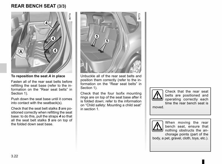
3.22
REAR BENCH SEAT (3/3)
To reposition the seat A in placeFasten all of the rear seat belts before refitting the seat base (refer to the in-formation on the “Rear seat belts” in Section 1).Push down the seat base until it comes into contact with the seatback(s).Check that the seat belt stalks 5 are po-sitioned correctly when refitting the seat base: to do this, pull the straps 4 so that all the seat belt stalks 5 are on top of the folded down seat base.
Unbuckle all of the rear seat belts and position them correctly (refer to the in-formation on the “Rear seat belts” in Section 1).Check that the four Isofix mounting rings are on top of the seat base after it is folded down; refer to the information on “Child safety: Mounting a child seat” in section 1.
When moving the rear bench seat, ensure that nothing obstructs the an-chorage points (part of the
body, a pet, gravel, cloth, toys, etc.).
Check that the rear seat belts are positioned and operating correctly each time the rear bench seat is
moved.
55
4
4
4
A
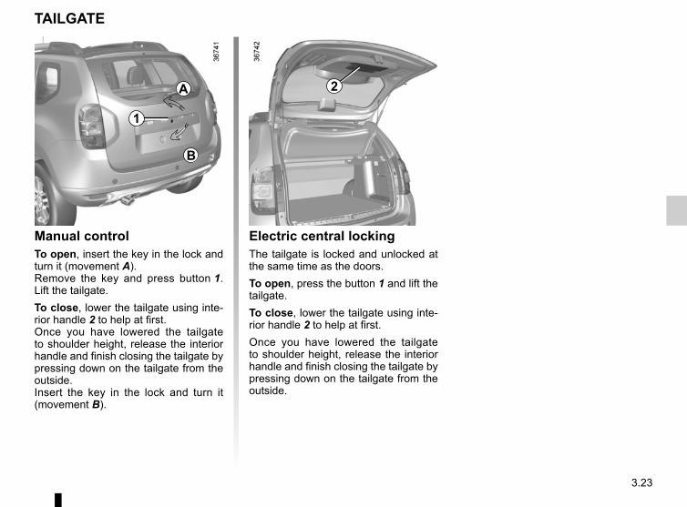
3.23
TAILGATE
Manual control To open, insert the key in the lock and turn it (movement A).Remove the key and press button 1. Lift the tailgate.To close, lower the tailgate using inte-rior handle 2 to help at first.Once you have lowered the tailgate to shoulder height, release the interior handle and finish closing the tailgate by pressing down on the tailgate from the outside.Insert the key in the lock and turn it (movement B).
Electric central locking The tailgate is locked and unlocked at the same time as the doors.To open, press the button 1 and lift the tailgate.To close, lower the tailgate using inte-rior handle 2 to help at first.Once you have lowered the tailgate to shoulder height, release the interior handle and finish closing the tailgate by pressing down on the tailgate from the outside.
1
2A
B

3.24
TRANSPORTING OBJECTS IN THE BOOT (1/2)
Always position the objects trans-ported so that the largest surface is against:
– the rear bench seatbacks, for normal loads (eg: A);
– the front seats when the rear seats are folded down. Refer to the infor-mation on the “Rear bench seat: functions” in this section (eg: B).
Always position the heaviest items di-rectly on the floor.Always place objects being trans-ported so that the heaviest items are resting against the back of the rear bench seat.
Fasten the rear seat belts, even if the seats are not oc-cupied.
A
B

3.25
TRANSPORTING OBJECTS IN THE BOOT (2/2)
Always position the heavi-est items directly on the floor. Use the lashing points 1 on the boot floor, if
these are fitted to the vehicle. The luggage should be loaded in such a way that no items will be thrown for-ward and strike the occupants if the driver has to brake suddenly.
1 1 1 1
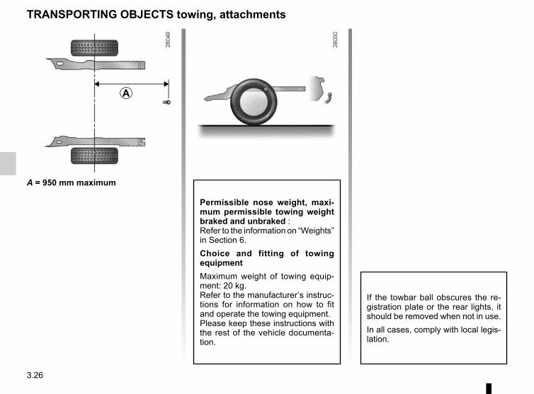
3.26
TRANSPORTING OBJECTS towing, attachments
Permissible nose weight, maxi-mum permissible towing weight braked and unbraked :Refer to the information on “Weights” in Section 6.Choice and fitting of towing equipmentMaximum weight of towing equip-ment: 20 kg.Refer to the manufacturer’s instruc-tions for information on how to fit and operate the towing equipment.Please keep these instructions with the rest of the vehicle documenta-tion.
A = 950 mm maximum
If the towbar ball obscures the re-gistration plate or the rear lights, it should be removed when not in use. In all cases, comply with local legis-lation.
A
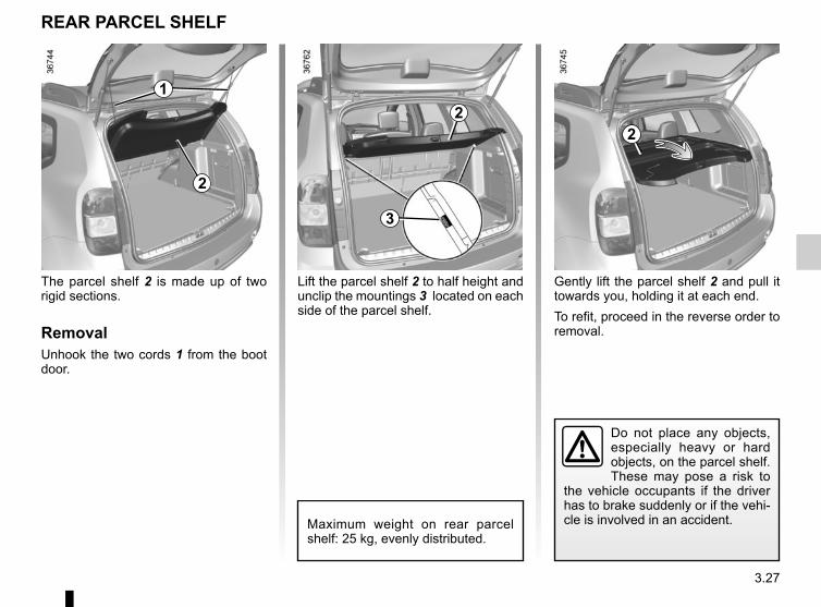
3.27
Lift the parcel shelf 2 to half height and unclip the mountings 3 located on each side of the parcel shelf.
REAR PARCEL SHELF
Do not place any objects, especially heavy or hard objects, on the parcel shelf. These may pose a risk to
the vehicle occupants if the driver has to brake suddenly or if the vehi-cle is involved in an accident.Maximum weight on rear parcel
shelf: 25 kg, evenly distributed.
1
2
The parcel shelf 2 is made up of two rigid sections.
RemovalUnhook the two cords 1 from the boot door.
2
3
Gently lift the parcel shelf 2 and pull it towards you, holding it at each end.To refit, proceed in the reverse order to removal.
2

3.28
LONGITUDINAL ROOF BARS
For information on the range of equipment adapted to your ve-hicle, we advise you to consult an approved Dealer. Refer to the manufacturer’s instructions for in-formation on how to fit and operate the equipment.Please keep these instructions with the rest of the vehicle documenta-tion.Maximum permissible load on roof rack: refer to the information on “Weights” in Section 6.
1
If fitted on the vehicle, you can trans-port luggage or additional equipment (bike racks, ski racks, etc):– on a roof rack;– on transverse roof bars which must
in turn be attached to roof bars fitted lengthways 1;
– directly onto the longitudinal roof bars.
It is forbidden to fit longitudinal roof bars on vehicles which are not origi-nally equipped with them.
2
If fitted to the vehicle, you can use the mounting holes 2 of the longitudinal bars to:– use luggage restraint systems
(straps, cords, etc.);– attach additional items without using
the transverse roof bars.

3.29
MULTIMEDIA EQUIPMENT
The presence and location of this equipment depends on the vehicle’s multimedia equipment.1 Radio or navigation system2 Steering column control;3 Microphone.
Please refer to the instruction manual for details of how it works.
Using the telephoneWe remind you of the need to conform to the legislation in force concerning the use
of such equipment.
Hands-free telephone integrated controlOn equipped vehicles, use micro-phone 3 and steering column control 2.
1
2
3

3.30

4.1
Section 4: Maintenance
Bonnet . . . . . . . . . . . . . . . . . . . . . . . . . . . . . . . . . . . . . . . . . . . . . . . . . . . . . . . . . . . . . . . . . . . . . . . . 4.2Engine oil level: general information . . . . . . . . . . . . . . . . . . . . . . . . . . . . . . . . . . . . . . . . . . . . . . . . . 4.4Engine oil level: topping up/filling . . . . . . . . . . . . . . . . . . . . . . . . . . . . . . . . . . . . . . . . . . . . . . . . . . . 4.5Levels: . . . . . . . . . . . . . . . . . . . . . . . . . . . . . . . . . . . . . . . . . . . . . . . . . . . . . . . . . . . . . . . . . . . . . . . 4.8
Brake fluid level . . . . . . . . . . . . . . . . . . . . . . . . . . . . . . . . . . . . . . . . . . . . . . . . . . . . . . . . . . . 4.8Engine coolant . . . . . . . . . . . . . . . . . . . . . . . . . . . . . . . . . . . . . . . . . . . . . . . . . . . . . . . . . . . . 4.9Power-assisted steering pump . . . . . . . . . . . . . . . . . . . . . . . . . . . . . . . . . . . . . . . . . . . . . . . . 4.10Windscreen washer reservoir . . . . . . . . . . . . . . . . . . . . . . . . . . . . . . . . . . . . . . . . . . . . . . . . . 4.10
Filters . . . . . . . . . . . . . . . . . . . . . . . . . . . . . . . . . . . . . . . . . . . . . . . . . . . . . . . . . . . . . . . . . . . . . . . . . 4.11Tyre pressure. . . . . . . . . . . . . . . . . . . . . . . . . . . . . . . . . . . . . . . . . . . . . . . . . . . . . . . . . . . . . . . . . . . 4.12Battery . . . . . . . . . . . . . . . . . . . . . . . . . . . . . . . . . . . . . . . . . . . . . . . . . . . . . . . . . . . . . . . . . . . . . . . . 4.14Bodywork maintenance . . . . . . . . . . . . . . . . . . . . . . . . . . . . . . . . . . . . . . . . . . . . . . . . . . . . . . . . . . . 4.16Interior trim maintenance . . . . . . . . . . . . . . . . . . . . . . . . . . . . . . . . . . . . . . . . . . . . . . . . . . . . . . . . . . 4.18

4.2
BONNET (1/2)
To open the bonnet, pull handle 1.
Unlocking the bonnet catchTo unlock, raise the bonnet slightly and release hook 2 by pushing tab 4 to the left.
Opening the bonnetLift the bonnet and guide it upwards; it is held by strut 3.
Closing the bonnetCheck that nothing has been left in the engine compartment.To close the bonnet again, hold the bonnet in the middle and lower it to 30 cm above the closed position, then release it. It will latch automatically under its own weight.
The engine may be hot during operations in close proximity. In addition, the engine cooling fan may
come on at any moment.Risk of injury.
Do not press down on the bonnet: there is a risk that the bonnet may accidentally close.
1
When working in the engine compartment, ensure that the windscreen wiper stalk is in the park position.
Risk of injury.
2
3
4 Deactivate the Stop and Start function for any opera-tion performed in the engine compartment.
4.3
Make sure nothing is left in the engine compartment (cloth, tools, etc.).Otherwise, this may lead to
engine damage or cause a fire.
In the event of even a slight impact involving the radia-tor grille or bonnet, have the bonnet lock checked by
an approved Dealer as soon as pos-sible.
Ensure that the bonnet is prop-erly locked. Check that nothing is preventing the catch from locking (gravel, cloth, etc.).
BONNET (2/2)
Never activate the remote engine start-up function or its programming before opening the bonnet or when
it is open.Risk of burns or serious injury.

4.4
ENGINE OIL LEVEL: general information
Reading the oil levelThe oil level should be read with the ve-hicle on level ground, after the engine has been switched off for some time.The dipstick must be used to read the exact oil level and make sure that the maximum level has not been exceeded (risk of engine damage). Refer to the following pages.
C
AB
A
B
Exceeding the maximum engine oil level Under no circumstances must the maximum fill
level B be exceeded: risk of damage to the engine and catalytic con-verter.If the oil level exceeds the maximum level, do not start your vehicle. Contact an authorised dealer.
It is normal for an engine to use oil for lubrication and cooling of moving parts and it is normal to top up the level be-tween oil changes.However, contact your approved Dealer if more than 0.5 litres is being consumed every 600 miles (1,000 km) after the running in period.Oil change frequency: check the oil level from time to time and certainly before any long journey to avoid the risk of damaging your engine.
Consult your approved dealer at once if you notice an abnormal or repeated drop in any of the fluid levels.
In order to prevent splashback, it is recommended that a funnel be used when topping up/filling with oil.
– remove the dipstick and wipe with a clean, lint-free cloth;
– push the dipstick in as far as it will go (for vehicles equipped with a cap-type dipstick C, screw the cap in as far as it will go);
– take out the dipstick again;– read the level: it should never fall
below minimum mark A or exceed maximum mark B.
Once the operation has been comple-ted, ensure that the dipstick is pushed in as far as it will go or that the “cap-type dipstick” is completely screwed in.
Deactivate the Stop and Start function for any opera-tion performed in the engine compartment.

4.5
ENGINE OIL LEVEL: topping up, filling (1/3)
Topping up/fillingThe vehicle must be parked on level ground and the engine should be cold (for instance, before the engine is started up for the first time in the day).
– Unscrew cap 1;– top up the level (as a guide, the ca-
pacity between the minimum and maximum reading on dipstick 2 is between 1.5 and 2 litres, depending on the engine);
– wait approximately 10 minutes to allow the oil to flow into the engine;
– check the level using the dipstick 2 (as described above).
Once the operation has been com-pleted, ensure that the dipstick is pushed in as far as it will go or that the “cap-type dipstick” is completely screwed in.
Do not exceed the MAX level and do not forget to refit dipstick 2 and cap 1.
1
2
The engine may be hot during operations in close proximity. In addition, the engine cooling fan may
come on at any moment.Risk of injury.
1
2
Exceeding the maximum engine oil level Under no circumstances must the maximum fill level
be exceeded: risk of damage to the engine and catalytic converter.If the oil level exceeds the maximum level, do not start your vehicle. Contact an authorised dealer.
1
2

4.6
ENGINE OIL LEVEL: topping up, filling (2/3)
Filling: take care when topping up the oil that no oil drips onto engine components - risk of fire.
Remember to refit the cap securely as there is a risk of fire if oil splashes onto hot engine components.
If there is an abnormal or repeated drop in the fluid level, please consult an authorised dealer.
Engine oil change: if you are changing the oil when the engine is hot, be careful not to scald yourself if the
oil overflows.
1
2
1
1
2
In order to prevent splashback, it is recommended that a funnel be used when topping up/filling with oil.
1
2

4.7
ENGINE OIL LEVEL: topping up, filling (3/3)
Never run the engine in an enclosed space as exhaust gases are poisonous.
Resetting the alert after an oil change(depending on the vehicle)If you change the oil yourself, you will need to reset the oil change warning.To do this, after switching on the igni-tion, for ten seconds you must:– Depress the accelerator pedal fully,– with your foot on the accelerator, de-
press the brake pedal three times in succession.
Reinitialisation is complete when the
# indicator light goes out. If this is not the case, repeat the operation.Special case: if you change the oil before the oil change interval exceeded warning is displayed, it will also be nec-essary to reset the display. In this case,
the # warning light comes on for approximately 5 seconds to confirm the reset.
The engine may be hot during operations in close proximity. In addition, the engine cooling fan may
come on at any moment.Risk of injury.
Exceeding the maximum engine oil level Under no circumstances must the maximum fill level
be exceeded: risk of damage to the engine and catalytic converter.If the oil level exceeds the maximum level, do not start your vehicle. Contact an authorised dealer.
Deactivate the Stop and Start function for any opera-tion performed in the engine compartment.
Oil changeService interval: refer to the Maintenance Document for your vehi-cle.
Oil change capacityPlease refer to the maintenance docu-ment for your vehicle, or contact an au-thorised dealer. Always check the engine oil level using the dipstick, as explained previously (it should never fall below the minimum level, or be over the maximum level on the dipstick).
Engine oil gradeRefer to the Maintenance Document for your vehicle.
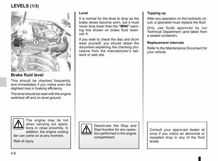
4.8
LEVELS (1/3)
Brake fluid levelThis should be checked frequently, and immediately if you notice even the slightest loss in braking efficiency.The level should be read with the engine switched off and on level ground.
LevelIt is normal for the level to drop as the brake shoes become worn, but it must never drop lower than the “MINI” warn-ing line shown on brake fluid reser-voir 1.If you wish to check the disc and drum wear yourself, you should obtain the document explaining the checking pro-cedure from the manufacturer’s net-work or web site.
Topping upAfter any operation on the hydraulic cir-cuit, a specialist must replace the fluid.Only use fluids approved by our Technical Department (and taken from a sealed container).
Replacement intervalsRefer to the Maintenance Document for your vehicle.
The engine may be hot when carrying out opera-tions in close proximity. In addition, the engine cooling
fan can come on at any moment.Risk of injury.
Consult your approved dealer at once if you notice an abnormal or repeated drop in any of the fluid levels.
1
Deactivate the Stop and Start function for any opera-tion performed in the engine compartment.

4.9
LEVELS (2/3)Coolant level checking frequencyCheck the coolant level regularly (very severe damage is likely to be caused to the engine if it runs out of coolant).If the level needs to be topped up, only use products approved by our Technical Department which ensure:– protection against freezing;– anticorrosion protection of the cool-
ing system.
Replacement intervalsRefer to the Maintenance Document for your vehicle.
No operations should be carried out on the cooling circuit when the engine is hot.
Risk of burns.
Consult your approved dealer at once if you notice an abnormal or repeated drop in any of the fluid levels.
The engine may be hot when carrying out opera-tions in close proximity. In addition, the engine cooling
fan can come on at any moment.Risk of injury.
Windscreen washer reservoirFilling: Remove cap 3, fill until you can see the fluid, then refit the cap.This reservoir supplies the front and rear screen washers.Liquid: Special windscreen washer fluid (anti-freeze product in winter).Jets: to adjust the angle of the jets, pivot the little ball using a pin.Use products approved by the Technical Department.
CoolantWith the engine switched off and on level ground, the level when cold must be between the MINI and MAXI marks on reservoir 2.Top this level up when cold before it reaches the MINI mark.
2
3

4.10
LEVELS (3/3)
Power-assisted steering fluid reservoir 4 or 5Level: for a correct level when cold, with the engine switched off and on level ground, it must be visible between the “MINI” and “MAXI” marks on reser-voir 4 or 5.For maintenance operations on the power-assisted steering, contact an ap-proved dealer.
The engine may be hot when carrying out opera-tions in close proximity. In addition, the engine cooling
fan can come on at any moment.Risk of injury.
Consult an approved dealer at once if you notice an abnormal or re-peated drop in any of the fluid levels.
If you feel any variation in the ef-fectiveness of the power-assisted steering, consult an approved dealer.
5
4
Deactivate the Stop and Start function for any opera-tion performed in the engine compartment.
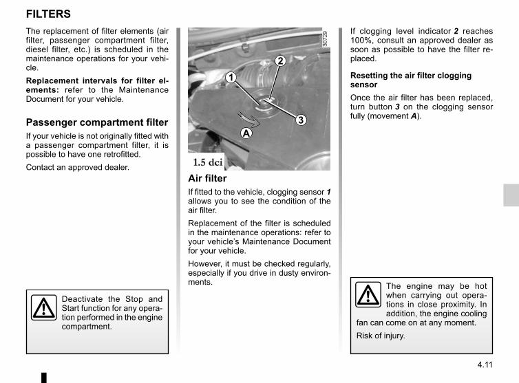
4.11
FILTERSThe replacement of filter elements (air filter, passenger compartment filter, diesel filter, etc.) is scheduled in the maintenance operations for your vehi-cle.Replacement intervals for filter el-ements: refer to the Maintenance Document for your vehicle.
Passenger compartment filterIf your vehicle is not originally fitted with a passenger compartment filter, it is possible to have one retrofitted.Contact an approved dealer.
The engine may be hot when carrying out opera-tions in close proximity. In addition, the engine cooling
fan can come on at any moment.Risk of injury.
Air filterIf fitted to the vehicle, clogging sensor 1 allows you to see the condition of the air filter.Replacement of the filter is scheduled in the maintenance operations: refer to your vehicle’s Maintenance Document for your vehicle.However, it must be checked regularly, especially if you drive in dusty environ-ments.
If clogging level indicator 2 reaches 100%, consult an approved dealer as soon as possible to have the filter re-placed.
Resetting the air filter clogging sensorOnce the air filter has been replaced, turn button 3 on the clogging sensor fully (movement A).
12
3A
Deactivate the Stop and Start function for any opera-tion performed in the engine compartment.

4.12
TYRE PRESSURE (1/2)
The presence and location of the infor-mation on the label depends on the ve-hicle.B: dimension of the tyres fitted to the vehicle.C: tyre pressures for the front wheels (non-motorway).D: tyre pressures for the rear wheels (non-motorway).E: tyre pressures for the front wheels (motorway).F: tyre pressures for the rear wheels (motorway driving).
A
Label ATo read it, open the driver’s door. Tyre pressures should be checked when the tyres are cold.If the tyre pressures cannot be checked when the tyres are cold, increase the pressures from 0.2 to 0.3 bar (or 3 PSI). Never deflate a hot tyre.
G: tyre pressure for the emergency spare wheel.H: intended driving speed.I: tyre pressures for the front wheels.J: tyre pressures for the rear wheels.
4.13
TYRE PRESSURES (2/2)Special note concerning fully laden vehicles (Maximum Permissible All-Up Weight) and towing a trailer: the maxi-mum speed must be limited to 60 mph (100 kph) and the tyre pressure in-creased by 0.2 bar.Please refer to the information on “Weights” in Section 6.Tyre safety and use of snow chains: Refer to the information on “Tyres” in Section 5 for the servicing conditions and, depending on the version, the use of chains.
Vehicle fitted with a tyre pressure loss warning system If under-inflated (puncture, low pres-
sure, etc.), the warning light on the instrument panel comes on. See “Tyre pressure loss warning” paragraph in chapter 2. For your safety, please re-
spect the speed limit.When they need to be re-placed, only tyres of the
same make, size, type and profile should be used on a single axle.They must: either have a load ca-pacity and speed rating at least equal to those of the original tyres, or conform to those recom-mended by an authorised dealer.Failure to heed these instructions could endanger your safety and affect your vehicle’s roadworthi-ness.Risk of loss of control of the ve-hicle.
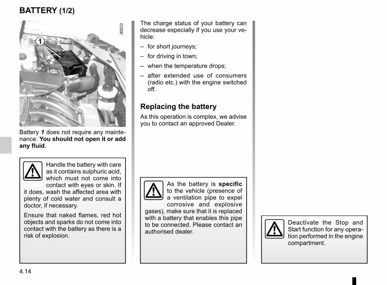
4.14
BATTERY (1/2)
Battery 1 does not require any mainte-nance. You should not open it or add any fluid.
Handle the battery with care as it contains sulphuric acid, which must not come into contact with eyes or skin. If
it does, wash the affected area with plenty of cold water and consult a doctor, if necessary.Ensure that naked flames, red hot objects and sparks do not come into contact with the battery as there is a risk of explosion.
1
The charge status of your battery can decrease especially if you use your ve-hicle:– for short journeys;– for driving in town;– when the temperature drops;– after extended use of consumers
(radio etc.) with the engine switched off.
Replacing the batteryAs this operation is complex, we advise you to contact an approved Dealer.
As the battery is specific to the vehicle (presence of a ventilation pipe to expel corrosive and explosive
gases), make sure that it is replaced with a battery that enables this pipe to be connected. Please contact an authorised dealer.
Deactivate the Stop and Start function for any opera-tion performed in the engine compartment.

4.15
BATTERY (2/2)
Label AObserve the indications on the battery:– 2 Naked flames and smoking forbid-
den;– 3 Wear eye protection;– 4 Keep away from children;– 5 Explosive substances;– 6 Refer to the handbook;– 7 Corrosive substances.
The engine may be hot during operations in close proximity. In addition, the engine cooling fan may
start at any moment.Risk of injury.
A 2 3 4
567
A

4.16
BODYWORK MAINTENANCE (1/2)
You shouldWash your car frequently, with the engine off, with cleaning products rec-ommended by the manufacturer (never use abrasive products). Rinse thor-oughly beforehand with a jet:– spots of tree resin and industrial
grime;– mud in the wheel arches and under-
neath the body which forms damp patches;
– bird droppings, which cause a chemical reaction with the paint that rapidly discolours paintwork and may even cause the paint to peel off;
wash the vehicle immediately to remove these marks since it is im-possible to remove them by polish-ing;
– salt, particularly in the wheel arches and underneath the body after driv-ing in areas where the roads have been gritted.
Remove any plant matter (resin, leaves, etc.) from the vehicle regularly.
What you should not doDo not degrease or clean mechani-cal components (e.g. the engine com-partment), underneath the body, parts with hinges (e.g. inside the doors) and painted plastic external fittings (e.g. bumpers) using high-pressure clean-ing equipment or by spraying on prod-ucts not approved by our Technical Department. Doing this could give rise to corrosion or operational faults.Wash the vehicle in bright sunlight or freezing temperatures.Do not scrape off mud or dirt without pre-wetting.Allow dirt to accumulate on the exterior.Allow rust to form following minor im-pacts.Do not use solvents not approved by our Technical Department to remove stains as this could damage the paint-work.Do not drive in snow or muddy condi-tions without washing the vehicle, par-ticularly under the wheel arches and body.
A well-maintained vehicle will last longer. It is therefore recommended to maintain the exterior of the vehicle reg-ularly.Your vehicle has been treated with very effective anti-corrosion products. It is nevertheless subject to various outside influences.
Corrosive agents in the atmosphere– atmospheric pollution (built-up and
industrial areas),– saline atmospheres (near the sea,
particularly in hot weather),– seasonal and damp weather condi-
tions (e.g. road salt in winter, water from road cleaners, etc.).
Minor impacts
Abrasive actionDust and sand in the air, mud, road grit thrown up by other vehicles, etc.You should take a number of minor pre-cautions in order to safeguard your ve-hicle against such risks.

4.17
Respect local regulations about wash-ing vehicles (e.g. do not wash your ve-hicle on a public highway).Observe the vehicle stopping distances when driving on gravelled surfaces to prevent paint damage.Repair, or have repaired quickly, areas where the paint has been damaged, to prevent corrosion spreading.Remember to visit the body shop pe-riodically in order to maintain your anti-corrosion warranty. Refer to the Maintenance Document.If it is necessary to clean mechani-cal components, hinges, etc., spray them with products approved by our Technical Department to protect them after they have been cleaned.
BODYWORK MAINTENANCE (2/2)
We have selected special products to care for your vehicle and you can obtain these from the manufactur-er’s accessory outlets.
Using a roller type car washReturn the windscreen wiper stalk to the Park position (refer to the informa-tion on the “Windscreen washer, wiper” in Section 1). Check the mounting of external accessories, additional lights and mirrors, and ensure that the wiper blades are secured with adhesive tape.Remove the radio aerial mast if your vehicle is fitted with this equipment. Remember to remove the tape and refit the antenna after washing.
Cleaning the headlightsAs the headlights are made of plastic “glass”, use a soft cloth or cotton wool to clean them. If this does not clean them properly, moisten the cloth with soapy water, then wipe clean with a soft damp cloth or cotton wool.Finally, carefully dry off with a soft dry cloth.Cleaning products containing alco-hol must not be used.
Vehicles with a matte paint finishThis type of paint requires certain pre-cautions.
Do not do the following– use wax-based products (polishing);– rub hard;– wash the vehicle in a roller-type car
wash;– wash the vehicle using a high-pres-
sure device;– attach stickers to the paintwork (risk
of leaving marks).
You should do the followingWash the vehicle by hand using plenty of water, using a soft cloth or a gentle sponge.
4.18
Glass instrument panel(e.g.: instrument panel, clock, exterior temperature display, radio display, mul-timedia or multifunction display etc.)Use a soft cloth (or cotton wool).If this does not clean them properly, use a soft cloth (or cotton wool) slightly moistened with soapy water and then wipe clean with another soft damp cloth or cotton wool.Finally, carefully dry off with a soft dry cloth.Do not use products containing alco-hol and/or spray fluids on the area.
Seat beltsThese must be kept clean.Use products selected by our Technical Department (Approved outlets) or warm, soapy water and a sponge and wipe with a dry cloth.Detergents or dyes must not be used under any circumstances.
INTERIOR TRIM MAINTENANCE (1/2)
Textiles (seats, door trim, etc)Vacuum-clean the textiles regularly.
Liquid stainUse soapy water.Dab lightly (never rub) with a soft cloth, rinse and remove the excess.
Solid or pasty stainCarefully remove the excess solid or pasty material immediately with a spatula (working from the edges to the centre to avoid spreading the stain).Clean as for a liquid stain.
Special instructions for sweets or chewing gumPut an ice cube on the stain to solidify it, then proceed as for a solid stain.
A well-maintained vehicle will last longer. It is therefore recommended to maintain the interior of the vehicle regu-larly.A stain should always be dealt with swiftly.Whatever type of stain is on the trim, use cold (or warm) soapy water with natural soap.Detergents (washing-up liquid, pow-dered products, alcohol-based prod-ucts) should not be used.Use a soft cloth.Rinse and soak up the excess.
For further recommendations for maintaining the interior, and/or for any unsatisfactory results, please see an authorised dealer.

4.19
You are strongly recom-mended not to use high-pressure or spray cleaning equipment inside the pas-
senger compartment: use of such equipment could impair the correct functioning of the electrical or elec-tronic components in the vehicle, or have other detrimental effects.
INTERIOR TRIM MAINTENANCE (2/2)
You should not:You are strongly advised not to po-sition objects such as deodorants, scents, etc. near air vents, as this could damage your dashboard trim.
Removal/replacing removable equipment originally fitted in the vehicleIf you need to remove equipment in order to clean the passenger com-partment (for example, mats), always ensure that they are correctly refitted and are the right way around (the driv-er’s mat should be fitted on the driver’s side, etc.) and fit them with the compo-nents supplied with the equipment (for example, the driver mat should always be fixed using the pre-fitted mounting components).With the vehicle stationary, always ensure that nothing will impede driving (anything obstructing the pedals, heel wedged by the mat etc.).

4.20

5.1
Section 5: Practical advice
Tools . . . . . . . . . . . . . . . . . . . . . . . . . . . . . . . . . . . . . . . . . . . . . . . . . . . . . . . . . . . . . . . . . . . . . . . . . 5.2Puncture . . . . . . . . . . . . . . . . . . . . . . . . . . . . . . . . . . . . . . . . . . . . . . . . . . . . . . . . . . . . . . . . . . . . . . 5.3Tyre inflation kit . . . . . . . . . . . . . . . . . . . . . . . . . . . . . . . . . . . . . . . . . . . . . . . . . . . . . . . . . . . . . . . . . 5.5Wheel trim/Wheels . . . . . . . . . . . . . . . . . . . . . . . . . . . . . . . . . . . . . . . . . . . . . . . . . . . . . . . . . . . . . . 5.9Changing a wheel . . . . . . . . . . . . . . . . . . . . . . . . . . . . . . . . . . . . . . . . . . . . . . . . . . . . . . . . . . . . . . . 5.10Tyres . . . . . . . . . . . . . . . . . . . . . . . . . . . . . . . . . . . . . . . . . . . . . . . . . . . . . . . . . . . . . . . . . . . . . . . . . 5.12Changing bulbs . . . . . . . . . . . . . . . . . . . . . . . . . . . . . . . . . . . . . . . . . . . . . . . . . . . . . . . . . . . . . . . . . 5.16
Front lights . . . . . . . . . . . . . . . . . . . . . . . . . . . . . . . . . . . . . . . . . . . . . . . . . . . . . . . . . . . . . . . 5.16Fog lights . . . . . . . . . . . . . . . . . . . . . . . . . . . . . . . . . . . . . . . . . . . . . . . . . . . . . . . . . . . . . . . . 5.17Rear lights . . . . . . . . . . . . . . . . . . . . . . . . . . . . . . . . . . . . . . . . . . . . . . . . . . . . . . . . . . . . . . . 5.18Side indicator lights . . . . . . . . . . . . . . . . . . . . . . . . . . . . . . . . . . . . . . . . . . . . . . . . . . . . . . . . 5.23Interior lights . . . . . . . . . . . . . . . . . . . . . . . . . . . . . . . . . . . . . . . . . . . . . . . . . . . . . . . . . . . . . . 5.24
Fuses . . . . . . . . . . . . . . . . . . . . . . . . . . . . . . . . . . . . . . . . . . . . . . . . . . . . . . . . . . . . . . . . . . . . . . . . . 5.28Battery: troubleshooting. . . . . . . . . . . . . . . . . . . . . . . . . . . . . . . . . . . . . . . . . . . . . . . . . . . . . . . . . . . 5.36Radio frequency remote control: batteries. . . . . . . . . . . . . . . . . . . . . . . . . . . . . . . . . . . . . . . . . . . . . 5.38Wiper blades . . . . . . . . . . . . . . . . . . . . . . . . . . . . . . . . . . . . . . . . . . . . . . . . . . . . . . . . . . . . . . . . . . . 5.39Towing: breakdown . . . . . . . . . . . . . . . . . . . . . . . . . . . . . . . . . . . . . . . . . . . . . . . . . . . . . . . . . . . . . . 5.40Fitting a radio . . . . . . . . . . . . . . . . . . . . . . . . . . . . . . . . . . . . . . . . . . . . . . . . . . . . . . . . . . . . . . . . . . . 5.43Accessories . . . . . . . . . . . . . . . . . . . . . . . . . . . . . . . . . . . . . . . . . . . . . . . . . . . . . . . . . . . . . . . . . . . . 5.44Operating faults . . . . . . . . . . . . . . . . . . . . . . . . . . . . . . . . . . . . . . . . . . . . . . . . . . . . . . . . . . . . . . . . . 5.45

5.2
Jack 4To use the jack, undo nut 2. When refit-ting, fold the jack before placing it in its housing.Tighten the nut to secure the jack.
TOOLS
Accessing the toolsThe tools are located in the luggage compartment. The presence of the vari-ous tools depends on the vehicle.Unclip the flap A by placing your hand in the handle 1. Remove the flap.After the using the tools, make sure you close the flap A. properly.
Wheelbrace 5This is used to tighten/loosen the wheel bolts and, depending on the vehicle, to access the emergency spare wheel.
Hubcap tool 3This tool is used to remove the wheel trims.
4
35
Do not leave the tools unsecured inside the vehicle as they may come loose under braking. After use, make sure the tools are correctly posi-tioned in their housings: risk of injury.If wheel bolts are supplied in the tool kit, only use these bolts for the
emergency spare wheel: refer to the label affixed to the emergency spare wheel.The jack is designed for wheel changing purposes only. Under no circumstances should it be used for carrying out repairs underneath the vehicle or to gain access to the underside of the vehicle.
2 3
45A
1

5.3
PUNCTURE (1/2)
Emergency spare wheel 4x2 version (2WD)This is placed in cage 4 underneath the vehicle.To take out the emergency spare wheel:– Open the tailgate;– undo bolt 2 using wheelbrace 1
(refer to the information on “Tools” in this section);
– detach the holder 4 taking it by the handle 5 (example A) or depending on the vehicle, detach the holder 4 (example B);
– remove the emergency spare wheel 3.
In the event of a puncture, depending on the vehicle, you will have:An emergency spare wheel or tyre in-flation kit (refer to the information on the following pages).
If the emergency spare wheel has been stored for several years, have it checked by your Dealer to
ensure that it is safe to use.
To store the wheel in the cage:– Place the punctured tyre in the sub-
frame 4;– to return the holder 4 to its initial po-
sition, proceed in reverse order and tighten the bolt using the wheel-brace 1 to refit the assembly;
– make sure it is correctly locked.
1
2
34
B
A
5
4

5.4
PUNCTURE (2/2)
Emergency spare wheel 4x4 version (4WD)This is located in the luggage compart-ment. To access it:– Open the tailgate;– fold the luggage compartment mat 6;– unscrew the central mounting 8;– remove the emergency spare
wheel 7.Note: ensure that the emergency spare wheel or punctured wheel and the wheel tray are correctly positioned so that the luggage compartment carpet can be properly fitted.
87
6
7
Vehicle fitted with a tyre pressure loss warning system If under-inflated (puncture, low pres-
sure, etc.), the warning light lights up on the instrument panel. See “Tyre pressure loss warning” in Section 2.
If the emergency spare wheel has been stored for several years, have it checked by your Dealer to ensure that it is safe to use.
Vehicles fitted with an emergency spare wheel which is different to the four other wheels:– Never fit more than one emergency spare wheel to the same vehicle.– Replace the emergency spare wheel as soon as possible with a wheel identi-
cal to the original one.– When this is fitted to the vehicle, which must only be a temporary measure, the
driving speed must not exceed the speed indicated on the label on the wheel.– Fitting an emergency spare wheel may alter the way the vehicle usually runs.
Avoid sudden acceleration or deceleration and reduce your speed when cor-nering.
– If you need to use snow chains, fit the emergency spare wheel to the rear axle and check the tyre pressure.
– The warning light on the instrument panel flashes for several seconds, then stays on.
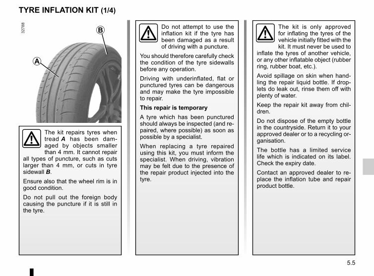
5.5
TYRE INFLATION KIT (1/4)
The kit is only approved for inflating the tyres of the vehicle initially fitted with the kit. It must never be used to
inflate the tyres of another vehicle, or any other inflatable object (rubber ring, rubber boat, etc.).Avoid spillage on skin when hand-ling the repair liquid bottle. If drop-lets do leak out, rinse them off with plenty of water.Keep the repair kit away from chil-dren.Do not dispose of the empty bottle in the countryside. Return it to your approved dealer or to a recycling or-ganisation.The bottle has a limited service life which is indicated on its label. Check the expiry date.Contact an approved dealer to re-place the inflation tube and repair product bottle.
A
B
The kit repairs tyres when tread A has been dam-aged by objects smaller than 4 mm. It cannot repair
all types of puncture, such as cuts larger than 4 mm, or cuts in tyre sidewall B.Ensure also that the wheel rim is in good condition.Do not pull out the foreign body causing the puncture if it is still in the tyre.
Do not attempt to use the inflation kit if the tyre has been damaged as a result of driving with a puncture.
You should therefore carefully check the condition of the tyre sidewalls before any operation.Driving with underinflated, flat or punctured tyres can be dangerous and may make the tyre impossible to repair.This repair is temporaryA tyre which has been punctured should always be inspected (and re-paired, where possible) as soon as possible by a specialist.When replacing a tyre repaired using this kit, you must inform the specialist. When driving, vibration may be felt due to the presence of the repair product injected into the tyre.

5.6
TYRE INFLATION KIT (2/4)Vehicle fitted with a tyre pressure loss warning systemIf under-inflated (puncture, low pres-
sure, etc.), the warning light lights up on the instrument panel. See “Tyre pressure loss warning” in Section 2.
45
1
Before using this kit, park the vehicle at a sufficient distance from traffic, switch on the hazard warning lights, apply the handbrake, ask all passen-gers to leave the vehicle and keep them away from traffic.
8
2
3
7
6
In the event of a puncture, use the kit C located in the luggage compartment in the 4x2 version or in the emergency spare wheel tray under the luggage compartment carpet in the 4x4 version.
CC
D
If the vehicle is parked on the hard shoulder, you must warn other road users of your vehicle’s presence
with a warning triangle or with other devices as per the legislation apply-ing to the country you are in.
On 4x2 versions, unclip flap D.

5.7
For all vehicles, with the engine run-ning and the handbrake applied,– unroll the hose from the container;– connect the compressor hose 3 to
the container’s inlet 8;– depending on the vehicle, connect
the container 8 to the compressor from the container recess 7;
– unscrew the valve cap on the rel-evant wheel and screw on the con-tainer’s inflation adapter 1;
– disconnect any accessories previ-ously connected to the vehicle’s ac-cessories sockets;
– adapter 2 must be connected to the vehicle accessories socket;
– press switch 4 to inflate the tyre to the recommended pressure (please refer to the information in the section on “Tyre pressure”);
– after a maximum of 15 minutes, stop inflating and read the pressure (on pressure gauge 5).
Note: while the container is empty-ing (approximately 30 seconds), the pressure gauge 5 will briefly indicate a pressure of up to 6 bar. The pres-sure will then drop.
– adjust the pressure: to increase it, continue inflation with the kit; to reduce it, press button 6.
If a minimum pressure of 1.8 bar is not reached after 15 minutes, repair is not possible; do not drive the ve-hicle but contact an approved dealer.
Nothing should be placed around the driver’s feet as such objects may slide under the pedals during
sudden braking manoeuvres and obstruct their use.
Please be aware that a poorly tightened or missing valve cap can make the tyres less airtight and lead
to pressure loss. Always use valve caps identical to the original ones and ensure they are tightly screwed on.
TYRE INFLATION KIT (3/4)

5.8
TYRE INFLATION KIT (4/4)
Once the tyre is correctly inflated, remove the kit: slowly unscrew the in-flation adapter 1 to prevent any repair product from escaping and store the container in plastic packaging to pre-vent the product from escaping.– Affix the driving recommendation
label to the dashboard where it can easily be seen by the driver;
– Put the kit away.– At the end of this initial inflation op-
eration, air will still escape from the tyre. You must drive a short distance in order to seal the hole.
– Start immediately and drive at be-tween 12 and 40 mph (20 and 60 km/h) in order to distribute the product evenly in the tyre and, after driving for 2 miles (3 km), stop and check the pressure.
– If the pressure is greater than 1.3 bar but less than the recommended pressure (refer to the label affixed to the edge of the driver’s door), read-just it. Otherwise, please contact an authorised dealer: the tyre cannot be repaired.
Precautions when using the kitThe kit should not be operated for more than 15 consecutive minutes.
1
Following repair with the kit, do not travel further than 120 miles (200 km). In addi-tion, reduce your speed and
under no circumstances exceed 48 mph (80 km/h). The sticker, which you must affix in a prominent position on the dashboard, reminds you of this.Depending on the country or local legislation, a tyre repaired with the inflation kit may need to be replaced.
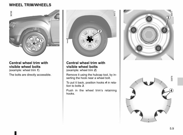
5.9
WHEEL TRIM/WHEELS
Central wheel trim with visible wheel bolts(example: wheel trim 1)The bolts are directly accessible.
Central wheel trim with visible wheel bolts(example: wheel trim 2)Remove it using the hubcap tool, by in-serting the hook near a wheel bolt.To put it back, position hooks 4 in rela-tion to bolts 3.Push in the wheel trim’s retaining hooks.
2
4
3
1
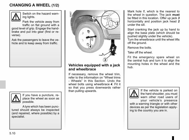
5.10
CHANGING A WHEEL (1/2)
Switch on the hazard warn-ing lights.Park the vehicle away from traffic on flat ground with a
good level of grip. Engage the hand-brake and put into gear (first or re-verse).Ask the passengers to leave the ve-hicle and to keep away from traffic.
If you have a puncture, re-place the wheel as soon as possible.A tyre which has been punc-
tured should always be inspected (and repaired, where possible) by a specialist.
Vehicles equipped with a jack and wheelbraceIf necessary, remove the wheel trim, refer to the information on “Wheel trims - Wheels” in this Section. Undo the wheel bolts using wheelbrace 4. Fit it so that you press downwards rather than pulling upwards.
Mark hole 1, which is the nearest to the wheel in question. The jack must be fitted in this location. Offer up jack 3 horizontally and position jack head 2 under the sill.Start cranking the jack up by hand to align the base plate (which should be pushed slightly under the vehicle).Turn the wheelbrace until the wheel lifts off the ground.Remove the bolts.Take off the wheel.Fit the emergency spare wheel on the central hub and turn it to align the mounting holes in the wheel and the hub.
If the vehicle is parked on the hard shoulder, you must warn other road users of your vehicle’s presence
with a warning triangle or with other devices as per the legislation apply-ing to the country you are in.
12
3
4

5.11
CHANGING A WHEEL (2/2)
If the vehicle is parked on the hard shoulder, you must warn other road users of your vehicle’s presence
with a warning triangle or with other devices as per the legislation apply-ing to the country you are in.
Note: ensure that the emergency spare wheel or punctured wheel and the wheel tray are correctly posi-tioned so that the luggage compart-ment carpet can be properly fitted.
Tighten the bolts, checking that the wheel is correctly positioned on its hub and lower the jack.With the wheels on the ground, tighten the bolts firmly, beginning on side 5, then 7, 9, 6, and finishing with 8. Check the tightness (tightening torque 105 Nm), and the pressure of the emer-gency spare wheel’s tyre as soon as possible.
If the vehicle is not equipped with a jack or wheelbrace, you can obtain these from your approved dealer.5
6
78
9
Vehicle fitted with a tyre pressure loss warning systemIf under-inflated (puncture, low pres-
sure, etc.), the warning light lights up on the instrument panel. See “Tyre pressure loss warning” in Section 2.

5.12
TYRES (1/4)Tyre and wheel safetyThe tyres are the only contact between the vehicle and the road, so it is essen-tial to keep them in good condition. You must make sure that your tyres con- -form to local road traffic regulations.
For your safety, please re-spect the speed limit.When they need to be re-placed, only tyres of the
same make, size, type and profile should be used on a single axle.They must: either have a load ca-pacity and a speed capacity at least equal to the original tyres, or correspond to those recom-mended by your authorised dealer.Failure to heed these instructions could endanger your safety and affect your vehicle’s roadworthiness.Risk of loss of control of the ve-hicle.
Maintaining the tyresThe tyres must be in good condition and the tread form must have sufficient depth; tyres approved by our Technical Department have wear warning strips 1 which are indicators moulded into the tread at several points.
When the tyre tread has been worn to the level of the warning strips, they become visible 2: it is then necessary to replace your tyres because the tread rubber is now only 1.6 mm deep at most, resulting in poor road holding on wet roads.An overloaded vehicle, long journeys by motorway, particularly in very hot weather, or continual driving on poorly surfaced minor roads will lead to more rapid tyre wear and affect safety.
Incidents which occur when driving, such as striking the kerb, may damage the tyres and wheel rims, and could
also lead to misalignment of the front or rear axle geometry. If such incidents occur, have the condition of these parts checked by an appro-ved dealer.
1
2

5.13
TYRES (2/4)
Tyre pressuresAdhere to the tyre pressures (including the emergency spare wheel). The tyre pressures should be checked at least once a month and additionally before any long journey (refer to the label af-fixed to the edge of the driver’s door).
Incorrect tyre pressures lead to abnormal tyre wear and unusually hot running. These are factors which
may seriously affect safety and lead to:– poor road holding;– risk of blowouts or throwing a
tread.The tyre pressure depends on the load and speed of use; adjust the pressures according to the condi-tions of use (refer to the information on “Tyre pressures” in Section 4).
Please be aware that a poorly tightened or missing valve cap can make the tyres less airtight and may lead to pressure loss. Always use valve caps of the same type as the originals and tighten them fully.
Pressures should be checked when the tyres are cold; ignore higher pressures which may be reached in hot weather or following a fast journey.If tyre pressures cannot be checked when the tyres are cold, assume an in-crease of 0.2 to 0.3 bar.Never deflate a hot tyre.
Special noteDepending on the vehicle, there may be an adapter which needs to be posi-tioned on the valve before air is added.
Your vehicle is equipped with large wheels. These are more sensitive to imbalance. If you experience vibra-tion while driving, contact an appro-ved dealer.
Vehicle fitted with a tyre pressure loss warning system If under-inflated (puncture, low pres-
sure, etc.), the warning light on the instrument panel comes on. See «Tyre pressure loss warning» in chap-ter 2.

5.14
TYRES (3/4)
Changing wheels aroundWe recommend that you swap the wheels regularly in order to ensure that the tyres wear evenly.Swap the wheels as shown in the above diagram. Refer to your vehicle’s main-tenance document for the intervals.
Emergency spare wheelRefer to the information on the “Emergency spare wheel” and “Changing a wheel” in Section 5.
Fitting new tyres
For safety reasons, this operation must be carried out by a specialist.Fitting different tyres may
change your vehicle as follows:– it may mean that your vehicle no
longer conforms to current regu-lations;
– It may change the way it handles when cornering;
– It may cause the steering to be heavy;
– it may affect the use of snow chains.

5.15
TYRES (4/4)Snow or Winter tyresWe would recommend that these be fitted to all four wheels to ensure that your vehicle retains maximum adhe-sion.Warning: These tyres sometimes have a specific direction of rotation and a maximum speed index which may be lower than the maximum speed of your vehicle.
Studded tyresThis type of equipment may only be used for a limited period and as laid down by local legislation.It is necessary to observe the speed specified by current legislation.These tyres must, at a minimum, be fitted to the two front wheels.
In all cases, we would recommend that you contact your approved dealer who will be able to advise you on the choice of equipment which is most suitable for your vehicle.
Use in winterChains2-wheel drive version (2WD)Snow chains must be fitted to the front wheels.4-wheel drive version (4WD)Snow chains may be fitted to only the front wheels, or to all four wheels.
It is forbidden to fit snow chains to only the rear wheels.Snow chains may only be
fitted to tyres of the same size as those originally fitted to your vehicle.Only certain chains can be fitted to tyres.Consult an approved dealer.
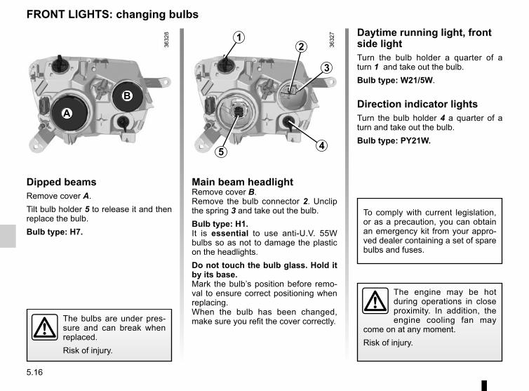
5.16
FRONT LIGHTS: changing bulbs
Dipped beamsRemove cover A.Tilt bulb holder 5 to release it and then replace the bulb.Bulb type: H7.
Main beam headlightRemove cover B.Remove the bulb connector 2. Unclip the spring 3 and take out the bulb.Bulb type: H1.It is essential to use anti-U.V. 55W bulbs so as not to damage the plastic on the headlights.Do not touch the bulb glass. Hold it by its base.Mark the bulb’s position before remo-val to ensure correct positioning when replacing.When the bulb has been changed, make sure you refit the cover correctly.
Daytime running light, front side lightTurn the bulb holder a quarter of a turn 1 and take out the bulb.Bulb type: W21/5W.
Direction indicator lightsTurn the bulb holder 4 a quarter of a turn and take out the bulb.Bulb type: PY21W.
A
B
5
1
3
2
4
The engine may be hot during operations in close proximity. In addition, the engine cooling fan may
come on at any moment.Risk of injury.
To comply with current legislation, or as a precaution, you can obtain an emergency kit from your appro-ved dealer containing a set of spare bulbs and fuses.
The bulbs are under pres-sure and can break when replaced.Risk of injury.
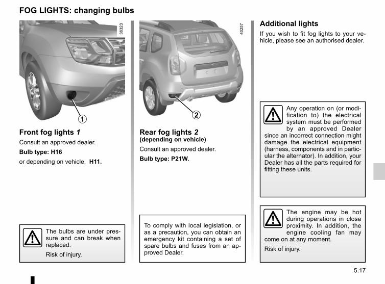
5.17
Additional lightsIf you wish to fit fog lights to your ve-hicle, please see an authorised dealer.
FOG LIGHTS: changing bulbs
Front fog lights 1Consult an approved dealer.Bulb type: H16or depending on vehicle, H11.
Any operation on (or modi-fication to) the electrical system must be performed by an approved Dealer
since an incorrect connection might damage the electrical equipment (harness, components and in partic-ular the alternator). In addition, your Dealer has all the parts required for fitting these units.
The engine may be hot during operations in close proximity. In addition, the engine cooling fan may
come on at any moment.Risk of injury.
The bulbs are under pres-sure and can break when replaced.Risk of injury.
1
To comply with local legislation, or as a precaution, you can obtain an emergency kit containing a set of spare bulbs and fuses from an ap-proved Dealer.
Rear fog lights 2(depending on vehicle)Consult an approved dealer.Bulb type: P21W.
2
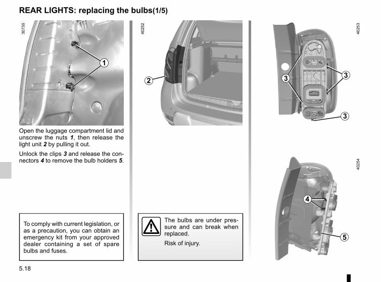
5.18
REAR LIGHTS: replacing the bulbs(1/5)
The bulbs are under pres-sure and can break when replaced.Risk of injury.
1
2 3 3
3
4
5
Open the luggage compartment lid and unscrew the nuts 1, then release the light unit 2 by pulling it out.Unlock the clips 3 and release the con-nectors 4 to remove the bulb holders 5.
To comply with current legislation, or as a precaution, you can obtain an emergency kit from your approved dealer containing a set of spare bulbs and fuses.

5.19
REAR LIGHTS: replacing the bulbs(2/5)
6 Side lightConsult an approved Dealer.
7 Direction indicator lightsWY 16 W bulb.
8 Brake lightPear-shaped, bayonet type P 21 W bulb with two filaments.
9 Reversing lightPear-shaped, bayonet type bulb P 21 W.
6
RefittingTo refit, proceed in the reverse order, taking care not to damage the wiring.
7
8
9
5

5.20
REAR LIGHTS: replacing the bulbs(3/5)
Open the luggage compartment lid and unscrew the nuts 10, then release the light unit 11 by pulling it out.Unlock the clips 12 to remove the bulb holders 13.14 Side light and brake light
Pear-shaped, bayonet type bulb with two P 21/5 W filaments.
15 Direction indicator lightsPear-shaped, bayonet type P 21 W or PY 21 W bulb (depending on ve-hicle).
16 Reversing lightPear-shaped bayonet bulb P 21 W or,Rear fog light(depending on vehicle)Pear-shaped, bayonet type P 21 W bulb.
RefittingTo refit, proceed in the reverse order, taking care not to damage the wiring.
10
11 1212
13
14
15
16
The bulbs are under pres-sure and can break when replaced.Risk of injury.
13

5.21
REAR LIGHTS: replacing the bulbs(4/5)
High-level brake lightThe bulb for high-level brake light 18 may be accessed through the luggage compartment.Carefully unclip cover 17 by pressing tabs 19.
Carefully unclip tab 21 (movement A) and turn it an eighth of a turn (move-ment B) to release bulb holder 20.
Remove bulb 22.Bulb type: W 16 W.
17 18
19
20A
B21 22
To comply with current legislation, or as a precaution, you can obtain an emergency kit from your approved dealer containing a set of spare bulbs and fuses.
The bulbs are under pres-sure and can break when replaced.Risk of injury.
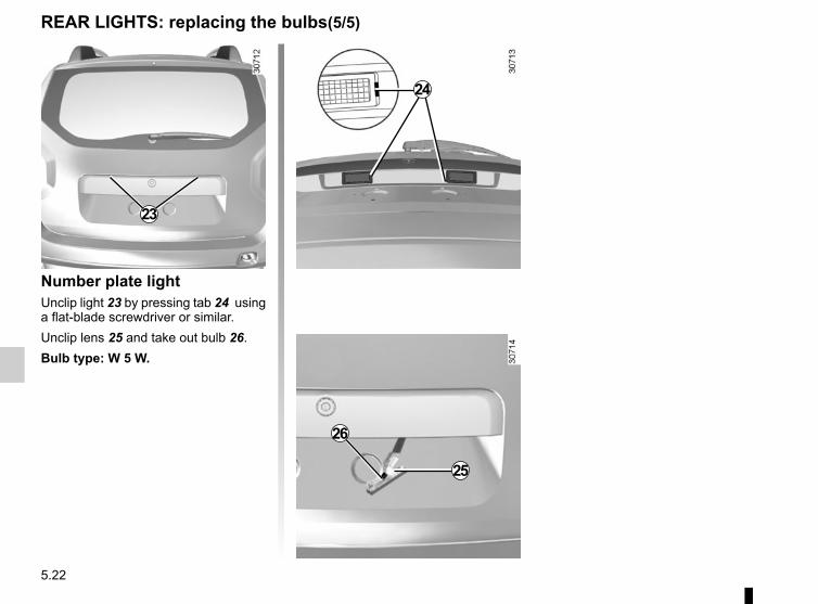
5.22
REAR LIGHTS: replacing the bulbs(5/5)
Number plate lightUnclip light 23 by pressing tab 24 using a flat-blade screwdriver or similar.Unclip lens 25 and take out bulb 26.Bulb type: W 5 W.
23
24
25
26

5.23
INDICATOR LIGHTS: changing bulbs
Unclip indicator light 1 (using a flat-blade screwdriver or similar positioned at A to move the indicator light towards the outside of the vehicle).Turn bulb holder 2 a quarter of a turn (movement B) and take out bulb 3 (movement C).Bulb type: WY5W.
The bulbs are under pres-sure and can break when replaced.Risk of injury.
A
1
B
2
3
C
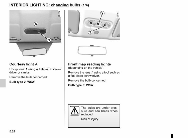
5.24
INTERIOR LIGHTING: changing bulbs (1/4)
Courtesy light AUnclip lens 1 using a flat-blade screw-driver or similar.Remove the bulb concerned.Bulb type 2: W5W.
Front map reading lights(depending on the vehicle)Remove the lens 1 using a tool such as a flat-blade screwdriver.Remove the bulb concerned.Bulb type 3: W5W.
The bulbs are under pres-sure and can break when replaced.Risk of injury.
1
2
3
A
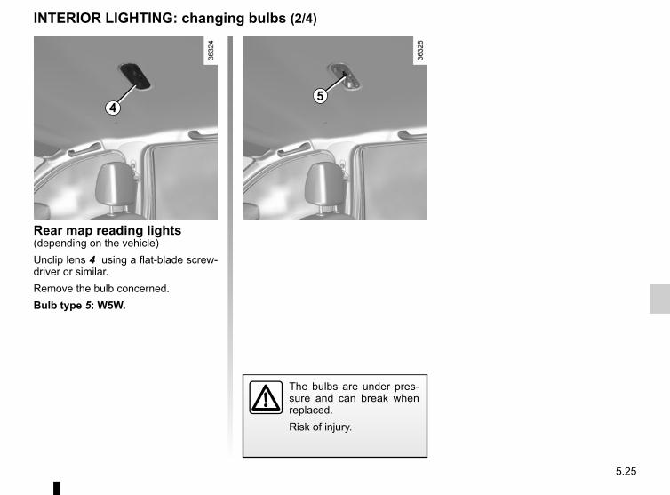
5.25
INTERIOR LIGHTING: changing bulbs (2/4)
Rear map reading lights(depending on the vehicle)Unclip lens 4 using a flat-blade screw-driver or similar.Remove the bulb concerned.Bulb type 5: W5W.
The bulbs are under pres-sure and can break when replaced.Risk of injury.
45
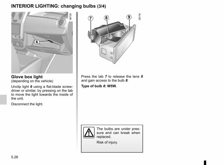
5.26
INTERIOR LIGHTING: changing bulbs (3/4)
Glove box light(depending on the vehicle)Unclip light 6 using a flat-blade screw-driver or similar, by pressing on the tab to move the light towards the inside of the unit.Disconnect the light.
Press the tab 7 to release the lens 9 and gain access to the bulb 8.Type of bulb 8: W5W.
The bulbs are under pres-sure and can break when replaced.Risk of injury.
7 8 9
6

5.27
INTERIOR LIGHTING: changing bulbs (4/4)
Luggage compartment lightUnclip light 10 using a flat-blade screw-driver or similar, by pressing on tab 11 to move the light towards the inside of the luggage compartment.
Press tab 12 to release lens 13. Remove the bulb 14.Type of bulb 14: W5W.
The bulbs are under pres-sure and can break when replaced.Risk of injury.
10
11
13
14
12

5.28
Passenger compartment fusesIf any electrical component does not work, check the condition of the fuses.Unclip flap A using notch 1 to help you.Depending on the vehicle, to identify the fuses, refer to the fuse allocation label located at the back of the flap A and shown on the following pages.
Check the fuse in question and replace it, if necessary, with a fuse of the same rating.
If a fuse is fitted where the rating is too high, it may cause the electrical circuit to overheat (risk of fire) in the event of an item of equipment using an excessive amount of current.
To comply with current legislation, or as a precaution, you can obtain an emergency kit from your appro-ved Dealer containing a set of spare bulbs and fuses.
FUSES (1/8)
Tweezers 2Remove the fuse using tweezers 2, lo-cated at the back of flap A.To remove the fuse from the tweezers, slide the fuse to the side.It is not advisable to use the free fuse locations.
2
1
A
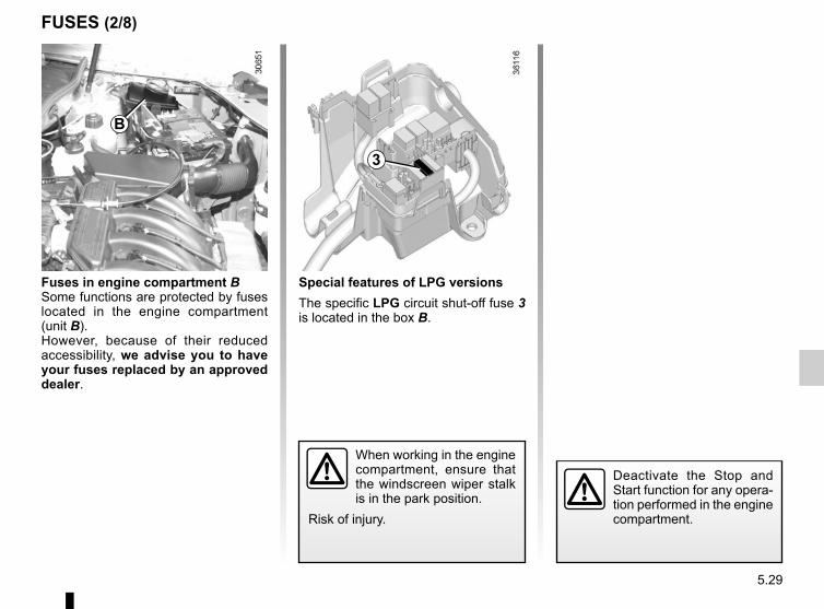
5.29
FUSES (2/8)
Fuses in engine compartment BSome functions are protected by fuses located in the engine compartment (unit B).However, because of their reduced accessibility, we advise you to have your fuses replaced by an approved dealer.
B
Special features of LPG versionsThe specific LPG circuit shut-off fuse 3 is located in the box B.
3
When working in the engine compartment, ensure that the windscreen wiper stalk is in the park position.
Risk of injury.
Deactivate the Stop and Start function for any opera-tion performed in the engine compartment.

5.30
FUSES (3/8)
Allocation of fuses in the passenger compartment, left-hand drive vehicles(the presence of certain fuses DEPENDS ON THE VEHICLE EQUIPMENT LEVEL)
A B C D E
1
8
15
24
2
9
16
25
3
10
17
26
4
11
18
27
5
12
19
28
6
13
20
29
7
14
21
30
22
31
23
32
37
38
39
33
34
35
36

5.31
Number Allocation
A Driver’s side window winder
B 4-wheel drive (4WD) transmission
C LPG
D Rear accessories socket
E Passenger compartment ECU, starter
1 Front electric window
2 Left-hand main beam headlight
3 Right-hand main beam headlight
4 Left-hand dipped beam headlight
5 Right-hand dipped beam headlight
6 Rear lights
7 Front side lights
8 Rear electric windows
Number Allocation
9 Rear fog lights
10 Horn
11 Automatic door locking
12 ABS-ESC, brake switch, clutch switch
13 Interior lights, boot light, glovebox light
14 Empty location
15 Windscreen wiper
16
Cruise control/Speed limiter, unfastened seat belt warning, parking distance control, multimedia, air conditioning, heated seats, automatic gearbox lever, UCH
Number Allocation
17 Daytime running lights
18 Brake lights
19Injection, instrument panel or dashboard, passenger compartment, sequential gearbox lever
20 Airbag
214-wheel drive transmission (4WD), LPG, automatic gearbox, sequential gearbox, reverse gear
22 Power-assisted steering
23
Heated rear windscreen, heated seats, seatbelt alarm, parking distance control, additional passenger compartment heating, cruise control/speed limiter, heated windscreen
FUSES (4/8)

5.32
FUSES (5/8)
Number Allocation
24 Passenger compartment ECU
25 Passenger compartment ECU
26 Direction indicator lights
27 and 29 Steering column control
28 Not used
30 Not used
31 Instrument panel
32
Radio, passenger compartment air conditioning control panel, passenger compartment ventilation, rear accessories socket
33 Cigar lighter
34 Diagnostics and radio socket
35 Defrosting rearview mirror
36 Electric door mirrors
37 Passenger compartment ECU, starter
Number Allocation
38 Front windscreen wiper
39 Passenger compartment ventilation
Check the fuse in question and replace it, if necessary, with a fuse of the same rating.
If a fuse is fitted where the rating is too high, it may cause the electrical circuit to overheat (risk of fire) in the event of an item of equipment using an excessive amount of current.
To comply with current legislation, or as a precaution, you can obtain an emergency kit from your appro-ved Dealer containing a set of spare bulbs and fuses.

5.33
FUSES (6/8)
Allocation of fuses in the passenger compartment, right-hand drive vehicles(the presence of certain fuses DEPENDS ON THE VEHICLE EQUIPMENT LEVEL)
A B C D E
1
8
15
24
2
9
16
25
3
10
17
26
4
11
18
27
5
12
19
28
6
13
20
29
7
14
21
30
22
31
23
32
33
34
35
36
37
38
39

5.34
FUSES (7/8)
Number Allocation
A Driver’s side window winder
B 4-wheel drive (4WD) transmission
C Rear air conditioning
D Rear accessories socket
E Passenger compartment ECU, starter
1 Front electric window
2 Left-hand main beam headlight
3 Right-hand main beam headlight
4 Left-hand dipped beam headlight
5 Right-hand dipped beam headlight
6 Rear lights
7 Front side lights
Number Allocation
8 Rear electric windows
9 Rear fog lights
10 Horn
11 Automatic door locking
12 ABS-ESC, brake switch
13 Interior lights, boot light, glovebox light
14 Not used
15 Windscreen wiper
16 Multimedia
17 Daytime running lights
Number Allocation
18 Brake lights
19Injection, instrument panel or dashboard, passenger compartment, sequential gearbox lever
20 Airbag
21 4-wheel drive transmission (4WD), reverse gear
22 Power-assisted steering
23
Cruise control/Speed limiter, rear windscreen, unfastened seatbelt warning, parking distance control, additional passenger compartment heating

5.35
FUSES (8/8)
Number Allocation
24 Passenger compartment ECU
25 Not used
26 Direction indicator lights
27 and 29 Steering column control
28 Not used
30 Not used
31 Instrument panel
32
Radio, passenger compartment air conditioning control panel, passenger compartment ventilation, rear accessories socket
33 Cigar lighter
34 Diagnostics and radio socket
35 Defrosting rearview mirror
36 Electric door mirrors
37 Passenger compartment ECU, starter
Number Allocation
38 Front windscreen wiper
39 Passenger compartment ventilation
Check the fuse in question and replace it, if necessary, with a fuse of the same rating.
If a fuse is fitted where the rating is too high, it may cause the electrical circuit to overheat (risk of fire) in the event of an item of equipment using an excessive amount of current.
To comply with current legislation, or as a precaution, you can obtain an emergency kit from your appro-ved Dealer containing a set of spare bulbs and fuses.
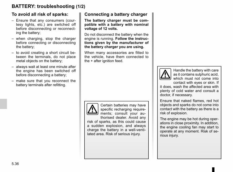
5.36
BATTERY: troubleshooting (1/2)
To avoid all risk of sparks:– Ensure that any consumers (cour-
tesy lights, etc.) are switched off before disconnecting or reconnect-ing the battery;
– when charging, stop the charger before connecting or disconnecting the battery;
– to avoid creating a short circuit be-tween the terminals, do not place metal objects on the battery;
– always wait at least one minute after the engine has been switched off before disconnecting a battery;
– make sure that you reconnect the battery terminals after refitting.
Handle the battery with care as it contains sulphuric acid, which must not come into contact with eyes or skin. If
it does, wash the affected area with plenty of cold water and consult a doctor, if necessary.Ensure that naked flames, red hot objects and sparks do not come into contact with the battery as there is a risk of explosion.The engine may be hot during oper-ations in close proximity. In addition, the engine cooling fan may start to operate at any moment. Risk of se-rious injury.
Certain batteries may have specific recharging require-ments; consult your au-thorised dealer. Avoid any
risk of sparks, as this could cause a sudden explosion, and always charge the battery in a well-venti-lated area. Risk of serious injury.
Connecting a battery chargerThe battery charger must be com-patible with a battery with nominal voltage of 12 volts.Do not disconnect the battery when the engine is running. Follow the instruc-tions given by the manufacturer of the battery charger you are using.When many accessories are fitted to the vehicle, have them connected to the + after ignition feed.

5.37
BATTERY: troubleshooting (2/2)
Starting the vehicle using the battery from another vehicleIf you have to use the battery from an-other vehicle to start, obtain suitable jump leads (with a large cross section) from an approved dealer or, if you al-ready have jump leads, ensure that they are in perfect condition.The two batteries must have an iden-tical nominal voltage of 12 volts. The battery supplying the current should have a capacity (amp-hours, Ah) which is at least the same as that of the dis-charged battery.Ensure that there is no risk of contact between the two vehicles (risk of short circuiting when the positive terminals are connected) and that the discharged battery is properly connected. Switch off your vehicle ignition.Start the engine of the vehicle supply-ing the current and run it at an interme-diate engine speed.
Connect the positive (+) lead A to (+) terminal 1 of the discharged battery, then to (+) terminal 2 of the battery sup-plying the current.Connect the negative (–) lead B to (–) terminal 3 of the battery supplying the current and then to (–) terminal 4 of the discharged battery.Start the engine as normal. As soon as it is running, disconnect leads A and B in the reverse order (4-3-2-1)
Check that there is no con-tact between leads A and B and that the positive lead A is not touching any metal
parts on the vehicle supplying the current.Risk of injury and/or damage to the vehicle.
A
B
1 4
2 3
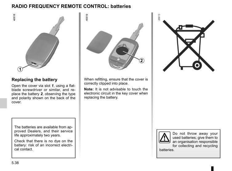
5.38
Replacing the batteryOpen the cover via slot 1, using a flat-blade screwdriver or similar, and re-place the battery 2, observing the type and polarity shown on the back of the cover.
When refitting, ensure that the cover is correctly clipped into place.Note: It is not advisable to touch the electronic circuit in the key cover when replacing the battery.
Do not throw away your used batteries; give them to an organisation responsible for collecting and recycling
batteries.
RADIO FREQUENCY REMOTE CONTROL: batteries
The batteries are available from ap-proved Dealers, and their service life approximately two years.Check that there is no dye on the battery: risk of an incorrect electri-cal contact.
1
2

5.39
WIPER BLADES
Replacing windscreen wiper blades 1– With the ignition off, lift wiper arm 3.– Turn the blade horizontally (move-
ment A).– Press tab 2 and slide the wiper blade
downwards (movement D) until hook 4 on the wiper arm is released.
– Slide the blade (movement C) then lift it (movement B) to release it.
Replacing the rear screen wiper blades 5– With the ignition off, lift wiper arm 6.– Turn blade 5 until some resistance is
met (movement E).– Pull the blade to release it (move-
ment F).
Refitting windscreen wiper bladesTo refit the wiper blade, proceed in the reverse order to removal. Make sure that the blade is correctly locked in po-sition.
Check the condition of the wiper blades. You are responsible for their service life:– clean the blades, windscreen and
rear screen regularly with soapy water;
– do not use them when the wind-screen or rear screen are dry;
– free them from the windscreen or rear screen when they have not been used for a long time.
– In frosty weather, make sure that the wiper blades are not stuck by ice (to avoid the risk of the motor
overheating).– Check the condition of the wiper
blades.Replace the wiper blades as soon as they begin to lose efficiency (approximately once a year).
Whilst changing the blade, take care not to drop the arm onto the window after it has been removed as this may break the window.
234
A
C
1
BD
5 6
F
E

5.40
TOWING: breakdown (1/3)Before any towing, put the gears into neutral (neutral position for vehicles equipped with a manual gearbox or N position for vehicles equipped with an automatic gearbox).Unlock the steering column; the igni-tion key must be in “M” position (ig-nition) to enable signalling (“Stop” lights, hazard warning lights, etc.). Always switch on the lights when driving at night.Release the parking brake.It is also essential to observe the towing regulations imposed by current legisla-tion in your country. Please contact an authorised dealer. Front and rear towing points
Only use the front 1 and rear 2 towing points.Depending on the vehicle, unclip the cover 3 by inserting a flat tool under the cover.
When the engine is stop-ped, steering and braking assistance are not opera-tional.
Do not remove the key from the ignition when the vehi-cle is being towed.
– Use a rigid towing bar. If a rope or cable is used (where the law allows this), the vehicle being towed must be able to brake.– A vehicle must not be towed if it is not fit to be driven.– Avoid accelerating or braking suddenly when towing, as this may result
in damage being caused to the vehicle.– When towing a vehicle, it is advisable not to exceed 30 mph (50 km/h).– Do not push the vehicle if the steering column is locked.
These towing points may only be used for towing: never use them for lifting the vehicle directly or indirectly.
123

5.41
TOWING: breakdown (2/3)
4-wheel drive vehicles (4WD)Whichever type of gearbox is fitted, a 4WD vehicle must never be towed if any of its 4 wheels are touching the ground.
Off-road recoveryIf your vehicle is stuck in sand, snow or mud, attach a flexible towing device (towing belt or other device specially designed for this purpose) to the front or rear towing point (refer to the in-formation on “Front and rear towing points” on the previous page).
For off-road recovery, it is forbidden to use a rigid bar to tow a vehicle that is stuck. Risk of mechanical
damage.
You must never tow a 4-wheel drive vehicle, irrespective of the mode se-lected, if one of the 4 wheels is in contact with the ground (except for off-road recovery). Risk of mechani-cal damage.
Refer to the manufacturer’s instruc-tions for information on how to fit and operate the equipment.If a 4x4 (4WD) vehicle becomes stuck, it should only be towed for a short distance. Risk of mechanical damage.
Do not leave the tools unse-cured inside the vehicle as they may come loose under braking.

5.42
TOWING: breakdown (3/3)
When storing the tools, ensure they are securely re-placed in the luggage com-partment, in their original
position.Do not leave the tools unsecured inside the vehicle as they may come loose under braking.
4
5
Towing a vehicle with an automatic gearboxWhen the engine is switched off, the gearbox is no longer lubricated. It is preferable to tow this type of vehicle on a trailer or, for 4x2 (2WD) vehicles only, tow it with the rear wheels off the ground.Under exceptional circumstances and for 4x2 (2WD), vehicles only, you may tow the vehicle with all four wheels on the ground, only going forward, with the gear lever in neutral position N and for a distance not exceeding 30 miles (50 km).If the gear lever cannot be put into the N position, please consult an authori-sed dealer.
When setting off, if the lever is locked in position P even though you are pres-sing the brake pedal, the lever can be released manually.To do this, unclip the base of the lever, simultaneously press recess 4 and the unlocking button 5.
Depending on the vehicle, unclip the base of the lever, then insert a tool (rigid rod) into the slot 6 and simulta-neously press the button 7 in order to unlock the lever.Contact an authorised dealer as soon as possible.
6
7

5.43
Location for front speaker 2 or rear speaker 3Unclip the cover using a flat-blade screwdriver or similar.
FITTED AUDIO EQUIPMENT
Radio location 1If your vehicle is not fitted with an audio system, one can be fitted and locations have been provided for:– the radio 1;– front speakers 2;– rear speakers 3.To install any equipment, please con-sult an approved dealer. Unclip and remove storage compart-ment 1.
– In all cases, it is very important to follow the manufacturer’s instructions care-fully.
– The specifications of the brackets and wires (available from our network) vary depending on the equipment level of your vehicle and the type of radio. Consult an authorised dealer to find out the correct part number.
– No work may be carried out on the vehicle’s electrical or radio circuits, except by approved Dealers: an incorrectly connected system may result in damage being caused to the electrical equipment and/or the components connected to it.
1
23

5.44
ACCESSORIES
Electrical and electronic accessoriesBefore installing this type of accessory (particularly for transmitters/receivers: frequency bandwidth, power level, po-sition of the aerial, etc.), make sure it is compatible with your vehicle. You can get advice from an authorised dealer.Connect accessories with a maximum power of 120 Watts only. Fire hazard. When several accessory sockets are
used at the same time, the total power of the connected accessories must not exceed 180 watts.No work may be carried out on the vehicle’s electrical or radio circuits, except by authorised dealers: an incorrectly connected system may result in damage being caused to the electrical equipment and/or the components connected to it.If the vehicle is fitted with any aftermarket electrical equipment, make sure that the installation is correctly protected by a fuse. Establish the rating and position of this fuse.
Using the diagnostic socketThe use of electronic accessories on the diagnostic socket may cause serious disturbance to the vehicle’s electronic systems. For your safety we recommend that you use only electronic accessories approved by the manufacturer, consult an Approved Dealer. Serious accident risk.
Use of transmitting/receiving devices (telephones, CB equipment etc.).Telephones and CB equipment with integrated aerials may cause interference to the electronic systems originally fitted to the vehicle: it is advisable only to use equipment with an external aerial. Furthermore, we remind you of the need to conform to the legislation in force concerning the use of such equipment.
Fitting aftermarket accessoriesIf you wish to install accessories on the vehicle: please contact an authorised dealer. Also, to ensure the correct operation of your vehicle, and to avoid any risk to your safety, we recommend that you use only accessories specifically designed for your vehicle, which are the only accessories for which the manufacturer will provide a warranty.If you are using an anti-theft device, only attach it to the brake pedal.Obstructions to the driverOn the driver’s side, only use mats suitable for the vehicle, attached with the pre-fitted components, and check the fitting regu-larly. Do not lay one mat on top of another. There is a risk of wedging the pedals.
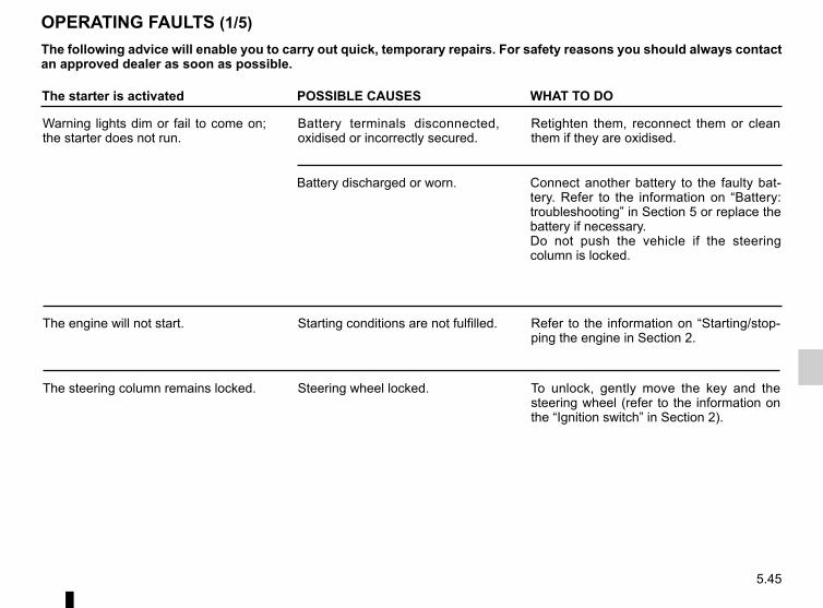
5.45
OPERATING FAULTS (1/5)The following advice will enable you to carry out quick, temporary repairs. For safety reasons you should always contact an approved dealer as soon as possible.
The starter is activated POSSIBLE CAUSES WHAT TO DO
Warning lights dim or fail to come on; the starter does not run.
Battery terminals disconnected, oxidised or incorrectly secured.
Retighten them, reconnect them or clean them if they are oxidised.
Battery discharged or worn. Connect another battery to the faulty bat-tery. Refer to the information on “Battery: troubleshooting” in Section 5 or replace the battery if necessary.Do not push the vehicle if the steering column is locked.
The engine will not start. Starting conditions are not fulfilled. Refer to the information on “Starting/stop-ping the engine in Section 2.
The steering column remains locked. Steering wheel locked. To unlock, gently move the key and the steering wheel (refer to the information on the “Ignition switch” in Section 2).

5.46
OPERATING FAULTS (2/5)
On the road POSSIBLE CAUSES WHAT TO DO
Vibrations. Tyres not inflated to correct pres-sures, incorrectly balanced or damaged.
Check the tyre pressures; if this is not the cause, have their condition checked by an approved dealer.
Coolant boiling in the coolant reservoir.
Mechanical fault: cylinder head gasket damaged, faulty coolant pump.
Stop the engine.Contact an approved dealer.
Engine cooling fan not working. Contact an approved dealer.
Smoke under the bonnet. Short circuit or cooling system leak.
Stop, switch off the ignition, move away from the vehi-cle and contact an approved dealer.
The oil pressure warning light comes on:
on a bend or under braking The engine oil level is too low. Top up the engine oil level (refer to the information on “Engine oil level: topping up/filling” in Section 4).
at idle speed Low oil pressure. Go to your nearest approved dealer.
The oil pressure warning light takes a long time to go out or remains lit during acceleration.
Loss of oil pressure. Stop the vehicle: contact an approved dealer.

5.47
OPERATING FAULTS (3/5)
On the road POSSIBLE CAUSES WHAT TO DO
Abnormal white smoke from the ex-haust
Mechanical fault: damaged cylinder head gasket.or
Stop the engine.Contact an approved dealer.
This is not necessarily a fault. Smoke may be caused by regeneration of the particle filter.
Please refer to the information on “Special features of diesel versions” in Section 2.
The power-assisted steering be-comes heavy.
Belt broken. Have the belt replaced.
No power-assisted steering oil For maintenance operations on the power-assisted steering, contact an authorised dealer.
The “2WD” mode and electronic fault warning lights come on.
Fault in the 4-wheel drive system. Drive as soon as possible at a moderate speed to an approved dealer. The problem may be resolved by replacing the wheels.
The system will not switch to “2WD” or “4WD Lock” mode. “AUTO” mode remains active.
Fault in the 4-wheel drive system. Contact an approved dealer as soon as possible.

5.48
OPERATING FAULTS (4/5)
Radiator: If there is a significant lack of coolant, remember that it must never be topped up using cold coolant while the engine is very warm. After any procedure on the vehicle which has involved even partial draining of the cooling system, it must be refilled with a new mixture prepared in the correct proportions. Reminder: only products approved by the Technical Department may be used for this purpose.
On the road POSSIBLE CAUSES WHAT TO DO
Whistling Roof aerial poorly positioned. Position the aerial.
The engine overheats. The coolant temperature indicator light comes on.
Engine cooling fan not working. Stop the vehicle, switch off the engine and contact an approved dealer.
Coolant leaks. Stop the vehicle, switch off the engine and check the coolant reservoir: it should con-tain fluid. If there is no coolant, consult an approved dealer as soon as possible.
The oil change warning light remains lit after an oil change.
Warning not reset after oil change. Reset the warning after changing the oil; refer to the information in the paragraph on the “On-board computer” in Section 1.

5.49
OPERATING FAULTS (5/5)
Electrical equipment POSSIBLE CAUSES WHAT TO DO
The wipers do not work. Wiper blades stuck. Free the blades before using the wipers.
Faulty electrical circuit. Consult an approved dealer.
The wiper does not stop. Faulty electrical controls. Consult an approved dealer.
Direction indicators flashing more quickly.
Blown bulb. Replace the bulb.
The direction indicators do not work. Faulty electrical circuit. Consult an approved dealer.
The headlights do not switch on or off. Faulty electrical circuit or control. Consult an approved dealer
Traces of condensation in the lights. This is not a fault. Traces of condensa-tion are a natural phenomenon caused by variations in temperature.The traces will disappear slowly once the lights are switched on.

5.50

6.1
Section 6: Technical specifications
Vehicle identification plate . . . . . . . . . . . . . . . . . . . . . . . . . . . . . . . . . . . . . . . . . . . . . . . . . . . . . . . . . 6.2Engine identification plate . . . . . . . . . . . . . . . . . . . . . . . . . . . . . . . . . . . . . . . . . . . . . . . . . . . . . . . . . 6.3Dimensions . . . . . . . . . . . . . . . . . . . . . . . . . . . . . . . . . . . . . . . . . . . . . . . . . . . . . . . . . . . . . . . . . . . . 6.5Engine specifications . . . . . . . . . . . . . . . . . . . . . . . . . . . . . . . . . . . . . . . . . . . . . . . . . . . . . . . . . . . . . 6.6Weights/Towing weights . . . . . . . . . . . . . . . . . . . . . . . . . . . . . . . . . . . . . . . . . . . . . . . . . . . . . . . . . . 6.7Replacement parts and repairs . . . . . . . . . . . . . . . . . . . . . . . . . . . . . . . . . . . . . . . . . . . . . . . . . . . . . 6.8Service sheets . . . . . . . . . . . . . . . . . . . . . . . . . . . . . . . . . . . . . . . . . . . . . . . . . . . . . . . . . . . . . . . . . . 6.9Anticorrosion check . . . . . . . . . . . . . . . . . . . . . . . . . . . . . . . . . . . . . . . . . . . . . . . . . . . . . . . . . . . . . . 6.15
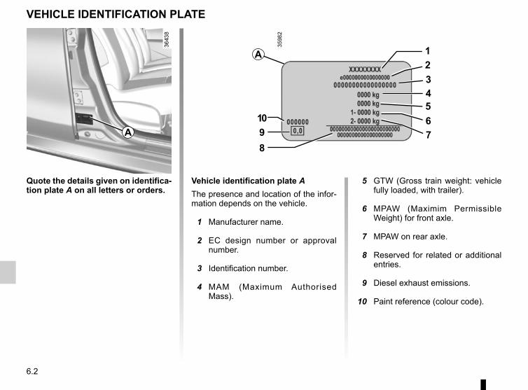
6.2
Quote the details given on identifica-tion plate A on all letters or orders.
VEHICLE IDENTIFICATION PLATE
Vehicle identification plate AThe presence and location of the infor-mation depends on the vehicle.
1 Manufacturer name.
2 EC design number or approval number.
3 Identification number.
4 MAM (Maximum Authorised Mass).
5 GTW (Gross train weight: vehicle fully loaded, with trailer).
6 MPAW (Maximim Permissible Weight) for front axle.
7 MPAW on rear axle.
8 Reserved for related or additional entries.
9 Diesel exhaust emissions.
10 Paint reference (colour code).
A
1234567
8910
A

6.3
ENGINE IDENTIFICATION PLATES (1/2)
Quote the information on the identi-fication plate or label A in all corre-spondence or when ordering parts.(Location varies depending on engine) 1 Engine type. 2 Engine suffix. 3 Engine number.
A
A
21
3A
A
1 2
3
A
A

6.4
ENGINE IDENTIFICATION PLATES (2/2)
Please quote the information on the engine plate or label A in all corre-spondence or orders.(Location varies depending on engine) 1 Engine type. 2 Engine suffix. 3 Engine number.
A
21
3
A
A

6.5
DIMENSIONS (in metres)
0.822 2.673 0.8204.315
1.560
1.634 (1)1.690 (2)
(1) unladen, without roof bars(2) unladen, with roof bars
1.567
1.822

6.6
ENGINE SPECIFICATIONS
Versions 1.6 16V 1.6 16V 2.0 16V 1.2 16V 1.5 dCi
Engine type(see engine plate)
K4M H4M F4R H5Ft K9K
Cubic capacity (cc) 1,598 1598 1 998 1 198 1,461
Type of fuelOctane rating
PetrolThe use of unleaded petrol is essential, with the octane rating as stated on the label inside the fuel filler flap.
DieselThe label located in the fuel filler flap in-dicates authorised fuels.
Spark plugs Only use spark plugs specified for your vehicle’s engine.The type should be marked on a label stuck inside the engine compart-ment. If it is not then contact your authorised dealer.Fitting spark plugs other than those specified may damage the engine.

6.7
WEIGHTS (in kg)
Versions 4x2 4x4
Maximum permissible all-up weight (MMAC)Total train weight (MTR)
Weights shown on the vehicle identification plate (refer to the information on “Vehicle identification plates” in Section 6)
Braked Trailer Weight* found by calculating: MTR - MMACUnbraked trailer weight* 580 640Permissible nose weight* 75Maximum permissible load on roof with a carrying device 80 (including the carrying device)
*Towing weight (towing a caravan, boat, etc.)Towing is prohibited when the GTW - MAM calculation is equal to zero, or when the GTW is equal to zero (or is not listed) on the identification plate.– It is important to comply with the towing weights, governed by local legislation in each country and, in particular, laid down in
the Road Traffic Regulations. Contact an authorised dealer for any towing equipment modifications.– For vehicles fitted with a trailer, the gross train weight (vehicle + trailer) must never be exceeded. However, the following
is tolerated:– the Maximum permissible weight at the rear may be exceeded by no more than 15%,– the maximum permissible all-up weight may be exceeded by no more than 10% or 100 kg (whichever occurs first).
In either case, the maximum speed of the vehicle and trailer must not exceed 60 mph (100 km/h) and the tyre pressures must be increased by 0.2 bar (3 PSI).
– The engine output and climbing capability are reduced with altitude. We recommend that the maximum load be reduced by 10% at an altitude of 1,000 metres and by an additional 10% for each 1,000 metres thereafter.
Weight transfer (depending on the vehicle)If the Maximum Authorised Mass of the vehicle has not been reached, up to 200 kg can be transferred to the braked trailer, within the limits of the Gross Train Weight.
The weights shown are for a basic vehicle without options: they will vary depending on the equipment level of your ve-hicle. Please consult an authorised dealer.

6.8
SPARE PARTS AND REPAIRSOriginal parts are based on strict specifications and are subject to highly-specialised tests. Therefore, they are of at least the same level of quality as the parts fitted originally.If you always fit genuine replacement parts to your vehicle, you will ensure that it performs well. Furthermore, repairs carried out within the manufacturer’s Network using original parts are guaranteed according to the conditions set out on the reverse of the repair order.

6.9
Date: Miles (Km): Invoice number: Comments/miscellaneousType of operation: StampService □....................................... □Anti-corrosion check:OK □ Not OK* □*See specific page
Date: Miles (Km): Invoice number: Comments/miscellaneousType of operation: StampService □....................................... □Anti-corrosion check:OK □ Not OK* □*See specific page
Date: Miles (Km): Invoice number: Comments/miscellaneousType of operation: StampService □....................................... □Anti-corrosion check:OK □ Not OK* □
*See specific page
VIN: ..................................................................................
SERVICE SHEETS (1/6)

6.10
SERVICE SHEETS (2/6)
VIN: ..................................................................................
Date: Miles (Km): Invoice number: Comments/miscellaneousType of operation: StampService □....................................... □Anti-corrosion check:OK □ Not OK* □*See specific page
Date: Miles (Km): Invoice number: Comments/miscellaneousType of operation: StampService □....................................... □Anti-corrosion check:OK □ Not OK* □*See specific page
Date: Miles (Km): Invoice number: Comments/miscellaneousType of operation: StampService □....................................... □Anti-corrosion check:OK □ Not OK* □
*See specific page

6.11
SERVICE SHEETS (3/6)
VIN: ..................................................................................
Date: Miles (Km): Invoice number: Comments/miscellaneousType of operation: StampService □....................................... □Anti-corrosion check:OK □ Not OK* □*See specific page
Date: Miles (Km): Invoice number: Comments/miscellaneousType of operation: StampService □....................................... □Anti-corrosion check:OK □ Not OK* □*See specific page
Date: Miles (Km): Invoice number: Comments/miscellaneousType of operation: StampService □....................................... □Anti-corrosion check:OK □ Not OK* □
*See specific page

6.12
SERVICE SHEETS (4/6)
VIN: ..................................................................................
Date: Miles (Km): Invoice number: Comments/miscellaneousType of operation: StampService □....................................... □Anti-corrosion check:OK □ Not OK* □*See specific page
Date: Miles (Km): Invoice number: Comments/miscellaneousType of operation: StampService □....................................... □Anti-corrosion check:OK □ Not OK* □*See specific page
Date: Miles (Km): Invoice number: Comments/miscellaneousType of operation: StampService □....................................... □Anti-corrosion check:OK □ Not OK* □
*See specific page
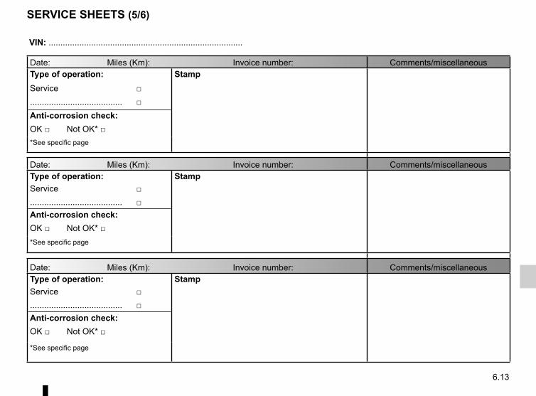
6.13
SERVICE SHEETS (5/6)
VIN: ..................................................................................
Date: Miles (Km): Invoice number: Comments/miscellaneousType of operation: StampService □....................................... □Anti-corrosion check:OK □ Not OK* □*See specific page
Date: Miles (Km): Invoice number: Comments/miscellaneousType of operation: StampService □....................................... □Anti-corrosion check:OK □ Not OK* □*See specific page
Date: Miles (Km): Invoice number: Comments/miscellaneousType of operation: StampService □....................................... □Anti-corrosion check:OK □ Not OK* □
*See specific page

6.14
VIN: ..................................................................................
Date: Miles (Km): Invoice number: Comments/miscellaneousType of operation: StampService □....................................... □Anti-corrosion check:OK □ Not OK* □*See specific page
Date: Miles (Km): Invoice number: Comments/miscellaneousType of operation: StampService □....................................... □Anti-corrosion check:OK □ Not OK* □*See specific page
Date: Miles (Km): Invoice number: Comments/miscellaneousType of operation: StampService □....................................... □Anti-corrosion check:OK □ Not OK* □
*See specific page
SERVICE SHEETS (6/6)

6.15
ANTICORROSION CHECK (1/5)
If the continuation of the warranty is subject to repair, it is indicated below.
VIN: ..........................................................
Corrosion repair operation to be carried out:
Stamp
Date of repair:
Repair to be carried out: Stamp
Date of repair:
Repair to be carried out: Stamp
Date of repair:

6.16
ANTICORROSION CHECK (2/5)
If the continuation of the warranty is subject to repair, it is indicated below.
VIN: ..........................................................
Corrosion repair operation to be carried out:
Stamp
Date of repair:
Repair to be carried out: Stamp
Date of repair:
Repair to be carried out: Stamp
Date of repair:

6.17
ANTICORROSION CHECK (3/5)
If the continuation of the warranty is subject to repair, it is indicated below.
VIN: ..........................................................
Corrosion repair operation to be carried out:
Stamp
Date of repair:
Repair to be carried out: Stamp
Date of repair:
Repair to be carried out: Stamp
Date of repair:

6.18
ANTICORROSION CHECK (4/5)
If the continuation of the warranty is subject to repair, it is indicated below.
VIN: ..........................................................
Corrosion repair operation to be carried out:
Stamp
Date of repair:
Repair to be carried out: Stamp
Date of repair:
Repair to be carried out: Stamp
Date of repair:
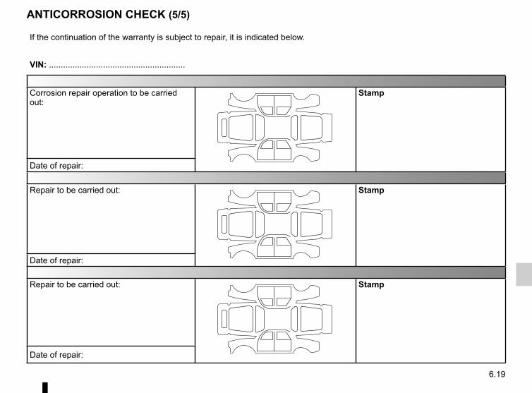
6.19
ANTICORROSION CHECK (5/5)
If the continuation of the warranty is subject to repair, it is indicated below.
VIN: ..........................................................
Corrosion repair operation to be carried out:
Stamp
Date of repair:
Repair to be carried out: Stamp
Date of repair:
Repair to be carried out: Stamp
Date of repair:

6.20

7.1
ALPHABETICAL INDEX (1/5)AABS .......................................................................2.34 → 2.37accessories........................................................................ 5.44accessories socket ............................................................ 3.14adjusting your driving position ...............................1.13 → 1.16advice on antipollution ....................................................... 2.20air bag....................................................................1.17 → 1.21
deactivating the front passenger air bags .................... 1.33air conditioning ..........................................................3.2 → 3.7air vents ...................................................................... 3.2 – 3.3anti-corrosion check ..............................................6.15 → 6.19anti-corrosion protection .................................................... 4.16anti-lock braking system: ABS ...............................2.34 → 2.37antipollution
advice .......................................................................... 2.20armrest .............................................................................. 3.19ashtrays ............................................................................. 3.14automatic gearbox (use) ...............................2.45 → 2.48, 5.42automatic gearbox selector lever...........................2.45 → 2.48
Bbattery..................................................................... 4.14 – 4.15
troubleshooting ................................................. 5.36 – 5.37battery (remote control) ..................................................... 5.38bonnet......................................................................... 4.2 – 4.3brake fluid ............................................................................ 4.8bulbs
changing ..........................................................5.16 → 5.27
Ccapacity of mechanical components........................... 4.4, 4.14catalytic converter.............................................................. 2.10central door locking .................................................... 1.5 – 1.6changing a bulb .....................................................5.16 → 5.27changing a wheel.................................................... 5.10 – 5.11changing fuel while driving ....................................2.12 → 2.14
changing gear ...............................................2.29, 2.45 → 2.48child booster seat ..................................................1.22 → 1.24child restraint/seat .................................................1.22 → 1.32child safety..................1.2, 1.8 – 1.9, 1.22 → 1.32, 3.8 → 3.10child seats..............................................................1.22 → 1.32children ....................................................... 1.5 – 1.6, 1.8 – 1.9children (safety) .......................................................3.8 → 3.10cigar lighter ........................................................................ 3.14cleaning:
inside the vehicle .............................................. 4.18 – 4.19clock .................................................................................. 1.57closing the doors ........................................................ 1.8 – 1.9control instruments ............................1.41 → 1.55, 1.59 – 1.60controls ..................................................................1.37 → 1.40courtesy light .......................................................... 3.11 – 3.12cruise control .........................................................2.41 → 2.44cruise control-speed limiter....................................2.38 → 2.44
Ddashboard..............................................................1.37 → 1.40dimensions .......................................................................... 6.5dipstick................................................................................. 4.4doors..........................................................................1.5 → 1.9driver’s position .....................................................1.37 → 1.40driving .........2.2 → 2.6, 2.10 – 2.11, 2.15 → 2.19, 2.29 → 2.50
EECO driving .....................................1.41 → 1.47, 2.15 → 2.19electric beam height adjustment ............................. 1.61 – 1.62electric door locking .................................................... 1.5 – 1.6electric windows ......................................................3.8 → 3.10electronic stability control: ESC .............................2.34 → 2.37emergency brake assist.........................................2.34 → 2.37emergency braking ................................................2.34 → 2.37emergency spare wheel ........................5.3 – 5.4, 5.12 → 5.15
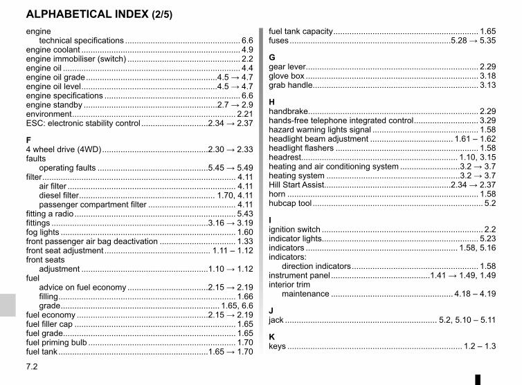
7.2
ALPHABETICAL INDEX (2/5)engine
technical specifications .................................................. 6.6engine coolant ..................................................................... 4.9engine immobiliser (switch) ................................................. 2.2engine oil ............................................................................. 4.4engine oil grade .........................................................4.5 → 4.7engine oil level ...........................................................4.5 → 4.7engine specifications ........................................................... 6.6engine standby ..........................................................2.7 → 2.9environment ....................................................................... 2.21ESC: electronic stability control .............................2.34 → 2.37
F4 wheel drive (4WD) ..............................................2.30 → 2.33faults
operating faults ................................................5.45 → 5.49filter .................................................................................... 4.11
air filter ......................................................................... 4.11diesel filter ........................................................... 1.70, 4.11passenger compartment filter ...................................... 4.11
fitting a radio ...................................................................... 5.43fittings ....................................................................3.16 → 3.19fog lights ............................................................................ 1.60front passenger air bag deactivation ................................. 1.33front seat adjustment .............................................. 1.11 – 1.12front seats
adjustment .......................................................1.10 → 1.12fuel
advice on fuel economy ...................................2.15 → 2.19filling ............................................................................. 1.66grade ..................................................................... 1.65, 6.6
fuel economy .........................................................2.15 → 2.19fuel filler cap ...................................................................... 1.65fuel grade........................................................................... 1.65fuel priming bulb ................................................................ 1.70fuel tank .................................................................1.65 → 1.70
fuel tank capacity ............................................................... 1.65fuses ......................................................................5.28 → 5.35
Ggear lever........................................................................... 2.29glove box ........................................................................... 3.18grab handle........................................................................ 3.13
Hhandbrake.......................................................................... 2.29hands-free telephone integrated control ............................ 3.29hazard warning lights signal .............................................. 1.58headlight beam adjustment .................................... 1.61 – 1.62headlight flashers .............................................................. 1.58headrest.................................................................... 1.10, 3.15heating and air conditioning system ..........................3.2 → 3.7heating system ..........................................................3.2 → 3.7Hill Start Assist.......................................................2.34 → 2.37horn ................................................................................... 1.58hubcap tool .......................................................................... 5.2
Iignition switch ...................................................................... 2.2indicator lights.................................................................... 5.23indicators .................................................................. 1.58, 5.16indicators:
direction indicators ....................................................... 1.58instrument panel ...........................................1.41 → 1.49, 1.49interior trim
maintenance ..................................................... 4.18 – 4.19
Jjack .................................................................. 5.2, 5.10 – 5.11
Kkeys ............................................................................ 1.2 – 1.3

7.3
ALPHABETICAL INDEX (3/5)Llevels ................................................................4.4, 4.8 → 4.10levels:
coolant ........................................................................... 4.9windscreen washer reservoir ....................................... 4.10
lifting the vehiclechanging a wheel ...............................5.2 – 5.4, 5.9 → 5.11
lighting:exterior .........................................1.59 – 1.60, 5.16 → 5.23interior ..........................................3.11 – 3.12, 5.24 → 5.27
lights ......................................................................1.59 → 1.62additional ..................................................................... 5.17adjustment ........................................................ 1.61 – 1.62
lights:adjusting ........................................................... 1.61 – 1.62brake lights .................................................................. 5.18daytime running lights .................................................. 5.16dipped beam headlights ...................................... 1.59, 5.16direction indicators .............................................. 1.58, 5.16fog lights ............................................................. 1.60, 5.17hazard warning ............................................................ 1.58main beam headlights ......................................... 1.59, 5.16reversing lights ............................................................. 5.18side lights ............................................................ 1.59, 5.16
locking the doors ................................................................. 1.4LPG .............1.68 – 1.69, 2.3, 2.12 → 2.14, 3.26, 5.28 → 5.35
Mmaintenance ...................................................................... 2.20maintenance:
bodywork .......................................................... 4.16 – 4.17interior trim ........................................................ 4.18 – 4.19mechanical ..................................4.4, 4.8, 4.14, 6.9 → 6.14
map reading lights .................................................. 3.11 – 3.12methods of restraint in addition to the front seat belts ..............1.17 → 1.19, 1.21
mirrors ............................................................................... 3.13multimedia equipment ....................................................... 3.29
Nnavigation .......................................................................... 3.29navigation system .............................................................. 3.29
Ooil change ..................................................................4.5 → 4.7opening the doors ....................................................... 1.8 – 1.9operating faults ......................................................5.45 → 5.49overspeed buzzer ................................................... 1.48 – 1.49
Ppaintwork
maintenance ..................................................... 4.16 – 4.17reference ........................................................................ 6.2
parking distance control.........................................2.49 → 2.52power-assisted steering............................................ 1.56, 4.10power-assisted steering pump........................................... 4.10practical advice .....................1.70, 3.26, 5.2 – 5.4, 5.9 → 5.37, 5.39 → 5.43, 5.45 → 5.49puncture.................................................. 5.3 – 5.4, 5.10 – 5.11
Rradio................................................................................... 3.29
fitting a radio ................................................................ 5.43radio frequency remote control/key
use ................................................................................. 1.2rear bench seat......................................................3.20 → 3.22rear parcel shelf ................................................................. 3.27rear screen de-icing/demisting ..................................3.4 → 3.6rear seats
functions ..........................................................3.20 → 3.22rear view camera .................................................... 2.51 – 2.52rear view mirrors ................................................................ 1.36

7.4
ALPHABETICAL INDEX (4/5)remote control door locking
batteries ....................................................................... 5.38remote control door locking unit ................................1.2 → 1.4remote engine start-up ............................................... 1.2 – 1.3RENAULT ANTI-INTRUDER DEVICE (RAID) ..................... 1.7replacement parts ................................................................ 6.8reverse gear
selecting ....................................................................... 2.29reversing sensor ..................................................... 2.49 – 2.50roof bars ............................................................................ 3.28roof rack
roof bars ....................................................................... 3.28running in ............................................................................. 2.2
Sseat belts ...............................................................1.13 → 1.21service sheets..........................................................6.9 → 6.14signals and lights .................................................... 1.59 – 1.60speakers
location ........................................................................ 5.43special features of diesel versions..................................... 2.11special features of LPG versions .....2.12 → 2.14, 5.28 → 5.35special features of petrol vehicles ..................................... 2.10speed limiter ..........................................................2.38 → 2.40starting .......................................................................2.3 → 2.6starting the engine .....................................................2.2 → 2.9steering wheel
adjustment ................................................................... 1.56Stop & Start ...............................................................2.7 → 2.9Stop & Start function..................................................2.7 → 2.9storage compartment.............................................3.16 → 3.19storage compartments ...........................................3.16 → 3.19sun visor ............................................................................ 3.13
Ttailgate ...................................................................3.23 → 3.25
tanks and reservoirsbrake fluid ...................................................................... 4.8coolant ........................................................................... 4.9
tanks and reservoirs:windscreen washer ...................................................... 4.10
technical specifications .......................................6.2, 6.6 → 6.8telephone ........................................................................... 3.29towing .................................................................................. 6.7
breakdown .......................................................5.40 → 5.42towing equipment ......................................................... 3.26
towing a caravan ................................................................. 6.7towing hitch............................................................5.40 → 5.42towing rings ............................................................ 3.24 – 3.25towing weights ..................................................................... 6.7traction control .......................................................2.34 → 2.37transporting children ..............................................1.22 → 1.32transporting objects
in the luggage compartment ............................. 3.24 – 3.25trims ..................................................................................... 5.9trip computer and warning system.........................1.50 → 1.55tyre inflation kit...........................................................5.5 → 5.8tyre pressure.............................2.22 → 2.28, 4.12 – 4.13, 5.13tyre pressure loss warning.....................................2.22 → 2.28tyre pressures ......................................................... 4.12 – 4.13tyres .............................2.22 → 2.28, 4.12 – 4.13, 5.12 → 5.15
Vvariable power-assisted steering ....................................... 1.56vehicle identification ............................................................ 6.2vehicle identification plates ........................................6.2 → 6.4ventilation
air conditioning ...................................................... 3.2 – 3.3heating and air conditioning system ....................3.4 → 3.7
Wwarning buzzer .................................................................. 1.60

7.5
ALPHABETICAL INDEX (5/5)warning lights.........................................................1.41 → 1.55washing .................................................................. 4.16 – 4.17weight .................................................................................. 6.7weights ................................................................................ 6.7wheelbrace .......................................................................... 5.2windows ...................................................................3.8 → 3.10windscreen washer ........................................ 1.63 – 1.64, 4.10wiper blades ...................................................................... 5.39wipers ..................................................................... 1.63 – 1.64
blades .......................................................................... 5.39

7.6


RENAULT S.A.S. SOCIÉTÉ PAR ACTIONS SIMPLIFIÉE AU CAPITAL DE 533 941 113 € / 13-15, QUAI LE GALLO92100 BOULOGNE-BILLANCOURT R.C.S. NANTERRE 780 129 987 — SIRET 780 129 987 03591 / TÉL. : 0810 40 50 60
NU 1079-7 – 99 91 028 25R – 10/2015 – Edition anglaise
à999102825Rêïìä X7