Embed Size (px)
Citation preview

Slide 1
<Insert Picture Here>
Oracle

Slide 2
<Insert Picture Here>
WZT-6509 version B
Sun Fire Nehalem and Westmere Rack-Mount Server
Installation and Replacement
Welcome to the installation and replacement module. This content will cover the installation and replacement procedures of the X2270, X4170, X4270 and X4275 rack-mount servers and their M2 models.

Slide 3
3
Objectives
• Prepare the server for installation
• Prepare the server for component replacement
• Name the key steps of replacing the server or its
components
Upon completion of this module, you should be able to:
1Prepare the server for installation
2Prepare the server for component replacement and
3Name the key steps of replacing the server or its components

Slide 4
4
Additional Resources
• Sun Microsystems, Inc., Sun Fire X2270 Server Service Manual ,
Revision A, March 2009 Part Number 820-5607-xx.
• Sun Microsystems, Inc., Sun Fire X4170, X4270 and X4275 Servers
Service Manual , Revision A, March 2009 Part Number 820-5830-xx.
• Sun Microsystems, Inc., Sun Fire X4170, X4270 and X4275 Servers
Installation Guide, Revision A, March 2009, Part Number 820-5827-xx.
• Sun Microsystems, Inc., Sun Fire X4170, X4270 and X4275 Servers
Solaris and Linux OS Installation Guide, Revision A, March 2009, Part
Number 820-5828-xx.
• Sun Microsystems, Inc., Sun Fire X4170, X4270 and X4275 Servers
Windows OS Installation Guide, Revision A, March 2009, Part Number
820-5829-xx.
Press PLAY (4) to Continue
The following references provide additional information on the servers and their components.1

Slide 5
5
Additional Resources
• Sun Microsystems, Inc., Sun Fire X2270 M2 Server Service Manual,
Revision A, April 2010, Part Number 821-1345-xx.
• Sun Microsystems, Inc., Sun Fire X4170 M2 Servers Service Manual,
Revision A, April 2010, Part Number 821-0486-xx.
• Sun Microsystems, Inc., Sun Fire X4270 M2 Servers Service Manual,
Revision A, April 2010, Part Number 821-0488-xx
• Sun Microsystems, Inc., Sun Fire X4170 and X4270 M2 Servers
Installation Guide, Revision A, April 2010, Part Number 821-0481-xx
• Sun Microsystems, Inc., Oracle Integrated Lights Out Manager (ILOM)
3.0 Supplement for Sun Fire X4170 M2 and X4270 M2 Servers,
Revision A, April 2010, Part Number 821-0489-xx
• http://panacea.central.sun.com/twiki/bin/view/WebHome
Press PLAY (4) to Continue
The following references provide additional information on the M2 servers and their components 1along
with the links to the TOI presentations that served as the source information for this module.2

Slide 6
6
Rack Mount Server Configurations
Sun Fire X4170 and X4170 M2Server
1U
Sun Fire X4270 and X4270 M2Server
2U
Sun Fire X4275 and X4275 M2 Server
2U
Sun Fire X2270 and X2270 M2Server
1U
Press PLAY (4) to Continue
This presentation will cover the installation and replacement procedures for the rack mount servers displayed here and their replaceable components. Any procedures that apply to a specific model or models will be noted in the presentation.
1

Slide 7
7
Rack Mounting the Server
Rack mount server
Rack mount Kit
Getting Started
Documentation
Dongle cable
and adapter
Key installation steps:
Step 1: Inventory the components
Press PLAY (4) to Continue
Once you unpack the rack mount server, do an inventory to verify you have all the components listed here before you start any other tasks.
1
Slide 8
8
Rack Mounting the Server
Key installation steps:
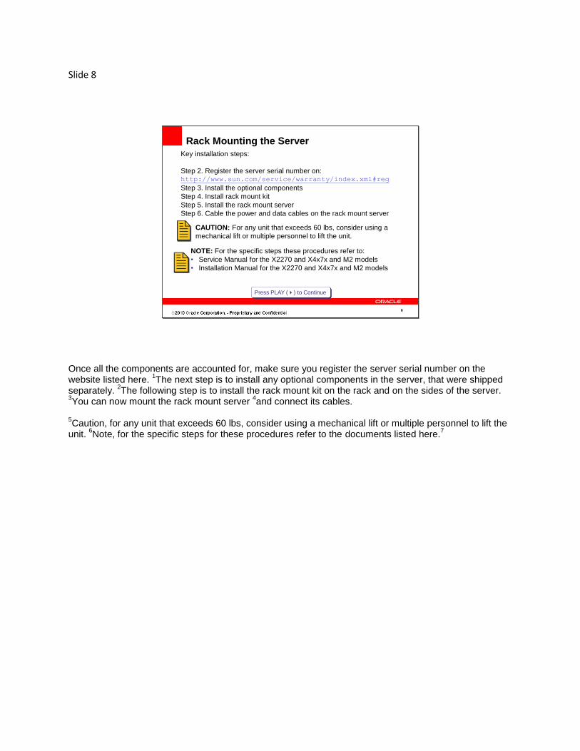
Step 2. Register the server serial number on:http://www.sun.com/service/warranty/index.xml#reg
Step 3. Install the optional components
Step 4. Install rack mount kit
Step 5. Install the rack mount server
Step 6. Cable the power and data cables on the rack mount server
Press PLAY (4) to Continue
NOTE: For the specific steps these procedures refer to:
• Service Manual for the X2270 and X4x7x and M2 models
• Installation Manual for the X2270 and X4x7x and M2 models
CAUTION: For any unit that exceeds 60 lbs, consider using a
mechanical lift or multiple personnel to lift the unit.
Once all the components are accounted for, make sure you register the server serial number on the website listed here.
1The next step is to install any optional components in the server, that were shipped
separately. 2The following step is to install the rack mount kit on the rack and on the sides of the server.
3You can now mount the rack mount server
4and connect its cables.
5Caution, for any unit that exceeds 60 lbs, consider using a mechanical lift or multiple personnel to lift the
unit. 6Note, for the specific steps for these procedures refer to the documents listed here.
7

Slide 9
9
Replacing the HDDs and SSDs (X2270/X2270 M2)
If you are replacing an hard disk drive on the X2270 or X2270 M2 server all you need to do is 1to push on
the HDD handle button to pop out the handle then use the handle to pull the HDD out of its slot. 2To install a replacement HDD, just slide the HDD into the open slot until it engages the disk backplane
connector then secure the it to the slot by locking the handle against the front faceplate of the HDD.

Slide 10
10
Replacing the HDDs and SSDs (X4x7x/X4x7x M2)
NOTE: This procedure is the same on any HDD or SSD
on a X4170, X4270 or X4275 server or its M2 models
Press PLAY (4) to Continue
On the X4170, X4270 and X4275 servers and the M2 models, after identifying the HDD or SSD to replace, 1push on the disk handle button to pop the handle
2and use the handle to remove the drive.
3Following the
opposite procedure, install the replacement disk and finish the installation by locking the disk drive handle against the drive. 4Note, this procedure is the same on any HDD or SSD on these servers. Click on the attachment tab and
select HDD Configurations Rules Table for these servers.6

Slide 11
11
Replacing the Power Supplies (X4x7x/X4x7x M2)
Can be
HOT SWAPPED
X427x / X427x M2X4170 / X4170 M2
The power supplies of all the servers, except for the X2270 and X2270 M2, can be hot swapped without disturbing the operation of the server if the redundant power supply is functioning.
1The power supplies
support a green Power OK LED, an amber Service Action Required LED and a green AC OK LED from top to bottom on the X4270, X4275 servers and their M2 models.
2The X4170 and X4170 M2 servers
have the same LEDs arranged in the opposite direction, from bottom to top. 3To remove X4170 power supply you first need to release the cable management arm, if present. Then
make sure that the redundant power supply is functional before unlatching and pulling the failed power supply out of its slot using its front handle.
4The X4270 server has a sight difference in the handle lock, as
you can see. 5To replace the power supply, slide the replacement power supply into the open slot until it engages its
slot connector and is flush with the chassis. Remember to re-engage the cable management arm.

Slide 12
12
Replacing Server Top Cover (X2270 / X2270 M2)
NOTE: Before handling any of the internal
components make sure that have an anti-
static strap on for proper grounding.
After removing the X2270 or X2270 M2 server from the rack and placing it on an anti-static mat, you need to remove its top cover to access the internal components. To remove the top cover loosen the holding screw then just lift off its cover vertically. 1Note, before handling any of the internal components, make sure that have an anti-static strap on for
proper grounding.

Slide 13
13
Replacing Server Top Cover (X4170 / X4170 M2)
NOTE: Before handling any of the internal components make
sure that have an anti-static strap on for proper grounding.
After removing the X4170 or the X4170 M2 server from the rack and placing it on an anti-static mat, you need to remove its top cover to access its internal components. To remove the top cover
1you need to
unlatch the fan module door, 2press the top cover release button
3then lift the cover vertically off the
server. 4Note, before handling any of the internal components make sure that have an anti-static strap on for
proper grounding.

Slide 14
14
Replacing Server Top Cover (X427x / X427x M2)
NOTE: Before handling any of the internal components make
sure that have an anti-static strap on for proper grounding.
After removing the X4270 or X4275 server or an M2 model from the rack and placing it on an anti-static mat, you need to remove its top cover to access its internal components. To remove the top cover
1you
need to unlatch the fan module door, 2release the top cover by moving the green latch to the leftmost
position 3then slide the cover to the back of the server
4and lift the cover vertically off the server.
5Note, before handling any of the internal components make sure that have an anti-static strap on for
proper grounding.

Slide 15
15
Replacing the Power Supply (X2270 / X2270 M2)
The replacement of the X2270 and X2270 M2 server power supply requires the server powered down, removed from its slot and placed on an anti-static mat with its cover removed. The power supply removal process requires
1the three power supply cables disconnected from the motherboard, with the disk drive
power cable disconnected and threaded out of the chassis metal cutout. 2Then with the removal of the
mounting screw, you can lift the power supply out of the chassis. 3The installation of the replacement power supply uses the opposite procedure making sure that all three
cables are routed and connected properly and that the mounting screw is replaced.

Slide 16
16
Replacing the Blowers (X2270 / X2270 M2)
The blowers on the X2270 and X2270 M2 servers can be replaced 1by simply disconnecting the power
cable 2and lifting the blower vertically our of the chassis while making sure that the cable does not get
caught within the chassis metal cutout. 3To replace the blower just thread the replacement’s cable through the metal cutout on the chassis,
connect the power cable and then install the blower in the open slot.

Slide 17
17
Replacing the Fan Module (X4170 / X4170 M2)
X4170 X4170 M2
Each fan module on the X4170 server has two LEDs located on top of each fan module. 1One amber
Service Action Required LED that lights when either of the fan pair have failed and one green Power OK LED that is lit when the fans are operating correctly. The X4170 M2 server, on the other hand,
2has one
bi-color LED that can display either an amber or green color. 3In either case, to replace the fan module just lift the fan module vertically out of its slot. Note, X4170 M2
server has a latch that you need to release. 4To install a replacement just slide a replacement module
vertically into the open slot.

Slide 18
18
Replacing the Fans (X427x / X427x M2)
X4270 M2X4270
Each fan module on the X4270 and X4275 servers have two LEDs located on top of each fan module. 1One amber Service Action Required LED that lights when either of the fan pair have failed and one
green Power OK LED that is lit when the fans are operating correctly. The X4270 M2 and X4275 M2 servers, on the other hand,
2have one bi-color LED per fan model that can display either an amber or
green color. These LEDs are located on the edge of the chassis as you see here. 3In either case, to remove the fan module just lift the fan module vertically out of its slot.
4To install a
replacement just slide a replacement module vertically into the open slot.

Slide 19
19
Replacing the Air Duct (X2270 / X2270 M2)
The X2270 and X2270 M2 servers have an air duct that routes the cool air over the CPUs and DIMMs and out the rear of the server. This air duct can be removed by lifting it off the motherboard to access the components like the CPUs and DIMMs that are underneath.
1Replacement is just as easy, just lay it back
on the motherboard as you see here.

Slide 20
20
Replacing the Air Baffle (X427x)
NOTE: The X4270 M2 and X4275 M2 do not have
air baffles.
The X4270 and X4275 servers have an air baffle that routes the cool air over the CPUs and DIMMs and out the rear of the server blade.
1This air baffle can be removed by pressing the air baffle connectors
outward and lifting it off the motherboard to access the components like the CPUs and DIMMs that are underneath. Replacement is just as easy, just engage it to the motherboard as you see here.
2Note, the
X4270 M2 and X4275 M2 do not have air baffles.

Slide 21
21
Locations of Memory DIMMs (X2270 / X2270 M2)
NOTE: There is no fault remind button on the X2270 or X2270 M2 server
and the DIMM and CPU amber fault LEDs are controlled by ILOM.
CPU1
CPU0
After removing the top cover of the X2270 or X2270 M2 server blade, you can see 6 memory DIMM slots associated with each CPU. A failed DIMM may be identified within an error message which contains a CPU and DIMM slot number. Notice that DIMM slot D0 is closest to the CPU it corresponds to. 1Note, there is no fault remind button on the X2270 or X2270 M2 server and the DIMM and CPU amber
fault LEDs are controlled by ILOM.

Slide 22
22
Locations of Memory DIMMs (X4x7x / X4x7x M2)
NOTE: DIMM slot D0 is closest to the CPU it corresponds to and
that each set of 3 DIMM slots corresponds to memory channel.
0 1 22 1 0
After removing the top cover of the X4170, X4270 or X4275 server or any of the M2 models, you can see 9 memory DIMM slots associated with each CPU. A failed DIMM may be identified within an error message by the CPU and DIMM slot number or by pressing the fault remind button to see which DIMM fault LED displays.
1Note, DIMM slot D0 is closest to the CPU it corresponds to and each set of 3 DIMM
slots corresponds to memory channel.

Slide 23
23
Replacing a Memory DIMM (X2270 / X2270 M2)
CPU1CPU0
Press PLAY (4) to Continue
CPU1CPU0
When you go to replace a failed DIMM or add new DIMMs, make sure you follow the DIMM population rules to avoid configuring the memory incorrectly and to maintain the highest possible performance. Once this slide completes, select the X2270 DIMM Population Rules entry on the attachments tab to view the correct method of populating the memory. 1To remove a DIMM push down on the two side handles to disengage the DIMM then lift it out of its
socket. 2Reverse the process to install a replacement DIMM making sure the side handles lock the DIMM
into the socket.3

Slide 24
24
Replacing a Memory DIMM (X4x7x / X4x7x M2)
Press PLAY (4) to Continue
On the X4170, X4270, X4275 servers or any of the M2 models, when you go to replace the failed DIMM or add new DIMMs, make sure you follow the DIMM population rules to avoid configuring the memory incorrectly and to maintain the highest possible performance. Once this slide completes, select X4x7x DIMM Population Rules entry to view the correct method of populating the memory. 1To remove a DIMM push down on the two side handles to disengage the DIMM then lift it out of its
socket. 2Reverse the process to install a replacement DIMM making sure the side handles lock the DIMM
into the socket.3
Slide 25
25
Replacing a CPU (X2270, X4x7x and M2 models)
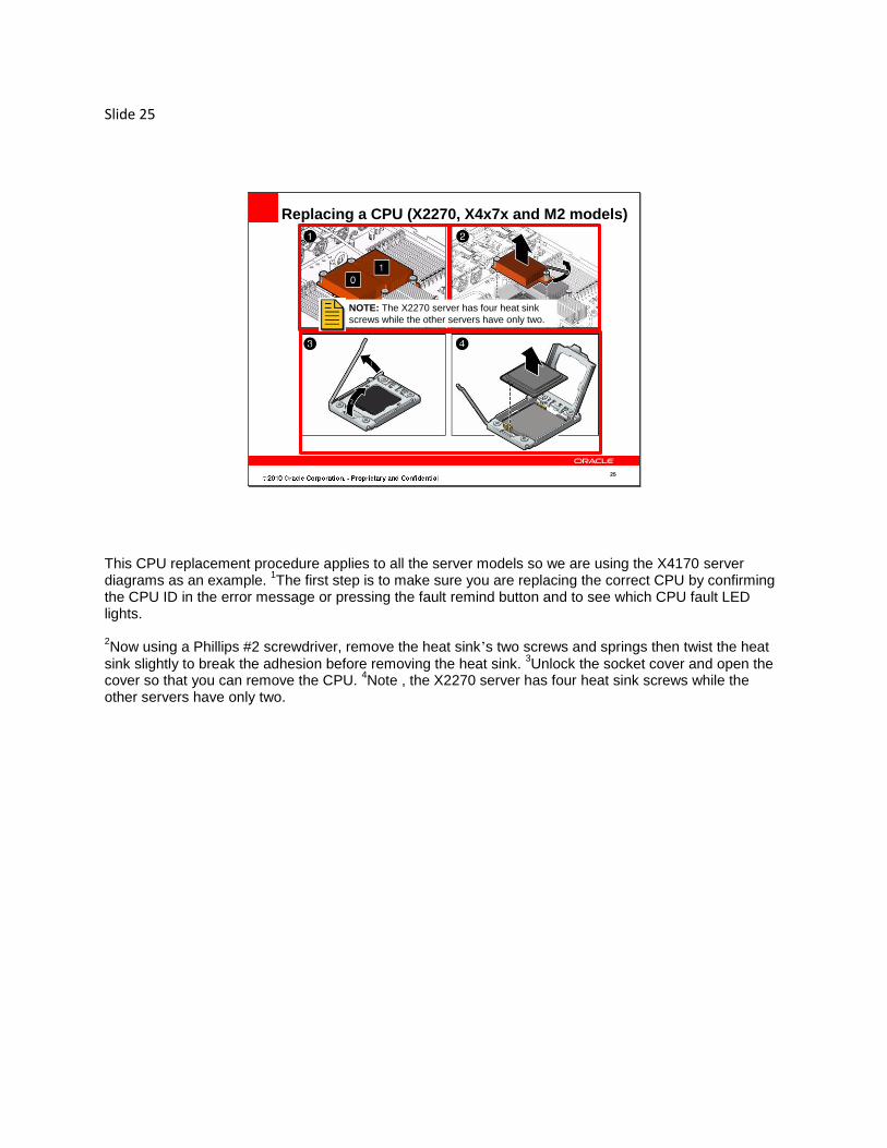
NOTE: The X2270 server has four heat sink
screws while the other servers have only two.
This CPU replacement procedure applies to all the server models so we are using the X4170 server diagrams as an example.
1The first step is to make sure you are replacing the correct CPU by confirming
the CPU ID in the error message or pressing the fault remind button and to see which CPU fault LED lights. 2Now using a Phillips #2 screwdriver, remove the heat sink’s two screws and springs then twist the heat
sink slightly to break the adhesion before removing the heat sink. 3Unlock the socket cover and open the
cover so that you can remove the CPU. 4Note , the X2270 server has four heat sink screws while the
other servers have only two.

Slide 26
26
Replacing a CPU (X2270, X4x7x and M2 models)
Now, align and install the replacement CPU in the socket, then install the CPU in the socket 1and secure
it by closing the socket cover over the CPU and locking it using the socket lever. Remember to apply the thermal grease in as an X on top of the CPU before
2you replace the heat sink and tighten the heat sink
screws.

Slide 27
27
Replacing the SP Module (X2270 and X2270 M2)
The service processor module is an optional card, on the X2270 and X2270 M2 servers, that contains the server management hardware and software. To access the card, the air duct needs to be removed from the chassis and SP cables need to disconnected from the SP card. 1To remove the SP card, loosen the holding screw
2then disengage its motherboard connector by lifting
the card up. Make sure to slide the card forward before lifting it out of the chassis. 3To install the SP card, first install the alignment pin on the screw hole then install the card, making sure
that the card’s connectors are oriented towards the rear chassis openings. Finally, secure the card by tightening the holding screw.

Slide 28
28
Replacing the RTC Battery (X2270, X4x7x and M2 models)
X2270 X2270 M2
X4x7x and
X4x7x M2
CR2032
CR2032
CR2032
Every server covered in this presentation has a real time clock that is used to maintain the system clock running when the server is not powered. The differences are in the location of the RTC battery and whether the battery stands vertically or lays flat on the motherboard. 1The vertical real time clock battery can be removed by pushing the disc away from the socket wall and
against the metal lead then lifting it vertically out of the socket. 2The horizontal real time clock battery can
be removed by pulling then quickly releasing the battery retaining click to pop the battery out if its socket, then just lift the battery out of the socket.
3The installation of the RTC battery is performed by orienting the
disc’s positive side away from the socket back wall while the disc is slid vertically or placed horizontally into the socket, depending on the socket type.

Slide 29
29
Replacing the PCIe Riser (X2270 / X2270 M2)
On the X2270 and X2270 M2 server, the PCIe riser card plugs into a motherboard connector. To remove the riser card, assuming there is no PCIe board installed, all you need to do is pull the riser card vertically out of the motherboard socket.
1To install a replacement riser card plug the riser card into the
motherboard socket.

Slide 30
30
Replacing the PCIe Riser (X4170 / X4170 M2)
There are 3 single slot riser cards on the X4170 and X4170 M2 servers so their replacement is different than the dual slot riser cards on the X4270 and X4275 servers and their M2 models. To replace a PCIe riser card, assuming the server blade is already on an anti-static mat with its cover off,
1you need to
loosen the two captive screws of the back panel crossbar 2then lift it out of the chassis.
3Now, disconnect any internal cables to the PCIe board, if present, disengage the PCIe card from the
riser and lift it out of the chassis. 4Now, loosen the riser card’s holding screw, disengage the riser card
and lift it of the chassis. 5The installation of a replacement riser card follows the reverse of this procedure
making sure the riser card is properly secured by tightening the holding screw and returning the PCIe card to the riser, if one was present.

Slide 31
31
Replacing the PCIe Riser (X427x / X427x M2)
The riser cards on the X4270 and X4275 server and the M2 models are dual slot riser cards. Before removing the PCIe riser card, the server needs to be powered off and on an anti-static mat with its cover removed. 1Once inside the chassis make sure that all internal cables to the riser card or its PCIe boards are
disconnected. Now remove the 2 captive Phillips screws on the ends of the PCI crossbar and lift the crossbar out of the chassis.
2Remove the captive Phillips screws that holds the riser card to the
motherboard. You can now remove the riser card from the motherboard. 3To install a replacement riser card, install the riser card on the motherboard connector and secure it with
Phillips screws. 4Now install the crossbar and secure it with two screws on the ends of the crossbar.
Slide 32
32
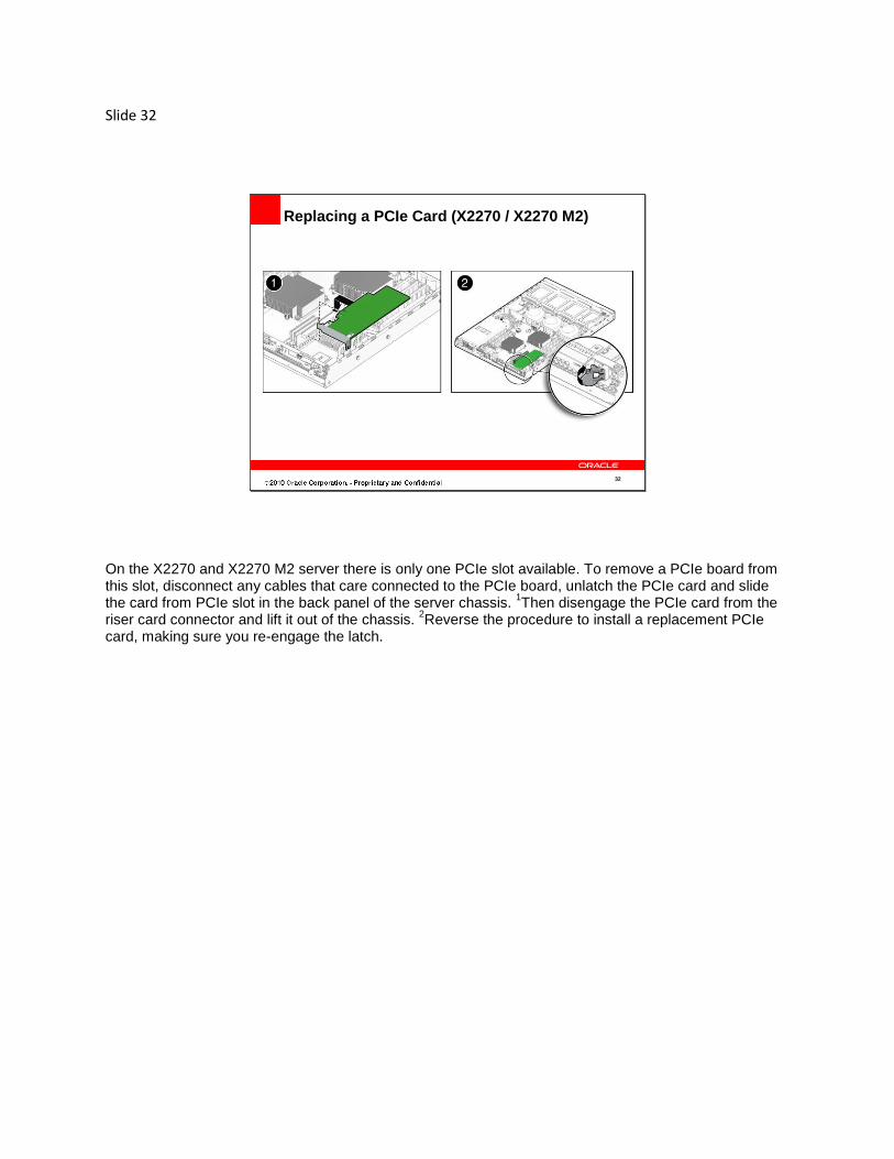
Replacing a PCIe Card (X2270 / X2270 M2)
On the X2270 and X2270 M2 server there is only one PCIe slot available. To remove a PCIe board from this slot, disconnect any cables that care connected to the PCIe board, unlatch the PCIe card and slide the card from PCIe slot in the back panel of the server chassis.
1Then disengage the PCIe card from the
riser card connector and lift it out of the chassis. 2Reverse the procedure to install a replacement PCIe
card, making sure you re-engage the latch.

Slide 33
33
Replacing a PCIe Card (X4170 / X4170 M2)
The PCIe cards on the X4170 and X4170 M2 servers can be installed into three possible PCIe slots off of 3 separate riser cards.
1First, unplug all cables connected to the PCIe card. Then loosen the Phillips
screws to the riser card and lift the riser card along with the PCIe card off the chassis. 2Now disengage
the PCIe card from the riser card. To install a replacement PCIe board, just reverse the procedure.
3If no PCIe board replacement will be
performed make sure to install a filler panel in the open chassis slot.

Slide 34
34
Replacing a PCIe Card (X4270 / X4270 M2)
22
2
The PCIe cards on the X4270 and X4275 servers and the M2 models can be installed into six possible PCIe slots off of three dual slot riser cards.
1First, unplug all cables connected to the PCIe card, then
remove the two Phillips screws to the PCI crossbar and lift the crossbar out of the chassis. 2Now, loosen
the captive screw on the riser card and lift the riser card and PCIe card out of the chassis. 3Finally,
disengage the PCIe card from the riser card. To install a replacement PCIe board, just reverse the procedure.
4If no PCIe board replacement will be
performed make sure to install a filler panel in the open chassis slot.

Slide 35
35
Replacing the Front I/O Board (X2270 / X2270 M2)
The I/O board on the X2270 and X2270 M2 servers can be removed from its chassis by first removing the three screws securing the I/O board to the HDD cage then lifting the I/O board out of the chassis and disconnecting any cables attached to the I/O board. 1To install the replacement I/O board, connect the internal cables, slide the I/O board forward until the
front connectors are flush with their chassis cutout then align the I/O board screw holes with their corresponding standoffs. Finally, fasten the three screws to secure the I/O board.

Slide 36
36
Replacing the Disk Backplane (X2270 / X2270 M2)
NOTE: Record which drive slot each disk drive came out of.
The disk backplane on the X2270 and X2270 M2 servers can be replaced once its disks are removed. 1Note, make sure to record which drive slot each disk drive came out of.
2First, remove all power and data cables from the disk backplane,
3then remove the 8 Phillips screws that
fasten the disk backplane to the motherboard. You can now lift the disk backplane out of the chassis. 4Reverse this process to install a replacement disk backplane.

Slide 37
37
Remove:
• disks
• DVD
• storage drive cage
Replacing the Disk Backplane (X4170 / X4170 M2)
NOTE: Record which drive slot each disk drive came out of.
The disk backplane on the X4170 and X4170 M2 servers can be replaced once its disks, DVD and storage drive cage along with the disk backplane are removed from the chassis.
1Note, make sure to
record which drive slot each disk drive came out of. 2To separate the disk backplane from the storage drive cage, remove the two Phillips screws holding the
backplane to the cage then slide the disk backplane off the storage drive cage retention hooks. 3To install
a replacement disk backplane, reverse the procedure and reinstall the assembly in the chassis then return the disks and DVD.
Slide 38
38
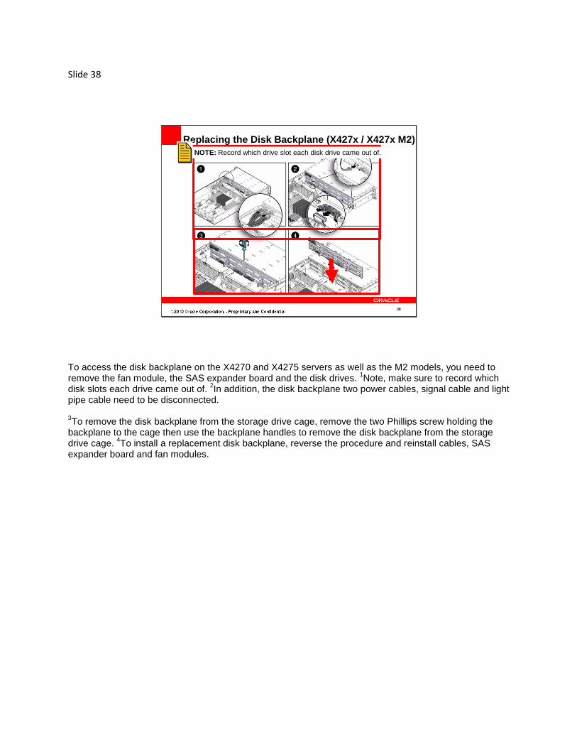
Replacing the Disk Backplane (X427x / X427x M2)
NOTE: Record which drive slot each disk drive came out of.
To access the disk backplane on the X4270 and X4275 servers as well as the M2 models, you need to remove the fan module, the SAS expander board and the disk drives.
1Note, make sure to record which
disk slots each drive came out of. 2In addition, the disk backplane two power cables, signal cable and light
pipe cable need to be disconnected. 3To remove the disk backplane from the storage drive cage, remove the two Phillips screw holding the
backplane to the cage then use the backplane handles to remove the disk backplane from the storage drive cage.
4To install a replacement disk backplane, reverse the procedure and reinstall cables, SAS
expander board and fan modules.

Slide 39
39
Replacing a Flash Module (X2270 / X2270 M2)
CAUTION: Do not attempt a replacement procedure while the flash module
green power LED, on the motherboard located next to the slot, is lit.
NOTE: The X2270 does not support FMODs but does support flash cards.
The X2270 and X2270 M2 servers have a pair of flash modules referred to as FMODs. 1Note, the X2270
does not support FMODs but does support flash cards. 2Caution, do not attempt a replacement procedure
while the flash module slot LED, located on the motherboard next to the slot, is lit. After the server is powered down it should take approximately 10 seconds for the flash module slot LED to turn off. 3To remove a flash module push down its two handles which will disengage the module from its socket
then lift it vertically out of its socket. 4To install a replacement flash module, seat the device in the socket
and push down on it until its handles lock it in.

Slide 40
40
Replacing a Flash Module (X4x7x / X4x7x M2)
CAUTION: Do not attempt a replacement procedure while the flash
module slot LED, on the motherboard located next to the slot, is lit.
The X4170, X4270 and X4275 servers and its M2 models have a pair of flash modules referred to as FMODs. To locate a failed FMOD press the fault remind button, then determine if the FMOD’s amber fault LED, pointed out by the white arrow, is lit.
1Caution, do not attempt a replacement procedure while the
flash module slot LED, located on the motherboard next to the slot, is lit. After a server is powered down it should take approximately 10 seconds for the flash module slot LED to turn off. 2To remove a flash module push down its two handles which will disengage the module from its socket
then lift it vertically out of its socket. 3To install a replacement flash module, seat the device in the socket
and push down on it until its handles lock it in.

Slide 41
41
Replacing an ESM and Riser (X4170 / X4170 M2)
The ESM and its riser, on the X4170 and X4170 M2 servers, are located 1between the DIMM slots and
the PCIe slots next to the power supplies. To remove the ESM and riser, 2remove the three Phillips
screws that secure the assembly to the motherboard then lift the assembly out of the chassis. To remove the ESM,
3disconnect the ESM power cable, lift off the ESM plastic case cover,
4then lift the ESM out of
its plastic casing. To install the ESM and its riser,
5just reverse the procedure making sure you
6secure it using the three
Phillips screws.

Slide 42
42
Replacing an ESM Riser (X427x / X427x M2)
The ESM and its riser, on the X4270 and X4275 servers and the M2 models, are located 1between the
DIMM slots and the PCIe slots next to the power supplies. To remove the ESM and riser, 2remove the
three Phillips screws that secure the assembly to the motherboard then lift the assembly out of the chassis. To remove the ESM,
3disconnect the ESM power cable, lift off the ESM plastic case cover,
4then
lift the ESM out of its plastic casing. To install the ESM and its riser,
5just reverse the procedure making sure you secure the ESM and its riser
using the three Phillips screws.
Slide 43
43
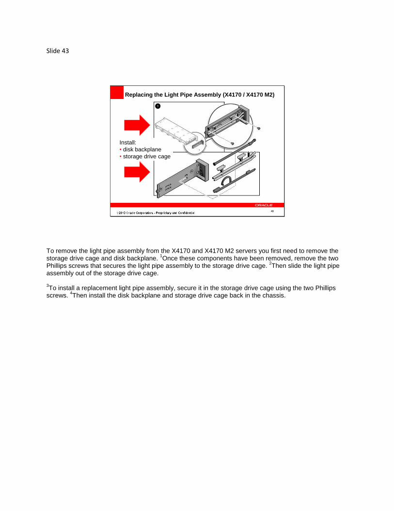
Replacing the Light Pipe Assembly (X4170 / X4170 M2)
Remove:
• storage drive cage
• disk backplane
Install:
• disk backplane
• storage drive cage
To remove the light pipe assembly from the X4170 and X4170 M2 servers you first need to remove the storage drive cage and disk backplane.
1Once these components have been removed, remove the two
Phillips screws that secures the light pipe assembly to the storage drive cage. 2Then slide the light pipe
assembly out of the storage drive cage. 3To install a replacement light pipe assembly, secure it in the storage drive cage using the two Phillips
screws. 4Then install the disk backplane and storage drive cage back in the chassis.

Slide 44
44
Replacing the Light Pipe Assembly (X427x / X427x M2)
The light pipe assembly on the X4270 and X4275 servers and the M2 models does not require the removal of any components prior to its removal.
1First, remove the Phillips screw that secures the light
pipe assembly to the server front panel. 2Then disconnect light pipe assembly cable from the disk
backplane and pull the cable gently through the side wall of the chassis. Now remove the light pipe assembly from the server front panel. To install a replacement light pipe assembly, reverse this procedure making sure
3you carefully pull the
assembly’s cable through the chassis side wall 4and secure the assembly using the Phillips screw.

Slide 45
45
Replacing the Paddle Board (X4170 / X4170 M2)
Remove:
• motherboard
• disk backplane
Install:
• disk backplane
• motherboard
The paddle board, on the X4170 and X4170 M2 servers, is an infrastructure board that is powered once AC power is applied to the server.
1To access the paddle board, remove the motherboard, the power
distribution board and the fan module next to the paddle board. Start the paddle board removal
2by disconnecting its fan power and signal cables. Remove the two
screws holding the board and its support bracket to the chassis mid wall. 3Slide the assembly towards the
rear of the chassis to disengage the paddle board edge connector from the disk backplane and lift it out of the chassis. To separate the paddle board from the support bracket, remove its two supporting screws. 4To install a replacement paddle board, connect the paddle board to its support bracket using the two
Phillips screws, install the assembly into the chassis, connect the fan power and signal cables and secure the assembly using the other two Phillips screws.
5You can now reinstall the disk backplane and
motherboard.

Slide 46
46
Replacing the Paddle Board (X427x / X427x M2)
Remove:
PDB and
fan modules
Install:
PDB and
fan modules
1. Disk backplane power cable
2. Fan board power cable
3. Fan board ribbon cable
4. Disk backplane ribbon cable
The paddle board, on the X4270 and X4275 servers and the M2 models, is an infrastructure board that is powered once AC power is applied to the server.
1To access the paddle board remove the power
distribution board and the two fan modules next to the paddle board. Start the paddle board removal
2by labeling and disconnecting all of the cables from the paddle board.
3Remove the two Phillips screws holding the paddle board and bracket to the chassis mid wall, slide the
paddle board and bracket towards the rear of the chassis and lift it out of the chassis. Separate the paddle board from its support bracket by removing the two holding screws. 4To install a replacement paddle board, install the paddle board to its support bracket using the two
Phillips screws, install the assembly into the chassis, connect the disk and fan cables and secure the assembly using the other two Phillips screws.
5You can now reinstall the power distribution board and fan
modules.

Slide 47
47
Replacing Internal Cables (X2270 / X2270 M2)
blower power cables (3)
front I/O cable
SATA cable harness
motherboard power cable
blower main
power cable
SATA backplane
power cable
On the X2270 and X2270 M2 servers there are six cable types. 1The blower power cables need to be
routed from one of three blowers through the mid wall cut out to the motherboard power connector. 2The
front I/O cable follow a similar route from the front I/O board through the mid wall to the motherboard. 3The SATA cable harness routs the SATA signals from the disk backplane connectors through the mid
wall cut outs to the designated motherboard connectors. 4The motherboard power cable and blower main
power cable are connected directly from the power supply to the motherboard. 5The SATA backplane
power cable is routed from the power supply through the mid wall cutout to the disk backplane.

Slide 48
48
Configuring SAS/SATA Cables (X4x7x / X4x7x M2)
HDD cables in SAS configuration
HDD cables in SATA configuration
NOTE: Review either the corresponding Service Manual for the
individual steps of the replacement procedure.
PCIe HBA 45
The SAS interfaces for the X4170, X4270 and X4275 servers and M2 models are supported through a PCIe SAS HBA
1while SATA interfaces are supported through the ICH SouthBridge chip. So for the SAS
connections, the HDDs are connected 2to PCIe HBA ports, while the SATA connections to the HDDs are
connected 3to SATA port 4 and 5 on the motherboard.
4Note, review the corresponding Service Manual
for the individual steps of the replacement procedure.
Slide 49
49
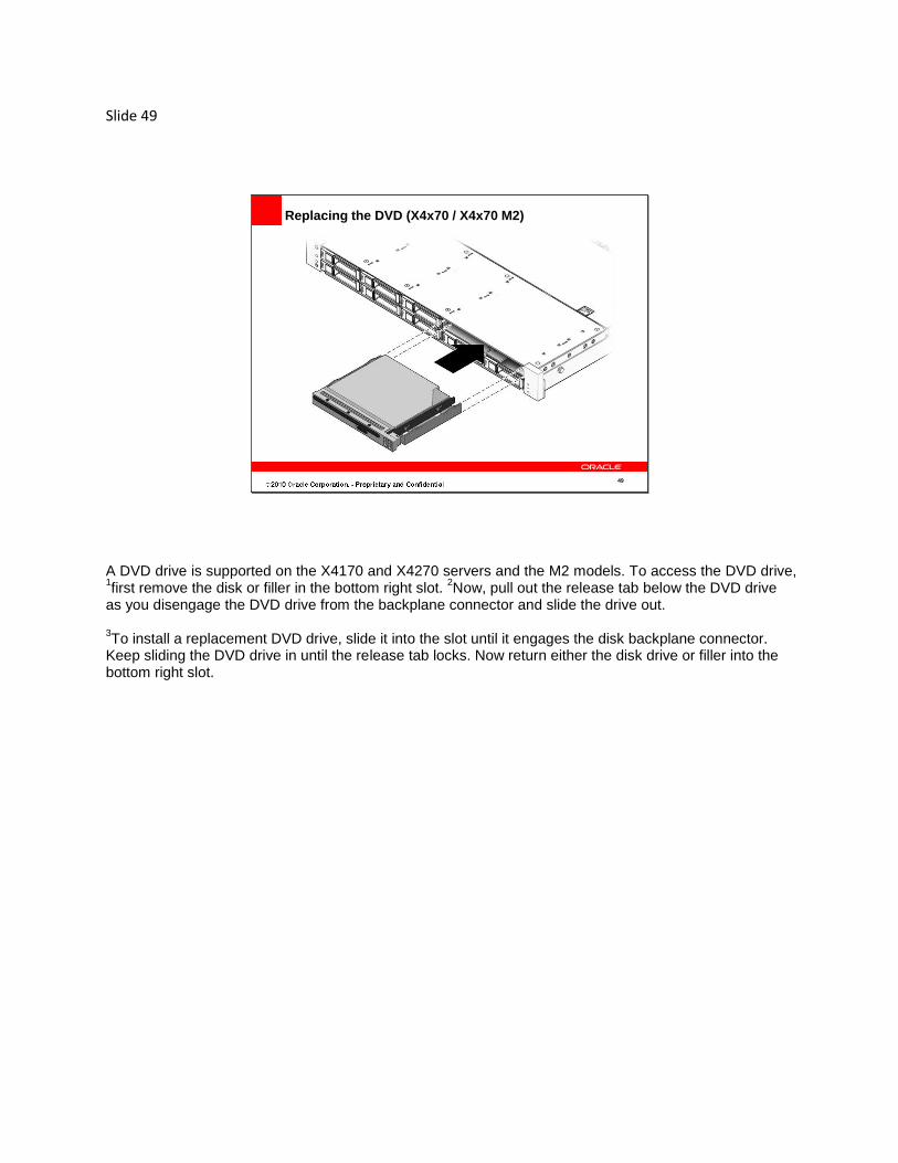
Replacing the DVD (X4x70 / X4x70 M2)
A DVD drive is supported on the X4170 and X4270 servers and the M2 models. To access the DVD drive, 1first remove the disk or filler in the bottom right slot.
2Now, pull out the release tab below the DVD drive
as you disengage the DVD drive from the backplane connector and slide the drive out. 3To install a replacement DVD drive, slide it into the slot until it engages the disk backplane connector.
Keep sliding the DVD drive in until the release tab locks. Now return either the disk drive or filler into the bottom right slot.

Slide 50
50
Replacing the Storage Drive Cage (X4170 / X4170 M2)
Remove:
• disk drives (record their slot positions)
• DVD
To access the storage drive cage, you first have to remove all the disk drives and the DVD from the cage recording the slot positions of each disk drive.
1Now you can start the removal of the storage drive cage
2by removing the four Phillips screws that holds the cage and backplane assembly in the chassis and
disconnecting all the disk backplane cables. 3Slide the cage assembly forward to disengage the it from
the paddle board then lift it out of the chassis. Refer to the disk backplane procedure to separate the backplane from the storage drive cage. To install a replacement storage drive cage,
4reverse the procedure by sliding in the cage assembly,
engaging it to the paddle board, 5reconnecting all the disk backplane cables
6and securing it using the
four Phillips screws. Now return all the disk drives and the DVD.

Slide 51
51
Replacing the PDB (X4170 / X4170 M2)
On the X4170 and X4170 M2 servers, to access the Power Distribution Board you need to first remove the power supplies and the motherboard. To remove the PDB,
1disconnect the top cover chassis intrusion
switch cable from the PDB 2then remove the Phillips screw that holds the PDB to the chassis.
3Now
disengage the PDB edge connector from the paddle board by pulling the assembly to the right using the bus bar and lift it out of the chassis. 4To install a replacement PDB, reverse the procedure placing the PDB in the chassis,
5sliding it to
engage its edge connector with the paddle board 6then reconnecting the intrusion cable and securing the
PDB with the Phillips screw.
Slide 52
52
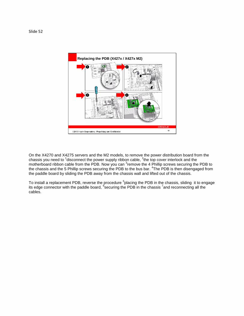
Replacing the PDB (X427x / X427x M2)
On the X4270 and X4275 servers and the M2 models, to remove the power distribution board from the chassis you need to
1disconnect the power supply ribbon cable,
2the top cover interlock and the
motherboard ribbon cable from the PDB. Now you can 3remove the 4 Phillip screws securing the PDB to
the chassis and the 5 Phillip screws securing the PDB to the bus bar. 4The PDB is then disengaged from
the paddle board by sliding the PDB away from the chassis wall and lifted out of the chassis. To install a replacement PDB, reverse the procedure
5placing the PDB in the chassis, sliding it to engage
its edge connector with the paddle board, 6securing the PDB in the chassis
7and reconnecting all the
cables.

Slide 53
53
Replacing the Motherboard (X2270 / X2270 M2)
Remove:
air duct
SP module
PCIe cards
PCIe riser assembly
FMODs,
DIMMs
CPU and heat sink assemblies
All cables attached to the motherboard
To access the motherboard on the X2270 and X2270 M2 servers, you need to remove the air duct, the SP module, any PCIe cards, the PCIe riser assembly, the FMODs, the DIMMs and the CPU and heat sink assemblies. In addition, you need to disconnect all cables attached to the motherboard and keep them clear of the motherboard. 1Now to remove the motherboard
2remove the eight screws that secure the motherboard to the chassis
then lift the motherboard straight up and out of the chassis. 3To install a replacement motherboard, place
it in the chassis with eight screw holes aligned then secure the motherboard in the chassis. Now replace all the components you removed to access the original motherboard.

Slide 54
54
Remove:
• SAS cables
• DIMMs
• CPUs
• FMODs
• PCIe riser and card
• ESM
Replacing the Motherboard (X4170 / X4170 M2)
To access the motherboard on the X4170 and X4170 M2 servers, you need to disconnect the SAS cables from the SAS PCIe card or the on-board SATA connectors on the motherboard. Then remove the DIMMs, the CPUs, the FMODs, PCIe risers, the PCIe cards, and the ESM. To remove the motherboard,
1disconnect the power distribution board ribbon cable,
2remove the four
screws that secure the motherboard to the bus bar, loosen the captive screw on the front of the motherboard that secures the motherboard to the chassis.
3Then using the finger loop just below the four
screws that secure the motherboard to the bus bar, carefully slide the motherboard to the rear of the chassis and lift it out of the chassis.
4Also, remove the screw that secures the finger loop/air plenum to the
motherboard and set the it aside. 5To install a replacement motherboard, reverse the procedure starting with the finger loop/air plenum.
6Slide in the motherboard into the chassis
7and secure it to the bus bar using the 4 screws
8then reinstall
the PDB ribbon cable.

Slide 55
55
Remove:
• Air Baffle
• SAS cables
• DIMMs
• CPUs
• FMODs
• PCIe riser and card
• ESM
Replacing the Motherboard (X427x / X427x M2)
To access the motherboard on the X4270 and X4275 servers and the M2 models, you need to remove the plastic air baffle, disconnect the SAS storage drive cables from the SAS PCIe card or the on-board SATA connectors located on the motherboard, the DIMMs, the CPUs, the FMODs, the PCIe risers and attached PCIe cards, and the ESM. To install a replacement motherboard,
1disconnect the power distribution board ribbon cable,
2remove the
four screws that secure the motherboard to the bus bar and loosen the captive screw on the front of the motherboard that secures the motherboard to the chassis. Now using the finger loop just below the four screws that secures the motherboard to the bus bar, carefully slide the motherboard to the rear of the chassis and lift it out of the chassis. 3To install a replacement motherboard, reverse the procedure by sliding the motherboard into the chassis
and secure it to the bus bar using the 4 screws 4then reinstall the PDB ribbon cable.

Slide 56
PROPERTIES
On passing, 'Finish' button: Goes to Next Slide
On failing, 'Finish' button: Goes to Next Slide
Allow user to leave quiz: At any time
User may view slides after quiz: At any time
User may attempt quiz: Unlimited times

Slide 57
57
Summary
• Prepare the server for installation
• Prepare the server for component replacement
• Name the key steps of replacing the server or its
components
Now that you completed this module, you should be able to 1prepare the server and its components for
replacement and name the key steps in the replacement of its components. This completes this module.

Slide 58
58
Oracle is the Information Company

Slide 59
59
Oracle