Embed Size (px)
Citation preview

November 2005
Cascade Earth Sciences
12720 E. Nora Ave., Suite A Spokane, WA 99216
(509) 921-0290 www.cascade-earth.com
REMOVAL ACTION WORK PLAN & DESIGN DRAWINGS Azurite Mine Removal Action Mt. Baker-Snoqualmie National Forest Whatcom County, Washington
April 2011

CJ:;s A valmont ~ COMPANY J::. Conserving Resources. Improving Life.
REMOVAL ACTION WORK PLAN & DESIGN DRAWINGS Azurite Mine Removal Action Mt. Baker-snoqualmie National Forest (Administered by the Okanogan and Wenatchee National Forests) Whatcom County, Washington
Prepared For:
Prepared By:
Author(s)/Reviewer(s):
Report Date:
Project Number:
Submitted By:
Mr. Rod Lentz U.S. Forest Service Okanogan and Wenatchee National Forests 1240 2nd Ave. South Okanogan, WA 98840
Cascade Earth Sciences 12720 E. Nora Avenue, Suite A Spokane,WA 99216 (509) 921-0290
Jay E. Williams, PE, Managing Engineer II Clay Ellestad, PE, Project Engineer Dustin G. Wasley, PE, Principal Engineer
April2011
2010230015
~Engineer'R~ ==-------
Disclaimer: The contents of this document are confidential to the intended recipient at the location to which it has been addressed. The contents may not be changed, edited, and/or deleted. The information contained in this document is only valid on the date indicated on the original project file report retained by CES. By accepting this document, you understand that neither CES nor its parent company, Val mont Industries, Inc. (Val mont) accepts any responsibility for liability resulting from unauthorized changes, edits,
and/or deletions to the information in this document.

Cascade Earth Sciences – Spokane, WA Azurite Mine – Removal Action Work Plan PN: 2010230015 / Doc: 2011 Final Azurite Mine RA Work Plan.docx April 2011 / Page iii
CONTENTS 1.0 INTRODUCTION ............................................................................................................................... 1
1.1 Site Description ................................................................................................................................... 1 1.2 Summary of Data Gap Investigation .................................................................................................. 2 1.3 Schedule and Key Personnel .............................................................................................................. 4 1.4 Logistics ............................................................................................................................................... 5
2.0 REMOVAL ACTION ACTIVITIES .................................................................................................. 5 2.1 Summary of RA Activities ................................................................................................................. 5 2.2 Mobilization ........................................................................................................................................ 6 2.3 Road Use, Maintenance, and Traffic Control .................................................................................... 7 2.4 Clearing and Grubbing ........................................................................................................................ 7 2.5 Surface Water Diversion / Erosion Control Measures ...................................................................... 7 2.6 Wasterock Excavation and Placement ............................................................................................... 8 2.7 Reinforced Stabilized Slope and Compacted Berm .......................................................................... 8 2.8 Repository Cover Construction .......................................................................................................... 8 2.9 Passive Water Treatment Systems for Adit Discharges and Seeps .................................................. 9 2.10 Building Material, Equipment, and Miscellaneous Debris Removal and Disposal ......................... 9 2.11 Revegetation ........................................................................................................................................ 9 2.12 Adit/Working Closures ..................................................................................................................... 10 2.13 Road Obliteration .............................................................................................................................. 10 2.14 Schedule............................................................................................................................................. 11 2.15 Cost Estimate ..................................................................................................................................... 11
3.0 CONFIRMATION SAMPLING ....................................................................................................... 11 3.1 Wasterock and Soil Screening and Analysis ................................................................................... 11 3.2 Sampling Protocol ............................................................................................................................. 11 3.3 Sampling Designation and Labeling ................................................................................................ 11 3.4 Decontamination Methods ................................................................................................................ 12
4.0 QUALITY ASSURANCE AND QUALITY CONTROL PLAN ..................................................... 12 4.1 Field QA/QC ..................................................................................................................................... 12 4.2 Laboratory QA/QC ........................................................................................................................... 12 4.3 Construction Quality Assurance Plan .............................................................................................. 12
5.0 HEALTH AND SAFETY PLAN ...................................................................................................... 12
6.0 OPERATIONS AND MAINTENANCE PLAN ............................................................................... 12
TABLES Table 1. Wasterock Humidity Cell Leachate Analytical Results Table 2. Wasterock and Soil Analytical Results Table 3. TCLP and SPLP Results for Wasterock Table 4. Sequential Batch Test Leachate Analytical Results

Cascade Earth Sciences – Spokane, WA Azurite Mine – Removal Action Work Plan PN: 2010230015 / Doc: 2011 Final Azurite Mine RA Work Plan.docx April 2011 / Page iv
CONTENTS (continued)
DRAWINGS Sheet G-1. Vicinity Map and Sheet Index Sheet C-7. Camp and Borrow Areas Sheet C-8. Grading Plan Sheet C-9. Drainage and Erosion Control Details Sheet C-10. Tailings Cross Sections Sheet C-11. Tailings Cross Sections Sheet C-12. Tailings Cross Sections Sheet C-13. Repository Slope Face Details Sheet C-14. Supplemental Details Sheet C-15. Supplemental Details Sheet C-16. Existing Wasterock Pile Cross Sections
APPENDICES
Appendix A. Health and Safety Plan Appendix B. Final Mill Creek Fish Presence and Fish Passage Barrier Assessment Memo Appendix C. Final Engineering Assessment - Slope Stability Memo (2007)/Supplemental Geotechnical
Analysis: Soil Cover Stability Analysis (2009)/Supplement Geotechnical Memo-Correspondence (2011)
Appendix D. Laboratory Analyses Appendix E. Technical Specifications and Construction Quality Assurance Plan Appendix F. HELP Model Results Appendix G. Project Construction Schedule Appendix H. Construction Cost Estimate Appendix I. Draft Operation and Maintenance Plan

Cascade Earth Sciences – Spokane, WA Azurite Mine – Removal Action Work Plan PN: 2010230015 / Doc: 2011 Final Azurite Mine RA Work Plan.docx April 2011 / Page 1
1.0 INTRODUCTION The United States Forest Service (Forest Service) retained Cascade Earth Sciences (CES) to perform a Removal Action (RA) at the Azurite Mine (Site). The Engineering Evaluation / Cost Analysis (EECA) prepared by ASARCO outlines the following RA objectives for the Site:
Tailings Pile: Reduce the potential for contaminant migration that would result in unacceptable risk to human health and the environment. Reduce the potential for unacceptable risks to human or ecological receptors due to the ingestion of soil/dust/tailings. Reduce the potential for the erosion of the tailings pile by runoff.
Wasterock Piles: Reduce the potential for contaminant migration that would result in unacceptable risk to human health and the environment. Reduce the potential for unacceptable risks to human or ecological receptors due to the ingestion of soil/dust/wasterock. Reduce or eliminate the potential for mass failure of the larger wasterock pile into Mill Creek due to a flood or seismic event. Reduce the potential for the erosion of the wasterock piles by runoff.
Mine Adit Water: Reduce the potential for human ingestion of mine adit water and contaminant migration through mine water discharges, including discharges into Mill Creek that would result in unacceptable risk to human health and the environment.
Surface Seep Water: Reduce the potential for human ingestion of surface seep water and mine contaminant migration that would result in unacceptable risk to human health and the environment.
As outlined in the EECA, the risk-based cleanup concentration is 104 milligrams per kilogram (mg/kg) total arsenic. Cleanup of wasterock, tailings, and soil to this concentration is expected to be protective of both human and ecological receptors. This document comprises the RA Work Plan; a stand-alone site-specific Health and Safety Plan (HASP) has also been prepared for planned field activities and is included in Appendix A. 1.1 Site Description
The Site is located in the Mt. Baker-Snoqualmie National Forest (administered by the Okanogan and Wenatchee National Forests) in Whatcom County, Washington, near the southern edge of the Pasayten Wilderness Area, and approximately 19 air miles northwest of Mazama, Washington. Driving time one way from Mazama to the Site is estimated to be a minimum of 2.5 hours, depending on road and trail conditions. To access the Site from Mazama, take County Road (CR) 9140 (Mazama/Lost River/Goat Creek Road) northwesterly. It will eventually turn into Forest Road (FR) 5400. Continue on FR 5400 to Harts Pass (approximately ten miles from Mazama to the pass). At Harts Pass, turn left onto FR 700. Follow FR 700 to Forest Trail (FT) 475 and go left. Take FT 475 past the Whistler Mine, over Cady Pass, and down to Mill Creek. At FT 755, go left and along Mill Creek to the Azurite Mine and Tailing area (total distance traveled from Mazama is about 24 miles). According to the U.S. Geological Survey (USGS) Quadrangle Map – Azurite Peak, WA. (1963), as published in the Washington Atlas (1995), the Site is located in the north half of Section 18, Township 37 north, Range 17 east of the Willamette Meridian. The Site is situated at elevations ranging from approximately 4,600 feet above mean sea level (amsl) at the tailings pile to 4,350 feet amsl at Mill Creek below the tailings pile. Gold was historically mined at the Site, but the mine has been inactive for at least 60 years (pre-World War II). The Site is situated adjacent to Mill Creek, which discharges into Canyon Creek, then Ruby Creek, and eventually Ross Lake. Features of the Site include four adits: the Wenatchee, Tinson (flowing), Burnham, and Discovery. There is also a concrete foundation from a dismantled 100-ton per day flotation mill, along with a related tailings pile

Cascade Earth Sciences – Spokane, WA Azurite Mine – Removal Action Work Plan PN: 2010230015 / Doc: 2011 Final Azurite Mine RA Work Plan.docx April 2011 / Page 2
covering approximately five acres. The tailings pile is estimated at 55,000 bank cubic yards (bcy). In addition, two wasterock piles are located adjacent to the Wenatchee Adit, with a total estimated volume of 25,000 bcy (22,000 bcy of wasterock and 3,000 bcy of cover material). 1.2 Summary of Data Gap Investigation
CES conducted a Data Gap Investigation (DGI) on October 1 – 4, 2007. In addition, CES conducted a follow-up DGI on September 21-23, 2010 to gather additional field data and information to finalize the designs and details. Each of the data gaps are discussed in the following sections, with a brief description of the results. 1.2.1 Data Gap 1 – Mill Creek Fish and Fish Barrier Survey
CES submitted a technical memorandum on October 30, 2007, that summarized the results of the survey (Appendix B). In summary, multiple fish passage barriers (both temporary and permanent) were observed between the Site and the confluence with Canyon Creek. Dip nets were used opportunistically in pool and riffle habitats along the entire length of Mill Creek; no fish were caught. Only three very small unidentified, fish were observed, all downstream of Fish Barrier 05 which is approximately 2.4 miles downstream from the Site. Because of these conditions, and the presence of other bedrock fish passage barriers, it is deemed unlikely that fish have ever migrated upstream of Fish Barrier 04 (two miles downstream from Site) and most recently have not been able to migrate upstream of Fish Barrier 05. In addition, no records were found during the earlier Site Inspection (CES, 2004) indicating that fish had been transplanted into the upper reaches of Mill Creek. Thus, fish are unlikely to have ever inhabited Mill Creek within two miles of the Site.
1.2.2 Data Gap 2 – ViroMine Adit/Seep Sampling and Bench Testing
Due to weather and safety conditions, CES was only able to collect one water sample. CES selected the tailings seep as the best seep to sample because the Wenatchee wasterock seep water quality and quantity will likely significantly change once the wasterock has been removed and the native ground is exposed; and the low flow and metal concentrations of the Tinson Adit are most likely not impacting Mill Creek. Ten gallons of water from the tailings seep was collected and shipped to Virotec USA on October 10, 2007, for jar and bench testing using the ViroMine™ technology. CES was in communication several times with Virotec personnel following submittal of the sample regarding field parameters, flow rates, etc. Based on our signed agreement with Virotec, CES was expecting to receive the draft results of the testing in late November 2007. In late November and early December 2007, CES attempted repeatedly to contact Virotec personnel via email and phone regarding the status of the testing. On December 6, 2007, CES received an email from Lee Fergusson (CEO of Virotec International – parent company of Virotec USA) stating that there had been some organizational changes and that our contact (Jim Jonas) was no longer with Virotec and that he would check into the status of the sample and testing. After several weeks of communication with Mr. Fergusson, CES discovered that the bench testing had not been performed and the sample was being stored at the Virotec facility in Denver, Colorado. CES requested that the sample be shipped back to CES; however, it was discovered that the sample was not properly stored. Based on this, the sample was discarded. CES will work with the Forest Service to further assess appropriate water treatment technologies prior to implementation of the RA. 1.2.3 Data Gap 3 – Borrow Material Assessment
During the 2007 DGI, CES planned on using a helicopter and all terrain vehicles (ATV) to assess borrow material areas in the Barron and Harts Pass areas. However, these areas could not be assessed due to snow levels and lack of visibility in the helicopter. CES did assess potential sources of on-site cover soil. There appears to be 3,000 to 5,000 bcy of uncontaminated cover soil / overburden at the Wenatchee wasterock area. In addition, there appears to be additional cover soil resources approximately 0.35 to 0.5 miles south of the Site along the trail on the eastern side of Mill Creek. CES was not able to mobilize equipment to this area to collect samples but, based on visual observations, there appears to be a significant amount of suitable cover

Cascade Earth Sciences – Spokane, WA Azurite Mine – Removal Action Work Plan PN: 2010230015 / Doc: 2011 Final Azurite Mine RA Work Plan.docx April 2011 / Page 3
soil on a bench above Mill Creek. In addition, there appears to be sufficient quantities of talus and riprap that can be scavenged from the general vicinity around the Site. During the September 2011 DGI, CES performed additional reconnaissance of the talus borrow area, located in the drainage to the south of the Site. Based on CES assessment and field mapping, there appears to be ample talus material to construct the repository cover. Sheet C-8 shows the general dimensions of the talus source area. If additional source material is needed, CES will work with the Forest Service to identify additional suitable sources around the Site. Screening will need to be performed in order to remove the large and small talus material. In general, the talus will be screened from 8-inches to ½-inch, which will serve as the cover for the repository. Screened material that is larger than 8-inches will be used as riprap around the Site and potentially in the toe berm on the repository. Screened material ½-inch and less will be used as road bedding, and potentially fill material for the reinforced mechanically stabilized toe berm. 1.2.4 Data Gap 4 – Road Improvements Assessment
CES performed a general assessment of the access road to determine areas where improvement is required for equipment access to the Site. Specifically, CES assessed the bridges, culverts, and switchbacks. Suggested improvements are outlined in Section 2 of the Work Plan and shown on the Drawings. 1.2.5 Data Gap 5 – Geotechnical Assessment
CES subcontracted with GeoEngineers in Spokane, Washington to perform the Geotechnical Assessment and slope stability modeling of the Site and recommended RA alternative. As part of the assessment, test pits were excavated to investigate the subsurface soil conditions on the downgradient side of the tailings pile and repository location. In addition, test pits were excavated in the wasterock piles, samples were collected and a soil cover stability analysis was completed. Results of the investigation and analysis are outlined in the technical memorandum (Appendix C), and were incorporated into the overall Removal Design and layout. In order to provide a surface that is more practical for construction of a cover, we are proposing to place wasterock on top of the tailings pile and raise the toe berm (height will vary between 5 and 15-ft) to provide a uniform slope on which to construct the cover. The proposed configuration would be a surface slope of 2.5H:1V with 8-foot wide anchor benches located a minimum of every 20 feet of slope distance. The benches would direct precipitation away from the slope face to the north or south drainage channels. The impervious cover is detailed on Sheet C-14 and technical specifications, and will consist of the following:
1. 6 to 12 inch talus cover (generally screened from 8-inchs to ½-inch) 2. Uniaxial geogrid 3. 12 oz. non woven geotextile 4. 40-mil HDPE geomembrane 5. 12 oz. non woven geotextile 6. Wasterock 7. Tailings
This system will protect the HDPE geomembrane from damage due to rocks either above or below the geomembrane, and the geogrid will provide the strength to protect against pullout or tearing. 1.2.6 Data Gap 6 – Humidity Cell and Sequential Batch Soil Attenuation Results
Although prior work at the Site indicated that the wasterock is acid producing, CES elected to obtain rates of acid production and neutralization/attenuation potential of soil underlying the proposed repository to determine if underlying soil will attenuate metals in the leachate and potentially limit the need for an impermeable cover. CES obtained samples of wasterock, tailings, and underlying soil for metals analyses, static acid based accounting (ABA), dynamic ABA, and soil attenuation testing. CES contracted with ACZ Laboratories (ACZ) for chemical analyses and static ABA testing. CES also contracted with McClelland
Cascade Earth Sciences – Spokane, WA Azurite Mine – Removal Action Work Plan PN: 2010230015 / Doc: 2011 Final Azurite Mine RA Work Plan.docx April 2011 / Page 4
Laboratories, Inc. (MLI) for dynamic ABA (humidity cell [HC]) testing and soil attenuation (sequential batch [SB]) testing. As the first step, MLI conducted HC tests in accordance with ASTM protocol for five weeks. A portion of the leachate from each weekly event was sent to ACZ for analysis; the remainder of the leachate was frozen for SB testing. The assumption was that the HC leachate would simulate discharge from the wasterock for use in SB tests using underlying soil to determine metals attenuation. MLI’s report is provided in Appendix D – Laboratory Results. Results of all analyses and tests are provided in Tables 1 through 4. The results and conclusions of all tests are summarized as follows:
Table 1 indicates that the upper wasterock is clearly pyritic and strongly acid producing. The lower wasterock; however, is non-acidic and actually produces alkalinity.
Table 2 indicates that the upper wasterock is rich in metal sulfide minerals with an acid-base potential of -99 tCaCO3/Kt (ABP units are presented as tons of calcium carbonate needed to neutralize a kiloton of waste). The lower wasterock and a portion of the upper wasterock; however, exhibited an acid base potential of 12 to 20 tCaCO3/Kt (acid neutralizing). The soil at the proposed repository location exhibited an average acid base potential of average of 3.7 tCaCO3/Kt.
Table 3 shows that neither the upper nor the lower wasterock will exceed the toxicity characteristic leaching procedure (TCLP) limits and be considered as Dangerous Waste as defined by the Washington State Department of Ecology (Ecology). The data further indicates that the synthetic precipitation leaching procedure (SPLP) leachate did not exceed the Ecology Model Toxics Control Act (MTCA) for protection of groundwater.
Table 4 illustrates the results of the SB tests. These were performed by collecting adequate HC leachate to simulate a 24-hour 100-year storm event of 6.5 inches of precipitation. The HC effluent (SEQ-INF) was passed through the first column of repository underlying soil (S-1). The S-1 discharge was passed through a second soil column (S-2), and this effluent was in turn passed through a third column (S-3). Based on the results, the underlying soil provides a high ability to attenuate acid and metals. Attenuation efficiencies ranged from 66.4% for sulfate to 99.9% for iron. However, a small amount of lead was actually added by the repository underlying soil. Again, it appears unlikely that any MTCA criteria for protection of groundwater will be exceeded. The soil will clearly attenuate small leaks and discharges, but it has not been determined if the soil will attenuate all available acid and metal from the wasterock and preclude the need for an impermeable cover.
1.2.7 Data Gap 7 – 2010 Spring and Fall Aquatic Sampling and Monitoring
In June and September 2010, CES collected additional surface water and sediment samples from the eight established aquatic stations in Mill Creek and Canyon Creek, plus two additional background stations in Mill Creek. In addition, surface water samples were collected from the three seep (Tinson Adit, Wenatchee wasterock seep, and tailings seep). Results of the 2010 sampling and monitoring events are provided in Appendix D.
1.3 Schedule and Key Personnel
Implementation of the RA is expected to be accomplished in one field season. The field season at the Site is typically between late June and early October, depending on snow levels. The timeframe of the RA construction activities has not been planned or established and will be based on Forest Service budgets and priority of projects.

Cascade Earth Sciences – Spokane, WA Azurite Mine – Removal Action Work Plan PN: 2010230015 / Doc: 2011 Final Azurite Mine RA Work Plan.docx April 2011 / Page 5
The field team scheduled to perform work during field operations include:
Dustin Wasley, PE – CES Project Manager / Principal-in-Charge
Jay Williams, PE – CES Senior Engineer / Engineer of Record
Tim Otis, PE – CES Senior Engineer / Field Inspector
Ryan Tobias – CES Project Biologist / Field Inspector
Kaylan Smyth – CES Staff Engineer / Field Inspector
All personnel who will be performing invasive activities (i.e., sampling, construction oversight, etc.) during the RA are trained to work in hazardous environments as defined by the Occupational Safety and Health Act (OSHA) 1910.120. In addition, Mr. Tobias and Ms. Washington are certified under the Mine Safety & Health Administration (MSHA) training requirements outlined in Public Laws 91-173 and 95-164. Other personnel who will periodically be on site are listed below. The Contracting Officer Representative (COR) will be kept informed regarding project activities, plans, schedules, budget/invoicing, and other issues through monthly phone meetings.
Rod Lentz – Forest Service On-Scene Coordinator (OSC)/COR
Others Authorized Forest Service Personnel 1.4 Logistics
Due to the remoteness of the Site, the existing office building will be minimally improved to serve as the office for the RA implementation. In addition, a temporary camp will be established for the implementation of the RA (see Sheet C-8). The camp will include tents, a cooking and eating area, as well as shower and sanitary facilities (porta potties). Care will be taken to avoid any significant impacts to forest resources and to reduce the potential for non-work related exposure to potentially hazardous materials known to be present at the Site. All food, equipment, and other supplies will be packed in and out, and will be stored in bear-proof containers and in a manner not to attract wildlife. All refuse will be stored in bear-proof containers, and routinely packed out of the Site and properly disposed at an approved solid waste facility. The camp area will be cleaned-up and left in good condition prior to departure, and if needed graded and revegetated in accordance with the other reclamation at the Site. ATVs will likely be used as part of the Removal Action, which will require that a small supply of fuel be kept available at the Site. To control problems, the following fuel handling procedures will be employed:
Only containers approved for gasoline will be used.
A storage area with secondary containment will be established at the Site.
Care will be taken to avoid spills during refueling.
Refueling will be done near the fuel storage area, to the greatest practical degree.
There will be no open flames or other sources of ignition allowed in the vicinity of the fuel storage area or during refueling operations.
2.0 REMOVAL ACTION ACTIVITIES 2.1 Summary of RA Activities
The work will consist of, but not be limited to, providing all labor, materials, earthwork, and incidentals necessary to excavate and transport wasterock piles from the west side of Mill Creek to the repository, located over the tailings pile. The face of the repository will be wrapped with a Uniaxial Geogrid to maintain long-term structural stability. The upper wasterock pile will be placed as the bottom lift over the tailings, while the lower wasterock pile will be placed on top of the upper wasterock pile material in the repository. In addition, lower wasterock material will be placed in the mill area to fill in the benches and provide a uniform slope. In addition, minor amounts of eroded tailings that have deposited on or near the access road will be

Cascade Earth Sciences – Spokane, WA Azurite Mine – Removal Action Work Plan PN: 2010230015 / Doc: 2011 Final Azurite Mine RA Work Plan.docx April 2011 / Page 6
scrapped and placed within the repository. The tailings pile will also be minimally graded to promote positive drainage along the various benches. An impervious cover will be placed over the repository and mill area, and will consist of the following:
1. 6 to 12 inch talus cover (generally screened from 8-inches to ½-inch) 2. Uniaxial geogrid 3. 12 oz. non woven geotextile 4. 40-mil HDPE geomembrane 5. 12 oz. non woven geotextile 6. Wasterock/Tailings/Soil
Other work will consist of maintaining the access road by keeping culverts cleaned and flowing, and repairing minor erosion issues. In addition, bat gates will be installed at the five adits/workings. Water discharging from tailings seep, wasterock seep, and Tinson Adit will be treated/managed using a method to be determined in the future. Related mobilization, clearing and grubbing, road improvement and maintenance, erosion control, roadway obliteration, and revegetation will also be performed. Signs will also be posted to warn the public of the general hazards (both chemical and physical) associated with the tailings, wasterock, and metal-impacted seeps/drainages. Logistical difficulties associated with the performance of this project include the remoteness of the Site and generally steep slopes located throughout the area, which will require special handling. The remote location may cause mobilization difficulties and may complicate delivery of the required materials. The following sections are the main components of the RA and are listed in order of sequence. Construction drawings/sheets are attached, the exact layout and RA activities will be determined in the field through consultation between CES and the OSC/COR. All “field engineering” procedures, plans, and designs will be discussed with and approved by the OSC/COR prior to implementation. Technical Specifications (in CSI format) and the Construction Quality Assurance (CQA) Plan are attached in Appendix E. 2.2 Mobilization
Mobilization will be performed in accordance with Section 00190 of the Technical Specifications. The initial mobilization date will be determined in the future. The following general equipment will be used during the RA activities; CES assumes that the bridge weight limits are sufficient to allow transportation of equipment to the Site (the highest weight equipment is 80,000 lbs or 40 tons):
3 Pickup trucks
3, 35-ton rock trucks
2 wheeled loaders
2 Caterpillar D6 bulldozers or equivalent
2 Caterpillar 330 Excavators or equivalent
1 small backhoe/excavator for road maintenance
Equipment will be thoroughly pressure washed and cleaned to remove dirt/weeds prior to arrival on-site; the equipment will be made available for inspection prior to mobilization to the Site. Historic and archeologically significant areas will be marked with orange flagging after consultation with the Forest Service. Equipment staging areas are planned to be on the south side of the Site (Sheet C-8). Equipment will also be staged on roadways as not to block access to and from the Site. In addition, a temporary camp is proposed to be on the south side of the Site (see Sheet C-8). The Office Building may also be partially improved to serve as a temporary office/storage building.

Cascade Earth Sciences – Spokane, WA Azurite Mine – Removal Action Work Plan PN: 2010230015 / Doc: 2011 Final Azurite Mine RA Work Plan.docx April 2011 / Page 7
2.3 Road Use, Maintenance, and Traffic Control
The main access road/trail will close for public use for the construction season during the RA implementation. Signs will be posted at the beginning of the road/trail (near the Slate Creek bridge) advising the public that the road is not open for public use and warning of construction equipment usage. The gate will be closed and locked at all times. Flaggers will not be needed because of the limited traffic on this road/trail. The existing access road was improved by the Forest Service during the summer/fall of 2010, additional improvements are scheduled to be performed by the Forest Service during the spring of 2011, before mobilization for the RA. During the course of the RA, the access road will be maintained, culverts kept clean, and erosion repairs will be made in a timely manner. The unimproved access road from the tailings pile to the wasterock pile (estimated at 0.2 miles) will be improved to allow 35-ton rock trucks to transport wasterock to the repository. Improvements will consist of grading and placement of road material, and installation of erosion control devices (see Section 2.5). A temporary crossing will be constructed in Mill Creek (Sheet C-14) to allow vehicular access and minimize disturbance to the aquatic environment. CES will erect warning signs, in advance, on any place on the project where operations may interfere with the use of the road or trail by traffic and at all intermediate points where the new work crosses or coincides with an existing road or trail. CES will notify the District Ranger two weeks prior to mobilization of substantial equipment that will limit the public use of the Harts Pass Road. In addition, the Contractor will provide pilot cars or flaggers at Dead Horse Point to stop other vehicles at designated turnouts. 2.4 Clearing and Grubbing
Clearing and grubbing, performed at the direction of CES and in accordance with Section 02130 of the Technical Specifications, will be kept to a minimum, and will only disturb areas within the limits of the Site and other minor areas for access. Grubbed material and slash will be stockpiled on-site for shredding as mulch to use during the revegetation. 2.5 Surface Water Diversion / Erosion Control Measures
Prior to invasive activities, sediment control devices (i.e., straw bale barrier or silt fencing) must be installed adjacent to Mill Creek and tributaries to control the migration of sediment into surface water bodies. The location of the sediment control devices will be determined by CES after consultation with the OSC/COR. The sediment control devices will be installed in accordance with manufacturer details and specifications and at the direction of CES. In addition, flocculants will be available at the Site in case of discharge from the sedimentation basins; CES will work with the Contractor and manufacturer to identify the most appropriate flocculants. Typical details are shown in the Design Drawings on Sheet C-9. Specifications are located in Appendix E, Section 02251. Mill Creek will be temporarily diverted away from the wasterock piles towards the eastern bank to minimize the amount of spillage that falls into the creek during removal. Wasterock that deposits in the floodplain will be removed in an expeditious manner, to the extent practical based on high river flows and wasterock stability. In addition, at the direction of CES and as shown on the Drawings, stormwater and snowmelt run-on would be controlled on the upgradient side by constructing run-on control ditches or berms that channel the water around the revegetated areas. Typical details are shown on Sheet C-14; run-on ditches were sized for the 100-year, 24-hour storm event.

Cascade Earth Sciences – Spokane, WA Azurite Mine – Removal Action Work Plan PN: 2010230015 / Doc: 2011 Final Azurite Mine RA Work Plan.docx April 2011 / Page 8
2.6 Wasterock Excavation and Placement
The upper and lower wasterock piles will be excavated to the limits shown on the Drawings and in accordance with Section 02220 – Excavation and Embankment of the Technical Specifications. The approximate lines and grades are shown on the Drawings, the extent and depth of the removal will be based on field observations and results of x-ray fluorescent (XRF) in-situ field screening (the risk-based cleanup concentration is 104 mg/kg total arsenic). The estimated volume of wasterock to be removed is 22,000 bcy. In order to control the release of wasterock and sediments into Mill Creek, excavation and transport of the wasterock will proceed in a careful manner working from the top of the slope down. In addition, Mill Creek will be diverted away from the wasterock pile to the eastern bank during the excavation activities. Details have been included on Sheet C-8. The excavated wasterock will be transported and placed over the tailings and mill area as shown on the Drawings and in accordance with Section 02220 of the Technical Specifications. Based on the HC and SB testing and laboratory analysis, the upper wasterock pile (which has the highest acid generating material) will first be placed over the tailings and the lower wasterock pile (which has the highest acid buffering capacity) will be placed over the upper wasterock. Wasterock will be placed in six-inch to 12-inch lifts and equipment compacted to 90% of standard proctor (Specification 02220.3.12 – Method 2). During the excavation of the wasterock and construction of the repository, the Contractor shall not discharge dust or any other air contaminants into the atmosphere in such quantity as will violate the regulations of any legally constituted authority. At the first sign of fugitive emissions, water will be applied using an atomized spray until visually damp. Special consideration will be given not to over water the wasterock. No ponding or runoff from the wasterock will be allowed. CES assumes that water can be pumped directly from Mill Creek. The Contractor will provide access to the excavation areas, and shall sequence excavation and other activities to accommodate sampling and analysis work by the Engineer and OSC/COR. Haul trucks will not be overfilled in order to minimize spillage of wasterock. If spillage occurs, the Engineer may require the trucks to be covered during transport. Loading areas and spur roads shall remain free of spilled material, to the extent practical, to avoid tracking of wasterock and contaminated soil along the haul routes. Wood and metal debris that is encountered in the excavation area shall be separated and either burned on-site or transported offsite for disposal following approval by the OSC/COR. 2.7 Reinforced Stabilized Slope and Compacted Berm
In order to provide structural integrity to the repository, an engineered reinforced stabilized slope and a compacted berm will be constructed at the toe of the repository. The reinforced stabilized slope will be constructed using fill material at the Site (talus screens, talus, and uncontaminated overburden beneath the wasterock pile), and will be the first 385 feet along the toe, and 15-feet in height as shown on Sheet C-8, in details on Sheet C-13, and in Specifications 00270. In addition, a compacted berm (5-feet high and 8-feet wide) will be constructed along the remaining toe of the repository, as shown on C-8 and in details on Sheet C-13. The compacted berm will be constructed with uncontaminated overburden beneath the wasterock pile, or another suitable source identified by CES or the COR. 2.8 Repository Cover Construction
To meet the RA objectives as outlined in Section 1 and the EECA, an impervious cover will be constructed over the consolidated tailings and wasterock to control the migration of contaminates and erosion potential, including both the tailings and mill area repositories. The cover will consist of the following:

Cascade Earth Sciences – Spokane, WA Azurite Mine – Removal Action Work Plan PN: 2010230015 / Doc: 2011 Final Azurite Mine RA Work Plan.docx April 2011 / Page 9
Benches will be constructed every 20 feet at the tailings repository and sloped 2% to the north to manage and divert water away from the slope face. Benches will not be needed at the mill site repository because of the low final slope angle.
A 12-oz geotextile will be placed directly over the tailings/wasterock overlain with a 40-mil HDPE liner, followed by a 12-oz ounce non-woven geotextile, and finally a uniaxial geogrid (approximately 160,000 square feet each layer of HDPE liner, geogrid, and geotextile).
Available talus will be placed on each of the benches as shown on the Drawings.
Talus material will be generated from the borrow area shown on Sheet C-8. Screening will need to be performed in order to remove the large and small talus material. In general, the talus will be screened from 8-inches to ½-inch, which will serve as the cover for the repository and mill area. Screened material that is larger than 8-inches will be used as riprap around the Site and potentially in the toe berm on the repository. Screened material ½-inch and less will be used as road bedding, and fill material for the reinforced mechanically stabilized toe berm.
The 8,000 bcy of talus material needed for the cover is available in the vicinity of the Site as shown on drawing C-10.
Tailings slope will be 2.5 H:1V or greater between benches, unless otherwise approved by the Engineer.
2.9 Passive Water Treatment Systems for Adit Discharges and Seeps
Passive water treatment systems, if needed, will be assessed, selected, designed, and installed after field monitoring confirms stabilization of flow rates and water quality parameters. 2.10 Building Material, Equipment, and Miscellaneous Debris Removal and Disposal
All building material, process equipment, and nuisance debris (estimated at ten tons) at the Site that pose a potential physical and chemical hazard to Site users will be removed following review and approval by the OSC/COR. Material will be transported and disposed at a local landfill. The former Office Building and all concrete foundations will be left intact, unless the foundations need to be removed due to contamination. This will be discussed with the OSC/COR before any foundations are removed. Special care will be taken not to disturb areas that will be identified by the Forest Service as archeologically or historic significant areas. These areas will be marked with orange flagging at the start of the project by the Forest Service. 2.11 Revegetation
All disturbed areas (estimated at two acres) will be recontoured and revegetated in accordance with Section 02801 - Seeding of the Technical Specifications. Growth media may be added where substrate is inadequate as directed by the Engineer, this is dependent on available growth media onsite. Prior to placement, growth media will be checked with an XRF to document that metal concentrations are below the cleanup goal. The Forest Service will provide grass and forb seeds, and no fertilizer will be applied during the revegetation activities. In addition, at the direction of the Engineer and the Forest Service, a trench (2-feet deep, by 2-feet wide, by ~400-feet long) will be excavated in the area of the former wasterock pile, along the Mill Creek. The trench will be used to plant live willow cuttings (provided by the Forest Service). Following planting, the trench will be backfilled with trench spoils. The Forest Service will also supply approximately 1,670 seedling tublings for planting around the former wasterock pile area. Extra and left over tublings may be planted in other areas as directed by the COR.

Cascade Earth Sciences – Spokane, WA Azurite Mine – Removal Action Work Plan PN: 2010230015 / Doc: 2011 Final Azurite Mine RA Work Plan.docx April 2011 / Page 10
2.12 Adit/Working Closures
To minimize human access, while allowing small mammal access (e.g., bats), closures will be installed at each of the five adits/openings, including the Tinson Adit, Wenatchee Adit, Burnham Adit, Discovery Adit, and the Discovery Winze. Bat gates and bat culvert typical details are shown on Sheet C-15, stiffeners are not required for the closures, with the exception of the Wenatchee Adit. The final layout of the gates and locking mechanism will be determined following consultation with the Forest Service, the Contractor, and assessment in the field. Access to several of the adits/workings (Discovery Adit, Discovery Winze, and Burnham Adit) will require the use of a helicopter. To the extent practical, closures will be fabricated at the Site and flown into place with the helicopter. Access to the Tinson Adit and Wenatchee Adit will be accomplished with the use of ATVs or standard equipment/trucks. In general, the following sections provide a summary of the dimensions and logistics of the workings. 2.12.1 Tinson Adit
Dimensions: (~6-ft wide x 6.5-ft high) Access: ATVs Water: Flowing Preferred closure: Bat Gate
2.12.2 Discovery Adit
Dimensions: (~6-ft x 6-ft) Access: Hiking and helicopter Water: None Preferred closure: Bat Gate
2.12.3 Discovery Winze
Dimensions: (3-ft x 3-ft) Access: Hiking and helicopter Water: None Preferred closure: Grate
2.12.4 Burnham Adit
Dimensions: (Triangle, see to right) Access: Hiking and helicopter Water: None Preferred closure: Culvert with gate
2.12.5 Wenatchee Adit
Dimensions: Unknown, likely 6-ft x 6-ft Access: Truck/ATV Water: Unknown Preferred closure: Bat Gate, with stiffeners
2.13 Road Obliteration
Upon completion of RA construction activities, roads within the limits of the Site and other access roads constructed during the RA will be decommissioned. Decommissioning will consist of recontouring the road for proper drainage, ripping to 12 inches, seeding, fertilizing, and mulching as specified in Section 02110 – Obliteration of Abandoned Roadways of the Technical Specifications. The main access road will be left open to allow access for operation and maintenance activities.
Adit 7.5-ft
10-ft
8-ft 7.8-ft

Cascade Earth Sciences – Spokane, WA Azurite Mine – Removal Action Work Plan PN: 2010230015 / Doc: 2011 Final Azurite Mine RA Work Plan.docx April 2011 / Page 11
2.14 Schedule
The implementation of the RA is anticipated to be completed in one season, assuming a three-month construction window. The proposed schedule is attached as Appendix G, and assumes an initial mobilization of June 28, 2010. This schedule is considered preliminary and will most likely change depending on field conditions. In addition, following the completion of the RA, CES or the Forest Service will provide an annual assessment of the repository and mill area covers, water treatment system (to be determined), and other improvements. Surface water and sediment samples should also be collected from the established aquatic stations to help evaluate the overall success of the RA. Details of the annual inspection and sampling will be determined following consultation with the Forest Service. 2.15 Cost Estimate
A Construction Cost Estimate was determined by CES and is attached as Appendix H. 3.0 CONFIRMATION SAMPLING This section presents the sampling plan that will be employed at the Site to document that impacted wasterock and tailings above the risk-based cleanup concentration of 104 mg/kg total arsenic is contained within the wasterock repository and tailings cover. 3.1 Wasterock and Soil Screening and Analysis
During the RA activities, CES will use an XRF (model to be determined) to field test the limits of excavation. CES will follow the EPA recommended protocols (i.e., drying, sieving, splitting, etc.) for using the XRF. As a general rule, concentrations measured with an XRF are typically higher than laboratory results. Therefore, confirmation samples will also be collected when XRF results are below the cleanup concentration of 104 mg/kg total arsenic. The number and locations of the confirmation samples will be determined in the field. Due to the nature of the RA activities sequence, delays in receiving analytical results, and the screening level nature of the XRF, there is a possibility that confirmation sample results could be slightly higher than the cleanup goal of 104 mg/kg. The confirmation sample results will be reviewed with the Forest Service to determine if additional excavation is needed. If soil is left in place higher than the cleanup goal, a residuals risk assessment will be prepared to review the average concentrations, and to provide documentation that there are no unacceptable risks. 3.2 Sampling Protocol
All confirmation samples shall be collected as discrete samples from specific locations. Confirmation samples shall be collected from fresh, undisturbed material from the walls and bottom of the excavation using a stainless steel spoon. Sample material will be placed in laboratory-supplied four ounce glass jars with Teflon-lined lids, and stored in a cooler on ice. 3.3 Sampling Designation and Labeling
The following sample numbering system will be used to identify conformation samples: Waste and Soil Sample Number Example: AMRA-UWR1-5’ Where:
AMRA = Azurite Mine Removal Action UWR = Upper Wasterock (LWR = Lower Wasterock) SS = Site Soils NS = Native Soils
1 = Sample Number 5’ = Depth of sample from below ground surface

Cascade Earth Sciences – Spokane, WA Azurite Mine – Removal Action Work Plan PN: 2010230015 / Doc: 2011 Final Azurite Mine RA Work Plan.docx April 2011 / Page 12
3.4 Decontamination Methods
All sampling equipment (bowls, trowels, augers, etc.) will be stainless steel, and will be decontaminated before sampling. Equipment decontamination consists of a tap water rinse, a soap and tap water wash, a dilute nitrate acid (HNO3) rinse (ten parts DI water to one part concentrated HNO3), and a DI water rinse followed by air drying. Decontamination water will be discharged directly to soils at the Site. 4.0 QUALITY ASSURANCE AND QUALITY CONTROL PLAN The following standards will be maintained during sampling and analysis to see that the data generated for the assessment meets data quality objectives outlined in Data Quality Objectives for Remedial Response Activities, Development Process. All laboratory and field data will be subject to EPA Level II quality assurance/quality control (QA/QC) standards. All values between the method detection limit (MDL) and the practical quantitation limit (PQL) will be noted on the laboratory analytical reports. 4.1 Field QA/QC
According to the EPA QA/QC Guidelines, one duplicate and one equipment rinsate blank should be analyzed for every ten samples collected. The intent of these guidelines is to assess the precision of field sampling, and verify that contamination has not occurred in the field and that decontamination procedures were followed. Equipment rinsate blank samples will be collected during sampling activities to test for cross-contamination between samples by pouring distilled water over decontaminated sampling equipment into the sampling container. The rinsate and duplicate samples will be given unique labels; the samples will be analyzed for total arsenic. All samples will be collected in laboratory-supplied jars and bottles, labeled, and transported according to the protocol described above. A chain-of-custody will be maintained from the time of sample collection until the time the samples are received by the analytical laboratory. The chain-of-custody will be signed by anyone who accepts responsibility for the samples, except the shipper. Shipping documents will represent custody of the samples by the shipper. 4.2 Laboratory QA/QC
The laboratory will follow all requirements for analysis and reporting under the EPA Level II protocols, including, laboratory blanks, laboratory duplicates, matrix spikes, and matrix spike duplicates. All samples will be analyzed within the holding times specified for the individual analytical procedure. Any sample analysis completed after the specified holding time will be noted in the laboratory analytical report. All analytical reports will be reviewed to see that all spikes, duplicates, and lab blanks are within acceptable limits. 4.3 Construction Quality Assurance Plan
The Construction Quality Assurance Plan is included in Appendix E. 5.0 HEALTH AND SAFETY PLAN The Site-Specific HASP has been prepared as a separate document, and is included as Appendix A. 6.0 OPERATIONS AND MAINTENANCE PLAN A Draft Operation and Maintenance Plan is included as Appendix I.

TABLES Table 1. Wasterock Humidity Cell Leachate Analytical Results Table 2. Wasterock and Soil Analytical Results Table 3. TCLP and SPLP Results for Wasterock Table 4. Sequential Batch Test Leachate Analytical Results

Table 1. Wasterock Humidity Cell Leachate Analytical ResultsAzurite Mine Removal Action Work Plan, Okanogan National Forest, Washington
Results in mg/L liters S.U. mV mS/cm mg/L mg/L mg/L
Tailings Humidity Cell Leachate
UWR-1 WK 0 11/13/2007 130 0.027 0.0705 137.0 7.8 342 0.0189 48.7 10.7 0.0003 B 7.3 3.74 0.820 2.66 416 2.75 313.00 103.309 103.309 243.00 70.00 1,170.0 386.17 386.17 1,548.0 510.93 510.93 0.00 0.00 0.00UWR-1 WK 1 11/20/2007 133 0.028 0.0572 135.0 3.1 372 0.0151 80.7 12.8 < 0.0002 7.2 4.57 1.113 2.64 410 2.64 317.00 142.015 245.324 162.00 155.00 930.0 416.64 802.81 1,568.0 702.46 1,213.39 0.00 0.00 0.00UWR-1 WK 2 11/27/2007 129 0.0409 0.0457 128.0 3.6 325 0.0155 70.0 12.1 < 0.0002 5.4 4.80 1.160 2.54 436 2.63 328.00 153.148 398.472 201.00 127.00 557.0 260.07 1,062.88 1,652.0 771.34 1,984.73 0.00 0.00 0.00UWR-1 WK 3 12/4/2007 NA NA NA NA NA NA NA NA NR NA NA NA 1.109 2.38 478 2.61 244.00 108.918 507.390 63.00 181.00 1,170.0 522.27 1,585.15 1,444.0 644.58 2,629.31 0.00 0.00 0.00UWR-1 WK 4 12/11/2007 NR 0.10 B 0.0430 98.5 6.1 245 0.008 41.1 5.7 0.0002 B 4.1 5.30 1.135 2.39 466 3.31 428.00 195.532 702.922 168.00 260.00 1,510.0 689.84 2,274.99 2,284.0 1,043.45 3,672.76 0.00 0.00 0.00UWR-1 WK 5 12/18/2007 182 0.208 0.0541 NR 8.7 NR 0.0124 NR 5.1 NR NR 6.90 1.099 2.31 501 3.18 348.00 153.941 856.863 124.00 224.00 2,270.0 ###### 3,279.15 2,298.0 1,016.54 4,689.30 0.00 0.00 0.00UWR-1 WK 6 12/24/2007 NA NA NA NA NA NA NA NA NA NA NA NA 1.139 2.35 532 2.17 268.00 122.867 979.730 35.00 233.00 2,140.0 981.11 4,260.26 1,546.0 708.78 5,398.08 0.00 0.00 0.00
LWR-1 WK 0 11/13/2007 0.194 0.0035 0.0006 133.0 0.0292 0.53 0.0008 8.4 0.0543 < 0.0002 8.5 0.014 0.708 7.05 125 0.67 0.07 0.020 0.020 0.01 0.06 280.0 80.17 80.17 0.00 0.00 0.00 46.00 13.17 13.17LWR-1 WK 1 11/20/2007 0.032 0.0031 0.0001 48.4 0.0063 0.03 0.0006 2.9 0.0051 < 0.0002 3.7 0.003 1.099 7.08 195 0.25 0.01 0.004 0.024 0.00 0.01 61.0 27.11 107.28 0.00 0.00 0.00 52.00 23.11 36.28LWR-1 WK 2 11/27/2007 0.033 0.0049 0.0003 B 44.2 0.0068 < 0.02 0.0004 2.6 0.0411 < 0.0002 3.1 0.013 1.156 6.60 196 0.24 0.03 0.014 0.038 0.01 0.02 11.4 5.33 112.61 0.00 0.00 0.00 56.00 26.18 62.46LWR-1 WK 3 12/4/2007 NA NA NA NA NA NA NA NA NA NA NA NA 1.202 6.20 200 0.20 0.09 0.044 0.082 0.00 0.09 30.1 14.63 127.24 0.00 0.00 0.00 62.00 30.14 92.60LWR-1 WK 4 12/11/2007 NR 0.0041 < 0.0001 28.7 0.0104 < 0.02 0.0001 B 1.8 0.0042 < 0.0002 1.8 B 0.005 B 1.196 6.45 229 0.19 0.01 0.005 0.087 0.00 0.01 16.5 7.98 135.22 0.00 0.00 0.00 46.00 22.25 114.85LWR-1 WK 5 12/18/2007 0.081 0.0041 0.0005 B NR 0.0097 NR 0.0002 B NR 0.0054 NR NR 0.007 B 1.169 6.77 192 0.18 0.02 0.009 0.096 0.00 0.02 7.4 3.50 138.72 0.00 0.00 0.00 56.00 26.47 141.32LWR-1 WK 6 12/24/2007 NA NA NA NA NA NA NA NR NA NA NA NA 1.161 6.5 228 0.18 0.00 0.000 0.096 0.00 0.00 9.2 4.32 143.04 0.00 0.00 0.00 70 32.78 174.19
GENERAL NOTES:
All metal analyses were conducted by ACZ Laboratories, Inc. in Steamboat Springs, Colorado.
Non-metal analyses and field parameters were obtained at McClelland Laboratories, Inc. in Sparks, Nevada.
Abbreviations: < value = analyte not detected above indicated Method Detection Limit (MDL), B = analyte detected between MDL and Practical Quantification Limit (PQL),. Diss. = Dissolved, mg/L = milligrams per liter, mg/kg = milligrams per kilogram, mS/cm = millisiemans per centimeter, mV = millivolts, NA = not analyzed, NR = results not received by the lab, s.u. = standard units.
Mag
nesi
um, D
iss.
M20
0.7
Man
gane
se, D
iss.
M20
0.7
Mer
cury
, Dis
s.M
245.
1
Vol
ume
Eff
luen
t pH
Red
ox P
oten
tial
Cop
per,
Dis
s.M
200.
8
Iron
, Dis
s.
M20
0.7
Lower Wasterock
Upper Wasterock
Sodi
um, D
iss.
M20
0.7
Zin
c, D
iss.
M20
0.8
Ars
enic
Tot
al, D
iss.
M20
0.8
Aci
dity
, CaC
O3,
Equ
ival
ents
Sam
ple
Dat
e
Alu
min
um, D
iss.
M20
0.7
Spec
ific
Con
duct
ivit
y
Tot
al I
ron
Tot
al S
O4-
(E
fflu
ent)
Tot
al S
O4-
(E
xtra
cted
per
sam
ple
wei
ght)
mg/L mg/kg
McClelland Laboratories, Inc.
Alk
alin
ity,
CaC
O3,
Equ
ival
ents
(Ext
ract
ed p
er s
ampl
e w
eigh
t)
Cad
miu
m, D
iss.
M20
0.8
Cal
cium
, Dis
s.M
200.
7
Lea
d, D
iss.
M20
0.8
Aci
dity
, CaC
O3,
Equ
ival
ents
(Ext
ract
ed p
er s
ampl
e w
eigh
t)
Aci
dity
, CaC
O3,
Equ
ival
ents
,C
umul
ativ
e (E
xtra
cted
per
sam
ple
wei
ght)
mg/kg
Alk
alin
ity,
CaC
O3,
E
quiv
alen
ts,
Cum
ulat
ive
(Ext
ract
ed p
ersa
mpl
e w
eigh
t)
Sample I.D.
ACZ Laboratories, Inc.
Tot
al I
ron,
Cum
ulat
ive
(Ext
ract
ed p
er s
ampl
ew
eigh
t)
Tot
al F
e2+
Tot
al F
e3+
Alk
alin
ity,
CaC
O3,
Equ
ival
ents
Tot
al I
ron
(Ext
ract
ed p
ersa
mpl
e w
eigh
t)
mg/kg
Tot
al S
O4-
, Cum
ulat
ive
(Ext
ract
ed p
er s
ampl
e w
eigh
t)
mg/kg
Cascade Earth Sciences - Spokane, WAPN: P201023065 / Doc: Azurite Mine RA Tables 1-4.xls (T1 WR Humidity Cell Leachate)
Azurite Mine - Removal Action Work PlanApril 2011

Table 2. Wasterock and Soil Analytical ResultsAzurite Mine Removal Action Work Plan, Okanogan National Forest, Washington
Aci
d-B
ase
Pot
enti
al
% s.u.
WasterockUWR-1 10/4/2007 0-6 91.5 3.3 195 0.44 55 41 546 137,000 16.30 0.92 91.0 115 1.95 3.16 0.3 0.91 99 0 -99 < 0.01UWR-2 10/4/2007 0-6 91.4 6.6 177 4.07 115 29 88 56,200 49.60 0.09 BH 121 648 0.04 B 0.05 B 0.01 B < 0.01 2 B 15 13 1.5LWR-1 10/4/2007 0-6 88.2 7.1 97.8 4.62 123 29 118 56,800 60.70 < 0.04 H 128 850 0.03 B 0.02 B < 0.01 < 0.01 0 20 20 2.0LWR-2 10/4/2007 0-6 87.6 7.1 71.6 3.25 114 27 97 55,300 44.40 0.21 H 120 695 0.19 0.24 < 0.01 0.06 B 8 20 12 2.0
Native SoilTP-1, S-2 10/3/2007 5-9 76.4 3.3 79.3 0.51 148 22 349 88,600 23.30 0.06 161 205 0.29 0.98 0.05 B 0.64 31 0 -31 < 0.01TP-2, S-2 10/3/2007 6-9 76.1 3.4 121.0 0.34 129 26 518 78,400 41.40 0.05 137 191 0.35 0.95 < 0.01 0.64 30 0 -30 < 0.01TP-4, S-2 10/3/2007 5-8 67.4 3.8 62.5 0.34 131 23 502 64,300 16.40 < 0.04 H 154 158 0.21 0.66 0.02 B 0.43 21 0 -21 < 0.01TP-5, S-1 10/3/2007 0-5 82.6 5.5 72.2 0.61 131 25 180 53,000 14.50 0.05 BH 159 199 0.03 B 0.06 B 0.01 B 0.02 B 2 B 2 0 0.2TP-5, S-2 10/3/2007 5-7 88.1 6.0 88.4 0.95 133 26 262 54,600 14.10 < 0.04 H 162 223 0.02 B 0.03 B < 0.01 0.01 B 0 8 8 0.8TP-6 S-1 10/3/2007 0-5 74.8 5.6 93.4 1.51 129 22 306 62,300 829 0.70 H 168 479 0.04 B 0.06 B < 0.01 0.02 B 2 B 5 3 0.5
GENERAL NOTES:
All analysis was conducted by ACZ Laboratories, Inc. in Steamboat Springs, Colorado.
Sulfur, Pyritic was calculated from the difference between sulfur, total and sulfur, sulfate.
Paste pH criteria is a Dangerous Waste/RCRA Hazardous Waste designation.
Abbreviations: < value = analyte not detected above indicated the Method Detection Limit (MDL), B = analyte detected between the MDL and the Practical Quantification Limit (PQL), H = analysis exceeded method hold time, mg/kg = milligrams per kilogram, s.u. = standard units.
t CaCO3/Kt = tons of calcium carbonate needed to neutralize 1,000 tons of waste/soil (Negative number indicates lack of CaCO3; positive value indicates excess [no need]), TP = test pit,
Ars
enic
, Tot
alM
6020
Results in mg/kg
Mer
cury
, Tot
alM
7471
A
Iron
, Tot
al
M60
10B
Zin
c, T
otal
M
6010
B
Lea
d, T
otal
M
6020
Van
adiu
m, T
otal
M
6010
B
Cop
per
, Tot
al
M60
10B
Su
lfu
r, O
rgan
ic
Su
lfu
r, T
otal
Ch
rom
ium
, Tot
al
M60
10B
Pas
te p
HU
SD
A N
o. 6
0 (2
1)
Sample ID
Sam
ple
Dat
e
Sam
ple
Dep
th (
feet
)
Sol
ids
Pre
sen
tC
LP
SO
W39
0, P
AR
T F
, D-9
8
Cob
alt,
Tot
al
M60
10B
Cad
miu
m, T
otal
M
6020
Sulfur FormsM600/2-78-054 3.2.4
ABAsM600/2-78-054 1.3 & 3.2.3
%%
Aci
d G
ener
atio
n P
oten
tial
Aci
d N
eutr
aliz
atio
n P
oten
tial
Su
lfu
r, S
ulf
ate
Su
lfu
r, P
yrit
icC
alcu
late
d
Neu
tral
izat
ion
Pot
enti
al a
s
CaC
O3
t CaCO3/Kt
Cascade Earth Sciences - Spokane, WAPN: P201023065 / Doc: Azurite Mine RA Tables 1-4.xls (T2 WR & Soil Analyses)
Azurite Mine - Removal Action Work PlanApril 2011

Table 3. TCLP and SPLP Results for WasterockAzurite Mine Removal Action Work Plan, Okanogan National Forest, Washington
WasterockUWR-1 10/4/2007 0-6 < 0.04 < 0.04 < 0.005 0.006 0.08 0.40 < 0.04 < 0.04 < 0.0002 < 0.0002 0.14 0.38UWR-2 10/4/2007 0-6 0.05 B < 0.04 0.027 < 0.005 0.07 < 0.01 < 0.04 < 0.04 < 0.0002 < 0.0002 1.34 0.03 BLWR-1 10/4/2007 0-6 < 0.04 < 0.04 0.016 < 0.005 0.03 B < 0.01 < 0.04 < 0.04 < 0.0002 < 0.0002 2.54 0.52LWR-2 10/4/2007 0-6 < 0.04 < 0.04 0.017 B < 0.005 0.04 B < 0.01 < 0.04 < 0.04 < 0.0002 < 0.0002 1.91 0.03
MTCA Groundwater Protection Criteria
GENERAL NOTES:
Analysis was conducted by ACZ Laboratories, Inc. in Steamboat Springs, Colorado.
Bold values - sample exceeded one or more standard
Abbreviations: < value = analyte not detected above the Method Detection Limit (MDL), B = analyte detected between the MDL and the Practical Quantification Limit (PQL),
mg/L = milligrams per liter, NC = not calculated, NS = no standard.
0.002 NS0.005 0.005 NS 0.15
Ars
enic
, SP
LP
M60
10B
Cad
miu
m, T
CL
PM
6010
B
Sample ID
Sam
ple
Dat
e
Sam
ple
Dep
th (
feet
)
Ars
enic
, TC
LP
M60
10B Z
inc,
SP
LP
M60
10B
mg/L
Lea
d, S
PL
PM
6010
B
Mer
cury
, TC
LP
M74
70 Mer
cury
, SP
LP
M74
70
Zin
c, T
CL
PM
6010
B
Cad
miu
m, S
PL
PM
6010
B
Cop
per,
TC
LP
M60
10B Cop
per,
SP
LP
M60
10B
Lea
d, T
CL
PM
6010
B
0.2 NS1 NS 5Applicable StandardsTCLP - Dangerous Waste Limits 5
Cascade Earth Sciences - Spokane, WAPN: P201023065 / Doc: Azurite Mine RA Tables 1-4.xls (T3 TCLP & SPLP WR)
Azurite Mine - Removal Action Work PlanApril 2011

Table 4. Sequential Batch Test Leachate Analytical ResultsAzurite Mine Removal Action Work Plan, Okanogan National Forest, Washington
Results in mg/L
Composite Leachant
SEQ-INF 12/13/2007 NR 0.0562 0.0482 117 5.2000 293.00 0.007 55.1 10.6 < 0.0002 5.1 5.10 NA NA NA 3.750 NA NA NA 444 2.51 2.79 6.1 328.00 1,054 1,717 0
Sequential Batch Tests
S-1 12/16/2007 NR 0.0009 B 0.0217 221 0.0174 0.16 0.077 57.9 14.5 0.0002 B 7.9 6.70 2.500 0.074 74.4 3.750 3.568 18.6 19.3 268 4.54 1.43 8.1 0.06 774 44 0
S-2 12/18/2007 NR 0.0009 B 0.0091 139 0.0099 0.07 0.040 39.3 1.8 < 0.0002 8.6 1.85 2.097 0.064 72.2 3.145 2.787 19.3 20.2 325 5.35 0.90 6.8 0.16 564 12 4
S-3 12/21/2007 1.4 0.0007 B 0.0055 NR 0.0587 NR 0.014 NR 0.5 NR NR 1.40 B 1.747 0.053 72.6 2.620 2.296 20.2 18.0 271 6.02 0.56 6.8 0.03 354 8 2
Attenuation Efficiency After S-3 (%)
NC 99.02 98.77 88.61 NC 99.06 NC -103.01 NC 95.28 NC NC 72.51 NC NC NC NC NC NC NC NC NC NC NC 99.90 66.40 99.53 NC
Default MTCA Leachability Groundwater Protection CriteriaNC NC 0.01 0.05 NC NC NC 0.15 NC NC 0.002 NC NC NC NC NC NC NC NC NC NC NC NC NC NC NC NC NC
GENERAL NOTES:
All metal analyses were conducted by ACZ Laboratories, Inc. in Steamboat Springs, Colorado.
Non-metal analyses and field parameters were obtained at McClelland Laboratories, Inc. in Sparks, Nevada.
Abbreviations: < value = analyte not detected above indicated the Method Detection Limit (MDL), oC = degrees centigrade, B = analyte detected between the MDL and the Practical Quantification Limit (PQL), Diss. = dissolved, ft 3 = cubic foot, Kg = kilograms, L = liters, lb/ft3 = pounds per cubic foot,
mg/L = milligrams per liter, mg/kg = milligrams per kilogram, mS/cm = millisiemans per centimeter, mV = millivolts, NA = not analyzed, NC = not calculated, NR = not received, s.u. = standard units
Sample I.D.
ACZ Laboratories, Inc.
Red
ox P
oten
tial
pH
Cad
miu
m, D
iss.
M20
0.8
Cal
ciu
m, D
iss.
M20
0.7
Ars
enic
Tot
al, D
iss.
M20
0.8
McClelland Laboratories, Inc.
Sp
ecif
ic C
ond
uct
ivit
y
Alu
min
um
, Dis
s.M
200.
7
Infl
uen
t V
olu
me
Sta
rt T
En
d T
Eff
luen
t V
olu
me
Tot
al S
O4-
Soi
l W
eigh
t
Soi
l V
olu
me
Soi
l B
ulk
Den
sity
Cop
per
, Dis
s.M
200.
8
Alk
alin
ity,
CaC
O3,
Eq
uiv
alen
ts
Lea
d, D
iss.
M20
0.8
Sod
ium
, Dis
s.M
200.
7
Aci
dit
y, C
aCO
3, E
qu
ival
ents
Sam
ple
Dat
e
Tot
al I
ron
Dis
solv
ed O
xyge
n
oC mVKg ft3 L
Iron
, Dis
s.
M20
0.7
lb/ft3 s.u. mS/cm mg/L
Zin
c, D
iss.
M20
0.8
Mag
nes
ium
, Dis
s.M
200.
7
Man
gan
ese,
Dis
s.
M20
0.7
Mer
cury
, Dis
s.M
245.
1
Cascade Earth Sciences - Spokane, WAPN: P201023065 / Doc: Azurite Mine RA Tables 1-4.xls (T4 Sequential Batch Test)
Azurite Mine - Removal Action Work PlanApril 2011

DRAWINGS
Sheet G-1. Vicinity Map and Sheet Index Sheet C-7. Camp and Borrow Areas Sheet C-8. Grading Plan Sheet C-9. Drainage and Erosion Control Details Sheet C-10. Tailings Cross Sections Sheet C-11. Tailings Cross Sections Sheet C-12. Tailings Cross Sections Sheet C-13. Repository Slope Face Details Sheet C-14. Supplemental Details Sheet C-15. Supplemental Details Sheet C-16. Existing Wasterock Pile Cross Sections


APPENDICES
Appendix A. Health and Safety Plan Appendix B. Final Mill Creek Fish Presence and Fish Passage Barrier Assessment Memo Appendix C. Final Engineering Assessment - Slope Stability Memo (2007)/Supplemental
Geotechnical Analysis: Soil Cover Stability Analysis (2009)/Supplement Geotechnical Memo-Correspondence (2011)
Appendix D. Laboratory Analyses Appendix E. Technical Specifications and Construction Quality Assurance Plan Appendix F. HELP Model Results Appendix G. Project Construction Schedule Appendix H. Construction Cost Estimate Appendix I. Draft Operation and Maintenance Plan

Appendix A.
Health and Safety Plan

Health and Safety Plan for Azurite Mine Removal Action Mt. Baker-Snoqualmie National Forest Whatcom County, Washington
EMERGENCY PHONE NUMBERS
Medical Emergency/Ambulance ............................................................ 911 Police ...................................................................................................... 911 Fire .......................................................................................................... 911 CES Spokane Office .............................................................. 509-921-0290 Forest Service Methow Valley Ranger District-Winthrop .... 509-996-4000 Okanogan County Sheriff’s Office. ....................................... 509-422-7232 Winthrop Fire Dept ................................................................ 509-997-4040 WA Dept. of Natural Resources (fires) .............................. 1-800-562-6010 County Clinic......................................................................... 509-996-8180 1116 Highway 20 Winthrop, WA 98862
April 2011

Health and Safety Plan for Azurite Mine Removal Action Mt. Baker-Snoqualmie National Forest Whatcom County, Washington Author(s)/Reviewer(s): John D. Martin, RG, Principal Geologist (original) Dustin G. Wasley, PE, Principal Engineer (revised by) Prepared For: Rod Lentz, PE, COR
Forest Service Region 6
Site Address: Azurite Mine Mt. Baker-Snoqualmie National Forest
Whatcom County, Washington Prepared By: Cascade Earth Sciences 3511 Pacific Blvd, SW Albany, Oregon 97321 (541) 926-7737 PN: 2010230015 April 2011
Cascade Earth Sciences – Spokane, WA Azurite Mine Removal Action / Health and Safety Plan PN: 2010230015/ Doc: Appendix A - RA HASP.Docx April 2011 / Page iii
TABLE OF CONTENTS
1.0 INTRODUCTION ........................................................................................................................... 1
2.0 HAZARD ASSESSMENT .............................................................................................................. 1 2.1 Chemical Hazards ............................................................................................................... 1
2.1.1 Arsenic ................................................................................................................... 1 2.1.2 Copper .................................................................................................................... 2 2.1.3 Iron ......................................................................................................................... 2 2.1.4 Lead ....................................................................................................................... 2
2.2 Physical Hazards ................................................................................................................. 2 2.2.1 Remote Location .................................................................................................... 3
2.3 Biological Hazards .............................................................................................................. 3 2.3.1 Black Bears ............................................................................................................ 4 2.3.2 Cougars .................................................................................................................. 4 2.3.3 Spiders ................................................................................................................... 4 2.3.4 Ticks ...................................................................................................................... 5 2.3.5 Hantavirus .............................................................................................................. 5 2.3.6 Poison Oak ............................................................................................................. 5
2.4 Weather Hazards ................................................................................................................. 6 2.4.1 Wind ...................................................................................................................... 6 2.4.2 Hot Weather ........................................................................................................... 6 2.4.3 Cold Weather ......................................................................................................... 7 2.4.4 Storms .................................................................................................................... 8
3.0 PERSONNEL .................................................................................................................................. 8 3.1 Check-In.............................................................................................................................. 8
4.0 PERSONAL PROTECTIVE EQUIPMENT (PPE) AND OTHER REQUIRED EQUIPMENT .... 9 4.1 Summary of Safety Equipment Required for this Project ................................................... 9 4.2 Personal Protective Equipment (PPE) – Level D ................................................................ 9
5.0 OPERATIONAL PROCEDURES ................................................................................................... 9 5.1 Physical Hazards ................................................................................................................. 9
6.0 DECONTAMINATION / DISPOSAL PROCEDURES ............................................................... 10
7.0 DISPOSAL OF DECONTAMINATION WASTES ..................................................................... 10 7.1 Standard Operating Procedures ......................................................................................... 10
8.0 HAZWOPER TRAINING ............................................................................................................. 11
9.0 FIRST AID/CPR TRAINING ........................................................................................................ 11
10.0 MEDICAL MONITORING ........................................................................................................... 11
11.0 EMERGENCY RESPONSE PLAN AND SERVICES ................................................................. 11 ATTACHMENTS Attachment A. Acknowledgement Form Attachment B. Hospital Route Maps Attachment C. Supplemental Forest Fire Precautions Attachment D. Injury Report Form

Cascade Earth Sciences – Spokane, WA Azurite Mine Removal Action / Health and Safety Plan PN: 2010230015/ Doc: Appendix A - RA HASP.Docx April 2011 / Page 1
1.0 INTRODUCTION The United States Forest Service (Forest Service) has requested that Cascade Earth Sciences (CES) perform a Removal Action (RA) at the Azurite Mine (Site) located in the Mt. Baker-Snoqualmie National Forest of Washington, near the Pasayten Wilderness Area. This Health and Safety Plan (HASP) has been prepared to protect employees undertaking the activities scheduled to be performed at the Site. The purpose of this HASP is to identify, evaluate, and minimize potential health and safety hazards, as well as to provide emergency response to accidents during field operations at the Site. The Azurite Mine is a former gold mine, though smaller amounts of base metals were also produced. Heavy metals have been identified in surface water, soil, and sediment at the Site. The objectives of this HASP include the following:
Identification and evaluation of potential hazards Definition of levels of protection required for the activities Formulation of emergency action plans Assurance of medical monitoring (as needed) Requirements of appropriate personnel receiving hazardous waste operations and emergency
response (HAZWOPER) training Requirements for first aid and CPR training Implementation of appropriate record keeping.
This HASP covers CES personnel working at the Site who have the potential for exposure to hazardous waste, hazardous substances, or a combination of these materials. It also provides guidance for any CES subcontractors who will be performing support activities. This HASP is intended to comply with the requirements of the Occupational Safety and Health Administration (OSHA) Standards as stated in 29 Code of Federal Regulations (CFR) 1910.120 (HAZWOPER), as well as other applicable OSHA requirements. Amendments to this HASP may be made as the contaminant profile is updated; a change in the work status or tasks is made, or as regulatory requirements dictate. Any changes will be brought to the attention of those covered under the plan through additional training. This HASP addresses the procedures to be followed during the RA. It also addresses vehicle use while gaining access to the study area. All personnel working at this Site will follow the safety provisions outlined in this plan. The CES Principal-in-Charge for this project, Dustin Wasley, is responsible for the implementation of this HASP, and all questions or concerns regarding site safety should be directed to him. 2.0 HAZARD ASSESSMENT 2.1 Chemical Hazards
The primary chemical hazards discovered at the Site during previous investigations include arsenic, copper, iron, and lead. A summary of the potential hazards of the metals is presented below:
2.1.1 Arsenic
Arsenic is carcinogenic to humans. Arsenic III is the most toxic form of arsenic and may be present at the Sites. Arsenic ingestion is associated with skin cancer and may cause cancers of the lung, liver, bladder, kidney, and colon. Chronic inhalation of arsenicals is closely linked with lung cancer. Breathing high levels of inorganic arsenic can give you a sore throat or irritated lungs. Ingesting high concentrations of inorganic arsenic can result in death. Lower concentrations of arsenic can cause nausea and vomiting,

Cascade Earth Sciences – Spokane, WA Azurite Mine Removal Action / Health and Safety Plan PN: 2010230015/ Doc: Appendix A - RA HASP.Docx April 2011 / Page 2
decreased production of red and white blood cells, abnormal heart rhythm, damage to blood vessels, and a sensation of "pins and needles" in hands. The principal risk for arsenic exposure to personnel at the Site is through inhalation of arsenic-bearing dusts and ingestion of contaminated soil if proper hygiene is not practiced.
2.1.2 Copper
Concentrations of copper such as those observed at the Site can have an adverse affect on human health. Chronic exposure to copper can discolor and irritate the skin, cause mild dermatitis, runny nose, and irritation of the mucous membranes. Repeated ingestion of copper can damage the liver and kidneys. The principal risk for copper exposure to personnel at the Site is through incidental ingestion of copper-contaminated water and inhalation of copper-bearing dusts.
2.1.3 Iron
Iron can be absorbed in the soluble reduced (ferrous) state by cells of the intestinal mucous. However, the ferrous form is easily converted to the insoluble oxidized iron (ferric) in surface waters. Hence, the ferrous form of iron should not be present in large quantities in surface water at the Sites. As such, incidental ingestion of iron-contaminated surface water should not pose a major health risk to personnel at the Site. The principal risk for iron exposure to personnel at the Site is inhalation of iron-bearing dusts or ingestion of contaminated soil if proper hygiene is not practiced. Overexposure to iron-bearing dusts can create a build up in the body and eventually cause such diseases as hemochromatosis and siderosis. In addition, complications such as damaged blood vessles, bloody vomitus and stools, damage to the liver and kidneys, and eventual death can occur.
2.1.4 Lead
Although children under the age of 6 are most susceptible to lead exposure, adults can also experience adverse affects. In adults, overexposure to lead can cause increased blood pressure, fertility issues, nerve disorders, muscle pain, and memory and concentration problems. Damage to adult kidneys from ingested or inhaled lead can occur at 40 micrograms per deciliter (µg/dL), while nerve damage and anemia can occur at 60 µg/dL. Ingestion or inhalation of high levels of lead can lead to convulsions, paralysis, and even death. The principal risk for lead exposure to personnel at the Site is through incidental ingestion of lead-contaminated surface water or soil. 2.2 Physical Hazards A checklist of physical hazards is provided as follows. Details on several items are presented in sections following the table.

Cascade Earth Sciences – Spokane, WA Azurite Mine Removal Action / Health and Safety Plan PN: 2010230015/ Doc: Appendix A - RA HASP.Docx April 2011 / Page 3
Description Hazard Comments Yes No Overhead Power Lines
X None present at Site.
Heavy Equipment X Several excavators, bulldozers, and haul trucks will be used during the removal action.Tree Snags X Likely present at the Site. Will work with the On-Scene Coordinator (OSC) to
determine methods for removal.Fuel (gas and diesel)
X Generator and equipment fuel will be transported in and stored on Site. Appropriate precautions including transport safety, selection of safe storage locations, safe dispensing procedures, and fire safety equipment will be employed.
Buried Conduit X There are likely buried water lines at the Site; however, no power lines will be present.Fatigue X Sleeping in tents. Personnel will monitor each other for alertness and the SSO will
require fatigued personnel to leave the work area and rest. A two-week work rotation limit will be employed.
Gastro-intestinal illness
X Diarrhea and other GI tract illnesses can be a hazard due to poor hygiene. Personnel will wash their hands with soap after visiting the toilet and before eating.
Pinch Points on Rig X Excavators and bulldozers will be used during the removal action – personnel should approach with caution.
Uneven Ground X Appropriate precautions will be taken while traversing the area. Fall Hazards X Appropriate precautions will be taken while traversing the area. Steep Slopes X Appropriate precautions will be taken while traversing the area. Ice X Ice may be present depending on season and weather conditions. Extreme Temperatures
X Field activities are scheduled for and mid-July through September and temperatures could be a factor.
Slippery Conditions
X Slippery conditions may be present depending on weather conditions. Appropriate precautions will be taken while traversing the area.
Rain X Rain may exacerbate hazardous conditions.Open adits X No personnel will enter adits open to the surface.Rodent Droppings X Possible in Site building.Potential Collapsed Workings
X There is the potential for adits to collapse. Appropriate precautions will be taken while traversing the Site. No personnel will knowingly enter an adit.
Abandoned Structures
X There is one abandoned structure at the Site. It should be inspected by a competent person prior to entry or use.
As shown in the checklist, physical hazards at the Site are primarily due to steep slopes in the mountainous terrain, weather conditions, heavy equipment, and mine openings. These include hazards such as operating a field vehicle in steep terrain with poor roads, twisting an ankle while traversing the slopes, slipping or tripping on obstructions, falls into collapsed underground mine workings, and exposure to the heat or cold. Activities will follow standard operating procedures to minimize the chance of human error and will be conducted in a safe and prudent manner.
2.2.1 Remote Location
In addition to the above, added physical hazards will be created due to the extended work (several months) in a remote location. A remote camp will be set up, which will include generators, tents, camp staff, cooking, and poor communication. Hazards associated with the above include fatigue from poor sleeping conditions, gastro-intestinal illnesses from poor hygiene, burns and injury. Personnel will be expected to monitor each other for fatigue, practice good hygiene, and be current in first aid and CPR. Personnel will be restricted to a maximum 2-week rotation to reduce chances for fatigue and injury. 2.3 Biological Hazards Biological hazards can include encounters with wildlife species, insects, poisonous plants, and/or exposure to disease-causing bacterial and viral pathogens. Exposure to the most dangerous of these biological hazards is unlikely and will probably not occur during DGI field activities. However,

Cascade Earth Sciences – Spokane, WA Azurite Mine Removal Action / Health and Safety Plan PN: 2010230015/ Doc: Appendix A - RA HASP.Docx April 2011 / Page 4
biological hazards can be dangerous, even deadly, and should be recognizable to prevent exposure during investigative field activities.
2.3.1 Black Bears
Black bears have a natural fear of humans and tend to avoid people or developed areas. However, black bears should be considered unpredictable and potentially dangerous. A black bear will usually detect the presence of humans and flee an area unless the bear has been conditioned to people and their foods. The best way to avoid a black bear encounter is to make your presence known by shouting or making loud noises and watching for bear signs such as scat, claw marks, diggings, and logs or stumps torn apart. The following steps should be taken in the event of an encounter with a black bear:
If a bear is visible, but not close, alter your route to move away from the bear’s area. If a black bear approaches, do not run. Remain calm, continue facing the bear, and slowly back
away. If the bear continues to approach, attempt to scare the bear away by shouting and acting aggressively.
If a black bear attacks, fight back using fists, sticks, rocks, and EPA registered bear pepper spray.
2.3.2 Cougars
Cougar sightings in Washington are rare. Cougars are active mainly at dusk and dawn, although they will roam and hunt at any time of the day or night in all seasons. During late-spring and summer, one and two-year old cougars become independent of their mothers and roam vast areas in search of a home range. It is during this time that cougars are most dangerous and most likely to come into contact with humans. Cougars are predators, and their actions are unpredictable. Any cougar that approaches, follows, disappears then reappears, or displays other stalking behavior is acting in a predatory manner. The best way to prevent a cougar encounter is to avoid startling any cougar by making noise and traveling in groups. However, the following steps should be taken in the event of an encounter with a cougar:
Never approach a cougar. Although most cougars will avoid a confrontation, all cougars are unpredictable.
Always give a cougar an avenue of escape. Stay clam. Talk to the cougar in a confident voice. Do not run. Back away from the cougar slowly and always keep eye contact. Sudden movement
may trigger an attack. Make yourself appear as large as possible with arms extended. Do not crouch or attempt to hide.
If possible, pick up sticks or branches and wave them around. If a cougar attacks, fight back. Use rocks, sticks, fists, etc. to defend yourself.
2.3.3 Spiders
Approximately 760 species of spiders occur in Washington State. All spiders are technically “venomous”, however; the black widow and Hobo Spiders are the only species in Washington considered as being dangerously venomous to humans. Black widows occur only sporadically throughout Whatcom County and hobo spiders have been documented in the Puget Sound area. The likelihood of encountering these two spiders is considered extremely low and the possibility of a bite resulting from an encounter is even lower. Spiders will often occupy dark, dry spaces such as firewood piles, old lumber, dry crawl spaces, barns, and sheds. Care should be taken in these environments not to disturb or agitate spiders located in these habitats.

Cascade Earth Sciences – Spokane, WA Azurite Mine Removal Action / Health and Safety Plan PN: 2010230015/ Doc: Appendix A - RA HASP.Docx April 2011 / Page 5
2.3.4 Ticks
Ticks are obligate vertebrate parasites, which are closely related to spiders. Lyme disease is a tickborne illness known to cause muscle pain, arthritis, and neurological symptoms. In addition, ticks can cause relapsing fever and tick paralysis. Occurrences of these diseases in Washington are low, however; exposure to Lyme disease occurs primarily west of the Cascade Mountains. The only suspected carrier of Lyme disease in Washington is the Western Black-Legged Tick. The risk of contracting Lyme disease can be reduced by the following appropriate preventative measures:
Wear light colored, long-sleeved shirts and long pants so ticks are easy to spot. Pants should be tucked into socks and wear closed-toed boots. Check periodically for ticks on the body. Attempt to avoid grassy or brushy areas that may harbor ticks. Tick repellents such as N,N diethylmeta-toluamide (DEET) can be an effective deterrent.
If a tick is found on the body, the following measures should be taken:
Ticks can be removed with forceps or tweezers by grasping the tick’s body as close to the skin as possible.
Apply gentle, steady pressure to the tick and pull the tick directly away from the skin. Care should be taken not to apply too much pressure to the tick’s body because an engorged tick can release spirochetes into the skin.
Do not twist or jerk the tick because mouthparts may break off in the skin. Do not apply a match or hot stick to the tick’s body. Do not apply Vaseline in an attempt to suffocate the tick.
2.3.5 Hantavirus
Hantavirus is a virus that causes Hantavirus Pulmonary Syndrome (HPS), a form of adult respiratory disease syndrome. The infection caused by Hantavirus is a serious illness, with 38 percent of those infected dying from acute respiratory failure. Deer mice are the primary carriers of the Hantavirus observed in the northwest United States. They can carry the disease without showing any outward signs of sickness. Deer mice can shed the virus via urine, saliva, and droppings. Transmission of the disease can occur when fresh or dried materials contaminated with rodent excreta are disturbed and dust particles are breathed. In addition, direct introduction into broken skin, introduction into the eyes, ingestion, and bites from deer mice are believed to cause infection. The following steps can be taken to avoid exposure:
Avoid contact with rodents or rodent nests. Avoid cabins and shelters unless they have been aired and disinfected. Avoid areas where burrows or droppings are present. Wear a HEPA filter mask (if available) when working in areas assumed to be infested with
rodents.
2.3.6 Poison Oak
Poison oak is a deciduous shrub native to Western Washington. The easiest way to identify poison oak is by the leaflets that grow alternately in threes from the plant’s stem. Leaflets often times appear glossy and in autumn, they usually have a brilliant red coloration. Poison oak can be found in a wide range of temperatures, elevations, soil types, moisture conditions, and light intensities. However, it is commonly found on hillsides with shallow soils. In addition, it can be found in fencerows, waste areas, cut over forests, stream banks, and rocky canyons.

Cascade Earth Sciences – Spokane, WA Azurite Mine Removal Action / Health and Safety Plan PN: 2010230015/ Doc: Appendix A - RA HASP.Docx April 2011 / Page 6
All parts of the poison oak plant, except the pollen, contain a poisonous, oily substance called urushiol. The only methods of contraction are direct contact with the plant and skin or indirect contact with other objects that have come into direct contact with the plant. Exposure to poison oak can be prevented by avoiding the plant or by wearing protective clothing such as gloves and long sleeved shirts.
In the event of exposure, the following steps should be taken:
Wash the affected area with cold water, followed with isopropyl (rubbing) alcohol or equal parts alcohol and water or TechNu (follow directions) to dissolve the unabsorbed poison.
Take a regular shower with soap and warm water. Do not use soap before this point because soap can pick up urushiol and distribute it over a larger area of the body.
Clothes, shoes, tools, and any other objects that may have come into contact with the poison oak should be wiped with alcohol and water or TechNu. Wear gloves while cleaning equipment and clothes and discard immediately after use.
Often times when a person is exposed to poison oak, there is not enough time to properly cleanse the body of the urushiol. The resulting rash or blisters can be relieved with calamine lotion and/or a cool compress. Moreover, over-the-counter corticosteroids can be effective in temporarily relieving symptoms. 2.4 Weather Hazards
2.4.1 Wind
Wind is the most likely meteorological event to create a hazard by generating dust clouds. This allows an exposure pathway to personnel through possible inhalation of contaminated airborne particulates. If winds are strong enough to cause significant dust to rise off of contaminated areas, especially tailing piles, all field personnel in the vicinity will stop work until wind conditions are favorable.
2.4.2 Hot Weather In hot weather, heat stress can be a serious hazard for workers at waste sites. Heat stress usually is a result of protective clothing decreasing natural body ventilation, although it may occur at any time work is being performed at elevated temperatures. If the body's physiological processes fail to maintain a normal body temperature because of excessive heat, a number of physical reactions can occur. These reactions range from mild (fatigue, irritability, anxiety, and decreased dexterity) to fatal. Because heat stress is one of the most common and potentially serious illnesses that workers face, regular monitoring and other preventative measures are vital.
2.4.2.1 Heat Stroke Heat stroke is an acute and dangerous reaction to heat stress caused by failure of heat regulating mechanisms of the body (i.e., the individual's temperature control system that causes sweating stops working correctly). If the victim is not cooled quickly, the body temperature will rise to a point at which brain damage and/or death may occur. Symptoms – Red, hot, dry skin, although the person may have been sweating earlier; nausea, dizziness, confusion, extremely high body temperature, rapid respiratory and pulse rates, unconsciousness or coma. Treatment – Cool the victim quickly. This can be done by soaking the victim in an ice water bath, to reduce the temperature to a safe level (102 °F). If cell/satellite phone transmission is possible, call 911 and advise them of the situation. Follow their instructions about where to meet an ambulance.

Cascade Earth Sciences – Spokane, WA Azurite Mine Removal Action / Health and Safety Plan PN: 2010230015/ Doc: Appendix A - RA HASP.Docx April 2011 / Page 7
2.4.2.2 Heat Exhaustion Heat exhaustion is a state of very definite weakness or exhaustion caused by the loss of fluids from the body. This condition is much less dangerous than heat stroke, but it must be treated. Symptoms – Pale, clammy, moist skin, profuse perspiration and extreme weakness. Body temperature is normal, pulse is weak and rapid, and breathing is shallow. The person may have a headache, may vomit, and may be dizzy. Treatment – Remove the person to a cool place, loosen clothing, place in a head-low position and provide bed rest. Consult a physician by satellite phone, especially in severe cases. The normal thirst mechanism is not sensitive enough to ensure body fluid replacement. Have patient drink 1 to 2 cups of water immediately, and every 20 minutes thereafter, until symptoms subside. Total water consumption should be 1 to 2 gallons per day.
2.4.3 Cold Weather
The conditions that promote cold-related illnesses are not always apparent. Therefore, it is essential that personnel wear appropriate clothing to protect against the elements. During extreme cold (<45 °F), raining or chilly wind conditions, personnel should wear appropriate clothing to protect hands, feet, and exposed body extremities, as well as the head and neck areas. If an employee becomes over-exhausted due to exertion during extreme weather conditions, curtailing of activities should be considered rather than shedding protective clothing. All indications of cold-related illnesses will be treated immediately by the designated on-site first aid responder. The physical health of all on-site personnel will be monitored closely throughout all remedial activities.
2.4.3.1 Frostnip Frostnip occurs when cooling occurs in the tissues, cheeks, chin, fingers, toes, and ears. Symptoms – Pale, white, grayish, glassy patches and tissues are soft and resilient. Treatment – Use steady, firm pressure on the cooled area with a warm body part (e.g., put fingers in armpit, put toes against a friend’s abdomen).
2.4.3.2 Frostbite Frostbite occurs when there is freezing of body tissues. Frostbite most commonly affects the hands and feet. Symptoms – Tissues pale, cold, solid; feels wood-like; tissues not resilient; grayish patches. Treatment – Check breathing, airway, circulation. Protect frozen areas from further damage, but DO NOT thaw. If feet are frozen, they can be walked on if necessary. However, once they begin to thaw, DO NOT walk on them. Seek professional medical aid for re-warming. WARNING: Improper warming can increase tissue loss.
2.4.3.3 Hypothermia Hypothermia is the lowering of body temperature to below normal levels. Hypothermia can occur in cool and wet or cold environments. Water, wet clothing, and wind accelerate heat loss. Symptoms – Shivering, weakness, loss of coordination, difficulty performing tasks and making decisions, loss of consciousness, slow or absent breathing and heartbeat.

Cascade Earth Sciences – Spokane, WA Azurite Mine Removal Action / Health and Safety Plan PN: 2010230015/ Doc: Appendix A - RA HASP.Docx April 2011 / Page 8
Treatment – Check breathing, airway, circulation. Protect from further heat loss by sheltering patient from wind and water. Replace wet clothing with dry attire if possible. Cover patient’s head. WARNING: Jarring the patient can cause an abnormal heart rhythm. If mild signs/symptoms, add heat to the neck, armpits and groin. If moderate to severe signs and symptoms, prevent further heat loss and seek additional medical aid for re-warming.
2.4.4 Storms
Storms strong enough to endanger operations may require termination of sampling activities until the storm has passed. Storms are hazardous due to the potential for lightning strikes and falling trees. Electrical storms with high gusty winds are particularly hazardous to drilling towers. All activities involving this type of equipment should be halted until the risk to personnel has subsided. The possibility for being struck by lightning during a thunderstorm does exist. In order to minimize the possibility of this happening the following should be observed during storms:
Do not make a human lightning rod of yourself by being the highest point around. Do not stand under solitary trees or other isolated objects in a filed. Do not hold metal objects in your hands, which may attract a strike. Do not take refuge near wire fences or above ground pipes that could carry lightning currents to
you from a strike, which has hit some distance away. Do get inside if possible, (but not in an isolated building in the middle of a field). Once you are
inside, avoid open doors and windows. Do crouch or lie down if you are in an open field. Do stay away from open water. Do stay in a vehicle with the windows rolled up. The vehicle will provide a path around you for
the current of the lightning bolt. 3.0 PERSONNEL The CES Principal-in-Charge for this project is Dustin Wasley. In this capacity, Mr. Wasley will oversee compliance with all applicable health and safety regulations. The designated Site Safety Officer (SSO) will oversee day-to-day site safety activities. Safety is affected by all involved parties or organizations. For this reason, the following key personnel and their organization have been identified:
Principal-in-Charge Dustin Wasley - CES (509) 921-0290 Site Safety Officer TBD TBD USFS COR Rod Lentz – USFS (509) 826-3274
All site personnel will receive copies of the HASP for review prior to the start of activities. After review, each person will sign the acknowledgement form included as Attachment A. The signed acknowledgments and copies of hazardous waste training certificates will be attached to the HASP or otherwise available for inspection at the Site. 3.1 Check-In Due to the remote nature of the Site, the SSO or PM will check in with Principal-in-Charge or other designee (to be arranged prior to commencement of field operations) twice per week: Monday morning and Friday afternoon. In the event that check-in is not performed, the appropriate authorities, including the USFS will be notified of a potential problem.

Cascade Earth Sciences – Spokane, WA Azurite Mine Removal Action / Health and Safety Plan PN: 2010230015/ Doc: Appendix A - RA HASP.Docx April 2011 / Page 9
4.0 PERSONAL PROTECTIVE EQUIPMENT (PPE) AND OTHER REQUIRED EQUIPMENT
The following basic Level D safety equipment and other PPE are required to be available for activities at the Site. PPE will be used as appropriate and as directed by the CES Site Safety Officer. 4.1 Summary of Safety Equipment Required for this Project
First aid kit 1 – A, B, C Fire extinguisher Hand-held radios Satellite telephone (a repeater may also be employed in order to access the USFS radio system) Wash station to rinse dust and dirt from exposed skin Insect bite kit
4.2 Personal Protective Equipment (PPE) – Level D
Work uniform with long pants and appropriate cold-weather gear (including rain protection) Steel-toed boots, leather or PVC Outer gloves, green Viton or equivalent (optional) Inner gloves, latex/nitrile disposable for sampling Safety glasses Disposable Tyvek coveralls (optional) Hard hat (used when working around heavy equipment or where there is the possibility of objects
falling from overhead) 5.0 OPERATIONAL PROCEDURES Invasive activities involving heavy equipment require Level D PPE. These guidelines are primarily intended to address site work involving drilling. Such activities will initially be approached under Level D conditions, and will incorporate designated exclusion zones (EZ). The EZ will include all areas with contaminated material. Personnel at the Site that are not HAZWOPER-certified will not be allowed access to the EZ. Other activities such as water sampling will be performed using appropriate PPE. The use of a hard hat, steel-toed boots, and safety glasses may not be necessary for many types of sampling. A formal exclusion area also may not be required for such routine monitoring. However, reasonable effort should be made to keep non-essential personnel away from sampling activities. 5.1 Physical Hazards The physical hazards associated with the Site include traversing steep terrain, working within flowing water, working around heavy equipment, fatigue, GI-tract illness, and injury in a remote location. Equipment will need to be carried near the creeks; waders and non-slip soled boots will be necessary for any work performed in the creeks. Precaution will be needed in traversing the Site and sampling the waste piles due to steep terrain. Very steep terrain will be avoided when slick from rain, as the slip and fall hazard is greatly increased. The SSO will hold a safety team meeting at the beginning of the project to set up hand or horn signals to be used for communication with equipment operators; and to establish working procedures around the equipment.

Cascade Earth Sciences – Spokane, WA Azurite Mine Removal Action / Health and Safety Plan PN: 2010230015/ Doc: Appendix A - RA HASP.Docx April 2011 / Page 10
6.0 DECONTAMINATION / DISPOSAL PROCEDURES Extensive decontamination procedures have been determined to be unnecessary for this project. However, should comprehensive decontamination become necessary due to PPE Level upgrade, the SSO will devise a decontamination plan according to the table below. Personnel and equipment leaving the EZ shall be decontaminated. Level D decontamination protocol shall be used with the following decontamination stations:
LEVEL C DECONTAMINATION STEPS LEVEL D DECONTAMINATION STEPS
1 Equipment Drop 1 Equipment Drop
2 Outer Garment, Boots, and Glove Wash and Rinse
2 Outer Glove Disposal and Boot Wash and Rinse
3 Disposable Garment, Boots, and Glove Removal 3 Outer Boot and Inner Glove Removal, as necessary
4 Cartridge Change (if necessary) 4 Field Wash
5 Remove Respiratory Protection
6 Field Wash
The following decontamination equipment is required at the boring Site.
DECONTAMINATION EQUIPMENT CHECKLIST
X Scrub Brushes X Garbage Bags
X Waste Containers X Paper Towels
X Soap Isopropyl Alcohol
X Plastic Tubs X Pump Spray Bottles
X Plastic Drop Cloths X Pump Spray Bottles (DI water)
X De-Ionized (DI) or distilled water
7.0 DISPOSAL OF DECONTAMINATION WASTES All equipment and liquids used for decontamination shall be disposed of properly according to local, state, and federal regulations. Whenever field clothing is sent to commercial laundries or cleaning establishments that decontaminate protective clothing or equipment shall be informed of the potentially harmful effects of exposures. Skin exposed to Site dust will be washed periodically with soap and water or waterless hand cleaner. 7.1 Standard Operating Procedures The major pathways for the ingestion of chemicals at the Site are through inhalation of dust particles and ingestion of contaminated surface water. Therefore, all activities should be performed with minimal disruption of the soils and sediments. No eating, drinking, smoking, gum or tobacco chewing, or application of cosmetics will occur in the field while investigative activities are conducted. Skin exposed to Site dust will be washed periodically with soap and water, and always before ingesting food or drink. In addition, activities at the Site will include wearing gloves, which should minimize exposure to contaminated surface water. If personnel are exposed to surface water in areas identified in previous investigations as having detectable levels of contaminants, skin will be washed immediately following completion of sampling activities with soap and water or waterless hand cleaner.

Cascade Earth Sciences – Spokane, WA Azurite Mine Removal Action / Health and Safety Plan PN: 2010230015/ Doc: Appendix A - RA HASP.Docx April 2011 / Page 11
The instructions of the SSO will be followed. No horseplay will be tolerated. Work practices that minimize airborne release of contaminants will be used. Contact with waste material will be minimized. The hands and face of personnel must be thoroughly washed as soon as possible upon leaving the
work area and before eating, drinking, or other non-work related activities.
All involved personnel are responsible for reading and understanding the provisions of this plan and will agree to abide by it. Their signature at the end of the HASP signifies their personal review and acceptance of this plan. 8.0 HAZWOPER TRAINING All persons conducting invasive activities at the Site must have at least 40 hours of HAZWOPER training plus three (3) days of field experience, or be under the direct supervision of a trained experienced supervisor, pursuant to 29 CFR 1920.120. If initial training took place more than 12 months prior to the job, an 8-hour refresher course must be taken. Copies of training certificates documenting the required training must be available at the Site. The SSO is responsible for inspecting documentation to ensure the requirements of this section are met. 9.0 FIRST AID/CPR TRAINING All persons working at the Site must be current in an accredited (e.g., American Red Cross) first aid and CPR certification. Copies of training certificates documenting the required training must be available at the Site. The SSO is responsible for inspecting documentation to ensure the requirements of this section are met. 10.0 MEDICAL MONITORING Employees are required by OSHA to have a full hazardous materials physical if exposed to concentrations of toxic substances above permissible exposure limits (PEL) for 30 or more days per year. It is the policy of CES that any person exposed at or above the toxic exposure limit (TEL) of a toxic substance will receive a full physical following exposure. The TEL for arsenic is 0.002 micrograms per cubic meter (mg/m3) as dust particles in a 15-minute interval. The TEL for copper is 1.0 mg/m3, while the TEL for iron is 10 mg/m3 during a standard 8-hour workday. The TEL for lead is 0.050 mg/m3 during a standard 8-hour workday. Sampling activities are not anticipated to disturb soils to the extent that wind-borne dust concentrations approaching the TEL will be of concern for field personnel. Medical monitoring for activities during the implementation of the Work Plan will not be required, although CES field staff are routinely managed under our medical monitoring program.
11.0 EMERGENCY RESPONSE PLAN AND SERVICES In the unlikely event of a fire or explosion, proper action is required to safeguard personnel and the environment. In the event of a fire, emergency services will be immediately contacted (fire, police, etc.) by calling 911 and/or the local fire departments, or by whatever means is practical when working in remote areas. In addition, CES will contact the Forest Service Methow Valley Ranger District office in Winthrop, Washington, as well as the Washington Department of Natural Resources office in Sedro Woolley. CES has implemented extra forest fire plan precautions; a copy of the supplement is provided in Attachment C. Site personnel will be notified of the problem. Only small fires may be extinguished by workers at the Site. If the fire is too large, or if in doubt, the area will be evacuated. In the event of an accident or emergency during Site work, the following services are available: Azurite Mine Site

Cascade Earth Sciences – Spokane, WA Azurite Mine Removal Action / Health and Safety Plan PN: 2010230015/ Doc: Appendix A - RA HASP.Docx April 2011 / Page 12
Medical emergency/Ambulance .................................................. 911 Aero Methow Rescue Service (Twisp) ....................... 509-997-4013 County Clinic.............................................................. 509-996-8180 1116 Highway 20 Winthrop, WA 98862
Fire ............................................................................................... 911 WA Dept. of Natural Resources (fires) ...................... 800-562-6010 Winthrop Fire Dept ..................................................... 509-997-4040 Police ........................................................................................... 911 CES Spokane Office ................................................... 509-921-0290 Methow Valley Ranger District-Winthrop ................. 509-996-4000 Okanogan County Sheriff’s Office. ............................ 509-422-7232 WA DNR-Sedro Woolley ........................................... 360-856-3500
Hand-held radios and satellite telephones will be made available to field personnel during implementation of the Work Plan. Radio or telephone contact will be made to the Forest Service office in Winthrop the event of an emergency, as it is staffed seven days a week. Directions and a map to clinic in Winthrop, Washington is included in Attachment B.

ATTACHMENTS
Attachment A. Acknowledgement Form Attachment B. Hospital Route Maps Attachment C. Supplemental Forest Fire Precautions Attachment D. Injury Report Form

Attachment A. Acknowledgement Form

ACKNOWLEDGEMENT
To Be Signed and Returned To
Cascade Earth Sciences (CES) Health and Safety Officer I have received and carefully read the Site Health and Safety Plan (HASP) for the RA at the Azurite Mine. I agree to abide by these safety rules, regulations, and guidelines while working at the Site. I understand that any violation of these rules may result in my removal from the work area. I have had a 40-Hour Health and Safety Training course and an annual refresher course(s), and I have provided certificates of these courses to the Site Safety Officer. Signature Date Print Name Signature Date Print Name Signature Date Print Name Signature Date Print Name Signature Date Print Name Signature Date Print Name Signature Date Print Name Signature Date Print Name Safety Officer Signature Date Print Name

Attachment B.
Hospital Route Maps

MAP: Azurite Mine to the County Clinic, Winthrop, Washington
Directions (Distance and time approximate due to remote location) Distance
Total Est. Time: 2 hours Total Est. Distance: 52.5 miles
1: From the Site travel generally EAST approximately 10 miles over primitive road to the parking area at Slate Creek.
11 miles
2: Travel East approximately 5 miles on NF-374 and NF-700 to Junction with NF-5400 (Hart Pass).
5 miles
3: Then SOUTHEAST on NF-5400 to Junction with NF-060 9.7 miles
4: Turn Left onto NF-060. 2.4 miles
5: Continue on Lost Creek Road 0.1 mile, stay left and continue on Lost Creek Road. 6.5 miles
6: Turn RIGHT on Mazama Road 0.4 miles
6: Turn LEFT at WA-20. 17.5 miles
7: End at Country Clinic: 1116 Highway 20, Winthrop, WA 98862, US
Total Est. Time: 2 hours. Total Est. Distance: 52.5 miles

Attachment C.
Supplemental Forest Fire Precautions

Because of the potential for elevated forest fire danger during the Azurite Mine Removal Action construction period, the following precautions will be adhered to. 1. Fire Period and Closed Season
Specific fire prevention measures are listed below and shall be effective for the period April 1 to October 31 of each year. The Forest Service may change the dates of said period by advance written notice if justified by unusual weather or other conditions. Required tools and equipment shall be kept currently in serviceable condition and immediately available for initial attack on fires.
2. Fire Plan
Before starting any operations on the project, the Contractor, Permittee, Licensee, or Purchaser, hereinafter referred to as the "Contractor," shall prepare a fire plan in cooperation with the Engineer providing for the prevention and control of fires in the project area. The Contractor shall certify compliance with fire protection and suppression requirements before beginning operations during the fire period and closed season, and shall update such certification when operations change.
3. Substitute Measures
The Engineer may by written notice authorize substitute measures or equipment or may waive specific requirements during periods of low fire danger.
4. Emergency Measures
The Forest Service may require emergency measures, including the necessary shutting down of equipment or portions of operations in the project area during periods of fire emergency created by hazardous climatic conditions.
5. Fire Control
The Contractor shall, independently and in cooperation with the Forest Service, take all reasonable action to prevent and suppress fires in the project area. Independent initial action shall be prompt and shall include the use of all personnel and equipment available in the project area. For the purpose of fighting forest fires on or in the vicinity of the project which are not caused by the Contractor's operations, the Contractor shall place employees and equipment temporarily at the disposal of the Forest Service. Any individual hired by the Forest Service will be employed in accordance with the Interagency Pay Plan for Emergency Firefighters. The Forest Service will compensate the Contractor for equipment rented at fire fighting equipment rates common in the area, or at prior agreed to rates.
R6-FS-6300-52 Page 1 of 6 (Rev. 5/97)


6. Compliance with State Forest Laws
Listing of specific fire precautionary measures herein is not intended to relieve the Contractor in any way from compliance with the State Fire Laws covering fire prevention and suppression equipment, applicable to operations under this contract, permit or license.
7. Fire Precautions
Specific fire precautionary measures are as follows: a. Smoking and Open Fires
Smoking and fires shall be permitted only at the option of the Contractor. The Contractor shall not allow open fires on the project area without advance permission in writing from Forest Service. Unless restricted by State Law or Federal Regulation, smoking shall be permitted only in such portions of the project area that are free of flammable material. Smokers shall sit down to smoke in such a position that any burning material will fall within a cleared area, and shall extinguish and press out in mineral soil all burning material before leaving the cleared area.
b. Fire Extinguishers and Equipment on Trucks, Tractors, etc.
All power-driven equipment operated by the Contractor on National Forest land, except portable fire pumps, shall be equipped with one fire extinguisher having a UL rating of at least 5 BC, and one "D" handled or long handled round point shovel, size "0" or larger. In addition, each motor patrol, truck and passenger-carrying vehicle shall be equipped with a double-bit axe or Pulaski, 3-1/2 pounds or larger. Equipment shall be kept in a serviceable condition and shall be readily available.
c. Power Saws
Each gasoline power saw operator shall be equipped with a pressurized chemical fire extinguisher of not less than 8-ounce capacity by weight, and one long-handled round point shovel, size "0" or larger. The extinguisher shall be kept in possession of the saw operator at all times. The shovel shall be accessible to the operator within 1 minute.
d. Extinguishers
One refill for each type or one extra extinguisher sufficient to replace each size extinguisher required on equipment shall be safely stored in the fire tool box or other agreed upon place on the project area that is protected and readily available.
R6-FS-6300-52 Page 2 of 6 (Rev. 5/97)
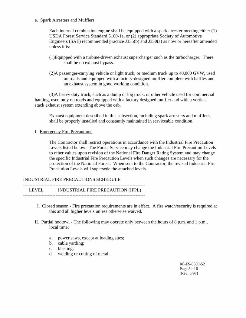
e. Spark Arresters and Mufflers
Each internal combustion engine shall be equipped with a spark arrester meeting either (1) USDA Forest Service Standard 5100-1a, or (2) appropriate Society of Automotive Engineers (SAE) recommended practice J335(b) and J350(a) as now or hereafter amended unless it is: (1)Equipped with a turbine-driven exhaust supercharger such as the turbocharger. There
shall be no exhaust bypass. (2)A passenger-carrying vehicle or light truck, or medium truck up to 40,000 GVW, used
on roads and equipped with a factory-designed muffler complete with baffles and an exhaust system in good working condition.
(3)A heavy duty truck, such as a dump or log truck, or other vehicle used for commercial
hauling, used only on roads and equipped with a factory designed muffler and with a vertical stack exhaust system extending above the cab.
Exhaust equipment described in this subsection, including spark arresters and mufflers, shall be properly installed and constantly maintained in serviceable condition.
f. Emergency Fire Precautions
The Contractor shall restrict operations in accordance with the Industrial Fire Precaution Levels listed below. The Forest Service may change the Industrial Fire Precaution Levels to other values upon revision of the National Fire Danger Rating System and may change the specific Industrial Fire Precaution Levels when such changes are necessary for the protection of the National Forest. When sent to the Contractor, the revised Industrial Fire Precaution Levels will supersede the attached levels.
INDUSTRIAL FIRE PRECAUTIONS SCHEDULE ------------------------------------------------------------------------------- LEVEL INDUSTRIAL FIRE PRECAUTION (IFPL) ------------------------------------------------------------------------------- I. Closed season - Fire precaution requirements are in effect. A fire watch/security is required at
this and all higher levels unless otherwise waived.
II. Partial hootowl - The following may operate only between the hours of 8 p.m. and 1 p.m., local time:
a. power saws, except at loading sites; b. cable yarding; c. blasting; d. welding or cutting of metal.
R6-FS-6300-52 Page 3 of 6 (Rev. 5/97)
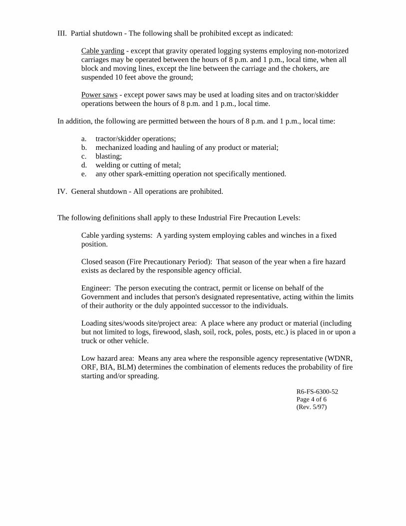
III. Partial shutdown - The following shall be prohibited except as indicated:
Cable yarding - except that gravity operated logging systems employing non-motorized carriages may be operated between the hours of 8 p.m. and 1 p.m., local time, when all block and moving lines, except the line between the carriage and the chokers, are suspended 10 feet above the ground; Power saws - except power saws may be used at loading sites and on tractor/skidder operations between the hours of 8 p.m. and 1 p.m., local time.
In addition, the following are permitted between the hours of 8 p.m. and 1 p.m., local time:
a. tractor/skidder operations; b. mechanized loading and hauling of any product or material; c. blasting; d. welding or cutting of metal; e. any other spark-emitting operation not specifically mentioned.
IV. General shutdown - All operations are prohibited.
The following definitions shall apply to these Industrial Fire Precaution Levels:
Cable yarding systems: A yarding system employing cables and winches in a fixed position. Closed season (Fire Precautionary Period): That season of the year when a fire hazard exists as declared by the responsible agency official. Engineer: The person executing the contract, permit or license on behalf of the Government and includes that person's designated representative, acting within the limits of their authority or the duly appointed successor to the individuals. Loading sites/woods site/project area: A place where any product or material (including but not limited to logs, firewood, slash, soil, rock, poles, posts, etc.) is placed in or upon a truck or other vehicle. Low hazard area: Means any area where the responsible agency representative (WDNR, ORF, BIA, BLM) determines the combination of elements reduces the probability of fire starting and/or spreading.
R6-FS-6300-52 Page 4 of 6 (Rev. 5/97)
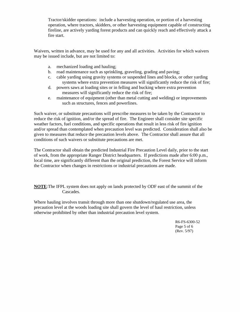
Tractor/skidder operations: include a harvesting operation, or portion of a harvesting operation, where tractors, skidders, or other harvesting equipment capable of constructing fireline, are actively yarding forest products and can quickly reach and effectively attack a fire start.
Waivers, written in advance, may be used for any and all activities. Activities for which waivers may be issued include, but are not limited to:
a. mechanized loading and hauling; b. road maintenance such as sprinkling, graveling, grading and paving; c. cable yarding using gravity systems or suspended lines and blocks, or other yarding
systems where extra prevention measures will significantly reduce the risk of fire; d. powers saws at loading sites or in felling and bucking where extra prevention
measures will significantly reduce the risk of fire; e. maintenance of equipment (other than metal cutting and welding) or improvements
such as structures, fences and powerlines.
Such waiver, or substitute precautions will prescribe measures to be taken by the Contractor to reduce the risk of ignition, and/or the spread of fire. The Engineer shall consider site specific weather factors, fuel conditions, and specific operations that result in less risk of fire ignition and/or spread than contemplated when precaution level was predicted. Consideration shall also be given to measures that reduce the precaution levels above. The Contractor shall assure that all conditions of such waivers or substitute precautions are met. The Contractor shall obtain the predicted Industrial Fire Precaution Level daily, prior to the start of work, from the appropriate Ranger District headquarters. If predictions made after 6:00 p.m., local time, are significantly different than the original prediction, the Forest Service will inform the Contractor when changes in restrictions or industrial precautions are made. NOTE:The IFPL system does not apply on lands protected by ODF east of the summit of the
Cascades. Where hauling involves transit through more than one shutdown/regulated use area, the precaution level at the woods loading site shall govern the level of haul restriction, unless otherwise prohibited by other than industrial precaution level system.
R6-FS-6300-52 Page 5 of 6 (Rev. 5/97)

8. Fire Tools
The Contractor shall furnish serviceable fire fighting tools in a readily accessible fire tool box or compartment of sound construction with a hinged lid and hasp so arranged that the box can be secured or sealed. The box shall be red and marked "Fire Tools" in letters one inch high. It shall contain a minimum of:
a. 2 axes or Pulaskis with a 32-inch handle; b. 3 adze eye hoes. One Pulaski may be substituted for 1 adze eye hoe; c. 3 long-handled, round point shovels, size "0" or larger.
9. Fire Security
When the Industrial Fire Precautions Level is "I" or higher, unless a waiver is granted, the Contractor shall designate a person who shall perform fire security services listed below on the project area and vicinity. The designated person shall be capable of operating the Contractor's communications and fire fighting equipment specified in the contract, excluding helicopters, and of directing the activities of the Contractor's personnel on forest fires. In lieu of having the designated person perform the required supervisory duties, the Contractor may provide another person meeting the qualifications stated above to direct the activities of Contractor's personnel and equipment during all fire fighting activities.
Services described shall be for at least 1 hour from the time the Contractor's operations are shut down. For the purposes of this provision, personnel servicing equipment, and their vehicles, who are not engaged in cutting or welding metal are excluded.
Fire security services shall consist of moving throughout the operation area or areas constantly looking, reporting, and taking suppression action on any fires detected. Where possible, the designated person shall observe inaccessible portions of helicopter operating areas from vantage points within or adjacent to project area.
10. Blasting
Whenever the Industrial Fire Precaution Level is "II" or greater, a fire security person equipped with a long-handled, round point, No. "0" or larger, shovel, and a five-gallon backpack pump can filled with water will stay at location of blast for 1 hour after blasting is done. Blasting may be suspended by Forest Service in writing, in an area of high rate of spread and resistance to control.
Fuses shall not be used for blasting. Explosive cords shall not be used without written permission of Forest Service, which may specify conditions under which such explosives may be used and precautions to be taken.
R6-FS-6300-52 Page 6 of 6 (Rev. 5/97)

USDA Forest Service - Pacific Northwest Region Fire Protection and Suppression Additional Fire Precautionary Measure 1 - Tank Truck The Contractor shall provide a tank truck or trailer containing not less than 300 gallons of water during yarding, loading, land clearing, right of way clearing, and mechanical treatment of slash. A tank truck or trailer will not be required if power saw falling and bucking is the only operation. Such tank truck or trailer shall be maintained in a serviceable condition and located within 10 minutes, round trip, from each project area during fire period and closed season. The tank truck or trailer shall be equipped with a pump capable of discharging 20 gallons of water per minute, using a ¼ inch nozzle tip, through a 50-foot length of rubber lined hose. In addition, 500 feet of serviceable fabric jacket rubber lined hose of not less than 1 inch outside diameter, fitted with a nozzle capable of discharging a straight stream of ¼ inch diameter and a spray pattern shall be immediately available for use. The tank, pump, and at least 250 feet of hose and nozzle shall be connected and ready for use at all times. If a trailer is used, it shall be equipped with a hitch to facilitate prompt movement. A serviceable tow vehicle shall be immediately available for attachment to the trailer and must meet the time requirements stated above. Such truck or trailer shall be equipped to operate for a minimum of 8 hours. Tank truck or trailer shall be available from the start of work to the end of the Fire Watch/Fire Security service.
R6-FS-6300-53 Additional Fire Precautionary Measure 2 - Communications The Contractor shall provide adequate two-way communication facilities to report a fire to the Forest Service within 15 minutes of detection. FCC regulations prohibit commercial use of Citizen Band (CB) radios. CB's are not considered adequate two-way communications. Such communications shall be operable during periods of operation of power driven equipment, including the time fire security is required.
R6-FS-6300-54

Attachment D.
Injury Report Form

LLOOSSSS RREEPPOORRTT && DDIIAAGGNNOOSSIISS
Employee Name _________________________________ Male Female SSN ________________________ DOB ____________
Address _________________________________ City & Zip ________________________ Clock # _________
(Optional) Marital Status_______ Spouse's Name________________________________________ # of Dependant Children __________
Date of Event _____________ Time __________ AM PM Report Date ______________ Time __________ AM PM
Department # ____________Exact Location _____________________________________ Home Phone # ________________________
Originated By ______________________________Title ____________________________ Date Hired _________ Wage __________
Title _________________________ Job at Time of Incident __________________________________ Time on this Job ___________
Time Began Work ________ Nature of Injury-(cut, burn, puncture) _____________________________ Body Part ___________________
What Harmed Employee (pipe, hammer, etc.) __________________ Date expected back ______________
Property Damaged _____________________________________________________________________________
Nature of Damage ____________________________ Work Order # _______________________________________
Repair/Replacement Cost: Estimated ________________________ Actual ___________________________________
DESCRIBE IN YOUR OWN WORDS HOW THE LOSS OCCURRED. (Must be completed by employee)
____________________________________________________________________________________________ ____________________________________________________________________________________________ ____________________________________________________________________________________________ ____________________________________________________________________________________________ _____________________________________________________________________________________________ _____________________________________________________________________________________________
TO BE COMPLETED BY SAFETY & HEALTH DEPARTMENT OR RESPONDING MEDICAL PERSONNEL DESCRIBE FIRST AID GIVEN ______________________________________________________________________________________________ _______________________________________________________________________________________________________________________
First Aid – On-Site First Aid – Off-Site Treated in Emergency Room? Yes No Hospitalized Overnight? Yes No Sutures Fracture Medication(s) ____________________________________________________________________
NAME OF TREATING PHYSICIAN AND/OR MEDICAL CENTER __________________________________________________________________
TO BE COMPLETED BY PERSON RESPONSIBLE FOR OSHA RECORDKEEPING INJURY ILLNESS OSHA RECORDABLE? Yes No Why ___________________________________________________
Lost Workday Restricted Duty Report Only Fatality? Yes No If yes, Date of Death ______________________________
PART
I BA
SIC
INFO
PA
RT II
INJU
RY
PART
III
PROP
ERTY
PART
IV
DES
CRIP
TION
OF
INCI
DENT
LLooccaattiioonn ______________________________________ SSeeccttiioonn II –– WWHHAATT HHAAPPPPEENNEEDD IInncciiddeenntt ## ______________ OOSSHHAA CCllaaiimm ## ____________
Part I contains basic, standard information which must be filled out for every report. Part II must be filled out for every injury loss, and the front page of this report must be turned into Safety & Health within 24 hours of the incident. A report must be made to the Workers Compensation Insurer within 3-days. Part III is for recording losses involving property damage. Part IV is a description of all events. Complete Parts I, II, and IV for injury events. Complete Parts I, III, and IV for property damage events. Section II on the backside of this form must be completed for every loss during the diagnosis review. Also, have the employee note the location of the pain on the Workers’ Compensation Pain Drawing form.
SEND TOP COPY OF FRONT TO SAFETY & HEALTH. Retain second copy of front and complete back. Return completed report to Safety & Health.

SSeeccttiioonn IIII –– BBEEHHAAVVIIOORRAALL AANNAALLYYSSIISS
Department Supervisors are to complete this section by conducting an interview with the employee involved in the incident. Each supervisor must record responses to each question in the space provided. Answers to the questions will most likely call for follow-up questions to obtain a better understanding of the response. (See instructions for completing this form in the file entitled “Loss Report & Diagnosis – Guidelines” in the Safety Cyber Library). THE FISHBONE ANALYSIS IS TO BE USED WITH THIS SECTION. 1. ARE THERE WORK/JOB INSTRUCTIONS FOR THIS JOB/TASK? Responses to Question: __________________________________________________________________________________________________ ______________________________________________________________________________________________________________________
2. WERE YOU DOING THE TASK AS YOU WERE TRAINED? PLEASE DESCRIBE TRAINING Responses to Question: __________________________________________________________________________________________________ ______________________________________________________________________________________________________________________
3. WHAT WERE THE POSITIVE RESULTS FOR THE METHOD YOU CHOSE? Responses to Question: __________________________________________________________________________________________________ ______________________________________________________________________________________________________________________ 4. DID YOU THINK THERE WAS A BETTER WAY TO PERFORM THE TASK? Responses to Question: __________________________________________________________________________________________________ ______________________________________________________________________________________________________________________
5. IS THERE ANYTHING ABOUT THE TASK THAT MAKES IT DIFFICULT FOR ANYONE TO COMPLETE CORRECTLY? Responses to Question: __________________________________________________________________________________________________ ______________________________________________________________________________________________________________________
6. SHOULD A HAZARD REPORT BE FILLED OUT? Responses to Question: __________________________________________________________________________________________________ ______________________________________________________________________________________________________________________
7. WERE THERE OTHER PRESSURES AT THE TIME THAT CAUSED SAFETY TO BE COMPROMISED? Responses to Question: __________________________________________________________________________________________________ ______________________________________________________________________________________________________________________
Section III – ADMINISTRATIVE DETAILS WHAT TYPE OF EVENTS CONTRIBUTED THE MOST TO THE INJURY? _____ Factors away from work _____ Non-Production tasks _____ Production tasks Loss Severity Potential: __ minor __ major __ serious __ catastrophic
Probable Occurrence Rate: __ negligible __ low __ moderate __ high Cost of Control: __ minor __ low __ medium __ high Degree of Control Achieved: __ low __ moderate __ substantial __ complete
Names of persons participating in the Incident Diagnosis. These persons are responsible for assuring that the "Actions to Prevent a Recurrence" are completed. (All Positions must sign)
Employee _______________________ Date _______________ Supervisor _______________________ Date _____________ Manager ________________________ Date _______________ Safety Coor.______________________ Date _____________ Other ____________________________________________ Title ___________________________ Date _____________ Other ____________________________________________ Title ___________________________ Date _____________
ACTIONS TO PREVENT A RECURRENCE
ACTION #1: __________________________________________ PERSON RESPONSIBLE: _______________ PROJECTED COMP. DATE______
ACTION #2: __________________________________________ PERSON RESPONSIBLE: _______________ PROJECTED COMP. DATE______ ACTION #3: __________________________________________ PERSON RESPONSIBLE: _______________ PROJECTED COMP. DATE______
This Diagnosis must be reviewed and signed by the site manager
___________________________________________________________________________________ Date: _________________________________________
ISRS Ref: 5.1; 5.5 Rev Date: 1/02, 10/02, 5/03, 6/03, 7/04;3/05
ASSE
SSME
NT
OF
RISK

Appendix B.
Final Mill Creek Fish Presence and Fish Passage Barrier Assessment Memo

TECHNICAL MEMORANDUM DATE: October 30, 2007 TO: Rod Lentz – U.S. Forest Service FROM: Rone Brewer – Sound Ecological Endeavors Dustin Wasley – Cascade Earth Sciences
SUBJECT: Mill Creek Fish Presence and Fish Passage Barrier Assessment - Azurite Mine, Mazama, Washington
On October 2, 2007, Sound Ecological Endeavors (SEE) and Cascade Earth Sciences (CES) walked the entire length of Mill Creek from the Azurite Mine (Site) to the confluence with Canyon Creek. The goal was to identify fish passage barriers and determine fish presence. Heavy rain and wet snowfall occurred before and during the survey. Water flow in the creek was continuous (i.e., did not disappear into the streambed) and increased in volume with distance downstream from the mine. However, based on observed areas of high volume instream gravel deposits, it was deemed likely that the streambed is dry in places during the summer/fall. While proceeding downstream from the Site, SEE and CES identified five permanent and nine temporary fish passage barriers as shown in Figure 1. Permanent fish passage barriers are those expected to remain within Mill Creek over very long periods of time (i.e., tens to hundreds of years) and are typically waterfalls with a bedrock substrate. Temporary barriers are those that may change seasonally or annually, often created by accumulations of woody debris; or those that may be barriers to small fish but not larger adult fish due to height of, or seasonally limited flow over, the barrier. Pictures of the fish barriers are provided in the attached log of photographs. Fourteen inch square dip nets with ¼ inch mesh were used in an attempt to collect and identify fish in Mill Creek. The dip nets were opportunistically pulled through pool and riffle habitats along the entire length of the creek. No fish were caught. Only three very small unidentified fish were observed, all downstream of Fish Barrier 05 which is approximately 2.4 miles downstream from the Site. Given the large log jam at Fish Barrier 05 and other instream woody debris, it is apparent that extremely high volumes of water and debris scour Mill Creek each spring. Then, in the fall, flow becomes very low with likely areas of dry streambed. Because of these conditions, and the presence of other bedrock fish passage barriers, it is deemed unlikely that fish have ever migrated upstream of Fish Barrier 04 (two miles downstream from Site) and most recently have not been able to migrate upstream of Fish Barrier 05. In addition, no records were found during the earlier Site Inspection (CES, 2004) indicating that fish had been transplanted into the upper reaches of Mill Creek. Thus, fish are unlikely to have ever inhabited Mill Creek in the within two miles of Site. RB:DGW/sjr PN: 2723031 Doc: Tech Memo - Azurite Fish Barrier 10-26-07.doc

FIGURE 1
MILL CREEK FISH PASSAGE BARRIERS


ATTACHMENT A
LOG OF PHOTOGRAPHS

Fish Barrier 01
Temp. Fish Barrier 01

Temp. Fish Barrier 02
Temp. Fish Barrier 03

Temp. Fish Barrier 04
Fish Barrier 02

Fish Barrier 03
Temp. Fish Barrier 05

Temp. Fish Barrier 06
Fish Barrier 04

Temp. Fish Barrier 07
Temp. Fish Barrier 08

Fish Barrier 05
Temp. Fish Barrier 09

Appendix C.
Final Engineering Assessment: Slope Stability Memo (2007)/ Supplemental Geotechnical Analysis - Soil Cover Stability Analysis (2009)/
Supplement Geotechnical Memo-Correspondence (2011)

December 20, 2007
Cascade Earth Sciences 12720 East Nora Avenue, Suite A Spokane, Washington 99216
Attention: Dustin Wasley, PE
Subject: Geotechnical Engineering Services Azurite Mine Mt. Baker-Snoqualmie National Forest File No. 0347-076-01
INTRODUCTION
This letter transmits the results of our field explorations and slope stability analyses for the proposed remediation alternatives in support of disposal and capping of mine tailings and waste rock at the Azurite Mine site, herein referred to as the “Site”. The Azurite Mine is located within the Mt. Baker-Snoqualmie National Forest in Whatcom County, Washington, approximately as shown on the Vicinity Map, Figure 1. The Site is located within the Mill Creek drainage, a U-shaped glacial valley surrounded by rugged mountainous terrain. There are two main waste rock piles, located on the east-facing slopes of the drainage, which encroach upon Mill Creek. The remains of the mill and a large tailings pile are located on the opposite side of the creek from the waste rock piles. The approximate locations of the existing site features are presented in the Site Plan, Figure 2.
We understand that MFG, Inc. (MFG) conducted an engineering evaluation of remediation alternatives for the Site. One alternative developed by MFG included excavating the waste rock piles and placing the material on top of the tailings pile, followed by construction of a soil cap on top of the relocated waste rock. MFG also included a retaining wall at the base of the tailings pile to retain the waste rock as part of their preliminary design. As part of MFG’s preliminary design, they performed slope stability analyses of the existing and proposed slopes.
Our services included visiting the site and collecting samples of the tailings and native soil; reviewing MFG’s preliminary design from a slope stability standpoint; and providing an alternative disposal location for the waste rock stockpile. Our services were completed in general accordance with our Subcontractor Agreement for Services dated September 20, 2007.
SITE CONDITIONS
GENERAL
We completed a limited site investigation in conjunction with Cascade Earth Sciences (CES) on October 1 and 3, 2007. Our investigation included six test pits (TP-1 through TP-6) in the vicinity of the existing tailings pile at the approximate locations shown on Figure 2. The test pits were excavated to depths in the range of about 9 to 13½ feet below existing site grade.

Cascade Earth Sciences, Inc. December 20, 2007 Page 2
File No. 0347-076-01
Representative soil samples from the test pits, as well as soil samples obtained from test pits excavated in the waste rock piles under the supervision of CES, were returned to our laboratory for review and testing. Detailed descriptions of our site exploration and laboratory testing programs along with test pit logs are presented in Attachment A.
SURFACE CONDITIONS
The existing tailings pile is sloped at inclinations in the range of about 2H:1V (horizontal to vertical) to about 3H:1V. Steeper slopes generally are located on the north portions of the tailings pile, with site inclinations generally decreasing in steepness towards the south. The mill site area is located to the south of the tailings pile, and has been graded and benched. The tailings pile is barren, as is most of the mill site area. Surrounding vegetation consists of coniferous trees and an understory of brush. A seep is located downgradient from the tailings pile adjacent to an existing access road.
SUBSURFACE CONDITIONS
General
Test pit TP-1 was excavated near a topographical “bowl” feature in the tailings pile, where it appears that additional material could be placed with relatively limited grading or benching requirements. Test pits TP-2 through TP-4 were excavated in the general vicinity of the proposed retaining wall as presented in the plans developed by MFG. Test pits TP-5 and TP-6 were excavated outside of the tailings pile in order to characterize shallow soil in areas for an alternative location for placement of the waste rock. Test pits also were excavated within the waste rock piles and observed by CES. Bulk samples from the waste rock pile test pits were provided to us by CES. The following paragraphs provide a brief description of the subsurface conditions at the locations of our test pits.
Tailings
Test pits TP-1 through TP-4 were advanced through the tailings near the bottom of the existing tailings pile. The tailings pile consists of fine-grained soil (silt and clay) that is weakly to strongly cemented. At the locations of our test pits, we observed that the consistency of the tailings in an undisturbed condition is very stiff to hard. We also observed that when the tailings were disturbed and subjected to moisture, they became soft. Based on discussions with CES, We understand that maximum thickness of the tailings pile is on the order of about 15 feet.
Native Soil
At the locations of our test pits, the native soil generally consisted of fine to coarse angular to subangular gravel with variable amounts of silt, sand, cobbles and occasional boulders. Results of grain-size analyses indicate that the fines (silt- and clay-sized soil particles passing the U.S. No. 200 sieve) content of the native soil was in the range of about 7 to 19 percent. Based on difficulty of excavation, results of probing and observation of caving within test pits, the relative density of most of the native soil appears to be medium dense to dense. However, at the locations of test pits TP-1 and TP-3, we observed a buried topsoil layer at and below the base of the tailings pile. At the locations of test pits TP-3 and TP-4, we also observed a layer of loose to very loose poorly graded gravel and cobbles.
Waste Rock
Samples of waste rock obtained from test pits conducted under the supervision of CES were returned to our laboratory for review and testing. Results of laboratory testing indicate that the waste rock generally

Cascade Earth Sciences, Inc. December 20, 2007 Page 3
File No. 0347-076-01
consists of fine to coarse angular to subangular gravel with silt and sand. The fines content of the waste rock samples was in the range of about 7 to 13 percent.
GROUNDWATER
We encountered slight groundwater seepage at the location of test pit TP-6 at a depth of about 5 feet below current ground surface. The seep appeared to be limited in extent. Seepage was limited to one corner of the test pit, and groundwater was not observed below the elevation of the seepage.
SLOPE STABILITY ANALYSES
GENERAL
We used the computer program Slope/W to analyze the stability of existing and proposed slopes in support of proposed grading for the waste rock repository. In particular, we analyzed the global stability of the existing tailings pile, and the proposed waste rock placement designed by MFG. We also analyzed global stability of existing slopes and an alternative waste rock placement plan within the mill area.
ENGINEERING PARAMETERS OF SITE SOILS
We developed engineering parameters of site soil units based on the results of our site exploration and laboratory analyses. In general, our engineering parameters for the site soil units and conditions are based on the following assumptions.
• Tailings at the site will be left in an undisturbed state. Disturbance to the tailing will result in significant loss of cohesive strength and reduction of shear strength.
• The poorly graded loose gravel and cobble deposit encountered in test pits TP-3 and TP-4 likely consists of colluvium and resulted in our selection of lower engineering parameters than what would be representative for the medium dense to dense soil encountered elsewhere on site.
• Because layers of poorly graded colluvium could be present at other locations and at depths below the limits of our excavations, we used lower engineering parameters for all of the native soil profile where it was encountered at the base of the tailings pile.
• We used engineering parameters representative of the medium dense to dense soil for analyses in the vicinity of test pits TP-5 and TP-6. However, the use of these higher values was limited to the depth of our excavations.
• Waste rock will be compacted to a minimum density of 90 percent of maximum dry density based on the American Society for Testing and Materials D 698 test procedure.
• A phreatic water surface is present approximately 40 feet below the existing ground surface.
The parameters used in our slope stability analyses are presented in Table 1.
Table 1. Engineering Parameters of Site Soils
Soil Type Moist Unit
Weight (pcf) Saturated unit Weight
(pcf) Friction Angle
(deg) Cohesion
(psf)
Waste Rock 120 125 33 0
Tailings 110 115 0 1,500
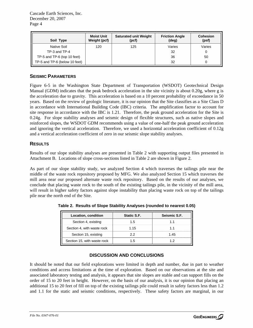
Cascade Earth Sciences, Inc. December 20, 2007 Page 4
File No. 0347-076-01
Soil Type Moist Unit
Weight (pcf) Saturated unit Weight
(pcf) Friction Angle
(deg) Cohesion
(psf)
Native Soil
TP-3 and TP-4
TP-5 and TP-6 (top 10 feet)
TP-5 and TP-6 (below 10 feet)
120 125 Varies
32
36
32
Varies
0
50
0
SEISMIC PARAMETERS
Figure 6-5 in the Washington State Department of Transportation (WSDOT) Geotechnical Design Manual (GDM) indicates that the peak bedrock acceleration in the site vicinity is about 0.20g, where g is the acceleration due to gravity. This acceleration is based on a 10 percent probability of exceedance in 50 years. Based on the review of geologic literature, it is our opinion that the Site classifies as a Site Class D in accordance with International Building Code (IBC) criteria. The amplification factor to account for site response in accordance with the IBC is 1.21. Therefore, the peak ground acceleration for the Site is 0.24g. For slope stability analyses and seismic design of flexible structures, such as native slopes and reinforced slopes, the WSDOT GDM recommends using a value of one-half the peak ground acceleration and ignoring the vertical acceleration. Therefore, we used a horizontal acceleration coefficient of 0.12g and a vertical acceleration coefficient of zero in our seismic slope stability analyses.
RESULTS
Results of our slope stability analyses are presented in Table 2 with supporting output files presented in Attachment B. Locations of slope cross-sections listed in Table 2 are shown in Figure 2.
As part of our slope stability study, we analyzed Section 4 which traverses the tailings pile near the middle of the waste rock repository proposed by MFG. We also analyzed Section 15 which traverses the mill area near our proposed alternate waste rock repository. Based on the results of our analyses, we conclude that placing waste rock to the south of the existing tailings pile, in the vicinity of the mill area, will result in higher safety factors against slope instability than placing waste rock on top of the tailings pile near the north end of the Site.
Table 2. Results of Slope Stability Analyses (rounded to nearest 0.05)
Location, condition Static S.F. Seismic S.F.
Section 4, existing 1.5 1.1
Section 4, with waste rock 1.15 1.1
Section 15, existing 2.2 1.45
Section 15, with waste rock 1.5 1.2
DISCUSSION AND CONCLUSIONS
It should be noted that our field explorations were limited in depth and number, due in part to weather conditions and access limitations at the time of exploration. Based on our observations at the site and associated laboratory testing and analysis, it appears that site slopes are stable and can support fills on the order of 15 to 20 feet in height. However, on the basis of our analysis, it is our opinion that placing an additional 15 to 20 feet of fill on top of the existing tailings pile could result in safety factors less than 1.2 and 1.1 for the static and seismic conditions, respectively. These safety factors are marginal, in our


Site
Whatcom County
Skagit County
Okanogan County
Brus h CreekBrush Creek
µSeatle
§̈¦5 4,000 4,0000
Feet
Data Sources: ESRI Data & Maps, Street Maps 2005
Notes:1. The locations of all features shown are approximate.2. This drawing is for information purposes. It is intended to assist in showing features discussed in an attached document. GeoEngineers, Inc. can not guarantee the accuracy and content of electronic files. The master file is stored by GeoEngineers, Inc. and will serve as the official record of this communication.3. It is unlawful to copy or reproduce all or any part thereof, whether for personal use or resale, without permission.
Transverse Mercator, Zone 10 N North, North American Datum 1983North arrow oriented to grid northOf
fice:
SPOK
Path:
P:\0
0\034
7076
\01\G
IS\MX
Ds\03
4707
601F
igure1
.mxd
Map R
evise
d: De
cemb
er 19
, 200
7
Vicinity Map
Figure 1
Azurite MineMt. Baker-Snoqualmie National Forest, Washington
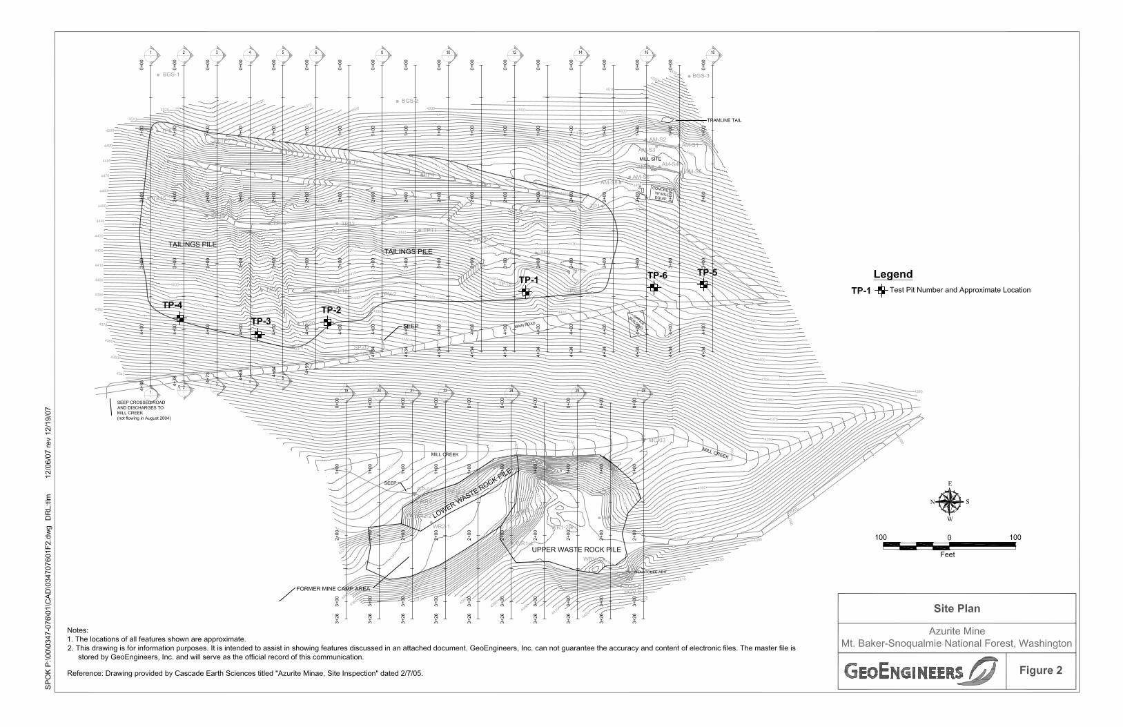

ATTACHMENT A SUBSURFACE EXPLORATIONS AND LABORATORY
TESTING

File No.0347-076-01 Page A-1 December 20, 2007
ATTACHMENT A SUBSURFACE EXPLORATIONS AND LABORATORY TESTING
SUBSURFACE EXPLORATIONS
Soil and groundwater conditions at the subject site were explored on October 3, 2007 by excavating six test pits (TP-1 through TP-6) at the approximate locations shown on Figure 2. The test pits were excavated with a small tracked excavator under subcontract to CES. The locations of the explorations were established by pacing and taping from existing site features and should be considered approximate.
The explorations were monitored by an engineer from our firm who examined and classified the soil encountered and obtained representative samples. Soil encountered in the test pits was classified in general accordance with ASTM D 2488 and the classification chart listed in Key to Exploration Logs, Figure A-1. Logs of the test pits are presented in Log of Test Pits, Figures A-2 through A-7. The logs are based on interpretation of the field and laboratory data, and indicate the depth at which subsurface materials or their characteristics change, although these changes might actually be gradual.
LABORATORY TESTING
Soil samples obtained from test pits TP-1 through TP-6, as well as samples from test pits excavated in the waste rock piles under the supervision of CES [denoted as Lower Waste Rock (LWR-1 and LWR-2) and Upper Waste Rock (UWR-1 and UWR-2)], were returned to our laboratory for further examination and testing. Gradation tests (ASTM C136) were accomplished on representative soil samples. Results of ASTM C136 analyses are presented in Sieve Analysis Results, Figures A-8 through A-10.
Selected samples also were tested to estimate their natural moisture content in general accordance with ASTM D2216. Results are presented on the exploration logs at the respective sample depths.
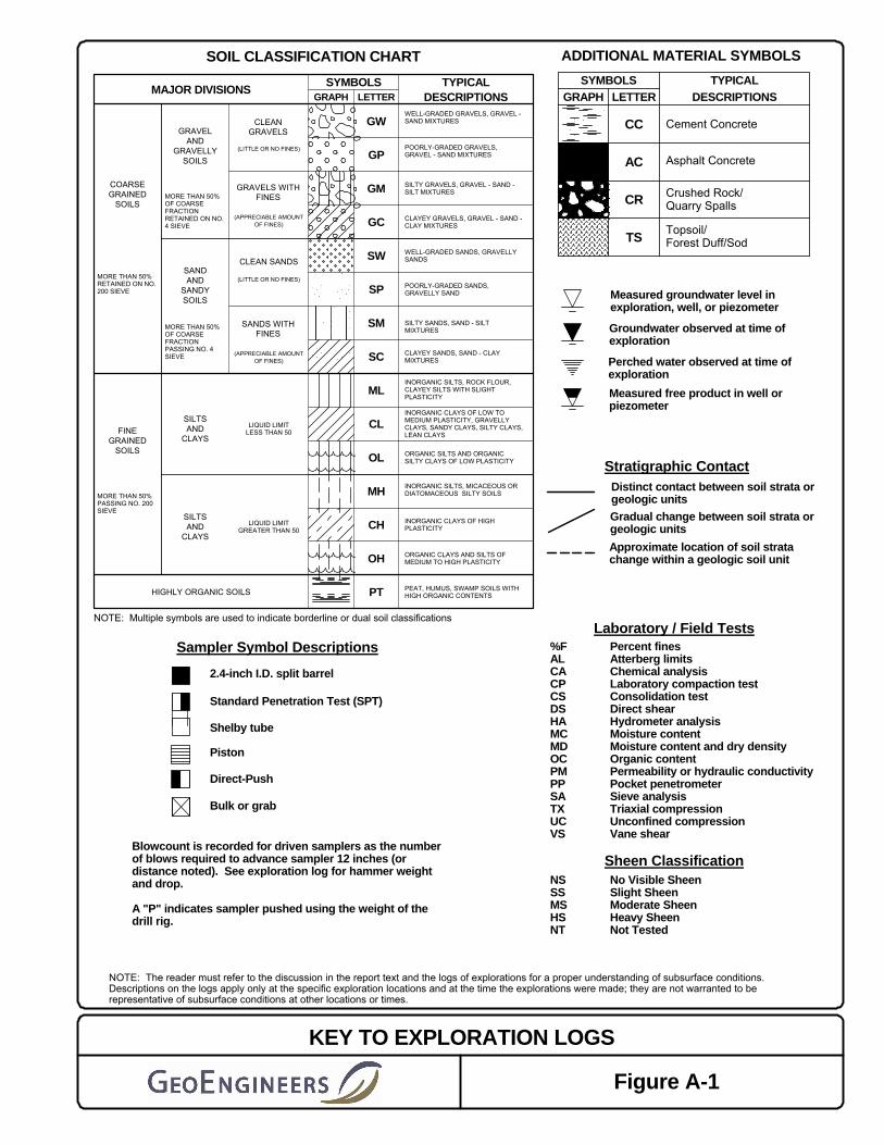
GC
PT
OH
CH
MH
OL
ORGANIC CLAYS AND SILTS OFMEDIUM TO HIGH PLASTICITY
MORE THAN 50%PASSING NO. 200SIEVE
MORE THAN 50%OF COARSEFRACTIONPASSING NO. 4SIEVE
GM
GP
GW
DESCRIPTIONSTYPICAL
LETTERGRAPH
(APPRECIABLE AMOUNTOF FINES)
SYMBOLSMAJOR DIVISIONS
WELL-GRADED SANDS, GRAVELLYSANDSCLEAN SANDS
GRAVELS WITHFINES
CLEANGRAVELS
HIGHLY ORGANIC SOILS
SILTSAND
CLAYS
SILTSAND
CLAYS
SANDAND
SANDYSOILS
MORE THAN 50%OF COARSEFRACTIONRETAINED ON NO.4 SIEVE
MORE THAN 50%RETAINED ON NO.200 SIEVE
GRAVELAND
GRAVELLYSOILS
(LITTLE OR NO FINES)
FINEGRAINED
SOILS
COARSEGRAINED
SOILS
NOTE: Multiple symbols are used to indicate borderline or dual soil classifications
SW
CL
WELL-GRADED GRAVELS, GRAVEL -SAND MIXTURES
POORLY-GRADED SANDS,GRAVELLY SAND
INORGANIC SILTS, ROCK FLOUR,CLAYEY SILTS WITH SLIGHTPLASTICITY
INORGANIC SILTS, MICACEOUS ORDIATOMACEOUS SILTY SOILS
SILTY GRAVELS, GRAVEL - SAND -SILT MIXTURES
(APPRECIABLE AMOUNTOF FINES)
SOIL CLASSIFICATION CHART
LIQUID LIMITGREATER THAN 50
LIQUID LIMITLESS THAN 50
SANDS WITHFINES
SP
PEAT, HUMUS, SWAMP SOILS WITHHIGH ORGANIC CONTENTS
INORGANIC CLAYS OF HIGHPLASTICITY
(LITTLE OR NO FINES)
ORGANIC SILTS AND ORGANICSILTY CLAYS OF LOW PLASTICITY
INORGANIC CLAYS OF LOW TOMEDIUM PLASTICITY, GRAVELLYCLAYS, SANDY CLAYS, SILTY CLAYS,LEAN CLAYS
CLAYEY SANDS, SAND - CLAYMIXTURES
SILTY SANDS, SAND - SILTMIXTURES
CLAYEY GRAVELS, GRAVEL - SAND -CLAY MIXTURES
POORLY-GRADED GRAVELS,GRAVEL - SAND MIXTURES
ML
SC
SM
Shelby tube
ADDITIONAL MATERIAL SYMBOLS
KEY TO EXPLORATION LOGS
Figure A-1
AC
Cement Concrete
2.4-inch I.D. split barrel
NOTE: The reader must refer to the discussion in the report text and the logs of explorations for a proper understanding of subsurface conditions.Descriptions on the logs apply only at the specific exploration locations and at the time the explorations were made; they are not warranted to berepresentative of subsurface conditions at other locations or times.
Perched water observed at time ofexploration
DESCRIPTIONS
No Visible SheenSlight SheenModerate SheenHeavy SheenNot Tested
NSSSMSHSNT
LETTER
Sampler Symbol Descriptions
GRAPHSYMBOLS TYPICAL
CC
CR
Stratigraphic Contact
Approximate location of soil stratachange within a geologic soil unit
Distinct contact between soil strata orgeologic unitsGradual change between soil strata orgeologic units
Measured free product in well orpiezometer
Topsoil/Forest Duff/Sod
Direct-Push
Crushed Rock/Quarry Spalls
TS
Sheen Classification
Laboratory / Field Tests
Blowcount is recorded for driven samplers as the numberof blows required to advance sampler 12 inches (ordistance noted). See exploration log for hammer weightand drop.
A "P" indicates sampler pushed using the weight of thedrill rig.
%FALCACPCSDSHAMCMDOCPMPPSATXUCVS
Percent finesAtterberg limitsChemical analysisLaboratory compaction testConsolidation testDirect shearHydrometer analysisMoisture contentMoisture content and dry densityOrganic contentPermeability or hydraulic conductivityPocket penetrometerSieve analysisTriaxial compressionUnconfined compressionVane shear
Bulk or grab
Piston
Standard Penetration Test (SPT)
Groundwater observed at time ofexploration
Asphalt Concrete
Measured groundwater level inexploration, well, or piezometer

SA
Orange cemented silty clay with sand (oxidized tailings) (undisturbedstate: very stiff to hard, PP > 4 tsf; disturbed state: very soft, PP 0-1tsf, moist to wet)
Gray cemented silt (partially oxidized to unoxidized tailings)(undisturbed state: very stiff to hard, PP > 4 tsf; disturbed state: verysoft, PP 0-1 tsf, moist)
Brown to dark brown silty fine to coarse angular to subangular gravelwith sand and cobbles (reworked native soil mixed with tailings in theupper 2 to 4 feet) (dense, moist)
Dark brown to black silty fine to coarse angular to subangular gravelwith sand and organic matter (loose, moist) (buried topsoil layer)
Test pit completed at approximately 11 foot depthNo groundwater seepage observedModerate caving observed
Note: cementation most intense in upper 1 to 4 feet, decreases withdepth, cementation consists of ferracrete and gypsum
1
2 22
CL/ML
ML
GM
TS
Equipment: Not measured
Gra
phic
Log
Logged by:10/03/07
OTHER TESTSAND NOTES
Notes: See Figure A-1 for explanation of symbols.
0
5
10
15
20
25
Gro
upS
ymbo
l
Sam
ple
Num
ber
DRLE
leva
tion
feet
Moi
stur
eC
onte
nt %MATERIAL DESCRIPTION
Surface Elevation (ft):D
epth
feet
Date Excavated:
Sam
ple
Excavator
Sheet 1 of 1
LOG OF TEST PIT TP-1Project:Project Location:Project Number:
Mt. Baker-Snoqualmie National Forest, WashingtonAzurite Mine
0347-076-01Figure: A- 2
V6_
GTT
PIT
P:\0
0\03
4707
6\01
\FIN
ALS
\034
7076
01.G
PJ
GE
IV6_
1.G
DT
12/
19/0
7

SA
Approximately 2 inches orange silty clay with sand (oxidized tailings)(undisturbed state: very stiff to hard, PP > 4 tsf; disturbed state: verysoft, PP 0-1 tsf) (moist to wet)
Gray cemented silt (partially oxidized to unoxidized tailings)(undisturbed state: very stiff to hard, PP > 4 tsf; disturbed state: verysoft to medium stiff, PP 0-2 tsf; moist)
Approximately 6-inch-thick layer rust colored oxidized tailings(cemented) (stiff to hard)
Dark brown fine to coarse gravel with silt, sand, cobbles and occasionalorganic matter (medium dense, moist) (upper 1 to 2 feet weaklycemented)
Grades to grayish brown in color
Test pit completed at approximately 9 foot depthNo groundwater seepage observedNo caving observed
1
2 26
CL/ML
ML
MLGP-GM
Equipment: Not measured
Gra
phic
Log
Logged by:10/03/07
OTHER TESTSAND NOTES
Notes: See Figure A-1 for explanation of symbols.
0
5
10
15
20
25
Gro
upS
ymbo
l
Sam
ple
Num
ber
DRLE
leva
tion
feet
Moi
stur
eC
onte
nt %MATERIAL DESCRIPTION
Surface Elevation (ft):D
epth
feet
Date Excavated:
Sam
ple
Excavator
Sheet 1 of 1
LOG OF TEST PIT TP-2Project:Project Location:Project Number:
Mt. Baker-Snoqualmie National Forest, WashingtonAzurite Mine
0347-076-01Figure: A- 3
V6_
GTT
PIT
P:\0
0\03
4707
6\01
\FIN
ALS
\034
7076
01.G
PJ
GE
IV6_
1.G
DT
12/
19/0
7

Orange silty clay with sand (oxidized tailings) (undisturbed state: verystiff to hard; disturbed state: very soft)
Light gray tailings (mostly gypsum) (undisturbed state: hard; disturbedstate: soft, moist)
Gray cemented silt (partially oxidized to unoxidized tailings)(undisturbed state: very stiff to hard; disturbed state: soft, moist)
Approximately 6 inches dark brown silty fine to coarse sand with graveland organic matter (buried topsoil layer)
Brown silty fine to coarse angular to subangular gravel with sand andcobbles (partially cemented ) (dense, moist)
Brown fine to coarse angular gravel with cobbles (loose, moist)
Test pit completed at approximately 13 1/2 foot depthNo groundwater seepage observedSevere caving observed below approximately 9 1/2 foot depth
ML/CL
MLGY
ML
TSGM
GP
Equipment: Not measured
Gra
phic
Log
Logged by:10/03/07
OTHER TESTSAND NOTES
Notes: See Figure A-1 for explanation of symbols.
0
5
10
15
20
25
Gro
upS
ymbo
l
Sam
ple
Num
ber
DRLE
leva
tion
feet
Moi
stur
eC
onte
nt %MATERIAL DESCRIPTION
Surface Elevation (ft):D
epth
feet
Date Excavated:
Sam
ple
Excavator
Sheet 1 of 1
LOG OF TEST PIT TP-3Project:Project Location:Project Number:
Mt. Baker-Snoqualmie National Forest, WashingtonAzurite Mine
0347-076-01Figure: A- 4
V6_
GTT
PIT
P:\0
0\03
4707
6\01
\FIN
ALS
\034
7076
01.G
PJ
GE
IV6_
1.G
DT
12/
19/0
7

Orange silty clay with sand (oxidized tailings) (undisturbed state: verystiff to hard; disturbed state: soft, moist)
Gray cemented silt (partially oxidized to unoxidized tailings)(undisturbed state: very stiff to hard; disturbed state: soft, moist)
Brown silty fine to coarse angular to subangular gravel with sand andcobbles (dense, moist) (weakly cemented upper 2 to 4 feet,cementation decreases with depth)
Brown fine to coarse angular to subangular gravel with cobbles andboulders (loose, moist)
Test pit completed at approximately 9 1/2 foot depthNo groundwater seepage observedSevere caving observed below approximately 7 foot depth
1
2
ML/CL
ML
GM
GP
Equipment: Not measured
Gra
phic
Log
Logged by:10/03/07
OTHER TESTSAND NOTES
Notes: See Figure A-1 for explanation of symbols.
0
5
10
15
20
25
Gro
upS
ymbo
l
Sam
ple
Num
ber
DRLE
leva
tion
feet
Moi
stur
eC
onte
nt %MATERIAL DESCRIPTION
Surface Elevation (ft):D
epth
feet
Date Excavated:
Sam
ple
Excavator
Sheet 1 of 1
LOG OF TEST PIT TP-4Project:Project Location:Project Number:
Mt. Baker-Snoqualmie National Forest, WashingtonAzurite Mine
0347-076-01Figure: A- 5
V6_
GTT
PIT
P:\0
0\03
4707
6\01
\FIN
ALS
\034
7076
01.G
PJ
GE
IV6_
1.G
DT
12/
19/0
7

SA
SA
Orangish brown fine to coarse angular to subangular gravel with silt,sand, cobbles and occasional boulders (medium dense to dense, moist)
Test pit completed at approximately 10 foot depthNo groundwater seepage observedNo caving observed
1
2
20
11
GP-GM
Equipment: Not measured
Gra
phic
Log
Logged by:10/03/07
OTHER TESTSAND NOTES
Notes: See Figure A-1 for explanation of symbols.
0
5
10
15
20
25
Gro
upS
ymbo
l
Sam
ple
Num
ber
DRLE
leva
tion
feet
Moi
stur
eC
onte
nt %MATERIAL DESCRIPTION
Surface Elevation (ft):D
epth
feet
Date Excavated:
Sam
ple
Excavator
Sheet 1 of 1
LOG OF TEST PIT TP-5Project:Project Location:Project Number:
Mt. Baker-Snoqualmie National Forest, WashingtonAzurite Mine
0347-076-01Figure: A- 6
V6_
GTT
PIT
P:\0
0\03
4707
6\01
\FIN
ALS
\034
7076
01.G
PJ
GE
IV6_
1.G
DT
12/
19/0
7
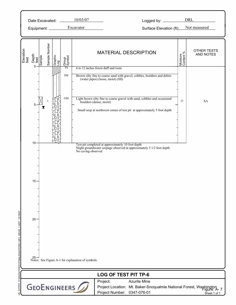
SA
6 to 12 inches forest duff and roots
Brown silty fine to coarse sand with gravel, cobbles, boulders and debris(water pipes) (loose, moist) (fill)
Light brown silty fine to coarse gravel with sand, cobbles and occasionalboulders (dense, moist)
Small seep at northwest corner of test pit at approximately 5 foot depth
Test pit completed at approximately 10 foot depthSlight groundwater seepage observed at approximately 5 1/2 foot depthNo caving observed
1 21
TS
SM
GM
Equipment: Not measured
Gra
phic
Log
Logged by:10/03/07
OTHER TESTSAND NOTES
Notes: See Figure A-1 for explanation of symbols.
0
5
10
15
20
25
Gro
upS
ymbo
l
Sam
ple
Num
ber
DRLE
leva
tion
feet
Moi
stur
eC
onte
nt %MATERIAL DESCRIPTION
Surface Elevation (ft):D
epth
feet
Date Excavated:
Sam
ple
Excavator
Sheet 1 of 1
LOG OF TEST PIT TP-6Project:Project Location:Project Number:
Mt. Baker-Snoqualmie National Forest, WashingtonAzurite Mine
0347-076-01Figure: A- 7
V6_
GTT
PIT
P:\0
0\03
4707
6\01
\FIN
ALS
\034
7076
01.G
PJ
GE
IV6_
1.G
DT
12/
19/0
7

Sieve Analysis Results
Figure A-8
Azurite Mine Mt. Baker-Snoqualmie National Forest, Washington
SPO:\00\0347-076\01\finals\034707601s.ppt 12/18/07 DRL:tlm
Note: This report may not be reproduced, except in full, without written approval of GeoEngineers, Inc. Test results are applicable only to the specific sample on which they were performed, and should not be interpreted as representative of any other samples obtained at other times, depths or locations, or generated by separate operations or processes.
SYMBOLEXPLORATION
NUMBERSAMPLE
DEPTH (FEET) SOIL CLASSIFICATION
TP-1
TP-2
TP-5
4
8
4
Silty fine to coarse gravel with sand
Fine to coarse gravel with silt and sand
Fine to coarse gravel with silt and sand
SANDSILT OR CLAYCOBBLES
GRAVEL
COARSE MEDIUM FINECOARSE FINE
U.S. STANDARD SIEVE SIZE
0
10
20
30
40
50
60
70
80
90
100
0.0010.010.11101001000
GRAIN SIZE IN MILLIMETERS
PE
RC
EN
T P
AS
SIN
G B
Y W
EIG
HT
3/8”3” 1.5” #4 #10 #20 #200#40 #60 #1003/4”
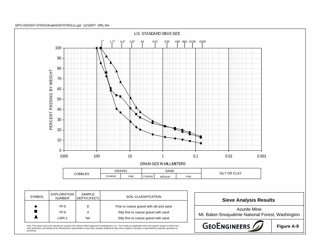
Sieve Analysis Results
Figure A-9
Azurite Mine Mt. Baker-Snoqualmie National Forest, Washington
SPO:\00\0347-076\01\finals\034707601s1.ppt 12/18/07 DRL:tlm
Note: This report may not be reproduced, except in full, without written approval of GeoEngineers, Inc. Test results are applicable only to the specific sample on which they were performed, and should not be interpreted as representative of any other samples obtained at other times, depths or locations, or generated by separate operations or processes.
SYMBOLEXPLORATION
NUMBERSAMPLE
DEPTH (FEET) SOIL CLASSIFICATION
TP-5
TP-6
LWR-1
8
4
NA
Fine to coarse gravel with silt and sand
Silty fine to coarse gravel with sand
Silty fine to coarse gravel with sand
SANDSILT OR CLAYCOBBLES
GRAVEL
COARSE MEDIUM FINECOARSE FINE
U.S. STANDARD SIEVE SIZE
0
10
20
30
40
50
60
70
80
90
100
0.0010.010.11101001000
GRAIN SIZE IN MILLIMETERS
PE
RC
EN
T P
AS
SIN
G B
Y W
EIG
HT
3/8”3” 1.5” #4 #10 #20 #200#40 #60 #1003/4”

Sieve Analysis Results
Figure A-10
Azurite Mine Mt. Baker-Snoqualmie National Forest, Washington
SPO:\00\0347-076\01\finals\034707601s2.ppt 12/18/07 DRL:tlm
Note: This report may not be reproduced, except in full, without written approval of GeoEngineers, Inc. Test results are applicable only to the specific sample on which they were performed, and should not be interpreted as representative of any other samples obtained at other times, depths or locations, or generated by separate operations or processes.
SYMBOLEXPLORATION
NUMBERSAMPLE
DEPTH (FEET) SOIL CLASSIFICATION
LWR-2
UWR-1
UWR-2
NA
NA
NA
Fine to coarse gravel with silt and sand
Fine to coarse gravel with silt and sand
Fine to coarse gravel with silt and sand
SANDSILT OR CLAYCOBBLES
GRAVEL
COARSE MEDIUM FINECOARSE FINE
U.S. STANDARD SIEVE SIZE
0
10
20
30
40
50
60
70
80
90
100
0.0010.010.11101001000
GRAIN SIZE IN MILLIMETERS
PE
RC
EN
T P
AS
SIN
G B
Y W
EIG
HT
3/8”3” 1.5” #4 #10 #20 #200#40 #60 #1003/4”

ATTACHMENT B SLOPE/W COMPUTER OUTPUT


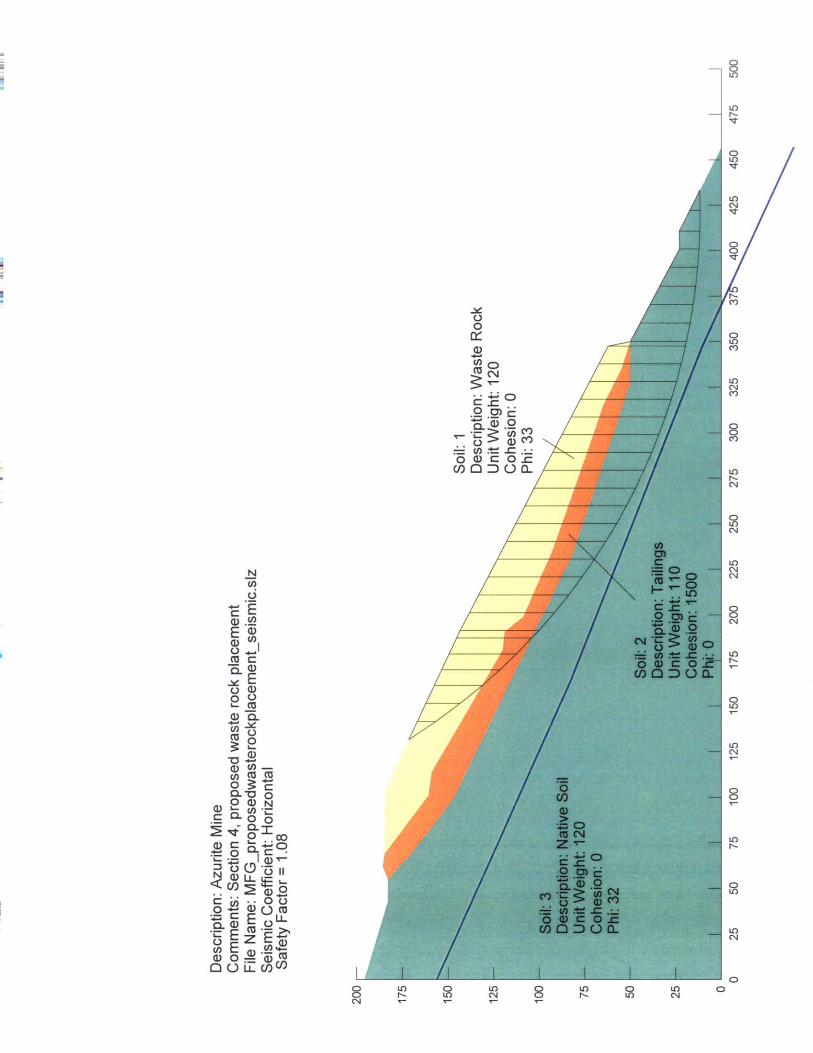


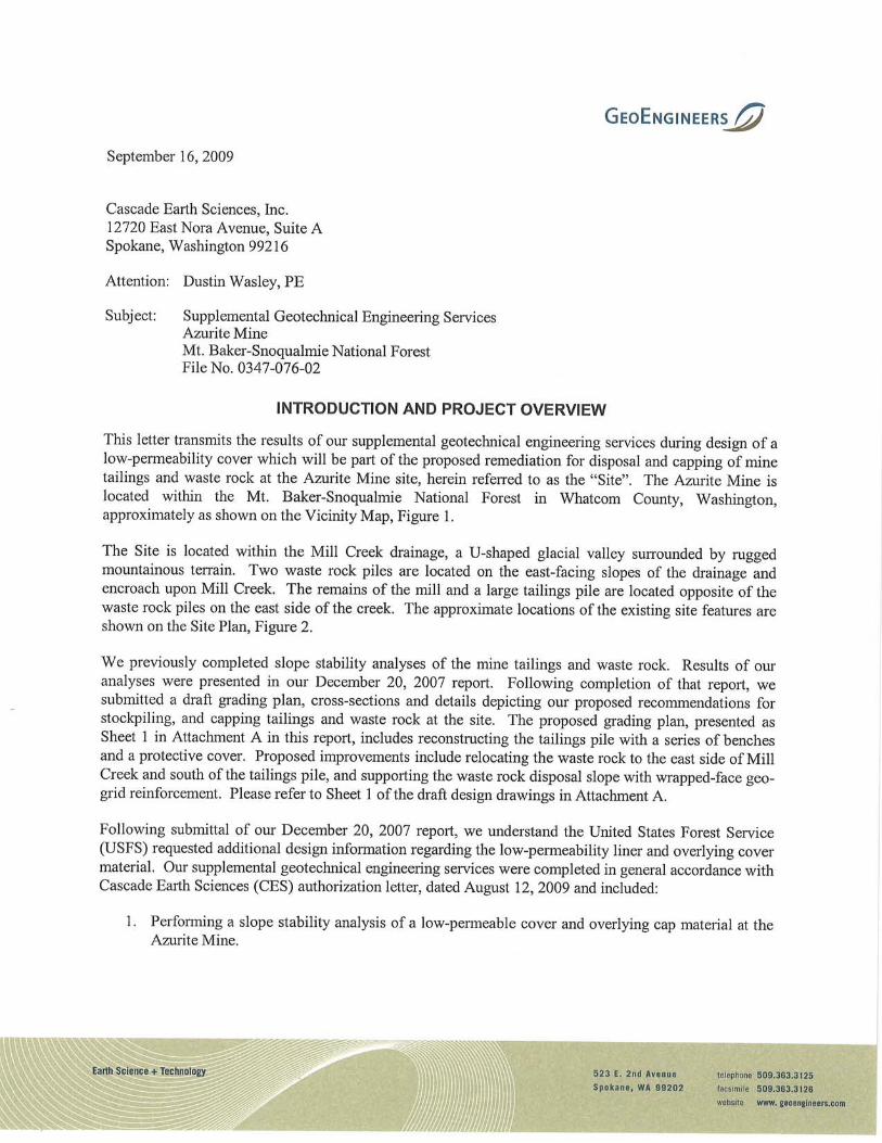

Cascade Earth Sciences, Inc. September 16, 2009 Page 2
File No. 0347-076-02
SOIL COVER STABILITY ANALYSES
GENERAL
In our referenced report, our recommendations included benching the slope and constructing a low-permeability cover over the tailings and waste rock. The regrading process will involve constructing approximate 8-foot-wide benches spaced at approximate 25- to 30-foot horizontal intervals along the slope. The low-permeability cover will include a geomembrane, protective geotextile layer and soil consisting of talus or topsoil. A typical detail for the tailings and waste rock benching and cover is presented as Sheet 5 of our draft design drawings in Attachment A.
There are three main design issues with respect to stability of a lined slope: stability of the subgrade soil; pullout of the cover consisting of geomembrane, geotextile and soil; and adequate tensile strength of the geomembrane and geotextile (geosynthetic) layers. A summary of our analysis and results for our evaluation of slope stability, pullout and tensile strength is provided below.
SLOPE STABILITY
The slope stability analysis involves evaluating the factor of safety against shear failure along a critical failure surface. The driving force is the applied stress along the failure surface that results from body and surcharge forces. The resistance is provided by the cohesive and frictional strength of the soil and other materials along the failure surface. A deep-seated slope stability analysis was one element of our December 2007 report and is not discussed as part of our current analysis, which focuses on near-surface failures below the soil component of the cover.
We used the computer program Slope/W to analyze the stability of the proposed benched slopes. We evaluated the stability of the soil layer directly overlying the geosynthetic layers on a slope inclined at 2.5H:1V (horizontal to vertical). We also evaluated the same scenario with an additional 100 pounds per square foot (psf) snow load overlying the soil layer. The results of our slope stability analyses for static conditions are presented in Table 1 with supporting output files presented in Attachment B.
Table 1. Results of Slope Stability Analyses (rounded to nearest 0.05)
Condition Factor of Safety
Soil Cover Only 1.85
Soil Cover Plus Snow Load 1.80
Ideally, acceptable stability factors typically are in the range of 1.4 to 1.5 for static conditions and diminish by roughly 0.1 to 0.3 for the seismic case. Because of the relatively high safety factors in Table 1, we did not complete a seismic stability analysis.
PULLOUT STABILITY
We evaluated the resistance of the geomembrane and geotextile against pullout. The pullout resistance on the geosynthetics is developed by the applied normal load of the soil layer above the geotextile that creates frictional resistance between the geomembrane and the underlying soil. We initially analyzed two possible pullout scenarios:
• Case 1 – Failure is caused by one or both layers of geosynthetics pulling out from the overlying soil component of the cover, or underlying tailings or waste rock.

Cascade Earth Sciences, Inc. September 16, 2009 Page 3
File No. 0347-076-02
• Case 2 – Failure is caused by one or both layers of geosynthetics moving down the slope along with the upper soil cover component.
Our analyses were completed based on the following assumptions:
• The friction angle between the geosynthetics is less than that between geosynthetics and overlying and underlying soil, and was used for design calculations.
• The geosynthetics extend along the full length of the slope bench and extend an additional 6 inches onto the upper slope, in accordance with the preliminary plans.
• A minimum of 2 feet of soil overlies the geosynthetics on the benched portions of the slope, in accordance with the preliminary plans.
On the basis of our initial analysis with an 8-foot-wide bench, we concluded that an inadequate safety factor (1.3) results for the Case 2 design condition. For this reason, we re-evaluated the pullout resistance using an approximate 2-foot-wide by 1-foot-deep anchor trench installed on each bench. We re-evaluated the resistance of the geosynthetics against pullout for the following three scenarios:
• Case 3 – Failure is caused by one or both layers of geosynthetics pulling out from the overlying soil component of the cover, or underlying tailings or waste rock.
• Case 4 – Failure includes mobilization of the passive soil wedge behind the anchor trench and causes one or both layers of the geosynthetic to slide along with the upper soil cover.
• Case 5 – Failure includes shearing of the soil behind the anchor trench and causes one or both layers of geosynthetics to slide along with the upper soil cover.
Soil and geosynthetic parameters and design calculations for Cases 1 through 5 are presented in Attachment C. The results of our pullout stability analyses are presented in Table 2.
Table 2. Results of Pullout Stability Analyses
Design Case Anchor Trench Factor of Safety
1 No 1.5
2 No 1.3
3 Yes 1.7
4 Yes 3.1
5 Yes 2.0
TENSILE STRENGTH
We also evaluated the required tensile strength of the geosynthetics by calculating the force that the soil cover and snow load imposes on the materials. Our analysis was completed based on the following assumptions:
• An approximate 1-foot-thick layer of talus will be placed directly on the geotextile layer, in accordance with the preliminary plans.
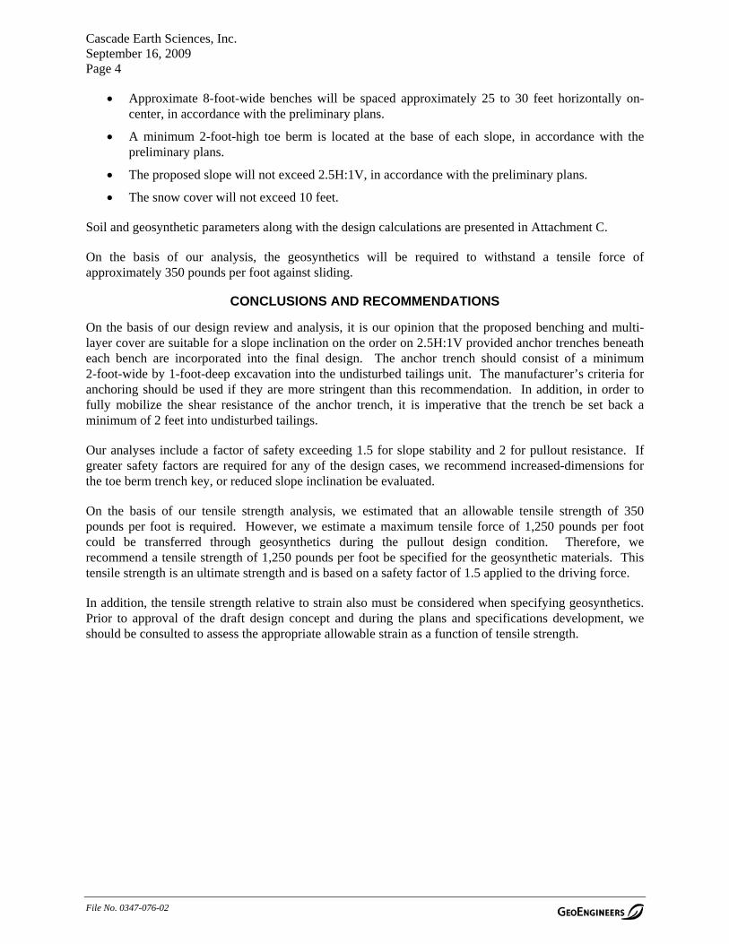
Cascade Earth Sciences, Inc. September 16, 2009 Page 4
File No. 0347-076-02
• Approximate 8-foot-wide benches will be spaced approximately 25 to 30 feet horizontally on-center, in accordance with the preliminary plans.
• A minimum 2-foot-high toe berm is located at the base of each slope, in accordance with the preliminary plans.
• The proposed slope will not exceed 2.5H:1V, in accordance with the preliminary plans.
• The snow cover will not exceed 10 feet.
Soil and geosynthetic parameters along with the design calculations are presented in Attachment C.
On the basis of our analysis, the geosynthetics will be required to withstand a tensile force of approximately 350 pounds per foot against sliding.
CONCLUSIONS AND RECOMMENDATIONS
On the basis of our design review and analysis, it is our opinion that the proposed benching and multi-layer cover are suitable for a slope inclination on the order on 2.5H:1V provided anchor trenches beneath each bench are incorporated into the final design. The anchor trench should consist of a minimum 2-foot-wide by 1-foot-deep excavation into the undisturbed tailings unit. The manufacturer’s criteria for anchoring should be used if they are more stringent than this recommendation. In addition, in order to fully mobilize the shear resistance of the anchor trench, it is imperative that the trench be set back a minimum of 2 feet into undisturbed tailings.
Our analyses include a factor of safety exceeding 1.5 for slope stability and 2 for pullout resistance. If greater safety factors are required for any of the design cases, we recommend increased-dimensions for the toe berm trench key, or reduced slope inclination be evaluated.
On the basis of our tensile strength analysis, we estimated that an allowable tensile strength of 350 pounds per foot is required. However, we estimate a maximum tensile force of 1,250 pounds per foot could be transferred through geosynthetics during the pullout design condition. Therefore, we recommend a tensile strength of 1,250 pounds per foot be specified for the geosynthetic materials. This tensile strength is an ultimate strength and is based on a safety factor of 1.5 applied to the driving force.
In addition, the tensile strength relative to strain also must be considered when specifying geosynthetics. Prior to approval of the draft design concept and during the plans and specifications development, we should be consulted to assess the appropriate allowable strain as a function of tensile strength.


Site
Whatcom County
Skagit County
Okanogan County
Brus h CreekBrush Creek
µSeatle
§̈¦54,000 4,0000
Feet
Data Sources: ESRI Data & Maps, Street Maps 2005
Notes:1. The locations of all features shown are approximate.2. This drawing is for information purposes. It is intended to assist in showing features discussed in an attached document. GeoEngineers, Inc. can not guarantee the accuracy and content of electronic files. The master file is stored by GeoEngineers, Inc. and will serve as the official record of this communication.3. It is unlawful to copy or reproduce all or any part thereof, whether for personal use or resale, without permission.
Transverse Mercator, Zone 10 N North, North American Datum 1983North arrow oriented to grid northO
ffic
e: S
PO
KP
ath:
P:\0
0\03
4707
6\02
\GIS
\MX
Ds\
0347
076
02F
igur
e1.m
xdM
ap
Rev
ise
d: D
ecem
ber
19
, 200
7
Vicinity Map
Figure 1
Azurite MineMt. Baker-Snoqualmie National Forest, Washington


ATTACHMENT A GRADING PLAN (SHEET 1) AND DETAILS (SHEET 5)
“DRAFT”

DRAFT

DRAFT

ATTACHMENT B SLOPE/W COMPUTER OUTPUT
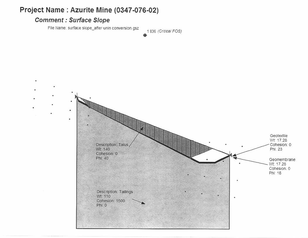
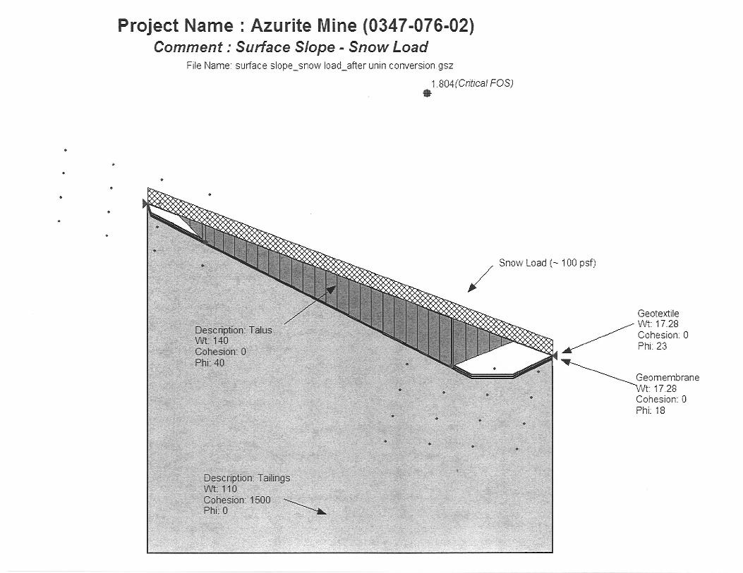
ATTACHMENT C HAND CALCULATIONS FOR PULLOUT AND TENSILE
RESISTANCE
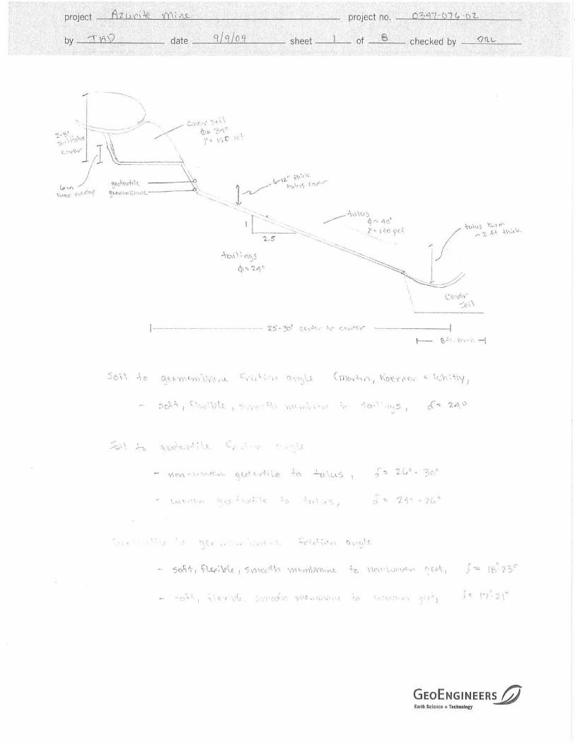


523 East Second Avenue Spokane, Washington 99202
509.363.3125
January 18, 2011
Cascade Earth Sciences 12720 East Nora Avenue, Suite A Spokane, Washington 99216
Attention: Dustin Wasley, PE
Subject: Geotechnical Engineering Services Azurite Mine Mt. Baker-Snoqualmie National Forest File No. 0347-076-02
INTRODUCTION
This letter transmits supplemental recommendations for site grading and geotextile specifications in support of the design of capping of mine tailings and waste rock at the Azurite Mine site, herein referred to as the “site”. This project was the subject of a previous letter report by GeoEngineers, the results of which are presented in our reports dated December 19, 2007, April 9, 2010, and preliminary plans.
We understand that since submittal of our report and preliminary plans, the project now will involve placing an approximate 5-foot-thick layer of waste rock (where existing site grades allow) across the existing tailings pile, and elimination of the planned reinforced slope to the south of the tailings pile as the main waste rock repository. The supplemental recommendations contained in this letter are based on completion of stability evaluations of the liner/cap veneer stability, and assumed interface friction properties of the liner fabrics, cover soil and subgrade.
RECOMMENADITONS
We recommend the following parameters be used in designing grading plans for the tailings pile/waste rock repository.
■ Maximum slope inclinations of 2.5H:1V (horizontal to vertical) should be utilized for most of the site. A maximum slope inclination of 2H:1V may be used within the northeast portion of the tailings pile where current slopes are inclined steeper than 2H:1V. The intent of this recommendation is to reduce the amount of earthwork and cutting into the currently stable tailings pile. In our opinion, maintaining a steeper slope inclination over a relatively short slope length will be more practical than completing significant earthwork within the tailings pile. However, we recommend that some additional explorations be completed within the upper (steep) portion of the tailings pile before earthwork is completed in order to assess the condition of the tailings.

Cascade Earth Sciences, Inc. | January 18, 2011 Page 2
File No. 0347-076-02
■ For 2.5H:1V slopes, we recommend constructing benches along the slopes at approximate 30 foot intervals (i.e. a 30-foot slope length measured from the back of one bench to the face of the next bench). For 2H:1V slopes, we recommend constructing benches along the slope at approximate 20 foot intervals. The benches should be about 8 feet wide. The purpose of the benches will be to assist the contractor in placing cover soil, and to provide buttresses of cover soil (talus) along the slope face to provide anchorage trenches for geotextile, geomembrane and geogrid. These buttresses and anchorage trenches will provide stability for the cap (cover soil, geogrid, getoextiles and geomembrane.
■ We recommend that soil intended as cover material over the tailings pile be placed in maximum 12-inch thick loose lifts and compacted to at least 90 percent of maximum dry density based on the ASTM International (ASTM D 1557) laboratory test procedure. The actual lift thickness may be adjusted in the field based on compaction test results, and requirements to protect underlying geotextiles. Cover soil (talus) placed above the line should not be compacted.
■ We recommend that a three or four layer system of geosynthetics be utilized for the cap. This includes: a lower geotextile fabric to provide a cushion between the sugrade soil (tailings and waste rock) and the geomembrane; a low-permeability geomembrane; an upper layer of geotextile fabric to provide a cushion between the geomembrane and the cover soil (talus); and a layer of uniaxial geogrid to provide tensile strength to support the cover soil. The geogrid layer may be omitted if the upper geotextile fabric meets the specifications provided herein for geogrid.
■ We recommend that the geotextile fabric meet the specifications presented in Table 1:
TABLE 1 RECOMMENDED GEOTEXTILE FABRIC SPECIFICATIONS
Property Unit Minimum Average Roll Value (MARV)
Grab Tensile Strength (ASTM D 4632) Lbs 300
Trapezoidal Tear Strength (ASTM D 4533) Lbs. 115
Puncture Resistance (ASTM D 6241) Lbs. 800
Apparent Opening Size (AOS) U.S. Sieve U.S. No. 30 max
Permittivity (ASTM D 4491) Sec-1 0.02 min
UV Resistance (ASTM D 4355) % Strength Retained 70%
For reference, Mirafi 1120N 12 oz. non-woven fabric meets these specifications.
■ We recommend that geogrid meet the specifications presented in Table 2:
TABLE 2 RECOMMENDED GEOGRID FABRIC SPECIFICATIONS
Property Unit Minimum Average Roll Value (MARV)*
Long-Term Design Strength (LTDS) (GRI GG4-MD) (lb/ft) 3,100
* Based on a creep reduction factor (RFCR) for 10% strain, and installation damage reduction factor (RFID) for crushed gravel)
For reference, Tensar UX1600, Synteen SF65 and Miragrid 7XT meet these specifications.


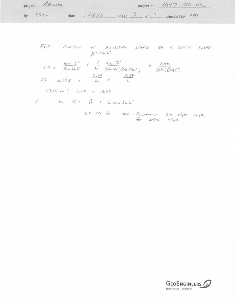
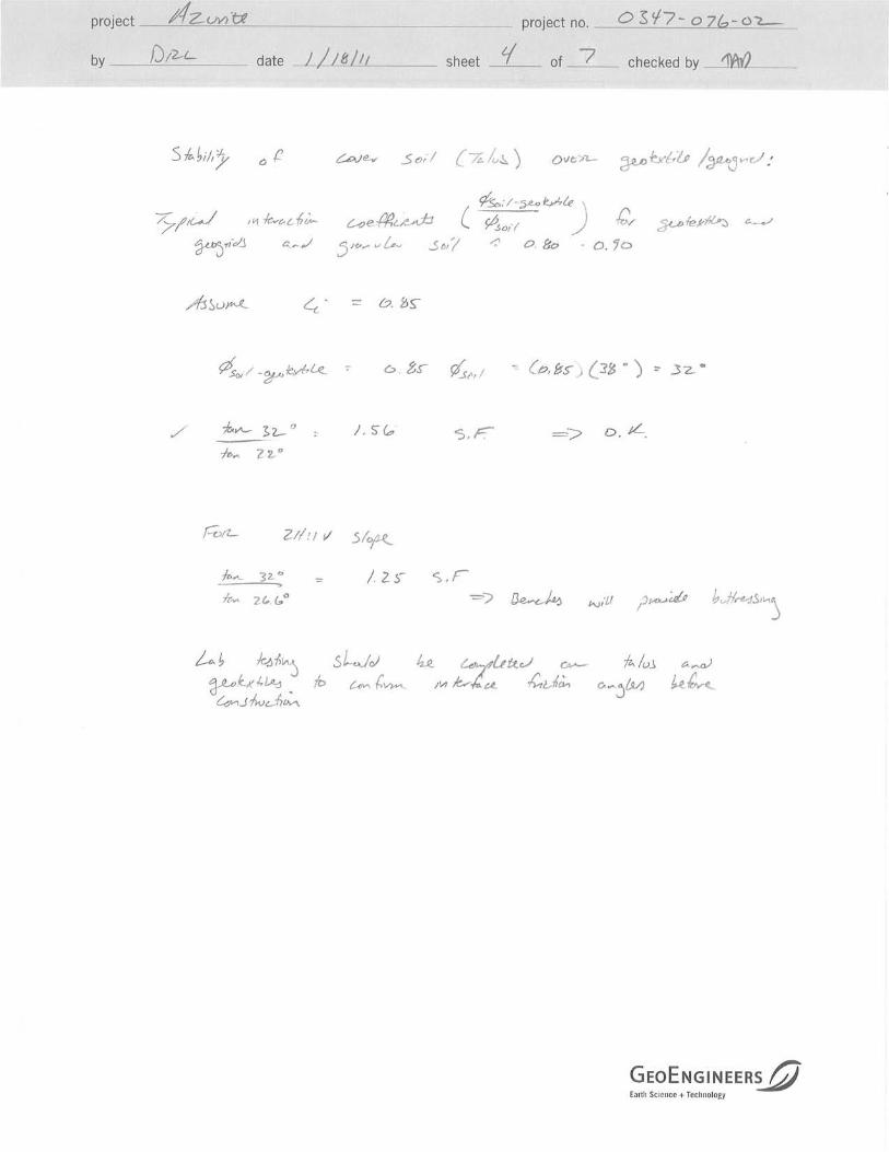
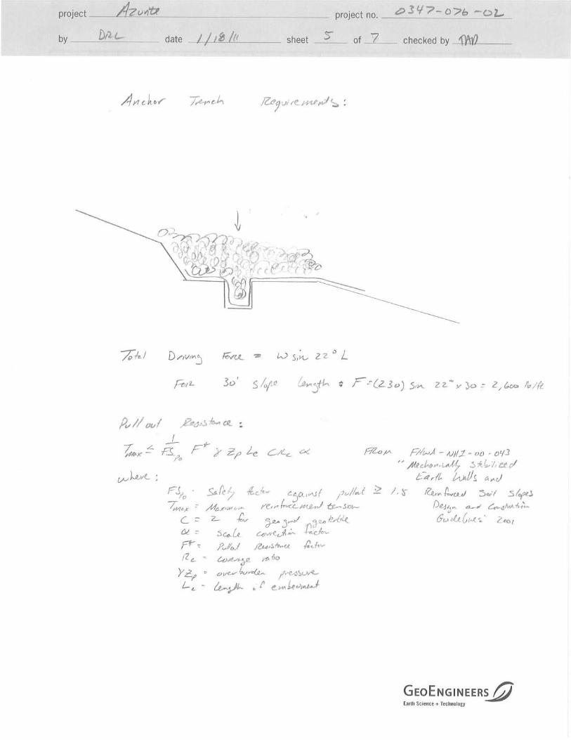


Appendix D.
Laboratory Analyses

Table 1. Surface Water Analytical ResultsAzurite Mine Removal ActionMt. Baker-Snoqualmie National Forest - Whatcom County, Washington
Results in µg/L
Tinson Adit Seep
AM-AS-01 8/27/2004 CES 40 B < 0.2 0.52 19.3 19.8 < 3 < 2 0.1 B 22,100 < 10 < 10 0.9 B 80 0.1 B #### < 5 < 0.2 0.00125 < 10 < 300 < 1 < 0.05 900 B < 0.1 < 5 < 10
TTDIS 9/8/2005 MFG NA NA NA NA 26.4 NA NA 0.19 NA < 1.25 NA 2.97 NA < 0.5 NA 5.74 < 0.2 NA NA NA NA NA NA NA NA 16.4
AM-AS-01 6/24/2010 CES 90.9 NA NA NA 29.2 0.92 NA 0.17 19,100 0.28 J NA 3.6 504 0.066 J NA NA NA NA 1 157 B NA NA 651 NA NA 53.1
AM-AS-01 9/22/2010 CES 41.6 B 24.8 1.3 0.092 < 0.24 2 145 0.033 J 0.66 11.5
Wenatchee Waste Seep
AM-SP-01 8/28/2004 CES 720 < 0.2 0.25 2.75 3 < 3 < 2 0.7 17,300 < 10 20 B 81.2 430 1 #### 153 < 0.2 0.000774 10 B 1,100 < 1 < 0.05 2,100 0.07 B < 5 40
Seep-2 9/8/2005 MFG NA NA NA NA 5.27 NA NA 0.2 NA 1.48 NA 6.78 NA 0.74 NA 15.4 < 0.2 NA NA NA NA NA NA NA NA 29.3
AM-SP-01 6/24/2010 CES 284 NA NA NA 2.5 2.8 NA 0.28 20,000 < 0.24 NA 4.9 14.2 J 0.056 J NA NA NA NA 3.8 616 B NA NA 1,260 NA NA 41.9
AM-SP-01 9/22/2010 CES 121 B 2.4 3.1 0.12 < 0.24 3.4 16.2 J 0.11 1.7 13.1
Tailings Seep
AM-SP-02 8/28/2004 CES 90 B < 0.2 NA NC 1.8 B < 3 < 2 0.1 B 11,900 < 10 < 10 1.7 B < 10 0.2 B #### 10 B < 0.2 NA < 10 600 B < 1 < 0.05 1,200 0.05 B < 5 < 10
Seep-1 9/8/2005 MFG NA NA NA NA 12.6 NA NA 4.61 NA 9.7 NA 1,180 NA 6.34 NA 688 < 0.2 NA NA NA NA NA NA NA NA 542
AM-SP-02 6/24/2010 CES 24,800 NA NA NA 0.45 J 14.3 NA 2.9 NA 1.5 NA 592 251 2.3 NA NA NA NA 43.9 3,200 B NA NA 4,590 NA NA 410
AM-SP-02 9/22/2010 CES 12,300 B 1.4 12.7 2.6 1.3 206 660 1.3 23 330
Canyon Creek
CC-SW-01 8/26/2004 CES < 30 0.2 B 0.14 1.46 1.6 B 9 B < 2 < 0.1 20200 < 10 < 10 < 0.5 20 B 0.1 B 3500 < 5 < 0.2 0.000385 < 10 < 300 < 1 < 0.05 2000 0.05 B < 5 < 10
CC-SW-01 6/23/2010 CES 185 NA NA NA 1.3 6.5 NA < 0.02 NA 0.32 J NA 0.6 200 0.085 J NA NA NA NA 0.25 J NA NA NA NA NA NA 15.8
CC-SW-01 9/20/2010 CES 36.8 B 1.5 8.4 < 0.02 0.46 J 0.34 J 80.9 < 0.02 < 0.19 4.5 J
CC-SW-02 8/26/2004 CES < 30 0.2 B 0.11 1.59 1.7 B 6 B < 2 < 0.1 17600 < 10 < 10 0.6 B 10 B 0.1 B 2800 < 5 < 0.2 0.000422 < 10 < 600 < 1 < 0.05 1600 0.06 B < 10 < 10
CC-SW-02 6/23/2010 CES 382 NA NA NA 2.1 4.3 NA 0.021 J NA 1 NA 2.5 458 0.32 NA NA NA NA 0.6 NA NA NA NA NA NA 11.4
CC-SW-02 9/20/2010 CES 36.2 B 1.5 5.9 < 0.02 0.29 J 0.42 J 39.8 J < 0.02 < 0.19 4.1 J
Mill Creek
MC-SW-01a 6/24/2010 CES 213 NA NA NA 1.4 2.7 NA < 0.02 NA 0.55 NA 1.1 337 0.15 NA NA NA NA 0.45 J NA NA NA NA NA NA 10.9
MC-SW-01a 9/22/2010 CES 6.7 B 0.6 1.7 < 0.02 < 0.24 < 0.2 < 4.5 < 0.02 < 0.19 2.4 J
MC-SW-01b 6/24/2010 CES 425 NA NA NA 1.6 3.9 NA < 0.02 NA 1.2 NA 2.4 695 0.19 NA NA NA NA 0.84 NA NA NA NA NA NA 11.6
MC-SW-01b 9/22/2010 CES 21.4 B 0.55 2 < 0.02 < 0.24 < 0.2 28 J < 0.02 < 0.19 2.1 J
MC-SW-01 8/27/2004 CES 90 B < 0.2 0.04 NC < 0.5 < 3 < 2 < 0.1 4,700 < 10 < 10 < 0.5 20 B 0.1 B 400 B < 5 < 0.2 0.000174 B < 10 400 B < 1 < 0.05 800 B 0.07 B < 5 < 10
MC-SW-02 8/27/2004 CES 30 B < 0.2 0.04 0.46 0.5 B < 3 < 2 < 0.1 4,900 < 10 < 10 < 0.5 30 B 0.1 B 500 < 5 < 0.2 0.000104 B < 10 400 B < 1 < 0.05 900 B < 0.05 < 5 < 10
MC-SW-02a 6/24/2010 CES 498 NA NA NA 1.5 4.4 NA < 0.02 NA 1.4 NA 3 783 0.21 NA NA NA NA 1 NA NA NA NA NA NA 34.4
MC-SW-02a 9/21/2010 CES 56.1 B 0.67 2.3 < 0.02 < 0.24 1.1 70.5 < 0.02 0.39 J 3 J
MC-SW-02b 6/24/2010 CES 681 NA NA NA 2.2 5.2 NA 0.038 J NA 1.8 NA 3.8 1110 0.28 NA NA NA NA 1.3 NA NA NA NA NA NA 13.2
MC-SW-02b 9/21/2010 CES 71.5 B 0.89 2.7 0.045 J 0.26 J 1.2 102 0.043 J 0.44 J 3.6 J
SW-1 9/8/2005 MFG NA NA NA NC 0.853 NA NA < 0.12 NA < 1.25 NA NA NA < 0.5 NA 0.46 < 0.2 NA NA NA NA NA NA NA NA < 2
209.27 < 0.1 0.04 0.46 1.024 3.2 < 1 0.02377 4800 2.225 < 5 1.8 318 0.183 450 1.82 < 0.1 0.000139 2.265 400 < 0.5 < 0.03 850 0.03 < 2.5 11.59
MC-SW-03 8/25/2004 CES 40 B < 0.2 0.05 1.15 1.2 B < 3 < 2 < 0.1 5600 < 10 < 10 1.1 B 60 0.3 B 500 B < 5 < 0.2 0.000316 < 10 400 B < 1 < 0.05 700 B < 0.05 < 5 < 10
MC-SW-03 6/24/2010 CES 724 NA NA NA 2.9 5 NA 0.04 J NA 2.1 NA 3.9 1140 0.41 NA NA NA NA 1.3 NA NA NA NA NA NA 20.8
MC-SW-03 9/21/2010 CES 61.2 1.2 2.4 0.042 J < 0.24 0.99 81.4 0.035 J 0.34 J 4.1 J
MC-SW-04 8/25/2004 CES 60 B < 0.2 0.6 0.7 1.3 B < 3 < 2 < 0.1 5900 < 10 < 10 2.6 B 80 0.2 B 500 B 6 B < 0.2 0.000279 < 10 500 B < 1 < 0.05 700 B 0.09 B < 5 < 10
MC-SW-04 6/24/2010 CES 702 NA NA NA 2.5 5.4 NA 0.048 J NA 2 NA 5 1100 0.44 NA NA NA NA 1.6 NA NA NA NA NA NA 33.1
MC-SW-04 9/21/2010 CES 55.7 B 1.1 2.4 0.054 J < 0.24 1.2 60.6 < 0.02 0.36 J 3.2 J
SW-2 9/8/2005 MFG NA NA NA NC 1.31 NA NA < 0.12 NA < 1.25 NA NA NA < 0.5 NA 0.29 < 0.2 NA NA NA NA NA NA NA NA 2.3
MC-SW-05 8/28/2004 CES < 30 < 0.2 0.11 1.49 1.6 B < 3 < 2 < 0.1 7700 < 10 < 10 0.9 B 10 B 0.1 B 700 B < 5 < 0.2 NA < 10 500 B < 1 < 0.05 800 B 0.07 B < 5 < 10
MC-SW-05 6/24/2010 CES 784 NA NA NA 3.3 5 NA 0.041 J NA 2.1 NA 5.2 1160 0.48 NA NA NA NA 1.4 NA NA NA NA NA NA 9.3
MC-SW-05 9/21/2010 CES 37.5 B 1.6 2.6 0.033 J 0.26 J 1.4 38 J < 0.02 0.21 J 1.8 J
SW-3 9/8/2005 MFG NA NA NA NC 2.12 NA NA < 0.12 NA < 1.25 NA NA NA 0.72 NA 7.36 < 0.2 NA NA NA NA NA NA NA NA 8.57
MC-SW-06 8/26/2004 CES < 200 < 0.2 0.15 1.75 1.9 B < 20 < 10 < 0.1 12000 < 50 < 50 0.7 B < 50 0.6 1000 B < 30 < 0.2 0.000234 B < 50 < 2000 < 1 < 0.05 < 2000 0.07 B < 30 < 50
MC-SW-06 6/23/2010 CES 398 NA NA NA 2 3.1 NA 0.035 J NA 1.1 NA 2.7 499 0.36 NA NA NA NA 0.68 NA NA NA NA NA NA 13.5
MC-SW-06 9/20/2010 CES 58.3 B 1.9 2.9 0.025 J 0.43 J 1.1 69.8 0.052 J 0.21 J 2.4 J
Standards, corrected for hardness where applicable (used 24 mg/L average for surface water samples, excluding portal and other seeps)
NS NS NS NS 190 NS NS 0.37 NS NS NS 3.5 NS 0.52 NS NS 0.012 0.012 76.4 NS 5 NS NS NS NS 31.72
NS 14 NS NS 0.018 NS NS NS NS NS NS NS NS NS NS NS 0.14 0.14 610 NS 170 NS NS 1.7 NS NS
NS 6 NS NS 10 #### 4 5 NS 100 NS NS 300 NS NS 50 2 2 100 NS 50 100 NS 2 NS 50,000
87 NS NS NS 150 NS NS 0.091 NS NS NS 2.7 1,000 0.52 NS NS 0.77 0.77 15.59 NS 5 NS NS NS NS 35.36
NS 5.6 NS NS 0.018 #### NS NS NS NS NS 1,300 300 NS NS 50 NS NS 610 NS 170 NS NS 1.7 NS 7,400
87 30 190 3.1 NS 4 0.66 1.10 NS NS 23 12 1,000 3.20 NS 120 1.3 1.3 160 NS 0.39 0.36 NS 9 20 110
Nic
kel
, TR
Pot
assi
um
, TR
Mer
cury
, Tot
al,
Tra
ce
Mer
cury
, Tot
al
Mag
nes
ium
, TR
Zin
c, T
R
Th
alli
um
, TR
Van
adiu
m, T
R
Sod
ium
, TR
Sel
eniu
m, T
R
Sil
ver,
TR
Cal
ciu
m, T
R
Washington - Aquatic Life (Chronic) 1
Washington - Human Health 2
Washington Drinking Water Criteria 3
EPA - Aquatic Life (CCC) 4
Sample I.D.
Alu
min
um
, TR
Iron
, TR
*
Ch
rom
ium
, TR
Cop
per
, TR
Cob
alt,
TR
Sam
pli
ng
En
tity
(C
ES
, MF
G)
EPA - Human Health (Water+Organism) 5
ORNL - Surface Water PRGs 6
Sam
ple
Dat
e
Average
Man
gan
ese,
TR
*
Cad
miu
m, T
R
An
tim
ony,
TR
Ber
ylli
um
, TR
Bar
ium
, TR
Ars
enic
(II
I), T
R
Ars
enic
Tot
al, T
R
Ars
enic
(V
), T
RC
alcu
late
d
Lea
d, T
R
Cascade Earth Sciences - Spokane, WADoc: 2010230015 Azurite Tables.xlsx (T1 SW)
Page 1 of 2 Azurite Mine4/27/2011

Table 1. Surface Water Analytical ResultsAzurite Mine Removal ActionMt. Baker-Snoqualmie National Forest - Whatcom County, Washington
s.u. mS/cm mg/L
Tinson Adit Seep GENERAL NOTES:
AM-AS-01 8/27/2004 CES 0.04 7.2 7.65 7.3 0 140 107 12.5 184 63 90 70 6 B 10 B NA NA All CES 2004 analyses except Arsenic (III), TR & Mercury, Total, Trace were conducted by ACZ Laboratories, Inc. in Steamboat Springs, Colorado per
TTDIS 9/8/2005 MFG 0.0013 NM NM NA NM NM NM NM NA NM NA 14 NA NA NA EPA Method 200.7/200.8.
AM-AS-01 6/24/2010 CES 0.008 5.43 6.02 7.4 H NM 64 NM 9.28 56.7 53.5 NM 62 < 2 11 0.1 J 41.8 All MFG 2005 analyses were completed by SVL Analytical in Kellogg, Idaho per EPA Method 200.7/200.8.
AM-AS-01 9/22/2010 CES 0.009 4.38 7.46 7.4 H NM 74 117 11.72 -171 55.8 NM 75 11 11.3 0.11 J 51.3 All CES 2010 analyses were conducted by Pace Analytical Services, Inc. in Seattle, Washington per EPA Method 6010/6020.
Wenatchee Waste Seep Arsenic (III), TR and Mercury, Total, Trace analyses were conducted by Brooks Rand in Seattle, Washington.
AM-SP-01 8/28/2004 CES NM 4.8 4.33 5.5 10 200 172 13 354 70 130 120 < 5 80 NA NM Arsenic (V) was calculated from difference between Arsenic, TR and Arsenic (III), TR.
Seep-2 9/8/2005 MFG 0.0006 NM NM NA NM NM NA NM NM NA NM NA < 5 NA NA NA Surface water metals concentrations in samples collected by MFG from Mill Creek are presented as the mean concentration of three replicates.
AM-SP-01 6/24/2010 CES 0.007 3.94 6.17 7 H NM 77 NA 9.59 28.2 60.4 NM 83 < 2 35.2 6.2 20 Abbreviations: < value = analyte not detected above Method Detection Limit (MDL), B = analyte detected between MDL and Practical Quantification Limit (PQL),
AM-SP-01 9/22/2010 CES 0.002 5.13 6.97 4.2 H NM 72 108 10.81 -138 47.5 NM 72 < 2 27.7 0.13 J 26.8 H = hold time exceeded, J = estimated concentration above the adjusted MDL and below the adjusted reporting limit, µg/L = micrograms per liter,
Tailings Seep mg/L = milligrams per liter, mS = microSiemans, NA = not analyzed, NC = not calculated, NM = not measured, s.u. = standard units.
AM-SP-02 8/28/2004 CES NM 6.8 6.53 6.5 0 90 76 12.6 215 36 60 60 < 5 20 B NM NM Bold identifies the average background concentration from the CES (2004) SI; MFG (2005); and CES (2010) RA DGI field investigations.
Seep-1 9/8/2005 MFG NM NM NM NA NM NM NA NM NM NA NM NA 262 NA NA NA Italic values indicate that the MDL exceeds the lowest standard.
AM-SP-02 6/24/2010 CES 0.0002 8.83 5.51 3.9 H NM 437 NM 8.06 128 16.8 NM 21 3 337 0.22 J < 2 Shaded cells indicate that the value exceeds one or more standard; corresponding criteria also shaded.
AM-SP-02 9/22/2010 CES NM 5.94 6.97 6.6 H NM 228 371 9.43 -120 11.6 NM 293 47 186 0.2 J < 2
Canyon Creek
CC-SW-01 8/26/2004 CES 85.5 10.9 7.63 7.7 0 140 119 12.3 179 65 90 90 6 B 10 B NA NA STANDARD NOTES:
CC-SW-01 6/23/2010 CES NM 6.44 NM 7.6 H NM 45 NA 9.53 110.2 33 NM 44 < 2 NA NA NA 1 - State of Washington Aquatic Life criteria (WAC 173-201A), underline - corrected for hardness, italics - expressed as Dissolved
CC-SW-01 9/20/2010 CES 78.7 8.95 7.46 8 H NM 90 127 11.87 -26.4 61 NM 73 H 3 H 2 - State of Washington criteria for protection of human health (CLARC-Part IIIf)
CC-SW-02 8/26/2004 CES 111 10.6 7.24 7.2 H 26 130 103 12.4 191 56 80 70 < 5 < 10 NA NA 3 - State of Washington drinking water criteria (WAC 246-290)
CC-SW-02 6/23/2010 CES NM 7.67 NM 7.4 NM 27 NM 9.62 125.7 28.3 NM 33 8 NA NA NA 4 - EPA recommended chronic ambient water quality criteria for freshwater aquatic life used (EPA, 2002), underline - corrected for hardness,
CC-SW-02 9/20/2010 CES 77.9 9 7.53 7.9 H NM 76 104 11.78 -25.6 49.7 NM 68 H 2 H italics - expressed as Dissolved
Mill Creek 5 - EPA recommended ambient water quality criteria for protection of human consumption of water and fish (EPA, 2002 NTR),
MC-SW-01a 6/24/2010 CES 16.4 3.28 NM 6.8 H NM 14 NM 10.35 105.6 10 NM 18 6 NA NA NA italics - expressed as Dissolved
MC-SW-01a 9/22/2010 CES 1.4 5.47 6.84 7.1 H NM 19 28.8 11.91 -121 11.8 NM 26 < 2 6 - ORNL Preliminary Remediation Goals for Ecological Endpoints (ORNL, 1997)
MC-SW-01b 6/24/2010 CES 40.6 3.7 NM 5.6 H NM 15 NM 10.33 148.8 10.9 NM 29 14 NA NA NA NS = No Standard
MC-SW-01b 9/22/2010 CES 1.8 5.66 6.97 7.3 H NM 24 36 13 -175 15.1 NM 27 2
MC-SW-01 8/27/2004 CES 12.6 6 7.08 7.1 1 40 31 12.1 138 13 30 20 < 5 < 10 NA NA
MC-SW-02 8/27/2004 CES 6.71 6.1 7.03 7.1 1 40 33 12.2 149 14 30 20 6 B 10 B NA NA
MC-SW-02a 6/24/2010 CES 40.3 3.73 NM 7.2 H NM 15 NM 10.42 127.9 11.9 NM 22 16 NA NA NA
MC-SW-02a 9/21/2010 CES 2.8 6.24 7.02 7.3 H NM 23 36 12.15 -53.4 13.7 NM 24 H 4 H
MC-SW-02b 6/24/2010 CES 41.4 3.45 NM 7.1 H NM 16 NM 10.37 128.4 NA NM 19 17 NA NA NA
MC-SW-02b 9/21/2010 CES 11.3 6.53 6.92 7.4 H NM 24 36.7 11.92 -51.4 13.9 NM 24 H 27 H
SW-1 9/8/2005 MFG 0.6 NM NM NA NM NM NM NM NM NA NM NA < 5 NA NA NA
15.992 5.02 6.98 7 1 23 33.583 11.475 39.69 12.7 30 22.9 9.455 10
MC-SW-03 8/25/2004 CES 5.05 6.4 6.61 7.3 0 50 34 12.7 201 16 30 30 < 5 < 10 NA NA
MC-SW-03 6/24/2010 CES 64.7 4.15 NM 6.9 H NM 14 NM 9.92 140.3 13.3 NM 17 35 NA NA NA
MC-SW-03 9/21/2010 CES 7.6 6.19 7.08 7.5 H NM 26 39.7 12.16 -74.6 16.4 NM < 5 H 3 H
MC-SW-04 8/25/2004 CES 8.26 6.5 6.34 7.2 3 50 37 12.7 211 17 30 40 < 5 < 10 NA NA
MC-SW-04 6/24/2010 CES 90.9 4.02 NM 6.6 H NM 16 NM 10.35 71.2 16.8 NM 26 12 NA NA NA
MC-SW-04 9/21/2010 CES 7 5.36 7.8 7.6 H NM 29 43.3 12.51 -7.2 17.3 NM 30 H 3 H
SW-2 9/8/2005 MFG NM NM NM NA NM NM NM NM NM NA NM NA < 5 NM NA NA
MC-SW-05 8/28/2004 CES 18.8 7.4 7.28 7.1 0 60 49 12.7 164 22 40 30 < 5 < 10 NA NA
MC-SW-05 6/24/2010 CES 123.6 4.35 NM 7.5 H NM 24 NM 9.28 56.4 17 NM 17 16 NA NA NA
MC-SW-05 9/21/2010 CES 13.7 5.68 7.78 7.6 H NM 37 58.1 12.31 -71 25 NM 36 H 2 H
SW-3 9/8/2005 MFG 3.1 NM NM NA NM NM NM NM NM NA NM NA 8 NA NA NA
MC-SW-06 8/26/2004 CES 22 10.5 7.08 7.4 12 80 63 12.4 217 34 50 50 < 5 < 10 NA NA
MC-SW-06 6/23/2010 CES 179.2 8.29 NM 7.5 H NM 32 NM 9.39 104.9 24 NM 31 4 NA NA NA
MC-SW-06 9/20/2010 CES 18.1 9.09 7.45 7.9 H NM 55 74.8 11.94 -34 35.5 NM 51 H 3 H
NS 12 6.5-8.5 6.5-8.5 5>Bkg NS NS 9.5 NS NS NS NS NS NS NS NS
NS NS NS NS NS NS NS NS NS NS NS NS NS NS NS NS
NS NS 6.5-8.5 6.5-8.5 NS 700 700 NS NS NS 500 500 NS 250 250 NS
NS 9-19 6.5-9 6.5-9 NS NS NS 9.5 NS NS NS NS NS NS NS NS
NS NS 5-9 5-9 NS NS NS NS NS NS NS NS NS NS NS NS
NS NS NS NS NS NS NS NS NS NS NS NS NS NS NS NS
Alk
alin
ity
(Tot
al a
s C
aCO
3)
ORNL - Surface Water PRGs 6
Washington - Aquatic Life 1
Washington - Human Health 2
Washington Drinking Water Criteria 3
EPA - Aquatic Life 4
EPA - Human Health (Water+Organism) 5
Oxy
gen
R
edu
ctio
n
Pot
enti
al
(Fie
ld)
NTU
Ch
lori
de
pH
(F
ield
)
Tem
per
atu
re
(Fie
ld)
Su
lfat
e
mg/L
TS
S, R
esid
ue,
N
on-F
ilte
rab
le
@10
5C
Con
du
ctiv
ity
@25
C (
Lab
)
mV
Har
dn
ess
as
CaC
O3,
TR
TD
S (
Fie
ld)
Dis
solv
ed
Oxy
gen
(F
ield
)
Sam
pli
ng
En
tity
(C
ES
, MF
G)
Sam
ple
Dat
e
pH
(L
ab)
Tu
rbid
ity
(Fie
ld)
cfs
Flo
w R
ate
Con
du
ctiv
ity
(Fie
ld)
oC
Average
Sample I.D.
Standards
TD
S, R
esid
ue,
F
ilte
rab
le
@18
0C
Cascade Earth Sciences - Spokane, WADoc: 2010230015 Azurite Tables.xlsx (T1 SW)
Page 2 of 2 Azurite Mine4/27/2011

Table 2. Sediment Analytical ResultsAzurite Mine Removal ActionMt. Baker-Snoqualmie National Forest - Whatcom County, Washington
mg/kg
Canyon Creek
CC-SS-01 8/26/2004 CES 21,900 0.3 B 31.3 97.2 0.4 B 0.4 5230 52 17 43.3 41,400 11.4 12,600 686 < 0.04 41.5 2,410 < 0.5 0.31 450 0.9 B 76.2 99
CC-SS-01 6/23/2010 CES 25,700 NA 37.1 32.3 NA < 0.051 NA 77.5 NA 99.7 42,300 6.7 NA NA NA 52.1 NA NA NA NA NA NA 96.5
CC-SS-01 9/20/2010 CES 16,900 31.5 49.9 < 0.051 43.2 92.4 43,800 9.5 47.7 162
CC-SS-02 8/26/2004 CES 28,300 0.3 B 28.6 71.2 0.3 B 0.74 7560 99 23 64.7 42,400 8.27 19,200 683 < 0.04 47.7 2,480 < 0.5 0.5 990 0.15 B 116 101
CC-SS-02 6/23/2010 CES 26,500 NA 42 NA NA < 0.054 NA 72.8 NA 109 45,200 8.4 NA NA NA 49 NA NA NA NA NA NA 130
CC-SS-02 9/20/2010 CES 21,000 21 29.5 < 0.052 73.7 86.3 43,700 7.9 52 159
Mill Creek
MC-SS-01a 6/24/2010 CES 9,150 NA 80.1 29.8 NA < 0.057 NA 25.4 NA 81.5 42,900 6.5 NA NA NA 29.4 NA NA NA NA NA NA 81.9
MC-SS-01a 9/22/2010 CES 9,870 28.1 26 < 0.11 19.2 79.4 52,800 0.7 39 J 15.8
MC-SS-01b 6/24/2010 CES 13,900 NA 37.7 44 NA < 0.06 NA 44.6 NA 117 47,000 5.6 NA NA NA 30.1 NA NA NA NA NA NA 75.1
MC-SS-01b 9/22/2010 CES 17,400 50.6 37.5 < 0.061 116 114 56,200 4.9 56.9 58.2
MC-SS-01 8/27/2004 CES 13,900 0.3 B 19.6 46.9 0.4 B 0.38 1980 40 11 59.1 34,200 4.72 7,240 615 < 0.05 20.2 2,150 0.5 0.23 290 0.18 B 65.3 62
MC-SS-02 8/27/2004 CES 15,800 0.4 B 20.5 57.4 0.4 B 0.51 2930 40 12 50.4 34,800 4.7 8,000 636 < 0.04 20.3 2,360 0.5 0.26 420 0.19 B 71.1 66
MC-SS-02a 6/24/2010 CES 10,800 NA 22.9 36.7 NA < 0.056 NA 25.3 NA 59 32,400 6.1 NA NA NA 20.1 J NA NA NA NA NA NA 86.6
MC-SS-02a 9/21/2010 CES 11,500 18.6 32 < 0.042 17.4 58.7 34,200 0.57 27.3 1.7 J
MC-SS-02b 6/24/2010 CES 12,000 NA 133 36.7 NA < 0.054 NA 19.3 NA 74.8 39,900 4.2 NA NA NA 23.6 NA NA NA NA NA NA 111
MC-SS-02b 9/21/2010 CES 10,600 22.6 28.2 < 0.048 24.9 64.6 37,700 3 29.7 55.9
SW-1 9/8/2005 MFG NA NA 23.2 NA NA 2.66 NA 38.77 NA 93.83 NA 5.37 NA NA < 0.033 22.83 NA NA NA NA NA NA 113.2
16,576 0.33 38.1 43.7 0.38 0.3168 4425 48.7688 15.8 79.278 41,931 5.796 11,760 655 0.041 35.85 2,350 0.5 0.33 538 0.36 82.2 86.8
MC-SS-03 8/25/2004 CES 23,900 0.4 B 59.1 59.2 0.3 B 1.7 5030 81 20 130 46,200 11.6 14,100 730 0.06 B 29.4 3,640 < 1 0.33 960 0.5 B 98.8 201
MC-SS-03 6/24/2010 CES 31,300 NA 170 58.8 NA 0.58 J NA 100 NA 318 57,600 29.6 NA NA NA 60.8 NA NA NA NA NA NA 176
MC-SS-03 9/21/2010 CES 16,800 104 52.4 < 0.059 57.8 204 48,400 11.2 50.4 154
MC-SS-04 8/25/2004 CES 25,000 0.3 B 108 54 0.3 B 1.3 5110 80 24 183 57,600 16.9 14,900 771 < 0.05 37.8 2,850 < 1 0.4 940 0.3 B 102 178
MC-SS-04 6/24/2010 CES 28,200 NA 60.4 53.1 NA < 0.056 NA 88.1 NA 220 48,500 12.1 NA NA NA 45.9 NA NA NA NA NA NA 201
MC-SS-04 9/21/2010 CES 24,500 64.3 64.5 < 0.059 67.9 187 52,600 13.6 59.5 250
SW-2 9/8/2005 MFG NA NA 58.8 NA NA 3.76 NA 47.8 NA 201.67 NA 23.73 NA NA 0.08 26.97 NA NA NA NA NA NA 201
MC-SS-05 8/28/2004 CES 27,100 0.6 B 73.3 55.7 0.3 B 1.7 6930 86 33 175 46,200 19.2 17,900 924 < 0.04 47.5 2,260 < 1 0.71 850 0.2 B 106 207
MC-SS-05 6/24/2010 CES 301,000 NA 108 44.6 NA < 0.06 NA 76.6 NA 224 58,300 38.3 NA NA NA 56 NA NA NA NA NA NA 214
MC-SS-05 9/21/2010 CES 22,000 75.8 36.8 0.11 J 70.9 166 41,500 28.3 42.6 148
SW-3 9/8/2005 MFG NA NA 61.4 NA NA 3.32 NA 65.6 NA 154.33 NA 11.4 NA NA < 0.033 35.5 NA NA NA NA NA NA 166
MC-SS-06 8/26/2004 CES 25,100 0.3 B 27.7 40.9 0.2 B 0.65 6700 85 21 56.3 38,700 5.93 16,900 540 < 0.04 43 1,640 < 0.5 0.22 760 0.13 B 97.1 91
MC-SS-06 6/23/2010 CES 15,200 NA 30.5 53.6 NA < 0.061 NA 40.2 NA 49.4 42,000 7 NA NA NA 40.1 NA NA NA NA NA NA 115
MC-SS-06 9/20/2010 CES 23,100 48 40.9 < 0.052 79.3 113 39,000 17 48.7 206
Standards
WA - Freshwater (under development) 1NS 0.6 51 NS NS 1 NS 100 NS 830 NS 430 NS NS 0.75 70 NS NS 2.5 NS NS NS 160
NS NS 57 NS NS 5.1 NS 260 NS 390 NS 450 NS NS 0.41 NS NS NS 6.1 NS NS NS 410
NS NS 5.9 NS NS 0.596 NS 37.3 NS 35.7 NS 35 NS NS 0.174 18 NS NS NS NS NS NS 123.1
NS NS 17 NS NS 3.53 NS 90 NS 197 NS 91.3 NS NS 0.486 35.9 NS NS NS NS NS NS 315
NS NS 42 NS NS 4.2 NS 159 NS 77.7 NS 110 NS NS 0.7 38.5 NS NS 1.8 NS NS NS 270
EPA - Freshwater TEL 3WA - Marine 2
Sam
ple
Dat
e
Average
EPA - Freshwater PEL 4
ORNL - Freshwater 5
An
tim
ony,
Tot
al
Ars
enic
- T
otal
Cal
ciu
m, T
otal
Ber
ylli
um
, Tot
al
Bar
ium
, Tot
al
Mer
cury
, Tot
al
Van
adiu
m, T
otal
Zin
c, T
otal
Cob
alt,
Tot
al
Mag
nes
ium
, Tot
al
Man
gan
ese,
Tot
al
Iron
, Tot
al
Lea
d, T
otal
Th
alli
um
, Tot
al
Nic
kel
, Tot
al
Pot
assi
um
, Tot
al
Sel
eniu
m, T
otal
Sil
ver,
Tot
al
Sod
ium
, Tot
al
Sam
pli
ng
En
tity
(CE
S, M
FG
)
Sample ID
Cop
per
, Tot
al
Cad
miu
m, T
otal
Ch
rom
ium
, Tot
al
Alu
min
um
, Tot
al
Cascade Earth Sciences - Spokane, WADoc: 2010230015 Azurite Tables.xlsx (T2 Sed)
Page 1 of 2 Azurite Mine4/27/2011

Table 2. Sediment Analytical ResultsAzurite Mine Removal ActionMt. Baker-Snoqualmie National Forest - Whatcom County, Washington
%
Canyon Creek GENERAL NOTES:
CC-SS-01 8/26/2004 CES 0.5 6.3 83.8 10.0 85.4 LS All CES 2004 analyses were conducted by ACZ Laboratories, Inc., Steamboat Springs, CO per EPA Method 6010/6020
CC-SS-01 6/23/2010 CES NA NA NA NA NA NA All MFG 2005 analyses were completed by SVL Analytical in Kellogg, ID per EPA Method 6010/6020
CC-SS-01 9/20/2010 CES All CES 2010 analyses were conducted by Pace Analytical Services, Inc., Seattle, WA per EPA method 6010/6020
CC-SS-02 8/26/2004 CES 0.3 B 5.0 82.5 12.5 83.0 LS Method Detection Limit (MDL) and Practical Quantification Limit (PQL) are not consistent among samples.
CC-SS-02 6/23/2010 CES NA NA NA NA NA NA Abbreviations: % = percent, -- = not applicable, < value = Analyte not detected above MDL (MDL shown), J = estimated concentration above the adjusted MDL and below the adjusted reporting limit, mg/kg = milligrams per kilogram, NA = not analyzed.
CC-SS-02 9/20/2010 CES Bold identifies the average background concentration from the CES (2004) SI; MFG (2005); and CES (2010) RA DGI field investigations.
Mill Creek Shaded values indicate that the value exceeds one or more standard; corresponding criteria also shaded.
MC-SS-01a 6/23/2010 CES NA NA NA NA NA NA
MC-SS-01a 9/22/2010 CES STANDARD NOTES:
MC-SS-01b 6/23/2010 CES NA NA NA NA NA NA 1 - State of Washington, Development of Freshwater Sediment Quality Values (DOE recommendations, Sept 2003)
MC-SS-01b 9/22/2010 CES 2 - State of Washington, Marine Sediment Management Standards (WAC 172-204-320)
MC-SS-01 8/27/2004 CES 0.5 2.5 87.5 10.0 87.6 LS 3 - EPA Threshold Effects Level (NOAA, 1999)
MC-SS-02 8/27/2004 CES 0.7 5.0 80.0 15.0 84.6 LS 4 - EPA Probable Effects Level (NOAA, 1999)
SW-1 9/8/2005 MFG NA NA NA NA 79.9 5 - ORNL ecological screening level values for freshwater, lowest chronic value used (ORNL, 1997)
0.5 4.7 83.5 11.9 84.1 NS = No Standard
MC-SS-03 8/25/2004 CES 0.4 B 2.5 86.3 11.3 76.1 LS
MC-SS-03 6/23/2010 CES NA NA NA NA NA NA
MC-SS-03 9/21/2010 CES
MC-SS-04 8/25/2004 CES 0.4 B 3.8 82.5 13.8 77.0 LS
MC-SS-04 6/23/2010 CES NA NA NA NA NA NA
MC-SS-04 9/21/2010 CES
SW-2 9/8/2005 MFG NA NA NA NA 81.6 NA
MC-SS-05 8/28/2004 CES 1.2 6.3 77.5 16.3 68.5 LS
MC-SS-05 6/23/2010 CES NA NA NA NA NA NA
MC-SS-05 9/21/2010 CES
SW-3 9/8/2005 MFG NA NA NA NA 79.7 NA
MC-SS-06 8/26/2004 CES 0.5 1.3 88.8 10.0 79.2 S
MC-SS-06 6/23/2010 CES NA NA NA NA NA NA
MC-SS-06 9/22/2010 CES
Sample ID
Sam
ple
Dat
e
Average
Sam
pli
ng
En
tity
(CE
S, M
FG
)
Sol
ids
(AC
Z)
Tex
ture
Cla
ssif
icat
ion
Size Fraction by Hydrometer
Sil
t
San
d
Tot
al O
rgan
ic C
arbo
n
Cla
y
Cascade Earth Sciences - Spokane, WADoc: 2010230015 Azurite Tables.xlsx (T2 Sed)
Page 2 of 2 Azurite Mine4/27/2011

Table 3. QA/QC SummaryAzurite Mine Removal ActionMt. Baker-Snoqualmie National Forest - Whatcom County, Washington
Results in µg/L
Duplicates
MC-SW-04 6/24/2010 702 B 2.5 5.4 0.048 J 2 5 1,100 0.44 1.6 33.1 B
MC-SW-07 6/24/2010 662 B 2.3 5 0.028 J 1.9 4.6 1,020 0.32 1.4 19.3 B
6% 8% 8% 53% 5% 8% 8% 32% 13% 53%
MC-SW-04 9/21/2010 55.7 B 1.1 2.4 0.054 J < 0.24 1.2 60.6 < 0.02 0.36 J 3.2 J
MC-SW-07 9/21/2010 66 B 1.1 2.6 0.049 J 0.32 J 1.5 73.4 0.086 J 0.38 J 5.2
17% 0% 8% 10% 29% 22% 19% 125% 5% 48%
Rinsate Blanks
MC-SW-08 6/25/2010 7.8 < 0.062 0.086 J < 0.02 0.27 J 0.93 5.1 J 0.12 < 0.19 6.3
MC-SW-08 9/21/2010 3.3 J < 0.062 0.18 J < 0.02 < 0.024 < 0.02 < 4.5 < 0.02 < 0.19 3.2 J
Zin
c, T
R
Ch
rom
ium
, TR
Cop
per
, TR
Lea
d, T
R
Nic
kel
, TR
Iron
, TR
% Difference
% Difference
Ars
enic
Tot
al, T
R
Cad
miu
m, T
R
Sample I.D.S
amp
le D
ate
Alu
min
um
, TR
Bar
ium
, TR
Cascade Earth Sciences - Spokane, WADoc: 2010230015 Azurite Tables.xlsx (T3 QAQC)
Azurite Mine4/27/2011


July 13, 2010
LIMS USE: FR - RYAN TOBIASLIMS OBJECT ID: 254069
254069Project:Pace Project No.:
RE:
Ryan TobiasCascade Earth Sciences3511 Pacific Blvd. SWAlbany, OR 97321
Azurite Mine-RD-DGI 2010230015
Dear Ryan Tobias:Enclosed are the analytical results for sample(s) received by the laboratory on June 26, 2010. Theresults relate only to the samples included in this report. Results reported herein conform to themost current NELAC standards, where applicable, unless otherwise narrated in the body of thereport.
Samples requiring thermal preservation were received outside of recommended temperature limits of0-6 degrees Celsius.
If you have any questions concerning this report, please feel free to contact me.
Sincerely,
Heidi Geri forJennifer [email protected] Manager
Enclosures
cc: Dustin Wasley, Cascade Earth Sciences
REPORT OF LABORATORY ANALYSISThis report shall not be reproduced, except in full,
without the written consent of Pace Analytical Services, Inc..
Page 1 of 37
Pace Analytical Services, Inc.940 South HarneySeattle, WA 98108
(206)767-5060

CERTIFICATIONS
Pace Project No.:Project:
254069Azurite Mine-RD-DGI 2010230015
Minnesota Certification IDs1700 Elm Street SE Suite 200, Minneapolis, MN 55414Alaska Certification #: UST-078Alaska Certification #MN00064Arizona Certification #: AZ-0014Arkansas Certification #: 88-0680California Certification #: 01155CAEPA Region 8 Certification #: PaceFlorida/NELAP Certification #: E87605Georgia Certification #: 959Idaho Certification #: MN00064Illinois Certification #: 200011Iowa Certification #: 368Kansas Certification #: E-10167Louisiana Certification #: 03086Louisiana Certification #: LA080009Maine Certification #: 2007029Maryland Certification #: 322Michigan DEQ Certification #: 9909Minnesota Certification #: 027-053-137Mississippi Certification #: Pace
Montana Certification #: MT CERT0092Nebraska Certification #: PaceNevada Certification #: MN_00064New Jersey Certification #: MN-002New Mexico Certification #: PaceNew York Certification #: 11647North Carolina Certification #: 530North Dakota Certification #: R-036North Dakota Certification #: R-036AOhio VAP Certification #: CL101Oklahoma Certification #: D9921Oklahoma Certification #: 9507Oregon Certification #: MN200001Pennsylvania Certification #: 68-00563Puerto Rico CertificationTennessee Certification #: 02818Texas Certification #: T104704192Washington Certification #: C754Wisconsin Certification #: 999407970
Washington Certification IDs940 South Harney Street, Seattle, WA 98108Alaska CS Certification #: UST-025Alaska Drinking Water VOC Certification #: WA01230Alaska Drinking Water Micro Certification #: WA01230
California Certification #: 01153CAFlorida/NELAP Certification #: E87617Oregon Certification #: WA200007Washington Certification #: C1229
REPORT OF LABORATORY ANALYSISThis report shall not be reproduced, except in full,
without the written consent of Pace Analytical Services, Inc..
Page 2 of 37
Pace Analytical Services, Inc.940 South HarneySeattle, WA 98108
(206)767-5060

SAMPLE SUMMARY
Pace Project No.:Project:
254069Azurite Mine-RD-DGI 2010230015
Lab ID Sample ID Matrix Date Collected Date Received
254069001 MC-SW-01a Water 06/24/10 16:00 06/26/10 10:20
254069002 MC-SW-01b Water 06/24/10 15:00 06/26/10 10:20
254069003 MC-SW-02a Water 06/24/10 14:20 06/26/10 10:20
254069004 MC-SW-03 Water 06/24/10 11:30 06/26/10 10:20
254069005 MC-SW-04 Water 06/24/10 10:35 06/26/10 10:20
254069006 MC-SW-05 Water 06/24/10 09:45 06/26/10 10:20
254069007 MC-SW-06 Water 06/23/10 12:40 06/26/10 10:20
254069008 CC-SW-01 Water 06/23/10 11:40 06/26/10 10:20
254069009 CC-SW-02 Water 06/23/10 12:20 06/26/10 10:20
254069010 AM-AS-01 Water 06/24/10 17:45 06/26/10 10:20
254069011 AM-SP-01 Water 06/24/10 19:15 06/26/10 10:20
254069012 AM-SP-02 Water 06/24/10 18:40 06/26/10 10:20
254069013 MC-SW-07 Water 06/24/10 10:10 06/26/10 10:20
254069014 MC-SW-08 Water 06/25/10 07:30 06/26/10 10:20
254069015 MC-SW-02b Water 06/24/10 13:15 06/26/10 10:20
REPORT OF LABORATORY ANALYSISThis report shall not be reproduced, except in full,
without the written consent of Pace Analytical Services, Inc..
Page 3 of 37
Pace Analytical Services, Inc.940 South HarneySeattle, WA 98108
(206)767-5060

SAMPLE ANALYTE COUNT
Pace Project No.:Project:
254069Azurite Mine-RD-DGI 2010230015
Lab ID Sample ID MethodAnalytesReported LaboratoryAnalysts
254069001 MC-SW-01a EPA 6020 11 PASI-MRJS
SM 2540C 1 PASI-SKMT
SM 2540D 1 PASI-SKMT
SM 4500-H+B 1 PASI-SKMT
254069002 MC-SW-01b EPA 6020 11 PASI-MRJS
SM 2540C 1 PASI-SKMT
SM 2540D 1 PASI-SKMT
SM 4500-H+B 1 PASI-SBPR
254069003 MC-SW-02a EPA 6020 11 PASI-MRJS
SM 2540C 1 PASI-SKMT
SM 2540D 1 PASI-SKMT
SM 4500-H+B 1 PASI-SKMT
254069004 MC-SW-03 EPA 6020 11 PASI-MRJS
SM 2540C 1 PASI-SKMT
SM 2540D 1 PASI-SKMT
SM 4500-H+B 1 PASI-SKMT
254069005 MC-SW-04 EPA 6020 11 PASI-MRJS
SM 2540C 1 PASI-SKMT
SM 2540D 1 PASI-SKMT
SM 4500-H+B 1 PASI-SKMT
254069006 MC-SW-05 EPA 6020 11 PASI-MRJS
SM 2540C 1 PASI-SKMT
SM 2540D 1 PASI-SKMT
SM 4500-H+B 1 PASI-SKMT
254069007 MC-SW-06 EPA 6020 11 PASI-MRJS
SM 2540C 1 PASI-SKMT
SM 2540D 1 PASI-SKMT
SM 4500-H+B 1 PASI-SKMT
254069008 CC-SW-01 EPA 6020 11 PASI-MRJS
SM 2540C 1 PASI-SKMT
SM 2540D 1 PASI-SKMT
SM 4500-H+B 1 PASI-SKMT
254069009 CC-SW-02 EPA 6020 11 PASI-MRJS
SM 2540C 1 PASI-SKMT
SM 2540D 1 PASI-SKMT
SM 4500-H+B 1 PASI-SKMT
254069010 AM-AS-01 EPA 6020 14 PASI-MRJS
REPORT OF LABORATORY ANALYSISThis report shall not be reproduced, except in full,
without the written consent of Pace Analytical Services, Inc..
Page 4 of 37
Pace Analytical Services, Inc.940 South HarneySeattle, WA 98108
(206)767-5060

SAMPLE ANALYTE COUNT
Pace Project No.:Project:
254069Azurite Mine-RD-DGI 2010230015
Lab ID Sample ID MethodAnalytesReported LaboratoryAnalysts
SM 2320B 1 PASI-SKMT
SM 2540C 1 PASI-SKMT
SM 2540D 1 PASI-SKMT
SM 4500-H+B 1 PASI-SKMT
EPA 300.0 2 PASI-SBPR
254069011 AM-SP-01 EPA 6020 14 PASI-MRJS
SM 2320B 1 PASI-SKMT
SM 2540C 1 PASI-SKMT
SM 2540D 1 PASI-SKMT
SM 4500-H+B 1 PASI-SKMT
EPA 300.0 2 PASI-SBPR
254069012 AM-SP-02 EPA 6020 14 PASI-MRJS
SM 2320B 1 PASI-SKMT
SM 2540C 1 PASI-SKMT
SM 2540D 1 PASI-SKMT
SM 4500-H+B 1 PASI-SBPR
EPA 300.0 2 PASI-SBPR
254069013 MC-SW-07 EPA 6020 10 PASI-MRJS
254069014 MC-SW-08 EPA 6020 10 PASI-MRJS
254069015 MC-SW-02b EPA 6020 10 PASI-MRJS
SM 2540C 1 PASI-SKMT
SM 2540D 1 PASI-SKMT
SM 4500-H+B 1 PASI-SKMT
REPORT OF LABORATORY ANALYSISThis report shall not be reproduced, except in full,
without the written consent of Pace Analytical Services, Inc..
Page 5 of 37
Pace Analytical Services, Inc.940 South HarneySeattle, WA 98108
(206)767-5060

PROJECT NARRATIVE
Pace Project No.:Project:
254069Azurite Mine-RD-DGI 2010230015
Method:
Client: Cascade Earth Sciences
EPA 6020
Date: July 13, 2010
Description: 6020 MET ICPMS
General Information:15 samples were analyzed for EPA 6020. All samples were received in acceptable condition with any exceptions noted below.
Hold Time:The samples were analyzed within the method required hold times with any exceptions noted below.
Initial Calibrations (including MS Tune as applicable):All criteria were within method requirements with any exceptions noted below.
Continuing Calibration:All criteria were within method requirements with any exceptions noted below.
Internal Standards:All internal standards were within QC limits with any exceptions noted below.
Method Blank:All analytes were below the report limit in the method blank with any exceptions noted below.
Laboratory Control Spike:All laboratory control spike compounds were within QC limits with any exceptions noted below.
Matrix Spikes:All percent recoveries and relative percent differences (RPDs) were within acceptance criteria with any exceptions noted below.
QC Batch: ICPM/21220A matrix spike and matrix spike duplicate (MS/MSD) were performed on the following sample(s): 254060001,254069009
M0: Matrix spike recovery and/or matrix spike duplicate recovery was outside laboratory control limits.• MS (Lab ID: 817219)
• Calcium• Zinc
• MSD (Lab ID: 817218)• Calcium• Sodium
Duplicate Sample:All duplicate sample results were within method acceptance criteria with any exceptions noted below.
Additional Comments:
REPORT OF LABORATORY ANALYSISThis report shall not be reproduced, except in full,
without the written consent of Pace Analytical Services, Inc..
Page 6 of 37
Pace Analytical Services, Inc.940 South HarneySeattle, WA 98108
(206)767-5060
PROJECT NARRATIVE
Pace Project No.:Project:
254069Azurite Mine-RD-DGI 2010230015
Method:
Client: Cascade Earth Sciences
SM 2320B
Date: July 13, 2010
Description: 2320B Alkalinity
General Information:3 samples were analyzed for SM 2320B. All samples were received in acceptable condition with any exceptions noted below.
Hold Time:The samples were analyzed within the method required hold times with any exceptions noted below.
Method Blank:All analytes were below the report limit in the method blank with any exceptions noted below.
Laboratory Control Spike:All laboratory control spike compounds were within QC limits with any exceptions noted below.
Matrix Spikes:All percent recoveries and relative percent differences (RPDs) were within acceptance criteria with any exceptions noted below.
Duplicate Sample:All duplicate sample results were within method acceptance criteria with any exceptions noted below.
Additional Comments:
REPORT OF LABORATORY ANALYSISThis report shall not be reproduced, except in full,
without the written consent of Pace Analytical Services, Inc..
Page 7 of 37
Pace Analytical Services, Inc.940 South HarneySeattle, WA 98108
(206)767-5060

PROJECT NARRATIVE
Pace Project No.:Project:
254069Azurite Mine-RD-DGI 2010230015
Method:
Client: Cascade Earth Sciences
SM 2540C
Date: July 13, 2010
Description: 2540C Total Dissolved Solids
General Information:13 samples were analyzed for SM 2540C. All samples were received in acceptable condition with any exceptions noted below.
Hold Time:The samples were analyzed within the method required hold times with any exceptions noted below.
Method Blank:All analytes were below the report limit in the method blank with any exceptions noted below.
Laboratory Control Spike:All laboratory control spike compounds were within QC limits with any exceptions noted below.
Matrix Spikes:All percent recoveries and relative percent differences (RPDs) were within acceptance criteria with any exceptions noted below.
Duplicate Sample:All duplicate sample results were within method acceptance criteria with any exceptions noted below.
QC Batch: WET/2110D8: The sample and duplicate results for this parameter are less than 5 times the reporting limit, the RPD may not be statisticallyvalid.
• DUP (Lab ID: 31626)• Total Dissolved Solids
Additional Comments:
REPORT OF LABORATORY ANALYSISThis report shall not be reproduced, except in full,
without the written consent of Pace Analytical Services, Inc..
Page 8 of 37
Pace Analytical Services, Inc.940 South HarneySeattle, WA 98108
(206)767-5060

PROJECT NARRATIVE
Pace Project No.:Project:
254069Azurite Mine-RD-DGI 2010230015
Method:
Client: Cascade Earth Sciences
SM 2540D
Date: July 13, 2010
Description: 2540D Total Suspended Solids
General Information:13 samples were analyzed for SM 2540D. All samples were received in acceptable condition with any exceptions noted below.
Hold Time:The samples were analyzed within the method required hold times with any exceptions noted below.
Method Blank:All analytes were below the report limit in the method blank with any exceptions noted below.
Laboratory Control Spike:All laboratory control spike compounds were within QC limits with any exceptions noted below.
Matrix Spikes:All percent recoveries and relative percent differences (RPDs) were within acceptance criteria with any exceptions noted below.
Duplicate Sample:All duplicate sample results were within method acceptance criteria with any exceptions noted below.
QC Batch: WET/2109
D6: The relative percent difference (RPD) between the sample and sample duplicate exceeded laboratory control limits.• DUP (Lab ID: 31623)
• Total Suspended SolidsD8: The sample and duplicate results for this parameter are less than 5 times the reporting limit, the RPD may not be statisticallyvalid.
• DUP (Lab ID: 31622)• Total Suspended Solids
Additional Comments:
REPORT OF LABORATORY ANALYSISThis report shall not be reproduced, except in full,
without the written consent of Pace Analytical Services, Inc..
Page 9 of 37
Pace Analytical Services, Inc.940 South HarneySeattle, WA 98108
(206)767-5060

PROJECT NARRATIVE
Pace Project No.:Project:
254069Azurite Mine-RD-DGI 2010230015
Method:
Client: Cascade Earth Sciences
SM 4500-H+B
Date: July 13, 2010
Description: 4500H+ pH, Electrometric
General Information:13 samples were analyzed for SM 4500-H+B. All samples were received in acceptable condition with any exceptions noted below.
Hold Time:The samples were analyzed within the method required hold times with any exceptions noted below.
H6: Analysis initiated more than 15 minutes after sample collection.• AM-AS-01 (Lab ID: 254069010)• AM-SP-01 (Lab ID: 254069011)• AM-SP-02 (Lab ID: 254069012)• CC-SW-01 (Lab ID: 254069008)• CC-SW-02 (Lab ID: 254069009)• MC-SW-01a (Lab ID: 254069001)• MC-SW-01b (Lab ID: 254069002)• MC-SW-02a (Lab ID: 254069003)• MC-SW-02b (Lab ID: 254069015)• MC-SW-03 (Lab ID: 254069004)• MC-SW-04 (Lab ID: 254069005)• MC-SW-05 (Lab ID: 254069006)• MC-SW-06 (Lab ID: 254069007)
Method Blank:All analytes were below the report limit in the method blank with any exceptions noted below.
Laboratory Control Spike:All laboratory control spike compounds were within QC limits with any exceptions noted below.
Matrix Spikes:All percent recoveries and relative percent differences (RPDs) were within acceptance criteria with any exceptions noted below.
Duplicate Sample:All duplicate sample results were within method acceptance criteria with any exceptions noted below.
Additional Comments:
REPORT OF LABORATORY ANALYSISThis report shall not be reproduced, except in full,
without the written consent of Pace Analytical Services, Inc..
Page 10 of 37
Pace Analytical Services, Inc.940 South HarneySeattle, WA 98108
(206)767-5060

PROJECT NARRATIVE
Pace Project No.:Project:
254069Azurite Mine-RD-DGI 2010230015
Method:
Client: Cascade Earth Sciences
EPA 300.0
Date: July 13, 2010
Description: 300.0 IC Anions 28 Days
General Information:3 samples were analyzed for EPA 300.0. All samples were received in acceptable condition with any exceptions noted below.
Hold Time:The samples were analyzed within the method required hold times with any exceptions noted below.
Initial Calibrations (including MS Tune as applicable):All criteria were within method requirements with any exceptions noted below.
Continuing Calibration:All criteria were within method requirements with any exceptions noted below.
Method Blank:All analytes were below the report limit in the method blank with any exceptions noted below.
Laboratory Control Spike:All laboratory control spike compounds were within QC limits with any exceptions noted below.
Matrix Spikes:All percent recoveries and relative percent differences (RPDs) were within acceptance criteria with any exceptions noted below.
QC Batch: WETA/1602A matrix spike and matrix spike duplicate (MS/MSD) were performed on the following sample(s): 254052001
M1: Matrix spike recovery exceeded QC limits. Batch accepted based on laboratory control sample (LCS) recovery.• MS (Lab ID: 32288)
• Chloride• Sulfate
• MSD (Lab ID: 32289)• Chloride• Sulfate
Duplicate Sample:All duplicate sample results were within method acceptance criteria with any exceptions noted below.
Additional Comments:
This data package has been reviewed for quality and completeness and is approved for release.
REPORT OF LABORATORY ANALYSISThis report shall not be reproduced, except in full,
without the written consent of Pace Analytical Services, Inc..
Page 11 of 37
Pace Analytical Services, Inc.940 South HarneySeattle, WA 98108
(206)767-5060
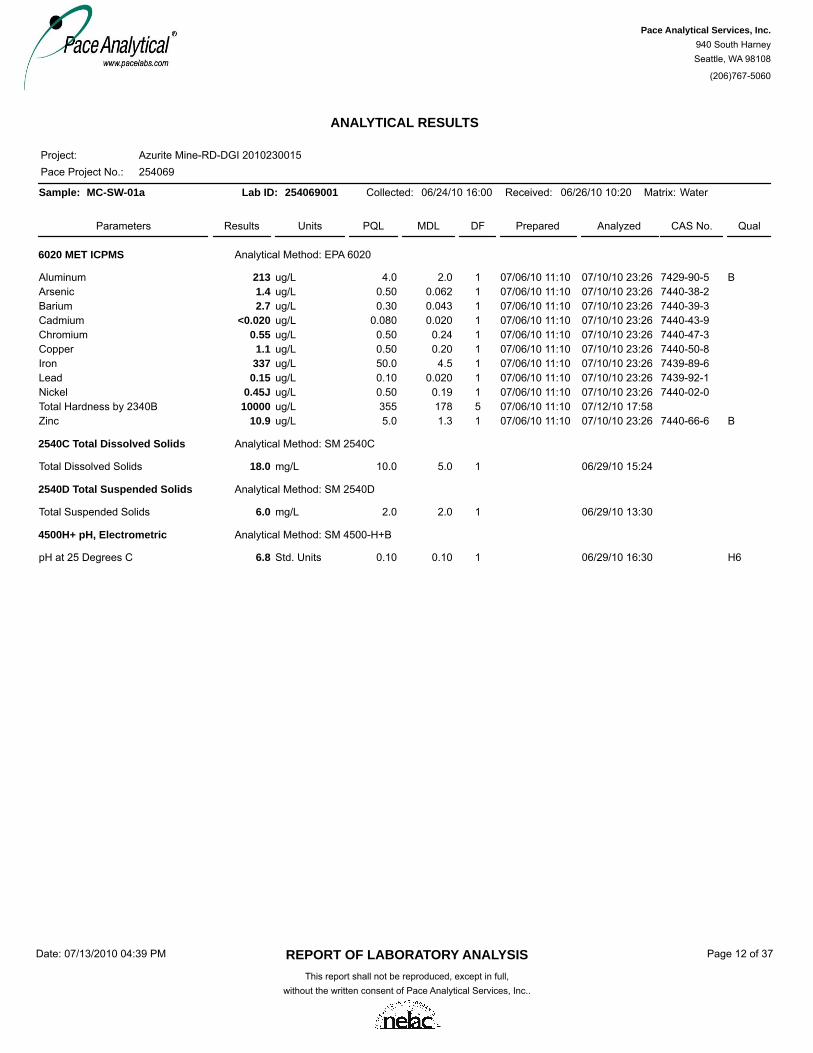
ANALYTICAL RESULTS
Pace Project No.:Project:
254069Azurite Mine-RD-DGI 2010230015
Sample: MC-SW-01a Lab ID: 254069001 Collected: 06/24/10 16:00 Received: 06/26/10 10:20 Matrix: Water
Parameters Results Units DF Prepared Analyzed CAS No. QualMDLPQL
6020 MET ICPMS Analytical Method: EPA 6020
Aluminum 213 ug/L 1 07/10/10 23:26 7429-90-5 B07/06/10 11:104.0 2.0Arsenic 1.4 ug/L 1 07/10/10 23:26 7440-38-207/06/10 11:100.50 0.062Barium 2.7 ug/L 1 07/10/10 23:26 7440-39-307/06/10 11:100.30 0.043Cadmium <0.020 ug/L 1 07/10/10 23:26 7440-43-907/06/10 11:100.080 0.020Chromium 0.55 ug/L 1 07/10/10 23:26 7440-47-307/06/10 11:100.50 0.24Copper 1.1 ug/L 1 07/10/10 23:26 7440-50-807/06/10 11:100.50 0.20Iron 337 ug/L 1 07/10/10 23:26 7439-89-607/06/10 11:1050.0 4.5Lead 0.15 ug/L 1 07/10/10 23:26 7439-92-107/06/10 11:100.10 0.020Nickel 0.45J ug/L 1 07/10/10 23:26 7440-02-007/06/10 11:100.50 0.19Total Hardness by 2340B 10000 ug/L 5 07/12/10 17:5807/06/10 11:10355 178Zinc 10.9 ug/L 1 07/10/10 23:26 7440-66-6 B07/06/10 11:105.0 1.3
2540C Total Dissolved Solids Analytical Method: SM 2540C
Total Dissolved Solids 18.0 mg/L 1 06/29/10 15:2410.0 5.0
2540D Total Suspended Solids Analytical Method: SM 2540D
Total Suspended Solids 6.0 mg/L 1 06/29/10 13:302.0 2.0
4500H+ pH, Electrometric Analytical Method: SM 4500-H+B
pH at 25 Degrees C 6.8 Std. Units 1 06/29/10 16:30 H60.10 0.10
REPORT OF LABORATORY ANALYSISThis report shall not be reproduced, except in full,
without the written consent of Pace Analytical Services, Inc..
Date: 07/13/2010 04:39 PM Page 12 of 37
Pace Analytical Services, Inc.940 South HarneySeattle, WA 98108
(206)767-5060

ANALYTICAL RESULTS
Pace Project No.:Project:
254069Azurite Mine-RD-DGI 2010230015
Sample: MC-SW-01b Lab ID: 254069002 Collected: 06/24/10 15:00 Received: 06/26/10 10:20 Matrix: Water
Parameters Results Units DF Prepared Analyzed CAS No. QualMDLPQL
6020 MET ICPMS Analytical Method: EPA 6020
Aluminum 425 ug/L 1 07/10/10 23:34 7429-90-5 B07/06/10 11:104.0 2.0Arsenic 1.6 ug/L 1 07/10/10 23:34 7440-38-207/06/10 11:100.50 0.062Barium 3.9 ug/L 1 07/10/10 23:34 7440-39-307/06/10 11:100.30 0.043Cadmium <0.020 ug/L 1 07/10/10 23:34 7440-43-907/06/10 11:100.080 0.020Chromium 1.2 ug/L 1 07/10/10 23:34 7440-47-307/06/10 11:100.50 0.24Copper 2.4 ug/L 1 07/10/10 23:34 7440-50-807/06/10 11:100.50 0.20Iron 695 ug/L 1 07/10/10 23:34 7439-89-607/06/10 11:1050.0 4.5Lead 0.19 ug/L 1 07/10/10 23:34 7439-92-107/06/10 11:100.10 0.020Nickel 0.84 ug/L 1 07/10/10 23:34 7440-02-007/06/10 11:100.50 0.19Total Hardness by 2340B 10900 ug/L 5 07/12/10 18:0207/06/10 11:10355 178Zinc 11.6 ug/L 1 07/10/10 23:34 7440-66-6 B07/06/10 11:105.0 1.3
2540C Total Dissolved Solids Analytical Method: SM 2540C
Total Dissolved Solids 29.0 mg/L 1 06/29/10 15:2410.0 5.0
2540D Total Suspended Solids Analytical Method: SM 2540D
Total Suspended Solids 14.0 mg/L 1 06/29/10 13:302.0 2.0
4500H+ pH, Electrometric Analytical Method: SM 4500-H+B
pH at 25 Degrees C 5.6 Std. Units 1 06/30/10 18:22 H60.10 0.10
REPORT OF LABORATORY ANALYSISThis report shall not be reproduced, except in full,
without the written consent of Pace Analytical Services, Inc..
Date: 07/13/2010 04:39 PM Page 13 of 37
Pace Analytical Services, Inc.940 South HarneySeattle, WA 98108
(206)767-5060
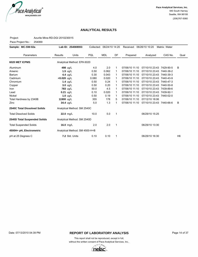
ANALYTICAL RESULTS
Pace Project No.:Project:
254069Azurite Mine-RD-DGI 2010230015
Sample: MC-SW-02a Lab ID: 254069003 Collected: 06/24/10 14:20 Received: 06/26/10 10:20 Matrix: Water
Parameters Results Units DF Prepared Analyzed CAS No. QualMDLPQL
6020 MET ICPMS Analytical Method: EPA 6020
Aluminum 498 ug/L 1 07/10/10 23:43 7429-90-5 B07/06/10 11:104.0 2.0Arsenic 1.5 ug/L 1 07/10/10 23:43 7440-38-207/06/10 11:100.50 0.062Barium 4.4 ug/L 1 07/10/10 23:43 7440-39-307/06/10 11:100.30 0.043Cadmium <0.020 ug/L 1 07/10/10 23:43 7440-43-907/06/10 11:100.080 0.020Chromium 1.4 ug/L 1 07/10/10 23:43 7440-47-307/06/10 11:100.50 0.24Copper 3.0 ug/L 1 07/10/10 23:43 7440-50-807/06/10 11:100.50 0.20Iron 783 ug/L 1 07/10/10 23:43 7439-89-607/06/10 11:1050.0 4.5Lead 0.21 ug/L 1 07/10/10 23:43 7439-92-107/06/10 11:100.10 0.020Nickel 1.0 ug/L 1 07/10/10 23:43 7440-02-007/06/10 11:100.50 0.19Total Hardness by 2340B 11900 ug/L 5 07/12/10 18:0607/06/10 11:10355 178Zinc 34.4 ug/L 1 07/10/10 23:43 7440-66-6 B07/06/10 11:105.0 1.3
2540C Total Dissolved Solids Analytical Method: SM 2540C
Total Dissolved Solids 22.0 mg/L 1 06/29/10 15:2510.0 5.0
2540D Total Suspended Solids Analytical Method: SM 2540D
Total Suspended Solids 16.0 mg/L 1 06/29/10 13:302.0 2.0
4500H+ pH, Electrometric Analytical Method: SM 4500-H+B
pH at 25 Degrees C 7.2 Std. Units 1 06/29/10 16:30 H60.10 0.10
REPORT OF LABORATORY ANALYSISThis report shall not be reproduced, except in full,
without the written consent of Pace Analytical Services, Inc..
Date: 07/13/2010 04:39 PM Page 14 of 37
Pace Analytical Services, Inc.940 South HarneySeattle, WA 98108
(206)767-5060

ANALYTICAL RESULTS
Pace Project No.:Project:
254069Azurite Mine-RD-DGI 2010230015
Sample: MC-SW-03 Lab ID: 254069004 Collected: 06/24/10 11:30 Received: 06/26/10 10:20 Matrix: Water
Parameters Results Units DF Prepared Analyzed CAS No. QualMDLPQL
6020 MET ICPMS Analytical Method: EPA 6020
Aluminum 724 ug/L 1 07/10/10 23:51 7429-90-5 B07/06/10 11:104.0 2.0Arsenic 2.9 ug/L 1 07/10/10 23:51 7440-38-207/06/10 11:100.50 0.062Barium 5.0 ug/L 1 07/10/10 23:51 7440-39-307/06/10 11:100.30 0.043Cadmium 0.040J ug/L 1 07/10/10 23:51 7440-43-907/06/10 11:100.080 0.020Chromium 2.1 ug/L 1 07/10/10 23:51 7440-47-307/06/10 11:100.50 0.24Copper 3.9 ug/L 1 07/10/10 23:51 7440-50-807/06/10 11:100.50 0.20Iron 1140 ug/L 1 07/10/10 23:51 7439-89-607/06/10 11:1050.0 4.5Lead 0.41 ug/L 1 07/10/10 23:51 7439-92-107/06/10 11:100.10 0.020Nickel 1.3 ug/L 1 07/10/10 23:51 7440-02-007/06/10 11:100.50 0.19Total Hardness by 2340B 13300 ug/L 5 07/12/10 18:1007/06/10 11:10355 178Zinc 20.8 ug/L 1 07/10/10 23:51 7440-66-6 B07/06/10 11:105.0 1.3
2540C Total Dissolved Solids Analytical Method: SM 2540C
Total Dissolved Solids 17.0 mg/L 1 06/29/10 15:2610.0 5.0
2540D Total Suspended Solids Analytical Method: SM 2540D
Total Suspended Solids 35.0 mg/L 1 06/29/10 13:302.0 2.0
4500H+ pH, Electrometric Analytical Method: SM 4500-H+B
pH at 25 Degrees C 6.9 Std. Units 1 06/29/10 16:30 H60.10 0.10
REPORT OF LABORATORY ANALYSISThis report shall not be reproduced, except in full,
without the written consent of Pace Analytical Services, Inc..
Date: 07/13/2010 04:39 PM Page 15 of 37
Pace Analytical Services, Inc.940 South HarneySeattle, WA 98108
(206)767-5060

ANALYTICAL RESULTS
Pace Project No.:Project:
254069Azurite Mine-RD-DGI 2010230015
Sample: MC-SW-04 Lab ID: 254069005 Collected: 06/24/10 10:35 Received: 06/26/10 10:20 Matrix: Water
Parameters Results Units DF Prepared Analyzed CAS No. QualMDLPQL
6020 MET ICPMS Analytical Method: EPA 6020
Aluminum 702 ug/L 1 07/11/10 00:00 7429-90-5 B07/06/10 11:104.0 2.0Arsenic 2.5 ug/L 1 07/11/10 00:00 7440-38-207/06/10 11:100.50 0.062Barium 5.4 ug/L 1 07/11/10 00:00 7440-39-307/06/10 11:100.30 0.043Cadmium 0.048J ug/L 1 07/11/10 00:00 7440-43-907/06/10 11:100.080 0.020Chromium 2.0 ug/L 1 07/11/10 00:00 7440-47-307/06/10 11:100.50 0.24Copper 5.0 ug/L 1 07/11/10 00:00 7440-50-807/06/10 11:100.50 0.20Iron 1100 ug/L 1 07/11/10 00:00 7439-89-607/06/10 11:1050.0 4.5Lead 0.44 ug/L 1 07/11/10 00:00 7439-92-107/06/10 11:100.10 0.020Nickel 1.6 ug/L 1 07/11/10 00:00 7440-02-007/06/10 11:100.50 0.19Total Hardness by 2340B 16800 ug/L 5 07/12/10 18:1407/06/10 11:10355 178Zinc 33.1 ug/L 1 07/11/10 00:00 7440-66-6 B07/06/10 11:105.0 1.3
2540C Total Dissolved Solids Analytical Method: SM 2540C
Total Dissolved Solids 26.0 mg/L 1 06/29/10 15:2710.0 5.0
2540D Total Suspended Solids Analytical Method: SM 2540D
Total Suspended Solids 12.0 mg/L 1 06/29/10 13:302.0 2.0
4500H+ pH, Electrometric Analytical Method: SM 4500-H+B
pH at 25 Degrees C 6.6 Std. Units 1 06/29/10 16:30 H60.10 0.10
REPORT OF LABORATORY ANALYSISThis report shall not be reproduced, except in full,
without the written consent of Pace Analytical Services, Inc..
Date: 07/13/2010 04:39 PM Page 16 of 37
Pace Analytical Services, Inc.940 South HarneySeattle, WA 98108
(206)767-5060

ANALYTICAL RESULTS
Pace Project No.:Project:
254069Azurite Mine-RD-DGI 2010230015
Sample: MC-SW-05 Lab ID: 254069006 Collected: 06/24/10 09:45 Received: 06/26/10 10:20 Matrix: Water
Parameters Results Units DF Prepared Analyzed CAS No. QualMDLPQL
6020 MET ICPMS Analytical Method: EPA 6020
Aluminum 784 ug/L 1 07/11/10 00:21 7429-90-5 B07/06/10 11:104.0 2.0Arsenic 3.3 ug/L 1 07/11/10 00:21 7440-38-207/06/10 11:100.50 0.062Barium 5.0 ug/L 1 07/11/10 00:21 7440-39-307/06/10 11:100.30 0.043Cadmium 0.041J ug/L 1 07/11/10 00:21 7440-43-907/06/10 11:100.080 0.020Chromium 2.1 ug/L 1 07/11/10 00:21 7440-47-307/06/10 11:100.50 0.24Copper 5.2 ug/L 1 07/11/10 00:21 7440-50-807/06/10 11:100.50 0.20Iron 1160 ug/L 1 07/11/10 00:21 7439-89-607/06/10 11:1050.0 4.5Lead 0.48 ug/L 1 07/11/10 00:21 7439-92-107/06/10 11:100.10 0.020Nickel 1.4 ug/L 1 07/11/10 00:21 7440-02-007/06/10 11:100.50 0.19Total Hardness by 2340B 17000 ug/L 5 07/12/10 18:3107/06/10 11:10355 178Zinc 9.3 ug/L 1 07/11/10 00:21 7440-66-6 B07/06/10 11:105.0 1.3
2540C Total Dissolved Solids Analytical Method: SM 2540C
Total Dissolved Solids 17.0 mg/L 1 06/29/10 15:2810.0 5.0
2540D Total Suspended Solids Analytical Method: SM 2540D
Total Suspended Solids 16.0 mg/L 1 06/29/10 13:302.0 2.0
4500H+ pH, Electrometric Analytical Method: SM 4500-H+B
pH at 25 Degrees C 7.5 Std. Units 1 06/29/10 16:30 H60.10 0.10
REPORT OF LABORATORY ANALYSISThis report shall not be reproduced, except in full,
without the written consent of Pace Analytical Services, Inc..
Date: 07/13/2010 04:39 PM Page 17 of 37
Pace Analytical Services, Inc.940 South HarneySeattle, WA 98108
(206)767-5060

ANALYTICAL RESULTS
Pace Project No.:Project:
254069Azurite Mine-RD-DGI 2010230015
Sample: MC-SW-06 Lab ID: 254069007 Collected: 06/23/10 12:40 Received: 06/26/10 10:20 Matrix: Water
Parameters Results Units DF Prepared Analyzed CAS No. QualMDLPQL
6020 MET ICPMS Analytical Method: EPA 6020
Aluminum 398 ug/L 1 07/11/10 00:29 7429-90-5 B07/06/10 11:104.0 2.0Arsenic 2.0 ug/L 1 07/11/10 00:29 7440-38-207/06/10 11:100.50 0.062Barium 3.1 ug/L 1 07/11/10 00:29 7440-39-307/06/10 11:100.30 0.043Cadmium 0.035J ug/L 1 07/11/10 00:29 7440-43-907/06/10 11:100.080 0.020Chromium 1.1 ug/L 1 07/11/10 00:29 7440-47-307/06/10 11:100.50 0.24Copper 2.7 ug/L 1 07/11/10 00:29 7440-50-807/06/10 11:100.50 0.20Iron 499 ug/L 1 07/11/10 00:29 7439-89-607/06/10 11:1050.0 4.5Lead 0.36 ug/L 1 07/11/10 00:29 7439-92-107/06/10 11:100.10 0.020Nickel 0.68 ug/L 1 07/11/10 00:29 7440-02-007/06/10 11:100.50 0.19Total Hardness by 2340B 24000 ug/L 5 07/12/10 18:3507/06/10 11:10355 178Zinc 13.5 ug/L 1 07/11/10 00:29 7440-66-6 B07/06/10 11:105.0 1.3
2540C Total Dissolved Solids Analytical Method: SM 2540C
Total Dissolved Solids 31.0 mg/L 1 06/29/10 15:2110.0 5.0
2540D Total Suspended Solids Analytical Method: SM 2540D
Total Suspended Solids 4.0 mg/L 1 06/29/10 13:302.0 2.0
4500H+ pH, Electrometric Analytical Method: SM 4500-H+B
pH at 25 Degrees C 7.5 Std. Units 1 06/29/10 16:30 H60.10 0.10
REPORT OF LABORATORY ANALYSISThis report shall not be reproduced, except in full,
without the written consent of Pace Analytical Services, Inc..
Date: 07/13/2010 04:39 PM Page 18 of 37
Pace Analytical Services, Inc.940 South HarneySeattle, WA 98108
(206)767-5060

ANALYTICAL RESULTS
Pace Project No.:Project:
254069Azurite Mine-RD-DGI 2010230015
Sample: CC-SW-01 Lab ID: 254069008 Collected: 06/23/10 11:40 Received: 06/26/10 10:20 Matrix: Water
Parameters Results Units DF Prepared Analyzed CAS No. QualMDLPQL
6020 MET ICPMS Analytical Method: EPA 6020
Aluminum 185 ug/L 1 07/11/10 00:37 7429-90-5 B07/06/10 11:104.0 2.0Arsenic 1.3 ug/L 1 07/11/10 00:37 7440-38-207/06/10 11:100.50 0.062Barium 6.5 ug/L 1 07/11/10 00:37 7440-39-307/06/10 11:100.30 0.043Cadmium <0.020 ug/L 1 07/11/10 00:37 7440-43-907/06/10 11:100.080 0.020Chromium 0.32J ug/L 1 07/11/10 00:37 7440-47-307/06/10 11:100.50 0.24Copper 0.60 ug/L 1 07/11/10 00:37 7440-50-807/06/10 11:100.50 0.20Iron 200 ug/L 1 07/11/10 00:37 7439-89-607/06/10 11:1050.0 4.5Lead 0.085J ug/L 1 07/11/10 00:37 7439-92-107/06/10 11:100.10 0.020Nickel 0.25J ug/L 1 07/11/10 00:37 7440-02-007/06/10 11:100.50 0.19Total Hardness by 2340B 33000 ug/L 5 07/12/10 18:3907/06/10 11:10355 178Zinc 15.8 ug/L 1 07/11/10 00:37 7440-66-6 B07/06/10 11:105.0 1.3
2540C Total Dissolved Solids Analytical Method: SM 2540C
Total Dissolved Solids 44.0 mg/L 1 06/29/10 15:2210.0 5.0
2540D Total Suspended Solids Analytical Method: SM 2540D
Total Suspended Solids <2.0 mg/L 1 06/29/10 13:302.0 2.0
4500H+ pH, Electrometric Analytical Method: SM 4500-H+B
pH at 25 Degrees C 7.6 Std. Units 1 06/29/10 16:30 H60.10 0.10
REPORT OF LABORATORY ANALYSISThis report shall not be reproduced, except in full,
without the written consent of Pace Analytical Services, Inc..
Date: 07/13/2010 04:39 PM Page 19 of 37
Pace Analytical Services, Inc.940 South HarneySeattle, WA 98108
(206)767-5060

ANALYTICAL RESULTS
Pace Project No.:Project:
254069Azurite Mine-RD-DGI 2010230015
Sample: CC-SW-02 Lab ID: 254069009 Collected: 06/23/10 12:20 Received: 06/26/10 10:20 Matrix: Water
Parameters Results Units DF Prepared Analyzed CAS No. QualMDLPQL
6020 MET ICPMS Analytical Method: EPA 6020
Aluminum 382 ug/L 1 07/11/10 00:46 7429-90-5 B07/06/10 11:104.0 2.0Arsenic 2.1 ug/L 1 07/11/10 00:46 7440-38-207/06/10 11:100.50 0.062Barium 4.3 ug/L 1 07/11/10 00:46 7440-39-307/06/10 11:100.30 0.043Cadmium 0.021J ug/L 1 07/11/10 00:46 7440-43-907/06/10 11:100.080 0.020Chromium 1.0 ug/L 1 07/11/10 00:46 7440-47-307/06/10 11:100.50 0.24Copper 2.5 ug/L 1 07/11/10 00:46 7440-50-807/06/10 11:100.50 0.20Iron 458 ug/L 1 07/11/10 00:46 7439-89-607/06/10 11:1050.0 4.5Lead 0.32 ug/L 1 07/11/10 00:46 7439-92-107/06/10 11:100.10 0.020Nickel 0.60 ug/L 1 07/11/10 00:46 7440-02-007/06/10 11:100.50 0.19Total Hardness by 2340B 28300 ug/L 5 07/12/10 18:4407/06/10 11:10355 178Zinc 11.4 ug/L 1 07/11/10 00:46 7440-66-6 B,M007/06/10 11:105.0 1.3
2540C Total Dissolved Solids Analytical Method: SM 2540C
Total Dissolved Solids 33.0 mg/L 1 06/29/10 15:2310.0 5.0
2540D Total Suspended Solids Analytical Method: SM 2540D
Total Suspended Solids 8.0 mg/L 1 06/29/10 13:302.0 2.0
4500H+ pH, Electrometric Analytical Method: SM 4500-H+B
pH at 25 Degrees C 7.4 Std. Units 1 06/29/10 16:30 H60.10 0.10
REPORT OF LABORATORY ANALYSISThis report shall not be reproduced, except in full,
without the written consent of Pace Analytical Services, Inc..
Date: 07/13/2010 04:39 PM Page 20 of 37
Pace Analytical Services, Inc.940 South HarneySeattle, WA 98108
(206)767-5060

ANALYTICAL RESULTS
Pace Project No.:Project:
254069Azurite Mine-RD-DGI 2010230015
Sample: AM-AS-01 Lab ID: 254069010 Collected: 06/24/10 17:45 Received: 06/26/10 10:20 Matrix: Water
Parameters Results Units DF Prepared Analyzed CAS No. QualMDLPQL
6020 MET ICPMS Analytical Method: EPA 6020
Aluminum 90.9 ug/L 1 07/11/10 01:11 7429-90-5 B07/06/10 11:104.0 2.0Arsenic 29.2 ug/L 1 07/11/10 01:11 7440-38-207/06/10 11:100.50 0.062Barium 0.92 ug/L 1 07/11/10 01:11 7440-39-307/06/10 11:100.30 0.043Cadmium 0.17 ug/L 1 07/11/10 01:11 7440-43-907/06/10 11:100.080 0.020Calcium 19100 ug/L 1 07/11/10 01:11 7440-70-207/06/10 11:1020.0 5.0Chromium 0.28J ug/L 1 07/11/10 01:11 7440-47-307/06/10 11:100.50 0.24Copper 3.6 ug/L 1 07/11/10 01:11 7440-50-807/06/10 11:100.50 0.20Iron 504 ug/L 1 07/11/10 01:11 7439-89-607/06/10 11:1050.0 4.5Lead 0.066J ug/L 1 07/11/10 01:11 7439-92-107/06/10 11:100.10 0.020Nickel 1.0 ug/L 1 07/11/10 01:11 7440-02-007/06/10 11:100.50 0.19Potassium 157 ug/L 1 07/11/10 01:11 7440-09-7 B07/06/10 11:1020.0 5.1Sodium 651 ug/L 1 07/11/10 01:11 7440-23-507/06/10 11:1050.0 12.5Total Hardness by 2340B 53500 ug/L 1 07/11/10 01:1107/06/10 11:1071.0 35.5Zinc 53.1 ug/L 1 07/11/10 01:11 7440-66-6 B07/06/10 11:105.0 1.3
2320B Alkalinity Analytical Method: SM 2320B
Alkalinity, Total as CaCO3 41.8 mg/L 1 07/08/10 20:002.0 2.0
2540C Total Dissolved Solids Analytical Method: SM 2540C
Total Dissolved Solids 62.0 mg/L 1 06/29/10 15:2910.0 5.0
2540D Total Suspended Solids Analytical Method: SM 2540D
Total Suspended Solids <2.0 mg/L 1 06/29/10 13:302.0 2.0
4500H+ pH, Electrometric Analytical Method: SM 4500-H+B
pH at 25 Degrees C 7.4 Std. Units 1 06/29/10 16:30 H60.10 0.10
300.0 IC Anions 28 Days Analytical Method: EPA 300.0
Chloride 0.10J mg/L 1 07/03/10 17:51 16887-00-61.0 0.076Sulfate 11.0 mg/L 1 07/03/10 17:51 14808-79-81.0 0.17
REPORT OF LABORATORY ANALYSISThis report shall not be reproduced, except in full,
without the written consent of Pace Analytical Services, Inc..
Date: 07/13/2010 04:39 PM Page 21 of 37
Pace Analytical Services, Inc.940 South HarneySeattle, WA 98108
(206)767-5060

ANALYTICAL RESULTS
Pace Project No.:Project:
254069Azurite Mine-RD-DGI 2010230015
Sample: AM-SP-01 Lab ID: 254069011 Collected: 06/24/10 19:15 Received: 06/26/10 10:20 Matrix: Water
Parameters Results Units DF Prepared Analyzed CAS No. QualMDLPQL
6020 MET ICPMS Analytical Method: EPA 6020
Aluminum 284 ug/L 1 07/11/10 01:19 7429-90-5 B07/06/10 11:104.0 2.0Arsenic 2.5 ug/L 1 07/11/10 01:19 7440-38-207/06/10 11:100.50 0.062Barium 2.8 ug/L 1 07/11/10 01:19 7440-39-307/06/10 11:100.30 0.043Cadmium 0.28 ug/L 1 07/11/10 01:19 7440-43-907/06/10 11:100.080 0.020Calcium 20000 ug/L 1 07/11/10 01:19 7440-70-207/06/10 11:1020.0 5.0Chromium <0.24 ug/L 1 07/11/10 01:19 7440-47-307/06/10 11:100.50 0.24Copper 4.9 ug/L 1 07/11/10 01:19 7440-50-807/06/10 11:100.50 0.20Iron 14.2J ug/L 1 07/11/10 01:19 7439-89-607/06/10 11:1050.0 4.5Lead 0.056J ug/L 1 07/11/10 01:19 7439-92-107/06/10 11:100.10 0.020Nickel 3.8 ug/L 1 07/11/10 01:19 7440-02-007/06/10 11:100.50 0.19Potassium 616 ug/L 1 07/11/10 01:19 7440-09-7 B07/06/10 11:1020.0 5.1Sodium 1260 ug/L 1 07/11/10 01:19 7440-23-507/06/10 11:1050.0 12.5Total Hardness by 2340B 60400 ug/L 1 07/11/10 01:1907/06/10 11:1071.0 35.5Zinc 41.9 ug/L 1 07/11/10 01:19 7440-66-6 B07/06/10 11:105.0 1.3
2320B Alkalinity Analytical Method: SM 2320B
Alkalinity, Total as CaCO3 20.0 mg/L 1 07/08/10 20:002.0 2.0
2540C Total Dissolved Solids Analytical Method: SM 2540C
Total Dissolved Solids 83.0 mg/L 1 06/29/10 15:3010.0 5.0
2540D Total Suspended Solids Analytical Method: SM 2540D
Total Suspended Solids <2.0 mg/L 1 06/29/10 13:302.0 2.0
4500H+ pH, Electrometric Analytical Method: SM 4500-H+B
pH at 25 Degrees C 7.0 Std. Units 1 06/29/10 16:30 H60.10 0.10
300.0 IC Anions 28 Days Analytical Method: EPA 300.0
Chloride 6.2 mg/L 1 07/03/10 18:08 16887-00-61.0 0.076Sulfate 35.2 mg/L 20 07/08/10 20:47 14808-79-820.0 3.4
REPORT OF LABORATORY ANALYSISThis report shall not be reproduced, except in full,
without the written consent of Pace Analytical Services, Inc..
Date: 07/13/2010 04:39 PM Page 22 of 37
Pace Analytical Services, Inc.940 South HarneySeattle, WA 98108
(206)767-5060

ANALYTICAL RESULTS
Pace Project No.:Project:
254069Azurite Mine-RD-DGI 2010230015
Sample: AM-SP-02 Lab ID: 254069012 Collected: 06/24/10 18:40 Received: 06/26/10 10:20 Matrix: Water
Parameters Results Units DF Prepared Analyzed CAS No. QualMDLPQL
6020 MET ICPMS Analytical Method: EPA 6020
Aluminum 24800 ug/L 5 07/11/10 01:32 7429-90-5 B07/06/10 11:1020.0 10.0Arsenic 0.45J ug/L 1 07/11/10 01:28 7440-38-207/06/10 11:100.50 0.062Barium 14.3 ug/L 1 07/11/10 01:28 7440-39-307/06/10 11:100.30 0.043Cadmium 2.9 ug/L 1 07/11/10 01:28 7440-43-907/06/10 11:100.080 0.020Calcium 39300 ug/L 5 07/11/10 01:32 7440-70-207/06/10 11:10100 24.8Chromium 1.5 ug/L 1 07/11/10 01:28 7440-47-307/06/10 11:100.50 0.24Copper 592 ug/L 5 07/11/10 01:32 7440-50-807/06/10 11:102.5 1.0Iron 251 ug/L 1 07/11/10 01:28 7439-89-607/06/10 11:1050.0 4.5Lead 2.3 ug/L 1 07/11/10 01:28 7439-92-107/06/10 11:100.10 0.020Nickel 43.9 ug/L 1 07/11/10 01:28 7440-02-007/06/10 11:100.50 0.19Potassium 3200 ug/L 1 07/11/10 01:28 7440-09-7 B07/06/10 11:1020.0 5.1Sodium 4590 ug/L 1 07/11/10 01:28 7440-23-507/06/10 11:1050.0 12.5Total Hardness by 2340B 168000 ug/L 5 07/11/10 01:3207/06/10 11:10355 178Zinc 410 ug/L 1 07/11/10 01:28 7440-66-6 B07/06/10 11:105.0 1.3
2320B Alkalinity Analytical Method: SM 2320B
Alkalinity, Total as CaCO3 <2.0 mg/L 1 07/08/10 20:002.0 2.0
2540C Total Dissolved Solids Analytical Method: SM 2540C
Total Dissolved Solids 21.0 mg/L 1 06/29/10 15:3110.0 5.0
2540D Total Suspended Solids Analytical Method: SM 2540D
Total Suspended Solids 3.0 mg/L 1 06/29/10 13:302.0 2.0
4500H+ pH, Electrometric Analytical Method: SM 4500-H+B
pH at 25 Degrees C 3.9 Std. Units 1 06/30/10 18:22 H60.10 0.10
300.0 IC Anions 28 Days Analytical Method: EPA 300.0
Chloride 0.22J mg/L 1 07/07/10 12:39 16887-00-61.0 0.076Sulfate 337 mg/L 50 07/08/10 23:15 14808-79-850.0 8.5
REPORT OF LABORATORY ANALYSISThis report shall not be reproduced, except in full,
without the written consent of Pace Analytical Services, Inc..
Date: 07/13/2010 04:39 PM Page 23 of 37
Pace Analytical Services, Inc.940 South HarneySeattle, WA 98108
(206)767-5060

ANALYTICAL RESULTS
Pace Project No.:Project:
254069Azurite Mine-RD-DGI 2010230015
Sample: MC-SW-07 Lab ID: 254069013 Collected: 06/24/10 10:10 Received: 06/26/10 10:20 Matrix: Water
Parameters Results Units DF Prepared Analyzed CAS No. QualMDLPQL
6020 MET ICPMS Analytical Method: EPA 6020
Aluminum 662 ug/L 1 07/11/10 01:36 7429-90-5 B07/06/10 11:104.0 2.0Arsenic 2.3 ug/L 1 07/11/10 01:36 7440-38-207/06/10 11:100.50 0.062Barium 5.0 ug/L 1 07/11/10 01:36 7440-39-307/06/10 11:100.30 0.043Cadmium 0.028J ug/L 1 07/11/10 01:36 7440-43-907/06/10 11:100.080 0.020Chromium 1.9 ug/L 1 07/11/10 01:36 7440-47-307/06/10 11:100.50 0.24Copper 4.6 ug/L 1 07/11/10 01:36 7440-50-807/06/10 11:100.50 0.20Iron 1020 ug/L 1 07/11/10 01:36 7439-89-607/06/10 11:1050.0 4.5Lead 0.32 ug/L 1 07/11/10 01:36 7439-92-107/06/10 11:100.10 0.020Nickel 1.4 ug/L 1 07/11/10 01:36 7440-02-007/06/10 11:100.50 0.19Zinc 19.3 ug/L 1 07/11/10 01:36 7440-66-6 B07/06/10 11:105.0 1.3
REPORT OF LABORATORY ANALYSISThis report shall not be reproduced, except in full,
without the written consent of Pace Analytical Services, Inc..
Date: 07/13/2010 04:39 PM Page 24 of 37
Pace Analytical Services, Inc.940 South HarneySeattle, WA 98108
(206)767-5060

ANALYTICAL RESULTS
Pace Project No.:Project:
254069Azurite Mine-RD-DGI 2010230015
Sample: MC-SW-08 Lab ID: 254069014 Collected: 06/25/10 07:30 Received: 06/26/10 10:20 Matrix: Water
Parameters Results Units DF Prepared Analyzed CAS No. QualMDLPQL
6020 MET ICPMS Analytical Method: EPA 6020
Aluminum 7.8 ug/L 1 07/11/10 01:40 7429-90-5 B07/06/10 11:104.0 2.0Arsenic <0.062 ug/L 1 07/11/10 01:40 7440-38-207/06/10 11:100.50 0.062Barium 0.086J ug/L 1 07/11/10 01:40 7440-39-307/06/10 11:100.30 0.043Cadmium <0.020 ug/L 1 07/11/10 01:40 7440-43-907/06/10 11:100.080 0.020Chromium 0.27J ug/L 1 07/11/10 01:40 7440-47-307/06/10 11:100.50 0.24Copper 0.93 ug/L 1 07/11/10 01:40 7440-50-807/06/10 11:100.50 0.20Iron 5.1J ug/L 1 07/11/10 01:40 7439-89-607/06/10 11:1050.0 4.5Lead 0.12 ug/L 1 07/11/10 01:40 7439-92-107/06/10 11:100.10 0.020Nickel <0.19 ug/L 1 07/11/10 01:40 7440-02-007/06/10 11:100.50 0.19Zinc 6.3 ug/L 1 07/11/10 01:40 7440-66-6 B07/06/10 11:105.0 1.3
REPORT OF LABORATORY ANALYSISThis report shall not be reproduced, except in full,
without the written consent of Pace Analytical Services, Inc..
Date: 07/13/2010 04:39 PM Page 25 of 37
Pace Analytical Services, Inc.940 South HarneySeattle, WA 98108
(206)767-5060

ANALYTICAL RESULTS
Pace Project No.:Project:
254069Azurite Mine-RD-DGI 2010230015
Sample: MC-SW-02b Lab ID: 254069015 Collected: 06/24/10 13:15 Received: 06/26/10 10:20 Matrix: Water
Parameters Results Units DF Prepared Analyzed CAS No. QualMDLPQL
6020 MET ICPMS Analytical Method: EPA 6020
Aluminum 681 ug/L 1 07/11/10 01:44 7429-90-5 B07/06/10 11:104.0 2.0Arsenic 2.2 ug/L 1 07/11/10 01:44 7440-38-207/06/10 11:100.50 0.062Barium 5.2 ug/L 1 07/11/10 01:44 7440-39-307/06/10 11:100.30 0.043Cadmium 0.038J ug/L 1 07/11/10 01:44 7440-43-907/06/10 11:100.080 0.020Chromium 1.8 ug/L 1 07/11/10 01:44 7440-47-307/06/10 11:100.50 0.24Copper 3.8 ug/L 1 07/11/10 01:44 7440-50-807/06/10 11:100.50 0.20Iron 1110 ug/L 1 07/11/10 01:44 7439-89-607/06/10 11:1050.0 4.5Lead 0.28 ug/L 1 07/11/10 01:44 7439-92-107/06/10 11:100.10 0.020Nickel 1.3 ug/L 1 07/11/10 01:44 7440-02-007/06/10 11:100.50 0.19Zinc 13.2 ug/L 1 07/11/10 01:44 7440-66-6 B07/06/10 11:105.0 1.3
2540C Total Dissolved Solids Analytical Method: SM 2540C
Total Dissolved Solids 19.0 mg/L 1 06/29/10 15:3210.0 5.0
2540D Total Suspended Solids Analytical Method: SM 2540D
Total Suspended Solids 17.0 mg/L 1 06/29/10 13:302.0 2.0
4500H+ pH, Electrometric Analytical Method: SM 4500-H+B
pH at 25 Degrees C 7.1 Std. Units 1 06/29/10 16:30 H60.10 0.10
REPORT OF LABORATORY ANALYSISThis report shall not be reproduced, except in full,
without the written consent of Pace Analytical Services, Inc..
Date: 07/13/2010 04:39 PM Page 26 of 37
Pace Analytical Services, Inc.940 South HarneySeattle, WA 98108
(206)767-5060

QUALITY CONTROL DATA
Pace Project No.:Project:
254069Azurite Mine-RD-DGI 2010230015
QC Batch:QC Batch Method:
Analysis Method:Analysis Description:
ICPM/21220EPA 6020
EPA 60206020 MET
Associated Lab Samples: 254069001, 254069002, 254069003, 254069004, 254069005, 254069006, 254069007, 254069008, 254069009
Parameter UnitsBlankResult
ReportingLimit Qualifiers
METHOD BLANK: 817215
Associated Lab Samples: 254069001, 254069002, 254069003, 254069004, 254069005, 254069006, 254069007, 254069008, 254069009,254069010, 254069011, 254069012, 254069013, 254069014, 254069015
Matrix: Water
Analyzed
Aluminum ug/L 2.9J 4.0 07/12/10 17:37Arsenic ug/L <0.062 0.50 07/12/10 17:37Barium ug/L <0.043 0.30 07/12/10 17:37Cadmium ug/L <0.020 0.080 07/12/10 17:37Calcium ug/L <5.0 20.0 07/12/10 17:37Chromium ug/L <0.24 0.50 07/12/10 17:37Copper ug/L <0.20 0.50 07/12/10 17:37Iron ug/L <4.5 50.0 07/12/10 17:37Lead ug/L <0.020 0.10 07/12/10 17:37Nickel ug/L <0.19 0.50 07/12/10 17:37Potassium ug/L 7.8J 20.0 07/12/10 17:37Sodium ug/L <12.5 50.0 07/12/10 17:37Total Hardness by 2340B ug/L <35.5 71.0 07/12/10 17:37Zinc ug/L 1.9J 5.0 07/12/10 17:37
Parameter UnitsLCS
Result% RecLimits Qualifiers% RecConc.
817216LABORATORY CONTROL SAMPLE:LCSSpike
Aluminum ug/L 84.380 105 80-120Arsenic ug/L 81.080 101 80-120Barium ug/L 80.280 100 80-120Cadmium ug/L 80.280 100 80-120Calcium ug/L 10501000 105 80-120Chromium ug/L 81.180 101 80-120Copper ug/L 84.280 105 80-120Iron ug/L 10201000 102 80-120Lead ug/L 77.680 97 80-120Nickel ug/L 84.180 105 80-120Potassium ug/L 10401000 104 80-120Sodium ug/L 10001000 100 80-120Total Hardness by 2340B ug/L 6790Zinc ug/L 80.180 100 80-120
Parameter UnitsMS
Result% RecLimits Qual% RecConc.
817217MATRIX SPIKE & MATRIX SPIKE DUPLICATE:
MSSpikeResult
254060001
817218
MSDResult
MSD% Rec RPD RPD
MaxMSDMSSpikeConc.
Aluminum ug/L 80 98 75-12599 .4 2080<20.0 95.6 95.9Arsenic ug/L 80 104 75-125105 .7 208068.4 151 152
REPORT OF LABORATORY ANALYSISThis report shall not be reproduced, except in full,
without the written consent of Pace Analytical Services, Inc..
Date: 07/13/2010 04:39 PM Page 27 of 37
Pace Analytical Services, Inc.940 South HarneySeattle, WA 98108
(206)767-5060

QUALITY CONTROL DATA
Pace Project No.:Project:
254069Azurite Mine-RD-DGI 2010230015
Parameter UnitsMS
Result% RecLimits Qual% RecConc.
817217MATRIX SPIKE & MATRIX SPIKE DUPLICATE:
MSSpikeResult
254060001
817218
MSDResult
MSD% Rec RPD RPD
MaxMSDMSSpikeConc.
Barium ug/L 80 94 75-125103 4 208091.0 166 173Cadmium ug/L 80 96 75-125101 5 20800.053J 77.0 81.2Calcium ug/L M01000 115 75-125367 3 20100082800 84000 86500Chromium ug/L 80 100 75-125103 3 20800.51 80.7 83.1Copper ug/L 80 104 75-125106 2 20804.4 87.4 88.9Iron ug/L 1000 100 75-125106 5 201000107 1110 1160Lead ug/L 80 95 75-12598 3 20800.83 76.9 79.0Nickel ug/L 80 104 75-125105 .8 20802.4 85.4 86.1Potassium ug/L 1000 106 75-125108 .6 2010003000 4060 4080Sodium ug/L M01000 114 75-125138 1 20100015300 16400 16700Total Hardness by 2340B ug/L 3 20325000 332000 343000Zinc ug/L 80 101 75-125105 4 208011.4 91.9 95.6
Parameter UnitsMS
Result% RecLimits Qualifiers% RecConc.
817219MATRIX SPIKE SAMPLE:MSSpike
Result254069009
Aluminum ug/L 47080 111 75-125382Arsenic ug/L 80.680 98 75-1252.1Barium ug/L 84.080 100 75-1254.3Cadmium ug/L 78.180 98 75-1250.021JCalcium ug/L 9900 M01000 47 75-125Chromium ug/L 81.680 101 75-1251.0Copper ug/L 85.280 103 75-1252.5Iron ug/L 14501000 99 75-125458Lead ug/L 75.980 94 75-1250.32Nickel ug/L 84.180 104 75-1250.60Potassium ug/L 14301000 102 75-125410Sodium ug/L 17501000 103 75-125715Total Hardness by 2340B ug/L 3370028300Zinc ug/L 113 M080 127 75-12511.4
REPORT OF LABORATORY ANALYSISThis report shall not be reproduced, except in full,
without the written consent of Pace Analytical Services, Inc..
Date: 07/13/2010 04:39 PM Page 28 of 37
Pace Analytical Services, Inc.940 South HarneySeattle, WA 98108
(206)767-5060

QUALITY CONTROL DATA
Pace Project No.:Project:
254069Azurite Mine-RD-DGI 2010230015
QC Batch:QC Batch Method:
Analysis Method:Analysis Description:
WET/2129SM 2320B
SM 2320B2320B Alkalinity
Associated Lab Samples: 254069010, 254069011, 254069012
Parameter UnitsBlankResult
ReportingLimit Qualifiers
METHOD BLANK: 32404
Associated Lab Samples: 254069010, 254069011, 254069012
Matrix: Water
Analyzed
Alkalinity, Total as CaCO3 mg/L <2.0 2.0 07/08/10 20:00
Parameter UnitsLCS
Result% RecLimits Qualifiers% RecConc.
32405LABORATORY CONTROL SAMPLE:LCSSpike
Alkalinity, Total as CaCO3 mg/L 96.9100 97 90-110
Parameter UnitsDup
ResultMaxRPD QualifiersRPDResult
25406901032406SAMPLE DUPLICATE:
Alkalinity, Total as CaCO3 mg/L 41.8 0 1041.8
Parameter UnitsDup
ResultMaxRPD QualifiersRPDResult
25412704532906SAMPLE DUPLICATE:
Alkalinity, Total as CaCO3 mg/L <2.0 10<2.0
REPORT OF LABORATORY ANALYSISThis report shall not be reproduced, except in full,
without the written consent of Pace Analytical Services, Inc..
Date: 07/13/2010 04:39 PM Page 29 of 37
Pace Analytical Services, Inc.940 South HarneySeattle, WA 98108
(206)767-5060

QUALITY CONTROL DATA
Pace Project No.:Project:
254069Azurite Mine-RD-DGI 2010230015
QC Batch:QC Batch Method:
Analysis Method:Analysis Description:
WET/2110SM 2540C
SM 2540C2540C Total Dissolved Solids
Associated Lab Samples: 254069001, 254069002, 254069003, 254069004, 254069005, 254069006, 254069007, 254069008, 254069009,254069010, 254069011, 254069012, 254069015
Parameter UnitsBlankResult
ReportingLimit Qualifiers
METHOD BLANK: 31624
Associated Lab Samples: 254069001, 254069002, 254069003, 254069004, 254069005, 254069006, 254069007, 254069008, 254069009,254069010, 254069011, 254069012, 254069015
Matrix: Water
Analyzed
Total Dissolved Solids mg/L <5.0 10.0 06/29/10 15:20
Parameter UnitsLCS
Result% RecLimits Qualifiers% RecConc.
31625LABORATORY CONTROL SAMPLE:LCSSpike
Total Dissolved Solids mg/L 296300 99 80-120
Parameter UnitsDup
ResultMaxRPD QualifiersRPDResult
25406900731626SAMPLE DUPLICATE:
Total Dissolved Solids mg/L 23.0 D830 2031.0
REPORT OF LABORATORY ANALYSISThis report shall not be reproduced, except in full,
without the written consent of Pace Analytical Services, Inc..
Date: 07/13/2010 04:39 PM Page 30 of 37
Pace Analytical Services, Inc.940 South HarneySeattle, WA 98108
(206)767-5060

QUALITY CONTROL DATA
Pace Project No.:Project:
254069Azurite Mine-RD-DGI 2010230015
QC Batch:QC Batch Method:
Analysis Method:Analysis Description:
WET/2109SM 2540D
SM 2540D2540D Total Suspended Solids
Associated Lab Samples: 254069001, 254069002, 254069003, 254069004, 254069005, 254069006, 254069007, 254069008, 254069009,254069010, 254069011, 254069012, 254069015
Parameter UnitsBlankResult
ReportingLimit Qualifiers
METHOD BLANK: 31621
Associated Lab Samples: 254069001, 254069002, 254069003, 254069004, 254069005, 254069006, 254069007, 254069008, 254069009,254069010, 254069011, 254069012, 254069015
Matrix: Water
Analyzed
Total Suspended Solids mg/L <2.0 2.0 06/29/10 13:30
Parameter UnitsDup
ResultMaxRPD QualifiersRPDResult
25406900731622SAMPLE DUPLICATE:
Total Suspended Solids mg/L 6.0 D840 204.0
Parameter UnitsDup
ResultMaxRPD QualifiersRPDResult
25406900631623SAMPLE DUPLICATE:
Total Suspended Solids mg/L 12.0 D629 2016.0
REPORT OF LABORATORY ANALYSISThis report shall not be reproduced, except in full,
without the written consent of Pace Analytical Services, Inc..
Date: 07/13/2010 04:39 PM Page 31 of 37
Pace Analytical Services, Inc.940 South HarneySeattle, WA 98108
(206)767-5060

QUALITY CONTROL DATA
Pace Project No.:Project:
254069Azurite Mine-RD-DGI 2010230015
QC Batch:QC Batch Method:
Analysis Method:Analysis Description:
WET/2111SM 4500-H+B
SM 4500-H+B4500H+B pH
Associated Lab Samples: 254069001, 254069003, 254069004, 254069005, 254069006, 254069007, 254069008, 254069009, 254069010,254069011, 254069015
Parameter UnitsDup
ResultMaxRPD QualifiersRPDResult
25406900831628SAMPLE DUPLICATE:
pH at 25 Degrees C Std. Units 7.6 H6.3 107.6
Parameter UnitsDup
ResultMaxRPD QualifiersRPDResult
25406901031629SAMPLE DUPLICATE:
pH at 25 Degrees C Std. Units 7.4 H6.9 107.4
REPORT OF LABORATORY ANALYSISThis report shall not be reproduced, except in full,
without the written consent of Pace Analytical Services, Inc..
Date: 07/13/2010 04:39 PM Page 32 of 37
Pace Analytical Services, Inc.940 South HarneySeattle, WA 98108
(206)767-5060

QUALITY CONTROL DATA
Pace Project No.:Project:
254069Azurite Mine-RD-DGI 2010230015
QC Batch:QC Batch Method:
Analysis Method:Analysis Description:
WET/2117SM 4500-H+B
SM 4500-H+B4500H+B pH
Associated Lab Samples: 254069002, 254069012
Parameter UnitsDup
ResultMaxRPD QualifiersRPDResult
25406900231907SAMPLE DUPLICATE:
pH at 25 Degrees C Std. Units 5.5 H62 105.6
REPORT OF LABORATORY ANALYSISThis report shall not be reproduced, except in full,
without the written consent of Pace Analytical Services, Inc..
Date: 07/13/2010 04:39 PM Page 33 of 37
Pace Analytical Services, Inc.940 South HarneySeattle, WA 98108
(206)767-5060

QUALITY CONTROL DATA
Pace Project No.:Project:
254069Azurite Mine-RD-DGI 2010230015
QC Batch:QC Batch Method:
Analysis Method:Analysis Description:
WETA/1602EPA 300.0
EPA 300.0300.0 IC Anions
Associated Lab Samples: 254069010, 254069011, 254069012
Parameter UnitsBlankResult
ReportingLimit Qualifiers
METHOD BLANK: 32286
Associated Lab Samples: 254069010, 254069011, 254069012
Matrix: Water
Analyzed
Chloride mg/L <0.076 1.0 07/03/10 16:24Sulfate mg/L <0.17 1.0 07/03/10 16:24
Parameter UnitsLCS
Result% RecLimits Qualifiers% RecConc.
32287LABORATORY CONTROL SAMPLE:LCSSpike
Chloride mg/L 4.75 95 90-110Sulfate mg/L 15.515 104 90-110
Parameter UnitsMS
Result% RecLimits Qual% RecConc.
32288MATRIX SPIKE & MATRIX SPIKE DUPLICATE:
MSSpikeResult
254052001
32289
MSDResult
MSD% Rec RPD RPD
MaxMSDMSSpikeConc.
Chloride mg/L M1100 117 90-110118 .6 1110056.8 174 175Sulfate mg/L M1300 119 90-110122 2 1030069400
ug/L426 436
REPORT OF LABORATORY ANALYSISThis report shall not be reproduced, except in full,
without the written consent of Pace Analytical Services, Inc..
Date: 07/13/2010 04:39 PM Page 34 of 37
Pace Analytical Services, Inc.940 South HarneySeattle, WA 98108
(206)767-5060

QUALIFIERS
Pace Project No.:Project:
254069Azurite Mine-RD-DGI 2010230015
DEFINITIONS
DF - Dilution Factor, if reported, represents the factor applied to the reported data due to changes in sample preparation, dilution ofthe sample aliquot, or moisture content.ND - Not Detected at or above adjusted reporting limit.J - Estimated concentration above the adjusted method detection limit and below the adjusted reporting limit.MDL - Adjusted Method Detection Limit.S - Surrogate1,2-Diphenylhydrazine (8270 listed analyte) decomposes to Azobenzene.Consistent with EPA guidelines, unrounded data are displayed and have been used to calculate % recovery and RPD values.LCS(D) - Laboratory Control Sample (Duplicate)MS(D) - Matrix Spike (Duplicate)DUP - Sample DuplicateRPD - Relative Percent DifferenceN-Nitrosodiphenylamine decomposes and cannot be separated from Diphenylamine using Method 8270. The result reported foreach analyte is a combined concentration.Pace Analytical is NELAP accredited. Contact your Pace PM for the current list of accredited analytes.
LABORATORIES
Pace Analytical Services - MinneapolisPASI-MPace Analytical Services - SeattlePASI-S
ANALYTE QUALIFIERS
Analyte was detected in the associated method blank.BThe relative percent difference (RPD) between the sample and sample duplicate exceeded laboratory control limits.D6The sample and duplicate results for this parameter are less than 5 times the reporting limit, the RPD may not bestatistically valid.
D8
Analysis initiated more than 15 minutes after sample collection.H6Matrix spike recovery and/or matrix spike duplicate recovery was outside laboratory control limits.M0Matrix spike recovery exceeded QC limits. Batch accepted based on laboratory control sample (LCS) recovery.M1
REPORT OF LABORATORY ANALYSISThis report shall not be reproduced, except in full,
without the written consent of Pace Analytical Services, Inc..
Date: 07/13/2010 04:39 PM Page 35 of 37
Pace Analytical Services, Inc.940 South HarneySeattle, WA 98108
(206)767-5060

QUALITY CONTROL DATA CROSS REFERENCE TABLE
Pace Project No.:Project:
254069Azurite Mine-RD-DGI 2010230015
Lab ID Sample ID QC Batch Method QC Batch Analytical MethodAnalyticalBatch
254069001 ICPM/21220 ICPM/8704MC-SW-01a EPA 6020 EPA 6020254069002 ICPM/21220 ICPM/8704MC-SW-01b EPA 6020 EPA 6020254069003 ICPM/21220 ICPM/8704MC-SW-02a EPA 6020 EPA 6020254069004 ICPM/21220 ICPM/8704MC-SW-03 EPA 6020 EPA 6020254069005 ICPM/21220 ICPM/8704MC-SW-04 EPA 6020 EPA 6020254069006 ICPM/21220 ICPM/8704MC-SW-05 EPA 6020 EPA 6020254069007 ICPM/21220 ICPM/8704MC-SW-06 EPA 6020 EPA 6020254069008 ICPM/21220 ICPM/8704CC-SW-01 EPA 6020 EPA 6020254069009 ICPM/21220 ICPM/8704CC-SW-02 EPA 6020 EPA 6020254069010 ICPM/21220 ICPM/8704AM-AS-01 EPA 6020 EPA 6020254069011 ICPM/21220 ICPM/8704AM-SP-01 EPA 6020 EPA 6020254069012 ICPM/21220 ICPM/8704AM-SP-02 EPA 6020 EPA 6020254069013 ICPM/21220 ICPM/8704MC-SW-07 EPA 6020 EPA 6020254069014 ICPM/21220 ICPM/8704MC-SW-08 EPA 6020 EPA 6020254069015 ICPM/21220 ICPM/8704MC-SW-02b EPA 6020 EPA 6020
254069010 WET/2129AM-AS-01 SM 2320B254069011 WET/2129AM-SP-01 SM 2320B254069012 WET/2129AM-SP-02 SM 2320B
254069001 WET/2110MC-SW-01a SM 2540C254069002 WET/2110MC-SW-01b SM 2540C254069003 WET/2110MC-SW-02a SM 2540C254069004 WET/2110MC-SW-03 SM 2540C254069005 WET/2110MC-SW-04 SM 2540C254069006 WET/2110MC-SW-05 SM 2540C254069007 WET/2110MC-SW-06 SM 2540C254069008 WET/2110CC-SW-01 SM 2540C254069009 WET/2110CC-SW-02 SM 2540C254069010 WET/2110AM-AS-01 SM 2540C254069011 WET/2110AM-SP-01 SM 2540C254069012 WET/2110AM-SP-02 SM 2540C254069015 WET/2110MC-SW-02b SM 2540C
254069001 WET/2109MC-SW-01a SM 2540D254069002 WET/2109MC-SW-01b SM 2540D254069003 WET/2109MC-SW-02a SM 2540D254069004 WET/2109MC-SW-03 SM 2540D254069005 WET/2109MC-SW-04 SM 2540D254069006 WET/2109MC-SW-05 SM 2540D254069007 WET/2109MC-SW-06 SM 2540D254069008 WET/2109CC-SW-01 SM 2540D254069009 WET/2109CC-SW-02 SM 2540D254069010 WET/2109AM-AS-01 SM 2540D254069011 WET/2109AM-SP-01 SM 2540D254069012 WET/2109AM-SP-02 SM 2540D254069015 WET/2109MC-SW-02b SM 2540D
254069001 WET/2111MC-SW-01a SM 4500-H+B
254069002 WET/2117MC-SW-01b SM 4500-H+B
REPORT OF LABORATORY ANALYSISThis report shall not be reproduced, except in full,
without the written consent of Pace Analytical Services, Inc..
Date: 07/13/2010 04:39 PM Page 36 of 37
Pace Analytical Services, Inc.940 South HarneySeattle, WA 98108
(206)767-5060

QUALITY CONTROL DATA CROSS REFERENCE TABLE
Pace Project No.:Project:
254069Azurite Mine-RD-DGI 2010230015
Lab ID Sample ID QC Batch Method QC Batch Analytical MethodAnalyticalBatch
254069003 WET/2111MC-SW-02a SM 4500-H+B254069004 WET/2111MC-SW-03 SM 4500-H+B254069005 WET/2111MC-SW-04 SM 4500-H+B254069006 WET/2111MC-SW-05 SM 4500-H+B254069007 WET/2111MC-SW-06 SM 4500-H+B254069008 WET/2111CC-SW-01 SM 4500-H+B254069009 WET/2111CC-SW-02 SM 4500-H+B254069010 WET/2111AM-AS-01 SM 4500-H+B254069011 WET/2111AM-SP-01 SM 4500-H+B
254069012 WET/2117AM-SP-02 SM 4500-H+B
254069015 WET/2111MC-SW-02b SM 4500-H+B
254069010 WETA/1602AM-AS-01 EPA 300.0254069011 WETA/1602AM-SP-01 EPA 300.0254069012 WETA/1602AM-SP-02 EPA 300.0
REPORT OF LABORATORY ANALYSISThis report shall not be reproduced, except in full,
without the written consent of Pace Analytical Services, Inc..
Date: 07/13/2010 04:39 PM Page 37 of 37
Pace Analytical Services, Inc.940 South HarneySeattle, WA 98108
(206)767-5060

July 16, 2010
LIMS USE: FR - RYAN TOBIASLIMS OBJECT ID: 254070
254070Project:Pace Project No.:
RE:
Ryan TobiasCascade Earth Sciences3511 Pacific Blvd. SWAlbany, OR 97321
Azurite Mine-RD-DGI 2010230015
Dear Ryan Tobias:Enclosed are the analytical results for sample(s) received by the laboratory on June 26, 2010. Theresults relate only to the samples included in this report. Results reported herein conform to themost current NELAC standards, where applicable, unless otherwise narrated in the body of thereport.
If you have any questions concerning this report, please feel free to contact me.
Sincerely,
Jennifer Gross
[email protected] Manager
Enclosures
cc: Dustin Wasley, Cascade Earth Sciences
REPORT OF LABORATORY ANALYSISThis report shall not be reproduced, except in full,
without the written consent of Pace Analytical Services, Inc..
Page 1 of 22
Pace Analytical Services, Inc.940 South HarneySeattle, WA 98108
(206)767-5060

CERTIFICATIONS
Pace Project No.:Project:
254070Azurite Mine-RD-DGI 2010230015
Minnesota Certification IDs1700 Elm Street SE Suite 200, Minneapolis, MN 55414Alaska Certification #: UST-078Alaska Certification #MN00064Arizona Certification #: AZ-0014Arkansas Certification #: 88-0680California Certification #: 01155CAEPA Region 8 Certification #: PaceFlorida/NELAP Certification #: E87605Georgia Certification #: 959Idaho Certification #: MN00064Illinois Certification #: 200011Iowa Certification #: 368Kansas Certification #: E-10167Louisiana Certification #: 03086Louisiana Certification #: LA080009Maine Certification #: 2007029Maryland Certification #: 322Michigan DEQ Certification #: 9909Minnesota Certification #: 027-053-137Mississippi Certification #: Pace
Montana Certification #: MT CERT0092Nebraska Certification #: PaceNevada Certification #: MN_00064New Jersey Certification #: MN-002New Mexico Certification #: PaceNew York Certification #: 11647North Carolina Certification #: 530North Dakota Certification #: R-036North Dakota Certification #: R-036AOhio VAP Certification #: CL101Oklahoma Certification #: D9921Oklahoma Certification #: 9507Oregon Certification #: MN200001Pennsylvania Certification #: 68-00563Puerto Rico CertificationTennessee Certification #: 02818Texas Certification #: T104704192Washington Certification #: C754Wisconsin Certification #: 999407970
Washington Certification IDs940 South Harney Street, Seattle, WA 98108Alaska CS Certification #: UST-025Alaska Drinking Water VOC Certification #: WA01230Alaska Drinking Water Micro Certification #: WA01230
California Certification #: 01153CAFlorida/NELAP Certification #: E87617Oregon Certification #: WA200007Washington Certification #: C1229
REPORT OF LABORATORY ANALYSISThis report shall not be reproduced, except in full,
without the written consent of Pace Analytical Services, Inc..
Page 2 of 22
Pace Analytical Services, Inc.940 South HarneySeattle, WA 98108
(206)767-5060

SAMPLE SUMMARY
Pace Project No.:Project:
254070Azurite Mine-RD-DGI 2010230015
Lab ID Sample ID Matrix Date Collected Date Received
254070001 MC-SS-01a Solid 06/24/10 16:05 06/26/10 10:20
254070002 MC-SS-01b Solid 06/24/10 15:00 06/26/10 10:20
254070003 MC-SS-02a Solid 06/24/10 14:30 06/26/10 10:20
254070004 MC-SS-02b Solid 06/24/10 13:20 06/26/10 10:20
254070005 MC-SS-03 Solid 06/24/10 11:40 06/26/10 10:20
254070006 MC-SS-04 Solid 06/24/10 10:45 06/26/10 10:20
254070007 MC-SS-05 Solid 06/24/10 09:50 06/26/10 10:20
254070008 MC-SS-06 Solid 06/23/10 12:50 06/26/10 10:20
254070009 CC-SS-01 Solid 06/23/10 12:00 06/26/10 10:20
254070010 CC-SS-02 Solid 06/23/10 12:30 06/26/10 10:20
REPORT OF LABORATORY ANALYSISThis report shall not be reproduced, except in full,
without the written consent of Pace Analytical Services, Inc..
Page 3 of 22
Pace Analytical Services, Inc.940 South HarneySeattle, WA 98108
(206)767-5060

SAMPLE ANALYTE COUNT
Pace Project No.:Project:
254070Azurite Mine-RD-DGI 2010230015
Lab ID Sample ID MethodAnalytesReported LaboratoryAnalysts
254070001 MC-SS-01a EPA 6010 8 PASI-SBGA
EPA 6020 2 PASI-MCJS
ASTM D2974-87 1 PASI-SERB
254070002 MC-SS-01b EPA 6010 8 PASI-SBGA
EPA 6020 2 PASI-MCJS
ASTM D2974-87 1 PASI-SERB
254070003 MC-SS-02a EPA 6010 8 PASI-SBGA
EPA 6020 2 PASI-MCJS
ASTM D2974-87 1 PASI-SERB
254070004 MC-SS-02b EPA 6010 8 PASI-SBGA
EPA 6020 2 PASI-MCJS
ASTM D2974-87 1 PASI-SERB
254070005 MC-SS-03 EPA 6010 8 PASI-SBGA
EPA 6020 2 PASI-MCJS
ASTM D2974-87 1 PASI-SERB
254070006 MC-SS-04 EPA 6010 8 PASI-SBGA
EPA 6020 2 PASI-MCJS
ASTM D2974-87 1 PASI-SERB
254070007 MC-SS-05 EPA 6010 8 PASI-SBGA
EPA 6020 2 PASI-MCJS
ASTM D2974-87 1 PASI-SERB
254070008 MC-SS-06 EPA 6010 8 PASI-SBGA
EPA 6020 2 PASI-MCJS
ASTM D2974-87 1 PASI-SERB
254070009 CC-SS-01 EPA 6010 8 PASI-SBGA
EPA 6020 2 PASI-MCJS
ASTM D2974-87 1 PASI-SCC
254070010 CC-SS-02 EPA 6010 8 PASI-SBGA
EPA 6020 2 PASI-MCJS
ASTM D2974-87 1 PASI-SCC
REPORT OF LABORATORY ANALYSISThis report shall not be reproduced, except in full,
without the written consent of Pace Analytical Services, Inc..
Page 4 of 22
Pace Analytical Services, Inc.940 South HarneySeattle, WA 98108
(206)767-5060

PROJECT NARRATIVE
Pace Project No.:Project:
254070Azurite Mine-RD-DGI 2010230015
Method:
Client: Cascade Earth Sciences
EPA 6010
Date: July 16, 2010
Description: 6010 MET ICP
General Information:10 samples were analyzed for EPA 6010. All samples were received in acceptable condition with any exceptions noted below.
Hold Time:The samples were analyzed within the method required hold times with any exceptions noted below.
Sample Preparation:The samples were prepared in accordance with EPA 3050 with any exceptions noted below.
Initial Calibrations (including MS Tune as applicable):All criteria were within method requirements with any exceptions noted below.
Continuing Calibration:All criteria were within method requirements with any exceptions noted below.
Method Blank:All analytes were below the report limit in the method blank with any exceptions noted below.
Laboratory Control Spike:All laboratory control spike compounds were within QC limits with any exceptions noted below.
Matrix Spikes:All percent recoveries and relative percent differences (RPDs) were within acceptance criteria with any exceptions noted below.
QC Batch: MPRP/1627A matrix spike and matrix spike duplicate (MS/MSD) were performed on the following sample(s): 254070001
M1: Matrix spike recovery exceeded QC limits. Batch accepted based on laboratory control sample (LCS) recovery.• MS (Lab ID: 32339)
• Aluminum• Copper• Iron• Nickel
• MSD (Lab ID: 32340)• Aluminum• Arsenic• Copper• Iron• Nickel
Duplicate Sample:All duplicate sample results were within method acceptance criteria with any exceptions noted below.
Additional Comments:
REPORT OF LABORATORY ANALYSISThis report shall not be reproduced, except in full,
without the written consent of Pace Analytical Services, Inc..
Page 5 of 22
Pace Analytical Services, Inc.940 South HarneySeattle, WA 98108
(206)767-5060

PROJECT NARRATIVE
Pace Project No.:Project:
254070Azurite Mine-RD-DGI 2010230015
Method:
Client: Cascade Earth Sciences
EPA 6020
Date: July 16, 2010
Description: 6020 MET ICPMS
General Information:10 samples were analyzed for EPA 6020. All samples were received in acceptable condition with any exceptions noted below.
Hold Time:The samples were analyzed within the method required hold times with any exceptions noted below.
Initial Calibrations (including MS Tune as applicable):All criteria were within method requirements with any exceptions noted below.
Continuing Calibration:All criteria were within method requirements with any exceptions noted below.
Internal Standards:All internal standards were within QC limits with any exceptions noted below.
Method Blank:All analytes were below the report limit in the method blank with any exceptions noted below.
Laboratory Control Spike:All laboratory control spike compounds were within QC limits with any exceptions noted below.
Matrix Spikes:All percent recoveries and relative percent differences (RPDs) were within acceptance criteria with any exceptions noted below.
Duplicate Sample:All duplicate sample results were within method acceptance criteria with any exceptions noted below.
Additional Comments:
This data package has been reviewed for quality and completeness and is approved for release.
REPORT OF LABORATORY ANALYSISThis report shall not be reproduced, except in full,
without the written consent of Pace Analytical Services, Inc..
Page 6 of 22
Pace Analytical Services, Inc.940 South HarneySeattle, WA 98108
(206)767-5060

ANALYTICAL RESULTS
Pace Project No.:Project:
254070Azurite Mine-RD-DGI 2010230015
Sample: MC-SS-01a Lab ID: 254070001 Collected: 06/24/10 16:05 Received: 06/26/10 10:20 Matrix: SolidResults reported on a "dry-weight" basis
Parameters Results Units DF Prepared Analyzed CAS No. QualMDLPQL
6010 MET ICP Analytical Method: EPA 6010 Preparation Method: EPA 3050
Aluminum 9150 mg/kg 1 07/07/10 15:09 7429-90-507/06/10 08:0957.3 1.2Arsenic 80.1 mg/kg 5 07/07/10 14:32 7440-38-207/06/10 08:0911.5 0.97Barium 29.8 mg/kg 1 07/07/10 15:09 7440-39-307/06/10 08:0922.9 0.023Cadmium <0.057 mg/kg 5 07/07/10 14:32 7440-43-907/06/10 08:095.7 0.057Chromium 25.4 mg/kg 1 07/07/10 15:09 7440-47-307/06/10 08:091.1 0.057Copper 81.5 mg/kg 5 07/07/10 14:32 7440-50-807/06/10 08:0914.3 0.69Iron 42900 mg/kg 5 07/07/10 14:32 7439-89-607/06/10 08:09115 1.9Nickel 29.4 mg/kg 5 07/07/10 14:32 7440-02-007/06/10 08:0922.9 0.11
6020 MET ICPMS Analytical Method: EPA 6020
Lead 6.5 mg/kg 20 07/14/10 14:26 7439-92-107/01/10 17:280.60 0.048Zinc 81.9 mg/kg 20 07/14/10 14:26 7440-66-607/01/10 17:286.0 1.6
Percent Moisture Analytical Method: ASTM D2974-87
Percent Moisture 26.1 % 1 06/30/10 18:140.10 0.10
REPORT OF LABORATORY ANALYSISThis report shall not be reproduced, except in full,
without the written consent of Pace Analytical Services, Inc..
Date: 07/16/2010 05:11 PM Page 7 of 22
Pace Analytical Services, Inc.940 South HarneySeattle, WA 98108
(206)767-5060

ANALYTICAL RESULTS
Pace Project No.:Project:
254070Azurite Mine-RD-DGI 2010230015
Sample: MC-SS-01b Lab ID: 254070002 Collected: 06/24/10 15:00 Received: 06/26/10 10:20 Matrix: SolidResults reported on a "dry-weight" basis
Parameters Results Units DF Prepared Analyzed CAS No. QualMDLPQL
6010 MET ICP Analytical Method: EPA 6010 Preparation Method: EPA 3050
Aluminum 13900 mg/kg 1 07/07/10 15:17 7429-90-507/06/10 08:0959.7 1.3Arsenic 37.7 mg/kg 5 07/07/10 14:40 7440-38-207/06/10 08:0911.9 1.0Barium 44.0 mg/kg 1 07/07/10 15:17 7440-39-307/06/10 08:0923.9 0.024Cadmium <0.060 mg/kg 5 07/07/10 14:40 7440-43-907/06/10 08:096.0 0.060Chromium 44.6 mg/kg 1 07/07/10 15:17 7440-47-307/06/10 08:091.2 0.060Copper 117 mg/kg 5 07/07/10 14:40 7440-50-807/06/10 08:0914.9 0.72Iron 47000 mg/kg 5 07/07/10 14:40 7439-89-607/06/10 08:09119 2.0Nickel 30.1 mg/kg 5 07/07/10 14:40 7440-02-007/06/10 08:0923.9 0.12
6020 MET ICPMS Analytical Method: EPA 6020
Lead 5.6 mg/kg 20 07/14/10 14:31 7439-92-107/01/10 17:280.42 0.033Zinc 75.1 mg/kg 20 07/14/10 14:31 7440-66-607/01/10 17:284.2 1.1
Percent Moisture Analytical Method: ASTM D2974-87
Percent Moisture 19.5 % 1 06/30/10 18:180.10 0.10
REPORT OF LABORATORY ANALYSISThis report shall not be reproduced, except in full,
without the written consent of Pace Analytical Services, Inc..
Date: 07/16/2010 05:11 PM Page 8 of 22
Pace Analytical Services, Inc.940 South HarneySeattle, WA 98108
(206)767-5060

ANALYTICAL RESULTS
Pace Project No.:Project:
254070Azurite Mine-RD-DGI 2010230015
Sample: MC-SS-02a Lab ID: 254070003 Collected: 06/24/10 14:30 Received: 06/26/10 10:20 Matrix: SolidResults reported on a "dry-weight" basis
Parameters Results Units DF Prepared Analyzed CAS No. QualMDLPQL
6010 MET ICP Analytical Method: EPA 6010 Preparation Method: EPA 3050
Aluminum 10800 mg/kg 1 07/07/10 15:19 7429-90-507/06/10 08:0955.8 1.2Arsenic 22.9 mg/kg 5 07/07/10 14:43 7440-38-207/06/10 08:0911.2 0.95Barium 36.7 mg/kg 1 07/07/10 15:19 7440-39-307/06/10 08:0922.3 0.022Cadmium <0.056 mg/kg 5 07/07/10 14:43 7440-43-907/06/10 08:095.6 0.056Chromium 25.3 mg/kg 1 07/07/10 15:19 7440-47-307/06/10 08:091.1 0.056Copper 59.0 mg/kg 5 07/07/10 14:43 7440-50-807/06/10 08:0914.0 0.67Iron 32400 mg/kg 5 07/07/10 14:43 7439-89-607/06/10 08:09112 1.9Nickel 20.1J mg/kg 5 07/07/10 14:43 7440-02-007/06/10 08:0922.3 0.11
6020 MET ICPMS Analytical Method: EPA 6020
Lead 6.1 mg/kg 20 07/14/10 14:40 7439-92-107/01/10 17:280.47 0.037Zinc 86.6 mg/kg 20 07/14/10 14:40 7440-66-607/01/10 17:284.7 1.3
Percent Moisture Analytical Method: ASTM D2974-87
Percent Moisture 12.2 % 1 06/30/10 18:210.10 0.10
REPORT OF LABORATORY ANALYSISThis report shall not be reproduced, except in full,
without the written consent of Pace Analytical Services, Inc..
Date: 07/16/2010 05:11 PM Page 9 of 22
Pace Analytical Services, Inc.940 South HarneySeattle, WA 98108
(206)767-5060

ANALYTICAL RESULTS
Pace Project No.:Project:
254070Azurite Mine-RD-DGI 2010230015
Sample: MC-SS-02b Lab ID: 254070004 Collected: 06/24/10 13:20 Received: 06/26/10 10:20 Matrix: SolidResults reported on a "dry-weight" basis
Parameters Results Units DF Prepared Analyzed CAS No. QualMDLPQL
6010 MET ICP Analytical Method: EPA 6010 Preparation Method: EPA 3050
Aluminum 12200 mg/kg 1 07/07/10 15:22 7429-90-507/06/10 08:0954.1 1.2Arsenic 133 mg/kg 5 07/07/10 14:45 7440-38-207/06/10 08:0910.8 0.92Barium 36.7 mg/kg 1 07/07/10 15:22 7440-39-307/06/10 08:0921.7 0.022Cadmium <0.054 mg/kg 5 07/07/10 14:45 7440-43-907/06/10 08:095.4 0.054Chromium 19.3 mg/kg 1 07/07/10 15:22 7440-47-307/06/10 08:091.1 0.054Copper 74.8 mg/kg 5 07/07/10 14:45 7440-50-807/06/10 08:0913.5 0.65Iron 39900 mg/kg 5 07/07/10 14:45 7439-89-607/06/10 08:09108 1.8Nickel 23.6 mg/kg 5 07/07/10 14:45 7440-02-007/06/10 08:0921.7 0.11
6020 MET ICPMS Analytical Method: EPA 6020
Lead 4.2 mg/kg 20 07/14/10 14:46 7439-92-107/01/10 17:280.39 0.031Zinc 111 mg/kg 20 07/14/10 14:46 7440-66-607/01/10 17:283.9 1.1
Percent Moisture Analytical Method: ASTM D2974-87
Percent Moisture 11.2 % 1 06/30/10 18:230.10 0.10
REPORT OF LABORATORY ANALYSISThis report shall not be reproduced, except in full,
without the written consent of Pace Analytical Services, Inc..
Date: 07/16/2010 05:11 PM Page 10 of 22
Pace Analytical Services, Inc.940 South HarneySeattle, WA 98108
(206)767-5060

ANALYTICAL RESULTS
Pace Project No.:Project:
254070Azurite Mine-RD-DGI 2010230015
Sample: MC-SS-03 Lab ID: 254070005 Collected: 06/24/10 11:40 Received: 06/26/10 10:20 Matrix: SolidResults reported on a "dry-weight" basis
Parameters Results Units DF Prepared Analyzed CAS No. QualMDLPQL
6010 MET ICP Analytical Method: EPA 6010 Preparation Method: EPA 3050
Aluminum 31300 mg/kg 5 07/07/10 14:48 7429-90-507/06/10 08:09290 6.2Arsenic 170 mg/kg 5 07/07/10 14:48 7440-38-207/06/10 08:0911.6 0.99Barium 58.8 mg/kg 1 07/07/10 15:35 7440-39-307/06/10 08:0923.2 0.023Cadmium 0.58J mg/kg 5 07/07/10 14:48 7440-43-907/06/10 08:095.8 0.058Chromium 100 mg/kg 1 07/07/10 15:35 7440-47-307/06/10 08:091.2 0.058Copper 318 mg/kg 5 07/07/10 14:48 7440-50-807/06/10 08:0914.5 0.70Iron 57600 mg/kg 5 07/07/10 14:48 7439-89-607/06/10 08:09116 2.0Nickel 60.8 mg/kg 5 07/07/10 14:48 7440-02-007/06/10 08:0923.2 0.12
6020 MET ICPMS Analytical Method: EPA 6020
Lead 29.6 mg/kg 20 07/14/10 14:50 7439-92-107/01/10 17:280.50 0.040Zinc 176 mg/kg 20 07/13/10 00:30 7440-66-607/01/10 17:285.0 1.4
Percent Moisture Analytical Method: ASTM D2974-87
Percent Moisture 26.3 % 1 06/30/10 18:280.10 0.10
REPORT OF LABORATORY ANALYSISThis report shall not be reproduced, except in full,
without the written consent of Pace Analytical Services, Inc..
Date: 07/16/2010 05:11 PM Page 11 of 22
Pace Analytical Services, Inc.940 South HarneySeattle, WA 98108
(206)767-5060

ANALYTICAL RESULTS
Pace Project No.:Project:
254070Azurite Mine-RD-DGI 2010230015
Sample: MC-SS-04 Lab ID: 254070006 Collected: 06/24/10 10:45 Received: 06/26/10 10:20 Matrix: SolidResults reported on a "dry-weight" basis
Parameters Results Units DF Prepared Analyzed CAS No. QualMDLPQL
6010 MET ICP Analytical Method: EPA 6010 Preparation Method: EPA 3050
Aluminum 28200 mg/kg 5 07/07/10 14:50 7429-90-507/06/10 08:09280 6.0Arsenic 60.4 mg/kg 5 07/07/10 14:50 7440-38-207/06/10 08:0911.2 0.95Barium 53.1 mg/kg 1 07/07/10 15:38 7440-39-307/06/10 08:0922.4 0.022Cadmium <0.056 mg/kg 5 07/07/10 14:50 7440-43-907/06/10 08:095.6 0.056Chromium 88.1 mg/kg 1 07/07/10 15:38 7440-47-307/06/10 08:091.1 0.056Copper 220 mg/kg 5 07/07/10 14:50 7440-50-807/06/10 08:0914.0 0.67Iron 48500 mg/kg 5 07/07/10 14:50 7439-89-607/06/10 08:09112 1.9Nickel 45.9 mg/kg 5 07/07/10 14:50 7440-02-007/06/10 08:0922.4 0.11
6020 MET ICPMS Analytical Method: EPA 6020
Lead 12.1 mg/kg 20 07/13/10 00:43 7439-92-107/01/10 17:280.45 0.036Zinc 201 mg/kg 20 07/13/10 00:43 7440-66-607/01/10 17:284.5 1.2
Percent Moisture Analytical Method: ASTM D2974-87
Percent Moisture 15.8 % 1 06/30/10 18:300.10 0.10
REPORT OF LABORATORY ANALYSISThis report shall not be reproduced, except in full,
without the written consent of Pace Analytical Services, Inc..
Date: 07/16/2010 05:11 PM Page 12 of 22
Pace Analytical Services, Inc.940 South HarneySeattle, WA 98108
(206)767-5060

ANALYTICAL RESULTS
Pace Project No.:Project:
254070Azurite Mine-RD-DGI 2010230015
Sample: MC-SS-05 Lab ID: 254070007 Collected: 06/24/10 09:50 Received: 06/26/10 10:20 Matrix: SolidResults reported on a "dry-weight" basis
Parameters Results Units DF Prepared Analyzed CAS No. QualMDLPQL
6010 MET ICP Analytical Method: EPA 6010 Preparation Method: EPA 3050
Aluminum 30100 mg/kg 5 07/07/10 14:58 7429-90-507/06/10 08:09300 6.4Arsenic 108 mg/kg 5 07/07/10 14:58 7440-38-207/06/10 08:0912.0 1.0Barium 44.6 mg/kg 1 07/07/10 15:41 7440-39-307/06/10 08:0924.0 0.024Cadmium <0.060 mg/kg 5 07/07/10 14:58 7440-43-907/06/10 08:096.0 0.060Chromium 76.6 mg/kg 1 07/07/10 15:41 7440-47-307/06/10 08:091.2 0.060Copper 224 mg/kg 5 07/07/10 14:58 7440-50-807/06/10 08:0915.0 0.72Iron 58300 mg/kg 5 07/07/10 14:58 7439-89-607/06/10 08:09120 2.0Nickel 56.0 mg/kg 5 07/07/10 14:58 7440-02-007/06/10 08:0924.0 0.12
6020 MET ICPMS Analytical Method: EPA 6020
Lead 38.3 mg/kg 20 07/13/10 00:48 7439-92-107/01/10 17:280.47 0.037Zinc 214 mg/kg 20 07/13/10 00:48 7440-66-607/01/10 17:284.7 1.3
Percent Moisture Analytical Method: ASTM D2974-87
Percent Moisture 19.0 % 1 06/30/10 18:330.10 0.10
REPORT OF LABORATORY ANALYSISThis report shall not be reproduced, except in full,
without the written consent of Pace Analytical Services, Inc..
Date: 07/16/2010 05:11 PM Page 13 of 22
Pace Analytical Services, Inc.940 South HarneySeattle, WA 98108
(206)767-5060

ANALYTICAL RESULTS
Pace Project No.:Project:
254070Azurite Mine-RD-DGI 2010230015
Sample: MC-SS-06 Lab ID: 254070008 Collected: 06/23/10 12:50 Received: 06/26/10 10:20 Matrix: SolidResults reported on a "dry-weight" basis
Parameters Results Units DF Prepared Analyzed CAS No. QualMDLPQL
6010 MET ICP Analytical Method: EPA 6010 Preparation Method: EPA 3050
Aluminum 15200 mg/kg 1 07/07/10 15:44 7429-90-507/06/10 08:0961.0 1.3Arsenic 30.5 mg/kg 5 07/07/10 15:01 7440-38-207/06/10 08:0912.2 1.0Barium 53.6 mg/kg 1 07/07/10 15:44 7440-39-307/06/10 08:0924.4 0.024Cadmium <0.061 mg/kg 5 07/07/10 15:01 7440-43-907/06/10 08:096.1 0.061Chromium 40.2 mg/kg 1 07/07/10 15:44 7440-47-307/06/10 08:091.2 0.061Copper 49.4 mg/kg 5 07/07/10 15:01 7440-50-807/06/10 08:0915.2 0.73Iron 42000 mg/kg 5 07/07/10 15:01 7439-89-607/06/10 08:09122 2.1Nickel 40.1 mg/kg 5 07/07/10 15:01 7440-02-007/06/10 08:0924.4 0.12
6020 MET ICPMS Analytical Method: EPA 6020
Lead 7.0 mg/kg 20 07/13/10 00:52 7439-92-107/01/10 17:280.53 0.043Zinc 115 mg/kg 20 07/13/10 00:52 7440-66-607/01/10 17:285.3 1.4
Percent Moisture Analytical Method: ASTM D2974-87
Percent Moisture 19.6 % 1 06/30/10 18:360.10 0.10
REPORT OF LABORATORY ANALYSISThis report shall not be reproduced, except in full,
without the written consent of Pace Analytical Services, Inc..
Date: 07/16/2010 05:11 PM Page 14 of 22
Pace Analytical Services, Inc.940 South HarneySeattle, WA 98108
(206)767-5060

ANALYTICAL RESULTS
Pace Project No.:Project:
254070Azurite Mine-RD-DGI 2010230015
Sample: CC-SS-01 Lab ID: 254070009 Collected: 06/23/10 12:00 Received: 06/26/10 10:20 Matrix: SolidResults reported on a "dry-weight" basis
Parameters Results Units DF Prepared Analyzed CAS No. QualMDLPQL
6010 MET ICP Analytical Method: EPA 6010 Preparation Method: EPA 3050
Aluminum 25700 mg/kg 5 07/07/10 15:04 7429-90-507/06/10 08:09257 5.5Arsenic 37.1 mg/kg 5 07/07/10 15:04 7440-38-207/06/10 08:0910.3 0.87Barium 32.3 mg/kg 1 07/07/10 15:46 7440-39-307/06/10 08:0920.6 0.021Cadmium <0.051 mg/kg 5 07/07/10 15:04 7440-43-907/06/10 08:095.1 0.051Chromium 77.5 mg/kg 1 07/07/10 15:46 7440-47-307/06/10 08:091.0 0.051Copper 99.7 mg/kg 5 07/07/10 15:04 7440-50-807/06/10 08:0912.9 0.62Iron 42300 mg/kg 5 07/07/10 15:04 7439-89-607/06/10 08:09103 1.7Nickel 52.1 mg/kg 5 07/07/10 15:04 7440-02-007/06/10 08:0920.6 0.10
6020 MET ICPMS Analytical Method: EPA 6020
Lead 6.7 mg/kg 20 07/13/10 00:57 7439-92-107/01/10 17:280.52 0.041Zinc 96.5 mg/kg 20 07/13/10 00:57 7440-66-607/01/10 17:285.2 1.4
Percent Moisture Analytical Method: ASTM D2974-87
Percent Moisture 21.6 % 1 07/01/10 16:200.10 0.10
REPORT OF LABORATORY ANALYSISThis report shall not be reproduced, except in full,
without the written consent of Pace Analytical Services, Inc..
Date: 07/16/2010 05:11 PM Page 15 of 22
Pace Analytical Services, Inc.940 South HarneySeattle, WA 98108
(206)767-5060

ANALYTICAL RESULTS
Pace Project No.:Project:
254070Azurite Mine-RD-DGI 2010230015
Sample: CC-SS-02 Lab ID: 254070010 Collected: 06/23/10 12:30 Received: 06/26/10 10:20 Matrix: SolidResults reported on a "dry-weight" basis
Parameters Results Units DF Prepared Analyzed CAS No. QualMDLPQL
6010 MET ICP Analytical Method: EPA 6010 Preparation Method: EPA 3050
Aluminum 26500 mg/kg 5 07/07/10 15:06 7429-90-507/06/10 08:09268 5.7Arsenic 42.0 mg/kg 5 07/07/10 15:06 7440-38-207/06/10 08:0910.7 0.91Barium 34.0 mg/kg 1 07/07/10 15:49 7440-39-307/06/10 08:0921.4 0.021Cadmium <0.054 mg/kg 5 07/07/10 15:06 7440-43-907/06/10 08:095.4 0.054Chromium 72.8 mg/kg 1 07/07/10 15:49 7440-47-307/06/10 08:091.1 0.054Copper 109 mg/kg 5 07/07/10 15:06 7440-50-807/06/10 08:0913.4 0.64Iron 45200 mg/kg 5 07/07/10 15:06 7439-89-607/06/10 08:09107 1.8Nickel 49.0 mg/kg 5 07/07/10 15:06 7440-02-007/06/10 08:0921.4 0.11
6020 MET ICPMS Analytical Method: EPA 6020
Lead 8.4 mg/kg 20 07/13/10 01:01 7439-92-107/01/10 17:280.49 0.039Zinc 130 mg/kg 20 07/13/10 01:01 7440-66-607/01/10 17:284.9 1.3
Percent Moisture Analytical Method: ASTM D2974-87
Percent Moisture 16.6 % 1 07/01/10 16:250.10 0.10
REPORT OF LABORATORY ANALYSISThis report shall not be reproduced, except in full,
without the written consent of Pace Analytical Services, Inc..
Date: 07/16/2010 05:11 PM Page 16 of 22
Pace Analytical Services, Inc.940 South HarneySeattle, WA 98108
(206)767-5060

QUALITY CONTROL DATA
Pace Project No.:Project:
254070Azurite Mine-RD-DGI 2010230015
QC Batch:QC Batch Method:
Analysis Method:Analysis Description:
MPRP/1627EPA 3050
EPA 60106010 MET
Associated Lab Samples: 254070001, 254070002, 254070003, 254070004, 254070005, 254070006, 254070007, 254070008, 254070009,254070010
Parameter UnitsBlankResult
ReportingLimit Qualifiers
METHOD BLANK: 32337
Associated Lab Samples: 254070001, 254070002, 254070003, 254070004, 254070005, 254070006, 254070007, 254070008, 254070009,254070010
Matrix: Solid
Analyzed
Aluminum mg/kg <1.1 50.0 07/07/10 14:27Arsenic mg/kg <0.17 2.0 07/07/10 14:27Barium mg/kg <0.020 20.0 07/07/10 14:27Cadmium mg/kg <0.010 1.0 07/07/10 14:27Chromium mg/kg <0.050 1.0 07/07/10 14:27Copper mg/kg <0.12 2.5 07/07/10 14:27Iron mg/kg <0.34 20.0 07/07/10 14:27Nickel mg/kg <0.020 4.0 07/07/10 14:27
Parameter UnitsLCS
Result% RecLimits Qualifiers% RecConc.
32338LABORATORY CONTROL SAMPLE:LCSSpike
Aluminum mg/kg 430500 86 80-120Arsenic mg/kg 21.825 87 80-120Barium mg/kg 21.625 86 80-120Cadmium mg/kg 22.025 88 80-120Chromium mg/kg 23.725 95 80-120Copper mg/kg 22.225 89 80-120Iron mg/kg 457500 91 80-120Nickel mg/kg 23.225 93 80-120
Parameter UnitsMS
Result% RecLimits Qual% RecConc.
32339MATRIX SPIKE & MATRIX SPIKE DUPLICATE:
MSSpikeResult
254070001
32340
MSDResult
MSD% Rec RPD RPD
MaxMSDMSSpikeConc.
Aluminum mg/kg M1568 366 75-125193 9 205689150 11200 10200Arsenic mg/kg M128.4 121 75-125156 8 2028.480.1 115 124Barium mg/kg 28.4 111 75-12596 7 2028.429.8 61.4 57.1Cadmium mg/kg 28.4 104 75-125112 8 2028.4<0.057 29.6 31.9Chromium mg/kg 28.4 114 75-12598 8 2028.425.4 57.7 53.3Copper mg/kg M128.4 144 75-125199 12 2028.481.5 122 138Iron mg/kg M1568 982 75-125992 .1 2056842900 48500 48600Nickel mg/kg M128.4 127 75-125129 .6 2028.429.4 65.5 65.9
REPORT OF LABORATORY ANALYSISThis report shall not be reproduced, except in full,
without the written consent of Pace Analytical Services, Inc..
Date: 07/16/2010 05:11 PM Page 17 of 22
Pace Analytical Services, Inc.940 South HarneySeattle, WA 98108
(206)767-5060

QUALITY CONTROL DATA
Pace Project No.:Project:
254070Azurite Mine-RD-DGI 2010230015
QC Batch:QC Batch Method:
Analysis Method:Analysis Description:
ICPM/21217EPA 6020
EPA 60206020 MET
Associated Lab Samples: 254070001, 254070002, 254070003, 254070004, 254070005, 254070006, 254070007, 254070008, 254070009,254070010
Parameter UnitsBlankResult
ReportingLimit Qualifiers
METHOD BLANK: 817122
Associated Lab Samples: 254070001, 254070002, 254070003, 254070004, 254070005, 254070006, 254070007, 254070008, 254070009,254070010
Matrix: Solid
Analyzed
Lead mg/kg <0.035 0.44 07/14/10 13:16Zinc mg/kg <1.2 4.4 07/14/10 13:16
Parameter UnitsLCS
Result% RecLimits Qualifiers% RecConc.
817123LABORATORY CONTROL SAMPLE:LCSSpike
Lead mg/kg 19.517.7 110 80-120Zinc mg/kg 19.617.7 111 80-120
Parameter UnitsMS
Result% RecLimits Qual% RecConc.
817124MATRIX SPIKE & MATRIX SPIKE DUPLICATE:
MSSpikeResult
254049001
817125
MSDResult
MSD% Rec RPD RPD
MaxMSDMSSpikeConc.
Lead mg/kg 20.3 114 75-12598 25 3017.44.7 27.8 21.7Zinc mg/kg 20.3 125 75-125108 11 3017.4 63.4 56.8
Parameter UnitsMS
Result% RecLimits Qualifiers% RecConc.
817126MATRIX SPIKE SAMPLE:MSSpike
Result254070002
Lead mg/kg 28.520 114 75-1255.6Zinc mg/kg 92.220 85 75-12575.1
REPORT OF LABORATORY ANALYSISThis report shall not be reproduced, except in full,
without the written consent of Pace Analytical Services, Inc..
Date: 07/16/2010 05:11 PM Page 18 of 22
Pace Analytical Services, Inc.940 South HarneySeattle, WA 98108
(206)767-5060

QUALITY CONTROL DATA
Pace Project No.:Project:
254070Azurite Mine-RD-DGI 2010230015
QC Batch:QC Batch Method:
Analysis Method:Analysis Description:
PMST/1250ASTM D2974-87
ASTM D2974-87Dry Weight/Percent Moisture
Associated Lab Samples: 254070001, 254070002, 254070003, 254070004, 254070005, 254070006, 254070007, 254070008
Parameter UnitsDup
ResultMaxRPD QualifiersRPDResult
25405900131913SAMPLE DUPLICATE:
Percent Moisture % 14.0 13 3012.3
Parameter UnitsDup
ResultMaxRPD QualifiersRPDResult
25405901131914SAMPLE DUPLICATE:
Percent Moisture % 15.7 3 3016.2
REPORT OF LABORATORY ANALYSISThis report shall not be reproduced, except in full,
without the written consent of Pace Analytical Services, Inc..
Date: 07/16/2010 05:11 PM Page 19 of 22
Pace Analytical Services, Inc.940 South HarneySeattle, WA 98108
(206)767-5060

QUALITY CONTROL DATA
Pace Project No.:Project:
254070Azurite Mine-RD-DGI 2010230015
QC Batch:QC Batch Method:
Analysis Method:Analysis Description:
PMST/1252ASTM D2974-87
ASTM D2974-87Dry Weight/Percent Moisture
Associated Lab Samples: 254070009, 254070010
Parameter UnitsDup
ResultMaxRPD QualifiersRPDResult
25407000932077SAMPLE DUPLICATE:
Percent Moisture % 21.0 3 3021.6
REPORT OF LABORATORY ANALYSISThis report shall not be reproduced, except in full,
without the written consent of Pace Analytical Services, Inc..
Date: 07/16/2010 05:11 PM Page 20 of 22
Pace Analytical Services, Inc.940 South HarneySeattle, WA 98108
(206)767-5060

QUALIFIERS
Pace Project No.:Project:
254070Azurite Mine-RD-DGI 2010230015
DEFINITIONS
DF - Dilution Factor, if reported, represents the factor applied to the reported data due to changes in sample preparation, dilution ofthe sample aliquot, or moisture content.ND - Not Detected at or above adjusted reporting limit.J - Estimated concentration above the adjusted method detection limit and below the adjusted reporting limit.MDL - Adjusted Method Detection Limit.S - Surrogate1,2-Diphenylhydrazine (8270 listed analyte) decomposes to Azobenzene.Consistent with EPA guidelines, unrounded data are displayed and have been used to calculate % recovery and RPD values.LCS(D) - Laboratory Control Sample (Duplicate)MS(D) - Matrix Spike (Duplicate)DUP - Sample DuplicateRPD - Relative Percent DifferenceN-Nitrosodiphenylamine decomposes and cannot be separated from Diphenylamine using Method 8270. The result reported foreach analyte is a combined concentration.Pace Analytical is NELAP accredited. Contact your Pace PM for the current list of accredited analytes.
LABORATORIES
Pace Analytical Services - MinneapolisPASI-MPace Analytical Services - SeattlePASI-S
ANALYTE QUALIFIERS
Matrix spike recovery exceeded QC limits. Batch accepted based on laboratory control sample (LCS) recovery.M1
REPORT OF LABORATORY ANALYSISThis report shall not be reproduced, except in full,
without the written consent of Pace Analytical Services, Inc..
Date: 07/16/2010 05:11 PM Page 21 of 22
Pace Analytical Services, Inc.940 South HarneySeattle, WA 98108
(206)767-5060

QUALITY CONTROL DATA CROSS REFERENCE TABLE
Pace Project No.:Project:
254070Azurite Mine-RD-DGI 2010230015
Lab ID Sample ID QC Batch Method QC Batch Analytical MethodAnalyticalBatch
254070001 MPRP/1627 ICP/1551MC-SS-01a EPA 3050 EPA 6010254070002 MPRP/1627 ICP/1551MC-SS-01b EPA 3050 EPA 6010254070003 MPRP/1627 ICP/1551MC-SS-02a EPA 3050 EPA 6010254070004 MPRP/1627 ICP/1551MC-SS-02b EPA 3050 EPA 6010254070005 MPRP/1627 ICP/1551MC-SS-03 EPA 3050 EPA 6010254070006 MPRP/1627 ICP/1551MC-SS-04 EPA 3050 EPA 6010254070007 MPRP/1627 ICP/1551MC-SS-05 EPA 3050 EPA 6010254070008 MPRP/1627 ICP/1551MC-SS-06 EPA 3050 EPA 6010254070009 MPRP/1627 ICP/1551CC-SS-01 EPA 3050 EPA 6010254070010 MPRP/1627 ICP/1551CC-SS-02 EPA 3050 EPA 6010
254070001 ICPM/21217 ICPM/8718MC-SS-01a EPA 6020 EPA 6020254070002 ICPM/21217 ICPM/8718MC-SS-01b EPA 6020 EPA 6020254070003 ICPM/21217 ICPM/8718MC-SS-02a EPA 6020 EPA 6020254070004 ICPM/21217 ICPM/8718MC-SS-02b EPA 6020 EPA 6020254070005 ICPM/21217 ICPM/8718MC-SS-03 EPA 6020 EPA 6020254070006 ICPM/21217 ICPM/8718MC-SS-04 EPA 6020 EPA 6020254070007 ICPM/21217 ICPM/8718MC-SS-05 EPA 6020 EPA 6020254070008 ICPM/21217 ICPM/8718MC-SS-06 EPA 6020 EPA 6020254070009 ICPM/21217 ICPM/8718CC-SS-01 EPA 6020 EPA 6020254070010 ICPM/21217 ICPM/8718CC-SS-02 EPA 6020 EPA 6020
254070001 PMST/1250MC-SS-01a ASTM D2974-87254070002 PMST/1250MC-SS-01b ASTM D2974-87254070003 PMST/1250MC-SS-02a ASTM D2974-87254070004 PMST/1250MC-SS-02b ASTM D2974-87254070005 PMST/1250MC-SS-03 ASTM D2974-87254070006 PMST/1250MC-SS-04 ASTM D2974-87254070007 PMST/1250MC-SS-05 ASTM D2974-87254070008 PMST/1250MC-SS-06 ASTM D2974-87
254070009 PMST/1252CC-SS-01 ASTM D2974-87254070010 PMST/1252CC-SS-02 ASTM D2974-87
REPORT OF LABORATORY ANALYSISThis report shall not be reproduced, except in full,
without the written consent of Pace Analytical Services, Inc..
Date: 07/16/2010 05:11 PM Page 22 of 22
Pace Analytical Services, Inc.940 South HarneySeattle, WA 98108
(206)767-5060


October 23, 2010
LIMS USE: FR - RYAN TOBIASLIMS OBJECT ID: 255105
255105Project:Pace Project No.:
RE:
Ryan TobiasCascade Earth Sciences3511 Pacific Blvd. SWAlbany, OR 97321
USFS Azurite Mine DGI
Dear Ryan Tobias:Enclosed are the analytical results for sample(s) received by the laboratory on September 24, 2010.The results relate only to the samples included in this report. Results reported herein conform to themost current NELAC standards, where applicable, unless otherwise narrated in the body of thereport.
REVISED REPORT
Sample 003 through 010 were analyzed out of hold. The samples were received late in the day onFriday, October 1, 2010 after being sampled the previous Monday. Our receiving personnel did notrecognize that the samples were close to hold time and were logged in with little or no holding timeleft.
If you have any questions concerning this report, please feel free to contact me.
Sincerely,
Ronald Boquist forJennifer [email protected] Manager
Enclosures
REPORT OF LABORATORY ANALYSISThis report shall not be reproduced, except in full,
without the written consent of Pace Analytical Services, Inc..
Page 1 of 66
Pace Analytical Services, Inc.940 South HarneySeattle, WA 98108
(206)767-5060

CERTIFICATIONS
Pace Project No.:Project:
255105USFS Azurite Mine DGI
Minnesota Certification IDs1700 Elm Street SE Suite 200, Minneapolis, MN 55414Alaska Certification #: UST-078Alaska Certification #MN00064Arizona Certification #: AZ-0014Arkansas Certification #: 88-0680California Certification #: 01155CAEPA Region 8 Certification #: PaceFlorida/NELAP Certification #: E87605Georgia Certification #: 959Idaho Certification #: MN00064Illinois Certification #: 200011Iowa Certification #: 368Kansas Certification #: E-10167Louisiana Certification #: 03086Louisiana Certification #: LA080009Maine Certification #: 2007029Maryland Certification #: 322Michigan DEQ Certification #: 9909Minnesota Certification #: 027-053-137Mississippi Certification #: Pace
Montana Certification #: MT CERT0092Nebraska Certification #: PaceNevada Certification #: MN_00064New Jersey Certification #: MN-002New Mexico Certification #: PaceNew York Certification #: 11647North Carolina Certification #: 530North Dakota Certification #: R-036North Dakota Certification #: R-036AOhio VAP Certification #: CL101Oklahoma Certification #: D9921Oklahoma Certification #: 9507Oregon Certification #: MN200001Pennsylvania Certification #: 68-00563Puerto Rico CertificationTennessee Certification #: 02818Texas Certification #: T104704192Washington Certification #: C754Wisconsin Certification #: 999407970
Montana Certification IDs602 South 25th Street, Billings, MT 59101EPA Region 8 Certification #: 8TMS-QIdaho Certification #: MT00012
Montana Certification #: MT CERT0040NVLAP Certification #: 101292-0Minnesota Dept of Health Certification #: 030-999-442
Washington Certification IDs940 South Harney Street, Seattle, WA 98108Alaska CS Certification #: UST-025Alaska Drinking Water VOC Certification #: WA01230Alaska Drinking Water Micro Certification #: WA01230
California Certification #: 01153CAFlorida/NELAP Certification #: E87617Oregon Certification #: WA200007Washington Certification #: C1229
REPORT OF LABORATORY ANALYSISThis report shall not be reproduced, except in full,
without the written consent of Pace Analytical Services, Inc..
Page 2 of 66
Pace Analytical Services, Inc.940 South HarneySeattle, WA 98108
(206)767-5060

SAMPLE SUMMARY
Pace Project No.:Project:
255105USFS Azurite Mine DGI
Lab ID Sample ID Matrix Date Collected Date Received
255105001 MC-SW-01a Water 09/22/10 12:05 09/24/10 14:10
255105002 MC-SW-01b Water 09/22/10 10:55 09/24/10 14:10
255105003 MC-SW-02a Water 09/21/10 14:30 09/24/10 14:10
255105004 MC-SW-02b Water 09/21/10 13:50 09/24/10 14:10
255105005 MC-SW-03 Water 09/21/10 12:50 09/24/10 14:10
255105006 MC-SW-04 Water 09/21/10 11:50 09/24/10 14:10
255105007 MC-SW-05 Water 09/21/10 10:55 09/24/10 14:10
255105008 MC-SW-06 Water 09/20/10 12:35 09/24/10 14:10
255105009 CC-SW-01 Water 09/20/10 12:00 09/24/10 14:10
255105010 CC-SW-02 Water 09/20/10 11:25 09/24/10 14:10
255105011 MC-SS-01a Solid 09/22/10 12:10 09/24/10 14:10
255105012 MC-SS-01b Solid 09/22/10 11:00 09/24/10 14:10
255105013 MC-SS-02a Solid 09/21/10 14:35 09/24/10 14:10
255105014 MC-SS-02b Solid 09/21/10 13:55 09/24/10 14:10
255105015 MC-SS-03 Solid 09/21/10 12:50 09/24/10 14:10
255105016 MC-SS-04 Solid 09/21/10 12:00 09/24/10 14:10
255105017 MC-SS-05 Solid 09/21/10 11:00 09/24/10 14:10
255105018 MC-SS-06 Solid 09/20/10 12:45 09/24/10 14:10
255105019 CC-SS-01 Solid 09/20/10 12:25 09/24/10 14:10
255105020 CC-SS-02 Solid 09/20/10 11:50 09/24/10 14:10
255105021 AM-AS-01 Water 09/22/10 15:00 09/24/10 14:10
255105022 AM-AS-02 Water 09/22/10 16:35 09/24/10 14:10
255105023 AM-SP-01 Water 09/22/10 16:15 09/24/10 14:10
255105024 MC-SW-07 Water 09/21/10 11:55 09/24/10 14:10
255105025 MC-SW-08 Water 09/21/10 18:40 09/24/10 14:10
255105026 BKG-06 Solid 09/22/10 13:00 09/24/10 14:10
255105027 BKG-07 Solid 09/22/10 13:20 09/24/10 14:10
255105028 BKG-08 Solid 09/22/10 14:35 09/24/10 14:10
255105029 BKG-09 Solid 09/22/10 14:00 09/24/10 14:10
REPORT OF LABORATORY ANALYSISThis report shall not be reproduced, except in full,
without the written consent of Pace Analytical Services, Inc..
Page 3 of 66
Pace Analytical Services, Inc.940 South HarneySeattle, WA 98108
(206)767-5060

SAMPLE ANALYTE COUNT
Pace Project No.:Project:
255105USFS Azurite Mine DGI
Lab ID Sample ID MethodAnalytesReported LaboratoryAnalysts
255105001 MC-SW-01a EPA 6020 11 PASI-MRJS
EPA 120.1 1 PASI-SKMT
SM 2540C 1 PASI-SCMS
SM 2540D 1 PASI-SCMS
SM 4500-H+B 1 PASI-SCMS
255105002 MC-SW-01b EPA 6020 11 PASI-MRJS
EPA 120.1 1 PASI-SKMT
SM 2540C 1 PASI-SCMS
SM 2540D 1 PASI-SCMS
SM 4500-H+B 1 PASI-SCMS
255105003 MC-SW-02a EPA 6020 11 PASI-MRJS
EPA 120.1 1 PASI-SKMT
SM 2540C 1 PASI-SCMS
SM 2540D 1 PASI-SCMS
SM 4500-H+B 1 PASI-SCMS
255105004 MC-SW-02b EPA 6020 11 PASI-MRJS
EPA 120.1 1 PASI-SKMT
SM 2540C 1 PASI-SCMS
SM 2540D 1 PASI-SCMS
SM 4500-H+B 1 PASI-SCMS
255105005 MC-SW-03 EPA 6020 11 PASI-MRJS
EPA 120.1 1 PASI-SKMT
SM 2540C 1 PASI-SCMS
SM 2540D 1 PASI-SCMS
SM 4500-H+B 1 PASI-SCMS
255105006 MC-SW-04 EPA 6020 11 PASI-MRJS
EPA 120.1 1 PASI-SKMT
SM 2540C 1 PASI-SCMS
SM 2540D 1 PASI-SCMS
SM 4500-H+B 1 PASI-SCMS
255105007 MC-SW-05 EPA 6020 11 PASI-MCJS, RJS
EPA 120.1 1 PASI-SKMT
SM 2540C 1 PASI-SCMS
SM 2540D 1 PASI-SCMS
SM 4500-H+B 1 PASI-SCMS
255105008 MC-SW-06 EPA 6020 11 PASI-MCJS, RJS
EPA 120.1 1 PASI-SKMT
REPORT OF LABORATORY ANALYSISThis report shall not be reproduced, except in full,
without the written consent of Pace Analytical Services, Inc..
Page 4 of 66
Pace Analytical Services, Inc.940 South HarneySeattle, WA 98108
(206)767-5060

SAMPLE ANALYTE COUNT
Pace Project No.:Project:
255105USFS Azurite Mine DGI
Lab ID Sample ID MethodAnalytesReported LaboratoryAnalysts
SM 2540C 1 PASI-SCMS
SM 2540D 1 PASI-SCMS
SM 4500-H+B 1 PASI-SCMS
255105009 CC-SW-01 EPA 6020 11 PASI-MCJS, RJS
EPA 120.1 1 PASI-SKMT
SM 2540C 1 PASI-SCMS
SM 2540D 1 PASI-SCMS
SM 4500-H+B 1 PASI-SCMS
255105010 CC-SW-02 EPA 6020 11 PASI-MCJS, RJS
EPA 120.1 1 PASI-SKMT
SM 2540C 1 PASI-SCMS
SM 2540D 1 PASI-SCMS
SM 4500-H+B 1 PASI-SCMS
255105011 MC-SS-01a EPA 6010 8 PASI-SBGA
EPA 6020 2 PASI-MRJS
ASTM D2974-87 1 PASI-SKJ1
255105012 MC-SS-01b EPA 6010 8 PASI-SBGA
EPA 6020 2 PASI-MRJS
ASTM D2974-87 1 PASI-SKJ1
255105013 MC-SS-02a EPA 6010 8 PASI-SBGA
EPA 6020 2 PASI-MRJS
ASTM D2974-87 1 PASI-SKJ1
255105014 MC-SS-02b EPA 6010 8 PASI-SBGA
EPA 6020 2 PASI-MRJS
ASTM D2974-87 1 PASI-SKJ1
255105015 MC-SS-03 EPA 6010 8 PASI-SBGA
EPA 6020 2 PASI-MRJS
ASTM D2974-87 1 PASI-SKJ1
255105016 MC-SS-04 EPA 6010 8 PASI-SBGA
EPA 6020 2 PASI-MRJS
ASTM D2974-87 1 PASI-SKJ1
255105017 MC-SS-05 EPA 6010 8 PASI-SBGA
EPA 6020 2 PASI-MRJS
ASTM D2974-87 1 PASI-SKJ1
255105018 MC-SS-06 EPA 6010 8 PASI-SBGA
EPA 6020 2 PASI-MRJS
ASTM D2974-87 1 PASI-SKJ1
REPORT OF LABORATORY ANALYSISThis report shall not be reproduced, except in full,
without the written consent of Pace Analytical Services, Inc..
Page 5 of 66
Pace Analytical Services, Inc.940 South HarneySeattle, WA 98108
(206)767-5060

SAMPLE ANALYTE COUNT
Pace Project No.:Project:
255105USFS Azurite Mine DGI
Lab ID Sample ID MethodAnalytesReported LaboratoryAnalysts
255105019 CC-SS-01 EPA 6010 8 PASI-SBGA
EPA 6020 2 PASI-MRJS
ASTM D2974-87 1 PASI-SKJ1
255105020 CC-SS-02 EPA 6010 8 PASI-SBGA
EPA 6020 2 PASI-MRJS
ASTM D2974-87 1 PASI-SKJ1
255105021 AM-AS-01 EPA 6020 11 PASI-MCJS
EPA 120.1 1 PASI-SKMT
SM 2320B 1 PASI-SBPR
SM 2540C 1 PASI-SCMS
SM 2540D 1 PASI-SCMS
SM 4500-H+B 1 PASI-SCMS
EPA 300.0 2 PASI-SCMS
255105022 AM-AS-02 EPA 6020 11 PASI-MCJS, RJS
EPA 120.1 1 PASI-SKMT
SM 2320B 1 PASI-SBPR
SM 2540C 1 PASI-SCMS
SM 2540D 1 PASI-SCMS
SM 4500-H+B 1 PASI-SCMS
EPA 300.0 2 PASI-SCMS
255105023 AM-SP-01 EPA 6020 11 PASI-MCJS
EPA 120.1 1 PASI-SKMT
SM 2320B 1 PASI-SBPR
SM 2540C 1 PASI-SCMS
SM 2540D 1 PASI-SCMS
SM 4500-H+B 1 PASI-SCMS
EPA 300.0 2 PASI-SCMS
255105024 MC-SW-07 EPA 6020 10 PASI-MCJS
255105025 MC-SW-08 EPA 6020 10 PASI-MRJS
255105026 BKG-06 EPA 6020 10 PASI-MRJS
USDA 21A 1SC1
ASTM D2974-87 1 PASI-SKJ1
255105027 BKG-07 EPA 6020 10 PASI-MRJS
USDA 21A 1SC1
ASTM D2974-87 1 PASI-SKJ1
255105028 BKG-08 EPA 6020 10 PASI-MRJS
USDA 21A 1SC1
REPORT OF LABORATORY ANALYSISThis report shall not be reproduced, except in full,
without the written consent of Pace Analytical Services, Inc..
Page 6 of 66
Pace Analytical Services, Inc.940 South HarneySeattle, WA 98108
(206)767-5060

SAMPLE ANALYTE COUNT
Pace Project No.:Project:
255105USFS Azurite Mine DGI
Lab ID Sample ID MethodAnalytesReported LaboratoryAnalysts
ASTM D2974-87 1 PASI-SKJ1
255105029 BKG-09 EPA 6020 10 PASI-MRJS
USDA 21A 1SC1
ASTM D2974-87 1 PASI-SKJ1
REPORT OF LABORATORY ANALYSISThis report shall not be reproduced, except in full,
without the written consent of Pace Analytical Services, Inc..
Page 7 of 66
Pace Analytical Services, Inc.940 South HarneySeattle, WA 98108
(206)767-5060

PROJECT NARRATIVE
Pace Project No.:Project:
255105USFS Azurite Mine DGI
Method:
Client: Cascade Earth Sciences
EPA 6010
Date: October 23, 2010
Description: 6010 MET ICP
General Information:10 samples were analyzed for EPA 6010. All samples were received in acceptable condition with any exceptions noted below.
Hold Time:The samples were analyzed within the method required hold times with any exceptions noted below.
Sample Preparation:The samples were prepared in accordance with EPA 3050 with any exceptions noted below.
Initial Calibrations (including MS Tune as applicable):All criteria were within method requirements with any exceptions noted below.
Continuing Calibration:All criteria were within method requirements with any exceptions noted below.
Method Blank:All analytes were below the report limit in the method blank with any exceptions noted below.
Laboratory Control Spike:All laboratory control spike compounds were within QC limits with any exceptions noted below.
Matrix Spikes:All percent recoveries and relative percent differences (RPDs) were within acceptance criteria with any exceptions noted below.
QC Batch: MPRP/1805A matrix spike and matrix spike duplicate (MS/MSD) were performed on the following sample(s): 255105011
M1: Matrix spike recovery exceeded QC limits. Batch accepted based on laboratory control sample (LCS) recovery.• MS (Lab ID: 42996)
• Aluminum• Barium• Chromium• Copper• Iron• Nickel
• MSD (Lab ID: 42997)• Aluminum• Arsenic• Barium• Chromium• Copper• Iron• Nickel
R1: RPD value was outside control limits.• MSD (Lab ID: 42997)
REPORT OF LABORATORY ANALYSISThis report shall not be reproduced, except in full,
without the written consent of Pace Analytical Services, Inc..
Page 8 of 66
Pace Analytical Services, Inc.940 South HarneySeattle, WA 98108
(206)767-5060

PROJECT NARRATIVE
Pace Project No.:Project:
255105USFS Azurite Mine DGI
Method:
Client: Cascade Earth Sciences
EPA 6010
Date: October 23, 2010
Description: 6010 MET ICP
QC Batch: MPRP/1805A matrix spike and matrix spike duplicate (MS/MSD) were performed on the following sample(s): 255105011
R1: RPD value was outside control limits.• Arsenic• Barium• Copper• Iron
Duplicate Sample:All duplicate sample results were within method acceptance criteria with any exceptions noted below.
Additional Comments:
REPORT OF LABORATORY ANALYSISThis report shall not be reproduced, except in full,
without the written consent of Pace Analytical Services, Inc..
Page 9 of 66
Pace Analytical Services, Inc.940 South HarneySeattle, WA 98108
(206)767-5060

PROJECT NARRATIVE
Pace Project No.:Project:
255105USFS Azurite Mine DGI
Method:
Client: Cascade Earth Sciences
EPA 6020
Date: October 23, 2010
Description: 6020 MET ICPMS
General Information:14 samples were analyzed for EPA 6020. All samples were received in acceptable condition with any exceptions noted below.
Hold Time:The samples were analyzed within the method required hold times with any exceptions noted below.
Initial Calibrations (including MS Tune as applicable):All criteria were within method requirements with any exceptions noted below.
Continuing Calibration:All criteria were within method requirements with any exceptions noted below.
Internal Standards:All internal standards were within QC limits with any exceptions noted below.
Method Blank:All analytes were below the report limit in the method blank with any exceptions noted below.
Laboratory Control Spike:All laboratory control spike compounds were within QC limits with any exceptions noted below.
Matrix Spikes:All percent recoveries and relative percent differences (RPDs) were within acceptance criteria with any exceptions noted below.
Duplicate Sample:All duplicate sample results were within method acceptance criteria with any exceptions noted below.
Additional Comments:
General Information:15 samples were analyzed for EPA 6020. All samples were received in acceptable condition with any exceptions noted below.
Hold Time:The samples were analyzed within the method required hold times with any exceptions noted below.
Initial Calibrations (including MS Tune as applicable):All criteria were within method requirements with any exceptions noted below.
Continuing Calibration:All criteria were within method requirements with any exceptions noted below.
Internal Standards:All internal standards were within QC limits with any exceptions noted below.
REPORT OF LABORATORY ANALYSISThis report shall not be reproduced, except in full,
without the written consent of Pace Analytical Services, Inc..
Page 10 of 66
Pace Analytical Services, Inc.940 South HarneySeattle, WA 98108
(206)767-5060

PROJECT NARRATIVE
Pace Project No.:Project:
255105USFS Azurite Mine DGI
Method:
Client: Cascade Earth Sciences
EPA 6020
Date: October 23, 2010
Description: 6020 MET ICPMS
Method Blank:All analytes were below the report limit in the method blank with any exceptions noted below.
Laboratory Control Spike:All laboratory control spike compounds were within QC limits with any exceptions noted below.
Matrix Spikes:All percent recoveries and relative percent differences (RPDs) were within acceptance criteria with any exceptions noted below.
Duplicate Sample:All duplicate sample results were within method acceptance criteria with any exceptions noted below.
Additional Comments:
REPORT OF LABORATORY ANALYSISThis report shall not be reproduced, except in full,
without the written consent of Pace Analytical Services, Inc..
Page 11 of 66
Pace Analytical Services, Inc.940 South HarneySeattle, WA 98108
(206)767-5060

PROJECT NARRATIVE
Pace Project No.:Project:
255105USFS Azurite Mine DGI
Method:
Client: Cascade Earth Sciences
USDA 21A
Date: October 23, 2010
Description: USDA 21A pH
General Information:4 samples were analyzed for USDA 21A. All samples were received in acceptable condition with any exceptions noted below.
Hold Time:The samples were analyzed within the method required hold times with any exceptions noted below.
Initial Calibrations (including MS Tune as applicable):All criteria were within method requirements with any exceptions noted below.
Continuing Calibration:All criteria were within method requirements with any exceptions noted below.
Internal Standards:All internal standards were within QC limits with any exceptions noted below.
Surrogates:All surrogates were within QC limits with any exceptions noted below.
Method Blank:All analytes were below the report limit in the method blank with any exceptions noted below.
Laboratory Control Spike:All laboratory control spike compounds were within QC limits with any exceptions noted below.
Matrix Spikes:All percent recoveries and relative percent differences (RPDs) were within acceptance criteria with any exceptions noted below.
Duplicate Sample:All duplicate sample results were within method acceptance criteria with any exceptions noted below.
Additional Comments:
REPORT OF LABORATORY ANALYSISThis report shall not be reproduced, except in full,
without the written consent of Pace Analytical Services, Inc..
Page 12 of 66
Pace Analytical Services, Inc.940 South HarneySeattle, WA 98108
(206)767-5060
PROJECT NARRATIVE
Pace Project No.:Project:
255105USFS Azurite Mine DGI
Method:
Client: Cascade Earth Sciences
EPA 120.1
Date: October 23, 2010
Description: 120.1 Specific Conductance
General Information:13 samples were analyzed for EPA 120.1. All samples were received in acceptable condition with any exceptions noted below.
Hold Time:The samples were analyzed within the method required hold times with any exceptions noted below.
Method Blank:All analytes were below the report limit in the method blank with any exceptions noted below.
Laboratory Control Spike:All laboratory control spike compounds were within QC limits with any exceptions noted below.
Matrix Spikes:All percent recoveries and relative percent differences (RPDs) were within acceptance criteria with any exceptions noted below.
Duplicate Sample:All duplicate sample results were within method acceptance criteria with any exceptions noted below.
Additional Comments:
REPORT OF LABORATORY ANALYSISThis report shall not be reproduced, except in full,
without the written consent of Pace Analytical Services, Inc..
Page 13 of 66
Pace Analytical Services, Inc.940 South HarneySeattle, WA 98108
(206)767-5060

PROJECT NARRATIVE
Pace Project No.:Project:
255105USFS Azurite Mine DGI
Method:
Client: Cascade Earth Sciences
SM 2320B
Date: October 23, 2010
Description: 2320B Alkalinity
General Information:3 samples were analyzed for SM 2320B. All samples were received in acceptable condition with any exceptions noted below.
Hold Time:The samples were analyzed within the method required hold times with any exceptions noted below.
Method Blank:All analytes were below the report limit in the method blank with any exceptions noted below.
Laboratory Control Spike:All laboratory control spike compounds were within QC limits with any exceptions noted below.
Matrix Spikes:All percent recoveries and relative percent differences (RPDs) were within acceptance criteria with any exceptions noted below.
Duplicate Sample:All duplicate sample results were within method acceptance criteria with any exceptions noted below.
Additional Comments:
REPORT OF LABORATORY ANALYSISThis report shall not be reproduced, except in full,
without the written consent of Pace Analytical Services, Inc..
Page 14 of 66
Pace Analytical Services, Inc.940 South HarneySeattle, WA 98108
(206)767-5060

PROJECT NARRATIVE
Pace Project No.:Project:
255105USFS Azurite Mine DGI
Method:
Client: Cascade Earth Sciences
SM 2540C
Date: October 23, 2010
Description: 2540C Total Dissolved Solids
General Information:13 samples were analyzed for SM 2540C. All samples were received in acceptable condition with any exceptions noted below.
Hold Time:The samples were analyzed within the method required hold times with any exceptions noted below.
H1: Analysis conducted outside the EPA method holding time.• CC-SW-01 (Lab ID: 255105009)• CC-SW-02 (Lab ID: 255105010)• MC-SW-02a (Lab ID: 255105003)• MC-SW-02b (Lab ID: 255105004)• MC-SW-03 (Lab ID: 255105005)• MC-SW-04 (Lab ID: 255105006)• MC-SW-05 (Lab ID: 255105007)• MC-SW-06 (Lab ID: 255105008)
Method Blank:All analytes were below the report limit in the method blank with any exceptions noted below.
Laboratory Control Spike:All laboratory control spike compounds were within QC limits with any exceptions noted below.
Matrix Spikes:All percent recoveries and relative percent differences (RPDs) were within acceptance criteria with any exceptions noted below.
Duplicate Sample:All duplicate sample results were within method acceptance criteria with any exceptions noted below.
Additional Comments:
REPORT OF LABORATORY ANALYSISThis report shall not be reproduced, except in full,
without the written consent of Pace Analytical Services, Inc..
Page 15 of 66
Pace Analytical Services, Inc.940 South HarneySeattle, WA 98108
(206)767-5060

PROJECT NARRATIVE
Pace Project No.:Project:
255105USFS Azurite Mine DGI
Method:
Client: Cascade Earth Sciences
SM 2540D
Date: October 23, 2010
Description: 2540D Total Suspended Solids
General Information:13 samples were analyzed for SM 2540D. All samples were received in acceptable condition with any exceptions noted below.
Hold Time:The samples were analyzed within the method required hold times with any exceptions noted below.
H1: Analysis conducted outside the EPA method holding time.• CC-SW-01 (Lab ID: 255105009)• CC-SW-02 (Lab ID: 255105010)• MC-SW-02a (Lab ID: 255105003)• MC-SW-02b (Lab ID: 255105004)• MC-SW-03 (Lab ID: 255105005)• MC-SW-04 (Lab ID: 255105006)• MC-SW-05 (Lab ID: 255105007)• MC-SW-06 (Lab ID: 255105008)
Method Blank:All analytes were below the report limit in the method blank with any exceptions noted below.
Laboratory Control Spike:All laboratory control spike compounds were within QC limits with any exceptions noted below.
Matrix Spikes:All percent recoveries and relative percent differences (RPDs) were within acceptance criteria with any exceptions noted below.
Duplicate Sample:All duplicate sample results were within method acceptance criteria with any exceptions noted below.
Additional Comments:Analyte Comments:
QC Batch: WET/2287
• DUP (Lab ID: 42536)• Total Suspended Solids• Total Suspended Solids
REPORT OF LABORATORY ANALYSISThis report shall not be reproduced, except in full,
without the written consent of Pace Analytical Services, Inc..
Page 16 of 66
Pace Analytical Services, Inc.940 South HarneySeattle, WA 98108
(206)767-5060

PROJECT NARRATIVE
Pace Project No.:Project:
255105USFS Azurite Mine DGI
Method:
Client: Cascade Earth Sciences
SM 4500-H+B
Date: October 23, 2010
Description: 4500H+ pH, Electrometric
General Information:13 samples were analyzed for SM 4500-H+B. All samples were received in acceptable condition with any exceptions noted below.
Hold Time:The samples were analyzed within the method required hold times with any exceptions noted below.
H6: Analysis initiated more than 15 minutes after sample collection.• AM-AS-01 (Lab ID: 255105021)• AM-AS-02 (Lab ID: 255105022)• AM-SP-01 (Lab ID: 255105023)• CC-SW-01 (Lab ID: 255105009)• CC-SW-02 (Lab ID: 255105010)• MC-SW-01a (Lab ID: 255105001)• MC-SW-01b (Lab ID: 255105002)• MC-SW-02a (Lab ID: 255105003)• MC-SW-02b (Lab ID: 255105004)• MC-SW-03 (Lab ID: 255105005)• MC-SW-04 (Lab ID: 255105006)• MC-SW-05 (Lab ID: 255105007)• MC-SW-06 (Lab ID: 255105008)
Method Blank:All analytes were below the report limit in the method blank with any exceptions noted below.
Laboratory Control Spike:All laboratory control spike compounds were within QC limits with any exceptions noted below.
Matrix Spikes:All percent recoveries and relative percent differences (RPDs) were within acceptance criteria with any exceptions noted below.
Duplicate Sample:All duplicate sample results were within method acceptance criteria with any exceptions noted below.
Additional Comments:
REPORT OF LABORATORY ANALYSISThis report shall not be reproduced, except in full,
without the written consent of Pace Analytical Services, Inc..
Page 17 of 66
Pace Analytical Services, Inc.940 South HarneySeattle, WA 98108
(206)767-5060

PROJECT NARRATIVE
Pace Project No.:Project:
255105USFS Azurite Mine DGI
Method:
Client: Cascade Earth Sciences
EPA 300.0
Date: October 23, 2010
Description: 300.0 IC Anions 28 Days
General Information:3 samples were analyzed for EPA 300.0. All samples were received in acceptable condition with any exceptions noted below.
Hold Time:The samples were analyzed within the method required hold times with any exceptions noted below.
Initial Calibrations (including MS Tune as applicable):All criteria were within method requirements with any exceptions noted below.
Continuing Calibration:All criteria were within method requirements with any exceptions noted below.
Method Blank:All analytes were below the report limit in the method blank with any exceptions noted below.
Laboratory Control Spike:All laboratory control spike compounds were within QC limits with any exceptions noted below.
Matrix Spikes:All percent recoveries and relative percent differences (RPDs) were within acceptance criteria with any exceptions noted below.
QC Batch: WETA/1715A matrix spike and matrix spike duplicate (MS/MSD) were performed on the following sample(s): 255076002
M1: Matrix spike recovery exceeded QC limits. Batch accepted based on laboratory control sample (LCS) recovery.• MS (Lab ID: 42916)
• Chloride• Sulfate
Duplicate Sample:All duplicate sample results were within method acceptance criteria with any exceptions noted below.
Additional Comments:Analyte Comments:
QC Batch: WETA/1715
E: Analyte concentration exceeded the calibration range. The reported result is estimated.• MS (Lab ID: 42916)
• Sulfate• MSD (Lab ID: 42917)
• Sulfate
This data package has been reviewed for quality and completeness and is approved for release.
REPORT OF LABORATORY ANALYSISThis report shall not be reproduced, except in full,
without the written consent of Pace Analytical Services, Inc..
Page 18 of 66
Pace Analytical Services, Inc.940 South HarneySeattle, WA 98108
(206)767-5060

ANALYTICAL RESULTS
Pace Project No.:Project:
255105USFS Azurite Mine DGI
Sample: MC-SW-01a Lab ID: 255105001 Collected: 09/22/10 12:05 Received: 09/24/10 14:10 Matrix: Water
Parameters Results Units DF Prepared Analyzed CAS No. QualMDLPQL
6020 MET ICPMS Analytical Method: EPA 6020
Aluminum 6.7 ug/L 1 10/07/10 04:45 7429-90-5 B10/05/10 14:364.0 2.0Arsenic 0.60 ug/L 1 10/07/10 04:45 7440-38-210/05/10 14:360.50 0.062Barium 1.7 ug/L 1 10/07/10 04:45 7440-39-310/05/10 14:360.30 0.043Cadmium <0.020 ug/L 1 10/07/10 04:45 7440-43-910/05/10 14:360.080 0.020Chromium <0.24 ug/L 1 10/07/10 04:45 7440-47-310/05/10 14:360.50 0.24Copper <0.20 ug/L 1 10/07/10 04:45 7440-50-810/05/10 14:360.50 0.20Iron <4.5 ug/L 1 10/07/10 04:45 7439-89-610/05/10 14:3650.0 4.5Lead <0.020 ug/L 1 10/07/10 04:45 7439-92-110/05/10 14:360.10 0.020Nickel <0.19 ug/L 1 10/07/10 04:45 7440-02-010/05/10 14:360.50 0.19Total Hardness by 2340B 11800 ug/L 1 10/07/10 04:4510/05/10 14:3671.0 35.5Zinc 2.4J ug/L 1 10/07/10 04:45 7440-66-610/05/10 14:365.0 1.3
120.1 Specific Conductance Analytical Method: EPA 120.1
Specific Conductance 28.8 umhos/cm 1 09/29/10 17:551.0 0.70
2540C Total Dissolved Solids Analytical Method: SM 2540C
Total Dissolved Solids 26.0 mg/L 1 09/29/10 15:4210.0 5.0
2540D Total Suspended Solids Analytical Method: SM 2540D
Total Suspended Solids <2.0 mg/L 1 09/29/10 16:502.0 2.0
4500H+ pH, Electrometric Analytical Method: SM 4500-H+B
pH at 25 Degrees C 7.1 Std. Units 1 09/27/10 16:38 H60.10 0.10
REPORT OF LABORATORY ANALYSISThis report shall not be reproduced, except in full,
without the written consent of Pace Analytical Services, Inc..
Date: 10/23/2010 11:24 AM Page 19 of 66
Pace Analytical Services, Inc.940 South HarneySeattle, WA 98108
(206)767-5060

ANALYTICAL RESULTS
Pace Project No.:Project:
255105USFS Azurite Mine DGI
Sample: MC-SW-01b Lab ID: 255105002 Collected: 09/22/10 10:55 Received: 09/24/10 14:10 Matrix: Water
Parameters Results Units DF Prepared Analyzed CAS No. QualMDLPQL
6020 MET ICPMS Analytical Method: EPA 6020
Aluminum 21.4 ug/L 1 10/07/10 05:16 7429-90-5 B10/05/10 14:364.0 2.0Arsenic 0.55 ug/L 1 10/07/10 05:16 7440-38-210/05/10 14:360.50 0.062Barium 2.0 ug/L 1 10/07/10 05:16 7440-39-310/05/10 14:360.30 0.043Cadmium <0.020 ug/L 1 10/07/10 05:16 7440-43-910/05/10 14:360.080 0.020Chromium <0.24 ug/L 1 10/07/10 05:16 7440-47-310/05/10 14:360.50 0.24Copper <0.20 ug/L 1 10/07/10 05:16 7440-50-810/05/10 14:360.50 0.20Iron 28.0J ug/L 1 10/07/10 05:16 7439-89-610/05/10 14:3650.0 4.5Lead <0.020 ug/L 1 10/07/10 05:16 7439-92-110/05/10 14:360.10 0.020Nickel <0.19 ug/L 1 10/07/10 05:16 7440-02-010/05/10 14:360.50 0.19Total Hardness by 2340B 15100 ug/L 1 10/07/10 05:1610/05/10 14:3671.0 35.5Zinc 2.1J ug/L 1 10/07/10 05:16 7440-66-610/05/10 14:365.0 1.3
120.1 Specific Conductance Analytical Method: EPA 120.1
Specific Conductance 36.0 umhos/cm 1 09/29/10 17:551.0 0.70
2540C Total Dissolved Solids Analytical Method: SM 2540C
Total Dissolved Solids 27.0 mg/L 1 09/29/10 15:4410.0 5.0
2540D Total Suspended Solids Analytical Method: SM 2540D
Total Suspended Solids 2.0 mg/L 1 09/29/10 16:502.0 2.0
4500H+ pH, Electrometric Analytical Method: SM 4500-H+B
pH at 25 Degrees C 7.3 Std. Units 1 09/27/10 16:38 H60.10 0.10
REPORT OF LABORATORY ANALYSISThis report shall not be reproduced, except in full,
without the written consent of Pace Analytical Services, Inc..
Date: 10/23/2010 11:24 AM Page 20 of 66
Pace Analytical Services, Inc.940 South HarneySeattle, WA 98108
(206)767-5060

ANALYTICAL RESULTS
Pace Project No.:Project:
255105USFS Azurite Mine DGI
Sample: MC-SW-02a Lab ID: 255105003 Collected: 09/21/10 14:30 Received: 09/24/10 14:10 Matrix: Water
Parameters Results Units DF Prepared Analyzed CAS No. QualMDLPQL
6020 MET ICPMS Analytical Method: EPA 6020
Aluminum 56.1 ug/L 1 10/07/10 05:25 7429-90-5 B10/05/10 14:364.0 2.0Arsenic 0.67 ug/L 1 10/07/10 05:25 7440-38-210/05/10 14:360.50 0.062Barium 2.3 ug/L 1 10/07/10 05:25 7440-39-310/05/10 14:360.30 0.043Cadmium <0.020 ug/L 1 10/07/10 05:25 7440-43-910/05/10 14:360.080 0.020Chromium <0.24 ug/L 1 10/07/10 05:25 7440-47-310/05/10 14:360.50 0.24Copper 1.1 ug/L 1 10/07/10 05:25 7440-50-810/05/10 14:360.50 0.20Iron 70.5 ug/L 1 10/07/10 05:25 7439-89-610/05/10 14:3650.0 4.5Lead <0.020 ug/L 1 10/07/10 05:25 7439-92-110/05/10 14:360.10 0.020Nickel 0.39J ug/L 1 10/07/10 05:25 7440-02-010/05/10 14:360.50 0.19Total Hardness by 2340B 13700 ug/L 1 10/07/10 05:2510/05/10 14:3671.0 35.5Zinc 3.0J ug/L 1 10/07/10 05:25 7440-66-610/05/10 14:365.0 1.3
120.1 Specific Conductance Analytical Method: EPA 120.1
Specific Conductance 36.0 umhos/cm 1 09/29/10 17:551.0 0.70
2540C Total Dissolved Solids Analytical Method: SM 2540C
Total Dissolved Solids 24.0 mg/L 1 09/29/10 15:37 H110.0 5.0
2540D Total Suspended Solids Analytical Method: SM 2540D
Total Suspended Solids 4.0 mg/L 1 09/29/10 16:50 H12.0 2.0
4500H+ pH, Electrometric Analytical Method: SM 4500-H+B
pH at 25 Degrees C 7.3 Std. Units 1 09/27/10 16:38 H60.10 0.10
REPORT OF LABORATORY ANALYSISThis report shall not be reproduced, except in full,
without the written consent of Pace Analytical Services, Inc..
Date: 10/23/2010 11:24 AM Page 21 of 66
Pace Analytical Services, Inc.940 South HarneySeattle, WA 98108
(206)767-5060

ANALYTICAL RESULTS
Pace Project No.:Project:
255105USFS Azurite Mine DGI
Sample: MC-SW-02b Lab ID: 255105004 Collected: 09/21/10 13:50 Received: 09/24/10 14:10 Matrix: Water
Parameters Results Units DF Prepared Analyzed CAS No. QualMDLPQL
6020 MET ICPMS Analytical Method: EPA 6020
Aluminum 71.5 ug/L 1 10/07/10 05:34 7429-90-5 B10/05/10 14:364.0 2.0Arsenic 0.89 ug/L 1 10/07/10 05:34 7440-38-210/05/10 14:360.50 0.062Barium 2.7 ug/L 1 10/07/10 05:34 7440-39-310/05/10 14:360.30 0.043Cadmium 0.045J ug/L 1 10/07/10 05:34 7440-43-910/05/10 14:360.080 0.020Chromium 0.26J ug/L 1 10/07/10 05:34 7440-47-310/05/10 14:360.50 0.24Copper 1.2 ug/L 1 10/07/10 05:34 7440-50-810/05/10 14:360.50 0.20Iron 102 ug/L 1 10/07/10 05:34 7439-89-610/05/10 14:3650.0 4.5Lead 0.043J ug/L 1 10/07/10 05:34 7439-92-110/05/10 14:360.10 0.020Nickel 0.44J ug/L 1 10/07/10 05:34 7440-02-010/05/10 14:360.50 0.19Total Hardness by 2340B 13900 ug/L 1 10/07/10 05:3410/05/10 14:3671.0 35.5Zinc 3.6J ug/L 1 10/07/10 05:34 7440-66-610/05/10 14:365.0 1.3
120.1 Specific Conductance Analytical Method: EPA 120.1
Specific Conductance 36.7 umhos/cm 1 09/29/10 17:551.0 0.70
2540C Total Dissolved Solids Analytical Method: SM 2540C
Total Dissolved Solids 24.0 mg/L 1 09/29/10 15:37 H110.0 5.0
2540D Total Suspended Solids Analytical Method: SM 2540D
Total Suspended Solids 27.0 mg/L 1 09/29/10 16:50 H12.0 2.0
4500H+ pH, Electrometric Analytical Method: SM 4500-H+B
pH at 25 Degrees C 7.4 Std. Units 1 09/27/10 16:38 H60.10 0.10
REPORT OF LABORATORY ANALYSISThis report shall not be reproduced, except in full,
without the written consent of Pace Analytical Services, Inc..
Date: 10/23/2010 11:24 AM Page 22 of 66
Pace Analytical Services, Inc.940 South HarneySeattle, WA 98108
(206)767-5060

ANALYTICAL RESULTS
Pace Project No.:Project:
255105USFS Azurite Mine DGI
Sample: MC-SW-03 Lab ID: 255105005 Collected: 09/21/10 12:50 Received: 09/24/10 14:10 Matrix: Water
Parameters Results Units DF Prepared Analyzed CAS No. QualMDLPQL
6020 MET ICPMS Analytical Method: EPA 6020
Aluminum 61.2 ug/L 1 10/07/10 05:43 7429-90-5 B10/05/10 14:364.0 2.0Arsenic 1.2 ug/L 1 10/07/10 05:43 7440-38-210/05/10 14:360.50 0.062Barium 2.4 ug/L 1 10/07/10 05:43 7440-39-310/05/10 14:360.30 0.043Cadmium 0.042J ug/L 1 10/07/10 05:43 7440-43-910/05/10 14:360.080 0.020Chromium <0.24 ug/L 1 10/07/10 05:43 7440-47-310/05/10 14:360.50 0.24Copper 0.99 ug/L 1 10/07/10 05:43 7440-50-810/05/10 14:360.50 0.20Iron 81.4 ug/L 1 10/07/10 05:43 7439-89-610/05/10 14:3650.0 4.5Lead 0.035J ug/L 1 10/07/10 05:43 7439-92-110/05/10 14:360.10 0.020Nickel 0.34J ug/L 1 10/07/10 05:43 7440-02-010/05/10 14:360.50 0.19Total Hardness by 2340B 16400 ug/L 1 10/07/10 05:4310/05/10 14:3671.0 35.5Zinc 4.1J ug/L 1 10/07/10 05:43 7440-66-610/05/10 14:365.0 1.3
120.1 Specific Conductance Analytical Method: EPA 120.1
Specific Conductance 39.7 umhos/cm 1 09/29/10 17:551.0 0.70
2540C Total Dissolved Solids Analytical Method: SM 2540C
Total Dissolved Solids <5.0 mg/L 1 09/29/10 15:39 H110.0 5.0
2540D Total Suspended Solids Analytical Method: SM 2540D
Total Suspended Solids 3.0 mg/L 1 09/29/10 16:50 H12.0 2.0
4500H+ pH, Electrometric Analytical Method: SM 4500-H+B
pH at 25 Degrees C 7.5 Std. Units 1 09/27/10 16:38 H60.10 0.10
REPORT OF LABORATORY ANALYSISThis report shall not be reproduced, except in full,
without the written consent of Pace Analytical Services, Inc..
Date: 10/23/2010 11:24 AM Page 23 of 66
Pace Analytical Services, Inc.940 South HarneySeattle, WA 98108
(206)767-5060

ANALYTICAL RESULTS
Pace Project No.:Project:
255105USFS Azurite Mine DGI
Sample: MC-SW-04 Lab ID: 255105006 Collected: 09/21/10 11:50 Received: 09/24/10 14:10 Matrix: Water
Parameters Results Units DF Prepared Analyzed CAS No. QualMDLPQL
6020 MET ICPMS Analytical Method: EPA 6020
Aluminum 55.7 ug/L 1 10/07/10 05:52 7429-90-5 B10/05/10 14:364.0 2.0Arsenic 1.1 ug/L 1 10/07/10 05:52 7440-38-210/05/10 14:360.50 0.062Barium 2.4 ug/L 1 10/07/10 05:52 7440-39-310/05/10 14:360.30 0.043Cadmium 0.054J ug/L 1 10/07/10 05:52 7440-43-910/05/10 14:360.080 0.020Chromium <0.24 ug/L 1 10/07/10 05:52 7440-47-310/05/10 14:360.50 0.24Copper 1.2 ug/L 1 10/07/10 05:52 7440-50-810/05/10 14:360.50 0.20Iron 60.6 ug/L 1 10/07/10 05:52 7439-89-610/05/10 14:3650.0 4.5Lead <0.020 ug/L 1 10/07/10 05:52 7439-92-110/05/10 14:360.10 0.020Nickel 0.36J ug/L 1 10/07/10 05:52 7440-02-010/05/10 14:360.50 0.19Total Hardness by 2340B 17300 ug/L 1 10/07/10 05:5210/05/10 14:3671.0 35.5Zinc 3.2J ug/L 1 10/07/10 05:52 7440-66-610/05/10 14:365.0 1.3
120.1 Specific Conductance Analytical Method: EPA 120.1
Specific Conductance 43.3 umhos/cm 1 09/29/10 17:551.0 0.70
2540C Total Dissolved Solids Analytical Method: SM 2540C
Total Dissolved Solids 30.0 mg/L 1 09/29/10 15:40 H110.0 5.0
2540D Total Suspended Solids Analytical Method: SM 2540D
Total Suspended Solids 3.0 mg/L 1 09/29/10 16:50 H12.0 2.0
4500H+ pH, Electrometric Analytical Method: SM 4500-H+B
pH at 25 Degrees C 7.6 Std. Units 1 09/27/10 16:38 H60.10 0.10
REPORT OF LABORATORY ANALYSISThis report shall not be reproduced, except in full,
without the written consent of Pace Analytical Services, Inc..
Date: 10/23/2010 11:24 AM Page 24 of 66
Pace Analytical Services, Inc.940 South HarneySeattle, WA 98108
(206)767-5060

ANALYTICAL RESULTS
Pace Project No.:Project:
255105USFS Azurite Mine DGI
Sample: MC-SW-05 Lab ID: 255105007 Collected: 09/21/10 10:55 Received: 09/24/10 14:10 Matrix: Water
Parameters Results Units DF Prepared Analyzed CAS No. QualMDLPQL
6020 MET ICPMS Analytical Method: EPA 6020
Aluminum 37.5 ug/L 1 10/07/10 19:43 7429-90-5 B10/05/10 14:364.0 2.0Arsenic 1.6 ug/L 1 10/07/10 06:15 7440-38-210/05/10 14:360.50 0.062Barium 2.6 ug/L 1 10/07/10 06:15 7440-39-310/05/10 14:360.30 0.043Cadmium 0.033J ug/L 1 10/07/10 06:15 7440-43-910/05/10 14:360.080 0.020Chromium 0.26J ug/L 1 10/07/10 19:43 7440-47-310/05/10 14:360.50 0.24Copper 1.4 ug/L 1 10/07/10 06:15 7440-50-810/05/10 14:360.50 0.20Iron 38.0J ug/L 1 10/07/10 19:43 7439-89-610/05/10 14:3650.0 4.5Lead <0.020 ug/L 1 10/07/10 06:15 7439-92-110/05/10 14:360.10 0.020Nickel 0.21J ug/L 1 10/07/10 06:15 7440-02-010/05/10 14:360.50 0.19Total Hardness by 2340B 25000 ug/L 1 10/07/10 19:4310/05/10 14:3671.0 35.5Zinc 1.8J ug/L 1 10/07/10 06:15 7440-66-610/05/10 14:365.0 1.3
120.1 Specific Conductance Analytical Method: EPA 120.1
Specific Conductance 58.1 umhos/cm 1 09/29/10 17:551.0 0.70
2540C Total Dissolved Solids Analytical Method: SM 2540C
Total Dissolved Solids 36.0 mg/L 1 09/29/10 15:41 H110.0 5.0
2540D Total Suspended Solids Analytical Method: SM 2540D
Total Suspended Solids 2.0 mg/L 1 09/29/10 16:50 H12.0 2.0
4500H+ pH, Electrometric Analytical Method: SM 4500-H+B
pH at 25 Degrees C 7.6 Std. Units 1 09/27/10 16:38 H60.10 0.10
REPORT OF LABORATORY ANALYSISThis report shall not be reproduced, except in full,
without the written consent of Pace Analytical Services, Inc..
Date: 10/23/2010 11:24 AM Page 25 of 66
Pace Analytical Services, Inc.940 South HarneySeattle, WA 98108
(206)767-5060

ANALYTICAL RESULTS
Pace Project No.:Project:
255105USFS Azurite Mine DGI
Sample: MC-SW-06 Lab ID: 255105008 Collected: 09/20/10 12:35 Received: 09/24/10 14:10 Matrix: Water
Parameters Results Units DF Prepared Analyzed CAS No. QualMDLPQL
6020 MET ICPMS Analytical Method: EPA 6020
Aluminum 58.3 ug/L 1 10/07/10 19:47 7429-90-5 B10/05/10 14:364.0 2.0Arsenic 1.9 ug/L 1 10/07/10 06:24 7440-38-210/05/10 14:360.50 0.062Barium 2.9 ug/L 1 10/07/10 06:24 7440-39-310/05/10 14:360.30 0.043Cadmium 0.025J ug/L 1 10/07/10 06:24 7440-43-910/05/10 14:360.080 0.020Chromium 0.43J ug/L 1 10/07/10 19:47 7440-47-310/05/10 14:360.50 0.24Copper 1.1 ug/L 1 10/07/10 06:24 7440-50-810/05/10 14:360.50 0.20Iron 69.8 ug/L 1 10/07/10 19:47 7439-89-610/05/10 14:3650.0 4.5Lead 0.052J ug/L 1 10/07/10 06:24 7439-92-110/05/10 14:360.10 0.020Nickel 0.21J ug/L 1 10/07/10 06:24 7440-02-010/05/10 14:360.50 0.19Total Hardness by 2340B 35500 ug/L 1 10/07/10 19:4710/05/10 14:3671.0 35.5Zinc 2.4J ug/L 1 10/07/10 06:24 7440-66-610/05/10 14:365.0 1.3
120.1 Specific Conductance Analytical Method: EPA 120.1
Specific Conductance 74.8 umhos/cm 1 09/29/10 17:551.0 0.70
2540C Total Dissolved Solids Analytical Method: SM 2540C
Total Dissolved Solids 51.0 mg/L 1 09/29/10 15:32 H110.0 5.0
2540D Total Suspended Solids Analytical Method: SM 2540D
Total Suspended Solids 3.0 mg/L 1 09/29/10 16:50 H12.0 2.0
4500H+ pH, Electrometric Analytical Method: SM 4500-H+B
pH at 25 Degrees C 7.9 Std. Units 1 09/27/10 16:38 H60.10 0.10
REPORT OF LABORATORY ANALYSISThis report shall not be reproduced, except in full,
without the written consent of Pace Analytical Services, Inc..
Date: 10/23/2010 11:24 AM Page 26 of 66
Pace Analytical Services, Inc.940 South HarneySeattle, WA 98108
(206)767-5060

ANALYTICAL RESULTS
Pace Project No.:Project:
255105USFS Azurite Mine DGI
Sample: CC-SW-01 Lab ID: 255105009 Collected: 09/20/10 12:00 Received: 09/24/10 14:10 Matrix: Water
Parameters Results Units DF Prepared Analyzed CAS No. QualMDLPQL
6020 MET ICPMS Analytical Method: EPA 6020
Aluminum 36.8 ug/L 1 10/07/10 19:52 7429-90-5 B10/05/10 14:364.0 2.0Arsenic 1.5 ug/L 1 10/07/10 06:33 7440-38-210/05/10 14:360.50 0.062Barium 8.4 ug/L 1 10/07/10 06:33 7440-39-310/05/10 14:360.30 0.043Cadmium <0.020 ug/L 1 10/07/10 06:33 7440-43-910/05/10 14:360.080 0.020Chromium 0.46J ug/L 1 10/07/10 19:52 7440-47-310/05/10 14:360.50 0.24Copper 0.34J ug/L 1 10/07/10 06:33 7440-50-810/05/10 14:360.50 0.20Iron 80.9 ug/L 1 10/07/10 19:52 7439-89-610/05/10 14:3650.0 4.5Lead <0.020 ug/L 1 10/07/10 06:33 7439-92-110/05/10 14:360.10 0.020Nickel <0.19 ug/L 1 10/07/10 06:33 7440-02-010/05/10 14:360.50 0.19Total Hardness by 2340B 61000 ug/L 1 10/07/10 19:5210/05/10 14:3671.0 35.5Zinc 4.5J ug/L 1 10/07/10 06:33 7440-66-610/05/10 14:365.0 1.3
120.1 Specific Conductance Analytical Method: EPA 120.1
Specific Conductance 127 umhos/cm 1 09/29/10 17:551.0 0.70
2540C Total Dissolved Solids Analytical Method: SM 2540C
Total Dissolved Solids 73.0 mg/L 1 09/29/10 15:35 H110.0 5.0
2540D Total Suspended Solids Analytical Method: SM 2540D
Total Suspended Solids 3.0 mg/L 1 09/29/10 16:50 H12.0 2.0
4500H+ pH, Electrometric Analytical Method: SM 4500-H+B
pH at 25 Degrees C 8.0 Std. Units 1 09/27/10 16:38 H60.10 0.10
REPORT OF LABORATORY ANALYSISThis report shall not be reproduced, except in full,
without the written consent of Pace Analytical Services, Inc..
Date: 10/23/2010 11:24 AM Page 27 of 66
Pace Analytical Services, Inc.940 South HarneySeattle, WA 98108
(206)767-5060

ANALYTICAL RESULTS
Pace Project No.:Project:
255105USFS Azurite Mine DGI
Sample: CC-SW-02 Lab ID: 255105010 Collected: 09/20/10 11:25 Received: 09/24/10 14:10 Matrix: Water
Parameters Results Units DF Prepared Analyzed CAS No. QualMDLPQL
6020 MET ICPMS Analytical Method: EPA 6020
Aluminum 36.2 ug/L 1 10/07/10 19:56 7429-90-5 B10/05/10 14:364.0 2.0Arsenic 1.5 ug/L 1 10/07/10 06:42 7440-38-210/05/10 14:360.50 0.062Barium 5.9 ug/L 1 10/07/10 06:42 7440-39-310/05/10 14:360.30 0.043Cadmium <0.020 ug/L 1 10/07/10 06:42 7440-43-910/05/10 14:360.080 0.020Chromium 0.29J ug/L 1 10/07/10 19:56 7440-47-310/05/10 14:360.50 0.24Copper 0.42J ug/L 1 10/07/10 06:42 7440-50-810/05/10 14:360.50 0.20Iron 39.8J ug/L 1 10/07/10 19:56 7439-89-610/05/10 14:3650.0 4.5Lead <0.020 ug/L 1 10/07/10 06:42 7439-92-110/05/10 14:360.10 0.020Nickel <0.19 ug/L 1 10/07/10 06:42 7440-02-010/05/10 14:360.50 0.19Total Hardness by 2340B 49700 ug/L 1 10/07/10 19:5610/05/10 14:3671.0 35.5Zinc 4.1J ug/L 1 10/07/10 06:42 7440-66-610/05/10 14:365.0 1.3
120.1 Specific Conductance Analytical Method: EPA 120.1
Specific Conductance 104 umhos/cm 1 09/29/10 17:551.0 0.70
2540C Total Dissolved Solids Analytical Method: SM 2540C
Total Dissolved Solids 68.0 mg/L 1 09/29/10 15:36 H110.0 5.0
2540D Total Suspended Solids Analytical Method: SM 2540D
Total Suspended Solids 2.0 mg/L 1 09/29/10 16:50 H12.0 2.0
4500H+ pH, Electrometric Analytical Method: SM 4500-H+B
pH at 25 Degrees C 7.9 Std. Units 1 09/27/10 16:38 H60.10 0.10
REPORT OF LABORATORY ANALYSISThis report shall not be reproduced, except in full,
without the written consent of Pace Analytical Services, Inc..
Date: 10/23/2010 11:24 AM Page 28 of 66
Pace Analytical Services, Inc.940 South HarneySeattle, WA 98108
(206)767-5060

ANALYTICAL RESULTS
Pace Project No.:Project:
255105USFS Azurite Mine DGI
Sample: MC-SS-01a Lab ID: 255105011 Collected: 09/22/10 12:10 Received: 09/24/10 14:10 Matrix: SolidResults reported on a "dry-weight" basis
Parameters Results Units DF Prepared Analyzed CAS No. QualMDLPQL
6010 MET ICP Analytical Method: EPA 6010 Preparation Method: EPA 3050
Aluminum 9870 mg/kg 1 10/04/10 13:06 7429-90-510/01/10 08:5852.7 1.1Arsenic 28.1 mg/kg 10 10/04/10 19:51 7440-38-210/01/10 08:5821.1 1.8Barium 26.0 mg/kg 1 10/04/10 13:06 7440-39-310/01/10 08:5821.1 0.021Cadmium <0.11 mg/kg 10 10/04/10 19:51 7440-43-910/01/10 08:5810.5 0.11Chromium 19.2 mg/kg 1 10/04/10 13:06 7440-47-310/01/10 08:581.1 0.053Copper 79.4 mg/kg 10 10/04/10 19:51 7440-50-810/01/10 08:5826.3 1.3Iron 52800 mg/kg 10 10/04/10 19:51 7439-89-610/01/10 08:58211 3.6Nickel 39.0J mg/kg 10 10/04/10 19:51 7440-02-010/01/10 08:5842.1 0.21
6020 MET ICPMS Analytical Method: EPA 6020
Lead 0.70 mg/kg 20 10/07/10 00:35 7439-92-110/04/10 16:260.47 0.038Zinc 15.8 mg/kg 20 10/07/10 00:35 7440-66-6 M610/04/10 16:264.7 1.3
Percent Moisture Analytical Method: ASTM D2974-87
Percent Moisture 5.0 % 1 09/30/10 13:510.10 0.10
REPORT OF LABORATORY ANALYSISThis report shall not be reproduced, except in full,
without the written consent of Pace Analytical Services, Inc..
Date: 10/23/2010 11:24 AM Page 29 of 66
Pace Analytical Services, Inc.940 South HarneySeattle, WA 98108
(206)767-5060

ANALYTICAL RESULTS
Pace Project No.:Project:
255105USFS Azurite Mine DGI
Sample: MC-SS-01b Lab ID: 255105012 Collected: 09/22/10 11:00 Received: 09/24/10 14:10 Matrix: SolidResults reported on a "dry-weight" basis
Parameters Results Units DF Prepared Analyzed CAS No. QualMDLPQL
6010 MET ICP Analytical Method: EPA 6010 Preparation Method: EPA 3050
Aluminum 17400 mg/kg 1 10/04/10 13:21 7429-90-510/01/10 08:5860.7 1.3Arsenic 50.6 mg/kg 5 10/04/10 12:24 7440-38-210/01/10 08:5812.1 1.0Barium 37.5 mg/kg 1 10/04/10 13:21 7440-39-310/01/10 08:5824.3 0.024Cadmium <0.061 mg/kg 5 10/04/10 12:24 7440-43-910/01/10 08:586.1 0.061Chromium 116 mg/kg 1 10/04/10 13:21 7440-47-310/01/10 08:581.2 0.061Copper 114 mg/kg 5 10/04/10 12:24 7440-50-810/01/10 08:5815.2 0.73Iron 56200 mg/kg 5 10/04/10 12:24 7439-89-610/01/10 08:58121 2.1Nickel 56.9 mg/kg 5 10/04/10 12:24 7440-02-010/01/10 08:5824.3 0.12
6020 MET ICPMS Analytical Method: EPA 6020
Lead 4.9 mg/kg 50 10/07/10 01:24 7439-92-110/04/10 16:261.1 0.085Zinc 58.2 mg/kg 50 10/07/10 01:24 7440-66-610/04/10 16:2610.6 2.9
Percent Moisture Analytical Method: ASTM D2974-87
Percent Moisture 18.4 % 1 09/30/10 13:520.10 0.10
REPORT OF LABORATORY ANALYSISThis report shall not be reproduced, except in full,
without the written consent of Pace Analytical Services, Inc..
Date: 10/23/2010 11:24 AM Page 30 of 66
Pace Analytical Services, Inc.940 South HarneySeattle, WA 98108
(206)767-5060

ANALYTICAL RESULTS
Pace Project No.:Project:
255105USFS Azurite Mine DGI
Sample: MC-SS-02a Lab ID: 255105013 Collected: 09/21/10 14:35 Received: 09/24/10 14:10 Matrix: SolidResults reported on a "dry-weight" basis
Parameters Results Units DF Prepared Analyzed CAS No. QualMDLPQL
6010 MET ICP Analytical Method: EPA 6010 Preparation Method: EPA 3050
Aluminum 11500 mg/kg 1 10/04/10 13:25 7429-90-510/01/10 08:5842.0 0.90Arsenic 18.6 mg/kg 5 10/04/10 12:27 7440-38-210/01/10 08:588.4 0.71Barium 32.0 mg/kg 1 10/04/10 13:25 7440-39-310/01/10 08:5816.8 0.017Cadmium <0.042 mg/kg 5 10/04/10 12:27 7440-43-910/01/10 08:584.2 0.042Chromium 17.4 mg/kg 1 10/04/10 13:25 7440-47-310/01/10 08:580.84 0.042Copper 58.7 mg/kg 5 10/04/10 12:27 7440-50-810/01/10 08:5810.5 0.50Iron 34200 mg/kg 5 10/04/10 12:27 7439-89-610/01/10 08:5884.0 1.4Nickel 27.3 mg/kg 5 10/04/10 12:27 7440-02-010/01/10 08:5816.8 0.084
6020 MET ICPMS Analytical Method: EPA 6020
Lead 0.57 mg/kg 20 10/07/10 12:22 7439-92-110/04/10 16:260.51 0.041Zinc 1.7J mg/kg 20 10/07/10 12:22 7440-66-610/04/10 16:265.1 1.4
Percent Moisture Analytical Method: ASTM D2974-87
Percent Moisture 9.1 % 1 09/30/10 13:530.10 0.10
REPORT OF LABORATORY ANALYSISThis report shall not be reproduced, except in full,
without the written consent of Pace Analytical Services, Inc..
Date: 10/23/2010 11:24 AM Page 31 of 66
Pace Analytical Services, Inc.940 South HarneySeattle, WA 98108
(206)767-5060

ANALYTICAL RESULTS
Pace Project No.:Project:
255105USFS Azurite Mine DGI
Sample: MC-SS-02b Lab ID: 255105014 Collected: 09/21/10 13:55 Received: 09/24/10 14:10 Matrix: SolidResults reported on a "dry-weight" basis
Parameters Results Units DF Prepared Analyzed CAS No. QualMDLPQL
6010 MET ICP Analytical Method: EPA 6010 Preparation Method: EPA 3050
Aluminum 10600 mg/kg 1 10/04/10 13:28 7429-90-510/01/10 08:5848.1 1.0Arsenic 22.6 mg/kg 5 10/04/10 12:30 7440-38-210/01/10 08:589.6 0.82Barium 28.2 mg/kg 1 10/04/10 13:28 7440-39-310/01/10 08:5819.2 0.019Cadmium <0.048 mg/kg 5 10/04/10 12:30 7440-43-910/01/10 08:584.8 0.048Chromium 24.9 mg/kg 1 10/04/10 13:28 7440-47-310/01/10 08:580.96 0.048Copper 64.6 mg/kg 5 10/04/10 12:30 7440-50-810/01/10 08:5812.0 0.58Iron 37000 mg/kg 5 10/04/10 12:30 7439-89-610/01/10 08:5896.1 1.6Nickel 29.7 mg/kg 5 10/04/10 12:30 7440-02-010/01/10 08:5819.2 0.096
6020 MET ICPMS Analytical Method: EPA 6020
Lead 3.0 mg/kg 50 10/07/10 01:33 7439-92-110/04/10 16:261.1 0.088Zinc 55.9 mg/kg 50 10/07/10 01:33 7440-66-610/04/10 16:2611.0 3.0
Percent Moisture Analytical Method: ASTM D2974-87
Percent Moisture 13.3 % 1 09/30/10 13:550.10 0.10
REPORT OF LABORATORY ANALYSISThis report shall not be reproduced, except in full,
without the written consent of Pace Analytical Services, Inc..
Date: 10/23/2010 11:24 AM Page 32 of 66
Pace Analytical Services, Inc.940 South HarneySeattle, WA 98108
(206)767-5060

ANALYTICAL RESULTS
Pace Project No.:Project:
255105USFS Azurite Mine DGI
Sample: MC-SS-03 Lab ID: 255105015 Collected: 09/21/10 12:50 Received: 09/24/10 14:10 Matrix: SolidResults reported on a "dry-weight" basis
Parameters Results Units DF Prepared Analyzed CAS No. QualMDLPQL
6010 MET ICP Analytical Method: EPA 6010 Preparation Method: EPA 3050
Aluminum 16800 mg/kg 1 10/04/10 13:31 7429-90-510/01/10 08:5859.5 1.3Arsenic 104 mg/kg 5 10/04/10 12:33 7440-38-210/01/10 08:5811.9 1.0Barium 52.4 mg/kg 1 10/04/10 13:31 7440-39-310/01/10 08:5823.8 0.024Cadmium <0.059 mg/kg 5 10/04/10 12:33 7440-43-910/01/10 08:585.9 0.059Chromium 57.8 mg/kg 1 10/04/10 13:31 7440-47-310/01/10 08:581.2 0.059Copper 204 mg/kg 5 10/04/10 12:33 7440-50-810/01/10 08:5814.9 0.71Iron 48400 mg/kg 5 10/04/10 12:33 7439-89-610/01/10 08:58119 2.0Nickel 50.4 mg/kg 5 10/04/10 12:33 7440-02-010/01/10 08:5823.8 0.12
6020 MET ICPMS Analytical Method: EPA 6020
Lead 11.2 mg/kg 50 10/07/10 01:37 7439-92-110/04/10 16:261.3 0.10Zinc 154 mg/kg 50 10/07/10 01:37 7440-66-610/04/10 16:2612.8 3.5
Percent Moisture Analytical Method: ASTM D2974-87
Percent Moisture 22.2 % 1 09/30/10 14:020.10 0.10
REPORT OF LABORATORY ANALYSISThis report shall not be reproduced, except in full,
without the written consent of Pace Analytical Services, Inc..
Date: 10/23/2010 11:24 AM Page 33 of 66
Pace Analytical Services, Inc.940 South HarneySeattle, WA 98108
(206)767-5060

ANALYTICAL RESULTS
Pace Project No.:Project:
255105USFS Azurite Mine DGI
Sample: MC-SS-04 Lab ID: 255105016 Collected: 09/21/10 12:00 Received: 09/24/10 14:10 Matrix: SolidResults reported on a "dry-weight" basis
Parameters Results Units DF Prepared Analyzed CAS No. QualMDLPQL
6010 MET ICP Analytical Method: EPA 6010 Preparation Method: EPA 3050
Aluminum 24500 mg/kg 1 10/04/10 13:34 7429-90-510/01/10 08:5859.1 1.3Arsenic 64.3 mg/kg 5 10/04/10 12:36 7440-38-210/01/10 08:5811.8 1.0Barium 64.5 mg/kg 1 10/04/10 13:34 7440-39-310/01/10 08:5823.6 0.024Cadmium <0.059 mg/kg 5 10/04/10 12:36 7440-43-910/01/10 08:585.9 0.059Chromium 67.9 mg/kg 1 10/04/10 13:34 7440-47-310/01/10 08:581.2 0.059Copper 187 mg/kg 5 10/04/10 12:36 7440-50-810/01/10 08:5814.8 0.71Iron 52600 mg/kg 5 10/04/10 12:36 7439-89-610/01/10 08:58118 2.0Nickel 59.5 mg/kg 5 10/04/10 12:36 7440-02-010/01/10 08:5823.6 0.12
6020 MET ICPMS Analytical Method: EPA 6020
Lead 13.6 mg/kg 50 10/07/10 01:42 7439-92-110/04/10 16:261.5 0.12Zinc 250 mg/kg 50 10/07/10 01:42 7440-66-610/04/10 16:2614.8 4.0
Percent Moisture Analytical Method: ASTM D2974-87
Percent Moisture 21.6 % 1 09/30/10 14:040.10 0.10
REPORT OF LABORATORY ANALYSISThis report shall not be reproduced, except in full,
without the written consent of Pace Analytical Services, Inc..
Date: 10/23/2010 11:24 AM Page 34 of 66
Pace Analytical Services, Inc.940 South HarneySeattle, WA 98108
(206)767-5060

ANALYTICAL RESULTS
Pace Project No.:Project:
255105USFS Azurite Mine DGI
Sample: MC-SS-05 Lab ID: 255105017 Collected: 09/21/10 11:00 Received: 09/24/10 14:10 Matrix: SolidResults reported on a "dry-weight" basis
Parameters Results Units DF Prepared Analyzed CAS No. QualMDLPQL
6010 MET ICP Analytical Method: EPA 6010 Preparation Method: EPA 3050
Aluminum 22000 mg/kg 1 10/04/10 13:37 7429-90-510/01/10 08:5856.8 1.2Arsenic 75.8 mg/kg 5 10/04/10 20:00 7440-38-210/01/10 08:5811.4 0.97Barium 36.8 mg/kg 1 10/04/10 13:37 7440-39-310/01/10 08:5822.7 0.023Cadmium 0.11J mg/kg 5 10/04/10 20:00 7440-43-910/01/10 08:585.7 0.057Chromium 70.9 mg/kg 1 10/04/10 13:37 7440-47-310/01/10 08:581.1 0.057Copper 166 mg/kg 5 10/04/10 20:00 7440-50-810/01/10 08:5814.2 0.68Iron 41500 mg/kg 5 10/04/10 20:00 7439-89-610/01/10 08:58114 1.9Nickel 42.6 mg/kg 5 10/04/10 20:00 7440-02-010/01/10 08:5822.7 0.11
6020 MET ICPMS Analytical Method: EPA 6020
Lead 28.3 mg/kg 50 10/07/10 01:46 7439-92-110/04/10 16:261.3 0.10Zinc 148 mg/kg 50 10/07/10 01:46 7440-66-610/04/10 16:2612.8 3.5
Percent Moisture Analytical Method: ASTM D2974-87
Percent Moisture 17.8 % 1 09/30/10 14:050.10 0.10
REPORT OF LABORATORY ANALYSISThis report shall not be reproduced, except in full,
without the written consent of Pace Analytical Services, Inc..
Date: 10/23/2010 11:24 AM Page 35 of 66
Pace Analytical Services, Inc.940 South HarneySeattle, WA 98108
(206)767-5060

ANALYTICAL RESULTS
Pace Project No.:Project:
255105USFS Azurite Mine DGI
Sample: MC-SS-06 Lab ID: 255105018 Collected: 09/20/10 12:45 Received: 09/24/10 14:10 Matrix: SolidResults reported on a "dry-weight" basis
Parameters Results Units DF Prepared Analyzed CAS No. QualMDLPQL
6010 MET ICP Analytical Method: EPA 6010 Preparation Method: EPA 3050
Aluminum 23100 mg/kg 1 10/04/10 13:40 7429-90-510/01/10 08:5852.4 1.1Arsenic 48.0 mg/kg 5 10/04/10 20:03 7440-38-210/01/10 08:5810.5 0.89Barium 40.9 mg/kg 1 10/04/10 13:40 7440-39-310/01/10 08:5821.0 0.021Cadmium <0.052 mg/kg 5 10/04/10 20:03 7440-43-910/01/10 08:585.2 0.052Chromium 79.3 mg/kg 1 10/04/10 13:40 7440-47-310/01/10 08:581.0 0.052Copper 113 mg/kg 5 10/04/10 20:03 7440-50-810/01/10 08:5813.1 0.63Iron 39000 mg/kg 5 10/04/10 20:03 7439-89-610/01/10 08:58105 1.8Nickel 48.7 mg/kg 5 10/04/10 20:03 7440-02-010/01/10 08:5821.0 0.10
6020 MET ICPMS Analytical Method: EPA 6020
Lead 17.0 mg/kg 50 10/07/10 02:22 7439-92-110/04/10 16:261.1 0.086Zinc 206 mg/kg 50 10/07/10 02:22 7440-66-610/04/10 16:2610.8 2.9
Percent Moisture Analytical Method: ASTM D2974-87
Percent Moisture 19.1 % 1 09/30/10 14:060.10 0.10
REPORT OF LABORATORY ANALYSISThis report shall not be reproduced, except in full,
without the written consent of Pace Analytical Services, Inc..
Date: 10/23/2010 11:24 AM Page 36 of 66
Pace Analytical Services, Inc.940 South HarneySeattle, WA 98108
(206)767-5060

ANALYTICAL RESULTS
Pace Project No.:Project:
255105USFS Azurite Mine DGI
Sample: CC-SS-01 Lab ID: 255105019 Collected: 09/20/10 12:25 Received: 09/24/10 14:10 Matrix: SolidResults reported on a "dry-weight" basis
Parameters Results Units DF Prepared Analyzed CAS No. QualMDLPQL
6010 MET ICP Analytical Method: EPA 6010 Preparation Method: EPA 3050
Aluminum 16900 mg/kg 1 10/04/10 13:43 7429-90-510/01/10 08:5850.7 1.1Arsenic 31.5 mg/kg 5 10/04/10 20:06 7440-38-210/01/10 08:5810.1 0.86Barium 49.9 mg/kg 1 10/04/10 13:43 7440-39-310/01/10 08:5820.3 0.020Cadmium <0.051 mg/kg 5 10/04/10 20:06 7440-43-910/01/10 08:585.1 0.051Chromium 43.2 mg/kg 1 10/04/10 13:43 7440-47-310/01/10 08:581.0 0.051Copper 92.4 mg/kg 5 10/04/10 20:06 7440-50-810/01/10 08:5812.7 0.61Iron 43800 mg/kg 5 10/04/10 20:06 7439-89-610/01/10 08:58101 1.7Nickel 47.7 mg/kg 5 10/04/10 20:06 7440-02-010/01/10 08:5820.3 0.10
6020 MET ICPMS Analytical Method: EPA 6020
Lead 9.5 mg/kg 50 10/07/10 02:26 7439-92-110/04/10 16:261.2 0.093Zinc 162 mg/kg 50 10/07/10 02:26 7440-66-610/04/10 16:2611.6 3.2
Percent Moisture Analytical Method: ASTM D2974-87
Percent Moisture 19.2 % 1 09/30/10 14:070.10 0.10
REPORT OF LABORATORY ANALYSISThis report shall not be reproduced, except in full,
without the written consent of Pace Analytical Services, Inc..
Date: 10/23/2010 11:24 AM Page 37 of 66
Pace Analytical Services, Inc.940 South HarneySeattle, WA 98108
(206)767-5060

ANALYTICAL RESULTS
Pace Project No.:Project:
255105USFS Azurite Mine DGI
Sample: CC-SS-02 Lab ID: 255105020 Collected: 09/20/10 11:50 Received: 09/24/10 14:10 Matrix: SolidResults reported on a "dry-weight" basis
Parameters Results Units DF Prepared Analyzed CAS No. QualMDLPQL
6010 MET ICP Analytical Method: EPA 6010 Preparation Method: EPA 3050
Aluminum 21000 mg/kg 1 10/04/10 13:46 7429-90-510/01/10 08:5851.5 1.1Arsenic 21.0 mg/kg 5 10/04/10 20:09 7440-38-210/01/10 08:5810.3 0.88Barium 29.5 mg/kg 1 10/04/10 13:46 7440-39-310/01/10 08:5820.6 0.021Cadmium <0.052 mg/kg 5 10/04/10 20:09 7440-43-910/01/10 08:585.2 0.052Chromium 73.7 mg/kg 1 10/04/10 13:46 7440-47-310/01/10 08:581.0 0.052Copper 86.3 mg/kg 5 10/04/10 20:09 7440-50-810/01/10 08:5812.9 0.62Iron 43700 mg/kg 5 10/04/10 20:09 7439-89-610/01/10 08:58103 1.8Nickel 52.0 mg/kg 5 10/04/10 20:09 7440-02-010/01/10 08:5820.6 0.10
6020 MET ICPMS Analytical Method: EPA 6020
Lead 7.9 mg/kg 50 10/07/10 02:31 7439-92-110/04/10 16:261.2 0.099Zinc 159 mg/kg 50 10/07/10 02:31 7440-66-610/04/10 16:2612.3 3.4
Percent Moisture Analytical Method: ASTM D2974-87
Percent Moisture 11.8 % 1 09/30/10 14:080.10 0.10
REPORT OF LABORATORY ANALYSISThis report shall not be reproduced, except in full,
without the written consent of Pace Analytical Services, Inc..
Date: 10/23/2010 11:24 AM Page 38 of 66
Pace Analytical Services, Inc.940 South HarneySeattle, WA 98108
(206)767-5060

ANALYTICAL RESULTS
Pace Project No.:Project:
255105USFS Azurite Mine DGI
Sample: AM-AS-01 Lab ID: 255105021 Collected: 09/22/10 15:00 Received: 09/24/10 14:10 Matrix: Water
Parameters Results Units DF Prepared Analyzed CAS No. QualMDLPQL
6020 MET ICPMS Analytical Method: EPA 6020
Aluminum 41.6 ug/L 1 10/07/10 20:01 7429-90-5 B10/05/10 14:364.0 2.0Arsenic 24.8 ug/L 1 10/07/10 20:01 7440-38-210/05/10 14:360.50 0.062Barium 1.3 ug/L 1 10/07/10 20:01 7440-39-310/05/10 14:360.30 0.043Cadmium 0.092 ug/L 1 10/07/10 20:01 7440-43-910/05/10 14:360.080 0.020Chromium <0.24 ug/L 1 10/07/10 20:01 7440-47-310/05/10 14:360.50 0.24Copper 2.0 ug/L 1 10/07/10 20:01 7440-50-810/05/10 14:360.50 0.20Iron 145 ug/L 1 10/07/10 20:01 7439-89-610/05/10 14:3650.0 4.5Lead 0.033J ug/L 1 10/07/10 20:01 7439-92-110/05/10 14:360.10 0.020Nickel 0.66 ug/L 1 10/07/10 20:01 7440-02-010/05/10 14:360.50 0.19Total Hardness by 2340B 55800 ug/L 1 10/07/10 20:0110/05/10 14:3671.0 35.5Zinc 11.5 ug/L 1 10/07/10 20:01 7440-66-610/05/10 14:365.0 1.3
120.1 Specific Conductance Analytical Method: EPA 120.1
Specific Conductance 117 umhos/cm 1 09/29/10 17:551.0 0.70
2320B Alkalinity Analytical Method: SM 2320B
Alkalinity, Total as CaCO3 51.3 mg/L 1 10/05/10 15:382.0 2.0
2540C Total Dissolved Solids Analytical Method: SM 2540C
Total Dissolved Solids 75.0 mg/L 1 09/29/10 15:4410.0 5.0
2540D Total Suspended Solids Analytical Method: SM 2540D
Total Suspended Solids 11.0 mg/L 1 09/29/10 16:502.0 2.0
4500H+ pH, Electrometric Analytical Method: SM 4500-H+B
pH at 25 Degrees C 7.4 Std. Units 1 09/29/10 18:37 H60.10 0.10
300.0 IC Anions 28 Days Analytical Method: EPA 300.0
Chloride 0.11J mg/L 1 10/02/10 01:36 16887-00-61.0 0.076Sulfate 11.3 mg/L 1 10/02/10 01:36 14808-79-81.0 0.17
REPORT OF LABORATORY ANALYSISThis report shall not be reproduced, except in full,
without the written consent of Pace Analytical Services, Inc..
Date: 10/23/2010 11:24 AM Page 39 of 66
Pace Analytical Services, Inc.940 South HarneySeattle, WA 98108
(206)767-5060

ANALYTICAL RESULTS
Pace Project No.:Project:
255105USFS Azurite Mine DGI
Sample: AM-AS-02 Lab ID: 255105022 Collected: 09/22/10 16:35 Received: 09/24/10 14:10 Matrix: Water
Parameters Results Units DF Prepared Analyzed CAS No. QualMDLPQL
6020 MET ICPMS Analytical Method: EPA 6020
Aluminum 12300 ug/L 1 10/07/10 20:10 7429-90-5 B10/05/10 14:364.0 2.0Arsenic 1.4 ug/L 1 10/07/10 06:51 7440-38-210/05/10 14:360.50 0.062Barium 12.7 ug/L 1 10/07/10 06:51 7440-39-310/05/10 14:360.30 0.043Cadmium 2.6 ug/L 1 10/07/10 06:51 7440-43-910/05/10 14:360.080 0.020Chromium 1.3 ug/L 1 10/07/10 20:10 7440-47-310/05/10 14:360.50 0.24Copper 206 ug/L 1 10/07/10 06:51 7440-50-810/05/10 14:360.50 0.20Iron 660 ug/L 1 10/07/10 20:10 7439-89-610/05/10 14:3650.0 4.5Lead 1.3 ug/L 1 10/07/10 06:51 7439-92-110/05/10 14:360.10 0.020Nickel 23.0 ug/L 1 10/07/10 06:51 7440-02-010/05/10 14:360.50 0.19Total Hardness by 2340B 116000 ug/L 5 10/07/10 20:1410/05/10 14:36355 178Zinc 330 ug/L 1 10/07/10 06:51 7440-66-610/05/10 14:365.0 1.3
120.1 Specific Conductance Analytical Method: EPA 120.1
Specific Conductance 371 umhos/cm 1 09/29/10 17:551.0 0.70
2320B Alkalinity Analytical Method: SM 2320B
Alkalinity, Total as CaCO3 <2.0 mg/L 1 10/05/10 15:382.0 2.0
2540C Total Dissolved Solids Analytical Method: SM 2540C
Total Dissolved Solids 293 mg/L 1 09/29/10 15:4610.0 5.0
2540D Total Suspended Solids Analytical Method: SM 2540D
Total Suspended Solids 47.0 mg/L 1 09/29/10 16:502.0 2.0
4500H+ pH, Electrometric Analytical Method: SM 4500-H+B
pH at 25 Degrees C 6.6 Std. Units 1 09/29/10 18:37 H60.10 0.10
300.0 IC Anions 28 Days Analytical Method: EPA 300.0
Chloride 0.20J mg/L 1 10/02/10 01:53 16887-00-61.0 0.076Sulfate 186 mg/L 20 10/05/10 12:26 14808-79-820.0 3.4
REPORT OF LABORATORY ANALYSISThis report shall not be reproduced, except in full,
without the written consent of Pace Analytical Services, Inc..
Date: 10/23/2010 11:24 AM Page 40 of 66
Pace Analytical Services, Inc.940 South HarneySeattle, WA 98108
(206)767-5060
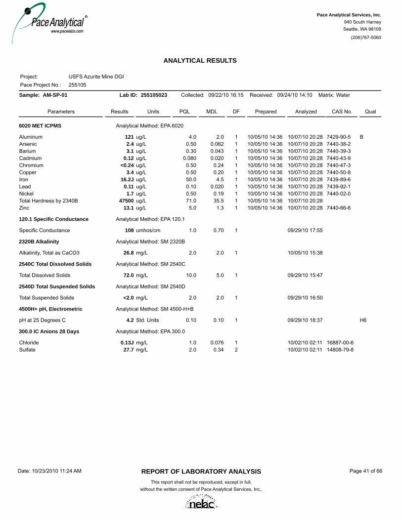
ANALYTICAL RESULTS
Pace Project No.:Project:
255105USFS Azurite Mine DGI
Sample: AM-SP-01 Lab ID: 255105023 Collected: 09/22/10 16:15 Received: 09/24/10 14:10 Matrix: Water
Parameters Results Units DF Prepared Analyzed CAS No. QualMDLPQL
6020 MET ICPMS Analytical Method: EPA 6020
Aluminum 121 ug/L 1 10/07/10 20:28 7429-90-5 B10/05/10 14:364.0 2.0Arsenic 2.4 ug/L 1 10/07/10 20:28 7440-38-210/05/10 14:360.50 0.062Barium 3.1 ug/L 1 10/07/10 20:28 7440-39-310/05/10 14:360.30 0.043Cadmium 0.12 ug/L 1 10/07/10 20:28 7440-43-910/05/10 14:360.080 0.020Chromium <0.24 ug/L 1 10/07/10 20:28 7440-47-310/05/10 14:360.50 0.24Copper 3.4 ug/L 1 10/07/10 20:28 7440-50-810/05/10 14:360.50 0.20Iron 16.2J ug/L 1 10/07/10 20:28 7439-89-610/05/10 14:3650.0 4.5Lead 0.11 ug/L 1 10/07/10 20:28 7439-92-110/05/10 14:360.10 0.020Nickel 1.7 ug/L 1 10/07/10 20:28 7440-02-010/05/10 14:360.50 0.19Total Hardness by 2340B 47500 ug/L 1 10/07/10 20:2810/05/10 14:3671.0 35.5Zinc 13.1 ug/L 1 10/07/10 20:28 7440-66-610/05/10 14:365.0 1.3
120.1 Specific Conductance Analytical Method: EPA 120.1
Specific Conductance 108 umhos/cm 1 09/29/10 17:551.0 0.70
2320B Alkalinity Analytical Method: SM 2320B
Alkalinity, Total as CaCO3 26.8 mg/L 1 10/05/10 15:382.0 2.0
2540C Total Dissolved Solids Analytical Method: SM 2540C
Total Dissolved Solids 72.0 mg/L 1 09/29/10 15:4710.0 5.0
2540D Total Suspended Solids Analytical Method: SM 2540D
Total Suspended Solids <2.0 mg/L 1 09/29/10 16:502.0 2.0
4500H+ pH, Electrometric Analytical Method: SM 4500-H+B
pH at 25 Degrees C 4.2 Std. Units 1 09/29/10 18:37 H60.10 0.10
300.0 IC Anions 28 Days Analytical Method: EPA 300.0
Chloride 0.13J mg/L 1 10/02/10 02:11 16887-00-61.0 0.076Sulfate 27.7 mg/L 2 10/02/10 02:11 14808-79-82.0 0.34
REPORT OF LABORATORY ANALYSISThis report shall not be reproduced, except in full,
without the written consent of Pace Analytical Services, Inc..
Date: 10/23/2010 11:24 AM Page 41 of 66
Pace Analytical Services, Inc.940 South HarneySeattle, WA 98108
(206)767-5060

ANALYTICAL RESULTS
Pace Project No.:Project:
255105USFS Azurite Mine DGI
Sample: MC-SW-07 Lab ID: 255105024 Collected: 09/21/10 11:55 Received: 09/24/10 14:10 Matrix: Water
Parameters Results Units DF Prepared Analyzed CAS No. QualMDLPQL
6020 MET ICPMS Analytical Method: EPA 6020
Aluminum 66.0 ug/L 1 10/07/10 20:32 7429-90-5 B10/05/10 14:364.0 2.0Arsenic 1.1 ug/L 1 10/07/10 20:32 7440-38-210/05/10 14:360.50 0.062Barium 2.6 ug/L 1 10/07/10 20:32 7440-39-310/05/10 14:360.30 0.043Cadmium 0.049J ug/L 1 10/07/10 20:32 7440-43-910/05/10 14:360.080 0.020Chromium 0.32J ug/L 1 10/07/10 20:32 7440-47-310/05/10 14:360.50 0.24Copper 1.5 ug/L 1 10/07/10 20:32 7440-50-810/05/10 14:360.50 0.20Iron 73.4 ug/L 1 10/07/10 20:32 7439-89-610/05/10 14:3650.0 4.5Lead 0.086J ug/L 1 10/07/10 20:32 7439-92-110/05/10 14:360.10 0.020Nickel 0.38J ug/L 1 10/07/10 20:32 7440-02-010/05/10 14:360.50 0.19Zinc 5.2 ug/L 1 10/07/10 20:32 7440-66-610/05/10 14:365.0 1.3
REPORT OF LABORATORY ANALYSISThis report shall not be reproduced, except in full,
without the written consent of Pace Analytical Services, Inc..
Date: 10/23/2010 11:24 AM Page 42 of 66
Pace Analytical Services, Inc.940 South HarneySeattle, WA 98108
(206)767-5060

ANALYTICAL RESULTS
Pace Project No.:Project:
255105USFS Azurite Mine DGI
Sample: MC-SW-08 Lab ID: 255105025 Collected: 09/21/10 18:40 Received: 09/24/10 14:10 Matrix: Water
Parameters Results Units DF Prepared Analyzed CAS No. QualMDLPQL
6020 MET ICPMS Analytical Method: EPA 6020
Aluminum 3.3J ug/L 1 10/07/10 07:17 7429-90-510/05/10 14:364.0 2.0Arsenic <0.062 ug/L 1 10/07/10 07:17 7440-38-210/05/10 14:360.50 0.062Barium 0.18J ug/L 1 10/07/10 07:17 7440-39-310/05/10 14:360.30 0.043Cadmium <0.020 ug/L 1 10/07/10 07:17 7440-43-910/05/10 14:360.080 0.020Chromium <0.24 ug/L 1 10/07/10 07:17 7440-47-310/05/10 14:360.50 0.24Copper <0.20 ug/L 1 10/07/10 07:17 7440-50-810/05/10 14:360.50 0.20Iron <4.5 ug/L 1 10/07/10 07:17 7439-89-610/05/10 14:3650.0 4.5Lead <0.020 ug/L 1 10/07/10 07:17 7439-92-110/05/10 14:360.10 0.020Nickel <0.19 ug/L 1 10/07/10 07:17 7440-02-010/05/10 14:360.50 0.19Zinc 3.2J ug/L 1 10/07/10 07:17 7440-66-610/05/10 14:365.0 1.3
REPORT OF LABORATORY ANALYSISThis report shall not be reproduced, except in full,
without the written consent of Pace Analytical Services, Inc..
Date: 10/23/2010 11:24 AM Page 43 of 66
Pace Analytical Services, Inc.940 South HarneySeattle, WA 98108
(206)767-5060

ANALYTICAL RESULTS
Pace Project No.:Project:
255105USFS Azurite Mine DGI
Sample: BKG-06 Lab ID: 255105026 Collected: 09/22/10 13:00 Received: 09/24/10 14:10 Matrix: SolidResults reported on a "dry-weight" basis
Parameters Results Units DF Prepared Analyzed CAS No. QualMDLPQL
6020 MET ICPMS Analytical Method: EPA 6020
Aluminum 12600 mg/kg 50 10/07/10 02:35 7429-90-510/04/10 16:269.5 4.7Arsenic 31.3 mg/kg 50 10/07/10 02:35 7440-38-210/04/10 16:261.2 0.24Barium 29.6 mg/kg 50 10/07/10 02:35 7440-39-310/04/10 16:260.71 0.047Cadmium 0.15J mg/kg 50 10/07/10 02:35 7440-43-910/04/10 16:260.19 0.047Chromium 53.0 mg/kg 50 10/07/10 02:35 7440-47-310/04/10 16:261.2 0.33Copper 81.1 mg/kg 50 10/07/10 02:35 7440-50-810/04/10 16:261.2 0.33Iron 44100 mg/kg 50 10/07/10 02:35 7439-89-610/04/10 16:26118 25.7Lead 4.4 mg/kg 50 10/07/10 02:35 7439-92-110/04/10 16:261.2 0.095Nickel 33.7 mg/kg 50 10/07/10 02:35 7440-02-010/04/10 16:261.2 0.24Zinc 61.4 mg/kg 50 10/07/10 02:35 7440-66-610/04/10 16:2611.8 3.2
USDA 21A pH Analytical Method: USDA 21A
pH, Saturated Paste 7.5 Std. Units 1 10/04/10 14:300.10
Percent Moisture Analytical Method: ASTM D2974-87
Percent Moisture 8.8 % 1 09/30/10 14:080.10 0.10
REPORT OF LABORATORY ANALYSISThis report shall not be reproduced, except in full,
without the written consent of Pace Analytical Services, Inc..
Date: 10/23/2010 11:24 AM Page 44 of 66
Pace Analytical Services, Inc.940 South HarneySeattle, WA 98108
(206)767-5060

ANALYTICAL RESULTS
Pace Project No.:Project:
255105USFS Azurite Mine DGI
Sample: BKG-07 Lab ID: 255105027 Collected: 09/22/10 13:20 Received: 09/24/10 14:10 Matrix: SolidResults reported on a "dry-weight" basis
Parameters Results Units DF Prepared Analyzed CAS No. QualMDLPQL
6020 MET ICPMS Analytical Method: EPA 6020
Aluminum 57500 mg/kg 50 10/07/10 03:20 7429-90-510/04/10 16:2612.1 6.1Arsenic 11.6 mg/kg 50 10/07/10 03:20 7440-38-210/04/10 16:261.5 0.30Barium 160 mg/kg 50 10/07/10 03:20 7440-39-310/04/10 16:260.91 0.061Cadmium 0.14J mg/kg 50 10/07/10 03:20 7440-43-910/04/10 16:260.24 0.061Chromium 51.7 mg/kg 50 10/07/10 03:20 7440-47-310/04/10 16:261.5 0.43Copper 93.0 mg/kg 50 10/07/10 03:20 7440-50-810/04/10 16:261.5 0.43Iron 43300 mg/kg 50 10/07/10 03:20 7439-89-610/04/10 16:26152 33.0Lead 5.1 mg/kg 50 10/07/10 03:20 7439-92-110/04/10 16:261.5 0.12Nickel 27.1 mg/kg 50 10/07/10 03:20 7440-02-010/04/10 16:261.5 0.30Zinc 63.5 mg/kg 50 10/07/10 03:20 7440-66-610/04/10 16:2615.2 4.1
USDA 21A pH Analytical Method: USDA 21A
pH, Saturated Paste 5.3 Std. Units 1 10/04/10 14:300.10
Percent Moisture Analytical Method: ASTM D2974-87
Percent Moisture 40.8 % 1 09/30/10 14:090.10 0.10
REPORT OF LABORATORY ANALYSISThis report shall not be reproduced, except in full,
without the written consent of Pace Analytical Services, Inc..
Date: 10/23/2010 11:24 AM Page 45 of 66
Pace Analytical Services, Inc.940 South HarneySeattle, WA 98108
(206)767-5060

ANALYTICAL RESULTS
Pace Project No.:Project:
255105USFS Azurite Mine DGI
Sample: BKG-08 Lab ID: 255105028 Collected: 09/22/10 14:35 Received: 09/24/10 14:10 Matrix: SolidResults reported on a "dry-weight" basis
Parameters Results Units DF Prepared Analyzed CAS No. QualMDLPQL
6020 MET ICPMS Analytical Method: EPA 6020
Aluminum 27100 mg/kg 50 10/07/10 03:25 7429-90-510/04/10 16:2612.7 6.4Arsenic 122 mg/kg 50 10/07/10 03:25 7440-38-210/04/10 16:261.6 0.32Barium 25.9 mg/kg 50 10/07/10 03:25 7440-39-310/04/10 16:260.95 0.064Cadmium 2.2 mg/kg 50 10/07/10 03:25 7440-43-910/04/10 16:260.25 0.064Chromium 60.0 mg/kg 50 10/07/10 03:25 7440-47-310/04/10 16:261.6 0.44Copper 154 mg/kg 50 10/07/10 03:25 7440-50-810/04/10 16:261.6 0.44Iron 87600 mg/kg 50 10/07/10 03:25 7439-89-610/04/10 16:26159 34.5Lead 32.1 mg/kg 50 10/07/10 03:25 7439-92-110/04/10 16:261.6 0.13Nickel 21.5 mg/kg 50 10/07/10 03:25 7440-02-010/04/10 16:261.6 0.32Zinc 676 mg/kg 50 10/07/10 03:25 7440-66-610/04/10 16:2615.9 4.3
USDA 21A pH Analytical Method: USDA 21A
pH, Saturated Paste 5.0 Std. Units 1 10/04/10 14:300.10
Percent Moisture Analytical Method: ASTM D2974-87
Percent Moisture 38.1 % 1 09/30/10 14:110.10 0.10
REPORT OF LABORATORY ANALYSISThis report shall not be reproduced, except in full,
without the written consent of Pace Analytical Services, Inc..
Date: 10/23/2010 11:24 AM Page 46 of 66
Pace Analytical Services, Inc.940 South HarneySeattle, WA 98108
(206)767-5060

ANALYTICAL RESULTS
Pace Project No.:Project:
255105USFS Azurite Mine DGI
Sample: BKG-09 Lab ID: 255105029 Collected: 09/22/10 14:00 Received: 09/24/10 14:10 Matrix: SolidResults reported on a "dry-weight" basis
Parameters Results Units DF Prepared Analyzed CAS No. QualMDLPQL
6020 MET ICPMS Analytical Method: EPA 6020
Aluminum 41800 mg/kg 50 10/07/10 03:29 7429-90-510/04/10 16:269.2 4.6Arsenic 87.2 mg/kg 50 10/07/10 03:29 7440-38-210/04/10 16:261.2 0.23Barium 106 mg/kg 50 10/07/10 03:29 7440-39-310/04/10 16:260.69 0.046Cadmium 0.99 mg/kg 50 10/07/10 03:29 7440-43-910/04/10 16:260.18 0.046Chromium 154 mg/kg 50 10/07/10 03:29 7440-47-310/04/10 16:261.2 0.32Copper 341 mg/kg 50 10/07/10 03:29 7440-50-810/04/10 16:261.2 0.32Iron 55400 mg/kg 50 10/07/10 03:29 7439-89-610/04/10 16:26115 25.0Lead 17.1 mg/kg 50 10/07/10 03:29 7439-92-110/04/10 16:261.2 0.092Nickel 76.2 mg/kg 50 10/07/10 03:29 7440-02-010/04/10 16:261.2 0.23Zinc 251 mg/kg 50 10/07/10 03:29 7440-66-610/04/10 16:2611.5 3.1
USDA 21A pH Analytical Method: USDA 21A
pH, Saturated Paste 5.2 Std. Units 1 10/04/10 14:300.10
Percent Moisture Analytical Method: ASTM D2974-87
Percent Moisture 20.8 % 1 10/04/10 13:310.10 0.10
REPORT OF LABORATORY ANALYSISThis report shall not be reproduced, except in full,
without the written consent of Pace Analytical Services, Inc..
Date: 10/23/2010 11:24 AM Page 47 of 66
Pace Analytical Services, Inc.940 South HarneySeattle, WA 98108
(206)767-5060

QUALITY CONTROL DATA
Pace Project No.:Project:
255105USFS Azurite Mine DGI
QC Batch:QC Batch Method:
Analysis Method:Analysis Description:
MPRP/1805EPA 3050
EPA 60106010 MET
Associated Lab Samples: 255105011, 255105012, 255105013, 255105014, 255105015, 255105016, 255105017, 255105018, 255105019,255105020
Parameter UnitsBlankResult
ReportingLimit Qualifiers
METHOD BLANK: 42994
Associated Lab Samples: 255105011, 255105012, 255105013, 255105014, 255105015, 255105016, 255105017, 255105018, 255105019,255105020
Matrix: Solid
Analyzed
Aluminum mg/kg <1.1 50.0 10/04/10 12:09Arsenic mg/kg <0.17 2.0 10/04/10 12:09Barium mg/kg 0.024J 20.0 10/04/10 12:09Cadmium mg/kg <0.010 1.0 10/04/10 12:09Chromium mg/kg <0.050 1.0 10/04/10 12:09Copper mg/kg <0.12 2.5 10/04/10 12:09Iron mg/kg 0.89J 20.0 10/04/10 12:09Nickel mg/kg <0.020 4.0 10/04/10 12:09
Parameter UnitsLCS
Result% RecLimits Qualifiers% RecConc.
42995LABORATORY CONTROL SAMPLE:LCSSpike
Aluminum mg/kg 471500 94 80-120Arsenic mg/kg 24.125 97 80-120Barium mg/kg 22.925 92 80-120Cadmium mg/kg 25.025 100 80-120Chromium mg/kg 24.425 97 80-120Copper mg/kg 24.825 99 80-120Iron mg/kg 458500 92 80-120Nickel mg/kg 25.925 104 80-120
Parameter UnitsMS
Result% RecLimits Qual% RecConc.
42996MATRIX SPIKE & MATRIX SPIKE DUPLICATE:
MSSpikeResult
255105011
42997
MSDResult
MSD% Rec RPD RPD
MaxMSDMSSpikeConc.
Aluminum mg/kg M1516 -152 75-125-116 2 205219870 9080 9260Arsenic mg/kg M1,R125.8 118 75-125202 32 2026.128.1 58.5 80.7Barium mg/kg M1,R125.8 130 75-12569 30 2026.126.0 59.5 44.0Cadmium mg/kg 25.8 102 75-12598 3 2026.1<0.11 26.4 25.6Chromium mg/kg M125.8 63 75-12572 7 2026.119.2 35.4 38.1Copper mg/kg M1,R125.8 -72 75-125139 62 2026.179.4 60.8 116Iron mg/kg M1,R1516 -4810 75-125-3070 27 2052152800 28000 36800Nickel mg/kg M125.8 -4 75-12564 2026.139.0J 38.0J 55.6
REPORT OF LABORATORY ANALYSISThis report shall not be reproduced, except in full,
without the written consent of Pace Analytical Services, Inc..
Date: 10/23/2010 11:24 AM Page 48 of 66
Pace Analytical Services, Inc.940 South HarneySeattle, WA 98108
(206)767-5060

QUALITY CONTROL DATA
Pace Project No.:Project:
255105USFS Azurite Mine DGI
QC Batch:QC Batch Method:
Analysis Method:Analysis Description:
ICPM/22644EPA 6020
EPA 60206020 MET
Associated Lab Samples: 255105011, 255105012, 255105013, 255105014, 255105015, 255105016, 255105017, 255105018, 255105019,255105020, 255105026, 255105027, 255105028, 255105029
Parameter UnitsBlankResult
ReportingLimit Qualifiers
METHOD BLANK: 863609
Associated Lab Samples: 255105011, 255105012, 255105013, 255105014, 255105015, 255105016, 255105017, 255105018, 255105019,255105020, 255105026, 255105027, 255105028, 255105029
Matrix: Solid
Analyzed
Aluminum mg/kg <1.4 2.7 10/07/10 00:26Arsenic mg/kg <0.068 0.34 10/07/10 00:26Barium mg/kg 0.019J 0.20 10/07/10 00:26Cadmium mg/kg <0.014 0.054 10/07/10 00:26Chromium mg/kg <0.095 0.34 10/07/10 00:26Copper mg/kg <0.095 0.34 10/07/10 00:26Iron mg/kg <7.3 33.8 10/07/10 00:26Lead mg/kg <0.027 0.34 10/07/10 00:26Nickel mg/kg <0.068 0.34 10/07/10 00:26Zinc mg/kg <0.92 3.4 10/07/10 00:26
Parameter UnitsLCS
Result% RecLimits Qualifiers% RecConc.
863610LABORATORY CONTROL SAMPLE:LCSSpike
Aluminum mg/kg 16.516 103 75-125Arsenic mg/kg 15.516 97 75-125Barium mg/kg 15.116 94 75-125Cadmium mg/kg 15.316 96 75-125Chromium mg/kg 15.616 98 75-125Copper mg/kg 15.616 97 75-125Iron mg/kg 193200 97 75-125Lead mg/kg 16.016 100 75-125Nickel mg/kg 16.116 101 75-125Zinc mg/kg 15.316 96 75-125
Parameter UnitsMS
Result% RecLimits Qual% RecConc.
863611MATRIX SPIKE & MATRIX SPIKE DUPLICATE:
MSSpikeResult
255105011
863612
MSDResult
MSD% Rec RPD RPD
MaxMSDMSSpikeConc.
Aluminum mg/kg 19 -12300 75-125-4120 30 2016.2 4810 6470Arsenic mg/kg 19 143 75-125152 8 2016.2 35.5 32.9Barium mg/kg 19 98 75-125103 6 2016.2 31.7 29.7Cadmium mg/kg 19 110 75-125107 18 2016.2 20.8 17.4Chromium mg/kg 19 217 75-12599 68 2016.2 49.4 24.3Copper mg/kg 19 206 75-125242 .2 2016.2 53.9 54.0Iron mg/kg 237 -248 75-1252850 37 20202 14100 20500Lead mg/kg 19 122 75-125118 18 2016.20.70 23.8 19.9Nickel mg/kg 19 153 75-125118 30 2016.2 38.0 28.1
REPORT OF LABORATORY ANALYSISThis report shall not be reproduced, except in full,
without the written consent of Pace Analytical Services, Inc..
Date: 10/23/2010 11:24 AM Page 49 of 66
Pace Analytical Services, Inc.940 South HarneySeattle, WA 98108
(206)767-5060
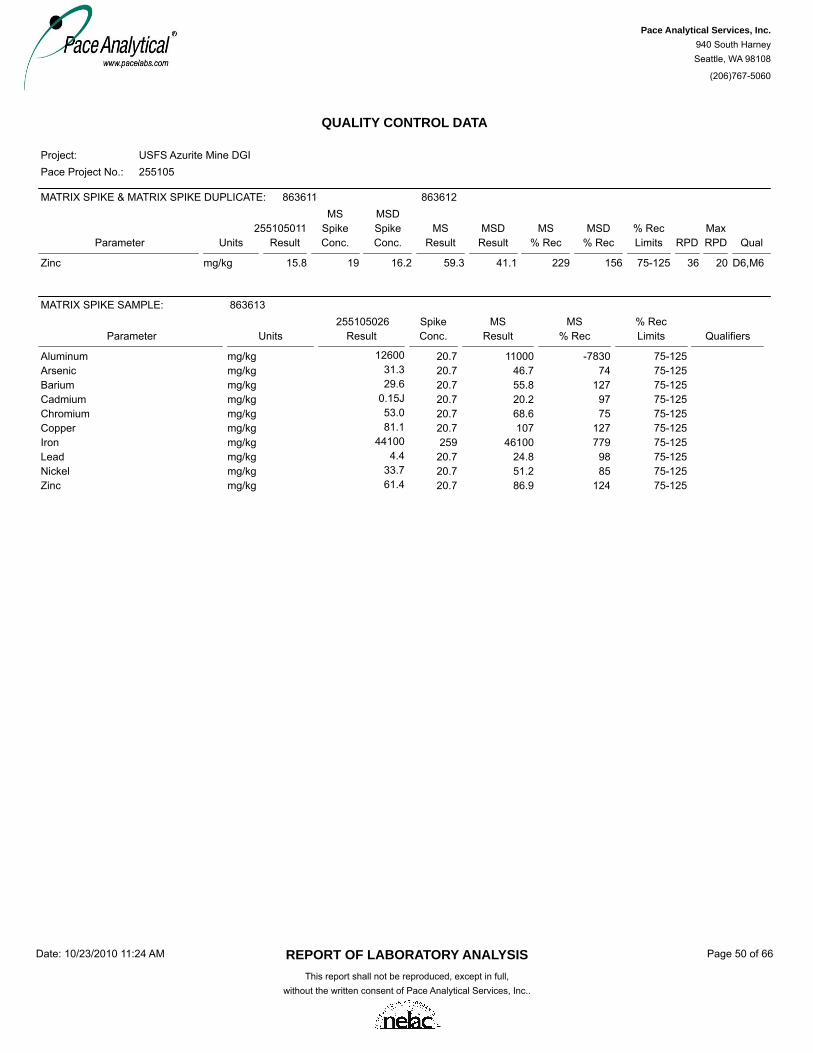
QUALITY CONTROL DATA
Pace Project No.:Project:
255105USFS Azurite Mine DGI
Parameter UnitsMS
Result% RecLimits Qual% RecConc.
863611MATRIX SPIKE & MATRIX SPIKE DUPLICATE:
MSSpikeResult
255105011
863612
MSDResult
MSD% Rec RPD RPD
MaxMSDMSSpikeConc.
Zinc mg/kg D6,M619 229 75-125156 36 2016.215.8 59.3 41.1
Parameter UnitsMS
Result% RecLimits Qualifiers% RecConc.
863613MATRIX SPIKE SAMPLE:MSSpike
Result255105026
Aluminum mg/kg 1100020.7 -7830 75-12512600Arsenic mg/kg 46.720.7 74 75-12531.3Barium mg/kg 55.820.7 127 75-12529.6Cadmium mg/kg 20.220.7 97 75-1250.15JChromium mg/kg 68.620.7 75 75-12553.0Copper mg/kg 10720.7 127 75-12581.1Iron mg/kg 46100259 779 75-12544100Lead mg/kg 24.820.7 98 75-1254.4Nickel mg/kg 51.220.7 85 75-12533.7Zinc mg/kg 86.920.7 124 75-12561.4
REPORT OF LABORATORY ANALYSISThis report shall not be reproduced, except in full,
without the written consent of Pace Analytical Services, Inc..
Date: 10/23/2010 11:24 AM Page 50 of 66
Pace Analytical Services, Inc.940 South HarneySeattle, WA 98108
(206)767-5060

QUALITY CONTROL DATA
Pace Project No.:Project:
255105USFS Azurite Mine DGI
QC Batch:QC Batch Method:
Analysis Method:Analysis Description:
ICPM/22647EPA 6020
EPA 60206020 MET
Associated Lab Samples: 255105001, 255105002, 255105003, 255105004, 255105005, 255105006, 255105007, 255105008, 255105009,255105010, 255105021, 255105022
Parameter UnitsBlankResult
ReportingLimit Qualifiers
METHOD BLANK: 863624
Associated Lab Samples: 255105001, 255105002, 255105003, 255105004, 255105005, 255105006, 255105007, 255105008, 255105009,255105010, 255105021, 255105022, 255105023, 255105024, 255105025
Matrix: Water
Analyzed
Aluminum ug/L 2.3J 4.0 10/07/10 04:36Arsenic ug/L <0.062 0.50 10/07/10 04:36Barium ug/L <0.043 0.30 10/07/10 04:36Cadmium ug/L <0.020 0.080 10/07/10 04:36Chromium ug/L <0.24 0.50 10/07/10 04:36Copper ug/L <0.20 0.50 10/07/10 04:36Iron ug/L <4.5 50.0 10/07/10 04:36Lead ug/L <0.020 0.10 10/07/10 04:36Nickel ug/L <0.19 0.50 10/07/10 04:36Total Hardness by 2340B ug/L <35.5 71.0 10/07/10 04:36Zinc ug/L <1.3 5.0 10/07/10 04:36
Parameter UnitsLCS
Result% RecLimits Qualifiers% RecConc.
863625LABORATORY CONTROL SAMPLE:LCSSpike
Aluminum ug/L 81.780 102 80-120Arsenic ug/L 81.680 102 80-120Barium ug/L 81.080 101 80-120Cadmium ug/L 83.280 104 80-120Chromium ug/L 83.880 105 80-120Copper ug/L 80.480 101 80-120Iron ug/L 10201000 102 80-120Lead ug/L 85.180 106 80-120Nickel ug/L 83.980 105 80-120Total Hardness by 2340B ug/L 6700Zinc ug/L 83.380 104 80-120
Parameter UnitsMS
Result% RecLimits Qual% RecConc.
863626MATRIX SPIKE & MATRIX SPIKE DUPLICATE:
MSSpikeResult
255105001
863627
MSDResult
MSD% Rec RPD RPD
MaxMSDMSSpikeConc.
Aluminum ug/L 80 103 75-125102 .6 20806.7 88.8 88.3Arsenic ug/L 80 104 75-125101 3 20800.60 84.0 81.8Barium ug/L 80 101 75-125102 .3 20801.7 82.9 83.2Cadmium ug/L 80 105 75-125104 .1 2080<0.020 83.7 83.6Chromium ug/L 80 107 75-125105 2 2080<0.24 85.9 84.0Copper ug/L 80 102 75-125108 5 2080<0.20 81.8 86.0Iron ug/L 1000 106 75-125104 2 201000<4.5 1060 1040
REPORT OF LABORATORY ANALYSISThis report shall not be reproduced, except in full,
without the written consent of Pace Analytical Services, Inc..
Date: 10/23/2010 11:24 AM Page 51 of 66
Pace Analytical Services, Inc.940 South HarneySeattle, WA 98108
(206)767-5060

QUALITY CONTROL DATA
Pace Project No.:Project:
255105USFS Azurite Mine DGI
Parameter UnitsMS
Result% RecLimits Qual% RecConc.
863626MATRIX SPIKE & MATRIX SPIKE DUPLICATE:
MSSpikeResult
255105001
863627
MSDResult
MSD% Rec RPD RPD
MaxMSDMSSpikeConc.
Lead ug/L 80 108 75-125107 .4 2080<0.020 86.0 85.6Nickel ug/L 80 106 75-125107 .5 2080<0.19 85.0 85.5Total Hardness by 2340B ug/L 2 2011800 19000 18500Zinc ug/L 80 101 75-125105 4 20802.4J 83.4 86.6
Parameter UnitsMS
Result% RecLimits Qualifiers% RecConc.
863628MATRIX SPIKE SAMPLE:MSSpike
Result255105021
Aluminum ug/L 12880 108 75-12541.6Arsenic ug/L 11280 109 75-12524.8Barium ug/L 86.880 107 75-1251.3Cadmium ug/L 86.880 108 75-1250.092Chromium ug/L 86.680 108 75-125<0.24Copper ug/L 89.680 109 75-1252.0Iron ug/L 12101000 107 75-125145Lead ug/L 85.680 107 75-1250.033JNickel ug/L 86.880 108 75-1250.66Total Hardness by 2340B ug/L 6580055800Zinc ug/L 97.880 108 75-12511.5
REPORT OF LABORATORY ANALYSISThis report shall not be reproduced, except in full,
without the written consent of Pace Analytical Services, Inc..
Date: 10/23/2010 11:24 AM Page 52 of 66
Pace Analytical Services, Inc.940 South HarneySeattle, WA 98108
(206)767-5060

QUALITY CONTROL DATA
Pace Project No.:Project:
255105USFS Azurite Mine DGI
QC Batch:QC Batch Method:
Analysis Method:Analysis Description:
MT/5015USDA 21A
USDA 21AUSDA 21A pH saturated paste
Associated Lab Samples: 255105026, 255105027, 255105028, 255105029
Parameter UnitsLCS
Result% RecLimits Qualifiers% RecConc.
864940LABORATORY CONTROL SAMPLE:LCSSpike
pH, Saturated Paste Std. Units 7.07.3 95 91-109
Parameter UnitsDup
ResultMaxRPD QualifiersRPDResult
10139415001864941SAMPLE DUPLICATE:
pH, Saturated Paste Std. Units 7.8 .1 207.8
REPORT OF LABORATORY ANALYSISThis report shall not be reproduced, except in full,
without the written consent of Pace Analytical Services, Inc..
Date: 10/23/2010 11:24 AM Page 53 of 66
Pace Analytical Services, Inc.940 South HarneySeattle, WA 98108
(206)767-5060
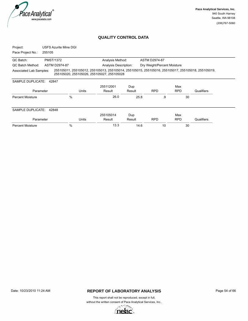
QUALITY CONTROL DATA
Pace Project No.:Project:
255105USFS Azurite Mine DGI
QC Batch:QC Batch Method:
Analysis Method:Analysis Description:
PMST/1372ASTM D2974-87
ASTM D2974-87Dry Weight/Percent Moisture
Associated Lab Samples: 255105011, 255105012, 255105013, 255105014, 255105015, 255105016, 255105017, 255105018, 255105019,255105020, 255105026, 255105027, 255105028
Parameter UnitsDup
ResultMaxRPD QualifiersRPDResult
25511200142847SAMPLE DUPLICATE:
Percent Moisture % 25.8 .9 3026.0
Parameter UnitsDup
ResultMaxRPD QualifiersRPDResult
25510501442848SAMPLE DUPLICATE:
Percent Moisture % 14.6 10 3013.3
REPORT OF LABORATORY ANALYSISThis report shall not be reproduced, except in full,
without the written consent of Pace Analytical Services, Inc..
Date: 10/23/2010 11:24 AM Page 54 of 66
Pace Analytical Services, Inc.940 South HarneySeattle, WA 98108
(206)767-5060

QUALITY CONTROL DATA
Pace Project No.:Project:
255105USFS Azurite Mine DGI
QC Batch:QC Batch Method:
Analysis Method:Analysis Description:
PMST/1374ASTM D2974-87
ASTM D2974-87Dry Weight/Percent Moisture
Associated Lab Samples: 255105029
Parameter UnitsDup
ResultMaxRPD QualifiersRPDResult
25509502743340SAMPLE DUPLICATE:
Percent Moisture % 11.3 3 3011.0
Parameter UnitsDup
ResultMaxRPD QualifiersRPDResult
25516700243341SAMPLE DUPLICATE:
Percent Moisture % 60.8 5 3064.0
REPORT OF LABORATORY ANALYSISThis report shall not be reproduced, except in full,
without the written consent of Pace Analytical Services, Inc..
Date: 10/23/2010 11:24 AM Page 55 of 66
Pace Analytical Services, Inc.940 South HarneySeattle, WA 98108
(206)767-5060

QUALITY CONTROL DATA
Pace Project No.:Project:
255105USFS Azurite Mine DGI
QC Batch:QC Batch Method:
Analysis Method:Analysis Description:
WET/2288EPA 120.1
EPA 120.1120.1 Specific Conductance
Associated Lab Samples: 255105001, 255105002, 255105003, 255105004, 255105005, 255105006, 255105007, 255105008, 255105009,255105010, 255105021, 255105022, 255105023
Parameter UnitsBlankResult
ReportingLimit Qualifiers
METHOD BLANK: 42594
Associated Lab Samples: 255105001, 255105002, 255105003, 255105004, 255105005, 255105006, 255105007, 255105008, 255105009,255105010, 255105021, 255105022, 255105023
Matrix: Water
Analyzed
Specific Conductance umhos/cm <0.70 1.0 09/29/10 17:55
Parameter UnitsLCS
Result% RecLimits Qualifiers% RecConc.
42595LABORATORY CONTROL SAMPLE:LCSSpike
Specific Conductance umhos/cm 434445 98 90-110
Parameter UnitsDup
ResultMaxRPD QualifiersRPDResult
25500400142596SAMPLE DUPLICATE:
Specific Conductance umhos/cm <0.70 10ND
Parameter UnitsDup
ResultMaxRPD QualifiersRPDResult
25510500842597SAMPLE DUPLICATE:
Specific Conductance umhos/cm 72.4 3 1074.8
REPORT OF LABORATORY ANALYSISThis report shall not be reproduced, except in full,
without the written consent of Pace Analytical Services, Inc..
Date: 10/23/2010 11:24 AM Page 56 of 66
Pace Analytical Services, Inc.940 South HarneySeattle, WA 98108
(206)767-5060

QUALITY CONTROL DATA
Pace Project No.:Project:
255105USFS Azurite Mine DGI
QC Batch:QC Batch Method:
Analysis Method:Analysis Description:
WET/2304SM 2320B
SM 2320B2320B Alkalinity
Associated Lab Samples: 255105021, 255105022, 255105023
Parameter UnitsBlankResult
ReportingLimit Qualifiers
METHOD BLANK: 43202
Associated Lab Samples: 255105021, 255105022, 255105023
Matrix: Water
Analyzed
Alkalinity, Total as CaCO3 mg/L <2.0 2.0 10/05/10 15:38
Parameter UnitsLCS
Result% RecLimits Qualifiers% RecConc.
43203LABORATORY CONTROL SAMPLE:LCSSpike
Alkalinity, Total as CaCO3 mg/L 96.3100 96 90-110
Parameter UnitsDup
ResultMaxRPD QualifiersRPDResult
25507600443204SAMPLE DUPLICATE:
Alkalinity, Total as CaCO3 mg/L 349 3 10359
REPORT OF LABORATORY ANALYSISThis report shall not be reproduced, except in full,
without the written consent of Pace Analytical Services, Inc..
Date: 10/23/2010 11:24 AM Page 57 of 66
Pace Analytical Services, Inc.940 South HarneySeattle, WA 98108
(206)767-5060

QUALITY CONTROL DATA
Pace Project No.:Project:
255105USFS Azurite Mine DGI
QC Batch:QC Batch Method:
Analysis Method:Analysis Description:
WET/2286SM 2540C
SM 2540C2540C Total Dissolved Solids
Associated Lab Samples: 255105001, 255105002, 255105003, 255105004, 255105005, 255105006, 255105007, 255105008, 255105009,255105010, 255105021, 255105022, 255105023
Parameter UnitsBlankResult
ReportingLimit Qualifiers
METHOD BLANK: 42531
Associated Lab Samples: 255105001, 255105002, 255105003, 255105004, 255105005, 255105006, 255105007, 255105008, 255105009,255105010, 255105021, 255105022, 255105023
Matrix: Water
Analyzed
Total Dissolved Solids mg/L <5.0 10.0 09/29/10 15:30
Parameter UnitsLCS
Result% RecLimits Qualifiers% RecConc.
42532LABORATORY CONTROL SAMPLE:LCSSpike
Total Dissolved Solids mg/L 320300 107 80-120
Parameter UnitsDup
ResultMaxRPD QualifiersRPDResult
25510500842533SAMPLE DUPLICATE:
Total Dissolved Solids mg/L 48.0 6 2051.0
Parameter UnitsDup
ResultMaxRPD QualifiersRPDResult
25510502142534SAMPLE DUPLICATE:
Total Dissolved Solids mg/L 73.0 3 2075.0
REPORT OF LABORATORY ANALYSISThis report shall not be reproduced, except in full,
without the written consent of Pace Analytical Services, Inc..
Date: 10/23/2010 11:24 AM Page 58 of 66
Pace Analytical Services, Inc.940 South HarneySeattle, WA 98108
(206)767-5060

QUALITY CONTROL DATA
Pace Project No.:Project:
255105USFS Azurite Mine DGI
QC Batch:QC Batch Method:
Analysis Method:Analysis Description:
WET/2287SM 2540D
SM 2540D2540D Total Suspended Solids
Associated Lab Samples: 255105001, 255105002, 255105003, 255105004, 255105005, 255105006, 255105007, 255105008, 255105009,255105010, 255105021, 255105022, 255105023
Parameter UnitsBlankResult
ReportingLimit Qualifiers
METHOD BLANK: 42535
Associated Lab Samples: 255105001, 255105002, 255105003, 255105004, 255105005, 255105006, 255105007, 255105008, 255105009,255105010, 255105021, 255105022, 255105023
Matrix: Water
Analyzed
Total Suspended Solids mg/L <2.0 2.0 09/29/10 16:50
Parameter UnitsDup
ResultMaxRPD QualifiersRPDResult
25510500842536SAMPLE DUPLICATE:
Total Suspended Solids mg/L 4.0 R329 203.0
Parameter UnitsDup
ResultMaxRPD QualifiersRPDResult
25510502142537SAMPLE DUPLICATE:
Total Suspended Solids mg/L 11.0 0 2011.0
REPORT OF LABORATORY ANALYSISThis report shall not be reproduced, except in full,
without the written consent of Pace Analytical Services, Inc..
Date: 10/23/2010 11:24 AM Page 59 of 66
Pace Analytical Services, Inc.940 South HarneySeattle, WA 98108
(206)767-5060

QUALITY CONTROL DATA
Pace Project No.:Project:
255105USFS Azurite Mine DGI
QC Batch:QC Batch Method:
Analysis Method:Analysis Description:
WET/2278SM 4500-H+B
SM 4500-H+B4500H+B pH
Associated Lab Samples: 255105001, 255105002, 255105003, 255105004, 255105005, 255105006, 255105007, 255105008, 255105009,255105010
Parameter UnitsDup
ResultMaxRPD QualifiersRPDResult
25510501042314SAMPLE DUPLICATE:
pH at 25 Degrees C Std. Units 7.9 H6.1 107.9
Parameter UnitsDup
ResultMaxRPD QualifiersRPDResult
25509200142315SAMPLE DUPLICATE:
pH at 25 Degrees C Std. Units 7.7 H6.4 107.7
REPORT OF LABORATORY ANALYSISThis report shall not be reproduced, except in full,
without the written consent of Pace Analytical Services, Inc..
Date: 10/23/2010 11:24 AM Page 60 of 66
Pace Analytical Services, Inc.940 South HarneySeattle, WA 98108
(206)767-5060

QUALITY CONTROL DATA
Pace Project No.:Project:
255105USFS Azurite Mine DGI
QC Batch:QC Batch Method:
Analysis Method:Analysis Description:
WET/2285SM 4500-H+B
SM 4500-H+B4500H+B pH
Associated Lab Samples: 255105021, 255105022, 255105023
Parameter UnitsDup
ResultMaxRPD QualifiersRPDResult
25510502142529SAMPLE DUPLICATE:
pH at 25 Degrees C Std. Units 7.4 H6.3 107.4
REPORT OF LABORATORY ANALYSISThis report shall not be reproduced, except in full,
without the written consent of Pace Analytical Services, Inc..
Date: 10/23/2010 11:24 AM Page 61 of 66
Pace Analytical Services, Inc.940 South HarneySeattle, WA 98108
(206)767-5060

QUALITY CONTROL DATA
Pace Project No.:Project:
255105USFS Azurite Mine DGI
QC Batch:QC Batch Method:
Analysis Method:Analysis Description:
WETA/1715EPA 300.0
EPA 300.0300.0 IC Anions
Associated Lab Samples: 255105021, 255105022, 255105023
Parameter UnitsBlankResult
ReportingLimit Qualifiers
METHOD BLANK: 42914
Associated Lab Samples: 255105021, 255105022, 255105023
Matrix: Water
Analyzed
Chloride mg/L <0.076 1.0 10/01/10 16:00Sulfate mg/L <0.17 1.0 10/01/10 16:00
Parameter UnitsLCS
Result% RecLimits Qualifiers% RecConc.
42915LABORATORY CONTROL SAMPLE:LCSSpike
Chloride mg/L 5.35 105 90-110Sulfate mg/L 16.115 107 90-110
Parameter UnitsMS
Result% RecLimits Qual% RecConc.
42916MATRIX SPIKE & MATRIX SPIKE DUPLICATE:
MSSpikeResult
255076002
42917
MSDResult
MSD% Rec RPD RPD
MaxMSDMSSpikeConc.
Chloride mg/L M1250 113 90-11099 5 11250434 717 681Sulfate mg/L E,M1750 116 90-110105 5 10750920 1790 1710
REPORT OF LABORATORY ANALYSISThis report shall not be reproduced, except in full,
without the written consent of Pace Analytical Services, Inc..
Date: 10/23/2010 11:24 AM Page 62 of 66
Pace Analytical Services, Inc.940 South HarneySeattle, WA 98108
(206)767-5060

QUALIFIERS
Pace Project No.:Project:
255105USFS Azurite Mine DGI
DEFINITIONS
DF - Dilution Factor, if reported, represents the factor applied to the reported data due to changes in sample preparation, dilution ofthe sample aliquot, or moisture content.ND - Not Detected at or above adjusted reporting limit.J - Estimated concentration above the adjusted method detection limit and below the adjusted reporting limit.MDL - Adjusted Method Detection Limit.S - Surrogate1,2-Diphenylhydrazine (8270 listed analyte) decomposes to Azobenzene.Consistent with EPA guidelines, unrounded data are displayed and have been used to calculate % recovery and RPD values.LCS(D) - Laboratory Control Sample (Duplicate)MS(D) - Matrix Spike (Duplicate)DUP - Sample DuplicateRPD - Relative Percent DifferenceN-Nitrosodiphenylamine decomposes and cannot be separated from Diphenylamine using Method 8270. The result reported foreach analyte is a combined concentration.Pace Analytical is NELAP accredited. Contact your Pace PM for the current list of accredited analytes.
LABORATORIES
Pace Analytical Services - MinneapolisPASI-MPace Analytical Services - SeattlePASI-S
ANALYTE QUALIFIERS
Analyte was detected in the associated method blank.BThe relative percent difference (RPD) between the sample and sample duplicate exceeded laboratory control limits.D6Analyte concentration exceeded the calibration range. The reported result is estimated.EAnalysis conducted outside the EPA method holding time.H1Analysis initiated more than 15 minutes after sample collection.H6Matrix spike recovery exceeded QC limits. Batch accepted based on laboratory control sample (LCS) recovery.M1Matrix spike and Matrix spike duplicate recovery not evaluated against control limits due to sample dilution.M6RPD value was outside control limits.R1RPD value was outside control limits due to uncertainty of values at or near the PRL.R3
REPORT OF LABORATORY ANALYSISThis report shall not be reproduced, except in full,
without the written consent of Pace Analytical Services, Inc..
Date: 10/23/2010 11:24 AM Page 63 of 66
Pace Analytical Services, Inc.940 South HarneySeattle, WA 98108
(206)767-5060

QUALITY CONTROL DATA CROSS REFERENCE TABLE
Pace Project No.:Project:
255105USFS Azurite Mine DGI
Lab ID Sample ID QC Batch Method QC Batch Analytical MethodAnalyticalBatch
255105011 MPRP/1805 ICP/1719MC-SS-01a EPA 3050 EPA 6010255105012 MPRP/1805 ICP/1719MC-SS-01b EPA 3050 EPA 6010255105013 MPRP/1805 ICP/1719MC-SS-02a EPA 3050 EPA 6010255105014 MPRP/1805 ICP/1719MC-SS-02b EPA 3050 EPA 6010255105015 MPRP/1805 ICP/1719MC-SS-03 EPA 3050 EPA 6010255105016 MPRP/1805 ICP/1719MC-SS-04 EPA 3050 EPA 6010255105017 MPRP/1805 ICP/1719MC-SS-05 EPA 3050 EPA 6010255105018 MPRP/1805 ICP/1719MC-SS-06 EPA 3050 EPA 6010255105019 MPRP/1805 ICP/1719CC-SS-01 EPA 3050 EPA 6010255105020 MPRP/1805 ICP/1719CC-SS-02 EPA 3050 EPA 6010
255105011 ICPM/22644 ICPM/9249MC-SS-01a EPA 6020 EPA 6020255105012 ICPM/22644 ICPM/9249MC-SS-01b EPA 6020 EPA 6020255105013 ICPM/22644 ICPM/9249MC-SS-02a EPA 6020 EPA 6020255105014 ICPM/22644 ICPM/9249MC-SS-02b EPA 6020 EPA 6020255105015 ICPM/22644 ICPM/9249MC-SS-03 EPA 6020 EPA 6020255105016 ICPM/22644 ICPM/9249MC-SS-04 EPA 6020 EPA 6020255105017 ICPM/22644 ICPM/9249MC-SS-05 EPA 6020 EPA 6020255105018 ICPM/22644 ICPM/9249MC-SS-06 EPA 6020 EPA 6020255105019 ICPM/22644 ICPM/9249CC-SS-01 EPA 6020 EPA 6020255105020 ICPM/22644 ICPM/9249CC-SS-02 EPA 6020 EPA 6020255105026 ICPM/22644 ICPM/9249BKG-06 EPA 6020 EPA 6020255105027 ICPM/22644 ICPM/9249BKG-07 EPA 6020 EPA 6020255105028 ICPM/22644 ICPM/9249BKG-08 EPA 6020 EPA 6020255105029 ICPM/22644 ICPM/9249BKG-09 EPA 6020 EPA 6020
255105001 ICPM/22647 ICPM/9258MC-SW-01a EPA 6020 EPA 6020255105002 ICPM/22647 ICPM/9258MC-SW-01b EPA 6020 EPA 6020255105003 ICPM/22647 ICPM/9258MC-SW-02a EPA 6020 EPA 6020255105004 ICPM/22647 ICPM/9258MC-SW-02b EPA 6020 EPA 6020255105005 ICPM/22647 ICPM/9258MC-SW-03 EPA 6020 EPA 6020255105006 ICPM/22647 ICPM/9258MC-SW-04 EPA 6020 EPA 6020255105007 ICPM/22647 ICPM/9258MC-SW-05 EPA 6020 EPA 6020255105008 ICPM/22647 ICPM/9258MC-SW-06 EPA 6020 EPA 6020255105009 ICPM/22647 ICPM/9258CC-SW-01 EPA 6020 EPA 6020255105010 ICPM/22647 ICPM/9258CC-SW-02 EPA 6020 EPA 6020255105021 ICPM/22647 ICPM/9258AM-AS-01 EPA 6020 EPA 6020255105022 ICPM/22647 ICPM/9258AM-AS-02 EPA 6020 EPA 6020255105023 ICPM/22647 ICPM/9258AM-SP-01 EPA 6020 EPA 6020255105024 ICPM/22647 ICPM/9258MC-SW-07 EPA 6020 EPA 6020255105025 ICPM/22647 ICPM/9258MC-SW-08 EPA 6020 EPA 6020
255105026 MT/5015BKG-06 USDA 21A255105027 MT/5015BKG-07 USDA 21A255105028 MT/5015BKG-08 USDA 21A255105029 MT/5015BKG-09 USDA 21A
255105011 PMST/1372MC-SS-01a ASTM D2974-87255105012 PMST/1372MC-SS-01b ASTM D2974-87255105013 PMST/1372MC-SS-02a ASTM D2974-87255105014 PMST/1372MC-SS-02b ASTM D2974-87
REPORT OF LABORATORY ANALYSISThis report shall not be reproduced, except in full,
without the written consent of Pace Analytical Services, Inc..
Date: 10/23/2010 11:24 AM Page 64 of 66
Pace Analytical Services, Inc.940 South HarneySeattle, WA 98108
(206)767-5060

QUALITY CONTROL DATA CROSS REFERENCE TABLE
Pace Project No.:Project:
255105USFS Azurite Mine DGI
Lab ID Sample ID QC Batch Method QC Batch Analytical MethodAnalyticalBatch
255105015 PMST/1372MC-SS-03 ASTM D2974-87255105016 PMST/1372MC-SS-04 ASTM D2974-87255105017 PMST/1372MC-SS-05 ASTM D2974-87255105018 PMST/1372MC-SS-06 ASTM D2974-87255105019 PMST/1372CC-SS-01 ASTM D2974-87255105020 PMST/1372CC-SS-02 ASTM D2974-87255105026 PMST/1372BKG-06 ASTM D2974-87255105027 PMST/1372BKG-07 ASTM D2974-87255105028 PMST/1372BKG-08 ASTM D2974-87
255105029 PMST/1374BKG-09 ASTM D2974-87
255105001 WET/2288MC-SW-01a EPA 120.1255105002 WET/2288MC-SW-01b EPA 120.1255105003 WET/2288MC-SW-02a EPA 120.1255105004 WET/2288MC-SW-02b EPA 120.1255105005 WET/2288MC-SW-03 EPA 120.1255105006 WET/2288MC-SW-04 EPA 120.1255105007 WET/2288MC-SW-05 EPA 120.1255105008 WET/2288MC-SW-06 EPA 120.1255105009 WET/2288CC-SW-01 EPA 120.1255105010 WET/2288CC-SW-02 EPA 120.1255105021 WET/2288AM-AS-01 EPA 120.1255105022 WET/2288AM-AS-02 EPA 120.1255105023 WET/2288AM-SP-01 EPA 120.1
255105021 WET/2304AM-AS-01 SM 2320B255105022 WET/2304AM-AS-02 SM 2320B255105023 WET/2304AM-SP-01 SM 2320B
255105001 WET/2286MC-SW-01a SM 2540C255105002 WET/2286MC-SW-01b SM 2540C255105003 WET/2286MC-SW-02a SM 2540C255105004 WET/2286MC-SW-02b SM 2540C255105005 WET/2286MC-SW-03 SM 2540C255105006 WET/2286MC-SW-04 SM 2540C255105007 WET/2286MC-SW-05 SM 2540C255105008 WET/2286MC-SW-06 SM 2540C255105009 WET/2286CC-SW-01 SM 2540C255105010 WET/2286CC-SW-02 SM 2540C255105021 WET/2286AM-AS-01 SM 2540C255105022 WET/2286AM-AS-02 SM 2540C255105023 WET/2286AM-SP-01 SM 2540C
255105001 WET/2287MC-SW-01a SM 2540D255105002 WET/2287MC-SW-01b SM 2540D255105003 WET/2287MC-SW-02a SM 2540D255105004 WET/2287MC-SW-02b SM 2540D255105005 WET/2287MC-SW-03 SM 2540D255105006 WET/2287MC-SW-04 SM 2540D255105007 WET/2287MC-SW-05 SM 2540D
REPORT OF LABORATORY ANALYSISThis report shall not be reproduced, except in full,
without the written consent of Pace Analytical Services, Inc..
Date: 10/23/2010 11:24 AM Page 65 of 66
Pace Analytical Services, Inc.940 South HarneySeattle, WA 98108
(206)767-5060

QUALITY CONTROL DATA CROSS REFERENCE TABLE
Pace Project No.:Project:
255105USFS Azurite Mine DGI
Lab ID Sample ID QC Batch Method QC Batch Analytical MethodAnalyticalBatch
255105008 WET/2287MC-SW-06 SM 2540D255105009 WET/2287CC-SW-01 SM 2540D255105010 WET/2287CC-SW-02 SM 2540D255105021 WET/2287AM-AS-01 SM 2540D255105022 WET/2287AM-AS-02 SM 2540D255105023 WET/2287AM-SP-01 SM 2540D
255105001 WET/2278MC-SW-01a SM 4500-H+B255105002 WET/2278MC-SW-01b SM 4500-H+B255105003 WET/2278MC-SW-02a SM 4500-H+B255105004 WET/2278MC-SW-02b SM 4500-H+B255105005 WET/2278MC-SW-03 SM 4500-H+B255105006 WET/2278MC-SW-04 SM 4500-H+B255105007 WET/2278MC-SW-05 SM 4500-H+B255105008 WET/2278MC-SW-06 SM 4500-H+B255105009 WET/2278CC-SW-01 SM 4500-H+B255105010 WET/2278CC-SW-02 SM 4500-H+B
255105021 WET/2285AM-AS-01 SM 4500-H+B255105022 WET/2285AM-AS-02 SM 4500-H+B255105023 WET/2285AM-SP-01 SM 4500-H+B
255105021 WETA/1715AM-AS-01 EPA 300.0255105022 WETA/1715AM-AS-02 EPA 300.0255105023 WETA/1715AM-SP-01 EPA 300.0
REPORT OF LABORATORY ANALYSISThis report shall not be reproduced, except in full,
without the written consent of Pace Analytical Services, Inc..
Date: 10/23/2010 11:24 AM Page 66 of 66
Pace Analytical Services, Inc.940 South HarneySeattle, WA 98108
(206)767-5060
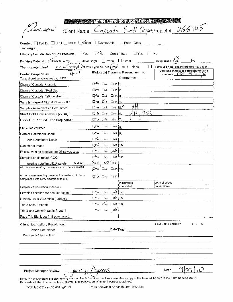
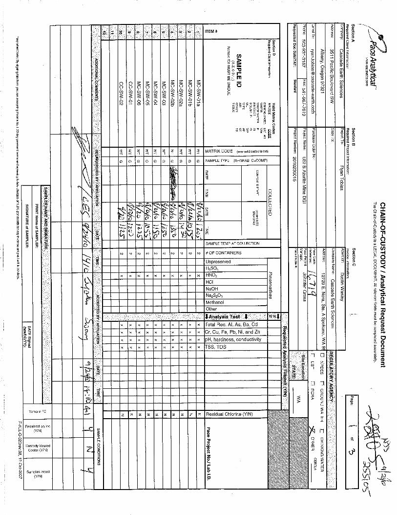


In association with H.J. Heinen
McCLELLAND LABORATORIES, INC. 1016 Greg Street, Sparks, Nevada 89431 (775) 356-1300
FAX (775) 356-8917
E-MAIL [email protected]
December 27, 2007
Mr. Bob LambethCascade Earth Sciences12720 E. Nora Ave., Suite ASpokane, WA 99216
Dear Bob:
Enclosed is our summary report concerning results obtained from short term (7 weeks) humiditycell (HC) kinetic ARD potential tests conducted on samples LWR-1 and UWR-1 and for thesequential batch soils attenuation test conducted on the soils weighted composite (soils samplesTP-5, S-1 @ 4'; TP-5, S1 (or 2) @ 8'; and TP-6, S-1 @ 4') using the volume weighted HC testextract composite (weeks 0, 1, 2, 3, 4) from sample UWR-1, as influent. A complete writtenreport can be provided later if necessary for your report.
The invoice for this work (MLI Job No. 3237 / 7035) was sent under separate cover.
We appreciated the opportunity to serve you on this project and hope the data reached you in atimely manner. We look forward to a lasting association.
Sincerely,
Gene E. McClellandMetallurgist/President
GEM:cdEnclosure

In association with H.J. Heinen
McCLELLAND LABORATORIES, INC. 1016 Greg Street, Sparks, Nevada 89431 (775) 356-1300
FAX (775) 356-8917
E-MAIL [email protected]
Summary Reporton
Short Term HC Tests (LWR-1 and UWR-1) and SequentialBatch Soils Attenuation Test (Soils Weighted Composite)
MLI Job No. 3237December 27, 2007
for
Mr. Bob LambethCascade Earth Sciences
12720 E. Nora Ave., Suite ASpokane, WA 99216
TABLE OF CONTENTS
EXECUTIVE SUMMARY . . . . . . . . . . . . . . . . . . . . . . . . . . . . . . . . . . . . . . . . . . . . . . . . . . . . . 1
SAMPLE PREPARATION AND FEED ANALYSES . . . . . . . . . . . . . . . . . . . . . . . . . . . . . . . 3Table 1. - Composite Make-Up Information, Site Native Soils Samples . . . . . . . . . . . . . 3Table 2. - Metals Analysis Results, UWR-1 and Soils Feed Solids . . . . . . . . . . . . . . . . . 4Table 3. - Modified Acid/Base Accounting (Mod ABA) Static ARD Potential
Test Data, HC Test Feed Solids . . . . . . . . . . . . . . . . . . . . . . . . . . . . . . . . . . . . . . . 4Table 4. - Modified Acid/Base Accounting (Mod ABA) Static ARD Potential
Test Results, Soils Samples . . . . . . . . . . . . . . . . . . . . . . . . . . . . . . . . . . . . . . . . . . 4
HC KINETIC ARD POTENTIAL TEST PROCEDURES AND RESULTS . . . . . . . . . . . . . 5Table 5. - UWR-1 HC Test Extract Composite Make-Up Information . . . . . . . . . . . . . . . 5Table 6. - Humidity Cell Analytical Results, LWR-1 (2.4728 kg) . . . . . . . . . . . . . . . . . . 6
Figure 1a. - Weekly Humidity Cell Analytical Results, LWR-1 . . . . . . . . . . . . . . 6Figure 1b. - Cumulative Humidity Cell Analytical Results, LWR-1 . . . . . . . . . . 6
Table 7. - Humidity Cell Analytical Results, UWR-1 (2.4844 kg) . . . . . . . . . . . . . . . . . . 6Figure 2a. - Weekly Humidity Cell Analytical Results, UWR-1 . . . . . . . . . . . . . 6Figure 2b. - Cumulative Humidity Cell Analytical Results, UWR-1 . . . . . . . . . . 6
Table 8. - Multi-Element ICP Metals Analysis Results, Humidity Cell TestExtracts, Sample LWR-1 . . . . . . . . . . . . . . . . . . . . . . . . . . . . . . . . . . . . . . . . . . . . 7
Table 9. - Multi-Element ICP Metals Analysis Results, Humidity Cell TestExtracts, Sample UWR-1 . . . . . . . . . . . . . . . . . . . . . . . . . . . . . . . . . . . . . . . . . . . . 7

Mr. Bob Lambeth / Cascade Earth SciencesTable of Contents - December 27, 2007
ii
McCLELLAND LABORATORIES, INC.
SEQUENTIAL BATCH SOILS ATTENUATION TEST PROCEDURE AND RESULTS . . . . 8Table 10. - Sequential Batch Soils Attenuation Test Data, UWR-1 HC Test
Extract Composite Used as Influent . . . . . . . . . . . . . . . . . . . . . . . . . . . . . . . . . . . 9Table 11. - Metals Analysis Results, Influent and Effluents,
Sequential Batch Soils Attenuation Test, UWR-1 Composite HC TestExtract (Weeks 0, 1, 2, 3, 4) Used as Influent . . . . . . . . . . . . . . . . . . . . . . . . . . . . 9
Table 12. - Overall Attenuation Data (Mass Basis), Sequential Batch SoilsAttenuation Test, UWR-1 Composited HC Test Extract Used as Influent . . . . . 10
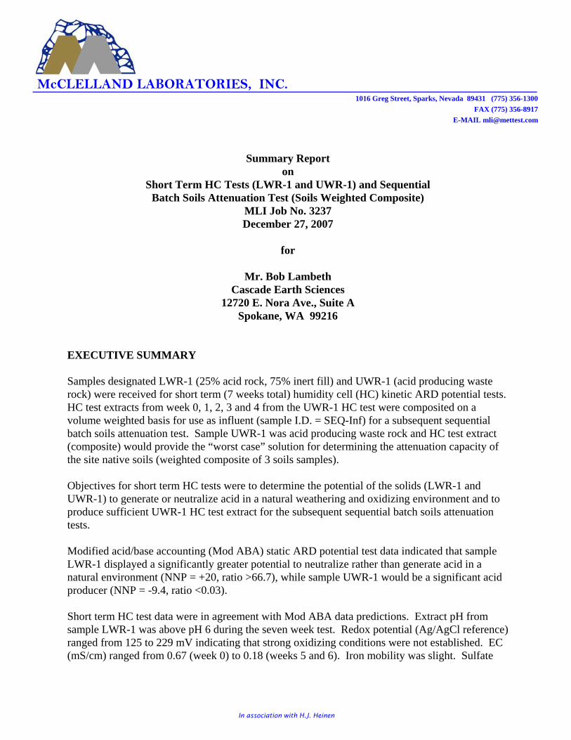
In association with H.J. Heinen
McCLELLAND LABORATORIES, INC. 1016 Greg Street, Sparks, Nevada 89431 (775) 356-1300
FAX (775) 356-8917
E-MAIL [email protected]
Summary Reporton
Short Term HC Tests (LWR-1 and UWR-1) and SequentialBatch Soils Attenuation Test (Soils Weighted Composite)
MLI Job No. 3237December 27, 2007
for
Mr. Bob LambethCascade Earth Sciences
12720 E. Nora Ave., Suite ASpokane, WA 99216
EXECUTIVE SUMMARY
Samples designated LWR-1 (25% acid rock, 75% inert fill) and UWR-1 (acid producing wasterock) were received for short term (7 weeks total) humidity cell (HC) kinetic ARD potential tests. HC test extracts from week 0, 1, 2, 3 and 4 from the UWR-1 HC test were composited on avolume weighted basis for use as influent (sample I.D. = SEQ-Inf) for a subsequent sequentialbatch soils attenuation test. Sample UWR-1 was acid producing waste rock and HC test extract(composite) would provide the “worst case” solution for determining the attenuation capacity ofthe site native soils (weighted composite of 3 soils samples).
Objectives for short term HC tests were to determine the potential of the solids (LWR-1 andUWR-1) to generate or neutralize acid in a natural weathering and oxidizing environment and toproduce sufficient UWR-1 HC test extract for the subsequent sequential batch soils attenuationtests.
Modified acid/base accounting (Mod ABA) static ARD potential test data indicated that sampleLWR-1 displayed a significantly greater potential to neutralize rather than generate acid in anatural environment (NNP = +20, ratio >66.7), while sample UWR-1 would be a significant acidproducer (NNP = -9.4, ratio <0.03).
Short term HC test data were in agreement with Mod ABA data predictions. Extract pH fromsample LWR-1 was above pH 6 during the seven week test. Redox potential (Ag/AgCl reference)ranged from 125 to 229 mV indicating that strong oxidizing conditions were not established. EC(mS/cm) ranged from 0.67 (week 0) to 0.18 (weeks 5 and 6). Iron mobility was slight. Sulfate

Mr. Bob Lambeth / Cascade Earth SciencesMLI Job No. 3237 - December 27, 2007
2
McCLELLAND LABORATORIES, INC.
concentrations ranged from 280 to 7.4 mg/L. Acidity was not detected in any extract anddemonstrates that none of the sulfate generated resulted from oxidation of sulfide minerals. Alkalinity concentrations were high and ranged from 46 (week 0) to 70 (week 6) mgCaCO3/L.
HC test data show that sample UWR-1 was likely acid producing before sample acquisition. Extract pH ranged from 2.66 (week 0) to 2.31 (week 5). Redox potential ranged from 410(week 1) to 532 (week 6) mV and demonstrate that strong oxidizing conditions were establishedduring the kinetic test. EC was fairly constant during the test and ranged from 2.17 (week 6) to3.31 (week 4) mS/cm. Iron mobility was fairly significant (313 to 428 mg/L) and the ferric toferrous ratio was greater than 1 after week 2. Sulfate and acidity concentrations were high theduration of the test, and all the sulfate generated resulted from oxidation of contained sulfideminerals. Alkalinity was not detected in any HC test extract.
Sequential batch soils attenuation test data show that site native soils display a significantcapacity to attenuate acidic components and regulated metals from the UWR-1 composite extractsolution. Soils readily attenuated acidic components; 99.99% of the Fe, 66.40% of the sulfate,99.53% of the acidity contained in the extract composite used as influent for the attenuation test. Metals analysis results available show that the soils attenuated 98.77% of the As, 88.61% of theCd, 99.06% of the Cu, 95.28% of the Mn, 72.51% of the Zn. Lead was mobilized from the soils.
(Text to be completed after ACZ results.)

Mr. Bob Lambeth / Cascade Earth SciencesMLI Job No. 3237 - December 27, 2007
3
McCLELLAND LABORATORIES, INC.
SAMPLE PREPARATION AND FEED ANALYSES
About 4 kg each of samples LWR-1 and UWR-1 were received for short term HC kinetic ARDpotential tests. Each sample was stage crushed in entirety to 100%-1/4" (~P8010 mesh) in size, andwas blended and split to obtain 2.5 kg for HC tests.
Three soil samples were received at a minus 3/4" feed size. The entire quantity of each soilsample was composited to produce sufficient sample for the three sequence, sequential batch soilsattenuation test. Composite make-up information is provided in Table 1.
Table 1. - Composite Make-Up Information, Site Native Soils SamplesWeight, kg Weight,
Soil Sample I.D. Rec’d To Comp percentTP-5, S-1 @ 4' 2.2 2.2 30.6TP-5, S-1 @ 8' 1) 2.6 2.6 36.1TP-6, S-1 @ 4' 2.4 2.4 33.3Composite 7.2 7.2 100.0
1) Sample I.D. on sample bag was T-5, S-2 @ 8', but on the packing list was as above.
The soils composite (7.2 kg) was thoroughly blended and split to obtain 2.500 kg for sequence 1(S-1), 2.097 kg for sequence 2 (S-2) and 1.747 kg for sequence 3 (S-3). Rejects (0.856 kg) wereused to determine feed moisture content (11.7% moisture).
Cascade Earth Sciences (CES) had all feed analyses conducted on all feed solids and providedMLI respective results. Metals analysis results are provided in Table 2. Mod ABA results forLWR-1, UWR-1 and the three soils samples are provided in Tables 3 and 4, respectively.

Mr. Bob Lambeth / Cascade Earth SciencesMLI Job No. 3237 - December 27, 2007
4
McCLELLAND LABORATORIES, INC.
Table 2. - Metals Analysis Results, UWR-1 and Soils Feed SolidsFeed Solid Sample
Metal, mg/kg UWR-1 TP-5, S-1 TP-5, S-21) TP-6, S-1 TP Wt’d. Avg.2)
Aluminum NR NR NR NR NR
Arsenic 195 72.2 88.4 93.4 84.7Cadmium 0.44 0.61 0.95 1.51 1.02Calcium NR NR NR NR NR
Copper 546 180 262 306 249Iron 137,000 53,000 54,600 62,300 56,633Lead 16.30 14.50 14.10 829 285.87Magnesium NR NR NR NR NR
Manganese NR NR NR NR NR
Mercury 0.92 0.05 ND 0.70 0.25Sodium NR NR NR NR NR
Zinc 115 199 223 479 300NR = No Result; ND = Not Detected1) Sample I.D. on sample bag was TP-5, S-2 @ 8', but on packing list was TP-5, S-1 @ 8'2) Each soil sample received was essentially the same weight (2.4 kg), so the soils composite (total wt. of each combined) was a weightedcomposite.Note: Metals analysis results for feed solids provided by Cascade Earth Sciences.
Metals analysis results show that sufficient quantities of As, Cd, Cu, Fe, Pb, Hg and Zn arecontained in the UWR-1 feed to be mobilized during the HC test, especially because acidproducing conditions were established. Calculated results for the site native soils compositeshow that sufficient quantities of those same metals are contained in the soils to be mobilizedfrom the soils during the sequential batch soils attenuation test.
Table 3. - Modified Acid/Base Accounting (Mod ABA)Static ARD Potential Test Data, HC Test Feed Solids
Sample Sulfur, weight percent (as S)I.D. Total SO4 Pyritic S= Org. S AGP1) ANP NNP Ratio
LWR-1 0.02 <0.01 <0.01 0.03 <0.3 20 +20 >66.67UWR-1 3.16 0.91 0.30 1.95 9.4 <0.3 -9.4 <0.03
1) AGP based on pyritic S= content (S=% x 31.25). AGP, ANP, NNP in units of tons CaCO3 equivalents per 1000 tons of solids.Note: Mod ABA results provided by Cascade Earth Sciences.
Table 4. - Modified Acid/Base Accounting (Mod ABA)Static ARD Potential Test Results, Soils Samples
Soil Sulfur, weight percent (as S)Sample Total SO4 Pyritic S= Org. S AGP1) ANP NNP Ratio
TP-5, S-1 @ 4' 0.06 0.02 0.01 0.03 0.3 2 +1.7 6.67TP-5, S-1 @ 8' 0.03 0.01 <0.01 0.02 <0.3 8 +8.0 >16.67TP-6, S-1 @ 4' 0.06 0.02 <0.01 0.04 <0.3 5 +5.0 >16.67
Composite 0.05 0.017 0.003 0.03 <0.3 5 +5.0 >16.671) AGP based on pyritic S= content (S=% x 31.25). AGP, ANP, NNP in units of tons CaCO3 equivalents per 1000 tons of solids.Note: Mod ABA results provided by Cascade Earth Sciences, and were used to calculate the soils composite Mod ABA data on a weighted basis.
Mod ABA results were summarized in the Executive Summary of this report.

Mr. Bob Lambeth / Cascade Earth SciencesMLI Job No. 3237 - December 27, 2007
5
McCLELLAND LABORATORIES, INC.
HC KINETIC ARD POTENTIAL TEST PROCEDURES AND RESULTS
Short term HC kinetic ARD potential tests were conducted on 2.5 kg charges of LWR-1 andUWR-1 at a 100%-1/4" (~ P8010 mesh) feed size to assess the potential of the solids to generate orneutralize acid in a natural weathering and oxidizing environment.
The short term HC tests were conducted for 7 weeks (including week 0 saturation) using ASTMStandard Method D5744-96 (02). Detailed test procedures are not provided in this summaryreport. Weekly HC test extract volumes were measured by weighing. Samples of each extractwere analyzed immediately by MLI personnel for Temp., DO content, Eh (redox potential), pH,conductivity (EC), sulfate, acidity, alkalinity, Fet, Fe2+ and Fe3+ (by difference). Temperaturesfor both HC tests ranged from 19.3 to 22.0 EC. Dissolved oxygen contents ranged from 3.9 to7.3 ppm. Those data are not included in the HC test tables (Tables 6 and 7). Remaining extractwas filtered through a 0.45µm filter, preserved for metals analyses (pH <2.0 w/HNO3) andshipped overnight to ACZ Laboratories for the suite of metals analyses requested by CES.
HC test extract solution rejects (minus volumes required for all analyses) from the UWR-1 HCtest were stored frozen (unfiltered, unpreserved) until the volume weighted extract compositecould be prepared. Volume weighted extract composite make-up information is provided inTable 5.
Table 5. - UWR-1 HC Test Extract Composite Make-Up InformationHC Test Extract Volume,
Week Vol., mL percent0 500.0 11.71 928.4 21.72 975.3 22.83 924.2 21.64 949.9 22.2
Composite 4,227.8 100.0
The volume weighted HC test extract composite was prepared by thawing each weekly extractand combining the total available volume of each. A sample was obtained from the composite(150 mL), was filtered through a 0.45µm filter, was preserved for metals analysis (pH <2.0w/HNO3) and was shipped overnight to ACZ for the sequential suite of metals analyses. Thatsample was labeled SEQ-Inf. Remaining extract composite (unfiltered, unpreserved) was used asinfluent (SEQ-Inf) for the subsequent sequential batch soils attenuation test.
Both HC tests continued through 6 weeks (7 weeks with week 0). HC test data for samplesLWR-1 and UWR-1 are provided in Tables 6 and 7, respectively. On the sample page of Tables6 and 7 are Figures 1 a & b and 2 a & b which depict graphically weekly pH, sulfate, acidity andalkalinity (a figures) and cumulative (b figures) data on a mass basis.

Mr. Bob Lambeth / Cascade Earth SciencesMLI Job No. 3237 - December 27, 2007
6
Vol. Effluent Redox, mV Conductivity Cum. Fe2+ Fe3+ Cum. Cum. Cum.Week L pH (vs Ag/AgCI) mS/cm mg/l mg/kg mg/kg mg/l mg/l mg/l mg/kg mg/kg mg/l mg/kg mg/kg mg/l mg/kg mg/kg
0 0.708 7.05 125 0.67 0.07 0.020 0.020 0.01 0.06 280.0 80.17 80.17 0.0 0.00 0.00 46.00 13.17 13.171 1.099 7.08 195 0.25 0.01 0.004 0.024 0.00 0.01 61.0 27.11 107.28 0.0 0.00 0.00 52.00 23.11 36.282 1.156 6.60 196 0.24 0.03 0.014 0.038 0.01 0.02 11.4 5.33 112.61 0.0 0.00 0.00 56.00 26.18 62.463 1.202 6.20 200 0.20 0.09 0.044 0.082 0.00 0.09 30.1 14.63 127.24 0.0 0.00 0.00 62.00 30.14 92.604 1.196 6.45 229 0.19 0.01 0.005 0.087 0.00 0.01 16.5 7.98 135.22 0.0 0.00 0.00 46.00 22.25 114.855 1.169 6.77 192 0.18 0.02 0.009 0.096 0.00 0.02 7.4 3.50 138.72 0.0 0.00 0.00 56.00 26.47 141.326 1.161 6.50 228 0.18 0.00 0.000 0.096 0.00 0.00 9.2 4.32 143.04 0.0 0.00 0.00 70.00 32.87 174.1989
101112131415161718192021
Vol. Effluent Redox, mV Conductivity Cum. Fe2+ Fe3+ Cum. Cum. Cum.Week L pH (vs Ag/AgCI) mS/cm mg/l mg/kg mg/kg mg/l mg/l mg/l mg/kg mg/kg mg/l mg/kg mg/kg mg/l mg/kg mg/kg
0 0.820 2.66 416 2.75 313.00 103.309 103.309 243.00 70.00 1170.0 386.17 386.17 1548.0 510.93 510.93 0.00 0.00 0.001 1.113 2.64 410 2.64 317.00 142.015 245.324 162.00 155.00 930.0 416.64 802.81 1568.0 702.46 1213.39 0.00 0.00 0.002 1.160 2.54 436 2.63 328.00 153.148 398.472 201.00 127.00 557.0 260.07 1062.88 1652.0 771.34 1984.73 0.00 0.00 0.003 1.109 2.38 478 2.61 244.00 108.918 507.390 63.00 181.00 1170.0 522.27 1585.15 1444.0 644.58 2629.31 0.00 0.00 0.004 1.135 2.39 466 3.31 428.00 195.532 702.922 168.00 260.00 1510.0 689.84 2274.99 2284.0 1043.45 3672.76 0.00 0.00 0.005 1.099 2.31 501 3.18 348.00 153.941 856.863 124.00 224.00 2270.0 1004.16 3279.15 2298.0 1016.54 4689.30 0.00 0.00 0.006 1.139 2.35 532 2.17 268.00 122.867 979.730 35.00 233.00 2140.0 981.11 4260.26 1546.0 708.78 5398.08 0.00 0.00 0.0089
101112131415161718192021
Table 7. - Humidity Cell Analytical Results, UWR-1 (2.4844 kg)
Total Fe SO4= Acidity, CaCO3 Equivalents Alkalinity, CaCO3 Equivalents
Table 6. - Humidity Cell Analytical Results, LWR-1 (2.4728 kg)
Total Fe SO4= Acidity, CaCO3 Equivalents Alkalinity, CaCO3 Equivalents
Figure 1a.- Weekly Humidity Cell Analytical Results, LWR-1
3
4
5
6
7
8
0 1 2 3 4 5 6 7 8 9 10
Weeks
Efflu
ent p
H,s
tu
0
20
40
60
80
100
Wee
kly
mg/
kg s
olid
s
pH Sulfate Acidity Alkalinity
Figure 1b.- Cumulative Humidity Cell Analytical Results, LWR-1
3
4
5
6
7
8
0 1 2 3 4 5 6 7 8 9 10
Weeks
Efflu
ent p
H,s
tu
0
60
120
180
240
300
Wee
kly
mg/
kg s
olid
s
pH Sulfate Acidity Alkalinity
Figure 2a.- Weekly Humidity Cell Analytical Results, UWR-1
2
3
4
5
6
7
0 1 2 3 4 5 6 7 8 9 10
Weeks
Efflu
ent p
H,s
tu
0
300
600
900
1200
1500
Wee
kly
mg/
kg s
olid
s
pH Sulfate Acidity Alkalinity
Figure 2b.- Cumulative Humidity Cell Analytical Results, UWR-1
2
3
4
5
6
7
0 1 2 3 4 5 6 7 8 9 10
Weeks
Efflu
ent p
H,s
tu
0
1200
2400
3600
4800
6000
Wee
kly
mg/
kg s
olid
s
pH Sulfate Acidity Alkalinity
McCLELLAND LABORATORIES, INC.

Mr. Bob Lambeth / Cascade Earth SciencesMLI Job No. 3237 - December 27, 2007
7
McCLELLAND LABORATORIES, INC.
HC test data was discussed in some detail in the Executive Summary of this report. Data showthat sample LWR-1 would neutralize acid, but sample UWR-1 would generate acid in a naturalweathering and oxidizing environment.
Multi-element ICP metals analysis results for weeks 0, 1, 2, 3 and 4 HC test extracts for LWR-1and UWR-1 are provided in Tables 8 and 9, respectively. ACZ report sheets for these analysesare on file at CES and are not appended to this summary report.
Table 8. - Multi-Element ICP Metals Analysis Results,Humidity Cell Test Extracts, Sample LWR-1
ExtractAnalysis, mg/L Week 0 Week 1 Week 2 Week 3 Week 4Aluminum 0.194 0.032 0.033* Pending 0.022Arsenic 0.0035 0.0031 0.0049 0.0041Cadmium 0.0006 0.00011) 0.00031) <0.0001Calcium 133 48.4 44.2 28.7Copper 0.0292 0.0063 0.0068* 0.0104Iron 0.53 0.031) <0.02 <0.02Lead 0.0008 0.0006 0.00041) 0.00011)
Magnesium 8.4 2.9 2.6 1.8Manganese 0.0543 0.0051 0.0411* 0.0042Mercury <0.0002 <0.0002 <0.0002 <0.0002Sodium 8.5 3.7 3.1 1.81)
Zinc 0.014 0.0031) 0.013* 0.0051)
* Refer to ACZ extended qualifier report for detail.1) ACZ report qualified result with a B designation. B = analyte conc. detected at a value between MDL and PQL.
Table 9. - Multi-Element ICP Metals Analysis Results,Humidity Cell Test Extracts, Sample UWR-1
ExtractAnalysis, mg/L Week 0 Week 1 Week 2 Week 3 Week 4Aluminum 130 133 129 Pending 137Arsenic 0.027 0.028 0.0409* 0.11)
Cadmium 0.0705 0.0572 0.0457 0.0430Calcium 137 135 128 98.5Copper 7.8 3.1 3.6 6.1Iron 342 372 325 245Lead 0.0189 0.0151 0.0155 0.0080Magnesium 48.7 80.7 70.0 41.1Manganese 10.7 12.8 12.1 5.7Mercury 0.0003*1) <0.0002 <0.0002 0.00021)
Sodium 7.3 7.2 5.4 4.1Zinc 3.74 4.57 4.8 5.3* Refer to ACZ extended qualifier report for detail.1) ACZ report qualified result with a B designation. B = analyte conc. detected at a value between MDL and PQL.
HC test extract metals analysis results show that potential for metals mobility was significantlyless from sample LWR-1 (acid neutralizing) than from sample UWR-1 (acid generating).

Mr. Bob Lambeth / Cascade Earth SciencesMLI Job No. 3237 - December 27, 2007
8
McCLELLAND LABORATORIES, INC.
SEQUENTIAL BATCH SOILS ATTENUATION TEST PROCEDURE AND RESULTS
A sequential batch soils attenuation test, using volume weighted composite extract from theUWR-1 HC test as influent, was conducted to assess the capacity of the site soils composite forattenuating acid components and metals contained in the “worst case” influent. It was decided toconduct a column percolation sequential batch test rather than a bottle roll sequential batch test tobetter simulate site conditions. At site, seepage solution from UWR-1 would pass through theunderlying site native soils only once, and equilibrium conditions would not be established. Thebottle roll (agitated) sequential batch test procedure is a dynamic test (percolation is a static test)and equilibrium conditions (24 hours of rolling/sequence) would be established. The percolationmethod is more conservative because constituent mobility from the soils is typically higher innon-equilibrium conditions, and attenuation capacity of the soils, for some constituents, is lessfor non-equilibrium conditions.
Influent solution volume available was used to back calculate the appropriate soils charge foreach of the three sequences. Appropriate weights of soils were placed into three 4" I.D. x 12"high clear acrylic columns and bed heights were measured. For sequence 1, influent (SEQ-Inf)was pumped onto the first soils composite charge at a rate equivalent to the site 100 yr/24 hrstorm event rate (6.5" rain in 24 hrs). That application rate was 0.00325 gpm/ft2 of columncross-sectional area (1.074 mL/min, 1.546 L/24 hrs). Influent was pumped at constant rate usinga peristaltic pump. At the pumping rate, 2.43 days was required to complete sequence 1. Aftersome drain time (~ 2 hrs), effluent volume from sequence 1 soils was measured by weighing andsamples were taken for required analyses. A pre-calculated volume of sequence 1 effluent (S-1)was applied at the same rate to the pre-calculated weight of soils in the sequence 2 column. Theabove procedure was used through three sequences. The total volume of influent applied to therespective soils charges was equivalent to 1.5 tons solution applied per ton of soils, which isin-turn equivalent to 6 pore volumes passing through the soils.
Effluents from each sequence (S-1, S-2, S-3) were sampled and analyzed immediately for Eh,pH, EC, sulfate, acidity, alkalinity and Fet by MLI personnel. Another 75 mL sample of eacheffluent was filtered through a 0.45µm filter, preserved for metals analysis (pH <2.0 w/HNO3),and shipped overnight to ACZ for requested metals analyses.
Sequential batch soils attenuation test data is provided in Table 10. Metals analysis results fortest influent and effluents is provided in Table 11.

Mr. Bob Lambeth / Cascade Earth SciencesMLI Job No. 3237 - December 27, 2007
9
McCLELLAND LABORATORIES, INC.
Table 10. - Sequential Batch Soils Attenuation Test Data,UWR-1 HC Test Extract Composite Used as Influent
Sequence EffluentInfluent S-1 S-2 S-3
Soil Wt., kg N/A 2.500 2.097 1.747Soil Vol., ft3 N/A 0.074 0.064 0.053Soil Bulk Density, lb/ft3 N/A 74.4 72.2 72.6Influent Volume, L 3.750 3.750 3.145 2.620Effluent Volume, L N/A 3.568 2.787 2.296Temperature, EC Start 18.6 19.3 20.2Temperature, EC End 19.3 20.2 18.0Eh, mV 444 268 325 271pH, s.u. 2.51 4.54 5.35 6.02EC, mS/cm 2.79 1.43 0.90 0.56DO, ppm 6.1 8.1 6.8 6.8Iron, mg/L 328 0.06 0.16 0.03Sulfate, mg/L 1,054 774 564 354Acidity, mg/L (as CaCO3) 1,717 44 12 8Alkalinity, mg/L (as CaCO3) 0 0 4 2Note: Eh, pH, EC, DO, Fe, SO4, acidity and akalinity data were from MLI analytical results from the UWR-1 HC test (weeks 0, 1, 2, 3, 4) andwere calculated on a volume weighted basis.
Table 11. - Metals Analysis Results, Influent and Effluents,Sequential Batch Soils Attenuation Test, UWR-1 Composite
HC Test Extract (Weeks 0, 1, 2, 3, 4) Used as InfluentSequence Effluent
Metal, mg/L Influent S-1 S-2 S-3Aluminum 143 2.7 0.19 1.4Arsenic 0.0562 0.0009 0.00091) 0.00071)
Cadmium 0.0482 0.0217 0.0091 0.0055Calcium 117 221 139Copper 5.2 0.0174 0.0099 0.0487Iron 293 0.16 0.07Lead 0.0071 0.0774 0.0402 0.0144Magnesium 55.1 57.9 39.3Manganese 10.6 14.5 1.83 0.5Mercury <0.0002 0.00021) <0.0002Sodium 5.1 7.9 8.6Zinc 5.1 6.7 1.85 1.41) ACZ report qualified result with a B designation. B = analyte conc. detected at a value between MDL and PQL
Solution volumes and constituent concentrations were used to calculate soilsattenuation/mobilization data on a mass basis. Effluent volume through three soils sequenceswas equivalent to the influent volume (3.75 L) based on the assumption, that at site, all solutionapplied would pass through the total soils volume (0.191 ft3). Using equivalent volumesprovides a conservative assessment of soils attenuation capacity because the volume of effluentfrom sequence 3 (S-3) was much less at 2.296 L. Mass balance calculations were not made forindividual sequences, but only for the overall three sequence test series.

Mr. Bob Lambeth / Cascade Earth SciencesMLI Job No. 3237 - December 27, 2007
10
McCLELLAND LABORATORIES, INC.
Overall attenuation data on a mass basis is provided in Table 12.
Table 12. - Overall Attenuation Data (Mass Basis), Sequential Batch Soils Attenuation Test,UWR-1 Composited HC Test Extract Used as InfluentInfluent Effluent (S-3)
Vol., Conc., Vol., Conc., AttenuatedConstituent L mg/L mg L2) mg/L mg mg mg/ft3 %Iron1) 3.750 328 1,230.000 3.750 0.03 0.112 1,229.888 6,439 99.99Sulfate1) 3.750 1,054 3,953 3.750 354 1,328 2,625 13,743 66.40Acidity1) 3.750 1,717 6,439 3.750 8 30 6,409 33,555 99.53Alkalinity1) 3.750 0 0 3.750 2 7.5 -7.5 -39.3 N/A
Aluminum 3.750 143 536.3 3.750 1.4 5.25 531.05 2,780.4 99.02Arsenic 3.750 0.0562 0.2108 3.750 0.0007 0.0026 0.2082 1.09 98.77Cadmium 3.750 0.0482 0.1808 3.750 0.0055 0.0206 0.1602 0.84 88.61Calcium 3.750 117 438.75 3.750Copper 3.750 5.2 19.5 3.750 0.0487 0.183 19.317 101.14 99.06Iron 3.750 293 1,098.750 3.750Lead 3.750 0.0071 0.0266 3.750 0.0144 0.0540 -0.0274 -0.14 -103.01Magnesium 3.750 55.1 206.6 3.750Manganese 3.750 10.6 39.75 3.750 0.5 1.875 37.875 198.30 95.28Mercury 3.750 <0.0002 0.00 3.750Sodium 3.750 5.1 19.1 3.750Zinc 3.750 5.1 19.1 3.750 1.4 5.25 13.85 72.51 72.511) Consituent concentrations calculated on a volume weighted basis from weekly ARD analyses from the UWR-1 HC test.2) The 3.750 L volume was used assuming all influent applied would pass through the soils - provides worst case data because the S-3 effluent volume was 2.296 L.
Overall mass data, for available solution analyses, show that site native soils display a significantattenuation capacity for acidic components (Fe, SO4, acidity, Eh, pH and EC). Site native soilsattenuated 99.99% of Fe, 66.40% of SO4, 99.53% of acidity. Alkalinity was mobilized, to somedegree, from the soils. Available attenuation test effluent constituent concentration data indicatethat the soils effectively attenuate As, Cd, Cu, Fe, Mn and Zn. Lead and Na appeared tomobilize from the soils.
Gene E. McClellandMetallurgist/President

Appendix E.
Technical Specifications and Construction Quality Assurance Plan

AAzzuurriittee MMiinnee
((PPNN:: 22001100223300001155))
TTeecchhnniiccaall SSppeecciiffiiccaattiioonnss

Cascade Earth Sciences – Spokane, WA Azurite Mine Removal Action PN: 2010230015 / Doc: Azurite Spec Index.docx April 2011
i
TECHNICAL SPECIFICATION INDEX
AZURITE MINE
DIVISION 01 GENERAL
00100 Measurement and Payment 00190 Mobilization DIVISION 02 SITE WORK
02110 Obliteration of Abandoned Roadways 02130 Clearing and Grubbing 02135 Waste Material Disposal 02136 Waste Material Disposal (Landfill) 02204 Loose Rock Riprap 02220 Excavation and Embankment 02228 Culvert Pipe and Pipe Arches 02251 Sediment Control 02270 Mechanically Stabilized Embankments and Abutments 02801 Seeding DIVISION 13 SPECIAL CONSTRUCTION
13001 HDPE Liner 13002 Non-Woven Geotextile 13003 Uniaxial Geogrid DIVISION 15 MECHANICAL 15050 Pipe and Fitting

Cascade Earth Sciences 00100 - 1 Azurite Mine Removal Action – Technical Specs PN: 2010230015 / Doc: 00100 Measurement And Payement.docx April 2011
DIVISION 01
SECTION 00100 MEASUREMENT AND PAYMENT
1.0 PART I - GENERAL
1.1 Measurement and Payment
Measurement and payment for contract work will be made only for and under those pay items included in the SCHEDULE OF ITEMS. All other work and materials will be considered as included in the payment for items shown. When more than one class, size, or thickness is specified in the SCHEDULE OF ITEMS for any pay item, suffixes will be added to the item number to differentiate between items to be bid.
1.2 Determination of Quantities
The following methods of measurement are used to determine contract quantities for payment. For individual construction items, longitudinal and lateral measurements for area computations will be made horizontally or corrected to horizontal measurement unless otherwise specified. Measurements for seeding, mulching, geotextiles, netting, erosion control blankets, and sodding will be along slope lines. The average end area method will be used to compute volumes of excavation or embankment. However, if in the judgment of the ENGINEER, the average end area method is impractical, measurement will be made by volume in hauling vehicles or by other three dimensional methods. Structures will be measured according to neat lines SHOWN ON THE DRAWINGS or as altered by the ENGINEER in writing to fit field conditions. For items that are measured by the linear foot, such as pipe culverts, fencing, guardrail, and under drains, measurements will be made parallel to the base or foundation upon which the structures are placed. Pipe and pipe arch culverts shall be measured along center of invert; arches shall be measured at spring line. For aggregates weighed for payment, the tonnage will not be adjusted for moisture content, unless otherwise provided in SPECIAL PROJECT SPECIFICATIONS. For bituminous material, volumes will be measured at 60F or will be corrected to the volume at 60F by using ASTM D 1250 for asphalts. Emulsified asphalt will be measured at 60F, or measured by converting the gallonage at another temperature to gallonage at 60F by means of the following formula:

Cascade Earth Sciences 00100 - 2 Azurite Mine Removal Action – Technical Specs PN: 2010230015 / Doc: 00100 Measurement And Payement.docx April 2011
Gallons at 60F = Gallons at AF 1+0.00025 (AF - 60F)
in which AF is the temperature of the material at the time the gallonage is measured. For vehicular shipments, net certified scale weights or weights based on certified volumes will be used as a basis of measurement. Measurements will be adjusted when bituminous material has been lost from the vehicle or the distributor, has been wasted, or has otherwise not been incorporated into this work. Determining true weights of hauling vehicles shall be made by weighing the empty vehicles at least once a day at the times the ENGINEER directs. Each vehicle shall bear a plainly legible identification mark. When bituminous materials are shipped, net certified weights, or volume corrected for loss of foaming, can be used for computing quantities. For standard manufactured items, such as fence, wire, plates, rolled shapes, pipe conduits, etc., identified by gauge, weight, section dimensions, etc., such identification shall be considered the nominal weights or dimensions. Unless controlled by tolerances in cited specifications, manufacturer's tolerances will be accepted.
1.3 Units of Measurement
Payment will be by units defined and determined according to U.S. Standard measure as follows:
A. Cubic Yard - A measurement computed by one of the following methods:
1. Excavation, Embankment, or Borrow - The measurement computed by the
average end area method from measurements made longitudinally along a centerline or reference line.
2. Material in Place or Stockpile - The measurement computed with
dimensions of the in-place material. 3. Material in the Delivery Vehicle - The measurement computed using
measurements of material in the hauling vehicles at the point of delivery. Vehicles shall be loaded to at least their water level capacity. Leveling of the loads may be required when vehicles arrive at the delivery point.
B. Cubic Yard Mile - A combination of linear and volumetric measurement
meaning the movement of a cubic yard of material 1 mile.
C. Each - One complete unit, which may consist of one or more parts.

Cascade Earth Sciences 00100 - 3 Azurite Mine Removal Action – Technical Specs PN: 2010230015 / Doc: 00100 Measurement And Payement.docx April 2011
D. MFBM - One thousand board feet measure based on nominal widths, thickness, and extreme usable length of each piece of lumber or timber actually incorporated in the job.
E. Station - One hundred linear feet measured horizontally.
F. Station Yard - A combination of linear and volumetric measurement meaning
the movement of a cubic yard of material one station.
G. Thousand Gallons Mile - A combination of linear and volumetric measurement meaning the movement of 1,000 gallons of material 1 mile.
H. Ton - Short ton consisting of 2,000 pounds.
I. Ton Mile - A combination of linear and weight measurement meaning the
movement of 1 ton of material 1 mile.
1.4 Methods of Measurement
One of the following methods of measurement for determining final payment is DESIGNATED on the SCHEDULE OF ITEMS for each pay item:
A. Designed Quantities (DQ) - These quantities denote the final number of units
to be paid for under the terms of the contract. They are based upon the original design data available prior to advertising the project. Original design data include the preliminary survey information, design assumptions, calculations, drawings, and the presentation in the contract. Changes in the number of units SHOWN in the SCHEDULE OF ITEMS may be authorized under any of the following conditions:
1. As a result of changes in the work authorized by the Contracting Officer. 2. As a result of the Contracting Officer determining that errors exist in the
original design data used to determine designed quantities that cause a pay item to change by 15 percent or more.
3. As a result of the CONTRACTOR submitting to the Contracting Officer a
written request showing evidence of errors in the original design data used to determine design quantities that cause a pay item total to change by 15 percent or more. The evidence must be verifiable and consist of calculations, drawings, or other data that show how the designed quantity is believed to be in error.
B. Staked Quantities (SQ) - These quantities are determined from staked
measurements prior to construction.
C. Actual Quantities (AQ) - These quantities are determined from measurements of completed work.

Cascade Earth Sciences 00100 - 4 Azurite Mine Removal Action – Technical Specs PN: 2010230015 / Doc: 00100 Measurement And Payement.docx April 2011
D. Vehicle Quantities (VQ) - These quantities are measured or weighed in hauling vehicles.
E. Lump Sum Quantities (LSQ) - These quantities denote one complete unit of work as required by or described in the contract, including necessary materials, equipment, and labor to complete the job. They will not be measured.
1.5 Price Adjustment for Out-of-Specification Bituminous Materials
Bituminous materials are defined as all types and grades of asphalt cement, liquid asphalt, emulsified asphalt, and dust oil. If bituminous material fails one or more test requirements, and the Contracting Officer determines it is in the public interest to accept the material at a reduced price, the price reduction shall be based on the test results giving the largest percent price adjustment. The CONTRACTOR may remove and replace the defective material or accept the adjustment. The price reduction shall apply to all pay items affected. Price adjustment will be based on samples taken in duplicate in accordance with AASHTO T 40 under the supervision of the ENGINEER. Samples shall be sent to an authorized laboratory. The laboratory shall test one of each duplicate sample and retain the other. When any test result is not within the specification limits, the laboratory shall immediately notify the supplier and the ENGINEER. The ENGINEER will then authorize check testing of the retained sample. If the retained sample tests satisfactorily, the material will be accepted. If the retained sample also fails, the following schedule of price adjustments shall apply. The average of test values for the two samples will determine the basis for price adjustment, except when test results on the samples differ by more than the applicable AASHTO or ASTM Repeatability Unit; then, the test result numerically nearest the specification requirement will be used. (A repeatability unit is defined as D2S or D2S% limit for single operator precision described in ASTM recommended practice C 670.) The schedule of price adjustments shall not apply to the following tests:
Test AASHTO Test Method Spot Test T 102 Particle Charge T 59 Ductility T 51
Bituminous materials failing to meet specifications for these tests shall be removed and replaced.

Cascade Earth Sciences 00100 - 5 Azurite Mine Removal Action – Technical Specs PN: 2010230015 / Doc: 00100 Measurement And Payement.docx April 2011
See Table 00100-1 for the schedule of price adjustments for bituminous materials that do not meet specifications.
Table 00100-1
Schedule of Price Adjustments for Out-of-Specification Bituminous Materials.
Application
Deviation from Specification Limit Measured in Reproducibility Units*.
Less than
1
1 but less than
2
2 but less than
3
3 or greater
Price reduction applicable to bituminous base course and pavement mixture or to seal coat and bituminous material paid for as a separate item.
0% 5% 25% Remove &
Replace
Price reduction applicable to bituminous material paid for as a separate item.
0% 10% 25% Remove &
Replace * A reproducibility unit is defined as D2S or D2S% limit for multi-laboratory precision
described in ASTM recommended practice C 670.
The Sieve Test (AASHTO T 59) results may be exempt from the Schedule of Price Adjustments provided the CONTRACTOR's quality assurance program includes checking the uniformity of bituminous spread rates in increments no greater than 1 foot over the width of the spray bar and variation between increments is no greater than 5 percent.
1.6 Earthwork Tolerances
Adjustments of horizontal or vertical alignment, within the tolerances specified in this contract, or shifts of balance points up to 100 feet shall be made by the CONTRACTOR as necessary to produce the designed roadway section and to balance earthwork. Such adjustments shall not be considered as "Changes."
1.7 Pay Items, Unit Quantities, and Units of Measurement
The following table outlines the pay items, unit quantities, and the unites of measurement for the project.

Cascade Earth Sciences 00100 - 6 Azurite Mine Removal Action – Technical Specs PN: 2010230015 / Doc: 00100 Measurement And Payement.docx April 2011
Pay Item QuantityUnit
Quantities Units of
Measurement
Logistics Mobilize/Demob 1 EA LSQ Erosion / Sediment Control 1 EA LSQ Site Seeding (USFS Provided seed) 2 AC AQ Access Road Maintenance 1 EA LSQ Misc. Onsite Road Construction/Obliteration 1 EA LSQ Remote Camp/Porta Potties/Logistics 1 EA LSQ
Wasterock - Excavation and Placement Lower WR Excavation and Placement 6000 CY AQ Upper WR Excavation and Placement 16000 CY AQ Site Grading - WR footprint 6000 SY AQ
15-ft Stabilized Slope (300-ft) Earth Fill (1/2-inch minus talus) 3200 CY AQ Turf Reinforcement Mat 6000 SF AQ Uniaxial Geogrid 42000 SF AQ Tensar BX 1120 mat 35000 SF AQ
5-ft Berm (450-ft) Berm (Borrow Soil) 500 CY AQ
Repository - Regrading and Cover Construction Wasterock and Mill Area Bench Grading 180000 SF AQ Non-Woven Filter Fabric (12oz) 180000 SF AQ 40-mil HDPE Geomembrane 180000 SF AQ Non-Woven Filter Fabric (12oz) 180000 SF AQ Miragrid 7XT Geogrid 180000 SF AQ Talus Cover (12-inch depths) 7000 CY AQ
Runon / Runoff Control 4" Perforated Pipe 400 LF AQ 8 oz fabric 3500 SF AQ Impermeable Liner 4500 SF AQ Runon Control Ditch 1100 CY AQ V Ditches 250 CY AQ Infiltration basin 150 CY AQ
Mill Creek Crossing 48" Culvert 60 FT AQ
Install and Maintenance 1 EA LSQ
2.0 PART II - PRODUCTS (Not Applicable) 3.0 PART III - EXECUTION (Not Applicable)
END OF SECTION

Cascade Earth Sciences 00190 - 1 Azurite Mine Removal Action – Technical Specs PN: 2010230015 / Doc: 00190 Mobilization.docx April 2011
DIVISION 00
SECTION 00190 MOBILIZATAION
1.0 PART I - GENERAL
This item is intended to compensate the CONTRACTOR for operations including, but not limited to, those necessary for the movement of personnel, equipment, supplies, and incidentals to the project site; for payment of premiums for bonds and insurance for the project; and for any other work and operations which must be performed or costs that must be incurred incident to the initiation of meaningful work at the site and for which payment is not otherwise provided for under the contract.
Also included are:
Camp set up and tear down Provide bear proof trash containers and regular removal of trash/debris Provide Porta Potties, with regular maintenance and disposal
2.0 PART II - PRODUCTS (NOT APPLICABLE) 3.0 PART III – EXECUTION (NOT APPLICABLE)
END OF SECTION

Cascade Earth Sciences 02110 - 1 Azurite Mine Removal Action – Technical Specs PN: 2010230015 / Doc: 02110 Obliteration of Abandoned Roadways.docx April 2011
DIVISION 02
SECTION 02110 OBLITERATION OF ABANDONDED ROADWAYS
1.0 PART I - GENERAL
1.1 Description
This item shall consist of obliteration and work to prevent erosion and encourage revegetation, in accordance with these specifications, of such old roadways or areas as are indicated on the drawings or designated on the ground for obliteration.
2.0 PART II - PRODUCTS (NOT APPLICABLE) 3.0 PART III - EXECUTION
3.1 Performance
Sections of the abandoned roadway shall be obliterated where shown on the DRAWINGS. The natural drainage pattern shall be restored or maintained or both. The roadbed shall be ripped, plowed, or scarified to promote the establishment of vegetation, and the slopes shall be rounded to approximate the original contour. Water bars for drainage and barricade berms to control erosion and vehicle access shall be constructed where shown on the DRAWINGS or every 20 vertical feet along roadway. Structures shall be dismantled, buried, or removed or shown on the Drawings. Where shown on the DRAWINGS, materials required for the new roadway shall be taken from the abandoned roadway, and excess or unsuitable material or both taken from the new roadway shall be used in obliterating the abandoned roadway.
4.0 PART IV - MEASUREMENT
4.1 Method
The Method of measurement will be as described in Section 00100 Measurement and Payment. The number of miles will be to the nearest 0.1 mile of roadway measured along the centerline. Only those units and fractions thereof that are outside the limits of the new roadway will be measured. Areas of less than 200 square feet will not be measured.

Cascade Earth Sciences 02110 - 2 Azurite Mine Removal Action – Technical Specs PN: 2010230015 / Doc: 02110 Obliteration of Abandoned Roadways.docx April 2011
5.0 PART V - BASIS
5.1 Quantities
The accepted quantities will be paid for at the contract unite price for each pay item shown in Section 00100, Measurement and Payment.
END OF SECTION

Cascade Earth Sciences 02130 - 1 Azurite Mine Removal Action – Technical Specs PN: 2010230015 / Doc: 02130 Clearing and Grubbing.docx April 2011
DIVISION 02
SECTION 02130 CLEARING AND GRUBBING
1.0 PART I - GENERAL
1.1 Description
This item shall consist of clearing, grubbing, removing and disposing of all vegetation, dead woody material, and debris within the clearing limits except objects designated to remain. Specifications for other items may refer to these specifications.
1.2 Areas to be Cleared and Grubbed
The limits of clearing and grubbing will be established by this Section, by other Section items, or on the DRAWINGS. The clearing and grubbing limits will normally coincide with the designated working limits, however, the ENGINEER may also designate individual trees and snags outside the clearing limits for selective removal and disposal, or he may designate areas within the working limits where clearing and grubbing is not required or allowed within the provisions of this specification. Grading Limits: Area that is to be excavated or covered with additional materials during construction.
Working Limits: Area consisting of the grading limits plus room for equipment to maneuver to perform the necessary clearing and grubbing. These limits, to be held to a minimum, will be designated for each project.
Clearing Limits: Area consisting of the working limits plus any additional area for a boom or other above ground clearance requirement.
2.0 PART II - PRODUCTS (NOT APPLICABLE) 3.0 PART III - EXECUTION
3.1 General
Clearing and grubbing shall be confined to designated areas. The ENGINEER will designate the trees, shrubs, and other plants and objects to remain. The CONTRACTOR is to keep the clearing to a minimum and to exercise care to not damage trees and shrubbery within clearing limits when there is no reason for grubbing.
3.2 Felling
Trees shall be felled within the clearing limits, usually towards the center, so as to prevent damage to the trees that are to be left standing. When necessary to

Cascade Earth Sciences 02130 - 2 Azurite Mine Removal Action – Technical Specs PN: 2010230015 / Doc: 02130 Clearing and Grubbing.docx April 2011
prevent damage to structures, other trees or property, or to minimize danger to traffic, trees shall be cut in sections from the top downward.
3.3 Clearing Area Within Grading Limits
Clearing shall consist of the removal of all biodegradable material (trees, snags, shrubs, brush, dead woody debris, or plants). Branches of trees extending over the grading limits shall be trimmed.
3.4 Grubbing Area Within Grading Limits
A. Embankment Areas - In embankment sections where the total depth of fill will be less than three feet above undisturbed earth, grubbing shall consist of the removal of all biodegradable material (stumps, roots larger than two inches in diameter, matted roots, duff, and other protruding or surface objects). The resulting depressions shall be filled and compacted with material specified for the embankment.
In embankment sections where the total depth of fill will be three feet or greater above undisturbed earth, all loose biodegradable material shall be removed. Undisturbed stumps, roots, and nonperishable solid objects which will be a minimum of three feet below the finished surface of embankments, except those in embankments designed to impound water, need not be removed. The stumps that remain shall be cut off not more than six inches above the original ground line.
B. Areas to be Excavated - In cut sections, the removal of stumps and roots shall
be done to such depth that in no case will any portion remaining extend closer than 18 inches to any subgrade or slope surface.
3.5 Area Outside Grading Limits but within Clearing Limits
On areas designated for clearing and grubbing outside of the grading limits, stumps may be cut within four inches of the ground and left, in lieu of being removed. All trees, shrubs, and other protruding or surface objects shall be cleared, except the vegetation and objects designated to remain.
3.6 Trimming of Trees
All required trimming shall be done in accordance with approved horticultural practices.
3.7 Timber Used by the Contractor
Timber cut from within the clearing limits, meeting specification requirements, may be utilized by the CONTRACTOR for constructing temporary structures, false-work, etc., as required in the project and also for camp purposes, provided written authorization for such use is obtained from the ENGINEER.

Cascade Earth Sciences 02130 - 3 Azurite Mine Removal Action – Technical Specs PN: 2010230015 / Doc: 02130 Clearing and Grubbing.docx April 2011
3.8 Timber to be Saved
All sound, green logs or poles, not used by the CONTRACTOR in the project, having a top diameter of two inches or more and a length of four feet or more, as determined by the ENGINEER, shall be saved. Material to be saved shall be trimmed of limbs and tops, sawed into such lengths designated below, and stacked in an area readily accessible for loading and hauling equipment, and where they will not interfere with the grading. Skidding timber outside staked working limits will not be approved.
All timber designated to be saved will be cut as follows:
Logs over 15 inches in diameter are to be cut in eight-foot lengths. Logs with diameters between eight inches and 15 inches will be cut in 12-
foot lengths. Limbs, treetops, etc., from two inches to eight inches in diameter will be
cut in maximum four-foot lengths (two-foot lengths within campground areas).
Title to all such timber cut from National Forest land shall remain with the United States, subject to disposal by the Forest Service, U.S. Department of Agriculture, in accordance with its regular procedures, unless otherwise specified.
3.9 Clearing or Clearing and Grubbing Requirements for Various Items:
Buildings
Construction work shall disturb a minimum of the existing terrain and plant life adjacent to the building site. Only trees, shrubs, stumps, and major roots, which interfere, may be removed. When excavation reveals the major roots of a live and significant tree nearby, the CONTRACTOR shall not remove the tree unless it interferes with the construction and removal is authorized by the ENGINEER.
Disposal of Refuse
Debris and refuse shall be disposed of in accordance with Section 02135 or stockpiled onsite to be shredded used as mulch as part of the reclamation activities.
4.0 PART IV - MEASUREMENT AND PAYMENT
Clearing and Grubbing will not be paid for separately. Costs incurred shall be covered by the Pay Items indicated in Section 00100.
END OF SECTION

Cascade Earth Sciences 02135 - 1 Azurite Mine Removal Action – Technical Specs PN: 2010230015 / Doc: 02135 Waste Material Disposal.docx April 2011
DIVISION 02
SECTION 02135 WASTE MATERIAL DISPOSAL
1.0 PART I - GENERAL
1.1 Description
This item shall consist of the loading, handling, transporting, and placing of excess excavation material and construction debris. The waste disposal area shall be shown on the DRAWINGS or designated by the CONTRACTING OFFICER.
2.0 PART II- PRODUCTS (NOT APPLICABLE) 3.0 PART III - EXECUTION
All excavated material not used in the construction of embankments, backfilling of trenches, or other specified areas within the project limits, along with clearing debris, shall be hauled to the designated disposal area. After this material has been hauled to the disposal area, the piled material shall, at the descretion of the engineer, be shredded and used as mulch or be covered with soil to a uniform depth of six inches minimum and sloped to 2.5:1 or flatter. The size and shape of the piled waste material shall be designated by the ENGINEER and/or CONTRACTING OFFICER. The disposal area shall be left suitable for reseeding.
END OF SECTION

Cascade Earth Sciences 02136 - 1 Azurite Mine Removal Action – Technical Specs PN: 2010230015 / Doc: 02136 Waste Material Disposal (Landfill).docx April 2011
DIVISION 02
SECTION 02136 WASTE MATERIAL DISPOSAL (LANDFILL)
1.0 PART 1 - GENERAL
1.1 Description
This item shall consist of loading, handling, hauling, and disposal of unsuitable excavated material, oversize boulders, stumps, brush, slash, roots, and other vegetable refuse resulting from the clearing and grubbing operation; and trash resulting from construction activities, or rubbish dumped by others. The waste disposal site shall be off National Forest lands at the county landfill. The CONTRACTOR shall be responsible for all costs, royalties, arrangements, procurement, cleanup, and work associated with a waste disposal area.
2.0 PART II - PRODUCTS (NOT APPLICABLE) 3.0 PART III - EXECUTION
All unsuitable excavated material, oversize boulders, stumps, brush, slash, roots, and other vegetable refuse resulting from the clearing and grubbing operation along with other construction refuse shall be hauled to a disposal area. All requirements of disposal and disposal site finish work are the responsibility of the CONTRACTOR. The Government is not responsible for material to be disposed of upon its departure from the project area.
END OF SECTION

Cascade Earth Sciences 02204 - 1 Azurite Mine Removal Action – Technical Specs PN: 2010230015 / Doc: 02204 Loose Rock Riprap.docx April 2011
DIVISION 02
SECTION 02204 LOOSE ROCK RIPRAP
1.0 PART I - GENERAL
1.1 Description
This item shall consist of furnishing and placing a protective covering of stone on slopes or around or below culverts, in accordance with these specifications, in conformity with the DRAWINGS and to the lines and grades established.
1.2 Method of Measurement
The quantity to be measured shall be the number of cubic yards, measured in place, completed and accepted. The limiting dimensions shall not exceed those shown on the DRAWINGS or established. No separate measurement shall be made for the polyfiber fabric material placed beneath the riprap when shown on the DRAWINGS, rather, measurement shall be considered to be included in the measurement for loose rock riprap.
2.0 PART II - PRODUCTS
2.1 Physical Properties
The stones used for this work shall be durable, angular, field, or quarry stones which are sound, hard, and free from laminations, fractures, or other structural defects. They shall be of such quality that they will not disintegrate on exposure to water or weathering. Stones used shall be such that at least 50 percent (d50)of the individual stones shall have a minimum diameter as shown on DRAWING. Not more than 10 percent of the stone shall have a diameter of less than 30% of the d50 measured in the smallest section.
2.2 Source
Riprap shall be obtained from a designated borrow source, salvaged from project excavations, or from a private or commercial source as indicated on the Schedule of Items.
2.3 Polyfiber Fabric
Polyfiber fabric shall be Mirafi No. 700X unwoven, as manufactured by Mirafi, Inc. of Charlotte, North Carolina, or an approved equal.
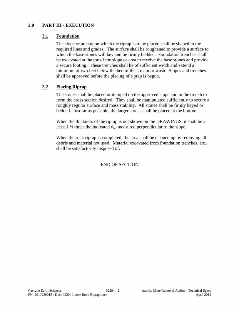
Cascade Earth Sciences 02204 - 2 Azurite Mine Removal Action – Technical Specs PN: 2010230015 / Doc: 02204 Loose Rock Riprap.docx April 2011
3.0 PART III - EXECUTION
3.1 Foundation
The slope or area upon which the riprap is to be placed shall be shaped to the required lines and grades. The surface shall be roughened to provide a surface to which the base stones will key and be firmly bedded. Foundation trenches shall be excavated at the toe of the slope or area to receive the base stones and provide a secure footing. These trenches shall be of sufficient width and extend a minimum of two feet below the bed of the stream or wash. Slopes and trenches shall be approved before the placing of riprap is begun.
3.2 Placing Riprap
The stones shall be placed or dumped on the approved slope and in the trench to form the cross section desired. They shall be manipulated sufficiently to secure a roughly regular surface and mass stability. All stones shall be firmly keyed or bedded. Insofar as possible, the larger stones shall be placed at the bottom.
When the thickness of the riprap is not shown on the DRAWINGS, it shall be at least 1 ½ times the indicated d50 measured perpendicular to the slope. When the rock riprap is completed, the area shall be cleaned up by removing all debris and material not used. Material excavated from foundation trenches, etc., shall be satisfactorily disposed of.
END OF SECTION

Cascade Earth Sciences 02220 - 1 Azurite Mine Removal Action – Technical Specs PN: 2010230015 / Doc: 02220 Excavation and Embankment.docx April 2011
DIVISION 02
SECTION 02220 EXCAVATION AND EMBANKMENT
1.0 PART I - GENERAL
1.1 Description
This item shall consist of excavation and shaping of roadways, and filling of subsidences, borrow excavation, drainage excavation, shaping of stream channels, removal of slide material, excavation of unsuitable material, embankment construction, and disposal of all excavated material necessary for the completion of construction including roadway ditches, channel changes, furrows, slope rounding, benches, berms, dips, approaches, and subsidiary work.
1.2 Excavation
Excavation shall consist of the excavation and disposal of all excavated material at designated locations, regardless of its nature, that is not included under other pay items listed in the Schedule of Items.
1.3 Borrow Excavation
Borrow excavation shall consist of the excavation and utilization of material from sources shown on the DRAWINGS or from commercial sources. Additional sources of borrow excavation shall be approved in advance by the CONTRACTING OFFICER.
1.4 Method of Measurement
The method of measurement will be designated in the schedule of items and measured in accordance with Section 00100.
The measurement of excavation will include:
Construction excavation
Rock and unsuitable material below the required grade and unsuitable material beneath embankment areas
Furrow ditches outside the roadway, except when furrow ditches are included in the Schedule of Items
Topsoil and other material removed and stockpiled as directed
Borrow material used in the work, except when borrow is included in the Schedule of Items
The volume of conserved materials taken from stockpiles and used in the WORK.
Slide material not attributable to negligence of the CONTRACTOR.
Developing and/or reshaping stream channels.

Cascade Earth Sciences 02220 - 2 Azurite Mine Removal Action – Technical Specs PN: 2010230015 / Doc: 02220 Excavation and Embankment.docx April 2011
The measurement of excavation will not include the following:
Material used for other than approved purposes.
Unauthorized excavation or borrow.
Quantity of material excavated from slope rounding.
Overbreakage from the backslope in rock excavation requiring blasting.
Material scarified in place to receive the first layer of embankment.
Benching or stepping existing ground for embankment foundation.
Stepping or scaling cut slopes. When designed quantities are designated in the Schedule of Items as the method of measurement, the original design data has been established on the basis of the undisturbed ground surface elevations. When staked quantities are shown in the Schedule of Items, excavation quantities will be determined by the average end area method using slope stake information taken prior to construction. When actual quantities are designated in the Schedule of Items as the method of measurement, preliminary cross sections or comparable measurements will be taken of the undisturbed ground surface and quantities finally measured in accordance with the following.
When excavation is designated as a pay item in the Schedule of Items, final cross sections or comparable measurements will be taken of the completed and accepted work.
When embankment is designated as a pay item in the Schedule of Items, measurement will be in the final position.
When borrow is designated as a pay item in the Schedule of Items, measurement will be in the original position.
1.5 Basis of Payment
The accepted quantities will be paid at the contract unit price for each Pay Item shown in the Section 00100.
2.0 PART II - PRODUCTS
2.1 Drainage Gravel
Drainage gravel to meet Washington State Department of Transportation, 2006 Standard Specifications 9-03.12 (4) – Gravel Backfill for Drains or the following: Drainage gravel shall consist of crushed, processed, or naturally occurring granular material. It shall be free from various types of wood waste or other extraneous or objectionable materials. It shall have such characteristics of size and

Cascade Earth Sciences 02220 - 3 Azurite Mine Removal Action – Technical Specs PN: 2010230015 / Doc: 02220 Excavation and Embankment.docx April 2011
shape that it will compact and shall meet the following specifications for grading and quality:
Sieve Size Percent Passing 1″ square 100 - — 3⁄4″ square 80-100 3⁄8″ square 0-40 U.S. No. 4 0-4 U.S. No. 200 0-2
All percentages are by weight.
2.2 Base Material
Base Material shall consist of granular material, either naturally occurring or processed. It shall be essentially free from various types of wood waste or other extraneous or objectionable materials. It shall have such characteristics of size and shape that it will compact readily and shall meet the following test requirements: Stabilometer “R” Value 72 min. Swell pressure 0.3 psi max. The maximum particle size shall not exceed 2/3 of the depth of the layer being placed. Base material shall meet the following requirements for grading and quality when placed in hauling vehicles for delivery to the roadway or during manufacture and placement into a temporary stockpile. The exact point of acceptance will be determined by the ENGINEER.
Sieve Size Percent Passing 2″ square 75-100 U.S. No. 4 22-100 U.S. No. 200 0-10
Dust Ratio: 2⁄3 max. Sand Equivalent 30 min.
All percentages are by weight. Gravel base material retained on a U.S. No. 4 sieve shall contain not more than 0.20 percent by weight of wood waste.
2.3 Wasterock
Shall be unclassified material excavated from the upper wasterock pile and the lower wasterock pile as directed by the ENGINEER and indicated on the DRAWINGS.

Cascade Earth Sciences 02220 - 4 Azurite Mine Removal Action – Technical Specs PN: 2010230015 / Doc: 02220 Excavation and Embankment.docx April 2011
2.4 Soil Cushion
Shall be a fine grained soil with a maximum particle size of ½ inch and 80% passing the #60 sieve (0.25mm)
2.5 Talus
Shall be loose rock taken from the site as directed by the ENGINEER. 3.0 PART III – EXECUTION
3.1 Clearing and Grubbing
Clearing and grubbing shall be accomplished in accordance with Section 02130 before work under Section 02220 begins, except the grubbing of stumps, which may proceed concurrently with excavation, and the burning of slash, which may be delayed until weather permits. Excavation and placement operations shall be conducted so material to be treated under Section 02130 will not be incorporated in the roadway.
3.2 Pioneering
Pioneering operations for the top of excavation slopes, toe of embankments, or pioneer road construction shall prevent undercutting of the final excavation slope, depositing of materials outside of the construction limits, and any restriction of drainage.
3.3 Utilization of Excavated Materials
All suitable, excavated material shall be used in the construction of embankments, subgrades, shoulders, slopes, bedding, and backfill for subsidences and for other purposes as shown on the DRAWINGS.
3.3.1 Excess Excavation
Designed excess excavation shall be disposed of as shown on the DRAWINGS.
3.3.2 Rock for Slope Protection
Excavated rock suitable for protection of embankments or backfill of subsidences may be conserved and used in lieu of a designated materials source.
3.3.3 Conserving Material
Material encountered in the excavation, suitable for cushion, finishing, topsoil, or other purposes, may be conserved and utilized instead of materials from designated sources. Excessively wet material that is otherwise suitable for embankment or fill shall be field drained and dried before placement.
Cascade Earth Sciences 02220 - 5 Azurite Mine Removal Action – Technical Specs PN: 2010230015 / Doc: 02220 Excavation and Embankment.docx April 2011
3.3.4 Excavation of Unsuitable Material
Unsuitable material shall be excavated. Disposal will be as shown on the DRAWINGS. Excavated areas shall be backfilled with suitable material when necessary to complete the work. Frozen material shall not be placed in embankments. Rocks that are too large to be incorporated into the embankment shall be broken for incorporation, maneuvered to the face of the embankment, and embedded so that they will not roll or obstruct the use and maintenance of the roadbed, or moved to approved locations.
3.3.5 Conservation of Topsoil
When shown on the DRAWINGS, suitable topsoil shall be removed, transported, and deposited in the designated stockpile areas.
3.4 Drainage Excavation
Drainage excavation shall include construction of side ditches, minor channel changes, inlet and outlet ditches, furrow ditches, ditches constructed along roads but beyond the roadway limits, subsidence areas, and other minor earth drainage structures as shown on the DRAWINGS. Excavated material shall be utilized in accordance with paragraph 3.03.
3.5 Finishing Roadbed
Rock requiring blasting, rippable rock, and boulders shall be excavated to a minimum depth of six inches below subgrade unless otherwise shown on the DRAWINGS, and replaced with suitable cushion material obtained from within the construction limits or from sources shown on the DRAWINGS. Undrained pockets in a rock surface, within the limits of the roadbed, shall be excavated to properly drain or be filled with approved impermeable material. For facilities receiving base or surface course, rocks larger than four inches that do not protrude above the subgrade more than one-third of the depth of the base or surface course, or three inches, whichever is less, may be left in place. For unsurfaced facilities, unless other wise shown on the drawings, the top four inches below the finished surface shall consist of cushion material containing rocks less than four inches in greatest dimension that are developed by scarification, rolling, or importing suitable material obtained from sources shown on the drawings. The subgrade shall be shaped, dressed, and compacted when required. Low sections, holes, or depressions shall be brought to grade with suitable material.
3.6 Finishing Slopes
Finished slopes shall conform reasonably to the lines staked on the ground or shown on the DRAWINGS. The finished slope shall be left in a roughened condition to facilitate the establishment of vegetative growth. The finish associated with template and stringline or handraking methods will not be

Cascade Earth Sciences 02220 - 6 Azurite Mine Removal Action – Technical Specs PN: 2010230015 / Doc: 02220 Excavation and Embankment.docx April 2011
permitted. Loose rock, debris, and other material larger than six inches in diameter shall be removed from the slope. The tops of excavations, excluding areas of solid rock, shall be blended with the adjacent terrain by rounding where shown on the DRAWINGS. Decomposed rock that may be cut without blasting or ripping shall be rounded. Earth overlying rock shall be rounded above the rock. All rock excavations that require blasting shall be formed with controlled blasting techniques unless otherwise shown on the DRAWINGS. Controlled blasting is defined as the controlled usage of explosives and blasting accessories in appropriately alined and spaced drill holes for the purpose of producing a free surface or shear plane in the rock excavation slopes and of minimizing landscape damage, adjacent ground vibration and overbreak. Presplitting is not intended unless shown on the drawings. The CONTRACTOR shall drill, blast, and excavate short test sections (not to yield in excess of 1,000 cubic yards) to determine the controlled blasting method, hole spacing, and charge best suited to the material encountered.
3.7 Overbuilding and Landscape and Stream Protection
Excavated or embankment material shall be confined within the construction limits to avoid overbuilding and to protect the landscape and streams.
3.8 Subgrade Treatments
Subgrade treatment shall consist of soil modification by admixing aggregates, placing filter cloth, fiber mat, wood corduroy, rock blanket, or other similar materials over areas of unsuitable embankment material that are shown on the DRAWINGS. The construction and material requirements for the type of subgrade treatment will be specified or shown on the DRAWINGS.
3.9 Earth Berms
Permanent earth berms shall be constructed along the shoulder of roads or streams at locations shown on the DRAWINGS. Material used in the construction of berms shall be well graded with no rocks having a diameter greater than one-fourth of the height of the berm. Acceptable material for the berm may be windrowed as the roadbed is constructed or stockpiled at a designated area as specified by the CONTRACTING OFFICER for later use. When the local material is not acceptable, material shall be imported from approved locations or from commercial sources. Material used for berm construction shall contain no frozen material, roots, sod, or other deleterious material. Material shall not be wasted over the embankment slope. Compaction density of the berm shall be 90% of the maximum density as determined by AASHTO T-99, Method C or D. Compaction equipment shall be capable of obtaining compaction requirements without detrimentally affecting the

Cascade Earth Sciences 02220 - 7 Azurite Mine Removal Action – Technical Specs PN: 2010230015 / Doc: 02220 Excavation and Embankment.docx April 2011
compacted material. The compaction units may be of any type, provided they are capable of compacting each lift of material as specified. Maximum lift will be 12 inches.
3.10 Stream Channel Construction
This work entails the excavation and/or shaping of stream channels as shown on the DRAWINGS. All construction of the channel will conform to all grades, bank slopes, etc., as specified on the DRAWINGS or in other Sections of this Contract. Under no circumstances is coal, gob, or toxic susbstances to be included in this work. Should coal, gob, or toxic substances be encountered during excavation, the CONTRACTOR will notify the CONTRACTING OFFICER immediately. Basically, if coal, gob, or toxic substances are encountered, the CONTRACTOR will over excavate the channel by three feet, place protective liners as specified in other Sections of this Contract, and haul in suitable fill material to bring the centerline of the channel back up to the desired grade. The CONTRACTING OFFICER will determine the quantities involved for Contract price adjustments for this work. Excavation of the channels will be paid under this Section and according to the units shown in the Schedule of Items. Channel protective measures, such as liners, riprap, etc., will be paid for under other Sections of this Contract.
3.11 Water
Water sources and access are shown on the DRAWINGS. If the CONTRACTOR elects to obtain water from other sources, the CONTRACTOR shall be responsible for obtaining the right to use the water including any royalty costs. Mobile watering equipment shall have reasonable watertight tanks of known capacity. Equipment used for dust control and finishing operations of subgrade and surfaces shall provide uniform and controlled application of water without ponding or washing. Positive control of water from the driver's position is required at all times. Payment for furnishing, hauling, and applying water shall be included in the contract unit price for this specification.
3.12 Embankment and Backfill Placing Methods
A. All Methods - When an embankment or backfill is to be placed across swampy ground or a swampy subsidence and removal of unsuitable material or subgrade treatment is not required, the lower part of the embankment or backfill shall be constructed in a single layer to the minimum depth necessary to support construction equipment or subsequent backfill material. Rocks larger than six-inch diameter shall not be concentrated in any areas of the embankment or backfill.
B. Specific Methods - All embankments or backfill shall be placed by one or
more of the following methods as shown on the DRAWINGS and listed in the schedule of items:

Cascade Earth Sciences 02220 - 8 Azurite Mine Removal Action – Technical Specs PN: 2010230015 / Doc: 02220 Excavation and Embankment.docx April 2011
Method 1 - Side Casting and End Dumping. Embankment or backfill may be placed by side casting and end dumping. Where material containing a large amount of rock is used to construct embankments or backfill, a solid embankment or base for additional backfill material shall be provided by working smaller rocks and fines in with the larger rocks and fines to fill the voids. Method 2 - Layer Placement. Surfaces steeper than a ratio of three to one, upon which embankment is to be placed, shall be roughened or stepped when shown on the drawings to provide permanent bonding of new and old materials. Embankment or backfill shall be layer placed, except over rock surfaces, in which case material may be placed by end dumping to the minimum depth needed for operation of spreading equipment. Each embankment or backfill layer shall be leveled and smoothed before placement of subsequent layers. Hauling and spreading equipment shall be operated uniformly over the full width of each layer. Suitable material shall be placed in layers no more than 12 inches thick, except when the material contains rock more than nine inches in diameter, in which case layers may be of sufficient thickness to accommodate the material involved. No layer shall exceed 24 inches before compaction. Placing individual rocks or boulders greater than 24 inches will be permitted provided the embankment or backfill will accommodate them. Such rocks and boulders shall be at least six inches below subgrade. They shall be carefully distributed and the voids filled with finer material to form a dense and compacted mass. Where material containing large amounts of rock is used to construct embankments or backfills, the layers may be of sufficient thickness to accommodate the material involved. A solid embankment or backfill with compaction to at least 90% of maximimum density as determined by ASTM D698 or as approved by the ENGINEER shall be constructed by working smaller rock and fines in with the larger rocks to fill the voids and by operating hauling and spreading equipment uniformly over the full width of each layer as the embankment or backfill is constructed. Method 3 - Controlled Compaction. Embankments or backfills shall be placed as specified in Method 2, except earth embankment or backfill shall be placed in horizontal layers not exceeding eight inches (loose measure) and compacted. Material shall be at a moisture content suitable for attaining the required compaction. Embankments and backfills and the top one foot of excavation sections shall be compacted to at least 95 percent of the maximum density as determined by AASHTO T 99, Method C or D.

Cascade Earth Sciences 02220 - 9 Azurite Mine Removal Action – Technical Specs PN: 2010230015 / Doc: 02220 Excavation and Embankment.docx April 2011
The density of the embankment or backfill material will be determined during the progress of the WORK in accordance with AASHTO T 191, T 205, and T 217; or T 238, and T 239. Corrections for coarse particles will be made in accordance with AASHTO T 114. Density requirements will not apply to portions of rock embankments or backfills that cannot be tested in accordance with approved methods. When this condition exists, compaction shall be provided by working smaller rock and fines in with the larger rocks to fill the voids and by operating equipment over the embankment materials.
3.13 Construction Tolerances
The tolerance class shall be as shown on the DRAWINGS. Roadway ditches shall be constructed to flow in the direction of design with the gradient no flatter than one-half of one percent.
Tolerance Classa
Tolerance Classa Item A B C D E F Roadbed Width (Feet) +/- 0.5 +/- 1 +/- 1 +/- 1 +/- 1 +/- 2 Subgrade Elevation (Feet) +/- 0.1 +/- 0.2 +/- 0.5 +/- 1 +/- 2 +/- 3 Centerline Alignment (Feet) 0.2 0 .5 1 1 2 3 Slopes, Excavation, Embankment, Backfill (Percent)
+/- 3 +/- 5 +/- 5 +/- 5 +/- 10 +/- 10
aMaximum allowable deviation from construction stakes and DRAWINGS.
Deviations shall be uniform in the direction of change for a distance of 200 feet or more along the project centerline.
3.14 Grading Plans
Cross sections and grading plans are provided on the DRAWINGS. The CONTRACTOR shall be held to fixed elevations, as determined by a registered surveyor. Proposed channels shall be construction staked by a registered surveyor and subsequent re-staking shall be included based on field adjustment made by the CONTRACTING OFFICER. A verification survey by a registered surveyor shall be completed and submitted to the CONTRACTING OFFICER for approval at the end of the project. All costs shall be included in a separate line item if survey work is required for the completion of the project. A smooth and finish-graded surface shall be required on all areas before placing topsoil.
3.15 Positive Drainage
The CONTRACTOR shall provide positive drainage for all areas during and after construction. No water should be impounded during or after construction. All areas which settle below plan elevation or impounded water before completion of the Contract shall be filled in, regraded, and reseeded.

Cascade Earth Sciences 02220 - 10 Azurite Mine Removal Action – Technical Specs PN: 2010230015 / Doc: 02220 Excavation and Embankment.docx April 2011
3.16 Erosion Control
The CONTRACTOR shall be responsible for the repair of slope erosion up to the final acceptance of the project. In areas not designated for sheet runoff, the CONTRACTOR shall make an attempt to grade the embankment to drain into existing or proposed swale areas. This shall include the use of diversion swales and other measures to direct runoff to rock dams, rock channels, etc.
All drainage swales and ditches must be approved by the CONTRACTING OFFICER prior to placing topsoil and reseeding. The cost of the swales and ditches, if not already in a separate line item, shall be included with the line item for placeing of embankments or fill.
3.17 Wasterock Repository
The repository shall be built by placing material in maximum 8-inch loose lifts at near optimum moisture and compacted to 90% maximum dry density as determined by ASTM D-698. Maximum thickness of the completed repository shall be 25 feet, exclusive of cover material
END OF SECTION

Cascade Earth Sciences 02228 - 1 Azurite Mine Removal Action – Technical Specs PN: 2010230015 / Doc: 02228 Culvert Pipe Arches.docx April 2011
DIVISION 02
SECTION 02228 CULVERT PIPE AND PIPE ARCHES
1.0 PART I – GENERAL
1.1 Description
This WORK shall consist of furnishing and installing, or installing only, metal pipe and pipe appurtenances, including all excavation, bedding, and backfilling required to complete the WORK.
1.2 Method of Measurement
Culvert pipe and pipe arches will be measured by the actual number of linear feet of the kind, class or shape, and the several sizes and metal thickness, bedded, backfilled, and accepted in place. When ends of a round pipe culvert are cut on a skew or slope, measurement will be the average of the top and bottom centerline lengths. When ends of a pipe arch culvert are cut on a slope, measurement will be the bottom centerline length.
Metal end sections, elbows, and branch connections shall be measured separately as "Each" under this Section.
2.0 PART II – PRODUCTS
2.1 Corrugated Iron or Steel Pipe and Pipe Arches
A. Riveted Pipe and Pipe Arches - These pipes shall meet the requirements of AASHTO M 36.
B. Welded Pipe and Pipe Arches - Corrugated metal pipe and pipe arches
fabricated by resistance spot welding shall meet the applicable requirements of AASHTO M 36.
C. Helical Pipe - Unperforated helically corrugated pipe with continuous lock or
welded seams shall meet the applicable requirements of AASHTO M 36. D. Coupling Bands - Coupling bands shall meet the requirements of AASHTO
M 36. E. Special Sections - Special sections such as elbows, tees, wyes, etc., shall be
the same thickness as the conduit to which they are joined and meet the applicable requirements of AASHTO M 36.
F. Flared End Sections - Flared end sections for inlet and outlet ends of pipe
and pipe arch culverts shall meet the applicable requirements of AASHTO M 36. End sections shall be fabricated in accordance with the details and dimensions shown on the DRAWINGS, except minor variations may be

Cascade Earth Sciences 02228 - 2 Azurite Mine Removal Action – Technical Specs PN: 2010230015 / Doc: 02228 Culvert Pipe Arches.docx April 2011
accepted to permit the use of the manufacturer's standard methods of fabrication.
2.2 Bituminous Coated Corrugated Iron or Steel Pipe and Pipe Arches
These conduits and their coupling bands shall meet the requirements of AASHTO M 190. The coating shall be Type A, B, C, or D as specified. Coupling bands shall be fully coated with bituminous material. Special sections, such as elbows and prefabricated flared end sections, shall meet the applicable requirements of AASHTO M 190. Coating and invert paving shall be of the type specified. Flared end sections shall meet the requirements of AASHTO M 243 or M 190 for the coating specified. The CONTRACTING OFFICER may waive the imperviousness test for coated pipe if no separation of coating from metal is observed.
2.3 Polymeric Precoated Steel Pipe, Pipe Arches, and Underdrains
A. Pipe shall meet the requirements of AASHTO M 245 B. Coupling bands shall meet the requirements of AASHTO M 245 C. Special sections such as elbows, tee, wyes, etc., shall be the same thickness as
the conduit to which they are joined. D. Flared end sections for attachment to the inlet and outlet ends of pipe and pipe
arch culverts shall meet the applicable requirements of AASHTO M 243 and M 246. End sections shall be fabricated in accordance with the details and dimensions shown on the DRAWINGS, except that minor variations may be accepted to permit the use of the manufacturer's standard methods of fabrication.
2.4 Corrugated Iron or Steel Pipe for Underdrains, Plain Galvanized or
Precoated
Plain galvanized pipe shall meet the requirements of AASHTO M 36. Precoated underdrains shall meet the requirements of AASHTO M 245.
2.5 Bituminous Coated Iron or Steel Pipe for Underdrains
Pipe shall meet the requirements of AASHTO M 36 and shall be coated with bituminous material to meet the requirements of AASHTO M 190, Type A coating, except that minimum coating thickness shall be 0.03 inch. Coupling bands shall be fully coated. The specified minimum diameter of perforations shall apply after coating. The CONTRACTING OFFICER may waive the imperviousness test if no separation of coating from metal is observed.
2.6 Corrugated Aluminum Alloy Culvert Pipe and Pipe Arches
Pipe shall meet the requirements of AASHTO M 196.

Cascade Earth Sciences 02228 - 3 Azurite Mine Removal Action – Technical Specs PN: 2010230015 / Doc: 02228 Culvert Pipe Arches.docx April 2011
2.7 Corrugated Aluminum Alloy Pipe for Underdrains
Pipe shall meet the requirements of AASHTO M 196.
2.8 Bituminous Coated Corrugated Aluminum Alloy Culvert Pipe and Pipe Arches
Pipe shall meet the requirements of AASHTO T 196 and shall be coated with bituminous material meeting the requirements of AASHTO M 190. Coating and invert paving shall be of the type specified.
2.9 Bituminous Coated Corrugated Aluminum Alloy Pipe Underdrains
Pipe shall meet the requirements of AASHTO M 196 and shall be coated with bituminous material meeting the requirements of AASHTO M 190.
2.10 Structural Plate for Pipe, Pipe Arches, and Arches
The pipes and bolts and nuts for connecting plates shall meet the requirements of AASHTO M 167.
2.11 Full Bituminous Coated Structural Plate Pipe, Pipe Arches, and Arches
Pipes shall meet the requirements of AASHTO M 167 and shall be coated with bituminous material meeting the requirements of AASHTO M 243.
2.12 Aluminum Alloy Structural Plate for Pipe, Pipe Arches, and Arches
Pipes and the bolts and nuts for connecting plates shall meet the requirements of AASHTO M 219.
2.13 Aluminum Coated (Aluminized Type 2) Corrugated Steel Pipe and Pipe
Arches
A. Pipe and coupling bands shall meet the requirements of AASHTO M 36 except that they shall be made from material meeting the requirements of AASHTO M 274.
B. Special sections such as elbows, tee, wyes, etc., shall be the same thickness as
the conduit to which they are joined and shall meet the applicable requirements of AASHTO M 36 and M 274.
Bedding and backfill material shall meet the requirements of paragraph 3.08. Damaged spelter coating caused by welding, field cutting, or mishandling shall be cleaned and painted as specified in AASHTO M 36. End sections shall be constructed of a material meeting the requirements of AASHTO M 218 or AASHTO M 196. Bituminous coated end sections shall be coated to meet the requirements of AASHTO M 243 or AASHTO M 190.

Cascade Earth Sciences 02228 - 4 Azurite Mine Removal Action – Technical Specs PN: 2010230015 / Doc: 02228 Culvert Pipe Arches.docx April 2011
The materials used in each pipe installation shall be compatible with each other to prevent electrolysis or physical failure. Either annular or helical pipe corrugations will be acceptable, but each pipe installation shall consist of only one class of corrugation. The lengths and locations of individual pipe shown on the DRAWINGS are approximate. Pipe should not be ordered until culvert locations are designated on the ground and a written list of the correct lengths is issued by the CONTRACTING OFFICER.
3.0 PART III – EXECUTION
3.1 Water Pollution and Stream Degradation
Water Pollution and stream degradation shall be controlled.
Pipe which is installed in or which will affect streams that are designated as important fisheries shall be installed only during those periods shown on the DRAWINGS or in Special Project Specifications.
3.2 Excavation
Excavation for culverts shall be to the lines and grades or elevations shown on the DRAWINGS or as designated on the ground. Excavations shall be of sufficient size to permit the placing and backfilling of culverts. Boulders, logs, and any other unsuitable materials encountered shall be removed and disposed of in areas designated on the DRAWINGS. The width of trenches shall permit satisfactory jointing and thorough tamping of the bedding material under and around the culvert.
Unsuitable foundation material shall be excavated below the invert of the culvert to an approximate depth of two feet and a width of at least the culvert diameter plus four feet. Unsuitable material shall be replaced with selected granular foundation material and compacted in accordance with paragraph 3.08.
Where rock, hardpan, or other unyielding material is encountered, it shall be removed below the foundation grade for a depth of at least one foot. The width of the excavation shall be at least two feet greater than outside width of the culvert. This excavated material shall be replaced with selected granular foundation material and compacted in accordance with paragraph 3.08.
3.3 Utilization of Excavated Materials
All suitable excavated material shall be utilized as backfill or embankment. No excavated material shall be placed in live streams. All surplus material shall be disposed of as shown on the DRAWINGS. No excavated material shall be deposited in a manner that will endanger the partly finished structure.

Cascade Earth Sciences 02228 - 5 Azurite Mine Removal Action – Technical Specs PN: 2010230015 / Doc: 02228 Culvert Pipe Arches.docx April 2011
3.4 Bedding
Bedding shall consist of bedding the pipe to a depth of not less than 10 percent of its total height. The foundation surface, after excavation in accordance with paragraph 3.02, shall be compacted in accordance with paragraph 3.08 and shaped to fit the pipe. The completed bedding shall have a longitudinal camber when shown on the DRAWINGS. The bedding material shall be selected mineral soil meeting the requirements for backfill in paragraph 3.08.
3.5 Laying Pipe
No pipe shall be placed in service until a suitable outlet is provided.
Paved or partially lined pipe shall be laid so the longitudinal centerline of the paved segment coincides with the flowline. Elliptical pipe shall be placed with the major axis within five degrees of a vertical plane through the longitudinal axis of the pipe. The final installed alignment of all pipe shall have no sag and no point shall vary from a straight line drawn from inlet to outlet by more than two percent horizontally and vertically of the culvert length or one foot, whichever is less, unless otherwise shown on the DRAWINGS. Helically corrugated lock-seam pipe shall be installed with the seam at the inlet end placed below the horizontal centerline. Longitudinal laps on riveted or spot-welded pipe shall be positioned at any location between 45 degrees above or below horizontal.
3.6 Joining Pipes
Pipe shall be firmly joined by form-fitting coupling bands. End sections shall be attached to pipe by connecting bands or other means as recommended by the manufacturer. Rubber gaskets shall be installed at each joint to form a watertight connection when shown on the DRAWINGS. Dimpled bands shall not be used when the slope of the pipe is greater than 25 percent. The coupling bands shall meet the strength requirements of field joints for Non-Erodible Soil Condition--Special Joint Type according to Division 2, Section 23 of the "Standard Specification for Highway Bridges" by AASHTO.
3.7 Shop Elongation
When shown on the DRAWINGS, the vertical diameter of round pipe shall be increased five percent by shop elongation.

Cascade Earth Sciences 02228 - 6 Azurite Mine Removal Action – Technical Specs PN: 2010230015 / Doc: 02228 Culvert Pipe Arches.docx April 2011
3.8 Backfilling
Pipe meeting any of the following conditions shall not be placed or back-filled until the excavation and foundation have been approved by the CONTRACTING OFFICER:
A. Embankment height greater than 10 feet at subgrade centerline B. Installation in a live stream C. Round pipe with a diameter of 48 inches or greater D. Pipe arches with a span of 50 inches or greater
After the bedding is prepared and the pipe is placed, selected material shall be placed in layers not exceeding six inches loose thickness and compacted under the haunches and alongside the pipe. The material shall have the moisture content needed for effective compacting. Backfill shall be readily compactible material free of frozen lumps, chunks of highly plastic clay, or other objectionable material. Rocks larger than three inches in diameter shall not be used within one foot of the pipe. On each side of the pipe there shall be an area of compacted material at least as wide as two diameters of the pipe or 12 feet, whichever is less. Backfill shall be compacted without damaging or displacing the pipe. The density shall be that of the surrounding embankment or 95 percent of the maximum density as determined by AASHTO T 99 Method C or D, whichever is greater. Backfilling and compacting shall be continued until the backfill is 12 inches above the top of the culvert. After being bedded and backfilled pipe shall be protected by an adequate cover of embankment before heavy equipment is permitted to cross during roadway construction. Pipe distorted more than five percent of nominal dimension, ruptured, or broken shall be replaced.
4.0 PART IV – MEASUREMENT AND PAYMENT
Culvert pipe shall be paid for as indicated in the Pay Items listed in Section 00100.
END OF SECTION

Cascade Earth Sciences 02251 - 1 Azurite Mine Removal Action – Technical Specs PN: 2010230015 / Doc: 02251 Sediment Control.docx April 2011
DIVISION 02
SECTION 02251 SEDIMENT CONTROL
1.0 PART I - GENERAL
1.1 General
Short-term sediment collection for construction activities.
1.2 Submittals
A. Submit manufacturer’s certification that sediment collection systems meet or exceed specified requirements.
B. Submit manufacturer’s installation instructions and maintain copy at the
jobsite.
1.3 Delivery, Storage and Handling
A. Unload, store and load sediment collection materials in a manner which prevents damage or excessive exposure to sunlight and weather.
2.0 PART II - PRODUCTS
2.1 Erosion and Sediment Control Systems
A. Comply with type of sediment collection systems indicated in the Contract Documents.
B. If sediment collection systems are not specified, use any of the alternate
materials meeting the minimum requirements of this section and the approved Erosion Control Plan.
C. Notify the ENGINEER if installation conditions do not match those in the
DRAWINGS. D. Provide sediment collection materials and use in accordance with the
governing agency.
2.2 Inlet Protection
A. Provide a filtering system around an inlet or drain to trap sediment and prevent the sediment from entering the storm drain system in accordance with the STANDARD DRAWINGS.

Cascade Earth Sciences 02251 - 2 Azurite Mine Removal Action – Technical Specs PN: 2010230015 / Doc: 02251 Sediment Control.docx April 2011
B. Filter Fabric Inlet Protection:
1. Filter Fabric: Refer to specifications for Silt Fence. 2. Wooden Stakes: 2 inches x 2 inches or 2 inches x 4 inches with a
minimum length of 3.0 feet. 3. Staples: Heavy-duty wire at least 3/8 inches long. 4. Washed Gravel: ¾ inches to 1-1/4 inches in diameter, with less than 5%
fines.
C. Gravel Inlet Protection:
1. Mesh: hardware cloth or wire mesh with 3/8 inch to ½ inch openings. 2. Filter Fabric: Refer to specifications for Silt Fence. 3. Washed Gravel: ¾ inch to 4 inches is diameter.
D. Block and Gravel Inlet Protection:
1. Mesh: Hardware cloth or wire mesh with 3/8 to ½ inch openings. 2. Filter Fabric: Refer to specifications for Silt Fence. 3. Washed Gravel: ¾ inch to 4 inches in diameter.
2.3 Straw Bale Barrier
A. Provide a temporary sediment barrier consisting of a row of entrenched and anchored straw bales in accordance with the DRAWINGS.
B. Bales to be made of densely packed cut straw securely bundled by bailing
twine or wire. The material must be certified as weed-free.
2.4 Temporary Berm
A. Provide a temporary berm or ridge of compacted soil or sandbags, which will intercept and divert runoff from the construction areas.
B. Construct soil berm from embankment materials. C. Construct sandbag berms with high quality sandbags. Each bag to have the
following dimensions: length - 24 inches to 30 inches; width – 16 inches to 20 inches; depth or thickness – six inches to eight inches; and weight – 90 pounds to 130 pounds.
2.5 Sediment Basin
A. Provide a temporary basin to collect, trap, and store sediment produced by construction activities in accordance with the size requirements outlined in Section 3.4.
B. Construct sediment basins using excavation and embankment materials by
either excavating the basin or by placing an earthen embankment across a low

Cascade Earth Sciences 02251 - 3 Azurite Mine Removal Action – Technical Specs PN: 2010230015 / Doc: 02251 Sediment Control.docx April 2011
area or drainage swale. Provide a riser and pipe outlet with a gravel outlet or spillway to slow the release of runoff.
C. Fill material should be taken from approved designated borrow areas, and
should be of the type and quality conforming to that specified for the adjoining fill material. It should be free of roots, woody vegetation, oversize stones, rocks exceeding 6-inch diameter, or other objectionable materials. Do not use frozen material.
2.6 Silt Fence
A. Provide temporary sediment barrier consisting of a filter fabric stretched and attached to supporting posts, with wire fence backing as required by the type of fabric employed as indicated on the DRAWINGS.
B. Silt fences may be made of burlap or various synthetic materials. Acceptable
synthetic materials are pervious polypropylene, nylon, and polyester or polyethylene yarn conforming to the performance specifications listed in Table 1.
Table 1. Silt Fence Performance Specifications
Physical Property Requirement Filtering efficiency 75% to 85% (minimum)
Tensile strength at 20% (maximum) elongation
Standard strength – 360 lbs./ft. (minimum) Extra strength – 600 lbs./ft. (minimum)
Slurry flow rate 0.3 gpm/ft.2 (minimum)
C. Design Life: 6 months for synthetic fences, two months for burlap. D. Wire Reinforced Backing (if used): 14 gage minimum, with mesh spacing and
a width of 2-4 feet. E. Post Specifications:
1. Length: 4 feet minimum. 2. Material: 2 inches x 2 inches or 2 inches x 4 inches pine (or equivalent) or
1.0 pound/foot to 1.3 pound/foot steel.
2.7 Culvert Riser
A. Provide a perforated metal pipe attached to a culvert inlet and extending upward to allowing the inlet area to serve as a temporary sediment trap for the construction area.
B. Provide materials for the culvert riser that are consistent with the culvert upon
which they are attached.

Cascade Earth Sciences 02251 - 4 Azurite Mine Removal Action – Technical Specs PN: 2010230015 / Doc: 02251 Sediment Control.docx April 2011
3.0 PART III - EXECUTION
3.1 Examinations
A. Verify that slope contours are to required alignment and grade. Place sediment collection system on all drainage ways downstream of disturbed areas of construction and as directed by the ENGINEER and as indicated in the CONTRACT DOCUMENTS.
B. Examine sediment collection material and equipment for defect or damage. C. Verify sediment collection material and equipment delivered to site meet the
requirements of the CONTRACT DOCUMENTS. D. Provide sediment collection facilities in accordance with governing agency. E. Install sediment collection systems in accordance with the DRAWINGS.
3.2 Inlet Protection
A. Height of Filter Fabric: Limit height of the filter fabric to 15 inches above the crest of the drop inlet.
B. Sump: Where possible, provide a filter fabric or block-and-gravel protection
device with a sediment-trapping sump 12 inches to 18 inches deep as measured from the crest of the inlet. Side slopes should be 2:1. Provide 30 cubic yards of excavation for each acre of ground disturbed.
C. Orientation: Place the longest dimension of the basin toward the area of
greatest flow. D. Filter fabric:
1. Stakes: Place a stake at each corner of the inlet and around the edges at no
more that 3 feet apart. Drive the stakes into the ground, if possible, or a minimum of 8 inches.
2. Frame: For stability, install a framework of wood strips around the stakes
at the crest of the overflow area, 18 inches above the crest of the drop inlet.
3. Excavate: Excavate a trench eight inches to 12 inches deep around the
outside perimeter of the stakes. If a sediment-trapping sump is being provided, then the excavation may be as deep as 24 inches.
4. Staple: Staple the filter fabric to the wooden stakes with heavy-duty
staples, overlapping the joints to the next stake. Ensure that 12 inches to 30 inches of filter fabric extends at the bottom so it can be formed into the trench.

Cascade Earth Sciences 02251 - 5 Azurite Mine Removal Action – Technical Specs PN: 2010230015 / Doc: 02251 Sediment Control.docx April 2011
5. Completion: Place the bottom of the fabric in the trench and backfill the trench all the way around, using washed gravel to minimum depth of four inches. Use enough gravel to ensure contact between the filter fabric and the underlying surface.
E. Gravel and Mesh:
1. Preparation: Remove any obstructions to excavating and grading. Excavate sump area, grade slopes, and properly dispose of soil.
2. Secure Inlet: Prevent seepage of sediment-laden-water. 3. Wire Mesh: Place wire mesh over the drop inlet so the wire extends a
minimum of 12 inches beyond each side of the inlet structure. Overlap the strips of mesh if more than one is necessary.
4. Fabric: Place filter fabric over the mesh, extending it at least 18 inches
beyond the inlet opening on all sides. Ensure that weep holes in the inlet structure are protected by filter fabric and gravel.
5. Stone: Place stone or gravel over the fabric/wire mesh to a depth of at least
12 inches.
F. Block and Gravel
1. Preparation: Secure the inlet grate to prevent seepage of sediment-laden water.
2. Wire Mesh: Place wire mesh over the drop inlet so the wire extends a
minimum of 12 to 18 inches. Overlap the strips of mesh if more than one is necessary.
3. Fabric: Place filter fabric (optional) over the mesh and extend it at lease 18
inches beyond the inlet structure. 4. Blocks: Place concrete blocks over the filter fabric in a single row
lengthwise on their sides along the sides on the inlet. Excavate the foundation a minimum of 2 inches below the crest of the inlet. The bottom row of blocks should be against the edge of the structure for lateral support.
5. Orientation: The open ends of the block should face outward, not upward,
and the ends of adjacent blocks should abut. Lay one block on each side o the structure on its side to allow for dewatering of the pool.
6. Dimensions: The block barrier should be at least 12 inches high and may
be up to a maximum of 24 inches high. It may be from 4 inches to 12 inches deep, depending on the size of block used.

Cascade Earth Sciences 02251 - 6 Azurite Mine Removal Action – Technical Specs PN: 2010230015 / Doc: 02251 Sediment Control.docx April 2011
7. Finishing: Prior to backfilling, place wire mesh over the outside vertical end of the blocks so that stone does not wash down the inlet.
8. Gravel: Place gravel against the wire mesh to the top of the blocks.
G. Inspect regularly and after every storm. Make any repairs necessary to ensure
the sediment control device is in good working order. H. Remove accumulated sediment and restore the trap to its original dimensions
when sediment has accumulated to half the design depth of the trap. Sediment should be disposed at an approved site in a manner that will not contribute to additional siltation.
1. Gravel-and-Mesh Devices: Clean (or remove and replace) the stone filter
or filter fabric if it becomes clogged. 2. Filter Fabric Devices: Replace the fabric immediately if it becomes
clogged. Make sure the stakes are firmly in the ground and that the filter fabric continues to be securely anchored.
I. Inlet protection should remain in place and operational until the drainage area
is completely stabilized or up to 30 days after the permanent site stabilization is achieved.
3.3 Straw Bale Barriers
A. Do not use straw bale barriers where flow rate exceed 1 cubic foot/second or the drainage area is greater than 1.25 acres.
B. Provide an undisturbed buffer zone of 3 to 6 feet is necessary between the
barriers and surface waters to allow safe removal of the barrier and of accumulated sediments.
C. Embed bales to a minimum depth of 6 inches and backfill for the entire length
of the barrier. Each bale should be securely anchored with 2 stakes 2 inches x 2 inches x 36 inches or steel drift pins driven at least 18 inches into the ground.
D. Install straw bale barriers at the toe of slopes prior to disturbing the slopes.
Install the bales a short distance away from the toe of the slope and outside of any ditch channel.
E. Place the bales in a single row lengthwise on the contour for sheet flow
applications, or perpendicular to the contour in concentrated flow applications. When flows are expected to be high enough to surpass the infiltration capacity of the bales, the center (low point) bales shall be wrapped in filter fabric with a three foot tail stapled securely and extending from the down gradient side of the barrier to prevent scouring. The ends of the adjacent bales must tightly abut one another.

Cascade Earth Sciences 02251 - 7 Azurite Mine Removal Action – Technical Specs PN: 2010230015 / Doc: 02251 Sediment Control.docx April 2011
F. Fill all gaps between bales with tightly wedged straw. For concentrated flow applications, extend the end of the barrier so that the bottom of the end bales are at a higher elevation than the top of the lowest middle bale to assure that sediment laden water flows through or over the barrier instead of around the ends of the barrier.
G. Perform one inspection during the first runoff-producing event after the
installation of the barriers to assure proper functioning. Immediately repair damaged bales, undercutting, or end runs. Replace bales as needed due to disintegrations or rotting.
H. Remove accumulated sediment and disposed at an approved site in a manner
that will not contribute to additional siltation.
3.4 Temporary Berms
A. Provide berms to prevent minor runoff onto newly constructed slopes until vegetation is established or until permanent measure are in place. Provide berms to intercept flow from the construction area and direct it to sediment removal facilities prior to discharge.
B. Dimensions:
1. Soil Berm: A berm of soil with an approximate height of 12 to 18 inches
with a minimum top width of 24 to 28 inches and side slopes of 2:1 or flatter. Berms should be high enough to prevent flow from overtopping. Berms are normally constructed from embankment materials.
2. Sandbag Berm: Height = 1.5 feet minimum, top width = 1.5 minimum,
bottom width = approximately 4 to 5 feet. 3. Sandbag Size: Length = 24 to 30 inches, depth or thickness = 6 to 8
inches, and weight = 90 to 130 pounds.
C. Construction:
1. Soil Berm: Grade to drain to a slope drain inlet. Construct embankments with a gradual slope to one side of the embankment to permit the placement of all temporary berms and slope drains on one side of the embankment. When fills are constructed on side hill slopes, slope the top surface toward the inside so that surface runoff will be away from the fill slope. Compact the entire width of the berm.
2. Sandbag Berm: Install so that flow under or between bags is prevented.
Stack the sandbags in an interlocking fashion to provide additional strength for resisting the force of the flowing water. However, do not stack them more than three high without broadening the foundation using additional sandbags, or providing additional stability.

Cascade Earth Sciences 02251 - 8 Azurite Mine Removal Action – Technical Specs PN: 2010230015 / Doc: 02251 Sediment Control.docx April 2011
D. Inspect and repair temporary berms periodically as well as after each significance rainfall. For sandbag berms, reshaped or replaced sandbags as needed during inspection. When sediment reaches six inches, remove the accumulated sediment and disposed at an approved site in a manner that will not contribute to additional siltation. Leave berms in place until all upstream areas are stabilized and accumulated sediment has been removed. Remove sandbags by hand.
3.5 Sedimentation Basins
A. Provide sediment basins where physical site conditions or land ownership restrictions preclude the effective use of barrier-type erosion control measures. Provide sediment basins for disturbed areas of more than 10 acres within the same drainage basin or where operations expose critical areas to soil erosion.
B. Volume and Configuration of Basin:
1. Small Areas: Provide at least 65 cubic yards/acre of total drainage area. 2. Larger Areas: For areas greater that 10 acres within the same drainage
basin provide at least 130 cubic yards/acre of total drainage area. 4. Baffles and Spillway: Install baffles or other deflectors to spread the flow
throughout the basin. Install an emergency spillway and riser pipe(s). 5. Depth and Surface Area: Determine the surface area based on the Standard
Drawing with a minimum of three feet of sediment storage and 3:1 side slopes
6. Approval: Submit design of the sediment basin and obtain ENGINEER’S
approval prior to construction.
C. Construction Requirements:
1. Placement: Install the temporary sediment basin before clearing and grading is undertaken. Locate the dam to provide maximum volume capacity for sediment behind the structure. It should not be built within an active stream channel. Install fencing around the basin, as necessary to endure public safety.
2. Preparation: Prepare the dam site by clearing vegetation and removing
topsoil before beginning dam construction. For areas under the embankment and any structural works, lea, grub, strip topsoil to remove all trees, vegetation, roots and other objectionable material. To facilitate clean out and restoration, clear the pool area of all brush, tress or other debris.
3. Spillway Bed: Level the bed for the pipe spillway to provide uniform
support through its entire length under the dam.

Cascade Earth Sciences 02251 - 9 Azurite Mine Removal Action – Technical Specs PN: 2010230015 / Doc: 02251 Sediment Control.docx April 2011
4. Spillway: Construct an emergency spillway on undisturbed soil and not on
fill. Line the spillway with four inches of concrete, reinforced with 6 inch x 6 inch, 6 inch x 6 inch diameter W1.4 each way wire mesh extending to a minimum of 36 inches down each face of the embankment. The spillway should be at lease 18 inches deep with 1:1:5 side slopes.
5. Piping: Secure all pipe joints and fasten watertight. Fasten the riser rigidly
and securely to the barrel and seal watertight. Place the barrel on a firm foundation according to the lines and grades shown on the approved CONTRACT DOCUMENTS.
6. Backfill: Place at least 24 inches of hand-compacted backfill (maximum 6
inch lifts) over the pipe spillway before crossing it with construction equipment. Control the movement of the hauling and spreading equipment over the fill so that the entire surface of each lift will be traversed by not less than one tread tract of the equipment.
7. Discharge: The pipe spillway should discharge at ground elevation below
the dam, and not more than 12 inches above any streambed. 8. Placement of Fill: Scarify areas on which fill is to be placed prior to
placement of fill. Place fill materials in 6-inch maximum lifts, compacted by construction equipment. Provide continuous horizontal lifts over the entire length of the fill.
9. Stabilization: Stabilize the embankment and emergency spillway with
vegetation or other stabilization measures.
D. Sediment basins should be readily accessible for maintenance and sediment removal. Inspect after each rainfall and clean out when half the available sediment storage volume has been filled with sediment. Dispose of removed sediment and stabilize in an approved location such that sediment does not re-enter waters. Sediment may not be dumped into any water of the U.S without appropriate permitting.
E. Operate and maintain the sediment basin until the drainage area is
permanently stabilized by vegetation or other permanent controls.
3.6 Silt Fence Barriers
A. Provide silt fences near the perimeter of a disturbed area to intercept sediment while allowing water to percolate through.
B. Provide silt fences along the toe of fills, on the downhill side of large through-
cut areas, along streams, at natural drainage areas and above interceptor dikes and as indicated in the CONTRACT DOCUMENTS.

Cascade Earth Sciences 02251 - 10 Azurite Mine Removal Action – Technical Specs PN: 2010230015 / Doc: 02251 Sediment Control.docx April 2011
C. Construct the silt fence after cutting and slashing of trees and before excavating haul roads, fill benches, or any soil disturbing construction activity in the drainage areas.
D. The silt fences must remain in place until the disturbed areas are permanently
stabilized. E. Configuration:
1. Maximum Drainage Area: 0.25 acres/100 feet of fence length. 1. Maximum Fence Length: 300 feet for 100-foot slope length. 2. Maximum Slope Length (Upstream Drainage Distance) to Fence:
a. 100 feet for slopes flatter than 5:1. b. 15 feet for slopes steeper than 2:1.
3. Maximum Slope Steepness Above Fence: 1:1 grade. 4. Minimum Toe-in Depth: 6 inches. 5. Post Spacing:
a. With wire support fence – 10 feet maximum. b. Without wire fence – 6 feet maximum.
6. Post Depth (Below Ground Surface): 18 inches minimum. 7. Undisturbed Buffer Zone: 3 feet minimum between fence and surface
waters.
F. Construction Requirements:
1. Maximum Height of the Filter Fence: Between 1.5 feet and 3 feet above the ground surface (depending on the amount of upslope ponding expected).
2. Post Spacing: 10 feet apart when a wire mesh support fence is used and no
more than 6 feet apart when using extra-strength filter fabric (without a wire fence). The posts should extend at least 18 inches into the ground.
3. Trench: Excavate a trench about 6 inches wide and 4 to 12 inches deep
along the upslope side of the line of posts. 4. Fastening: If standard strength filter fabric is to be used, fasten the
optional wire mesh support fence to the upslope side of the posts using heavy duty wire staples, tie wires, or hog rings. Extend the wire mesh support to the bottom of the trench.

Cascade Earth Sciences 02251 - 11 Azurite Mine Removal Action – Technical Specs PN: 2010230015 / Doc: 02251 Sediment Control.docx April 2011
5. Extra Strength Filter Fabric: Does not require a wire mesh support fence. Staple or wire the filter fabric directly to the posts and extend 8 to 18 inches of the fabric into the trench.
6. Trees: Do not attach filter fabric to trees. 7. Joints: Splice fabric together only at a support post, with a minimum 6
inches overlap, and securely seal the joint. 8. Backfill: Backfill the trench with compacted soil or ¾ inch minimum
diameter gravel placed over the filter fabric.
G. Inspect silt fences periodically for damage (such as tearing by wind, animals, or equipment) and for the amount of sediment, which has accumulated. Remove the sediment when it reaches one-half the height of the silt fence. In situations where access is available, machinery can be used. Otherwise, the silt must be removed manually.
H. Remove sediment deposits when heavy rain or high water is anticipated.
Place the sediment deposits in an area where there is little danger of erosion.
3.7 Culvert Risers
A. Provide risers at culvert inlet that receive runoff from upstream construction sites or from other erodible areas at indicated on the DRAWINGS. Do not use for drainage areas larger than a 1.25 acres.
B. Determine the volume of the water storage for the culvert riser based on the
total drainage area upstream in accordance with the specifications for Sediment Basins. Ensure water impoundment will not extend to private property unless authorized in writing by the property owner.
C. Install the culvert riser according to the CONTRACT DOCUMENTS. Fasten
the riser pipe rigidly and securely to the culvert barrel. Seal the joint so that it is watertight.
D. Inspect the rise periodically and following runoff-producing storms. Remove
accumulated sediments to restore the design capacity of the sediment deposit area. Dispose of sediment where they are not likely to reenter stream flow or surface runoff.
E. Remove culvert risers after permanent erosion control measure are in place.
END OF SECTION
Cascade Earth Sciences 02270 - 1 Azurite Mine Removal Action – Technical Specs PN: 2010230015 / Doc: 02270 Mech Stab Embank.docx April 2011
DIVISION 02
SECTION 02270 MECHANICALLY STABILIZED EMBANKMENTS AND ABUTMENTS
1.0 PART I - GENERAL
1.1 Description
This work shall consist of providing a stabilized embankment wall system and drainage appurtenances designed and constructed in accordance with these specifications and in reasonably close conformity with the lines, grades,and dimensions shown on the drawings. All concrete shall be Class A as defined in Item Specification 03300.
1.2 Method of Measurement
The quanity to measured shall be the number of square feet of completed wall measured in accordance with Item Specification 100.
2.0 PART II - DESIGN
The CONTRACTOR shall submit the wall design and construction details of the system declared at the time of bidding, after award of the contract. The ENGINEER will determine the adequacy of the submittal and interpretations of conformance with these specifications.
The time required for preparation and review of the wall system shall be charged to the allowable contract time. Inadequate information, details, or design shall be considered a faulty submission and will not be considered justification for time extensions. No additional compensation will be made for any additional material, equipment, or other items found necessary to comply with these specifications as a result of the ENGINEER's review.
When plan dimensions are revised, as directed by the ENGINEER, due to field conditions or for other reasons, the CONTRACTOR shall be responsible for revising the alternate wall plans, design calculations, and summary of quantities. For changes in wall facing area, the CONTRACTOR shall be compensated in accordance with Item Specification 100. The wall shall follow the lines, grades, and location as shown on the drawings relative to the road centerline. Prior to wall fabrication, the CONTRACTOR shall survey and stake the wall location using horizontal and vertical control provided by the ENGINEER. The wall construction shall be based upon the CONTRACTOR's survey. Where retaining walls are to tie into existing bridge wingwalls, the locations and elevations of the existing features are approximate and shall be field verified by the CONTRACTOR prior to designing the retaining wall. The CONTRACTOR shall provide a smooth profile along the top of the retaining wall such that the end of the proposed wall matches the top of the existing wingwall.

Cascade Earth Sciences 02270 - 2 Azurite Mine Removal Action – Technical Specs PN: 2010230015 / Doc: 02270 Mech Stab Embank.docx April 2011
2.1 Submittals
The CONTRACTOR shall provide final calculations and drawings of the proposed wall system which are stamped and signed by a Professional Civil Engineer registered in the state in which the project is located. The calculations shall include, but not be limited to, those items herein noted. Only wall system designs that have a minimum 5-year history of documented satisfactory performance can be constructed for this contract. This documentation shall be provided if requested by the ENGINEER. The design shall include all details, dimensions, quantities, and cross sections necessary to construct the wall. The drawings shall include, as a minimum, the following items:
A. Plan and elevation sheets for the wall which will contain the following:
1. An elevation view of the wall which shall indicate the elevation at the top
of the wall at all horizontal and vertical break points, location of facing elements, elevations at the top of leveling pads and footings, the length, distribution, and size of stabilization elements, and the distance along the face of the wall to where changes in length of the stabilization elements occur, and an indication of the original and final ground line.
2. A plan view of the wall which shall indicate the offset from the
construction centerline to the face of the wall at all changes in horizontal alignment, limits of different stabilization modules, and the centerline of any drainage structure or drainage pipe behind, passing through, or under the wall.
3. Any general notes required for constructing the wall including
recommended construction sequence/method. 4. All horizontal and vertical curve data affecting the wall shall be given. 5. All appurtenances including guard rails, etc. 6. A listing of the summary of quantities shall be provided on the elevation
sheet of each wall. B. All typical details shall be shown including reinforcing bar bending details.
Bar bending details shall be in accordance with ACI 315 (current revision). C. All typical details for foundations and leveling pads shall be shown, including
details for steps in the footings or leveling pads. D. All facing panel types shall be detailed. The details shall show all dimensions
necessary to construct the element, all reinforcing steel in the element, and the

Cascade Earth Sciences 02270 - 3 Azurite Mine Removal Action – Technical Specs PN: 2010230015 / Doc: 02270 Mech Stab Embank.docx April 2011
location of stabilization and anchor devices embedded or attached to the panels.
E. All details for construction of walls interfacing with drainage facilities and
other structures shall be clearly indicated. F. All details of the architectural treatment shall be shown if required in sec.
02270.04.
At the time the wall drawings are submitted for review, they shall be accompanied with a set of design calculations for the walls. The notes shall be legible and shall include an explanation of any symbols and computer programs used in the design of the walls. The factors of safety for sliding, pullout, and over-turning which shall be specified hereinafter, and the bearing pressure beneath the wall footing and earth stabilized mass shall be clearly indicated. Calculations shall be on 8-1/2" x 11" sheets, shall contain the project number, wall designation, date of preparation, initials of designer and checker, and page number at the top of the page. The design calculations shall contain an index page when the number of calculation pages exceed 5. The initial submission shall include three sets of the wall drawings and notes. One set of notes and drawings shall be returned to the CONTRACTOR with any indicated changes. If revisions are necessary, the CONTRACTOR shall have the necessary changes made and shall resubmit three revised sets of drawings and notes. All submissions shall be processed through the CONTRACTOR unless the CONTRACTOR gives his written permission for the wall designer/supplier and the ENGINEER to communicate directly. The ENGINEER will be allowed 30 days to review and determine the adequacy of the final drawings. No work, fabricating, or ordering of materials for the structure shall be done by the CONTRACTOR until the submittal has been approved in writing by the ENGINEER. Only complete submissions of individual wall design will be reviewed.
2.2 Design Criteria and Considerations
The design shall consider the internal and the external stability of the wall mass including the bearing pressure, overturning, base sliding, foundation slope stability, and stability of temporary construction slopes. The Forest Service will assume responsibility for foundation slope stability of the completed walls designed according to the criteria and considerations:
A. Vehicle loading: AASHTO HS 20-44 or construction equipment, whichever
is greater. B. The structural capacity of any metal component which is exposed to soil shall
be based upon a reduction of metal area caused by 75 years of corrosion.

Cascade Earth Sciences 02270 - 4 Azurite Mine Removal Action – Technical Specs PN: 2010230015 / Doc: 02270 Mech Stab Embank.docx April 2011
Backfill material shall be assumed to have resistivity values greater than 1000 ohm-cm.
C. The internal stability of the wall mass shall be analyzed in order to ensure that
the wall shall function as intended.
Failure planes must be analyzed so that the soil stabilizing component extends sufficiently beyond the failure plane to stabilize the material. The failure plane may be established by acceptable theories of soil mechanics or by well-documented experimental data. External loads which affect the internal stability, such as those applied through bridge footings, shall be accounted for in the design. The size of all structural elements shall be determined such that the design load stresses do not exceed the allowable stresses found in the latest issue of the AASHTO Standard Specifications for Highway Bridges, including any interims. Assumed pull-out resistance of each size and configuration of the stabilization elements shall be verified by field or laboratory pull-out tests for walls over 30 feet high. The ENGINEER, at his discretion, may waive the pull-out tests requirement after CONTRACTOR's submittal of documents demonstrating satisfactory instrumented performance of constructed walls with similar materials and to similar heights. For design purposes, a factor of safety for pull-out resistance shall be not less than 1.50 based on pull-out resistance at 0.75 inches deflection.
D. Common excavation material shall be utilized as backfill. The
CONTRACTOR shall determine the soil classification of backfill material for design purposes.
E. The stabilization elements shall extend a minimum horizontal distance back
from the face of the wall a distance equal to .7 times the wall height, but not less than 8 feet. The face of the wall shall be set back a minimum horizontal distance of 3 feet from the ground surface of the slope below.
F. Bearing support for the stabilized embankment is expected to include
colluvium, river gravels, or other insitu materials. The CONTRACTOR is required to determine bearing material. Allowable toe bearing pressures shall be based upon a foundation friction angle of 34 degrees and a minimum safety factor of 2 to 3. Fill shall not be used for foundation support unless approved by the ENGINEER to replace unsuitable subexcavation material.
G. The backfill material shall be assumed to be cohesionless and have a friction
angle of 34 degrees and a unit weight of 125 pounds per cubic foot. H. The wall facing elements may consist of galvanized steel or wire mesh, or
pressure treated timber. Facing elements shall not easily attract or be subject to vandalism.
Cascade Earth Sciences 02270 - 5 Azurite Mine Removal Action – Technical Specs PN: 2010230015 / Doc: 02270 Mech Stab Embank.docx April 2011
I. The factor of safety for overturning of the wall mass shall be not less than 2.0. The factor of safety for base sliding of the wall mass shall be not less than 1.5. Passive pressure in front of the wall mass will be assumed to be zero for design purposes.
J. The CONTRACTOR shall be responsible for obtaining additional site
information for design if needed. K. The wall design shall include the alignment, grade, and installation of culverts
within the stabilized embankment section at locations indicated on the plan. The culvert placements shall not create erosion or stability hazards for the wall foundation.
L. All appurtenances behind, in front of, under, mounted upon, or passing
through the wall such as drainage structures or other items shown on the plans must be accounted for in the stability design of the wall.
M. Backfill drainage measures shall be provided at wall locations which will
become temporarily submerged by rising river levels.
3.0 PART III - MATERIALS
Materials not conforming to this section of the specifications shall not be used without written consent from the ENGINEER.
A. Wire or steel facing - Facing components shall be galvanized to conform to
ASTM Standards. Galvanization shall be applied after the facing modules are fabricated. The facing shall contain and prevent the loss of backfill material. The facing components shall conform to ASTM manufacturing standards.
B. Timber facing - Timber facing components shall be pressure treated and treatment
shall conform to AWPA standards. The facing shall contain and prevent the loss of the backfill material.
C. Soil Stabilization and Attachment Devices - All stabilization and attachment
devices shall be true to size and free from defects that may impair their strength and durability.
D. Steel Components - Steel components touching backfill shall be manufactured and
galvanized according to ASTM standards. Galvanization shall be applied after fabrication.
E. Backfill Material - All backfill material used shall be reasonably free from organic
or otherwise deleterious materials. All material used as backfill shall conform to the soil parameters used in the design.
F. Acceptance of Material - The CONTRACTOR shall furnish the Contracting
Officer a Certificate of Compliance certifying the prefabricated wall materials comply with the applicable contract specifications. A copy of all test results

Cascade Earth Sciences 02270 - 6 Azurite Mine Removal Action – Technical Specs PN: 2010230015 / Doc: 02270 Mech Stab Embank.docx April 2011
performed by the CONTRACTOR necessary to assure contract compliance shall also be furnished to the Contracting Officer. Acceptance will be based on the Certificate of Compliance, accompanying test reports, and visual inspection by the ENGINEER.
4.0 PART IV - CONSTRUCTION METHODS
4.1 Wall Excavation
Unclassified excavation shall be in accordance with the requirements of Item Specification 02220 and in reasonably close conformity to the limits and construction stages shown on the plans.
4.2 Foundation Preparation
The foundation for the structure shall be graded level for a width equal to the length of stabilization elements plus 1.0 foot or as shown on the drawings. Prior to wall construction, except where constructed on rock, the foundation shall be compacted with a smooth wheel vibratory roller. Any foundation soils found to be unsuitable shall be removed and replaced with select granular backfill as approved by the ENGINEER. Wall erection shall not start until the foundation has been approved in writing by the ENGINEER.
4.3 Wall Erection
A field representative of the designer shall be available at start-up and to assist in resolving construction problems at no additional cost to the project. For wire faced structures, backing mats and the 1/4" hardware cloth shall be placed in successive horizontal lifts in the sequence shown on the drawings as backfill placement proceeds. Horizontal alignment tolerances shall not exceed 2" vertically when measured at the junction of the wire facing and soil reinforcement along a 10' straight edge. The overall vertical tolerance of the wall (top to bottom) shall not exceed 1" per 10' of wall height. These criteria are applicable to both vertical and battered structures. Reinforcement elements shall be placed normal to the face of the wall, unless otherwise shown on the plans. Prior to placement of the reinforcing elements, backfill shall be compacted in accordance with section 4.04.
4.4 Backfill Placement
Backfill placement shall closely follow erection of each course of wall section. Backfill shall be placed in such a manner as to avoid any damage or disturbance of the wall materials or misalignment of the wall. Any wall materials which become damaged during backfill placement, shall be removed and replaced at the CONTRACTOR's expense. Any misalignment or distortion of the wall due to placement of backfill outside the limits of this specification, shall be corrected by the CONTRACTOR at his expense. Backfill shall be compacted to 95 percent of the maximum density as determined by AASTHO T-99, Method C or D (with oversize corrections as outlined in Note

Cascade Earth Sciences 02270 - 7 Azurite Mine Removal Action – Technical Specs PN: 2010230015 / Doc: 02270 Mech Stab Embank.docx April 2011
7 of that test). For applications, where spread footings are used to support bridge or other structural loads, the top 5.0' below the footing elevation should be compacted to 100 percent AASHTO T-99. The moisture content of the backfill material prior to and during compaction shall be uniformly distributed throughout each layer. Backfill materials shall have a placement moisture content less than, or equal to, the optimum moisture content. Backfill material with a placement moisture content in excess of the optimum moisture content shall be removed and reworked until the moisture content is uniformly acceptable throughout the entire lift. The maximum lift thickness after compaction shall not exceed 12". The CONTRACTOR shall decrease this lift thickness, if necessary, to obtain the specified density. Compaction within 3' of the back face of the wall, shall be achieved by at least three passes of a lightweight mechanical tamper, roller, or vibratory system. At the end of each day's operation, the CONTRACTOR shall slope the last level of backfill away from the wall facing to rapidly direct runoff away from the wall face. In addition, the CONTRACTOR shall not allow surface runoff from adjacent areas to enter the wall face construction site.
END OF SECTION

Cascade Earth Sciences 02801 - 1 Azurite Mine Removal Action – Technical Specs PN: 2010230015 / Doc: 02801 Seeding.docx April 2011
DIVISION 02
SECTION 02801 SEEDING
1.0 PART 1 - GENERAL
1.1 Description
This item shall consist of broadcast seeding designated areas using seed mixtures provided by the Forest Service.
The areas to be seeded shall be all cut slopes, fill slopes and other disturbed areas. 2.0 PART 2 - PRODUCTS
2.1 Seed
The seed mix shall be supplied by the Forest Service
2.2 Mulch
Mulch shall consist of materials salvaged from clearing (shredded), 100% agricultural straw certified as weed free, or Woodstraw™.
3.0 PART 3 - EXECUTION
3.1 General
The specified seed mixture shall be uniformly spread on the designated areas to the density in pounds of live seed per acre as specified.
Each area or suitable section of the area to be seeded shall be seeded in the fall or as directed by the Engineer. Seeding shall be done before the ground has become packed or hardened. No seeding shall be done during windy weather or when the ground is excessively wet or deeply frozen.
3.2 Preparation of Seeding Area
Cut slopes, fill slopes, embankments or other areas to be seeded shall be shaped and finished as specified under the Sections involved. The area, where necessary, shall be worked such that the surface is loose to a depth of at least one inch. Each area shall be approved for seeding by the ENGINEER before seed is applied.
3.3 Seeding and Mulching
The seed or seed mixtures shall be accurately proportioned as stipulated and thoroughly mixed. They shall be remixed as necessary so that a uniform mixture will result as each loading of the seeder is made. Seed shall be applied with a rotary hand seeder or other approved type commercial seeder or by an agreed

Cascade Earth Sciences 02801 - 2 Azurite Mine Removal Action – Technical Specs PN: 2010230015 / Doc: 02801 Seeding.docx April 2011
upon method. All portions of the area shall be uniformly covered to the required density.
Mulch straw be applied at a depth of two to four inches using certified weed-free straw, or or Woodstraw™ will be applied according to manufactorers recommendations, except for areas located in shady areas, in which case mulching is not required. The Contractor shall install mulch on the embankment slopes and other exposed areas when they are finished and after seeding. All mulched areas will be thoroughly wetted following application.
3.4 Maintenance of Seeded Area
The CONTRACTOR will not be required to maintain an area which has been satisfactorily seeded except that he shall protect the area against traffic by warning signs or barricades or other methods approved by the ENGINEER.
When a seeded area has become damaged by storm or otherwise prior to final acceptance of the project, the ENGINEER may order the area reworked. The damage shall then be repaired as directed and the area reseeded.
END OF SECTION

Cascade Earth Sciences 13001-1 Azurite Mine Removal Action – Technical Specs PN: 2010230015 / Doc: 13001 HDPE Liner.docx April 2011
DIVISION 13
SECTION 13001 HDPE LINER
1.0 PART I – GENERAL
1.1 Description
This section specifies the manufacture, delivery, and installation and testing of the flexible membrane liner system, including the high-density polyethylene (HDPE) liner, and related work as specified herein.
1.2 Quality Assurance
A. Liner Guarantee and Certification
The HDPE liner manufacturer/installer shall guarantee, in writing, the HDPE liner material against deterioration or defects for 20 years from the date of acceptance by the ENGINEER. The guarantee shall be against defects in material or workmanship and against deterioration due to ozone, ultraviolet light, bacteria, or other deteriorating processes. The HDPE liner manufacturer/installer shall guarantee, in writing, the HDPE liner installation workmanship for five years from the date of acceptance by the ENGINEER. All guarantees shall be made by the manufacturer/installer directly to the OWNER.
The CONTRACTOR and the HDPE liner manufacturer/installer shall also certify, in writing that the installed flexible membrane liner system meets the requirements of these specifications.
B. Quality Assurance/Quality Control
The CONTRACTOR shall establish and maintain a quality assurance/quality control (QA/QC) and testing program throughout the project. The QA/QC program shall include a Quality Assurance/Quality Control Manual describing inspections and reports, sampling and testing (destructive and nondestructive) of the HDPE resin, the HDPE sheet, factory seams, and field seams. The QA/QC program shall provide and maintain documentation sufficient to assure the ENGINEER that the repository cover has been lined with HDPE liner, meeting or exceeding all of the requirements of these specifications, and that the liner has been fabricated, installed, and seamed to provide leakproof performance during the guarantee period.

Cascade Earth Sciences 13001-2 Azurite Mine Removal Action – Technical Specs PN: 2010230015 / Doc: 13001 HDPE Liner.docx April 2011
C. Quality Assurance/Quality Control Manual
Within seven days after notification of contract award, the CONTRACTOR shall submit to the ENGINEER a complete QA/QC Manual prepared by the HDPE liner manufacturer/installer, for ENGINEER review and approval. At a minimum the QA/QC Manual shall contain the following:
1. General description of the manufacturer/installer’s QA/QC organization,
personnel, and facilities. 2. Inspection, sampling, testing, and report procedures for evaluating the
quality of raw materials used in the manufacture of HDPE sheet for this project.
3. Inspection, sampling, testing, and report procedures for evaluating the
quality of the HDPE sheet during manufacture. 4. Inspection, sampling, testing, and report procedures for evaluating factory
seams and seaming equipment during fabrication (if factory seams are required) and methods and procedures for correcting defective seams.
5. Inspection and report procedures for evaluating and correcting damage to
HDPE sheets during storage and delivery to the job site. 6. Inspection, sampling, testing, and report procedures for evaluating the
HDPE sheet during installation. 7. Inspection, sampling, testing, and report procedures for evaluating field
seams and field seaming equipment during installation. 8. Methods and procedures for correcting defective field seams during
installation. 9. Methods and procedures for assuring material control. 10. Methods and procedures for assuring documentation control. 11. Methods and procedures for the testing and calibration of all laboratory
and field-testing equipment. 12. Methods and procedures for the maintenance of all records in a project
life. 13. Methods and procedures for the development of “as-built” drawings for
the project. 14. In addition to the number, location, and type of inspections and tests, the
Manual shall stipulate the range of acceptable results or parameters for

Cascade Earth Sciences 13001-3 Azurite Mine Removal Action – Technical Specs PN: 2010230015 / Doc: 13001 HDPE Liner.docx April 2011
each inspection/test type. The inspection/test method should also be delineated.
15. The manual shall include copies of the CONTRACTOR’S Standard
Guarantees and Warranties for materials and installation.
D. Testing
Laboratory or field tests required to maintain the QA/QC program described above will be the paid for by and the responsibility of the CONTRACTOR and liner manufacturer/installer.
1.3 Submittals
A. HDPE Liner
The CONTRACTOR shall obtain the following information from the HDPE liner manufacturer/installer:
1. Four complete sets of SHOP DRAWINGS showing seaming, anchoring,
and any other installation details required. Site preparation drawings shall be submitted within 30 days after notification of contract award and shall indicate the proposed liner panel layout.
2. Certificates of Compliance with the requirements of the standards and
testing methods specified shall be provided within 30 days after contract award.
3. At the time of delivery, the manufacturer/installer and CONTRACTOR
shall certify that the liner material is free of holes, delaminations, blisters, air pockets, undispersed raw materials, and any other defects.
4. Within 30 days after notification of Contract award, an installation plan
including procedures for unrolling and unfolding, positioning filed seaming, any special details, protection against wind, and anchoring of materials.
5. Within 30 days after notification of Contract award, the
manufacturer/installer and CONTRACTOR shall submit the names and qualifications of supervisors assigned to this project, indicating the number of installations completed quantity of area installed, and other pertinent information.
6. A written guarantee/warranty issued to the OWNER. 7. Two 3-foot by 3-foot samples of the HDPE sheet seamed and unseamed. 8. After acceptance of liner material submittals an interface shear test shall
be completed by a qualified laboratory to establish the interface friction

Cascade Earth Sciences 13001-4 Azurite Mine Removal Action – Technical Specs PN: 2010230015 / Doc: 13001 HDPE Liner.docx April 2011
angle between the component cap materials to evaluate the stability of the selected materials at the planned slope inclinations before construction commences.
2.0 PART II - MATERIALS
2.1 Materials
A. 40-Mil HDPE Liner
1. HDPE sheeting shall be manufactured from a composition of high quality ingredients suitably compounded of 100% virgin high-density polyethylene resin and specifically compounded for use in hydraulic structures. Reprocessed or reground materials shall not be used. The use of water-soluble formulation ingredients is prohibited.
2. The nominal thickness of all liner sheets shall be 40 mils. The HDPE
membrane material shall consist of thoroughly mixed HDPE compound. It shall be shall be uniform in color, thickness, size and surface texture. The sheeting shall contain no undispersed materials, divots, deep gas checks, and shall not exhibit cold flow.
3. The liner shall be resistant to tear propagation, fires, rot, mildew, insects,
rodents, bacteria, chemicals, and sunlight. The liner shall conform to the physical properties specified below.
4. The chemical resistance of the HDPE membrane liner and seams shall be
in keeping with typical properties of high quality polyethylene products currently available through commercial sources.
B. Miscellaneous Materials
1. Extrudate: Extrudate for fusion welding shall be formulated from the same
HDPE resin as the liner and shall meet the applicable physical and chemical property requirements.
Properties of HDPE liner shall be as follows:
Property Unit Minimum Average Roll Value (MARV)
Thickness (ASTM D 5994) Mils 40
Tensile Strength at yield (ASTM D 6693) Lb/in 120
Tensile Strength at break (ASTM D 6693) Lb/in 80
Elongation at yield (ASTM D 6693) % 11 (minimum)
Elongation at break (ASTM D 6693) % 50 (minimum)
Tear Resistance (ASTM D 1004) Lb 40
Puncture Resistance (ASTM D 4833) Lb 100

Cascade Earth Sciences 13001-5 Azurite Mine Removal Action – Technical Specs PN: 2010230015 / Doc: 13001 HDPE Liner.docx April 2011
3.0 PART III - EXECUTION
3.1 Delivery and Handling
A. Each roll of HDPE liner shall have a waterproof label containing the identification number, thickness, width, length, and proper direction of unrolling and/or unfolding. The HDPE liner manufacturer/installer shall be responsible for the repair or replacement of material damaged or made unserviceable during delivery and handling at no additional cost to the ENGINEER. The HDPE liner manufacturer/installer and CONTRACTOR shall be responsible for delivery, handling, and installation of all of the materials at no additional cost to the ENGINEER.
B. Liner material shall not be delivered to the site until all required submittal
information has been submitted and approved. 3.2 Installation
The liner system shall be installed as shown on the drawings.
A. HDPE Liner
The liner shall be constructed as soon as practical after the completion and approval by the ENGINEER of the subgrade. The HDPE liner installer shall certify in writing that the surface of the subgrade is in acceptable condition to receive the HDPE liner. Each sequential section of HDPE liner shall be secured in an anchor trench and continuously welded to the adjacent sections.
B. The HDPE liner installer shall be properly trained and qualified to install
synthetic liners. All personnel performing field seaming shall be qualified by experience or by passing seaming tests. Qualifications of the seamers shall be provided to the ENGINEER seven days prior to the start of installation of the HDPE liner.
C. The installation is to be performed in strict conformance with the approved
shop drawings, the liner shall be laid out in such a manner as to minimize the number and length of field seams. The edges of the liner shall be permanently anchored in a trench, in accordance with the approved shop drawings. The surface of the areas in contact with the liner shall be free of loose rocks and debris. The liner shall be placed over the prepared surfaces in such a manner as to assure minimum handling and in accordance with the manufacturer’s approved installation procedures. No sharp angular rocks or hard objects shall be in contact with the liner.
D. Liner sheets damaged during installation shall be removed or repaired, in
accordance with approved details, at no additional cost to the ENGINEER. A minimum of a four-inch over lap shall be provided for all field seams. The liner shall be placed so as to be free of all wrinkles and air pockets.

Cascade Earth Sciences 13001-6 Azurite Mine Removal Action – Technical Specs PN: 2010230015 / Doc: 13001 HDPE Liner.docx April 2011
E. The areas to be seamed shall be cleaned and prepared in accordance with the manufacturer’s approved recommendations. The seaming equipment used shall be of the fusion welding type. Extrusion Welding may be used if approved by ENGINEER, in situations where hot wedge welding is impractical, such as for repair patches and fabrications. All welding shall be capable of providing a uniform and continuous seam with a minimum width of one inch. All factory and field seams shall be tightly bonded and 100 percent leak proof.
F. No fish mouths are allowed within the seam area. If fish mouths occur, the
material shall be cut, overlapped, and an overlap seam shall be applied. Any liner sheets or seams showing damage by equipment, wind, or other causes, shall be replaced or repaired by the CONTRACTOR, at no additional cost to the ENGINEER.
G. The liner shall be deployed in a manner allowing the appropriate amount of
slackness into the membrane to provide for thermal expansion and contraction.
3.3 Testing
A. Factory Seams
Where factory seams are used, the seams shall be tested for watertightness and mechanical strength and meet the requirements of these specifications. When the fabricated sheets are shipped to the project site, all factory welds must be 100 percent watertight and meet the strength requirements of the specifications.
B. Field Seams
1. Water tightness will be tested over 100 percent of the seam lengths by the
vacuum method or by the air pressure method (for double fusion seams only).
2. Physical strength of field welds shall be tested by both destructive and
nondestructive test methods in the field and in the laboratory in accordance with methods described in the approved QA/QC manual. Locations where samples are taken shall be repaired in accordance with the manufacturer’s approved repair procedures. Seams not meeting the strength requirements of these specifications shall be repaired and/or replaced in accordance with approved procedures. All repaired seams shall be retested for water tightness.
END OF SECTION

Cascade Earth Sciences 13002 - 1 Azurite Mine Removal Action – Technical Specs PN: 2010230015 / Doc: 13002 Nonwoven Geotextile DIS.doc April 2011
DIVISION 13 SPECIAL CONSTRUCTION
SECTION 13002
NON-WOVEN GEOTEXTILE 1.0 PART I - GENERAL
1.1 Scope
This specification covers the technical requirements for the Manufacturing and Installation of the nonwoven geotextile. All materials shall meet or exceed the requirements of this specification, and all work will be performed in accordance with the procedures provided in these project specifications.
1.2 References
American Society for Testing and Materials (ASTM) ASTM D 5261, Standard Test Method for Measuring Mass per Unit Area of
Geotextiles
ASTM D 4632, Standard Test Method for Grab Breaking Load and Elongation of Geotextiles
ASTM D 4533, Standard Test Method for Index Trapezoidal Tearing Strength of Geotextiles
ASTM D 4833, Standard Test Method for Index Puncture Resistance of Geotextiles, Geomembranes and Related Products
ASTM D 4491, Standard Test Method for Water Permeability of Geotextiles by Permittivity
ASTM D 4751, Standard Test Method for Determining Apparent Opening Size of a Geotextile
ASTM D 4354, Standard Practice for Sampling of Geosynthetics for Testing
ASTM D 4759, Standard Practice for Determining the Specifications Conformance of Geosynthetics
1.3 Submittals
A. Prior to material delivery to project site, the contractor shall provide the engineer with a written certification or manufacturers quality control data which displays that the geotextile meets or exceeds minimum average roll values (MARV) specified herein.
B. The contractor shall submit, if required by the engineer, manufacturer’s quality control manual for the geotextile to be delivered to the site.

Cascade Earth Sciences 13002 - 2 Azurite Mine Removal Action – Technical Specs PN: 2010230015 / Doc: 13002 Nonwoven Geotextile DIS.doc April 2011
2.0 PART II - PRODUCT
2.1 Geotextile
A. The non-woven needle punched geotextile specified herein shall be made from polypropylene staple fiber.
B. The geotextile shall be manufactured from prime quality virgin polymer.
C. The geotextile shall be able to withstand direct exposure to ultraviolet radiation from Sun for up to 30 days without any noticeable effect on index or performance properties.
D. Geotextile shall meet or exceed all material properties listed in Table 1. Table 1. Recommended Geotextile Fabric Specifications
Property Unit Minimum Average Roll
Value (MARV)
Grab Tensile Strength (ASTM D 4632) Lbs. 300 Trapezoidal Tear Strength (ASTM D 4533)
Lbs. 115
Puncture Resistance (ASTM D 6241) Lbs. 800
Apparent Opening Size (AOS) U.S. Sieve U.S. No. 30 max
Permittivity (ASTM D 4491) Sec-1 0.02 min
UV Resistance (ASTM D 4355) % Strength Retained 70%
2.2 Manufacture
All rolls of the geotextile shall be identified with permanent marking on the roll or packaging, with the manufacturers name, product identification, roll number and roll dimensions. Geotextile shall be Mirafi 1120N 12 oz. non-woven fabric or approved equal.
2.3 Transport
A. Transportation of the geotextile shall be the responsibility of the contractor.
B. During shipment, the geotextile shall be protected from ultraviolet light exposure, precipitation, mud, dirt, dust, puncture, or other damaging or deleterious conditions.
C. Upon delivery at the job site, the contractor shall ensure that the geotextile rolls are handled and stored in accordance with the manufacturer’s instructions as to prevent damage.

Cascade Earth Sciences 13002 - 3 Azurite Mine Removal Action – Technical Specs PN: 2010230015 / Doc: 13002 Nonwoven Geotextile DIS.doc April 2011
3.0 PART III - EXECUTION
3.1 Quality Assurance
A. The engineer shall examine the geotextile rolls upon delivery to the site and report any deviations from project specifications to the contractor.
B. The engineer may decide to arrange conformance testing of the rolls delivered to the job site. For this purpose, the engineer shall take a sample three feet (along roll length) by roll width according to ASTM Practice D 4354 The sample shall be properly marked, wrapped and sent to an independent laboratory for conformance testing.
C. The pass or fail of the conformance test results shall be determined according to ASTM Practice D 4759.
3.2 Installation
A. The geotextile shall be handled in such a manner as to ensure that it is not damaged in any way. Should the contractor damage the geotextile to the extent that it is no longer usable as determined by these specifications or by the engineer, the contractor shall replace the geotextile at his own cost.
B. The geotextile shall be installed to the lines and grades as shown on the contract drawings and as described herein.
C. The geotextile shall be rolled down the slope in such a manner as to continuously keep the geotextile in tension by self weight. The geotextile shall be securely anchored in an anchor trench where applicable, or by other approved or specified methods.
D. In the presence of wind, all geotextiles shall be weighted by sandbags or approved equivalent. Such anchors shall be installed during placement and shall remain in place until replaced with cover material.
E. The contractor shall take necessary precautions to prevent damage to adjacent or underlying materials during placement of the geotextile. Should damage to such material occur due to the fault of the contractor, the latter shall repair the damaged materials at his own cost and to the satisfaction of the engineer.
F. During placement of the geotextile, care shall be taken not to entrap soil, stones or excessive moisture that could hamper subsequent seaming of the geotextile as judged by the engineer.
G. The geotextile shall not be exposed to precipitation prior to being installed and shall not be exposed to direct Sun light for more than 15 days after installation.
H. The geotextile shall be seamed using heat seaming or stitching methods as recommended by the manufacturer and approved by the engineer. Sewn

Cascade Earth Sciences 13002 - 4 Azurite Mine Removal Action – Technical Specs PN: 2010230015 / Doc: 13002 Nonwoven Geotextile DIS.doc April 2011
seams shall be made using polymeric thread with chemical resistance equal to or exceeding that of the geotextile. All sewn seams shall be continuous. Seams shall be oriented down slopes perpendicular to grading contours unless otherwise specified. For heat seaming, fusion welding techniques recommended by the manufacturer shall be used.
I. The contractor shall not use heavy equipment to traffic above the geotextile without approved protection.
J. The geotextile shall be covered as soon as possible after installation and approval. Installed geotextile shall not be left exposed for more than 15 days.
K. Material overlying the geotextile shall be carefully placed to avoid wrinkling or damage to the geotextile.
END OF SECTION

Cascade Earth Sciences 13003 ‐ 1 Azurite Mine Removal Action – Technical Specs PN: 2010230015 / Doc: 13003 Uniaxial Geogrid.docx April 2011
DIVISION 13
SECTION 13003 UNIAXIAL GEOGRID
SPECIFICATION FOR GEOSYNTHETIC USED AS SOIL REINFORCEMENT
1.0 PART I – GENERAL
1.1 Section Includes
A. Geosynthetic to provide reinforcement for repository cover liner. The primary function of the geosynthetic is reinforcement.
1.2 Related Sections
A. Section 02220 – Excavation and Embankments B. Section 13001 – HDPE Liner C. Section 13002 – Nonwoven Geotextile
1.3 Unit Prices
A. Method of Measurement: By the square yard including seams, overlaps, and wastage.
B. Basis of Payment: By the square yard - as indicated in contract documents)
installed.
1.4 References
A. AASHTO Standards
1. T88 - Particle Size Analysis of Soils 2. T90 - Determining the Plastic Limit and Plasticity Index of Soils 3. T99 - The Moisture-Density Relations of Soils Using a 5.5lb (2.5 kg)
Rammer and a 12in (305 mm) Drop 4. Standard Specifications for Highway Bridges
B. American Society for Testing and Materials (ASTM)
1. D 123 - Standard Terminology Relating to Textiles 2. D 276 - Test Method for Identification of Fibers in Textiles 3. D 4354 - Practice for Sampling of Geosynthetics for Testing

Cascade Earth Sciences 13003 ‐ 2 Azurite Mine Removal Action – Technical Specs PN: 2010230015 / Doc: 13003 Uniaxial Geogrid.docx April 2011
4. D 4355 - Test Method for Deterioration of Geotextiles from Exposure to Ultraviolet Light and Water (Xenon-Arc Type Apparatus)
5. D 4439 - Terminology for Geotextiles 6. D 4595 - Test Method for Tensile Properties of Geotextiles by the Wide-
Width Strip Method 7. D 4759 - Practice for Determining the Specification Conformance of
Geosynthetics 8. D 4873 - Guide for Identification, Storage, and Handling of Geotextiles 9. D 5262 - Test Method for Evaluating the Unconfined Tension Creep
Behavior of Geosynthetics 10. D 5321 - Test Method for Determining the Coefficient of Soil and
Geosynthetic or Geosynthetic and Geosynthetic Friction by the Direct Shear Method
11. D 6637 - Standard Test Method for Determining the Tensile Properties of
Geogrids by the Single Rib or Multi-Rib Tensile Method B. National Concrete Masonry Association (NCMA) - Design Manual for Segmental Retaining Walls, Second Edition, 1997.
C. Geosynthetic Research Institute
1. GRI-GT6 - Geotextile Pullout 2. GRI-GT7 - Determination of the Long-Term Design Strength of
Geotextiles 3. GRI-GG4(b) - Determination of the Long-Term Design Strength of
Flexible Geogrids 4. GRI-GG5 - Test Method for Geogrid Pullout 5. GRI-GG7 - Carboxyl End Group Content of PET Yarns 6. GRI-GG8 - Determination of the Number Average Molecular Weight of
PET Yarns Based on a Relative Viscosity Value D. Federal Highway Administration (FHWA)
1. FHWA SA-96-071 - Mechanically Stabilized Earth Walls and Reinforced
Soil Slopes Design and Construction Guidelines 2. FHWA SA-96-072 - Corrosion/Degradation of Soil Reinforcements for
Mechanically Stabilized Earth Walls and Reinforced Soil Slopes

Cascade Earth Sciences 13003 ‐ 3 Azurite Mine Removal Action – Technical Specs PN: 2010230015 / Doc: 13003 Uniaxial Geogrid.docx April 2011
E. American Association for Laboratory Accreditation (A2LA) F. Geosynthetic Accreditation Institute (GAI) - Laboratory Accreditation
Program (LAP).
1.5 Definitions
A. Minimum Average Roll Value (MARV): Property value calculated as typical minus two standard deviations. Statistically, it yields a 97.7 percent degree of confidence that any sample taken during quality assurance testing will exceed value reported.
1.6 Submittals
A. Submit the following
1. Certification: The CONTRACTOR shall provide to the ENGINEER a certificate stating the name of the manufacturer, product name, style number, chemical composition of the filaments or yarns and other pertinent information to fully describe the geosynthetic. The Certification shall state that the furnished geosynthetic meets MARV requirements of the specification as evaluated under the Manufacturer's quality control program. The Certification shall be attested to by a person having legal authority to bind the Manufacturer.
1.7 Quality Assurance
A. Manufacturer Qualifications
1. Geosynthetic Accreditation Institute (GAI)- Laboratory Accreditation Program (LAP)
2. American Association for Laboratory Accreditation (A2LA)
1.8 Delivery, Storage, And Handling
A. Geosynthetic labeling, shipment, and storage shall follow ASTM D 4873. Product labels shall clearly show the manufacturer or supplier name, style name, and roll number.
B. Each geosynthetic roll shall be wrapped with a material that will protect the
geosynthetic from damage due to shipment, water, sunlight, and contaminants. C. During storage, geosynthetic rolls shall be elevated off the ground and
adequately covered to protect them from the following: site construction damage, precipitation, extended ultraviolet radiation including sunlight, chemicals that are strong acids or strong bases, flames including welding sparks, excess temperatures, and any other environmental conditions that may damage the physical property values of the geosynthetic.

Cascade Earth Sciences 13003 ‐ 4 Azurite Mine Removal Action – Technical Specs PN: 2010230015 / Doc: 13003 Uniaxial Geogrid.docx April 2011
2.0 PART II – PRODUCTS 2.1 Manufacturers
A. TenCate Geosynthetics 365 South Holland Drive Pendergrass, GA, USA 30567 Miragrid 7XT or approved equal
2.2 Materials
A. Reinforcement Geosynthetics: 1. The geosynthetic shall be manufactured with fibers consisting of long-
chain synthetic polymers composed of at least 95 percent by weight of polyolefins or polyesters. They shall form a stable network such that the filaments or yarns retain their dimensional stability relative to each other, including selvages.
2. The geosynthetic shall meet the requirements of Table 1. All numeric
values in Table 1 represent MARV in the principal reinforcement direction.
Table 1 - Reinforcement Geogrids Property Unit Minimum Average Roll Value (MARV) Long-Term Design Strength lb/ft 3,100
2.3 Quality Control
A. Manufacturing Quality Control: Testing shall be performed at a laboratory accredited by GAI-LAP and A2LA for tests required for the geosynthetic, at frequency meeting or exceeding ASTM D 4354.
B. Ultraviolet Stability shall be verified by an independent laboratory on the
geosynthetic or a geosynthetic of similar construction and yarn type. 3.0 PART III – EXECUTION
3.1 Preparation
A. Foundation soil shall be excavated to the line and grades as shown on the construction drawings or as directed by the ENGINEER. Over-excavated areas shall be filled with compacted backfill material as per project specifications or as directed by the ENGINEER. As a minimum, foundation soil shall be proof rolled prior to backfill and geosynthetic placement.

Cascade Earth Sciences 13003 ‐ 5 Azurite Mine Removal Action – Technical Specs PN: 2010230015 / Doc: 13003 Uniaxial Geogrid.docx April 2011
3.2 Installation
A. Geosynthetic shall be laid at the proper elevation and orientation as shown on the construction drawings or as directed by the ENGINEER. Correct orientation of the geosynthetic shall be verified by CONTRACTOR.
B. Geosynthetic may be temporarily secured in-place with sand bags or backfill
as required by fill properties, fill placement procedure or weather condition, or as directed by the ENGINEER.
C. Primary geosynthetic may not be overlapped or connected mechanically to
form splices in the primary strength direction. Single panel lengths are required in the primary strength direction. No overlapping is required between adjacent rolls unless specified by the ENGINEER.
D. Backfill material shall be placed in lifts and compacted as directed under
project specifications. Backfill shall be placed, spread and compacted in such a manner as to minimize the development of wrinkles in and/or movement of the geosynthetic. A minimum fill thickness of 150 mm (6 in) is required prior to the operation of tracked vehicles over the geosynthetic.
E. Turning of tracked vehicles should be kept to minimum to prevent tracks from
displacing the fill and damaging the geosynthetic. Rubber tired equipment may pass over the geosynthetic reinforcement at low speeds, less than 16 km/hr (10 mph). Sudden braking and sharp turns shall be avoided. Any geosynthetic damaged during installation shall be replaced by the CONTRACTOR at no additional cost to the Owner.
END OF SECTION

Cascade Earth Sciences 15050 - 1 Azurite Mine Removal Action – Technical Specs PN: 2010230015 / Doc: 15050 Pipe and Fittings.docx April 2011
DIVISION 15 MECHANICAL
SECTION 15050
PIPE AND FITTINGS 1.0 PART I – GENERAL
1.1 General
A. Scope: The CONTRACTOR shall furnish and install pipe, fittings and related items, complete as specified herein and as indicated on the DRAWINGS. Special pipe, fittings or installation requirements may be specified with the particular equipment involved.
B. DRAWINGS: The DRAWINGS indicated the general arrangement of pipe,
fixtures, etc. It is desired that the indicated positions be followed as closely as possible. The exact location of the various items is subject to building construction and the actual equipment furnished by the CONTRACTOR. The CONTRACTOR shall verify the location of all items furnished, installed or connected by him.
2.0 PART II - PRODUCTS
2.1 Pipe Materials
A. General: All pipe and fittings shall be of the type and size indicated on the DRAWINGS. There are two pipe sizes utilized for this project, 4” and 6” SDR 17 HDPE pipe.
B. HDPE Pipe:
1. High Density Polyethylene solid wall pipe shall be Chevron Plexco
PE3408 pipe, meeting classification 345434C/E of ASTMD3350 and ASTMD1248, Type III, class B or C, category 5, Grade P34. Fittings shall have heat fusion joining of pipe, sheet stock, or molded fittings with a service rating at least equal to the mating pipe or H20 loading, whichever is greater.
2. Bolts and nuts used at buried joints shall be of materials suitable to resist
corrosion by outside media, and electrolytically compatible with the flange unit to which the HDPE pipe may be connected, or alternatively, the nuts and bolts shall be insulated from the same.
3. HDPE pipe connected to heavy fittings, valves, and rigid structures shall
be supported in such a manner that no subsequent relative movement between the HDPE pipe at the flanged joint and rigid structure is possible.

Cascade Earth Sciences 15050 - 2 Azurite Mine Removal Action – Technical Specs PN: 2010230015 / Doc: 15050 Pipe and Fittings.docx April 2011
2.2 Joints
A. Flange Adapters: Flange adapters shall be Smith Blair Style 912 or Peerless Style 127 to join plain end ductile iron pipe to flanged fittings. The flange adapter shall consist of a flange with a shoulder to fit over the plain end of ductile iron pipe and set screws located around the shoulder to lock the flange on the pipe. The face of the flange shall have a seal groove to accept a standard mechanical joint gasket. The adapter flange shall be ductile iron ASTM A536 grade 65-45-12. Flange shall conform to ANSI B16.5 300 pound drilling. Gasket shall be SBR BUNA-S. Set screws shall be heat treated AISI 4140 steel with double break away heads that shear at the torque limit of the set screw.
2.3 Perforations
A. Perforated pipes shall have ¼” perforations located every 6” along pipeline at 0º, 90º, 180º and 270º. Pipes shall be wrapped in minimum 4oz geotextile fabric to prevent fines from clogging pipe.
END OF SECTION

Cascade Earth Sciences Azurite Mine Removal Action – CQA Plan PN: 2010230015 / Doc: 2723031 Cover-TOC.doc April 2011
CONSTRUCTION QUALITY ASSURANCE PLAN
for the
AZURITE MINE REMOVAL ACTION
April 2011

Cascade Earth Sciences Azurite Mine Removal Action – CQA Plan PN: 2010230015 / Doc: 2723031 Cover-TOC.doc April 2011
CONSTRUCTION QUALITY ASSURANCE PLAN
TABLE OF CONTENTS SECTION PAGE 01000 INTRODUCTION ................................................................................................ 01000-1 01010 SCOPE OF CONSTRUCTION ........................................................................... 01010-1 01039 PROJECT MEETINGS ........................................................................................ 01039-1 01090 REFERENCES ..................................................................................................... 01090-1 01300 SUBMITTALS ..................................................................................................... 01300-1 01400 DOCUMENTATION ........................................................................................... 01400-1 02210 GENERAL EARTHWORK ................................................................................. 02210-1 02222 MASS EXCAVATION ........................................................................................ 02222-1 02224 ENGINEERED FILL ........................................................................................... 02224-1 13001 HDPE GEOMEMBRANE ................................................................................... 13001-1 13002 GEOTEXTILE ..................................................................................................... 13002-1 13003 GEOGRID ............................................................................................................ 13003-1
LIST OF APPENDICES Appendix A ..................................................................................................... Submittal Control Log Appendix B ......................................................................................... Project Documentation Forms Appendix C .................................................................................................. Soils Monitoring Forms Appendix D .................................................................................... Geosynthetics Monitoring Forms

Cascade Earth Sciences 01000 - 1 Azurite Mine Removal Action – CQA Plan PN: 2010230015 / Doc: 01000 CQA Introduction.docx April 2011
CQA SECTION 01000 INTRODUCTION
PART 1 GENERAL 1.01 PROJECT DESCRIPTION
A. The Azurite Mine is located in the Mt. Baker-Snoqualmie National Forest in Whatcom County, Washington approximately 19 air-miles northwest of Mazama, WA.
B. This Construction Quality Assurance (CQA) Manual applies to the construction of the
Removal Action described in the Azurite Mine Removal Action Work Plan dated January 2011. The construction is approximately 10 acres in area and includes the following construction features:
1. Excavate wasterock piles from west side of Mill Creek 2. Transport wasterock to the tailings repository 3. Build impermeable cover for wasterock pile and tailings 4. Provide temporary and long term drainage improvements 5. Remove site structures 6. Install bat gates/culvert closures 7. Post signage
C. A detailed scope of construction for each unit of construction is presented in Section 01010
of this CQA Manual. 1.02 PURPOSE
A. The purpose of this CQA Manual is to provide a detailed guidance document for correct and thorough CQA verification procedures implemented during construction. This CQA Manual is also intended to identify, prevent and correct problems and deficiencies that may occur during construction. This manual details general and specific requirements of the CQA program that will be implemented during construction to verify and document that construction is in compliance with the contract documents and the design intent. Requirements of the CQA program include the following:
1. Product quality assurance verification testing to verify that all materials are in
compliance with the technical specifications.
2. Construction monitoring and documentation to verify that each unit of construction is in compliance with the technical specifications and that construction was executed correctly using industry-standard construction methods and the proper materials
3. Review and approval of product submittals to verify that construction materials are in
compliance with the technical specifications.
4. Testing to verify that installed or constructed units are in compliance with the technical specifications.

Cascade Earth Sciences 01000 - 2 Azurite Mine Removal Action – CQA Plan PN: 2010230015 / Doc: 01000 CQA Introduction.docx April 2011
5. CQA documentation consisting of daily summary reports, CQA field logs, testing forms, installation logs, document control binders, material control logs, testing reports, photographic documentation, technical revisions, design modifications, record as-built drawings and corrective action determination and verification reports.
6. Preparation of the final certification report that documents the CQA program
implemented during construction and that construction was completed in compliance with the contract documents and the design intent. The final certification report will be submitted to the United States Forest Service (USFS).
B. Although this manual provides a foundation for the CQA program, this manual may be
modified and revised as appropriate prior to and during construction. All modifications and revisions to the CQA program will be documented in the final certification report.
1.03 PROJECT ORGANIZATION
A. The USFS is the owner and has ultimate responsibility for the project, including overall project management and project funding. For purposes of this CQA Manual, USFS will be referred to as “Owner”. The Owner has contracted with the following organizations to complete construction in accordance with the project documents listed in Section 01090-1.02.
1. Cascade Earth Sciences (CES) - Engineer and CQA Certifying Engineer.
2. Construction Contractor including: - To Be Determined
- Geosynthetics Installation Subcontractor
- Geosynthetics Supplier
B. CES is the Engineer and CQA Certifying Engineer for the project. As the Engineer, CES is
responsible for the design and site engineering related to the design. Site engineering includes: 1) review and approval of product and construction submittals required by the contract documents; 2) technical issues related to construction; 3) interpretation of the technical specifications and the construction drawings; and 4) design modifications and technical revisions.
As the CQA Certifying Engineer, CES is responsible for certifying to the Owner that construction is in compliance with the contract documents and the design intent. Specific responsibilities of the CQA Certifying Engineer include: 1) providing a professional engineer registered in the State of Washington; 2) implementing and managing the CQA program outlined in Part 1.02 of this Section; 3) review of all CQA documentation; and 4) preparation of the final certification report. CES will provide an on-site CQA Team to implement and manage the CQA program consisting of a CQA Officer, CQA Monitors, a CQA Surveyor, and Soils and Geosynthetics CQA Testing Laboratories.
C. The Construction Contractor is responsible for overall performance of the earthwork,
including construction of drainage and erosion control measures including best management practices for storm water pollution prevention, in accordance with the contract documents and as shown on the construction drawings. For purposes of this CQA Manual, the Construction Contractor will be referred to as “Contractor”.

Cascade Earth Sciences 01000 - 3 Azurite Mine Removal Action – CQA Plan PN: 2010230015 / Doc: 01000 CQA Introduction.docx April 2011
D. The Geosynthetics Installation Subcontractor is responsible for overall performance of
geosynthetic installations in accordance with the contract documents and as shown on the construction drawings. For purposes of this CQA Manual, the Geosynthetics installation Contractor will be referred to as “Installer”.
1.04 CQA MANUAL FORMAT
A. This CQA Manual closely parallels the format of the technical specifications in the contract documents. The intent of this parallel format is to avoid discrepancies between the two documents, therefore preventing misinterpretations and misunderstandings between the Owner, Contractor, Installer, and Engineer. This format also organizes all necessary quality assurance verification procedures for each unit of construction into a single section.
B. Division I of this manual presents general information about the construction project and the
CQA program.
C. Sections 02210 through 02776 of this manual provide detailed and specific CQA procedures to be implemented by the Engineer for each unit of construction. Sections 02210 through 02776 are written instruction and direction for members of the CQA team.
END OF CQA SECTION 01000 INTRODUCTION
Cascade Earth Sciences 01010 - 1 Azurite Mine Removal Action – CQA Plan PN: 2010230015 / Doc: 01010 CQA Scope of Construction.docx April 2011
CQA SECTION 01010 SCOPE OF CONSTRUCTION
PART I GENERAL 1.0 SECTION SUMMARY
A. Work to be performed by the Owner
B. Contractor’s scope of work
C. Installer’s scope of work
D. Other Subcontractor’s scope of work
1.02 WORK TO BE PERFORMED BY THE OWNER
A. The Owner will provide three reference control points with benchmark elevations in the vicinity of the project. All other necessary control or reference points needed to perform construction will be established by the Contractor.
B. The Owner will provide a topographic survey of waste rock piles and repository area prior to construction. A final topographic survey will be the basis to determine quantity of material moved to the repository.
C. The Owner will provide the following construction materials:
1. Talus for cover
2. Water Supply
3. Seed for revegetation
1.03 CONTRACTOR’S SCOPE OF WORK
A. The Contractor’s scope of work includes the following:
1. Improve access road from the north end of the tailings pile south for the site
2. Post signage
3. Remove site structures marked for removal
4. Provide temporary and long term drainage improvements
5. Excavate wasterock piles from west side of Mill Creek and transport to tailings pile
6. Build repository over the tailings pile
7. Build impermeable cover for repository
8. Revegetate disturbed areas
9. Install bat gates

Cascade Earth Sciences 01010 - 2 Azurite Mine Removal Action – CQA Plan PN: 2010230015 / Doc: 01010 CQA Scope of Construction.docx April 2011
1.04 INSTALLER’S SCOPE OF WORK
A. The Installer’s scope of work includes the following: 1. Mobilization of construction equipment and personnel
2. Installation of impervious liner system
3. Installation of reinforcement geotextile
4. Installation of geotextile filter
END OF CQA SECTION 01010 SCOPE OF CONSTRUCTION

Cascade Earth Sciences 01039 - 1 Azurite Mine Removal Action – CQA Plan PN: 2010230015 / Doc: 01039 CQA Project Meetings.docx April 2011
CQA SECTION 01039 PROJECT MEETINGS
PART I GENERAL 1.01 SECTION SUMMARY
A. Communication and coordination between the Owner, Engineer, Contractor, Installer, and CQA Team are most important to achieve the common goals of quality construction and successful completion of the project.
B. A series of project meetings will be held for the purpose of establishing a successful
environment of communications, coordination, and overall teamwork; the meetings will be administered by the Engineer or CQA Officer to: 1) clearly define responsibility and authority of each organization involved in the project; 2) resolve communication problems, misunderstandings, and misinterpretations; 3) find solutions to unanticipated developments; and 4) identify, prevent and correct problems and deficiencies that may occur during the construction process.
C. Project meetings include the following.
1. A Preconstruction Meeting
2. Progress Meetings
3. Preparatory Meetings
1.02 PRECONSTRUCTION MEETING
A. A preconstruction meeting will be held to discuss topics relating to the commencement of the project.
B. The objectives of this meeting are to: 1) clearly define the roles, responsibility, and authority
of each organization and individual involved in the project; 2) review specific requirements of the CQA program; and 3) establish a foundation of cooperation to achieve quality construction. The following agenda, as related to construction quality assurance, will be addressed by the Engineer:
1. Introduce and discuss role, authority, and responsibilities of each organization and
individual involved in the project
2. Establish lines of communication
3. Review Plans and Specifications
4. Distribution of the CQA Plan
5. Review of CQA activities to be performed
6. Discuss Contractor’s construction schedule and workplan
7. Discuss Contractor’s Construction Quality Control (CQC) procedures and responsibilities
8. Discuss submittal review and approval procedures

Cascade Earth Sciences 01039 - 2 Azurite Mine Removal Action – CQA Plan PN: 2010230015 / Doc: 01039 CQA Project Meetings.docx April 2011
9. Discuss non-conformance and corrective action procedures
10. Discuss construction restrictions due to weather conditions
11. Discuss and schedule weekly progress meetings
12. Discuss preparatory meetings
C. A Meeting/Discussion Summary Report (See Section 01400-1.08) will be completed by the
CQA Officer and distributed to all parties in attendance. D. The following representatives from each organization are required to attend the
preconstruction meeting:
1. Owner or representative
2. Contractor’s Project Manager and on-site Superintendent
3. Installer’s Project Manager and on-site Superintendent
4. Engineer’s Project Manager
5. CQA Officer
6. Regulatory Agency Representative(s) (optional)
1.03 PROGRESS MEETINGS
A. In coordination with the Engineer, the CQA Officer will schedule and administer weekly progress meetings. The objectives of these meetings are to: 1) maintain lines of communication; 2) review work progress and CQA activities performed previously: 3) discuss upcoming construction and related CQA activities: and 4) maintain and improve the established foundation of cooperation to achieve quality construction. The following agenda will be addressed by the CQA Officer:
1. Review minutes of previous progress meeting
2. Review work progress
3. Review and update construction schedule and obtain a two-week look-ahead schedule from the Contractor
4. Discuss CQA and CQC related field observations, testing results, problems, decisions, and conflicts
5. Review and update Submittal log
B. A Meeting/Discussion Summary Report (See Section 01400-1.08) will be completed by the
CQA Officer and distributed to all parties in attendance.
C. The following representatives from each organization are required to attend the weekly progress meetings:
1. Owner or representative
2. Contractor’s on-site Superintendent
Cascade Earth Sciences 01039 - 3 Azurite Mine Removal Action – CQA Plan PN: 2010230015 / Doc: 01039 CQA Project Meetings.docx April 2011
3. Installer’s on-site Superintendent (during geosynthetic installation)
4. Engineer’s Project Manager or representative
5. CQA Officer
1.04 PREPARATORY MEETINGS
A. In coordination with the Engineer, the CQA Officer will schedule and administer informal preparatory meetings prior to beginning construction of the following items:
1. Mass excavation and subgrade preparation
2. Engineered fill placement
3. Impervious Liner installation
4. Protective soil placement
5. General earthwork and drainage and erosion control construction, as needed.
B. The objective of these preparatory meetings is to establish a complete understanding of the
upcoming unit of construction and CQA activities that will be implemented during construction. To achieve this objective, the following agenda will be addressed by the CQA Officer:
1. Review “Products” or “Materials” part of the applicable section of the Specifications
2. Review “Execution” part of the applicable section of the Specifications
3. Discuss any construction and grade control staking needed to perform and complete the work
4. Discuss CQA testing, observation, and surveying to be performed
5. Verify that all submittals have been, or will be, received by the CQA Officer and approved by the Engineer in accordance with the schedule
6. Discuss Contractor’s CQC responsibilities
7. Discuss Contractor’s coordination, scheduling, and sequencing of the work
8. Discuss Contractor’s proposed equipment and manpower
C. A Meeting/Discussion Summary Report (See Section 01400-1.08) will be completed by the
CQA Officer and distributed to all parties in attendance.
D. The following representatives from each organization are required to attend the preparatory meetings:
1. Contractor’s on-site Superintendent
2. On-site Superintendent of Installer or other subcontractor(s), as applicable to the unit of construction
3. CQA Officer
4. CQA Monitor(s), as applicable to the unit of construction

Cascade Earth Sciences 01039 - 4 Azurite Mine Removal Action – CQA Plan PN: 2010230015 / Doc: 01039 CQA Project Meetings.docx April 2011
END OF CQA SECTION 01039
PROJECT MEETINGS

Cascade Earth Sciences 01090 - 1 Azurite Mine Removal Action – CQA Plan PN: 2010230015 / Doc: 01090 CQA References.docx April 2011
CQA SECTION 01090 REFERENCES
PART 1 GENERAL 1.01 SECTION SUMMARY
A. Project Reference Documents
B. Industry Standards and Technical Reference Documents
C. Soils Testing Standards and Methods
D. Geosynthetics Testing Standards and Methods
E. Acronyms
F. Contact Addresses and Telephone Numbers
1.02 PROJECT REFERENCE DOCUMENTS
A. The following project reference documents provide support and background information for use in conjunction with this CQA Plan.
1. Removal Action Work Plan & Design Drawings. CES January 2011, referred to in this
CQA Plan as: Plans.
2. Technical Specifications, Azurite Mine, CES January 2011, referred to in this CQA Plan as: Specifications.
1.03 INDUSTRY STANDARDS AND TECHNICAL REFERENCE DOCUMENTS
A. The following industry standards and technical reference documents were used in the preparation of this CQA Plan.
As listed in Specifications
1.04 SOILS TESTING STANDARDS AND METHODS
A. The following standard soils testing methods and procedures apply as referenced in the technical specifications and this CQA Plan.
1. ASTM C 136 Sieve Analysis of Fine and Coarse Aggregates
2. ASTM D 422 Standard Test Method for Particle-Size Analysis of Soils
3. ASTM D 698 Test Method for Laboratory Compaction Characteristics of Soil Using Standard Effort
4. ASTM D 1140 Standard Test Method for Amount of Material in Soils Finer Than the No. 200 (75-μm) Sieve
5. ASTM D 1587 Standard Practice for Thin-Walled Tube Geotechnical Sampling of Soils

Cascade Earth Sciences 01090 - 2 Azurite Mine Removal Action – CQA Plan PN: 2010230015 / Doc: 01090 CQA References.docx April 2011
6. ASTM D 2216 Method for Laboratory Determination of Water (Moisture) Content of Soil, Rock, and Soil Aggregate Mixtures
7. ASTM D 2434 Standard Test Method for Permeability of Granular Soils (Constant Head)
8. ASTM D 2487 Standard Classification of Soils for Engineering Purposes (Unified Soil Classification System)
9. ASTM D 2488 Standard Practice for Description and Identification of Soils (Visual - Manual Procedure)
10. ASTM D 2922 Standard Test Methods for Density of Soil and Soil-Aggregate in Place by Nuclear Methods (Shallow Depth)
11. ASTM D 2937 Standard Test Method for Density of Soil in Place by the Drive-Cylinder Method
12. ASTM D 3017 Standard Test Method for Water Content of Soil and Rock in Place by Nuclear Methods (Shallow Depth)
13. ASTM D 4318 Standard Test Method for Liquid Limit, Plastic Limit, and Plasticity Index of Soils
14. ASTM D 5084 Standard Test Method for Measurement of Hydraulic Conductivity of Saturated Porous Materials Using a Flexible Wall Permeameter
1.05 GEOSNYTHETICS TESTING STANDARDS AND METHODS
A. The following standard geosynthetics testing methods and procedures apply as referenced in the technical specifications and this CQA Plan.
1. ASTM D 638 Standard Test Method for Tensile Properties of Plastics
2. ASTM D 746 Standard Test Method for Brittleness Temperature of Plastics and Elastomers by Impact
3. ASTM D 792 Standard Test Method for Specific Gravity and Density of Plastics by Displacement
4. ASTM D 1004 Test Method for Initial Tear Resistance of Plastic Film and Sheeting
5. ASTM D 1204 Standard Test Method for Linear Dimensional Changes to Nonrigid Thermoplastic Sheeting or Film at Elevated Temperatures
6. ASTM D 1505 Test Method for Density of Plastics by the Density-Gradient Technique
7. ASTM D 1603 Test Method for Carbon Black in Olefin Plastics
8. ASTM D 2216 Standard Test Method for Laboratory Determination of Water (Moisture) Content of Soil and Rock
9. ASTM D 2412 Determination of External Loading Characteristics of Plastic Pipe by Parallel-plate Loading
Cascade Earth Sciences 01090 - 3 Azurite Mine Removal Action – CQA Plan PN: 2010230015 / Doc: 01090 CQA References.docx April 2011
10. ASTM D 3350 Standard Specification for Polyethylene Plastic Pipe and Fittings Materials
11. ASTM D 5261 Test Methods for Mass Per Unit Area (weight) of Woven Fabrics
12. ASTM D 3895 Standard Test Method for Copper Induced Oxidative Induction Time of Polyolefins by Thermal Analysis
13. ASTM D 4355 Test Method for Deterioration of Geotextiles from Exposure to Ultraviolet Light and Water
14. ASTM D 6392 Standard Practice for Determining the Integrity of Field Seams Used in Joining Flexible Polymeric Sheet Geomembranes
15. ASTM D 4491 Test Methods for Water Permeability of Geotextiles by Permitivity
16. ASTM D 4533 Test Method for Trapezoid Tearing Strength of Geotextiles
17. ASTM D 4632 Test Method for Breaking Load and Elongation of Geotextiles (Grab Method)
18. ASTM D 4716 Standard Test Method for Constant Head Hydraulic Transmissivity (In-Plane Flow) of Geotextiles and Geotextile Related Products
19. ASTM D 4751 Test Method for Determining the Apparent Opening Size of a Geotextile
20. ASTM D 4833 Standard Test Method for index Puncture of Geotextiles. Geomembranes, and Related Products
21. ASTM D 5035 Standard Test Method for Breaking Force and Elongation of Textile Fabrics (Strip Method)
22. ASTM D 5994 Standard Test Method for Measuring Nominal Thickness Geotextiles and Geomembranes
23. ASTM D 5321/6345 Standard Test Method for Determining the Coefficient of Soil and Geosynthetic or Geosynthetic Friction by the Direct Shear Method
24. ASTM D 5397 Standard Test Method for Notched Constant Tensile Load Test of Geomembrane
25. ASTM D 5596 Standard Test Method for Microscopic Evaluation of the Dispersion of Carbon Black in Polyolefin Geosynthetics
26. ASTM D 5617 Standard Test Method for Multi-Axial Tension Test for Geosynthetics
27. ASTM D 5890 Standard Test Method for Swell Index of Clay Mineral Component of Geosynthetic Clay Liners
28. ASTM D 5993 Standard Test Method for Measuring the Mass per Unit Area of Geosynthetic Clay Liners
29. ASTM E 946 Standard Test Method for Water Absorption of Bentonite by the Porous Plate Method

Cascade Earth Sciences 01090 - 4 Azurite Mine Removal Action – CQA Plan PN: 2010230015 / Doc: 01090 CQA References.docx April 2011
30. ASTM F 904 Standard Test Method for Comparison of Bond Strength or Ply Adhesion of Similar Laminates Made from Flexible Materials
31. FTMS 101C Puncture Resistance
32. ASTM D 5887 Standard Test Method for “Permeability of Geosynthetic Clay Liners (GCLs)”
33. GRI GCL-3 Standard Test Method for ‘GCL Overlap Seam Permeability”
1.06 ACRONYMS
A. Whenever the following acronyms are referenced in the Specifications or this CQA Plan, the following meanings apply.
1. ACI American Concrete Institute
2. APWA American Public Works Association
3. ASTM American Society for Testing and Materials
4. CFR Code of Federal Regulations
5. CMP Corrugated Metal Pipe
6. CQA Construction Quality Assurance
7. CQC Construction Quality Control
8. EBA EBA Engineering
9. EPA United States Environmental Protection Agency
10. FTB Film Tear Bond
11. FTMS Federal Test Method Standard
12. CCL Geosynthetic Clay Liner
13. GML Geomembrane Liner
14. GRI Geosynthetics Research Institute
15. HDPE High Density Polyethylene
16. IDEQ Idaho Department of Environmental Quality
17. LCS Leachate Collection System
18. MQA Manufacturing Quality Assurance
19. MQC Manufacturing Quality Control
20. MSHA Mine Safety and Health Administration
21. MSL Mean Sea Level
22. NFTB Non-Film Tear Bond
23. SDR Standard Dimension Ratio
24. WWF Welded Wire Fabric

Cascade Earth Sciences 01090 - 5 Azurite Mine Removal Action – CQA Plan PN: 2010230015 / Doc: 01090 CQA References.docx April 2011
1.07 CONTACT ADDRESSES AND TELEPHONE NUMBERS
A. The following are addresses, telephone numbers, and fax numbers for individual contacts at
each organization involved in the project. United States Department of Agriculture, Forest Service Okanogan-Wenatchee National Forest 1240 South Second Avenue Okanogan, WA 98840 Contact Name: Mr. Rod Lentz Telephone: (509) 826-3274
CES P.O. Box 6807 Boise, ID 83707 Contact Name: Jay E. Williams, .P.E.
Telephone: (208) 388-1030
END OF CQA SECTION 01090 REFERENCES

Cascade Earth Sciences 01300 - 1 Azurite Mine Removal Action – CQA Plan PN: 2010230015 / Doc: 01300 CQA Submittals.docx April 2011
CQA SECTION 01300 SUBMITTALS
PART 1 GENERAL 1.0l SECTION SUMMARY
A. Submittal Control Log
B. Submittal review and approval procedures 1.02 SUBMITTAL CONTROL LOG
A. The Submittal Control Log, Appendix A, lists all submittals required by the technical specifications. The Submittal Control Log will be maintained by the CQA Officer in coordination with the Contractor and Installer during construction. The Submittal Control Log documents: 1) submittal number; 2) referenced specification section; 3) submittal description; 4) submitter; 5) date received; 6) reviewer; 7) action taken determination; and 8) return date.
1.03 SUBMITTAL REVIEW AND APPROVAL PROCEDURES
A. Three copies of each submittal listed in the Submittal Control Log will he submitted to the CQA Officer by the Contractor or Installer in accordance with the technical specifications. The submittals will be forwarded by the CQA Officer to the Owner and Engineer for review and approval. The Engineer may perform a preliminary review of submittals for compliance with the technical specifications and issue a verbal Approval for Use to the CQA Officer who, in turn, will notify the Contractor or Installer that no corrective action determinations were required prior to issuing a verbal Approval for Use. All submittals which are not in compliance with the technical specifications must be immediately forwarded to the Engineer for review and corrective action determinations.
B. At the completion of the review process, the Owner or Engineer will return two copies of
each submittal to the CQA Officer with Action Taken determinations stamped on both copies of the submittal. The Action Taken determinations and the return dates wil1 be recorded on the Submittal Control Log. One copy of the reviewed submittal will be returned to the Contractor or Installer and the other copy will he archived by the CQA Officer in the submittal documentation control binder.
C. The Submittal Control Log will be reviewed and updated in coordination with the Contractor
and Installer at the weekly progress meetings.
END OF CQA SECTION 01300 SUBMITTALS

Cascade Earth Sciences 01400 - 1 Azurite Mine Removal Action – CQA Plan PN: 2010230015 / Doc: 01400 CQA Documentation.docx April 2011
CQA SECTION 01400 DOCUMENTATION
PART I GENERAL 1.01 SECTION SUMMARY
1.02 Daily Summary Report
1.03 Daily Field Log (Inspection Data Sheet)
1.04 Construction monitoring forms
1.05 Laboratory testing reports
1.06 Non-conformance/Corrective Action Form
1.07 Acceptance Report
1.08 Meeting/Discussion Summary Report
1.09 Photograph Log
1.10 Document Control
1.11 As-built Record Drawings
1.12 Certification Report
1.13 Documentation archive storage
1.02 DAILY SUMMARY REPORT
A. A summary report will be prepared daily by the CQA Officer. This report will organize and
summarize all construction and CQA activities (monitoring and testing) completed during each day. The Daily Summary Report will contain or reference the following information: 1. Title block containing: 1) project name; 2) project number; 3) project location; 4)
name of Owner; 5) name of Contractor; 6) date and day; 7) Document Control Number (See Part 1.10); and 8) weather conditions.
2. Summary of construction activities for each unit of construction including equipment, personnel, and subcontractors utilized for each unit of construction and identification of the general area(s) where construction took place.
3. General summary of CQA activities (monitoring and testing) completed for each unit of construction with reference to attached Daily Field Logs (See Part 1.03) which describe construction monitoring, construction testing results, and quality control procedures and test results.
4. General description of any non-conformance with the Plans or Specifications and the corrective action measures taken with reference to attached Non-conformance/Corrective Action Forms (See Part 1.06) which contain a more detailed description of the non-conformance issue and its corrective action.
5. List of any materials received and status of submittal(s).

Cascade Earth Sciences 01400 - 2 Azurite Mine Removal Action – CQA Plan PN: 2010230015 / Doc: 01400 CQA Documentation.docx April 2011
6. List of project meetings or pertinent discussions with reference to attached. Meeting/Discussion Summary Report (See Part 1.08).
7. Other miscellaneous information
8. Signature of CQA Officer
B. A sample Daily Summary Report is included in Appendix B, Project Documentation Forms.
1.03 DAILY FIELD LOG (INSPECTION DATA SHEET)
A. Each CQA Monitor will maintain an individual Daily Field Log (or Inspection Data Sheet) which will be assigned a cross-referencing Document Control Number (See Part 1.10) and contain daily entries of the CQA Monitor.
B. On the Daily Field Log, the CQA Monitors will provide a written account of construction activities, construction monitoring, construction testing, and quality control procedures performed during the day for the monitored Construction Unit(s), as well as any observations (i.e., notes, charts, sketches, or photograph reference).
C. Construction monitoring forms (See Part 1.04) and laboratory testing forms (See Part 1.05) will be attached to, or referenced in, the Daily Field Log.
1.04 CONSTRUCTION MONITORING FORMS
A. Construction activities, construction monitoring, and construction testing will be recorded on appropriate Construction Monitoring Forms. The following Construction Monitoring Forms, or similar forms, will be issued by the CQA Officer for this project and are presented in the following appendices:
Appendix C - Soils Monitoring Forms Appendix D- Geosynthetics Monitoring Forms Master Testing Control Log – Soils Master Testing Control Log - Geosynthetics Soils Test Request - Sample Custody Log Geosynthetics Delivery and Control Logs Nuclear Density/Moisture Test Data Geosynthetic Tests Request - Sample Custody Log GML Deployment/Welding Log GCL Deployment/Seaming Log GML/GCL Repair Log
B. Completed Construction Monitoring Forms will be submitted by the CQA Monitor to the
CQA Officer for review with Daily Field Logs, or at the completion of testing, and will be addressed by the CQA Officer in the Daily Summary Reports.
1.05 LABORATORY TESTING REPORTS
A. Laboratory testing reports will be issued by the Soils and Geosynthetics CQA Testing Laboratories for conformance and construction testing. Laboratory testing reports will be issued for the following testing during the project.
1. Sieve analysis, Atterberg limits, Unified Soil Classification, and Moisture-Density
relationship testing for engineered fill material

Cascade Earth Sciences 01400 - 3 Azurite Mine Removal Action – CQA Plan PN: 2010230015 / Doc: 01400 CQA Documentation.docx April 2011
2. Sieve analysis and permeability for LCS and LDS gravel
3. Conformance testing for geotextiles
4. Conformance testing and seam strength testing for GML
5. Conformance testing for geonet composite
6. Conformance testing for GCL
B. Laboratory testing reports will be addressed by the CQA Officer in the Daily Summary
Report on the date of receipt. 1.06 NON-CONFORMANCE/CORRECTIVE ACTION FORM
A. A Non-Conformance/Corrective Action Form will be issued by the Engineer to the CQA Officer who will notify the Contractor or Installer of construction or materials not in compliance with the Plans or Specifications, or for defective workmanship or materials even if in compliance with the Plans and Specifications. The Non-Conformance/Corrective Action Form will contain or reference the following information:
1. Title block containing: 1) project name; 2) project number; 3 project location; 4)
name of Owner; 5) name of Contractor; 6) date and day: and 7) Document Control Number (See Part 1.10)
2. Description of the non-conformance issue, construction unit, and location
3. Reference to specification(s) or drawing(s) for which materials or construction are not in compliance
4. Description of Corrective Action measures necessary to fully correct the area of nonconformance with the Plans or Specifications as determined by the Engineer.
5. Specification variance or revisions to the As-built Record Drawings (See Part 1.11) required
6. If necessary, any Daily Field Log, Construction Monitoring Forms, laboratory testing report(s), Meeting/Discussion Summary Report, or Photograph Log pertaining to the non-conformance issue will be referenced by Document Control or Photograph Number to fully substantiate the non-conformance issue and corrective action determination.
7. Signature of the CQA Officer verifying that corrective measures determined by Engineer have been taken by the Contractor or Installer
B. A sample Non-conformance/Corrective Action Form is included in Appendix B, Project
Documentation Forms. 1.07 ACCEPTANCE REPORT
A. An Acceptance Report will be prepared for each Construction Unit to verify that all materials and construction are in compliance with the Plans and Specifications. The Acceptance Report will reference all relevant Daily Summary Reports, Daily Field Logs (Inspection Data Sheets), and Non-Conformance/Corrective Action Forms by the Document Control Number.

Cascade Earth Sciences 01400 - 4 Azurite Mine Removal Action – CQA Plan PN: 2010230015 / Doc: 01400 CQA Documentation.docx April 2011
B. A sample Acceptance Report is included in Appendix B, Project Documentation Forms. 1.08 MEETING/DISCUSSION SUMMARY REPORT
A. A Meeting/Discussion Summary Report will be prepared for each scheduled Project Meeting (See Section 01039) and any pertinent discussion between the Contractor and CQA personnel. The Meeting/Discussion Summary Report will contain the following information:
1. Title block containing: 1) project name; 2) project number; 3) project location; 4) name of
Owner; 5) name of Contractor; 6) date and time; 7) meeting location; and 8) Document Control Number (See Part 1.10).
2. Meeting name or general discussion subject matter
3. List of meeting attendees or discussion participants
4. Minutes of scheduled Project Meetings or synopsis of discussion
5. List of any items needing resolution resulting from the meeting or discussion
6. Signature of CQA Officer
B. A sample Meeting/Discussion Summary Report is included in Appendix B, Project Documentation Forms.
1.09 PHOTOGRAPH LOG
A. All construction activities will be continually photographed to clearly show and define construction methods and as-built conditions of completed units of construction. Photographs will include: 1) product or material sources; 2) construction methods in progress for each unit of construction; 3) completed units of construction; 4) damaged, rejected, or substandard materials and construction; 5) corrective action measures to rectify damaged, rejected, or substandard construction; 6) completed units of construction after completion of corrective action measures; and 7) design modifications. Photographs will be identified by number, date, and time of the photograph. The CQA Officer will maintain a cross-referencing photography log documenting the subject matter of each photograph.
B. A sample Photograph Log is included in Appendix B, Project Documentation Forms. 1.10 DOCUMENT CONTROL
A. A unique Document Control Number will be assigned to all CQA documents generated during construction and implementation of this CQA Plan.
B. The Document Control Number will organize and index all CQA documentation for cross-
referencing, to allow easy access to all documents, and to enable a reviewer to identify and retrieve original CQA documentation for any completed unit of construction.
C. Complete documentation of all CQA activities will be controlled and secured in a series of
three-ring binders maintained at the site by the CQA Officer with a duplicate copy maintained at the offices of the Engineer, at the option of the Engineer. This documentation control structure organizes and indexes all CQA documents and is intended to allow easy access to all documents for review and audit by the Owner, Engineer, or regulatory agencies.

Cascade Earth Sciences 01400 - 5 Azurite Mine Removal Action – CQA Plan PN: 2010230015 / Doc: 01400 CQA Documentation.docx April 2011
The following is a preliminary list and contents of the CQA Documentation Binders to be established and maintained by the CQA Officer.
1. Title: Daily Summary Reports and Field Logs
Color code (optional): Blue Contents: Daily Summary Reports prepared by the CQA Officer and Daily Field Logs completed by the CQA Monitors
2. Title: Project Administration Documentation. Color code (optional): Red Contents: Non-conformance/Corrective Action Forms, Acceptance Reports, Meeting/Discussion Summary Reports, Owner correspondence, Engineer correspondence, Installer and Contractor correspondence, and miscellaneous correspondence
3. Title: Contractor Daily Field Reports Color code (optional): Green Contents: Any daily field reports prepared by the Contractor (or Installer)
4. Title: Submittals Color code (optional): Purple Contents: Updated Submittal Control Log, submittal transmittal cover sheets, and all reviewed and approved (or other status) submittals
5. Title: Soils CQA Color code (optional): White Contents: Construction Monitoring Forms and laboratory testing reports for soils
6. Title: Geosynthetics CQA Color code (optional) Orange Contents Construction Monitoring Forms and laboratory testing reports for geosynthetics
7. Title: CQA Plan Color code (optional) Teal Contents CQA Plan
8. Title: Photography Log Color code (optional) Yellow Contents Construction and CQA photographs and cross-referencing Photograph Logs
1.11 AS-BUILT RECORD DRAWINGS
A. As-built Record Drawings will be maintained by the CQA Officer and will be reviewed and verified by the Engineer.
B. The As-built Record Drawings will show actual as-built conditions of construction and will
adequately reflect that construction is in substantial compliance with the design intent of the Plans and Specifications; irrelevant deviations in actual construction that do not substantially affect the design intent will not be incorporated into the As-built Record Drawings but will be addressed in the Certification Report (See Part 1.12).

Cascade Earth Sciences 01400 - 6 Azurite Mine Removal Action – CQA Plan PN: 2010230015 / Doc: 01400 CQA Documentation.docx April 2011
C. As-built Record Drawings will be prepared during the construction process by making modifications as they occur to a single set of construction drawings designated as the Site As-built Record Drawings; at the completion of construction the CQA Officer will incorporate all as-built conditions into the Final As-built Record Drawings.
D. The final As-built Record Drawings will contain revision numbers, dates, and reviewer
initials; and will be signed and stamped by the CQA Certifying Engineer.
E. The CQA Surveyor will perform as-built verification surveys and provide record data for the following units of construction which will be incorporated into the final As-built Record Drawings as appropriate:
1. Prepared subgrade and engineered fill limits, lines, and grades (As-built Plan to be
prepared by the Contractor)
2. Limits of geosynthetics
3. Limits, flowlines, thickness, and grades of drainage and erosion control measures 1.12 CERTIFICATION REPORT
A. At the completion of the project, the CQA Certifying Engineer will prepare a Certification Report and submit it to the Engineer. The Certification Report will consist of information and data generated by the CQA program and will document that landfill construction is in compliance with the design intent of the Plans and Specifications. At a minimum, the Certification Report will contain the following information.
1. Summary of construction methods for each unit of construction completed
2. Summary of the CQA program implemented during construction and specific CQA activities (monitoring and testing) performed for each unit of construction completed
3. Results of conformance testing and construction testing
4. Revisions made to Plans and variances from Specifications allowed
5. Final As-built Record Drawings
6. Statement of compliance with the design intent of the Plans and Specifications, signed and stamped by the CQA Certifying Engineer, a professional engineer or certified engineering geologist registered in the State of Washington.
1.13 DOCUMENTATION ARCHIVE STORAGE
A. At the completion of the project and after submittal of the Certification Report and As-built Record Drawings to the Engineer, all original documentation generated by construction and the CQA program will be archived at the on-site office of the Owner with duplicate copies stored at the offices of the Engineer and CQA Certifying Engineer.
END OF CQA SECTION 01400 DOCUMENTATION

Cascade Earth Sciences 02220 - 1 Azurite Mine Removal Action – CQA Plan PN: 2010230015 / Doc: 02220 CQA General Earthwork.docx April 2011
CQA SECTION 02220 GENERAL EARTHWORK
PART 1 GENERAL 1.01 SUMMARY
A. The CQA Officer shall perform CQA procedures as outlined in this Section and follow guidelines for monitoring and testing to verify and document that all general earthwork, including minor excavations for anchor trenches, drainage and erosion control structures, stabilized slopes; roadway berms and fills, backfill of anchor trenches and runouts shown on the Drawings are in compliance with the Specifications.
1.02 SUBMITTALS
A. Collect three copies of each submittal required in the Specifications B. Verify compliance with the submittal schedule and update Submittal Log C. Perform submittal review and approval procedures in Section 01300-1.03
PART 2 MATERIALS 2.01 ANCHOR TRENCH AND RUN OUT BACKFILL
A. Verify that anchor trench backfill material meets the requirements shown on the Drawings. B. Verify that anchor-trench and runout backfill meets the requirements in the section of the
Specifications applicable to that type of material shown on the Drawings. 2.02 CONFORMANCE TESTING
A. Prior to the beginning of construction for any portion of the general earthwork, perform, sample materials and send the samples to the Soils Testing Laboratory for, or verify that the Contractor has performed all tests required in the sections of the Standard Specifications referenced in the Specifications showing compliance with the material requirements in the Specifications.
PART 3 EXECUTION 3.01 GENERAL
A. If any portion of the general earthwork does not meet the requirements of the Specifications, based on either testing or observations, verify that the Contractor reworks or removes and replaces that portion to meet the requirements of the Specifications.
B. After construction of any portion of general earthwork is completed, perform the following:
1. Verify all grades and dimensions of completed general earthwork by either field survey or physical measurement.
2. If it is demonstrated by the CQA verification surveying that any portion of the general earthwork does not meet the required grades or dimensions shown on the Plans, verify that the Contractor reworks or removes and replaces that portion to

Cascade Earth Sciences 02220 - 2 Azurite Mine Removal Action – CQA Plan PN: 2010230015 / Doc: 02220 CQA General Earthwork.docx April 2011
bring the deficient area to grade or the proper dimension in accordance with the Plans and all requirements of the Specifications.
3.02 PREPARATION
A. Prior to beginning construction of any portion of general earthwork, hold a preparatory meeting in accordance with Section 01039-1.04 of this CQA Plan.
3.03 EXCAVATION
A. Verify that excavation for anchor trenches, drainage and erosion control structures, and the containment berm keyway conforms to Drawings and Specifications.
B. Verify that the sides and bottom of excavated anchor trenches are relatively smooth and free of
individual particles or protrusions greater than 0.75 inches in diameter, ruts or ridges greater in depth or height than 1.0 inches, organics, deleterious material, unsuitable matter, or other objects which could potentially damage the GCL or GML.
C. Verify that the leading edge of anchor trenches is rounded to avoid sharp bends when placing
the GML.
D. Verify that where excavation is inadvertently carried below subgrade elevations, suitable provision is made by the Contractor for adjustment of same as determined by the Engineer to meet requirements incurred by the deeper excavation; also, verify that inadvertent over-excavation in such locations is rectified by backfilling with engineered fill and compacting to provide a firm and unyielding subgrade in accordance with the requirements of the Specifications.
E. Verify that the Contractor provides and maintains at all times during construction, ample means
and devices with which to promptly remove and properly dispose of all water from any source entering the excavations.
F. Verify that the Contractor has located all underground utilities prior to performing any minor
excavation for drainage and erosion control structures outside the limit of excavation shown on the Drawings.
3.04 BACKFILLING
A. Verify that anchor trench backfill material is placed in accordance with the requirements shown on the Drawings.
B. Verify that runout backfill is placed in accordance with the requirements in the section of the
technical specifications for placement and compaction applicable to that type of material shown on the Drawing.
C. Verify that anchor trench backfill is compacted as shown on the Drawings.
D. Verify compaction requirements are met, where applicable.
END OF CQA SECTION 02220 GENERAL EARTHWORK

Cascade Earth Sciences 02222 - 1 Azurite Mine Removal Action – CQA Plan PN: 2010230015 / Doc: 02222 CQA Mass Excavation.docx April 2011
CQA SECTION 02222 MASS EXCAVATION
PART 1 GENERAL 1.01 SUMMARY
A. The CQA Officer shall perform CQA procedures as outlined in this Section and follow guidelines for monitoring and testing to verify and document that all mass excavation, including all clearing, grubbing, excavation, grading, and subgrade preparation, construction of any necessary haul roads, stockpiling of all excavated materials, and provision of temporary dust, erosion, and drainage control measures are as shown on Drawings and in compliance with the Specifications.
PART 2 MATERIALS (Not Used) PART 3 EXECUTION 3.01 GENERAL
A. If any portion of the mass excavation does not meet the requirements of the Specifications, based on either testing or periodic observations, verify that the Contractor reworks or replaces that portion to meet the requirements of the Specifications.
B. After any portion of mass excavation is completed, perform the following:
1. Verify all grades and dimensions of completed areas of the mass excavation by field
survey.
2. As mass excavation is completed to the final elevation shown on the Drawings, verify by survey that the excavation and the slope above is in conformance with the applicable requirements of the Specifications and report survey results to the Engineer.
3. Perform tests using an x-ray fluorescence (XRF) meter to confirm contaminated material has been removed to the satisfaction of the Owner.
4. If it is demonstrated by the CQA verification surveying that any portion of the mass excavation does not meet the required lines, grades, or dimensions shown on the Plans, verify that the Contractor reworks or replaces that portion to bring the deficient area to grade or the proper dimension in accordance with all requirements of the Specifications.
3.02 PREPARATION
A. Prior to beginning construction of any portion of mass excavation, hold a preparatory meeting in accordance with Section 0l039-1.04 of this CQA Plan.
Cascade Earth Sciences 02222 - 2 Azurite Mine Removal Action – CQA Plan PN: 2010230015 / Doc: 02222 CQA Mass Excavation.docx April 2011
3.03 CLEARING AND GRUBBING
A. Verify that the area above the natural ground surface within the limits of the excavation is cleared of all vegetation, such as trees, logs, upturned stumps and roots, brush, grass, weeds, or other deleterious material.
B. Verify that the area below the natural ground surface within the limits of the excavation is
grubbed to a depth necessary to remove all stumps, roots, buried logs, and other deleterious material.
C. Verify that clearing and grubbing is performed prior to beginning excavation in any area.
D. Verify that cleared and grubbed debris are stockpiled separately from excavated material or
disposed of in accordance with the Specifications. 3.04 EXCAVATION
A. Verify that boulders encountered by the Contractor during mass excavation, which cannot be picked up by a scraper are removed, separated by size as directed by the Engineer, and stockpiled in the location shown on the Drawings.
3.05 GRADING
A. Verify that the excavation is constructed in conformance with the lines, grades, and dimensions shown on the Drawings.
B. Verify that, when completed, the average plane of all excavated slopes conforms to those
shown on the Drawings or directed by the Engineer. C. Verify that unsuitable materials, as determined by the Engineer, encountered at the subgrade
elevation are removed and stockpiled separately from excavated material or disposed in accordance with the Specifications. If, after removal of the unsuitable materials, a surface in accordance with this Section 02222-3.05 and the Specifications does not result, monitor and verify that overexcavation correction procedures in the Specifications are followed.
3.06 SUBGRADE PREPARATION
A. Verify that all completed excavated surfaces (subgrade) shown on the Drawings are free of deleterious material.
B. Verify that the subgrade surface corrective actions by the Contractor are in conformance
with the method approved by the Engineer, the applicable Standard Specifications, and the special provisions in the Specifications.

Cascade Earth Sciences 02222 - 3 Azurite Mine Removal Action – CQA Plan PN: 2010230015 / Doc: 02222 CQA Mass Excavation.docx April 2011
3.07 SUBGRADE MATERIAL EVALUATION A. In order to demonstrate that the engineered subgrade materials meet the gradation criteria a
Subgrade Material Evaluation shall be performed prior to compaction, using the following test methods and test frequencies:
Property Test Method Frequency Specification for
Passing Number of Tests
Moisture/Density ASTM D 698 1/5,000 CY or change in material
For CQA programreference only
7
Construction Oversight
Visual Observation
Continuous Maximum particlesize 1/2 inch
N/A
Gradation ASTM D 422 1/1,000 CY (1/acre/lift)
Well-graded. amenable to compaction
14
3.08 HAUL ROAD CONSTRUCTION
A. Verify that the location of all haul roads constructed and used by the Contractor are as approved by the Engineer.
3.09 STOCKPILING
A. Verify that the Contractor places all excavated materials in the appropriate stockpile areas designated in the Drawings and in accordance with all requirements in the Specifications.
3.10 EROSION CONTROL
A. Verify that erosion and sediment control measures are implemented by the Contractor in accordance with the approved Erosion and Sediment Control Plan, and as directed by the Owner for all mass excavation work areas including haul roads and stockpile areas; adjacent areas which have been disturbed; or other affected areas.
B. Verify that the Contractor maintains erosion and settlement control measures until the final
graded surface (prepared subgrade) of the excavation is approved by the Engineer and the Owner, and until the surface is covered with geosynthetic liner materials. If erosion creates a final subgrade surface which is not in accordance with any requirements of the Specifications, verify that overexcavation correction procedures in the Specifications are performed by the Contractor.
3.11 DRAINAGE CONTROL
A. Verify that the Contractor provides ample means and devices with which to promptly remove and dispose of all water from any source entering the excavation or stockpile area(s) and maintains these at all times during mass excavation and until the final graded surface of the excavation and stockpile are approved by the Engineer and the Design Engineer.
END OF CQA SECTION 02222 MASS EXCAVATION
Cascade Earth Sciences 02224 - 1 Azurite Mine Removal Action – CQA Plan PN: 2010230015 / Doc: 02224 CQA Engineered Fill.docx April 2011
CQA SECTION 02224 ENGINEERED FILL
PART 1 GENERAL 1.01 SUMMARY
A. The CQA Officer shall perform CQA procedures as outlined in this Section and follow guidelines for monitoring and testing to verify and document that fill materials and construction methods are in compliance with the Specifications.
1.02 SUB MITTALS (Not Used) PART 2 MATERIALS 2.01 ENGINEERED FILL
A. Verify that fill material is free of organic, deleterious, or other unsuitable matter and has the following properties required in the Specifications:
1. Maximum particle size of 0.50 inch within 6 inches of geosynthetics in liner.
2.02 CONFORMANCE TESTING
A. Prior to fill placement operations, sample the actual engineered fill material to be used at the site and send the samples to the Soils Testing Laboratory to perform at least one of each of the following tests for every 5000 cubic yards of material to be placed or a minimum of two tests, whichever results in the greater number of tests:
1. Particle Size Analysis (ASTM D 422)
2. Atterberg Limits (ASTM D 4318)
3. Unified Soil Classification (ASTM D 2487)
4. Moisture-Density Relationship Curve (ASTM D 698)
B. Perform conformance test sampling, and verify that the engineered fill material is free of organic, deleterious, or other unsuitable matter at the borrow area before loading into trucks for delivery to the work area.
PART 3 EXECUTION 3.01 PREPARATION
A. Prior to engineered fill placement operations, hold a preparatory meeting in accordance with Section 01039-1.04 of this CQA Plan.
Cascade Earth Sciences 02224 - 2 Azurite Mine Removal Action – CQA Plan PN: 2010230015 / Doc: 02224 CQA Engineered Fill.docx April 2011
3.02 PLACEMENT
A. Continuously observe all placement operations to verify that the fill material is consistent and has no oversized particles, overly wet or dry areas, organic matter, deleterious matter, or other unsuitable matter.
B. Verify that engineered fill material is spread in uniform loose lifts not exceeding 12 inches
in thickness.
C. Verify that each loose lift is moisture conditioned and thoroughly mixed to ensure uniformly distributed moisture content.
3.03 COMPACTION
A. Continuously observe all compaction operations to verify that the engineered fill material is consistent and has no oversized particles, overly wet or dry areas, organic matter, or deleterious matter.
B. Verify that the final thickness of compacted lifts does not exceed nine inches.
C. Perform the following field tests at the frequency shown to verify that the compacted fill has
the minimum dry density required in the Specifications and is at a moisture content within three percent of the optimum determined from ASTM D 698:
1. Dry Density and Moisture Content - Nuclear (ASTM D 2922 and D 3017); at least
one test per 5000 square feet per lift or a minimum of two tests per lift, whichever results in the greater number of tests or at a change in material.
2. If testing with nuclear gage is impractical, prepare a test pad and observe contractor operations to meet specified compaction. Continuously observe subsequent operations and verify contractor meets procedural requirements to obtain compaction as approved by the Engineer.
D. If any portion of the fill does not meet the requirements of the Specifications, based on either
field test results or observations, verify that that portion is reworked or removed and replaced to meet the requirements of the Specifications.
E. Verify that the surface of the completed fill conforms to the grades shown on the Plans and
at no point on the completed grading plane does the grade vary above or below the designated grades by more than the amount specified in the project specifications; if it is demonstrated by the CQA verification surveying that any portion of the engineered fill does not meet the required lines, grades, or dimensions shown on the Drawings, verify that the Contractor reworks or replaces that portion to bring the deficient area to grade or the proper dimension in accordance with all requirements of the Specifications.
END OF CQA SECTION 02224 ENGINEERED FILL

Cascade Earth Sciences 13001 - 1 Azurite Mine Removal Action – CQA Plan PN: 2010230015 / Doc: 13001 CQA HDPE Geomembrane.docx April 2011
CQA SECTION 13001 GEOMEMBRANE LINER
1.01 SUMMARY
A. The CQA Officer shall perform CQA procedures as outlined in this Section and follow guidelines for monitoring and testing to verify and document that GML materials and installation are in compliance with the Drawings and Specifications.
1.02 SUBMITTALS
A. Collect three copies of each submittal listed in the Specifications B. Verify compliance with the submittal schedule and update Submittal Log C. Perform submittal review and approval procedures in Section 01300-1.03
1.03 TRANSPORT AND STORAGE
A. During unloading of the GML rolls at the site, perform the following procedure:
1. Obtain a copy of the packing list
2. Complete the GML Delivery and Control Log for each shipment and attach a copy of the packing list. The GML Delivery and Control Log documents the following:
a. delivery date;
b. roll numbers;
c. batch/lot numbers or production dates;
d. roll dimensions; e. receipt of MQC test reports; f. CQA conformance test sampling; g. receipt of CQA conformance test results; h. Manufacturer and Product Name or Designation; i. name of CQA monitor observing delivery and storage;
j. total quantity delivered with each shipment and the a cumulative total
quantity delivered to date; and
k. additional notes including rejection of materials, condition of delivered materials, and other materials included with the shipments.

Cascade Earth Sciences 13001 - 2 Azurite Mine Removal Action – CQA Plan PN: 2010230015 / Doc: 13001 CQA HDPE Geomembrane.docx April 2011
3. Obtain written certification from the Supplier that unloading and storage of the
GML rolls has been done in accordance with the Manufacturer’s recommended procedures.
4. Verify that GML rolls are transported, unloaded, handled, and stored in a manner
that does not damage the GML rolls in accordance with the Manufacturer’s recommended procedures and the following requirements:
a. Stinger or straps (nylon or other cloth) shall be used to unload and handle
the GML rolls to protect the rolls from damage.
b. The GML rolls shall be stacked no more than three rolls high and with a three-foot wide access path between the stacked rows.
5. Identify and separate damaged or rejected GML rolls.
6. If CQA conformance test sampling, in accordance with Part 2.02C, is to be
performed during delivery to the site, determine which GML rolls will be sampled by either individual roll numbers, batch/lot numbers, or production dates and position the rolls for convenient sampling.
PART 2 PRODUCTS 2.01 GML
A. Verify that GML material consists of a high density polyethylene (HDPE) GML meeting the product requirements of the Specifications.
2.02 CONFORMANCE TESTING
A. Conduct sampling for CQA conformance testing at the site upon delivery or at the manufacturing plant prior to shipment and delivery to the site.
B. For every 100,000 square feet of material delivered to the site, select at least one GML roll to sample for CQA conformance testing.
C. Sample the selected GML rolls for CQA conformance testing using the following procedure:
1. Cut and discard the first three feet of GML material from across the entire width of
the roll.
2. Cut the next 12 inches of material from across the entire width of the roll; this section of material is the CQA conformance testing sample.
3. Assign a CQA test number to the sample and mark the following information
directly on the sample with a paint marker:
a. Machine direction of the sample

Cascade Earth Sciences 13001 - 3 Azurite Mine Removal Action – CQA Plan PN: 2010230015 / Doc: 13001 CQA HDPE Geomembrane.docx April 2011
b. Manufacturer’s roll number
c. CQA test number
4. Complete the GML Test Request and Sample Custody Log and ship samples to the
Geosynthetics Testing Laboratory via overnight delivery.
D. The following CQA conformance tests will be performed by the Geosynthetics Testing Laboratory to verify compliance with the product requirements of the Specifications:
1. Tensile Properties (ASTM D638)
2. Density ASTM D 1505)
3. Carbon Black Content (ASTM D 1603)
4. Carbon Black Dispersion (ASTM D 5596)
5. Sheet Thickness (ASTM D 5994)
E. Upon completion of CQA conformance testing and receipt of the results, review all results
for compliance with the Specifications and report any test results which are not in compliance with the Specifications to the Engineer.
F. Additional CQA conformance testing or corrective action to be performed in the event of test
results which are not in compliance with the Specifications will be determined by the Engineer.
2.03 EXTRUDATE ROD
A. Verify that extrudate rod is made from the same resin as the GML. 2.04 FIELD TESTING EQUIPMENT
A. Verify that the Installer provides and uses a field tensiometer for seam testing that has been calibrated within the last year and is accurate to within two pounds.
B. Verify that the installer provides and uses a one-inch (width) by six-inch (length) cutting die
for cutting seam test specimens. PART 3 EXECUTION 3.01 PREPARATION AND EXAMINATION
A. Prior to GML installation, hold a preparatory meeting in accordance with Section 01039-1.04 of this CQA Plan.

Cascade Earth Sciences 13001 - 4 Azurite Mine Removal Action – CQA Plan PN: 2010230015 / Doc: 13001 CQA HDPE Geomembrane.docx April 2011
B. Prior to GML installation, verify that all underlying material installation and construction has been completed in accordance with the Specifications.
C. Verify that prior to and at the middle of each GML welding work shift and whenever
adjustments are made to the welding machines, the installer prepares and tests trial welds for each welding machine that is being used or will be used during that work shift.
D. Verify that trial welds are prepared for both fusion and extrusion welding machines and
sampled using the following guidelines:
1. Trial weld samples for fusion welding machines should be a minimum of six feet in length.
2. Trial weld samples for extrusion welding machines should be a minimum of three
feet in length.
3. The trial weld should be centered along and run the entire length of the sample.
E. Verify that trial welds are tested as follows:
1. Trial welds should be allowed to cool to ambient conditions prior to testing.
2. After cooling, excessive material should be cut from the beginning and the end of the trial weld sample (approximately four-inches from each end).
3. Using the cutting die, four one-inch specimens should be cut at an even spacing
along the length of the trial weld.
4. Using the field tensiometer with a rate of separation of two inches per minute, two nonadjacent specimens shall be tested for peel adhesion (peel) and two for bonded seam strength (shear); both sides of fusion welds shall be tested for peel.
F. Record peel and shear test results for trial welds on the QML Deployment/Welding Log
using the following criteria:
1. Peel test specimens:
a. The break is either a film tear bond (FTB-passing) or a non-film tear bond (NFTB-failing).
b. Percent of peel penetration into the weld (maximum of 10%) c. Quantitative value for peel strength (minimum of 78 ppi)
2. Shear test specimens:
a. The break is either a film tear bond (FTB-passing) or a non-film tear bond
(NFTB-failing). b. Elongation of shear specimen (minimum of 2 inches)

Cascade Earth Sciences 13001 - 5 Azurite Mine Removal Action – CQA Plan PN: 2010230015 / Doc: 13001 CQA HDPE Geomembrane.docx April 2011
c. Quantitative value for bonded seam strength (minimum of 120 ppi)
G. If any of the four test specimens do not meet the peel or shear criteria, reject the entire trial
weld and verify that the welding machine is not used for installation of the GML until passing a retest consisting of repeating the entire trial weld sampling and testing procedure on a new weld performed with the failing machine.
H. If the retested trial weld fails, verify that the welding machine is not used for installation of
the GML until proper adjustments or repairs are made and passing a retest; if the welding machine continually fails field trial weld testing, verify that the welding machine is tagged and completely removed from work area.
3.02 INSTALLATION
A. Verify that GML panels are deployed parallel to the slope by unrolling down the entire length of the slope and that corrections or adjustments are made to panels which become askew to the parallel line of the slope.
B. Verify that adjacent GML panel edges are overlapped a minimum of four-inches for fusion
welding and alignment of the overlap is kept consistent by marking overlap indicator points. C. Verify that GML damaged during handling, transport, or deployment is removed or repaired. D. Verify that the underlying soil subgrade or installed geosynthetics are not damaged by GML
installation equipment or methods and that any damaged soil subgrade or installed geosynthetics are completely repaired in accordance with the requirements of the applicable section of the Specifications.
E. Verify that the Installer only deploys the quantity of GML which can be completely welded
and anchored by the end of the work shift or day.
F. Verify that the Installer prepares an adequate number of sandbags to ballast the GML during deployment in accordance with the following guidelines:
1. Only plastic ties should be used to close sandbags; no metal or wire ties are allowed.
2. Sandbags should be removed prior to deploying overlying materials and after
completion of permanent GML anchorage.
3. Sandbag fill should not be disposed of within the limits of work unless the fill consists of material which meets the Specification for the material it is disposed upon.
4. GML rolls may also be used for ballast provided that no damage to the deployed
GML occurs.
G. Verify that the Installer deploys and seams the geomembrane in a manner which minimizes wrinkles and provides the proper amount of slack in the installed GML to compensate for

Cascade Earth Sciences 13001 - 6 Azurite Mine Removal Action – CQA Plan PN: 2010230015 / Doc: 13001 CQA HDPE Geomembrane.docx April 2011
contraction due to local temperature extremes prior to covering; no stress-bridging or “fishmouths” are allowed.
H. Verify that immediately after GML panels running through ditch flow lines or at
toes of slopes are welded, sandbags are placed end-to-end along the entire length of the flow or toe line to prevent stress-bridging at those locations; alternatively, to reduce the number of sandbags required and to further prevent stress-bridging, the Installer may anchor the GML near the toes of slopes within a backfilled anchor trench constructed in accordance with the Specifications.
I. Verify that GML panels are not overlapped or seamed perpendicular to the slope on slopes
with a gradient of more than 10 percent, within 20 feet of the top of any slope, and unless the GML is anchored within a backfilled anchor trench constructed in accordance with the Specifications.
J. Verify that when cutting any GML above another GML, the Installer uses a knife with a
hooked blade.
K. Record the following information on the GML Deployment/Welding Log:
Note: The abbreviations in parenthesis following each verification procedure are used on the GML Deployment/Welding Log.
1. Temperature (T). Ambient and GML surface temperatures with a description of the
current weather conditions. Record every two hours and document dramatic changes in temperature and weather conditions.
2. Trial Welds (TW). Time of trial weld, type of welding equipment, welding
equipment number, welding operator, and results of field peel and shear testing of trial welds.
3. Panel (P). Assigned panel number, GML roll number, panel dimensions, and area of
panel.
L. Using a graph computation sheet, field sketch a panel layout drawing of the GML panels deployed during the day and attach this field sketch to the completed GML Deployment/Welding Log; the daily field sketches will be transposed to the master panel layout drawing.
3.03 FUSION WELDING
A. Verify that fusion welding operations only take place when the ambient temperature is between 40°F and 110°F unless the special weather welding plans have been submitted by the Installer and approved by Engineer to weld outside this range; measure ambient temperature six-inches above the in-place GML and record readings every two hours on the GML Deployment/Welding Log.
B. Verify that all GML seams are fusion welded by the double-track method leaving an air gap
for leak testing; extrusion welding can only be used for repairs, patches, fabrications, and inaccessible areas.

Cascade Earth Sciences 13001 - 7 Azurite Mine Removal Action – CQA Plan PN: 2010230015 / Doc: 13001 CQA HDPE Geomembrane.docx April 2011
C. Prior to welding, verify that all fusion welding machines have performed trial welds and
passed field trial weld testing.
D. Verify that the Installer’s power source is capable of producing sufficient and constant voltage under the combined line load of multiple welders and other equipment.
E. Verify that surfaces to be welded are thoroughly cleaned.
F. Verify that seams are welded at the same speed, temperature, roller pressure, and gauge
settings used to prepare the trial weld and that the welding operators record welding machine numbers, operators, machine settings, times, and dates on each seam welded.
G. Closely observe each fusion welding machine to verify that the machine is not adversely
affecting or damaging the parent GML material outside the welding area. H. Record the following information on the GML Deployment/Welding Log:
Note: The abbreviations in parenthesis following each verification procedure are used on the GML Deployment/Welding Log.
1. Seam (S). Assigned seam number, welding equipment number that welded the seam,
welding operator, and length of the welded seam.
2. End of Seam Test. (EST). If the Installer’s quality control program requires that specimens be taken from the end of each welded seam and tested for peel adhesion, record these results using the same criteria as for trial welds. If the Installer records these results, request a copy of the results and this information can be omitted from the GML Deployment/Welding Log.
3. Seam Test Sample (STS). Assigned sample number, seam number sample is located
on, location of sample within the seam, welding machine number, welding operator, and results of field seam testing.
3.04 EXTRUSION WELDING
A. Verify that extrusion welding is used only for repairs, patches, fabrications, and inaccessible areas.
B. Prior to welding, verify that all extrusion welding machines have performed trial welds and
passed field trial weld testing. C. Verify that GML patches overlap the underlying GML panel a minimum of four inches. D. Verify that GML patches are cut square with rounded corners and are large enough to extend
a minimum of four inches in all directions over the repair area. E. Verify that GML patches are tack-welded to the underlying GML panel to prevent
movement during grinding and extrusion welding operations.

Cascade Earth Sciences 13001 - 8 Azurite Mine Removal Action – CQA Plan PN: 2010230015 / Doc: 13001 CQA HDPE Geomembrane.docx April 2011
F. Verify that the outer edge of repair patches and the adjacent underlying GML are disc-ground to remove surface debris and oxidation and that grinding is not parallel to seam.
G. Verify that the nozzles of extrusion guns are purged before each use to remove solidified
extrudate. H Verify that the extrusion weld completely covers the entire width of the grind area and that
extrusion safety welds extend four inches up any intersecting fusion weld.
I. Verify that a cap strip patch is extrusion welded at all fusion welded seam intersections of three or more GML panels.
3.05 QUALITY CONTROL
A Verify that quality control procedures are performed by the Installer in accordance with the installer’s GML Installation Quality Control Manual except where amended or modified by the Engineer or the Specifications.
B Verify that the Installer maintains the following quality control documentation during the
GML installation in accordance with the Specifications.
1 An accurate GML panel layout drawing which includes; 1) roll and panel numbers, 2) seam numbers; 3) GML limits; 4) anchor trench locations, and 5) seam test sample locations.
2. Daily deployment logs and panel layout drawings to be submitted to the CQA
Officer daily which include; 1) panel and seam numbers; 2) panel dimensions; and 3) deployment quantities.
3. Daily welding logs to be submitted to the CQA Officer daily which include; 1)
welding machine numbers; 2) operators; 3) machine settings; and 4) times and dates for each seam welded.
C. Verify that the entire length of each fusion welded seam is air-pressure tested by the
installer, with an air pump capable of generating and maintaining 40 psi of pressure and equipped with a regulator and pressure gauge and pressure feed needles having pressure gauges accurate to one psi, in accordance with the following procedure:
1. Seal both ends of the fusion welded seam with vise-grip plate clamps or an
extrusion weld; heat may be applied to the seam ends to aid in sealing the seam in conjunction with the clamps but due to the potential hazard of igniting landfill gas, propane torches or any other flame producing device are not allowed.
2. At one end of the seam, insert air pressure needle into the fusion weld channel.
3. Pressurize the channel to 40 psi and maintain pressure for five minutes.
4. Release air from the opposite end of the seam to verify that the entire length of the
fusion weld channel was pressurized.

Cascade Earth Sciences 13001 - 9 Azurite Mine Removal Action – CQA Plan PN: 2010230015 / Doc: 13001 CQA HDPE Geomembrane.docx April 2011
5. If channel pressure is not maintained with a maximum allowable pressure loss of
two psi over the five-minute test period or does not stabilize at all, locate the defective area, isolate it, and repeat air pressure test procedures in each direction from the defective area.
D. Verify that the Installer maintains air-pressure test logs on which are recorded seam
numbers, beginning and ending air pressures, beginning and ending test times, lengths of tested seam, defective areas found, and confirmation of repair.
E. Record the following air-pressure testing information on the GML Deployment/Welding
Log:
Note: The abbreviations in parenthesis following each verification procedure are used on the GML Deployment/ Welding Log
1. Air-Pressure Test (AP). Seam number tested, start time of the air pressure
test and initial air pressure (psi), termination time of the air pressure test and ending air pressure (psi), and length of seam or portion of seam successfully tested.
F. Verify that the entire length of each extrusion welded seam and repair is vacuum tested by
the Installer in accordance with the following procedures, with a vacuum pump capable of generating and maintaining 30 inches of mercury and equipped with a clean view window, regulator, and vacuum gauge accurate to one psi:
1. Saturate the extrusion weld with a soap and water solution.
2. Place view box over the saturated weld, create an air tight seal, and apply vacuum in
the box.
3. Maintain the vacuum for 15 seconds and examine weld for forming bubbles which indicate leaks; mark detected leaks for follow-up extrusion weld repair and retest detected leaks after repair to verify that the leaks were successfully repaired.
G. Verify that the Installer maintains vacuum test logs on which are recorded repair numbers,
vacuum test dates, and vacuum test results. H. Record the following vacuum testing information on the GML Repair Log.
1. Assigned repair number, location and description of repair, vacuum test dates, and vacuum test results.
3.06 SEAM TEST SAMPLING
A. Determine seam analysis sample locations by the stratified random sampling method. The stratified random sampling method allows random selection of a single sewn analysis sample location anywhere within the required 500-lineal feet sampling interval required in the technical specifications. In coordination with the Installer, perform the following seam analysis sampling procedures.
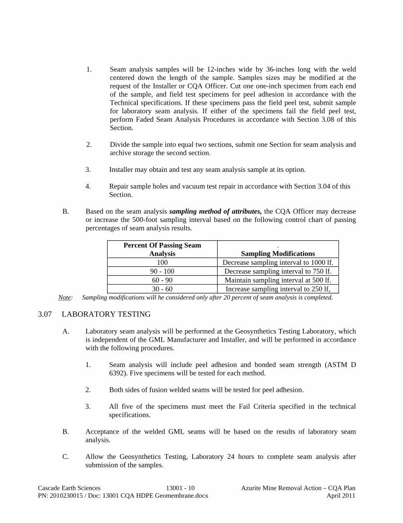
Cascade Earth Sciences 13001 - 10 Azurite Mine Removal Action – CQA Plan PN: 2010230015 / Doc: 13001 CQA HDPE Geomembrane.docx April 2011
1. Seam analysis samples will be 12-inches wide by 36-inches long with the weld
centered down the length of the sample. Samples sizes may be modified at the request of the Installer or CQA Officer. Cut one one-inch specimen from each end of the sample, and field test specimens for peel adhesion in accordance with the Technical specifications. If these specimens pass the field peel test, submit sample for laboratory seam analysis. If either of the specimens fail the field peel test, perform Faded Seam Analysis Procedures in accordance with Section 3.08 of this Section.
2. Divide the sample into equal two sections, submit one Section for seam analysis and
archive storage the second section.
3. Installer may obtain and test any seam analysis sample at its option. 4. Repair sample holes and vacuum test repair in accordance with Section 3.04 of this
Section.
B. Based on the seam analysis sampling method of attributes, the CQA Officer may decrease or increase the 500-foot sampling interval based on the following control chart of passing percentages of seam analysis results.
Percent Of Passing Seam
Analysis .
Sampling Modifications 100 Decrease sampling interval to 1000 lf.
90 - 100 Decrease sampling interval to 750 lf. 60 - 90 Maintain sampling interval at 500 lf. 30 - 60 Increase sampling interval to 250 lf,
Note: Sampling modifications will he considered only after 20 percent of seam analysis is completed. 3.07 LABORATORY TESTING
A. Laboratory seam analysis will be performed at the Geosynthetics Testing Laboratory, which is independent of the GML Manufacturer and Installer, and will be performed in accordance with the following procedures.
1. Seam analysis will include peel adhesion and bonded seam strength (ASTM D
6392). Five specimens will be tested for each method. 2. Both sides of fusion welded seams will be tested for peel adhesion.
3. All five of the specimens must meet the Fail Criteria specified in the technical
specifications.
B. Acceptance of the welded GML seams will be based on the results of laboratory seam analysis.
C. Allow the Geosynthetics Testing, Laboratory 24 hours to complete seam analysis after
submission of the samples.

Cascade Earth Sciences 13001 - 11 Azurite Mine Removal Action – CQA Plan PN: 2010230015 / Doc: 13001 CQA HDPE Geomembrane.docx April 2011
3.08 FAILED SEAM ANALYSIS PROCEDURES
A. In coordination with the Installer, perform the following quality assurance verification procedures in the event of a seam analysis sample failure determined by either field testing or laboratory seam analysis.
1. Track the welded seam 10 feet in both directions away from the failed seam analysis
sample location. Cut a small 12-inch wide by 12-inch long sample from each location. Cut one one-inch specimen from each end of the sample, and field test specimens for peel adhesion in accordance with Part 3.01 of this Section. If these specimens pass the field peel test, submit a 12-inch wide by 18-inch long re-test sample from both locations for laboratory seam analysis. If either of the specimens fail, the field peel test at either location, continue tracking the welded seam at 10-foot intervals until specimens successfully pass the field peel tests and a sample can be submitted for laboratory seam analysis. If specimens continually fail field peel tests at 10-foot intervals, the entire seam or portion of the welded seam will be repaired at the discretion of the CQA Officer.
2. Verify that the failed length of seam is repaired with an 18-inch wide extrusion
welded cap strip. Tack and extrusion welding the leading flap of the fusion welded seam is not permitted. Verify that the extrusion welded cap strip is vacuum tested in accordance with the technical specifications.
3. If the re-test sample fails laboratory seam analysis, repeat the above procedures.
B. Sample extrusion welded cap strips exceeding 100 feet in length for seam analysis.
END OF CQA SECTION 13001 GEOMEMBRANE LINER

Cascade Earth Sciences 13002 - 1 Azurite Mine Removal Action – CQA Plan PN: 2010230015 / Doc:13002 CQA Geotextile.docx April 2011
CQA SECTION 13002 GEOTEXTILE
PART 1 GENERAL 1.01 SUMMARY
A. The CQA Officer shall perform CQA procedures as outlined in this Section and follow guidelines for monitoring and testing to verify and document that geotextile materials and installation are in compliance with the Drawings and Specifications.
1.02 SUBMITTALS
A. Collect three copies of each submittal listed in the Specifications
B. Verify compliance with the submittal schedule and update Submittal Log
C. Perform submittal review and approval procedures in Section 01300-1.03 1.03 TRANSPORT AND STORAGE
A. Upon delivery of the geotextile rolls to the site, verify that the rolls have been transported with opaque protective coverings and within a closed trailer.
B. During unloading of the geotextile rolls at the site, perform the following procedure:
1. Obtain a copy of the packing list
2. Complete the Geotextile Delivery and Control Log for each shipment and attach a copy of the packing list. The Geotextile Delivery and Control Log documents the following:
a. Delivery date b. Roll numbers c. Batch/lot numbers or production dates d. Roll dimensions e. Receipt of MQC test reports f. CQA conformance test sampling g. Receipt of CQA conformance test results h. Manufacturer and Product Name or Designation i. Name of CQA monitor observing delivery and storage j. Total quantity delivered with each shipment and the cumulative total
delivered to date k. Additional notes including rejection of materials, condition of delivered
materials, and other materials included with the shipments
3. Obtain written certification from the Supplier that unloading and storage of the geotextile rolls has been done in accordance with the Manufacturer’s recommended procedures.
4. Verify that geotextile rolls are transported, unloaded, handled, and stored in a manner that does not damage the geotextile rolls or their protective coverings in

Cascade Earth Sciences 13002 - 2 Azurite Mine Removal Action – CQA Plan PN: 2010230015 / Doc:13002 CQA Geotextile.docx April 2011
accordance with the Manufacturer’s recommended procedures and the following requirements:
a. Nylon or other cloth straps shall be used to unload and handle the geotextile rolls to protect the rolls and their protective coverings from damage.
b. The geotextile rolls shall be stacked no more than five rolls high and with a three-foot wide access path between the stacked rows.
5. Verify that damaged protective coverings are repaired or replaced.
6. Identify and separate damaged or rejected geotextile rolls.
7. If CQA conformance test sampling, in accordance with Part 2.03C, is to be performed during delivery to the site, determine which geotextile rolls will be sampled by either individual roll numbers, batch/lot numbers, or production dates and position the rolls for convenient sampling.
PART 2 PRODUCTS 2.01 GEOTEXTILE
A. Verify that geotextiles of each type meets the applicable product requirements of the Specifications.
2.02 SEWING THREAD
A. Verify that sewing thread for geotextiles meets the product requirements of the Specifications.
2.03 CONFORMANCE TESTING
A. Conduct sampling for CQA conformance testing at the site upon delivery or at the manufacturing plant prior to shipment and delivery to the site.
B. For every 100,000 square feet of material delivered to the site, select at least one geotextile
roll of each type to sample for CQA conformance testing.
C. Sample the selected geotextile rolls for CQA conformance testing using the following procedure:
1. Cut and discard the first three feet of geotextile material from across the entire width
of the roll.
2. Cut the next 18 inches of material from across the entire width of the roll; this section of material is the CQA conformance testing sample.
3. Assign a CQA test number to the sample and mark the following information directly on the sample with a paint marker:
a. Machine direction of the sample
b. Manufacturer’s roll number
c. CQA test number

Cascade Earth Sciences 13002 - 3 Azurite Mine Removal Action – CQA Plan PN: 2010230015 / Doc:13002 CQA Geotextile.docx April 2011
4. Immediately re-wrap the sampled geotextile roll with its protective covering; use additional opaque plastic sheeting, if needed, to completely cover the roll.
5. Complete the Geotextile Test Request and Sample Custody Log and ship samples to the Geosynthetics Testing Laboratory via overnight delivery.
D. The following CQA conformance tests will be performed by the Geosynthetics Testing
Laboratory to verify compliance with the product requirements of the Specifications:
1. Mass Per Unit Area (ASTM D 5261) 2. Grab Strength (ASTM D 4632) 3. Trapezoidal Tear Strength (ASTM D 4533) for filter only 4. Puncture (ASTM D 4833) for filter only 5. Permittivity (ASTM D 4491) for filter only 6. Apparent Opening Size (ASTM D 4751) for filter only
E. Upon completion of CQA conformance testing and receipt of the results, review all results
for compliance with the Specifications and report any test results which are not in compliance with the Specifications to the Engineer.
F. Additional CQA conformance testing or corrective action to be performed in the event of test
results which are not in compliance with the Specifications will be determined by the Engineer.
PART 3 EXECUTION 3.01 PREPARATION AND EXAMINATION
A. Prior to geotextile installation, hold a preparatory meeting in accordance with Section 01039-1.04 of this CQA Plan.
B. Prior to geotextile installation, verify that all underlying material installation and construction
has been completed in accordance with the Specifications. 3.02 INSTALLATION
A. Verify that the geotextile is installed in accordance with Manufacturer’s instructions for deployment, seaming, and exposure.
B. Verify that the geotextile is installed with the machine direction (lengthwise) of the roll
oriented down the slope. C. Verify that the geotextile is installed with sufficient tension to prevent excessive
overlapping, insufficient overlapping, wrinkles, and folds. D. Verify that geotextile panels are overlapped with sufficient material to create a prayer fold
for sewing. E. Verify that the geotextile is adequately ballasted during installation and until geotextile is
covered with the overlying material.

Cascade Earth Sciences 13002 - 4 Azurite Mine Removal Action – CQA Plan PN: 2010230015 / Doc:13002 CQA Geotextile.docx April 2011
F. Verify that the geotextile is permanently anchored as shown on the Drawings when
installation is complete.
G. Verify that geotextile damaged during installation is removed and/or repaired with a sewn patch.
H. Verify that terminal ends of geotextile, where the type and purpose of the geotextile changes
as shown on the Drawings, are overlapped a minimum of four feet.
I. Verify that when cutting any geotextile above the GML, the Installer uses a knife with a hooked blade.
J. Verify that the underlying soil subgrade or installed geosynthetics are not damaged by
geotextile installation equipment or methods and that any damaged soil subgrade or installed geosynthetics are completely repaired in accordance with the requirements of the applicable section of the Specifications.
K. Verify that rocks, excessive dust, excessive moisture or other matter that could cause
damage, hamper sewing operations, or clog the geotextile are not trapped under the geotextile or within the overlap.
3.03 SEAMING AND REPAIR
A. Verify that all seams are sewn unless an alternate seaming method is allowed by the Engineer
based on the Installer’s demonstration of the alternative acceptability.
B. Verify that overlaps are clean and free of soil materials which could adversely affect sewing operations.
C. Verify that a prayer fold is made within the overlap prior to sewing.
D. Verify that a continuous 401 two-thread chain stitch is used to sew the prayer fold.
E. Verify that damaged geotextile is removed entirely and replaced or repaired in accordance
with the following guidelines:
1. Repair (patching) material shall be of the same type as the damaged geotextile.
2. Patches shall extend a minimum of 12 inches in all directions beyond the damaged area with the machine direction of the patch aligned with the machine direction of the damaged geotextile.
3. Patches shall be seamed using the same method used for seaming the damaged geotextile.
END OF CQA SECTION 13002 GEOTEXTILE

Cascade Earth Sciences 13003 - 1 Azurite Mine Removal Action –CQA Plan PN: 2010230015 / Doc: 13003 CQA Geogrid.docx April 2011
CQA SECTION 13003 GEOGRID
PART 1 GENERAL 1.01 SUMMARY
A. The CQA Officer shall perform CQA procedures as outlined in this Section and follow guidelines for monitoring and testing to verify and document that geogrid materials and installation are in compliance with the Drawings and Specifications.
1.02 SUBMITTALS
A. Collect three copies of each submittal listed in the Specifications
B. Verify compliance with the submittal schedule and update Submittal Log
C. Perform submittal review and approval procedures in Section 01300-1.03 1.03 TRANSPORT AND STORAGE
A. Upon delivery of the geotextile rolls to the site, verify that the rolls have been transported with opaque protective coverings.
B. During unloading of the geogrid rolls at the site, perform the following procedure:
1. Obtain a copy of the packing list
2. Complete the Geogrid Delivery and Control Log for each shipment and attach a copy of the packing list. The Geogrid Delivery and Control Log documents the following:
a. Delivery date b. Roll numbers c. Batch/lot numbers or production dates d. Roll dimensions e. Receipt of MQC test reports f. CQA conformance test sampling g. Receipt of CQA conformance test results h. Manufacturer and Product Name or Designation i. Name of CQA monitor observing delivery and storage j. Total quantity delivered with each shipment and the cumulative total
delivered to date k. Additional notes including rejection of materials, condition of delivered
materials, and other materials included with the shipments
3. Obtain written certification from the Supplier that unloading and storage of the geotextile rolls has been done in accordance with the Manufacturer’s recommended procedures.

Cascade Earth Sciences 13003 - 2 Azurite Mine Removal Action –CQA Plan PN: 2010230015 / Doc: 13003 CQA Geogrid.docx April 2011
4. Verify that geogrid rolls are transported, unloaded, handled, and stored in a manner that does not damage the geogrid rolls or their protective coverings in accordance with the Manufacturer’s recommended procedures and the following requirements:
a. Nylon or other cloth straps shall be used to unload and handle the geogrid rolls to protect the rolls and their protective coverings from damage.
b. The geogrid rolls shall be stacked no more than five rolls high and with a three-foot wide access path between the stacked rows.
5. Verify that damaged protective coverings are repaired or replaced.
6. Identify and separate damaged or rejected geogrid rolls.
7. If CQA conformance test sampling, in accordance with Part 2.03C, is to be performed during delivery to the site, determine which geogrid rolls will be sampled by either individual roll numbers, batch/lot numbers, or production dates and position the rolls for convenient sampling.
PART 2 PRODUCTS 2.01 GEOGRID
A. Verify that geogrids of each type meets the applicable product requirements of the Specifications.
2.02 NOT USED 2.03 CONFORMANCE TESTING
A. Conduct sampling for CQA conformance testing at the site upon delivery or at the manufacturing plant prior to shipment and delivery to the site.
B. For every 100,000 square feet of material delivered to the site, select at least one geogrid roll
of each type to sample for CQA conformance testing.
C. Sample the selected geogrid rolls for CQA conformance testing using the following procedure:
1. Cut and discard the first three feet of geogrid material from across the entire width
of the roll.
2. Cut the next 18 inches of material from across the entire width of the roll; this section of material is the CQA conformance testing sample.
3. Assign a CQA test number to the sample and mark the following information directly on the sample with a paint marker:
a. Machine direction of the sample
b. Manufacturer’s roll number
c. CQA test number

Cascade Earth Sciences 13003 - 3 Azurite Mine Removal Action –CQA Plan PN: 2010230015 / Doc: 13003 CQA Geogrid.docx April 2011
4. Immediately re-wrap the sampled geogrid roll with its protective covering; use additional opaque plastic sheeting, if needed, to completely cover the roll.
5. Complete the Geogrid Test Request and Sample Custody Log and ship samples to the Geosynthetics Testing Laboratory via overnight delivery.
D. The following CQA conformance tests will be performed by the Geosynthetics Testing
Laboratory to verify compliance with the product requirements of the Specifications:
1. Long-Term Strength (LTDS) (GRI GG4-MD)
E. Upon completion of CQA conformance testing and receipt of the results, review all results for compliance with the Specifications and report any test results which are not in compliance with the Specifications to the Engineer.
F. Additional CQA conformance testing or corrective action to be performed in the event of test
results which are not in compliance with the Specifications will be determined by the Engineer.
PART 3 EXECUTION 3.01 PREPARATION AND EXAMINATION
A. Prior to geogrid installation, hold a preparatory meeting in accordance with Section 01039-1.04 of this CQA Plan.
B. Prior to geogrid installation, verify that all underlying material installation and construction
has been completed in accordance with the Specifications. 3.02 INSTALLATION
A. Verify that the geogrid is installed in accordance with Manufacturer’s instructions for deployment, seaming, and exposure.
B. Verify that the geogrid is installed with the machine direction (lengthwise) of the roll
oriented down the slope. C. Verify that the geogrid is installed with sufficient tension to prevent excessive overlapping,
insufficient overlapping, wrinkles, and folds. D. Verify that the geogrid is adequately ballasted during installation and until geotextile is
covered with the overlying material.
E. Verify that the geogrid is permanently anchored as shown on the Drawings when installation is complete.
F. Verify that geogrid damaged during installation is removed and/or repaired with a sewn
patch.

Cascade Earth Sciences 13003 - 4 Azurite Mine Removal Action –CQA Plan PN: 2010230015 / Doc: 13003 CQA Geogrid.docx April 2011
G. Verify that when cutting any geogrid above the GML, the Installer uses a knife with a hooked
blade.
H. Verify that the underlying soil subgrade or installed geosynthetics are not damaged by geogrid installation equipment or methods and that any damaged soil subgrade or installed geosynthetics are completely repaired in accordance with the requirements of the applicable section of the Specifications.
END OF CQA SECTION 13003 GEOGRID

Appendix F.
HELP Model Results

TECHNICAL MEMORANDUM DATE: December 28, 2007 TO: Rod Lentz – U.S. Forest Service FROM: Jay Williams – Cascade Earth Sciences
SUBJECT: HELP Model Summary of Results Azurite Mine Removal Action, Mazama, Washington
The attached seepage analysis was performed to estimate the relative amount of seepage that would flow through the repository designed for the Azurite Mine Removal Action either with or without an impervious (Bentomat) liner as part of the repository cover. It can also be used to estimate the amount of treatment that may be necessary to remove leached contaminants from the leachate stream. The modeling was performed using HELP Model Version 3.07, developed for U.S. EPA. The runs named AZURAVE1 and AZURAVE2 were constructed using daily average temperatures, precipitation, solar radiation, and evapotranspiration data for Mazama Washington. The daily averages for a year were used repeatedly through the multiyear model. Other parameters are given in Table 1. AZURAVE1 is modeled with a relatively impervious bentomat liner between the cover and the wasterock, whereas AZURAVE2 is modeled with the same climatic, cover, wasterock and native soil parameters but without the impervious liner. Seepage out of the repository averages 0.3 inches per year when modeled with the impervious liner. Seepage out of the repository averages 2.4 inches per year when modeled without the impervious liner. The runs named AZURSYN1 and AZURSYN2 were constructed using a synthesized data set from the model for temperatures, precipitation, solar radiation, and evaportranspiration for Yakima Washington. Soil parameters are given in Table 1. AZURSYN1 is modeled with a relatively impervious bentomat liner between the cover and the wasterock, whereas AZURSYN2 is modeled with the same climatic, cover, wasterock and native soil parameters but without the impervious liner. Seepage out of the repository averages 0.01 inches per year when modeled with the impervious liner. Seepage out of the repository averages 0.1 inches per year when modeled without the impervious liner. Using the synthesized data allowed us to see how much variability occurred from year to year in a relatively short time. AZURSYN 1 seepage averaged 42 cubic feet per year (CF/Y) but varied from 0 CF/Y to 606 CF/Y with 84% of years showing zero seepage. AZURSYN 2 seepage averaged 294 CF/Y and varied from 0 CF/Y to 4,114 CF/Y with 60% of years showing zero seepage. The climatic data from Mazama may be more representative of conditions at the mine site. It would appear reasonable to assume that seepage rates with an impervious cover would average about 900 CF/Y and vary from 0 to 12,000 CF/Y. Without the impervious cover seepage rates would average about 7000 CF/Y and vary from 0 to 98,000 CF/Y. jw PN: 2723031 Doc: HELP Tech Memo.doc

Table 1. HELP Model Paramaters
AZURAVE1 AZURAVE2 AZURSYN1 AZURSYN2Precipitation Mazama Avg Mazama Avg Yakima Syn Yakima SynTemperature Mazama Avg Mazama Avg Yakima Syn Yakima SynSolar Radiation Mazama Avg Mazama Avg Yakima Syn Yakima SynEvapotranspiration Mazama Avg Mazama Avg Yakima Syn Yakima Syn
Thickness, inches 24 24 24 24Porosity 0.463 0.463 0.463 0.463Field Capacity 0.232 0.232 0.232 0.232Wilting Point 0.116 0.116 0.116 0.116Initial Soil Water Content 0.1639 0.1652 0.1829 0.1829Hydraulic Conductivity 3.70E-04 3.70E-04 3.70E-04 3.70E-04
Thickness, inches 0.24 N/A 0.24 N/APorosity 0.75 N/A 0.75 N/AField Capacity 0.747 N/A 0.747 N/AWilting Point 0.4 N/A 0.4 N/AInitial Soil Water Content 0.75 N/A 0.75 N/AHydraulic Conductivity 3.00E-09 N/A 3.00E-09 N/A
Thickness, inches 264 264 264 264Porosity 0.419 0.419 0.419 0.419Field Capacity 0.307 0.307 0.307 0.307Wilting Point 0.18 0.18 0.18 0.18Initial Soil Water Content 0.307 0.3086 0.307 0.307Hydraulic Conductivity 1.90E-05 1.90E-05 1.90E-05 1.90E-05
Thickness, inches 120 120 120 120Porosity 0.46 0.46 0.46 0.46Field Capacity 0.36 0.36 0.36 0.36Wilting Point 0.203 0.203 0.203 0.203Initial Soil Water Content 0.36 0.36 0.36 0.36Hydraulic Conductivity 9.00E-06 9.00E-06 9.00E-06 9.00E-06
Native Soil
HELP Runs
Cover Soil
Barrier Layer
Wasterock Layer
Cascade Earth Sciences - Spokane, WAPN: 2723031
Azurite MineDecember 2007

Appendix G.
Project Construction Schedule

ID Task Name Duration Start Finish
1 Year 1 - Removal Action Construction 79 days Mon 6/20/11 Fri 10/7/11
2 Spring 2011 Aquatic Monitoring 4 edays Mon 6/20/11 Fri 6/24/11
3 Pre Construction Survey 5 edays Fri 6/24/11 Wed 6/29/11
4 Mobilize equipment, Install Stormwater Controls, Setup Camp 5 edays Mon 6/27/11 Sat 7/2/11
5 Clearing and Grubbing 3 edays Sat 7/2/11 Tue 7/5/11
6 Construct Road from Repository to Wasterock 5 edays Sat 7/2/11 Thu 7/7/11
7 Setup Talus Screen 5 edays Sat 7/2/11 Thu 7/7/11
8 Construct Re-Enforced Berm and Toe 10 edays Thu 7/7/11 Sun 7/17/11
9 Wasterock Excavation, Placement, and Repository Construction 60 edays Thu 7/7/11 Mon 9/5/11
10 Construct Final Runon/Runoff Ditches 5 edays Mon 9/5/11 Sat 9/10/11
11 Install Bat Gates 15 edays Mon 9/5/11 Tue 9/20/11
12 Building Material Disposal 3 edays Tue 9/20/11 Fri 9/23/11
13 Post Construction Survey 5 edays Fri 9/23/11 Wed 9/28/11
14 Road Obliteration and Revegetation 5 edays Fri 9/23/11 Wed 9/28/11
15 Demobilize 5 edays Wed 9/28/11 Mon 10/3/11
16 Fall 2011 Aquatic Monitoring 4 edays Mon 10/3/11 Fri 10/7/11
17 Year 2 - 2012 Post RA Monitoring 70 days Mon 6/25/12 Mon 10/1/12
20 Year 3 - 2013 Post RA Monitoring 70 days Mon 6/24/13 Mon 9/30/13
23 Year 4 - 2014 Post RA Monitoring 70 days Mon 6/23/14 Mon 9/29/14
Year 1 - Removal Action Construction5/29 6/5 6/12 6/19 6/26 7/3 7/10 7/17 7/24 7/31 8/7 8/14 8/21 8/28 9/4 9/11 9/18 9/25 10/2 10/9 10/16 10/23 10/30 11/6
3rd Quarter 4th Quarter
Task
Split
Progress
Milestone
Summary
Project Summary
External Tasks
External Milestone
Deadline
Azurite Mine Removal Action Preliminary Schedule
Page 1
Project: Azurite Removal Action ConstDate: Fri 1/28/11

Appendix H.
Construction Cost Estimate

Appendix H. Construction Cost EstimateAzurite Mine Removal Action Work Plan, Okanogan National Forest, Washington
Description Total CostDirect Capital
Contractor Mobilization 72,000$ Erosion / Sediment Control - 2 events 31,000$ Site Seeding (USFS Provided seed) 2,400$ Access Road Maintenance 24,000$ Misc. Onsite Road Construction/Obliteration 12,000$ Remote Camp/Logistics 120,000$ Demolition / Haul Away Debris 5,000$ Wasterock Excavation and Repository Construction 349,000$ Stabilized Slope/Berm - Repository Face 171,000$ Tailings Regrade and Cover Construction 862,000$ Mill Area Grading and Cover Construction 121,000$ Runon / Runoff Control 66,000$ Mill Creek Crossing and Maintenance 8,000$ Bat Gates (5 closures, including helicopter use and fabrication) 50,000$
Direct Capital Subtotal 1,893,400$ Project Management/Oversight @ 20% Direct Capital Cost 378,680$
- includes remote logistics, supplies, oversight, reporting, etc.Indirect Capital Subtotal 378,680$
Total Direct and Indirect Costs 2,272,080$
Cascade Earth Sciences - Spokane, WAPN: 2010230015 / Doc: 2011 Azurite Mine RA Cost Estimate.xls (App H. Summary Cost)
Azurite Mine - Removal Action Work PlanApril 2011

Appendix I.
Draft Operation and Maintenance Plan

November 2005
Draft Operations and Maintenance Plan Azurite Mine Removal Action Okanogan National Forest Whatcom County, Washington
March 2010
Cascade Earth Sciences12720 E. Nora Ave., Ste A
Spokane, WA 99216 (509) 921-0290
www.cascade-earth.com
Disclaimer: The contents of this document are confidential to the intended recipient at the location to which it has been addressed. The contents may not be changed, edited, and/or deleted. The information contained in this document is only valid on the date indicated on the original project file report retained by CES. By accepting this document, you understand that neither CES nor its parent company, Valmont Industries, Inc. (Valmont) accepts any responsibility for liability resulting from unauthorized changes, edits, and/or deletions to the information in this document.
Draft Operations and Maintenance Plan Azurite Mine Removal Action Okanogan National Forest Whatcom County, Washington Prepared For: Mr. Rod Lentz U.S. Forest Service Okanogan and Wenatchee National Forests 1240 2nd Avenue South Okanogan, Washington 98840 Prepared By: Cascade Earth Sciences
12720 E. Nora Avenue, Suite A Spokane, Washington 99216 (509) 921-0290
Author: Jay E. Williams, PE, Managing Engineer II Reviewed By: Dustin G. Wasley, PE, Principal Engineer Report Date: March 2010 Project Number: 2721031 Submitted By: Dustin G. Wasley, PE, Principal Engineer

Cascade Earth Sciences – Spokane, WA Azurite Mine Removal Action PN: 2723031 Draft Operations and Maintenance Plan Doc: Draft Azurite Operations and Maintenance Plan.docx March 2010 / Page v
CONTENTS 1.0 SUMMARY OF EXISTING FACILITIES ........................................................................................ 1
2.0 EMERGENCY CONTACT NAMES AND NUMBERS ................................................................... 1
3.0 DESCRIPTION OF NORMAL OPERATIONS AND MAINTENANCE ......................................... 2 3.1 Logistics ............................................................................................................................................... 2 3.2 Operations ............................................................................................................................................ 3
3.2.1 Above Ground Visual Inspection (Annually) ......................................................... 3 3.2.2 Water Treatment Systems ........................................................................................ 4
4.0 CONTINGENCY OPERATIONS AND MAINTENANCE .............................................................. 4 4.1 Safety Plan ........................................................................................................................................... 4
5.0 EMERGENCY PROCEDURES – IMMEDIATE .............................................................................. 5
6.0 EMERGENCY PROCEDURES - SECONDARY ............................................................................. 6
7.0 HOSPITAL ROUTE TO THE COUNTY CLINIC IN WINTHROP, WASHINGTON .................... 6 7.1 County Clinic (1116 Highway 20, Winthrop, Washington 98862) ................................................. 6 7.2 Potential Physical Hazards ................................................................................................................. 8
DRAWING Sheet G-1. Site Location Map
ATTACHMENTS Attachment A. Inspection Checklists (to be developed following Removal Action) Attachment B. Job Hazard Analysis (to be developed following Removal Action)

Cascade Earth Sciences – Spokane, WA Azurite Mine Removal Action PN: 2723031 Draft Operations and Maintenance Plan Doc: Draft Azurite Operations and Maintenance Plan.docx March 2010 / Page 1
1.0 SUMMARY OF EXISTING FACILITIES The Azurite Mine (Site), as delineated on Drawing G-1 is located in Whatcom County, Washington, in Section 18, Township 37 north, and Range 17 east of the Willamette Meridian. This location is in the Mt. Baker-Snoqualmie National Forest (administered by the Okanogan and Wenatchee National Forests), near the southern edge of the Pasayten Wilderness Area, and approximately 19 air miles northwest of Mazama, Washington. The driving time, one-way, from Mazama to the Site is approximately 2.5 hours, depending on road and trail conditions. The Site is accessed from Mazama, Washington by taking County Road (CR) 9140 northwesterly. It will turn into Forest road (FR) 5400. Continue on FR 5400 to Harts Pass (approximately ten miles from Mazama to the pass). At Harts Pass, turn left onto FR 700. Follow FR 700 to Forest Trail (FT) 475 and go left. Take FT 475 past the Whistler Mine, over Cady Pass, and down to Mill Creek. At FT 755, go left and along Mill Creek to the Azurite Mine and Tailing area (total distance traveled from Mazama is about 24 miles). The Removal Action at the Site includes the excavation and transport of wasterock piles from the west side of Mill Creek to the repository on the south side of the tailings pile, stabilize the tailings pile in place by providing positive drainage and covering with an impermeable liner, and installing bat gates at the Wenatchee and Tinson Adits. The upper wasterock pile will be placed as the bottom lift in the repository, while the lower wasterock pile will be placed on top of the upper wasterock pile. The face of the repository will be wrapped with a Uniaxial Geogrid to maintain long-term structural stability. The repository cover will consist of an impermeable liner, an eight-ounce non-woven geotextile, cover soil, and vegetation. The tailing pile will be minimally disturbed to promote positive, non-erosional drainage along the various benches. The tailings pile cover will consist of an impermeable liner, an eight-ounce non-woven geotextile, and talus material. Cover soil will also be placed along the benches of the tailings pile to help promote and establish the native vegetation. Other work will consist of improving the access road by installing multiple culverts, repairing several bridges, and widening the road to allow equipment access to the Site. In addition, water discharging from the tailings seep, the wasterock seep, and the Tinson Adit may be treated/managed using a method to be determined in the future. Signs will also be posted to warn the public of the general hazards (both chemical and physical) associated with the tailings, wasterock, and metal-impacted seeps/drainages. 2.0 EMERGENCY CONTACT NAMES AND NUMBERS The following calling list must be updated annually with the appropriate contact information. The numbers are listed according to priority. In the event of an immediate emergency, contact the appropriate Emergency Responder. Second, call the Forest Service. If the event being reported presents a potential endangerment to the public or Forest Service personnel, call and report the event to the Forest Service Safety and Occupational Health Manager then notify the remaining Forest Service personnel in priority of the list.

Cascade Earth Sciences – Spokane, WA Azurite Mine Removal Action PN: 2723031 Draft Operations and Maintenance Plan Doc: Draft Azurite Operations and Maintenance Plan.docx March 2010 / Page 2
Emergency Phone Numbers
Medical Emergency/Ambulance .................................................................... 911 Police ................................................................................................................ 911 Fire .................................................................................................................... 911 CES Spokane Office .................................................................... (509) 921-0290 Forest Service Methow Valley Ranger District-Winthrop ....... (509) 996-4000 Okanogan County Sheriff’s Office. ............................................ (509) 422-7232 Winthrop Fire Dept ...................................................................... (509) 997-4040 Washington Department of Natural Resources (fires) ............... (800) 562-6010 County Clinic ............................................................................... (509) 996-8180 1116 Highway 20 Winthrop, Washington 98862
3.0 DESCRIPTION OF NORMAL OPERATIONS AND MAINTENANCE Operation and maintenance is composed of two separate tasks:
• Operational tasks which are undertaken to allow for the continued effective operation of the system in accordance with the design. Given the nature of the Azurite Mine Removal Action, operational tasks are limited.
• Maintenance tasks, which are undertaken to inspect and correct problems with the system and to control disruptions in service. Maintenance tasks typically consist of routine inspection and repair activities, as well as, regular ongoing tasks to maintain the system.
The following table summarized the tasks and involved.
Operation Task 1 (Inspection)
Maintenance Task Frequency
Min. No. of People
Required 2
Conducted By
Health and Safety Training and Guidelines
Responsibility Above Ground
Visual Inspection Annually 1 TBD TBD
Underground Visual Inspection As Needed 3 TBD TBD
Water Treatment Systems 3 TBD TBD TBD TBD
NOTES: 1 See Attachment A for checklists that may be used as a tool to facilitate inspections both above and underground. 2 Underground entry shall be by Health and Safety Code Handbook 6709.2007-1, which requires three people. 3 To Be Determined (TBD) 3.1 Logistics
Should bat gate keys be needed for underground entry, they can be obtained from the local Forest Service office. Bring appropriate safety equipment and the site-specific health and safety plan (HASP) to the Site. Review the Job Hazard Analysis (JHA; Attachment B) with all employees onsite and have them sign that they understand the hazards and mitigation recommendations.

Cascade Earth Sciences – Spokane, WA Azurite Mine Removal Action PN: 2723031 Draft Operations and Maintenance Plan Doc: Draft Azurite Operations and Maintenance Plan.docx March 2010 / Page 3
• Appropriate equipment list for above ground work: o gloves o hardhat o weather appropriate clothing o eye protection o nonskid steel-toed safety boots
• Appropriate equipment list for underground work: o gloves o Forest Service approved hardhat with mine light o long pants, long sleeve shirts o eye protection o nonskid steel-toed safety boots o multi-gas meter that is
capable of detecting at least oxygen, and has an audible and visual display alarm indicator.
o first aid kit o two-way radio for check-in o specific items for condition requiring additional protective measures as identified in the JHA o optional personal protective equipment (includes a self-rescuer)
• Before leaving the Site: o confirm that the Site is free of trash and all gear has been removed; o verify that all bat gates are locked; and o replace and bolt all service gates.
3.2 Operations
The Forest Service is not responsible for contractor safety and has rules and requirement regarding health and safety. Forest Service personnel should comply with required safety documentation prior to working on the Site. The Forest Service is not responsible for the contractors’ safety documentation. A HASP for the Site will be provided by the contractor prior to working onsite. Underground and above ground inspection checklists are available in Attachment A. 3.2.1 Above Ground Visual Inspection (Annually)
Work will be performed annually by the Forest Service. Visually inspect the Site for damage, erosion, and proper operations of the access road and gate, bridges, drainage ditches/culverts, repositories, and other features. If issues arise during visual inspection, proceed to the contingency operations and maintenance portion of this document (Section 4.0).
1. Is there flow from the pipeline discharging into the drainage ditch on the west side of the repository?
2. Is there any visual evidence of system failure?
• Iron stains on hillside?
• Iron stains or iron precipitate in Mill Creek?

Cascade Earth Sciences – Spokane, WA Azurite Mine Removal Action PN: 2723031 Draft Operations and Maintenance Plan Doc: Draft Azurite Operations and Maintenance Plan.docx March 2010 / Page 4
3. Has the backfill over the tailing pile or wasterock repository been eroded or suffered other damage?
4. Are the adits clear of debris?
5. Are the bat gates locked and intact? 3.2.2 Water Treatment Systems
To be determined at a later date. 4.0 CONTINGENCY OPERATIONS AND MAINTENANCE If a situation is encountered that will potentially impact the health and safety of the public immediately notify the Contracting Officer Representative (COR), Rod Lentz at (509) 826-3274.
• If embankment failure, increased seepage, or other damage are encountered during inspection, take the following steps:
1. Notify the following personnel immediately and request instruction on how to proceed:
o Local Forest Service main office: (509) 996-4000
o Forest Service Minerals and Special Use Administrator: Laurie Dowie (509) 996-4071
o Forest Service Regional Environmental Engineer: Julie Creed (503) 808-2526
o Forest Service COR: Rod Lentz (509) 826-3274
2. Document the event and send a copy to the Safety and Occupational Health Manager and the District Minerals and Special Use Administrator.
4.1 Safety Plan
For Forest Service employees to go underground (enter at portal): All Forest Service employees must comply with FSH 6709-11 (Forest Service Health and Safety Code Handbook), Chapter 20, Interim Directive 6709-11-2007-1, which requires at least one Qualified Certified Mineral Examiner or Qualified Mineral Safety Lead to lead any underground mine assessment. The Interim Directive also specifies the personal protective equipment required for underground entry, including hardhat, safety-toed boots, eye protection, headlamp, safety belt, multi-gas meter, first aid kit, two-way radio, other items identified in the JHA, communication, and optionally a self-rescuer. Follow Interim Directive 6709-11-2007-1 for any underground entry. For Contractors: All contractors and non-Forest Service personnel onsite to perform work must provide their own HASP according to Occupational Safety and Health Administration regulations for hazardous waste sites (see CPL 02-02-071 – Technical Enforcement and Assistance Guidelines for Hazardous Waste Site and RCRA Corrective Action Clean-up Operations HAZWOPER 1910-120 (b) – (o) Directive and others). Potentially hazardous or unsafe underground environments include: Confined space hazard, rock falls, slip/trip/fall hazards, low oxygen, elevated carbon monoxide or other hazardous atmospheres, adit or portal collapse, and wildlife (snakes, bats, etc.). The site entry JHA or HASP must address these and any other onsite hazards. Specifically, inspection of any underground bulkhead must be addressed in the JHA or HASP.

Cascade Earth Sciences – Spokane, WA Azurite Mine Removal Action PN: 2723031 Draft Operations and Maintenance Plan Doc: Draft Azurite Operations and Maintenance Plan.docx March 2010 / Page 5
Emergency Contacts: Contacting emergency assistance is difficult from the Site. Cell phone and two-way radio (other than tactical frequency) will not work at the Site. Satellite radios do work at the Site and should be used for communications. Forest Service employees should attempt to contact Dispatch as well as initiating medical assistance response. Forest Service employees should fill out a Serious Incident Information Report (“pink sheet”) when time allows. The following table gives emergency contact information in case of an accident or incident at the Site. After summoning any needed emergency medical assistance and stabilizing people involved, contact the District Ranger or Acting District Ranger for the Site. If after hours, call the after-hours number for Dispatch, which in turn will contact the Safety Manager / Hazardous Waste Lead, and the appropriate level of management.
Azurite Mine Site
Medical emergency/Ambulance ................................................................................ 911 Aero Methow Rescue Service (Twisp) ................................................. (509) 997-4013 County Clinic ......................................................................................... (509) 996-8180 1116 Highway 20 Winthrop, WA 98862 Fire .............................................................................................................................. 911 Washington Department of Natural Resources (fires) ......................... (800) 562-6010 Winthrop Fire Dept ................................................................................ (509) 997-4040 Police .......................................................................................................................... 911 CES Spokane Office .............................................................................. (509) 921-0290 Methow Valley Ranger District-Winthrop ........................................... (509) 996-4000 Okanogan County Sheriff’s Office. ...................................................... (509) 422-7232 Washington Department of Natural Resources -Sedro Woolley ......... (360) 856-3500
5.0 EMERGENCY PROCEDURES – IMMEDIATE
1. ASSESS SITUATION o What is the Hazard? o Can the Site be entered? o Does the hazard still exist? Because the Site requires mine entry atmospheric and rock fall
hazards must be assessed.
2. MAKE THE SITE SAFE o Is Site entry safe for others?
3. ASSESS THE VICTIM o breathing o heartbeat o other life threatening conditions

Cascade Earth Sciences – Spokane, WA Azurite Mine Removal Action PN: 2723031 Draft Operations and Maintenance Plan Doc: Draft Azurite Operations and Maintenance Plan.docx March 2010 / Page 6
4. CALL 911: Follow oral reporting procedures below. If injuries are life threatening, request instructions from dispatch. If injuries are not life threatening, remove the victim from the contamination zone or injury area. Consider the need for decontamination prior to transport. Provide the following to dispatch: o Name, location, and phone number of person reporting; o Location of accident/incident; o How many victims need help; o Description of injuries; o Details of any chemicals or other contamination involved; o Summary of the accident including its suspected cause and the time it occurred; o Summary of what is being done for the victim(s); o Depending on the severity of the accident you may want to suggest helicopter transport, or
meeting the ambulance somewhere along the transport route; and o Do not hang up until the other party has done so.
5. APPLY EMERGENCY FIRST AID IF TRAINED: Remove the injured party from contaminated or other unsafe zones, per Occupational Safety and Health Administration HAZWOPER guidelines. Ensure victim is breathing and reduce any immediate threat to life.
6.0 EMERGENCY PROCEDURES - SECONDARY
1. Transport to hospital, if possible, otherwise call ambulance (911). 2. Notify Forest Service and other key personnel.
7.0 HOSPITAL ROUTE TO THE COUNTY CLINIC IN WINTHROP, WASHINGTON 7.1 County Clinic (1116 Highway 20, Winthrop, Washington 98862)
For severe injuries (i.e., loss of appendage or heart attack), a helicopter could be used to airlift the injured to the hospital. The first responder will coordinate with the Forest Service to establish a suitable landing site.

Cascade Earth Sciences – Spokane, WA Azurite Mine Removal Action PN: 2723031 Draft Operations and Maintenance Plan Doc: Draft Azurite Operations and Maintenance Plan.docx March 2010 / Page 7
MAP: Azurite Mine to the County Clinic in Winthrop, Washington
Directions (Distance and time approximate due to remote location) Distance
Total Est. Time: 2 hours Total Est. Distance: 52.5 miles
1: From the Site, travel generally EAST approximately 10 miles over primitive road to the parking area at Slate Creek.
11 miles
2: Travel East approximately 5 miles on NF-374 and NF-700 to Junction with NF-5400 (Hart Pass).
5 miles
3: Then SOUTHEAST on NF-5400 to Junction with NF-060 9.7 miles
4: Turn Left onto NF-060. 2.4 miles
5: Continue on Lost Creek Road 0.1 mile, stay left and continue on Lost Creek Road. 6.5 miles
6: Turn RIGHT on Mazama Road 0.4 miles
6: Turn LEFT at WA-20. 17.5 miles
7: End at Country Clinic: 1116 Highway 20, Winthrop, WA 98862, US
Total Est. Time: 2 hours. Total Est. Distance: 52.5 miles

Cascade Earth Sciences – Spokane, WA Azurite Mine Removal Action PN: 2723031 Draft Operations and Maintenance Plan Doc: Draft Azurite Operations and Maintenance Plan.docx March 2010 / Page 8
7.2 Potential Physical Hazards
A checklist of physical hazards is provided as follows. Details on several items are presented in the sections following the table.
Description Hazard
Comments Yes No
Overhead Power Lines X None present at Site.
Tree Snags X Likely present at the Site. Will work with the On-Scene Coordinator to determine methods for removal.
Buried Conduit X There are likely buried water lines at the Site; however, no power lines will be present.
Fatigue X Sleeping in tents. Personnel will monitor each other for alertness and the Site Safety Officer will require fatigued personnel to leave the work area and rest.
Gastro-intestinal illness X Diarrhea and other GI tract illnesses can be a hazard due to poor hygiene. Personnel will wash their hands with soap after visiting the toilet and before eating.
Uneven Ground X Appropriate precautions will be taken while traversing the area.
Fall Hazards X Appropriate precautions will be taken while traversing the area.
Steep Slopes X Appropriate precautions will be taken while traversing the area.
Ice X Ice may be present depending on season and weather conditions.
Extreme Temperatures X Field activities are scheduled for mid-July through September and temperatures could be a factor.
Slippery Conditions X Slippery conditions may be present depending on weather conditions. Appropriate precautions will be taken while traversing the area.
Rain X Rain may exacerbate hazardous conditions.
Open adits X No personnel will enter adits open to the surface.
Rodent Droppings X Possible in buildings at the Site. Potential Collapsed Workings X There is the potential for adits to collapse. Appropriate precautions will be taken
while traversing the Site. No personnel will knowingly enter an adit.
Abandoned Structures X There is one abandoned structure at the Site. It should be inspected by a competent person prior to entry or use.
As shown in the checklist, physical hazards at the Site are primarily due to steep slopes in the mountainous terrain, weather conditions, heavy equipment, and mine openings. These include hazards such as operating a field vehicle in steep terrain with poor roads, twisting an ankle while traversing the slopes, slipping or tripping on obstructions, falls into collapsed underground mine workings, and exposure to the heat or cold. Activities will follow standard operating procedures to minimize the chance of human error and will be conducted in a safe and prudent manner.

Cascade Earth Sciences – Spokane, WA Azurite Mine Removal Action PN: 2723031 Draft Operations and Maintenance Plan Doc: Draft Azurite Operations and Maintenance Plan.docx March 2010 / Page 9
Forest Service Disclaimer: This abandoned mine/mill site was created under the General Mining Law of 1872 and is located solely on National Forest System (NFS) lands administered by the United States Department of Agriculture (USDA) Forest Service. The Forest Service has conducted a potentially responsible party search relating to this site and has been unable to identify any current claimants or viable PRPs at this time. The United States has taken the position and courts have held that the United States is not liable as an “owner” under Comprehensive Environmental Response, Compensation, and Liability Act (CERCLA) Section 107 for mine contamination left behind on National Forest System lands by miners operating under the 1872 Mining Law. Therefore, USDA Forest Service believes that this site should not be considered a “federal facility” within the meaning of CERCLA Section 120 and should not be listed on the Federal Agency Hazardous Waste Compliance Docket. Instead, this site should be included on U.S. Environmental Protection Agency’s (EPA) CERCLIS database. Consistent with the June 24, 2003 Office of Enforcement and Compliance Assurance/ Federal Facilities Enforcement Office “Policy on Listing Mixed Ownership Mine or Mill Sites Created as a Result of the General Mining Law of 1872 on the Federal Agency Hazardous Waste Compliance Docket,” we respectfully request that the EPA Regional Docket Coordinator consult with the Forest Service and EPA Headquarters before making a determination to include this site on the Federal Agency Hazardous Waste Compliance Docket.

Figure
Sheet G-1. Site Location Map


ATTACHMENTS
Attachment A. Inspection Checklists (to be developed following Removal Action) Attachment B. Job Hazard Analysis (to be developed following Removal Action)

Attachment A.
Inspection Checklists
(to be developed following Removal Action)

Attachment B.
Job Hazard Analysis (to be developed following Removal Action)