Embed Size (px)
Citation preview

12009 Audiovox Electronics Corporation. All rights reserved.
PROFESSIONALSERIES
Remote Start with Keyless EntryInstallation Guide
CA 5050

2 2009 Audiovox Electronics Corporation. All rights reserved.
Before You Begin ...................................................................................... 3
Wire Connection Guide ........................................................................... 4
7 Pin Main Harness ................................................................................... 5
3 Pin Parking Light Harness ..................................................................... 7
6 Pin Start Harness ................................................................................... 8
4 Pin Auxiliary Harness ............................................................................ 9
2 Pin Door Lock Output Harness ........................................................... 10
Additional Ports ...................................................................................... 14
Antenna / LED / Programming Port ....................................................... 14
DBI Port .................................................................................................... 14
Set Up & Programming .......................................................................... 15
Transmitter Programming ........................................................................ 15
Manual Feature Programming ................................................................. 15
Programming Feature Banks .................................................................. 16
Tach Programming .................................................................................. 17
Feature Descriptions ............................................................................. 18
Transmitter Button Functions ............................................................. 21
Remote Start Shutdown Diagnostics ................................................ 22
System Layout ......................................................................................... 23
Table of Contents

32009 Audiovox Electronics Corporation. All rights reserved.
PROFESSIONAL INSTALLATIONSTRONGLY RECOMMENDED
Installation Precautions:
Roll down window to avoid locking keys in vehicleduring installation
Avoid mounting components or routing wires nearhot surfaces
Avoid mounting components or routing wires nearmoving parts
Tape or loom wires under hood for protection andappearance
Technical Support (800) 421-3209or go to
http://techservices.codesystems.com
Use a Digital Multi Meter for testing and verifyingcircuits. DO NOT USE A TEST LIGHT, OR"COMPUTER SAFE PROBE" as these can set off airbags or damage vehicle computers.
Use grommets when routing wires through metalsurfaces
BEFORE YOU BEGIN

4 2009 Audiovox Electronics Corporation. All rights reserved.
6 Pin Start Harness
4 Pin Auxiliary Output Harness
2 Pin Lock Output Harness
7 Pin Main Harness
3 Pin Parking Light Harness
52009 Audiovox Electronics Corporation. All rights reserved.
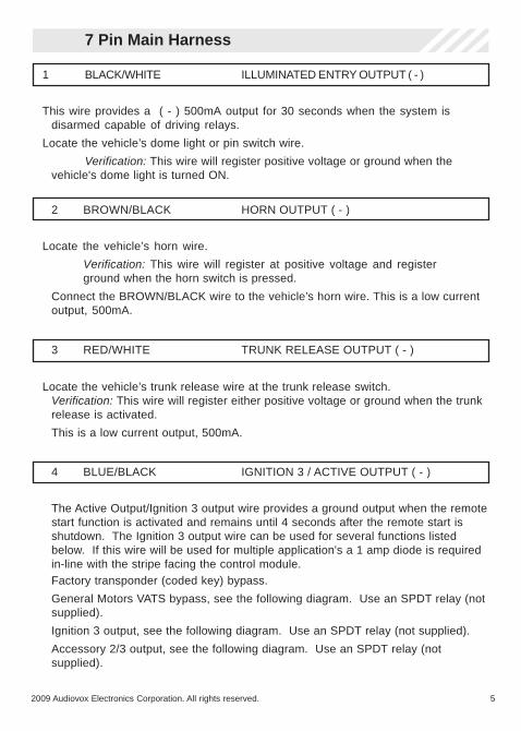
7 Pin Main Harness
1 BLACK/WHITE ILLUMINATED ENTRY OUTPUT ( - )
This wire provides a ( - ) 500mA output for 30 seconds when the system isdisarmed capable of driving relays.
Locate the vehicle’s dome light or pin switch wire.
Verification: This wire will register positive voltage or ground when thevehicle's dome light is turned ON.
2 BROWN/BLACK HORN OUTPUT ( - )
Locate the vehicle’s horn wire.
Verification: This wire will register at positive voltage and registerground when the horn switch is pressed.
Connect the BROWN/BLACK wire to the vehicle’s horn wire. This is a low currentoutput, 500mA.
3 RED/WHITE TRUNK RELEASE OUTPUT ( - )
Locate the vehicle’s trunk release wire at the trunk release switch.Verification: This wire will register either positive voltage or ground when the trunkrelease is activated.
This is a low current output, 500mA.
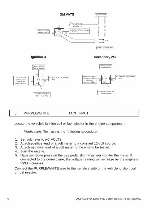
4 BLUE/BLACK IGNITION 3 / ACTIVE OUTPUT ( - )
The Active Output/Ignition 3 output wire provides a ground output when the remotestart function is activated and remains until 4 seconds after the remote start isshutdown. The Ignition 3 output wire can be used for several functions listedbelow. If this wire will be used for multiple application's a 1 amp diode is requiredin-line with the stripe facing the control module.Factory transponder (coded key) bypass.
General Motors VATS bypass, see the following diagram. Use an SPDT relay (notsupplied).
Ignition 3 output, see the following diagram. Use an SPDT relay (not supplied).
Accessory 2/3 output, see the following diagram. Use an SPDT relay (notsupplied).
6 2009 Audiovox Electronics Corporation. All rights reserved.
5 PURPLE/WHITE TACH INPUT
Locate the vehicle’s ignition coil or fuel injector in the engine compartment.
Verification: Test using the following procedure:
1. Set voltmeter to AC VOLTS.2. Attach positive lead of a volt meter to a constant 12-volt source.3. Attach negative lead of a volt meter to the wire to be tested.4. Start the engine.5. Have someone press on the gas pedal slightly as you monitor the meter. If
connected to the correct wire, the voltage reading will increase as the engine’sRPM increases.
Connect the PURPLE/WHITE wire to the negative side of the vehicle ignition coilor fuel injector.
Fused +12 VoltBattery Source
30
87
87a
86 85
BLUE/BLACK ActiveOutput Wire
VATS Control Module
Matching Value
Resistor
Ignition Switch
VATS
Wire
#1,
WH
ITE
or W
HIT
E/BL
ACK
VATS
Wire
#2,
WH
ITE
or V
IOLE
T/W
HIT
E
X CUT
GM VATS
Fused +12 VoltBattery Source
30
87
87a
86 85
BLUE/BLACK Active Output Wire
To Vehicle's 2nd or 3rd Ignition Wire
Jump To PINK Ignition Output Wire From Control Module
Ignition 3 Accessory 2/3
Fused +12 VoltBattery Source
30
87
87a
86 85
BLUE/BLACK Active Output Wire
To Vehicle's 2nd or 3rd Accessory Wire
Jump To ORANGE Accessory Output Wire From Control Module

72009 Audiovox Electronics Corporation. All rights reserved.
6 GRAY HOOD PIN INPUT ( - )
Install a Hood Pin Switch and connect to the GRAY wire. This connection isrequired for Remote Start.
Verification: This wire when connected will register ground when thevehicle's hood is opened.
Connect the GRAY wire to the hood pin.
NOTE: Be sure to loom the wire, and seal the grommet.
1 BLACK GROUND
Connect the BLACK wire to a solid chassis ground point using a ring terminal andself tapping screw (not supplied). Scrape away paint from the grounding point toensure a good connection. The recommended grounding point is a metal surfacein the driver’s side kick panel area.
NOTE: Do not ground the BLACK wire with any other vehicle components.
3 Pin Parking Light Harness
7 BROWN/RED BRAKE INPUT ( + )
Locate the vehicle’s brake light wire at the brake pedal mounted switch.
Verification: This wire registers positive voltage when the brake pedal ispressed.
Connect the BROWN/RED wire to the vehicle’s brake light wire.
2 WHITE/RED PARKING LIGHT INPUT
3 WHITE PARKING LIGHT OUTPUT
Locate the parking light output wire at the vehicle’s light switch.
Verification: This wire registers positive voltage when the parking lights areturned on.
Positive switching Parking Lights:
Connect the WHITE/RED wire to a 15 Amp max fused battery source.
Connect the WHITE wire to the parking light output wire.
Negative switching Parking Lights:
Connect the WHITE/RED wire to a good chassis ground.
Connect the WHITE wire to the parking light output wire.

8 2009 Audiovox Electronics Corporation. All rights reserved.
6 Pin Start Harness
1 PURPLE STARTER OUTPUT ( + )
Locate the vehicle starter wire.
Verification: This wire registers voltage only when the key is turned to theSTART position.
Verification:The starter wire registers voltage when the key is turned to theSTART position.
Connect the PURPLE wire to the vehicle starter wire.
2 RED BATTERY 12V ( + )
Locate 1 of the vehicle’s constant 12 Volt battery wires at the ignition switch.Verification: This wire will register ( + ) voltage in all positions of the ignitionswitch.
Connect the RED wire to the constant 12 Volt battery wire.
NOTE: Remove all fuses until all connections are made.
3 ORANGE ACCESSORY 1 ( + )
Locate the vehicle’s accessory wire at the ignition switch.
Verification: This wire registers voltage when the key is turned to ACC(Accessory) and the ON (or RUN) position. The voltage drops out when thekey is turned to the START (or CRANK) position.
Connect the ORANGE wire to the vehicle’s accessory wire.
4 PINK/WHITE IGNITION 2 ( + )
Locate the vehicle’s 2nd ignition wire at the ignition switch (if equipped).
Verification: This wire registers voltage when the key is turned to the ON (orRUN) position, but not the ACC (Accessory) position. The voltage does notdrop out when the key is turned to the START (or CRANK) position.
Connect the PINK/WHITE wire to the vehicle’s ignition 2 wire.
Programmable output: IGN, ACC, Start.
92009 Audiovox Electronics Corporation. All rights reserved.
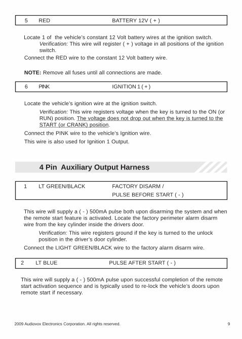
6 PINK IGNITION 1 ( + )
Locate the vehicle’s ignition wire at the ignition switch.
Verification: This wire registers voltage when the key is turned to the ON (orRUN) position. The voltage does not drop out when the key is turned to theSTART (or CRANK) position.
Connect the PINK wire to the vehicle’s Ignition wire.
This wire is also used for Ignition 1 Output.
5 RED BATTERY 12V ( + )
Locate 1 of the vehicle’s constant 12 Volt battery wires at the ignition switch.Verification: This wire will register ( + ) voltage in all positions of the ignitionswitch.
Connect the RED wire to the constant 12 Volt battery wire.
NOTE: Remove all fuses until all connections are made.
4 Pin Auxiliary Output Harness
1 LT GREEN/BLACK FACTORY DISARM /
PULSE BEFORE START ( - )
This wire will supply a ( - ) 500mA pulse both upon disarming the system and whenthe remote start feature is activated. Locate the factory perimeter alarm disarmwire from the key cylinder inside the drivers door.
Verification: This wire registers ground if the key is turned to the unlockposition in the driver’s door cylinder.
Connect the LIGHT GREEN/BLACK wire to the factory alarm disarm wire.
2 LT BLUE PULSE AFTER START ( - )
This wire will supply a ( - ) 500mA pulse upon successful completion of the remotestart activation sequence and is typically used to re-lock the vehicle’s doors uponremote start if necessary.
10 2009 Audiovox Electronics Corporation. All rights reserved.
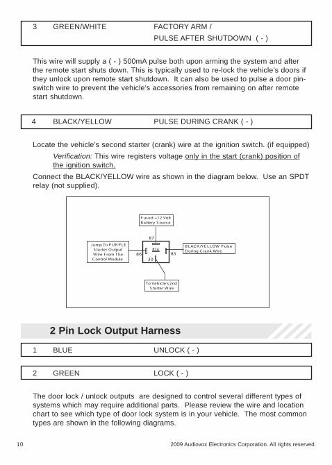
4 BLACK/YELLOW PULSE DURING CRANK ( - )
Locate the vehicle’s second starter (crank) wire at the ignition switch. (if equipped)
Verification: This wire registers voltage only in the start (crank) position ofthe ignition switch.
Connect the BLACK/YELLOW wire as shown in the diagram below. Use an SPDTrelay (not supplied).
F used +12 VoltB attery S ource
30
87
87a
86 85
B LAC K /Y E LLOW P ulseDuring C rank Wire
To Vehicle's2nd S tarter Wire
J ump To P UR P LE S tarter Output Wire From T he C ontrol Module
2 Pin Lock Output Harness
1 BLUE UNLOCK ( - )
2 GREEN LOCK ( - )
The door lock / unlock outputs are designed to control several different types ofsystems which may require additional parts. Please review the wire and locationchart to see which type of door lock system is in your vehicle. The most commontypes are shown in the following diagrams.
3 GREEN/WHITE FACTORY ARM /
PULSE AFTER SHUTDOWN ( - )
This wire will supply a ( - ) 500mA pulse both upon arming the system and afterthe remote start shuts down. This is typically used to re-lock the vehicle’s doors ifthey unlock upon remote start shutdown. It can also be used to pulse a door pin-switch wire to prevent the vehicle’s accessories from remaining on after remotestart shutdown.

112009 Audiovox Electronics Corporation. All rights reserved.
Negative Switching Locks
All Door Lock and Unlock: Locate the lock / unlock wire at the vehicle’s lock /unlock switch.
Verification: These wires will register ground when the Lock and Unlockswitches are activated.
Connect the GREEN and BLUE wires shown in the diagram below.
Lock
Unlock
Vehicle Door Lock Control Relays
GREEN (-) Lock Output
BLUE (-) Unlock Output
Negative Locks:
Positive Switching Locks
All Door Lock and Unlock: Locate the lock / unlock wire at the vehicle’s lock /unlock switch.
Verification: These wires will register positive voltage when the Lock andUnlock switches are activated.
Connect the GREEN and BLUE wires shown in the diagram below.
Lock
Unlock
87
87a86 85
30
87
87a86 85
30
Vehicle Door Lock Control Relays
Fused +12 Volt Battery Souce
Fused +12 Volt Battery Souce
GREEN (-) Lock Output
BLUE (-) Unlock Output
Positive Locks:

12 2009 Audiovox Electronics Corporation. All rights reserved.
Reverse Polarity Locks (5-Wire Door locks)
All Door Lock and Unlock: Locate the lock / unlock wire at the vehicle’s lock /unlock switch.
Verification: These wires will rest at ground and register positivevoltage when the Lock and Unlock switches are activated.
Connect the GREEN and BLUE or BLUE/GREEN wires shown in the diagrambelow using (2) SPDT relays (not supplied).
Lock
Unlock
87
87a86 85
30
87
87a86 85
30
Fused +12 Volt Battery Souce
Fused +12 Volt Battery Souce
GREEN (-) Lock Output
BLUE (-) Unlock Output
Reverse Polarity Locks:
XCut
XCut
To Door Lock Motor
To Door Lock Motor
Negative Multiplexed Locks
All Door Lock and Unlock: Locate the lock / unlock wire at the vehicle’s lock /unlock switch.
Verification: This wire will show variable ground when the switch is activated.Please consult the wire and location chart for specific resistor values foryour vehicle.
Connect the GREEN and BLUE or BLUE/GREEN wires shown in the diagrambelow using (2) SPDT relays (not supplied).
Lock
Unlock
Vehicle Door Lock Control Relays
GREEN (-) Lock Output BLUE (-) Unlock Output
Multiplex Locks:
87
87a86
30
87
87a86
30
85 85Fused +12 VoltBattery Source
Ground
Resistor

132009 Audiovox Electronics Corporation. All rights reserved.
Positive Multiplexed Locks
All Door Lock and Unlock: Locate the lock / unlock wire at the vehicle’s lock /unlock switch.
Verification: This wire will show variable positive voltage when the switch isactivated. Please consult the wire and location chart for specific resistorvalues for your vehicle.
Connect the GREEN and BLUE or BLUE/GREEN wires shown in the diagrambelow using (2) SPDT relays (not supplied).
Lock
Unlock
Vehicle Door Lock Control Relays
GREEN (-) Lock Output BLUE (-) Unlock Output
Multiplex Locks:
87
87a86
30
87
87a86
30
85 85Fused +12 VoltBattery Source
Resistor
Adding Aftermarket Actuators
After installing aftermarket actuators, (not supplied). Connect the GREEN andBLUE wires shown in the diagram below using (2) SPDT relays (not supplied).
30
87
87a
86 85
Fused +12 VoltBattery Source
Door Lock Actuator
30
87
87a
86 85
ChassisGround
ChassisGround
GREEN (-) Lock Output
BLUE (-) Unlock Output
Fused +12 VoltBattery Source
M
14 2009 Audiovox Electronics Corporation. All rights reserved.
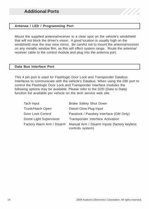
Data Bus Interface Port
This 4 pin port is used for Flashlogic Door Lock and Transponder DatabusInterfaces to communicate with the vehicle's Databus. When using the DBI port tocontrol the Flashlogic Door Lock and Transponder Interface modules thefollowing options may be available. Please refer to the D2D (Data to Data)function list available per vehicle on the tech service web site.
Tach Input Brake Safety Shut Down
Trunk/Hatch Open Diesel Glow Plug Input
Door Lock Control Passlock / Passkey Interface (GM Only)
Dome Light Supervision Transponder Interface Activation
Factory Alarm Arm / Disarm Manual Arm / Disarm Inputs (factory keylesscontrols system)
Antenna / LED / Programming Port
Mount the supplied antenna/receiver to a clear spot on the vehicle's windshieldthat will not block the driver's vision. A good location is usually high on thewindshield near the rear view mirror. Be careful not to mount the antenna/receiveron any metallic window film, as this will effect system range. Route the antenna/receiver cable to the control module and plug into the antenna port.
Additional Ports

152009 Audiovox Electronics Corporation. All rights reserved.
Manual Feature Programming - Feature Bank 2 - 4 chirps
1. Turn the ignition ON.
2. Press and hold the valet/override button.
3. Within 10 seconds the system will chirp (3) three times.
4. Use the valet/override button to advance through each option bank. Forfeature programming advance to Feature Bank 2, 3 or 4, which is (4) four, (5)five, and (6) six chirps.
5. Use the transmitter button to scroll through the selections in each featurebank, the system will chirp to match the feature number.
6. Press the transmitter button to change the desired feature. The LED willflash indicating the changed feature.
Defaulting All Features: Pressing the button anytime while in any of thefeature banks will default all features and return you to feature bank 2 - 4 chirps.
NOTE: The system will remain in feature programming mode as long as theignition is on, there is no time limit. To exit programming turn the IGNITION OFF.
Set Up & Programming
Transmitter Programming - Feature Bank 1 - 3 chirps
1. Turn the ignition ON.
2. Press and hold the valet/override button.
3. Within 10 seconds the system will chirp (3) three times.
4. Press 1 button of each transmitter you wish to program.
5. The system will respond with 1 chirp for each accepted transmitter.
6. Pressing the override button at anytime during programming will advance to thenext bank.
NOTE: The system will exit transmitter programming after 15 seconds of inactivity.
NOTE: This system has 1 button programming which programs all channels of thesystem.
NOTE: The system will hold up to 4 transmitters in memory, programming a 5thtransmitter will erase the oldest transmitter in memory.

16 2009 Audiovox Electronics Corporation. All rights reserved.
Feature Bank 1 - 3 ChirpsTransmitter Programming
Refer to transmitter programming.

172009 Audiovox Electronics Corporation. All rights reserved.
Tach Programming
The unit will not operate unless tach is programmed or tachless option isturned ON. If an attempt is made to start the vehicle via the remote start withoutfirst programming tach, the unit will flash the parking lights 7 times indicating tachhas not been learned and stored. If the tach rate is not properly programmed tothe specific vehicle, the unit may not realize that the vehicle is running in certaininstances and reengage the starter motor.
The Remote Start unit will learn the tach rate of most vehicle's single coil, multiple coilpacks, or single injector. To learn tach:
1. Turn the ignition key to the ON position.
2. Press and release the valet/override button 3 times.
3. Immediately turn the ignition key OFF.
4. Press and hold the valet/override button, then start the vehicle using thekey.
5. When the unit senses the tach signal, the parking lights will begin to flash.
6. Allow the vehicle to settle to a normal idle speed.
7. Release the valet/program push-button switch. The parking lights willturn on for 2 seconds indicating that the learned tach signal is stored andthe unit has exited tach learn mode.
NOTE: If the unit fails to learn tach rate due to an improper tach connection or apoor tach source, the parking lights will not flash. To correct this situation, locateand connect the PURPLE/WHITE wire to the proper tach signal, and then repeatthe tach learn routine.

18 2009 Audiovox Electronics Corporation. All rights reserved.
Feature Bank 2 - Security
1 - Silent Choice: Controls the normal arm/disarm chirps of the security system.
ON - Silent arming/disarming upon first press of lock/unlock, pressing lock/unlock a second time will activate the arm/disarm chirps respectively. Thesystem will only sound the arm/disarm chirps upon a second press of thelock/unlock buttons.
OFF - normal arm/disarm chirps upon the first press of lock/unlock.
Feature Descriptions
Feature Bank 3 - Output Control
1 - Extended Lock Pulse: Controls the timing of the BLUE and GREEN lock outputwires.
1 Second - Single 1 second lock pulse, single 1 second unlock pulse.
3.5 Seconds - Single 3.5 second lock pulse, single 3.5 second unlock pulse.
1 Second Lock, Double Pulse Unlock - Single 1 second lock pulse, double 1second unlock pulse.
30 Second Lock, Double Pulse Unlock - Single 30 second lock pulse, double1 second unlock pulse.
Double Pulse Lock, 1 Second Unlock - Double 1 second lock pulse, single 1second unlock pulse.
2 - Factory Disarm: Controls the timing of the LT. GREEN/BLACK factory disarmoutput.
Factory Disarm - Single 1 second pulse with unlock and remote startactivation.
2nd Unlock - Single 1 second pulse with 2nd press of unlock.
Start Status - Continuous ( - ) output during the remote start cycle.
192009 Audiovox Electronics Corporation. All rights reserved.
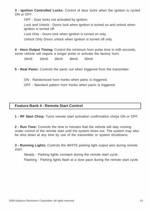
3 - Ignition Controlled Locks: Control of door locks when the ignition is cycledON or OFF.
OFF - Door locks not activated by ignition.
Lock and Unlock - Doors lock when ignition is turned on and unlock whenignition is turned off.
Lock Only - Doors lock when ignition is turned on only.
Unlock Only Doors unlock when ignition is turned off only.
4 - Horn Output Timing: Control the minimum horn pulse time in milli seconds,some vehicle will require a longer pulse to activate the factory horn.
16mS 10mS 30mS 40mS 50mS
5 - Real Panic: Controls the panic out when triggered from the transmitter.
ON - Randomized horn honks when panic is triggered.
OFF - Standard pattern horn honks when panic is triggered.
Feature Bank 4 - Remote Start Control
1 - RF Start Chirp: Turns remote start activation confirmation chirps ON or OFF.
2 - Run Time: Controls the time in minutes that the vehicle will stay runningunder control of the remote start until the system times out. The system may alsobe shut down at any time by use of the transmitter or system shutdowns.
3 - Running Lights: Controls the WHITE parking light output wire during remotestart.
Steady - Parking lights constant during the remote start cycle.
Flashing - Parking lights flash at a slow pace during the remote start cycle.

20 2009 Audiovox Electronics Corporation. All rights reserved.
4 - Tach Mode: Determines how the system monitors the engine running duringremote start.
Tach - Hard wired directly to the tach wire of the vehicle to monitor ACvoltage.
Tachless (Crank Average/Voltage) - Determines crank time by averaging thelast 8 times the vehicle was started with the key and then monitors thechange in voltage after remote start.
Hybrid (Crank Average / No Voltage) - Determines crank time by averagingthe last 8 times the vehicle was started with the key.
DBI Port - Monitors the vehicle’s tach rate through an interface moduleconnected to the DBI port.
5 - Voltage Level: The voltage variance for remote start when set to tachless.(see tach mode)
HIGH - The variance in battery voltage from before the remote startis activated to after the engine is running must be greater than 0.5 volts.
LOW - The variance in battery voltage from before the remote startis activated to after the engine is running may be less than 0.5 volts.
6 - Crank Time: Preset output times for the PURPLE starter wire.
1 Second 0.8 Seconds 1.5 Seconds 2 Seconds 4 Seconds
7 - Crank Average / Crank Time: The length of time in which the remote startwill crank the vehicle’s starter.
Crank Average - Determines crank time by averaging the last 8 times thevehicle was started with the key.
Preset Time - Preset starter output time. (see crank time)
8 - Gas / Diesel: Selects engine type and delay time for the starter output wireduring remote start activation.
Gas - Gasoline engine, no delay for the starter output wire.
10 Second Delay - Diesel engine, delays the starter output wire for 10seconds after the ignition has been powered up by the remote start.
15 Second Delay - Diesel engine, delays the starter output wire for 15seconds after the ignition has been powered up by the remote start.
20 Second Delay - Diesel engine, delays the starter output wire for 20seconds after the ignition has been powered up by the remote start.
45 Second Delay - Diesel engine, delays the starter output wire for 45seconds after the ignition has been powered up by the remote start.
212009 Audiovox Electronics Corporation. All rights reserved.
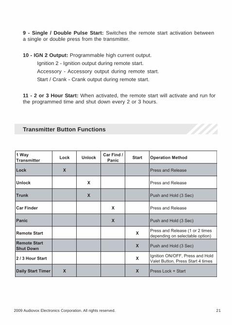
9 - Single / Double Pulse Start: Switches the remote start activation betweena single or double press from the transmitter.
10 - IGN 2 Output: Programmable high current output.
Ignition 2 - Ignition output during remote start.
Accessory - Accessory output during remote start.
Start / Crank - Crank output during remote start.
11 - 2 or 3 Hour Start: When activated, the remote start will activate and run forthe programmed time and shut down every 2 or 3 hours.
Transmitter Button Functions
22 2009 Audiovox Electronics Corporation. All rights reserved.
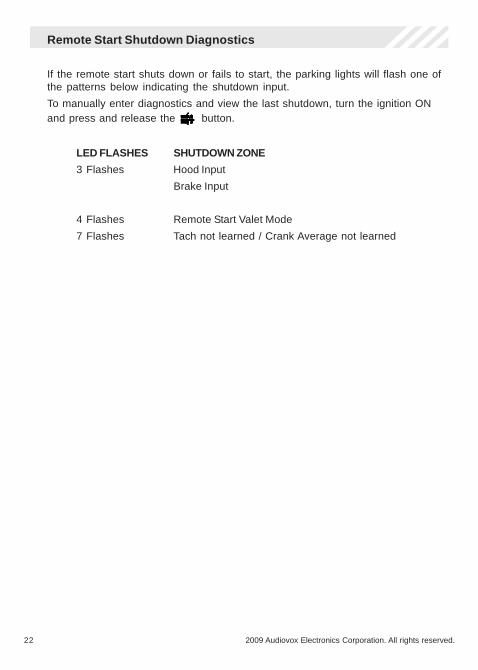
Remote Start Shutdown Diagnostics
If the remote start shuts down or fails to start, the parking lights will flash one ofthe patterns below indicating the shutdown input.
To manually enter diagnostics and view the last shutdown, turn the ignition ONand press and release the button.
LED FLASHES SHUTDOWN ZONE
3 Flashes Hood Input
Brake Input
4 Flashes Remote Start Valet Mode
7 Flashes Tach not learned / Crank Average not learned

232009 Audiovox Electronics Corporation. All rights reserved.
LT
GR
EE
N/B
LA
CK
FA
CT
OR
Y D
ISA
RM
/ P
UL
SE
BE
FO
RE
STA
RT
( -
)LT
BL
UE
PU
LS
E A
FT
ER
STA
RT
( -
)G
RE
EN
/WH
ITE
FA
CT
OR
Y A
RM
/ P
UL
SE
AF
TE
R S
HU
TD
OW
N (
- )
BL
AC
K/Y
EL
LO
W
PU
LS
E D
UR
ING
CR
AN
K (
- )
GR
EE
N
L
OC
K (
- )
BL
UE
UN
LO
CK
( -
)
PU
RP
LE
STA
RT
ER
OU
TP
UT
- M
OT
OR
SID
E (
+ )
RE
D
B
AT
TE
RY
12
V (
+ )
OR
AN
GE
AC
CE
SS
OR
Y 1
( +
)P
INK
/WH
ITE
IG
NIT
ION
2 (
+ )
RE
D
B
AT
TE
RY
12
V (
+ )
PIN
K
IG
NIT
ION
1 (
+ )
BL
AC
K
G
RO
UN
DW
HIT
E/R
ED
PA
RK
ING
LIG
HT
IN
PU
TW
HIT
E
P
AR
KIN
G L
IGH
T O
UT
PU
T
BL
AC
K/W
HIT
E
ILL
UM
INA
TE
D E
NT
RY
OU
TP
UT
( -
)B
RO
WN
/BL
AC
K
HO
RN
OU
TP
UT
( -
)R
ED
/WH
ITE
TR
UN
K R
EL
EA
SE
OU
TP
UT
( -
)B
LU
E/B
LA
CK
IG
NIT
ION
3 /
AC
TIV
E O
UT
PU
T (
- )
PU
RP
LE
/WH
ITE
TA
CH
IN
PU
TG
RA
Y
H
OO
D I
NP
UT
( -
)B
RO
WN
/RE
D
BR
AK
E I
NP
UT
( +
)
AN
TE
NN
AL
ED
VA
LE
T
DB
I P
OR
T
CA 5050

24 2009 Audiovox Electronics Corporation. All rights reserved.
Audiovox Electronics Corporation.
Customer Service 1-800-421-3209
WWW.CODE-ALARM.COM
FCC COMPLIANCE
This device complies with Part 15 of the FCC rules and with RSS-210 of
Industry Canada. Operation is subject to the following two conditions:
1. This device may not cause harmful interference, and
2. This device must accept any interference received, including any interferencethat may cause undesired operation.
Warning!
Changes or modifications not expressly approved by the party responsible for
compliance could void the user’s authority to operate the equipment.