Embed Size (px)
Citation preview
Remote Simulation
User Guide
MIKE 2017

2
PLEASE NOTE
COPYRIGHT This document refers to proprietary computer software which is pro-tected by copyright. All rights are reserved. Copying or other repro-duction of this manual or the related programmes is prohibited without prior written consent of DHI. For details please refer to your ‘DHI Software Licence Agreement’.
LIMITED LIABILITY The liability of DHI is limited as specified in Section III of your 'DHI Software Licence Agreement':
‘IN NO EVENT SHALL DHI OR ITS REPRESENTATIVES (AGENTS AND SUPPLIERS) BE LIABLE FOR ANY DAMAGES WHATSOEVER INCLUDING, WITHOUT LIMITATION, SPECIAL, INDIRECT, INCIDENTAL OR CONSEQUENTIAL DAMAGES OR DAMAGES FOR LOSS OF BUSINESS PROFITS OR SAVINGS, BUSINESS INTERRUPTION, LOSS OF BUSINESS INFORMA-TION OR OTHER PECUNIARY LOSS ARISING OUT OF THE USE OF OR THE INABILITY TO USE THIS DHI SOFTWARE PRODUCT, EVEN IF DHI HAS BEEN ADVISED OF THE POSSI-BILITY OF SUCH DAMAGES. THIS LIMITATION SHALL APPLY TO CLAIMS OF PERSONAL INJURY TO THE EXTENT PERMIT-TED BY LAW. SOME COUNTRIES OR STATES DO NOT ALLOW THE EXCLUSION OR LIMITATION OF LIABILITY FOR CONSE-QUENTIAL, SPECIAL, INDIRECT, INCIDENTAL DAMAGES AND, ACCORDINGLY, SOME PORTIONS OF THESE LIMITATIONS MAY NOT APPLY TO YOU. BY YOUR OPENING OF THIS SEALED PACKAGE OR INSTALLING OR USING THE SOFT-WARE, YOU HAVE ACCEPTED THAT THE ABOVE LIMITATIONS OR THE MAXIMUM LEGALLY APPLICABLE SUBSET OF THESE LIMITATIONS APPLY TO YOUR PURCHASE OF THIS SOFT-WARE.’
3

4 Remote Simulation - © DHI

CONTENTS
1 Introduction . . . . . . . . . . . . . . . . . . . . . . . . . . . . . . . . . . . . . . 7
2 System’s Overview . . . . . . . . . . . . . . . . . . . . . . . . . . . . . . . . . . 9
3 Client Component . . . . . . . . . . . . . . . . . . . . . . . . . . . . . . . . . . 113.1 Installing the Remote Simulation Console . . . . . . . . . . . . . . . . . . . . 113.2 Configuration of the Remote Simulation Console . . . . . . . . . . . . . . . . 11
3.2.1 Adding a server connection . . . . . . . . . . . . . . . . . . . . . . . 123.2.2 Edit a server connection . . . . . . . . . . . . . . . . . . . . . . . . 143.2.3 Delete a server connection . . . . . . . . . . . . . . . . . . . . . . . 153.2.4 Notification configuration . . . . . . . . . . . . . . . . . . . . . . . . 16
3.3 Using the Remote Simulation Console . . . . . . . . . . . . . . . . . . . . . . 183.3.1 Define a new simulation . . . . . . . . . . . . . . . . . . . . . . . . 183.3.2 Monitoring a simulation . . . . . . . . . . . . . . . . . . . . . . . . . 243.3.3 Controlling a simulation . . . . . . . . . . . . . . . . . . . . . . . . . 253.3.4 Getting the results . . . . . . . . . . . . . . . . . . . . . . . . . . . 263.3.5 Working with files on the server . . . . . . . . . . . . . . . . . . . . 263.3.6 Re-running simulations . . . . . . . . . . . . . . . . . . . . . . . . . 283.3.7 Removing legacy simulations . . . . . . . . . . . . . . . . . . . . . . 283.3.8 Grid customisation . . . . . . . . . . . . . . . . . . . . . . . . . . . 283.3.9 User- and Group Management . . . . . . . . . . . . . . . . . . . . . 293.3.10 Help . . . . . . . . . . . . . . . . . . . . . . . . . . . . . . . . . . . 483.3.11 Troubleshooting . . . . . . . . . . . . . . . . . . . . . . . . . . . . . 48
4 Server Components . . . . . . . . . . . . . . . . . . . . . . . . . . . . . . . . . 494.1 Installation . . . . . . . . . . . . . . . . . . . . . . . . . . . . . . . . . . . . 494.2 Using the Remote Simulation Administration Program . . . . . . . . . . . . . . 49
4.2.1 Setup of the application service . . . . . . . . . . . . . . . . . . . . 514.2.2 Setup of the data service . . . . . . . . . . . . . . . . . . . . . . . . 524.2.3 Setup of the feature service . . . . . . . . . . . . . . . . . . . . . . 53
4.3 Advanced Configuration . . . . . . . . . . . . . . . . . . . . . . . . . . . . . 564.3.1 Application service . . . . . . . . . . . . . . . . . . . . . . . . . . . 574.3.2 Feature service . . . . . . . . . . . . . . . . . . . . . . . . . . . . . 604.3.3 CPU clusters configuration . . . . . . . . . . . . . . . . . . . . . . . 684.3.4 The data service . . . . . . . . . . . . . . . . . . . . . . . . . . . . 70
4.4 Firewall Configuration . . . . . . . . . . . . . . . . . . . . . . . . . . . . . . 73
Index . . . . . . . . . . . . . . . . . . . . . . . . . . . . . . . . . . . . . . . . . . . . . 77
5

6 Remote Simulation - © DHI

1 Introduction
The MIKE Powered by DHI Remote Simulation is a tool that allows the user to easily transfer a model setup and computation to a remote computer. This implies that users can share a common and possible powerful computational resource and at the same time continue to work on their own PC’s without being hindered by running simulations. In short: having the MIKE Powered by DHI Remote Simulation installed on PCs in a corporate network enables the users to utilise and share computational power from a single powerful PC or a cluster.
This documentation is divided into three major parts:
1. A general overview of the components of the system.
2. A client part that relates to the component deployed on a user PC and the tools used for controlling and monitoring simulations running remotely.
3. A server part that deals with the server components that are deployed to a (typically) computational heavy duty PC and the configuration hereof.
7

Introduction
8 Remote Simulation - © DHI
2 System’s Overview
Seen from an overall perspective, the Remote Simulation system consists of a client part and a server part.
The client part contains components that allow users to connect and upload model setup to the server part. The server will then execute the engine relat-ing to the model. The server is able to handle different kinds of engines, known in this system as features.
It is the administrator of the server that configures which features are sup-ported.
9

System’s Overview
10 Remote Simulation - © DHI

Installing the Remote Simulation Console
3 Client Component
3.1 Installing the Remote Simulation Console
During the installation of MIKE Zero and MIKE URBAN, the Remote Simula-tion Console will automatically be installed. It is found as ‘DHI Remote Simu-lation Console’ in the Start menu. Alongside the short-cut to the console application you will also find references to this documentation and the release notes.
Note: Before you can make use of the Remote Simulation Console your sys-tem administrator must install and configure the server components, cf. 4.1 Installation (p. 49) and 4.2 Using the Remote Simulation Administration Pro-gram (p. 49).
3.2 Configuration of the Remote Simulation Console
The first time you launch the Remote Simulation Console, you need to config-ure it:
1. Go to ‘File → Options’.
2. In the ‘General’ tab, specify the default project folder, e.g. ‘C:\Data\MIKE Zero Projects’.
3. You may also change the default connection retry timeout. The default value is 60 seconds.
4. When you are submitting simulations to the server, the Remote Simula-tion console will analyse your setup for references to input files.Missing input files may render it impossible to execute the simulation. Input files, which are referenced, but missing in your setup, will cause a warning message to be displayed. Checking the “Ignore missing input file warn-ing” will disable these warning messages.
5. Now click the ‘Servers’ tab. Once a server is defined you can select a server and get the properties that relate to the selected server. This includes a list of the features it supports.
11

Client Component
Figure 3.1 Initial Options dialogue for Servers
3.2.1 Adding a server connection
To define a new server connection follow these few steps:
1. In the ‘File → Options’ ‘Servers’ tab, click ‘Setup’. This will open a dia-logue box where you can see the server connections defined for your PC.
Figure 3.2 Setup Server Connections dialogue
2. To add a new server click ‘Add’ and a new dialogue box appears
12 Remote Simulation - © DHI

Configuration of the Remote Simulation Console
Figure 3.3 Empty Add Server Connection dialogue
3. Now fill in the properties of the server connection
– ‘Server name:’ is a user friendly representation of the name of the server. It is used in the list of server connections.
– ‘Server address:’ is the network name of the server (as known by the domain name servers) or the IPv4 address of the server.
– ‘Port:’ is the port number. The default value is 5007.– The user name and password fields should be filled in with a user
name and password of a user configured in the system. These are supplied to you by the administrator, responsible for maintenance of the Remote Simulation Server that you are connecting to. Depend-ing on the server configuration, it may also be possible to use the “anonymous” profile. If you are the administrator, refor to the section on “User and Group management” for guidance on how to manage user accounts and groups.
– You may choose to test the connection by clicking the ‘Test’ button.
4. Complete the new connection by clicking ‘OK’ or click ‘Cancel’ to abort the addition.
Figure 3.4 Add Server Connection dialogue with specified server properties
13

Client Component
5. The server name should now be listed in the ‘Setup Servers Connec-tions’ dialogue shown in Figure 3.2. Click ‘Close’ to return to the ‘Options’ dialogue.
6. Click ‘OK’ to close the ‘Add Server Connection’ dialogue.
Note: If the connection to the server fails it will not be added.
After adding a server connection, a list of features for the selected server can be seen in the ‘Options’ dialogue. In this case the supported feature of ‘Mike's monster PC’ is the full set of engines supported by Remote Simulation.
Figure 3.5 Options dialogue for Servers after addition of server
3.2.2 Edit a server connection
To edit an existing server connection, follow these few steps:
14 Remote Simulation - © DHI

Configuration of the Remote Simulation Console
1. In the ‘File → Options’ ‘Servers’ tab, click ‘Setup’. This will open a dia-logue box where you can see the server connections defined for your PC
Figure 3.6 Setup Server Connections dialogue showing existing server
2. Click the server connection and click ‘Edit’. A new dialogue box appears:
Figure 3.7 Edit Server Connection dialogue
3. Modify the parameters as required. Then click ‘OK’ to accept the changes, or ‘Cancel’ to abort.
3.2.3 Delete a server connection
To delete an existing server connection follow these few steps:
15
Client Component
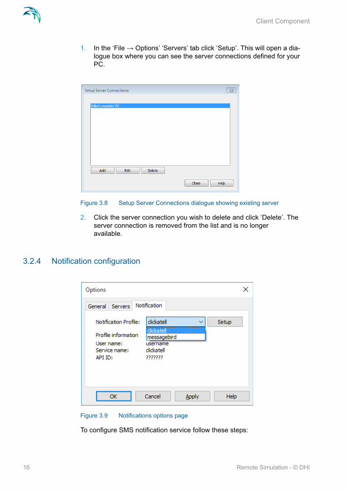
1. In the ‘File → Options’ ‘Servers’ tab click ‘Setup’. This will open a dia-logue box where you can see the server connections defined for your PC.
Figure 3.8 Setup Server Connections dialogue showing existing server
2. Click the server connection you wish to delete and click ‘Delete’. The server connection is removed from the list and is no longer available.
3.2.4 Notification configuration
Figure 3.9 Notifications options page
To configure SMS notification service follow these steps:
16 Remote Simulation - © DHI

Configuration of the Remote Simulation Console
1. In the 'File->Options' 'Notification' tab press 'Setup'. This will open a dia-logue box where you can see available profiles that can be used to send SMS notifications. clickatell and messagebird are pre-configured profiles.
Figure 3.10 List of SMS service profiles
2. [Select the profile you want to configure and press 'Edit'. A new dialogue box appears:
Figure 3.11 Edit notification profile – clickatell
17

Client Component
Figure 3.12 Edit notification profile – messagebird
3. Set the parameters based on your registration with the SMS service you want to use. Press 'OK' to save your changes.
3.3 Using the Remote Simulation Console
When a server connection is defined and verified as working, the Remote Simulation Console programme will contact the server, and populate the grid with information on available simulations defined in the system.
In the simulation menu, the user is able to define a new simulation and work with existing simulations. This section gives information on how to work with simulations in the Remote Simulation Console programme.
3.3.1 Define a new simulation
General
To define a new simulation follow these few steps:
18 Remote Simulation - © DHI

Using the Remote Simulation Console
1. Go to the menu Simulation → New. This will open the following dialogue box:
Figure 3.13 New Simulation dialogue
2. Enter the information for a simulation:
Use the button to browse to a model definition file. All files that are defined in the model setup and need to be sent to the server will be listed in the ‘Bundled files’ list. It is recommended to use the default file location for output files.
If the file includes a definition for a model that is not supported by the defined features in any of the existing server connections, the following dialogue box will be shown:
To solve this issue, a server connection that carries the needed features must be added, or the feature must be added to the server.
19

Client Component
Please note that not all MIKE engines are supported for Remote Simula-tion. Please consult the release note to learn which engines are sup-ported.
Enter a simulation name, The following characters are not allowed: *, ?, /, \ and : .
Choose a server to run the simulation. Only servers having all the required features can be selected.
3. Click ‘OK’ to close the dialogue box and start the upload of the simula-tion. The simulation will be queued according to rules defined by the sys-tem administrator.
Note: The Remote Simulation Console evaluates the input file and will try to locate all files referenced in the input file. If a file reference cannot be found a warning will be issued for each missing file. Most likely, this will happen if the output files are referenced at non-default locations. The input files can be uploaded but the simulation may fail.
Sharing your simulation
To define the users with whom you will share the simulation, navigate to the ‘Sharing’ tab.
20 Remote Simulation - © DHI

Using the Remote Simulation Console
Figure 3.14 New Simulation dialogue - sharing tab
The Remote Simulation software allows users to be defined and grouped in a hierarchy of
‘Units’ - designed to emulate companies, business units or departments
‘Groups’ - designed to emulate workgroups or project teams
‘Users’ - i.e. the individuals forming the workgroups or project teams
Users with whom the simulation is shared, will have full control of the simula-tion. This means that they will be able to view the properties of the simulation, as well as abort and delete it. Thus you should carefully consider if - and whom to share the simulation with.
In this tab you can choose to
Not share your simulation
Share with everyone (it will however still only be shared with users within the same ‘unit’)
Share the simulation with a specific group.
It is recommended to not share, or share only within your own workgroup.
Computational resources used for the simulation
To view and control the computational resources used for the simulation, nav-igate to the Resource Allocation Tab.
21

Client Component
Figure 3.15 New Simulation dialogue - Resource Allocation tab
The appearance of this dialogue will depend on:
The resources available on the server system that is used for the simula-tion
The computational engine that is used for the simulation
Some computational engines (such as the MIKE FM engines) are able to uti-lise several types of parallelisation as well as GPU (Graphical Processing Unit) cards. Others may be restricted to using 1 core per simulation.
The upper half of the dialogue displays general system information on the server environment on which the simulation is to take place. The terminology used reflects that Remote Simulation can be used on both full-scale HPC system (High Performance Computing) as well as on individual ‘Number crunchers’. Thus:
A ‘node’ is equivalent to a ‘single computer’. In a setup with a single number cruncher, this number will be 1. In an HPC setup, this number will be equal to the number of computing nodes that are allocated for Remote Simulation in the HPC system
A ‘core’ equals a single computational core on a computing node, whether this be a number cruncher or a computing node in an HPC sys-tem. Note that the Resource Allocation tab will show the number of phys-ical cores only - logical cores which are a result of hyperthreading being enabled are not shown
A GPU device is a GPU (Graphical Processing Unit) which is available for certain types of MIKE simulations
22 Remote Simulation - © DHI

Using the Remote Simulation Console
With the Resource Control tab, you will be able to control resources used for the simulation as per the table below:
You may choose to run the simulation
Exclusively on full node(s), or
Running on the first available set of cores
If you choose to ‘run exclusively’, the simulation is executed only when a full node is available - this even if there are cores available to run the simulation on the node. In a single number-cruncher configuration, the effects are that
The simulation will be queued until no other simulations are running on the number cruncher
Other simulations will be queued until the simulation has been completed
If you choose to ‘run on first available set of cores’, the simulation is queued until the necessary number of cores are available on the node/number cruncher. In the case where the previous simulation is running exclusively, the simulation will be queued until the previous simulation is complete.
The ‘Cancel launch if simulation has not started before’ and ‘Terminate simu-lation if not complete within’ options are presently reserved for use on HPC systems.
The Simulation may be submitted using the ‘OK’ button. Once submitted, the state of the simulation is updated automatically.
Table 3.1 Controlling resources
You would like to run The engine variant to choose
You can control Comments
A MIKE FM simulation on a machine with 1 GPU, using the GPU
GPU FemEngineHDGPU
The number of threads to use
1 GPU equals 1 subdomain only
A MIKE FM simulation on a machine with multiple GPU's, using these
MGPU FemEngineHDGPU
The number of GPU's to use (1 sub-
domain per GPU)
The system will by default use a number of threads equal to the number of cores available
A MIKE FM simulation using MPI
MPI FemEngineHD
Number of sub-domains equalling the number of MPI
processes
The system will use 1 thread per subdomain/process
A simulation based on an OpenMP enabled engine (e.g. model, MIKE SHE, MIKE 21C, MIKE 1D)
According to the engine chosen -
several are available
Number of threads to use for the simulation
- 1 core per thread
=
23

Client Component
Notification
To enable notifications sent when simulation changes its state, navigate to the ‘Notification’ tab. Enter e-mail address and/or cell phone number where you want to send notifications. Select a SMS profile that will be used to send SMS messages.Select what events trigger notifications: ‘Started’ when com-putation starts, ‘Completion’ when computation finishes, ‘Aborted by system’ when computation fails to start, and ‘Cancelled’ when computation is can-celled by a user.
Figure 3.16 New Simulation dialogue - notification tab
3.3.2 Monitoring a simulation
The state of a simulation can be monitored by looking in the ‘State’ column of the grid. To view the detailed properties of a simulation (whether running or completed),
1. Select the simulation in the grid
2. Go to the menu ‘Simulation → Properties’
24 Remote Simulation - © DHI

Using the Remote Simulation Console
Figure 3.17 Simulation Properties
You may also choose to download the log file of a simulation. This is done the following way:
1. Select one or more completed or running simulations in the grid.
2. Go to the menu ‘Simulation → View Log’.
3. The logs will be downloaded to the user PC and opened in a separate window.
3.3.3 Controlling a simulation
Depending on whether the engine is running, the user is allowed to abort one or more simulations.
Figure 3.18 Confirmation to abort a simulation
1. Select one or more running simulations in the grid.
2. Go to the menu ‘Simulation → Abort’ to bring the simulations to a halt.
25

Client Component
3. Confirm your action in the dialogue box. If more simulations are selected you can tick-mark “repeat action for the remaining simulations”.
3.3.4 Getting the results
When a simulation has been completed, you can download the result files from the server.
1. Select one or more running simulations in the grid.
2. Go to the menu ‘Simulation → Download’
3. Confirm your action in the dialogue box. If more simulations are selected you can tick-mark “repeat action for the remaining simulations”.
Figure 3.19 Confirmation to download results
The results are stored in a simulation specific folder under the project folder.
3.3.5 Working with files on the server
It is possible to manage files the server files of an already uploaded/com-pleted simulation. The following features are included:
View the folder/file structure of the simulation on the server
Upload of a subset of setup- and data files
Download of a subset of setu- and data files, including result files
This feature is in particular useful in cases where you need to simulate sev-eral scenarios with only minor variations in the setup, i.e. where only a small subset of the setup files change. In this case, a full upload of the setup is not strictly necessary. In such a case, you would typically:
1. Perform the simulation corresponding to your base scenario
2. Download the result files, to be stored separately
26 Remote Simulation - © DHI

Using the Remote Simulation Console
3. Make the necessary adjustments to the setup stored locally on your sys-tem
4. Upload the modified files
5. Re-run the simulation with the modified files
6. Download the results again for comparison with the base scenario
To access the file management features, you need to:
1. Select a completed simulation from the grid
2. In the ‘Simulation’ menu, choose ‘Files…’
The ‘Files’ dialogue is shown below:
Figure 3.20 File management dialogue
The left-most part of this window is a file-browser, which you can use to navi-gate the file/folder structure of the simulation on the server. Alternatively you may use the buttons for the following actions:
View: if a folder is chosen, opens this folder to view the contents. If a file is chosen, downloads the file and opens it using the program associated with the file. Double-clicking a folder/file in the folder view has the same effect
27

Client Component
Download: if a folder is chosen, pressing this will download all contents below this folder to your local system. If a file is chosen, the file chosen will be downloaded to your local system
Upload: An ‘open-file’ dialogue will be shown, allowing you to select one or more files on your local system to be uploaded to the server. Note that these are uploaded to the location on the server which was active when you pressed ‘Upload’, regardless of the folder structure.
New folder: Allows you to create a new folder on the server
Delete: If a folder is chosen, pressing this will delete the folder on the server and all contents below it. If a file is chosen, the chosen file will be deleted
Note: Caution should be shown when working with the file management fea-ture, as any changes to files and folders on the server are irreversible.
3.3.6 Re-running simulations
Should you wish to re-run a simulation (for example after uploading a change data/setup file), you may do so by
1. Selecting the simulation in the grid
2. Use the menu item ‘Simulation’ → ‘Run Again’
As any result files from earlier simulations are likely to be overwritten, you will be prompted to confirm.
3.3.7 Removing legacy simulations
1. Select one or more completed simulations from the grid.
2. Go to the menu ‘Simulation → Delete’ to remove the simulations from the grid.
3. Confirm your action in the dialogue box. If more simulations are selected you can tick-mark “repeat action for the remaining simulations”.
3.3.8 Grid customisation
It is possible to customise the grid holding the information of the simulations. You can select which fields you want included in the grid.
To modify the fields:
28 Remote Simulation - © DHI
Using the Remote Simulation Console
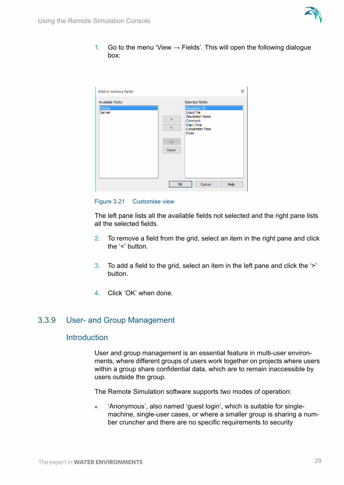
1. Go to the menu ‘View → Fields’. This will open the following dialogue box:
Figure 3.21 Customise view
The left pane lists all the available fields not selected and the right pane lists all the selected fields.
2. To remove a field from the grid, select an item in the right pane and click the ‘<’ button.
3. To add a field to the grid, select an item in the left pane and click the ‘>’ button.
4. Click ‘OK’ when done.
3.3.9 User- and Group Management
Introduction
User and group management is an essential feature in multi-user environ-ments, where different groups of users work together on projects where users within a group share confidential data, which are to remain inaccessible by users outside the group.
The Remote Simulation software supports two modes of operation:
‘Anonymous’, also named ‘guest login’, which is suitable for single-machine, single-user cases, or where a smaller group is sharing a num-ber cruncher and there are no specific requirements to security
29
Client Component
‘User/Group Management’, which is suitable in cases where multiple users and groups of users are sharing computational resources (number crunchers or an HPC), and security is a concern
The following sections explains how to get started with the Remote Simula-tion User / User Group management features.
Basic concepts (p. 30)Logging in as System Administrator (p. 31)Changing password of the user presently logged on (p. 31)Managing Units (p. 32)Creating a User (p. 34)Assigning a Unit Administrator (p. 36)Logging in as a Unit Administrator (p. 39)Managing Group memberships (p. 42)Logging in as a regular user (non-administrator) (p. 46)Viewing Properties of Units, Groups and Users (p. 47)Exporting and Importing Users (p. 47)Refreshing the view (p. 48)
Basic concepts
In the following, a ‘server environment’ denotes a machine, which hosts the Remote Simulation Application Service. Such an environment may be linked to several machines hosting the Remote Simulation Feature services. These are the machines hosting the computational engines and performing the sim-ulations. Thus in environment with several number crunchers, only one of these need to be configured with the Remote Simulation Application service.
Users and User Groups are defined per server environment. If you have sev-eral machines with the Application Service, Users and Groups need to be defined individually for each of these.
The User/Group management features are designed to allow sufficient flexi-bility to model most organizational structures, which are relevant in the con-text of Remote Simulation. The hierarchy consists of three (3) layers:
1. Unit (or Business Unit): Meant to emulate a business unit, such as a company, division or department
2. Group: Meant to emulate a group of staff working together, sharing data within the group but not necessarily outside the Group
3. User: The individual User, who is member of a Business Unit and possi-bly one or more groups
The server environment is created with a Unit named ‘System’. This Unit is intended for System Administration purposes only, and cannot be deleted. It
30 Remote Simulation - © DHI
Using the Remote Simulation Console
is possible, but not recommended, to add additional users to the System Unit. The System Unit is created with two users, which cannot be deleted:
admin: System Administrator user with full system privileges, including adding and managing Units
guest: generic, system-wide guest user, designed to ease the use of the system in ‘single-use’ cases or cases where no security is necessary
In addition, the server environment is created with an additional Unit, named ‘Company’. This is a standard unit, which is designed to ease the use of the user/group management features in cases where multiple users/groups are required, but there is no need for multiple Units. If this is the case you may simply log in as the company administrator to begin managing users and groups within the company unit. This is described in the section Logging in as a Unit Administrator (p. 39). If you do need to manage several Units, you should initially log in as system administrator.
Logging in as System Administrator
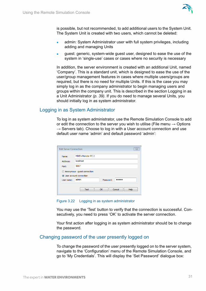
To log in as system administrator, use the Remote Simulation Console to add or edit the connection to the server you wish to utilise (File menu → Options → Servers tab). Choose to log in with a User account connection and use default user name ‘admin’ and default password ‘admin’:
Figure 3.22 Logging in as system administrator
You may use the ‘Test’ button to verify that the connection is successful. Con-secutively, you need to press ‘OK’ to activate the server connection.
Your first action after logging in as system administrator should be to change the password.
Changing password of the user presently logged on
To change the password of the user presently logged on to the server system, navigate to the ‘Configuration’ menu of the Remote Simulation Console, and go to ‘My Credentials’. This will display the ‘Set Password’ dialogue box:
31

Client Component
Figure 3.23 Set Password
To change the password, enter the old password (once) and new password (twice). To validate and commit the change, press the OK button, otherwise press ‘Close’. A confirmation message is displayed if the password update is successful.
Managing Units
To manage units and Groups, navigate to the menu item ‘Configuration’ of the Remote Simulation console, and choose ‘User Groups…’. This will display the ‘Configuration of User Groups’ window:
Figure 3.24 Configuration of User Groups
The picture above depicts the default users and groups, which are available on initial installation:
‘System’ Unit with the two groups:
– Administrators - including the system administrator user ‘admin’
32 Remote Simulation - © DHI

Using the Remote Simulation Console
– Guests - with the system-wide guest user ‘guest’
‘Company’ default group, with a single group of administrative users: ‘Administrators:Company’ with a single user ‘companyadmin’
Depending on the object selected in the tree view and your permissions, dif-ferent buttons will be enabled, and you may perform various actions.
To create a new Unit, press the ‘New unit...” button:
Figure 3.25 New Unit Creation
The information to be supplied reflects that ‘Units’ are designed to emulate business units (e.g. companies, branch offices or divisions). To create the new Unit press the ‘OK’ button. A confirmation message will be displayed if successful, and the new unit will be added to the tree view:
33

Client Component
Figure 3.26 Configuration of User Groups with new Unit added
The new Unit has been created with a single group of users: the group of Unit administrators. The unit is created without users and the group is therefore initially empty. The next step is to create and appoint an administrator of the new Unit. Start by pressing ‘Close’ to close the window.
Creating a User
To create a new user, access the ‘User Accounts…’ menu item from the Remote Simulation console menu ‘Configuration’. As users are created ‘per Unit’, you need to select the Unit to which the user should belong using the ‘Business Unit’ drop-down. In this example we will choose the recently cre-ated unit called ‘The Modeling Company’:
34 Remote Simulation - © DHI

Using the Remote Simulation Console
Figure 3.27 User Accounts
To create a new user, press the ‘New User’ button and fill in the necessary fields:
Figure 3.28 New User
To create the new user, press the OK button. A confirmation message will be displayed, and you will see the new user appearing in the ‘User Accounts’ window:
35

Client Component
Figure 3.29 User Accounts with new User
Press ‘Close’ to close the window and proceed to assigning the new user as an Administrator of the new Unit.
Assigning a Unit Administrator
To assign an administrator to a Unit, access the ‘User Groups’ dialogue from the ‘Configuration Menu’ of the Remote Simulation Console. To assign an administrator, select the Unit in question (here: ‘The Modeling Company’) and press the Administrators… button:
36 Remote Simulation - © DHI

Using the Remote Simulation Console
Figure 3.30 User Groups - selecting unit
A dialogue for management of memberships of the administrator group is dis-played:
Figure 3.31 Administrator Group members - showing non-member user
The left side (‘Users’) shows the list of members of the group.
The right side shows the available (non-member) users. Presently only the user ‘ModelingCompanyAdmin’ is available. To assign membership of the Administrators group, highlight the user in the right pane and press the ‘<’ button:
37

Client Component
Figure 3.32 Administrator Group members - showing membership
Then press ‘Close’ and verify in the tree view that the user appears in the list of administrators for the unit:
Figure 3.33 User Groups
You have now successfully worked as System Administrator to:
Configure a new Unit
Create a new User within the new Unit
Assign the new user administrative privileges within the new Unit
As such your initial tasks as system administrator are completed and respon-sibilities should be transferred to the administrative user within the new Unit.
38 Remote Simulation - © DHI

Using the Remote Simulation Console
Logging in as a Unit Administrator
Logging in as Unit Administrator is similar to logging in as any other user. In the Add/Edit server connections dialogue, simply choose the credentials of the Unit Administrator. If you are the Unit Administrator, the System Adminis-trator gives these to you. If you are using the system in its default setup with the built-in unit ‘Company’, you may login in with the credentials ‘companyad-min’ for both user name and password. You should continue by changing the password.
In this example, we will however use the credentials used in the previous examples:
Figure 3.34 Edit Server Connection
You may verify the credentials using the ‘Test’ button.
If successful, you may access the Configuration of User Groups window from the Configuration menu of the Remote Simulation Console:
39

Client Component
Figure 3.35 Configuration of User Groups
As a Unit Administrator, you will not be able to manage (create, view or mod-ify) units other than your own. However, you may:
Manage (including create and delete) Users within your own Unit
Manage (including create and delete) groups of users within your own Unit
Assign Administrators to groups, including assigning additional Unit Administrators
To create users, you may press the ‘Users’ button to access the ‘User Accounts’ dialogue. Alternatively this dialogue can be accessed from the ‘Configuration’ menu of the Remote Simulation Console by choosing ‘User Accounts’. Use the ‘New User’ feature to create the users that will be working within your Unit:
40 Remote Simulation - © DHI

Using the Remote Simulation Console
Figure 3.36 User Accounts
With the necessary users created, you may now press the ‘Create new Group’ button in the ‘Configuration of user Groups’ and fill in the necessary information to create a new Group:
Figure 3.37 New Group
Press the ‘OK’ button to create the Group. Repeat the process to create the groups that will be working in your Unit:
41

Client Component
Figure 3.38 Configuration of user Groups
The new groups are initially empty.
Managing Group memberships
With the necessary users and groups created within your Unit, you may access group membership management through:
‘Configuration of User Groups’ window, by pressing the ‘Users…’ button with the appropriate group selected
‘User Accounts’ window, by pressing the ‘Groups…’ button with the appropriate user selected
If accessed through ‘Configuration of User Groups’, choose the group to which you wish to add users and press ‘Users’:
42 Remote Simulation - © DHI

Using the Remote Simulation Console
Figure 3.39 Group Membership Management
Select the users you wish to add to the group in the ‘Others’ field and press the ‘<’ button:
Figure 3.40 Assigning Group membership
Consecutively, press the ‘Close’ button and verify the users have been added to the group:
43

Client Component
Figure 3.41 Users assigned to Groups
You may also access the feature from the ‘User Accounts’ window. In this window, select the user of interest and press ‘Groups…’
Figure 3.42 User Accounts - Groups
This will allow you to choose the groups to which the user should belong:
44 Remote Simulation - © DHI

Using the Remote Simulation Console
Figure 3.43 Group Memberships
Press the ‘<’ button to include the user in the selected group, and ‘Close’ to close the Window. Repeat the process as necessary.
Note: You may remove the user from the group by using the ‘>’ button.A user may be assigned memberships of several groups if necessary.
You may verify the memberships in the ‘Configuration of User Groups’ win-dow:
Figure 3.44 Configuration of User Groups
45

Client Component
Logging in as a regular user (non-administrator)
Logging in as a regular user takes place through the Add/Edit server connec-tions dialogue. Simply use the credentials provided to you by your administra-tor:
Figure 3.45 Edit Server Connection
You may verify the credentials using the ‘Test’ button.
If successful, you may access the Configuration of User Groups window from the Configuration menu of the Remote Simulation Console:
Figure 3.46 Configuration of User Groups
As a regular (non-administrative) user you may view the properties of your own Unit, as well as the properties of all groups and users in your unit. How-ever, the Unit- or System administrator must perform any necessary changes.
46 Remote Simulation - © DHI

Using the Remote Simulation Console
You may also submit simulations and choose to share these with the other members of the group(s) of which you are a member yourself. If you are a member of one group only, you can only share your simulation with no one, everyone or members of your own group.
Viewing Properties of Units, Groups and Users
To view the properties of a unit, group or user, access the Configuration of User Groups window or the User Accounts window. Select the unit/group or user of interest and press Properties:
Figure 3.47 Viewing properties of a group
Exporting and Importing Users
As a System- or Unit administrator, you may export users for backup or potential later import in another system, by using the ‘Export’ button in the ‘User Accounts’ window. This will prompt you to specify an .xml file, to which your present users will be stored. Note that the export function concerns the user profile only - i.e. the hierarchy of units and groups is not exported.
Reversely, users in an exported .xml file may be imported using the Import button in the ‘User Accounts’ window.
Though readable, the .xml file format used for the user import/export is propri-etary and you should not attempt to modify the files.
47

Client Component
Refreshing the view
Several users may be working with the system and introduce changes to users and groups simultaneously. To update a window to reflect the current state, you may at any time in any window press the ‘Refresh’ button.
3.3.10 Help
Online help is available from the application.
1. Go to the menu ‘Help → Help Topics’.
2. An online help file is shown.
3.3.11 Troubleshooting
To help troubleshooting errors the Remote Simulation Console produces a log. This log can be viewed in the following way:
1. Go to the menu ‘View → Application Log’.
2. The application Notepad will open and show the log.
3. Save the log to a known location (e.g. the desktop) and e-mail it to the system administrator including a description of what went wrong.
48 Remote Simulation - © DHI

Installation
4 Server Components
The server components are basically three services with specific responsibilities in the Remote Simulation system:
the Application Service
the Feature Service
the Data Service
This Chapter describes how to install and configure these server compo-nents.
4.1 Installation
The Remote Simulation Server Components are bundled into the MIKE Zero and MIKE URBAN installers. In order to install the components, you will have to run the appropriate installer and choose a custom installation type. In the features selection list of the installer, scroll down and select the ‘Remote Sim-ulation Server Components’ and follow the instructions given by the installer. During installation, three services will be installed in the disabled state. To ease the configuration of these services, a simple tool called ‘Remote Simu-lation Administration’ is also installed.
4.2 Using the Remote Simulation Administration Program
An administration tool is installed to make the configuration process easier. You start the tool by selecting ‘DHI Remote Simulation Administration’ from the Start menu. Or you can just search for 'DHI Remote Simulation Adminis-tration' application. The administration tool will create configuration files that can be immediately used. Figure 4.1 shows a message notifying that the default configuration is about to be created.
49

Server Components
Figure 4.1 Notification - Default Configuration Files
By default, all the services are installed in the disabled state. This allows you to configure the services before they are run, but also gives you the liberty to run the services on more computer systems at the same time.
Figure 4.2 Remote Simulation Administration interface
When you enable a service it will automatically start up the next time the server starts. The user is warned about this in a dialogue box. Figure 4.3 shows the 'Application Service' dialogue, but they all provide the same func-tionality.
50 Remote Simulation - © DHI

Using the Remote Simulation Administration Program
Figure 4.3 Enabling the Application service
If you choose 'No', the service will remain in disabled state. If you select 'Yes' the service in question will be set in the 'Automatic' startup state, It will only start when the server has been rebooted. By enabling a service, access is given to the 'Setup' dialogue and to viewing the log - you are able to start, stop, and restart the service.
4.2.1 Setup of the application service
Clicking the Setup button brings up the ‘Application Service Setup’ dialogue as shown in Figure 4.4.
Figure 4.4 Application Service Setup interface
The Network Interface parameter defines the Local network interface of the Application that you want to listen on. It can be an IP or domain address. 0.0.0.0 should be used in order to listen on all available IPv4 network inter-faces.
51

Server Components
The Port parameter defines the TCP port number. This service is listening for incoming requests from clients.
Application service must know what type of license has been granted to the system. It can be either 'Corporate License' or 'Public License'. 'Public License' is reserved to be used with HPC public services published by DHI.
The Dataset File Name defines the name of the database file that is used to store service data. The data file is created in the configuration directory (see Advanced Configuration (p. 56)).It is recommended to use the default value.
The Feature Servers Updates value defines delay in seconds between con-secutive feature server checks. It is recommended to use the default value.
'Anonymous' and 'System' check boxes enable correspondent authentication systems. At least one authentication system must be enabled.
The Feature Service grid defines the feature services connected to this appli-cation service. In this case we have defined a feature service named 'nomad' that is located at the host address 'nomad.subnet.com' and the communica-tion takes place on port 5005. More feature services may be defined in a sim-ilar fashion.
When changes are made to the fields, the 'OK' and 'Apply' buttons are ena-bled. If you click 'OK' or 'Apply' while the service is running, you will be asked if you want to apply the changes now.
Figure 4.5 Notification for applying changes
Selecting 'Yes' will stop the service, changes will be saved, and the service will be restarted. Clicking 'No' will roll back the changes. This behaviour is the same for the configuration of all three services.
Detailed configuration options can be found in Section 4.3.1.
4.2.2 Setup of the data service
Clicking the Setup button brings up the ‘Data Service Setup’ dialogue as shown in Figure 4.6.
52 Remote Simulation - © DHI

Using the Remote Simulation Administration Program
Figure 4.6 Data Service Setup interface
The Network Interface parameter defines which Local network interface to lis-ten on. It can be an IP or domain address. 0.0.0.0 should be used in order to listen on all available IPv4 network interfaces
The Port parameter defines the TCP port number. This service is listening for incoming requests from clients.
The Dataset File Name defines the name of the database file that is used to store service data. The data file is created in the configuration directory (see Advanced Configuration (p. 56)). It is recommended to use the default value.
The Base Data Storage Path defines a directory where data files are stored. Each simulation that is about to be run creates a subdirectory at this location, i.e. all simulations have their own ‘sandbox’ to save files. The directory is cre-ated in the base configuration directory. Therefore, it is recommended to install the Data and the Feature services on the same PC in a distributed setup. It is important that the feature service uses the same directory for ‘basedatastoragepath’. It is recommended to use the default value.
The Application Server parameters define the connection information of the application server that the data server belongs to.
When changes are made to the fields, the ‘OK’ and ‘Apply’ buttons are ena-bled. When you press ‘OK’ or ‘Apply’ while the service is running, you will be asked if you want to apply the changes now.
Selecting ‘Yes’ will stop the service, changes will be saved, and the service will be restarted. Clicking ‘No’ will roll back the changes.
4.2.3 Setup of the feature service
Clicking the Setup button brings up the ‘Feature Service Setup’ dialogue as shown in Figure 4.7.
53

Server Components
Figure 4.7 Feature Service setup interface
The Network Interface parameter defines the Local network interface to listen on. It can be an IP or domain address. 0.0.0.0 should be used in order to lis-ten on all available IPv4 network interfaces
The Port parameter defines the TCP port number. This service is listening for incoming requests from clients.
The Dataset File Name parameter defines the name of the database file that is used to store service data. The data file is created in the configuration directory (see Advanced Configuration (p. 56), typically it is C:\Program-Data\DHI\[release year]\RemoteSimulation). It is recommended to use the default value.
The Data Storage URL parameter defines the connection to the data storage defined by ‘basedatastoragepath’.
54 Remote Simulation - © DHI

Using the Remote Simulation Administration Program
The Data Storage Path parameter defines the directory where data files are stored. Each simulation that is about to be run creates a subdirectory to this location, i.e. all the simulations have their own ‘sandbox’ to store files. The directory is created in the configuration directory (see Advanced Configura-tion (p. 56)). It is important that the data service uses the same directory for ‘basedatastoragepath’. It is recommended to use the default value.
The Application Server Address parameter defines the Application Server DNS or IP address.
The Application Server Port parameter defines the TCP port number. This application service is listening for incoming requests from clients
The Data Server Address parameter defines the Data Server DNS or IP address.
The Data Server Port parameter defines the TCP port number. This data ser-vice is listening for incoming requests from clients.
To allow sending notification e-mails and/or SMS messages, SMTP and SMS service must be configured. E-mail configuration includes these fields: SMTP Server Address, SMTP over TLS, SMTP From E-mail Address, SMTP With Authentication, User and Password. Available profiles for SMS services are configured in the SMS Services table. Clickatell and messagebird profiles are pre-configured when Remote Simulation Server Components is installed.
The Features list defines which adaptors that are available to the user.
The Maximum parameter defines the maximum number of concurrent simula-tions running.
When changes are made to the fields, the ‘OK’ and ‘Apply’ buttons are ena-bled. If you press ‘OK’ or ‘Apply’ while the service is running, you will be asked if you want to apply the changes now.
Selecting ‘Yes’ will stop the service, changes will be saved, and the service will be restarted. Clicking ‘No’ will roll back the changes. This behav-iour is the same for the configuration of all three services.
Configuration of the adaptors
As part of the present release, you will find the following adaptors:
mzadaptor: targeting the engines of the MIKE Zero products in their default version
mzadaptor.mpi: targeting the engines of the MIKE Zero products, in their MPI version, if such exists.
55

Server Components
mzadaptor.gpu: targeting the engines of the MIKE Zero products, in their GPU (Graphical Processing Unit) version, if such exists. This requires a Tesla enabled GPU to be installed on the system hosting the feature service
mzadaptor.gpusp: targeting the engines of the MIKE Zero products, in their GPU (Graphical Processing Unit) Single Precision version, if such exists. This requires a Tesla enabled GPU to be installed on the system hosting the feature service
mzadaptor.mpigpu: targeting the engines of the MIKE Zero products, in their MPI + GPU (Graphical Processing Unit) version, if such exists. This requires a Tesla enabled GPU to be installed on the system hosting the feature service
mzadaptor.mpigpusp: targeting the engines of the MIKE Zero products, in their MPI + GPU (Graphical Processing Unit) Single Precision version, if such exists. This requires a Tesla enabled GPU to be installed on the system hosting the feature service
mouse: targeting the MOUSE engine for MIKE URBAN CS simulations
mike1d: targeting the MIKE1D engine for MIKE 11 and MIKE URBAN CS simulations
Note: Having more adaptors enabled and configured in the system, will cause ambiguity in relation to the type of engine that the system will choose to run the simulation. The system will select the adaptor where the ratio of running simulations versus the maximum number of simulation is the lowest.
4.3 Advanced Configuration
The configuration of the server components is not as straight forward as the configuration of the Client Component and will require capabilities and knowl-edge within the MIKE Powered by DHI software and system administration management.
Please do also keep in mind that Remote Simulation is a distributed system, which requires proper configuration of all its components.
In the most simple and typical corporate installation all three services are installed on one high performance server. More advanced configurations may have the services installed on a set of servers. However, only one application service should be configured in a system as it is able to communicate with more feature services installed on more servers. Each feature service requires a data service to be configured and running.
56 Remote Simulation - © DHI

Advanced Configuration
Each server that is running the feature service also runs the data service that allows upload and download of data for the feature service. Each server stores configuration files in the DHI\[releaseyear]\Remote Simulation folder in a common repository for application-specific data that is used by all users (typically it is C:\ProgramData, so the full path to the configuration directory would be C:\ProgramData\DHI\20xx\RemoteSimulation).
4.3.1 Application service
The ‘Application Service’ configuration defines the structure of the servers that are used to run the simulations. It also defines which authentication methods that are used to access the system as well as some internal param-eters. The Remote Simulation Console communicates with The Application Service to get access to the whole system of servers configured to run simu-lations.
dhiappsvc.xml
The dhiappsvc.xml configuration file defines the communication parameters for the Application Service. In the Service Control Manager it is named DHI Remote Simulation Application Service. The file defines the network inter-face(s) (network cards) and the port used to listen for connections from cli-ents. Furthermore, it defines how the Application Service manages communication with the clients. All configuration values are inside the /config-uration/applicationservice tag.
Figure 4.8 Example of the dhiappsvc.xml configuration file
<?xml version="1.0"?><configuration><applicationservice><networkinterface>0.0.0.0</networkinterface><port>5007</port><applicationtierinstance>applicationtier</applicationtierinstance><singlethreaded>0</singlethreaded><targetthreadcount>5</targetthreadcount><maxthreadcount>30</maxthreadcount><threadname>Application Server (RCF)</threadname><threadidletimeoutms>30000</threadidletimeoutms><license>corporate</license>
</applicationservice></configuration>
57

Server Components
The definitions of the various tags in the configuration file shown in Figure 4.8 are explained in Table 4.1.
applicationtier.xml
The applicationtier.xml configuration file defines the authentication methods used to access the system and a list of servers that are used to run simula-tions. All configuration values are inside the /configuration/applicationtier tag.
Table 4.1 Description of tags in the dhiappsvc.xml configuration file
Tag Description
networkinterface Local network interface to listen on. It can be an IP or domain address. 0.0.0.0 should be used in order to lis-ten on all available IPv4 network interfaces
port The TCP port number service is listening for incoming requests from clients
applicationtierinstance Application tier instance name. It is highly recommended to use the default value
singlethreaded Controls if the server should spawn threads to handle clients' requests - use value 0 here (recommended set-ting).
targetthreadcount Number of threads that are kept ready to handle clients' requests. It is highly recommended to use the default value
maxthreadcount Maximum number of threads that the server can create to handle clients' requests. It is highly recommended to use the default value
threadname Names the thread pool that manages the threads han-dling clients' requests. It is highly recommended to use the default value
threadidletimeoutms Defines how long threads are kept ready to be reused after they finish communication with a client. It is highly recommended to use the default value
license License type granted to the system. Allowed values are 'corporate' for corporate license and 'public' for public license.
58 Remote Simulation - © DHI

Advanced Configuration
Figure 4.9 Example of the applicationtier.xml configuration file
The definitions of the various tags in the configuration file shown in Figure 4.9 are explained in Table 4.2.
Table 4.2 Description of tags in applicationtier.xml configuration file
Tag Description
datasetfile The name of the database file that is used to store ser-vice data. A Data file is created in the configuration directory (see Advanced Configuration (p. 56)). It is rec-ommended to use the default value
updatefeatureservers-delay
Delay in seconds between consecutive feature server checks. It is recommended to use the default value.
authenticators Defines list of allowed authenticators to use for authenti-cation. It must contain one or more nested ‘authentica-tor’ tags. Only ‘anonymous’ is supported now (allows open access to the system).
authenticator Defines authenticator properties. It must contain a nested ‘name’ tag.
name Authenticator name. Allowed values are 'anonymous' and 'system'.
<?xml version="1.0"?><configuration><applicationtier><datasetfile>appdata.db</datasetfile><updatefeatureserversdelay>10</updatefeatureserversdelay><authenticators><authenticator>
<name>anonymous</name></authenticator><authenticator>
<name>system</name></authenticator>
</authenticators><featureservers><featureserver>
<name>Nomad</name><address>nomad.subnet.net</address><port>5005</port>
</featureserver><featureserver>
<name>HAL9K</name><address>hal9k.net</address><port>5005</port>
</featureserver></featureservers>
</applicationtier></configuration>
59

Server Components
4.3.2 Feature service
The ‘Feature Service’ configuration defines the list of available engines (fea-tures) that can be run through the server. The features are controlled by adaptors that need to be configured as well. It also defines which data the server uses, which application server it belongs to, and some internal param-eters. The Remote Simulation Console communicates with the Feature Ser-vice to run simulations, to get information on where input data should be saved, and where to get the simulation results.
dhifeaturesvc.xml
The dhifeaturesvc.xml configuration file defines the communication parame-ters of the Feature Service. In the Service Control Manager it is named DHI Remote Simulation Feature Service. The configuration file defines the net-work interface(s) (network cards) and the port used to listen for connections from clients. Furthermore, it defines how the Feature Service manages com-munication with clients. All configuration values are inside the /configura-tion/featureservice tag.
featureservers Defines feature servers that are used to run simulations. It must contain one or more nested ‘featureserver’ tags. All the feature servers must be running properly config-ured feature services
featureserver Defines information about the feature server. Contains ‘name’, ‘address’ and ‘port’ nested tags
name Unique feature server name
address Feature server DNS or IP address
port TCP port number of the feature service that is listening for incoming requests from clients
Table 4.2 Description of tags in applicationtier.xml configuration file
Tag Description
60 Remote Simulation - © DHI

Advanced Configuration
Figure 4.10 Example of dhifeaturesvc.xml configuration file
The definition of the various tags in the configuration file shown in Figure 4.10 is explained in Table 4.3.
Table 4.3 Description of tags in dhifeaturesvc.xml configuration file
Tag Description
networkinterface Local network interface to listen on. It can be IP or domain address. 0.0.0.0 should be used in order to lis-ten on all available IPv4 network interfaces
port TCP port number of the service that is listening for incoming requests from clients
featuretierinstance Feature tier instance name. It is highly recommended to use the default value
singlethreaded Controls if the server should spawn threads to handle clients' requests - use value 0 here (recommended set-ting).
targetthreadcount Number of threads that are kept ready to handle clients' requests. It is highly recommended to use the default value
maxthreadcount Maximum number of threads that the server can create to handle clients' requests. It is highly recommended to use the default value
threadname Names the thread pool that manages the threads han-dling clients' requests. It is highly recommended to use default value
threadidletimeoutms Defines how long threads are kept ready to be reused after they finish communication with a client. It is highly recommended to use default value
<?xml version="1.0"?><configuration><featureservice><networkinterface>0.0.0.0</networkinterface><port>5005</port><featuretierinstance>featuretier</featuretierinstance><singlethreaded>0</singlethreaded><targetthreadcount>5</targetthreadcount><maxthreadcount>30</maxthreadcount><threadname>Feature Server (RCF)</threadname><threadidletimeoutms>30000</threadidletimeoutms>
</featureservice></configuration>
61

Server Components
featuretier.xml
The featuretier.xml configuration file defines a list of adaptors and their con-figuration, and the list of features (engines) that can be used to run on the server. Furthermore, it defines which data server it uses, which application server it belongs to, and some internal parameters. All configuration values are inside the /configuration/featuretier tag.
Figure 4.11 Example of featuretier.xml configuration file
<?xml version="1.0"?><configuration><featuretier><datasetfile>featuretierdata.db</datasetfile><basedatastorageurl>rexdts://nomad.subnet.com/</basedatastorageurl><basedatastoragepath>sessions</basedatastoragepath><applicationserver><address>nomad.subnet.com</address><port>5007</port><secure>1</secure>
</applicationserver><dataserver><address>nomad.subnet.com</address><port>5009</port><secure>1</secure>
</dataserver><smtp><address>smtp://smtp-server.domain:25</address><authenticate>0</authenticate><user>0</user><password>0</password><fromemailaddress>0</fromemailaddress><tls>0</tls>
</smtp><textmessageservices><service><name>clickatell</name><format>http://api.clickatell.com/http/sendmsg?►
user=%USERNAME%&password=%PASSWORD%&api_id=%APIID%►&to=%DESTINATION%&text=%CONTENT%</format>
</service><service><name>messagebird</name><format>http://api.messagebird.com/api/sms?►
username=%USERNAME%&password=%PASSWORD%&►&destination=%DESTINATION%&body=%CONTENT%►&sender=%SENDER%</format>
</service></textmessageservices><clusters><cluster><name>default</name><parameters><parameter>:hosts=hosts.xml</parameter>
</parameters></cluster>
</clusters><adaptors><adaptor><name>mz</name><library>mzadaptor.dll</library><type>mzadaptor</type><parameters><parameter>:package=default</parameter><parameter>:cluster=default</parameter><parameter>$0</parameter><parameter>$1</parameter>
</parameters><implementedcategories/>
</adaptor>
<adaptor><name>mzmpi</name><library>mzadaptor.dll</library><type>mzadaptor.mpi</type><parameters><parameter>:package=default</parameter><parameter>:cluster=default</parameter><parameter>:mpiexec=►
C:\Program Files (x86)\IntelSWTools\►compilers_and_libraries_2016.0.110\windows\mpi\►em64t\bin\mpiexec.exe</parameter>
<parameter>-delegate</parameter><parameter>$0</parameter><parameter>$1</parameter>
</parameters><implementedcategories/>
</adaptor><adaptor><name>mouse</name><library>muadaptor.dll</library><type>mouse</type><parameters><parameter>:package=default</parameter><parameter>:cluster=default</parameter><parameter>$0</parameter><parameter>$1</parameter><parameter>$COMPUTATIONTYPE</parameter><parameter>RUN</parameter><parameter>CLOSE</parameter><parameter>SILENT</parameter><parameter>HIDDEN</parameter><parameter>SPI</parameter>
</parameters><implementedcategories/>
</adaptor></adaptors><features><feature><name>MZ</name><maxinstancecount>10000</maxinstancecount><adaptor>mz</adaptor>
</feature></features>
</featuretier></configuration>
62 Remote Simulation - © DHI

Advanced Configuration
The definition of the various tags in the configuration file shown in Figure 4.11 is explained in Table 4.4.
Table 4.4 Description of tags in featuretier.xml configuration file
Tab Description
datasetfile The name of the database file that is used for storing service data. The Data file is created in the configuration directory (see Advanced Configuration (p. 56), typically it is C:\ProgramData\DHI\[release year]\RemoteSimu-lation). It is recommended to use default value
basedatastorageurl URL that defines the connection to the data storage defined by ‘basedatastoragepath’. These protocols are supported at present:
* file - file path (e.g. to a shared folder)* rexdt - non-secure connection to a data server* rexdts - secure connection to a data server
It is important that users are allowed to access the stor-age using the connection defined here. If it is a shared folder, users must have appropriate access rights granted by the network administrator.
basedatastoragepath Defines a directory where data files are stored. Each simulation that is about to be run creates a subdirectory there, so all the simulations have their own ‘sandbox’ to store their files. The directory is created in the configura-tion directory (see Advanced Configuration). It is impor-tant that the data service uses the same directory for ‘basedatastoragepath’. It is recommended to use default value. See section 4.3.4.
applicationserver Defines the connection information of the application server that this feature server belongs to. Contains ‘address’, ‘port’ and ‘secure’ nested tags.
address Application server DNS or IP address
port TCP port number of the application service that is listen-ing for incoming requests from clients
secure Use 1 for a secure connection and 0 for a non-secure connection.
dataserver Defines the connection information of the data server that is used for uploading and downloading data files. Contains ‘address’, ‘port’ and ‘secure’ nested tags
address Data server DNS or IP address.
port TCP port number data service is listening for incoming requests from clients.
63

Server Components
secure Use 1 for a secure connection and 0 for a non-secure connection.
clusters Defines a list of CPU and GPU clusters with configura-tion about the amount of CPU and GPU available.
cluster Defines the configuration of one CPU+GPU cluster.
smtp Defines SMTP configuration that is used when server sends e-mail notifications.
address SMTP server address.
authenticate Use 1 if used SMTP server requires authentication. 0 if authentication is not used.
user User account used to authenticate with SMTP server.
password Pasword for the user account used to authenticate with SMTP server.
fromemailaddress E-mail address that is filled in the ‘’from’ field in e-mail notifications.
tls 1 to use secure TLS connection with SMTP server. 0 is used for non-secure connection.
textmessageservices Defines a list of SMS gateways that can be used to send SMS notifications.
Name SMS gateway service name.
Format Format of HTTP request used to send a SMS notifica-tion.
name Unique cluster name.
parameters Defines the configuration parameters of the cluster. It contains several nested 'parameter' tags.
parameter The configuration parameters of the cluster. Name of the host's configuration file (:hosts=hosts.xml) is expected.
clusters Defines a list of CPU and GPU clusters with configura-tion about the amount of CPU and GPU available.
cluster Defines the configuration of one CPU+GPU cluster.
name Unique cluster name.
parameters Defines the configuration parameters of the cluster. It contains several nested 'parameter' tags.
Table 4.4 Description of tags in featuretier.xml configuration file
Tab Description
64 Remote Simulation - © DHI

Advanced Configuration
parameter The configuration parameters of the cluster. Name of the host's configuration file (:hosts=hosts.xml) is expected.
adaptors Defines a list of adaptors and their configuration. It must contain one or more nested ‘adaptor’ tags. All the adap-tors must be properly configured or the feature service may fail to start.
adaptor Defines the configuration of one adaptor. It is possible to configure several adaptors of the same type.
name Unique adaptor name.
library The Library that implements the adaptor. All the adap-tors' libraries must be installed in the default MIKE Pow-ered by DHI ‘bin’ folder (C:\Program Files\DHI\20xx\bin, resp. C:\Program Files (x86)\DHI\20xx\bin). At present the MIKE 20xx includes the adaptor libraries mzadap-tor.dll and muadaptor.dll.
type Adaptor type. exeadaptor.dll (the only adaptor library available now) offers these adaptors:
* mzadaptor – runs MIKE Zero engines; it prefers 64bit binaries to run engines if they are installed, and runs 32bit binaries for the rest.* mzadaptor.mpi – runs MIKE Zero engines, it uses MPI and can run MPI enabled engines (64bit) only.* mzadaptor.gpu – runs GPU enabled engines, it uses a GPU for the engines supporting this feature. Requires a Tesla enabled GPU. Supports 64bit only.* mzadaptor.gpusp – runs GPU enabled engines (sin-gle precision), it uses a GPU for the engines supporting this feature. Requires a Tesla enabled GPU. Supports 64bit only.* mzadaptor.mpigpu – targeting the engines of the MIKE Zero products, in their MPI + GPU (Graphical Pro-cessing Unit) version, if such exists. This requires a Tesla enabled GPU to be installed on the host system.* mzadaptor.mpigpusp – targeting the engines of the MIKE Zero products, in their MPI + GPU (Graphical Pro-cessing Unit) Single Precision version, if such exists. This requires a Tesla enabled GPU to be installed on the host system.* mzadaptor.gpu – runs GPU enabled engines, it uses a GPU for the engines supporting this feature. Requires a Tesla enabled GPU. Supports 64bit only.*mouse – runs the MOUSE engine*mike1d – runs the mike1d engine
Table 4.4 Description of tags in featuretier.xml configuration file
Tab Description
65

Server Components
parameters Defines the configuration parameters of the adaptor. It contains several nested ‘parameter’ tags.
parameter The Configuration parameters of the adaptor:
mzadaptor expects these configuration parameters: name of the CPU cluster used to run the engine (:cluster=default), $0, $1 (as shown in Figure 4.11)
:cluster=default, $0, $1
mzadaptor.mpi expects these parameters: name of the CPU cluster used to run the engine (:cluster=default), full path to the mpiexec.exe execut-able (:mpiexec=c:\…\mpiexec.exe), additional option passed to mpiexec (-dele-gate), $0, $1 (see the example shown in Figure 4.11). TThe mza-daptor.mpi can be config-ured to run an MPI engines locally or distributed. Detailed configuration is provided in the host's con-figuration file
:cluster=default, :mpiexec=C:\Program Files (x86)\IntelSWTools\compil-ers_and_librar-ies_2017.0.109\windows\mpi\em64t\bin\mpiexec.exe, -delegate, $0, $1
mzadaptor.gpu expects these parameters: name of the CPU cluster used to run the engine (:clus-ter=default), run in physical console session on/off switch (:console=on/off), $0, $1
:cluster=default, :con-sole=off, $0, $1
mzadaptor.gpusp expects these parameters: name of the CPU cluster used to run the engine (:clus-ter=default), run in physical console session on/off switch (:console=on/off), $0, $1
:cluster=default, :con-sole=off, $0, $1
Table 4.4 Description of tags in featuretier.xml configuration file
Tab Description
66 Remote Simulation - © DHI

Advanced Configuration
parameter mzadaptor.mpigpu expects these parameters: name of the CPU cluster used to run the engine (:cluster=default), full path to the mpiexec.exe execut-able (:mpiexec=c:\…\mpiexec.exe), additional options passed to mpiexec, $0, $1 (see the example shown in Figure 4.11). The mzadap-tor.mpigpu can be config-ured to run an MPI engines locally or distributed. Detailed configuration is provided in the host's con-figuration file
:cluster=default, :mpiexec=C:\Program Files (x86)\IntelSWTools\compil-ers_and_librar-ies_2017.0.109\windows\mpi\em64t\bin\mpiexec.exe, $0, $1
mzadaptor.mpigpusp expects these parameters: name of the CPU cluster used to run the engine, full path to the mpiexec.exe executable (:mpiexec=c:\…\mpiexec.exe), additional options passed to mpiexec, $0, $1 (see the example shown in Figure 4.11). The mzadap-tor.mpigpusp can be config-ured to run an MPI engines locally or distributed. Detailed configuration is provided in the host's con-figuration file
:cluster=default, :mpiexec=C:\Program Files (x86)\IntelSWTools\compil-ers_and_librar-ies_2017.0.109\windows\mpi\em64t\bin\mpiexec.exe, $0, $1
mouse expects these parameters: name of the CPU cluster used to run the engine (:cluster=default), $0, $1, $COMPUTATION-TYPE, RUN, CLOSE, SILENT, HIDDEN, SPI
:cluster=default, $0, $1, $COMPUTATIONTYPE, RUN, CLOSE, SILENT, HIDDEN, SPI
mike1d expects these parameters: name of the CPU cluster used to run the engine (:cluster=default), $0, $1, -mz, -close
:cluster=default, $0, $1, -mz, -close
Table 4.4 Description of tags in featuretier.xml configuration file
Tab Description
67

Server Components
4.3.3 CPU clusters configuration
Detailed configuration for CPU/GPU clusters must be provided in its configu-ration file as described in a previous section (typically hosts.xml). This config-uration provides essential information about what CPU and GPU resources are available to use when running computational engines.
Figure 4.12 shows an example of the configuration file with one ’default’ clus-ter. Please note that the configuration values are inside the /configura-tion/hoststier tag. The definition of the various tags in the configuration file shown in Figure 4.12 is explained in Table 4.5.
All hosts defined in the configuration file must have access to the ‘basedata-storagepath’ described in Table 4.4.
implementedcategories Defines a list of the categories that the adaptor imple-ments. It gives additional information about the adaptor. It contains several nested ‘implementedcategory’ tags.
implementedcategory Category name that the adaptor implements.
features Defines a list of the features that the feature server pub-lishes to the clients. It must contain one or more nested ‘feature’ tags. All the features must be properly config-ured or the feature service may fail to start.
feature Defines configuration for one published feature.
name Unique feature name that is used to publish the feature.
maxinstancecount Maximum number of simultaneous simulations that can be running at one time. The Feature server rejects to run a simulation if the maximum number of simultaneous simulations has been reached.
adaptor Refers to an adaptor that is used to run and manage simulations. It must be the name of one of the configured adaptors (see above).
Table 4.4 Description of tags in featuretier.xml configuration file
Tab Description
68 Remote Simulation - © DHI

Advanced Configuration
Figure 4.12 Template of the mzadaptor.mpi configuration file (“hosts.xml”)
The definition of the various tags in the configuration file shown in Figure 4.12 is explained in Table 4.5.
Table 4.5 Description of tags in hosts.xml configuration file
Tag Description
clusters A list of clusters. It contains one or more nested ‘cluster’ tags.
cluster Defines information about CPU and GPU resources for one cluster. Cluster configuration contains ‘name’, ‘type’, ‘fastht’, ‘allowexclusive’ and ‘hosts’ nested tags.
name The name of the cluster.
type The type can either be ‘local’, where cluster has only one local host. It is ‘distributed’, where a number of remote hosts must be listed. ‘hybrid’ type allows both type of hosts (local and remote hosts).
<?xml version="1.0"?><configuration>
<hoststier><clusters>
<cluster><name>default</name><type>hybrid</type><fastht>0</fastht><allowexclusive>1</allowexclusive><forceexclusive>0</forceexclusive><hosts>
<host><address>nomad.subnet.com</address><enabled>yes</enabled><type>local</type><ncores>4</ncores><nlogicalprocessors>8</nlogicalprocessors><packages>
<package><name>1</name><homedir>C:\Program Files (x86)\►
DHI\2017\</homedir><win64bindir>bin\x64</win64bindir><win32bindir/><unixbindir/>
</package></packages>
</host>
<host><address>2-nomad.subnet.com</address><enabled>no</enabled><type>remote</type><ncores>4</ncores><nlogicalprocessors>4</nlogicalprocessors><gpu>1</gpu><packages>
<package><name>1</name><homedir>C:\Program Files (x86)\DHI\►
2017\</homedir><win64bindir>bin\x64</win64bindir><win32bindir/><unixbindir/>
</package></packages>
</host></hosts>
</cluster></clusters>
</hoststier></configuration>
69

Server Components
4.3.4 The data service
The Data Service configuration defines the data storage used for uploading and downloading files that are used to run the simulations or that are pro-duced during the simulation. It also defines which application server it belongs to and some internal parameters.
dhidatasvc.xml
The dhidatasvc.xml configuration file defines the communication parameters of the data service. In the Service Control Manager it is named DHI Remote Simulation Data Service. The file defines the network interface(s) (network cards) and the port used to listen for connections from clients. Furthermore, it
fastht Value ‘1’ if all logical processors should be used to run computational engines. Value ‘0’ if only CPU cores should be used. It is recommended to use value ‘0’ as engines don't get any gain from using all the logical pro-cessors.
allowexclusive Value ‘1’ to allow exclusive allocations of the whole hosts - even if not all CPU or GPU resources are used. Value ‘0’ otherwise.
hosts A list of hosts.
host Defines information about each host. Host configuration contains ‘address’, ‘enabled’, ‘type’, ‘ncores’, ‘nlogical-processors’ and ‘gpu’ nested tags.
address Host DNS or IP address
enabled ‘yes’ or ‘no’. If host is not enabled, it is not used to run any engine.
type Host (node) type. Value ‘local’ is used to identify hosts that are running feature service. ‘local’ hosts are able to run engines that do not support MPI (OpenMP engines, MOUSE). ‘remote‘ is used for all other hosts.
ncores The number of CPU cores on the host.
nlogicalprocessors The number of logical processors on the host. For sys-tems that have processors with Hyper-Threading Tech-nology, the number of logical processors is greater than number of CPU cores.
gpu The number of GPU devices on the host.
Table 4.5 Description of tags in hosts.xml configuration file
Tag Description
70 Remote Simulation - © DHI

Advanced Configuration
defines how the Data Service manages the communication with clients. All configuration values are inside the /configuration/dataservice tag.
Figure 4.13 Example of dhidatasvc.xml configuration file.
The definition of the various tags in the configuration file is shown in Figure 4.13 is explained in Table 4.6.
Table 4.6 Description of tags in dhiappsvc.xml configuration file
Tag Description
networkinterface The Local network interface to listen on. It can be an IP or domain address. 0.0.0.0 should be used in order to listen onlisten on all available IPv4 network interfaces
port TCP port number of the service that is listening for incoming requests from clients
datatierinstance Data tier instance name. It is highly recommended to use default value
singlethreaded Controls if the server should spawn threads to handle clients' requests - use value 0 here (recommended set-ting).
targetthreadcount Number of threads that are kept ready to handle clients' requests. It is highly recommended to use default value
maxthreadcount Maximum number of threads that server can create to handle clients' requests. It is highly recommended to use default value
threadname Names the thread pool that manages thread handling of client requests. It is highly recommended to use default value
threadidletimeoutms Defines how long threads are kept ready to be reused after they finish communication with a client. It is highly recommended to use default value
<?xml version="1.0"?><configuration><dataservice><networkinterface>0.0.0.0</networkinterface><port>5009</port><datatierinstance>datatier</datatierinstance><singlethreaded>0</singlethreaded><targetthreadcount>5</targetthreadcount><maxthreadcount>30</maxthreadcount><threadname>Data Server (RCF)</threadname><threadidletimeoutms>30000</threadidletimeoutms>
</dataservice></configuration>
71

Server Components
datatier.xml
The datatier.xml configuration file defines data storage used for uploading and downloading data files. The configuration file also defines which applica-tion server it belongs to, and some internal parameters. All configuration val-ues are inside the /configuration/datatier tag.
Figure 4.14 Example of the datatier.xml configuration file.
The definition of the various tags in the configuration file shown in Figure 4.14 is explained in Table 4.7.
Table 4.7 Description of tags in datatier.xml configuration file
Tag Description
datasetfile The name of the database file that is used to store the service data. The Data file is created in the configuration directory (see Advanced Configuration (p. 56)). It is rec-ommended to use default value
databasestoragepath Defines a directory where data files are stored. Each simulation that is about to be run creates a subdirectory there, so that all simulations have their own ‘sandbox’ to store their files. The directory is created in the configura-tion directory. It is important that the Feature service uses the same directory for ‘basedatastoragepath’. It is recommended to use default value. See Table 4.4
applicationserver Defines the connection information of the application server that the data server belongs to. Contains ‘address’, ‘port’ and ‘secure’ nested tags.
address Application server DNS or IP address
port TCP port number application service is listening for incoming requests from clients
secure Use 1 for a secure connection and 0 for a non-secure connection.
<?xml version="1.0"?><configuration><datatier><datasetfile>datatierdata.db</datasetfile><basedatastoragepath>sessions</basedatastoragepath><applicationserver><address>nomad.subnet.com</address><port>5007</port><secure>1</secure>
</applicationserver></datatier>
</configuration>
72 Remote Simulation - © DHI

Firewall Configuration
4.4 Firewall Configuration
As the server components in a typical configuration will receive simulation requests from client PCs running the Remote Simulation Console the firewall belonging to the server or servers running any of the server components of Remote Simulation will need to allow connections from those clients. The fol-lowing section describes how to configure the firewall on systems running the server components. The guide is written for Windows 7 or Windows Server 2008R2.
1. Open the Windows Firewall in the Control Panel and click ‘Advanced set-tings’.
2. In the window Windows Firewall with Advanced Settings, first click ‘Inbound Rules’ in the leftmost pane, next click ‘New Rule’ under actions in the rightmost pane.
3. Five steps need to be carried out to define the new rule in the ‘New Inbound Rule Wizard’.
– Choose the first step ‘Rule Type’ and select ‘Port’, click ‘Next’.
73

Server Components
– In the ‘Protocol and Ports’ step choose ‘TCP’ and specify the ports used by the system. If all three services are to run on this system, specify all three ports used. The default values are 5005, 5007 and 5009.
– In the ‘Action’ step choose ‘Allow the connection’.
74 Remote Simulation - © DHI

Firewall Configuration
– The Profile step lets you set the kind of networks from which you will allow connection.
– Finally, in step Name, give the rule a descriptive name.
75

Server Components
76 Remote Simulation - © DHI

INDEX
77

Index
Aadaptor . . . . . . . . . . . . . . . 65, 68adaptors . . . . . . . . . . . . . . . . 65address . . . . . . . . . 60, 63, 64, 70, 72allowexclusive . . . . . . . . . . . . . 70Application Service . . . . . . . . . 49, 57applicationserver . . . . . . . . . . 63, 72applicationtier.xml . . . . . . . . . . . 58applicationtierinstance . . . . . . . . . 58authenticate . . . . . . . . . . . . . . . 64authenticator . . . . . . . . . . . . . . 59authenticators . . . . . . . . . . . . . . 59
Bbasedatastoragepath . . . . . . . . . . 63basedatastorageurl . . . . . . . . . . . 63
Ccluster . . . . . . . . . . . . . . . . . . 64clusters . . . . . . . . . . . . . . . . . 64computational resources . . . . . . . . 21connection retry timeout . . . . . . . . 11controlling a simulation . . . . . . . . . 25
DData Service . . . . . . . . . . . . 49, 70databasestoragepath . . . . . . . . . . 72dataserver . . . . . . . . . . . . . . . 63datasetfile . . . . . . . . . . . . 59, 63, 72datatier.xml . . . . . . . . . . . . . . . 72datatierinstance . . . . . . . . . . . . . 71default file location . . . . . . . . . . . 19default project folder . . . . . . . . . . 11delete a server connection . . . . . . . 15dhiappsvc.xml . . . . . . . . . . . 57, 70dhifeaturesvc.xml . . . . . . . . . . . . 60
Eedit server connection . . . . . . . . . 14enabled . . . . . . . . . . . . . . . . . 70
Ffastht . . . . . . . . . . . . . . . . . . 70feature . . . . . . . . . . . . . . . . . 68Feature Service . . . . . . . . . . . 49, 60features . . . . . . . . . . . . . . . . . 68featureserver . . . . . . . . . . . . . . 60featureservers . . . . . . . . . . . . . 60
featuretierinstance . . . . . . . . . . . .61firewall configuration . . . . . . . . . . .73Format . . . . . . . . . . . . . . . . . .64fromemailaddress . . . . . . . . . . . .64
Ggpu . . . . . . . . . . . . . . . . . . . .70grid customisation . . . . . . . . . . . .28
Hhost . . . . . . . . . . . . . . . . . . . .70hosts . . . . . . . . . . . . . . . . . . .70
Iimplementedcategories . . . . . . . . .68implementedcategory . . . . . . . . . .68
Llibrary . . . . . . . . . . . . . . . . . . .65license . . . . . . . . . . . . . . . . . .58
Mmaxinstancecount . . . . . . . . . . . .68maxthreadcount . . . . . . . . 58, 61, 71monitoring a simulation . . . . . . . . . .24
NName . . . . . . . . . . . . . . . . . . .64name . . . . . . . . . . 59, 64, 65, 68, 69ncores . . . . . . . . . . . . . . . . . .70networkinterface . . . . . . . . 58, 61, 71new server connetion . . . . . . . . . .12new simulation . . . . . . . . . . . . . .18nlogicalprocessors . . . . . . . . . . . .70
Pparameter . . . . . . . . . 64, 65, 66, 67parameters . . . . . . . . . . . . . .64, 66password . . . . . . . . . . . . . . . . .64port . . . . . . . . . 58, 60, 61, 63, 71, 72
RRemote simulation console . . . . . . .11Remote Simulation Server Components .49removing legacy simulations . . . . . . .28
Ssecure . . . . . . . . . . . . . 63, 64, 72Server components . . . . . . . . . . .49
78 Remote Simulation - © DHI

Index
sharing simulation . . . . . . . . . . . . 20singlethreaded . . . . . . . . . . 58, 61, 71smtp . . . . . . . . . . . . . . . . . . . 64
Ttargetthreadcount . . . . . . . . 58, 61, 71textmessageservices . . . . . . . . . . 64threadidletimeoutms . . . . . . . 58, 61, 71threadname . . . . . . . . . . . 58, 61, 71tls . . . . . . . . . . . . . . . . . . . . 64troubleshooting . . . . . . . . . . . . . 48type . . . . . . . . . . . . . . . . . 65, 69
Uupdatefeatureserversdelay . . . . . . . 59user . . . . . . . . . . . . . . . . . . . 64
79

Index
80 Remote Simulation - © DHI


![Remote Large Data Visualization in the ParaView Framework · Remote Large Data Visualization in the ParaView ... I.3.1 [Computer Graphics]: Parallel Processing 1. Introduction Simulation](https://img.dokumen.tips/doc/110x75/5e9b3c92f2da8e59855c33a2/remote-large-data-visualization-in-the-paraview-framework-remote-large-data-visualization.jpg)