Embed Size (px)
Citation preview

8/3/2019 Remote Laser Vibrometry of Targets, Including Optically Camoulflaged Vehicles
http://slidepdf.com/reader/full/remote-laser-vibrometry-of-targets-including-optically-camoulflaged-vehicles 1/37
UNCLASSIFIED/UNLIMITED
Potential of Remote Laser Vibration Sensing for Military Applications
Peter Lutzmann, R. Frank, M. Hebel, R. EbertForschungsinstitut fuer Optronik und Mustererkennung (FGAN-FOM)
76275 Ettlingen, Gutleuthausstrasse 1, Germany
phone: +49 7243 992140
ABSTRACT
Coherent laser radar based vibration detection of remote object allows to measure vibration features of objects due to the high Doppler resolution. In particular vibration imagery offers a large potential for
short-range civil applications and for long-range target classification and identification including camouflaged or partly concealed targets. This technique allows also to discriminate between real targets
and decoys. Non-contacting acousto-optic buried land mine detection shows the potential of this attractivetechnique at short range. Sample vibration images were taken by laser radars at λ = 10.6 µm (CO2 laser)
and λ = 1.54 µm (erbium fiber laser) at ranges up to 3 km. Spatially unresolved targets were measured upto 40 km.
Keywords: vibrometry , vibration imagery, coherent laser radar
1.0 INTRODUCTION
For many years methods to classify and identify targets in the battlefield have been developed. There are
passive methods, e.g. evaluation of the thermal image of a target, and active methods, e.g. analysis of the
target radar echo. To prevent detection by a foe, passive or quasi passive procedures are preferred.
Acoustic or seismographic methods are extremely sensitive to the propagation medium or additional
battlefield effects and are therefore not very practical. Coherent laser radar is a method for measuring the
vibration signature of the target offering the following advantages:
• comparatively covert (owing to small divergence and the short dwell time)• high resolution (small wavelength)
• difficult to jam
• compatible with the current optical target detection sensors used on the battlefield
Click here to view PowerPoint presentation; Press Esc to exit

8/3/2019 Remote Laser Vibrometry of Targets, Including Optically Camoulflaged Vehicles
http://slidepdf.com/reader/full/remote-laser-vibrometry-of-targets-including-optically-camoulflaged-vehicles 2/37
Report Documentation PageForm Approved
OMB No. 0704-0188
Public reporting burden for the collection of information is estimated to average 1 hour per response, including the time for reviewing instructions, searching existing data sources, gathering and
maintaining the data needed, and completing and reviewing the collection of information. Send comments regarding this burden estimate or any other aspect of this collection of information,
including suggestions for reducing this burden, to Washington Headquarters Services, Directorate for Information Operations and Reports, 1215 Jefferson Davis Highway, Suite 1204, ArlingtonVA 22202-4302. Respondents should be aware that notwithstanding any other provision of law, no person shall be subject to a penalty for failing t o comply with a collection of information if it
does not display a currently valid OMB control number.
1. REPORT DATE
01 DEC 2005
2. REPORT TYPE
N/A
3. DATES COVERED
-
4. TITLE AND SUBTITLE
Potential of Remote Laser Vibration Sensing for Military Applications
5a. CONTRACT NUMBER
5b. GRANT NUMBER
5c. PROGRAM ELEMENT NUMBER
6. AUTHOR(S) 5d. PROJECT NUMBER
5e. TASK NUMBER
5f. WORK UNIT NUMBER
7. PERFORMING ORGANIZATION NAME(S) AND ADDRESS(ES)
Forschungsinstitut fuer Optronik und Mustererkennung (FGAN-FOM)
76275 Ettlingen, Gutleuthausstrasse 1, Germany
8. PERFORMING ORGANIZATION
REPORT NUMBER
9. SPONSORING/MONITORING AGENCY NAME(S) AND ADDRESS(ES) 10. SPONSOR/MONITOR’S ACRONYM(S)
11. SPONSOR/MONITOR’S REPORT
NUMBER(S)
12. DISTRIBUTION/AVAILABILITY STATEMENT
Approved for public release, distribution unlimited
13. SUPPLEMENTARY NOTES
See also ADM202015, Sensors and Sensor Denial by Camouflage, Concealment and Deception., The
original document contains color images.
14. ABSTRACT
15. SUBJECT TERMS
16. SECURITY CLASSIFICATION OF: 17. LIMITATION OF
ABSTRACT
UU
18. NUMBER
OF PAGES
36
19a. NAME OF
RESPONSIBLE PERSON a. REPORT
unclassified
b. ABSTRACT
unclassified
c. THIS PAGE
unclassified
Standard Form 298 (Rev. 8-98)
Prescribed by ANSI Std Z39-18

8/3/2019 Remote Laser Vibrometry of Targets, Including Optically Camoulflaged Vehicles
http://slidepdf.com/reader/full/remote-laser-vibrometry-of-targets-including-optically-camoulflaged-vehicles 3/37

8/3/2019 Remote Laser Vibrometry of Targets, Including Optically Camoulflaged Vehicles
http://slidepdf.com/reader/full/remote-laser-vibrometry-of-targets-including-optically-camoulflaged-vehicles 4/37
Potential of Remote Laser Vibration Sensing for Military Applications
With common laser radar systems used over longer ranges, the laser beam is spread across most, if not all, parts of the target. This results in spatially unresolved target vibration signatures. Frequency distributions
in the power spectra of such spatially unresolved vibration signatures are dependent on the area covered
by the laser beam on target and on target aspect angle. Our aim was to investigate to what extent the target
information content of the return signals would be increased by spatially resolving the vibration signature.
Resolution may be achieved by using a scan device or a multi-element receiver. With such a 2-
dimensional laser vibration sensing approach (vibration imagery) the target will be spatially resolved and
one obtains a “data cube” consisting of a 2D map of vibration amplitudes across the target, one for each
vibration frequency.
ideal Lambertian reflector
+ target reflectivity
− − − + atmospheric extinction
+ atmospheric extinctionand turbulence
1.5 µm laser radar system 10.6 µm laser radar system
ideal Lambertian reflector
+ target reflectivity
− − − + atmospheric extinction
+ atmospheric extinction
and turbulence
UNCLASSIFIED/UNLIMITED
Fig. 2: Available carrier to noise ratio (solid line) assuming two generic systems with
wavelengths of λ=1.5 µm and λ=10.6 µm.
In summary, the main purpose of vibration imagery is to
• understand the principle governing vibration signature formation
• model spatially unresolved vibration signatures
• study the enhancement of target classification
• study the capability of classifying concealed targets.

8/3/2019 Remote Laser Vibrometry of Targets, Including Optically Camoulflaged Vehicles
http://slidepdf.com/reader/full/remote-laser-vibrometry-of-targets-including-optically-camoulflaged-vehicles 5/37
Potential of Remote Laser Vibration Sensing for Military Applications
Fig 3: Visual pictures of the optical parts of the both laser radar systems
and their performance data
2.3 Point target vibration measurements
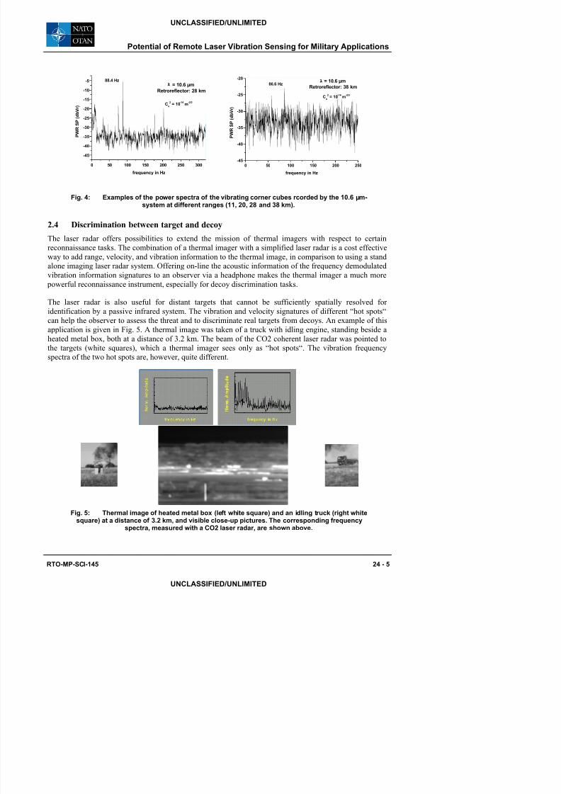
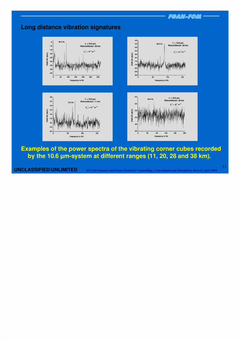
Figure 4 shows some examples of the power spectra after fm-demodulation of the received if-signal
detected from a modulated retro-reflector (diameter: 5”, modulation frequency range: 75 to 87 Hz) at
different ranges by the 10.6 µm laser radar system described above. The data sets here shown are analysed
on-line by an FFT-analyser. The occurrence of the other frequency components apart from the frequency
of the modulated corner cube may be due to contributions of vibrations induced by the retro-reflector shielding. Such effects had been identified in prior experiments with comparable data.
-25
-20
75.2 Hz
λ = 10.6 µm
Retroreflector: 11 km-50
-45
-40
89.6 Hzλ = 10.6 µm
Retroreflector: 20 km
UNCLASSIFIED/UNLIMITED
8/3/2019 Remote Laser Vibrometry of Targets, Including Optically Camoulflaged Vehicles
http://slidepdf.com/reader/full/remote-laser-vibrometry-of-targets-including-optically-camoulflaged-vehicles 6/37
0 50 100 150 200 250 300
-45
-40
-35
-30
-25
-20
-15
-10
-5
Cn
2= 10
-14m
-2/3
88.4 Hzλ = 10.6 µm
Retroreflector: 28 km
P W R S P ( d b V r )
frequency in Hz
0 50 100 150 200 250-45
-40
-35
-30
-25
-20
Cn
2= 10
-14m
-2/3
86.6 Hzλ = 10.6 µm
Retroreflector: 38 km
P W R S P ( d b V r )
frequency in Hz
Fig. 4: Examples of the power spectra of the vibrating corner cubes rcorded by the 10.6 µm-system at different ranges (11, 20, 28 and 38 km).
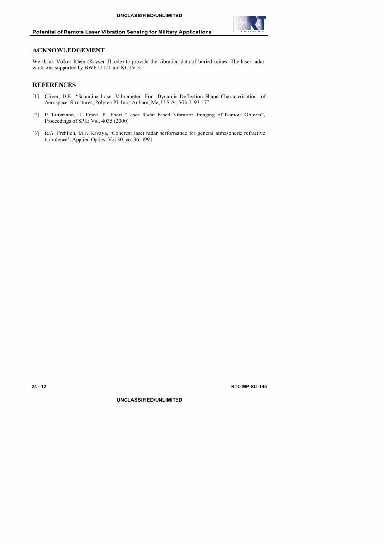
2.4 Discrimination between target and decoyThe laser radar offers possibilities to extend the mission of thermal imagers with respect to certain
reconnaissance tasks. The combination of a thermal imager with a simplified laser radar is a cost effective
way to add range, velocity, and vibration information to the thermal image, in comparison to using a stand
alone imaging laser radar system. Offering on-line the acoustic information of the frequency demodulated
vibration information signatures to an observer via a headphone makes the thermal imager a much more
powerful reconnaissance instrument, especially for decoy discrimination tasks.
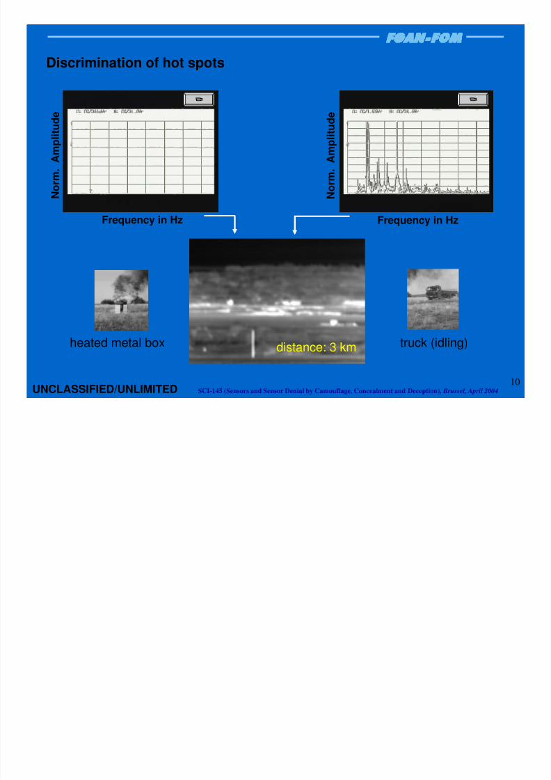
The laser radar is also useful for distant targets that cannot be sufficiently spatially resolved for identification by a passive infrared system. The vibration and velocity signatures of different “hot spots“
can help the observer to assess the threat and to discriminate real targets from decoys. An example of this
application is given in Fig. 5. A thermal image was taken of a truck with idling engine, standing beside a
heated metal box, both at a distance of 3.2 km. The beam of the CO2 coherent laser radar was pointed to
the targets (white squares), which a thermal imager sees only as “hot spots“. The vibration frequency
spectra of the two hot spots are, however, quite different.
UNCLASSIFIED/UNLIMITED
Potential of Remote Laser Vibration Sensing for Military Applications

8/3/2019 Remote Laser Vibrometry of Targets, Including Optically Camoulflaged Vehicles
http://slidepdf.com/reader/full/remote-laser-vibrometry-of-targets-including-optically-camoulflaged-vehicles 7/37
Potential of Remote Laser Vibration Sensing for Military Applications
2.5 Two dimensional vibration signaturesFigure 6 shows the visible image of a small truck and the 2d- vibration images under idling engine
condition at different frequencies. Data were recorded using the 1.54- laser radar sensor with a resolution
of 112 x 72 pixels at a range of 100 m.
Since any surface vibration of the target produces a micro Doppler shift of the reflected laser beam, it is
possible to place a vibrating target behind a partly obscuring screen (vegetation, smoke, camouflage net
etc.) and still detect the target and (partly) reconstruct the geometrical shape of the target. Analogously to
the well-known MTI (moving target indication) mode, this technique may thus be called VTI (vibrationtarget indication).
Camouflage nets often have many large or small holes, which are known to enforce thermal convection
and thus to assist the thermal camouflage behaviour. Laser beams can partly penetrate such nets and reach
the target surface, but the fractional area of the openings is not very high. So the laser return contains a
rather weak frequency modulated target return, plus a large but nearly unmodulated return from the net
itself.
In a first step, we used standard frequency demodulation algorithms which turned out to be quite
ineffective in dealing with a dominating backscatter at the IF frequency and the small Doppler-shifted
signal (co-channel interference with small-amplitude target vibrations). However, more sophisticated
algorithms can yield better detection of the contributing modulation from the vibrating target.
Figure 7, top and bottom, shows samples of raw data of a small civil truck, bare and camouflaged,
respectively. Data were recorded using the 10.6 µm- laser radar system with a resolution of 70 x 40 pixels
at a range of 400 m.
UNCLASSIFIED/UNLIMITED

8/3/2019 Remote Laser Vibrometry of Targets, Including Optically Camoulflaged Vehicles
http://slidepdf.com/reader/full/remote-laser-vibrometry-of-targets-including-optically-camoulflaged-vehicles 8/37
µm / sµm / s
Fig. 7: 2d vibration images of a small truck - bare and camouflaged - at the frequency of 30Hz; recorded by the 10.6 µm- laser radar at a resolution of 70x40 pixels in a range of 400 m,
along with the visible close-up picture.
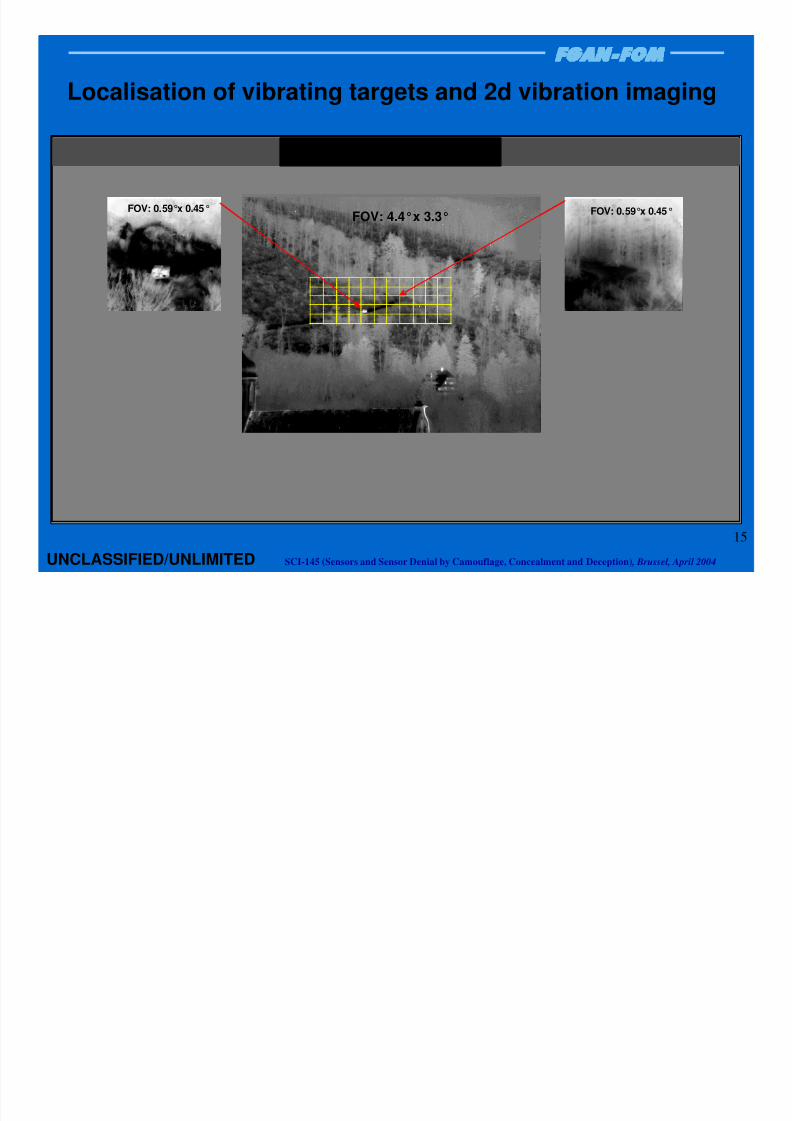
2.6 Localisation of vibrating targets and 2d vibration imaging
Laser radar systems are working with very small beam divergences in the order of hundred microradians
to some milliradians - due to their small wavelengths. Therefore laser radar systems, generally, are not
quite suitable for search mode applications. Operating a laser radar system in a search mode requests veryhigh pulse repetition rates or very high scanning rate to cover larger field of views. In some first
experiments, we have tried to employ the 1.5 µm-laser radar (vibration sensor) in a search mode, but only
for a pre-selected, narrow region of interest. An example of this application is given in Fig. 8
The thermal image at 3-5 µm shows a scene with a small truck and a camouflaged generator in about 3
km. The small truck is clearly seen whereas the camouflaged generator shows no striking cues – even with
a very small field of view (close-up thermal image at the top right corner). The issue of these
measurements was to demonstrate the possibility of the laser radar in order to detect and localise vibrating
targets within a region of interest which can be camouflaged and/or partially concealed.
First, the laser beam was scanned step by step with a coarse scan pattern over the region of interest where
some further objects are assumed to be placed. In this case the laser system is used in a search mode to a
certain degree. The spacing of 2 m between adjacent laser spots were adapted to the size of the objects
placed in the scene Only vibrating objects larger than 2 m could be found in the range of 3 km The
UNCLASSIFIED/UNLIMITED
Potential of Remote Laser Vibration Sensing for Military Applications

8/3/2019 Remote Laser Vibrometry of Targets, Including Optically Camoulflaged Vehicles
http://slidepdf.com/reader/full/remote-laser-vibrometry-of-targets-including-optically-camoulflaged-vehicles 9/37
Potential of Remote Laser Vibration Sensing for Military Applications
UNCLASSIFIED/UNLIMITED
Fig. 8: Localisation of vibrating targets and 2d- vibration imaging.

8/3/2019 Remote Laser Vibrometry of Targets, Including Optically Camoulflaged Vehicles
http://slidepdf.com/reader/full/remote-laser-vibrometry-of-targets-including-optically-camoulflaged-vehicles 10/37
(typical penetration depth 20-30 cm) and high dispersion. In case a mine or other inhomogeneity is present
below the soil surface the transmitted sound waves are scattered or reflected by the buried object. For
targets very close to the surface, the scattered field is even indicating shape and size of the buried object.
These surface vibration images are read out by the SLDV sensor, scanning the ground in a pre-
programmed pattern.
Fig. 9: SLDV basics and 3D structure of SLDV data.
The recorded vibration images and frequency spectra are characteristic for the type of mine (and different
for other buried objects such as stones). Such acoustic “fingerprints” are much more informative than
passive echoes. The SLDV technique is detecting metal mines as well as plastic mines (e.g. anti-
personnel), because it is absolutely independent from any metal content within a mine. With ground-
penetrating radar, objects embedded in the soil present a dielectric variation and cause a reflection of theelectromagnetic wave. This permits a 3D-mapping of the ground, but does not give specific frequency
“fingerprints” from objects as does the 2D-mapping by the SLDV.
In several successful field trials, different mines and other objects were investigated under the influence of
different types of soil (river gravel, loam, clay, sand or grass; including wet or moist soil conditions, being
less favourable).
One current drawback is the measurement time needed. A typical multispectral scan of 1 m2
takes about
8 minutes, depending on the selected spatial resolution, but improvements are already being investigatedusing detector arrays or dedicated predefined acoustic frequencies.
The recorded vibration images and frequency spectra are characteristic for the type of mine (and different
for other buried objects such as stones). The SLDV technique is detecting metal mines as well as plastic
mines (e.g. anti-personnel), since it is absolutely independent from any metal content within a mine.
UNCLASSIFIED/UNLIMITED
Potential of Remote Laser Vibration Sensing for Military Applications

8/3/2019 Remote Laser Vibrometry of Targets, Including Optically Camoulflaged Vehicles
http://slidepdf.com/reader/full/remote-laser-vibrometry-of-targets-including-optically-camoulflaged-vehicles 11/37
0 50 100 150 200 250
0
5
10
15
20
off target
on target
ATM
(8 cm deep in gravel)
v e l o c i t y i n µ m / s
frequency in Hz
0 200 400 600 800 1000
0
10
20
30
40
50
60
70
80
off target
on target
APM
(1 cm deep in ferromagnetic soil)
v e l o c i t y i n µ m / s
frequency in Hz
Figure 10: Spectral responses directly above the top of the ATM (8 cm deep in gravel) and theAPM (1 cm deep in ferromagnetic soil) and besides the mines (off target / background). Spectral
resolution: 5 Hz.
A presentation of a set of 2-dimensional intensity coded maps, showing the vibration intensities of the
individual measurement points in a dedicated intensity scale, of the same mines are given in figure 10.
Special smoothing and filtering can additionally be applied to enhance these visualisations. The maps seen
here are presenting data of two frequency bands for the ATM as well for the APM, based on an identical
geometrical scale. Besides the different frequency response, information about the size and shape of the
buried object were available. Of course, the possible determination of the shape and size are reduced by
less resolution of the grid (number of scanning points) and deeper buried objects.
UNCLASSIFIED/UNLIMITED
Potential of Remote Laser Vibration Sensing for Military Applications

8/3/2019 Remote Laser Vibrometry of Targets, Including Optically Camoulflaged Vehicles
http://slidepdf.com/reader/full/remote-laser-vibrometry-of-targets-including-optically-camoulflaged-vehicles 12/37
Potential of Remote Laser Vibration Sensing for Military Applications
UNCLASSIFIED/UNLIMITED
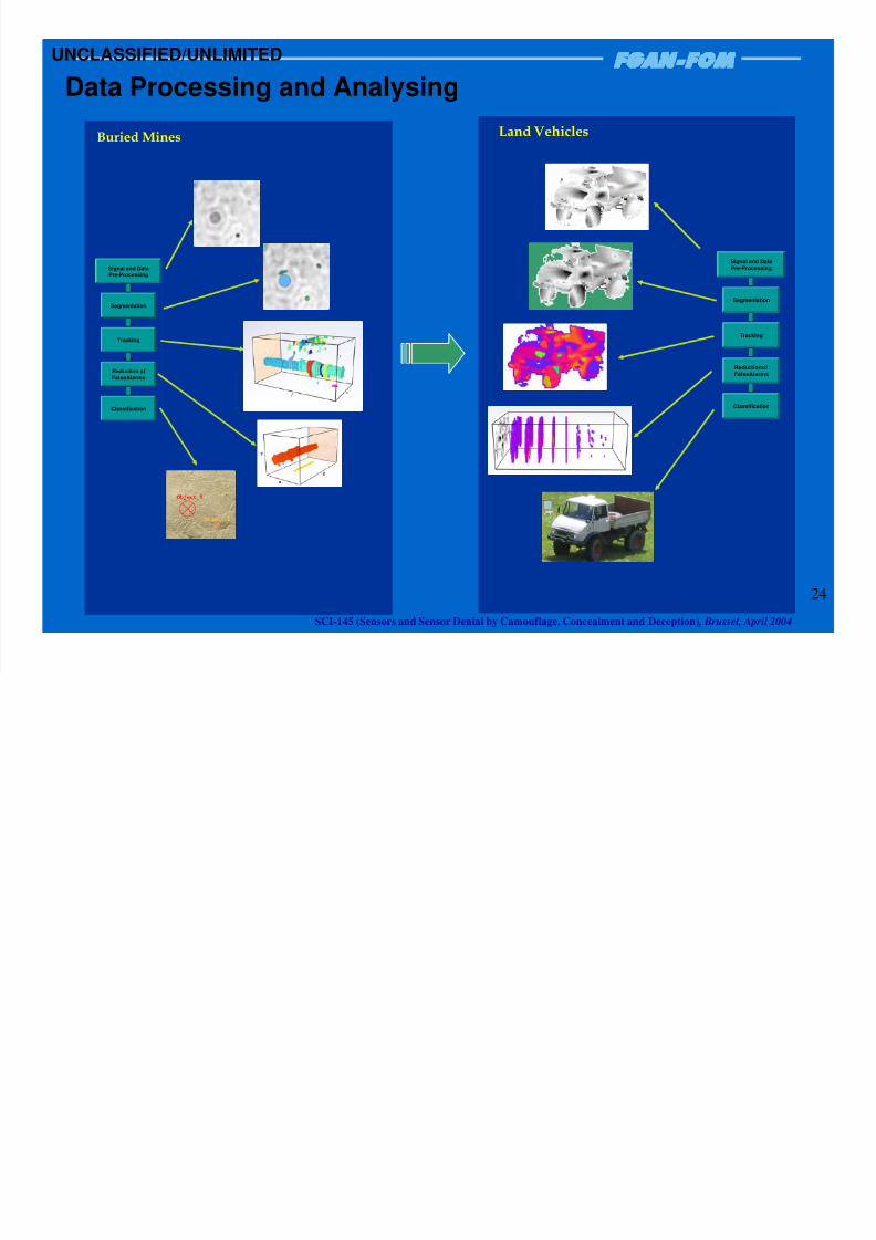
4.0 DATA PROCESSING AND ANALYSINGThe data processing and analyzing were developed for the mine detection and classification. This
technique will be also used to investigate the classification of vibrationg land vehicles (stationary and/or
driving). Fig. 12 shows the hierarchical data processing scheme ranging from the preprocessing,
segmentation using a multi-threshold algorithm for the segmentation of cues and reduce false alarms by
analyzing the stability of object size, contrast and shape in the frequency domain, feature extraction and
classification.
Fig. 12: The hierarchical data processing scheme for classifying buried mines and landvehicles.
8/3/2019 Remote Laser Vibrometry of Targets, Including Optically Camoulflaged Vehicles
http://slidepdf.com/reader/full/remote-laser-vibrometry-of-targets-including-optically-camoulflaged-vehicles 13/37
Potential of Remote Laser Vibration Sensing for Military Applications
UNCLASSIFIED/UNLIMITED
ACKNOWLEDGEMENTWe thank Volker Klein (Kayser-Threde) to provide the vibration data of buried mines. The laser radar
work was supported by BWB U 1/1 and KG IV 3.
REFERENCES
[1] Oliver, D.E., “Scanning Laser Vibrometer For Dynamic Deflection Shape Characterisation of
Aerospace Structures, Polytec-PI, Inc., Auburn, Ma, U.S.A., Vib-L-93-177
[2] P. Lutzmann, R. Frank, R. Ebert “Laser Radar based Vibration Imaging of Remote Objects”,
Proceedings of SPIE Vol. 4035 (2000)
[3] R.G. Frehlich, M.J. Kavaya, ‘Coherent laser radar performance for general atmospheric refractive
turbulence’, Applied Optics, Vol 30, no. 36, 1991
8/3/2019 Remote Laser Vibrometry of Targets, Including Optically Camoulflaged Vehicles
http://slidepdf.com/reader/full/remote-laser-vibrometry-of-targets-including-optically-camoulflaged-vehicles 14/37
1SCI-145 (Sensors and Sensor Denial by Camouflage, Concealment and Deception) , Brussel, April 2004UNCLASSIFIED/UNLIMITED
P. Lutzmann
Research Institute forOptronics and Pattern Recognition
Gutleuthausstraße 176275 Ettlingen
Tel.: + 49 7243 - 992 - 0Fax: +49 7243 - 99 22 99
Research Establishment for Applied Science FGAN
Potential ofRemote Laser Vibration Sensing
for Military Applications

8/3/2019 Remote Laser Vibrometry of Targets, Including Optically Camoulflaged Vehicles
http://slidepdf.com/reader/full/remote-laser-vibrometry-of-targets-including-optically-camoulflaged-vehicles 15/37
2SCI-145 (Sensors and Sensor Denial by Camouflage, Concealment and Deception) , Brussel, April 2004
Mine detection andclassification
Classification ofvehicles and airplanes
Short range: Long range:
Remote Vibration Sensing
Large potential
• 1.54 µm (Erbium fiber laser)
• 2 µm (Holmium laser)
• 632 nm (HeNe-laser) • 10.6 µm (CO2-laser)
UNCLASSIFIED/UNLIMITED

8/3/2019 Remote Laser Vibrometry of Targets, Including Optically Camoulflaged Vehicles
http://slidepdf.com/reader/full/remote-laser-vibrometry-of-targets-including-optically-camoulflaged-vehicles 16/37
3SCI-145 (Sensors and Sensor Denial by Camouflage, Concealment and Deception) , Brussel, April 2004UNCLASSIFIED/UNLIMITED
SurfaceVibration
FrequencyModulation
Receiver
Transmitter
Laser Radar
Laser Radar Sensing of micro-Doppler
- characterisation of the surface vibrations -

8/3/2019 Remote Laser Vibrometry of Targets, Including Optically Camoulflaged Vehicles
http://slidepdf.com/reader/full/remote-laser-vibrometry-of-targets-including-optically-camoulflaged-vehicles 17/37
4SCI-145 (Sensors and Sensor Denial by Camouflage, Concealment and Deception) , Brussel, April 2004UNCLASSIFIED/UNLIMITED
Optical heterodyning systemto down convert the received signal
from optical frequency to radio frequency (RF)for subsequent demodulation and signal processing
signal beam
PS , ν S
local oscillator
PLO , ν LO
detectorlens
beam combiner
PLO >> P S
S LO IF ν−
Basics of Laser Doppler Vibrometry
)t2(cosPP2
P
2
P~i IFLOS
LOS⋅πν+++

8/3/2019 Remote Laser Vibrometry of Targets, Including Optically Camoulflaged Vehicles
http://slidepdf.com/reader/full/remote-laser-vibrometry-of-targets-including-optically-camoulflaged-vehicles 18/37
5SCI-145 (Sensors and Sensor Denial by Camouflage, Concealment and Deception) , Brussel, April 2004
1.54 µm - coherent laser radar(vibration sensor)
Transmitter:
Output power 0.8 WAperture diameter: 50 mm
Receiver:
Aperture diameter 50 mmField of View 75 µrad
InGaAs photodiode 100 x 100 µm2
Intermediate frequency: 60 MHz
one AOM (40 MHz) in the transmitter beamone AOM (100 MHz) in the LO beam
10.6 µm - coherent laser radar
(vibration sensor)
Laser source: 10.6 µm - waveguide laser
Transmitter:
Output power 8 WAperture diameter: 50 mm
Receiver:
Aperture diameter 100 mm
Field of View 0.4 mradHgCdTe quadrant detector 225 x 225 µm2
(element size: 100 x 100 µm2, space: 25 µm)
Intermediate frequency: 100 MHz
one AOM (40 MHz) in the transmitter beamone AOM (100 MHz) in the LO beam
Laser source: 1.54 µm - erbium fiber laser
UNCLASSIFIED/UNLIMITED

8/3/2019 Remote Laser Vibrometry of Targets, Including Optically Camoulflaged Vehicles
http://slidepdf.com/reader/full/remote-laser-vibrometry-of-targets-including-optically-camoulflaged-vehicles 19/37
6SCI-145 (Sensors and Sensor Denial by Camouflage, Concealment and Deception) , Brussel, April 2004
laser radar
frequency modulation
surfacevibration
surfacevibration
frequency modulation
laser radar
spatially unresolved
vibration signature
spatially resolved
vibration signature
at 30 Hz
a m p l i t u d e
frequency
Vibration Signatures: Spatially Unresolved / Resolved
UNCLASSIFIED/UNLIMITED

8/3/2019 Remote Laser Vibrometry of Targets, Including Optically Camoulflaged Vehicles
http://slidepdf.com/reader/full/remote-laser-vibrometry-of-targets-including-optically-camoulflaged-vehicles 20/37
7SCI-145 (Sensors and Sensor Denial by Camouflage, Concealment and Deception) , Brussel, April 2004
28 Hz
80 Hz
55 Hz 135 Hz
108 Hz
163 Hz
2D – Vibration Signatures (λ =1.54 µm)
UNCLASSIFIED/UNLIMITED

8/3/2019 Remote Laser Vibrometry of Targets, Including Optically Camoulflaged Vehicles
http://slidepdf.com/reader/full/remote-laser-vibrometry-of-targets-including-optically-camoulflaged-vehicles 21/37
8SCI-145 (Sensors and Sensor Denial by Camouflage, Concealment and Deception) , Brussel, April 2004UNCLASSIFIED/UNLIMITED
0 10 20 30 4010-3
10-2
10-1
100
Impact of turbulence : λ = 1.54 µm
Cn2: 10
-14m
-2/3
Cn2: 10
-15m
-2/3
Cn2: 10
-13m
-2/3
h e t e r o d y n e e f f i c i e n c yη t u r b
range in km
0 10 20 30 4010-1
100
Impact of turbulence : λ = 10.6 µm
Cn2: 10
-14m
-2/3
Cn2: 10
-15m
-2/3
Cn2: 10
-13m
-2/3
h e t e r o d y n e e f f i c i e n c yη t u r b
range in km
Turbulence induced heterodyne efficiency
as a function of the rangefor λ = 10.6 µm and λ = 1.5 µm.
Heterodyne Efficiency
(Assumptions: ransmitter / receiver aperture: 5 cm,focus setting: infinity,uncorrelated round-trip / bistatic system)

8/3/2019 Remote Laser Vibrometry of Targets, Including Optically Camoulflaged Vehicles
http://slidepdf.com/reader/full/remote-laser-vibrometry-of-targets-including-optically-camoulflaged-vehicles 22/37
9SCI-145 (Sensors and Sensor Denial by Camouflage, Concealment and Deception) , Brussel, April 2004UNCLASSIFIED/UNLIMITED
laser radar
frequency modulation
surfacevibration
surfacevibration
frequency modulation
laser radar
spatially unresolved
vibration signature
spatially resolved
vibration signature
at 30 Hz
a
m p l i t u d e
frequency
Vibration Signatures: Spatially Unresolved / Resolved
8/3/2019 Remote Laser Vibrometry of Targets, Including Optically Camoulflaged Vehicles
http://slidepdf.com/reader/full/remote-laser-vibrometry-of-targets-including-optically-camoulflaged-vehicles 23/37
10SCI-145 (Sensors and Sensor Denial by Camouflage, Concealment and Deception) , Brussel, April 2004UNCLASSIFIED/UNLIMITED
0 100 2000,0
0,1
0,2
0,3
0,4
0,5
0,6
0,7
0,8
0,9
1,0
N o r m . A m
p l i t u d e
Frequency in Hz
Discrimination of hot spots
0 100 2000,0
0,1
0,2
0,3
0,4
0,5
0,6
0,7
0,8
0,9
1,0
N o r m . A m
p l i t u d e
Frequency in Hz
distance: 3 kmheated metal box truck (idling)
8/3/2019 Remote Laser Vibrometry of Targets, Including Optically Camoulflaged Vehicles
http://slidepdf.com/reader/full/remote-laser-vibrometry-of-targets-including-optically-camoulflaged-vehicles 24/37
11SCI-145 (Sensors and Sensor Denial by Camouflage, Concealment and Deception) , Brussel, April 2004UNCLASSIFIED/UNLIMITED
0 50 100 150-60
-55
-50
-45
-40
-35
-30
-25
-20
Cn
2= 10
-14m
-2/3
75.2 Hz
λ = 10.6 µmRetroreflector: 11 km
P W R S P ( d b V r )
frequency in Hz
0 50 100 150-90
-85
-80
-75
-70
-65
-60
-55
-50
-45
-40
Cn
2= 10
-14m
-2/3
89.6 Hzλ = 10.6 µm
Retroreflector: 20 km
P W R S P ( d b V r )
frequency in Hz
0 50 100 150 200 250 300
-45
-40
-35
-30
-25
-20
-15
-10
-5
Cn
2= 10
-14m
-2/3
88.4 Hzλ = 10.6 µm
Retroreflector: 28 km
P W R S P ( d b V r )
frequency in Hz
0 50 100 150 200 250-45
-40
-35
-30
-25
-20
Cn
2= 10
-14m
-2/3
86.6 Hz λ = 10.6 µmRetroreflector: 38 km
P W R S P ( d b V r )
frequency in Hz
Examples of the power spectra of the vibrating corner cubes recordedby the 10.6 µm-system at different ranges (11, 20, 28 and 38 km).
Long distance vibration signatures

8/3/2019 Remote Laser Vibrometry of Targets, Including Optically Camoulflaged Vehicles
http://slidepdf.com/reader/full/remote-laser-vibrometry-of-targets-including-optically-camoulflaged-vehicles 25/37
12SCI-145 (Sensors and Sensor Denial by Camouflage, Concealment and Deception) , Brussel, April 2004
2D-Vibration Signature of Camouflaged Target
CO2 laser radar / λ=10.6 µm
vibrationamplitude
vibrationamplitude
UNCLASSIFIED/UNLIMITED

8/3/2019 Remote Laser Vibrometry of Targets, Including Optically Camoulflaged Vehicles
http://slidepdf.com/reader/full/remote-laser-vibrometry-of-targets-including-optically-camoulflaged-vehicles 26/37
13SCI-145 (Sensors and Sensor Denial by Camouflage, Concealment and Deception) , Brussel, April 2004
Infared Scene with Small Truck and Camouflaged Generator
(FOV 4.4°x 3.3°)
UNCLASSIFIED/UNLIMITED

8/3/2019 Remote Laser Vibrometry of Targets, Including Optically Camoulflaged Vehicles
http://slidepdf.com/reader/full/remote-laser-vibrometry-of-targets-including-optically-camoulflaged-vehicles 27/37
14SCI-145 (Sensors and Sensor Denial by Camouflage, Concealment and Deception) , Brussel, April 2004
Infared Scene with Small Truck and Camouflaged Generator
(FOV 4.4°x 3.3°)
UNCLASSIFIED/UNLIMITED
8/3/2019 Remote Laser Vibrometry of Targets, Including Optically Camoulflaged Vehicles
http://slidepdf.com/reader/full/remote-laser-vibrometry-of-targets-including-optically-camoulflaged-vehicles 28/37
15SCI-145 (Sensors and Sensor Denial by Camouflage, Concealment and Deception) , Brussel, April 2004
Thermal imager (3-5 µm)
Localisation of vibrating targets and 2d vibration imaging
FOV: 1.25°x 0.5°
Wärmebildgerät (3-5 µm)
FOV: 0.59°x 0.45°FOV: 0.59°x 0.45°
FOV: 4.4°x 3.3°
Wärmebildgerät (3-5 µm)
FOV: 0.59°x 0.45°FOV: 0.59°x 0.45°
FOV: 4.4°x 3.3°
Thermal Imager (3-5 µm)
UNCLASSIFIED/UNLIMITED

8/3/2019 Remote Laser Vibrometry of Targets, Including Optically Camoulflaged Vehicles
http://slidepdf.com/reader/full/remote-laser-vibrometry-of-targets-including-optically-camoulflaged-vehicles 29/37
16SCI-145 (Sensors and Sensor Denial by Camouflage, Concealment and Deception) , Brussel, April 2004
coarse scan (25 x 10 pixel)
1d – vibration signature
fine scan (15 x 15 pixel)
2d – vibration signature
camouflaged generatorsmall truck
1.5 µm coherent laser radar
f
y
x
f
x
yµm / s
Laser spot30 cm
FOV: 1.25°x 0.5°
2 m
backgroundpotential target
?
A m p l i t u d e ( l o g . )
Frequenz
A m p l i t u d e ( l o g . )
Frequenz
A m p l i t u d e ( l o g . )
Frequenz
potential target
?
UNCLASSIFIED/UNLIMITED

8/3/2019 Remote Laser Vibrometry of Targets, Including Optically Camoulflaged Vehicles
http://slidepdf.com/reader/full/remote-laser-vibrometry-of-targets-including-optically-camoulflaged-vehicles 30/37
17SCI-145 (Sensors and Sensor Denial by Camouflage, Concealment and Deception) , Brussel, April 2004UNCLASSIFIED/UNLIMITED
Detection and localisation
of buried mines

8/3/2019 Remote Laser Vibrometry of Targets, Including Optically Camoulflaged Vehicles
http://slidepdf.com/reader/full/remote-laser-vibrometry-of-targets-including-optically-camoulflaged-vehicles 31/37
18SCI-145 (Sensors and Sensor Denial by Camouflage, Concealment and Deception) , Brussel, April 2004UNCLASSIFIED/UNLIMITED
PMN TM-62 P3TM-62 MTM-46PT-Mi-Ba III
grit
gravel(river bed)
forest soilgrass (uncut)
gravel(road way)
dense loam
lava stones(crushed)
Selected Mines Buried in Various Types of Soils

8/3/2019 Remote Laser Vibrometry of Targets, Including Optically Camoulflaged Vehicles
http://slidepdf.com/reader/full/remote-laser-vibrometry-of-targets-including-optically-camoulflaged-vehicles 32/37
19SCI-145 (Sensors and Sensor Denial by Camouflage, Concealment and Deception) , Brussel, April 2004
Laser vibrometer
Biot type II(propagating)
Backscatter signal
Soil vibrations
A c o u s t i c
p o w e r
w a v e
Acoustic transmitterSLDV Basics
An approach towards the detection of buriedland mines using vibrometry data
UNCLASSIFIED/UNLIMITED

8/3/2019 Remote Laser Vibrometry of Targets, Including Optically Camoulflaged Vehicles
http://slidepdf.com/reader/full/remote-laser-vibrometry-of-targets-including-optically-camoulflaged-vehicles 33/37
20SCI-145 (Sensors and Sensor Denial by Camouflage, Concealment and Deception) , Brussel, April 2004
192 channels
32 data points
3 2 d a t a p o
i n t s
Soil
Amount of data in this sample:32 x 32 x 192 [points2 • channels] = 196.608
2-D Data Displays
Spectral 3D Structure of SLDV Data
UNCLASSIFIED/UNLIMITED

8/3/2019 Remote Laser Vibrometry of Targets, Including Optically Camoulflaged Vehicles
http://slidepdf.com/reader/full/remote-laser-vibrometry-of-targets-including-optically-camoulflaged-vehicles 34/37
21SCI-145 (Sensors and Sensor Denial by Camouflage, Concealment and Deception) , Brussel, April 2004
background
buried mine0 50 100 150 200 250
0
5
10
15
20
off target
on target
ATM
(8 cm deep in gravel)
v e l o c i t y i n µ m / s
frequency in Hz
0 200 400 600 800 10000
10
20
30
40
50
60
70
80
off target
on target
APM(1 cm deep in ferromagnetic soil)
v e l o c i t y i n µ m / s
frequency in Hz
Spectral responses directly above the top of the ATM (8 cm deepin gravel) and the APM (1 cm deep in ferromagnetic soil) and
besides the mine (off target / background). Spectralresolution: 5 Hz.
Frequency Response
ATM / 8 cm deep in gravel,
APM / 1 cm deep in ferromagnetic soil.
UNCLASSIFIED/UNLIMITED

8/3/2019 Remote Laser Vibrometry of Targets, Including Optically Camoulflaged Vehicles
http://slidepdf.com/reader/full/remote-laser-vibrometry-of-targets-including-optically-camoulflaged-vehicles 35/37
22SCI-145 (Sensors and Sensor Denial by Camouflage, Concealment and Deception) , Brussel, April 2004
Band:Start: 290 HzEnd: 295 Hz
Band:Start: 90 Hz
End: 95Hz
ATM APM
SLDV images for two different ranges of vibration frequencyand two mine types (ATM: 8 cm deep in gravel,
APM: 1 cm deep in ferromagnetic soil)UNCLASSIFIED/UNLIMITED
UNCLASSIFIED/UNLIMITED

8/3/2019 Remote Laser Vibrometry of Targets, Including Optically Camoulflaged Vehicles
http://slidepdf.com/reader/full/remote-laser-vibrometry-of-targets-including-optically-camoulflaged-vehicles 36/37
23SCI-145 (Sensors and Sensor Denial by Camouflage, Concealment and Deception) , Brussel, April 2004
Keksdose, 8 cm in Flußschotter (gelber Kreis) und 35 mm
Filmdose, 3 cm in Flußschotter (orangefarbener Kreis)
• Frequency dependence on the kind of buried objects
• Absolutely independent from any metal content in mines
Band:Start: 90.00 Hz
End: 95.00 Hz
Band:Start: 145.00 Hz
End: 150.00 Hz
Biscuit can, 8 cm in river gravel (yellow circle) and 35 mmfilm catridge, 3 cm in river circle (orange circle)
Vibration Signatures of Buried Mines
UNCLASSIFIED/UNLIMITED
UNCLASSIFIED/UNLIMITED
8/3/2019 Remote Laser Vibrometry of Targets, Including Optically Camoulflaged Vehicles
http://slidepdf.com/reader/full/remote-laser-vibrometry-of-targets-including-optically-camoulflaged-vehicles 37/37
24SCI-145 (Sensors and Sensor Denial by Camouflage, Concealment and Deception) , Brussel, April 2004
Buried Mines
Signal and DataPre-Processing
Classification
Segmentation
Tracking
Reduction ofFalseAlarms
f x
y
f x
y
Buried Mines
Signal and DataPre-Processing
Classification
Segmentation
Tracking
Reduction ofFalseAlarms
Signal and DataPre-Processing
Classification
Segmentation
Tracking
Reduction ofFalseAlarms
f x
y
f x
y
Land Vehicles
Signal and Data
Pre-Processing
Classification
Segmentation
Tracking
Reductionof
FalseAlarms
Land Vehicles
Signal and Data
Pre-Processing
Classification
Segmentation
Tracking
Reductionof
FalseAlarms
Signal and Data
Pre-Processing
Classification
Segmentation
Tracking
Reductionof
FalseAlarms
Data Processing and Analysing
UNCLASSIFIED/UNLIMITED