Embed Size (px)
Citation preview

Hindawi Publishing CorporationAdvances in MultimediaVolume 2008, Article ID 426981, 11 pagesdoi:10.1155/2008/426981
Research ArticleRemote Laboratory Experiments in a Virtual ImmersiveLearning Environment
Luca Berruti,1 Franco Davoli,2 Sandro Zappatore,2 Gianluca Massei,3 and Amedeo Scarpiello3
1 Communications Laboratory, University of Genoa Research Unit, University of Genoa, National Inter-University Consortium forTelecommunications (CNIT), Savona Multimedia, Via Armando Magliotto 2, 17100 Savona, Italy
2 Department of Communications, Computer and Systems Science (DIST), University of Genoa Research Unit, National Inter-University Consortium for Telecommunications (CNIT), Via Opera Pia 13, 16154 Genova, Italy
3 National Laboratory for Multimedia Communications, Complesso Universitario Monte Sant’Angelo, National Inter-UniversityConsortium for Telecommunications (CNIT), Via Cinthia, Edificio Centri Comuni, 80126 Napoli, Italy
Correspondence should be addressed to Gianluca Massei, [email protected]
Received 7 March 2008; Accepted 3 November 2008
Recommended by Ghassan Alregib
The Virtual Immersive Learning (VIL) test bench implements a virtual collaborative immersive environment, capable of integratingnatural contexts and typical gestures, which may occur during traditional lectures, enhanced with advanced experimental sessions.The system architecture is described, along with the motivations, and the most significant choices, both hardware and software,adopted for its implementation. The novelty of the approach essentially relies on its capability of embedding functionalities thatstem from various research results (mainly carried out within the VICOM national project), and “putting the pieces together” ina well-integrated framework. These features, along with its high portability, good flexibility, and, above all, low cost, make thisapproach appropriate for educational and training purposes, mainly concerning measurements on telecommunication systems,at universities and research centers, as well as enterprises. Moreover, the methodology can be employed for remote access toand sharing of costly measurement equipment in many different activities. The immersive characteristics of the framework areillustrated, along with performance measurements related to a specific application.
Copyright © 2008 Luca Berruti et al. This is an open access article distributed under the Creative Commons Attribution License,which permits unrestricted use, distribution, and reproduction in any medium, provided the original work is properly cited.
1. INTRODUCTION
Virtual Immersive Communications (VICOM) is a nationalproject funded by the Italian Ministry of Education, Uni-versity and Research (MIUR), started in November 2002and ended in May 2006 (http://www.vicom-project.it). Theproject goal has been the design of a communication sys-tem’s architecture able to provide mobile virtual immersiveservices. The architectural framework and its functionalitieshave been demonstrated with two service test benches,denoted as Mobility in Immersive Environment (MIE) andVirtual Immersive Learning (VIL), respectively. In particular,the VIL test bench implements a virtual collaborative immer-sive environment, capable of integrating natural contexts andtypical gestures, which may occur during traditional lectures,enhanced with advanced experimental sessions. Two trainingcourses have been realized: the first one was oriented tovirtual restoration of paintings, whereas the second one
concerned e-measurement applications, enabling students toremotely control real devices and instrumentation, located atthe National Laboratory for Multimedia Communications inNaples, Italy, and at WiLab in Bologna, Italy, respectively.
A 3D virtual reality application allows the real-timeinteraction between a lecturer or instructor and students,who are not physically present in the same classroom.Students were grouped inside a number of well-equippedclassrooms, interconnected through an IP network.
Traditional approaches to Virtual Reality (VR) are basedon complex and relatively expensive devices, such as head-mounted displays (HMDs), data gloves, and CAVE systems[1]. Instead, the proposed approach to realize the VILtest bench has leveraged results that were the output ofresearch activities related to specific work packages of theVICOM project. In particular, VIL exploits audio and videoprocessing algorithms to realize an immersive interactionwith the virtual class, a specific database to share and
2 Advances in Multimedia
manage all context information, a multimedia board and anembedded haptic interface to show different approaches tovirtual reality applications, hardware/software architecturesspecifically designed and realized to control real measure-ment instruments and devices (which may also be placedin different laboratories), and virtual restoration tools toimprove the quality of digital reproductions of paintings.
Accessing remote laboratory instrumentation and per-forming experiments, either individually or under the super-vision of an instructor, have become key elements in distancelearning and training, not only in technical disciplines. So,the layout and the output of a demo laboratory session ona telecommunication measurement experiment (interferencegeneration and control over a wireless LAN) are alsodescribed.
The paper is organized as follows. In Section 2 therequired hardware components are illustrated, while inSection 3 the software system architecture is presented.Section 4 summarizes some performance results of the e-measurement software architecture, also in comparison withcommercial solutions. Finally, Sections 5 and 6 discuss anoperative example and user mobility issues, respectively,while in the last section conclusions are drawn.
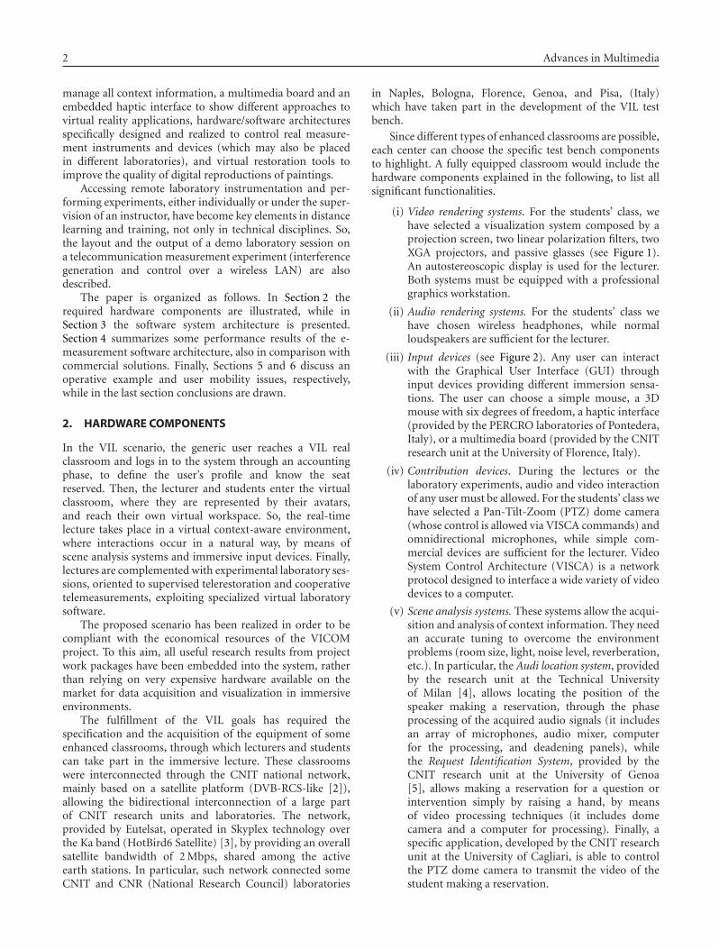
2. HARDWARE COMPONENTS
In the VIL scenario, the generic user reaches a VIL realclassroom and logs in to the system through an accountingphase, to define the user’s profile and know the seatreserved. Then, the lecturer and students enter the virtualclassroom, where they are represented by their avatars,and reach their own virtual workspace. So, the real-timelecture takes place in a virtual context-aware environment,where interactions occur in a natural way, by means ofscene analysis systems and immersive input devices. Finally,lectures are complemented with experimental laboratory ses-sions, oriented to supervised telerestoration and cooperativetelemeasurements, exploiting specialized virtual laboratorysoftware.
The proposed scenario has been realized in order to becompliant with the economical resources of the VICOMproject. To this aim, all useful research results from projectwork packages have been embedded into the system, ratherthan relying on very expensive hardware available on themarket for data acquisition and visualization in immersiveenvironments.
The fulfillment of the VIL goals has required thespecification and the acquisition of the equipment of someenhanced classrooms, through which lecturers and studentscan take part in the immersive lecture. These classroomswere interconnected through the CNIT national network,mainly based on a satellite platform (DVB-RCS-like [2]),allowing the bidirectional interconnection of a large partof CNIT research units and laboratories. The network,provided by Eutelsat, operated in Skyplex technology overthe Ka band (HotBird6 Satellite) [3], by providing an overallsatellite bandwidth of 2 Mbps, shared among the activeearth stations. In particular, such network connected someCNIT and CNR (National Research Council) laboratories
in Naples, Bologna, Florence, Genoa, and Pisa, (Italy)which have taken part in the development of the VIL testbench.
Since different types of enhanced classrooms are possible,each center can choose the specific test bench componentsto highlight. A fully equipped classroom would include thehardware components explained in the following, to list allsignificant functionalities.
(i) Video rendering systems. For the students’ class, wehave selected a visualization system composed by aprojection screen, two linear polarization filters, twoXGA projectors, and passive glasses (see Figure 1).An autostereoscopic display is used for the lecturer.Both systems must be equipped with a professionalgraphics workstation.
(ii) Audio rendering systems. For the students’ class wehave chosen wireless headphones, while normalloudspeakers are sufficient for the lecturer.
(iii) Input devices (see Figure 2). Any user can interactwith the Graphical User Interface (GUI) throughinput devices providing different immersion sensa-tions. The user can choose a simple mouse, a 3Dmouse with six degrees of freedom, a haptic interface(provided by the PERCRO laboratories of Pontedera,Italy), or a multimedia board (provided by the CNITresearch unit at the University of Florence, Italy).
(iv) Contribution devices. During the lectures or thelaboratory experiments, audio and video interactionof any user must be allowed. For the students’ class wehave selected a Pan-Tilt-Zoom (PTZ) dome camera(whose control is allowed via VISCA commands) andomnidirectional microphones, while simple com-mercial devices are sufficient for the lecturer. VideoSystem Control Architecture (VISCA) is a networkprotocol designed to interface a wide variety of videodevices to a computer.
(v) Scene analysis systems. These systems allow the acqui-sition and analysis of context information. They needan accurate tuning to overcome the environmentproblems (room size, light, noise level, reverberation,etc.). In particular, the Audi location system, providedby the research unit at the Technical Universityof Milan [4], allows locating the position of thespeaker making a reservation, through the phaseprocessing of the acquired audio signals (it includesan array of microphones, audio mixer, computerfor the processing, and deadening panels), whilethe Request Identification System, provided by theCNIT research unit at the University of Genoa[5], allows making a reservation for a question orintervention simply by raising a hand, by meansof video processing techniques (it includes domecamera and a computer for processing). Finally, aspecific application, developed by the CNIT researchunit at the University of Cagliari, is able to controlthe PTZ dome camera to transmit the video of thestudent making a reservation.

Luca Berruti et al. 3
3D visualization
Stereoscopic projection
Virtual object synthesis
Figure 1: Video rendering system for the students’ class.
Virtual environment
Multimedia board
Phantom haptic interface
Figure 2: Input devices.
3. SOFTWARE ARCHITECTURE
The software architecture is illustrated in Figure 3. Thecommon experience manager (CEM) is certainly the mainblock of such architecture, as it manages both e-learningand experimental laboratory sessions. Context is capturedand analyzed by the scene analysis (SA) module, througharrays of microphones and cameras. Such informationis stored in the VIL database and managed by a Javainterface.
Any student can select a synchronous or asynchronousinstruction course. In the former case, the CEM manages theinteraction between students and lecturer through a token-based mechanism: the lecturer is able to entirely release or toshare its privileges, communicating with the CEM throughan immersive Graphical User Interface (GUI). Interactiveinputs (II) allow interaction with the virtual environment,while contribution inputs (CI) permit to ask questions duringa lecture, after being enabled by the lecturer: interventionsoccur by video and audio streaming. In the latter case,a student can download a previous lecture stored in theLectures’ Repository by means of the video communicationsover IP (VIP)-teach recorder and visualize these offlinecontents by using a specific player.
Remoteclassroom 1
Remoteclassroom 2
Remoteclassroom N
VILdatabase
VILCEM
VIP-teachserver
3D serverLNS
VIP-teachrecorder
Lectures’repository
Remote laboratory / restoration environment
Instrument 2
Instrument 1
Instrument N
Instrumentationcluster manager
Remoteclassroom
SA
II
CI
LecturerGUI
StudentGUI
Unified GUI
Figure 3: Main blocks of the software architecture.
Finally, the LabNet server (LNS) and the instrumentationcluster manager (also named experience manager) providethe remote control of real laboratory instrumentation, aspresented in Section 3.2.
3.1. Graphical user interfaces
A new immersive GUI has been developed to support 3Dcontents in the synchronous e-learning application VIP-Teach, provided by LightComm (http://www.lightcomm.it).The components of this GUI (see Figure 4) are video(MPEG4 codec), chat, ppt presentations, 3D space, andmanagement window (with the list of students online andof those making a reservation). In particular, 3D contents inthe lecture session are realized in Virtual Reality ModelingLanguage (VRML) and controlled by Java applications toobtain highly interactive and immersive worlds, whosebehavior is modified by user actions [6] in real-time.3D Studio Max, VIZ and Maya, among others, can beused to generate and export nonelementary environmentsin VRML files format. They in fact allow navigation inthe 3D environment, management of collisions among 3Dobjects, visualization of the avatars of other users movingin the environment, visualization of reservation events andinformation about users, search of an avatar by name andselection of a laboratory session.
During the lecture, the lecturer can select a laboratorysession, simply by clicking on a virtual door present inthe scene. 3D contents in the laboratory sessions (see

4 Advances in Multimedia
Figure 4: GUI in the lecture session.
1. Tele-restoration
2. Tele-measurement
Many-to-one
3. Tele-measurement
One-to-many
Figure 5: GUI in the laboratory sessions.
Figure 5) are modeled through 3D Studio Max and con-trolled through eXtreme Virtual Reality (XVR) by VRMedia(http://www.vrmedia.it/).
The telerestoration session, realized by the CNIT researchunits at the Universities of Florence and Pisa S. Anna,allows experimenting virtual restoration techniques (suchas crack removal and lacuna filling) on high-resolutiondigital copies of famous paintings [7], while the twotelemeasurement sessions permit to interact with real instru-mentation. In the many-to-one paradigm, developed in theCNIT National Laboratory for Multimedia Communications(Naples) [8], the experience is collaborative, namely, theGUI interface allows the lecturer to transfer the experiment’scontrol to the students, while in the one-to-many paradigm,realized at the WiLab laboratories (Bologna) [9], it ispossible to interact with a “measurement chain,” whoseinstrumentation is geographically distributed in differentlocations.
As concerns telerestoration, the devised tool aims atobtaining a digital version of the artwork where all damageshave been removed; the great advantage is that if a mistakewas made, the artwork does not suffer any kind of injury, andthe virtual restorer can start again the restoration process.
This can be useful for educational aims, in order to look atthe artwork as it was in the intent of the artist who made it,and for guidance aims, in order to give the actual restorer thepossibility to perform some useful tests before choosing thebest restoration technique. The telerestoration session [10]permits to download high-quality digital images in bitmapformat, to zoom in the images, and to restore a crack anda lacuna according to the techniques actually used duringrestorations. Indeed, cracks and lacunas are two of the mainproblems a painting or a fresco can be affected by. Theydeteriorate the artworks more or less significantly dependingon their number and their severity.
The telerestoration session is able to remove cracks in asemiautomatic way, as it requires the aid of a human user,who has to select one of the pixels belonging to the crack; thereason for this is that only an observer can decide if a darkline is a crack or it belongs to the texture or the subject ofthe artwork. So suitably initialized, the restoration automaticprocedure is able to recover the whole crack by means of aninterpolation technique.
Lacunas occur when some parts of the artwork collapseand fall down, resulting in a lack of paint. The telerestorationsession operates by repainting the parts that have collapsedaccording to some restoration methods, such as chromaticselection, chromatic abstraction, rigatino, and pointellism.Their aim is to fill in the lacuna, so as to recover thecoarse uniformity of the artwork and avoid the presence ofannoying holes in the whole image.
As regards the telemeasurement system, the virtualinstruments in the many-to-one paradigm represent thelaboratory “active elements,” in the sense that knobs, but-tons, and displays present on their front panels can bedynamically controlled by the users or updated on thebasis of measurement results. These active elements arehandled by Java applets (running within the framework ofan XVR application), which communicate with the server-side infrastructure in order to exchange commands, data,and results to/from the real remote instrumentation.
XVR, by means of which all laboratory sessions havebeen represented, is an integrated environment for the rapiddevelopment of Virtual Reality applications. XVR is struc-tured in two main modules: the ActiveX control module,which hosts the very basic components of the technology(like the versioning check and the plugin interfaces), andthe XVR Virtual Machine (VM) module, which contains thecore of the technology (such as the 3D graphics engine, themultimedia engine, and all the software modules managingthe other built-in XVR features).
XVR features include: client plugin as an ActiveX controlfor Internet Explorer, import of models from 3DSMax 4.0or higher, advanced OpenGL rendering engine, dedicatedscript language (S3D), vertex and pixel shaders’ support,supplied byte-code compiler, run-time expandable modulecapabilities, HTML pages interaction using JavaScript orVBScript, video textures supporting AVI, import of FLASHimages as 3D textures. Supported audio formats includeWAV, MIDI, MP3, and WMA; other features are positional3D audio support, input devices’ management, remoteconnections support (TCP and UDP management).

Luca Berruti et al. 5
3.2. Server-side architecture
The main components of the CEM are the VIP-Teach server,the LabNet server, and the 3D server, as shown in Figure 6.
The VIP-Teach server is able to manage users’ accountsand permissions, enrol the students in the lectures, andactivate the PowerPoint viewer on the remote PCs. Itcan be followed by a web portal, for the management ofthe lectures’ calendar and for the offline diffusion of pptpresentations, and by a recorder that allows recording thelecture.
The LabNet server [8], an ad hoc supervising cen-tral unit (SCU), manages access to a generic experiment,guaranteeing interoperability and synchronization amongusers. Particularly, owing to a control module, it makes theexperience collaborative, allowing a super user (the lecturer)the possibility to pass the instrumentation control (token) tousers of inferior level (the students), through the VIP-Teachclient interface. Besides, owing to the data provision module,the instrument data are distributed to users in multicastfashion, and can be visualized on the 3D interface, via a Java-based adaptation layer.
The 3D manager (i.e., the main component of the3D server) is a pure Java application able to manage theVIL database and information related to the graphicalrepresentation, and to handle authorizations of avatars andthe logical structure of the scene.
At the transport layer, the VIP-Teach server adopts UDPfor audio/video streams and TCP for session management.TCP is also used by the 3D server. The LabNet server adoptsboth TCP and UDP, and their use will be specified in moredetail below.
The software architecture for e-measurement experi-ments, developed at the National Laboratory for MultimediaCommunications in Naples, is shortly explained in Figure 7,by using a top-down approach. The SW modules involved inthe architecture are explained in the following.
(i) The 3D GUI displays the instrument data andcommunicates with the rest of the architecture via aJava-based interface.
(ii) The LNS (LabNet server) manages the access of usersto the experiments and distributes the instrumentdata.
(iii) The experience manager manages the allocation ofthe instruments in the individual experiments, thecorrespondence among the experiment’s variablesand actions on the instrumentation drivers.
(iv) The experience database contains the experimenttable (to list the instruments involved in each one)and instrument table (to define the allocation state).
(v) Test beds are the set of instrumentation drivers for e-measurement sessions.
User data communication relies upon UDP, in unicastor multicast fashion. This connectionless communicationprotocol is light and efficient even on a satellite link, butalso unreliable. Therefore, the LNS has to deal with lost
VIP-teach client &VIL DB
VIP-teachclient
Java adaptationlayer
3D client &VIL DB
VIP-teachserver
LNScontrol
LNS dataprovision
Webserver
3Dmanager
Labnetserver
3Dserver
Figure 6: Main components of CEM.
3D GUI
Java adaptation layer
LNS data provision
Experience manager
Testbeds
Experiencedatabase
Figure 7: SW architecture for e-measurement session.
packets and quality of service (QoS) problems. Laboratorysessions often involve a large number of user stations, andso multicast transmission should be chosen (wherever it issupported by the network) for a more efficient use of theavailable bandwidth. On the other hand, for each kind ofuser, there is a reliable control connection to the server overthe TCP communication protocol. It is used both for tokenexchange and for starting or taking part in an experiment.TCP is heavier than UDP, but it guarantees stability andcontrol of parameters that are critical for the correct workingof the system.
The LNS knowledge is limited to the experimentsand to their allocation, based on different types of useraccess, but it does not concern the instruments beingused. The experience manager in fact establishes thelink between the LNS and the heterogeneous instrumen-tation world, managing the instruments’ allocation anddrivers’ actions. In particular, to call the driver proce-dures, the experience manager adopts remote procedurecalls (RPCs) through Simple Object Access Protocol (SOAP),using Extended Markup Language (XML) to encode its callsand HyperText Transfer Protocol (HTTP) as a transportmechanism [11]. The drivers recognize SOAP-RPC mes-sages and translate them into reading/writing commandson the instruments’ allocation involved in the experi-ment.
6 Advances in Multimedia
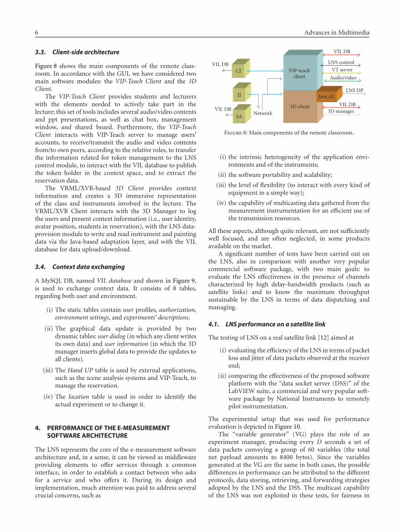
3.3. Client-side architecture
Figure 8 shows the main components of the remote class-room. In accordance with the GUI, we have considered twomain software modules: the VIP-Teach Client and the 3DClient.
The VIP-Teach Client provides students and lecturerswith the elements needed to actively take part in thelecture; this set of tools includes several audio/video contentsand ppt presentations, as well as chat box, managementwindow, and shared board. Furthermore, the VIP-TeachClient interacts with VIP-Teach server to manage users’accounts, to receive/transmit the audio and video contentsfrom/to own peers, according to the relative roles, to transferthe information related for token management to the LNScontrol module, to interact with the VIL database to publishthe token holder in the context space, and to extract thereservation data.
The VRML/XVR-based 3D Client provides contextinformation and creates a 3D immersive representationof the class and instruments involved in the lecture. TheVRML/XVR Client interacts with the 3D Manager to logthe users and present context information (i.e., user identity,avatar position, students in reservation), with the LNS data-provision module to write and read instrument and paintingdata via the Java-based adaptation layer, and with the VILdatabase for data upload/download.
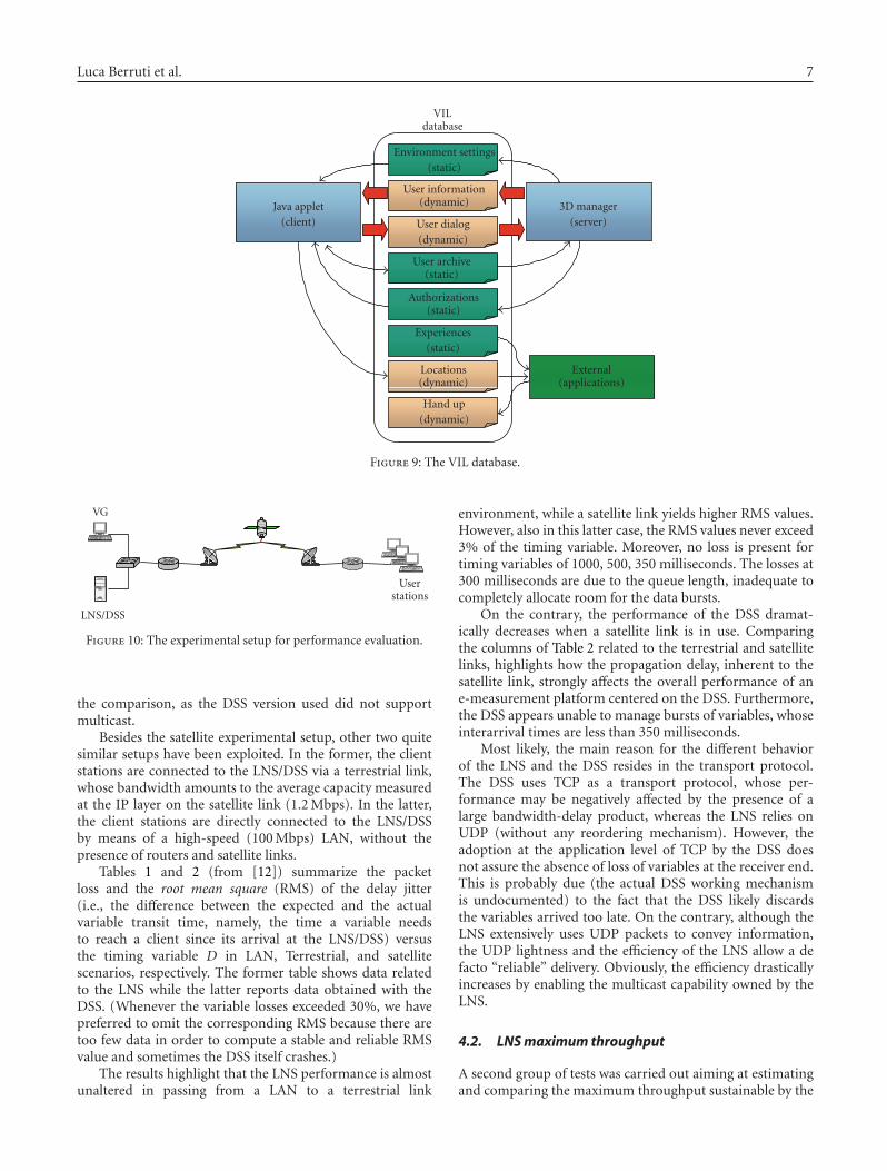
3.4. Context data exchanging
A MySQL DB, named VIL database and shown in Figure 9,is used to exchange context data. It consists of 8 tables,regarding both user and environment.
(i) The static tables contain user profiles, authorization,environment settings, and experiments’ descriptions.
(ii) The graphical data update is provided by twodynamic tables: user dialog (in which any client writesits own data) and user information (in which the 3Dmanager inserts global data to provide the updates toall clients).
(iii) The Hand UP table is used by external applications,such as the scene analysis systems and VIP-Teach, tomanage the reservation.
(iv) The location table is used in order to identify theactual experiment or to change it.
4. PERFORMANCE OF THE E-MEASUREMENTSOFTWARE ARCHITECTURE
The LNS represents the core of the e-measurement softwarearchitecture and, in a sense, it can be viewed as middlewareproviding elements to offer services through a commoninterface, in order to establish a contact between who asksfor a service and who offers it. During its design andimplementation, much attention was paid to address severalcrucial concerns, such as
VIL DB
VIL DBNetwork
CI
II
SA
VIP-teachclient
3D client
VIL DB
LNS control
VT server
Audio/video
LNS DPJava AL
VIL DB3D manager
Figure 8: Main components of the remote classroom.
(i) the intrinsic heterogeneity of the application envi-ronments and of the instruments;
(ii) the software portability and scalability;
(iii) the level of flexibility (to interact with every kind ofequipment in a simple way);
(iv) the capability of multicasting data gathered from themeasurement instrumentation for an efficient use ofthe transmission resources.
All these aspects, although quite relevant, are not sufficientlywell focused, and are often neglected, in some productsavailable on the market.
A significant number of tests have been carried out onthe LNS, also in comparison with another very popularcommercial software package, with two main goals: toevaluate the LNS effectiveness in the presence of channelscharacterized by high delay-bandwidth products (such assatellite links) and to know the maximum throughputsustainable by the LNS in terms of data dispatching andmanaging.
4.1. LNS performance on a satellite link
The testing of LNS on a real satellite link [12] aimed at
(i) evaluating the efficiency of the LNS in terms of packetloss and jitter of data packets observed at the receiverend;
(ii) comparing the effectiveness of the proposed softwareplatform with the “data socket server (DSS)” of theLabVIEW suite, a commercial and very popular soft-ware package by National Instruments to remotelypilot instrumentation.
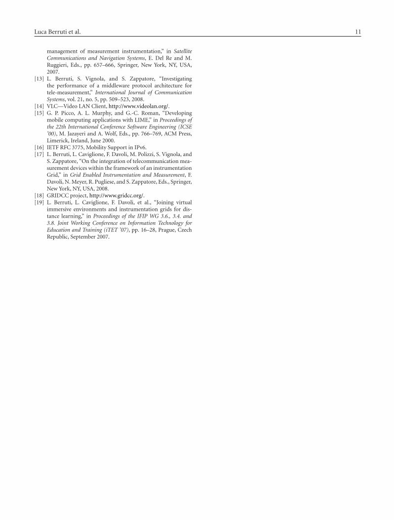
The experimental setup that was used for performanceevaluation is depicted in Figure 10.
The “variable generator” (VG) plays the role of anexperiment manager, producing every D seconds a set ofdata packets conveying a group of 60 variables (the totalnet payload amounts to 8400 bytes). Since the variablesgenerated at the VG are the same in both cases, the possibledifferences in performance can be attributed to the differentprotocols, data storing, retrieving, and forwarding strategiesadopted by the LNS and the DSS. The multicast capabilityof the LNS was not exploited in these tests, for fairness in
Luca Berruti et al. 7
VILdatabase
Environment settings(static)
User information(dynamic)
User dialog(dynamic)
User archive(static)
Authorizations(static)
Experiences(static)
Locations(dynamic)
Hand up(dynamic)
Java applet(client)
3D manager(server)
External(applications)
Figure 9: The VIL database.
VG
LNS/DSS
Userstations
Figure 10: The experimental setup for performance evaluation.
the comparison, as the DSS version used did not supportmulticast.
Besides the satellite experimental setup, other two quitesimilar setups have been exploited. In the former, the clientstations are connected to the LNS/DSS via a terrestrial link,whose bandwidth amounts to the average capacity measuredat the IP layer on the satellite link (1.2 Mbps). In the latter,the client stations are directly connected to the LNS/DSSby means of a high-speed (100 Mbps) LAN, without thepresence of routers and satellite links.
Tables 1 and 2 (from [12]) summarize the packetloss and the root mean square (RMS) of the delay jitter(i.e., the difference between the expected and the actualvariable transit time, namely, the time a variable needsto reach a client since its arrival at the LNS/DSS) versusthe timing variable D in LAN, Terrestrial, and satellitescenarios, respectively. The former table shows data relatedto the LNS while the latter reports data obtained with theDSS. (Whenever the variable losses exceeded 30%, we havepreferred to omit the corresponding RMS because there aretoo few data in order to compute a stable and reliable RMSvalue and sometimes the DSS itself crashes.)
The results highlight that the LNS performance is almostunaltered in passing from a LAN to a terrestrial link
environment, while a satellite link yields higher RMS values.However, also in this latter case, the RMS values never exceed3% of the timing variable. Moreover, no loss is present fortiming variables of 1000, 500, 350 milliseconds. The losses at300 milliseconds are due to the queue length, inadequate tocompletely allocate room for the data bursts.
On the contrary, the performance of the DSS dramat-ically decreases when a satellite link is in use. Comparingthe columns of Table 2 related to the terrestrial and satellitelinks, highlights how the propagation delay, inherent to thesatellite link, strongly affects the overall performance of ane-measurement platform centered on the DSS. Furthermore,the DSS appears unable to manage bursts of variables, whoseinterarrival times are less than 350 milliseconds.
Most likely, the main reason for the different behaviorof the LNS and the DSS resides in the transport protocol.The DSS uses TCP as a transport protocol, whose per-formance may be negatively affected by the presence of alarge bandwidth-delay product, whereas the LNS relies onUDP (without any reordering mechanism). However, theadoption at the application level of TCP by the DSS doesnot assure the absence of loss of variables at the receiver end.This is probably due (the actual DSS working mechanismis undocumented) to the fact that the DSS likely discardsthe variables arrived too late. On the contrary, although theLNS extensively uses UDP packets to convey information,the UDP lightness and the efficiency of the LNS allow a defacto “reliable” delivery. Obviously, the efficiency drasticallyincreases by enabling the multicast capability owned by theLNS.
4.2. LNS maximum throughput
A second group of tests was carried out aiming at estimatingand comparing the maximum throughput sustainable by the

8 Advances in Multimedia
Table 1: Performance results in the presence of the LNS.
Variable time D [ms]LAN Terrestrial Satellite
Loss [%] RMS [μs] Loss [%] RMS [μs] Loss [%] RMS [μs]
1000 0 70 ± 2 0 139 ± 71 0 16615 ± 70
500 0 72 ± 3 0 170 ± 78 0 15980 ± 240
350 0 75 ± 4 0 258 ± 90 0 11030 ± 530
300 0 71 ± 5 1.6 14141 ± 78 2.3 9120 ± 212
Table 2: Performance results in the presence of the DSS.
Variable time D [ms]LAN Terrestrial Satellite
Loss [%] RMS [μs] Loss [%] RMS [μs] Loss [%] RMS [μs]
1000 0 16750 0.2 103000 60 —
500 0 14500 25 189000 82 —
350 1.3 24500 60 — 96 —
Table 3: Variables’ loss at the user stations versus different loadsproduced at the VG.
Load produced LNS variables’ DSS variables’
at the VG loss loss
269 kbps 0% 0.2%
340 kbps 0% 9.5%
2100 kbps 0% 33%
15 Mbps 0% —
20 Mbps 5.24% —
25 Mbps 26.37% —
LNS and DSS, by measuring the value of variables’ loss atthe receiver ends in a simple LAN scenario with 4 clientstations. In each row, Table 3 [13] reports the variables’ lossobserved when the LNS and the DSS are in use, at a specificlevel of traffic load produced at the VG. Above 2100 kbps,the variable loss introduced by the DSS cannot be measured,as the DSS seems incapable to support such heavy loads;variables’ updates are no longer notified to the user stations,and sometimes the DSS itself crashes.
Again, the performance of the LNS appears to besignificantly better than that shown by the DSS; furthermore,especially as concerns the packet loss, the performance of theDSS dramatically decreases when heavy loads are producedby the VG.
5. AN OPERATIVE EXAMPLE
A specific remotely controlled demo has been set up inthe many-to-one telemeasurement session by the NationalLaboratory for Multimedia Communications in Naples. Itsgoal is to remotely test the operating conditions of a WLAN,in the presence of an adjacent interfering channel, producedby a vector signal generator.
In particular, the qualitative (and, to some extent,quantitative) analysis of the channel throughput is allowed,by observing the quality of a received video sequence and the
number of dropped packets and, at the same time, by viewingthe resulting waveform on the display of a virtual instrumentrepresenting a remotely controlled real spectrum analyzer.The video TX produces a Motion-JPEG encoded stream thatfeeds the access point (AP) on the right of Figure 11. TheRF output of this AP is combined with an interfering signalproduced by an Agilent E-4438C vector signal generator. Theresulting sum traverses a splitter, where the main part ofthe signal power is directed to the video receiver through asecond AP. The decoded video stream is retransmitted over asatellite WAN link or over the Internet (from the NationalLaboratory for Multimedia Communications in Naples toany remote site) toward the remote observer. Another part ofthe interfered signal reaches a spectrum analyzer (Agilent E-4404B), where the interference phenomenon can be remotelydisplayed. The GPIB bus (suitably bridged to the laboratoryLAN by the E-NET device) disseminates commands andgathers responses from the instruments, thus permittingtheir complete remote control.
In our experimental setup, the video TX is represented bya VLC application [14], which generates the signal under test(viz the MotionJPEG-encoded video), while the interferingtraffic consists of a deterministic constant bit rate signal,whose power can be selected by the remote user.
By using the 3D GUI (see Figure 12), it is possible toturn the virtual instrumentation on and off, by clicking onON/OFF buttons, to see the interfered signal characteristicson a device’s display (e.g., a spectrum analyzer), to observethe quality of a received video sequence, to pass and revokethe token to/from a student, to know the statistics of a videotransmission and to set the values of experiment variables, byclicking on the instrument’s buttons.
For example, when the two transmissions are onnonoverlapping channels (interfering traffic on CH 1 andvideo one on CH 7) any user can see a very fluent receivedvideo, practically no dropped packets, and the classicalspectrum of a WLAN transmission. If the interfering signalis shifted on an adjacent channel (CH 6), it is possible to seesome dropped packets and a low video quality. If the two

Luca Berruti et al. 9
GPIB bus
GPIB-enet
Video TX Cisco AP Combiner2.5 GHz
RF signal Power splitter2.5 GHz
Cisco AP
Labnet site
Ethernet
VIPserver
Experiencemanager
LNS 3D-MySQLserver
Eth
ern
et
8box
Skyplex
Labnet satellite antenna
Remote site
VICom client
8box
Skyplex
EthernetRemote satellite antenna
InterferingRF signal
Figure 11: Demo architecture in the many-to-one telemeasurement session.
Figure 12: GUI in the many-to-one telemeasurement session.
transmissions are on the same channel (CH 7), the videotransmission is completely stopped and it is possible to seea very disturbed spectrum. At this point, if the amplitude ofthe interfering signal is lowered, the video transmission canstart again.
6. USER MOBILITY ISSUES
The VIL test bed does not address mobility issues explicitly.As a matter of fact, the core of the distance learningapplication does not change, even in case the client usedto follow a lecture or access a laboratory session is char-acterized by a certain degree of mobility. Wireless access, a
requisite for mobility, has been indeed considered, since theconnection in the example experiment we have describedrelied upon a satellite link. In this respect, it is worthremembering that the LabNet server protocol, adopted forthe management of the client population in the accessand control of the measurement devices, has been shownto exhibit a very satisfactory degree of robustness whenused over high bandwidth-delay product networks (e.g.,satellite or even some types of wireless cellular networks),also in comparison to widespread commercial solutions.Moreover, the full functionalities of the system may beaccessed from a wireless network in general, provided thata transmission speed in the range 0.8–1 Mbps is achiev-able. Problems regarding security should be handled byappropriate authentication and data protection. PossibleQoS provisioning mechanisms may be adopted over thewireless link and at the wired/wireless network bound-aries.
As regards specifically user mobility, a link with themechanisms developed within the VICOM project (mobileimmersive environment (MIE) testbed) for localizationand user guidance may be established. Such mechanisms,based on the use of multiple localization techniques, wouldfacilitate the mobile users in reaching specially equippedclassrooms, where they can take advantage of advancedinterfaces (e.g., multimedia board, haptic interfaces, or 3Dvideo rendering).
Future developments will regard the establishment of asoftware interface between LINDA in a mobile environment(LIME) [15], the middleware used for handling the distri-bution of the context data in the MIE testbed, and the VIL

10 Advances in Multimedia
database, to automatically acquire profiles of mobile userswhen they enter the classroom.
A final observation regards the adoption of IPv6 atthe network layer, especially in conjunction with the needof facing user mobility issues. The VIL test bench hasbeen implemented over IPv4 networks, but it could easilymigrate to IPv6. In particular, the Mobile IPv6 (MIPv6)protocol, an IETF standard [16] to provide transparent hostmobility within IPv6, should be considered, as it presentsseveral differences to its IPv4 counterpart that providea simpler, more streamlined protocol (among others, noneed for foreign agents, route optimization as standard,integrated support—care of address (COA) and ingressfiltering, destination options, COA and multicast routing,use of IPv6 anycast for home agent discovery, etc.).
7. CONCLUSIONS
The paper has presented the design and implementation ofthe VIL test bed and its main related motivations, as wellas critical aspects. The software and hardware strategies,allowing reproduce the context of a real academic classroomin a virtual environment, have been described in some detail.
High portability, good flexibility, and, above all, lowcost, make this approach appropriate for educational andtraining purposes, mainly concerning measurements ontelecommunication systems, at universities and researchcenters, as well as enterprises.
Moreover, the methodology can be employed for remoteaccess to and sharing of costly measurement equipmentin many different fields of activity. In fact, the results ofa number of tests prove the effectiveness of the proposedsolution in terms of both high-sustainable throughput levelsand low-delay jitter in comparison with a very popular com-mercial software package, also in the presence of channelscharacterized by high delay-bandwidth products (such assatellite links).
As regards in particular the access and managementof remote measurement instrumentation and laboratoryequipment in general, it is worth mentioning that theLNS platform adopted in the VIL test bench is graduallyevolving toward a web services and Grid-based architecture[17], which exploits the functionalities initially developedin the framework of the GRIDCC European project [18].Specifically, the concept of instrument element (IE), devel-oped by GRIDCC, provides a set of services to control andmonitor remote physical devices; users view the IE as a setof web services, which provide a common language to thecross-domain collaboration and, at the same time, hide theinternal implementation details of accessing specific instru-ments. The integration of the VIL representation capabilitieswith Grid-based Remote Instrumentation Services has beenaddressed in [19].
ACKNOWLEDGMENTS
This work was funded by the Italian Ministry of Educationand Scientific Research (MIUR) in the framework of theFIRB VICOM project. The support of the previous LABNET
project in creating the e-measurement framework is alsogratefully acknowledged. This work is an extended versionof a paper presented at IMMERSCOM 2007, Bussolengo(Verona), Italy.
REFERENCES
[1] D. Tougaw and J. Will, “Visualizing the future of virtualreality,” Computing in Science & Engineering, vol. 5, no. 4, pp.8–11, 2003.
[2] Digital Video Broadcasting (DVB), “Interaction Channel forSatellite Distribution Systems,” ETSI EN 301 790, 2003.
[3] F. Davoli, G. Nicolai, L. S. Ronga, S. Vignola, S. Zappatore,and A. Zinicola, “A Ka/Ku band integrated satellite networkplatform for experimental measurements and services: theCNIT experience,” in Proceedings of the 11th Ka and BroadbandUtilization Conference, pp. 715–723, Rome, Italy, September2005.
[4] F. Antonacci, D. Lonoce, M. Motta, A. Sarti, and S. Tubaro,“Efficient source localization and tracking in reverberantenvironments using microphone arrays,” in Proceedings of theIEEE International Conference on Acoustics, Speech, and SignalProcessing (ICASSP ’05), vol. 4, pp. 1061–1064, Philadelphia,Pa, USA, March 2005.
[5] S. Piva, C. Bonamico, C. Regazzoni, and F. Lavagetto, “Aflexible architecture for ambient intelligence systems support-ing adaptive multimodal interaction with users,” in AmbientIntelligence, G. Riva, F. Vatalaro, F. Davide, and M. Alcaniz,Eds., pp. 97–120, IOS Press, Amsterdam, The Netherlands,2005.
[6] P. Pierleoni, T. Di Biase, G. Cancellieri, F. Fioretti, and S.Pasqualini, “The dynamic construction of multi-user VRML3D environment for immersive learning on the web,” inDistributed Cooperative Laboratories: Networking, Instrumen-tation, and Measurements, F. Davoli, S. Palazzo, and S.Zappatore, Eds., pp. 497–509, Springer, New York, NY, USA,2006.
[7] V. Cappellini, M. Barni, M. Corsini, A. De Rosa, and A.Piva, “ArtShop: an art-oriented image-processing tool forcultural heritage applications,” The Journal of Visualizationand Computer Animation, vol. 14, no. 3, pp. 149–158, 2003.
[8] F. Davoli, G. Spano, S. Vignola, and S. Zappatore, “LABNET:towards remote laboratories with unified access,” IEEE Trans-actions on Instrumentation and Measurement, vol. 55, no. 5, pp.1551–1558, 2006.
[9] O. Andrisano, A. Conti, D. Dardari, and A. Roversi, “Tele-measurement and circuit remote configuration through het-erogeneous networks: characterization of communicationssystems,” IEEE Transactions on Instrumentation and Measure-ment, vol. 55, no. 3, pp. 744–753, 2006.
[10] F. Bartolini, M. Barni, R. Caldelli, et al., “Research of theimage processing and communications lab. of the Universityof Florence in the cultural heritage field,” in Optical Metrologyfor Arts and Multimedia, vol. 5146 of Proceedings of SPIE, pp.116–126, Munich, Germany, June 2003.
[11] A. Vollono and A. Zinicola, “A new perspective in instrumen-tation interfaces as web services,” in Distributed CooperativeLaboratories: Networking, Instrumentation, and Measurements,F. Davoli, S. Palazzo, and S. Zappatore, Eds., pp. 451–461,Springer, New York, NY, USA, 2006.
[12] L. Berruti, F. Davoli, S. Vignola, and S. Zappatore, “Intercon-nection of laboratory equipment via satellite and space links:investigating the performance of software platforms for the
Luca Berruti et al. 11
management of measurement instrumentation,” in SatelliteCommunications and Navigation Systems, E. Del Re and M.Ruggieri, Eds., pp. 657–666, Springer, New York, NY, USA,2007.
[13] L. Berruti, S. Vignola, and S. Zappatore, “Investigatingthe performance of a middleware protocol architecture fortele-measurement,” International Journal of CommunicationSystems, vol. 21, no. 5, pp. 509–523, 2008.
[14] VLC—Video LAN Client, http://www.videolan.org/.[15] G. P. Picco, A. L. Murphy, and G.-C. Roman, “Developing
mobile computing applications with LIME,” in Proceedings ofthe 22th International Conference Software Engineering (ICSE’00), M. Jazayeri and A. Wolf, Eds., pp. 766–769, ACM Press,Limerick, Ireland, June 2000.
[16] IETF RFC 3775, Mobility Support in IPv6.[17] L. Berruti, L. Caviglione, F. Davoli, M. Polizzi, S. Vignola, and
S. Zappatore, “On the integration of telecommunication mea-surement devices within the framework of an instrumentationGrid,” in Grid Enabled Instrumentation and Measurement, F.Davoli, N. Meyer, R. Pugliese, and S. Zappatore, Eds., Springer,New York, NY, USA, 2008.
[18] GRIDCC project, http://www.gridcc.org/.[19] L. Berruti, L. Caviglione, F. Davoli, et al., “Joining virtual
immersive environments and instrumentation grids for dis-tance learning,” in Proceedings of the IFIP WG 3.6., 3.4. and3.8. Joint Working Conference on Information Technology forEducation and Training (iTET ’07), pp. 16–28, Prague, CzechRepublic, September 2007.

International Journal of
AerospaceEngineeringHindawi Publishing Corporationhttp://www.hindawi.com Volume 2010
RoboticsJournal of
Hindawi Publishing Corporationhttp://www.hindawi.com Volume 2014
Hindawi Publishing Corporationhttp://www.hindawi.com Volume 2014
Active and Passive Electronic Components
Control Scienceand Engineering
Journal of
Hindawi Publishing Corporationhttp://www.hindawi.com Volume 2014
International Journal of
RotatingMachinery
Hindawi Publishing Corporationhttp://www.hindawi.com Volume 2014
Hindawi Publishing Corporation http://www.hindawi.com
Journal ofEngineeringVolume 2014
Submit your manuscripts athttp://www.hindawi.com
VLSI Design
Hindawi Publishing Corporationhttp://www.hindawi.com Volume 2014
Hindawi Publishing Corporationhttp://www.hindawi.com Volume 2014
Shock and Vibration
Hindawi Publishing Corporationhttp://www.hindawi.com Volume 2014
Civil EngineeringAdvances in
Acoustics and VibrationAdvances in
Hindawi Publishing Corporationhttp://www.hindawi.com Volume 2014
Hindawi Publishing Corporationhttp://www.hindawi.com Volume 2014
Electrical and Computer Engineering
Journal of
Advances inOptoElectronics
Hindawi Publishing Corporation http://www.hindawi.com
Volume 2014
The Scientific World JournalHindawi Publishing Corporation http://www.hindawi.com Volume 2014
SensorsJournal of
Hindawi Publishing Corporationhttp://www.hindawi.com Volume 2014
Modelling & Simulation in EngineeringHindawi Publishing Corporation http://www.hindawi.com Volume 2014
Hindawi Publishing Corporationhttp://www.hindawi.com Volume 2014
Chemical EngineeringInternational Journal of Antennas and
Propagation
International Journal of
Hindawi Publishing Corporationhttp://www.hindawi.com Volume 2014
Hindawi Publishing Corporationhttp://www.hindawi.com Volume 2014
Navigation and Observation
International Journal of
Hindawi Publishing Corporationhttp://www.hindawi.com Volume 2014
DistributedSensor Networks
International Journal of