Embed Size (px)
Citation preview

@
Bell Bellcore PracticeCommunicationsResearch
BR 007-560-257Issue 2, August 1986
REMOTE CONSOLE UNIT (RCU) FOR
“PDP*” 11/40 MINICOMPUTERMETHOD OF OPERATIONINFORMATION SYSTEMS
PROPRIETARY—BELLCORE AND AUTHORIZED CLIENTS ONLYThis document contains proprietav information that shall be distributed or routed only within
Bell Communications Research (Bellcore) and Its authorized clients, except with written permission of Bellcora.

---
BR 007-560-257
Issue 2, August 1986
Prepared by the Information Management Services Division,Bell Communications Research, Inc., August 1986.
Copyright 01986 Bell Communications Research, Inc.All rights reserved.
PROPRIETARY – 13EIJXOREAND AUTHORIZEDCLIENTS ONLYSee proprietary restrictionson title page.

BR 007-560-257Issue 2, August 1986
1.
2.
3.
4.
5.
INTRODUCTION
1.01 Purpose .
. . . .
. . . .
1.02 Reason for Reissue . .
GENERAL . . . . . .
2.01 Baud Rate Switches .
2.02 Modem Option Switched
2.03 LED/Key Switches . .
DESCRIPTION OF TERMS
METHOD OF OPERATION
.
.
.
.
.
.
.
.
.
.
.
.
.
.
.
.
.
.
.
.
.
.
.
.
.
.
.
.
.
.
.
.
.
.
.
.
4.01
4.02
4.03
4.04
4.05
4.06
4.07
4.08
Establishing Contact With The RCU
Password . . . . . . . . .
Minicomputer Identification Option
Local Controls and Indicators . .
Command Entry Syntax . . . .
Remote and Local Access Commands
Miscellaneous Commands . . . .
Switch Status Notes . . . . .
SECURITY PROVISIONS . . . . .
LIST OF FIGURES
Figure 1. RCU CP-3 Layout . . . . . ,
LIST OF TABLES
TABLE A . . . . . . . . . . . .
TABLE B . . . . . . . . . . . .
TABLE C . . . . . . . . . . . .
.
.
.
.
.
.
.
.
.
.
.
.
.
.
.
.
.
.
.
.
.
.
.
.
.
.
.
.
.
.
.
.
.
.
.
.
.
.
.
.
.
.
.
.
.
.
.
.
.
.
.
.
.
.
.
.
.
.
.
.
.
.
.
.
.
.
.
.
.
.
.
.
.
.
.
.
.
.
.
.
.
.
.
.
.
.
.
.
.
.
.
.
.
.
.
.
.
.
.
.
.
.
.
.
.
.
.
.
.
.
.
.
.
.
.
.
.
.
.
.
.
.
.
.
.
.
.
.
.
.
.
.
.
.
.
.
.
.
.
.
.
.
.
.
.
.
.
.
.
.
.
.
.
.
.
.
.
.
.
.
.
.
.
.
.
.
.
.
.
.
.
.
.
.
.
.
.
.
.
.
.
.
.
.
.
.
.
.
.
.
.
.
.
.
.
.
.
.
.
.
.
.
.
.
.
.
.
.
.
.
.
.
.
.
.
.
.
.
.
.
.
.
.
.
.
.
.
.
.
.
.
.
.
.
.
.
.
.
.
.
.
.
.
.
.
.
.
.
.
.
.
.
.
.
.
.
.
.
.
.
.
.
.
.
.
.
.
.
.
.
.
.
.
.
.
.
.
.
.
.
.
.
.
.
.
.
.
.
.
.
.
.
.
.
.
.
.
.
.
.
.
.
.
.
.
.
.
.
.
.
.
.
.
.
.
.
.
.
.
.
.
.
.
.
1
1
1
1
1
1
1
~
3
3
3
4
5
6
8
10
11
11
. . . . . . . . . . . . . . . . . 2
. . . . . . . . . . . . . . . . . . 13
. . . . . . . . . . . . . . . . . . 13
. . . . . . . . . . . . . . . . . . 13
PROPRIETARY - BELLCOREAND AUTHORIZEDCLIENTS ONLYSee proprietary restrictionson title page.

I
BR 007-560-257Issue 2, August 1986
1. INTRODUCTION
1.01 Purpose
This practice contains the standard method of operation of the Remote Console Unit (RCU) for theDigital Equipment Corporation PDP 11/40 minicomputers. For a quick reference, refer to User’sManual (BR 007-560-259).
1.02 Reason for Reissue
This section is reissued due to divestiture.
2. GENERAL
The RCU is a microprocessor-based interface to PDP 11/40 minicomputers that permits remote diagnos-tic and monitor capability. The RCU was primarily designed as a maintenance tool for the telephonecompany Minicomputer Maintenance and Operations Center (MMOCS) and also as an operations toolfor software development organizations. Maintenance and operations personnel communicate with theRCU via a dial-up line using a data set and a standard receive/transmit American Standard Code forInformation Interchange (ASCII) terminal. Complete PDP 11/40 system console and terminal emulationis achieved.
An RCU kit consists of a circuit pack (CP-3) FE81NEO025, power supply and mounting hardware, com-munications cable (EIA/DC LOW/TTY), power cables, Light Emitting Diode (LED)/Key switchbracket, and miscellaneous hardware.
2.01 Baud Rate Switches
The two baud rate switches SW-4 and SW-5 located on the RCU CP-3 correspond to the speed optionsfor the remote and local terminals, respectively. The SW-4 and SW-5 are two lo-position thumbwheelswitches located in the middle upper half of the CP-3. (See Figure 1). Table A lists the switch positionsand their respective speeda.
CAUTION
The remote terminal speed must be greaterthan or equal to the local terminal speed. TheSW-4 switch should never be set to a baud ratelower than SW-5.
2.o2 Modem Option Switched
The modem option switches SW-2 and SW-3 are two quad Single-Pole Double Throw (SPDT) dipswitches located directly to the right of SW-4 and SW-5. (Refer to BR 007-560-258 for recommendedswitch positions and various optional operating parameters.)
2.03 LED/Key Switches
The LED/Key switch bracket contains three LED indicators, a Local/Remote mode control key switch,and a DISCONNECT CARRIER button connector. The LEDs consist of (from top to bottom) a
REMOTE LED, a CARRIER DETECT LED, and an RCU ACTIVE LED (operates at approximately 60beats per minute). See CP-3 layout (Figure 1) for bracket location. The Local/Remote mode control
key switch (Chicago Lock Company, No. 4235, using a keyed-alike design to that of the console keyswitch used on the PDP 11/40) is located below the LEDs. (Refer to Figure 1). Its function is to allowthe local personnel control of RCU Local/Remote mode capabilities. (Refer to paragraph 4.04). The
PROPRllXAKY – BELLCOREANDAUTHORIZED CLIENTSONLYSee proprietary restrictionson title page.

—.
BR 007-56f&257Issue 2, August 1986
DISCONNECT CARRIER button located between the LEDs and the key switch on the RCU front panelallows the local personnel to drop the remote user from the line automatically.
3. DESCRIPTION OF TERMS
The following list describes terms associated with the RCU PDP 11/40.
(a)
(b)
(c)
(d)
(e)
(f)
(g)
Remote Terminal: The standard receive/ transmit ASCII terminal located anywhere witha dial-up line and data set (or acoustic coupler).
Local Terminal: The minicomputer “system console.” It is the standard ASCII terminal(usually a DECWRITER* terminal) used by the associated minicomputer.
Switch Register: The bank of switches designated SWR17-SWROO located on the minicom-puter front console.
Remote Mode: The operating state of the RCU when the Local/Remote mode control keyswitch is in REMOTE.
Local Mode: The operating state of the RCU when the Local/Remote mode control keyswitch is in LOCAL.
Lockkg Switch: The switch located on the minicomputer front console that can be lockedin two positions is the HALT/ENABLE switch.
Momentary Switches: The switches located on the minicomputer front console that can bemomentarily switched to one additional position. They are- the CONT, LOAD, START,EXAM, and DEP switches.
Figure 1. RCU CP-3 Layout
● Trademark of Digital Equipment Corporation.
-WI
PROPRIHARY - BELWORE AND AUTHORIZED CLIENTS ONLYSee proprietary restrictionson title page.
2

BR 007-560-257Issue 2, August 1986
4. METHOD OF OPERATION
4.01 Establishing Contact With The RCU
The remote user contacts the RCU via the telephone network using the telephone number preassigned tothe RCU. The RCU supports full duplex ASCII terminals.
The data set connected to the RCU and also the data set (or acoustic coupler) connected to the remoteterminal must have the following features: binary, full duplex, asynchronous, a standard RS23?C inter-face, and be capable of operating within the RCU speed guidelines. (See paragraph 2.01 and Table A.)Several data set types and their significant operating parameters for interface to the RCU are listed inTable B.
The RCU ignores bit parity from the remote terminal during RCU command entry. The RCU remainstransparent to character structure during direct communication between the remote terminal and theminicomputer and the local terminal and the minicomputer.
4.02 Password
The RCU is equipped with a special access code fore security purposes. When a connection has beenestablished, the system types login. The user must then type the password followed by the RETURNkey. If the password was erroneously entered, the RCU will type login incorrect and again prompt theuser with another login.
The RCU system has a l-minute login time-out period at which time, if the remote user has not success-fully logged in, the RCU will drop the calling party. The RCU accomplishes this by holding the-DataTerminal Ready (DTR) lead from its connecting data set to a low logic level for approximately 10seconds. The caller can also be dropped by a local person (e.g., at the RCU front panel below the
actual minicomputer switch console) pressing the DISCONNECT CARRIER button. This can be doneat any point during the remote user’s contact with the RCU.
For security reasons, the RCU is not provided with a login password at the manufacturing location.The password must be programmed by the installation personnel during installation of the RCU. (Referto BR 007-560-258.) The password is physically located on a 2000- by 8-bit Ultraviolet Erasable Pro-grammable Read-Only Memory (UVEPROM) integrated circuit (IC39) (similar to the INTEL Company,
No. 2716. The IC39 is a Dual In-Line Package (DIP) located in a zer~insertion socket on CP-3 (Figure1). The password is local user changeable. The device (IC39) has the password loaded in memory loca-tions (addresses) 000H through 3ffH. (An “H” following a number signifies that the number is hexade-cimal.) The password characters must conform to the ASCII format. [DEL(7fH), @(40H), DC3( 13H),CR(OdH), and LF(OaH) are all exceptions in the ASCII format and should not be used in the password.]The parity bit, or the most significant bit, must be left as zero. There should be no hexadecimal char-
acter code greater than 7eH entered. The reason is that the RCU will only accept 7-bit ASCII from theremote terminal during login entries. The password may be up to 1000 characters but not less than 6,with an additional last character entered being a 00H. A recommended practice is to keep the charac-ter count within a reasonable range to allow time to type in characters before the login period time out.(Refer to Appendix 1 for step-by-step procedures to change password.)
CAUTION
The last character entered of the passwordmust be 00H. The password entered must be aminimum of 6 characters, difficult to guess, andunique to the RCU- installed processor, eg,
PROPRIETARY - BELLCOREA.NDAUTHORIZEDCLIENTS ONLYSee proprietary restrictionson title page.
—.
BR 007-56(L257Issue 2, August 1986
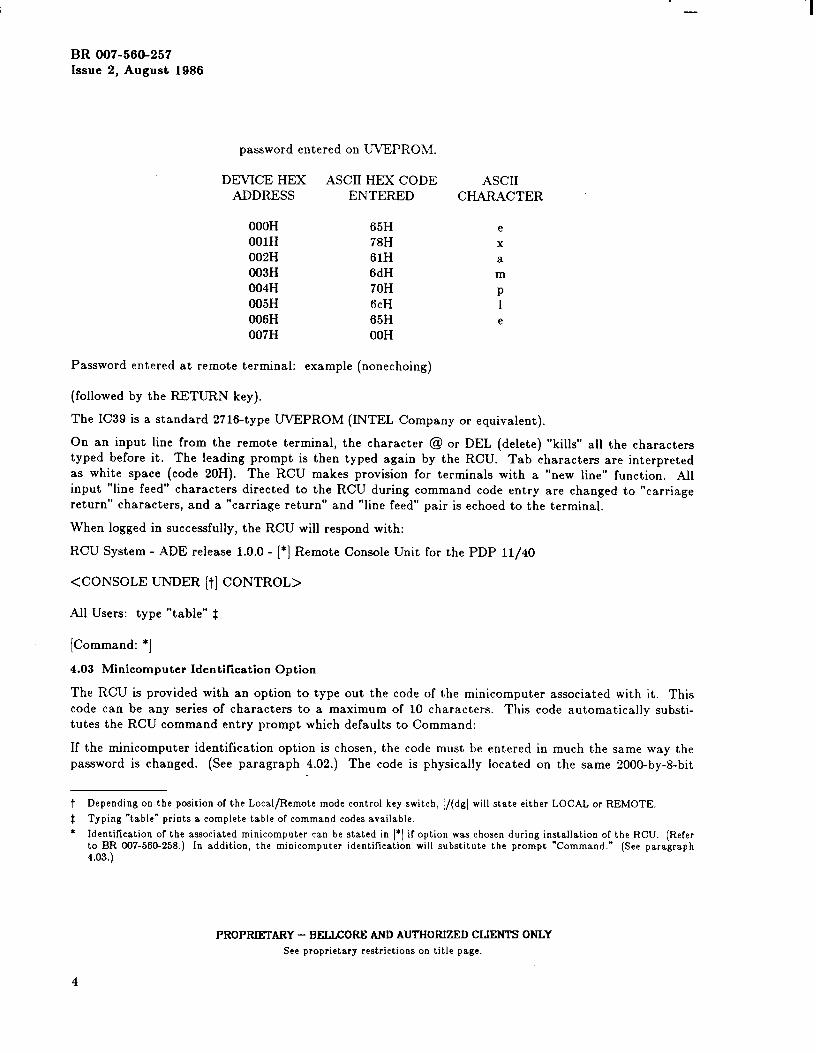
password entered on UVEPROM.
DEVICE HEX ASCII HEX CODE ASCIIADDRESS ENTERED CHARACTER
OOOHOOIHO02HO03HO04H005H006H007H
Password entered at remote terminal:
65H78H61H6dH70H6CH65H00H
example (nonechoing)
(followed by the RETURN key).
The IC39 is a standard 2716-type UVEPROM (INTEL Company
ex
am
P1e
or equivalent).
On an input line from the remote terminal, the character @ or DEL (delete) “kills” all the characterstyped before it. The leading prompt is then typed again by the RCU. Tab characters are interpretedas white space (code 20H). The RCU makes provision for terminals with a “new line” function. Allinput “line feed’* characters directed to the RCU during command code entry are changed to “carriagereturn” characters, and a “carriage return” and “line feed” pair is echoed to the terminal.
When logged in successfully, the RCU will respond with:
RCU System - ADE release 1.0.0- [*] Remote Console Unit for the PDP 11/40
<CONSOLE UNDER [t] CONTROL>
All Users: type “table” $
[Command: *]
4.o3 Minicomputer Identification Option
The RCU is provided with an option to type out the code of the minicomputer associated with it. Thiscode can be any series of characters to a maximum of 10 characters. This code automatically substi-tutes the RCU command entry prompt which defaults to Command:
If the minicomputer identification option is chosen, the code must be entered in much the same way thepassword is changed. (See paragraph 4.02.) The code is physically located on the same 2000-by-8-bit
t Dependingon the position of the Local/Remote mode control key switch, [/(dgl will state either LOCAL or REMOTE.
$ Typing “table” prints a complete table of command codes available.
* Identification of the associated minicomputer can be stated in [“] if option was chosen during installation of the RCU. (Referto BR 007-56& 258.) In addition, the minicomputer identification will substitute the prompt “Command.” (See paragraph4.03.)
PROPRIETARY – BELLCOREAND AUTHORIZEDCLIENTS ONLYSee proprietary restrictionson title page.
4
BR 007-560-257Issue 2, August 1986
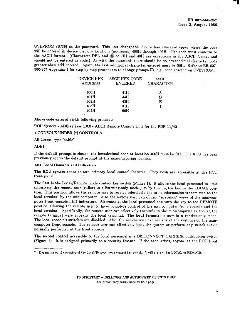
UVEPROM (IC39) as the password. This user changeable device has allocated space where the codewill be entered in device memory locations (addresses) 400H through 409H. The code must conform tothe ASCLI format. (Characters DEL and @ or 7fH and 40H are exceptions in the ASCII format andshould not be entered as code. ) As with the password, there should be no hexadecimal character codegreater then 7eH entered. Again, the last additional character entered must be OOH. Refer to BR 007-560-257 Appendix 1 for step-by-step procedures to change prompt-ill, e.g., code entered on UVEPROM:
DEVICE HEX ASCII HEX CODE ASCIIADDRESS ENTERED CHARACTER
400H 41H A401H 44H D402H 45H E403H 31H 1405H 00H
Above code entered yields following printout:
RCU System - ADE release 1.0.0- ADE1 Remote Console Unit for the PDP 11/40
<CONSOLE UNDER [*] CONTROL>
Ail Users: type “table”
ADE1:
If the default prompt is chosen, the hexadecimal code at location 400H must be ffH. The RCU has beenpreviously set to the default prompt at the manufacturing location.
4.o4 Local Controls and Indicators
The RCU system contains two primary local control features. They both are accessible at the RCUfront panel.
The first is the Local/Remote mode control key switch (Figure 1). It allows the local personnel to limitselectively the remote user (caller) to a listening-only mode just by turning the key to the LOCAL posi-
tion. This position allows the remote user to receive selectively the same information transmitted to thelocal terminal by the minicomputer. Also the remote user can obtain “snapshot” views of the minicom-puter front console LED indicators. Alternately, the local personnel can turn the key to the REMOTEposition allowing the remote user to have complete control of the minicomputer front console and thelocal terminal. Specifically, the remote user can selectively transmit to the minicomputer as though theremote terminal were actually the local terminal. The local terminal is now in a receive-only mode.The local console’s switches are disabled. Also, the remote user can set any of the switches on the mini-
computer front console. The remote user can effectively boot the system or perform any switch actionnormally performed at the front console.
The second control accessible to the local personnel is a DISCONNECT CARRIER pushbutton switch(Figure 1). It is designed primarily as a security feature. If the need arises, anyone at the RCLT front
* Depending on the position of the Local/Remote mode control key switch, [*] will state either LOCAL or REMOTE.
PROPRII!XARY – BELLCOREAND AUTHORIZEDCLIENTS ONLYSee proprietary restrictions on title page..

---
BR 007-560-257Issue 2, August 1986
panel may drop a remote user from the line simply by pressing a button. (Refer to Part 5, Security Pro-visions.)
The RCU system contains three visual indicators which are visible through the bezel window on theRCU front panel (Figure 1). These three LEDs are situated in a vertical pattern. They are red.
The top LED is the REMOTE mode LED. The OFF state is the Local mode condition and the ONstate is the Remote mode condition. The LED is a hard-wired connection to the Local/ Remote modecontrol key switch.
The lower LED is the RCU ACTIVE LED. It provides a visual “heartbeat” of the RCU system. TheRCU microprocessor (the BELLMAC*-8 microprocessor) toggles a flip-flop based circuit 60 times a
minute. The toggling LED driven from this circuit serves as an indicator of sanity of the microproces-sor.
The middle LED is the CARRIER DETECT LED. It provides visual confirmation that a remote user isin contact with the RCU. The ON state indicates that a caller is on the line and conversely the OFFstate indicates that the line is not seized. This LED is a hard-wired connection to the Carrier Detect(CD) lead from the connecting data set.
4.o5 Command Entry Syntax
After successfully logging in, the remote user receives a command prompt (default prompt is “Com-mand”) after which he/she may enter commands at will.
On an input line from a terminal, the character @ or DEL (delete) “kills” all the characters typedbefore it. The leading prompt is then typed again by the RCU. The character # or BS (backspace)erases the last character typed. Successive uses of # or BS will erase characters back to, but notbeyond, the beginning of the line. Tab characters are interpreted as white space (code 20H). The RCUmakes provision for terminals with a “new line” function. All input “line feed” characters directed tothe RCU are changed to “carriage return” characters, and a “carriage return” and “line feed” pair isechoed to the terminal.
The ASCII DC3 control character can be used to temporarily stop output. It is useful with a cathode-ray tube (CRT) terminal to prevent output from disappearing before it can be read. Output is resumedwhen any character is typed,
The RCU ignores bit parity from the remote terminal when any character is typed.
The RCU ignores bit parity from the remote terminal during RCU command entry.
The RCU will accept any unambiguous abbreviations of the commands.
The following control switch commands can be used to examine or change the generic portion of theprocessor’s memory. When the “dep,” “cent,” “exam,” or “load adrs” commands are implemented, theRCU will automatically continue by doing the “lights” command (paragraph 4.o1 ). The following com-
mands can only be accessed while in the Remote mode.
* Trademark of Western Electric Company.
PROPRIEXAIW – BELLCOREAND AUTHORIZEDCLIENTS ONLYSee proprietary restrictionson title page.
6

=
BR 007-560-257Issue 2, August 1986
Command
start
dep
Cent
exam
Function
Allows the remote user to activate the START switch. TheRCU will type to the remote user:
*START switch depressed
If the minicomputer CPU is in the RUN state, the STARTswitch has no effect. If the program has stopped, activating theSTART switch causes a System Reset signal to occur; the pr-gram will then continue only if the HALT/ ENABLE switch isin ENABLE. When the Remote HALT/ENABLE switch posi-tion is set to HALT, activating the START switch clears thecomputer system. The RCU will then type to the remote user:
<INIT>
When the Remote switch is set to ENABLE, activating theSTART switch automatically transfers the remote terminal intothe listening mode. (Refer to paragraph 4.06 for further infor-mation regarding listening mode.)
Allows the remote user to activate the DEP switch. Causes thecurrent contents of the switch register to be deposited into theaddress specified by the current contents of the address display.The RCU will type to the remote user:
*DEPOSIT switch activated
Allows the remote user to activate the CONT switch. Causesthe minicomputer processor to continue operation from thepoint at which it stopped. This switch has no effect when the
minicomputer processor is in the RUN state. If the programstops, this switch provides a restart without a system reset.The RCU will type to the remote user:
*CONTINUE switch depressed
Allows the remote user to activate the EXAM switch. Causesthe contents of the current location specified in the addressdisplay to be displayed in the Data Display Register when theData Select switch is in the DATA PATHS position. The RCUwill type to the remote user:
*EXAM switch depressed
PROPRIETARY - BEI.JXORE AlIll AUTHORIZE CLIENTSONIYSee proprietary restrictionson title page.
7

---
BR 007-560-257Issue 2, August 1986
Command
load adrs
halt or enable
Function
Allows the remote user to activate the LOAD ADRS switch.Transfers the contents of the switch register into the addressdisplayed. The RCU will type to the remote user:
*LOAD ADDRESS switch depressed
Allows the remote user to activate the HALT/ENABLE switch.
HALT:Causes the minicomputer processor to stop. The RCU willquery the remote user by typing to the remote user:
Are you sure? (y or n):
If the remote users types “Y” (upper or lower case), the RCU---will activate the HALT sw-itch. The RCU will then type theremote user:
*HALT switch depressed
If any character besidescommand.
“y” is typed, the RCU will ignore the
ENABLE:Allows the minicomputer processor to perform normal opera-tions underuser:
program control. The RCU will type to the remote
*ENABLE switch activated
4.o6 Remote and Local Access Commands
The command swr ~ allows the remote user to set the Remote Switch Register. The command “swr” fol-lowed by [ ] (zero to a maximum of six octal digits entered at the remote terminal) sets the RemoteSwitch Register equal to []. The digits entered [] are right justified and the remaining leftmost digitsdefault to zero. The RCU will type to the remote user:
REMOTE SWR = U
e.g., “swr77” yields: (RCU printout)
REMOTE SWR = 000077
While the Remote Switch Register can be set in Local or Remote modes, it is the effective ConsoleSwitch Register only in Remote mode. The Local Console Switch Register is disabled while the RCU is
in the Remote mode.
PROPRIETARY – BELIKORE AND AUTHORIZEDCLIENTS ONLYSee proprietary restrictionson title page.

i,,
–I
BR 007-560-257Issue 2, August 1986
The command “listening” allows the terminal of the remote user to be in direct communication with theminicomputer. The RCU transmits characters from the remote terminal to the minicomputer withoutchanging character format. Table C best illustrates the various communication modes and conditions ofthe remote terminal while in the listening mode.
The following procedures must be entered by the remote user in the specified order.
(1) To exit the listening mode:
● Start a new line.
● Press “Yo” key.
● Press control-g.
(2) To temporarily exit the listening mode (i.e., to execute an RCU command):
● Start a new line.
● Press “Yo” key.
. Enter RCU command.
● Press carriage return. *
(3) To transmit a % to the minicomputer as the first character on a new line, precede this charac-ter with another Yo.
CAUTION
Upon entering a % on a new line, the remoteterminal receive capability terminates. Theinformation transmitted to the local terminalby the minicomputer will not be received by theremote terminal. It will be reestablishedautomatically when returning from an RCUcommand [as in (2) above] or when enteringanother 70 [as in (3) above].
When in the listening mode, if the remote user attempts to prompt the minicomputer (e.g, starta new line) while in Local mode, the RCU will return the message:
<CONSOLE UNDER LOCAL CONTROL> - remote terminal can receive only.
The command “switches” informs the remote user of the most updated Local and Remote modeswitch settings. The RCU will print out who has control of the console functions. The RCU willprint out locking and rotary switch status of both LOCAL and REMOTE settings. The RemoteSwitch Register settings are also displayed. The format is displayed below:
<CONSOLE UNDER [“] CONTROL>
● The RCU will prompt the user with another % when the preset RCU command ends
PROPRIETARY - BELLCOREAND AUTHORIZEDCLIENTS ONLYSee proprietary restrictionson title page.
9
—.
BR 007-560-257Issue 2, August 1986
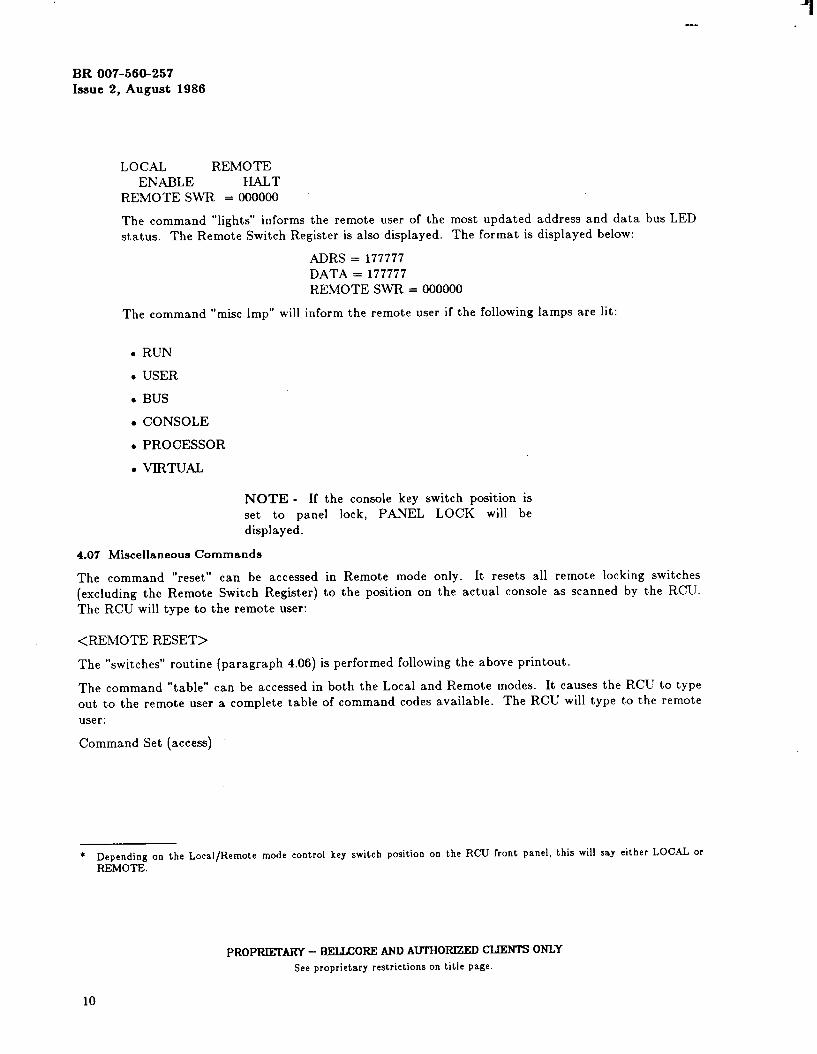
LOCAL REMOTEENABLE HALT
REMOTE SWR = 000000
The command “lights” informs the remote user of the most updated address and data bus LEDstatus. The Remote Switch Register is also displayed. The format is displayed below:
ADRS = 177777DATA = 177777REMOTE SWR = 000000
The command “mist imp” will inform the remote user if the following lamps are lit:
. RUN
● USER
● BUS
c CONSOLE
c PROCESSOR
● VIRTUAL
NOTE - If the console key switch position isset to panel lock, PANEL LOCK will bedisplayed.
4.o7 Mkcellaneous Commands
The command “reset” can be accessed in Remote mode only. It resets all remote locking switches
(excluding the Remote Switch Register) to the position on the actual console as scanned by the RCU.The RCU will type to the remote user:
<REMOTE RESET>
The “switches” routine (paragraph 4.06) is performed following the above printout.
The command “table” can be accessed in both the Local and Remote modes. It causes the RCU to typeout to the remote user a complete table of command codes available. The RCU will type to the remote
user:
Command Set (access)
* Depending on the Local/Remote mode control key switch position onREMOTE.
the RCU front panel, this will say either LOCAL or
PROPRD!XARY – BELLCOREAND AUTHORIZEDCLIENTS 0NL%See proprietary restrictionson title page.
10

—
BR 007-560-257Issue 2, August 1986
(Remote Only)startdepcentexamload adrshalt - enablereset
(Remote and Local)swrtablelightslisteningmist lmpswitches
The command “ .“ repeats the previously entered command. It will operate in both Local and Remotemodes except when present conditions (e.g., Local/Remote mode control key switch in LOCAL position)restrict previous commands (commands entered in the Remote mode) to be repeated.
4.08 Switch Status Notes
When a command that is only permitted to be entered in the Remote mode is entered in the Localmode, the RCU will type to the remote user:
? . <CONSOLE UNDER Loc~ CONTROL>
If the Local/Remote mode control key switch is set to REMOTE, the remote switch settings will remainas the remote user has left them regardless of the transition of carrier presence.
When switching the Local/Remote mode control key switch from the Remote to Local, the remoteswitch settings (except the Remote Switch Register) are automatically reset to whatever state the RCUscanned on the actual console.
5. SECURITY PROVISIONS
The following are security precautions:
(a) Required implementation features for password:
(1) The password must have a character length minimum equal to six.
(2) The password must be unique to the system.
(3) The password should not be guessed easily.
(b) Locai/Remote mode control key switch position:
(1) Do not leave the Local/Remote mode control key switch in the REMOTE positionunless required by authorized maintenance and/or operations personnel.
(2) Leave the Local/Remote mode control key switch in the LOCAL position at all timesexcept when required.
PROPRIETARY - BELLCOREAND AUTHORIZEDCLIENTS ONLYSee proprietary restrictionson title page.
11
-.
BR 007-560-257hue 2, August 1986
(c) Data set configuration:
(1) The telephone number associated with the data set should be unpublished.
(2) The data set should be set to a make-busy state when the RCU is not in use by author-ized personnel.
The following are security enhancements:
(a) An Led located on the RCU front panel lights when the Local/Remote mode control key switchis in the REMOTE position. This LED is designated REMOTE.
(b) Another LED located on the RCU front panel lights when anyone is in direct communicationwith the RCU. This LED is designated CARRIER DETECT.
(c) A pushbutton switch located on the RCU front panel (below the LEDs) drops any caller who isin direct communications with the RCU. This switch is designated DISCONNECT CARRIER.
If the security of the RCU is compromised or unauthorized use of the RCU is expected, then the follow-ing actions are recommended:
(a)
(b)
(c)
(d)
(e)
(f)
Depress the DISCONNECT CARRIER pushbutton switch (located on the RCU front panel).The CARRIER DETECT LED (also located on the RCU front panel) should go dim.
Switch the Local/Remote mode control key switch to the LOCAL position.
Reconfigure the data set to a make-busy state so as to not accept any callers.
Report incident to the Security Department.
Change the RCU password. (Refer BR 007-560-257 Appendix 1).
Change the telephone number associated with the RCU. (Make sure the telephone number isunpublished.
PROPRIKI’ARY – BELLCORE N AUTHORIZED CLIEN’IS ONLY
See proprietary restrictions on title page.
12

BR 007-560-257Issue 2, August 1986
(
TABLE ASW-4-REMOTE TERMINAL
SW-5-LOCAL TERMINAL
WITCH POSITION BAUD R4TE (BPS)
5 1106 1507 3008 6009 12000 18001 24002 36003 48004 9600
TABLE BRECOMMENDED BELL SYSTEM DATA SET TYPES FOR INTERFACE WITH RCU
DATA SET TYPES
Data Rates(BPS)for RCUOperation*
Channel Types-Wire
Line Interface
103J 113DI
110,150,
300
2-Wire
Switched
110,150,300
2-Wke
Switched
202T
110,150300,600
1200,1800
4-Wire
Private
TABLE CTERMINAL CAPABILITIES IN LOCAL AND REMOTE MODES
212A
110,150’300,1200
Switched
LOCAL/REMOTE MODE MINICOMPUTER REMOTEKEY SWITCH TERMINAL TERMINAL
POSITION CAPABILITY CAPABILITY
LOCAL Receive + Transmit Receive Only
REMOTE Receive Only Receive + Transmit
● The RCU remote terminal speed must be greater than or equal to the local terminal speed,
PROPRlliXARY - BELXORE ANB AUTHORIZE CLIENTSONLYSee proprietary restrictionson title page.
13