Embed Size (px)
Citation preview
Continuous guided level radar with point level detection. Datasheet Guidense TDR100 - 1 -
DatasheetGuidense TDR100
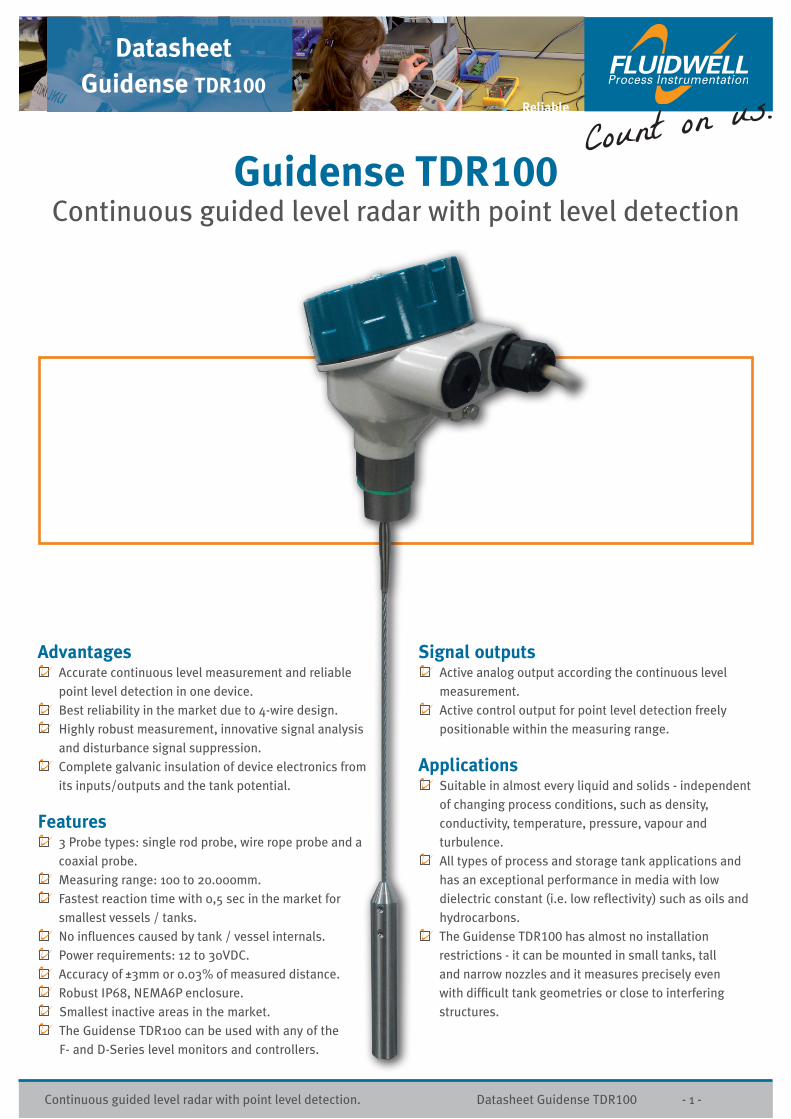
Guidense TDR100Continuous guided level radar with point level detection
Reliable
Advantages Accurate continuous level measurement and reliable point level detection in one device.
Best reliability in the market due to 4-wire design. Highly robust measurement, innovative signal analysis and disturbance signal suppression.
Complete galvanic insulation of device electronics from its inputs/outputs and the tank potential.
Features 3 Probe types: single rod probe, wire rope probe and a coaxial probe.
Measuring range: 100 to 20.000mm. Fastest reaction time with 0,5 sec in the market for smallest vessels / tanks.
No influences caused by tank / vessel internals. Power requirements: 12 to 30VDC. Accuracy of ±3mm or 0.03% of measured distance. Robust IP68, NEMA6P enclosure. Smallest inactive areas in the market. The Guidense TDR100 can be used with any of the
F- and D-Series level monitors and controllers.
Signal outputs Active analog output according the continuous level measurement.
Active control output for point level detection freely positionable within the measuring range.
Applications Suitable in almost every liquid and solids - independent of changing process conditions, such as density, conductivity, temperature, pressure, vapour and turbulence.
All types of process and storage tank applications and has an exceptional performance in media with low dielectric constant (i.e. low reflectivity) such as oils and hydrocarbons.
The Guidense TDR100 has almost no installation restrictions - it can be mounted in small tanks, tall and narrow nozzles and it measures precisely even with difficult tank geometries or close to interfering structures.

Continuous guided level radar with point level detection. Datasheet Guidense TDR100 - 2 -
General informationIntroduction Guidense TDR100The Guidense TDR100 is a guided level radar for continuous level measurement and point level detection in liquids and solids, with active analog and control output. It is very easy to install with a 4-wire system: a set of 2 wires for the power supply and separate sets of 2 wires for each output.
ConfigurationConfiguration of the Guidense TDR100 can be done directly with a set of DIP switches, a single push button and visual feedback from an LED. All settings required to get the sensor fully operational can be performed directly on the device.
Mechanical installationThe Guidense TDR100 is mounted vertically to the tank via its connection thread, which is screwed directly into a standard threaded tank connection, i.e. weld-in socket, or it can be screwed into a flange, which is connected to a tank nozzle.
Electrical installation TDR100The Guidense TDR100 is a 4-wire system: a set of 2 wires for the power supply and separate sets of 2 wires for each output. The wires are connected to the sensor electronic inside the housing via a screwless, cage clamp terminal block for stranded and solid wires 0,5 - 2mm2 / AWG 22 - 14.
Probe typesTo meet various application requirements, the Guidense TDR100 has three different probe types: single rod probe, wire rope probe and coaxial probe. The single rod probe is recommended for installations in liquids and in bypass chambers and stilling wells. The wire rope probe is recommended for installations in solids, tall tanks and where limited headroom is available. The coaxial probe is the ideal solution for a hassle-free ‘drop-in anywhere’ application; ensuring reliable measurement under almost all conditions. An extended temperature option, -200°C to +250°C, for the single rod and coaxial probe is available on request. For chemically aggressive and corrosive environments a single rod probe with PTFE coating is available on request.
Probe length and measuring range
L Probe length: Single rod probe: 100 to 3.000mm. Wire rope probe: 2.500 to 20.000mm. Coaxial probe: 100 to 6.000mm.I1 Inactive area top: Single rod probe εr = 80: 50mm / εr = 2: 80mm. Wire rope probe εr = 80: 50mm / εr = 2: 80mm. Coaxial probe εr = 80: 30mm / εr = 2: 50mm.I2 Inactive area bottom: Single rod probe εr = 80: 10mm / εr = 2: 50mm. Wire rope probe εr = 80: 10mm / εr = 2: 50mm. Coaxial probe εr = 80: 10mm / εr = 2: 50mm.M Measuring area: M = L - I1 - I2.S Switch point, freely positionable within the measuring
range (M) Default at 20% of [L].
Hazardous areasFor applications with hazardous gas or dust atmospheres an ATEX flameproof enclosure with ATEX II 1/2 G Ex ia/d IIC T6 Ga/Gb approval is available on request.
gasket
gasket
gasket
socket mounting nozzle mounting with flange
power supply
Control systeme.g. Fluidwell display
I1
I2
Reference point

Continuous guided level radar with point level detection. Datasheet Guidense TDR100 - 3 -
Mechanical specificationsMaterials house • Aluminium alloy EN AC-AlSi9Cu3.
Cover o-ring: silicone rubber.
• Stainless steel 1.4401 / 316.
Cover O-ring: silicone rubber.
Materials probe Single rod probe: SS 1.4404 / 316L, PEEK.
Single rod probe PTFE coated: PTFE, O-ring (request).
Wire rope probe: SS 1.4401 / 316, PEEK.
Coaxial probe: SS 1.4404 / 316L, PEEK, O-ring.
Gasket at connection thread: Klingersil C-4400, 2mm
Protective rating IP68 / NEMA6P.
Cable entries M20 x 1,5.
Conn. thread G 3/4 A or 3/4” NPT (wrench size 32mm).
Max. load Single rod probe: Max. lateral load 6Nm.
Wire rope probe: Max. tensile load 5kN.
Coaxial probe: Max. lateral load 100Nm.
Diameters Single rod probe: O/ 6mm.
Wire rope probe: O/ 4mm / counterweight: O/ 22mm.
Coaxial probe: O/ 17.2mm.
Dimensions Guidense TDR100
Application specificationsDielectric Single rod / wire rope probe: εr minimal 1,8.
constant Coaxial probe: εr minimal 1,4.
Conductivity No restrictions.
Density No restrictions.
Application Single rod / wire rope probe: -40°C to +150°C.
temperature Single rod, PTFE coated: -15°C to +100°C (on request).
Coaxial probe EPDM o-ring: -40°C to +130°C.
Coaxial probe FKM (Viton) o-ring: -15°C to +150°C.
Extended NBR o-ring: -200°C to +250°C (on request).
temperature FKM (Viton) o-ring: -150°C to +250°C (on request).
Ambient -25°C to +80°C.
temperature (storage: -40°C to +85°C).
Application -1bar to 40bar.
pressure (single rod probe PTFE coated: 0 to 4bar, on request).
Velocity of < 1.000mm/s
level change
Interface An oil layer of < 70mm thickness on top of water is
not detected by the sensor.
Dynamic Single rod / wire rope probe: < 5.000mPa s=5.000cP
viscosity Coaxial probe: < 500mPa s = 500cP.
Electrical specificationsAnalog output Active analog output according the continuous level
measurement.
Lower value 4,0mA (span 0%) - default at 10mm above probe end.
Upper value 20,0mA (span 100%) - default at 50mm below
reference point (shoulder of the connection thread).
Response time 0,5, 2 or 5 sec.
Temperature drift < 0,2mm/K change in ambient temperature.
Load resistance Approx. 250Ω.
Control output Active control output for point level detection
freely positionable within the measuring range.
Type Active PNP - NC [default] or NO (short-circuit protected).
Load current < 200mA.
Voltage HIGH Supply voltage - 2V.
Voltage LOW 0V to 1V.
Response time < 100ms.
Supply voltage 12 to 30V DC (reverse-polarity protected).
Current < 50mA at 24VDC.
consumption
Start-up time < 6 sec.
Cable terminals Stranded and solid wires 0,5 to 2mm2/AWG 22 to 14.
Measurement specificationsAccuracy ±3mm or 0.03% of measured distance, whichever is
greatest.
Repeatability < 2mm.
Resolution < 1mm.
Dimensions in mm
Reference point
DatasheetGuidense TDR100
Fluidwell Instruments bv
P.O. Box 6 • 5460 AA • Veghel
Voltaweg 23 • 5466 AZ • Veghel
The Netherlands
Telephone: +31 (0) 413 - 343 786
Telefax: +31 (0) 413 - 363 443
Email: [email protected]
Internet: www.fluidwell.comSpecifications are subject to change without notice.
Copyright: Fluidwell Instruments bv - 2014 - GUIDENSETDR100-DATA-EN-V1418
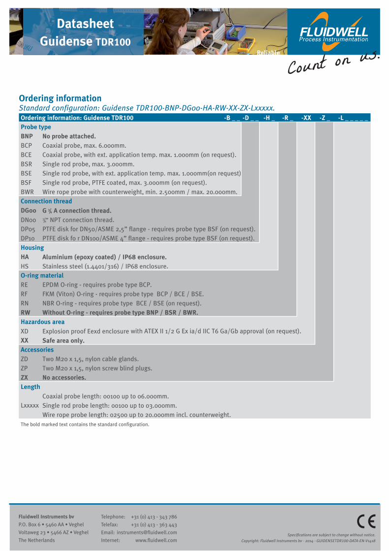
Ordering informationStandard configuration: Guidense TDR100-BNP-DG00-HA-RW-XX-ZX-Lxxxxx.Ordering information: Guidense TDR100 -B _ _ -D _ _ -H _ -R _ -XX -Z _ -L _ _ _ _ _Probe typeBNP No probe attached.BCP Coaxial probe, max. 6.000mm.BCE Coaxial probe, with ext. application temp. max. 1.000mm (on request).BSR Single rod probe, max. 3.000mm.BSE Single rod probe, with ext. application temp. max. 1.000mm(on request)BSF Single rod probe, PTFE coated, max. 3.000mm (on request).BWR Wire rope probe with counterweight, min. 2.500mm / max. 20.000mm.Connection threadDG00 G 3/4 A connection thread.DN00 3/4” NPT connection thread.DP05 PTFE disk for DN50/ASME 2,5” flange - requires probe type BSF (on request).DP10 PTFE disk fo r DN100/ASME 4” flange - requires probe type BSF (on request).HousingHA Aluminium (epoxy coated) / IP68 enclosure.HS Stainless steel (1.4401/316) / IP68 enclosure.O-ring materialRE EPDM O-ring - requires probe type BCP.RF FKM (Viton) O-ring - requires probe type BCP / BCE / BSE.RN NBR O-ring - requires probe type BCE / BSE (on request).RW Without O-ring - requires probe type BNP / BSR / BWR.Hazardous area
XD Explosion proof Eexd enclosure with ATEX II 1/2 G Ex ia/d IIC T6 Ga/Gb approval (on request).XX Safe area only.AccessoriesZD Two M20 x 1,5, nylon cable glands.ZP Two M20 x 1,5, nylon screw blind plugs.ZX No accessories.Length Coaxial probe length: 00100 up to 06.000mm.Lxxxxx Single rod probe length: 00100 up to 03.000mm. Wire rope probe length: 02500 up to 20.000mm incl. counterweight.The bold marked text contains the standard configuration.
Reliable