Embed Size (px)
Citation preview

®
Reliability Report No. 34
Q4 2000
M-RR-34-01
1
Overview ............................................................................................................................ 2Altera Quality Systems .................................................................................................... 2
Figure 1: Typical Product Flow Chart ......................................................................... 3Reliability Methodology .................................................................................................. 4
Table I: Reliability Qualification Requirements .......................................................... 5Table II: Reliability Monitor Program/Hermetic & Plastic Packages.......................... 6
Lifetest: Methodology and Failure Rate Prediction....................................................... 7Lifetest Methodology....................................................................................................... 7Failure Rate Prediction .................................................................................................... 8
Table III: Common Failure Mechanisms and Acceleration Factors............................ 9Lifetest Results............................................................................................................... 10
FLEX 0.5µ./0.42µ Products ....................................................................................... 10FLEX 0.3/0.35µ Products........................................................................................... 11FLEX and APEX 0.22/0.25µ Products....................................................................... 12APEX 0.18µ Products ................................................................................................ 13MAX 7000S and MAX 9000 - Third Generation....................................................... 14MAX 7000A - Fourth Generation .............................................................................. 15MAX 7000B - Fifth Generation ................................................................................ 16Classic and Configuration Devices - Second Generation........................................... 17Classic and Configuration Devices - Third Generation.............................................. 18Configuration Devices Flash Memory .................................................................... 19
High Temperature Storage............................................................................................. 20Reflow Simulation and Moisture Preconditioning....................................................... 22Accelerated Moisture Resistance ................................................................................... 23
Autoclave ....................................................................................................................... 23Unbiased HAST............................................................................................................. 23Temperature Humidity Bias........................................................................................... 27H.A.S.T. ......................................................................................................................... 29
Temperature Cycling ...................................................................................................... 32Latch-up ........................................................................................................................... 37
JEDEC 17 vs. 78............................................................................................................ 37Electrostatic Discharge ................................................................................................... 40
Human Body Model ESD........................................................................................... 40Charged Device Model............................................................................................... 40
2
OverviewAltera designs and manufactures Programmable Logic Devices (PLDs). These are user configurableintegrated circuits used to implement custom digital logic functions. Altera offers eight families of PLDsand a family of configuration Devices. These are all described in detail in the appropriate device datasheet. The Data Book describes device architecture, logic configuration elements, package and pinoutavailability, package outline drawings, thermal characteristics and other package attributes, handlingguidelines and surface mount guidelines, in addition to normal product data sheet specifications.
Product information, product change notifications, and support can also be found at Alteras Web site athttp://www.altera.com. Altera literature is available in Adobe Acrobat and postscript format. Literaturecan also be ordered by calling 1-800-3-ALTERA.
Altera Technical Support (ATLAS) is also available at Alteras web site and can be used to find answersto technical questions or to solve problems. Atlas currently provides both technical solutions andcustomer training information. Altera maintains a toll-free customer hotline for general assistance: 800-800-EPLD.
Altera has a closed loop Reliability System that conforms to the requirements of ISO 9001, MIL-I-45208and JEDEC standards. Altera and all of its major suppliers are ISO 9000 certified. Alteras Reliabilityqualification and monitoring programs are also governed by internal specifications, which defineprocedures, pass/fail requirements, and corrective actions. Altera has been ISO9001 certified sinceOctober, 1994. Alteras ISO 9001 auditors are the National Standards Authority of Ireland, NSAI.
Alteras corporate mission is to be the preferred supplier of leading edge programmable logic siliconsolutions and related software development tools. Altera strives to provide cost effective, state-of-the-artsolutions to its customers in a timely manner while consistently meeting or exceeding their quality,reliability, and service expectations.
Altera Quality SystemsAlteras quality system is designed to meet all the requirements of ISO 9001, and is described in AlterasQuality Manual, 11G-00000 (available through literature). Alteras quality systems have also beenreviewed and assessed in great detail by some of its major customers, which include multinationalcorporations from all over the world. Altera maintains complete on-line documentation and computeraided manufacturing systems to control product manufacturing. Internal specifications are in compliancewith applicable JEDEC standards. Alteras computer aided manufacturing enables complete fabricationand assembly lot traceability. Altera maintains a network of Applications and Quality engineeringpersonnel to support customers in the design, debug, manufacturing, and distribution of its products.
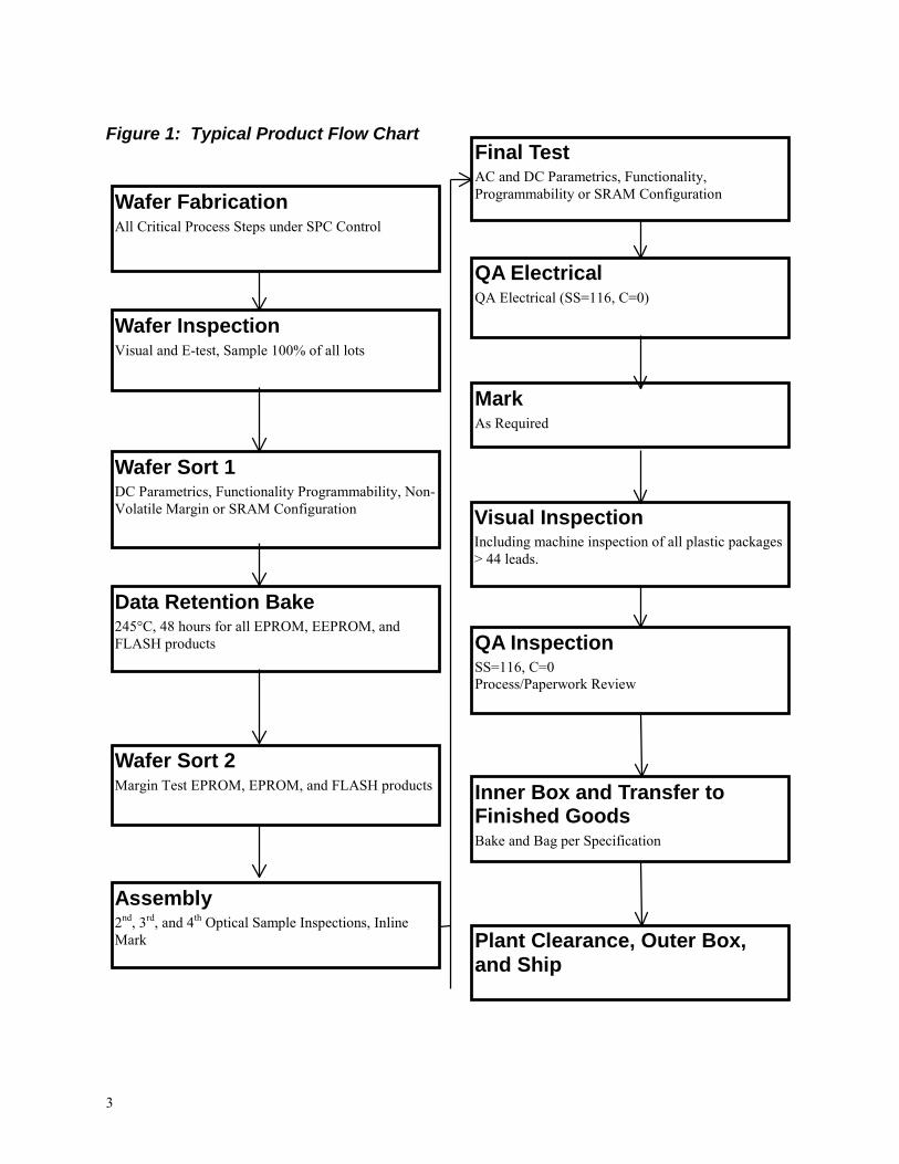
Altera performs comprehensive testing and manufacturing controls on all its products. Figure 1 shows atypical product manufacturing flow.
3
Figure 1: Typical Product Flow Chart
Wafer InspectionVisual and E-test, Sample 100% of all lots
Wafer Sort 1DC Parametrics, Functionality Programmability, Non-Volatile Margin or SRAM Configuration
Data Retention Bake245°C, 48 hours for all EPROM, EEPROM, andFLASH products
Wafer Sort 2Margin Test EPROM, EPROM, and FLASH products
Assembly2nd, 3rd, and 4th Optical Sample Inspections, InlineMark
QA ElectricalQA Electrical (SS=116, C=0)
Final TestAC and DC Parametrics, Functionality,Programmability or SRAM Configuration
MarkAs Required
Visual InspectionIncluding machine inspection of all plastic packages> 44 leads.
QA InspectionSS=116, C=0Process/Paperwork Review
Inner Box and Transfer toFinished GoodsBake and Bag per Specification
Plant Clearance, Outer Box,and Ship
Wafer FabricationAll Critical Process Steps under SPC Control

4
Reliability MethodologyReliability qualifications and monitoring are performed on a Product Family basis. All members of aproduct family utilize the same circuit architecture, fabrication process, and share the same package types.Alteras product families are Classic, MAX 7000, MAX 9000, FLEX 6000, FLEX 8000, FLEX 10K,ACEX 1K and APEX 20K. A product family will contain several products all based upon the same logicelements, embedded storage elements, and programmable interconnect technology. Product families have3 to 10 members, with a range of densities and packaging options. For reliability purposes such as datareporting and failure rate prediction, a product family will be reported on a fabrication processtechnology. The fabrication process is described by the storage element technology (i.e. SRAM,EPROM, or EEPROM) and feature size (i.e. 0.5µ or 0.35µ).
Product families are qualified based upon the requirements specified in Table I. Reliability monitors arebased on the schedules specified in Table 2. Product family qualification will include products with arange of densities, package types, and package leadcounts. If a new product is added to the productfamily with a significant increase (at least 2X) in logic elements, a product qualification will beperformed.
Customers are notified of changes to products through Alteras Product Change Notification system.Notifications are based on changes affecting form, fit, or function. Notifications are also found atAlteras Web site at www.altera.com.
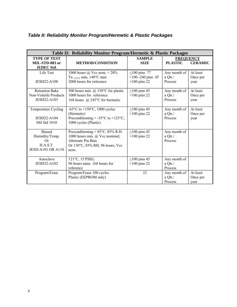
Reliability Monitors are performed on a regular basis in order to assure that Alteras normal productiontesting and process control methodologies produce reliable product. The Reliability monitor program isalso based upon a product family methodology. Different products and package types are procured fromnormal production on a Last In First Out (LIFO) schedule to monitor product reliability. Results in thisreport cover data gathered in the last 18 months.

5
Table I: Reliability Qualification Requirements
Table I: Reliability Qualification RequirementsTYPE OF TEST Full Qualification Level 1 QualificationMIL-STD-883or JEDEC Std.
METHOD/CONDITION SAMPLESIZE
#of
Lots
AcceptCriteria
# Rej./Lot
#of
Lots
Accept/RejectCriteria (LTPD)
Life TestProgrammed
JESD22-A108
1000 hours @ Vcc+20%,Ta:125°C min, 140°C max2000 hours for reference
<100 pins 77>100 - 240 pins 45>240 pins 25
3 110
< 200FIT@55°C
4 All Lots CombinedLTPD 30/76,1/129,, or2/175< 100 FIT @55°C
Retention BakeNon-volatiledevices only
JESD22-A103
1000 hours min. @ 150°C forPlastic,168 hours min @ 245°C forHermetic or wafer level maybe substituted.
<100 pins 45>100 pins 25
3 10
3 All Lots combinedLTPD 30/76, 1/129, or2/175
TemperatureCycling
JESD22-A104Mil Std 1010
-65°C to +150°C, 1000cycles (Hermetic)Preconditioning + 1000cycles. (Plastic)-55°C to+125°C Ind, 0°C to +125°CCommercial
<100 pins 45>100 pins 25
3 10
3 1000 Cycles,LTPD 70//32, 1/55, or 2/75
BiasedHumidity/Temp.
OrH.A.S.T
JESD-A101 orA110
Preconditioning + 85°C,85% R.H.; 1000 hours min.@ Vcc nominal;Alternate Pin BiasOr 130°C, 85% RH, 96hours, Vcc nom.
<100 pins 45>100 pins 25
3 10
3 All Lots combinedLTPD 30/75, 1/129, or2/175
Autoclave
JESD22-A102
121°C, 15 PSIG;96 hours, 168 hours forreference
<100 pins 45>100 pins 25
3 10
3 All Lots CombinedLTPD 70//32, 1/55, or 2/75
ESD HBMJESD22-A114Mil Std 3015.7
100pf, & 1500Ω. RecordDistribution of all FailingPins
3 1 1000V min. 1 2000V min.
ESD ChargedDevice
ModelJESD22-C101
field Induced Charge Device 3 1 500Vmin 3 1000Vmin
Latch-upJESD 78
(Icc nom. + 100mA) or Iccnom. + 50% on I/O, Vcc +50% on Power Supplies
6 1 0 3 0/10
Program/EraseCycling
Program/Erase 100 cyclesPlastic (EEPROM only)
25 1 0
PCB InterconnectReliability
JESD22-A104
0°C to +100°C, SingleChamber
25 1DaisyChain
>2000 Cyclesto
0.1%PredictedFailure
6
Table II: Reliability Monitor Program/Hermetic & Plastic Packages
Table II: Reliability Monitor Program/Hermetic & Plastic PackagesTYPE OF TESTMIL-STD-883 or
JEDEC Std.METHOD/CONDITION
SAMPLESIZE
FREQUENCYPLASTIC CERAMIC
Life Test
JESD22-A108
1000 hours @ Vcc nom. + 20%Ta :125°C min, 140°C max2000 hours for reference
<100 pins 77>100 -240 pins 45>240 pins 22
Any month ofa Qtr./Process
At leastOnce peryear
Retention BakeNon-Volatile Products
JESD22-A103
500 hours min. @ 150°C for plastic1000 hours for reference168 hours @ 245°C for hermetic
<100 pins 45>100 pins 22
Any month ofa Qtr./Process
At leastOnce peryear
Temperature Cycling
JESD22-A104Mil Std 1010
-65°C to +150°C, 1000 cycles(Hermetic)Preconditioning + -55°C to +125°C,1000 cycles (Plastic)
<100 pins 45>100 pins 22
Any month ofa Qtr./Process
At leastOnce peryear
BiasedHumidity/Temp.
OrH.A.S.T.
JESD-A101 OR A110
Preconditioning + 85°C, 85% R.H.1000 hours min. @ Vcc nominal;Alternate Pin BiasOr 130°C, 85% RH, 96 hours, Vccnom.
<100 pins 45>100 pins 22
Any month ofa Qtr./Process
AutoclaveJESD22-A102
121°C, 15 PSIG;96 hours mins. 168 hours forreference
<100 pins 45>100 pins 22
Any month ofa Qtr./Process
Program/Erase Program/Erase 100 cyclesPlastic (EEPROM only)
22 Any month ofa Qtr./Process
At leastOnce peryear

7
Lifetest: Methodology and Failure Rate Prediction
Lifetest MethodologyAltera performs a high temperature / high voltage Lifetest on its products to accelerate failuremechanisms. Failure mechanisms are accelerated by elevating the ambient temperature of theLifetest chamber to at least 120°C, in order to increase the junction temperature to at least 130°C,and by increasing the voltage of the Vcc power supply by 20%. The Lifetest boards have specialhigh temperature sockets that maintain lead integrity.
Alteras devices, which are programmable, generally require a logic configuration to beprogrammed into them to electrically exercise the internal logic elements. A logic configurationis developed that will work in combination with several externally supplied input signals toexercise the internal circuitry. This logic configuration is programmed into the device usingAlteras MAX+PLUS II software and hardware, exactly as would be used by a customer.
MAX 7000 and MAX 9000 devices, which are EEPROM devices, are first subjected to 100Program Erase Cycles before starting Lifetest.
Each device is tested using production test equipment to data sheet specifications before beingstressed. All readouts are also done on the same production test equipment to data sheetparameters. A device is considered a failure if it does not pass data sheet specifications.
For non-volatile configuration elements, there is a test mode that allows the configurationelements to be margin tested to determine the amount of charge on the floating gate. At eachreadout the margin of every configuration element is tested and the lowest margin is recorded.

8
Failure Rate PredictionAltera uses industry standard techniques for failure rate prediction. Failure rates are predictedbased upon an exponential distribution of failures in time (constant failure rate).
As noted above, both elevated temperatures and voltages are used to accelerate failures in lifetest,and the overall acceleration is simply the product of the thermal and voltage acceleration:
Equivalent Hours in typical use conditions = (Hours in lifetest) x (Acceleration factor)
Acceleration Factor = (Thermal Acceleration) x (Voltage Acceleration)
Thermal and voltage acceleration factors are based on standard acceleration formulas andpublished acceleration factors. Acceleration Factors are based upon JEDEC Publication JEP122.The formulas are presented below, and the acceleration factors are listed in Table III.
Note that a dielectric breakdown acceleration factor of 0.7eV is used. Recently published papershave demonstrated that modern oxides have a higher thermal activation energy than thepreviously reported 0.3eV. Values of 0.3eV to 0.9eV have been reported. i ii Altera has verifiedthrough multiple temperature Burn-In studies that 0.7eV is applicable to Altera devices.
Junction temperatures, not ambient temperatures, must be used in calculating thermal accelerationfactors. Junction temperatures are calculated using actual power dissipation under stressconditions, and typical power dissipation under use conditions with the turbo-bit on. (This isfairly conservative since many applications will set the turbo-bit off, significantly reducing powerconsumption as shown in the Databook Icc curves.) Junction temperatures are calculated fromambient temperature or case temperature measurements using the thermal resistance values foundin the Altera Databook in the General Information section. Thermal resistance values arespecific to each product and package combination. For convenience, formulas to calculatejunction temperatures are included with the acceleration formulas below.
Note also that temperatures must be converted to Degrees Kelvin when using the TemperatureAcceleration formula below. Degrees Kelvin = Degrees Centigrade + 273.
Temperature Acceleration Factor = exp[Ea/((k)(Toperation)) - Ea/((k)(Tstress))]
k = Boltzmanns constant = 8.62 x 10⁻⁵ eV/°KEa = Activation energy in eV (see Table III)T = Junction Temperature in Degrees KelvinkT(eV) = 0.0258 x (temperature in Centigrade + 273)/298
Gate Oxide Voltage Acceleration Factor = exp[(γ/tox/10 nm)(Vstress - Voperation)]
γ = Voltage exponent factor (see Table III)
Interlayer Dielectric Acceleration Factor = exp[(γ)(Vstress - Voperation)]
Junction Temperature = (Ambient Temperature)+(Power dissipation)*(θja) = (Case Temperature)+(Power dissipation)*(θjc)
θja and θjc are found in the Databook in the General Information Section.

9
Table III: Common Failure Mechanisms and Acceleration FactorsMechanism Activation Energy “Ea” Voltage Exponent Factor
Gate Oxide Breakdown 0.7 γ = 3.2Interlayer defect 0.5 γ = 2.0Silicon Junction Defect 0.8 0.0Masking (Poly, Diffusion, etc.) 0.5 0.0Metallization Defect 0.5 0.0Electromigration 0.5 (Al-Si), 0.7 (Al-Cu) Current density dependence (J 2 )Contamination (Surface & Bulk) 1.0 0.0Charge Loss 0.6 0.0Hot Electron -0.06 Substrate current dependence (Isub n)
Failure rates are calculated on a product family basis (as in the tables of data on the followingpages). Device hours accumulated at the stress conditions are converted to normal use conditionsusing the acceleration factors described above. Equivalent hours are calculated at a typical usecondition of Vcc nominal in a 55°C still-air ambient.
Failure mechanisms are determined by failure analysis. For each failure mechanism observed instress, the acceleration factor is calculated using the formulas and acceleration factors above. Iftwo failure mechanisms are active, the failure rate due to each one is summed to produce acombined failure rate.
Failure rates are expressed in terms of FITs or Failures In Time, where one FIT is equivalent toone failure in one billion or 109 device-hours.
The failure rate is calculated using a Chi-squared distribution to predict a 60% confidence levelfrom the small number of failures and limited sample size of the population tested. The Chi-squared value is calculated from the inverse Chi-squared distribution using the desired probabilitylevel and the degrees of freedom. iii The degrees of freedom are calculated as: ν= 2n+2, wheren= # of failures observed. The failure rate is then calculated from the Chi-squared value:
( )Failure RateA F Device hours
failureshour=
∗ ∗Χ 2
2 . .
The FIT rate is 109*Failure Rate and the Mean Time to Failure is simply the inverse of the failurerate for an exponential distribution.
10
Lifetest ResultsLifetest Results are reported by Product Family. Where a product family is produced on differentwafer fabrication technologies the results are reported separately for each fabrication technology.Within a product family the same logic configuration elements, macrocells, and programmableinterconnect are used. The only variable is the size of the product, with each family having 3 to10 different numbers of macrocells or logic elements. A brief description of the product familyand process technology is included in each section.
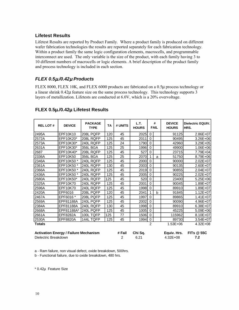
FLEX 0.5µµµµ./0.42µµµµ ProductsFLEX 8000, FLEX 10K, and FLEX 6000 products are fabricated on a 0.5µ process technology ora linear shrink 0.42µ feature size on the same process technology. This technology supports 3layers of metallization. Lifetests are conducted at 6.0V, which is a 20% overvoltage.
FLEX 0.5µµµµ./0.42µµµµ Lifetest Results
REL LOT # DEVICE PACKAGE TYPE TA # UNITS L.T.
HOURSDEVICE HOURS
Dielectric EQUIV. HRS.
2495A EPF10K10 208L PQFP 120 45 2025 0 91125 2.86E+072572A EPF10K20* 208L RQFP 125 45 2011 0 90495 3.26E+062573A EPF10K30* 240L RQFP 125 24 1790 0 42960 3.29E+052631A EPF10K30* 356L BGA 125 25 1996 0 49900 1.06E+062687 EPF10K40* 208L RQFP 125 45 527 0 23715 7.79E+042336A EPF10K50 356L BGA 125 25 2070 1 a 51750 8.79E+062346A EPF10K50 * 240L RQFP 125 45 2000 0 90000 2.02E+072361A EPF10K50 * 240L RQFP 130 45 2003 0 90135 2.60E+072366A EPF10K50 * 240L RQFP 125 45 2019 0 90855 2.04E+072436A EPF10K50 * 240L RQFP 125 45 2005 0 90225 2.02E+072680A EPF10K50* 240L RQFP 125 45 520 0 23400 5.25E+062325A EPF10K70 240L RQFP 125 45 2001 0 90045 1.89E+072596A EPF10K70 240L RQFP 125 45 1998 0 89910 1.89E+072420A EPF6016 208L PQFP 120 45 2041 1 b 91845 1.12E+072467A EPF6016 * 208L PQFP 125 45 1997 0 89865 1.41E+072569A EPF81188A 240L PQFP 125 45 2002 0 90090 4.96E+072384A EPF81188A 240L RQFP 130 45 1998 0 89910 6.38E+072668A EPF81188A* 240L PQFP 125 45 1005 0 45225 5.09E+062661A EPF8282A 100L TQFP 125 77 1506 0 115962 8.10E+072530A EPF8820A 144L TQFP 125 45 1994 0 89730 3.54E+07Totals 2 1.53E+06 4.32E+08
Activation Energy / Failure Mechanism # Fail Chi Sq. Equiv. Hrs. FITs @ 55CDielectric Breakdown 2 6.21 4.32E+08 7.2
a - Ram failure, non visual defect, oxide breakdown, 500hrs.b - Functional failure, due to oxide breakdown, 480 hrs.
* 0.42µ Feature Size
# FAIL

11
FLEX 0.3/0.35µµµµ ProductsFLEX 10KA and FLEX 6000A products are fabricated on a 0.3/0.35µ process technology thatsupports up to 4 layers of metallization. The process technology operates with a 3.3V supplyvoltage and has I/Os that are 2.5V and 5.0V tolerant. Devices are available in TQFP, QFP,RQFP, FBGA and BGA packages with logic density ranging from 576 LEs to 12,160 LEs.Lifetests are conducted at 4.0V, which is a 20% overvoltage.
FLEX 0.3/0.35µµµµ Lifetest Results
REL LOT # DEVICE PACKAGE TYPE TA # UNITS L.T.
HOURSDEVICE HOURS
Dielectric EQUIV. HRS.
2501A EPF10K100A 240L RQFP 125 25 1998 0 49950 5.64E+072583A EPF10K100A 240L RQFP 125 25 1591 0 39775 4.49E+072588A EPF10K100A 240L RQFP 125 25 1582 0 39550 4.47E+072590B EPF10K100A 240L RQFP 125 45 1998 0 89910 1.02E+082404A EPF10K100A 356L BGA 125 25 2004 0 50100 4.71E+072565A EPF10K100A 484L FBGA 125 24 2009 0 48216 3.36E+072337A EPF10K100A 600L BGA 125 25 2001 1 c 50025 5.15E+072522A EPF10K100A 600L BGA 125 25 2006 0 50150 5.17E+072670A EPF10K30A 256L FBGA 125 25 492 0 12300 6.33E+062524A EPF10K30A 356L BGA 125 25 2023 0 50575 4.69E+072256F EPF10K30A 484L FBGA 125 41 2051 0 84091 5.19E+072351A EPF10K30A 484L FBGA 125 25 2047 0 51175 3.16E+072397A EPF10K50V 240L PQFP 130 45 2064 1 d 92880 2.48E+072560A EPF10K50V 240L RQFP 125 50 2012 0 100600 8.08E+072639A EPF10K50V 356L BGA 125 25 2009 0 50225 2.76E+072355A EPF6016A 144L TQFP 120 45 2053 0 92385 1.08E+082350A EPF6024A 208L PQFP 125 45 2002 0 90090 1.37E+082460 EPF6024A 208L PQFP 125 100 164 0 16400 2.49E+072552A EPF6024A 208L PQFP 125 45 2020 0 90900 1.38E+08
2 1.15E+06 1.11E+09
Activation Energy / Failure Mechanism # Fail Chi Sq. Equiv. Hrs. FITs @ 55CDielectric Breakdown 2 6.21 1.11E+09 2.8
c - RAM failure, non-visual defect, oxide breakdown, 408 hrs.d - Input Short, non visual defect, oxide breakdown, 2064 hrs.
# FAIL

12
FLEX and APEX 0.22/0.25µµµµ ProductsFLEX 10KB, 10KE, and APEX 20K products are fabricated on a 0.22/0.25µ process technologythat supports up to 5 layers of metallization. Devices are available in TQFP, QFP, RQFP, FBGAand BGA packages with logic density ranging from 1728 LEs to 16,640 LEs. The processtechnology operates with a 2.5V supply. Lifetests are conducted at 3.0V, which is a 20%overvoltage
FLEX and APEX 0.22/0.25µµµµ Lifetest Results
REL LOT # DEVICE PACKAGE TYPE TA # UNITS L.T.
HOURSDEVICE HOURS
Dielectric EQUIV. HRS.
2655A EP1K100 208L PQFP 125 45 1500 0 67500 4.88E+072422A EP20K100 240L PQFP 125 25 2016 0 50400 4.41E+072646A EP20K100 240L PQFP 125 45 476 0 21420 1.88E+072676A EP20K100 356L BGA 125 25 495 0 12375 1.59E+072633A EP20K200 240L RQFP 125 22 1486 0 32692 6.35E+062456A EP20K400 652L BGA 125 25 2009 0 50225 1.61E+072533A EP20K400 652L BGA 125 25 1378 0 34450 1.10E+072635A EP20K400 652L BGA 125 25 2002 0 50050 1.60E+072309A EPF10K100B 208L PQFP 130 24 2048 0 49152 5.90E+072324A EPF10K100B 240L PQFP 125 45 2003 0 90135 9.08E+072329A EPF10K100B 240L PQFP 125 45 2015 1 e 90675 9.14E+072532A EPF10K100E 240L PQFP 125 25 2019 0 50475 4.05E+072536A EPF10K100E 240L PQFP 125 42 1296 0 54432 4.37E+072415A EPF10K100E 240L RQFP 125 25 2008 0 50200 4.03E+072446A EPF10K100E 240L RQFP 125 24 1999 0 47976 3.85E+072388A EPF10K130E 240L PQFP 125 24 1996 0 47904 6.88E+072413A EPF10K130E 240L PQFP 125 25 2010 0 50250 7.21E+072445A EPF10K130E 240L PQFP 125 25 2063 0 51575 7.41E+072523A EPF10K130E 600L BGA 125 25 990 0 24750 3.55E+072539A EPF10K200S 240L RQFP 125 28 2031 0 56868 4.27E+072378A EPF10K50E 240L PQFP 125 45 1997 0 89865 1.21E+082660A EPF10K50E 240L PQFP 125 45 512 0 23040 3.09E+07
1 1.03E+06 9.77E+08
Activation Energy / Failure Mechanism # Fail Chi Sq. Equiv. Hrs. FITs @ 55CDielectric Breakdown 1 4.04 9.77E+08 2.1
e - Lookup table Failure, non-visual defect, 1060hrs.
# FAIL
13
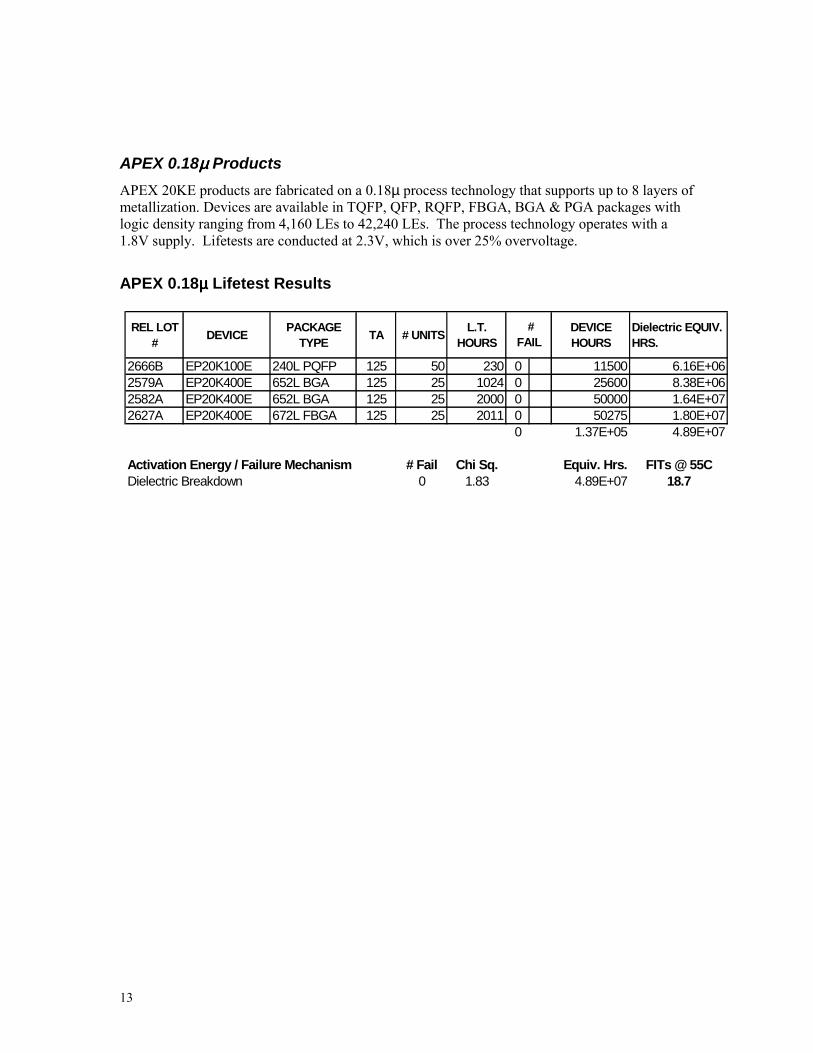
APEX 0.18µµµµ ProductsAPEX 20KE products are fabricated on a 0.18µ process technology that supports up to 8 layers ofmetallization. Devices are available in TQFP, QFP, RQFP, FBGA, BGA & PGA packages withlogic density ranging from 4,160 LEs to 42,240 LEs. The process technology operates with a1.8V supply. Lifetests are conducted at 2.3V, which is over 25% overvoltage.
APEX 0.18µµµµ Lifetest Results
REL LOT # DEVICE PACKAGE
TYPE TA # UNITS L.T. HOURS
DEVICE HOURS
Dielectric EQUIV. HRS.
2666B EP20K100E 240L PQFP 125 50 230 0 11500 6.16E+062579A EP20K400E 652L BGA 125 25 1024 0 25600 8.38E+062582A EP20K400E 652L BGA 125 25 2000 0 50000 1.64E+072627A EP20K400E 672L FBGA 125 25 2011 0 50275 1.80E+07
0 1.37E+05 4.89E+07
Activation Energy / Failure Mechanism # Fail Chi Sq. Equiv. Hrs. FITs @ 55CDielectric Breakdown 0 1.83 4.89E+07 18.7
# FAIL

14
MAX 7000S and MAX 9000 - Third Generation
These MAX 7000 and MAX 9000 products are fabricated on a 0.5µ triple layer metal CMOSEEPROM process. Devices are available in logic densities from 32 to 560 macrocells and inPLCC, TQFP, PQFP, RQFP, and PGA packages. Lifetests are conducted at 6.0V, which is a20% overvoltage.
Third Generation MAX 7000 & MAX 9000 Lifetest Results
REL LOT# DEVICE PACKAGE TYPE TA #
UNITSL.T.
HOURSDEVICE HOURS
Dielectric Equiv. Hrs.
C.L. Equiv Hrs.
2675A EPM7032S 44L PLCC 125 77 500 0 38500 2.97E+07 1.28E+062367A EPM7032S 44L TQFP 120 77 1992 0 153384 8.76E+07 3.94E+062496A EPM7064S 100L TQFP 120 77 1998 0 153846 9.43E+07 4.20E+062544A EPM7064S 44L PLCC 120 77 1992 0 153384 9.03E+07 4.05E+062630A EPM7064S 44L TQFP 125 77 1998 0 153846 1.07E+08 4.67E+062546 EPM7064S 84L PLCC 125 77 2010 0 154770 1.26E+08 5.39E+062363A EPM7128S 100L PQFP 120 77 2004 0 154308 7.82E+07 3.58E+062617A EPM7128S 100L PQFP 125 77 2002 0 154154 9.60E+07 4.27E+062553A EPM7128S 100L TQFP 125 77 1993 0 153461 1.01E+08 4.44E+062334A EPM7128S 84L PLCC 120 77 1997 0 153769 8.77E+07 3.95E+062371A EPM7128S 84L PLCC 120 77 2068 0 159236 9.08E+07 4.09E+062437A EPM7128S 84L PLCC 125 77 2001 0 154077 1.10E+08 4.78E+062470A EPM7192S 160L PQFP 125 45 1983 2 f 89235 9.19E+06 5.28E+052664A EPM7192S 160L PQFP 125 45 1001 0 45045 4.64E+06 2.67E+052343A EPM7256S 208L PQFP 120 44 2002 0 88088 1.09E+07 6.13E+052403A EPM7256S 208L PQFP 125 45 2010 0 90450 1.41E+07 7.64E+052466A EPM9320A 208L RQFP 125 45 2094 0 94230 2.35E+07 1.19E+062688A EPM9320A 208L RQFP 125 45 168 0 7560 1.88E+06 9.54E+042356A EPM9560A 208L RQFP 120 45 1998 0 89910 1.79E+07 9.38E+052465A EPM9560A 356L BGA 125 24 2094 0 50256 1.36E+07 6.81E+052535A EPM9560A 356L BGA 125 24 2005 0 48120 1.30E+07 6.52E+052564A EPM9560A 356L BGA 125 25 2000 0 50000 1.35E+07 6.78E+05Totals 2 2.39E+06 1.22E+09 5.50E+07
Activation Energy / Failure Mechanism # Fail Chi Sq. Equiv. Hrs. FITs Dielectric Breakdown 0 1.83 1.22E+09 0.80.6eV / Charge Loss 2 6.21 5.50E+07 56.4Combined Failure Rate 57.2
f - 2 units failed, due to charge loss, 1001hrs
# Fail

15
MAX 7000A - Fourth GenerationThe MAX 7000A products are fabricated on a 0.35µ CMOS EEPROM process. This processsuppoerts up to four layers of metallization, which supports a 3.3V operating voltage. Devicesare available in logic densities from 32 to 512 macrocells and in PLCC, TQFP, PQFP, BGA, andFBGA packages. Lifetest are conducted at 4.0V, which is a 20% overvoltage.
Fourth Generation MAX 7000 Lifetest Results
REL LOT# DEVICE PACKAGE TYPE TA # UNITS L.T.
HOURSDEVICE HOURS
Dielectric Equiv. Hrs.
C.L. Equiv Hrs.
2405A EPM3256A 144L TQFP 125 70 2006 0 140420 1.95E+07 2.91E+062405B EPM3256A 144L TQFP 125 35 2032 0 71120 1.21E+07 1.76E+062332A EPM7032AE 44L PLCC 120 77 2004 0 154308 2.89E+07 4.12E+062332C EPM7032AE 44L PLCC 120 45 2063 0 92835 1.74E+07 2.48E+062448A EPM7032AE 44L TQFP 125 77 2000 0 154000 3.51E+07 4.87E+062570A EPM7064AE 44L PLCC 125 77 1990 0 153230 2.84E+07 4.06E+062344A EPM7128A 100L TQFP 120 77 1995 0 153615 1.92E+07 2.91E+062268C EPM7128A 144L TQFP 120 69 2020 0 139380 2.04E+07 3.02E+062386A EPM7128A 144L TQFP 120 45 2048 0 92160 1.35E+07 2.00E+062517A EPM7128A 144L TQFP 120 45 2006 0 90270 1.32E+07 1.95E+062401A EPM7128A 84L PLCC 125 77 1981 0 152537 2.78E+07 3.99E+062401B EPM7128A 84L PLCC 125 77 2002 0 154154 2.81E+07 4.03E+062266A EPM7256A 144L TQFP 120 45 2010 0 90450 6.10E+06 1.01E+062266C EPM7256A 144L TQFP 120 45 2017 0 90765 6.12E+06 1.01E+062293A EPM7256A 208L PQFP 120 45 2007 0 90315 5.67E+06 9.46E+052478A EPM7256A 256L FBGA 125 25 2016 0 50400 7.94E+06 1.16E+062349A EPM7256A 256L FBGA 120 45 1526 0 68670 8.39E+06 1.27E+062381A EPM7256A 256L FBGA 120 45 997 0 44865 5.48E+06 8.31E+052643B EPM7256AE 144L TQFP 125 50 178 0 8900 7.70E+05 1.23E+052316A EPM7512AE 208L PQFP 120 21 2033 1 g 42693 2.69E+06 4.48E+052316C EPM7512AE 208L PQFP 120 24 1995 0 47880 2.95E+06 4.94E+052353A EPM7512AE 208L PQFP 120 45 2013 0 90585 5.59E+06 9.34E+052369A EPM7512AE 208L PQFP 120 35 2018 0 70630 4.36E+06 7.28E+052374B EPM7512AE 208L PQFP 120 45 2032 0 91440 5.64E+06 9.43E+052452A EPM7512AE 208L PQFP 125 35 2000 0 70000 5.49E+06 8.86E+052520 EPM7512AE 208L PQFP 120 105 1915 0 201075 1.24E+07 2.07E+062402A EPM7512AE 256L BGA 125 25 2048 0 51200 5.17E+06 8.05E+052574A EPM7512AE 256L BGA 125 25 1008 0 25200 2.54E+06 3.96E+052654A EPM7512AE 256L BGA 125 25 1495 0 37375 3.77E+06 5.88E+052383A EPM7512AE 256L FBGA 120 38 2009 0 76342 5.70E+06 9.27E+052586A EPM7512AE 256L FBGA 125 25 508 0 12700 1.21E+06 1.90E+05Totals 1 2.81E+06 3.62E+08 5.38E+07
Activation Energy / Failure Mechanism # Fail Chi Sq. Equiv. Hrs. FITs Dielectric Breakdown 1 4.04 3.62E+08 5.60.6eV / Charge Loss 0 1.83 5.38E+07 17.0Combined Failure Rate 22.6
g - Intermetatic leakage failure, dielectric brakdown, 168hrs.
This table has c=2 calculations
# Fail

16
MAX 7000B - Fifth GenerationThese MAX 7000B products are fabricated on a 0.22µ quadruple layer metal CMOS EEPROMprocess. Devices are available in logic densities from 32 to 512 macrocells and in PLCC, TQFP,UBGA, PQFP & FBGA packages. Lifetests are conducted at 3.0V, which is over 35%overvoltage
Fifth Generation MAX 7000 Lifetest Results
REL LOT# DEVICE PACKAGE TYPE TA #
UNITSL.T.
HOURSDEVICE HOURS
Dielectric Equiv. Hrs.
C.L. Equiv Hrs.
2614A EPM7128B 144L TQFP 125 96 160 0 15360 4.88E+06 6.45E+052614B EPM7128B 144L TQFP 125 69 160 0 11040 3.51E+06 4.64E+052614F EPM7128B 144L TQFP 125 96 994 0 95424 3.03E+07 4.01E+062645 EPM7128B 144L TQFP 125 69 1814 0 125166 3.98E+07 5.26E+062645A EPM7128B 144L TQFP 125 66 1005 0 66330 2.11E+07 2.79E+062665B EPM7128B 144L TQFP 125 50 178 0 8900 2.83E+06 3.74E+052632A EPM7512B 208L PQFP 125 70 1049 0 73430 1.81E+07 2.48E+062632B EPM7512B 208L PQFP 125 35 1002 0 35070 6.01E+06 8.68E+052678A EPM7512B 208L PQFP 125 62 504 0 31248 7.71E+06 1.06E+062678B EPM7512B 208L PQFP 125 35 507 0 17745 3.04E+06 4.39E+05Totals 0 4.80E+05 1.37E+08 1.84E+07
Activation Energy / Failure Mechanism # Fail Chi Sq. Equiv. Hrs. FITs Dielectric Breakdown 0 1.83 1.37E+08 6.70.6eV / Charge Loss 0 1.83 1.84E+07 49.8Combined Failure Rate 56.5
This table has c=2 calculations
# Fail

17
Classic and Configuration Devices - Second GenerationThese Classic Products and some configuration devices have been fabricated on this 0.65µ doublelayer metal CMOS EPROM process. These devices are erasable with UV light when supplied inwindowed hermetic packages for prototyping. Lifetests are conducted at least 6.0V, which is aminimum of 20% overvoltage.
Second Generation Classic and Configuration Devices Lifetest Results
REL LOT# DEVICE PACKAGE TYPE TA #
UNITSL.T.
HOURSDEVICE HOURS
Dielectric Equiv. Hrs.
C.L. Equiv. Hrs.
Sil.Junc. Equiv Hrs.
2294A EP1810 68L PLCC 130 77 2034 0 156618 1.86E+08 1.09E+07 4.47E+072406A EP1810 68L PLCC 130 77 2065 0 159005 1.89E+08 1.10E+07 4.54E+072669A EP1810 68L PLCC 125 77 506 0 38962 2.56E+07 1.63E+06 5.65E+062354A EP910 44L PLCC 130 77 1995 0 153615 9.18E+07 5.92E+06 2.00E+072615A EP910 44L PLCC 130 77 2026 0 156002 9.32E+07 6.01E+06 2.03E+072318A EPC1 20L PLCC 125 77 1000 1 h 77000 5.06E+07 3.22E+06 1.12E+072385A EPC1 20L PLCC 130 77 2013 1 I 155001 1.31E+08 8.04E+06 3.00E+072338A EPC1441 8L PDIP 125 77 1991 0 153307 1.01E+08 6.40E+06 2.22E+072468A EPC1441 8L PDIP 125 77 2000 0 154000 1.01E+08 6.43E+06 2.23E+07Totals 2 1.20E+06 9.69E+08 5.96E+07 2.22E+08
Activation Energy / Failure Mechanism # Fail Chi Sq. Equiv. Hrs. FITsDielectric Breakdown, Intermetal Defect 0 1.83 9.69E+08 0.9Silicon Junction Defect 2 6.21 2.22E+08 14.00.6eV / Charge Loss 0 1.83 5.96E+07 15.4Combined Failure Rate 30.3
h - Functional failure, due to resistive/open diffusion contact, 552hrs.i - Program/Verify failure, due to resistive/open diffusion contact, 2013hrs.
# FAIL
18
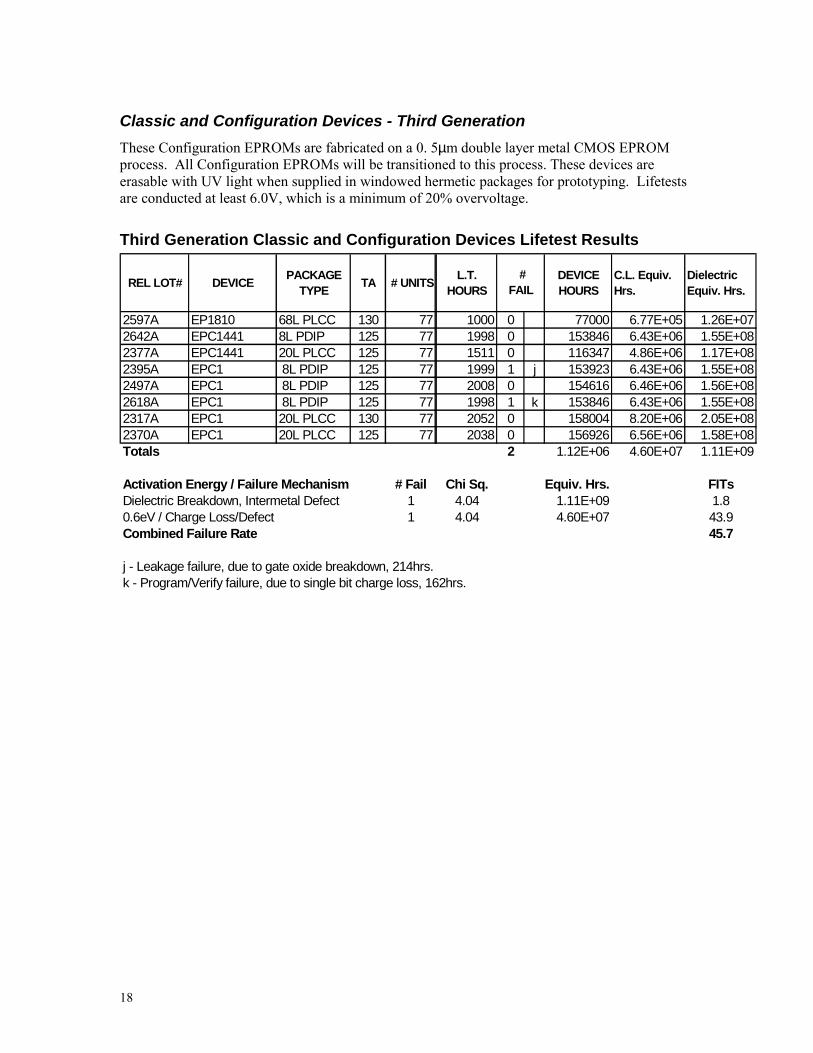
Classic and Configuration Devices - Third GenerationThese Configuration EPROMs are fabricated on a 0. 5µm double layer metal CMOS EPROMprocess. All Configuration EPROMs will be transitioned to this process. These devices areerasable with UV light when supplied in windowed hermetic packages for prototyping. Lifetestsare conducted at least 6.0V, which is a minimum of 20% overvoltage.
Third Generation Classic and Configuration Devices Lifetest Results
REL LOT# DEVICE PACKAGE TYPE TA # UNITS L.T.
HOURSDEVICE HOURS
C.L. Equiv. Hrs.
Dielectric Equiv. Hrs.
2597A EP1810 68L PLCC 130 77 1000 0 77000 6.77E+05 1.26E+072642A EPC1441 8L PDIP 125 77 1998 0 153846 6.43E+06 1.55E+082377A EPC1441 20L PLCC 125 77 1511 0 116347 4.86E+06 1.17E+082395A EPC1 8L PDIP 125 77 1999 1 j 153923 6.43E+06 1.55E+082497A EPC1 8L PDIP 125 77 2008 0 154616 6.46E+06 1.56E+082618A EPC1 8L PDIP 125 77 1998 1 k 153846 6.43E+06 1.55E+082317A EPC1 20L PLCC 130 77 2052 0 158004 8.20E+06 2.05E+082370A EPC1 20L PLCC 125 77 2038 0 156926 6.56E+06 1.58E+08Totals 2 1.12E+06 4.60E+07 1.11E+09
Activation Energy / Failure Mechanism # Fail Chi Sq. Equiv. Hrs. FITsDielectric Breakdown, Intermetal Defect 1 4.04 1.11E+09 1.80.6eV / Charge Loss/Defect 1 4.04 4.60E+07 43.9Combined Failure Rate 45.7
j - Leakage failure, due to gate oxide breakdown, 214hrs.k - Program/Verify failure, due to single bit charge loss, 162hrs.
# FAIL

19
Configuration Devices – Flash MemoryThese Configuration EPROMs are fabricated on a 0.4µ double layer metal CMOS Flash process.These devices are electrically erasable. Lifetests are conducted at least 6.0V, which is aminimum of 20% overvoltage.
Flash Memory Devices Lifetest Results
REL LOT# DEVICE PACKAGE TYPE TA #
UNITSL.T.
HOURSDEVICE HOURS
Dielectric Equiv. Hrs.
C.L. Equiv. Hrs.
2434A EPC2 20L PLCC 125 77 1999 0 153923 4.86E+07 6.43E+062550A EPC2 20L PLCC 125 77 2004 0 154308 4.87E+07 6.45E+062682A EPC2 20L PLCC 125 77 165 0 12705 4.01E+06 5.31E+05
3.21E+05 1.01E+08 1.34E+07
Activation Energy / Failure Mechanism # Fail Chi Sq. Equiv. Hrs. FITsDielectric Breakdown 0 1.83 1.01E+08 9.00.6eV / Charge Loss/Defect 1.83 1.34E+07 68.3Combined Failure Rate 77.4
This table has c=2 calculations
# FAIL

20
High Temperature StorageHigh temperature storage is performed at 150°C or greater. This stress detects bonding failuresdue to Intermetallic formation in all product families and data retention failures in non-volatilememory elements. The ability of non-volatile memory elements to retain their charge is crucialfor reliability. The leakage of charge off of the floating gate of a non-volatile configurationelement can be measured by margin test modes built into every Altera device. Charge lossmechanisms in EPROMs and EEPROMs have been well documented in the literature. iv v
High Temperature Storage Results
REL LOT# DEVICE PACKAGE
TYPEBAKETEMP. # UNITS STRESS
HOURS # FAIL Technology
2597C EP1810 68L PLCC 150 45 1000 0 0.5µ EPROM2406C EP1810 68L PLCC 125 45 1000 0 0.65µ EPROM2571C EP1810 68L PLCC 150 45 1000 0 0.65µ EPROM2354C EP910 44L PLCC 150 45 1000 0 0.65µ EPROM2615C EP910 44L PLCC 150 45 1534 0 0.65µ EPROM2395C EPC1 8L PDIP 150 45 1000 0 0.5µ EPROM2497C EPC1 8L PDIP 150 45 1000 0 0.5µ EPROM2618C EPC1 8L PDIP 150 45 1000 0 0.5µ EPROM2370C EPC1 20L PLCC 150 45 1000 0 0.5µ EPROM2414 EPC1 8L PDIP 150 21 1000 0 0.65µ EPROM2318C EPC1 20L PLCC 150 45 1000 3 l 0.65µ EPROM2385C EPC1 20L PLCC 150 45 1000 3 m 0.65µ EPROM2642C EPC1441 20L PDIP 150 45 1000 0 0.5µ EPROM2377C EPC1441 20L PLCC 150 45 1000 0 0.5µ EPROM2338C EPC1441 8L PDIP 150 45 1000 0 0.65µ EPROM2468C EPC1441 8L PDIP 150 45 1000 0 0.65µ EPROM2434C EPC2 20L PLCC 150 45 1000 0 0.4µ EPROM2550C EPC2 20L PLCC 150 45 1000 0 0.4µ EPROM2682C EPC2 20L PLCC 150 45 168 0 0.4µ EPROM2333A EPM7032AE 44L TQFP 150 45 1000 0 0.35µ EEPROM2448C EPM7032AE 44L TQFP 150 45 1000 0 0.35µ EEPROM2367C EPM7032S 44L TQFP 150 45 1000 0 0.5µ EEPROM2675C EPM7032S 44L PLCC 150 45 500 0 SHARP - CUUM2365A EPM7064AE 100L TQFP 150 45 1121 0 0.35µ EEPROM2570C EPM7064AE 44L PLCC 150 45 1000 0 0.35µ EEPROM2496C EPM7064S 100L TQFP 150 45 1096 0 0.5µ EEPROM2544C EPM7064S 44L PLCC 150 45 1000 0 0.5µ EEPROM2630C EPM7064S 44L TQFP 150 45 1000 0 0.5µ EEPROM2344C EPM7128A 100L TQFP 150 45 1000 0 0.35µ EEPROM2386C EPM7128A 144L TQFP 150 25 1000 0 0.35µ EEPROM2517C EPM7128A 144L TQFP 150 25 1000 0 0.35µ EEPROM2429A EPM7128A 84L PLCC 150 45 1000 0 0.35µ EEPROM2614C EPM7128B 144L TQFP 150 96 1034 0 0.22µ EEPROM2614D EPM7128B 144L TQFP 150 96 160 0 0.22µ EEPROM2614E EPM7128B 144L TQFP 150 69 1034 0 0.22µ EEPROM2628A EPM7128B 144L TQFP 150 69 90 0 0.22µ EEPROM

21
REL LOT# DEVICE PACKAGE
TYPEBAKETEMP. # UNITS STRESS
HOURS # FAIL Technology
2628D EPM7128B 144L TQFP 150 69 167 0 0.22µ EEPROM2363C EPM7128S 100L PQFP 150 45 1000 0 0.5µ EEPROM2617C EPM7128S 100L PQFP 150 45 1287 0 0.5µ EEPROM2553C EPM7128S 100L TQFP 150 45 1000 0 0.5µ EEPROM2334C EPM7128S 84L PLCC 150 44 1000 0 0.5µ EEPROM2371C EPM7128S 84L PLCC 150 45 1000 0 0.5µ EEPROM2437C EPM7128S 84L PLCC 150 44 1022 0 0.5µ EEPROM2470C EPM7192S 160L PQFP 150 25 1000 0 0.5µ EEPROM2664C EPM7192S 160L PQFP 150 22 1000 0 0.5µ EEPROM2478C EPM7256AE 256L BGA 150 25 1000 0 0.35µ EEPROM2349C EPM7256AE 256L FBGA 150 25 1000 0 0.35µ EEPROM2381B EPM7256AE 256L FBGA 150 25 1000 0 0.35µ EEPROM2343C EPM7256S 208L PQFP 150 25 1000 0 0.5µ EEPROM2403C EPM7256S 208L PQFP 150 25 1000 0 0.5µ EEPROM2368A EPM7512AE 144L TQFP 150 25 1000 0 0.35µ EEPROM2353B EPM7512AE 208L PQFP 150 25 1000 0 0.35µ EEPROM2402C EPM7512AE 256L BGA 150 25 1000 0 0.35µ EEPROM2430A EPM7512AE 256L BGA 150 25 1000 0 0.35µ EEPROM2654C EPM7512AE 256L BGA 150 25 1000 0 0.35µ EEPROM2439A EPM7512AE 256L FBGA 150 25 1004 0 0.35µ EEPROM2466C EPM9320A 208L RQFP 150 17 1000 0 0.5µ EEPROM2688C EPM9320A 208L RQFP 150 25 168 0 0.5µ EEPROM2356C EPM9560A 208L RQFP 150 25 1000 0 0.5µ EEPROM2465C EPM9560A 356L BGA 150 25 1000 0 0.5µ EEPROM2535C EPM9560A 356L BGA 150 24 1000 0 0.5µ EEPROM2564C EPM9560A 356L BGA 150 25 1000 0 0.5µ EEPROM
l - 3 Verify failures due to resistive or open contact, 1000hrs. Fixed on 0.5µ process.m - 3 Verify failures due to resistive or open contact, 1000hrs. Fixed on 0.5µ process.
22
Reflow Simulation and Moisture PreconditioningSurface mount devices are subject to failure due to entrapped moisture that can rapidly expandduring the reflow soldering process. vi vii Whereas dual in-line package devices are shieldedfrom the rapid heat excursion of wave soldering by the printed circuit board, surface mountdevices receive the full temperature shock of reflow soldering. Reflow soldering can beaccomplished by Vapor Phase Soldering, Infrared Reflow Soldering, or Convection ReflowSoldering. Altera recommendations for Reflow soldering are contained in Application Note 81.Reflow soldering typically has a preheat stage and then rapidly heats the device above the solderreflow temperature. Altera moisture soaks devices according to their JESD-020a moistureclassification and then passes them through simulated 100% convention reflow soldering 3 times.Altera uses a prebake cycle above 150°C for 2 minutes, a temperature ramp of 1°-3° C / second,time above 183°C of at least 1 minute, and a peak temperature of 220°C. Devices are examinedfor package cracks and electrically tested after preconditioning and reflow soldering. The devicesare then subjected to Temperature Cycle Condition B or Temperature Humidity Bias to assessreliability. The moisture preconditioning stress level is listed in the Temperature Cycling andTemperature/Humidity Bias tables for those devices that were subjected to moisturepreconditioning. The moisture classification of Altera products is imprinted on the device'smoisture barrier bag.

23
Accelerated Moisture ResistanceFour different stresses are commonly used to assess moisture resistance of integrated circuits:Temperature Humidity Bias (THB) at 85°C/85%RH, Autoclave at 121°C/100%RH, BiasedHAST at 130°C/85%RH and Unbiased HAST at 130°C/85%RH. All four stresses can detectmetallization corrosion and moisture induced charge loss in nonvolatile devices. In addition,THB and biased HAST can detect galvanic corrosion since they are biased.
AutoclaveThe Autoclave stress subjects semiconductor devices to a 121°C saturated DI water steamenvironment. At 121°C in a sealed vessel this results in a 15 PSIG pressure, or two atmospheres.The chamber used by Altera uses temperature to control the stress environment. Using pressureto control the environment as in a pressure pot results in drastic swings in temperature as steam isvented outside the chamber. The autoclave stress is designed to detect corrosion of themetallization of integrated circuits. This test can also detect charge loss in non-volatile memoryelements due to increased leakage if moisture reaches the floating gate storage element. viii
Unbiased HASTIn this stress devices are placed in a HAST chamber at 130°C/85%RH. The test does not subjectthe devices to a saturated moisture environment and no water condenses on the devices.
Autoclave & Unbiased HAST Results
REL LOT# DEVICE PACKAGE
TYPE RELIABILITY TEST #UNITS
STRESSHOURS
#FAIL Technology
2597D EP1810 68L PLCC 121°C/100% RH 45 168 0 0.5µ EPROM2406D EP1810 68L PLCC 121°C/100% RH 45 192 0 0.65µ EPROM2571F EP1810 68L PLCC 121°C/100% RH 45 168 0 0.65µ EPROM2655B EP1K100 208L PQFP 121°C/100% RH 25 168 0 0.22µ SRAM2422B EP20K100 240L PQFP 121°C/100% RH 24 168 0 0.22µ SRAM2646C EP20K100 240L PQFP 121°C/100% RH 25 168 0 0.22µ SRAM2676C EP20K100 356L BGA 130°C/85% RH 25 168 0 0.22µ SRAM2662A EP20K100E 144L TQFP 121°C/100% RH 45 168 1 n 0.18µ SRAM2663A EP20K100E 240L PQFP 121°C/100% RH 25 168 0 0.18µ SRAM2666C EP20K100E 240L PQFP 121°C/100% RH 20 168 0 0.18µ SRAM2692A EP20K100E 356L BGA 130°C/85% RH 25 96 0 0.18µ SRAM2659A EP20K100E 652L BGA 130°C/85% RH 25 168 0 0.18µ SRAM2633B EP20K200 240L RQFP 121°C/100% RH 22 168 0 0.22µ SRAM2635B EP20K400 652L BGA 130°C/85% RH 25 168 0 0.22µ SRAM2444A EP20K400 672L FBGA 121°C/100% RH 18 168 0 0.25µ SRAM2531A EP20K400 672L FBGA 121°C/100% RH 25 96 0 0.25µ SRAM2579E EP20K400E 652L BGA 130°C/85% RH 24 168 0 0.18µ SRAM2686C EP20K400E 672L FBGA 130°C/85% RH 25 168 1 o 0.18µ SRAM2627B EP20K400E 672L FCBGA 130°C/85% RH 24 168 0 0.18µ SRAM2689C EP20K400E 672L FCBGA 130°C/85% RH 24 96 0 0.18µ SRAM2354D EP910 44L PLCC 121°C/100% RH 45 168 0 0.65µ EPROM

24
REL LOT# DEVICE PACKAGE
TYPE RELIABILITY TEST #UNITS
STRESSHOURS
#FAIL Technology
2395D EPC1 8L PDIP 121°C/100% RH 45 168 0 0.5µ EPROM2497D EPC1 8L PDIP 121°C/100% RH 45 168 0 0.5µ EPROM2618D EPC1 8L PDIP 121°C/100% RH 45 168 0 0.5µ EPROM2370D EPC1 20L PLCC 121°C/100% RH 45 168 0 0.5µ EPROM2626A EPC1 20L PLCC 121°C/100% RH 45 168 0 0.5µ EPROM2385D EPC1 20L PLCC 121°C/100% RH 45 168 1 p 0.65µ EPROM2642D EPC1441 20L PDIP 121°C/100% RH 45 168 0 0.5µ EPROM2377D EPC1441 20L PLCC 121°C/100% RH 45 168 0 0.5µ EPROM2468D EPC1441 8L PDIP 121°C/100% RH 45 168 0 0.65µ EPROM2434D EPC2 20L PLCC 121°C/100% RH 45 168 0 0.4µ FLASH2550D EPC2 20L PLCC 121°C/100% RH 45 168 0 0.4µ FLASH2682D EPC2 20L PLCC 121°C/100% RH 45 168 0 0.4µ FLASH2495C EPF10K10 208L PQFP 121°C/100% RH 22 168 0 0.5µ SRAM2588B EPF10K100A 240L RQFP 121°C/100% RH 25 168 1 q 0.3µ SRAM2583D EPF10K100A 240L RQFP 121°C/100% RH 25 168 0 0.3µ SRAM2590C EPF10K100A 240L RQFP 121°C/100% RH 25 168 0 0.3µ SRAM2501C EPF10K100A 240L RQFP 121°C/100% RH 25 168 0 0.3µ SRAM2684C EPF10K100A 356L BGA 130°C/85% RH 25 168 0 0.3µ SRAM2404C EPF10K100A 356L TBGA 121°C/100% RH 25 168 0 0.3µ SRAM2522D EPF10K100A 600L BGA 121°C/100% RH 25 96 0 0.3µ SRAM2359 EPF10K100B 240L PQFP 121°C/100% RH 45 168 0 0.25µ SRAM2360 EPF10K100B 240L PQFP 121°C/100% RH 45 168 0 0.25µ SRAM2532D EPF10K100E 240L PQFP 121°C/100% RH 25 168 0 0.22µ SRAM2536D EPF10K100E 240L PQFP 121°C/100% RH 25 168 0 0.22µ SRAM2415C EPF10K100E 240L RQFP 121°C/100% RH 22 168 0 0.22µ SRAM2446C EPF10K100E 240L RQFP 121°C/100% RH 24 168 0 0.22µ SRAM2591B EPF10K100E 484L FBGA 130°C/85% RH 25 192 0 0.22µ SRAM2358 EPF10K10A 256L FBGA 121°C/100% RH 30 168 0 0.35µ SRAM2388B EPF10K130E 240L PQFP 121°C/100% RH 15 168 0 0.22µ SRAM2413B EPF10K130E 240L PQFP 121°C/100% RH 25 168 0 0.22µ SRAM2445C EPF10K130E 240L PQFP 121°C/100% RH 25 168 0 0.22µ SRAM2427B EPF10K200E 672L FBGA 121°C/100% RH 25 168 0 0.25µ SRAM2427D EPF10K200E 672L FBGA Precon 3-130°C/85% RH 25 192 0 0.25µ SRAM2681C EPF10K200S 356L BGA 130°C/85% RH 25 168 0 0.22µ SRAM2585C EPF10K200S 672L FBGA 130°C/85% RH 25 168 0 0.22µ SRAM2651A EPF10K200S 672L FBGA 130°C/85% RH 25 166 0 0.22µ SRAM2690A EPF10K200S 672L FBGA 130°C/85% RH 25 168 0 0.22µ SRAM2691A EPF10K200S 672L FBGA 130°C/85% RH 25 96 0 0.22µ SRAM2698A EPF10K200S 672L FBGA 130°C/85% RH 25 96 0 0.22µ SRAM2573D EPF10K30 240L RQFP 121°C/100% RH 25 168 0 0.42µ SRAM2631C EPF10K30 356L BGA 130°C/85% RH 25 168 0 0.42µ SRAM2398 EPF10K30 356L BGA 121°C/100% RH 45 168 0 0.5µ SRAM2524E EPF10K30A 356L BGA 130°C/85% RH 25 192 0 0.25µ SRAM2670C EPF10K30A 256L BGA 130°C/85% RH 25 168 0 0.3µ SRAM2351C EPF10K30A 484L FBGA 121°C/100% RH 25 168 0 0.35µ SRAM2346B EPF10K50 240L RQFP 121°C/100% RH 45 168 0 0.42µ SRAM

25
REL LOT# DEVICE PACKAGE
TYPE RELIABILITY TEST #UNITS
STRESSHOURS
#FAIL Technology
2361D EPF10K50 240L RQFP 121°C/100% RH 45 168 0 0.42µ SRAM2366B EPF10K50 240L RQFP 121°C/100% RH 45 168 0 0.42µ SRAM2436C EPF10K50 240L RQFP 121°C/100% RH 22 168 0 0.42µ SRAM2378C EPF10K50E 240L PQFP 121°C/100% RH 25 168 0 0.25µ SRAM2417A EPF10K50E 256L FBGA 121°C/100% RH 45 162 0 0.25µ SRAM2493A EPF10K50E 256L FBGA 121°C/100% RH 45 168 0 0.25µ SRAM2492A EPF10K50E 484L FBGA 121°C/100% RH 45 168 0 0.25µ SRAM2492B EPF10K50E 484L FBGA 130°C/85% RH 45 168 0 0.25µ SRAM2493B EPF10K50E 256L FBGA 130°C/85% RH 45 168 0 0.3µ SRAM2397C EPF10K50V 240L PQFP 121°C/100% RH 25 168 0 0.3µ SRAM2399 EPF10K50V 356L BGA 121°C/100% RH 45 168 0 0.3µ SRAM2461A EPF10K50V 356L BGA 121°C/100% RH 45 168 0 0.3µ SRAM2639C EPF10K50V 356L BGA 130°C/85% RH 25 168 0 0.3µ SRAM2640C EPF10K50V 356L BGA 130°C/85% RH 25 166 0 0.3µ SRAM2641C EPF10K50V 356L BGA 130°C/85% RH 25 168 0 0.3µ SRAM2467C EPF6016 208L PQFP 121°C/100% RH 25 168 0 0.42µ SRAM2420C EPF6016 208L PQFP 121°C/100% RH 25 192 0 0.5µ SRAM2355C EPF6016A 144L TQFP 121°C/100% RH 25 168 0 0.35µ SRAM2352A EPF6024A 144L TQFP 121°C/100% RH 45 168 0 0.3µ SRAM2350C EPF6024A 208L PQFP 121°C/100% RH 45 168 0 0.3µ SRAM2462A EPF6024A 208L PQFP 121°C/100% RH 45 168 0 0.30µ SRAM2552C EPF6024A 208L PQFP 121°C/100% RH 22 168 0 0.30µ SRAM2668C EPF81188A 240L PQFP 121°C/100% RH 25 168 0 0.42µ SRAM2569C EPF81188A 240L PQFP 121°C/100% RH 25 168 0 0.5µ SRAM2384C EPF81188A 240L RQFP 121°C/100% RH 25 168 0 0.5µ SRAM2431C EPF8282A 100L TQFP 121°C/100% RH 45 168 0 0.5µ SRAM2661C EPF8282A 100L TQFP 121°C/100% RH 45 168 0 0.5µ SRAM2530D EPF8820A 144L TQFP 121°C/100% RH 45 168 0 0.5µ SRAM2428A EPM3256A 144L TQFP 121°C/100% RH 25 168 0 0.35µ SRAM2448D EPM7032AE 44L TQFP 121°C/100% RH 45 192 0 0.35µ EEPROM2367D EPM7032S 44 TQFP 121°C/100% RH 45 168 0 0.5µ EEPROM2486A EPM7032S 44L PLCC 121°C/100% RH 45 168 0 0.5µ EEPROM2365B EPM7064AE 100L TQFP 121°C/100% RH 45 168 0 0.35µ EEPROM2570F EPM7064AE 44L PLCC 121°C/100% RH 45 168 0 0.35µ EEPROM2496D EPM7064S 100L TQFP 121°C/100% RH 45 168 0 0.5µ EEPROM2544E EPM7064S 44L PLCC 121°C/100% RH 45 168 0 0.5µ EEPROM2344D EPM7128A 100L TQFP 121°C/100% RH 45 168 0 0.35µ EEPROM2624A EPM7128A 100L TQFP 121°C/100% RH 45 168 0 0.35µ EEPROM2386D EPM7128A 144L TQFP 121°C/100% RH 25 168 0 0.35µ EEPROM2619C EPM7128AE 100L FBGA 130°C/85% RH 45 96 0 0.35µ EEPROM2475A EPM7128AE 100L FBGA 121°C/100% RH 45 168 0 0.35µ EEPROM2517D EPM7128AE 144L TQFP 121°C/100% RH 25 168 0 0.35µ EEPROM2429B EPM7128AE 84L PLCC 121°C/100% RH 45 168 0 0.35µ EEPROM2674A EPM7128B 100L FBGA 130°C/85% RH 45 168 0 0.22µ EEPROM2614G EPM7128B 144L TQFP 121°C/100% RH 25 168 0 0.22µ EEPROM2363D EPM7128S 100L PQFP 121°C/100% RH 36 168 0 0.5µ EEPROM

26
REL LOT# DEVICE PACKAGE
TYPE RELIABILITY TEST #UNITS
STRESSHOURS
#FAIL Technology
2617D EPM7128S 100L PQFP 121°C/100% RH 45 168 0 0.5µ EEPROM2371D EPM7128S 84L PLCC 121°C/100% RH 45 168 0 0.5µ EEPROM2437D EPM7128S 84L PLCC 121°C/100% RH 45 192 0 0.5µ EEPROM2470D EPM7192S 160L PQFP 121°C/100% RH 25 168 0 0.5µ EEPROM2664D EPM7192S 160L PQFP 121°C/100% RH 23 168 0 0.5µ EEPROM2349D EPM7256AE 256L FBGA 121°C/100% RH 25 168 0 0.35µ EEPROM2381C EPM7256AE 256L FBGA 121°C/100% RH 25 168 0 0.35µ EEPROM2396A EPM7256AE 256L FBGA 121°C/100% RH 25 168 0 0.35µ EEPROM2478D EPM7256AE 256L FBGA 121°C/100% RH 25 168 0 0.35µ EEPROM2584C EPM7256AE 256L FBGA 130°C/85% RH 25 168 0 0.35µ EEPROM2577E EPM7256B 208L PQFP 121°C/100% RH 25 168 0 0.22µ EEPROM2343D EPM7256S 208L PQFP 121°C/100% RH 25 168 0 0.5µ EEPROM2403D EPM7256S 208L PQFP 121°C/100% RH 25 168 0 0.5µ EEPROM2667A EPM7256S 208L RQFP 121°C/100% RH 25 168 0 0.5µ EEPROM2368B EPM7512AE 144L TQFP 121°C/100% RH 25 168 0 0.35µ EEPROM2353C EPM7512AE 208L PQFP 121°C/100% RH 25 168 0 0.35µ EEPROM2402D EPM7512AE 256L BGA 121°C/100% RH 25 163 0 0.35µ EEPROM2430B EPM7512AE 256L BGA 121°C/100% RH 25 168 0 0.35µ EEPROM2451A EPM7512AE 256L BGA 121°C/100% RH 25 168 0 0.35µ EEPROM2574B EPM7512AE 256L BGA 130°C/85% RH 25 196 0 0.35µ EEPROM2647C EPM7512AE 256L BGA 130°C/85% RH 25 168 0 0.35µ EEPROM2654D EPM7512AE 256L BGA 130°C/85% RH 25 168 0 0.35µ EEPROM2383B EPM7512AE 256L FBGA 121°C/100% RH 25 168 0 0.35µ EEPROM2439B EPM7512AE 256L FBGA 121°C/100% RH 25 168 0 0.35µ EEPROM2586F EPM7512AE 256L FBGA 130°C/85% RH 25 168 0 0.35µ EEPROM2466D EPM9320A 208L RQFP 121°C/100% RH 25 168 0 0.5µ EEPROM2356D EPM9560A 208L RQFP 121°C/100% RH 25 168 0 0.5µ EEPROM2564D EPM9560A 356L BGA 130°C/85% RH 25 168 1 r 0.5µ EEPROM2465D EPM9560A 356L BGA 121°C/100% RH 25 168 0 0.5µ EEPROM2518A EPM9560A 356L BGA 121°C/100% RH 25 168 0 0.5µ EEPROM2564G EPM9560A 356L BGA 130°C/85% RH 25 166 0 0.5µ EEPROM2644C EPM9560A 356L BGA 130°C/85% RH 25 168 0 0.5µ EEPROM2649 EPM9560A 356L BGA 130°C/85% RH 25 166 0 0.5µ EEPROM
n - Parametric failure. Failure localized on the die , non-visual defect, 96hrs.o - Opens failure. F/A in progress, 96hrs.p - Failed program/verify, due to an oxide particle in Metal 1, 168hrsq - Pin to pin short. Suspect foreign material, 96hrs.r - Opens failure, package trace open, 96hrs.

27
Temperature Humidity BiasTHB testing is commonly performed at 85°C/85%RH in order to keep condensation fromforming on the devices under test. Voltage is applied to the devices under stress, but powerconsumption is kept low or cycled on and off to keep internal power dissipation from driving offmoisture. Typical stress times are 1000 to 2000 hours, with 1000 hours used for qualification.An all stainless steel chamber and deionized (DI) water are used to insure that contamination doesnot affect the results.
The chamber is loaded, then brought up to temperature, and finally humidity is applied to insureno condensation occurs. Once the chamber reaches temperature/humidity equilibrium, voltage isapplied to the device under stress. The chamber is powered down in the following order to againinsure condensation does not occur: voltage to the device, humidity, and finally temperature.Devices are tested to datasheet parameters after 500, 1000, 1500, and 2000 hours of stress. Notall lots are carried out past 1000 hours.
Surface mount devices are subjected to moisture preconditioning and simulated 3 times throughConvention Reflow Soldering before starting the THB stress. The JEDEC level of moisturepreconditioning is listed in the table below.
Temperature Humidity Bias Results
RELLOT # DEVICE PACKAGE
TYPE RELIABILITY TEST #UNITS
STRESSHOURS
#FAIL Technology
2597F EP1810 68L PLCC PRECON 1-85/85THB 45 2000 0 0.5µ EPROM2406F EP1810 68L PLCC PRECON 1-85/85THB 45 2000 0 0.65µ EPROM2354G EP910 44L PLCC PRECON 1-85/85THB 45 2044 0 0.65µ EPROM2615G EP910 44L PLCC PRECON 1-85/85THB 45 1500 1 s 0.65µ EPROM2395F EPC1 8L PDIP PRECON 1-85/85THB 45 2000 0 0.5µ EPROM2618F EPC1 8L PDIP 85/85 - THB 45 2000 1 t 0.5µ EPROM2299E EPC1 20L PLCC PRECON 1-85/85THB 45 2000 0 0.5µ EPROM2317F EPC1 20L PLCC PRECON 1-85/85THB 45 2000 0 0.5µ EPROM2370F EPC1 20L PLCC PRECON 1-85/85THB 45 2044 0 0.5µ EPROM2626D EPC1 20L PLCC PRECON 1-85/85THB 45 2000 0 0.5µ EPROM2497F EPC1 8L PDIP 85/85 - THB 45 2042 0 0.50µ EPROM2318F EPC1 20L PLCC PRECON 1-85/85THB 45 1000 1 u 0.65µ EPROM2385F EPC1 20L PLCC PRECON 1-85/85THB 45 2042 0 0.65µ EPROM2642F EPC1441 20L PDIP 85/85 - THB 45 2000 0 0.5µ EPROM2377F EPC1441 20L PLCC PRECON 1-85/85THB 45 2000 0 0.5µ EPROM2338F EPC1441 8L PDIP 85/85 - THB 45 2000 1 v 0.65µ EPROM2468F EPC1441 8L PDIP 85/85 - THB 45 2000 0 0.65µ EPROM2339F EPC2 20L PLCC PRECON 1-85/85THB 45 2044 0 0.4µ FLASH2434F EPC2 20L PLCC PRECON 1-85/85THB 45 2000 0 0.4µ FLASH2320 EPF10K100B 256L FBGA PRECON 3-85/85THB 50 1000 3 w 0.25µ SRAM2322 EPF10K50V 356L BGA PRECON 3-85/85THB 25 2000 2 x 0.35µ SRAM2323 EPF10K50V 356L BGA PRECON 3-85/85THB 25 2000 0 0.35µ SRAM2384E EPF81188A 240L RQFP PRECON 3-85/85THB 25 2000 0 0.50µ SRAM2332H EPM7032AE 44L PLCC PRECON 3-85/85THB 40 1000 0 0.35µ EEPROM2332J EPM7032AE 44L PLCC PRECON 1-85/85THB 45 2000 0 0.35µ EEPROM

28
RELLOT # DEVICE PACKAGE
TYPE RELIABILITY TEST #UNITS
STRESSHOURS
#FAIL Technology
2274F EPM7032S 44L PLCC PRECON 2-85/85THB 45 2000 0 0.5µ EEPROM2675F EPM7032S 44L PLCC PRECON 1-85/85THB 45 500 0 0.5µ EEPROM2297D EPM7064AE 44L TQFP PRECON 3-85/85THB 40 1000 0 0.35µ EEPROM2233F EPM7064S 44L TQFP PRECON 1-85/85THB 45 2044 0 0.5µ EEPROM2429D EPM7128AE 84L PLCC PRECON 3-85/85THB 45 2000 0 0.35µ EEPROM2334F EPM7128S 84L PLCC PRECON 2-85/85THB 45 2000 0 0.5µ EEPROM2371F EPM7128S 84L PLCC PRECON 2-85/85THB 45 2044 1 y 0.5µ EEPROM2437F EPM7128S 84L PLCC PRECON 2-85/85THB 45 1000 0 0.5µ EEPROM2470F EPM7192S 160L PQFP PRECON 3-85/85THB 25 1500 0 0.5µ EEPROM2470F EPM7192S 160L PQFP PRECON 3-85/85THB 25 2000 0 0.5µ EEPROM2466F EPM9320A 208L RQFP PRECON 3-85/85THB 25 2000 0 0.5µ EEPROM2356F EPM9560A 208L RQFP PRECON 3-85/85THB 25 2000 0 0.5µ EEPROM
s - Parametric failure, possiblily due to oxide breakdown, 1000hrs.t - Program/Verify failure, due to unknown defect, 2000hrs.u - Silicon ID failure, due to open vias, 1000hrs.v - Program/Verify failure, due to open vias, 1500hrs.w - Parametric failures, due to dendritic growth between traces, 500 & 1000 hrs.-x - Opens failures, due to bond pad corrosion, 1500hrs.y - Opens failure, due to delamination of the die surface, 2044hrs.
29
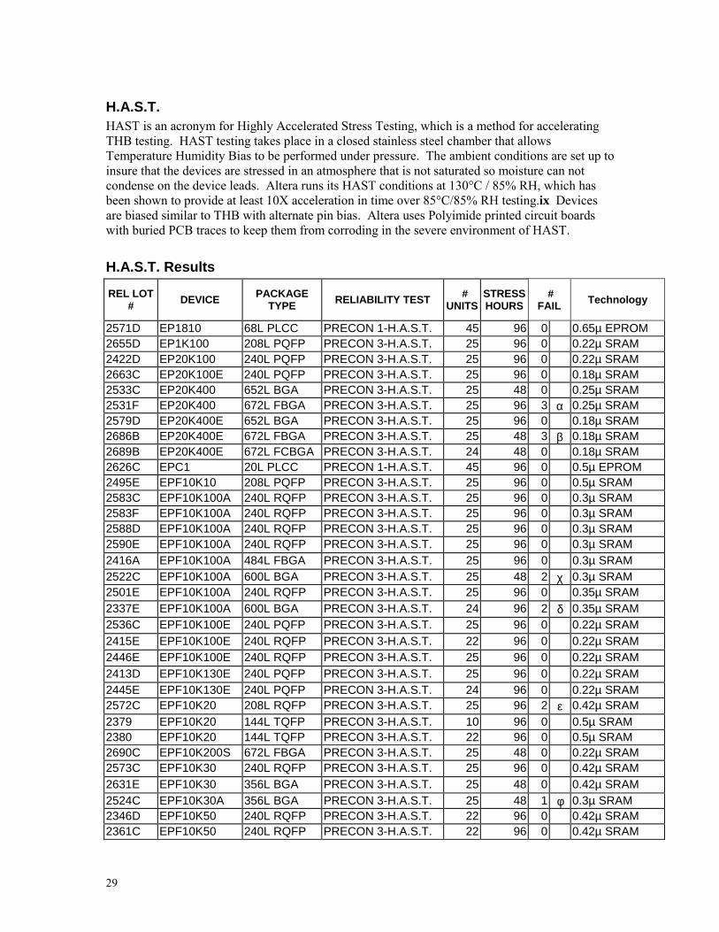
H.A.S.T.HAST is an acronym for Highly Accelerated Stress Testing, which is a method for acceleratingTHB testing. HAST testing takes place in a closed stainless steel chamber that allowsTemperature Humidity Bias to be performed under pressure. The ambient conditions are set up toinsure that the devices are stressed in an atmosphere that is not saturated so moisture can notcondense on the device leads. Altera runs its HAST conditions at 130°C / 85% RH, which hasbeen shown to provide at least 10X acceleration in time over 85°C/85% RH testing.ix Devicesare biased similar to THB with alternate pin bias. Altera uses Polyimide printed circuit boardswith buried PCB traces to keep them from corroding in the severe environment of HAST.
H.A.S.T. Results
REL LOT# DEVICE PACKAGE
TYPE RELIABILITY TEST #UNITS
STRESSHOURS
#FAIL Technology
2571D EP1810 68L PLCC PRECON 1-H.A.S.T. 45 96 0 0.65µ EPROM2655D EP1K100 208L PQFP PRECON 3-H.A.S.T. 25 96 0 0.22µ SRAM2422D EP20K100 240L PQFP PRECON 3-H.A.S.T. 25 96 0 0.22µ SRAM2663C EP20K100E 240L PQFP PRECON 3-H.A.S.T. 25 96 0 0.18µ SRAM2533C EP20K400 652L BGA PRECON 3-H.A.S.T. 25 48 0 0.25µ SRAM2531F EP20K400 672L FBGA PRECON 3-H.A.S.T. 25 96 3 α 0.25µ SRAM2579D EP20K400E 652L BGA PRECON 3-H.A.S.T. 25 96 0 0.18µ SRAM2686B EP20K400E 672L FBGA PRECON 3-H.A.S.T. 25 48 3 β 0.18µ SRAM2689B EP20K400E 672L FCBGA PRECON 3-H.A.S.T. 24 48 0 0.18µ SRAM2626C EPC1 20L PLCC PRECON 1-H.A.S.T. 45 96 0 0.5µ EPROM2495E EPF10K10 208L PQFP PRECON 3-H.A.S.T. 25 96 0 0.5µ SRAM2583C EPF10K100A 240L RQFP PRECON 3-H.A.S.T. 25 96 0 0.3µ SRAM2583F EPF10K100A 240L RQFP PRECON 3-H.A.S.T. 25 96 0 0.3µ SRAM2588D EPF10K100A 240L RQFP PRECON 3-H.A.S.T. 25 96 0 0.3µ SRAM2590E EPF10K100A 240L RQFP PRECON 3-H.A.S.T. 25 96 0 0.3µ SRAM2416A EPF10K100A 484L FBGA PRECON 3-H.A.S.T. 25 96 0 0.3µ SRAM2522C EPF10K100A 600L BGA PRECON 3-H.A.S.T. 25 48 2 χ 0.3µ SRAM2501E EPF10K100A 240L RQFP PRECON 3-H.A.S.T. 25 96 0 0.35µ SRAM2337E EPF10K100A 600L BGA PRECON 3-H.A.S.T. 24 96 2 δ 0.35µ SRAM2536C EPF10K100E 240L PQFP PRECON 3-H.A.S.T. 25 96 0 0.22µ SRAM2415E EPF10K100E 240L RQFP PRECON 3-H.A.S.T. 22 96 0 0.22µ SRAM2446E EPF10K100E 240L RQFP PRECON 3-H.A.S.T. 25 96 0 0.22µ SRAM2413D EPF10K130E 240L PQFP PRECON 3-H.A.S.T. 25 96 0 0.22µ SRAM2445E EPF10K130E 240L PQFP PRECON 3-H.A.S.T. 24 96 0 0.22µ SRAM2572C EPF10K20 208L RQFP PRECON 3-H.A.S.T. 25 96 2 ε 0.42µ SRAM2379 EPF10K20 144L TQFP PRECON 3-H.A.S.T. 10 96 0 0.5µ SRAM2380 EPF10K20 144L TQFP PRECON 3-H.A.S.T. 22 96 0 0.5µ SRAM2690C EPF10K200S 672L FBGA PRECON 3-H.A.S.T. 25 48 0 0.22µ SRAM2573C EPF10K30 240L RQFP PRECON 3-H.A.S.T. 25 96 0 0.42µ SRAM2631E EPF10K30 356L BGA PRECON 3-H.A.S.T. 25 48 0 0.42µ SRAM2524C EPF10K30A 356L BGA PRECON 3-H.A.S.T. 25 48 1 φ 0.3µ SRAM2346D EPF10K50 240L RQFP PRECON 3-H.A.S.T. 22 96 0 0.42µ SRAM2361C EPF10K50 240L RQFP PRECON 3-H.A.S.T. 22 96 0 0.42µ SRAM

30
REL LOT# DEVICE PACKAGE
TYPE RELIABILITY TEST #UNITS
STRESSHOURS
#FAIL Technology
2366D EPF10K50 240L RQFP PRECON 3-H.A.S.T. 22 96 0 0.42µ SRAM2436E EPF10K50 240L RQFP PRECON 3-H.A.S.T. 25 96 0 0.42µ SRAM2680E EPF10K50 240L RQFP PRECON 3-H.A.S.T. 25 96 0 0.42µ SRAM2336E EPF10K50 356L BGA PRECON 3-H.A.S.T. 22 96 1 γ 0.5µ SRAM2378E EPF10K50E 240L PQFP PRECON 3-H.A.S.T. 25 96 0 0.25µ SRAM2660E EPF10K50E 240L PQFP PRECON 3-H.A.S.T. 24 96 0 0.25µ SRAM2417C EPF10K50E 256L FBGA PRECON 3-H.A.S.T. 45 96 0 0.25µ SRAM2397E EPF10K50V 240L PQFP PRECON 3-H.A.S.T. 25 96 0 0.3µ SRAM2641B EPF10K50V 356L BGA PRECON 3-H.A.S.T. 25 48 0 0.3µ SRAM2190C EPF10K50V 240L RQFP PRECON 3-H.A.S.T. 22 96 0 0.35µ SRAM2325E EPF10K70 240L RQFP PRECON 3-H.A.S.T. 23 96 0 0.5µ SRAM2596E EPF10K70 240L RQFP PRECON 3-H.A.S.T. 22 96 0 0.5µ SRAM2467E EPF6016 208L PQFP PRECON 3-H.A.S.T. 25 96 0 0.42µ SRAM2420E EPF6016 208L PQFP PRECON 3-H.A.S.T. 25 96 0 0.5µ SRAM2350E EPF6024A 208L PQFP PRECON 3-H.A.S.T. 25 96 0 0.3µ SRAM2552E EPF6024A 208L PQFP PRECON 3-H.A.S.T. 23 96 0 0.3µ SRAM2222E EPF6024A 208L PQFP PRECON 3-H.A.S.T. 23 96 0 0.35µ SRAM2668E EPF81188A 240L PQFP PRECON 3-H.A.S.T. 25 96 0 0.42µ SRAM2569E EPF81188A 240L PQFP PRECON 3-H.A.S.T. 25 96 0 0.5µ SRAM2431E EPF8282A 100L TQFP PRECON 3-H.A.S.T. 45 96 0 0.5µ SRAM2661E EPF8282A 100L TQFP PRECON 3-H.A.S.T. 44 96 0 0.5µ SRAM2281E EPF8820A 144L TQFP PRECON 3-H.A.S.T. 45 94 0 0.5µ SRAM2530C EPF8820A 144L TQFP PRECON 3-H.A.S.T. 45 96 0 0.5µ SRAM2428C EPM3256A 144L TQFP PRECON 3-H.A.S.T. 25 96 0 0.35µ EEPROM2333F EPM7032AE 44L TQFP PRECON 1-H.A.S.T. 40 96 0 0.35µ EEPROM2448F EPM7032AE 44L TQFP PRECON 3-H.A.S.T. 45 96 0 0.35µ EEPROM2367F EPM7032S 44L TQFP PRECON 3-H.A.S.T. 45 96 0 0.5µ EEPROM2365D EPM7064AE 100L TQFP PRECON 3-H.A.S.T. 45 96 0 0.35µ EEPROM2657 EPM7064AE 44L PLCC PRECON 3-H.A.S.T. 45 96 0 0.35µ EEPROM2496I EPM7064S 100L TQFP PRECON 3-H.A.S.T. 45 96 0 0.5µ EEPROM2544G EPM7064S 44L PLCC PRECON 1-H.A.S.T. 45 96 0 0.5µ EEPROM2344F EPM7128A 100L TQFP PRECON 3-H.A.S.T. 45 96 0 0.35µ EEPROM2624C EPM7128A 100L TQFP PRECON 3-H.A.S.T. 45 96 0 0.35µ EEPROM2386F EPM7128A 144L TQFP PRECON 3-H.A.S.T. 25 96 0 0.35µ EEPROM2614I EPM7128B 144L TQFP PRECON 3-H.A.S.T. 25 96 0 0.22µ EEPROM2665F EPM7128B 144L TQFP PRECON 3-H.A.S.T. 25 96 0 0.22µ EEPROM2553E EPM7128S 100L TQFP PRECON 3-H.A.S.T. 45 96 0 0.5µ EEPROM2643F EPM7256A 144L TQFP PRECON 3-H.A.S.T. 25 96 0 0.35µ EEPROM2349F EPM7256A 256L FBGA PRECON 3-H.A.S.T. 25 96 0 0.35µ EEPROM2463A/C EPM7256A 256L FBGA PRECON 3-H.A.S.T. 24 96 0 0.35µ EEPROM2463B EPM7256A 256L FBGA H.A.S.T. 12 96 0 0.35µ EEPROM2464B EPM7256A 256L FBGA H.A.S.T. 12 96 0 0.35µ EEPROM2476A EPM7256A 256L FBGA PRECON 3-H.A.S.T. 11 96 0 0.35µ EEPROM2464A/C EPM7256A 256L FBGA PRECON 3-H.A.S.T. 24 96 1 η 0.35µ EEPROM2381E EPM7256A 256L FBGA PRECON 3-H.A.S.T. 25 96 1 Ι 0.35µ EEPROM2577G EPM7256B 208L PQFP PRECON 3-H.A.S.T. 25 96 0 0.22µ EEPROM
31
REL LOT# DEVICE PACKAGE
TYPE RELIABILITY TEST #UNITS
STRESSHOURS
#FAIL Technology
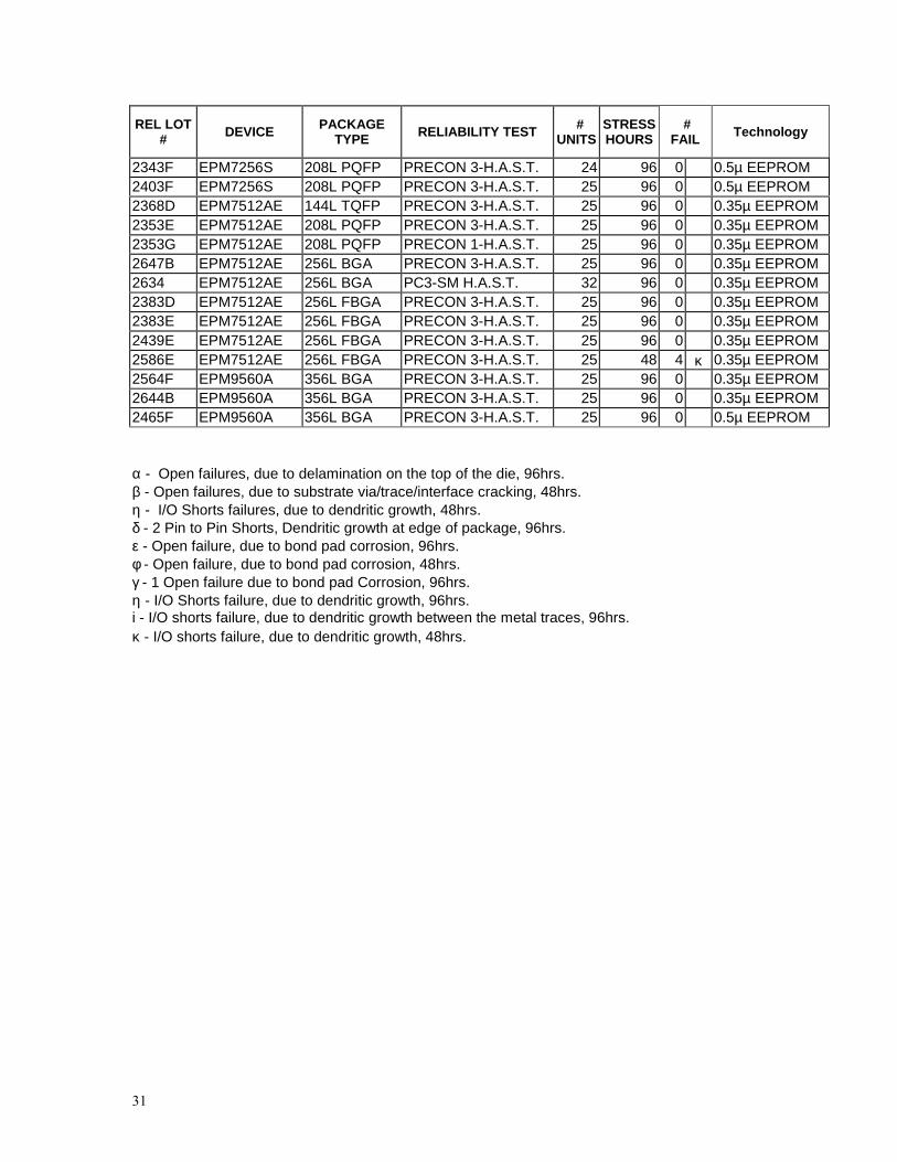
2343F EPM7256S 208L PQFP PRECON 3-H.A.S.T. 24 96 0 0.5µ EEPROM2403F EPM7256S 208L PQFP PRECON 3-H.A.S.T. 25 96 0 0.5µ EEPROM2368D EPM7512AE 144L TQFP PRECON 3-H.A.S.T. 25 96 0 0.35µ EEPROM2353E EPM7512AE 208L PQFP PRECON 3-H.A.S.T. 25 96 0 0.35µ EEPROM2353G EPM7512AE 208L PQFP PRECON 1-H.A.S.T. 25 96 0 0.35µ EEPROM2647B EPM7512AE 256L BGA PRECON 3-H.A.S.T. 25 96 0 0.35µ EEPROM2634 EPM7512AE 256L BGA PC3-SM H.A.S.T. 32 96 0 0.35µ EEPROM2383D EPM7512AE 256L FBGA PRECON 3-H.A.S.T. 25 96 0 0.35µ EEPROM2383E EPM7512AE 256L FBGA PRECON 3-H.A.S.T. 25 96 0 0.35µ EEPROM2439E EPM7512AE 256L FBGA PRECON 3-H.A.S.T. 25 96 0 0.35µ EEPROM2586E EPM7512AE 256L FBGA PRECON 3-H.A.S.T. 25 48 4 κ 0.35µ EEPROM2564F EPM9560A 356L BGA PRECON 3-H.A.S.T. 25 96 0 0.35µ EEPROM2644B EPM9560A 356L BGA PRECON 3-H.A.S.T. 25 96 0 0.35µ EEPROM2465F EPM9560A 356L BGA PRECON 3-H.A.S.T. 25 96 0 0.5µ EEPROM
α - Open failures, due to delamination on the top of the die, 96hrs.β - Open failures, due to substrate via/trace/interface cracking, 48hrs.η - I/O Shorts failures, due to dendritic growth, 48hrs.δ - 2 Pin to Pin Shorts, Dendritic growth at edge of package, 96hrs.ε - Open failure, due to bond pad corrosion, 96hrs.φ - Open failure, due to bond pad corrosion, 48hrs.γ - 1 Open failure due to bond pad Corrosion, 96hrs.η - I/O Shorts failure, due to dendritic growth, 96hrs.i - I/O shorts failure, due to dendritic growth between the metal traces, 96hrs.κ - I/O shorts failure, due to dendritic growth, 48hrs.

32
Temperature CyclingTemperature cycling accelerates the effects of changes in temperature on integrated circuits.Changes in temperature cause the different materials used in an integrated circuit to expand andcontract at different rates since they have different coefficients of expansion. Coefficients ofexpansion vary from 17 x 10-6mm/mm/°C for many molding compounds and AlCu leadframes to4.2 for Silicon and Alloy 42 leadframes. The temperature extremes in temperature cycling giverise to mechanical stresses from the difference in thermal coefficients of expansion.x The stressis greatest for large die and large packages. Thin film cracking and sheared ball bonds are theprimary failure mechanisms observed in temperature cycling.
Altera uses dual chamber temperature cycling machines. The top chamber is maintained at thehigh temperature and the bottom chamber is maintained at the low temperature. The devicesunder stress are placed in an elevator platform that transfers the devices between the twochambers. The devices are transferred between chambers in a few seconds and reach the chambertemperature within 5 minutes, and are maintained at that temperature for a minimum of 5minutes. Altera uses three of the MIL Std. 883 conditions for temperature cycling; condition K(0°C to +125°C), condition B (-55°C to +125°C), and condition C (-65°C to +150°C). The -65°Cto +150°C condition is primarily used for hermetic packages, the -55°C 10 +125°C condition isused for plastic packages and some devices with very large die size are tested to the 0°C to+125°C condition. Devices are tested after 500 and 1000 cycles. Devices, which have beenmoisture preconditioned, are listed by the JEDEC moisture level.
Temperature Cycling Results
RELLOT # DEVICE PACKAGE
TYPE RELIABILITY TEST #UNITS
# OFCYCLES
#FAIL Technology
2597E EP1810 68L PLCC PRECON1-TEMP CYC B 45 1100 0 0.5µ EPROM2406E EP1810 68L PLCC PRECON3-TEMP CYC B 45 1000 0 0.65µ EPROM2571E EP1810 68L PLCC PRECON3-TEMP CYC C 45 500 0 0.65µ EPROM2669B EP1810 68L PLCC PRECON2-TEMP CYC B 45 1000 0 0.65µ EPROM2655C EP1K100 208L PQFP PRECON3-TEMP CYC B 25 1000 0 0.22µ SRAM2422C EP20K100 240L PQFP PRECON3-TEMP CYC B 25 1000 0 0.22µ SRAM2646D EP20K100 240L PQFP PRECON3-TEMP CYC B 25 500 0 0.22µ SRAM2679 EP20K1000E 652L BGA PRECON3-TEMP CYC K 25 500 0 0.18µ SRAM2662B EP20K100E 144L TQFP PRECON3-TEMP CYC B 45 500 0 0.18µ SRAM2663B EP20K100E 240L PQFP PRECON3-TEMP CYC B 25 1000 0 0.18µ SRAM2633C EP20K200 240L RQFP PRECON3-TEMP CYC B 22 1000 0 0.22µ SRAM2692B EP20K200E 356L BGA PRECON3-TEMP CYC B 25 100 0 0.18µ SRAM2659B EP20K200E 652L BGA PRECON3-TEMP CYC B 25 500 0 0.18µ SRAM2421B EP20K400 652L BGA PRECON3-TEMP CYC B 25 1500 0 0.25µ SRAM2533B EP20K400 652L BGA PRECON3-TEMP CYC B 25 1000 0 0.25µ SRAM2531B EP20K400 672L FBGA PRECON3-TEMP CYC K 25 1000 0 0.25µ SRAM2587 EP20K400 672L FBGA PRECON3-TEMP CYC K 22 2000 0 0.25µ SRAM2579C EP20K400E 652L BGA PRECON3-TEMP CYC B 25 1000 0 0.18µ SRAM2582B EP20K400E 652L BGA PRECON3-TEMP CYC B 25 1000 1 λ 0.18µ SRAM2648A EP20K400E 652L BGA PRECON3-TEMP CYC B 25 1000 0 0.18µ SRAM2686A EP20K400E 672L FCBGA PRECON3-TEMP CYC B 25 100 0 0.18µ SRAM

33
RELLOT # DEVICE PACKAGE
TYPE RELIABILITY TEST #UNITS
# OFCYCLES
#FAIL Technology
2689A EP20K400E 672L FCBGA PRECON3-TEMP CYC B 24 100 0 0.18µ SRAM2354E EP910 44L PLCC PRECON1-TEMP CYC B 45 1000 0 0.65µ EPROM2395E EPC1 8L PDIP PRECON1-TEMP CYC B 45 1000 0 0.5µ EPROM2497E EPC1 8L PDIP TEMPERATURE CYCLE B 45 1000 0 0.5µ EPROM2618E EPC1 8L PDIP TEMPERATURE CYCLE B 45 1000 0 0.5µ EPROM2370E EPC1 20L PLCC PRECON1-TEMP CYC B 45 1000 0 0.5µ EPROM2385E EPC1 20L PLCC PRECON1-TEMP CYC B 45 1000 0 0.5µ EPROM2626B EPC1 20L PLCC PRECON1-TEMP CYC B 45 1000 0 0.5µ EPROM2658A EPC1 20L PLCC PRECON1-TEMP CYC B 45 1000 0 0.5µ EPROM2658B EPC1 20L PLCC PRECON2-TEMP CYC B 45 1000 0 0.5µ EPROM2658C EPC1 20L PLCC PRECON3-TEMP CYC B 45 1000 0 0.5µ EPROM2642E EPC1441 20L PDIP TEMPERATURE CYCLE B 45 1024 0 0.5µ EPROM2377E EPC1441 20L PLCC PRECON1-TEMP CYC B 45 1000 0 0.5µ EPROM2338E EPC1441 8L PDIP TEMPERATURE CYCLE B 45 1000 0 0.65µ EPROM2468E EPC1441 8L PDIP TEMPERATURE CYCLE B 45 1000 0 0.65µ EPROM2339E EPC2 20L PLCC PRECON1-TEMP CYC B 45 1000 0 0.4µ FLASH2434E EPC2 20L PLCC PRECON1-TEMP CYC B 45 1000 0 0.4µ FLASH2550E EPC2 20L PLCC PRECON1-TEMP CYC B 45 1000 0 0.4µ FLASH2656A EPC2 20L PLCC PRECON1-TEMP CYC B 45 1000 0 0.4µ FLASH2656B EPC2 20L PLCC PRECON2-TEMP CYC B 45 1000 0 0.4µ FLASH2656C EPC2 20L PLCC PRECON3-TEMP CYC B 45 1000 0 0.4µ FLASH2495D EPF10K10 208L PQFP PRECON3-TEMP CYC C 22 500 0 0.5µ SRAM2262C EPF10K100 503L PGA TEMPERATURE CYCLE C 22 1000 1 µ 0.5µ SRAM2501D EPF10K100A 240L RQFP PRECON3-TEMP CYC B 25 1000 0 0.3µ SRAM2583B EPF10K100A 240L RQFP PRECON3-TEMP CYC B 25 1000 0 0.3µ SRAM2583E EPF10K100A 240L RQFP PRECON3-TEMP CYC B 25 1000 0 0.3µ SRAM2588C EPF10K100A 240L RQFP PRECON3-TEMP CYC B 25 1000 0 0.3µ SRAM2590D EPF10K100A 240L RQFP PRECON3-TEMP CYC B 25 1000 0 0.3µ SRAM2404D EPF10K100A 356L BGA PRECON3-TEMP CYC B 25 1000 0 0.3µ SRAM2684A EPF10K100A 356L BGA PRECON3-TEMP CYC B 25 100 0 0.3µ SRAM2522B EPF10K100A 600L BGA PRECON3-TEMP CYC B 25 1000 0 0.3µ SRAM2337D EPF10K100A 600L BGA PRECON3-TEMP CYC B 25 1000 0 0.35µ SRAM2532B EPF10K100E 240L PQFP PRECON3-TEMP CYC B 25 1000 0 0.22µ SRAM2536B EPF10K100E 240L PQFP PRECON3-TEMP CYC B 25 1000 0 0.22µ SRAM2415D EPF10K100E 240L RQFP PRECON3-TEMP CYC B 22 1000 0 0.22µ SRAM2446D EPF10K100E 240L RQFP PRECON3-TEMP CYC B 25 1000 0 0.22µ SRAM2591E EPF10K100E 484L FBGA PRECON5-TEMP CYC B 25 1000 0 0.22µ SRAM2388C EPF10K130E 240L PQFP PRECON3-TEMP CYC B 16 1000 0 0.22µ SRAM2413C EPF10K130E 240L PQFP PRECON3-TEMP CYC B 25 1000 0 0.22µ SRAM2445D EPF10K130E 240L PQFP PRECON3-TEMP CYC B 25 1000 0 0.22µ SRAM2534 EPF10K130E 484L FBGA TEMPERATURE CYCLE B 25 100 0 0.22µ SRAM2523B EPF10K130E 600L BGA PRECON3-TEMP CYC B 25 1000 0 0.22µ SRAM2330 EPF10K200E 600L BGA PRECON3-TEMP CYC B 31 1500 0 0.25µ SRAM2427C EPF10K200E 672L FBGA PRECON3-TEMP CYC B 25 1000 0 0.25µ SRAM2539B EPF10K200S 240L RQFP PRECON3-TEMP CYC B 25 500 0 0.22µ SRAM2539B EPF10K200S 240L RQFP PRECON3-TEMP CYC B 25 1000 0 0.22µ SRAM

34
RELLOT # DEVICE PACKAGE
TYPE RELIABILITY TEST #UNITS
# OFCYCLES
#FAIL Technology
2681A EPF10K200S 356L BGA PRECON3-TEMP CYC B 25 100 0 0.22µ SRAM2585A EPF10K200S 672L FBGA PRECON3-TEMP CYC B 25 1000 0 0.22µ SRAM2651B EPF10K200S 672L FBGA PRECON3-TEMP CYC B 25 1000 0 0.22µ SRAM2690B EPF10K200S 672L FBGA PRECON3-TEMP CYC B 25 100 0 0.22µ SRAM2691B EPF10K200S 672L FBGA PRECON3-TEMP CYC B 25 100 0 0.22µ SRAM2573B EPF10K30 240L RQFP PRECON3-TEMP CYC B 25 1000 0 0.42µ SRAM2670D EPF10K30A 256L BGA PRECON5-TEMP CYC B 25 500 0 0.3µ SRAM2524B EPF10K30A 356L BGA PRECON3-TEMP CYC B 25 1000 0 0.3µ SRAM2351D EPF10K30A 484L FBGA PRECON3-TEMP CYC B 25 1000 0 0.35µ SRAM2346C EPF10K50 240L RQFP PRECON3-TEMP CYC B 45 1000 0 0.42µ SRAM2361B EPF10K50 240L RQFP PRECON3-TEMP CYC B 45 1000 0 0.42µ SRAM2366C EPF10K50 240L RQFP PRECON3-TEMP CYC B 45 1000 0 0.42µ SRAM2378D EPF10K50E 240L PQFP PRECON3-TEMP CYC B 25 1000 0 0.25µ SRAM2397D EPF10K50V 240L PQFP PRECON3-TEMP CYC B 25 1000 0 0.3µ SRAM2560B EPF10K50V 240L PQFP PRECON3-TEMP CYC B 50 1000 0 0.3µ SRAM2639D EPF10K50V 356L BGA PRECON3-TEMP CYC B 25 1024 0 0.3µ SRAM2640D EPF10K50V 356L BGA PRECON3-TEMP CYC B 25 1024 0 0.3µ SRAM2461C EPF10K50V 356L BGA PRECON3-TEMP CYC B 45 1000 0 0.3µ SRAM2641A EPF10K50V 356L BGA PRECON3-TEMP CYC B 25 1000 0 0.3µ SRAM2376A EPF10K50V 484L FBGA PRECON3-TEMP CYC B 25 1000 0 0.3µ SRAM2325D EPF10K70 240L RQFP PRECON3-TEMP CYC B 22 1000 0 0.5µ SRAM2467D EPF6016 208L PQFP PRECON3-TEMP CYC B 25 1000 0 0.42µ SRAM2420D EPF6016 208L PQFP PRECON3-TEMP CYC B 25 1000 0 0.5µ SRAM2355D EPF6016A 144L TQFP PRECON3-TEMP CYC B 25 1000 0 0.35µ SRAM2352B EPF6024A 144L TQFP PRECON3-TEMP CYC B 45 1000 0 0.3µ SRAM2350D EPF6024A 208L PQFP PRECON3-TEMP CYC B 45 1000 0 0.3µ SRAM2462B EPF6024A 208L PQFP PRECON3-TEMP CYC B 45 1000 0 0.3µ SRAM2552D EPF6024A 208L PQFP PRECON3-TEMP CYC B 22 1000 0 0.3µ SRAM2668D EPF81188A 240L PQFP PRECON3-TEMP CYC B 25 1000 0 0.42µ SRAM2569D EPF81188A 240L PQFP PRECON3-TEMP CYC B 25 1000 0 0.5µ SRAM2384D EPF81188A 240L RQFP PRECON3-TEMP CYC B 25 1000 0 0.5µ SRAM2431D EPF8282A 100L TQFP PRECON3-TEMP CYC B 45 1000 0 0.5µ SRAM2661D EPF8282A 100L TQFP PRECON3-TEMP CYC B 45 1000 0 0.5µ SRAM2530B EPF8820A 144L TQFP PRECON3-TEMP CYC B 45 1000 0 0.5µ SRAM2428B EPM3256A 144L TQFP PRECON3-TEMP CYC B 25 1000 0 0.35µ EEPROM2332I EPM7032AE 44L PLCC PRECON1-TEMP CYC B 45 1000 0 0.35µ EEPROM2333E EPM7032AE 44L TQFP PRECON1-TEMP CYC B 45 1000 0 0.35µ EEPROM2448E EPM7032AE 44L TQFP PRECON3-TEMP CYC B 45 1000 0 0.35µ EEPROM2557 EPM7032AE 44L TQFP PRECON3-TEMP CYC B 45 1000 0 0.35µ EEPROM2367E EPM7032S 44L TQFP PRECON3-TEMP CYC B 45 500 0 0.5µ EEPROM2365C EPM7064AE 100L TQFP PRECON3-TEMP CYC B 45 1000 0 0.35µ EEPROM2559 EPM7064AE 100L TQFP PRECON3-TEMP CYC B 45 1000 0 0.35µ EEPROM2570E EPM7064AE 44L PLCC PRECON3-TEMP CYC C 45 500 0 0.35µ EEPROM2558 EPM7064AE 44L TQFP PRECON3-TEMP CYC B 45 1000 0 0.35µ EEPROM2496H EPM7064S 100L TQFP PRECON3-TEMP CYC B 45 1000 0 0.5µ EEPROM2544F EPM7064S 44L PLCC PRECON1-TEMP CYC B 45 1000 0 0.5µ EEPROM2344E EPM7128A 100L TQFP PRECON3-TEMP CYC B 45 1000 0 0.35µ EEPROM

35
RELLOT # DEVICE PACKAGE
TYPE RELIABILITY TEST #UNITS
# OFCYCLES
#FAIL Technology
2624B EPM7128A 100L TQFP PRECON3-TEMP CYC B 45 1000 0 0.35µ EEPROM2556 EPM7128A 100L TQFP PRECON3-TEMP CYC B 45 1000 0 0.35µ EEPROM2386E EPM7128A 144L TQFP PRECON3-TEMP CYC B 25 1000 0 0.35µ EEPROM2555 EPM7128A 144L TQFP PRECON3-TEMP CYC B 25 1000 0 0.35µ EEPROM2506 EPM7128A 84L PLCC PRECON3-TEMP CYC B 45 1000 0 0.35µ EEPROM2619A EPM7128AE 100L FBGA PRECON3-TEMP CYC B 45 1100 0 0.35µ EEPROM2517E EPM7128AE 144L TQFP PRECON3-TEMP CYC B 25 1000 0 0.35µ EEPROM2487 EPM7128AE 84L PLCC PRECON3-TEMP CYC B 45 1000 0 0.35µ EEPROM2429C EPM7128AE 84L PLCC PRECON3-TEMP CYC B 45 1000 2 ν 0.35µ EEPROM2674B EPM7128B 100L FBGA PRECON3-TEMP CYC B 45 500 0 0.22µ EEPROM2614H EPM7128B 144L TQFP PRECON3-TEMP CYC B 25 1000 0 0.22µ EEPROM2665E EPM7128B 144L TQFP PRECON3-TEMP CYC B 25 1000 0 0.22µ EEPROM2363E EPM7128S 100L PQFP PRECON3-TEMP CYC B 45 1000 0 0.5µ EEPROM2617E EPM7128S 100L PQFP PRECON3-TEMP CYC B 45 1000 0 0.5µ EEPROM2553D EPM7128S 100L TQFP PRECON3-TEMP CYC B 45 1000 0 0.5µ EEPROM2371E EPM7128S 84L PLCC PRECON2-TEMP CYC B 45 1000 0 0.5µ EEPROM2437E EPM7128S 84L PLCC PRECON3-TEMP CYC B 45 1000 0 0.5µ EEPROM2664E EPM7192S 160L PQFP PRECON3-TEMP CYC B 25 1000 0 0.5µ EEPROM2568A EPM7256A 144L TQFP PRECON3-TEMP CYC B 25 1000 0 0.35µ EEPROM2568B EPM7256A 144L TQFP PRECON3-TEMP CYC B 25 1000 0 0.35µ EEPROM2349E EPM7256A 256L FBGA PRECON3-TEMP CYC B 25 1000 0 0.35µ EEPROM2381D EPM7256A 256L FBGA PRECON3-TEMP CYC B 25 1000 0 0.35µ EEPROM2396B EPM7256A 256L FBGA PRECON3-TEMP CYC B 25 1000 0 0.35µ EEPROM2643E EPM7256AE 144L TQFP PRECON3-TEMP CYC B 25 1000 0 0.35µ EEPROM2478E EPM7256AE 256L BGA PRECON3-TEMP CYC B 25 1000 0 0.35µ EEPROM2584A EPM7256AE 256L FBGA PRECON3-TEMP CYC B 25 1000 0 0.35µ EEPROM2577F EPM7256B 208L PQFP PRECON3-TEMP CYC B 25 1000 0 0.22µ EEPROM2343E EPM7256S 208L PQFP PRECON3-TEMP CYC B 24 1000 0 0.5µ EEPROM2403E EPM7256S 208L PQFP PRECON3-TEMP CYC B 25 1000 0 0.5µ EEPROM2368C EPM7512A 144L TQFP PRECON3-TEMP CYC B 25 1000 0 0.35µ EEPROM2353D EPM7512A 208L PQFP PRECON3-TEMP CYC B 25 1000 0 0.35µ EEPROM2353F EPM7512A 208L PQFP PRECON1-TEMP CYC B 25 1000 0 0.35µ EEPROM2369 EPM7512A 208L PQFP PRECON3-TEMP CYC B 25 1000 0 0.35µ EEPROM2412 EPM7512A 256L BGA PRECON5-TEMP CYC B 25 1000 0 0.35µ EEPROM2430C EPM7512A 256L BGA PRECON3-TEMP CYC B 25 1000 0 0.35µ EEPROM2433 EPM7512A 256L BGA PRECON5-TEMP CYC B 25 1000 0 0.35µ EEPROM2451B EPM7512A 256L BGA PRECON3-TEMP CYC B 25 1000 0 0.35µ EEPROM2328 EPM7512A 256L BGA PRECON3-TEMP CYC B 34 2000 1 ο 0.35µ EEPROM2383C EPM7512A 256L FBGA PRECON3-TEMP CYC B 25 1000 0 0.35µ EEPROM2439C EPM7512A 256L FBGA PRECON3-TEMP CYC B 25 1000 0 0.35µ EEPROM2442 EPM7512A 256L FBGA TEMPERATURE CYCLE B 600 100 0 0.35µ EEPROM2574C EPM7512AE 256L BGA PRECON3-TEMP CYC B 25 1000 0 0.35µ EEPROM2654E EPM7512AE 256L BGA PRECON3-TEMP CYC B 25 1000 0 0.35µ EEPROM2586D EPM7512AE 256L FBGA PRECON3-TEMP CYC B 25 1000 0 0.35µ EEPROM2466E EPM9320A 208L RQFP PRECON3-TEMP CYC B 25 1000 0 0.5µ EEPROM2470E EPM9320A 208L RQFP PRECON3-TEMP CYC B 25 1000 0 0.5µ EEPROM2261D EPM9560 280L PGA TEMPERATURE CYCLE C 22 1000 0 0.65µ EEPROM2356E EPM9560A 208L RQFP PRECON3-TEMP CYC B 25 1000 0 0.5µ EEPROM2465E EPM9560A 356L BGA PRECON3-TEMP CYC B 25 1000 0 0.5µ EEPROM

36
RELLOT # DEVICE PACKAGE
TYPE RELIABILITY TEST #UNITS
# OFCYCLES
#FAIL Technology
2474 EPM9560A 356L BGA TEMPERATURE CYCLE B 24 1000 0 0.5µ EEPROM2484A EPM9560A 356L BGA TEMPERATURE CYCLE B 24 1000 0 0.5µ EEPROM2484B EPM9560A 356L BGA TEMPERATURE CYCLE B 24 1000 0 0.5µ EEPROM2505 EPM9560A 356L BGA PRECON3-TEMP CYC B 48 1000 0 0.5µ EEPROM2529A EPM9560A 356L BGA PRECON3-TEMP CYC B 25 1000 0 0.5µ EEPROM2545 EPM9560A 356L BGA PRECON3-TEMP CYC B 24 1000 0 0.5µ EEPROM2564E EPM9560A 356L BGA PRECON3-TEMP CYC B 25 1000 0 0.5µ EEPROM2644A EPM9560A 356L BGA PRECON3-TEMP CYC B 25 1000 0 0.5µ EEPROM2671 EPM9560A 356L BGA TEMPERATURE CYCLE B 27 100 0 0.5µ EEPROM
λ - Functional failure, due to thin film cracking, 500 cycles.µ - 1pc failed for Opens.FA in progressν - I/O Shorts failures, due to die crack , 100 & 500 cycles.ο - 1 Open Failure due to bond wire broken by package crack, 500 cycles.

37
Latch-up
CMOS integrated circuits employ both NMOS and PMOS transistors built on the same substrate.Parasitic NPN and PNP bipolar transistors are created by the use of CMOS technology. Thesetransistors can be modeled as a Silicon Controlled Rectifier between the Vcc and Gnd powersupplies. If the gain of the SCR is greater than unity and a large enough trigger current isgenerated, latchup can occur causing either temporary malfunction or permanent damage.Trigger currents are typically generated by power supply spikes or by noise currents injected intosignal pins.
Altera tests the resistance of its devices to Latchup based upon JEDEC standard No. 17 entitledLatchup Testing of CMOS Integrated Circuits or JEDEC standard No. 78 entitled IC LatchupTest. Latchup resistance is tested using the Post Vcc stress method. First power is supplied tothe device at nominal Vcc and Icc is measured, then Vcc is increased to the test voltage, andfinally the trigger current is applied one pin at a time in 20-30mA increments. The device is thenreturned to the nominal Vcc condition and Icc is compared to nominal to see if the device latchedup. The trigger current that caused the latch up is then recorded. The device is tested for triggercurrents to all signal pins for both positive and negative trigger currents. The voltage on thesignal pin is tested to the maximum voltage listed in the table of Latchup Test Results. The Vccmaximum overvoltage test results are also listed in the table of Latchup Test Results.
JEDEC standard 78 was issued in March of 1997 and all new devices are characterized to thisnew standard, and they are denoted by a #. There are a number of differences between the twostandards, but the main three are listed in the Table below.
JEDEC 17 vs. 78
Test Description JEDEC 17 JEDEC 78Test Temperature 125°C 25°C and 125°CUnused Input Pins Vss or Vcc Test at both Vilmin and VihmaxCurrent Injection Clamp Voltage Vcc 150% of Vcc

38
Latch-up Test Results @ 125°°°°C
Product Passing NegativeTrigger Current
Passing TriggerCurrent, 90% of
pinsMax. + I\O Clamping
Voltage (V)Max. Vcc Over-
Voltage (V)
EP1810 0.5µ -135.00 135.00 8.7 > 9.0EP1810 0.65µ # -300mA 300mA 8.7 8.7EP1K10 0.22µ -300mA 300mA 5.0 >5.0EP20K200 0.22µ -300mA 300mA 8.7 > 6.0EP20K400 0.22µ -300mA 300mA 8.7 > 6.0EP20K400E 0.18µ -150mA 150mA 5.4 4.0EP610 0.65µ -300mA 300mA 7.0 8.7EP910 0.65µ -300mA 300mA 7.0 8.7EPC1 0.5µ # -300mA 300mA 8.7 8.7EPC1 0.65µ -300mA 300mA 7.0 10.0EPC1441 0.5µ # -300mA 300mA 7.0 10.0EPC2 0.4µ # -300mA 300mA 8.7 9.0EPF10K10 0.42µ * # -300mA 300mA 8.7 8.5EPF10K10 0.5µ -300mA 300mA 7.0 9.0EPF10K100 0.5µ -300mA 300mA 7.0 10.0EPF10K100A 0.3µ # -300mA 300mA 7.0 >6.0EPF10K100A 0.35µ * # -300mA 300mA 7.0 6.1EPF10K100B 0.25µ # -300mA 300mA 8.0 6.0EPF10K100E 0.22µ # -300mA 300mA 7.0 7.0EPF10K10A 0.35µ * # -300mA 300mA 7.0 6.9EPF10K130E 0.22µ # -300mA 300mA 7.0 5.5EPF10K130V 0.35µ * # -300mA 300mA 7.0 6.1EPF10K20 0.5µ -300mA 300mA 7.0 9.7EPF10K200S 0.22µ -300mA 300mA 7.0 >7.0EPF10K250A 0.35µ -300mA 300mA 7.0 6.7EPF10K30 0.5µ -300mA 300mA 7.0 9.2EPF10K30A 0.3µ # -300mA 300mA 7.0 6.8EPF10K40 0.5µ -300mA 300mA 7.0 9.7EPF10K50 0.42µ # -300mA 300mA 8.6 10.0EPF10K50 0.5µ -300mA 300mA 7.0 10.0EPF10K50E 0.25µ -300mA 300mA 7.0 7.0EPF10K50S 0.22µ -300mA 300mA 7.0 >7.0EPF10K50V 0.3µ # -300mA 300mA 7.0 7.0EPF10K50V 0.35µ * # -300mA 300mA 7.0 6.2EPF10K70 0.5µ -300mA 300mA 7.0 9.6EPF6016 0.5µ # -300mA 300mA 8.7 8.9EPF6016A 0.35µ * # -300mA 300mA 7.0 7.0EPF6024A 0.3µ # -300mA 300mA 7.0 7.0EPF6024A 0.35µ * # -300mA 300mA 7.0 6.2EPF81188A 0.42µ -300mA 300mA 8.7 > 9.0EPF81188A 0.5µ -300mA 300mA 7.0 9.5EPF81188A 0.6µ -300mA 300mA 7.0 8.7EPF81500A 0.5µ -300mA 300mA 7.0 9.2EPF8282AV 0.5µ * -300mA 300mA 7.0 9.0EPF8452A 0.6µ -300mA 300mA 7.0 10.0EPF8636A 0.6µ -300mA 300mA 7.0 8.7EPM7032 0.65µ -300mA 300mA 7.0 9.0EPM7032AE 0.35u # -180mA 300mA 8.7 6.4

39
Product Passing NegativeTrigger Current
Passing TriggerCurrent, 90% of
pinsMax. + I\O Clamping
Voltage (V)Max. Vcc Over-
Voltage (V)
EPM7032B 0.22µ -300mA 300mA 5.0 4.05EPM7032S 0.5µ # -300mA 300mA 8.7 9.0EPM7064AE 0.35u # -300mA 300mA 7.0 > 9.0EPM7064S 0.5µ # -300mA 300mA 8.7 >9.0EPM7128A 0.35µ # -230mA 230mA 8.0 9.0EPM7128AE 0.35u # -230mA 230mA 8.0 8.5EPM7128B 0.22µ -300mA 300mA 5.0 4.05EPM7128E 0.65µ -300mA 300mA 7.0 9.0EPM7128S 0.5µ # -300mA 300mA 8.7 8.5EPM7160S 0.5µ # -300mA 300mA 8.7 8.5EPM7192S 0.5µ -300mA 300mA 7.0 8.9EPM7256A 0.35µ # -300mA 300mA 8.0 8.8EPM7256AE 0.35u # -300mA 300mA 8.0 7.9EPM7256B 0.22µ -300mA 300mA 5.0 4.05EPM7256S 0.5µ -300mA 300mA 8.7 9.0EPM7512AE 0.35µ # -300mA 300mA 8.0 7.3EPM7512B 0.22µ -300mA 300mA 5.0 4.05EPM9320A 0.5µ # -300mA 300mA 8.7 8.6EPM9560 0.65µ -300mA 300mA 7.0 9.0EPM9560A 0.5µ # -300mA 300mA 8.7 >9
* 3.3V Power Supply# JEDEC 78 Test method
40
Electrostatic DischargeSemiconductor devices are vulnerable to damage by electrostatic discharge. There are manypotential damage mechanisms such as rupture of oxides, p-n junction breakdown, charge trappingin oxides, and thermal melting. Altera uses standardized protection circuits on each productfamily to protect the product from reasonable levels of ESD. Altera characterizes all products forHuman Body Model ESD as specified in MIL STD 883C Method 3015.7 and JEDEC StandardJESD22-A114-A. Products are also tested for Charged Device model sensitivity to JEDECStandard JESD22-C101.
Human Body Model ESDThis test is very well standardized with a specification that calls out the allowable current pulsewaveform. The HBM pulse is generated from a 100pF capacitor charged to the stress voltage anddischarged into the pin under test through a 1500 ohm resistor. This stress is designed to simulatethe ESD pulse that comes from ungrounded human handling. Altera characterizes devices pin bypin on a Keytek Zapmaster. The pins are stressed at increasingly high voltages until device failsits parametric specifications. At 2000V, the device is completely tested to insure it passes allfunctional specifications. A device passing 2000V is considered an ESD failure threshold ofclassification 2 and passing 4000V is class 3. Results are tabulated in the table below by product.
Charged Device ModelCharged device testing (CDM) simulates an integrated circuit being charged up to a given voltagethrough an electromagnetic field induced CDM simulator and then having a pin dischargeddirectly to ground.xi Altera characterizes its devices at the Lucent Component Evaluation TechCenter using the Field Induced Charging Method. Five positive and five negative discharges areapplied to each device pin. Devices are stressed at 100, 200, 500, 1000, and 1500V. Eachproduct family, which uses the same I/O circuitry and layout, is characterized for CDMresistance. The results are tabulated below.

41
ESD Test Results
Product Human Body Model (HBM)Minimum Passing Voltage
HBM 90% of PinsPassing Voltage
Charged Deice Model (CDM)Minimum Passing Voltage
EP1810 0.5µ 1500 2000 ±1500EP1810 0.65µ 2000 5000 ±2000EP1K10 0.22µ 1000 5000 ±500EP20K100 0.22µ 2000 3000 N/AEP20K200 0.22µ 2000 2800 ±400EP20K400 0.22µ 2000 3200 ±500EP610 0.65µ 8000 8000 ±2000EP910 0.65µ 8000 8000 ±2000EPC1 0.5µ 2000 2000 ±1000EPC1 0.65µ 8000 8000 ±1000EPC1213 0.65µ 4500 5000 ±1000EPC1441 0.5µ 2000 2000 ±1000EPC1441 0.65µ 8000 8000 ±1000EPC2 0.4µ 2000 4000 N/AEPF10K10 0.42µ 2000 5000 N/AEPF10K10 0.5µ 2000 6000 ±1000EPF10K100A 0.30µ 5500 8000 ±2000EPF10K100A 0.35µ 8000 8000 ±1000EPF10K100B 0.25µ 2500 7000 ±1000EPF10K100E 0.22µ 5500 6000 ±1500EPF10K10A 0.35µ 2500 3500 ±1000EPF10K130 0.35µ 5000 5500 ±1000EPF10K130E 0.22µ 5500 5500 ±1000EPF10K20 0.5µ 8000 8000 ±1000EPF10K200E 0.25µ 5500 5500 ±1000EPF10K200S 0.22µ 3000 5000 ±1500EPF10K250A 0.35µ 7500 7500 ±1000EPF10K250A 0.35µ 8000 8000 ±1000EPF10K30 0.5µ 6000 8000 ±1000EPF10K30A 0.3µ 7500 7500 ±1000EPF10K30A 0.35µ 8000 8000 ±1000EPF10K30E 0.22µ 4000 5500 ±1500EPF10K40 0.5µ 4500 8000 ±1000EPF10K50 0.35µ 5500 6000 ±1000EPF10K50 0.42µ 2000 6500 ±500EPF10K50 0.5µ 6000 8000 ±1000EPF10K50E 0.25µ 6000 7500 ±1000EPF10K50S 0.22µ 3000 5000 NAEPF10K70 0.5µ 8000 8000 ±1000EPF6016 0.5µ 6500 7000 ±1000EPF6016A 0.35µ 3000 7000 ±1000EPF6024A 0.3µ 3000 4000 ±1000EPF6024A 0.35µ 2500 7500 ±1000EPF81188A 0.42µ 5500 6000 ±1000EPF81188A 0.5µ 6500 7000 ±1000

42
Product Human Body Model (HBM)Minimum Passing Voltage
HBM 90% of PinsPassing Voltage
Charged Deice Model (CDM)Minimum Passing Voltage
EPF81500A 0.5µ 6500 7000 ±1000EPF8282A 0.5µ 3500 4000 ±1000EPF8452A 0.6µ 4000 4500 ±1000EPF8636A 0.6µ 3000 3500 ±1000EPF8820A 0.5µ 6500 7000 ±1000EPM7032 0.65µ 2500 2500 ±1000EPM7032AE 0.35u 1000 1000 ±1000EPM7032B 0.22µ 1500 3500 ±2000EPM7032S 0.5µ 2500 3000 ±1000EPM7064 0.65µ 2000 2500 ±1000EPM7064AE 0.35µ 1500 2500 ±1000EPM7064S 0.5µ 2000 2500 ±1000EPM7128AE 0.35um 2000 2000 ±1000EPM7128B 0.22µ 1500 4000 ±2000EPM7128E 0.65µ 3000 3500 ±1000EPM7128S 0.5µ 2000 3500 ±1000EPM7160E 0.65µ 2000 3000 ±1000EPM7160S 0.5µ 2000 3500 ±1000EPM7192S 0.5µ 3500 5500 ±1000EPM7256AE 0.35um 2000 2000 ±1000EPM7256B 0.22µ 1500 5500 ±1500EPM7256S 0.5µ 3000 5000 ±1000EPM7512AE 0.35µ 2500 4000 ±1000EPM7512B 0.22µ 2500 5500 ±1500EPM9320A 0.5µ 2000 5500 ±1000EPM9320A 0.65µ 2000 3500 ±1000EPM9560 0.65µ 2000 2500 ±1000EPM9560A 0.5µ 3500 5500 ±1000
i J. Suehle et al., “Field and Temperature Acceleration of Time-Dependent Dielectric Breakdown in Intrinsic
Thin SiO2”, 32nd Proc. IRPS, pp. 120-125, 1994.ii J. Prendergast et al., “TDDB Characterization of Thin SiO2 Films with Bimodal Failure Populations”, 33rd
Proc. IRPS, pp. 125-130, 1995.iii Microsoft Excel 5.0 statistical functions, Inverse Chi-Squared Distribution, variables are degrees of
freedom and Confidence Level.iv N. Mielke, “New EPROM Data-Loss Mechanisms”, 21st Proc. IRPS, pp106-113, 1983
v N. Mielke, A. Fazio, H-C Liou, “Reliability Comparison of FLOTOX ans Textured-Polysilicon E2PROMs” 25th
Proc. IRPS, pp85-92, 1987w EPROM Data-Loss Mechanisms”, 21st Proc. IRPS, pp106-113, 1983
vi I. Fukuzawa, S. Ishiguro, S. Nanbu, “Moisture Resistance of Plastic LSIs by Reflow Soldering” 23rd Proc.IRPS, pp192-197, 1987
vii E. lin, E. Blackshear, P Serisky, “Moisture Induced Package Cracking in Plastic Encapsulated SurfaceMount Components During Solder Refolw Process”, 26th Proc. IRPS, pp83-89, 1988.
viii K. Alexander, J. Hicks, T. Soukup, “A Moisture Resistive, UV Transmissive Passivation for Plastic Encapsulated EPROM Devices”, 22nd Proc. IRPS, pp. 218-
222, 1984
ix D. S. Peck, “Comprehensive Model for Humidity Testing Correlation,” 24th Proc. IRPS, pp. 44-50, 1986.
x C. Shirley, r. Blish, “Thin-Film Cracking and Wire Ball Shear in Plastic DIPs Due to Temperature Cycle andThermal Shock,” 25th Proc. IRPS, pp.238-249, 1987.

43
xi P. Bossard, R. Chemelli, B. Unger, “ESD Damage From Triboelectrically charged IC Pins”, EOS/ESDSymposium Proceedings, EOS-2, pp. 17-22, 1980.