Embed Size (px)
Citation preview

DESIGN OF CIVIL STRUCTURES I n t e g r a t e d S o l u t i o n S y s t e m f o r B r i d g e a n d C i v i l E n g i n e e r i n g
Release Note Release Date : March 2017
Product Ver. : Civil 2017 (v2.1)

Enhancements
1) Steel Composite Girder Design to CSA-S6-14
2) PSC Composite Girder Design to CSA-S6-14
3) Load Combinations to CSA-S6-14
4) Steel Composite Girder Design to IRC: 22-2008
5) Moving Load Optimization (AASHTO, BS, Eurocode)
6) Improvement in PSC Composite Girder Design to Eurocode
7) Improvement in Moving Load Analysis to BS
Analysis & Design 3
Pre & Post-Processing 18
1) Rail Track Analysis Report Wizard
2) Auto-generation of Strands in Prestressed Composite Bridge Wizard
3 / 22
Civil 2017 (v2.1) Release Note Civil 2017 Analysis & Design
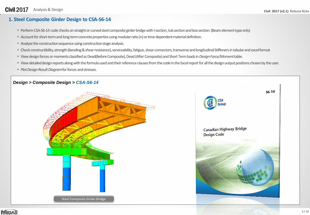
1. Steel Composite Girder Design to CSA-S6-14
Steel Composite Girder Bridge
Perform CSA-S6-14 code checks on straight or curved steel composite girder bridge with I-section, tub section and box section. (Beam element type only)
Account for short-term and long-term concrete properties using modular ratio (n) or time dependent material definition.
Analyze the construction sequence using construction stage analysis.
Check constructibility, strength (bending & shear resistance), serviceability, fatigue, shear connectors, transverse and longitudinal Stiffeners in tabular and excel format
View design forces or moments classified as Dead(Before Composite), Dead (After Composite) and Short Term loads in Design Force/Moment table.
View detailed design reports along with the formula used and their reference clauses from the code in the Excel report for all the design output positions chosen by the user.
Plot Design Result Diagram for forces and stresses.
Design > Composite Design > CSA-S6-14

4 / 22
Civil 2017 (v2.1) Release Note Civil 2017 Analysis & Design
2. PSC Composite Girder Design to CSA-S6-14
PSC > Design Parameters > CSA-S6-14
PSC Composite Girder Bridge Pretensioned Girder
PSC composite section design is now available as per CSA-S6-14.
Composite section for construction stages considering time dependent material can be considered with consideration of tendons and reinforcement in each stage (before and after
composite effect).
Ultimate Limit State (Bending, Shear resistance) and Service Limit State (crack, stress check) design is provided. All checks can be viewed in the Excel calculation report.
Design results can be checked in the result tables for strength (bending, shear) and stress under construction and service loads, and tendons. PSC result diagram for forces and stress is
also provided.
5 / 22
Civil 2017 (v2.1) Release Note Civil 2017 Analysis & Design
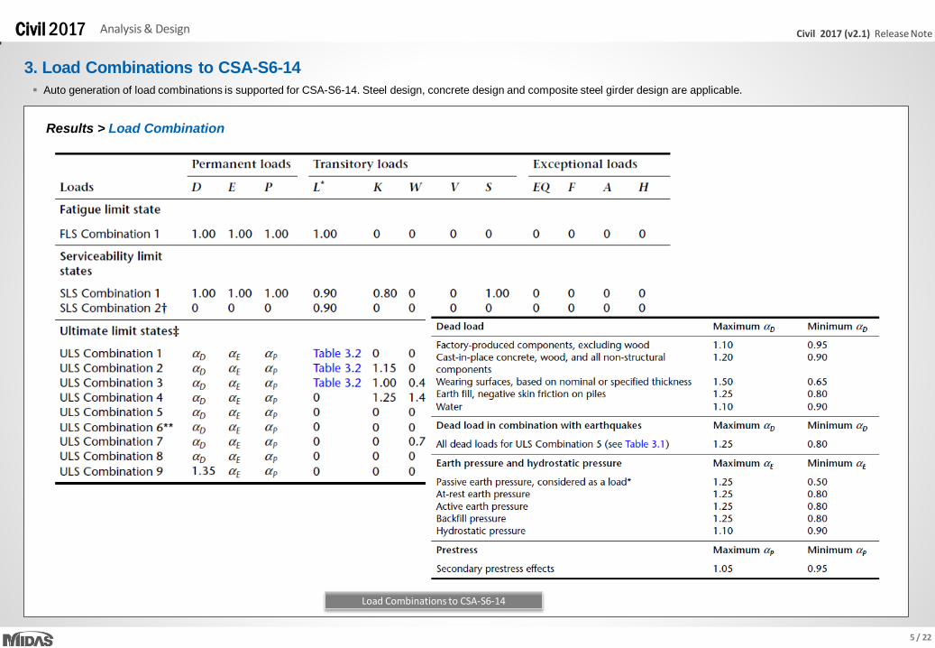
3. Load Combinations to CSA-S6-14
Auto generation of load combinations is supported for CSA-S6-14. Steel design, concrete design and composite steel girder design are applicable.
Results > Load Combination
Load Combinations to CSA-S6-14
6 / 22
Civil 2017 (v2.1) Release Note Civil 2017 Analysis & Design
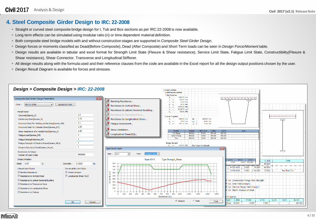
Straight or curved steel composite bridge design for I, Tub and Box sections as per IRC:22-2008 is now available.
Long term effects can be simulated using modular ratio (n) or time dependent material definition.
Both composite steel bridge models with and without construction stages are supported in Composite Steel Girder Design.
Design forces or moments classified as Dead(Before Composite), Dead (After Composite) and Short Term loads can be seen in Design Force/Moment table.
Design results are available in tabular and excel format for Strength Limit State (Flexure & Shear resistance), Service Limit State, Fatigue Limit State, Constructibility(Flexure &
Shear resistance), Shear Connector, Transverse and Longitudinal Stiffener.
All design results along with the formula used and their reference clauses from the code are available in the Excel report for all the design output positions chosen by the user.
Design Result Diagram is available for forces and stresses.
Design > Composite Design > IRC: 22-2008
4. Steel Composite Girder Design to IRC: 22-2008

7 / 22
Civil 2017 (v2.1) Release Note Civil 2017 Analysis & Design
5. Moving Load Optimization (AASHTO, BS, Eurocode)
Load > Moving Load > Traffic Line/Surface Lane > Moving Load Optimization
Load > Moving Load > Moving Load Cases
• In the previous versions, moving load analysis was used to find critical vehicle locations on bridges in the longitudinal direction. The critical locations of vehicles in the transverse direction
were determined by the user based on their experiences or trial-and-error approach.
• Now, Moving Load Optimization complements and extends the capabilities of moving load analysis and helps to significantly simplify the evaluation of critical vehicle locations. The critical
locations of vehicles will be identified in the transverse direction as well as longitudinal direction according to the code provision.
• It reduces the amount of time spent defining lanes and leads to more economical design.
• Other regional codes will be included in the next upgrades.
Traffic Line Lane Optimization Moving Load Case Road Bridge

8 / 22
Civil 2017 (v2.1) Release Note Civil 2017 Analysis & Design
5. Moving Load Optimization (AASHTO, BS, Eurocode)
Lane 1 Lane 2 Lane 3 Lane 4
Carriageway width = 16m
Minimum vehicle distance = 1100 mm
Centerline of carriageway
An example of Moving Load Optimization to find the worst position of vehicles for the leftmost side of carriageway
Lane width = 3500 mm
Wheel spacing = 1900 mm Margin = 550 mm
9 / 22
Civil 2017 (v2.1) Release Note Civil 2017 Analysis & Design
5. Moving Load Optimization (AASHTO, BS, Eurocode)
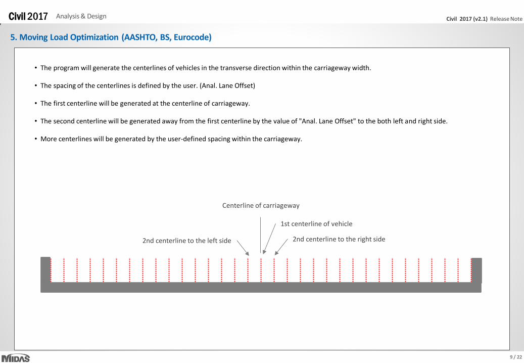
Centerline of carriageway
1st centerline of vehicle
2nd centerline to the left side 2nd centerline to the right side
• The program will generate the centerlines of vehicles in the transverse direction within the carriageway width. • The spacing of the centerlines is defined by the user. (Anal. Lane Offset) • The first centerline will be generated at the centerline of carriageway. • The second centerline will be generated away from the first centerline by the value of "Anal. Lane Offset" to the both left and right side. • More centerlines will be generated by the user-defined spacing within the carriageway.
10 / 22
Civil 2017 (v2.1) Release Note Civil 2017 Analysis & Design
5. Moving Load Optimization (AASHTO, BS, Eurocode)
1500
Removed
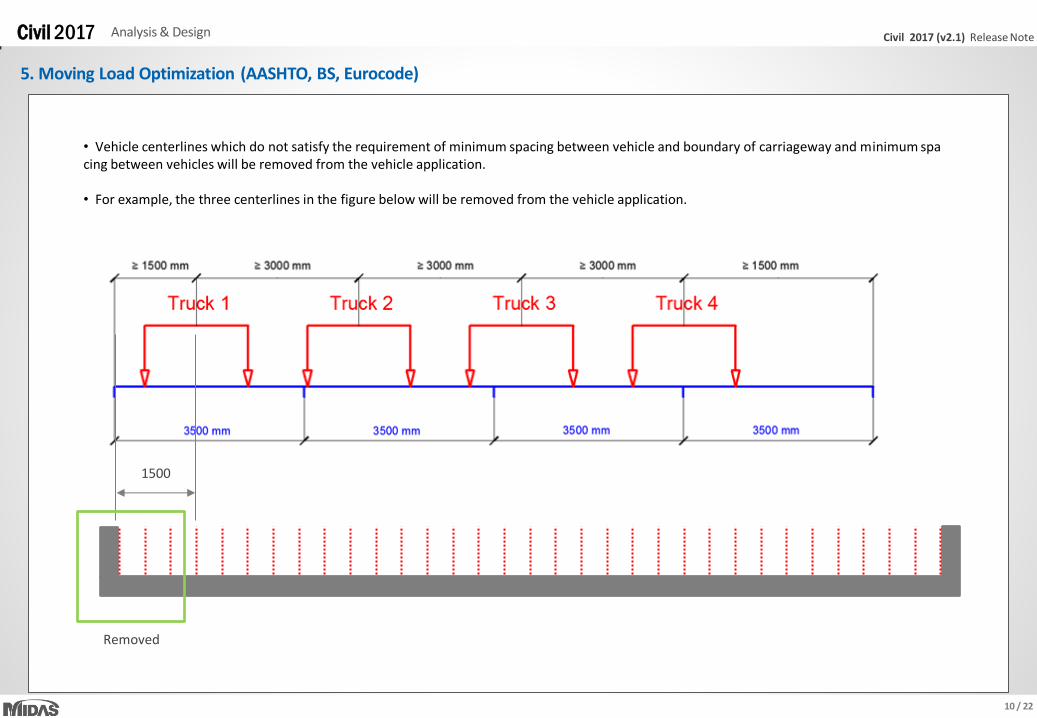
• Vehicle centerlines which do not satisfy the requirement of minimum spacing between vehicle and boundary of carriageway and minimum spacing between vehicles will be removed from the vehicle application. • For example, the three centerlines in the figure below will be removed from the vehicle application.
11 / 22
Civil 2017 (v2.1) Release Note Civil 2017 Analysis & Design
5. Moving Load Optimization (AASHTO, BS, Eurocode)
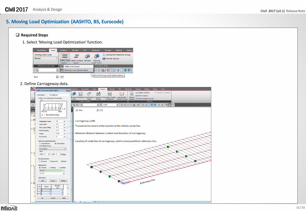
1. Select ‘Moving Load Optimization' function.
Required Steps
2. Define Carriageway data.
12 / 22
Civil 2017 (v2.1) Release Note Civil 2017 Analysis & Design
5. Moving Load Optimization (AASHTO, BS, Eurocode)
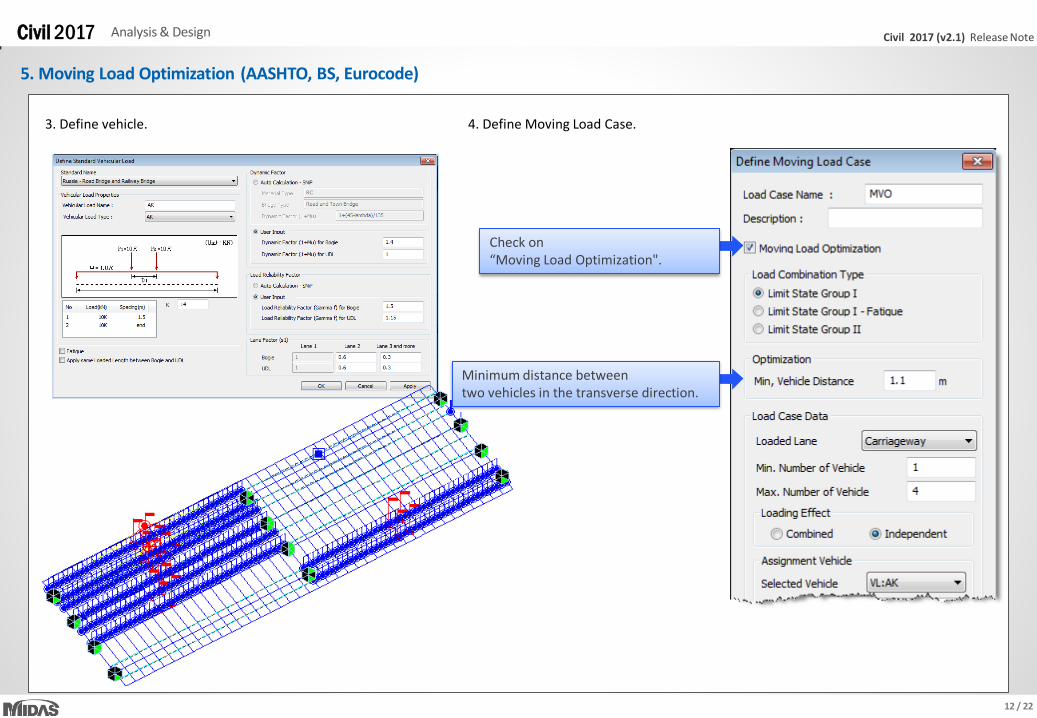
3. Define vehicle. 4. Define Moving Load Case.
Minimum distance between two vehicles in the transverse direction.
Check on “Moving Load Optimization".
13 / 22
Civil 2017 (v2.1) Release Note Civil 2017 Analysis & Design
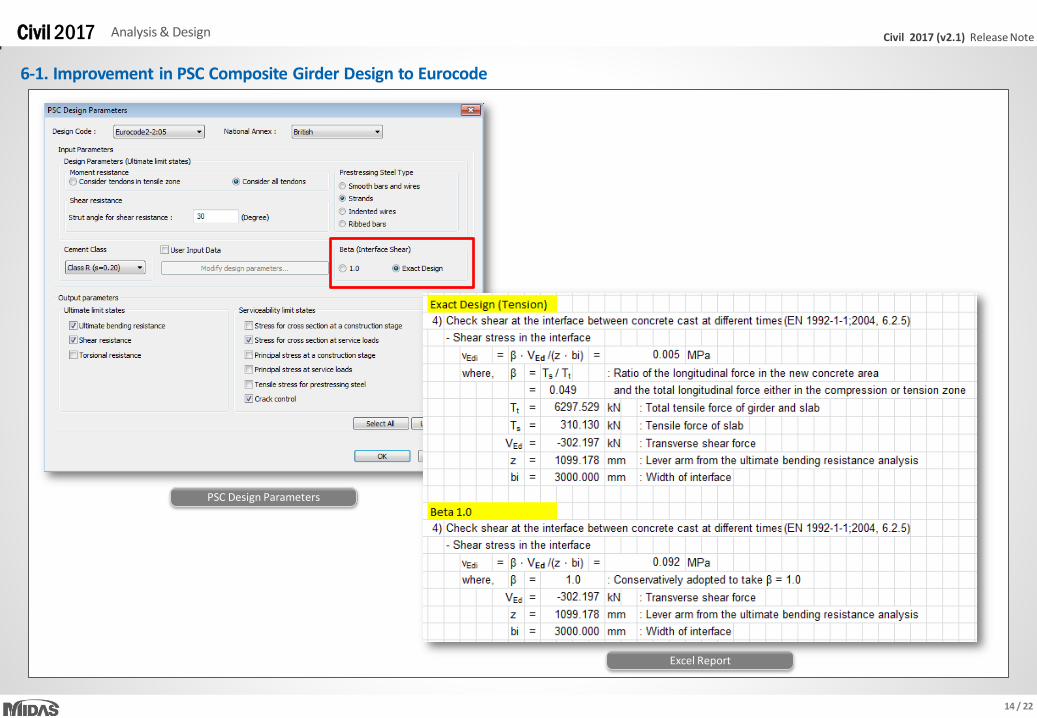
6-1. Improvement in PSC Composite Girder Design to Eurocode6
PSC > Design Parameter > Parameters > Eurocode 2-2:05
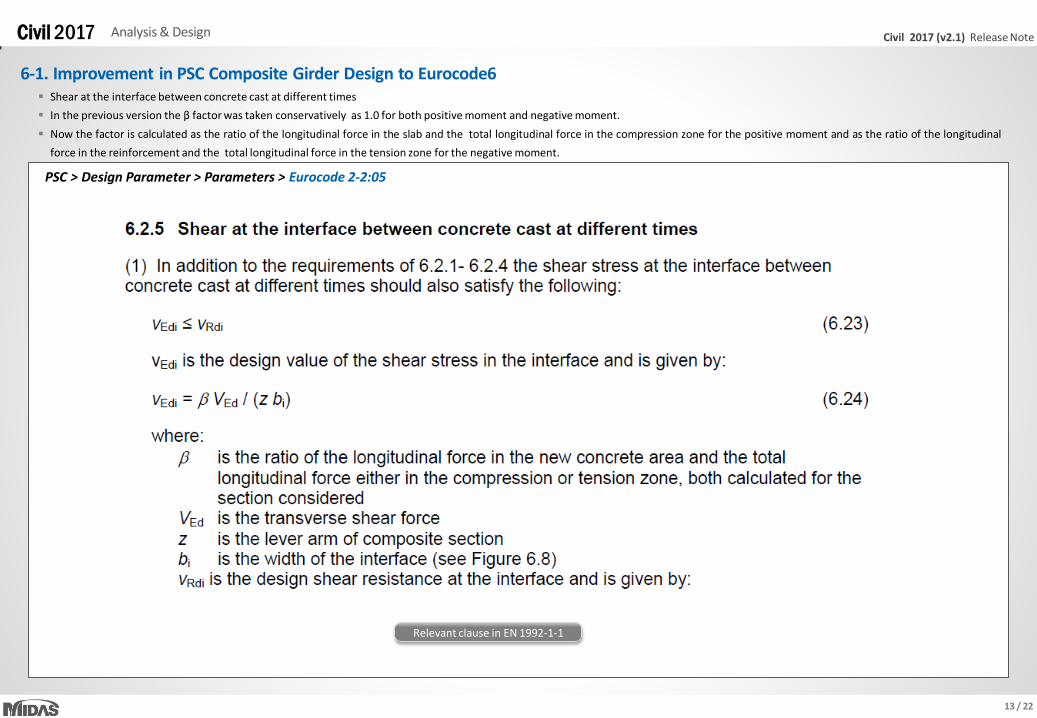
Shear at the interface between concrete cast at different times
In the previous version the β factor was taken conservatively as 1.0 for both positive moment and negative moment.
Now the factor is calculated as the ratio of the longitudinal force in the slab and the total longitudinal force in the compression zone for the positive moment and as the ratio of the longitudinal
force in the reinforcement and the total longitudinal force in the tension zone for the negative moment.
Relevant clause in EN 1992-1-1
14 / 22
Civil 2017 (v2.1) Release Note Civil 2017 Analysis & Design
6-1. Improvement in PSC Composite Girder Design to Eurocode
PSC Design Parameters
Excel Report
15 / 22
Civil 2017 (v2.1) Release Note Civil 2017 Analysis & Design
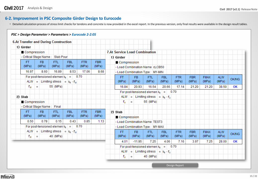
6-2. Improvement in PSC Composite Girder Design to Eurocode Detailed calculation process of stress limit checks for tendons and concrete is now provided in the excel report. In the previous version, only final results were available in the design result tables.
Design Report
PSC > Design Parameter > Parameters > Eurocode 2-2:05

16 / 22
Civil 2017 (v2.1) Release Note Civil 2017 Analysis & Design
6-3. Improvement in PSC Composite Girder Design to Eurocode According to clause 7.3.2 (4) of EN 1992-1-1, check whether no minimum reinforcement is required.
Relevant clause in EN 1992-1-1
Design Report
PSC > Design Parameter > Parameters > Eurocode 2-2:05

17 / 22
Civil 2017 (v2.1) Release Note Civil 2017 Analysis & Design
7-1. Improvement in Moving Load Analysis to BS
Load > Moving Load Cods > BS
• In the previous version, the SV-train vehicle was not applied alone on the traffic lane.
• This is fixed now as shown below.
Moving Load Tracer (Previous version)
Moving Load Tracer (Civil 2017 (v2.1))
SV-train
HA vehicle

18 / 22
Civil 2017 (v2.1) Release Note Civil 2017 Analysis & Design
7-2. Improvement in Moving Load Analysis to BS • Both forward moving and backward moving of vehicles can be now considered with one moving load case. For the BS code.
Previous Version
Load > Moving Load Analysis Data > Traffic Line Lanes, Traffic Surface Lanes
Civil 2017 (v2.1)
19 / 22
Civil 2017 (v2.1) Release Note Civil 2017 Analysis & Design
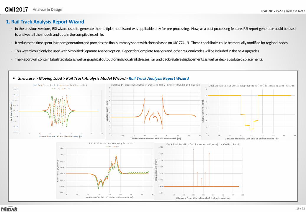
1. Rail Track Analysis Report Wizard
Structure > Moving Load > Rail Track Analysis Model Wizard> Rail Track Analysis Report Wizard
• In the previous versions, RSI wizard used to generate the multiple models and was applicable only for pre-processing. Now, as a post processing feature, RSI report generator could be used
to analyze all the models and obtain the compiled excel file.
• It reduces the time spent in report generation and provides the final summary sheet with checks based on UIC 774 - 3. These check limits could be manually modified for regional codes
• This wizard could only be used with Simplified Separate Analysis option. Report for Complete Analysis and other regional codes will be included in the next upgrades.
• The Report will contain tabulated data as well as graphical output for individual rail stresses, rail and deck relative displacements as well as deck absolute displacements.

20 / 22
Civil 2017 (v2.1) Release Note Civil 2017 Analysis & Design
1. Rail Track Analysis Report Wizard
Structure > Moving Load > Rail Track Analysis Model Wizard> Rail Track Analysis Report Wizard
• In the previous versions, RSI wizard used to generate the multiple models and was applicable only for pre-processing. Now, as a post processing feature, RSI report generator could be used
to analyze all the models and obtain the compiled excel file.
• It reduces the time spent in report generation and provides the final summary sheet with checks based on UIC 774 - 3. These check limits could be manually modified for regional codes
• This wizard could only be used with Simplified Separate Analysis option. Report for Complete Analysis and other regional codes will be included in the next upgrades.
• The Report will contain tabulated data as well as graphical output for individual rail stresses, rail and deck relative displacements as well as deck absolute displacements.
21 / 22
Civil 2017 (v2.1) Release Note Civil 2017 Analysis & Design
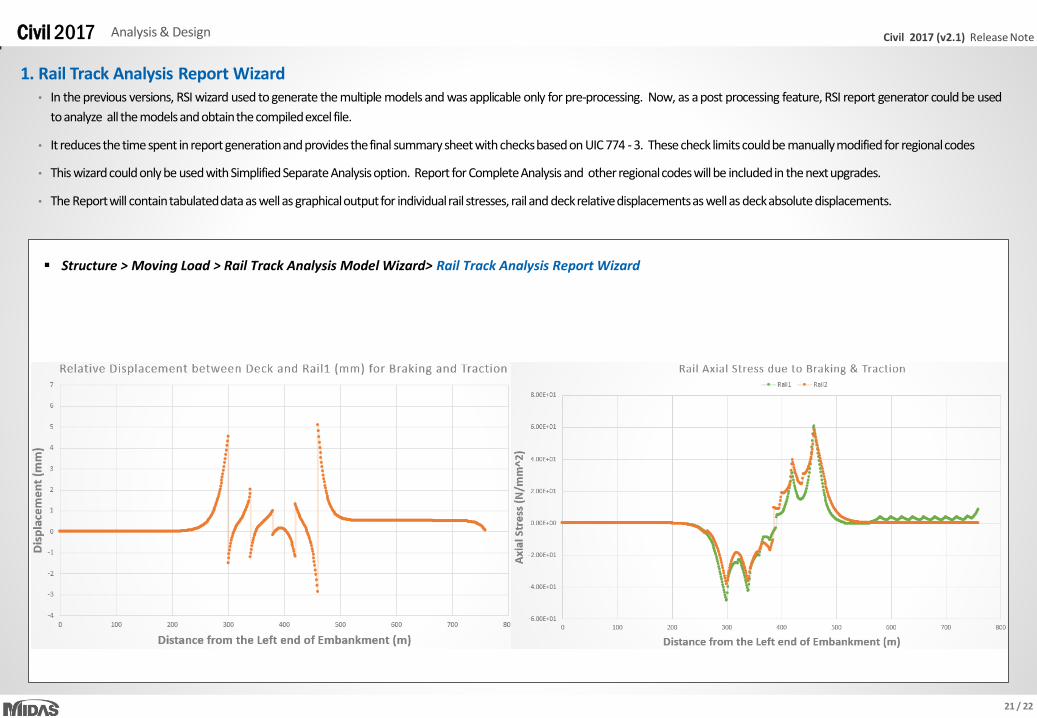
1. Rail Track Analysis Report Wizard
Structure > Moving Load > Rail Track Analysis Model Wizard> Rail Track Analysis Report Wizard
• In the previous versions, RSI wizard used to generate the multiple models and was applicable only for pre-processing. Now, as a post processing feature, RSI report generator could be used
to analyze all the models and obtain the compiled excel file.
• It reduces the time spent in report generation and provides the final summary sheet with checks based on UIC 774 - 3. These check limits could be manually modified for regional codes
• This wizard could only be used with Simplified Separate Analysis option. Report for Complete Analysis and other regional codes will be included in the next upgrades.
• The Report will contain tabulated data as well as graphical output for individual rail stresses, rail and deck relative displacements as well as deck absolute displacements.
22 / 22
Civil 2017 (v2.1) Release Note Civil 2017 Analysis & Design
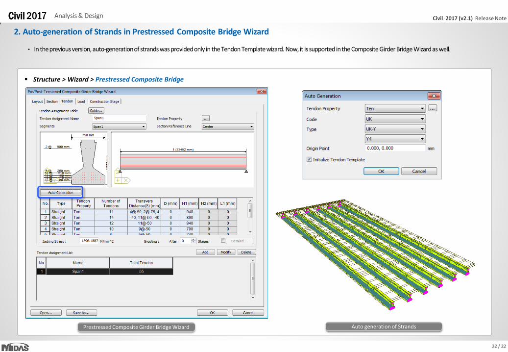
2. Auto-generation of Strands in Prestressed Composite Bridge Wizard
Structure > Wizard > Prestressed Composite Bridge
Prestressed Composite Girder Bridge Wizard Auto generation of Strands
• In the previous version, auto-generation of strands was provided only in the Tendon Template wizard. Now, it is supported in the Composite Girder Bridge Wizard as well.


![· PDF fileDie im UIC-Merkblatt 774- 3 [1] maximal zulässige Längsverschie- bung von ±7 mm wurde im Dauerversuch auf mm erhöht, damit mit edilon)(se](https://img.dokumen.tips/doc/110x75/5a9e1d317f8b9ad2298d7354/im-uic-merkblatt-774-3-1-maximal-zulssige-lngsverschie-bung-von-7-mm-wurde-im.jpg)


![UIC 774 3 Code for Track Rail Interaction[1]](https://img.dokumen.tips/doc/110x75/5435b17b219acdd95f8b4b17/uic-774-3-code-for-track-rail-interaction1.jpg)


