Embed Size (px)
Citation preview

Pumper Operator Pump Operation (Part II)
Jim Whelan 1 1/26/00
LESSON PLAN #PO-2 TITLE: PUMP OPERATION (Part II) TIME REQ'D: Eight (8) hours STANDARD: NFPA !002 (1998 Edition) INST. LEVEL: Levels 1 - 2 - 3 Knowledge - Comprehension - Application MAT. NEEDED: • Slide Projector • Slides • TV / VCR • Fire Engineering Video "Master Stream Safety" • Student Handouts • Minimum Three (3) Apparatus with Rated Pumps • Water Supply • static • pressurized • Monitors • portable • deck mounted • Test Gauges • Flow Meter / Flow Test Kit / Pitot Gauge REFERENCE: IFSTA "Fire Department Pumping Apparatus", 7th Edition IFSTA "Fire Stream Practices", 7th Edition OBJECTIVE: At the end of this class, each apparatus operator shall be able to: SM Pg. 1 1. Identify the percentages of rated capacity, rated
pressures, and the capacity in gallons per minute at the rated pressures a fire department pumper is designed to deliver.
2. Demonstrate production of effective master streams, using multiple lines.
3. Demonstrate procedures for the following: a. relay pumping b. tandem pumping

Pumper Operator Pump Operation (Part II)
Jim Whelan 2 1/26/00
c. dual pumping d. taking over a hydrant 4. Demonstrate procedures for conducting an annual
pumper service test. Evaluation shall be in the form of a short written test which requires a
minimum score of 70% and several task performances which must be completed satisfactorily to receive credit for the class.
MOTIVATION: Although there are numerous models and types of fire pumps used
on fire department apparatus, most are designed to perform the same general function. Because of this similarity, a pump operator can do an adequate job of operating any piece of apparatus by applying fundamental principles. These principles, along with proper training, practice, and a thorough knowledge of water supply, must be understood well before a firefighter can become a proficient and effective apparatus operator. (IFSTA)
OVERVIEW: In this class we will cover: 1. Master streams 2. Dual pumping 3. Tandem pumping 4. Relay pumping 5. Taking over a hydrant 6. Rated pumping capacities 7. Pumper tests PRESENTATION: I. MASTER STREAMS A. Definition of (IFSTA): 1. "Any of a variety of heavy, large-caliber water
streams; usually supplied by siamesing two or more hoselines into a manifold device capable of delivering a minimum of 350 gpm."
NOTE
MASTER STREAM DEVICES CAN BE EQUIPPED WITH NOZZLES WHICH DEVELOP FLOWS RANGING FROM 350 GPM TO 2000 GPM. B. Three (3) Main Uses 1. Direct fire attack

Pumper Operator Pump Operation (Part II)
Jim Whelan 3 1/26/00
a. Offensive b. Defensive 2. Backup for handlines already in place 3. Exposure protection C. Placement 1. Must be properly placed before being put in
service a. Usually difficult to move after water starts
to flow
HOSE WEIGHTS INCLUDING WATER Average Hose, Coupling, Water, per 100’
Hose Coupling Water Total 1 1/2” 31.00# 1.00# 78# 110.0# 1 3/4” 35.50# 1.50# 104# 141.0# 2 1/2” 53.50# 2.50# 223# 279.0#
3” 66.75# 3.75# 306# 376.5# 4” 77.25# 7.75# 544# 629.0# 5” 98.50# 10.50# 850# 959.0#
2. When operating through door or window, place
appliance close enough to reach seat of fire 3. Stream should enter structure at upward angle a. Permits stream to bounce off ceiling or
other overhead objects and be broken down into small droplets
(1) smaller drops: (1) act as rain and fall on fire (b) provide greater surface
area for optimum heat absorption
4. Place appliance to optimize stream coverage,
ie:

Pumper Operator Pump Operation (Part II)
Jim Whelan 4 1/26/00
a. Cover as much of exposure as possible b. Hit maximum number of openings SM Pg. 2 D. Supplying 1. Flows large volumes of water which can
generate large amount of friction loss a. Keep friction loss to minimum by using: (1) larger diameter supply line(s) (a) 2 1/2" minimum (2) short lays (a) requires thought be given
to apparatus placement as well as master stream placement
2. Small diameter (2 1/2" - 3") supply hose bed
loads should be set up for dual lay to reduce set-up time
E. Safety
SAFETY NOTE A MASTER STREAM FLOWS A LARGE VOLUME OF WATER WHICH CREATES SUBSTANTIAL ENERGY. THE NOZZLE REACTION PRODUCED BY THE DISCHARGE STREAM CAN BE EXTREMELY POWERFUL. CARE MUST BE TAKEN DURING THE OPERATION OF THESE MASTER STREAMS TO INSURE THEY DO NOT INJURE SOMEONE. ALL PERSONNEL SHOULD BE FAMILIAR WITH THE OPERATION OF MASTER STREAMS AS USED BY THEIR RESPECTIVE FIRE DEPARTMENTS. 1. Never direct master streams into occupied
areas 2. Prevent personnel from walking into streams 3. When flowing portable master stream, follow
basic guidelines:

Pumper Operator Pump Operation (Part II)
Jim Whelan 5 1/26/00
a. Maintain ground spikes b. Keep hoselines straight behind inlet for
minimum of 10' (1) tie hoses together as added
safety precaution c. Before flowing: (1) secure device with rope or chain (2) check manufacturer's elevation
safety stop (a) prevents nozzle reaction
from picking up device and injuring personnel
d. Do not: (1) attempt to hold appliance in place (2) exceed manufacturer's limits (a) pressure (b) flow
INSTRUCTOR NOTE SHOW FIRE ENGINEERING VIDEO "MASTER STREAM SAFETY"
II. DUAL PUMPING
NOTE "DUAL PUMPING" IS OFTEN INCORRECTLY REFERRED TO AS "TANDEM PUMPING". A. Definition of (IFSTA): 1. "An operation where a strong hydrant is used to
supply two pumpers by connecting the pumpers intake-to-intake. The second pumper receives the excess water not being pumped by the first pumper, which is directly connected to the water supply source."
SM Pg. 3 B. Advantages

Pumper Operator Pump Operation (Part II)
Jim Whelan 6 1/26/00
1. Better use of water supply 2. Additional hoselines may be placed into
operation faster 3. Improved coordination, ie.: a. Tighter apparatus positioning b. Shorter hose lays C. Procedure 1. First pumper connects to hydrant steamer port
using large diameter suction 2. This pumper starts to supply water to incident 3. Second pumper positioned intake-to-intake with
first pumper 4. Water supply to first pumper restricted until
residual pressure on compound gauge reads near zero (5 psi approx.)
a. Water flow to first pumper may be
controlled by closing either: (1) intake valve (2) hydrant b. Use of intake valve preferred to that of
hydrant c. Partially closing hydrant will discharge
water under pressure from drain hole and could wash out hydrant
5. Throttle of first pumper may need adjusting 6. Intake water volume now equal to discharge
water volume, allowing removal of unused intake cap
NOTE

Pumper Operator Pump Operation (Part II)
Jim Whelan 7 1/26/00
IF THE FIRST PUMPER IS EQUIPPED WITH A VALVE ON THE UNUSED INTAKE, THE WATER SUPPLY NEED NOT BE RESTRICTED. 7. Second pumper connected to unused steamer
intake of first pumper with large diameter suction
8. Water supply fully restored to first pumper 9. Second pumper supplies water to incident
NOTE THE WATER SUPPLY FOR THE SECOND PUMPER IS THE WATER NOT USED BY, AND IS PASSING THROUGH, THE FIRST PUMPER. III. TANDEM PUMPING A. Definition of (IFSTA): 1. "A short relay operation in which the pumper
taking water from the supply source pumps into the intake of the second pumper. The second pumper boosts the pressure of the water even higher. This method is used when pressures higher than the capability of a single pump are required."
B. Commonly used when attack pumper located close to
hydrant and needs to overcome friction loss problems which occur in:
1. Large sprinkler or standpipe systems 2. Long hose lays SM Pg. 4 C. Procedure 1. Pumper directly connected to water supply
pumps through its discharge outlet(s) into intake(s) of second engine
2. Pumpers generally not over 300 feet apart
SAFETY NOTE IN TANDEM PUMPING OPERATIONS IT IS POSSIBLE TO SUPPLY PRESSURES GREATER THAN THE HOSELINES CAN WITHSTAND.

Pumper Operator Pump Operation (Part II)
Jim Whelan 8 1/26/00
THE PRESSURE DEVELOPED SHOULD NEVER EXCEED THE PRESSURE TO WHICH THE HOSE IS ANNUALLY TESTED. IV. TAKING OVER A HYDRANT A. Procedure used to overcome friction loss encountered
when trying to: 1. Flow large volume of water 2. Long distance 3. Through small diameter (2 1/2" or 3") supply
line(s) B. Engine taking over hydrant: 1. Responsible for overcoming friction loss in
supply line 2. Not responsible for providing hose lines or fire
streams for fire attack
NOTE IF THE LAY-IN EXCEEDS 1,000 FEET, SET UP A RELAY OPERATION INSTEAD OF TAKING OVER THE HYDRANT. C. Procedure 1. First in engine (Engine 1) stops at hydrant and
drops two (2) lines a. One (1) wet b. One (1) dry 2. Connect "wet" line with gate valve to one side of
hydrant and second gate valve to appropriate preplanned hydrant discharge port
NOTE
PREPLANNING IS THE KEY TO DEVELOPING A SUPPLY LINE CONFIGURATION THAT MAXIMIZES HYDRANT FLOW AND MINIMIZES FRICTION LOSS.
NOTE DRY LINE IS NOT CONNECTED TO ANYTHING AT THIS POINT.

Pumper Operator Pump Operation (Part II)
Jim Whelan 9 1/26/00
3. Turn on hydrant, charging "wet" line, when engineer ready for water
4. Second in engine (Engine 2) spots apparatus to
pump from hydrant SM Pg. 5 5. Engine 2 connects: a. Soft suction hose to hydrant gate b. "Dry" line to pump discharge port 6. "Dry" line charged after getting approval from
Engine 1 7. Engine 2 notifies Engine 1 they are shutting
down hydrant ("wet") line 8. Engine 2: a. Shuts down "wet" line gate valve b. Connects hydrant line to pump discharge
port c. Charges "wet" line with approval from
Engine 1 d. Sets pump discharge pressure at
required setting to provide volume of water desired
NOTE
SOMETIMES THE FIRST IN ENGINE WILL LAY JUST ONE SUPPLY LINE FROM THE HYDRANT TO THE FIRE BASED ON CONDITIONS AT THAT TIME. IF THINGS SHOULD DETERIORATE AND MORE WATER IS NEEDED, A VARIATION OF TAKING OVER A HYDRANT MAY BE USED. COMMUNICATION BETWEEN ENGINEERS IS ESSENTIAL FOR THIS PROCEDURE TO WORK PROPERLY AS IT REQUIRES COORDINATED EFFORTS BETWEEN THEM. D. Variation 1. Engine 1 connects to hydrant with one (1)
supply line and proceeds as normal 2. Upon realizing they need more water they ask
Engine 2 to supply it

Pumper Operator Pump Operation (Part II)
Jim Whelan 10 1/26/00
3. Engine 2 makes a reverse lay, dropping required number of lines to flow volume of water Engine 1 needs
4. Engine 2: a. Spots to pump from hydrant b. Connects all lines they dropped to
discharge ports c. Charges one (1) line, using tank water,
with approval from Engine 1 d. Shuts down hydrant as soon as Engine 1
gives approval e. Connects to hydrant and makes
transition from tank water to hydrant
SAFETY NOTE THE TRANSITION FROM TANK WATER TO HYDRANT WATER MUST HAPPEN BEFORE THE TANK WATER IS DEPLETED. FAILURE TO DO SO COULD BE DISASTROUS. d. Connects original supply to discharge
port and charges with approval from Engine 1
e. Charges additional lines if required after
receiving approval from Engine 1 f. Sets discharge pressure to deliver
required volume of water to Engine 1 V. RATED PUMPING CAPACITIES A. Capacity 1. Definition of (for this class): a. "The volume of water that a pump can
discharge from a static source draft at a certain pressure each minute"
B. Rated Capacity is:

Pumper Operator Pump Operation (Part II)
Jim Whelan 11 1/26/00
1. One means of identifying pump capabilities 2. Determined by testing 3. Not necessarily maximum capacity of pump SM Pg. 6 4. Actual capacity of centrifugal pumps limited by
design features a. Intake diameter b. Impeller eye diameter c. Outside diameter of impeller d. Width of impeller e. Shape and number of impeller vanes f. Design of volute chamber 5. Capacity of positive displacement pump limited
by: a. Pump displacement b. Pump speed (1) revolutions per minute (rpm) 6. To pass test and be rated, fire pumps must
meet following capacity and pressure requirements:
a. 100% of rated capacity @ 150 PSI (1) 750 gpm rated pump must
produce 750 gpm at 150 psi (2) 1000 gpm rated pump must
produce 1000 gpm at 150 psi (3) 1500 gpm rated pump must
produce 1500 gpm at 150 psi b. 70% of rated capacity @ 200 PSI

Pumper Operator Pump Operation (Part II)
Jim Whelan 12 1/26/00
(1) 750 gpm rated pump must produce 525 gpm at 200 psi
(2) 1000 gpm rated pump must
produce 700 gpm at 200 psi (3) 1500 gpm rated pump must
produce 1050 gpm at 200 psi c. 50% of rated capacity @ 250 PSI (1) 750 gpm rated pump must
produce 375 gpm at 250 psi (2) 1000 gpm rated pump must
produce 500 gpm at 250 psi (3) 1500 gpm rated pump must
produce 750 gpm at 250 psi 7. Insurance Services Office requires pumps be
tested annually VI. RELAY PUMPING A. Definition of (IFSTA): 1. "The process of using two or more pumpers to
move water through hoselines over a long distance by operating the pumpers in series."
NOTE
PUMPING IN RELAY IS USUALLY REQUIRED ANYTIME THE WATER SOURCE IS LOCATED MORE THAN A FEW HUNDRED FEET FROM THE FIRE. RELAY PUMPING IS NOTHING MORE THAN INSERTING FIRE PUMPS INTO SUPPLY LINES AT VARIOUS INTERVALS TO COUNTERACT THE EFFECTS OF FRICTION LOSS AND/OR AN INCREASE IN ELEVATION. HOSE SIZE AND HYDRANT PRESSURE ARE KEY FACTORS TO CONSIDER WHEN DECIDING IF A RELAY OPERATION IS NEEDED. B. Requirements 1. Relay operations dependent on: a. Fire flow requirements / Amount of water
needed

Pumper Operator Pump Operation (Part II)
Jim Whelan 13 1/26/00
b. Distance between water supply and incident
c. Hose size d. Pumper capacity e. Terrain C. Limitations 1. Rated pump capacities a. Pumps produce maximum gallonage at
150 psi b. Pumping at pressures above 150 psi will
result in decreased flows 2. Pressure restrictions demanded by use of fire
hose a. Most hose tested annually at 250 psi b. 200 psi maximum relay flow pressure to
allow for: (1) deterioration of hose (2) pressure fluctuations during
operation
NOTE SINCE THE MAXIMUM PUMP DISCHARGE PRESSURE OF A RELAY PUMPER IS 200 PSI AND THE MINIMUM INTAKE PRESSURE OF THE NEXT PUMPER IN THE LINE IS 20 PSI, 180 PSI IS THE MOST THAT CAN BE LOST TO FRICTION LOSS AND ELEVATION BETWEEN ANY TWO ENGINES, ANYWHERE IN THE RELAY. D. Designing Relay Operations 1. Formula to determine number of pumpers
needed to relay specific quantity of water SM Pg. 7 a. TPN = RD ÷ TD + 1 (1) TPN = Total Pumpers Needed (2) RD = Relay Distance

Pumper Operator Pump Operation (Part II)
Jim Whelan 14 1/26/00
(3) TD = Table Distance (consult
table directly below)
MAXIMUM DISTANCE OF WATER FLOW AT 180 PSI(in feet) Flow Hose Diameter (inches)
in GPM 2 1/2 3 4 5 6 100 9,000 22,500 90,000 225,000 360,000 200 2,250 5,625 22,500 56,200 90,000 250 1,440 3,600 14,400 36,000 57,600 300 1,000 2,500 10,000 25,000 40,000 400 563 1,406 5,625 14,060 22,500 500 360 900 3,600 9,000 14,000 750 160 400 1,600 4,000 6,400 1000 90 225 900 2,250 3,600
2. How many pumpers would be required to run
500 gpm, 1000 ft., using 2 1/2" hose? a. TPN = RD ÷ TD + 1 b. TPN = 1000 ÷ 360 + 1 c. TPN = 2.77 + 1 d. TPN = 3.77 or 4 pumpers 3. How many pumpers would be required to run
750 gpm, 700 ft., using 3" hose? a. TPN = RD ÷ TD + 1 b. TPN = 700 ÷ 400 + 1 c. TPN = 1.75 + 1 d. TPN = 2.75 or 3 pumpers 4. How many pumpers would be required to run
1000 gpm, 1800 ft., using a double lay of 3" hose?
a. TPN = RD ÷ TD + 1 b. TPN = 1800 ÷ 900 + 1 c. TPN = 2 + 1

Pumper Operator Pump Operation (Part II)
Jim Whelan 15 1/26/00
d. TPN = 3 pumpers 5. How many pumpers would be required to run
1000 gpm, 4500 ft., using 5" hose? a. TPN = RD ÷ TD + 1 b. TPN = 4500 ÷ 2250 + 1 c. TPN = 2 + 1 d. TPN = 3 pumpers
NOTE THE NUMBER OF PUMPERS NECESSARY AS SHOWN IN THE LAST TWO EXAMPLES ABOVE IS SUFFICIENT ONLY IF EACH PUMPER IS CAPABLE OF DELIVERING 1000 GPM AT 180 PSI.
INSTRUCTOR NOTE ASK STUDENTS WHAT THE RATED CAPACITY OF THE PUMP MUST BE TO DELIVER 1000 GPM AT 180 PSI. (Student response should be 1500 gpm, ie. 70% of 1500 is 1050) 6. Largest capacity pumper should be located at
water supply a. If drafting from static source, first pumper
will need to develop higher net pump discharge pressure
b. Subsequent pumpers will have minimum
20 psi residual pressure, reducing amount of net pump discharge pressure
NOTE
THE MAXIMUM CAPACITY OF THE RELAY WILL BE DETERMINED BY THE CAPACITY OF THE SMALLEST PUMPER AND SMALLEST HOSELINE USED WITHIN THE RELAY. E. Starting Relay Operations 1. Initial or source pumper establishes water
supply, dumping water through dump line until next pumper in relay ready
2. On command, source pumper slowly:

Pumper Operator Pump Operation (Part II)
Jim Whelan 16 1/26/00
a. Opens relay discharge lines b. Closes dump line valve c. Flows water to relay pumper d. Increases discharge pressure to
calculated setting
INSTRUCTOR NOTE ASK STUDENTS "WHAT DETERMINES THE CALCULATED PRESSURE?"
ASK STUDENTS "WHO DETERMINES PRESSURE?" SM Pg. 8
SAFETY NOTE VALVES SHOULD BE OPENED SLOWLY TO PREVENT WATER HAMMER. 3. Relay operator should: a. Wait with dump line discharge open and
pump disengaged b. Bleed all air from hoseline(s) and engage
pump c. Adjust dump line discharge valve to allow
maximum residual pump pressure of 50 psi
d. Slowly increase pump pressure to
calculated setting while closing dump line discharge to keep residual pump pressure at 50 psi
4. Relay established once relay pumper reaches
calculated pressure with dump line flowing, further adjustments should not be necessary
5. Follow same basic procedure to supply second
relay pumper 6. First relay operator should slowly: a. Open relay discharge lines and close
dump line valve, while maintaining residual pump pressure of 50 psi
Pumper Operator Pump Operation (Part II)
Jim Whelan 17 1/26/00
b. Flow water to relay pumper c. Increase discharge pressure to
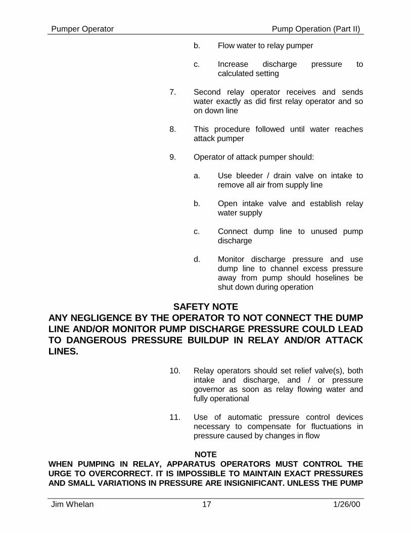
calculated setting 7. Second relay operator receives and sends
water exactly as did first relay operator and so on down line
8. This procedure followed until water reaches
attack pumper 9. Operator of attack pumper should: a. Use bleeder / drain valve on intake to
remove all air from supply line b. Open intake valve and establish relay
water supply c. Connect dump line to unused pump
discharge d. Monitor discharge pressure and use
dump line to channel excess pressure away from pump should hoselines be shut down during operation
SAFETY NOTE
ANY NEGLIGENCE BY THE OPERATOR TO NOT CONNECT THE DUMP LINE AND/OR MONITOR PUMP DISCHARGE PRESSURE COULD LEAD TO DANGEROUS PRESSURE BUILDUP IN RELAY AND/OR ATTACK LINES. 10. Relay operators should set relief valve(s), both
intake and discharge, and / or pressure governor as soon as relay flowing water and fully operational
11. Use of automatic pressure control devices
necessary to compensate for fluctuations in pressure caused by changes in flow
NOTE
WHEN PUMPING IN RELAY, APPARATUS OPERATORS MUST CONTROL THE URGE TO OVERCORRECT. IT IS IMPOSSIBLE TO MAINTAIN EXACT PRESSURES AND SMALL VARIATIONS IN PRESSURE ARE INSIGNIFICANT. UNLESS THE PUMP

Pumper Operator Pump Operation (Part II)
Jim Whelan 18 1/26/00
INTAKE PRESSURE FALLS BELOW 20 PSI OR EXCEEDS 100 PSI, ALLOW THE RELIEF VALVE(S) AND/OR PRESSURE GOVERNOR TO HANDLE ALL MINOR DISCREPANCIES BECAUSE CHANGES MADE BY ANY ONE OF THE RELAY OPERATORS WILL SHOW UP SOMEPLACE ELSE IN THE RELAY. F. Ending Relay Operations 1. Fire attack pumper should be shut down first a. If source pumper shut down first, relay
pumpers will: (1) run out of water (2) cavitate SM Pg. 9 2. Starting with attack pumper, each operator
should: a. Slowly decrease pressure b. Open dump line c. Disengage pump
SAFETY NOTE EFFECTIVE COMMUNICATIONS ARE ESSENTIAL TO AN EFFICIENT RELAY PUMPING OPERATION. FIREFIGHTER SAFETY COULD BE AT RISK IF RELAY OPERATION NOT COORDINATED.
INSTRUCTOR NOTE ASK STUDENTS TO COMMENT ON HOW FIREFIGHTER SAFETY COULD BE COMPROMISED BY A HAPHAZARD RELAY PUMPING OPERATION. VII. PUMPER TESTS A. Three Kinds 1. Certification 2. Acceptance 3. Service B. Certification Test

Pumper Operator Pump Operation (Part II)
Jim Whelan 19 1/26/00
1. Assures pump performance and tank-to-pump flow rates meet NFPA 1901 requirements
2. Conducted by Underwriters Laboratories (UL) 3. Generally done at site of manufacture a. May be performed at fire department 4. Consists of: a. Vacuum test b. Three hour pump test c. Automatic pump pressure control test d. Tank-to-pump flow rate test C. Acceptance Test 1. Assures purchaser that apparatus meets bid
specifications 2. Usually conducted by purchaser with
manufacturer's representative present 3. Most often performed after apparatus has been
delivered to purchaser, but before acceptance 4. Apparatus can be rejected if it fails to achieve
requirements detailed in bid specifications SM Pg. 10 5. Consists of: a. Acceleration tests (1) 0 - 25 mph (a) within 25 seconds for
apparatus carrying 800 gallons or less
(b) within 30 seconds for
apparatus carrying more than 800 gallons
(2) 15 - 35 mph
Pumper Operator Pump Operation (Part II)
Jim Whelan 20 1/26/00
(a) within 30 seconds without
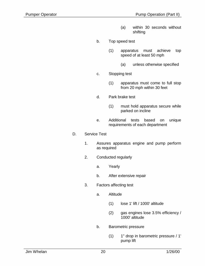
shifting b. Top speed test (1) apparatus must achieve top
speed of at least 50 mph (a) unless otherwise specified c. Stopping test (1) apparatus must come to full stop
from 20 mph within 30 feet d. Park brake test (1) must hold apparatus secure while
parked on incline e. Additional tests based on unique
requirements of each department D. Service Test 1. Assures apparatus engine and pump perform
as required 2. Conducted regularly a. Yearly b. After extensive repair 3. Factors affecting test a. Altitude (1) lose 1' lift / 1000' altitude (2) gas engines lose 3.5% efficiency /
1000' altitude b. Barometric pressure (1) 1" drop in barometric pressure / 1'
pump lift

Pumper Operator Pump Operation (Part II)
Jim Whelan 21 1/26/00
c. Engine RPM (1) do not exceed no-load speed of
manufacturer d. Amount of lift (1) surface of water to center of
intake (2) not to exceed 10 feet (height)
using 20 feet (length) of suction hose
e. Temperature (1) diesel engines lose power above
90° F 4. Net Pump Discharge Pressure a. Tests conducted at 150, 165 (overload),
200, and 250 psi net pump discharge pressure
NOTE
NET PUMP DISCHARGE PRESSURE (NPDP), AS DEFINED IN IFSTA "PUMPING APPARATUS", IS THE TOTAL WORK DONE BY THE PUMP TO GET THE WATER INTO, THROUGH, AND OUT OF THE PUMP. WHEN TAKING WATER FROM A HYDRANT, IT IS THE DIFFERENCE BETWEEN THE INTAKE PRESSURE AND THE DISCHARGE PRESSURE. WHEN DRAFTING, IT IS THE SUM OF THE PUMP DISCHARGE PRESSURE AND THE INTAKE HOSE ALLOWANCE (INTAKE PRESSURE CORRECTION).
FRICTION LOSS ALLOWANCES FOR INTAKE HOSE
Rated Pump Cap. Hose Dia. Allowance (feet) (U.S. GPM) (inches) For 10’ of Hose Each Additional 10’
500
4 4 1/2
6 3 1/2
+1 + 1/2
750
4 1/2 5
7 4 1/2
+1 1/2 +1
1000
4 1/2 5 6
13 8 4
+2 +1 1/2 + 1/2
1250
5 6
12 1/2 6 1/2
+2 + 1/2

Pumper Operator Pump Operation (Part II)
Jim Whelan 22 1/26/00
1500 6 9 +1
b. Intake pressure correction = lift + suction hose friction loss divided by 2.3
(1) IPC = L + SHFL ÷ 2.3 (a) IPC is intake pressure (in
psi) (b) L is lift (in feet) (c) SHFL is suction hose
friction loss SM Pg. 11 c. Example #1: (1) conducting test on 750 gpm
pumper using 20' of 4 1/2" suction hose with a 7' lift
(a) IPC = L + SHFL ÷ 2.3 (b) L = 7 (c) SHFL = 7 + 1.5 (d) SHFL = 8.5 (e) IPC = 7 + 8.5 ÷ 2.3 (f) IPC = 15.5 ÷ 2.3 (g) IPC = 6.7391304 psi d. Example #2: (1) conducting test on 1250 gpm
pumper using 20' of 6" suction hose with a 5' lift
(a) IPC = L + SHFL ÷ 2.3 (b) L = 5 (c) SHFL = 6.5 + .5
Pumper Operator Pump Operation (Part II)
Jim Whelan 23 1/26/00
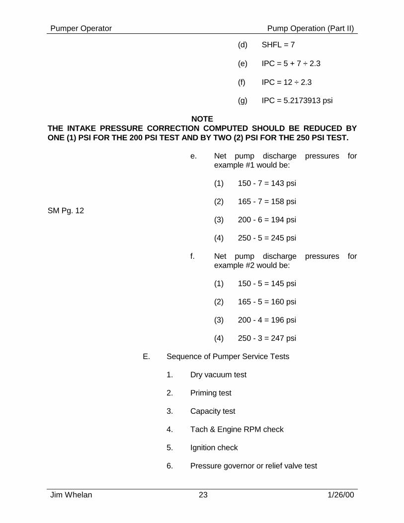
(d) SHFL = 7 (e) IPC = 5 + 7 ÷ 2.3 (f) IPC = 12 ÷ 2.3 (g) IPC = 5.2173913 psi
NOTE THE INTAKE PRESSURE CORRECTION COMPUTED SHOULD BE REDUCED BY ONE (1) PSI FOR THE 200 PSI TEST AND BY TWO (2) PSI FOR THE 250 PSI TEST. e. Net pump discharge pressures for
example #1 would be: (1) 150 - 7 = 143 psi (2) 165 - 7 = 158 psi SM Pg. 12 (3) 200 - 6 = 194 psi (4) 250 - 5 = 245 psi f. Net pump discharge pressures for
example #2 would be: (1) 150 - 5 = 145 psi (2) 165 - 5 = 160 psi (3) 200 - 4 = 196 psi (4) 250 - 3 = 247 psi E. Sequence of Pumper Service Tests 1. Dry vacuum test 2. Priming test 3. Capacity test 4. Tach & Engine RPM check 5. Ignition check 6. Pressure governor or relief valve test

Pumper Operator Pump Operation (Part II)
Jim Whelan 24 1/26/00
7. Overload test 8. 200 PSI test 9. 250 PSI test F. Dry Vacuum Test 1. Checks for air leaks in: a. Priming device b. Pump c. Hard suction hose 2. Steps to follow: a. Drain pump b. Inspect all gaskets (1) suction hose (2) caps (3) fittings c. Inspect suction hose (1) foreign matter (2) loose lining (3) damage threads d. Connect 20' of correct suction hose to
pump intake connection (1) should be same size or larger
than size of intake e. Cap free end of suction hose (1) use cap off pump intake
connection f. Cap all other intake connections

Pumper Operator Pump Operation (Part II)
Jim Whelan 25 1/26/00
g. Remove caps from all discharge ports h. Close all valves (1) drain (2) discharge (3) intake i. Connect vacuum gauge to intake side of
pump
NOTE THE VACUUM GAUGE WILL BE IRREPARABLY DAMAGED IF CONNECTED TO DISCHARGE SIDE OF PUMP. j. Check oil level of primer pump reservoir
(if applicable) k. Make pump packing glands accessible
for inspection (1) raise floorboards (2) open compartment doors (3) other l. Engage priming device until gauge
shows 22" of vacuum developed (1) reduce amount of vacuum by 1"
for every 1000' of elevation m. Compare readings of compound gauge
and test gauge n. If engine is running, shut it off and listen
for air leaks o. No more than 10" of vacuum should be
lost in 10 minutes (1) more than this will affect results of
ensuing tests

Pumper Operator Pump Operation (Part II)
Jim Whelan 26 1/26/00
p. Find and repair any excessive leaks before conducting any further tests
NOTE
IF PUMP PACKING IS A CONTRIBUTING CAUSE TO VACUUM LEAKS, DO NOT TRY TO TIGHTEN IT UP ALL AT ONE TIME. TIGHTENING THE PUMP PACKING GLAND MORE THAN A QUARTER-TURN PER DAY WILL COMPRESS ONLY THE OUTSIDE STRIP OF PACKING, CAUSING IT TO DEFORM AND QUICKLY WEAR OUT. TIGHTENING AT A RATE OF ONE QUARTER TURN PER DAY WILL ALLOW THE ENTIRE PACKING GLAND TO COMPACT AND CREATE A SEAL. q. After successful completion of vacuum
test, prepare engine for remainder of tests
(1) open discharge valve to allow
pressure in pump to equalize (2) replace cap at end of suction hose
with strainer (3) place suction hose and strainer in
water (a) have 2' of water above and
below strainer (4) connect pressure gauge to
discharge side of pump (5) connect adequate number of hose
lines to pump to supply test nozzle (a) test nozzle must be correct
size to handle capacity of pump
(6) secure nozzle
SAFETY NOTE NEVER TRY TO HOLD TEST NOZZLE BY HAND DURING A TEST.
(7) connect pitot tube to test nozzle G. Priming Test 1. Close all valves / petcocks
Pumper Operator Pump Operation (Part II)
Jim Whelan 27 1/26/00
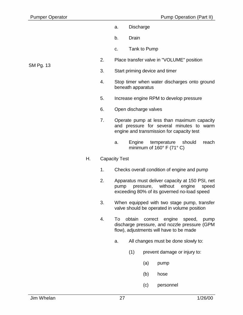
a. Discharge b. Drain c. Tank to Pump 2. Place transfer valve in "VOLUME" position SM Pg. 13 3. Start priming device and timer 4. Stop timer when water discharges onto ground
beneath apparatus 5. Increase engine RPM to develop pressure 6. Open discharge valves 7. Operate pump at less than maximum capacity
and pressure for several minutes to warm engine and transmission for capacity test
a. Engine temperature should reach
minimum of 160° F (71° C) H. Capacity Test 1. Checks overall condition of engine and pump 2. Apparatus must deliver capacity at 150 PSI, net
pump pressure, without engine speed exceeding 80% of its governed no-load speed
3. When equipped with two stage pump, transfer
valve should be operated in volume position 4. To obtain correct engine speed, pump
discharge pressure, and nozzle pressure (GPM flow), adjustments will have to be made
a. All changes must be done slowly to: (1) prevent damage or injury to: (a) pump (b) hose (c) personnel

Pumper Operator Pump Operation (Part II)
Jim Whelan 28 1/26/00
(2) allow resulting pressure changes
to register on gauges 5. Steps to follow: a. After engine is warm, slowly increase
engine speed until pump reaches required discharge pressure (150 PSI), adjusted for:
(1) suction hose friction loss (2) altitude b. Check flow at nozzle, utilizing either: (1) pitot gauge (2) flowmeter c. If flow too great: (1) close down discharge valve (2) readjust (decrease) engine speed
to correct discharge pressure d. If flow too low: (1) open discharge valve further (if
one partially closed) (2) add additional hoseline to
accommodate an increased flow (3) readjust (increase) engine speed
to correct discharge pressure e. When both volume flowing and pump
discharge pressure satisfactory, test officially starts
(1) readings to be taken and recorded
at start of test are: (a) pump discharge pressure

Pumper Operator Pump Operation (Part II)
Jim Whelan 29 1/26/00
(b) nozzle pressure or GPM flow
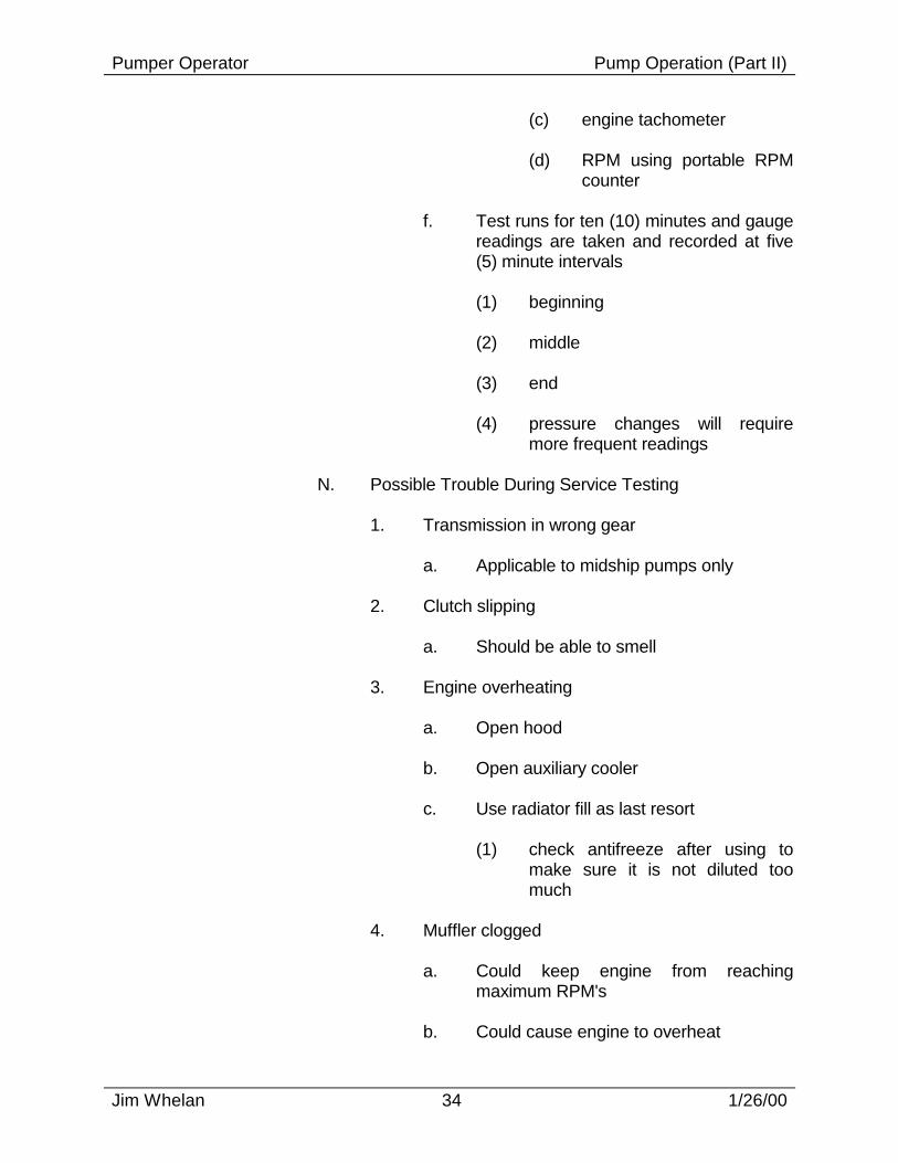
(c) engine tachometer (d) RPM using portable RPM
counter (2) readings should then be taken
and recorded at five (5) minute intervals for twenty (20) minute duration
(a) pressure changes will
require more frequent readings
NOTE
IF A HAND HELD PITOT GAUGE IS BEING USED TO MEASURE THE FLOW PRESSURE, CARE MUST BE TAKEN TO HAVE IT CENTERED IN STREAM WITH THE TIP ONE-HALF THE NOZZLE DIAMETER FROM THE END OF THE NOZZLE. IF THE PITOT IS HELD TOO CLOSE OR TOO FAR AWAY FROM THE END OF THE NOZZLE, THE READING WILL BE INACCURATE. PRESSURE READINGS WILL ALSO BE INACCURATE IF THEY ARE TAKEN FROM THE EDGES OF THE STREAM VERSUS THE CENTER. 6. Items to watch while performing test a. Engine temperature should be kept
within normal limits b. Engine oil pressure should be monitored
to assure proper engine lubrication c. Unusual vibrations in engine or pump
NOTE ANY DEFECTS FOUND IN ENGINE AND/OR PUMP PERFORMANCE SHOULD BE RECORDED. I. Ignition Check
NOTE AN IGNITION TEST IS REQUIRED ONLY OF THOSE VEHICLES HAVING DUAL IGNITION SYSTEMS. 1. During capacity test, isolate and use each
ignition system separately for short time

Pumper Operator Pump Operation (Part II)
Jim Whelan 30 1/26/00
2. Engine speed nor pump discharge pressure
should change substantially J. Pressure Governor or Relief Valve Test 1. Checks units capability to operate at: a. Capacity b. Various pressures SM Pg. 14 2. Should be conducted immediately after capacity
test without: a. Shutting down b. Making any changes in: (1) layout (2) pressure 3. Steps to follow: a. Set pressure control device b. Slowly close all discharge valves c. Record results d. Pump pressure should not increase more
than 30 PSI e. Slowly open all discharge valves and turn
off pressure control device in preparation for overload test
K. Overload Test 1. Determines if engine has any reserve power 2. Apparatus must deliver capacity at 165 PSI, net
pump pressure, without exceeding engines no-load governed speed
3. Conduct immediately after pressure control
device test

Pumper Operator Pump Operation (Part II)
Jim Whelan 31 1/26/00
4. Steps to follow: a. Slowly open throttle to increase engine
speed b. While increasing pump discharge
pressure to 165 PSI, close down valve enough to keep flow at capacity
c. Record results (1) pitot reading (2) pump discharge pressure d. Slowly return engine speed to idle,
closing discharge valves and disengaging pump
L. 200 PSI Test 1. Similar to capacity test 2. Apparatus must deliver 70% of capacity at 200
PSI pump discharge pressure 3. When equipped with two stage pump, consult
certification or acceptance test sheets to determine if transfer valve should be operated in volume or pressure position
4. Steps to follow: a. Slowly increase engine speed until pump
reaches required discharge pressure (200 PSI), adjusted for:
(1) suction hose friction loss (2) altitude b. Check flow at nozzle, utilizing either: (1) pitot gauge (2) flowmeter

Pumper Operator Pump Operation (Part II)
Jim Whelan 32 1/26/00
c. If flow too great: (1) close down discharge valve (2) readjust (decrease) engine speed
to correct discharge pressure d. If flow too low: (1) open discharge valve further (if
one partially closed) (3) readjust (increase) engine speed
to correct discharge pressure e. When both volume flowing and pump
discharge pressure satisfactory, test officially starts
(1) readings to be taken and recorded
at start of test are: (a) pump discharge pressure (b) nozzle pressure or GPM
flow (c) engine tachometer (d) RPM using portable RPM
counter f. Test runs for ten (10) minutes and gauge
readings are taken and recorded at five (5) minute intervals
(1) beginning (2) middle (3) end (4) pressure changes will require
more frequent readings M. 250 PSI Test

Pumper Operator Pump Operation (Part II)
Jim Whelan 33 1/26/00
1. Apparatus must deliver 50% of capacity at 250 PSI pump discharge pressure
SM Pg. 15 2. When equipped with two stage pump, transfer
valve should be operated in pressure position 3. Steps to follow: a. Slowly increase engine speed until pump
reaches required discharge pressure (250 PSI), adjusted for:
(1) suction hose friction loss (2) altitude b. Check flow at nozzle, utilizing either: (1) pitot gauge (2) flowmeter c. If flow too great: (1) close down discharge valve (2) readjust (decrease) engine speed
to correct discharge pressure d. If flow too low: (1) open discharge valve further (if
one partially closed) (3) readjust (increase) engine speed
to correct discharge pressure e. When both volume flowing and pump
discharge pressure satisfactory, test officially starts
(1) readings to be taken and recorded
at start of test are: (a) pump discharge pressure (b) nozzle pressure or GPM
flow
Pumper Operator Pump Operation (Part II)
Jim Whelan 34 1/26/00
(c) engine tachometer (d) RPM using portable RPM
counter f. Test runs for ten (10) minutes and gauge
readings are taken and recorded at five (5) minute intervals
(1) beginning (2) middle (3) end (4) pressure changes will require
more frequent readings N. Possible Trouble During Service Testing 1. Transmission in wrong gear a. Applicable to midship pumps only 2. Clutch slipping a. Should be able to smell 3. Engine overheating a. Open hood b. Open auxiliary cooler c. Use radiator fill as last resort (1) check antifreeze after using to
make sure it is not diluted too much
4. Muffler clogged a. Could keep engine from reaching
maximum RPM's b. Could cause engine to overheat

Pumper Operator Pump Operation (Part II)
Jim Whelan 35 1/26/00
5. Tach inaccurate a. Would give a false reading for
RPM/pressure correlation 6. Engine governor malfunctioning a. Could keep engine from reaching
maximum RPM's b. Possibility of revving past manufacturers
recommended maximum RPM 7. Intake hose too small a. Would not permit enough water flow into
pump 8. Intake strainer submerged wrong a. Could be sucking mud or debris from
bottom b. Could be creating whirlpool and sucking
air from above 9. Intake screens clogged a. Hose strainer could be clogged b. Impeller screen could be plugged 10. Lift too high a. Should be between 5' - 10' 11. Intake hose clogged or lining collapsed a. Difficult to test for collapsed lining (1) Need clear covers for ends of
hose, vacuum pump, and connections
b. If collapsed lining is suspected, try a
different set of suction hoses 12. Air leaks in suction side of pump

Pumper Operator Pump Operation (Part II)
Jim Whelan 36 1/26/00
a. Check all: (1) connections (2) drains (3) packing glands 13. Impellers clogged a. Unless clog is in eye, requires
dismantling of pump 14. Not fully primed a. Small air pockets can keep pump from
priming 15. Relief valve or pressure governor not
functioning a. Might be engaging too soon b. Relief valves should be turned off during
pump tests if possible, to prevent such happenings
16. Inaccurate gauges a. Would give a false reading for
RPM/pressure correlation 17. Transfer valve in wrong position a. Applicable to midship pumps only 18. Partially clogged pitot tube a. Would prevent a true pressure reading SM Pg. 16 19. Nozzle too large a. Would not allow for proper pressures to
be reached 20. Cavitation

Pumper Operator Pump Operation (Part II)
Jim Whelan 37 1/26/00
a. Trying to pump water than available (1) suction hose too small (2) lift too high 21. Leaking fluids a. Fuel b. Oil c. Water d. Small amounts of leakage normal e. Large leaks could endanger apparatus
and/or operator, so tests should be terminated until leaks repaired
22. Vibrations a. Record when it started b. If it continues to get worse, stop test to
correct problem 23. Unusual noises a. Record when it started b. If it continues to get worse, stop test to
correct problem APPLICATION: In this class, we have covered: & SUMMARY: 1. Master streams 2. Dual pumping 3 Tandem pumping 4. Relay pumping 5. Rated pumping capacities 6. Pumper tests to give you the firefighter / engineer a better understanding of how
the fire pump and its components function. Are there any questions?

Pumper Operator Pump Operation (Part II)
Jim Whelan 38 1/26/00
CONCLUSION: If there are no further questions, I will hand out a written test which & requires a minimum score of 70% to pass. We will then go to the drill ASSIGNMENT: ground where we shall put to use the information discussed. All tasks
must be satisfactorily completed to receive credit for this class.
NOTE To become accredited as an Apparatus Operator II by the Department of Public Safety Standards and Training, students must complete task performance evaluations within their own department. These task performances include: 1. Supplying master streams 2. Support a sprinkler system 3. Relay pumping If any students are interested in the accreditation certificate, set a time to meet with them and further explain the program.
Pumper Operator Pump Operation (Part II)
Jim Whelan 1 1/26/00
DRILL GROUND PREPARATIONS FOR PUMP OPERATION II
PRACTICAL EXERCISES

ANNUAL FIRE DEPARTMENT PUMPER SERVICE TEST Test Date: Apparatus #: Year Built: Manufacturer: Mfr. Serial #: ENGINE Make: Model: PUMP Make: Model: Type: SUCTION Size:
Size: Serial #: Capacity: Serial #: Length: Lift: Rated H.P.: Governed RPM: Gear Ratio: Counter Ratio:
TEST DATA CAPACITY TEST (20 min.) 200 PSI TEST (10 min.) 250 PSI TEST (10 min.)
Layout: Nozzle Size: Layout: Nozzle Size: Layout: Nozzle Size:
Time
Counter
RPM Pump
Pressure
Pitot
Vacuum
Time
Counter
RPM Pump
Pressure
Pitot
Vacuum
Time
Counter
RPM Pump
Pressure
Pitot
Vacuum
Totals Totals Totals Avg. Avg. Avg.
Road Gear: Pump Stage: Road Gear: Pump Stage: Road Gear: Pump Stage: Gear Ratio: Engine to Pump: Gear Ratio: Engine to Pump: Gear Ratio: Engine to Pump:
FINAL RESULTS CAP. 200 250 EXCESS POWER TEST (5 min.) DURATION (minutes) GPM @ 165 PSI Net Pump Pressure AVG. PITOT PRESSURE SPEED Engine: RPM Pump: RPM GALLONS PER MINUTE RPM - ENGINE GENERAL REMARKS AND INFORMATION RPM - PUMP Oil Pressure: Engine Temp.: AVG. PUMP PRESSURE Pump took seconds to prime SUCTION PRESSURE Relief Valve Tested: OK NR PUMP STAGE Tested at: Tested by: Witnessed by:

NAME:_______________________________________ DATE:___________________
PUMP CONSTRUCTION AND OPERATION II EVALUATION 1. T F When developing a relay operation, the pumper with the largest
rated capacity should always be used as the attack pumper. 2. T F The amount of water needed and the distance from the water supply
to the fire scene are two critical factors in designing a relay operation.
3. T F If pump packing is too loose, air leaks will affect the pump's ability to
draft water. 4. T F Aligning the transfer valve in a multi-stage centrifugal fire pump to
the SERIES (PRESSURE) position will increase the maximum volume attainable.
5. T F Whenever a multi-stage centrifugal fire pump is used at more than
one-half its rated capacity, the PARALLEL (VOLUME) position should be used.
6. T F Tandem pumping is an operation where a strong hydrant is used to
supply two pumper by connecting the pumpers intake-to-intake. The second pumper receives the excess water not being pumped by the first pumper, which is directly connected to the water supply source.
7. T F Relay pumping is the process of using two or more pumpers to move
water through hoselines over a long distance by operating the pumpers in series.
8. T F When tandem pumping it is possible to create pump discharge
pressures exceeding the pressure to which the fire hose is tested annually.
9. T F The Insurance Services Office (ISO) require that pumper service
tests be conducted yearly. 10. T F When ending a relay pumping operation the initial supply engine
should be shut down first. 11. T F A master stream flowing 1000 gpm has no more nozzle reaction than
a handline flowing 250 gpm. 12. T F Hose lines of unequal sizes and lengths flowing different quantities of
water can create a problem for the apparatus operator. 13. T F Master streams can overload structures and cause early collapse. 14. T F Dual pumping and tandem pumping are the same thing.
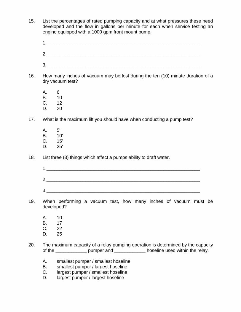
15. List the percentages of rated pumping capacity and at what pressures these need developed and the flow in gallons per minute for each when service testing an engine equipped with a 1000 gpm front mount pump.
1.___________________________________________________________ 2.___________________________________________________________ 3.___________________________________________________________ 16. How many inches of vacuum may be lost during the ten (10) minute duration of a
dry vacuum test? A. 6 B. 10 C. 12 D. 20 17. What is the maximum lift you should have when conducting a pump test? A. 5' B. 10' C. 15' D. 25' 18. List three (3) things which affect a pumps ability to draft water. 1.___________________________________________________________ 2.___________________________________________________________ 3.___________________________________________________________ 19. When performing a vacuum test, how many inches of vacuum must be
developed? A. 10 B. 17 C. 22 D. 25 20. The maximum capacity of a relay pumping operation is determined by the capacity
of the ____________ pumper and ____________ hoseline used within the relay. A. smallest pumper / smallest hoseline B. smallest pumper / largest hoseline C. largest pumper / smallest hoseline D. largest pumper / largest hoseline

ANSWER KEY PUMP CONSTRUCTION AND OPERATION II EVALUATION 1. T F When developing a relay operation, the pumper with the largest
rated capacity should always be used as the attack pumper. 2. T F The amount of water needed and the distance from the water supply
to the fire scene are two critical factors in designing a relay operation.
3. T F If the pump packing is too loose, air leaks will affect the pump's
ability to draft water. 4. T F Aligning the transfer valve in a multi-stage centrifugal fire pump to
the SERIES (PRESSURE) position will increase the maximum volume attainable.
5. T F Whenever a multi-stage centrifugal fire pump is used at more than
one-half its rated capacity, the PARALLEL (VOLUME) position should be used.
6. T F Tandem pumping is an operation where a strong hydrant is used to
supply two pumper by connecting the pumpers intake-to-intake. The second pumper receives the excess water not being pumped by the first pumper, which is directly connected to the water supply source.
7. T F Relay pumping is the process of using two or more pumpers to move
water through hoselines over a long distance by operating the pumpers in series.
8. T F When tandem pumping it is possible to create pump discharge
pressures exceeding the pressure to which the fire hose is tested annually.
9. T F The Insurance Services Office (ISO) require that pumper service
tests be conducted yearly. 10. T F When ending a relay pumping operation the initial supply engine
should be shut down first. 11. T F A master stream flowing 1000 gpm has no more nozzle reaction than
a handline flowing 250 gpm. 12. T F Hose lines of unequal sizes and lengths flowing different quantities of
water can create a problem for the apparatus operator. 13. T F Master streams can overload structures and cause early collapse. 14. T F Dual pumping and tandem pumping are the same thing.
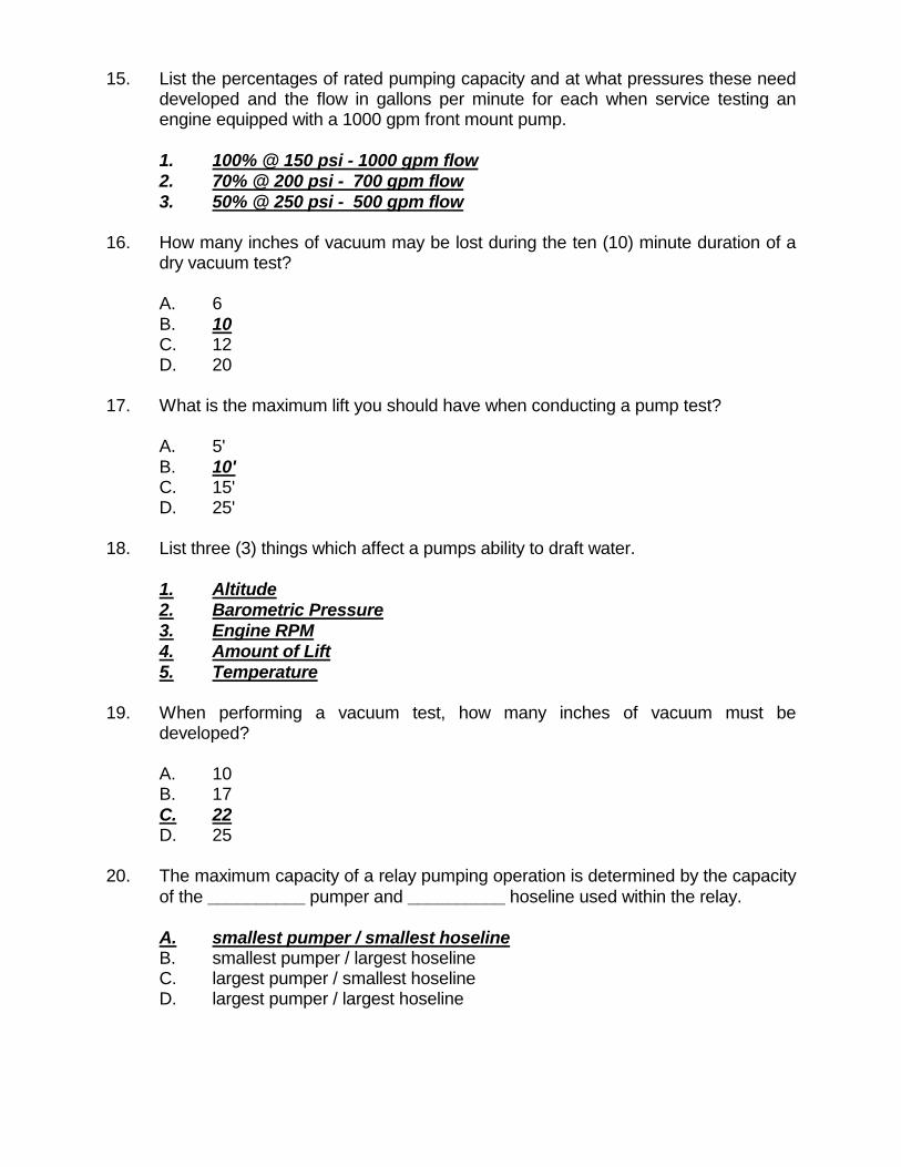
15. List the percentages of rated pumping capacity and at what pressures these need developed and the flow in gallons per minute for each when service testing an engine equipped with a 1000 gpm front mount pump.
1. 100% @ 150 psi - 1000 gpm flow 2. 70% @ 200 psi - 700 gpm flow 3. 50% @ 250 psi - 500 gpm flow 16. How many inches of vacuum may be lost during the ten (10) minute duration of a
dry vacuum test? A. 6 B. 10 C. 12 D. 20 17. What is the maximum lift you should have when conducting a pump test? A. 5' B. 10' C. 15' D. 25' 18. List three (3) things which affect a pumps ability to draft water. 1. Altitude 2. Barometric Pressure 3. Engine RPM 4. Amount of Lift 5. Temperature 19. When performing a vacuum test, how many inches of vacuum must be
developed? A. 10 B. 17 C. 22 D. 25 20. The maximum capacity of a relay pumping operation is determined by the capacity
of the __________ pumper and __________ hoseline used within the relay. A. smallest pumper / smallest hoseline B. smallest pumper / largest hoseline C. largest pumper / smallest hoseline D. largest pumper / largest hoseline

1
STUDENT MANUAL PUMP OPERATION (Part II)
STANDARD: NFPA 1002 (1998 Edition) REFERENCE: IFSTA "Fire Department Pumping Apparatus", 7th Edition OBJECTIVES: At the end of this class, the apparatus operator shall: 1. Identify the percentages of rated capacity, rated
pressures, and the capacity in gallons per minute at the rated pressures a fire department pumper is designed to deliver.
2. Demonstrate production of effective master streams, using multiple lines.
3. Demonstrate procedures for the following: a. relay pumping b. tandem pumping c. dual pumping d. taking over a hydrant 4. Demonstrate procedures for conducting an annual
pump test. I. MASTER STREAMS A. Definition of (IFSTA): 1. "Any of a variety of heavy, large-caliber water streams; usually
supplied by siamesing two or more hoselines into a manifold device capable of delivering a minimum of 350 gpm."
B. Three (3) Main Uses C. Placement 1. Must be properly placed before being put in service 2. When operating through door or window, place appliance close
enough to reach seat of fire 3. Stream should enter structure at upward angle 4. Place appliance to optimize stream coverage

2
D. Supplying 1. Flows large volumes of water which can generate large amount of
friction loss 2. Supply hose bed loads should be set up for dual lay to reduce set-up
time E. Safety
SAFETY NOTE A MASTER STREAM FLOWS A LARGE VOLUME OF WATER WHICH CREATES SUBSTANTIAL ENERGY. THE NOZZLE REACTION PRODUCED BY THE DISCHARGE STREAM CAN BE EXTREMELY POWERFUL. CARE MUST BE TAKEN DURING THE OPERATION OF THESE MASTER STREAMS TO INSURE THEY DO NOT INJURE SOMEONE. ALL PERSONNEL SHOULD BE FAMILIAR WITH THE OPERATION OF MASTER STREAMS AS USED BY THEIR RESPECTIVE FIRE DEPARTMENTS. 1. Never direct master streams into occupied areas 2. Prevent personnel from walking into streams 3. When flowing portable master stream, follow basic guidelines: a. Maintain ground spikes b. Keep hoselines straight behind inlet for minimum of 10' c. Before flowing: d. Do not:: II. DUAL PUMPING A. Definition of (IFSTA): 1. "An operation where a strong hydrant is used to supply two pumpers
by connecting the pumpers intake-to-intake. The second pumper receives the excess water not being pumped by the first pumper, which is directly connected to the water supply source."

3
B. Advantages 1. Better use of water supply 2. Additional hoselines may be placed into operation faster 3. Improved coordination C. Procedure 1. First pumper connects to hydrant steamer port using large diameter
suction 2. This pumper starts to supply water to incident 3. Second pumper positioned intake-to-intake with first pumper 4. Water supply to first pumper restricted until residual pressure on
compound gauge reads near zero (5 psi approx.) 5. Throttle of first pumper may need adjusting 6. Intake water volume now equal to discharge water volume, allowing
removal of unused intake cap 7. Second pumper connected to unused steamer intake of first pumper
with large diameter suction 8. Water supply fully restored to first pumper 9. Second pumper supplies water to incident III. TANDEM PUMPING A. Definition of (IFSTA): 1. "A short relay operation in which the pumper taking water from the
supply source pumps into the intake of the second pumper. The second pumper boosts the pressure of the water even higher. This method is used when pressures higher than the capability of a single pump are required."
B. Commonly used when attack pumper located close to hydrant and needs to
overcome friction loss problems which occur in: 1. Large sprinkler or standpipe systems 2. Long hose lays

4
C. Procedure 1. Pumper directly connected to water supply pumps through its
discharge outlet(s) into intake(s) of second engine 2. Pumpers generally not over 300 feet apart
SAFETY NOTE IN TANDEM PUMPING OPERATIONS IT IS POSSIBLE TO SUPPLY PRESSURES GREATER THAN THE HOSELINES CAN WITHSTAND. THE PRESSURE DEVELOPED SHOULD NEVER EXCEED THE PRESSURE TO WHICH THE HOSE IS ANNUALLY TESTED. IV. TAKING OVER A HYDRANT A. Procedure used to overcome friction loss encountered when trying to: B. Engine taking over hydrant: 1. Responsible for overcoming friction loss in supply line 2. Not responsible for providing hose lines or fire streams for fire attack C. Procedure 1. First in engine (Engine 1) stops at hydrant and drops two (2) lines 2. Connect "wet" line with gate valve to one side of hydrant and second
gate valve to appropriate preplanned hydrant discharge port 3. Turn on hydrant, charging "wet" line, when engineer ready for water 4. Second in engine (Engine 2) spots apparatus to pump from hydrant 5. Engine 2 connects:

5
6. "Dry" line charged after getting approval from Engine 1 7. Engine 2 notifies Engine 1 they are shutting down hydrant ("wet") line 8. Engine 2: D. Variation 1. Engine 1 connects to hydrant with one (1) supply line and proceeds
as normal 2. Upon realizing they need more water they ask Engine 2 to supply it 3. Engine 2 makes a reverse lay, dropping required number of lines to
flow volume of water Engine 1 needs 4. Engine 2:
SAFETY NOTE THE TRANSITION FROM TANK WATER TO HYDRANT WATER MUST HAPPEN BEFORE THE TANK WATER IS DEPLETED. FAILURE TO DO SO COULD BE DISASTROUS. V. RATED PUMPING CAPACITIES A. Capacity 1. Definition of (for this class): a. "The volume of water that a pump can discharge from a static
source draft at a certain pressure each minute" B. Rated Capacity is: 1. One means of identifying pump capabilities 2. Determined by testing 3. Not necessarily maximum capacity of pump 4. Actual capacity of centrifugal pumps limited by design features

6
5. Capacity of positive displacement pump limited by 6. To pass test and be rated, fire pumps must meet following capacity
and pressure requirements: a. 100% of rated capacity @ 150 PSI b. 70% of rated capacity @ 200 PSI c. 50% of rated capacity @ 250 PSI 7. Insurance Services Office requires pumps be tested annually VI. RELAY PUMPING A. Definition of (IFSTA): 1 "The process of using two or more pumpers to move water through
hoselines over a long distance by operating the pumpers in series." B. Requirements 1. Relay operations dependent on: C. Limitations 1. Rated pump capacities 2. Pressure restrictions demanded by use of fire hose D. Designing Relay Operations 1. Formula to determine number of pumpers needed to relay specific
quantity of water
TPN = RD ÷÷÷÷ TD +1

7
MAXIMUM DISTANCE OF WATER FLOW AT 180 PSI(in feet)
Flow Hose Diameter (inches) in GPM 2 1/2 3 4 5 6 100 9,000 22,500 90,000 225,000 360,000 200 2,250 5,625 22,500 56,200 90,000 250 1,440 3,600 14,400 36,000 57,600 300 1,000 2,500 10,000 25,000 40,000 400 563 1,406 5,625 14,060 22,500 500 360 900 3,600 9,000 14,000 750 160 400 1,600 4,000 6,400 1000 90 225 900 2,250 3,600
2. How many pumpers would be required to run 500 gpm, 1000 ft.,
using 2 1/2" hose? 3. How many pumpers would be required to run 750 gpm, 700 ft., using
3" hose? 4. How many pumpers would be required to run 1000 gpm, 1800 ft.,
using a double lay of 3" hose? 5. How many pumpers would be required to run 1000 gpm, 4500 ft.,
using 5" hose? 6. Largest capacity pumper should be located at water supply E. Starting Relay Operations 1. Initial or source pumper establishes water supply, dumping water
through dump line until next pumper in relay ready 2. On command, source pumper slowly:
SAFETY NOTE

8
VALVES SHOULD BE OPENED SLOWLY TO PREVENT WATER HAMMER. 3. Relay operator should: 4. Relay established once relay pumper reaches calculated pressure
with dump line flowing, further adjustments should not be necessary 5. Follow same basic procedure to supply second relay pumper 6. First relay operator should slowly: 7. Second relay operator receives and sends water exactly as did first
relay operator and so on down line 8. This procedure followed until water reaches attack pumper 9. Operator of attack pumper should:
SAFETY NOTE ANY NEGLIGENCE BY THE OPERATOR TO NOT CONNECT THE DUMP LINE AND/OR MONITOR PUMP DISCHARGE PRESSURE COULD LEAD TO DANGEROUS PRESSURE BUILDUP IN RELAY AND/OR ATTACK LINES. 10. Relay operators should set relief valve(s), both intake and discharge,
and / or pressure governor as soon as relay flowing water and fully operational
11. Use of automatic pressure control devices necessary to compensate
for fluctuations in pressure caused by changes in flow F. Ending Relay Operations 1. Fire attack pumper should be shut down first 2. Starting with attack pumper, each operator should:

9
SAFETY NOTE EFFECTIVE COMMUNICATIONS ARE ESSENTIAL TO AN EFFICIENT RELAY PUMPING OPERATION. FIREFIGHTER SAFETY COULD BE AT RISK IF RELAY OPERATION NOT COORDINATED. VII. PUMPER TESTS A. Three Kinds 1. Certification 2. Acceptance 3. Service B. Certification Test 1. Assures pump performance and tank-to-pump flow rates meet NFPA
1901 requirements 2. Conducted by Underwriters Laboratories (UL) 3. Generally done at site of manufacture 4. Consists of: C. Acceptance Test 1. Assures purchaser that apparatus meets bid specifications 2. Usually conducted by purchaser with manufacturer's representative
present 3. Most often performed after apparatus has been delivered to
purchaser, but before acceptance 4. Apparatus can be rejected if it fails to achieve requirements detailed
in bid specifications 5. Consists of:

10
D. Service Test 1. Assures apparatus engine and pump perform as required 2. Conducted regularly 3. Factors affecting test 4. Net Pump Discharge Pressure
NOTE NET PUMP DISCHARGE PRESSURE (NPDP), AS DEFINED IN IFSTA "PUMPING APPARATUS", IS THE TOTAL WORK DONE BY THE PUMP TO GET THE WATER INTO, THROUGH, AND OUT OF THE PUMP. WHEN TAKING WATER FROM A HYDRANT, IT IS THE DIFFERENCE BETWEEN THE INTAKE PRESSURE AND THE DISCHARGE PRESSURE. WHEN DRAFTING, IT IS THE SUM OF THE PUMP DISCHARGE PRESSURE AND THE INTAKE HOSE ALLOWANCE (INTAKE PRESSURE CORRECTION).
FRICTION LOSS ALLOWANCES FOR INTAKE HOSE
Rated Pump Cap. Hose Dia. Allowance (feet) (U.S. GPM) (inches) For 10’ of Hose Each Additional 10’
500
4 4 1/2
6 3 1/2
+1 + 1/2
750
4 1/2 5
7 4 1/2
+1 1/2 +1
1000
4 1/2 5 6
13 8 4
+2 +1 1/2 + 1/2
1250
5 6
12 1/2 6 1/2
+2 + 1/2
1500 6 9 +1 IPC = L + SHFL ÷ 2.3 IPC is intake pressure (in psi) L is lift (in feet) SHFL is suction hose friction loss

11
Example #1: Conducting test on 750 gpm pumper using 20' of 4 1/2"
suction hose with a 7' lift IPC = L + SHFL ÷ 2.3 L = 7 SHFL = 7 + 1.5 SHFL = 8.5 IPC = 7 + 8.5 ÷ 2.3 IPC = 15.5 ÷ 2.3 IPC = 6.7391304 psi Example #2: Conducting test on 1250 gpm pumper using 20' of 6" suction
hose with a 5' lift IPC = L + SHFL ÷ 2.3 L = 5 SHFL = 6.5 + .5 SHFL = 7 IPC = 5 + 7 ÷ 2.3 IPC = 12 ÷ 2.3 IPC = 5.2173913 psi
NOTE THE INTAKE PRESSURE CORRECTION COMPUTED SHOULD BE REDUCED BY ONE (1) PSI FOR THE 200 PSI TEST AND BY TWO (2) PSI FOR THE 250 PSI TEST. Net pump discharge pressures for example #1 would be: 150 - 7 = 143 psi 165 - 7 = 158 psi 200 - 6 = 194 psi

12
250 - 5 = 245 psi Net pump discharge pressures for example #2 would be: 150 - 5 = 145 psi 165 - 5 = 160 psi 200 - 4 = 196 psi 250 - 3 = 247 psi E. Sequence of Pumper Service Tests 1. Dry vacuum test 2. Priming test 3. Capacity test 4. Tach & Engine RPM check 5. Ignition check 6. Pressure governor or relief valve test 7. Overload test 8. 200 PSI test 9. 250 PSI test F. Dry Vacuum Test 1. Checks for air leaks in: 2. Steps to follow: G. Priming Test 1. Close all valves / petcocks 2. Place transfer valve in "VOLUME" position 3. Start priming device and timer

13
4. Stop timer when water discharges onto ground beneath apparatus 5. Increase engine RPM to develop pressure 6 Open discharge valves 7. Operate pump at less than maximum capacity and pressure for
several minutes to warm engine and transmission for capacity test H. Capacity Test 1. Checks overall condition of engine and pump 2. Apparatus must deliver capacity at 150 PSI, net pump pressure,
without engine speed exceeding 80% of its governed no-load speed 3. When equipped with two stage pump, transfer valve should be
operated in volume position 4. To obtain correct engine speed, pump discharge pressure, and
nozzle pressure (GPM flow), adjustments will have to be made 5. Steps to follow: 6. Items to watch while performing test: I. Ignition Check 1. During capacity test, isolate and use each ignition system separately
for short time 2. Engine speed nor pump discharge pressure should change
substantially J. Pressure Governor or Relief Valve Test 1. Checks units capability to operate at: 2. Should be conducted immediately after capacity test without:

14
3. Steps to follow: K. Overload Test 1. Determines if engine has any reserve power 2. Apparatus must deliver capacity at 165 PSI, net pump pressure,
without exceeding engines no-load governed speed 3. Conduct immediately after pressure control device test 4. Steps to follow: L. 200 PSI Test 1. Similar to capacity test 2. Apparatus must deliver 70% of capacity at 200 PSI pump discharge
pressure 3 When equipped with two stage pump, consult certification or
acceptance test sheets to determine if transfer valve should be operated in volume or pressure position
4. Steps to follow: M. 250 PSI Test 1. Apparatus must deliver 50% of capacity at 250 PSI pump discharge
pressure

15
2. When equipped with two stage pump, transfer valve should be operated in pressure position
3. Steps to follow: N. Possible Trouble During Service Testing 1. Transmission in wrong gear 2. Clutch slipping 3. Engine overheating 4. Muffler clogged 5. Tach inaccurate 6. Engine governor malfunctioning 7. Intake hose too small 8. Intake strainer submerged wrong 9. Intake screens clogged 10. Lift too high 11. Intake hose clogged or lining collapsed 12. Air leaks in suction side of pump 13. Impellers clogged 14. Not fully primed 15. Relief valve or pressure governor not functioning 16 Inaccurate gauges 17. Transfer valve in wrong position 18. Partially clogged pitot tube 19. Nozzle too large

16
20. Cavitation 21. Leaking fluids 22. Vibrations 23. Unusual noises

ANNUAL FIRE DEPARTMENT PUMPER SERVICE TEST Test Date: Apparatus #: Year Built: Manufacturer: Mfr. Serial #: ENGINE Make: Model: PUMP Make: Model: Type: SUCTION Size:
Size: Serial #: Capacity: Serial #: Length: Lift: Rated H.P.: Governed RPM: Gear Ratio: Counter Ratio:
TEST DATA CAPACITY TEST (20 min.) 200 PSI TEST (10 min.) 250 PSI TEST (10 min.)
Layout: Nozzle Size: Layout: Nozzle Size: Layout: Nozzle Size:
Time
Counter
RPM Pump
Pressure
Pitot
Vacuum
Time
Counter
RPM Pump
Pressure
Pitot
Vacuum
Time
Counter
RPM Pump
Pressure
Pitot
Vacuum
Totals Totals Totals Avg. Avg. Avg.
Road Gear: Pump Stage: Road Gear: Pump Stage: Road Gear: Pump Stage: Gear Ratio: Engine to Pump: Gear Ratio: Engine to Pump: Gear Ratio: Engine to Pump:
FINAL RESULTS CAP. 200 250 EXCESS POWER TEST (5 min.) DURATION (minutes) GPM @ 165 PSI Net Pump Pressure AVG. PITOT PRESSURE SPEED Engine: RPM Pump: RPM GALLONS PER MINUTE RPM - ENGINE GENERAL REMARKS AND INFORMATION RPM - PUMP Oil Pressure: Engine Temp.: AVG. PUMP PRESSURE Pump took seconds to prime SUCTION PRESSURE Relief Valve Tested: OK NR PUMP STAGE Tested at: Tested by: Witnessed by: