Embed Size (px)
Citation preview
1
Rekluse Motor Sports
The z-Start Clutch
LTR 450
Installation Guide
Copyright 2002 Rekluse Motor Sports z-Start Revision 3.000 RMS166 – LTR 450
191-266
Manual Revision: 032306
Rekluse Motor Sports, inc.
110 E. 43rd Street
Boise, Idaho 83714
208-426-0659

2
Required Tools
8mm socket 1/4 inch driver (for included Torx T10 driver tip) 10mm socket 2 Sets of feeler gauges 5mm allen key Inch Pound Torque Wrench 4mm allen key socket Torx T10 driver tip (included) 3mm allen Blue Loctite 243 (oil resistant)
z-Start Overview
Note: The Lower Assembly is packaged underneath the Pressure Plate and held in place with two screws through the Top Plate.

3
Included Parts for the z-Start Clutch
Note: spare screws, balls and shims may be included with your clutch
Top Plate 2" (51mm) Wave Spring (CS200L1)
Pressure Plate 12 x M3 #10 torx screws Lower Assembly 30 x 3/8" (9.53mm) balls 4 x .047 (1.2mm) Drive Plates 5 x 3/8" (9.53mm) Tungsten Carbide (TC) balls
7/32” (5.56-mm) Ball Spacer 1 x .055 (1.4mm) Drive Plate – for wear adjustment
Clutch Throw-out Rekluse Perch Adjuster
½” (12.7mm) Throw-out Needle Thrust Bearing 2 Clutch Cover Gaskets ½” (12.7mm) Flat Throw-out Thrust Washer 6 x M6 Flat Head Screws
Basic z-Start Clutch Operation The z-Start Auto Clutch functions through centrifugal force. As engine RPM increases, the balls contained in the z-Start Pressure Plate travel up the ball ramps and push against the Top Plate. This action forces the Pressure Plate to engage the clutch pack.
Installation Tips In order for the z-Start Clutch to perform properly, it must be mounted properly. • Measuring and maintaining the Installed Gap is critical. If the Installed Gap is too big the clutch will slip
excessively and cause rapid clutch wear. If the Installed Gap is too small, the clutch will drag and cause engine stall.
• Recognize that the Pressure Plate travels along the tabs of the Lower Assembly as it engages and disengages. Anything preventing this travel will prevent full engagement and cause the clutch to slip excessively.
• Since you will be installing the Rekluse Perch Adjuster as a manual override for your z-Start Clutch, it is critical to have the cable slack adjusted properly. First complete the installation of the z-Start Clutch using this manual and ensure proper installed gap. Then refer to the Rekluse Perch Adjuster manual to ensure proper cable slack adjustment.
• Be very careful not to drop any screws, washers, balls, or springs into the crankcase opening! It is surprisingly easy to drop a little screw or washer down into your crankcase. It is not always so easy to get it out. Make sure all parts going in and coming out are accounted for before you finish the installation. A strong magnetic probe can often be used to retrieve little parts if you happen to drop something in.
4
Bike Preparation and Disassembly
1. Disconnect your clutch cable at your clutch lever.
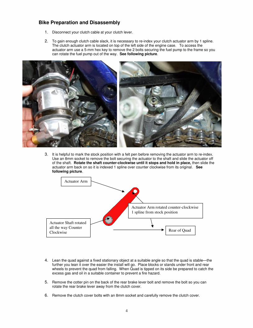
2. To gain enough clutch cable slack, it is necessary to re-index your clutch actuator arm by 1 spline. The clutch actuator arm is located on top of the left side of the engine case. To access the actuator arm use a 5-mm hex key to remove the 2 bolts securing the fuel pump to the frame so you can rotate the fuel pump out of the way. See following picture.
3. It is helpful to mark the stock position with a felt pen before removing the actuator arm to re-index. Use an 8mm socket to remove the bolt securing the actuator to the shaft and slide the actuator off of the shaft. Rotate the shaft counter-clockwise until it stops and hold in place, then slide the actuator arm back on so it is indexed 1 spline over counter clockwise from its original. See following picture.
4. Lean the quad against a fixed stationary object at a suitable angle so that the quad is stable—the further you lean it over the easier the install will go. Place blocks or stands under front and rear wheels to prevent the quad from falling. When Quad is tipped on its side be prepared to catch the excess gas and oil in a suitable container to prevent a fire hazard.
5. Remove the cotter pin on the back of the rear brake lever bolt and remove the bolt so you can rotate the rear brake lever away from the clutch cover.
6. Remove the clutch cover bolts with an 8mm socket and carefully remove the clutch cover.
Rear of Quad
Actuator Arm
Actuator Shaft rotated
all the way Counter
Clockwise
Actuator Arm rotated counter-clockwise
1 spline from stock position
5
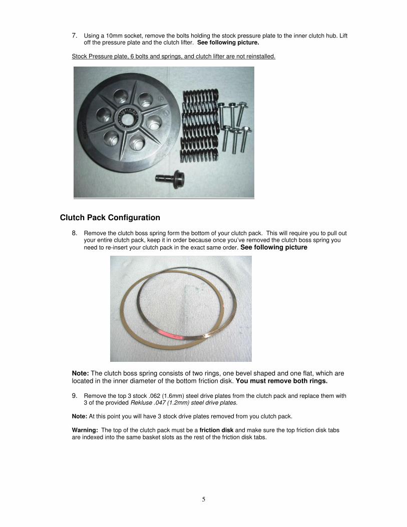
7. Using a 10mm socket, remove the bolts holding the stock pressure plate to the inner clutch hub. Lift off the pressure plate and the clutch lifter. See following picture.
Stock Pressure plate, 6 bolts and springs, and clutch lifter are not reinstalled.
Clutch Pack Configuration
8. Remove the clutch boss spring form the bottom of your clutch pack. This will require you to pull out your entire clutch pack, keep it in order because once you’ve removed the clutch boss spring you
need to re-insert your clutch pack in the exact same order. See following picture
Note: The clutch boss spring consists of two rings, one bevel shaped and one flat, which are located in the inner diameter of the bottom friction disk. You must remove both rings.
9. Remove the top 3 stock .062 (1.6mm) steel drive plates from the clutch pack and replace them with 3 of the provided Rekluse .047 (1.2mm) steel drive plates.
Note: At this point you will have 3 stock drive plates removed from you clutch pack. Warning: The top of the clutch pack must be a friction disk and make sure the top friction disk tabs are indexed into the same basket slots as the rest of the friction disk tabs.
6
Installing the Lower Assembly
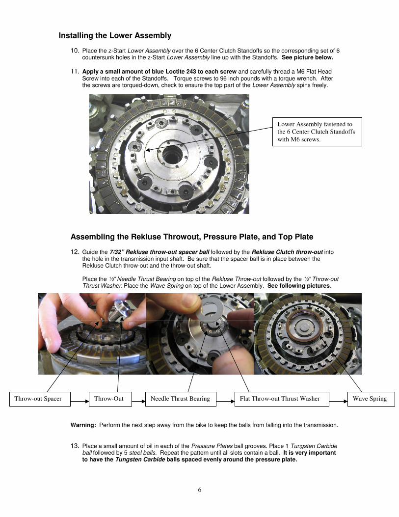
10. Place the z-Start Lower Assembly over the 6 Center Clutch Standoffs so the corresponding set of 6 countersunk holes in the z-Start Lower Assembly line up with the Standoffs. See picture below.
11. Apply a small amount of blue Loctite 243 to each screw and carefully thread a M6 Flat Head Screw into each of the Standoffs. Torque screws to 96 inch pounds with a torque wrench. After the screws are torqued-down, check to ensure the top part of the Lower Assembly spins freely.
Assembling the Rekluse Throwout, Pressure Plate, and Top Plate
12. Guide the 7/32” Rekluse throw-out spacer ball followed by the Rekluse Clutch throw-out into the hole in the transmission input shaft. Be sure that the spacer ball is in place between the Rekluse Clutch throw-out and the throw-out shaft. Place the ½” Needle Thrust Bearing on top of the Rekluse Throw-out followed by the ½” Throw-out Thrust Washer. Place the Wave Spring on top of the Lower Assembly. See following pictures.
Warning: Perform the next step away from the bike to keep the balls from falling into the transmission.
13. Place a small amount of oil in each of the Pressure Plates ball grooves. Place 1 Tungsten Carbide ball followed by 5 steel balls. Repeat the pattern until all slots contain a ball. It is very important to have the Tungsten Carbide balls spaced evenly around the pressure plate.
Lower Assembly fastened to
the 6 Center Clutch Standoffs
with M6 screws.
Throw-Out Flat Throw-out Thrust Washer Needle Thrust Bearing Wave Spring Throw-out Spacer

7
14. Place the Pressure Plate with the 30 Balls in place over the z-Start Lower Assembly. Index the outer tabs of the Pressure Plate into the windows of the clutch basket. The outer tabs of the Pressure Plate must rest in the same clutch basket windows that the outer tabs of the friction disks do.
Also insure that the tabs of the Lower Assembly pass through the associated cut-outs in the Pressure Plate. Make sure the top of the Rekluse Throw-out assembly passes through the hole in the center of the z-Start Pressure Plate. See following picture.
15. With a felt pen, mark three of the holes evenly spaced around the top plate. While holding the Pressure Plate down place the Top Plate over the Pressure Plate and fasten it to the tabs of the Lower Assembly with three of the M3 screws, through the three marked holes in the Top Plate. Lightly tighten each screw using a 1/4 inch driver and the included Torx T10 driver tip. See following picture.
Note: You will have to overcome the z-Start Wave Spring and hold the Pressure Plate down until the 3 screws are securely fastened in order to tighten the Top Plate down properly.
Tabs Passing through
Pressure Plate.
Holding down Pressure Plate
until Top Plate is securely
fastened.
Throw-out assembly
passing through
center of Pressure
Plate.

8
Determine the installed gap of the Z-Start
16. Measure the installed gap of the z-Start. Two sets of feeler gauges are required to measure the Installed Gap. The feeler gauges must be placed between the top most friction disk and the top-most steel drive plate in the clutch pack 180 degrees apart. See following pictures. Note: Insert the 2 sets of feeler gauges directly across from one another (180 degrees apart) to avoid the clutch pack from rocking resulting in an inaccurate measurement. Find the thickest feeler gauge that still slides back and forth with slight resistance.
The installed gap should be between .030” (0.76mm) and .042” (1.07mm). If the gap is correct, move on to the next step. If the installed gap measurement is off, then the installed gap needs to be adjusted due to manufacturing variances in the bike’s center clutch. If the measurement is greater than .042” replace one Rekluse .047” (1.2mm) drive plate with a stock .062 (1.6mm) drive plate. If the measurement is less than.029” replace one stock .062 (1.6mm) drive plate with a Rekluse .047 (1.2mm) drive plate. Note: 1 x .055” Drive Plate is included to make finer wear adjustments between stock and Rekluse .047” drive plates. Note: Be sure to review the included Break-in and Maintenance Guide for clutch pack wear adjustments.
Final Installation Steps Note: Use 243 Loctite (Blue, oil resistant) to secure all M3 Torx screws
17. Using a small amount of Blue Loctite 243, install the rest of the M3 torx head screws and torque to 10 inch/pounds. 10 inch-pounds requires a good crank with the included Torx T10 driver tip, but be careful not to bend the head of the T10 driver tip. Remove the three marked M3 screws, add Loctite, and tighten.
18. Re-install your clutch cover with the 2 included Rekluse Clutch Cover Gaskets. Hand-tighten each of the clutch cover bolts, then torque to 6 foot/pounds in 2 steps.
Warning: Both Rekluse gaskets must be used or considerable clutch damage will result.
19. Refer to the included z-Start External Perch Adjuster instructions to complete the installation.
WARNING: After a 20 minute break-in period, the clutch plates will seat in and you must re-measure the Installed Gap to guarantee the Installed Gap is within the prescribed range—make drive plate adjustments if necessary. See step 17. Clutch break-in re-measurement of the Installed Gap is necessary whenever new clutch plates are installed.


![[XLS] · Web view450. 90. 450. 900. 900. 225. 450. 450. 900. 450. 225. 270. 4.5. 450. 450. 450. 450. 450. 450. 450. 450. 450. 900. 450. 450. 450. 112.5. 900. 900. 450. 112.5. 450](https://img.dokumen.tips/doc/110x75/5b3c17127f8b9a213f8d0b42/xls-web-view450-90-450-900-900-225-450-450-900-450-225-270-45.jpg)