Embed Size (px)
Citation preview
ReinforcingBar Couplersfor the Construction Industry
CI/SfB (29) Et6
June 2014
UK & Ireland Edition
2 Tel: +44 (0) 114 275 5224 www.ancon.co.uk
Coupler Selection 4-5
Tapered Thread Standard Series 6-7
Tapered Thread Positional Series 8-9
Tapered Thread Transition Series 10
Tapered Thread Weldable Couplers 11
Tapered Thread Headed Anchors 12
Accessories 12
BT Stainless Steel Couplers 13
Bartec Plus Types A, B & C 14-16
Bartec Plus Transition Couplers 17-19
Bartec Plus Headed Anchors 20
Bartec Plus Weldable Anchors 21
MBT ET Series 22-23
MBT Transition Series 24
MBT Continuity C Series 25
MBT Headed Anchors 26
Grout Sleeve Couplers 27
Other Ancon Products 27
Contents
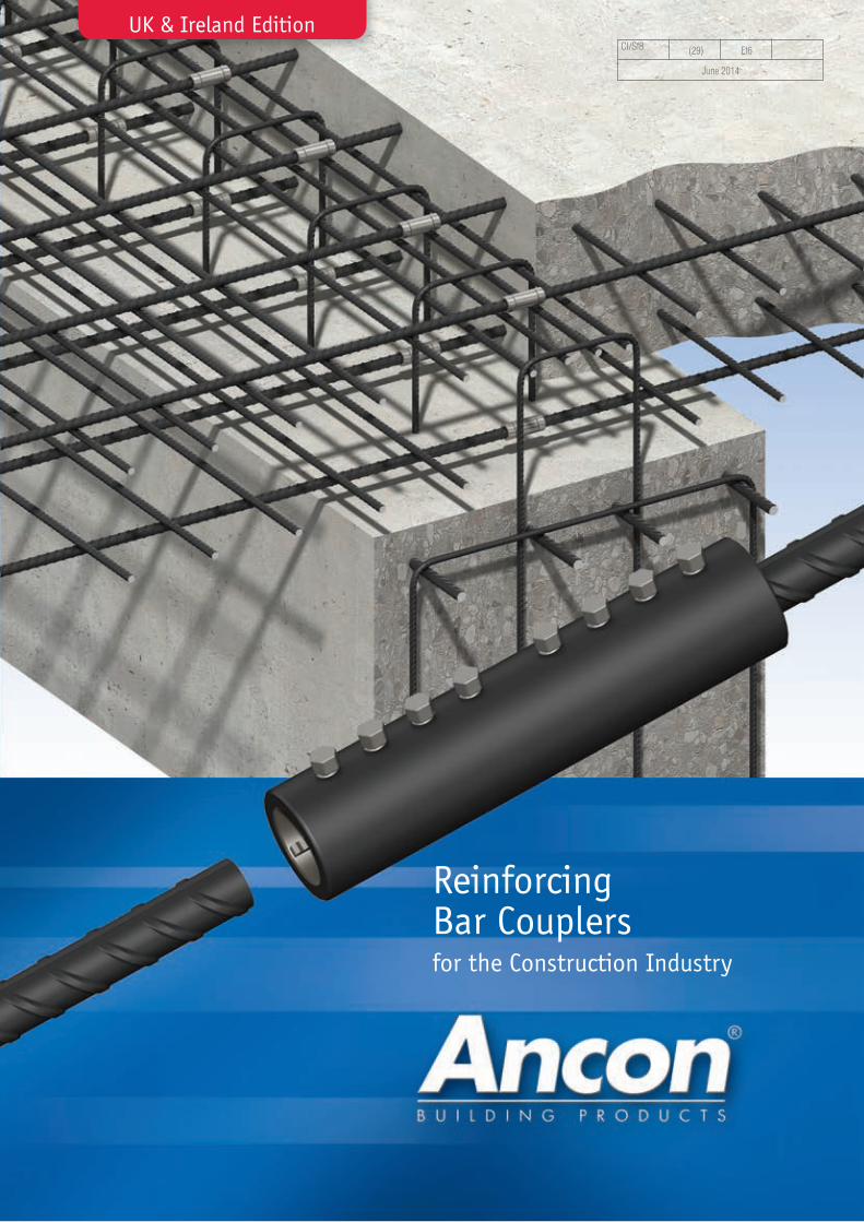
Lapped joints are not always anappropriate means of connectingreinforcing bars. The use of lapscan be time consuming in termsof design and installation andcan lead to greater congestionwithin the concrete because ofthe increased amount of rebarused.
Ancon couplers can simplify thedesign and construction ofreinforced concrete and reducethe amount of reinforcementrequired.
Lapped joints are dependentupon the concrete for loadtransfer. For this reason anydegradation in the integrity of
the concrete could significantlyaffect the performance of thejoint. The strength of amechanical splice is independentof the concrete in which it islocated and will retain itsstrength despite loss of cover asa result of impact damage orseismic event.
The Ancon range of reinforcingbar couplers is the mostcomprehensive available andincludes tapered threaded,parallel threaded, mechanicallybolted and grouted couplers.Stainless steel couplers complete the range.
Reinforcing Bar CouplersSimplify the design and construction of concrete

3
Comprehensive Range Eurocode 2 compliant Simplify design andconstruction
Reduce amount ofreinforcement required
Dedicated salessupport
Technical approvalTA1-B 5015 for
Tapered Thread Couplers
Available through majorrebar stockists and
approved distributors
Technical approvalTA1-A 5050 for
Bartec Plus Couplers
ISO 9001, ISO 14001,OHSAS 18001
BBA Approvalfor
MBT ET Couplers
Refer to the approval reports for coupler sizes and types covered.
Reinforcing Bar Couplers
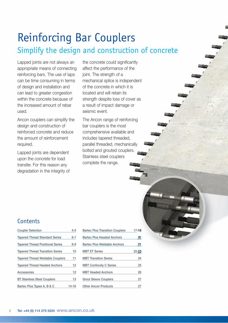
Tapered Thread (pages 6-12)The Tapered Thread coupler is designed to suitthe majority of applications which require thejoining of reinforcing bars. The ends of the rebar are cut square and a tapered thread is cutonto the bar to suit the tapered thread coupler.The sleeve is tightened onto the threaded barend using a calibrated torque wrench.
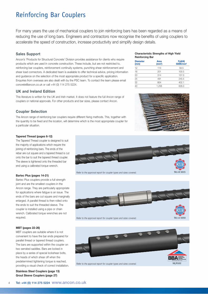
MBT (pages 22-26)MBT couplers are suitable where it is notconvenient to have the bar ends prepared forparallel thread or tapered thread couplers.The bars are supported within the coupler ontwo serrated saddles. Bars are locked inplace by a series of special lockshear bolts,the heads of which shear off when thepredetermined tightening torque is reached,providing a visual check of correct installation.
Stainless Steel Couplers (page 13)Grout Sleeve Couplers (page 27)
Bartec Plus (pages 14-21)Bartec Plus couplers provide a full strengthjoint and are the smallest couplers in theAncon range. They are particularly appropriatefor applications where fatigue is an issue. Theends of the bars are cut square and marginallyenlarged. A parallel thread is then rolled ontothe ends to suit the threaded sleeve. Thecoupler is installed using a pipe or chainwrench. Calibrated torque wrenches are notrequired.
Sales SupportAncon’s ‘Products for Structural Concrete’ Division provides assistance for clients who requireproducts which are used in concrete construction. These include, but are not restricted to,reinforcing bar couplers, reinforcement continuity systems, punching shear reinforcement andshear load connectors. A dedicated team is available to offer technical advice, pricing informationand guidance on the selection of the most appropriate product for a specific application.Enquiries from overseas are also dealt with by the PSC team. To contact the team please [email protected] or call +44 (0) 114 275 5224.
UK and Ireland EditionThis literature is written for the UK and Irish market. It does not feature the full Ancon range ofcouplers or national approvals. For other products and bar sizes, please contact Ancon.
Characteristic Strengths of High YieldReinforcing BarDiameter Area Fy(kN)(mm) (mm2) 500N/mm2
12 113 56.5
16 201 100.5
20 314 157.0
25 491 245.5
32 804 402.1
40 1,256 628.3
4 Tel: +44 (0) 114 275 5224 www.ancon.co.uk
For many years the use of mechanical couplers to join reinforcing bars has been regarded as a means ofreducing the use of long bars. Engineers and contractors now recognise the benefits of using couplers toaccelerate the speed of construction, increase productivity and simplify design details.
Coupler SelectionThe Ancon range of reinforcing bar couplers require different fixing methods. This, together withthe quantity to be fixed and the location, will determine which is the most appropriate coupler fora particular situation.
TA1-B 5015
98/R102
TA1-A 5050
Refer to the approval report for coupler types and sizes covered.
Refer to the approval report for coupler types and sizes covered.
Refer to the approval report for coupler types and sizes covered.
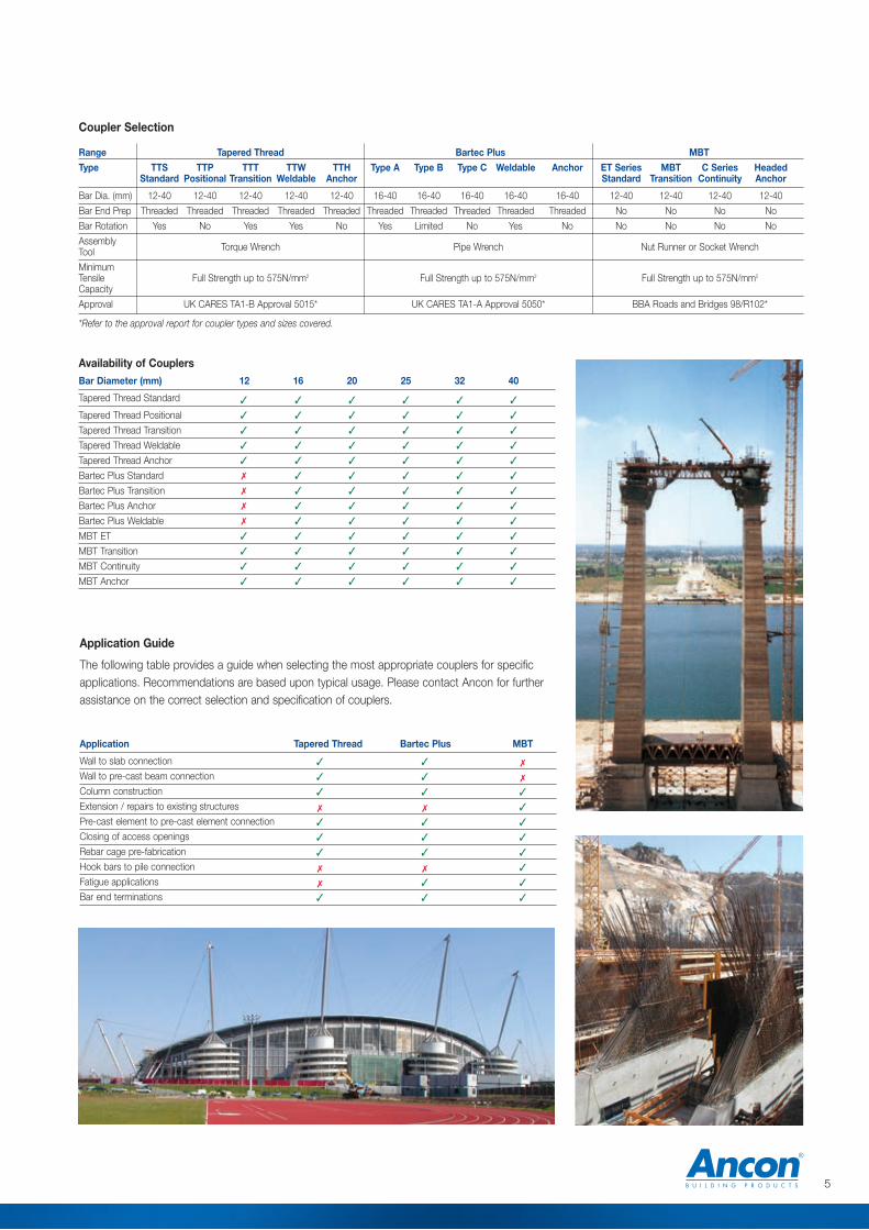
Availability of CouplersBar Diameter (mm) 12 16 20 25 32 40
Tapered Thread Standard
Tapered Thread Positional
Tapered Thread Transition
Tapered Thread Weldable
Tapered Thread Anchor
Bartec Plus Standard
Bartec Plus Transition
Bartec Plus Anchor
Bartec Plus Weldable
MBT ET
MBT Transition
MBT Continuity
MBT Anchor
� � � � � �
� � � � � �
� � � � � �
� � � � � �
� � � � � �
� � � � � �
� � � � � �
� � � � � �
� � � � � �
� � � � � �
� � � � � �
� � � � � �
� � � � � �
5
Application Guide
The following table provides a guide when selecting the most appropriate couplers for specificapplications. Recommendations are based upon typical usage. Please contact Ancon for furtherassistance on the correct selection and specification of couplers.
Application Tapered Thread Bartec Plus MBT
Wall to slab connection
Wall to pre-cast beam connection
Column construction
Extension / repairs to existing structures
Pre-cast element to pre-cast element connection
Closing of access openings
Rebar cage pre-fabrication
Hook bars to pile connection
Fatigue applications
Bar end terminations
� � �
� � �
� � �
� � �
� � �
� � �
� � �
� � �
� � �
� � �
Coupler Selection
Range Tapered Thread Bartec Plus MBTType TTS TTP TTT TTW TTH Type A Type B Type C Weldable Anchor ET Series MBT C Series Headed
Standard Positional Transition Weldable Anchor Standard Transition Continuity Anchor
Bar Dia. (mm) 12-40 12-40 12-40 12-40 12-40 16-40 16-40 16-40 16-40 16-40 12-40 12-40 12-40 12-40
Bar End Prep Threaded Threaded Threaded Threaded Threaded Threaded Threaded Threaded Threaded Threaded No No No No
Bar Rotation Yes No Yes Yes No Yes Limited No Yes No No No No No
Assembly Torque Wrench Pipe Wrench Nut Runner or Socket WrenchToolMinimumTensile Full Strength up to 575N/mm2 Full Strength up to 575N/mm2 Full Strength up to 575N/mm2
CapacityApproval UK CARES TA1-B Approval 5015* UK CARES TA1-A Approval 5050* BBA Roads and Bridges 98/R102*
*Refer to the approval report for coupler types and sizes covered.

Tapered ThreadThe Ancon range of Tapered Thread couplers is designed to suit themajority of applications which call for the joining of reinforcing bars.Available to suit bar sizes 12mm to 40mm, the couplers are installedquickly and easily on site without the need for specially trainedpersonnel or specialised, expensive machinery.
The compact design of each coupler ensures suitability for use in confined situations where spaceis restricted or where the loss of cover must be minimised. The couplers are normally suppliedfitted to the end of threaded bar, requiring only the engagement and tightening of the adjoining baron site. In order to ensure correct installation, Ancon Building Products specifies the use of atorque wrench. The range of Tapered Thread couplers is available through major rebar suppliers.Please contact Ancon for further details.
Standard CouplerThe Standard Tapered Thread coupler is suitable for connecting two bars of the same diameter,where one bar can be rotated. It comprises an internally threaded sleeve with two right handthreads which are tapered towards the middle of the coupler. The bar ends are square cut anda tapered thread is cut onto the bar. A nominal allowance of +25mm should be allowed perthreaded bar end for square cutting the bar end.
The couplers are generally torqued onto the reinforcing bar in the bar threading shop, the internalthreads protected by plastic end caps. The threaded ends of the continuation bar are protectedby plastic thread protectors.
Engagement of the bar within the coupler is simplified by the tapered thread design which aidsalignment. When the bar is fully engaged within the coupler, the continuation bar is tightened usinga torque wrench.
The Ancon Standard Tapered Thread coupler is designed for use in concrete structures to meetthe requirements of BS EN 1992-1-1: 2004 (Eurocode 2) and BS 8110 for mechanical splices.They are designed to achieve failure loads in excess of 115% of the characteristic strength ofgrade 500 rebar.
Reinforcing Bar Couplers
Bar Diameter (mm) 12 16 20 25 32 40
External Dia. (mm) d 22 25 30 36 48 60
Coupler Length (mm) l 58 70 74 90 112 138
Weight (kg) 0.13 0.17 0.25 0.43 0.99 1.90
Torque (Nm) 60 110 165 265 285 330
Part No. TTS12 TTS16 TTS20 TTS25 TTS32 TTS40
Standard Coupler Dimensions
Testing and ApprovalsThe Standard range of Tapered Thread couplers has been tested and approved by UK CARES toshow compliance with the requirements of BS EN 1992-1-1: 2004 (Eurocode 2) and BS 8110.
d
l
6 Tel: +44 (0) 114 275 5224 www.ancon.co.uk
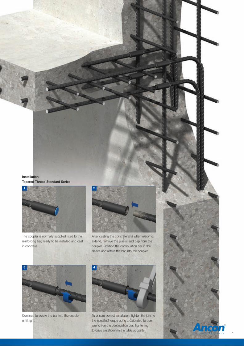
InstallationTapered Thread Standard Series
Continue to screw the bar into the coupler until tight.
After casting the concrete and when ready toextend, remove the plastic end cap from thecoupler. Position the continuation bar in thesleeve and rotate the bar into the coupler.
The coupler is normally supplied fixed to thereinforcing bar, ready to be installed and castin concrete.
To ensure correct installation, tighten the joint tothe specified torque using a calibrated torquewrench on the continuation bar. Tighteningtorques are shown in the table opposite.
1
4
2
3
7

lc
ls
lm
lo
le
Inla
li d2
Female component
Male componentLocknut
Positional CouplerThe Ancon Tapered Thread Positional coupler is designed to be usedin applications in which neither bar can be rotated. Having a degreeof adjustability, the Positional coupler can also be used as a closerbetween two fixed bars.The Positional coupler comprises three components, a male section, a female section and alocking nut. The male component has an internal tapered thread and an extended external parallelthread. The female component has a parallel thread and a tapered thread, both of which areinternal. A locknut is used to secure the connection when the correct degree of adjustability hasbeen achieved. All components, including the locknut must be tightened using a torque wrench.
Plastic thread protectors are used to prevent damage to the threaded bar ends and the internalthreads of the couplers are protected by plastic end caps. A nominal allowance of +25mm shouldbe allowed per threaded bar end for square cutting the bar end.
Testing & ApprovalsThe Positional range of Tapered Thread couplers has been tested and approved by UK CARES toshow compliance with the requirements of BS EN 1992-1-1: 2004 (Eurocode 2) and BS 8110.
Reinforcing Bar Couplers
Position the continuation bar as near aspossible to the coupler fitted to the cast-in bar.
Run the male component and locknut onto thecontinuation bar until fully engaged.
2
3
InstallationTapered Thread Positional Series
1
Bar Diameter 12 16 20 25 32 40External Dia. d1 25 30 36 48 55 70External Dia. d2 22 25 30 36 48 60Female Sleeve Length ls 84 95 112 132 153 190Locknut Length ln 13 13 13 13 15 15Closed Length lc 138 155 180 207 243 296Max. Open Length lo 178 196 231 266 305 374Bar Insertion Prior to Engagement li 9 15 8 16 28 40Bar Insertion Full Engagement le 26 32 33 42 53 66Adjustable Length la 23 24 26 34 37 52Max Distance between Bar Ends lm 126 132 165 182 199 242Weight (kg) 0.44 0.67 1.12 2.21 3.51 6.91Coupler Torque (Nm) 60 110 165 265 285 330Locknut Torque (Nm) 20 30 50 70 90 110Part No. TTP12 TTP16 TTP20 TTP25 TTP32 TTP40
Positional Coupler Dimensions
The female section of the positional coupler isnormally cast flush in the concrete. The installermust take care to protect the internal threadsand prevent the ingress of concrete. Once castand ready to extend, the male end completewith locknut can be screwed into place.
8 Tel: +44 (0) 114 275 5224 www.ancon.co.uk
d1

Using a torque wrench tighten the malecomponent on the continuation bar to thespecified torque, whilst holding thecontinuation bar with a second wrench.
Run the locknut along the threaded barrel ofthe male component to abut the femalesection. Using the torque wrench, tighten the locknut to the specified torque. Tighteningtorques are shown in the table opposite.
At this point the groove in the parallel threadedsection of the male component must becompletely covered by the locknut. If any partof the groove is visible beyond the locknut, thedegree of adjustability has been exceeded andthe installation is incorrect.
Incorrect Installation
Groove is completely hidden within locknut
4
5
Correct Installation
Groove is protruding from locknut
9
d
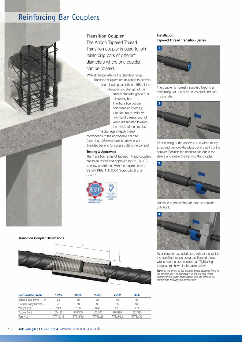
After casting of the concrete and when readyto extend, remove the plastic end cap from thecoupler. Position the continuation bar in thesleeve and rotate the bar into the coupler.
Continue to screw the bar into the coupler until tight.
To ensure correct installation, tighten the joint tothe specified torque using a calibrated torquewrench on the continuation bar. Tighteningtorques are shown in the table below.Note: In the event of the coupler being supplied fixed tothe smaller bar it is necessary to ensure that whentightening the larger continuation bar, the force is nottransmitted through the smaller bar.
2
3
4
1
The coupler is normally supplied fixed to areinforcing bar, ready to be installed and castin concrete.
Transition CouplerThe Ancon Tapered ThreadTransition coupler is used to joinreinforcing bars of differentdiameters where one couplercan be rotated.With all the benefits of the Standard range,
Transition couplers are designed to achievefailure loads greater than 115% of the
characteristic strength of thesmaller diameter grade 500reinforcing bar.The Transition couplercomprises an internallythreaded sleeve with tworight hand threads both ofwhich are tapered towardsthe middle of the coupler.
The diameter of each threadcorresponds to the appropriate bar size. A nominal +25mm should be allowed perthreaded bar end for square cutting the bar end.
InstallationTapered Thread Transition Series
Testing & ApprovalsThe Transition range of Tapered Thread couplershas been tested and approved by UK CARESto show compliance with the requirements ofBS EN 1992-1-1: 2004 (Eurocode 2) and BS 8110.
d
l
Transition Coupler Dimensions
Bar Diameter (mm) 12/16 16/20 20/25 25/32 32/40
External Dia. (mm) d 25 30 36 48 55
Coupler Length (mm) l 72 78 90 112 138
Weight (kg) 0.21 0.30 0.48 1.11 1.62
Torque (Nm) 60/110 110/165 165/265 265/285 285/330
Part No. TTT12/16 TTT16/20 TTT20/25 TTT25/32 TTT32/40
10 Tel: +44 (0) 114 275 5224 www.ancon.co.uk
Reinforcing Bar Couplers
d
11
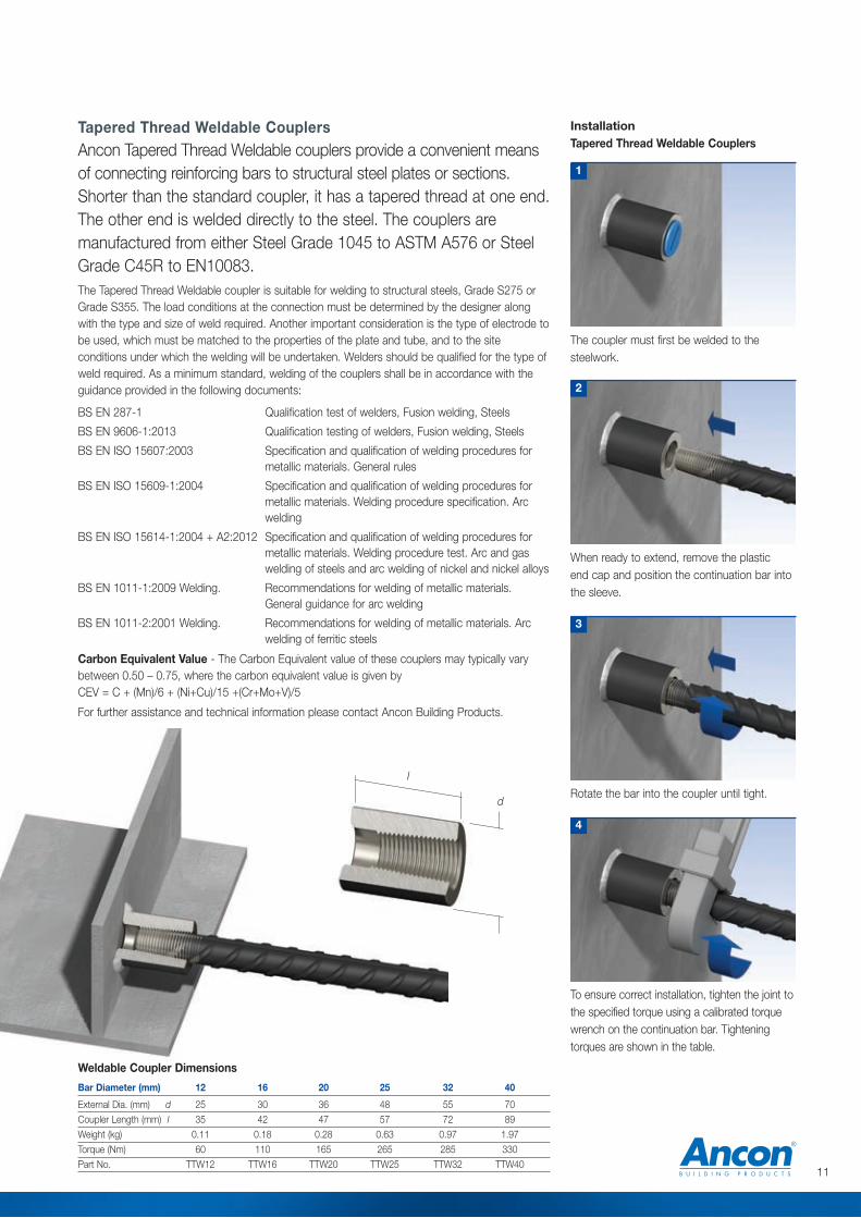
The coupler must first be welded to thesteelwork.
1
Rotate the bar into the coupler until tight.
3
4
InstallationTapered Thread Weldable Couplers
When ready to extend, remove the plastic end cap and position the continuation bar intothe sleeve.
2
To ensure correct installation, tighten the joint tothe specified torque using a calibrated torquewrench on the continuation bar. Tighteningtorques are shown in the table.
Bar Diameter (mm) 12 16 20 25 32 40
External Dia. (mm) d 25 30 36 48 55 70
Coupler Length (mm) l 35 42 47 57 72 89
Weight (kg) 0.11 0.18 0.28 0.63 0.97 1.97
Torque (Nm) 60 110 165 265 285 330
Part No. TTW12 TTW16 TTW20 TTW25 TTW32 TTW40
Weldable Coupler Dimensions
Tapered Thread Weldable CouplersAncon Tapered Thread Weldable couplers provide a convenient meansof connecting reinforcing bars to structural steel plates or sections.Shorter than the standard coupler, it has a tapered thread at one end.The other end is welded directly to the steel. The couplers aremanufactured from either Steel Grade 1045 to ASTM A576 or SteelGrade C45R to EN10083.The Tapered Thread Weldable coupler is suitable for welding to structural steels, Grade S275 orGrade S355. The load conditions at the connection must be determined by the designer alongwith the type and size of weld required. Another important consideration is the type of electrode tobe used, which must be matched to the properties of the plate and tube, and to the siteconditions under which the welding will be undertaken. Welders should be qualified for the type ofweld required. As a minimum standard, welding of the couplers shall be in accordance with theguidance provided in the following documents:
BS EN 287-1 Qualification test of welders, Fusion welding, Steels
BS EN 9606-1:2013 Qualification testing of welders, Fusion welding, Steels
BS EN ISO 15607:2003 Specification and qualification of welding procedures formetallic materials. General rules
BS EN ISO 15609-1:2004 Specification and qualification of welding procedures formetallic materials. Welding procedure specification. Arcwelding
BS EN ISO 15614-1:2004 + A2:2012 Specification and qualification of welding procedures formetallic materials. Welding procedure test. Arc and gaswelding of steels and arc welding of nickel and nickel alloys
BS EN 1011-1:2009 Welding. Recommendations for welding of metallic materials.General guidance for arc welding
BS EN 1011-2:2001 Welding. Recommendations for welding of metallic materials. Arcwelding of ferritic steels
Carbon Equivalent Value - The Carbon Equivalent value of these couplers may typically varybetween 0.50 – 0.75, where the carbon equivalent value is given by CEV = C + (Mn)/6 + (Ni+Cu)/15 +(Cr+Mo+V)/5
For further assistance and technical information please contact Ancon Building Products.
l
Reinforcing Bar Couplers
Torque Values (Nm)
Torque Wrenches for Couplers and Locknuts
Part No. E879008 E879009 E879010
Torque (Nm) 60 - 285 85 - 350 20 - 90
Torque Wrenches
Bar Diameter (mm) 12 16 20 25 32 40
Standard Coupler 60 110 165 265 285 330
Positional Coupler 60 110 165 265 285 330
Positional Locknut 20 30 50 70 90 110
Bar Diameter (mm) 12/16 16/20 20/25 25/32 32/40
Transition Coupler 60/110 110/165 165/265 265/285 285/330
Bar Diameter (mm) 12 16 20 25 32 40
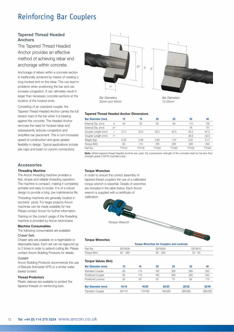
External Dia. (mm) d 40 50 65 80 110 135
External Dia. (mm) d1 - - - - 78 78
Coupler Length (mm) l 27.0 33.0 35.0 43.5 53.5 67.5
Coupler Length (mm) l1 - - - - 28.5 42.5
Weight (kg) 0.25 0.46 0.83 1.57 2.81 5.17
Torque (Nm) 60 110 165 265 285 330
Part No. TTH12 TTH16 TTH20 TTH25 TTH32 TTH40
Note: Where tapered thread headed anchors are used, the compressive strength of the concrete shall not be less thanstrength grade C32/40 (cylinder/cube).
Tapered Thread HeadedAnchorsThe Tapered Thread HeadedAnchor provides an effectivemethod of achieving rebar endanchorage within concrete.Anchorage of rebars within a concrete sectionis traditionally achieved by means of creating along hooked end on the rebar. This can lead toproblems when positioning the bar and canincrease congestion. It can ultimately result inlarger than necessary concrete sections at thelocation of the hooked ends.
Consisting of an oversized coupler, theTapered Thread Headed Anchor carries the fulltension load of the bar when it is bearingagainst the concrete. The Headed Anchorremoves the need for hooked rebar andsubsequently reduces congestion andsimplifies bar placement. This in turn increasesspeed of construction and gives greaterflexibility in design. Typical applications includepile caps and beam to column connections.
AccessoriesThreading MachineThe Ancon threading machine provides afast, simple and reliable threading operation.The machine is compact, making it completelyportable and easy to locate. It is of a robustdesign to provide a long, low maintenance life.
Threading machines are generally located instockists’ yards. For larger projects Anconmachines can be made available for hire.Please contact Ancon for further information.
Training on the correct usage of the threadingmachine is provided by Ancon technicians.
Machine ConsumablesThe following consumables are available:Chaser SetsChaser sets are available on a regrindable ordisposable basis. Each set can be reground upto 3 times in order to extend cutting life. Pleasecontact Ancon Building Products for details.
CoolantAncon Building Products recommends the useof Batoyle Solmaster EPS or a similar waterbased coolant.
Thread ProtectorsPlastic sleeves are available to protect thetapered threads on reinforcing bars.
d dd1
l
l1
Bar Diameters32mm and 40mm
Bar Diameters12-25mm
l
Tapered Thread Headed Anchor Dimensions
Torque Wrench
12 Tel: +44 (0) 114 275 5224 www.ancon.co.uk
Torque Wrenches In order to ensure the correct assembly oftapered thread couplers the use of a calibratedtorque wrench is essential. Details of wrenchesare included in the table below. Each Anconwrench is supplied with a certificate ofcalibration.
BT-S CouplersBar Diameter (mm) 16 20 25 32 40
External Diameter (mm) 30 35 42 52 65
Coupler Length (mm) 40 48 60 72 90
Thread Form M20 x 2.5 M24 x 3.0 M30 x 3.5 M36 x 4.0 M45 x 4.5
Weight (kg) 0.14 0.22 0.37 0.72 1.37
Coupler Reference BTS16 BTS20 BTS25 BTS32 BTS40
BT-S LocknutsBar Diameter (mm) 16 20 25 32 40
External Diameter (mm) 30 35 42 52 65
Locknut Length (mm) 13 16 20 24 30
Thread Form M20 x 2.5 M24 x 3.0 M30 x 3.5 M36 x 4.0 M45 x 4.5
Weight (kg) 0.05 0.07 0.12 0.24 0.46
Coupler Reference BTS16LN BTS20LN BTS25LN BTS32LN BTS40LN
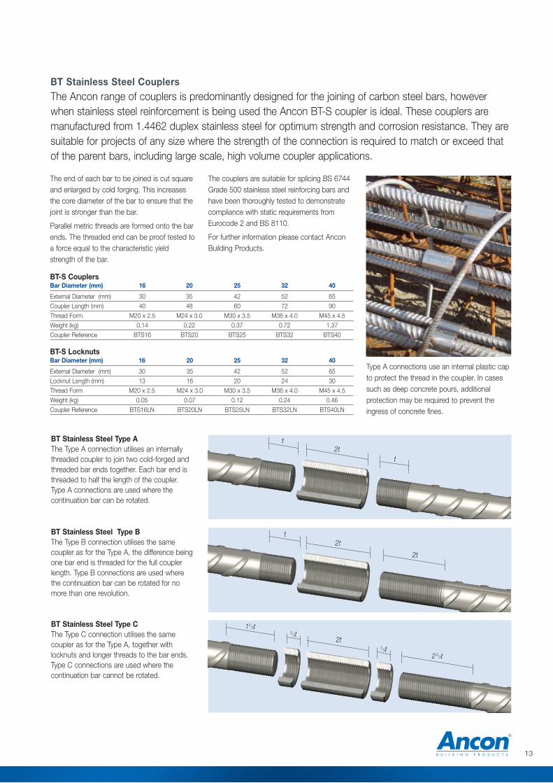
BT Stainless Steel CouplersThe Ancon range of couplers is predominantly designed for the joining of carbon steel bars, howeverwhen stainless steel reinforcement is being used the Ancon BT-S coupler is ideal. These couplers aremanufactured from 1.4462 duplex stainless steel for optimum strength and corrosion resistance. They aresuitable for projects of any size where the strength of the connection is required to match or exceed thatof the parent bars, including large scale, high volume coupler applications.
13
The end of each bar to be joined is cut squareand enlarged by cold forging. This increasesthe core diameter of the bar to ensure that thejoint is stronger than the bar.
Parallel metric threads are formed onto the barends. The threaded end can be proof tested toa force equal to the characteristic yieldstrength of the bar.
The couplers are suitable for splicing BS 6744Grade 500 stainless steel reinforcing bars andhave been thoroughly tested to demonstratecompliance with static requirements fromEurocode 2 and BS 8110.
For further information please contact AnconBuilding Products.
Type A connections use an internal plastic capto protect the thread in the coupler. In casessuch as deep concrete pours, additionalprotection may be required to prevent theingress of concrete fines.
BT Stainless Steel Type AThe Type A connection utilises an internallythreaded coupler to join two cold-forged andthreaded bar ends together. Each bar end isthreaded to half the length of the coupler.Type A connections are used where thecontinuation bar can be rotated.
BT Stainless Steel Type BThe Type B connection utilises the samecoupler as for the Type A, the difference beingone bar end is threaded for the full couplerlength. Type B connections are used wherethe continuation bar can be rotated for nomore than one revolution.
BT Stainless Steel Type CThe Type C connection utilises the samecoupler as for the Type A, together withlocknuts and longer threads to the bar ends.Type C connections are used where thecontinuation bar cannot be rotated.
2tt
t
2tt
12/3t
2t2/3t
2 2/3t
2t
2/3t

14 Tel: +44 (0) 114 275 5224 www.ancon.co.uk
Reinforcing Bar Couplers
dl
Bartec Plus Couplers
Bartec Plus Type AThe Type A connection utilises an internallythreaded coupler to join two cold-forged andthread-rolled bar ends together. Each bar endis threaded to half the length of the coupler.Type A connections are used where thecontinuation bar can be rotated.
Bartec Plus Type BThe Type B connection utilises the samecoupler as for the Type A, the difference beingone bar end is threaded for the full couplerlength. Type B connections are used wherethe continuation bar can be rotated for nomore than one revolution.
Bartec Plus Type CThe Type C connection utilises the samecoupler as for the Type A, together withlocknuts and longer threads to the bar ends.Type C connections are used where thecontinuation bar cannot be rotated.
Each end of the rebar to be joined is cutsquare and enlarged using a cold forgeprocess. A thread is then formed on theenlarged bar end using a thread rollingmachine. The thread is such that the cross-sectional area of the bar ends are not reducedensuring the strength of the connectionmatches or exceeds that of the parent bars.
It is the application of the rolled thread thatdifferentiates Bartec Plus from other threadedrebar systems. Each thread-rolled bar end isproof-loaded to a force equal to thecharacteristic yield strength of the rebar. It isthe combination of these processes thatprovide the connection with enhanced fatigueresistance.
Ancon Bartec Plus Type A standard couplersin the size range 16mm to 32mm and Type Cpositional couplers in the size range 16mm to40mm are covered by UK CARES TechnicalApproval TA1-A 5050, having been evaluatedfor use as follows:
• TA1-B: Eurocode 2 and BS 8110 for staticapplications in tension only with BS4449Grade B500C reinforcement
• TA1-A: Class D fatigue requirements withBS4449 Grade B500C reinforcement
Type A connections use an internal plastic capto protect the thread in the coupler. In casessuch as deep concrete pours, additionalprotection may be required to prevent theingress of concrete fines. For 40mm Type Cconnections, the diameter of the locknuts willbe marginally smaller than that of the BTP40coupler.
2tt
t
2tt
12/3t
2t2/3t
2 2/3t
2t
2/3t
Bartec Plus
Bar Diameter (mm) 16 20 25 32 40External Diameter (mm) d 26.4 32.1 40.1 49.5 67.5Coupler Length (mm) l 40 48 60 72 90Thread Form M20x2.5 M24x3.0 M30x3.5 M36x4.0 M45x4.5Weight (kg) 0.09 0.16 0.31 0.57 1.53Coupler Reference BTP16 BTP20 BTP25 BTP32 BTP40Other sizes are available on request. Contact Ancon for more details.
Bartec Plus Type A
Bartec Plus LocknutsBar Diameter (mm) 16 20 25 32 40External Diameter (mm) 26.4 32.1 40.1 49.5 67.5Locknut Length (mm) 13 16 20 24 30Thread Form M20x2.5 M24x3.0 M30x3.5 M36x4.0 M45x4.5Weight (kg) 0.04 0.05 0.10 0.19 0.50Locknut Reference BTP16LN BTP20LN BTP25LN BTP32LN BTP40LNOther sizes are available on request. Contact Ancon for more details.
Bartec Plus couplers offer a full strength connection together with enhanced fatigue resistance, yet are thesmallest in the Ancon range. They are suitable for projects of any size, including those requiring a highvolume of couplers, such as road and rail bridges.
15
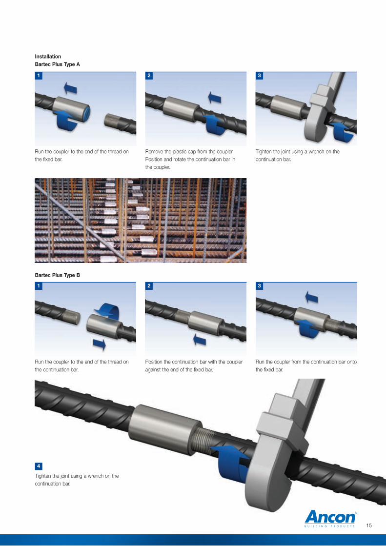
Remove the plastic cap from the coupler.Position and rotate the continuation bar in the coupler.
2 3
InstallationBartec Plus Type A
Tighten the joint using a wrench on thecontinuation bar.
Position the continuation bar with the coupleragainst the end of the fixed bar.
Run the coupler from the continuation bar ontothe fixed bar.
2 3
Bartec Plus Type B
Run the coupler to the end of the thread onthe continuation bar.
1
Tighten the joint using a wrench on thecontinuation bar.
Run the coupler to the end of the thread onthe fixed bar.
1
4

16 Tel: +44 (0) 114 275 5224 www.ancon.co.uk
Reinforcing Bar Couplers
Run the second locknut followed by thecoupler to the end of the thread on thecontinuation bar.
Position the continuation bar with the coupleragainst the end of the fixed bar.
2 3
Run the locknut onto the fixed bar.
1
Run the locknut along the continuation bar toabut the coupler and lock tight with a wrench.
5
Run the coupler from the continuation bar ontothe fixed bar and using a wrench lock tightagainst the locknut.
4
InstallationBartec Plus Type C

17
d
l
Bartec Plus Transition Couplers
For transition connections, only the smallerdiameter bar end is enlarged and thread-rolled.The larger diameter bar is simply skimmed andthread-rolled with the same thread form asapplied to the smaller diameter bar, excludingthe 32mm to 40mm connection. Refer to thetable for thread and coupler details.
The threads are such that the cross-sectionalarea of the bar ends are not reduced beyondthat of the smaller diameter bar, thus ensuringthe strength of the connection matches orexceeds that of the smaller bar.
As with Bartec Plus standard coupler systems,each enlarged and thread-rolled bar end isproof-loaded to a force equal to thecharacteristic yield strength of the rebar. It isthe combination of these processes thatprovide the connection with an enhancedfatigue resistance.
Type A connections use an internal plastic capto protect the thread in the coupler. In casessuch as deep concrete pours, additionalprotection maybe required to prevent theingress of concrete fines. For 40mm Type Cconnections, the diameter of the locknuts willbe marginally smaller than that of the BTP40coupler.
Bartec Plus Transition Couplers
Bar Diameter (mm) 16/20 20/25 25/32 32/40External Diameter (mm) d 26.4 32.1 40.1 53Coupler Length (mm) l 40 48 60 72Thread Form M20x2.5 M24x3.0 M30x3.5 M36x4.0/M40x4.0Weight (kg) 0.09 0.16 0.31 0.67Coupler Reference BTP16 BTP20 BTP25 BTP32/40Other sizes are available on request. Contact Ancon for more details.
Bartec Plus Transition Type A
Bartec Plus Transition LocknutsBar Diameter (mm) 16/20 20/25 25/32 32 40External Diameter (mm) 26.4 32.1 40.1 49.5 53Locknut Length (mm) 13 16 20 24 30Thread Form M20x2.5 M24x3.0 M30x3.5 M36x4.0 M40x.4.0Weight (kg) 0.04 0.05 0.10 0.19 0.26Locknut Reference BTP16LN BTP20LN BTP25LN BTP32LN BTP40LNOther sizes are available on request. Contact Ancon for more details.
Bartec Plus Transition Type BThe Type B connection utilises the samecoupler as for the Type A, the difference beingone bar end is threaded for the full couplerlength. It is usual to rotate the coupler fromthe smaller diameter rebar onto the larger.Type B connections are used where thecontinuation bar can be rotated for no morethan one revolution.
Bartec Plus Transition Type CThe Type C connection utilises the samecoupler as for the Type A, together with twolocknuts and longer threads on the bar ends.It is usual to rotate the coupler from thesmaller diameter rebar onto the larger. Type Cconnections are used where the continuationbar cannot be rotated.
2tt
t
2tt
12/3t
2t2/3t
2 2/3t
2t
2/3t
Bartec Plus Transition Type AThe Type A connection utilises an internallythreaded coupler to join two cold-forged andthread-rolled bar ends together. Each bar endis threaded to half the length of the coupler.Type A connections are used where thecontinuation bar can be rotated.
Bartec Plus couplers can be used to connect reinforcing bars of differing diameters, developing the fulltensile strength of the smaller diameter bar together with the enhanced fatigue resistance.
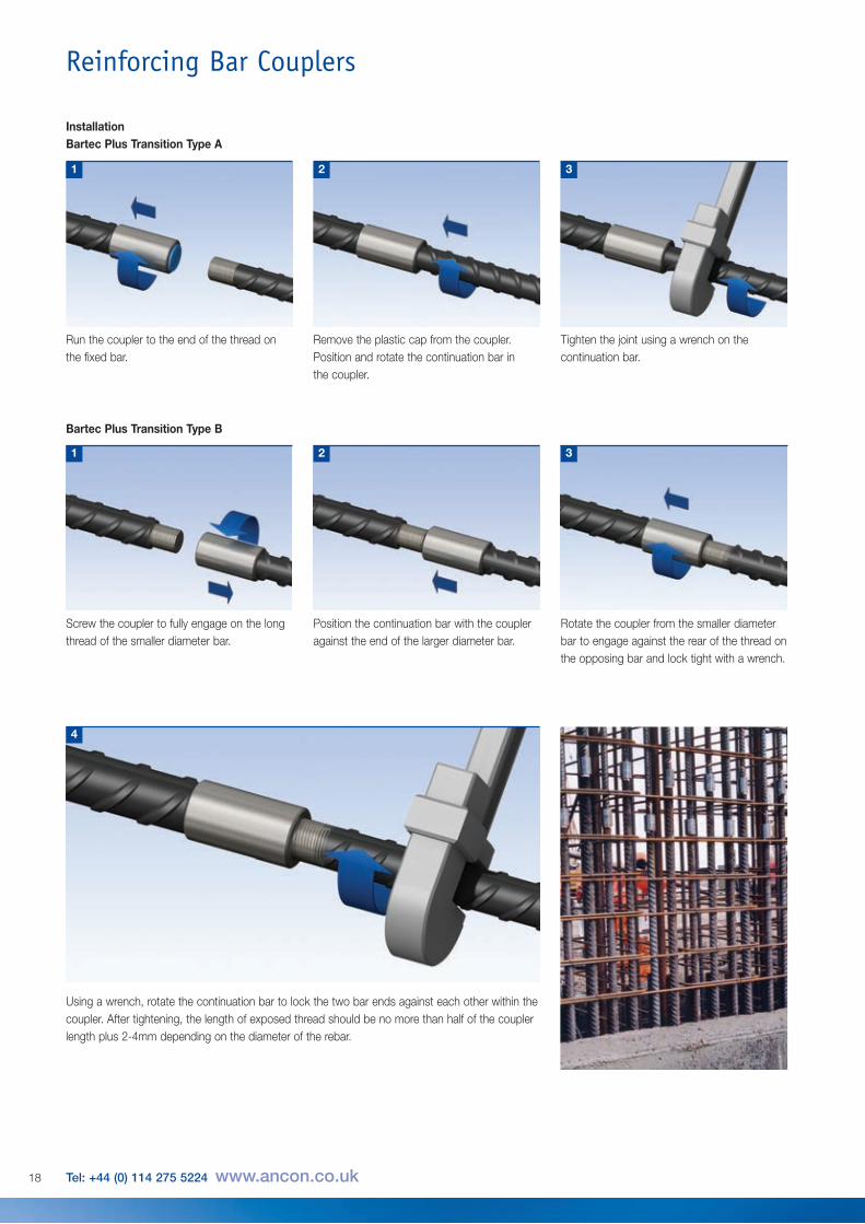
InstallationBartec Plus Transition Type A
Position the continuation bar with the coupleragainst the end of the larger diameter bar.
Rotate the coupler from the smaller diameterbar to engage against the rear of the thread onthe opposing bar and lock tight with a wrench.
2 3
Bartec Plus Transition Type B
Screw the coupler to fully engage on the longthread of the smaller diameter bar.
1
Using a wrench, rotate the continuation bar to lock the two bar ends against each other within thecoupler. After tightening, the length of exposed thread should be no more than half of the couplerlength plus 2-4mm depending on the diameter of the rebar.
Run the coupler to the end of the thread onthe fixed bar.
1
4
Remove the plastic cap from the coupler.Position and rotate the continuation bar in the coupler.
Tighten the joint using a wrench on thecontinuation bar.
2 3
Reinforcing Bar Couplers
18 Tel: +44 (0) 114 275 5224 www.ancon.co.uk
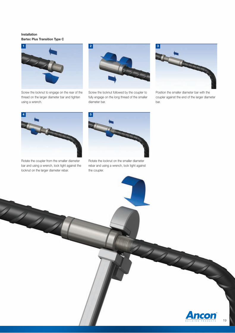
Screw the locknut followed by the coupler tofully engage on the long thread of the smallerdiameter bar.
Position the smaller diameter bar with thecoupler against the end of the larger diameterbar.
2 3
Screw the locknut to engage on the rear of thethread on the larger diameter bar and tightenusing a wrench.
1
Rotate the locknut on the smaller diameterrebar and using a wrench, lock tight againstthe coupler.
5
Rotate the coupler from the smaller diameterbar and using a wrench, lock tight against thelocknut on the larger diameter rebar.
4
InstallationBartec Plus Transition Type C
19

Anchorage of reinforcement within a concretesection is traditionally achieved by means ofcreating a long hooked end to the bar. Thesehooks can lead to problems when positioningthe bar and can increase congestion. It canultimately result in larger than necessaryconcrete sections at the location of hookedends.
The Bartec Plus Headed Anchor is essentiallyan oversized coupler capable of carrying the fulltension load of the bar when it bears againstthe concrete in which it is cast. The HeadedAnchor removes the need for the hooked rebarend and subsequently reduces congestion,simplifying bar placement. This in turnincreases the speed of construction and givesgreater flexibility in design. Typical applicationsinclude pile caps and beam-to-columnconnections.
To attach the Headed Anchor to the rebar, it isfirst necessary to enlarge the bar end and thenform the thread on the enlarged bar end usinga thread rolling machine. As with theconventional coupler connection, the thread issuch that the cross-sectional area of the barend is not reduced, thus ensuring the strengthof the connection matches or exceeds that ofthe parent bar.
Bartec Plus Headed Anchors
d
l
Bartec Plus Headed AnchorsBar Diameter (mm) 16 20 25 32 40External Diameter (mm) d 50 65 80 110 135Anchor Thickness (mm) l 20 24 30 36 45Thread Form M20x2.5 M24x3.0 M30x3.5 M36x4.0 M45x4.5Weight (kg) 0.27 0.56 1.03 2.43 4.55Anchor Reference BTP16HA BTP20HA BTP25HA BTP32HA BTP40HAOther sizes are available on request. Contact Ancon for more details.
Concrete StrengthWhen the above sizes of Bartec Plus Headed Anchors are used, the compressive strength of theconcrete shall not be less than strength grade C32/40 (cylinder/cube). Where required, HeadedAnchors can be supplied to a larger diameter than shown above.
Bartec Plus Type A and Type C Couplers, Forth Replacement Crossing, UK (Photo courtesy of Transport Scotland)
20 Tel: +44 (0) 114 275 5224 www.ancon.co.uk
Reinforcing Bar Couplers
The Bartec Plus Headed Anchor provides an effective and proven method of achieving rebar endanchorage within concrete.
21
The coupler is suitable for welding to structural steels EN BS 10025, Grade S275 (43A) orGrade S355 (Grade 50B), however the load conditions at the connection must be determinedby the designer responsible for this structural element, along with the type and size of weldrequired. Other important considerations are the type of electrode to be used, which must bematched to the properties of the plate and tube, and to the site conditions under which thewelding will be undertaken. Welders should be qualified for the type of weld required.
As a minimum standard, welding of the couplers shall be in accordance with the guidanceprovided in the following documents:
BS EN 287-1 Qualification test of welders, Fusion welding, Steels
BS EN 9606-1:2013 Qualification testing of welders, Fusion welding,Steels
BS EN ISO 15607:2003 Specification and qualification of welding proceduresfor metallic materials. General rules
BS EN ISO 15609-1:2004 Specification and qualification of welding proceduresfor metallic materials. Welding procedurespecification. Arc welding
BS EN ISO 15614-1:2004 + A2:2012 Specification and qualification of welding proceduresfor metallic materials. Welding procedure test. Arcand gas welding of steels and arc welding of nickeland nickel alloys
BS EN 1011-1: 2009 Welding. Recommendations for welding of metallic materials.General guidance for arc welding
BS EN 1011-2:2001 Welding. Recommendations for welding of metallic materials.Arc welding of ferritic steels
Bartec Plus Weldable Couplers are manufactured from either Steel Grade 1045 to ASTMA576 or Steel Grade C45R to EN10083.
Carbon Equivalent Value - The Carbon Equivalent value of these couplers may typicallyvary between 0.50 – 0.75, where the carbon equivalent value is given byCEV = C + (Mn)/6 + (Ni+Cu)/15 +(Cr+Mo+V)/5
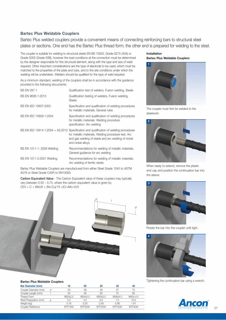
Bartec Plus Weldable Couplers
The coupler must first be welded to thesteelwork.
1
Rotate the bar into the coupler until tight.
3
4
InstallationBartec Plus Weldable Couplers
When ready to extend, remove the plastic end cap and position the continuation bar intothe sleeve.
2
Tightening the continuation bar using a wrench.Bartec Plus Weldable CouplersBar Diameter (mm) 16 20 25 32 40Coupler Diameter (mm) d 33 38 48 57 72Coupler Length (mm) l 40 48 60 72 90Thread Form M20x2.5 M24x3.0 M30x3.5 M36x4.0 M45x.4.5Weld Preparation (mm) p 5.5 4.0 6.0 7.5 10.5Weight (kg) 0.18 0.30 0.58 0.96 1.91Coupler Reference BTP16W BTP20W BTP25W BTP32W BTP40W
Bartec Plus welded couplers provide a convenient means of connecting reinforcing bars to structural steelplates or sections. One end has the Bartec Plus thread form; the other end is prepared for welding to the steel.
d
lp

MBT Couplers are easy to install and achievefailure loads higher than 115% of thecharacteristic yield strength of grade 500reinforcing bar. Neither bar end preparation toform threads, nor bar rotation are required.MBT couplers can also be used to joinimperial, plain round or deformed reinforcingbars.
The bar ends are supported within the couplerby two serrated saddles, and as the lockshearbolts are tightened, the conical ends embedthemselves into the bar. As this happens theserrated saddles bite into both the bar and theshell of the coupler. The lockshear bolts ofcouplers up to and including the ET20 can betightened using a ratchet wrench. For largercouplers a nut runner is recommended.
In all cases heavy duty sockets should be used.When the pre-determined tightening torque forthe bolts is reached, the heads shear off leavingthe top of the installed bolt slightly proud of thecoupler. This provides an instant visual check ofcorrect installation.Note: Impact tools must not be used to tightenlockshear bolts.
MBT ET SeriesThe MBT ET series of couplers is used toconnect reinforcing bars of the same size.
Bar Diameter (mm) 12 16 20 25 32 40
External Diameter (mm) d 33.4 42.2 48.3 54.0 71.0 81.0Total Length (mm) l 140 160 204 258 312 484Socket Size A/F (ins) 1/2
1/21/2
5/85/8
3/4
No. of Bolts 6 6 8 8 10 14Approx Weight (kg) 0.72 1.25 1.96 3.00 6.50 11.30Torque (Nm) 55 108 108 275 360 525Part No. ET12 ET16 ET20 ET25 ET32 ET40
Note: Other sizes available on request. For details contact Ancon Building Products.
l
d
MBT ET Series Dimensions
MBTThe MBT range of couplers provides a cost-effective method of joining reinforcing bars, particularly whenthe fixed bar is already in place and there is insufficient space for a hydraulic swaging press.
Testing & ApprovalsFull destructive tests arecarried out on selectedcouplers from ourstocks. MBT couplers aredesigned and manufactured in accordancewith BS EN ISO 9001. The most commonsizes of ET series couplers are approved bythe BBA and are covered by the Roads andBridges Agrément Certificate No. 98/R102,including the bar sizes featured in the tablebelow.
Section showing the embedment of thelockshear bolts and saddles into thebar and the shell of the coupler
Lockshear bolt
Reduced diametershear plane
Serrated saddle
22 Tel: +44 (0) 114 275 5224 www.ancon.co.uk
Reinforcing Bar Couplers
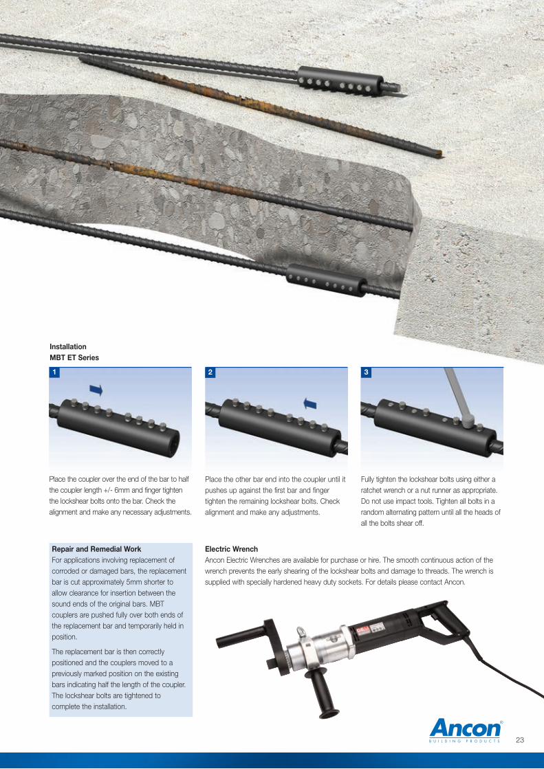
Place the other bar end into the coupler until itpushes up against the first bar and fingertighten the remaining lockshear bolts. Checkalignment and make any adjustments.
Fully tighten the lockshear bolts using either aratchet wrench or a nut runner as appropriate.Do not use impact tools. Tighten all bolts in arandom alternating pattern until all the heads ofall the bolts shear off.
2 3
InstallationMBT ET Series
Place the coupler over the end of the bar to halfthe coupler length +/- 6mm and finger tightenthe lockshear bolts onto the bar. Check thealignment and make any necessary adjustments.
1
23
Repair and Remedial WorkFor applications involving replacement ofcorroded or damaged bars, the replacementbar is cut approximately 5mm shorter toallow clearance for insertion between thesound ends of the original bars. MBTcouplers are pushed fully over both ends ofthe replacement bar and temporarily held inposition.
The replacement bar is then correctlypositioned and the couplers moved to apreviously marked position on the existingbars indicating half the length of the coupler.The lockshear bolts are tightened tocomplete the installation.
Electric WrenchAncon Electric Wrenches are available for purchase or hire. The smooth continuous action of thewrench prevents the early shearing of the lockshear bolts and damage to threads. The wrench issupplied with specially hardened heavy duty sockets. For details please contact Ancon.
l
a
d
b
d2
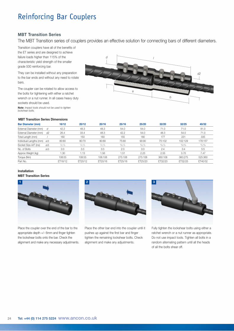
MBT Transition Series DimensionsBar Diameter (mm) 16/12 20/12 20/16 25/16 25/20 32/20 32/25 40/32
External Diameter (mm) d 42.2 48.3 48.3 54.0 54.0 71.0 71.0 81.0External Diameter (mm) d2 26.4 33.4 48.3 42.2 54.0 48.3 54.0 71.0Total Length (mm) l 160 150 160 155 180 177 231 335Individual Lengths (mm) a:b 80:80 80:70 80:80 75:80 90:90 75:102 102:129 178:157Socket Size A/F (ins) a:b 1/2:1/2
1/2:1/21/2:1/2
5/8:1/25/8:1/2
5/8:1/25/8:5/8
3/4:5/8
No. of Bolts a:b 3:3 3:3 3:3 2:3 3:3 2:4 3:4 5:5Approx Weight (kg) 1.30 1.13 1.56 1.51 2.23 2.55 3.70 7.47
Torque (Nm) 108:55 108:55 108:108 275:108 275:108 360:108 360:275 525:360
Part No. ET16/12 ET20/12 ET20/16 ET25/16 ET25/20 ET32/20 ET32/25 ET40/32
Place the other bar end into the coupler until itpushes up against the first bar and fingertighten the remaining lockshear bolts. Checkalignment and make any adjustments.
2
InstallationMBT Transition Series
Place the coupler over the end of the bar to theappropriate depth +/- 6mm and finger tightenthe lockshear bolts onto the bar. Check thealignment and make any necessary adjustments.
1
Fully tighten the lockshear bolts using either aratchet wrench or a nut runner as appropriate.Do not use impact tools. Tighten all bolts in arandom alternating pattern until all the headsof all the bolts shear off.
3
Transition couplers have all of the benefits ofthe ET series and are designed to achievefailure loads higher than 115% of thecharacteristic yield strength of the smallergrade 500 reinforcing bar.
They can be installed without any preparationto the bar ends and without any need to rotatebars.
The coupler can be rotated to allow access tothe bolts for tightening with either a ratchetwrench or a nut runner. In all cases heavy dutysockets should be used. Note: Impact tools should not be used to tightenlockshear bolts.
MBT Transition SeriesThe MBT Transition series of couplers provides an effective solution for connecting bars of different diameters.
Reinforcing Bar Couplers
24 Tel: +44 (0) 114 275 5224 www.ancon.co.uk
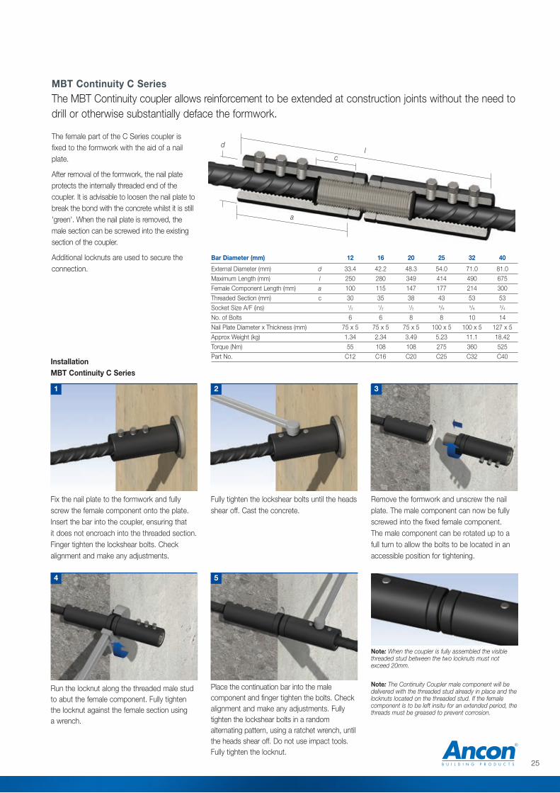
Fix the nail plate to the formwork and fullyscrew the female component onto the plate.Insert the bar into the coupler, ensuring that it does not encroach into the threaded section.Finger tighten the lockshear bolts. Checkalignment and make any adjustments.
Run the locknut along the threaded male studto abut the female component. Fully tighten the locknut against the female section using a wrench.
Note: When the coupler is fully assembled the visiblethreaded stud between the two locknuts must notexceed 20mm.
4
Fully tighten the lockshear bolts until the headsshear off. Cast the concrete.
2
Place the continuation bar into the malecomponent and finger tighten the bolts. Checkalignment and make any adjustments. Fullytighten the lockshear bolts in a randomalternating pattern, using a ratchet wrench, untilthe heads shear off. Do not use impact tools.Fully tighten the locknut.
5
InstallationMBT Continuity C Series
1
Remove the formwork and unscrew the nailplate. The male component can now be fullyscrewed into the fixed female component.The male component can be rotated up to afull turn to allow the bolts to be located in anaccessible position for tightening.
3
Note: The Continuity Coupler male component will bedelivered with the threaded stud already in place and thelocknuts located on the threaded stud. If the femalecomponent is to be left insitu for an extended period, thethreads must be greased to prevent corrosion.
l
a
d
c
Bar Diameter (mm) 12 16 20 25 32 40
External Diameter (mm) d 33.4 42.2 48.3 54.0 71.0 81.0Maximum Length (mm) l 250 280 349 414 490 675Female Component Length (mm) a 100 115 147 177 214 300Threaded Section (mm) c 30 35 38 43 53 53Socket Size A/F (ins) 1/2
1/21/2
5/85/8
3/4
No. of Bolts 6 6 8 8 10 14Nail Plate Diameter x Thickness (mm) 75 x 5 75 x 5 75 x 5 100 x 5 100 x 5 127 x 5Approx Weight (kg) 1.34 2.34 3.49 5.23 11.1 18.42Torque (Nm) 55 108 108 275 360 525
Part No. C12 C16 C20 C25 C32 C40
MBT Continuity C SeriesThe MBT Continuity coupler allows reinforcement to be extended at construction joints without the need todrill or otherwise substantially deface the formwork.
The female part of the C Series coupler isfixed to the formwork with the aid of a nailplate.
After removal of the formwork, the nail plateprotects the internally threaded end of thecoupler. It is advisable to loosen the nail plate tobreak the bond with the concrete whilst it is still'green'. When the nail plate is removed, themale section can be screwed into the existingsection of the coupler.
Additional locknuts are used to secure theconnection.
25
l
t
p
d
lo
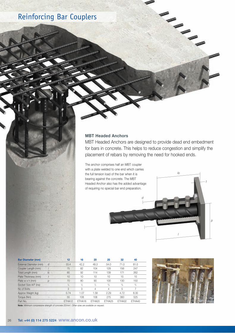
Bar Diameter (mm) 12 16 20 25 32 40
External Diameter (mm) d 33.4 42.2 48.3 54.0 71.0 81.0
Coupler Length (mm) l 75 82 104 129 156 247
Total Length (mm) lo 85 92 114 139 171 262
Plate Thickness (mm) t 10 10 10 10 15 15
Plate w x h (mm) p 70 80 90 100 130 150
Socket Size A/F (ins) 1/21/2
1/25/8
5/83/4
No of Bolts 3 3 4 4 5 7
Approx Weight (kg) 0.74 1.07 1.58 2.29 4.72 8.30
Torque (Nm) 55 108 108 275 360 525
Part No. ETHA12 ETHA16 ETHA20 ETHA25 ETHA32 ETHA40
Note: Minimum compressive strength of concrete 25/mm2. Other sizes are available on request.
MBT Headed AnchorsMBT Headed Anchors are designed to provide dead end embedmentfor bars in concrete. This helps to reduce congestion and simplify theplacement of rebars by removing the need for hooked ends.
26 Tel: +44 (0) 114 275 5224 www.ancon.co.uk
The anchor comprises half an MBT couplerwith a plate welded to one end which carriesthe full tension load of the bar when it isbearing against the concrete. The MBTHeaded Anchor also has the added advantageof requiring no special bar end preparation.
Reinforcing Bar Couplers
Other Ancon ProductsReinforcement Continuity SystemsReinforcement Continuity Systems are anincreasingly popular means of maintainingcontinuity of reinforcement at constructionjoints in concrete. The Ancon Eazistrip re-bendsystem is approved by UK CARES andconsists of pre-bent bars housed within agalvanised steel casing. Once installed, thebars are straightened ready for lapping withslab reinforcement. Ancon KSN Anchors andAncon Starter Bars are cast into a concretewall and accept threaded continuation bars.They easily accommodate long EC2 laplengths and eliminate the need for on-site barstraightening. KSN Anchors minimise rebarcongestion in the wall.
Shear Load ConnectorsAncon DSD and ESD Shear Load Connectorsare used to transfer shear across expansionand contraction joints in concrete. They aremore effective at transferring load and allowingmovement to take place than standard dowels.The range features rectangular box sectionsleeves to allow lateral movement in addition tolongitudinal movement. A range of LockableDowels is available for temporary movementjoints in post-tensioned concrete.
Channel and Bolt FixingsAncon offers a wide range of channels andbolts in order to fix stainless steel masonrysupport, restraints and windposts to structuralframes. Cast-in channels and expansion boltsare used for fixing to the edges of concretefloors and beams.
Punching Shear ReinforcementAncon Shearfix is used within a slab to provideadditional reinforcement from punching sheararound columns. The system is approved byUK CARES and consists of double-headedsteel studs welded to flat rails. Shearfix isdesigned to suit the load conditions and slabdepth at each column using free calculationsoftware from Ancon.
Insulated Balcony ConnectionsAncon’s thermally insulated connectorsminimise heat loss at balcony locations whilemaintaining structural integrity. They provide athermal break and, as a critical structuralcomponent, transfer moment, shear, tensionand compression forces. Standard solutionsare available for concrete-to-concrete, steel-to-concrete and steel-to-steel interfaces.
27
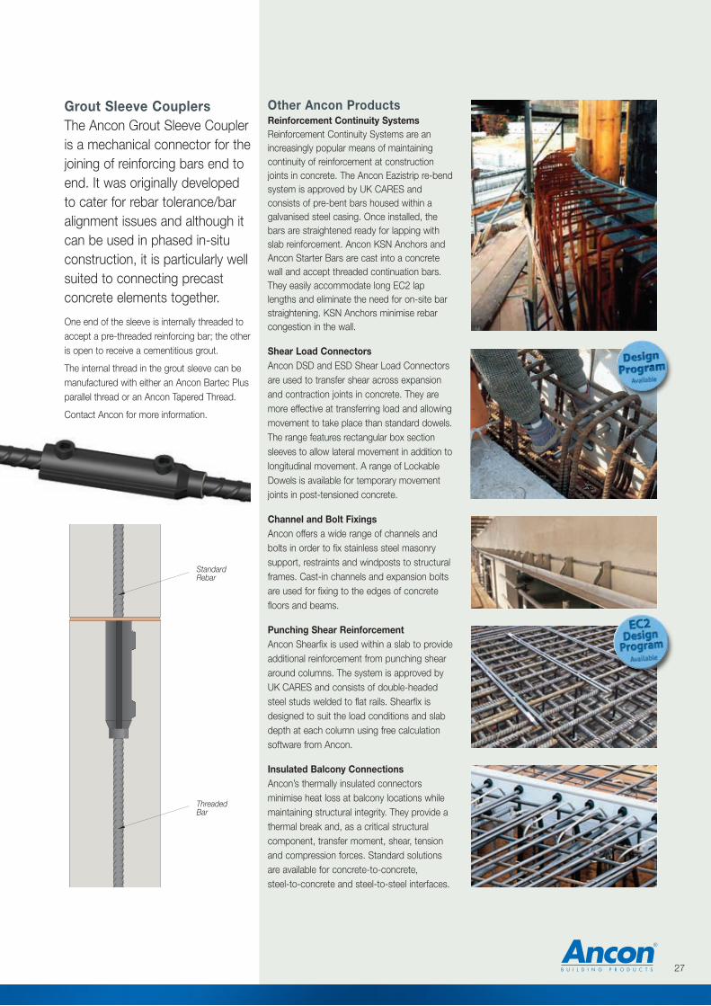
StandardRebar
ThreadedBar
Grout Sleeve CouplersThe Ancon Grout Sleeve Coupleris a mechanical connector for thejoining of reinforcing bars end toend. It was originally developedto cater for rebar tolerance/baralignment issues and although itcan be used in phased in-situconstruction, it is particularly wellsuited to connecting precastconcrete elements together.
One end of the sleeve is internally threaded toaccept a pre-threaded reinforcing bar; the otheris open to receive a cementitious grout.
The internal thread in the grout sleeve can bemanufactured with either an Ancon Bartec Plusparallel thread or an Ancon Tapered Thread.
Contact Ancon for more information.

© Ancon Building Products 2014
These products are available from:
Masonry Support Systems
Lintels
Masonry Reinforcement
Windposts and Parapet Posts
Wall Ties and Restraint Fixings
Channel and Bolt Fixings
Tension and Compression Systems
Insulated Balcony Connectors
Shear Load Connectors
Punching Shear Reinforcement
Reinforcing Bar Couplers
Reinforcement Continuity Systems
Stainless Steel Fabrications
Flooring and Formed Sections
Refractory Fixings
Ancon Building Products98 Kurrajong AvenueMount DruittSydney NSW 2770AustraliaTel: +61 (0) 2 8808 1111Fax: +61 (0) 2 9675 3390Email: [email protected]: www.ancon.com.au
Ancon Building Products2/19 Nuttall DriveHillsboroughChristchurch 8022New ZealandTel: +64 (0) 3 376 5205Fax: +64 (0) 3 376 5206Email: [email protected]: www.ancon.co.nz
Ancon (Schweiz) AGGewerbezone Widalmi 103216 Ried bei KerzersSwitzerlandTel: +41 (0) 31 750 3030Fax: +41 (0) 31 750 3033 Email: [email protected]: www.ancon.ch
Ancon Building ProductsGesmbHPuchgasse 1A-1220 ViennaAustriaTel: +43 (0) 1 259 58 62-0Fax: +43 (0) 1 259 58 62-40Email: [email protected]: www.ancon.at
Ancon GmbHBartholomäusstrasse 2690489 NurembergGermanyTel: +49 (0) 911 955 1234 0Fax: +49 (0) 911 955 1234 9Email: [email protected]: www.anconbp.de
Ancon Building ProductsPresident Way, President ParkSheffield S4 7URUnited KingdomTel: +44 (0) 114 275 5224Fax: +44 (0) 114 276 8543Email: [email protected]: www.ancon.co.ukFollow on Twitter: @AnconUK
Ancon (Middle East) FZEPO Box 17225Jebel AliDubaiUnited Arab EmiratesTel: +971 (0) 4 883 4346Fax: +971 (0) 4 883 4347Email: [email protected]: www.ancon.ae
The construction applications and details provided in this literature are indicative only. In every case, project workingdetails should be entrusted to appropriately qualified and experienced persons.
Whilst every care has been exercised in the preparation of this document to ensure that any advice, recommendations orinformation is accurate, no liability or responsibility of any kind is accepted in respect of Ancon Building Products.
With a policy of continuous product development Ancon Building Products reserves the right to modify product designand specification without due notice.