Embed Size (px)
Citation preview

Reinforced Concrete Analysis and Flexural Design – Factors for
Safety and Strain Comfort
MORGAN STATE UNIVERSITY
SCHOOL OF ARCHITECTURE AND PLANNING
LECTURE II / Fall 2015
Dr. Jason E. Charalambides

Copyright J. CharalambidesCopyright J. Charalambides
Analysis of Reinforced Concrete Beams
Calculation of a beam’s moment capacity:– The triangular beam indicated is made of f`c=4ksi concrete and carries
three (3) #9 rebars of fy=60ksi.• Note that geometry offers itself for calculations regarding the Compression, the
lever-arm, and the depth of “a”.

Copyright J. CharalambidesCopyright J. Charalambides
– We begin by the fundamental assumption that fs=fy (we verify this at a later step) and we calculate the area of steel As:
! 3 #9 rebars give us a total area of 3sq.in
!
“fs” is what we saw as ”ft” earlier = Calculated stress of reinforcement at service loads, fy=specified yield strength of non prestressed reinforcement.
Analysis of Reinforced Concrete Beams
T=As( f y)=3inch2∗60ksi=180kips
Copyright J. CharalambidesCopyright J. Charalambides
– We compute the compression block so that we have C=T: ! Given C=T = 180kips
! The specific geometry of the beam allowed us to generate the formula for C. That can be reversed to solve for a: …which gives us a value of 10.29in.
Analysis of Reinforced Concrete Beams
a=√ 2T0.85∗ f ' c
Note: The above formula is not to be used for any other scenario. It has been produced specifically for this geometric formation

Copyright J. CharalambidesCopyright J. Charalambides
– Verifying our assumption that fs=fy: ! As mentioned earlier, εcu will carry the value of 0.003! c=α/β1…thus c=10.29in/0.85…..= 12.11in
! Using the similar triangles method as seen above…! thus εt is 0.00394 > εty which is fy/Es that is 60ksi/29000ksi yielding a value
of 0.00207 (ACI 318-14 – 21.2.2.1), proving that fs=fyεs =strain in steel (also seen as εt), εty= yield strain.
fs=Calculated stress of reinforcement at service loads, fy=specified yield strength of non prestressed reinforcement.
Analysis of Reinforced Concrete Beams
εt=0.003∗(d−c)c
Copyright J. CharalambidesCopyright J. Charalambides
– Computing the Mn:! We can derive from the geometry that jd=d-(2a/3)
! Per ACI 318-14 Table 21.2.2:
! And the φ being equal to 0.9, yields the result of ΦΜn=285.4 k`
Analysis of Reinforced Concrete Beams
φ=0.9≥0.65+0.25(ε t−ε ty)0.005−ε ty
≥0.65

Copyright J. CharalambidesCopyright J. Charalambides
Flexural Ductility
– That wonderful property of structural materials to bend, crack and yet not break, is one of the possible characteristics of RC.
– When flexural forces surpass the limit My, steel reinforcement continues to elongate. Resistance increases slightly, related to the increase of distance between C and T. That distance increases as the depth of the concrete stress block decreases until the concrete fractures. Although the stress of the steel remains constant, the strain at the point of failure is several times greater than the steel yield strain εty, ..approximately εty=fy/Es ≈.002
Copyright J. CharalambidesCopyright J. Charalambides
Flexural Ductility
– On a section that fractures when the strain of steel is 0.006, if the As was multiplied by a certain factor (let’s say doubled), then the Whitney block would take a similar magnification (double in this case). The strain at the tension could only be 0.003. The stretching of the steel at the range between yield and beam failure would only be 0.001 instead of 0.004 as it was for the section with half as much tension reinforcement.
Copyright J. CharalambidesCopyright J. Charalambides
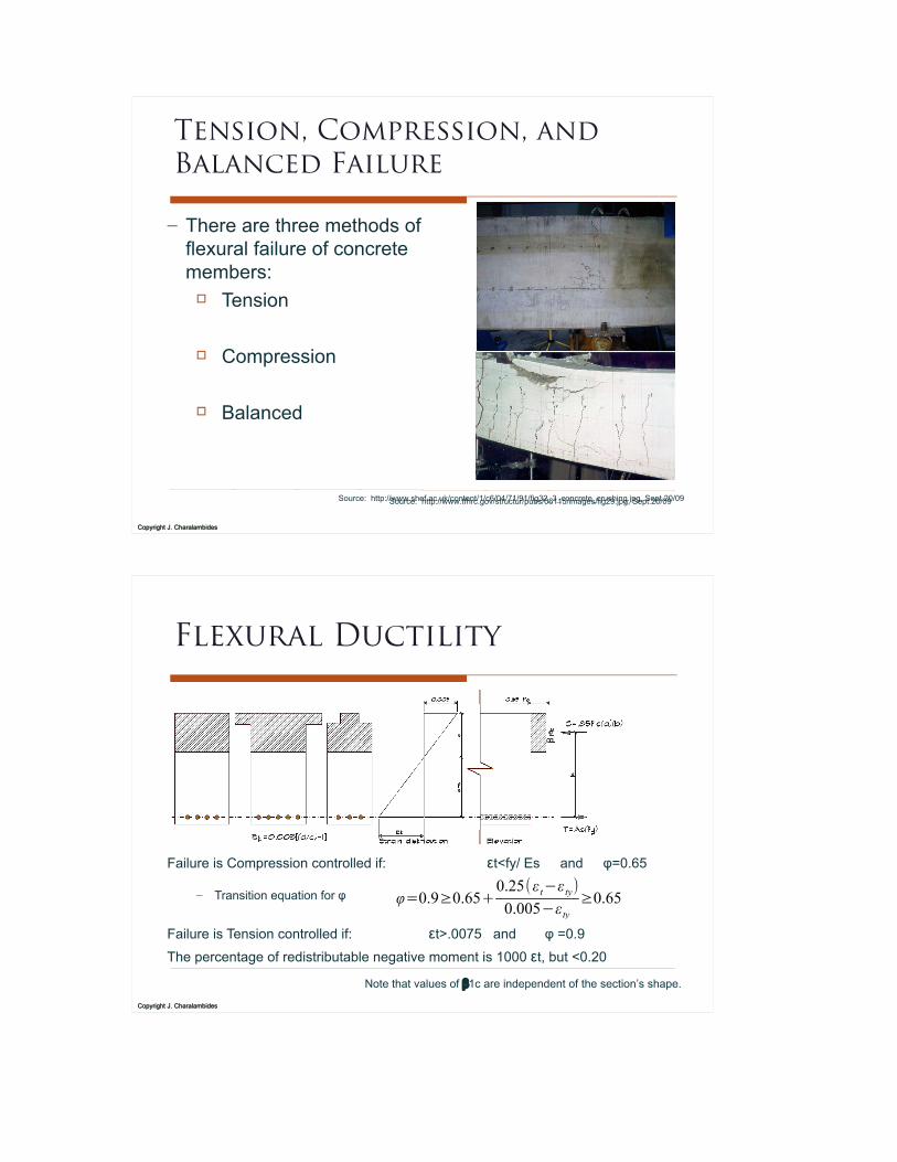
Tension, Compression, and Balanced Failure
– There are three methods of flexural failure of concrete members:! Tension
! Compression
! Balanced
Source: http://www.shef.ac.uk/content/1/c6/04/71/91/fig32_3_concrete_crushing.jpg, Sept.20/09Source: http://www.tfhrc.gov/structur/pubs/06115/images/fig29.jpg, Sept.20/09
Copyright J. CharalambidesCopyright J. Charalambides
Flexural Ductility
Failure is Compression controlled if: εt<fy/ Es and φ=0.65
– Transition equation for φ
Failure is Tension controlled if: εt>.0075 and φ =0.9
The percentage of redistributable negative moment is 1000 εt, but <0.20
Note that values of â1c are independent of the section’s shape.
φ=0.9≥0.65+0.25(ε t−ε ty)0.005−ε ty
≥0.65

Copyright J. CharalambidesCopyright J. Charalambides
Flexural Ductility
The section in the left carries four rebars to counterbalance the compression force. The middle section indicates a T-beam with a larger cross sectional area in compression, and it is set to equilibrium through the application of more tensile rebars. Inversely, the notched section on the right carries less tensile reinforcement.
Note that values of â1c are independent of the section’s shape.
Copyright J. CharalambidesCopyright J. Charalambides
Design Requirements
The capacity reduction “φ” factor also reflects the relative ductility of the cross section at failure expressed in terms of the strain εt as presented by ACI.To determine the value of εt the proportional triangle method can be applied as seen in the diagram. εt=0.003[(d/c)-1]

Copyright J. CharalambidesCopyright J. Charalambides
Design Requirements
The capacity reduction “φ” factor also reflects the relative ductility of the cross section at failure. For tension controlled, ductile, flexural failure at εt>0.005, (i.e 2.5 times larger than εy for Grade 60), φ= 0.90 Failure at εt≤fy/Es is compression controlled, non-ductile, and φ=0.65
0.9 0.77250 t 0.25f y!! "145 f y!
" 0.65
For further details and info, please refer to R. W. Furlong's book: pp 40-41.
φ=0.9≥0.65+0.25(ε t−ε ty)0.005−ε ty
≥0.65
Copyright J. CharalambidesCopyright J. Charalambides
MOMENT REDISTRIBUTION
ACI recognizes that the magnitude of moments at critical locations of a flexural member, estimated through elastic analysis, cannot be totally precise. Therefore, designers are allowed to “redistribute” moment values (from support regions to span) provided that:
– This however is a subject we shall only address at a mere informative level in this class.
Source: R.W. Furlong: Basic Decisions for Designing Reinforced Concrete Structures, Morgan Printing, Austin , TX, Sept. 2003

Copyright J. CharalambidesCopyright J. Charalambides
Standardized ρ Values
*Note: The main effective depth suggests that after As is determined, a cover per ACI guidelines should be determined as well.
To recap and bring to surface a few standardized values:
– A recommended ρMax will be applied when the objective is to minimize the depth of a beam. The εt will be 0.004 and φ will be 0.81.*
– The ρMin is a threshold value that we shall never cross.
– The ρlim is the limit that keeps us within an εt of .005 and ACI 318-14 allows φ=0.9
– The ρ10 is an ideal condition that we should always aim for in order to have a comfortable condition for our designed element and where the εt is 0.010
Copyright J. CharalambidesCopyright J. Charalambides
0.9>0.7+(7250εt−0.25f y)
145− f y>0.65
In Class Example:
Select flexural bars for the section and the required moment and determine the ΦMn, the β1 ratio (ratio of depth of rectangular stress block, a, to the depth to neutral axis c) the distance c and the strain on the extreme fiber of reinforcement εt.

Copyright J. CharalambidesCopyright J. Charalambides
In Class Example:


![[EMPA] Flexural Strengthening of Reinforced Concrete](https://img.dokumen.tips/doc/110x75/577cdab51a28ab9e78a65444/empa-flexural-strengthening-of-reinforced-concrete.jpg)
