Embed Size (px)
Citation preview

75
Rehabilitation of Sunkoshi Small Hydropower Plant (2.6 MK),
Nepal after Sequences of Natural Disaster
Sakunda Ojha
Sanima Hydropower Ltd, Dhumbarai, Kathmandu, Nepal *Email: [email protected]
Abstract- Sunkoshi Small Hydropower Plant (SSHP) is a run-of-river type project constructed in Sunkoshi River located in Sindhupalchowk District of Bagmati zone of Central Development Region, Nepal. The plant started its commercial operation since March 2005. During the year 2014, 2015 and 2016 the plant faced series of natural disaster events; landslide at Jure village on 2 August 2014, earthquake (7.8 magnitude) on 25 April 2015, landslide dammed flood in Sunkoshi River on 11 August 2015 and Glacier Lake Outburst Flood (GLOF) in Sunkoshi River on 5 July 2016. The Jure landslide created 55 m dam across Sunkoshi River. Thus created landslide dammed lake inundated the powerhouse of SSHP for 36 days. About seven million cubic meters of water was reserved in the lake. The event damaged entire powerhouse building, Electromechanical Equipment (EM), tailrace culvert, portion of steel penstock pipe and staff quarter. The rehabilitation works after Jure landslides included strengthening of powerhouse building and tailrace culvert, winding of generators, replacement of electromechanical equipment and portion of penstock pipe and change of transmission line alignment. On 25 April 2015, most of the rehabilitation works were completed. The EM experts were conducting a wet test for power generation when the power-plant was hit by other natural disaster - earthquake of 7.8 Rector Scale. The earthquake and its aftershocks followed by landslide dammed outburst flood of 11 August 2015 damaged headworks structures - formed a cavern of 56.6 m
3 below gravel trap,
collapsed entire powerhouse building and damaged newly installed electromechanical equipment, created several landslides along water way alignment and damaged about 900 m of penstock alignment. Some innovations in designs were introduced such as construction of sliding type saddle supports, bio-engineering combined with civil engineering structures to stabilize landslides, retrofitting of powerhouse building, use of crackamite and rock drill and avoidance of heavy masonry wall and gable wall in powerhouse. After rehabilitation works, the power plant re-operated since 4 January 2016 - after about 18 months. However, the plant was again affected by a Glacier Lake Outburst Flood (GLOF) in Botekoshi River on 5 July 2016.
Indexed Terms- Jure landslide; Earthquake; Glacier Lake Outburst Flood.
I. INTRODUCTION
Sunkoshi Small Hydropower Plant (SSHP) is a run-of-river type project constructed in Sunkoshi
River located in Sindhupalchowk District of Bagmati zone of Central Development Region, Nepal.
The project utilizes the flow of Sunkoshi River that is diverted at about 3.5 km upstream from the
confluence of Sunkoshi and Botekoshi River. The Powerhouse is located at about 300 m downstream
from the confluence of Sunkoshi and Bhotekoshi River. The plant came into operation since March
2005. During the year 2014, 2015 and 2016 the plant faced four major disaster events; landslide at
Jure village on 2 August 2014, earthquake (7.8 magnitude) on 25 April 2015, landslide dammed
flood in Sunkoshi River on 11 August 2015 and Glacier Lake Outburst Flood (GLOF) in Botekoshi
River on 5 July 2016.
INTERNATIONAL JOURNAL OF ENGINEERING TECHNOLOGY AND SCIENCES (IJETS)
ISSN: 2289-697X (Print); ISSN: 2462-1269 (Online) Vol.5 (2) August 2018
© Universiti Malaysia Pahang
DOI: http://dx.doi.org/10.15282/ijets.5.2.2018.1008

S. Ojha/International Journal of Engineering Technology and Sciences 5 (2) (2018)
76
In August 2014, the massive Jure landslide and so formed landslide dammed lake completely
inundated the powerhouse for 36 days. Before the plant could be resumed (after renovation), the
massive earthquake of 7.8 Ricter Scale with its epicenter at Barpak, Gorkha and its subsequent
aftershocks destroyed the powerhouse and penstock alignment of the plant. Furthermore, the massive
flood of August 2015 washed away portion of headworks structures, access road to headworks and
bridge.
II. DATA USED AND METHODOLOGY
Table 1: Different data type and methodology
Data Type Methodology
Damage
estimates
Walk along landslide and landslide dammed lake area and along project alignment
to observe damages and vulnerabilities on structures.
Visual inspection on every components of powerhouse specially the structural
elements (Beam, column, machine floor) to locate level of damages.
Detailed survey of landslide dammed flood and structural components of the plant
to determine tilt/Shift and settlement.
Restoration
works
Installation of new electromechanical equipment, generator winding, testing,
drawing/design of civil structures and retrofitting.
III. RESULTS AND DISCUSSIONS
3.1 Background on Jure Landslide
A massive landslide was triggered at around 02.30 am, local time on Saturday, 2 August 2014 at Jure
village in Sindhupalchowk district in the boarder of Mankha VDC-01 and Ramche VDC-04. The
landslide blocked Sunkoshi River creating a high dam of about 55 m across the river. The back flow
water from this entered Sunkoshi Hydropower Station at about 8:05 am and fully sub-merged the
powerhouse at about 2:30 pm. The water level was maintained at about 840 amsl (which is above the
roof level of powerhouse).
The landslip comprising huge detached rock mass blocked the river forming a natural dam.
The estimated total volume of material in the natural dam was about 60,000,000 m3. Landslide
material formed very low angle about 15 to 20 degrees along upstream and downstream. Since, the
dam material comprised of shattered rock mass (detached blocks and boulders comprising phyllite and
quartzite) covered by cohesive material; the river water could not erode the material. Subsequently,
the flow retained into natural lake, pooling about 3.5 km stretch upstream and reserving about seven
million cubic meters of water.

S. Ojha/International Journal of Engineering Technology and Sciences 5 (2) (2018)
77
Figure 1: Jure Landslide
The landslide dam abruptly breached on 7th
of September 2014 at about 2:35 am resulting
significant draw down in water level allowing most of the water to drain out. The water level draw
observed at Sunkoshi Small Hydropower Plant was from 840 m (as of 19th
august 2014) to 818 m.
The breach appeared to be natural - a response to heavy rainfall, however widening and excavation of
channel on downstream from Nepal Army and erosion from rainfall further enhanced the dam breach.
The flash flood was observed on downstream due to sudden breach of dam but no significant damage
and casualties were found due to this flash flood except damages on dam, undersluice and intake of
Sunkoshi Hydropower Plant (NEA) – a downstream 10 MW plant. The power plant was submerged
for 36 days starting from 2nd of August to 7th of September 2014.
Figure 2: Submergence of Powerhouse
Submerged
Powerhouse

S. Ojha/International Journal of Engineering Technology and Sciences 5 (2) (2018)
78
3.2 Background on Earthquake 2015
A 7.8 magnitude earthquake stroke Nepal on 25 April 2015 at 11:56 am creating a large-scale damage
and many casualties. The epicentre was located at 81 km northwest from Kathmandu on Barpak of
Gorkha District. Hundreds of thousands of households were destroyed rendering people homeless
with entire village and settlement flattened. Strong aftershocks, including a 6.6 magnitude on April
26, 2015 and a 6.7 magnitude on May 16, 2015 created more chaotic situation leading further
damages to the weakened structures and increase in number of casualties. The first aftershocks of 6.7
magnitudes and hundreds of tremors greater than 4.0 magnitudes caused considerable damages to
Sunkoshi Small Hydropower Plant.
Figure 3: Powerhouse floor after earthquake
3.3 Background on Flood of August 2015 and July 2016
Due to the continuous heavy rainfall (August 2015), that lasted for few days a flash flood was
observed in Sunkoshi river. Due to toe cutting by the flash flood and saturated conditions due to
continuous raining, a landslide on stretch of about 35- 40 meters was triggered on the penstock
alignment about 10-15 meters downstream of Thulodhunga area (located 220 m to 420 m downstream
from settling basin). About 2 to 2.5 meters slope had plunged towards river. Few longitudinal cracks
as wide as 50 to 75cm were observed along the road alignment – located 1 m apart from penstock
alignment. The Glacial Lake Outburst Flood (GLOF) in Tibet on 5 July 2016 flooded the tailrace
culvert of Sunkoshi Hydropower Plant. The flood damaged the transmission line and tailrace of the
plant.
3.4 Damages and scenarios of observation
Followings were the major damages observed in the disaster events discussed above:
3.4.1 Damages Due to Jure Landslide
Along with the powerhouse, staff quarter and all the belongings of staff were submerged.
With the abrupt landslide dam breach, gradual draw down on water level was observed. Most of the
water was drained out. Later each element in the periphery of powerhouse and inside the powerhouse
was inspected.

S. Ojha/International Journal of Engineering Technology and Sciences 5 (2) (2018)
79
Figure 4: Views of damaged powerhouse
During the inspection, following observations were made:
The powerhouse and its periphery was deposited with debris (sand) ranging from 1.5m to 2.9m
depth
The Guard post was also partially buried with silt deposition.
Areas around transformers were damp, saturated and filled by silt.
Cracks were observed on the walls of powerhouse.
The transformer outside the powerhouse was partially buried by siltation.
About 65m of penstock after bifurcation was buried by silts.
Machines (generator, turbines, governors, gates) were buried under Sand/Silt deposition.
Sand/Silt deposition depth inside powerhouse were; Machine hall: about 1.5m to 3.0 m, Service
transformer room: about 1 m, Excitation transformer room: 1m, Breaker room: 1.5m, Control
room: 1m. Few cracks were observed on machine hall’s walls.
Trusses, purling, CGI sheet and other roofing elements had completely collapsed, damaged and
unusable.
About 0.7m to 1.2m of silt/sand was deposited on top of control room slab and toilet slab.
The panel boards, cable and other electrical items were damaged.
The crane inside the powerhouse was damaged.
Figure 5: Collapsed Truss, Roof and Brick wall
Tailrace culvert was filled with silt/sand up to 0.4m to 1.5m in thickness.
About 30 cm debris was deposited inside the staff quarter.
S. Ojha/International Journal of Engineering Technology and Sciences 5 (2) (2018)
80
Table 2: Total loss due to Jure landslide
Description of work Amount
(USD)
Remark
Electricity supply close due to shutdown of power
plant for a period of one year 580,000.00
Reference from F/Y
2012/13 record
Damage of Electromechanical Equipment in
powerhouse including switchyard
550,000.00
Cost of EM Equipment as
on March 2005
Transmission line 12 number of towers with wire and
Lighting Arrester
34,765.53 As on March 2005
Permanent building (powerhouse house building,
staff quarter and tailrace)
183,750.00 As on March 2005
Penstock - Glass Fibre Reinforced Plastic Pipe (GRP) 36,000.00 Swip way by flood
Penstock Pipe – steel pipe 213,750.00 As on March 2005
Total 1,598,265.53
In addition to this the permanent/ direct losses are as follows:
Incurred interest on bank loan due for the period of one year 0.12 million
Staff Salary, insurance and other expenses 0.10 million
Total 0.22 million (USD)
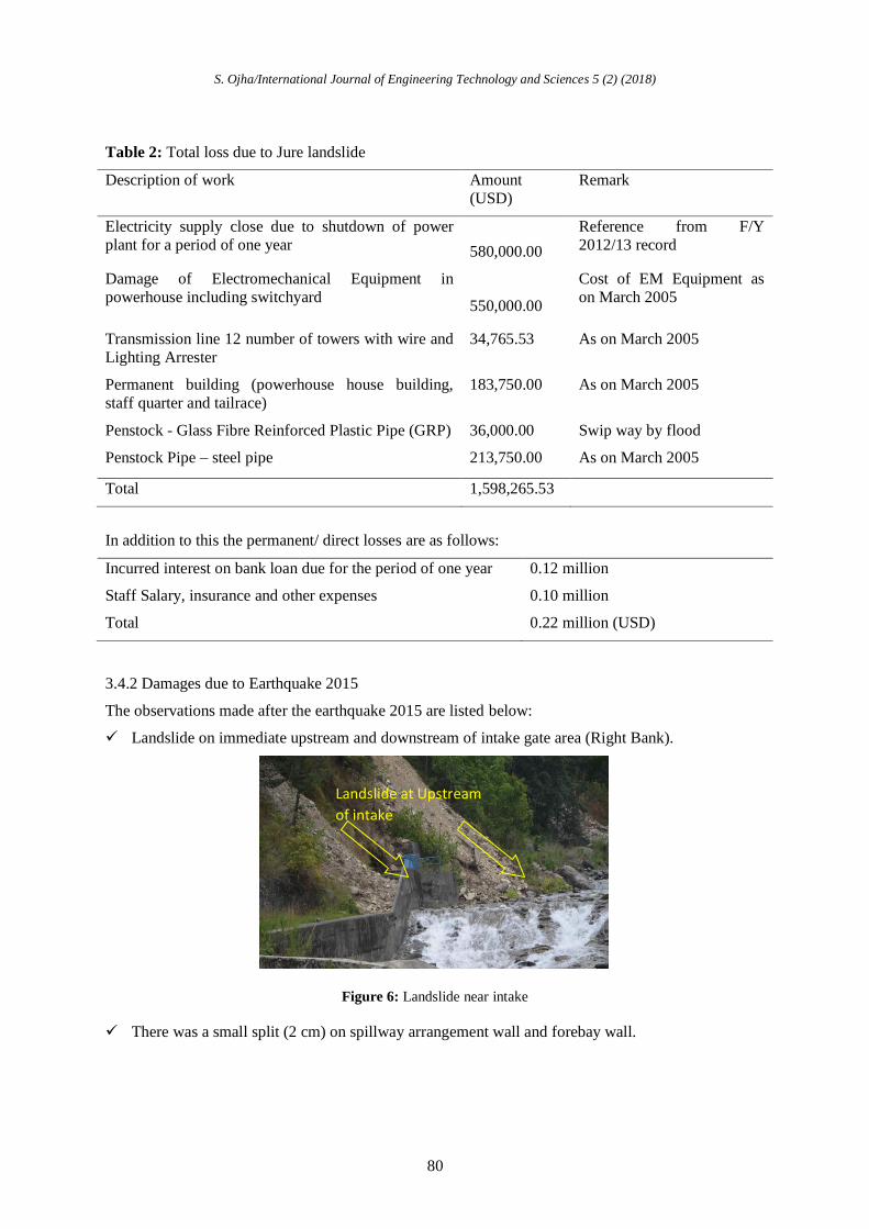
3.4.2 Damages due to Earthquake 2015
The observations made after the earthquake 2015 are listed below:
Landslide on immediate upstream and downstream of intake gate area (Right Bank).
Figure 6: Landslide near intake
There was a small split (2 cm) on spillway arrangement wall and forebay wall.
Landslide at Upstream
of intake
S. Ojha/International Journal of Engineering Technology and Sciences 5 (2) (2018)
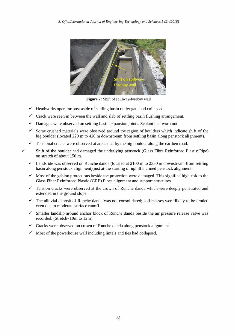
81
Figure 7: Shift of spillway-forebay wall
Headworks operator post aside of settling basin outlet gate had collapsed.
Crack were seen in between the wall and slab of settling basin flushing arrangement.
Damages were observed on settling basin expansion joints. Sealant had worn out.
Some crushed materials were observed around toe region of boulders which indicate shift of the
big boulder (located 220 m to 420 m downstream from settling basin along penstock alignment).
Tensional cracks were observed at areas nearby the big boulder along the earthen road.
Shift of the boulder had damaged the underlying penstock (Glass Fibre Reinforced Plastic Pipe)
on stretch of about 150 m.
Landslide was observed on Runche danda (located at 2100 m to 2350 m downstream from settling
basin along penstock alignment) just at the starting of uphill inclined penstock alignment.
Most of the gabion protections beside toe protection were damaged. This signified high risk to the
Glass Fiber Reinforced Plastic (GRP) Pipes alignment and support structures.
Tension cracks were observed at the crown of Runche danda which were deeply penetrated and
extended in the ground slope.
The alluvial deposit of Runche danda was not consolidated; soil masses were likely to be eroded
even due to moderate surface runoff.
Smaller landslip around anchor block of Runche danda beside the air pressure release valve was
recorded. (Stretch~10m to 12m).
Cracks were observed on crown of Runche danda along penstock alignment.
Most of the powerhouse wall including lintels and ties had collapsed.
Shift on spillway-
forebay wall

S. Ojha/International Journal of Engineering Technology and Sciences 5 (2) (2018)
82
Figure 8: Wall Collapse on Riverside
Vertical crack were observed on edges of the tie beam along northern and southern side of
powerhouse. These cracks were developed throughout the depth of the beam.
Significant concrete cracks were observed along with deformed bar observed on all hillside
columns at corbel level (about 7-8cm crack width).
Cracks were observed on riverside beam- column connection.
Figure 9: Crack on Beam - Column
Cracks were observed on the bottom part of column. Prominent cracks were visible on all
riverside columns (about 20-30cm above machine floor level).
Damages were seen at the excitation transformer and service transformer due to falling of wall.
Some cracks were observed on machine floor.
The partition walls on control room, breaker room, service transformer room and store room were
completely damaged.
Toilet roof slab and wall had completely grounded.
Shift on transformer was observed (~5cm) however the foundation was intact.
No physical damages were observed on transmission line after the first quake; however, after the first
aftershocks some towers and 1200 m of conductors were damaged. Beside this, there were some
Cracks in columns floor joint
indicating instability
Cracks in Beam-Column.
Cracks are elongated and
deeply penetrated

S. Ojha/International Journal of Engineering Technology and Sciences 5 (2) (2018)
83
landslips along the transmission line towers route and hence protection work were required. Some of
the towers had to be relocated during restoration work.
Table 3: Total loss due to Earthquake
Description Loss Amount (USD)
Diversion Weir 696.00
Intake 22,678.08
Inlet Culvert and Gravel trap 43,191.82
Settling basin, flushing canal and forebay works 30,414.33
Penstock (CH +000 to 0+500) 51,089.11
Penstock (CH 1250 to 2547) 15,687.28
GRP and Accessories 86,370.33
Powerhouse 73,047.25
Total 323,174.30
3.4.3 Damage due to flash flood
A new landslide was observed about 15m downstream from Thulodhunga area (located 220 m to 420
m downstream from settling basin along penstock alignment). A wide open crack (about 50 to 75 cm
wide) was observed along the road alignment. About 2 m of slope had plunged towards the river. The
landslide was triggered due to sudden rise in Sunkoshi River due to flash flood which resulted in toe
cutting. In addition, high precipitation caused saturation of soil and loss of shear strength. Stone
masonry wall beside the road and plum concrete wall at the toe had collapsed. Pool of boulders were
observed about 20m upstream from the toe of the landslide which will behave as spur and protect the
exact downhill of Thulodhunga.
Figure 10: Crack on Beam - Column
3.5 Restoration works carried out
The rehabilitation works after Jure landslides included strengthening of powerhouse building and
tailrace culvert, winding of generators, replacement of electromechanical (EM) equipment and portion
of penstock pipe and change of transmission line alignment. On 25 April 2015, most of the
rehabilitation works were completed. The EM experts were conducting a wet test for power

S. Ojha/International Journal of Engineering Technology and Sciences 5 (2) (2018)
84
generation when the power-plant was hit by other natural disaster - earthquake of 7.8 Rector Scale.
The rehabilitation works after Jure landslide and earthquake are;
3.5.1 Installation of Electromechanical Equipment
Most of the electro-mechanical equipment that were damaged by Jure flood was changed while some
equipment such as generator was used after maintenance.
Figure 11: Winding of Generator
Figure 12: Dry Test
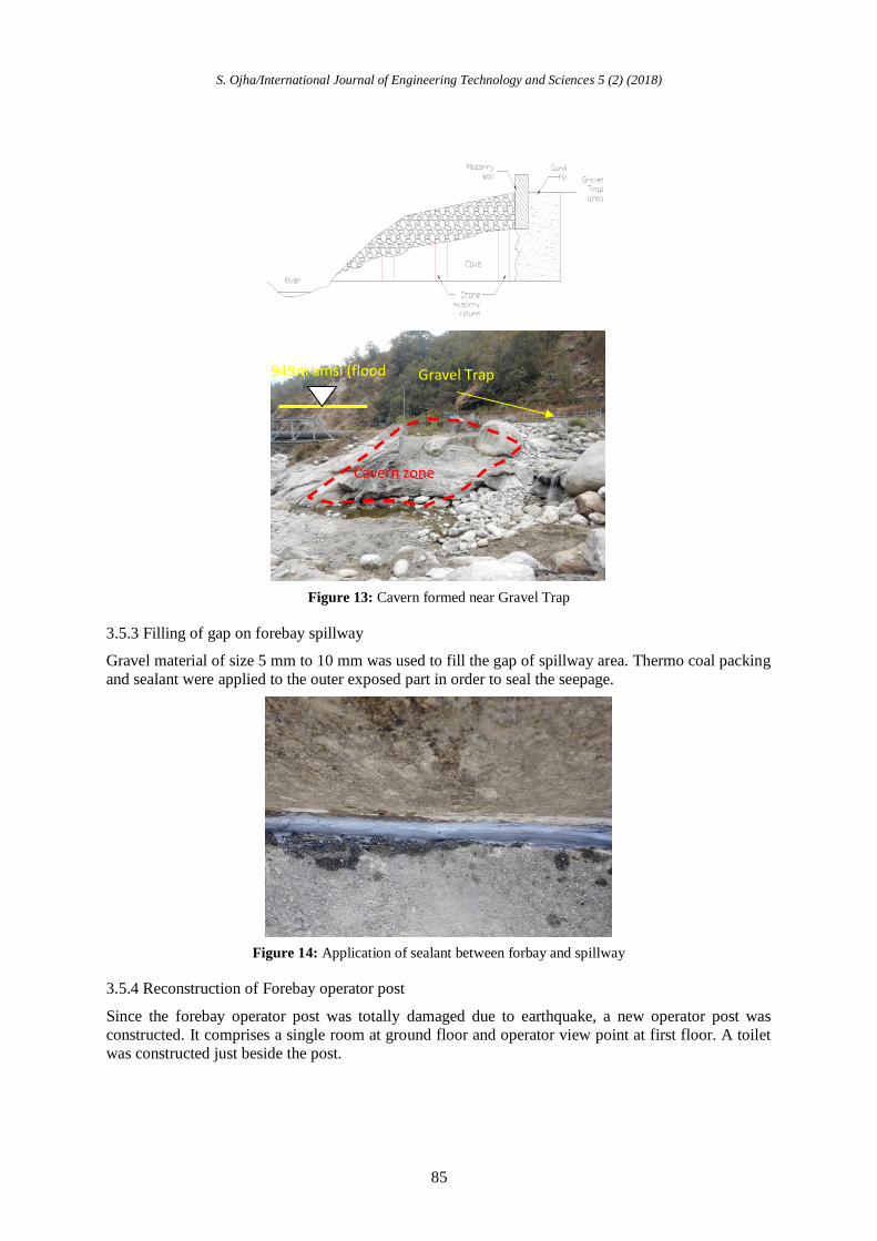
3.5.2 Filling of gravel trap cavern
After the flow was diverted to the intake, a big cavern was observed under the gravel trap area. The
possible cause of the formation of this cavern could be the flash flood that occurred during 2nd
week
of August 2015. The flood level had reached an elevation above 949 m. Due to high energy gradient
available during the flash flood, the larger boulders (1-1.5m dia) in the surface dislocated and the
packing stones of the core washed away. This has caused formation of a hanging structure which
measures about 10 m width and about 15m in length. The approximate volume of the cavern was
56.6m3. Following were the remedial measures adopted:
Since the cavern was hanging, there was high chance of its crumbling. For safety, a stone masonry
wall (1:4) 0.60m wide X 0.6m breadth was constructed to support the hanging cave. The inner side of
the cave was packed with dry stone in layers. Flat shape stones was used and round stones were
shaped to give rough rectangular face. This reduced chances of rolling of stones. Plum concreting was
done in the outer face of cavern (about 1m from face of cavern). The pool outside of the cave was
filled with at least 2m boulders using excavators
S. Ojha/International Journal of Engineering Technology and Sciences 5 (2) (2018)
85
Figure 13: Cavern formed near Gravel Trap
3.5.3 Filling of gap on forebay spillway
Gravel material of size 5 mm to 10 mm was used to fill the gap of spillway area. Thermo coal packing
and sealant were applied to the outer exposed part in order to seal the seepage.
Figure 1 4: Application of sealant between forbay and spillway
3.5.4 Reconstruction of Forebay operator post
Since the forebay operator post was totally damaged due to earthquake, a new operator post was
constructed. It comprises a single room at ground floor and operator view point at first floor. A toilet
was constructed just beside the post.
Cavern zone
949m amsl (flood
level) Gravel Trap

S. Ojha/International Journal of Engineering Technology and Sciences 5 (2) (2018)
86
Figure 15: Forebay operator’s post – under construction
3.5.5 Reconstruction of Headworks quarter
Mud mortar wall was reconstructed without disturbing the existing roof to reinstate the quarter. Other
works such as drain management, replacement of damaged doors and windows, construction of toilet
and plastering of wall were performed.
Figure 16: Headworks operator’s camp
3.5.6 Big Boulder area (Thulo Dhunga)
The movement of big boulder located in sinking zone (located 220 m to 420 m downstream from
settling basin along penstock alignment) had ruptured the GRP. The damaged GRP section was
replaced with mild steel penstock pipe. About 1 m of big boulder was trimmed using Crackamite.
The damaged section of GRP from Ch 0+238.944 m to Ch 0+ 410.223 m has been replaced with
175.83 m mild steel pipe. The new alignment consists of 4 anchor blocks and 29 saddle supports. Two
of the anchor blocks are buried and remaining two are exposed to surface. Out of total 25 saddle
supports, 9 are free movable type to compensate the probable land movement and remaining 20 are of
normal type. About 44 tons of pipes was consumed in order to reinstate the waterways. The replaced
pipe consists of single expansion joint at anchor block 2 and 4 bends at each anchor block.
S. Ojha/International Journal of Engineering Technology and Sciences 5 (2) (2018)
87
Figure 17: Big boulder after trimming
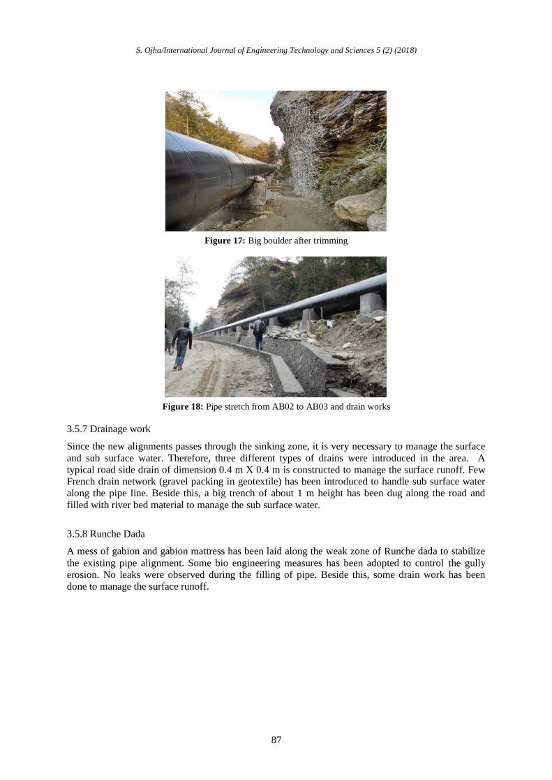
Figure 18: Pipe stretch from AB02 to AB03 and drain works
3.5.7 Drainage work
Since the new alignments passes through the sinking zone, it is very necessary to manage the surface
and sub surface water. Therefore, three different types of drains were introduced in the area. A
typical road side drain of dimension 0.4 m X 0.4 m is constructed to manage the surface runoff. Few
French drain network (gravel packing in geotextile) has been introduced to handle sub surface water
along the pipe line. Beside this, a big trench of about 1 m height has been dug along the road and
filled with river bed material to manage the sub surface water.
3.5.8 Runche Dada
A mess of gabion and gabion mattress has been laid along the weak zone of Runche dada to stabilize
the existing pipe alignment. Some bio engineering measures has been adopted to control the gully
erosion. No leaks were observed during the filling of pipe. Beside this, some drain work has been
done to manage the surface runoff.

S. Ojha/International Journal of Engineering Technology and Sciences 5 (2) (2018)
88
Figure 19: Landslide Stabilization at Runche Dada
3.5.9 Powerhouse
After the Jure landslide, debris deposited around and inside the powerhouse was removed. Damaged
roof truss, roof sheeting and gutter were completely changed. Damaged electromechanical parts and
machinery were replaced. Powerhouse was further damaged due to major earthquake of 26 April 2015
and 16 May 2015. The damaged columns were initially injected with epoxy grout to fill up the voids
developed on the cracks. Later, a jacket concrete section of 150 mm with additional steel lining were
provisioned as a retrofitting measure. On the damaged columns of hillside, for the damages just above
the corbel level, an ISMB 200 was arranged on each column.
Figure 20: ISMB on damaged column and stiffening truss node
Most of the powerhouse walls including the interior partition wall were damaged due to earthquake.
Weak wall were manually dismantled to reduce the probable risks. Later, CGI sheeting was done to
fence the outer wall. The interior walls were limited to a height of about 1.5 m.

S. Ojha/International Journal of Engineering Technology and Sciences 5 (2) (2018)
89
Figure 21: Grouting work epoxy mortar to fill the crack before injection of grout) on powerhouse
Figure 22: Concrete Jacketing on columns
IV. CONCLUSION
4.1 Innovation and lesson learnt
4.1.1 Sliding Type Saddle
The penstock alignment in Ch 0+200 is located in sinking zone. The data observed shows about 70
cm movement in 10 years of time period. The damaged GRP located in this section was replaced by
exposed steel penstock. To cope up the challenge of moving landmass and big boulder, a sliding type
saddle was proposed. This mechanism is assumed to incorporate the probable movement of landmass
by sliding its two units over each other keeping the alignment intact. Control point on each saddles of
this type has been established. This is helpful to observe any movement in due course of time.
Figure 23: Typical Sliding saddle

S. Ojha/International Journal of Engineering Technology and Sciences 5 (2) (2018)
90
4.1.2 Avoid Heavy masonry wall and Gable wall in Powerhouse
Observing the scenario of powerhouse after the earthquake, heavy masonry wall has to be avoided in
powerhouse wall. If not, strip beams have to be introduced to decrease the width by height ratio.
Beside this, it is not recommended to use gable wall, specially a heavier one. This is very prone to
damage even in milder tremors. It is suggested to fill up the space with lighter material like plain
sheet.
Figure 24: Exterior view of powerhouse after CGI fencing
4.1.3 Epoxy Grouting
This technique has been used to fill up the cracks/micro cracks observed in RCC structure due to
earthquake.
4.1.4 Rock drilling and splitting using Crackamite
Crackamite was used to break/split the desired portion of big boulder existed in penstock alignment.
Crackamite is a non explosive silent cracking agent that expands after its application on drill holes.
With the completion of aforementioned restoration work, the power plant successfully completed its
testing and started its commercial operation from January 2015.
V. ACKNOWLEDGEMENT
The author is grateful to Sanima Hydropower Ltd. for providing necessary facilities and Mr. Arun
Kumar Ojha for motivation to conduct this work.
REFERENCES
SHL 2015. A Report on Damage to SSHP from the Earthquake – 2015 and Jure Landslide – 2014