Embed Size (px)
Citation preview

REHABILIATION OF BRIDGE NO. 05491
BAILIWICK ROAD OVER THE BYRAM RIVER
GREENWICH, CONNECTICUT
STATE PROJECT NO. 56-299
TOWN PROJECT NO. 06-44
PRELIMINARY ENGINEERING REPORT
(ROADWAY DESIGN REPORT)
OCTOBER 2011
Prepared By:
Dewberry-Goodkind, Inc.
59 Elm Street, Suite 101
New Haven

Preliminary Engineering Report
Rehabilitation of Bridge 05491
Bailiwick Road over Byram River
Greenwich, Connecticut
TOC-1
Table of Contents
Description Page
Foreword 1
1. Project Description 1
2. Geometric Details 2
3. Traffic Control 4
4. Substructure and Superstructure Evaluations 5
5. Hydrology, Hydraulic and Scour Evaluations 6
6. Preliminary Foundation Report 8
7. Alternate Transportation Modes 9
8. Rights of Way 9
9. Noise/ Air Impacts and Design Features 9
10. Drainage and Permitting 9
11. Utilities 10
12. Landscaping 10
13. Construction Cost Estimate 10
14. Summary and Conclusions 10

Preliminary Engineering Report
Rehabilitation of Bridge 05491
Bailiwick Road over Byram River
Greenwich, Connecticut
TOC-2
Table of Contents
Appendix A – Photos
Appendix B – Design Elements Tables
Appendix C – Plans and Profiles
Appendix D – Cost Estimates
Appendix E – References
Appendix F – Bridge Sketches

Preliminary Engineering Report
Rehabilitation of Bridge 05491
Bailiwick Road over Byram River
Greenwich, Connecticut
1
Report
FOREWORD
For this preliminary engineering phase of the rehabilitation of the Bailiwick Road Bridge over
Byram River (BIN 05491), various technical investigations have been conducted concurrently:
• A Preliminary Hydraulic Findings and Qualitative Scour Assessment Memorandum,
submitted in August 2011, summarized the results of the Hydraulics Analysis and
provided a qualitative Scour Assessment.
• A Structure Type Study Report, submitted in October 2011, summarized the findings of
bridge rehabilitation and replacement alternatives.
• A Preliminary Foundation Report, submitted in October 2011, summarized the findings
of substructure investigations and assessed the condition and capacity of the existing
foundation soils to support the proposed and rehabilitated bridge.
This Preliminary Engineering Report primarily focuses on elements which pertain to the
approach roadway design, but also includes a brief summary of various important factors and
findings contained in the aforementioned reports.
1. PROJECT DESCRIPTION
Bridge No. 05491 carries Bailiwick Road, an urban local road, over the Byram River in the
Town of Greenwich (Town), Connecticut. The bridge is located approximately fifty-five feet
west of the intersection of Bailiwick Road and Riversville Road (refer to Sheet 12, Appendix C)
and provides the only official public access to a community of approximately 200 residents. The
Average Annual Daily Traffic (AADT) on the bridge is estimated at 590 vehicles (Year 2008)
based on information made available from the Town.
The 32 foot long (chord length) single span bridge carries one lane of vehicular traffic in the
eastbound and westbound directions over a roadway with a 27 foot curb-curb width. In addition,
the bridge carries an approximately 5’-0” wide grass walkway along the south fascia. The bridge
is located within the limits of a slightly curved horizontal roadway alignment and a crest vertical
curvature. According to Connecticut Department of Transportation (ConnDOT) records, the
bridge was originally constructed in 1970.
During a major storm event on April 15, 2007, the Bailiwick Road Bridge sustained significant
damage as a result of the Byram River overtopping the bridge. The damage included the
detachment of the north (i.e. upstream) parapet and rail system from the bridge structure and
failure of the bituminous concrete pavement resulting in the closure of the bridge. The Town was
able to detour traffic via a private roadway belonging to Bailiwick Club. Subsequently, the Town

Preliminary Engineering Report
Rehabilitation of Bridge 05491
Bailiwick Road over Byram River
Greenwich, Connecticut
2
was able to reopen the bridge by installing temporary precast concrete barriers along the fascias
to act as parapets and reconstructing the roadway pavement over the arch bridge. The Town has
since repaired (in kind) the storm damaged parapet with funding available from the Federal
Emergency Management Agency (FEMA). It should be noted that neither the original parapets
nor the repaired parapets have steel reinforcing within. Without steel reinforcing, the parapets
are likely to continue to fall apart over time and with further bridge overtopping events.
Refer to Photos 1 to 5 in Appendix A for photos of existing bridge structure and approaches. A
general-plan, elevation and cross section of the existing bridge is depicted as Sketch 1 in
Appendix F.
2. GEOMETRIC DETAILS
The proposed project will begin at Sta. 102+60, approximately 275’ west of the bridge. The
project will end at Sta. 106+81, approximately 100’ east of the bridge. The portion of Bailiwick
Road within the described project limits is located on a curvilinear alignment.
Bailiwick Road is classified as an “Urban Local Street”. The 2003 Connecticut Department of
Transportation (ConnDOT) Highway Design Manual (HDM) recommends a travel lane width of
10’to11’ and a shoulder width of 2’ to 4’for Urban Local Streets in Suburban areas (Refer to
Appendix E). The existing roadways within the project limits do not meet these criteria.
The width of the roadway on the bridge will be widened to accommodate two 11 ft lanes and 3 ft
shoulders on each side. The roadway approach on the west side will be tapered to match the
widened roadway on the bridge. Any proposed widening will be tapered and the taper geometry
will be designed to meet existing roadway width beyond the immediate vicinity of the bridge.
(Refer to Sheet No. 1, Appendix C).
Three bridge alternatives were examined in the Structure Type Study Report. The three
alternatives had identical horizontal alignments, but differing vertical alignments.
1. Alternative 1- Bridge replacement. The roadway profile was raised by 14” above the
existing ground at the east abutment. Refer to sheet nos. 2 to 5 (Appendix C).
2. Alternative 2- Bridge rehabilitation with addition of relief culverts. The roadway
profile was raised 14” above the existing ground at the crown of the bridge. Refer to
sheet nos. 6 to 9 (Appendix C).
3. Alternative 3- Bridge rehabilitation with the lowering of the west approach roadway by
6” below existing ground. Refer to sheet nos. 10 and 11 (Appendix C).
Alternative 3 was not investigated further for the following two reasons:
1. The preliminary hydraulic analysis indicated no significant hydraulic benefits by
lowering of the profile on the west approach roadway.

Preliminary Engineering Report
Rehabilitation of Bridge 05491
Bailiwick Road over Byram River
Greenwich, Connecticut
3
2. Lowering of the road results in a substandard sag curve on the west approach with the
“K” value reducing from 34 (existing condition) to 30, both of which are less than the
minimum design standard requirement of 34.
Since Alternative 3 was not investigated further, only the roadway profiles, which are attached in
Appendix C, were developed for this alternative.
The portion of Bailiwick Road from Sta. 102+60 to Sta. 106+81 will be reconstructed due to the
poor condition of the existing pavement. Since the vertical alignment of Bailiwick Road will be
revised, the portion of Riversville Road from Sta. 200+45 to Sta. 201+70 will be reconstructed to
obtain desirable grading of the intersection. Alternative 1, as shown in Sheet Nos. 2 and 4
(Appendix C), consists of two 11 ft lanes with no shoulders. The roadway is widened from Sta.
104+00 to Sta. 104+90 to accommodate a 3 foot shoulder on each side of the travel lane and the
shoulders continue all the way to the intersection with Riversville Road.
Alternative 2, as shown in Sheet Nos. 6 and 8 (Appendix C), consists of two 11 ft lanes and no
shoulders. The eastbound lane is widened from Sta. 104+00 to Sta. 104+90 to accommodate a 3
foot shoulder, which continues all the way to the intersection with Riversville Road. The
westbound lane is widened from Sta. 104+00 to Sta. 104+90 to accommodate a 3 foot 7 inch
wide shoulder at Sta. 104+90 and thereafter a variable width shoulder is provided all the way to
the intersection with Riversville Road. A Three (3) inch thick concrete block pavers are proposed
to fill the area on the bridge between the roadway and the south parapet as depicted in Sheet No.
3 (Appendix F). The areas outside the limits of the block pavers will be graded and seeded. A
sidewalk was not considered due to the absence of a sidewalk system within or in the vicinity of
the project limits.
The pavement in Alternative 1 will be full depth Hot Mix Asphalt (HMA) from Sta. 102+60 to
Sta. 104+00, 2 inch bituminous overlay on 8 inch concrete pavement from Sta. 104+00 to Sta.
105+30.50 and full depth HMA from Sta. 105+89.60 to Sta. 106+81. A 2 inch HMA was added
to 8 inch concrete pavement in Alternative 1 so that the pavement will look uniform on both the
bridge and the roadway approaches within the project limits. Refer to Sheet Nos. 3 and 5,
Appendix C. The pavement in Alternative 2 will be full depth HMA from Sta. 102+60 to Sta.
104+00, 8 inch concrete pavement from Sta. 104+00 to Sta. 106+09 and full depth HMA from
Sta. 106+09 to Sta. 106+81. Refer to Sheet Nos. 7 and 9, Appendix C. The purpose of a concrete
pavement is to fortify the pavement structure and prevent its failure in the event of future
overtopping events. While there is no feasible way to rebuild the bridge structure to avoid all
potential flooding events, the concrete pavement structure will ensure that the roadway will be
intact once the flood waters recede.
An 8 inch concrete pavement will be provided between Sta. 102+60 and Sta. 106+09, if
Alternate 3 is pursued, so that the sag portion of the lowered west approach roadway would be
able to carry the flood water without any failure of the pavement structure. A full depth HMA
pavement will be provided between Sta. 106+09 and Sta. 106+81. Refer to Sheet Nos. 10 and 11,
Appendix C for details.

Preliminary Engineering Report
Rehabilitation of Bridge 05491
Bailiwick Road over Byram River
Greenwich, Connecticut
4
The pavement on Riversville Road will be full depth HMA in all the three alternatives.
The design parameters recommended for this project are listed below. A comparison of existing
and proposed roadway design elements with the current Design Standards specified in the
ConnDOT HDM is tabulated in the Design Elements Table in Appendix B:
a. Design Traffic Volume: 590 AADT, November 2008 (Source: Town of Greenwich)
b. Design Classification: Urban Local
c. Design Speed: 30 mph
d. Posted Speed: 25 mph
e. Minimum and Maximum Grade: 0.5 and 11.0%
f. Maximum Superelevation: 4%
g. Minimum Stopping Sight Distance: 200 ft.
h. Lane Width: 10 - 11 ft.
i. Shoulder Width: 2 - 4 ft.
j. Pavement Type and Composition: Asphalt (Class 1 and Class 4)
l. Climbing Lanes: Not Applicable
As summarized in the Design Element Table, the following roadway elements are considered to
be substandard features in both Alternatives 1 and 2:
1. Shoulder Width on Approach Road
Currently there is no shoulder on both the approach roadways. A design exception will be
sought for lack of shoulder on approach road as this is a bridge rehabilitation project and
major approach roadway rework is not within the scope of this work. Existing substandard
conditions will be improved to the extent reasonable and feasible in design development.
2. Sidewalk Width
Currently there is no sidewalk on Bailiwick Road. A design exception will be sought for the
lack of a proper sidewalk on the road as major roadway section modifications are not
warranted for this bridge remediation project. Existing substandard conditions will be
improved to the extent reasonable and feasible without involving right of way impacts.
3. TRAFFIC CONTROL
The layout of the proposed intersections located within the project limits, traffic management
plans and illumination treatments at bridge are described below.
a. Intersection Configuration – There is one (1) intersection present within the project limits:
• Intersection of Bailiwick Road and Riversville Road – This is a three-legged intersection.
Each of the intersecting streets is a two lane roadway. Only eastbound movement from
Bailiwick Road is controlled by a STOP sign. No changes are anticipated to the existing
intersection configuration. Refer to Photo 5, Appendix A.

Preliminary Engineering Report
Rehabilitation of Bridge 05491
Bailiwick Road over Byram River
Greenwich, Connecticut
5
b. Existing and projected turning volumes- Data not available
c. Intersection Capacity Analysis – Not Applicable
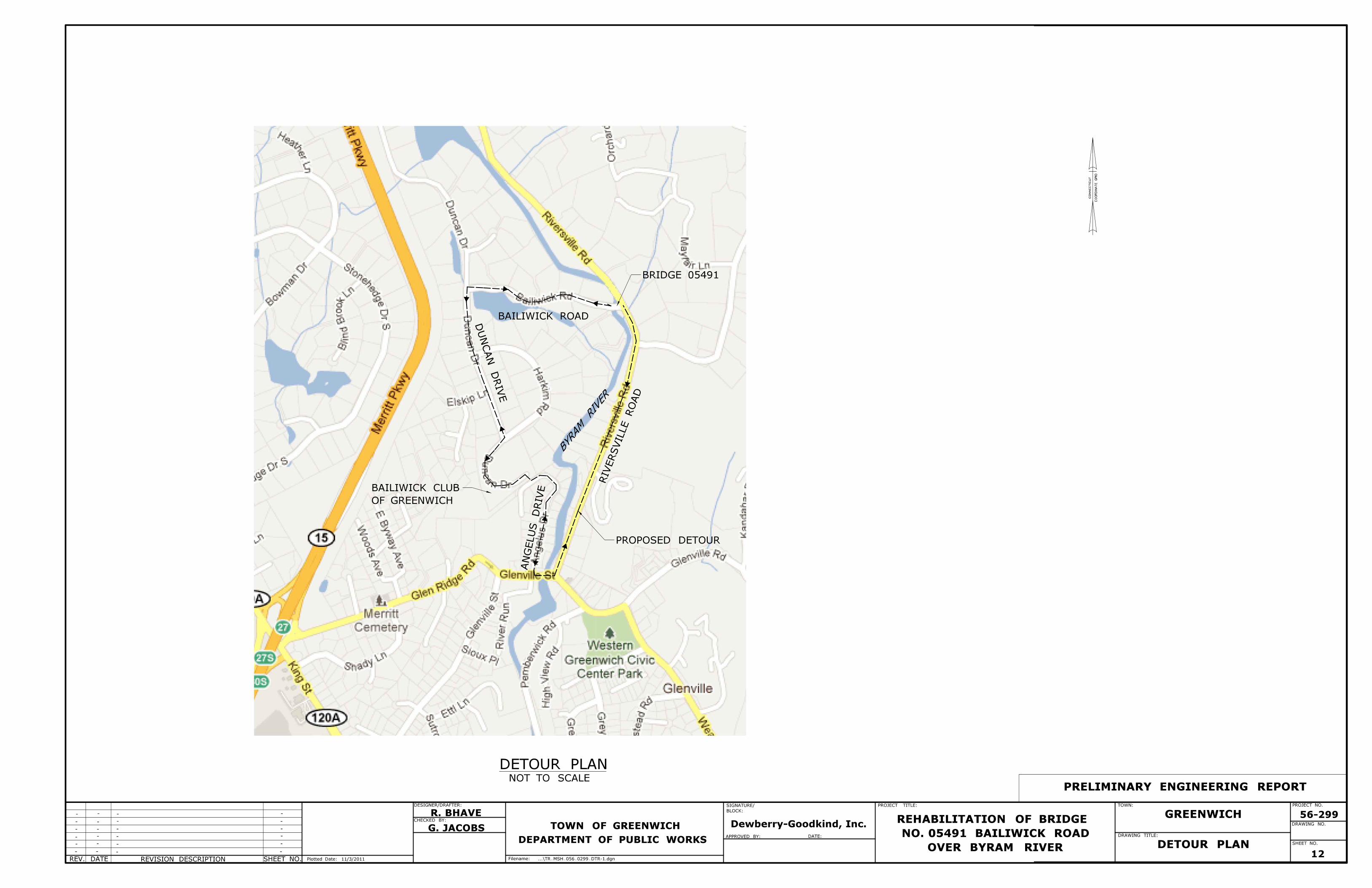
d. Traffic Management Plan – The Bailiwick Road Bridge will be closed during construction.
The vehicular traffic will be detoured via a private roadway/driveway belonging to Bailiwick
Club. An agreement may need to be developed between the Town and Bailiwick Club to
utilize the private road/driveway as a detour route during construction. The vehicular traffic
will be routed via Duncan Drive, Angelus Drive, Glenville Street and Riversville Road as
depicted in the Detour Plan (Sheet No. 12, Appendix C). All bicycle and pedestrian traffic
will follow the same detour path and hence no separate detour for bicycle and pedestrian
traffic will be designed.
e. Illumination – Existing lighting will be replaced in kind unless otherwise directed by the
town and public outreach process. No formal illumination analysis will be conducted.
f. Traffic Signs – Existing signs impacted by the construction will be reset to their original
locations after the construction activities are completed.
4. SUBSTRUCTURE AND SUPERSTRUCTURE EVALUATION
A Structure Type Study Report was submitted in October 2011 under separate cover. The
following narrative is a summary of aforementioned report. Please refer to the complete
Structure Type Study Report for further information.
The goals of the project are to improve the hydraulic capacity of the bridge and to ensure that the
Bailiwick Road Bridge and the approach roadways can be reopened quickly to vehicular traffic
subsequent to major storm events so that the community comprising of approximately 200
residents do not feel stranded as this bridge provides their only official access for ingress and
egress. Based on a preliminary hydraulic analysis performed by Dewberry, the following
alternatives were proposed for investigation in the Structure Type Study:
1. Alternative 1 – Bridge replacement
2. Alternative 2 – Bridge rehabilitation with addition of relief culverts
3. Alternative 3 – Bridge rehabilitation with lowering of west approach roadway
In Alternative 1, the existing concrete arch, footings and the wingwalls will be removed in their
entirety. New concrete abutments and wingwalls supported by spread footings founded on
bedrock will be constructed to support a new 53’-0” long bridge with a reinforced concrete deck
made composite with maintenance free weathering steel rolled beams to provide for a 50’-0”
wide hydraulic opening. A rigid concrete pavement will be utilized to construct the roadway
approaches to eliminate pavement washouts during storm events and to facilitate a quicker
reopening of the bridge subsequent to overtopping events. Form liners will be used on all
exposed concrete surfaces to provide an appearance of stone masonry for improved aesthetics.
In Alternative 2, the existing arch bridge was studied for rehabilitation with the aim that it could
be reopened quickly subsequent to a major overtopping event. A structural analysis of the arch

Preliminary Engineering Report
Rehabilitation of Bridge 05491
Bailiwick Road over Byram River
Greenwich, Connecticut
6
indicates that the bridge has adequate capacity to support future loads. In this alternative, the
existing bituminous concrete pavement and backfill material present above the arch will be
removed prior to repairing potential concrete deterioration present on the arch intrados and
extrados. The stone masonry spandrel walls will be replaced with a concrete wall positively
attached to the arch to prevent its failure. A moment slab will be installed to resist vehicular
traffic impact loads from the parapet in order to meet current safety standards and an 8” thick
rigid concrete pavement will be installed both on the bridge and the roadway approaches to
prevent its washout during potential storm events. The existing stone masonry wingwalls will be
removed in its entirety and replaced with reinforced concrete wingwalls that will be extended to
the headwall of the proposed relief culverts to be installed west of the existing bridge. In order to
provide for improved aesthetics and an appearance that is uniform, consistent and similar to the
existing bridge, masonry facing will be provided on all exposed concrete surfaces.
Alternative 3 was not investigated further because hydraulic analysis indicated no substantial
benefits in flood abetment by simply lowering the west approach roadway.
The bridge rail system in both the alternatives will consist of a 2’-8” high concrete parapet and a
single aluminum rail anodized to color brown. Cofferdams and temporary earth retaining
systems will be required in both the alternatives in order to excavate and remove the existing
structure and to accomplish the proposed construction in the dry.
5. HYDROLOGY, HYDRAULIC AND SCOUR EVALUATIONS
A Preliminary Hydraulic Findings and Qualitative Scour Assessment Memorandum was
submitted in August 2011. The following narrative is a summary of aforementioned report.
Please refer to the Preliminary Hydraulic Findings and Qualitative Scour Assessment
Memorandum for further information.
The peak flows developed by hydraulic model are summarized in the table below.
Storm (Year) Peak Flow (cfs)
2 1,054
10 2,581
25 3,805
50 4,586
100 5,592
500 8,186
The existing condition model was modified to create 5 different proposed conditions models for
3 replacement and 2 rehabilitation alternatives investigated in this project. These alternatives are
as described below.

Preliminary Engineering Report
Rehabilitation of Bridge 05491
Bailiwick Road over Byram River
Greenwich, Connecticut
7
Replacement Alternatives:
1. New Conspan Structure
2. New single-span bridge with longer span length (i.e. longer bridge); low chord
elevation set to top of existing arch
3. New single-span bridge with same span length; higher low chord elevation (i.e. taller
bridge)
Rehabilitation Alternatives:
4. Existing bridge with addition of relief culverts
5. Existing bridge with lower west approach roadway
The study concluded that for all 5 of the alternatives investigated, elevation differences between
existing and proposed conditions for the 100-yr storm event differ by no more than 1 inch at any
point within the study reach. As summarized in the memorandum, Alternative 2 would result in
most advantageous reductions of 2-yr and 10-yr water surface elevations (approximately 5.3 and
3.0 inches respectively) for a bridge replacement scenario. Alternative 4 would result in the most
advantageous reductions of 2-yr and 10-yr water surface elevations (approximately 2.3 and 1.3
inches respectively) for a bridge rehabilitation scenario.
During the field visit to assess the condition of Byram River’s main channel in the vicinity of
Bailiwick Road Bridge, there were no visible signs of bank erosion or main channel scour in the
vicinity of the bridge. Both abutments were protected with standard riprap that appeared to be in
good condition. The main channel banks, both upstream and downstream, are primarily lined
with rock walls at the outside of each channel bend. Due to predominance of shallow bedrock in
the vicinity of the bridge, it likely that the scour countermeasures will not be necessary to protect
the existing bridge if it is left in place. Foundations for a replacement structure would likely be
founded on rock regardless of the computed scour depths.
Waterway Adequacy Rating
According to the ConnDOT’s Local Bridge Program manual, a rating less than or equal to 2 for
the NBIS Item 71 “Waterway Adequacy” results in the bridge to be classified as “Structurally
Deficient” while a rating less than or equal to 3 results in the bridge to be classified as
“Functionally Obsolete”. The current waterway adequacy rating of the bridge is 2 with the 2-yr,
10-yr, 25-yr, 50-yr and the 100-yr storm events overtopping the bridge.
The hydraulics improvements proposed with Alternative 1 will result in the 2-yr storm event to
pass under the bridge even though the remaining storms would still overtop the bridge. However,
a new stronger bridge design would ensure that the bridge could be quickly reopened subsequent
to an overtopping event. Based on FHWA's Recording and Coding Guide, the adjectives for
“overtopping” and "traffic delay" would be classified as "occasional" and
“insignificant/significant” respectively resulting in the condition rating for waterway adequacy to
be upgraded to a number between 4 and 6. This would eliminate the bridge from being classified
as structurally deficient or functionally obsolete.
Preliminary Engineering Report
Rehabilitation of Bridge 05491
Bailiwick Road over Byram River
Greenwich, Connecticut
8
In Alternative 2, even with the addition of relief culverts, the 2-yr storm event will be unable to
pass the bridge without overtopping; though the rehabilitated bridge could be quickly reopened
to vehicular traffic. Based on FHWA's Recording and Coding Guide, the adjectives for
“overtopping” and "traffic delay" would be classified as "frequent" and
“insignificant/significant” respectively for this alternative resulting in the condition rating for
waterway adequacy to be upgraded to 3. While the upgraded rating would eliminate the bridge
from being classified as structurally deficient, it may still be considered to be functionally
obsolete. Additional hydraulics investigations could be performed to determine if modifications
to the shape/size of the relief culverts would improve the waterway adequacy rating to a “4”, in
order to eliminate the bridge from being classified as functionally obsolete if Alternative 2 is
selected.
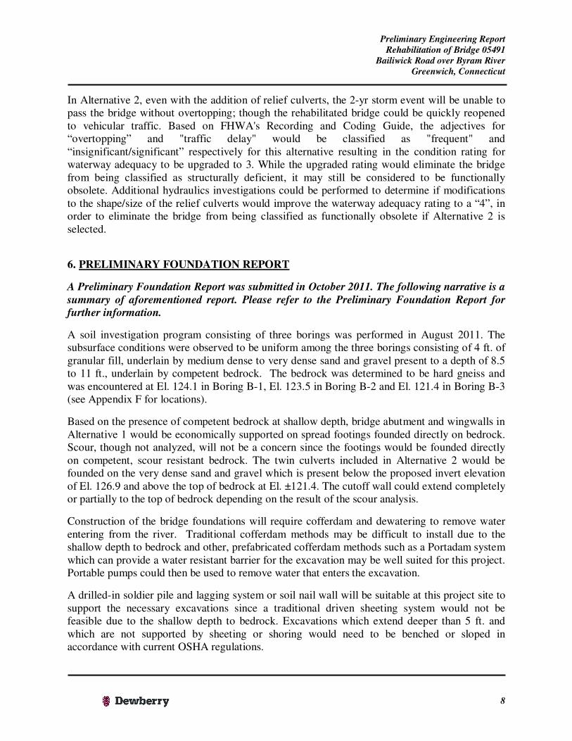
6. PRELIMINARY FOUNDATION REPORT
A Preliminary Foundation Report was submitted in October 2011. The following narrative is a
summary of aforementioned report. Please refer to the Preliminary Foundation Report for
further information.
A soil investigation program consisting of three borings was performed in August 2011. The
subsurface conditions were observed to be uniform among the three borings consisting of 4 ft. of
granular fill, underlain by medium dense to very dense sand and gravel present to a depth of 8.5
to 11 ft., underlain by competent bedrock. The bedrock was determined to be hard gneiss and
was encountered at El. 124.1 in Boring B-1, El. 123.5 in Boring B-2 and El. 121.4 in Boring B-3
(see Appendix F for locations).
Based on the presence of competent bedrock at shallow depth, bridge abutment and wingwalls in
Alternative 1 would be economically supported on spread footings founded directly on bedrock.
Scour, though not analyzed, will not be a concern since the footings would be founded directly
on competent, scour resistant bedrock. The twin culverts included in Alternative 2 would be
founded on the very dense sand and gravel which is present below the proposed invert elevation
of El. 126.9 and above the top of bedrock at El. ±121.4. The cutoff wall could extend completely
or partially to the top of bedrock depending on the result of the scour analysis.
Construction of the bridge foundations will require cofferdam and dewatering to remove water
entering from the river. Traditional cofferdam methods may be difficult to install due to the
shallow depth to bedrock and other, prefabricated cofferdam methods such as a Portadam system
which can provide a water resistant barrier for the excavation may be well suited for this project.
Portable pumps could then be used to remove water that enters the excavation.
A drilled-in soldier pile and lagging system or soil nail wall will be suitable at this project site to
support the necessary excavations since a traditional driven sheeting system would not be
feasible due to the shallow depth to bedrock. Excavations which extend deeper than 5 ft. and
which are not supported by sheeting or shoring would need to be benched or sloped in
accordance with current OSHA regulations.

Preliminary Engineering Report
Rehabilitation of Bridge 05491
Bailiwick Road over Byram River
Greenwich, Connecticut
9
7. ALTERNATE TRANSPORTATION MODES
The bridge provides the only official access to the community of approximately 200 residents.
There are no sidewalks on the bridge and the approach roads.
a. Pedestrian Path – Since the Bailiwick Road Bridge will be closed during the construction,
pedestrian traffic will be detoured via a private roadway belonging to Bailiwick Club as
depicted on Sheet No. 12 (Appendix C).
b. Bicycle Path – Currently no separate bicycle lanes are marked on any of the streets within the
project limits. Bicycle traffic using the corridor will be directed to use the aforementioned
pedestrian detour during the bridge construction.
8. RIGHTS OF WAY
The existing right of way (ROW) limits are approximately 25’ on each side of the Bailiwick
Road centerline (i.e. baseline). The land adjacent to the street lines along Bailiwick Road is
owned by the private owners. The land on the east side of Riversville Road is owned by private
owners. The land between Riversville Road and Byram River is owned by the Town.
The improvements proposed in Alternative 1 are within the existing street lines (ROW limits).
The channelization for relief culverts proposed in Alternative 2 would require permanent
easements and/or takes.
The approach roadway west of the bridge will be used for staging the construction operations.
Temporary easements from the private property owners will be necessary for the contractor to
access the bridge during the construction.
9. NOISE/AIR IMPACTS AND DESIGN FEATURES
No significant change in the vehicular traffic volume is anticipated after completion of this
project. There will be a temporary increase in the noise levels during construction.
10. DRAINAGE AND PERMITTING
The proposed roadway cross section will remain largely unchanged; therefore the quantity of
storm water draining to Byram River will not change because of this project. Based on this
assumption, a gutter flow analysis and pipe sizing analysis will not be performed.
a. Preliminary Drainage Issues – There is no existing storm sewer system on Bailiwick Road
within the project limits. The bituminous leak-off, located at Sta. 104+50 on the right side
(refer to Photo 7, Appendix A), carries the storm water from road surface to Byram River. In
order to improve roadway drainage, granite curb will be installed on both sides from Sta.
104+00 all the way to the project limits. Catch basins, installed on the west approach

Preliminary Engineering Report
Rehabilitation of Bridge 05491
Bailiwick Road over Byram River
Greenwich, Connecticut
10
roadway, will carry the storm water runoff to Byram River through 18” reinforced concrete
pipes and a manhole.
b. Water resource impacts – No impacts are anticipated.
c. Sedimentation and Erosion Control Measures – A silt fence will be provided along the toes
of slopes and the catch basin inlets will be protected by hay bales during construction.
d. Permit Involvement – Not Applicable
11. UTILITIES
Overhead utilities (telephone, cable and electric) present on the approach roadways will need to
be temporarily relocated during construction. While there are no current utility crossings under
the bridge, Alternative 1 provides an opportunity for future utilities to be carried by the bridge.
The channelization proposed in Alternative 2 will require the relocation of an exposed water
currently crossing Byram River upstream of the bridge. Test pits will be necessary to ascertain its
exact location in order to avoid impacts during the construction.
12. LANDSCAPING
Invasive vegetation if present within project limits will be removed and a modest landscaping
design plan will be developed to show proposed planting to address the areas of disturbance due
to construction.
13. CONSTRUCTION COST ESTIMATE
A summary of the cost estimates for the three alternatives described Section 4 assuming 35% for
incidentals and contingencies is shown below and attached as Appendix D.
Alternative Estimated Construction Cost (2011)
1 $ 1,880,000.00
2 $ 1,830,000.00
3 $ 1,360,000.00
14. SUMMARY AND CONCLUSIONS
Even though the bridge replacement alternative is estimated to be slightly more expensive,
improvement in hydraulic opening and minimizing potential overtopping during the lower
frequency storm events, a bridge structure not encroaching into the channel aiding the permitting
Preliminary Engineering Report
Rehabilitation of Bridge 05491
Bailiwick Road over Byram River
Greenwich, Connecticut
11
approval process and a new stronger bridge with a rigid concrete pavement that will not washout
and ensure that the bridge and the roadway can be quickly reopened to vehicular traffic
subsequent to storm events are some of the main benefits with this alternative. Other benefits
with this alternative include a new bridge with a service life of 50-75 years, maintenance free
nature of weathering steel beams and the feasibility of installing conduits for future utility
crossings.
For nearly the same cost as Alternative 1, the bridge rehabilitation alternative will provide for a
somewhat lesser hydraulics improvement; however a rehabilitated bridge with a service life of
30-40 years, the presence of a rigid reinforced concrete pavement and a spandrel wall positively
attached to the arch will ensure that the bridge can be quickly reopened to vehicular traffic
subsequent to overtopping events. The Town will be required to maintain an additional bridge
comprising of the two relief culverts.
While Alternative 3 costs the least amongst the three alternatives, no hydraulics benefits are
gained by lowering the west approach roadway. This alternative will also result in poor sight
distances at the west approach roadway. However, a rehabilitated bridge with a service life of
30-40 years, the presence of a rigid reinforced concrete pavement and a spandrel wall positively
attached to the arch will ensure that the bridge can be quickly reopened to vehicular traffic
subsequent to overtopping events.
Based on the benefits, cost estimate and duration of construction, we recommend the selection of
Alternative 1 with the construction of a new bridge. It is also recommended that the Town
investigate the feasibility of further improving the hydraulics by conducting a downstream
impact analysis.

Structure Type Study
Rehabilitation of Bridge 05491
Bailiwick Road over Byram River
Greenwich, Connecticut
Appendix A
Photos

59 Elm Street, Suite 101
New Haven, CT 06510
PRELIMINARY ENGINEERING REPORT
BRIDGE NO. 05491,BAILIWICK ROAD OVER BYRAM RIVER
GREENWICH, CT
Photo Sheet
1 of 2
Photo 1: Bridge from West Approach Photo 2: South elevation of bridge.
Photo 3: Bridge from east approach. Photo 4: West approach.

59 Elm Street, Suite 101
New Haven, CT 06510
PRELIMINARY ENGINEERING REPORT
BRIDGE NO. 05491,BAILIWICK ROAD OVER BYRAM RIVER
GREENWICH, CT
Photo Sheet
2 of 2
Photo 5: Intersection of Bailiwick Road and Riversville Photo 6: West Approach of Bridge. Note Posted Speed
Road, looking North. Limit
Photo 7: Existing Leak-off located at SW corner

Structure Type Study
Rehabilitation of Bridge 05491
Bailiwick Road over Byram River
Greenwich, Connecticut
Appendix B
Design Elements
Tables

DESIGN ELEMENTS TABLE – Alternative 1 (Bridge Replacement)
Design Element:
Design Standards Existing Proposed Design
English Units English Units English Units
Design Speed
Travel Lane Width
Approach Road
Bridge
Shoulder Width (Eastbound)
Approach Road
Bridge
Shoulder Width (Westbound)
Approach Road
Bridge
Cross Slope
Sidewalk Width
Stopping Sight Distance
Minimum Radius of curvature
Superelevation (e Max)
Maximum Grade
Minimum Grade
Vertical Curvature (K value)
Crest
Sag
20-25 mph
10-11 ft.
2-4 ft.
2-4 ft.
1.5% -2.0%
5 ft.
200 ft.
230 ft.
4.0%
10.0%
0.5%
19
37
25 mph(1)
11 ft.
11 ft.
0 ft.(2)
4 ft.
0 ft.(2)
4 ft.
2.0%
0 ft.(2)
500 ft.
950 ft.
2.0%
2.0%
0.8%
38
34
30 mph (1)
11 ft.
11 ft.
0 ft.(2)*
3 ft.
0 ft.(2)*
3 ft.
2.0%
0 ft.(2)*
447 ft.
950 ft.
2.0%
2.0%
1.0%
60
73
Legend (1) The posted speed limit is 25 mph on Bailiwick Road.
(2) Currently not present within project limits.
* Design exception will be sought for these criteria. A design exception will be sought as this is a bridge
rehabilitation project and major approach roadway rework is not warranted. Existing substandard conditions will
be improved to the extent reasonable and feasible without involving right of way impacts.

DESIGN ELEMENTS TABLE – Alternative 2 (Bridge Rehabilitation)
Design Element:
Design Standards Existing Proposed Design
English Units English Units English Units
Design Speed
Travel Lane Width
Approach Road
Bridge
Shoulder Width (Eastbound)
Approach Road
Bridge
Shoulder Width (Westbound)
Approach Road
Bridge
Cross Slope
Sidewalk Width
Stopping Sight Distance
Minimum Radius of curvature
Superelevation (e Max)
Maximum Grade
Minimum Grade
Vertical Curvature (K value)
Crest
Sag
20-25 mph
10-11 ft.
2-4 ft.
2-4 ft.
1.5% -2.0%
5 ft.
200 ft.
230 ft.
4.0%
10.0%
0.5%
19
37
25 mph(1)
11 ft.
11 ft.
0 ft.(2)
4 ft.
0 ft. (2)
4 ft.
2.0%
0 ft.(2)
500 ft.
950 ft.
2.0%
2.0%
0.8%
38
34
30 mph (1)
11 ft.
11 ft.
0 ft. (2)*
3 ft.
0 ft. (2)*
3 ft. (min.)
2.0%
0 ft.(2)*
217 ft.
950 ft.
2.0%
2.0%
0.5%
22
41
Legend (1) The posted speed limit is 25 mph on Bailiwick Road.
(2) Currently not present within project limits.
* Design exception will be sought for these criteria. A design exception will be sought as this is a bridge
rehabilitation project and major approach roadway rework is not warranted. Existing substandard conditions will
be improved to the extent reasonable and feasible without involving right of way impacts.

Structure Type Study
Rehabilitation of Bridge 05491
Bailiwick Road over Byram River
Greenwich, Connecticut
Appendix C
Plans and Profiles

- -
-
-
-
- -
- - -
- - - -
- - -
- - -
- - - -
REHABILITATION OF BRIDGE
NO. 05491 BAILIWICK ROAD
OVER BYRAM RIVER
GREENWICH 56-299R. BHAVE
G. JACOBS
TYPICAL SECTIONS
25.0’ 25.0’
} BAILIWICK RD
2%2%
FROM STA. 102+60.00 TO STA. 104+00.00
25.0’ 25.0’
} BAILIWICK RD
2%2%
FROM STA. 104+00.00 TO STA. 104+90.00
4% 4%
FROM STA. 104+90.00 TO STA. 105+35.00
FROM STA. 105+85.00 TO STA. 106+11.00
} BAILIWICK RD
2:1
4% 4%
2:1
2%2%
VARIES (0’-3’)VARIES (0’-3’)
GRANITE CURB (TYP.)
SL SL
SLSL
5.5’ 5.5’
5.5’ 5.5’
6:16:1
3’.0 11.0’ 11.0’ 3.0’
11.0’ 11.0’
11.0’ 11.0’
BAILIWICK RD - ALTERNATE 1
BAILIWICK RD- ALTERNATE 1
BAILIWICK RD- ALTERNATE 1
25.0’ 25.0’
} BAILIWICK RD
2%2%
FROM STA. 102+60.00 TO STA. 104+00.00
25.0’ 25.0’
} BAILIWICK RD
2%2%
FROM STA. 104+00.00 TO STA. 104+90.00
4% 4%
FROM STA. 104+90.00 TO STA. 105+48.00
FROM STA. 105+80.00 TO STA. 106+11.00
} BAILIWICK RD
2:1
4% 4%
2:1
2%2%
VARIES (0’-3’)
GRANITE CURB (TYP.)
SL SL
SLSL
5.5’ 5.5’
5.5’ 5.5’
6:16:1
11.0’ 11.0’ 3.0’
11.0’ 11.0’
11.0’ 11.0’
BAILIWICK RD - ALTERNATE 2
BAILIWICK RD- ALTERNATE 2
BAILIWICK RD- ALTERNATE 2
VARIES (0’-3.6’)
VARIES
1
PRELIMINARY ENGINEERING REPORT
DESIGNER/DRAFTER:
CHECKED BY:
PROJECT TITLE: TOWN:
DRAWING TITLE:
PROJECT NO.
DRAWING NO.
SHEET NO.
Filename:SHEET NO.REVISION DESCRIPTIONDATEREV.
DEPARTMENT OF PUBLIC WORKS
TOWN OF GREENWICH
NOT TO SCALE
11/3/2011
BLOCK:
SIGNATURE/
DATE: APPROVED BY:
Dewberry-Goodkind, Inc.
...\HW_MSH_056_0299_TYP-1.dgnPlotted Date:

3 in.3 in.
3 in.
5 in.
5 in.
5 in.
5 in.
15 in.
15 in.
16 in.
8 in.
8 in.8 in.
8 in.
8 in.
8 in.
8 in.
8 in.
TW 8 in.
8 in.
4 in.
4 in.
4 in.
4 in.4 in.
4 in.12 in.
3 in.
10 in.
10 in.
10 in.
10 in.
10 in.
10 in.
36 in.
2 in.
12 in. 12 in.
12 in.12 in.
14 in.
6 in.
18 in.
6 in.
9 in.
TW 12/15in.
TW 2/3 in.
TW 3/5 in.
TW 4/5 in.
HIDDEN DRIVE
SLOW
SIGN
ELEC
TELE
UG UTIL
TELE
UG UTIL
BAILIWICK ROAD
SCHALLER
CAROLLATA & HOWARD
N/F
15 BAILIWICK ROAD
THOMAS
HARRY III & MERI
N/F
7 BAILWICK ROAD
JOHNSON
TODD & NICOLE
N/F
8 BAILIWICK ROAD
140
140
140
150
150
- -
-
-
-
- -
- - -
- - - -
- - -
- - -
- - - -
REHABILITATION OF BRIDGE
NO. 05491 BAILIWICK ROAD
OVER BYRAM RIVER
GREENWICH
ROADWAY PLANALTERNATE 1
56-299R. BHAVE
G. JACOBS
11’
BEGIN STATE PROJECT NO. 056-0299
BAILIWICK ROAD
CO
NN
EC
TIC
UT
CO
OR
DIN
AT
E
GRID
SAW CUT EXISTING PVMT.
LIMIT OF FULL DEPTH PVMT. RECONST.
E = 747957.13
N = 579000.46
STA. 102+60
11’
BAILIWICK ROAD
= 15°29’07.2"
= 95.17’
= 186.30’
= 370’
= 28°50’54.3"
D
T
L
R
D
T
L
R
= 4°00’24.1"
= 111.84’
= 223.22’
= 1430’
= 8°56’37.1"
1
2
} CURVE DATA 1
} CURVE DATA 2
2
EXIST. R-O-W
EXIST. R-O-W
PRELIMINARY ENGINEERING REPORT
DESIGNER/DRAFTER:
CHECKED BY:
PROJECT TITLE: TOWN:
DRAWING TITLE:
PROJECT NO.
DRAWING NO.
SHEET NO.
Filename:SHEET NO.REVISION DESCRIPTIONDATEREV.
DEPARTMENT OF PUBLIC WORKS
TOWN OF GREENWICH
SCALE 1"=20’
20 400
SCALE IN FEET
11/3/2011
BLOCK:
SIGNATURE/
DATE: APPROVED BY:
Dewberry-Goodkind, Inc.
...\HW_MSH_056_0299_PLN-1-ALT 1.dgnPlotted Date:
MA
TC
H
LIN
E S
EE S
HE
ET
NO. 4
100+00
101+00
102+00
103+00
E 747703.8
7N
579042.2
5100+
00.0
0P
C
E 747887.2
9
N 579024.0
0
101+
86.3
0
PR
C

- -
-
-
-
- -
- - -
- - - -
- - -
- - -
- - - - GREENWICH
ROADWAY PROFILEALTERNATE 1
REHABILITATION OF BRIDGE
NO. 05491 BAILIWICK ROAD
OVER BRYAM RIVER
R. BHAVE
G. JACOBS
56-299
103+00102+00101+00100+00
120
130
140
150
120
130
140
150
BEGIN STATE PROJECT NO. 056-0299
LIMIT OF FULL DEPTH PVMT. RECONST.MEET EXISTING PVMT.E = 747957.13N = 579000.46STA. 102+60
BAILIWICK ROAD
DIRECTION OF TRAVEL - TWO WAY
EXISTING GROUND ALONG }
FULL DEPTH PVMT. RECONST.
{
EX.
DRIV
EW
AY (N
OR
TH)
{
EX.
DRIV
EW
AY (N
OR
TH)
ALONG }
PROPOSED GRADE
3
FULL DEPTH H.M.A.
PRELIMINARY ENGINEERING REPORT
DESIGNER/DRAFTER:
CHECKED BY:
PROJECT TITLE: TOWN:
DRAWING TITLE:
PROJECT NO.
DRAWING NO.
SHEET NO.
Filename:SHEET NO.REVISION DESCRIPTIONDATEREV.
DEPARTMENT OF PUBLIC WORKS
TOWN OF GREENWICH
OF WORK WHICH WILL BE REQUIRED.
THE CONDITIONS OF ACTUAL QUANTITIES
IN NO WAY WARRANTED TO INDICATE
INVESTIGATIONS BY THE STATE AND IS
SHEETS IS BASED ON LIMITED
QUANTITIES OF WORK, SHOWN ON THESE
THE INFORMATION, INCLUDING ESTIMATED
11/3/2011
BLOCK:
SIGNATURE/
DATE: APPROVED BY:
Dewberry-Goodkind, Inc.
HORIZ. SCALE IN FEET
VERT. SCALE IN FEET
0 2 4
0 20 40
...\HW_MSH_056_0299_PRO-1-ALT 1.dgnPlotted Date:
MA
TC
H
LIN
E S
EE S
HE
ET
NO. 5
K=73.07
PV
C
ST
A.1
02+
60.0
0
EL.=
134.8
4
L.V.C.=210.00
S.S.D.=446.47

4 in.
4 in. 3 in.
8 in.8 in.
1 in.
12 in.
16 in.
24 in.
18 in.
4 in.
8 in.
2 in.
2 in.
20 in.
TW 10/16 in.
Q 8 in.
8 in.
8 in.
Q 8 in.
TW 8 in.
8 in.
6 in.
8 in.
4 in.
4 in.
8 in.
3 in.
3 in.
10 in.
24 in.
36 in.
2 in.
2 in.
2 in.2 in.
2 in.
2 in.
12 in.
4 in.
3 in.
1 in.
32 in.
6x1 in.
TW 5 in.
8 in.
18 in.
36 in.
30 in.
TW 2 in.
TW 1/3 in.
TW 1 in.
TW 14 in.
TW 5/6 in.
TR 6/2/2 in.
TR 3 in.
80134
CL&P
8134A
CL&P
69239
CL&P
69240
CL&P
WF 41
WF 42
WF 43
WF 44
WF 45
WF 46
WF 47
WF 30
WF 31
WF 32
WF 33
WF 34
WF 35
WF 26
WF 25
WF 24
WF 23
WF 22
WF 21
WF 20
WF 5
WF 1
WF 2
WF 3
WF 4
WF 6
WF 9
WF 10
NO OUTLET
SIGN
STOP
SIGN
STREET
SIGN
NO PARK
SIGN
25MPH
SIGN
AT&T
UGUF
CATV
UGUF
CL&P
UGUF
CL&P
UGUF
CATV
UGUF
CATV
UGUF
BIT. L.O.
BIT. L.O.
JPG-3 (I. PIN)
JPG-1 (I. PIN)
E 7
48400
N 578800
BAILIWICK ROAD
RIV
ER
VIL
LE R
OA
D
No. 05491
BRIDGE
AQUARION WATER CO.EXPOSED WATER MAIN
130
130
130
130
130
130
130
130
130
130
140
140
140
140
150
150
- -
-
-
-
- -
- - -
- - - -
- - -
- - -
- - - -
REHABILITATION OF BRIDGE
NO. 05491 BAILIWICK ROAD
OVER BYRAM RIVER
GREENWICH
ROADWAY PLANALTERNATE 1
56-299R. BHAVE
G. JACOBS
11’
11’
CO
NN
EC
TIC
UT
CO
OR
DIN
AT
E
GRID
BAILIWICK ROAD
RIV
ERS
VIL
LE
RO
AD
GRANITE CURB
GRANITE CURB
END STATE PROJECT NO. 056-0299
14’
14’
BRIDGE NO. 05491
LIMIT OF FULL DEPTH PVMT RECONST.
E = 748369.90
N = 578921.10
STA. 106+81.05
18" RCP
18" RCP
18" R
CP
BYRA
M
RIV
ER
12.0’
12.0’
12.5’
12.5’
INV.=129.31
TF=133.21
STA. 104+05
"C" CB
INV.=129.42
TF=133.21
STA. 104+05
"C" CB
INV.=128.67
STA. 105+40, 23’ RTINV.=128.98
TC=133.00
STA. 104+75, 23’ RT
4’ DIA. MH
14’
RIV
ER
VIL
LE R
OA
D
BYR
AM
RIV
ER
20’ R
40’ R
14’
+11
+38
SAW CUT
EXISTI
NG PVMT.
PVMT. RECOST.
LIMIT O
F FULL
DEP
TH
+45
SAW CUT
EXISTI
NG PVMT.
PVMT. RECOST.
LIMIT O
F FULL
DEP
TH
+70
+00
+90
SHLD. TAPER(30:1) BOTH EDGES
SIGN
NO OUTLET
SIGN
STOP
SIGN
25 MPH2
D
T
L
R
= 4°00’24.1"
= 111.84’
= 223.22’
= 1430’
= 8°56’37.1"
} CURVE DATA 2
3
D
T
L
R
} CURVE DATA 3
= 6°01’52.1"
= 56.30’
= 112.46’
= 950’
= 6°46’58.3"
4
EXIST. R-O-W
EXIST. R-O-W
RAIL (TYP.)
BOX BEAM
PRELIMINARY ENGINEERING REPORT
DESIGNER/DRAFTER:
CHECKED BY:
PROJECT TITLE: TOWN:
DRAWING TITLE:
PROJECT NO.
DRAWING NO.
SHEET NO.
Filename:SHEET NO.REVISION DESCRIPTIONDATEREV.
DEPARTMENT OF PUBLIC WORKS
TOWN OF GREENWICH
SCALE 1"=20’
20 400
SCALE IN FEET
11/3/2011
BLOCK:
SIGNATURE/
DATE: APPROVED BY:
Dewberry-Goodkind, Inc.
...\HW_MSH_056_0299_PLN-2-ALT 1.dgnPlotted Date:
STA. 105+30.5
BEGIN BRIDGE
STA. 105+89.6
END BRIDGEMA
TC
H
LIN
E S
EE S
HE
ET
NO. 2
E 748102.0
3
N 578963.9
1
104+
09.5
1
PT
E 748342.8
6
N
578923.1
7
106+
53.9
3
PT
E 748369.9
0
N
578921.1
0
106+
81.0
5
PO
E
N78° 50’18.6"E
S 24°
17’5
2.8
7" E
200+
00
201+
00
202+
00
E 74
8312.78
N 57
9018.72
200+
00.00
POB
E 74
8395.07
N 57
8836.43
202+
00.00
POE
E = 748356.38
N = 578922.14
STA. 201+05.96 RIVERVILLE ROAD
STA. 106+67.49 BAILIWICK ROAD =
EQ:
104
105
106
E 748231.4
9
N 578938.3
7
105+
41.4
6
PC

- -
-
-
-
- -
- - -
- - - -
- - -
- - -
- - - - GREENWICH
ROADWAY PROFILEALTERNATE 1
REHABILITATION OF BRIDGE
NO. 05491 BAILIWICK ROAD
OVER BRYAM RIVER
R. BHAVE
G. JACOBS
56-299
107+00106+00105+00104+00
120
130
140
150
120
130
140
150
BAILIWICK ROAD
DIRECTION OF TRAVEL - TWO WAY
FULL DEPTH PVMT. RECONST.
END STATE PROJECT NO. 056-0299
LIMIT OF FULL DEPTH PVMT RECONST.E = 748369.90N = 578921.10STA. 106+81.05
{
EX.
DRIV
EW
AY (S
OU
TH)
EXISTING GROUND ALONG }
18" RCP18" RCP
INV.=129.31
TF=133.21
STA. 104+05
"C" CB
INV.=128.98
TC=133.00
STA. 104+75, 23’ RT
4’ DIA. MH
INV.=128.67
STA. 105+40, 23’ RT
BRIDGE NO. 05491
FULL DEPTH PVMT. RECONST.
ALONG }
PROPOSED GRADE
5
FULL DEPTH H.M.A.
ON TOP OF 8" CONCRETE SLAB
2" BITUMINOUS CONCRETE OVERLAYFULL DEPTH H.M.A.
PRELIMINARY ENGINEERING REPORT
DESIGNER/DRAFTER:
CHECKED BY:
PROJECT TITLE: TOWN:
DRAWING TITLE:
PROJECT NO.
DRAWING NO.
SHEET NO.
Filename:SHEET NO.REVISION DESCRIPTIONDATEREV.
DEPARTMENT OF PUBLIC WORKS
TOWN OF GREENWICH
OF WORK WHICH WILL BE REQUIRED.
THE CONDITIONS OF ACTUAL QUANTITIES
IN NO WAY WARRANTED TO INDICATE
INVESTIGATIONS BY THE STATE AND IS
SHEETS IS BASED ON LIMITED
QUANTITIES OF WORK, SHOWN ON THESE
THE INFORMATION, INCLUDING ESTIMATED
11/3/2011
BLOCK:
SIGNATURE/
DATE: APPROVED BY:
Dewberry-Goodkind, Inc.
HORIZ. SCALE IN FEET
VERT. SCALE IN FEET
0 2 4
0 20 40
...\HW_MSH_056_0299_PRO-2-ALT 1.dgnPlotted Date:
+30.5
+89.6
{
RIV
ER
SVILLE
RO
AD
MA
TC
H
LIN
E S
EE S
HE
ET
NO. 3
K=73.07
PVI S
TA.1
03+
65.0
0
EL.=
132.8
8
L.P.
ST
A.1
03+
95.9
5
EL.=
133.5
7
PV
RC
ST
A.1
04+
70.0
0
EL.=
133.9
5
H.P.
ST
A.1
05+
30.3
7
EL.=
134.2
5
PVI S
TA.1
05+
60.0
0
EL.=
134.8
6
PV
T S
TA.1
06+
50.0
0
EL.=
133.0
5
PVI S
TA.1
06+
67.4
9
EL.=
132.7
0
PVI S
TA.1
06+
81.0
5
EL.=
132.4
3
S=-2.00%
S=-2.01%
L.V.C.=210.00
S.S.D.=446.47
L.V.C.=180.00
S.S.D.=447.19
K=59.58

3 in.3 in.
3 in.
5 in.
5 in.
5 in.
5 in.
15 in.
15 in.
16 in.
8 in.
8 in.8 in.
8 in.
8 in.
8 in.
8 in.
8 in.
TW 8 in.
8 in.
4 in.
4 in.
4 in.
4 in.4 in.
4 in.12 in.
3 in.
10 in.
10 in.
10 in.
10 in.
10 in.
10 in.
36 in.
2 in.
12 in. 12 in.
12 in.12 in.
14 in.
6 in.
18 in.
6 in.
9 in.
TW 12/15in.
TW 2/3 in.
TW 3/5 in.
TW 4/5 in.
HIDDEN DRIVE
SLOW
SIGN
ELEC
TELE
UG UTIL
TELE
UG UTIL
BAILIWICK ROAD
SCHALLER
CAROLLATA & HOWARD
N/F
15 BAILIWICK ROAD
THOMAS
HARRY III & MERI
N/F
7 BAILWICK ROAD
JOHNSON
TODD & NICOLE
N/F
8 BAILIWICK ROAD
140
140
140
150
150
- -
-
-
-
- -
- - -
- - - -
- - -
- - -
- - - -
REHABILITATION OF BRIDGE
NO. 05491 BAILIWICK ROAD
OVER BYRAM RIVER
GREENWICH
ROADWAY PLANALTERNATE 2
56-299R. BHAVE
G. JACOBS
} BAILIWICK ROAD
11’
BEGIN STATE PROJECT NO. 056-0299
BAILIWICK ROAD
CO
NN
EC
TIC
UT
CO
OR
DIN
AT
E
GRID
SAW CUT EXISTING PVMT.
LIMIT OF FULL DEPTH PVMT. RECONST.
E = 747957.13
N = 579000.46
STA. 102+60
11’
= 15°29’07.2"
= 95.17’
= 186.30’
= 370’
= 28°50’54.3"
D
T
L
R
} CURVE DATA 1
D
T
L
R
= 4°00’24.1"
= 111.84’
= 223.22’
= 1430’
= 8°56’37.1"
} CURVE DATA 2
2
1BAILIWICK ROAD
6
EXIST. R-O-W
EXIST. R-O-W
PRELIMINARY ENGINEERING REPORT
DESIGNER/DRAFTER:
CHECKED BY:
PROJECT TITLE: TOWN:
DRAWING TITLE:
PROJECT NO.
DRAWING NO.
SHEET NO.
Filename:SHEET NO.REVISION DESCRIPTIONDATEREV.
DEPARTMENT OF PUBLIC WORKS
TOWN OF GREENWICH
SCALE 1"=20’
20 400
SCALE IN FEET
11/3/2011
BLOCK:
SIGNATURE/
DATE: APPROVED BY:
Dewberry-Goodkind, Inc.
...\HW_MSH_056_0299_PLN-1-ALT 2.dgnPlotted Date:
MA
TC
H
LIN
E S
EE S
HE
ET
NO. 8
100+00
101+00
102+00
103+00
E 747703.8
7N
579042.2
5100+
00.0
0P
C
E 747887.2
9
N 579024.0
0
101+
86.3
0
PR
C

- -
-
-
-
- -
- - -
- - - -
- - -
- - -
- - - - GREENWICH
ROADWAY PROFILEALTERNATE 2
REHABILITATION OF BRIDGE
NO. 05491 BAILIWICK ROAD
OVER BRYAM RIVER
R. BHAVE
G. JACOBS
56-299
103+00102+00101+00100+00
120
130
140
150
120
130
140
150
BEGIN STATE PROJECT NO. 056-0299
LIMIT OF FULL DEPTH PVMT. RECONST.MEET EXISTING PVMT.E = 747957.13N = 579000.46STA. 102+60
BAILIWICK ROAD
DIRECTION OF TRAVEL - TWO WAY
EXISTING GROUND ALONG }
FULL DEPTH PVMT. RECONST.
{
EX.
DRIV
EW
AY (N
OR
TH)
{
EX.
DRIV
EW
AY (N
OR
TH)
ALONG }
PROPOSED GRADE
7
FULL DEPTH H.M.A.
PRELIMINARY ENGINEERING REPORT
DESIGNER/DRAFTER:
CHECKED BY:
PROJECT TITLE: TOWN:
DRAWING TITLE:
PROJECT NO.
DRAWING NO.
SHEET NO.
Filename:SHEET NO.REVISION DESCRIPTIONDATEREV.
DEPARTMENT OF PUBLIC WORKS
TOWN OF GREENWICH
OF WORK WHICH WILL BE REQUIRED.
THE CONDITIONS OF ACTUAL QUANTITIES
IN NO WAY WARRANTED TO INDICATE
INVESTIGATIONS BY THE STATE AND IS
SHEETS IS BASED ON LIMITED
QUANTITIES OF WORK, SHOWN ON THESE
THE INFORMATION, INCLUDING ESTIMATED
11/3/2011
BLOCK:
SIGNATURE/
DATE: APPROVED BY:
Dewberry-Goodkind, Inc.
HORIZ. SCALE IN FEET
VERT. SCALE IN FEET
0 2 4
0 20 40
...\HW_MSH_056_0299_PRO-1-ALT 2.dgnPlotted Date:
MA
TC
H
LIN
E S
EE S
HE
ET
NO. 9
PVI S
TA.1
02+
60.0
0
EL.=
134.8
4
PV
C
ST
A.1
02+
80.0
0
EL.=
134.4
3
S=-2.05%
L.V.C.=180.00
S.S.D.=534.42
K=70.47

4 in.
4 in. 3 in.
8 in.8 in.
1 in.
12 in.
16 in.
24 in.
18 in.
4 in.
8 in.
2 in.
2 in.
20 in.
TW 10/16 in.
Q 8 in.
8 in.
8 in.
Q 8 in.
TW 8 in.
8 in.
6 in.
8 in.
4 in.
4 in.
8 in.
3 in.
3 in.
10 in.
24 in.
36 in.
2 in.
2 in.
2 in.2 in.
2 in.
2 in.
12 in.
4 in.
3 in.
1 in.
32 in.
6x1 in.
TW 5 in.
8 in.
18 in.
36 in.
30 in.
TW 2 in.
TW 1/3 in.
TW 1 in.
TW 14 in.
TW 5/6 in.
TR 6/2/2 in.
TR 3 in.
80134
CL&P
8134A
CL&P
69239
CL&P
69240
CL&P
WF 41
WF 42
WF 43
WF 44
WF 45
WF 46
WF 47
WF 30
WF 31
WF 32
WF 33
WF 34
WF 35
WF 26
WF 25
WF 24
WF 23
WF 22
WF 21
WF 20
WF 5
WF 1
WF 2
WF 3
WF 4
WF 6
WF 9
WF 10
NO OUTLET
SIGN
STOP
SIGN
STREET
SIGN
NO PARK
SIGN
25MPH
SIGN
AT&T
UGUF
CATV
UGUF
CL&P
UGUF
CL&P
UGUF
CATV
UGUF
CATV
UGUF
BIT. L.O.
BIT. L.O.
JPG-3 (I. PIN)
JPG-1 (I. PIN)
E 7
48400
N 578800
BAILIWICK ROAD
RIV
ER
VIL
LE R
OA
D
No. 05491
BRIDGE
AQUARION WATER CO.EXPOSED WATER MAIN
130
130
130
130
130
130
130
130
130
130
140
140
140
140
150
150
- -
-
-
-
- -
- - -
- - - -
- - -
- - -
- - - -
REHABILITATION OF BRIDGE
NO. 05491 BAILIWICK ROAD
OVER BYRAM RIVER
GREENWICH
ROADWAY PLANALTERNATE 2
56-299R. BHAVE
G. JACOBS
11’
11’
CO
NN
EC
TIC
UT
CO
OR
DIN
AT
E
GRID
BAILIWICK ROAD
RIV
ERS
VIL
LE
RO
AD
GRANITE CURB
GRANITE CURB
END STATE PROJECT NO. 056-0299
14’
BRIDGE NO. 05491
LIMIT OF FULL DEPTH PVMT RECONST.
E = 748369.90
N = 578921.10
STA. 106+81.05
18" RCP
18" R
CP
BYRA
M
RIV
ER
12.0’
12.0’
12.5’
12.5’
INV.=128.05
TF=132.72
STA. 104+74
"C" CB
INV.=128.19
TF=132.72
STA. 104+74
"C" CB
RIV
ER
VIL
LE R
OA
D
BYR
AM
RIV
ER
20’ R
40’ R
14’
+09
+38
SAW CUT
EXISTI
NG PVMT.
PVMT. RECOST.
LIMIT O
F FULL
DEP
TH
+45
SAW CUT
EXISTI
NG PVMT.
PVMT. RECOST.
LIMIT O
F FULL
DEP
TH
+70
FL 127.4
FL 126.7
FL 126.9
FL 127.1
FILL BOTTOM 1’
TWO- 4’ X 9’ BOX CULVERTS
RC
P
18"
SIGN
STOP
SIGN
25 MPH
SIGN
NO OUTLET
FL 126.9
+95
104
INV. OUT=127.26
INV. IN=128.02
TC=130.60
STA. 104+75, 23’ RT
4’ DIA. MH
2
D
T
L
R
= 4°00’24.1"
= 111.84’
= 223.22’
= 1430’
= 8°56’37.1"
} CURVE DATA 2
D
T
L
R
= 6°01’52.1"
= 56.30’
= 112.46’
= 950’
= 6°46’58.3"
} CURVE DATA 3
3
14’-7"
14’-7"
+00
SHLD. TAPER
+90
BOTH EDGES
8
EXIST. R-O-W
EXIST. R-O-W
RAIL (TYP.)
BOX BEAM
PAVERS
CONCRETE BLOCK
PRELIMINARY ENGINEERING REPORT
DESIGNER/DRAFTER:
CHECKED BY:
PROJECT TITLE: TOWN:
DRAWING TITLE:
PROJECT NO.
DRAWING NO.
SHEET NO.
Filename:SHEET NO.REVISION DESCRIPTIONDATEREV.
DEPARTMENT OF PUBLIC WORKS
TOWN OF GREENWICH
SCALE 1"=20’
20 400
SCALE IN FEET
11/3/2011
BLOCK:
SIGNATURE/
DATE: APPROVED BY:
Dewberry-Goodkind, Inc.
...\HW_MSH_056_0299_PLN-2-ALT 2.dgnPlotted Date:
MA
TC
H
LIN
E S
EE S
HE
ET
NO. 6
E 748102.0
3
N 578963.9
1
104+
09.5
1
PT
E 748342.8
6
N
578923.1
7
106+
53.9
3
PT
E 748369.9
0
N
578921.1
0
106+
81.0
5
PO
E
N78° 50’18.6"E
S 24°
17’5
2.8
7" E
200+
00
201+
00
202+
00
E 74
8312.78
N 57
9018.72
200+
00.00
POB
E 74
8395.07
N 57
8836.43
202+
00.00
POE
E = 748356.38
N = 578922.14
STA. 201+05.96 RIVERVILLE ROAD
STA. 106+67.49 BAILIWICK ROAD =
EQ:
104
105
106
E 748231.4
9
N 578938.3
7
105+
41.4
6
PC
130

- -
-
-
-
- -
- - -
- - - -
- - -
- - -
- - - - GREENWICH
ROADWAY PROFILEALTERNATE 2
REHABILITATION OF BRIDGE
NO. 05491 BAILIWICK ROAD
OVER BRYAM RIVER
R. BHAVE
G. JACOBS
56-299
107+00106+00105+00104+00
120
130
140
150
120
130
140
150
BAILIWICK ROAD
DIRECTION OF TRAVEL - TWO WAY
FULL DEPTH PVMT. RECONST.
END STATE PROJECT NO. 056-0299
LIMIT OF FULL DEPTH PVMT RECONST.E = 748369.90N = 578921.10STA. 106+81.05
{
EX.
DRIV
EW
AY (S
OU
TH)
EXISTING GROUND ALONG }
18" RCP
INV.=128.05
TF=132.72
STA. 104+74
"C" CB
BRIDGE NO. 05491
FL=126.90
STA. 104+95, 23’ RT2-4’X9’ BOX CULVERTS
FL. 127.0
INV. OUT=127.26
INV. IN=128.02
TC=130.60
STA. 104+75, 23’ RT
4’ DIA. MH
FULL DEPTH PVMT. RECONST.+48
ALONG }
PROPOSED GRADE
9
FULL DEPTH H.M.A. FULL DEPTH H.M.A.
PRELIMINARY ENGINEERING REPORT
DESIGNER/DRAFTER:
CHECKED BY:
PROJECT TITLE: TOWN:
DRAWING TITLE:
PROJECT NO.
DRAWING NO.
SHEET NO.
Filename:SHEET NO.REVISION DESCRIPTIONDATEREV.
DEPARTMENT OF PUBLIC WORKS
TOWN OF GREENWICH
OF WORK WHICH WILL BE REQUIRED.
THE CONDITIONS OF ACTUAL QUANTITIES
IN NO WAY WARRANTED TO INDICATE
INVESTIGATIONS BY THE STATE AND IS
SHEETS IS BASED ON LIMITED
QUANTITIES OF WORK, SHOWN ON THESE
THE INFORMATION, INCLUDING ESTIMATED
11/3/2011
BLOCK:
SIGNATURE/
DATE: APPROVED BY:
Dewberry-Goodkind, Inc.
HORIZ. SCALE IN FEET
VERT. SCALE IN FEET
0 2 4
0 20 40
...\HW_MSH_056_0299_PRO-2-ALT 2.dgnPlotted Date:
{
RIV
ER
SVILLE
RO
AD
+09
8" CONCRETE PAVEMENT
MA
TC
H
LIN
E S
EE S
HE
ET
NO. 7
PVI S
TA.1
03+
70.0
0
EL.=
132.5
8
L.P.
ST
A.1
04+
24.5
8
EL.=
132.9
4
PV
CC
ST
A.1
04+
60.0
0
EL.=
133.0
3
PVI S
TA.1
04+
90.0
0
EL.=
133.1
8
PV
RC
ST
A.1
05+
20.0
0
EL.=
133.7
8
PVI S
TA.1
05+
60.0
0
EL.=
134.5
7
H.P.
ST
A.1
05+
62.6
0
EL.=
134.2
0
PV
T S
TA.1
06+
00.0
0
EL.=
133.8
7
PVI S
TA.1
06+
67.4
9
EL.=
132.7
0
PVI S
TA.1
06+
81.0
5
EL.=
132.4
3
S=-1.74%
S=-2.00%
L.V.C.=180.00
S.S.D.=534.42
K=70.47
L.V.C.=60.00
S.S.D.=217.15
K=40.65
L.V.C.=80.00
S.S.D.=330.42
K=21.53

10
- -
-
-
-
- -
- - -
- - - -
- - -
- - -
- - - - GREENWICH
ROADWAY PROFILEALTERNATE 3
REHABILITATION OF BRIDGE
NO. 05491 BAILIWICK ROAD
OVER BRYAM RIVER
R. BHAVE
G. JACOBS
56-299
103+00102+00101+00100+00
120
130
140
150
120
130
140
150
BEGIN STATE PROJECT NO. 056-0299
LIMIT OF FULL DEPTH PVMT. RECONST.MEET EXISTING PVMT.E = 747957.13N = 579000.46STA. 102+60
BAILIWICK ROAD
DIRECTION OF TRAVEL - TWO WAY
EXISTING GROUND ALONG }
FULL DEPTH PVMT. RECONST.
{
EX.
DRIV
EW
AY (N
OR
TH)
{
EX.
DRIV
EW
AY (N
OR
TH)
L.V.C.=140.00
S.S.D.=558.77
K=132.54
ALONG }
PROPOSED GRADE
PRELIMINARY ENGINEERING REPORT
DESIGNER/DRAFTER:
CHECKED BY:
PROJECT TITLE: TOWN:
DRAWING TITLE:
PROJECT NO.
DRAWING NO.
SHEET NO.
Filename:SHEET NO.REVISION DESCRIPTIONDATEREV.
DEPARTMENT OF PUBLIC WORKS
TOWN OF GREENWICH
OF WORK WHICH WILL BE REQUIRED.
THE CONDITIONS OF ACTUAL QUANTITIES
IN NO WAY WARRANTED TO INDICATE
INVESTIGATIONS BY THE STATE AND IS
SHEETS IS BASED ON LIMITED
QUANTITIES OF WORK, SHOWN ON THESE
THE INFORMATION, INCLUDING ESTIMATED
11/3/2011
BLOCK:
SIGNATURE/
DATE: APPROVED BY:
Dewberry-Goodkind, Inc.
HORIZ. SCALE IN FEET
VERT. SCALE IN FEET
0 2 4
0 20 40
...\HW_MSH_056_0299_PRO-1-ALT 3.dgnPlotted Date:
8" CONCRETE PAVEMNT
MA
TC
H
LIN
E S
EE S
HE
ET
NO. 11
PVI S
TA.1
02+
60.0
0
EL.=
134.8
4
PV
C
ST
A.1
03+
00.0
0
EL.=
134.0
6
S=-1.95%

11
- -
-
-
-
- -
- - -
- - - -
- - -
- - -
- - - - GREENWICH
ROADWAY PROFILEALTERNATE 3
REHABILITATION OF BRIDGE
NO. 05491 BAILIWICK ROAD
OVER BRYAM RIVER
R. BHAVE
G. JACOBS
56-299
107+00106+00105+00104+00
120
130
140
150
120
130
140
150
BAILIWICK ROAD
DIRECTION OF TRAVEL - TWO WAY
FULL DEPTH PVMT. RECONST.
END STATE PROJECT NO. 056-0299
LIMIT OF FULL DEPTH PVMT RECONST.E = 748369.90N = 578921.10STA. 106+81.05
{
EX.
DRIV
EW
AY (S
OU
TH)
EXISTING GROUND ALONG }
ALONG }
PROPOSED GRADE
BRIDGE NO. 05491
FULL DEPTH PVMT. RECONST.
+48
+80
PRELIMINARY ENGINEERING REPORT
DESIGNER/DRAFTER:
CHECKED BY:
PROJECT TITLE: TOWN:
DRAWING TITLE:
PROJECT NO.
DRAWING NO.
SHEET NO.
Filename:SHEET NO.REVISION DESCRIPTIONDATEREV.
DEPARTMENT OF PUBLIC WORKS
TOWN OF GREENWICH
OF WORK WHICH WILL BE REQUIRED.
THE CONDITIONS OF ACTUAL QUANTITIES
IN NO WAY WARRANTED TO INDICATE
INVESTIGATIONS BY THE STATE AND IS
SHEETS IS BASED ON LIMITED
QUANTITIES OF WORK, SHOWN ON THESE
THE INFORMATION, INCLUDING ESTIMATED
11/3/2011
BLOCK:
SIGNATURE/
DATE: APPROVED BY:
Dewberry-Goodkind, Inc.
HORIZ. SCALE IN FEET
VERT. SCALE IN FEET
0 2 4
0 20 40
...\HW_MSH_056_0299_PRO-2-ALT 3.dgnPlotted Date:
{
RIV
ER
SVILLE
RO
AD
FULL DEPTH H.M.A.8" CONCRETE PAVEMENT
+09
MA
TC
H
LIN
E S
EE S
HE
ET
NO. 10
PVI S
TA.1
03+
70.0
0
EL.=
132.6
9
PV
CC
ST
A.1
04+
40.0
0
EL.=
132.0
6
L.P.
ST
A.1
04+
66.4
9
EL.=
131.9
4
PVI S
TA.1
04+
80.0
0
EL.=
131.7
0
PV
RC
ST
A.1
05+
20.0
0
EL.=
132.4
3
PVI S
TA.1
05+
60.0
0
EL.=
133.1
5
H.P.
ST
A.1
05+
76.1
9
EL.=
132.9
4
PV
T S
TA.1
06+
00.0
0
EL.=
132.8
4
PVI S
TA.1
06+
53.9
3
EL.=
132.4
3
PVI S
TA.1
06+
67.4
9
EL.=
132.7
0
PVI S
TA.1
06+
81.0
5
EL.=
132.4
3
S=-0.77%S=2.00
%
S=-2.00%
L.V.C.=140.00
S.S.D.=558.77
K=132.54
L.V.C.=80.00
S.S.D.=321.40
K=29.53
L.V.C.=80.00
S.S.D.=458.27
K=31.01
- -
-
-
-
- -
- - -
- - - -
- - -
- - -
- - - -
REHABILITATION OF BRIDGE
NO. 05491 BAILIWICK ROAD
OVER BYRAM RIVER
GREENWICH 56-299R. BHAVE
G. JACOBS
CO
NN
EC
TIC
UT
CO
OR
DIN
AT
E
GRID
12DETOUR PLAN
DETOUR PLAN
BAILIWICK ROAD
DU
NC
AN
DRIV
E
RIV
ERS
VIL
LE
RO
AD
AN
GE
LU
S
DRIV
E
OF GREENWICH
BAILIWICK CLUB
NOT TO SCALE
BYRA
M
RIV
ER
PROPOSED DETOUR
BRIDGE 05491
PRELIMINARY ENGINEERING REPORT
DESIGNER/DRAFTER:
CHECKED BY:
PROJECT TITLE: TOWN:
DRAWING TITLE:
PROJECT NO.
DRAWING NO.
SHEET NO.
Filename:SHEET NO.REVISION DESCRIPTIONDATEREV.
DEPARTMENT OF PUBLIC WORKS
TOWN OF GREENWICH
11/3/2011
BLOCK:
SIGNATURE/
DATE: APPROVED BY:
Dewberry-Goodkind, Inc.
...\TR_MSH_056_0299_DTR-1.dgnPlotted Date:

Structure Type Study
Rehabilitation of Bridge 05491
Bailiwick Road over Byram River
Greenwich, Connecticut
Appendix D
Cost Estimates

ITEM QUANTITY UNIT UNIT PRICE AMOUNT
A. Roadway Items
Earth excavation 800 CY $40.00 $32,000
8" Concrete Pavement 80 CY $750.00 $60,000
HMA Pavement 575 TON $120.00 $69,000
Subbase 400 CY $50.00 $20,000
Granite Curbing 420 LF $45.00 $18,900
Approach Guide Railing 150 LF $25.00 $3,750
Approach Guide Railing: End Anchorage 4 EA $1,250.00 $5,000
Approach Guide Railing: Bridge Attachments 4 EA $3,000.00 $12,000
Striping 425 LF $1.00 $425
Roadway Drainage 1 LS $23,000.00 $23,000
Sedimentation Control System 300 LF $6.00 $1,800
Construction Field Office, Small 9 MO $1,800.00 $16,200
Sub Total $262,075
B. Structure Items
Structure Excavation - Earth (Complete) 1,063 CY $35.00 $37,201
Cofferdam & Dewatering 140 LF $325.00 $45,500
Temporary Earth Retaining System 2,249 SF $40.00 $89,960
Removal of Superstructure 1,267 SF $50.00 $63,350
Removal of Masonry 229 CY $150.00 $34,422
Structural Steel 33,579 LBS $3.00 $100,737
Class F Concrete (Superstructure) 131 CY $850.00 $111,328
Class A Concrete (Substructure) 448 CY $750.00 $336,365
Deformed Steel Bars (Epoxy Coated) 32,750.00 LBS $1.60 $52,400
Deformed Steel Bars 29,160.00 LBS $1.40 $40,824
Steel Laminated Elastomeric Bearings 10 EA. $900.00 $9,000
Perevious Structure Backfill 433 CY $50.00 $21,674
Membrane Waterproofing (Woven Glass Fabric) 283 SY $30.00 $8,493
HMA Wearing Surface 31 TON $120.00 $3,717
Concrete Form Liners 2,593 SF $20.00 $51,854
Metal Bridge (Handrail) 160 LF $150.00 $24,000
Asphaltic Plug Expansion Joint System 56 LF $110.00 $6,160
Sub Total $864,325
C. Environmental Compliance Items
Estimated Cost 1 EST $20,000.00 $20,000
D. Traffic Items
Traffic Person (Municipal Police Officer) 32 HR $100.00 $3,200
Construction Signing 300 SF $25.00 $7,500
Temporary Precast Concrete Barrier Curbs 80 LF $40.00 $3,200
Construction Barricade - Type III 8 EA $140.00 $1,120
Sub Total $15,020
E. Minor Items (20% of Roadway Items) 20% $52,415
F. Lump Sum Items (Based on percentages of A-E)
Cleaning & Grubbing 2% $24,277
M&P of Traffic 4% $48,553
Mobilization 7.5% $91,038
Construction Staking 1% $12,138
CONSTRUCTION TOTAL $1,389,841
SAY $1,390,000
G. Incidentals (25%) & Contingencies (10%) 35% $486,444
TOTAL ESTIMATED COST (Year 2011) $1,876,285
Say $1,880,000
Alternative 1: Bridge Replacement
PROPOSAL ESTIMATE
Rehabilitation of Bridge No. 05491
Bailiwick Road over Byram River
Greenwich, Connecticut
State Project No. 56-299

ITEM QUANTITY UNIT UNIT PRICE AMOUNT
A. Roadway Items
Earth excavation 750 CY $40.00 $30,000
8" Concrete Pavement 130 CY $750.00 $97,500
HMA Pavement 520 TON $120.00 $62,400
Subbase 500 CY $50.00 $25,000
Granite Curbing 460 LF $45.00 $20,700
Approach Guide Railing 150 LF $25.00 $3,750
Approach Guide Railing: End Anchorage 4 EA $1,250.00 $5,000
Approach Guide Railing: Bridge Attachments 4 EA $3,000.00 $12,000
Striping 425 LF $1.00 $425
Roadway Drainage 1 LS $20,000.00 $20,000
Sedimentation Control System 300 LF $6.00 $1,800
Construction Field Office, Small 9 MO $1,800.00 $16,200
Sub Total $276,775
B. Structure Items
Structure Excavation - Earth (Complete) 1,387 CY $35.00 $48,541
Cofferdam & Dewatering 80 LF $325.00 $26,000
Temporary Earth Retaining System 2,275 SF $40.00 $91,000
Removal of Masonry 65 CY $150.00 $9,711
Concrete Arch Repairs (Intrados & Extrados) 7 CY $3,000.00 $22,222
Class A Concrete (Spandrel walls/Parapets/Wingwalls/Headwalls/Moment Slab) 378 CY $750.00 $283,135
Deformed Steel Bars 24,540 LBS $1.40 $34,356
Perevious Structure Backfill 411 CY $45.00 $18,480
Granular Fill 125 CY $45.00 $5,610
Masonry Facing 2,370 SF $80.00 $189,618
Metal Bridge (Handrail) 200 LF $150.00 $30,000
Concrete Block Pavers 350 SF $35.00 $12,250
9' x 4' Concrete Box Culvert 80 LF $850.00 $68,000
Sub Total $838,923
C. Environmental Compliance Items
Estimated Cost 1 EST $20,000.00 $20,000
D. Traffic Items
Traffic Person (Municipal Police Officer) 32 HR $100.00 $3,200
Construction Signing 300 SF $25.00 $7,500
Temporary Precast Concrete Barrier Curbs 80 LF $40.00 $3,200
Construction Barricades - Type III 8 EA $140.00 $1,120
Sub Total $15,020
E. Minor Items (20% of Roadway Items) 20% $55,355
F. Lump Sum Items (Based on percentages of A-E)
Cleaning & Grubbing 2% $23,721
M&P of Traffic 4% $47,443
Mobilization 7.5% $88,956
Construction Staking 1% $3,472
CONSTRUCTION TOTAL $1,349,665
SAY $1,350,000
G. Incidentals (25%) & Contingencies (10%) 35% $472,383
ESTIMATED CONSTRUCTION COST (Year 2011) $1,822,048
Say $1,830,000
State Project No. 56-299
Rehabilitation of Bridge No. 05491
Bailiwick Road over Byram River
PROPOSAL ESTIMATE
Greenwich, Connecticut
Alternative 2: Bridge Rehabilitation with Addition of Relief Culverts

ITEM QUANTITY UNIT UNIT PRICE AMOUNT
A. Roadway Items
Earth excavation 850 CY $40.00 $34,000
8" Concrete Pavement 175 CY $750.00 $131,250
HMA Pavement 350 TON $120.00 $42,000
Subbase 500 CY $50.00 $25,000
Granite Curbing 150 LF $45.00 $6,750
Approach Guide Railing 150 LF $25.00 $3,750
Approach Guide Railing: End Anchorage 4 EA $1,250.00 $5,000
Approach Guide Railing: Bridge Attachments 4 EA $3,000.00 $12,000
Striping 425 LF $1.00 $425
Sedimentation Control System 300 LF $6.00 $1,800
Construction Field Office, Small 9 MO $1,800.00 $16,200
Sub Total $260,175
B. Structure Items
Structure Excavation - Earth (Complete) 854 CY $35.00 $29,874
Cofferdam & Dewatering 80 LF $325.00 $26,000
Temporary Earth Retaining System 1,365 SF $40.00 $54,600
Removal of Masonry 65 CY $150.00 $9,711
Concrete Arch Repairs (Intrados & Extrados) 7 CY $3,000.00 $22,222
Class A Concrete (Spandrel walls/Parapets/Wingwalls/Headwalls/Moment Slab) 254 CY $750.00 $190,385
Deformed Steel Bars 16,510 LBS $1.40 $23,114
Perevious Structure Backfill 411 CY $45.00 $18,480
Granular Fill 125 CY $45.00 $5,610
Masonry Facing 1,789 SF $80.00 $143,096
Metal Bridge (Handrail) 142 LF $150.00 $21,300
Concrete Block Pavers 249 SF $35.00 $8,698
Sub Total $553,091
C. Environmental Compliance Items
Estimated Cost 1 EST $20,000.00 $20,000
D. Traffic Items
Traffic Person (Municipal Police Officer) 32 HR $100.00 $3,200
Construction Signing 300 SF $25.00 $7,500
Temporary Precast Concrete Barrier Curbs 80 LF $40.00 $3,200
Construction Barricades - Type III 8 EA $140.00 $1,120
Sub Total $15,020
E. Minor Items (20% of Roadway Items) 20% $52,035
F. Lump Sum Items (Based on percentages of A-E)
Cleaning & Grubbing 2% $17,606
M&P of Traffic 4% $35,213
Mobilization 7.5% $66,024
Construction Staking 1% $3,273
CONSTRUCTION TOTAL $1,002,437
SAY $1,010,000
G. Incidentals (25%) & Contingencies (10%) 35% $350,853
ESTIMATED CONSTRUCTION COST (Year 2011) $1,353,290
Say $1,360,000
PROPOSAL ESTIMATE
Rehabilitation of Bridge No. 05491
Bailiwick Road over Byram River
Greenwich, Connecticut
State Project No. 56-299
Alternative 3: Bridge Rehabilitation with Lowering of West Approach Roadway
Structure Type Study
Rehabilitation of Bridge 05491
Bailiwick Road over Byram River
Greenwich, Connecticut
Appendix E
References

5(12) URBAN HIGHWAYS AND STREETS December 2003
Fig
ure
5F
LO
CA
L U
RB
AN
ST
RE
ET
S
(Ne
w C
on
str
uc
tio
n/M
ajo
r C
on
str
uc
tio
n)
De
sig
n V
alu
es (
by T
yp
e o
f A
rea
) D
esig
n E
lem
en
t *
Ma
nu
al
Se
ctio
n
Su
bu
rba
n
Inte
rme
dia
te
Bu
ilt-u
p
De
sig
n F
ore
ca
st
Yea
r
6-3
.02
2
0 Y
ea
rs
20
Ye
ars
2
0 Y
ea
rs
Desig
n S
peed
x
6-2
.02
25 m
ph –
30 m
ph
25 m
ph –
30 m
ph
20 m
ph –
25 m
ph
Acce
ss C
on
tro
l
6-4
.0
Co
ntr
ol b
y R
eg
ula
tio
n
Co
ntr
ol b
y R
eg
ula
tio
n
Co
ntr
ol b
y R
eg
ula
tio
n
Le
ve
l o
f S
erv
ice
6-3
.0
C –
D
C –
D
C –
D
Design Controls
On
-Str
ee
t P
ark
ing
10
-1.0
4
So
me
tim
es
So
me
tim
es
So
me
tim
es
Tra
vel Lane W
idth
x
10-1
.01
10
– 1
1
10
– 1
1
10
– 1
1
Should
er
Wid
th
x
10-1
.02
2 –
4
2 –
4
2 –
4
Tra
vel Lane
x
10-1
.01
1.5
% –
2.0
%
(1.5
%-3
.0%
with c
urb
ing)
1.5
% –
2.0
%
(1.5
%-3
.0%
with c
urb
ing)
1.5
% –
2.0
%
(1.5
%-3
.0%
with c
urb
ing)
Sh
ou
lde
r (W
< 4
) x
Sa
me
as A
dja
ce
nt
Tra
ve
l L
an
e
Cro
ss S
lop
e
Sh
ou
lde
r (W
4
) x
10-1
.02
4%
– 6
%
4%
– 6
%
4%
– 6
%
Lane W
idth
x
10
– 1
1
10
– 1
1
10
– 1
1
Turn
La
nes
Sh
ou
lde
r W
idth
x
10-1
.03
2 –
4
2 –
4
2 –
4
Pa
rkin
g L
an
e W
idth
10
-1.0
4
7 –
10
7
– 1
1
7 –
11
Sid
ew
alk
Wid
th
1
0-2
.01
5
Min
imu
m
5 M
inim
um
5
Min
imu
m
Wid
th
5
5
5
Bic
ycle
La
ne
C
ross S
lop
e
15-4
.0
2%
2%
2%
Brid
ge
Wid
th/C
ross S
lop
e (
1)
x
10
-4.0
1
Cu
rb-t
o-C
urb
: M
ee
t A
pp
roa
ch
Ro
ad
wa
y W
idth
and
Cro
ss S
lop
e
S
ide
wa
lk W
idth
: 5
-6
Un
de
rpa
ss W
idth
10
-4.0
2
Me
et
Ap
pro
ach
Ro
ad
wa
y W
idth
Plu
s C
lea
r Z
on
es
Rig
ht-
of-
Wa
y W
idth
10
-5.0
P
roje
ct-
by-P
roje
ct
Ba
sis
Ro
ad
sid
e C
lea
r Z
on
es
x
13
-2.0
S
ee
Se
ctio
n 1
3-2
.0
Cross Section Elements
Fill
/Cu
t S
lop
es
1
0-2
.02
S
ee
Fig
ure
5I
* C
on
trolli
ng
de
sig
n c
rite
ria
(se
e S
ectio
n 6
-6.0
).

December 2003 URBAN HIGHWAYS AND STREETS 5(13)
Fig
ure
5F
(C
on
tin
ue
d)
LO
CA
L U
RB
AN
ST
RE
ET
S
(Ne
w C
on
str
uc
tio
n/M
ajo
r C
on
str
uc
tio
n)
De
sig
n V
alu
es (
Ba
se
d o
n D
esig
n S
pe
ed
) D
esig
n E
lem
en
t *
Ma
nu
al
Se
ctio
n
30
mp
h
25
mp
h
20
mp
h
Sto
pp
ing
Sig
ht
Dis
tan
ce
x
7-1
.0
200
155
115
Ma
ne
uve
r
U
: 620
S
U:
53
5
N/A
N
/A
De
cis
ion
Sig
ht
Dis
tan
ce
Sto
p
7-2
.0
490
N
/A
N/A
Min
imu
m R
ad
ius (
e =
4%
) x
8-3
.02
230
145
80
em
ax
4.0
%
4.0
%
4.0
%
Su
pe
rele
va
tio
n
Rate
x
8-3
.02
Se
e F
igu
re 8
-3C
Ho
rizo
nta
l S
igh
t D
ista
nce
8-2
.04
S
ee
Se
ctio
n 8
-2.0
4
Maxim
um
Gra
de
x
9-2
.03
10%
11%
11%
Min
imu
m G
rad
e
9
-2.0
3
0.5
%
Cre
st
9-2
.02
19
12
7
Ve
rtic
al C
urv
atu
re
(K-V
alu
e)
Sag
9-3
.03
37
26
17
Ne
w H
igh
wa
y B
ridge
x
14
-6
Min
imu
m V
ert
ica
l
Cle
ara
nce
:
Lo
ca
l S
tre
et
Un
de
r …
E
xis
tin
g H
igh
wa
y B
rid
ge
x
9-4
.0
14
-3
Alignment Elements
Min
imu
m V
ert
ica
l C
lea
ran
ce
(Lo
ca
l S
tre
et
ove
r R
ailr
oa
d)
x
9-4
.0
Ele
ctr
ifie
d:
22
-6
All
Oth
ers
: 2
0-6
* C
on
tro
llin
g d
esig
n c
rite
ria
(se
e S
ectio
n 6
-6.0
).
U:
Urb
an
S
U:
Suburb
an
Footn
ote
:
(1)
Brid
ge
Wid
th.
Se
e S
ectio
n 3
-2.0
4 f
or
loca
l b
rid
ge
pro
jects
.

Structure Type Study
Rehabilitation of Bridge 05491
Bailiwick Road over Byram River
Greenwich, Connecticut
Appendix F
Bridge Sketches

1 in.
TW 10/16 i
n.
Q 8 in.
4 in. 8 in.
3 in.
3 in.
36 in.
2 in.
2 in.
2 in.
2 in.
2 in.
2 in.
4 in.
3 in.1 in.
32 in.
6x1 in.
TW 5 in.
8 in.
80134
CL&P
8134A
CL&P
WF 46
WF 47WF 30
WF 31
WF 26WF 1
NO OUTLETSIGNNO PARK
SIGN
AT&TUGUF
CATVUGUF
CL&PUGUF
BIT. L.O.
BIT. L.O.
JPG-3 (I. P
IN)
No. 05491
BRIDGE
AQUARION W
ATER CO.
EXPOSED WATER M
AIN
- -
-
-
-
- -
- - -
- - - -
- - -
- - -
- - - -
REHABILITATION OF BRIDGE
NO. 05491 BAILIWICK ROAD
OVER BYRAM RIVER
GREENWICH 56-299
{ BAILIWICK ROAD
36’-6"|
VA
RIES
SCALE: �" = 1’-0"
SCALE: 1" = 10’
GENERAL PLAN AND
CROSS SECTION
38’-0"|
VARIES)
ARCH SLAB (THICKNESS
(THICKNESS VARIES)
GRANULAR FILL
(TYP.)
SPANDREL WALL/PARAPET
STONE MASONRY4"| ASPHALT PAVEMENT
P.A.G.
(T
YP.)
6"
(TYP.)
FACING
MASONRY
15’-0"|PAVEMENT
EDGE OF
PAVEMENT
EDGE OF
WINGWALL 1A
WINGWALL 1B
GRASS WALKWAY
ARCH BRIDGE
EXIST. CONCRETE
GENERAL PLANSCALE: 1" = 10’
RIVER
BYRAM
WINGWALL 2B
APPROX. { BAILIWICK ROAD
COMPANY)
(AQUARION WATER
EXISTING WATER MAIN
WINGWALL 2A
SOUTH ELEVATION
(TYP.)
EL. 120.6|
33’-8�"
(ELEVATION VARIES)
WATERLINE
ORDINARY HIGH 4"X4" STEEL TUBE RAIL
MASONRY WINGWALL (TYP.)
CEMENT RUBBLE STONE
(TYP.)
EL. 127.4|
EL. 130.8|
EXIST. ROADWAY
T.STRNAD/S.ERDAS
A. SESHADRI
1ELEVATION-EXISTING BRIDGE
EXIST. GRADE
30’-0"
(SURVEY)
CHANNEL BED
APPROX. EXIST.
TUBE RAIL (TYP.)
4"X4" STEEL
1’-6"|
LANE
15’-0"|
LANE
15’-0"|
GRASS WALKWAY
5’-0"| 1’-6"|
ROAD
} BAILIWICK
WALL
FACE OF WALL
FACE OF
1’-6"|
5’-0"|
15’-0"|
1’-6"|
FACING
WITH MASONRY
CONCRETE ARCH
STRUCTURE STUDY REPORT
DESIGNER/DRAFTER:
CHECKED BY:
PROJECT TITLE: TOWN:
DRAWING TITLE:
PROJECT NO.
DRAWING NO.
SKETCH NO.
Filename:SHEET NO.REVISION DESCRIPTIONDATEREV.
DEPARTMENT OF PUBLIC WORKS
TOWN OF GREENWICH
SCALE AS NOTED
10/6/2011
BLOCK:
SIGNATURE/
DATE: APPROVED BY:
Dewberry-Goodkind, Inc.
...\SB_MSH_056_0299_GPN-EXIST.dgnPlotted Date:
E 748231.49
N 578938.37
STA 105+41.46
PC
106+00
105+00
1 in.
TW 10/16 i
n.
Q 8 in.
4 in. 8 in.
3 in.
3 in.
36 in.
2 in.
2 in.
2 in.
2 in.
2 in.
2 in.
4 in.
3 in.1 in.
32 in.
6x1 in.
TW 5 in.
8 in.
80134
CL&P
8134A
CL&P
WF 46
WF 47WF 30
WF 31
WF 26WF 1
NO OUTLETSIGNNO PARK
SIGN
AT&TUGUF
CATVUGUF
CL&PUGUF
BIT. L.O.
BIT. L.O.
JPG-3 (I. P
IN)
No. 05491
BRIDGE
AQUARION W
ATER CO.
EXPOSED WATER M
AIN

Q 8 in.
8 in.
4 in. 8 in.
3 in.
3 in.
36 in.
2 in.
2 in.
2 in.
2 in.
2 in.
2 in.12 in
.
4 in.
3 in.1 in.
32 in.
6x1 in.
TW 5 in.
8 in.
80134
CL&P
8134A
CL&P
WF 46
WF 47WF 30
WF 31
WF 26WF 1
NO OUTLETSIGNNO PARK
SIGN
AT&TUGUF
BIT. L.O.
BIT. L.O.
JPG-3 (I. P
IN)
No. 05491
BRIDGE
AQUARION W
ATER CO.
EXPOSED WATER M
AIN
130
E 748231.49
N 578938.37
STA 105+41.46
PC
106+00
105+00
- -
-
-
-
- -
- - -
- - - -
- - -
- - -
- - - -
REHABILITATION OF BRIDGE
NO. 05491 BAILIWICK ROAD
OVER BYRAM RIVER
GREENWICH 56-299
GENERAL PLAN AND
STA 105+30.50
BEGIN BRIDGE
SKEW (TYP.)
22°56’ 45.09"
WINGWALL (TYP.)
REMOVE EXISTING
WINGWALL 1A
N 78°50’ 18.16 E
WINGWALL 1B
14’-0"
14’-0"
1’-10"
ABUTMENT
FACE OF
CURB LINE
LINE
CHORD
FACE OF ABUTMENT
WINGWALL 2B
WINGWALL 2A
ABUTMENT 1
BEARINGS
{ EXPANSION
ABUTMENT 2
{ FIXED BEARINGS,
SHOULDER
3’-0"
LANE
11’-0"
LANE
11’-0"
SHOULDER
3’-0"
1’-10"
1’-10"
B4B3B2B1 B5
(WOVEN GLASS FABRIC)
MEMBRANE WATERPROOFING
1" HMA S0.375 ON
2" HMA S0.5 ON
P.A.G.
�" / FT�" / FT
SLAB
8�" CONCRETE
} BAILIWICK ROAD
4 SPACES @ 6’-9" = 27’-0"
CROSS SECTIONSCALE: �" = 1’-0"
T.STRNAD/S.ERDAS
A. SESHADRI
GENERAL PLANSCALE: 1" = 10’
(VARIES)
2’-1�" TO 2’-8"
(VARIES)
4�" MAX.
RIVER
BYRAM
SH
LD
3’-0"
LA
NE
11’-0"
LA
NE
11’-0"
SH
LD
3’-0"
RA
DIA
L
1’-10"
(TYP.)
PAINTED TO COLOR BROWN
GALVANIZED & SHOP
BOX BEAM GUIDE RAIL,
} BAILIWICK ROAD
31’-8" TO 32’-4�"
INTERMEDIATE DIAPHRAGM (TYP.)
C12 x 20.7
LINE
CURB
1’-11�" TO 2’-7�"
(VARIES)
CONSTRUCTION
PROTECTED DURING
COMPANY) TO BE
(AQUARION WATER
EXISTING WATER MAIN
STA 105+89.60
END BRIDGE
STA 105+86.53
W.P. 2
STA 105+33.50
W.P. 1,
BRIDGE & FOOTINGS
CONCRETE ARCH
REMOVE EXISTING
(TYP.)
PAINTED TO COLOR BROWN
GALVANIZED & SHOP
BOX BEAM GUIDE RAIL,
(TYP.)
PROPOSED GRADE
SCALE: 1" = 10’
SOUTH ELEVATION
ABUTMENT 1
{ EXPANSION BEARINGS,
(ELEVATION VARIES)
ORDINARY HIGH WATERLINE
EL. TBD (TYP.)
BOTTOM OF FOOTING,
ABUTMENT 2
{ FIXED BEARINGS,53’-0"
ARCH BRIDGE & FOOTINGS
REMOVE EXIST. CONCRETE
(TYP.)
EL. 120.6|
ELEVATION-ALTERNATIVE 1
BEAM (TYP.)
WEATHERING STEEL
W21 X 101
TO COLOR BROWN (TYP.)
(HANDRAIL) ANODIZED
METAL BRIDGE RAIL
FORM LINERS (TYP.)
TREATMENT UTILIZING
WITH ARCHITECTURAL
2’-8" HIGH PARAPET& { BEAM B3
CHORD LINE
1’-3" APPROACH SLAB (TYP.)
3" HMA PAVEMENT OVER
CONCRETE DECK
BRIDGE WITH COMPOSITE
PROPOSED WEATHERING STEEL
(TYP.) (BY CL&P)
TO BE RELOCATED
EXIST. UTILITY POLE
8" CONCRETE PAVEMENT
2" HMA PAVEMENT OVER
EL. 130.82
LOW CHORD
CONCRETE DECK
BRIDGE WITH COMPOSITE
PROPOSED WEATHERING STEEL
EL. 130.8|
CHANNEL BED (SURVEY)
APPROX. EXIST.
UTILIZING FORMLINERS
ARCHITECTURAL TREATMENT
JOINT
1" EXPANSION
2
(T
YP.)
2’-8"
RECONSTRUCTION
FULL DEPTH HMA PAVEMENT
COLOR BROWN
ANODIZED TO
(HANDRAIL)
METAL BRIDGE RAIL
(TYP.)
ROADWAY
PROPOSED
ANODIZED TO COLOR BROWN
METAL BRIDGE RAIL (HANDRAIL)
GRANITE CURB
BORING B1)
EL. 124.1 (BASED ON
APPROX. TOP OF ROCK,
BORING B2)
EL. 123.5 (BASED ON
APPROX. TOP OF ROCK,
BORING B3)
EL. 121.4 (BASED ON
APPROX. TOP OF ROCK,
BORING LOCATION
DIRECTION OF TRAFFIC
LEGEND
B1
B2
B3
STRUCTURE TYPE STUDY
DESIGNER/DRAFTER:
CHECKED BY:
PROJECT TITLE: TOWN:
DRAWING TITLE:
PROJECT NO.
DRAWING NO.
SKETCH NO.
Filename:SHEET NO.REVISION DESCRIPTIONDATEREV.
DEPARTMENT OF PUBLIC WORKS
TOWN OF GREENWICH
SCALE AS NOTED
10/6/2011
BLOCK:
SIGNATURE/
DATE: APPROVED BY:
Dewberry-Goodkind, Inc.
...\SB_MSH_056_0299_GPN-ALT1.dgnPlotted Date:

- -
-
-
-
- -
- - -
- - - -
- - -
- - -
- - - -
REHABILITATION OF BRIDGE
NO. 05491 BAILIWICK ROAD
OVER BYRAM RIVER
GREENWICH 56-299
} BAILIWICK ROAD
36’-6"|
SCALE: �" = 1’-0"
SCALE: 1" = 10’
GENERAL PLAN ANDELEVATION-ALTERNATIVE 2
T.STRNAD/S.ERDAS
A.SESHADRI
38’-0"|
9"
3"
LANE
11’-0"
LANE
11’-0"
�"/FT �"/FT
3"
1’-6" 9"
(TYP.)
REINFORCEMENT
DRILL AND GROUT
(TYP.)
FACING
MASONRY
(TYP.)
WALL
SPANDREL
P.A.G.
ROAD
} BAILIWICK
HEADWALL 1
WINGWALL 3A
2’-6"
LINE
CURB
LINE
CURB
HEADWALL 2
WINGWALL 3BTO COLOR BROWN (TYP.)
GALVANIZED & SHOP PAINTED
BOX BEAM GUIDE RAIL,
RIVER
BYRAM
SCALE: 1" = 10’
GENERAL PLAN
WINGWALL 1B
20’-9�"
33’-8�"
WINGWALL 2B
15’-11"
SPANDREL WALL (ELEVATION VARIES)
WATERLINE
ORDINARY HIGH
EL. TBD (TYP.)
BOTTOM OF FOOTING,
PROPOSED GRADE
(TYP.)
EL. 120.61
SOUTH ELEVATION
PROPOSED ROADWAY
(TYP.)
STANDARD RIPRAPEL. TBD
CUT-OFF WALL
(TYP.)
MASONRY FACING
TO COLOR BROWN (TYP.)
GALVANIZED & SHOP PAINTED
BOX BEAM GUIDE RAIL,
(VARIES)
3’-0" MIN.
SHLD
3’-0"7"
CURBING
8"X16" SLOPED GRANITE
SLAB (TYP.)
1’-0" MOMENT
(THICKNESS VARIES)
GRANULAR FILL
CROSS SECTION
& EXTRADOS
ARCH INTRADOS
REPAIR EXISTING
(TYP.)
ANODIZED TO COLOR BROWN
METAL BRIDGE RAIL (HANDRAIL)
CURBING
6" GRANITE
PAVEMENT
8" CONCRETE
VARIES)
ARCH SLAB (THICKNESS
WINGWALL 1B
WINGWALL 1AWINGWALL 2A
GRANITE CURBING
8"X16" SLOPED
WINGWALL 2B
RA
DIA
L
14’-0"
CURBING
6" GRANITE
(BY CL&P) (TYP.)
TO BE RELOCATED
EXIST. UTILITY POLE
OVER FLOW
TO COLOR BROWN
(HANDRAIL) ANODIZED
METAL BRIDGE RAIL
HEADWALL 2
21’-8"
TO COLOR BROWN
(HANDRAIL) ANODIZED
METAL BRIDGE RAIL
CHANNEL BED (SURVEY)
APPROX. EXIST.
ARCH INTRADOS & EXTRADOS
REPAIR EXISTING
(TYP.)
EL. 127.4|
EL. 130.8|
CONSTRUCTION
PROTECTED DURING
COMPANY) TO BE
(AQUARION WATER
EXISTING WATER MAIN
3
PAVERS (TYP.)
3" CONCRETE BLOCK
2’-8"
SHLD
3’-0" MIN.
2’-8"
RA
DIA
L
11’-0"
RA
DIA
L
11’-0"
2’-3"
MIN.
14’-0"
B1
B2
B3
SH
LD
3’-0"
SH
LD
3’-0"
MIN.
BL
OC
K
PA
VE
RS
3’-0"
MIN.
CO
NC
RE
TE
(TYP.)
WITH CONCRETE WINGWALLS
WINGWALLS & REPLACE
REMOVE EXISTING MASONRY
PAVEMENT
MOMENT SLAB & INSTALL CONCRETE
REPLACE SPANDREL WALL, CONSTRUCT
& REPAIR ARCH INTRADOS & EXTRADOS.
REMOVE FILL ABOVE EXISTING ARCH
ARCH BRIDGE NO. 05491
EXISTING CONCRETE
PAVEMENT
LIMITS OF 8" CONCRETE
104+00
TO STA.
BORING B1)
EL. 124.1 (BASED ON
APPROX. TOP OF ROCK,
BORING B2)
EL. 123.5 (BASED ON
APPROX. TOP OF ROCK,
BORING B3)
EL. 121.4 (BASED ON
APPROX. TOP OF ROCK,
INV. EL. 126.9
RELIEF CULVERTS
(2)-9’-0" X 4’-0" CONC.
BORING LOCATION
DIRECTION OF TRAFFIC
LEGEND
STRUCTURE STUDY REPORT
DESIGNER/DRAFTER:
CHECKED BY:
PROJECT TITLE: TOWN:
DRAWING TITLE:
PROJECT NO.
DRAWING NO.
SKETCH NO.
Filename:SHEET NO.REVISION DESCRIPTIONDATEREV.
DEPARTMENT OF PUBLIC WORKS
TOWN OF GREENWICH
SCALE AS NOTED
10/6/2011
BLOCK:
SIGNATURE/
DATE: APPROVED BY:
Dewberry-Goodkind, Inc.
...\SB_MSH_056_0299_GPN-ALT2.dgnPlotted Date:
CULVERTS. BRIDGE NO. TBD
(2) 9’-0" X 4’-0" CONCRETE RELIEF
1’-6"
E 748231.49
N 578938.37
STA 105+41.46
PC
106+00
105+00
1301 in.
TW 10/16 i
n.
Q 8 in.
4 in. 8 in.
3 in.
3 in.
36 in.
2 in.
2 in.
2 in.
2 in.
2 in.
2 in.
4 in.
3 in.1 in.
32 in.
6x1 in.
TW 5 in.
8 in.
80134
CL&P
8134A
CL&P
WF 46
WF 47WF 30
WF 31
WF 26WF 1
NO OUTLETSIGNNO PARK
SIGN
AT&TUGUF
CATVUGUF
CL&PUGUF
BIT. L.O.
BIT. L.O.
JPG-3 (I. P
IN)
No. 05491
BRIDGE
AQUARION W
ATER CO.
EXPOSED WATER M
AIN