Embed Size (px)
Citation preview

Regulatory Next Steps in Addressing Pipeline Seam
Weld Challenges
2014 KCC Kansas Pipeline Safety Seminar October 28th & 29th
Know what's below. Call before you dig.

Regulatory Next Steps in Addressing Pipeline Seam Weld
Challenges
• Introduction and History
• Regulatory Mandate and Recommendations
• Seam Study - Phase 1
• Seam Study - Phase 2
• Integrity Verification Process - Overview
• Regulatory Action - Status Update
2

Introduction and History • U.S. PHMSA - Advisory Bulletins on ERW
Seam Failures
- Alert Notice - ALN-88-01 and ALN-89-01
- Advised operators and the public on factors contributing to operational failures of pipelines constructed prior to 1970 with Electric Resistance Weld (ERW) seams
• Liquid Propane Pipeline Rupture -Carmichael, MS
- November 1, 2007
- Fracture along LF-ERW seam
- 2 fatalities and 7 injuries
Incident #1 -Carmichael, MS

Introduction and History
• Natural Gas Transmission Rupture - San Bruno, CA
- September 9, 2010
- Failure of 30-inch diameter weld seams
- Fracture along partial welded seam - 6 short pipe joints
- 5 pups fabricated in 1956, did not meet pipe quality standards
- 8 fatalities, many injured, 38 homes destroyed, 70 homes damaged
Incident #2 San Bruno, CA
Phaograph or !he 28-foot-long ruptured section of pipeklle
4

U.S. Regulatory Mandate and Recommendations: Pipeline Safety Act of 2011
• Pipeline Safety Act of 2011 - Section 23 • Verification of Records and Reporting
- Identify pipe segments with no records to verify Maximum Allowable Operating Pressure (MAOP) for all Gas Transmission steel pipe [Class 3, 4 and all High Consequence Areas (HCAs)]
• Determination of MAOP - Reconfirm MAOP for pipeline segments with insufficient
records • Testing Regulations
- Requires conducting tests to confirm material strength of previously untested gas transmission steel pipelines in HCAs and operating pressure of +30°/o Specified Minimum Yield Strength (SMYS) that were not previously pressure tested s

U.S. Regulatory Mandate and Recommendations: NTSB Recommendations
• NTSB P-09-01 "Comprehensive Study'' - to identify actions that can be implemented to eliminate catastrophic longitudinal seam failures in ERW pipe
• NTSB P-09-02 "Implement Actions from Study Findings''
• NTSB P-11-14 "Delete Grandfather Clause'' - recommends all grandfathered pipe be pressured tested, including a "spike" test
• NTSB P-11-15 "Seam Stability'' - recommends pressure test to 1.25 x MAOP before treating latent manufacturing and construction defects as "stable"
• NTSB P-11-17 "Piggable Lines'' - Configure all lines to accommodate smart pigs, with priority given to older lines
6

U. S. Regulatory Mandate and Recommendations
• How much pipeline mileage will these mandates and recommendations effect?
7
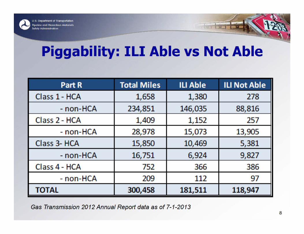
Piggability: Ill Able vs Not Able
Part R Total Miles llLI Able Ill Not Abl 1e 1CI aiss 1 - HCA 1,658 1,380 278
- non-HCA 234,851 146,0135 88 816 , 1C~I a1ss 2 - HCA 1 ~4019 , 1,152 257
~ non~ IHCA 28,978 15,0173, 13 .. 905 1CI ass 3- HCA 15,850 10469 , 5.,381
- n1on-HCA 16,751 6,924 9 827 .. 1C~ a1ss 4 - HCA 752 366 386
- n1on-HCA 209 112 97
TOTAL 300,458 181,511 118,947
Gas Transmission 2012 Annual Report data as of 7-1-2013 8

Summary of Gas Transmission (GT) Pipe
Location Total GT 0/o in HCA GT HCA Non-HCA Miles Miles Miles
Class 1
Class 2
Class 3
Class 4
Total
237, 756
30,210
32,613
962
301,540
0.7
4.7
48.6
78.2
1,660
1,412
15,854
752
19,678
Data as of 7-1-2013 from Part Q of Operator Annual Reports
236,096
28,798
16,759
209
281,862
9

Aging Infrastructure: 0/o by Decade in USA
lll n k.nov.i:n & 2% <1920
19205 2% 2%,
19305 30· 4% 6% 3% 1o ~ ~ 0 Q
19405 9% CD 7% CD 2% 2% U) I() c ~ ~ Q
19505 20o/o 22% 10% ,..._
8% 0 ~ "'Q'
19605 21% 23% 11,a 13%
1970s 16% 11% 12% 14%
191805 91% '#. 10% 'ct. 14% 17%
191905 11% "'Q'
11o/o N 21% 22% "'Q' "'Q'
2.0005 9,3 10% 18% 2.1% 10

Nominal Pipe Size
• Intrastate • Interstate
•
11

Pressure Test Range
Pressure Test Range Total MUes Ofo Total
IPT < 1.1 IMAOP or no PT 93,817 31°/o ,_
1.25 MAOP > PT> 1 .. 1 MAOP 19,131 6 '0/o
IPT > l ,"25 MAOP 187,628 62°/o
Gas Transmission 2012 Operator Annual Report data as-of 7-1-2013
12

Seam Study Comprehensive Study to Understand
Longitudinal ERW Seam Failures
• Research Contractor: Phase 1 - Battelle
• Subcontractors: Phase 1 - Det Norske Veritas (DNV) & Kiefner and Associates
(KAI)
• Principle Investigators: Phase 1 - Bruce Young - Battelle
- Brian Leis & Bruce Nestleroth, in conjunction with
- John Kiefner (KAI) & John Beavers (DNV)
• Phase 1 Completed - Jan. 2014; Phase 2 underway 13

Phase 1- Findings
• ILi Detection & Sizing: - Ill results show inconsistencies with digs & hydro test
results • May be due to either ILI tool findings or interpretation
- Ill tools are useful for finding & eliminating some seam defects
• In-the-Ditch Assessment Methods o No consistent standard practice o Can be inspector dependent
• In-the-Ditch / ILi Improvements required for: - More specific identification of anomaly type - Reduction of false calls - Improved sizing of defect depth and length for effective
assessment and evaluation results 14

Phase 1- Findings
• Failure Pressure Models - Should use a more representative Charpy impact
toughness position relative to the bond line - Toughness values when unknown, need to be
conservative • Predictive Model for Assessing Failure Stress Levels
- Must be based upon whether the failure is brittle or ductile, if unknown evaluate for both
- Must use lower-bound failure stress levels based upon defect type (cold weld, hook cracks, stress corrosion cracking, etc.)
15

Phase 1- Findings
• Hydrostatic test pressures
- Need to be higher to be effective based upon a review of over 600 seam failures
- Time to failure increases at an exponential rate to increased test pressure
- Higher test pressures should mean longer interval before a retest
16

Phase 2 - Overview
1. Improve hydrotesting protocols for ERW/FW Seams
2. Enhance Defect Detection and Sizing via Inspection
3. Defect Characterization: Types, Sizes, & Shapes
4. Develop & Refine Predictive Models & Quantify Growth Mechanisms
5. Develop Management Tools
6. Public Meeting/Forum Completed reports for Phase 1 available at:
https: I/prim is. phmsa. dot. gov /matrix/PrjHome. rd m ?prj =39{}

Integrity Verification Process (IVP)
Overview of Basic Pri nci pies
18

Principle #1 Apply to Higher Risk Locations
• High Consequence Areas (HCAs) • Moderate Consequence Area (MCA):
Onshore area within a potential impact circle Containing one or more buildings intended for human occupancy
c Occupied site or designated Federal interstate, expressway, or 4-lane highway right-of-way
o Does not meet definition of high consequence area, as defined in § 192.903.
• PHMSA Estimates - -- 76,000 miles HCA/MCA (out of -- 301,000 miles)
19

Principle #2 Screen for Categories of Concern
• Apply process to pipeline segments with:
Grandfathered Pipe
Lack of Records to Substantiate MAOP
o Lack of Adequate Pressure Test
c Operating pressures over 72°/o SMYS (pre-Code)
o History of Failures Attributable to Manufacturing & Construction Defects
20

Principle #3 Know & Document Pipe Material Inadequate Validated, Non-traceable Material Documentation, Establish Material Properties by an approved process:
Cut out and Test Pipe Samples (Code approved process) o In Situ Non-Destructive Testing (if validated and if Code
approved) o Field verification of code stamp for components
such as valves, flanges, and fabrications o Other verifications
21

Principle #4 Assessments to Establish MAOP
• Allow Operator to Select Best Option to Establish MAOP
• Candidate IVP Options for Establishing MAOP
o Subpart J Pressure Test with Spike Test
o Derate Operating Pressure
o Engineering Critical Assessment
o Replace Pipe Segment
o Alternative Technology or Technical Options
o Other options PHMSA should consider? 22

n erification Process (IVP) Chart
• Applicable Segments - (Steps 1, 2, 3 and 4)
• MAOP Determination Methods (Steps 5 - 10) - Pressure Test
Pressure Reduction Engineering Critical Assessment (ECA) Pipe Replacement
- Pressure Reduction for Segments w/Small PIR
- Alternative Technology • Materials Documentation
(11) - Destructive - Non-destructive
• Continue Operations (12)
-ii!rt[fty t'dbftln 11!-oc: .. [HPJ S• rtr.•1
L CTllwml:lol"'**"
~~ i l:lomty i«bli ....... l!l"ft-m-1111 tlll ftll'"' f>'FU
l. :V:,'>~m
ia ..... ciitdl
PHMSA DRAFT IVP CHART 9/10/2013 Gas Transmission 49 CJR Part 192 •11,1nwnl.1111t:l c :
!!CA• Kl.Cilmf,O' KA- J,O'
Kl.Clo• h 1'M\Cf 1lt!Ullll!,., WCAO... l nP~'!llll!U
FMrtm*• tal tlcazntm&AFUIC!U r~-v
---.11~:1--·~- ~dldC.JPto:ml
.Wo.c-t-hr 1.W:P--6 u
Oobllcfll>llrtil --!bfll Sot lhl l
°"""' *"<It ""*kllD
... ftP'!(J•tD
"'c""'.....-." -.. -propo!!l!L " """ blltdlll ... Pm --plq pfQf'ft . ,, um. .. llvN:f ,moli1...S -.. -dladw.a.Clt
""'"'"""'.U• -;..i· NIP~"!
-L<Ual c.;,.._,.1.M uuipcbator .......... ~ ..... . .. ,,S-.. Clftlfh.i ltde<tl. •
http:llprimis.phmsa.dot.govlmeetings!MtgHome.mtg?mtg=91 23

Why are pipeline material records needed?
To establish design and MAOP • For integrity management (IM)
• Anomaly evaluations for safe operating pressure
• Record Types: o Materials o Design o Construction o Pressure Testing o Corrosion Control o O&M-
o IM, Surveys, Patrols, Manuals, Procedures
-..ww~HE ... ~ ,,_,.,.,T. W».PlleM
"""""""
110 lH nz na 1GO il)O 100 100
8t , 1 85 eo too too 100 100
24

Material Documentation Plan • Procedures
- Tests for: • Yield strength, ultimate tensile strength, seam type,
coating type and chemistry - Destructive Tests
• Pipe removed from replacements and relocations - Destructive and/or Non-Destructive Tests
• Direct examinations, repairs, remediation & maintenance
- Tests used only to verify and document material grade
25

MAOP Determination
• Applicable Locations
- Located in HCA, MCA, and meets any of the following:
• Experienced reportable in-service incident since last pressure test due ...
• Legacy pipe or constructed with legacy construction techniques and has not had a Pressure Test (PT) of the greater of
- 1.25 times MAOP or applicable Class location PT requirement
• No PT records
• MAOP established per Grandfather Clause
26

MAOP Determination
• Pressure Test
- 1.25 or class location test factor times MAOP
- Spike test segments w/ reportable in-service incident due to legacy pipe/construction and cracking
- Estimate remaining life, segments w/crack defects
• Pressure Reduction
- Reduce pressure by MAOP divided by class location test factor
- Estimate remaining life, segments w/crack defects • Pipe Replacement
- Install new pipe that meets Code requirements
27

MAOP Determination
• Engineering Critical Assessment (ECA) - ECA analysis - for MAOP
• Segment specific technical and material documentation issues
• Analyze crack, metal loss, and interacting defects remaining in pipe, or could remain in the pipe, to determine MAOP
• MAOP established
• Alternative Technology - Alternative technical evaluation process that provides a
sound engineering basis for establishing MAOP
28

Regulatory Action - Status Update
• Notice of Proposed Rulemaking (NPRM)
- Regulation drafted
- Being routed for approval to notice to Public
• Applicable to Gas Transmission Pipelines
- 49 Code of Federal Regulations Part 192
29

Regulatory Next Steps in Addressing Pipeline Seam Weld Challenges
Stay Tuned
Know what's below. Call before you dig.


![Proceedings of - Applus+86e60015...could impact weld integrity. -ERW seams are aLF common long seam type for line pipe manufactured from the 1930s through 1970[2]. This welding process](https://img.dokumen.tips/doc/110x75/5e992ec50093ff5d8a1a56d8/proceedings-of-applus-86e60015-could-impact-weld-integrity-erw-seams-are.jpg)


![Seam - ####### [###20080327] - JBoss...Table of Contents JBoss Seam## .....xi 1. Seam ## .....1](https://img.dokumen.tips/doc/110x75/60d604b5fa8e121d9f6a07dc/seam-20080327-jboss-table-of-contents-jboss-seam-xi.jpg)